Please refer to RP-213598 for detailed scope of the WI.
R1-2203886������� Work plan for Rel-18 Evolved MIMO������ Samsung
Including extension for indication of multiple DL/UL TCI states, simultaneous multi-panel UL transmission, and power control for UL single DCI.
R1-2204367������� Discussion on unified TCI framework extension for multi-TRP������� NTT DOCOMO, INC.
� Proposal 2-1: Specify joint TCI state and separate UL/DL TCI state to support all of following Rel.16/17 M-TRP schemes:
o Single/multi-DCI based M-TRP PDSCH NCJT in Rel.16
o Single-DCI based M-TRP PDSCH repetition with SDM/FDM/TDM in Rel.16
o M-TRP PDCCH/PUSCH/PUCCH repetition in Rel.17
o M-TRP inter cell in Rel.17
o SFN-PDCCH/PDSCH in Rel.17
o M-TRP BFR in Rel.17
� Proposal 2-2:
o The number of �indicated TCI states� can be up to 2 to support Rel.16/17 M-TRP features.
� If more than 2 TCI states are required in Rel.18, the number of �indicated TCI states� is also increased to support Rel.18 schemes.
o Specify different signaling mechanism to support unified TCI framework for M-TRP for the following schemes:
� Single-DCI based M-TRP (for ideal backhaul scenario):
� One beam indication DCI can indicate up to two �indicated TCI states�.
� Multi-DCI based M-TRP (for ideal/non-ideal backhaul scenario):
� One beam indication DCI can indicate one �indicated TCI states� for a TRP.
� Proposal 2-3: Strive to use one TCI state field (i.e. not adding second TCI state field).
o Discuss whether to increase the max. number of bits for TCI state field in DCI format 1_1/1_2.
o Consider RRC configurable size of TCI state field in DCI format 1_1.
� Proposal 2-4: For unified TCI extension for single-DCI based multi-TRP,
o For joint TCI state, one TCI codepoint corresponds to up to two joint TCI states.
o For separate DL/UL TCI state, one TCI codepoint corresponds to up to two DL TCI states and/or up to two UL TCI states.
� Proposal 2-5: For unified TCI extension for multi-DCI based multi-TRP, definition of CORESETPoolIndex = {0, 1} is reused.
� Proposal 2-6: For unified TCI extension for multi-DCI based multi-TRP,
o For joint TCI state, one DCI associated with CORESETPoolIndex = 0 indicates one joint TCI state (1st indicated TCI state), and the other DCI associated with CORESETPoolIndex = 1 indicates one joint TCI state (2nd indicated TCI state).
o For separate TCI state, one DCI associated with CORESETPoolIndex = 0 indicates one DL TCI state and/or one UL TCI state (1st indicated TCI state), and the other DCI associated with CORESETPoolIndex = 1 indicates one DL TCI state and/or one UL TCI state (2nd indicated TCI state).
� Proposal 2-7: For unified TCI extension for multi-DCI based multi-TRP, discuss whether to increase the max. number of RRC configured TCI states from Rel.17.
� Proposal 3-1: The extension of unified TCI framework can be applied to simultaneous multi-panel PUSCH/PUCCH Tx schemes (if supported). Details can be discussed after the support of simultaneous multi-panel PUSCH/PUCCH transmission schemes is discussed and decided in agenda item 9.1.4.1.
� Proposal 4-1: For M-TRP operation, with extension of unified TCI framework, per TRP power control can be supported by Rel-17 unified TCI power control framework, i.e., power control parameters are associated with each TCI state.
� Proposal 4-2: For simultaneous multi-panel PUSCH/PUCCH Tx scheme (if supported), how to determine PCMAX for transmission from each panel can be further studied.
Decision: The document is noted.
R1-2204684�������� Unified TCI framework extension for multi-TRP������� MediaTek Inc.
R1-2203061�������� Unified TCI framework extension for multi-TRP������� FUTUREWEI
R1-2203149�������� Discussion on unified TCI framework extension for multi-TRP������������� Huawei, HiSilicon
R1-2203174�������� Discussion on Unified TCI framework extension for multi-TRP������������ CEWiT
R1-2203263�������� Enhancements on unified TCI framework extension for multi-TRP������� ZTE
R1-2203320�������� Discussion on unified TCI framework extension for multi-TRP������������� Spreadtrum Communications
R1-2203378�������� On Extension of Unified TCI Framework���� InterDigital, Inc.
R1-2203441�������� On unified TCI framework extension for multi-TRP operation CATT
R1-2203541�������� Views on unified TCI framework extension for multi-TRP������ vivo
R1-2203681�������� Discussion on unified TCI framework extension for multi-TRP������������� NEC
R1-2203723�������� Consideration on Unified TCI framework for multi-TRP��������� Sony
R1-2203793�������� Unified TCI framework extension for multi-TRP������� xiaomi
R1-2203887�������� Views on unified TCI extension focusing on m-TRP� Samsung
R1-2203953�������� Unified TCI framework extension for multi-TRP������� OPPO
R1-2204033�������� Unified TCI framework extension for multi-TRP������� Ericsson
R1-2204141�������� Unified TCI framework extension for multi-TRP/panel����������� LG Electronics
R1-2204162�������� Discussion of unified TCI framework for multi-TRP� Lenovo
R1-2204229�������� Views on unified TCI framework extension for multi-TRP������ Apple
R1-2204287�������� Discussion on unified TCI framework extension for multi-TRP������������� CMCC
R1-2204440�������� Discussion on unified TCI framework extension for multi-TRP������������� ITRI
R1-2204506�������� Unified TCI framework extension for multi-TRP������� Sharp
R1-2204538�������� Unified TCI framework extension for multi-TRP������� Nokia, Nokia Shanghai Bell
R1-2204584�������� Enhancement on unified TCI framework for multi-TRP����������� Transsion Holdings
R1-2204678�������� Multi-TRP enhancements for the unified TCI framework�������� Fraunhofer IIS, Fraunhofer HHI
R1-2204785�������� On Unified TCI framework for mTRP���������� Intel Corporation
R1-2204857�������� Unified TCI framework extension for multi-TRP������� AT&T
R1-2205014�������� Extension of unified TCI framework for mTRP���������� Qualcomm Incorporated
R1-2205071�������� Discussion on unified TCI framework extension for multi-TRP������������� FGI
R1-2205074�������� Considerations on unified TCI for mTRP����� Fujitsu Limited
[109-e-R18-MIMO-01] � Darcy (MediaTek)
Email discussion on unified TCI framework extension for multi-TRP by May 20
- Check points: May 12, May 18, May 20
R1-2205225������� Moderator summary on extension of unified TCI framework for MTRP (Round 1)���������� Moderator (MediaTek Inc.)
From May 12th GTW session
Proposal 1.B-2:
On unified TCI framework extension, support up to 4 indicated TCI states in a CC/BWP for MTRP operation
� The indicated TCI states are updated by MAC-CE or DCI with the necessary MAC-CE based TCI state activation
� The UE can be provided with one of the following combinations of indicated TCI states for DL and/or UL MTRP operations in a CC/BWP:
- 1 indicated joint TCI state + 1 indicated joint TCI state
- 1 pair of indicated DL and UL TCI states + 1 pair of indicated DL and UL TCI states
- 1 pair of indicated DL and UL TCI states + 1 indicated DL TCI state
- 1 pair of indicated DL and UL TCI states + 1 indicated UL TCI state
- FFS: 1 indicated joint TCI state + 1 pair of indicated DL and UL TCI states
- FFS: 1 indicated joint TCI state + 1 indicated DL TCI state
- FFS: 1 indicated joint TCI state + 1 indicated UL TCI state
� FFS: How to provide one of above combinations for a CC/BWP
� FFS: Details of update and activation for the indicated TCI states for S-DCI based MTRP
� FFS: Details of update and activation for the indicated TCI states for M-DCI based MTRP
� FFS: How to map/apply one or more indicated TCI states to a target channel(s)/signal(s)
Decision: As per email decision posted on May 14th,
Agreement
On unified TCI framework extension, consider all the intra and inter-cell MTRP schemes specified in Rel-16 and Rel-17
� Consider, if STxMP is supported, Rel-18 MTRP scheme(s) with STxMP
Agreement
On unified TCI framework extension, if an indicated joint or UL TCI state applies to a PUSCH /PUCCH transmission occasion at least for S-DCI based PUSCH/PUCCH repetition with TDM and the indicated joint or UL TCI state is associated with an UL PC parameter setting for PUSCH /PUCCH (including P0, alpha for PUSCH , and closed loop index) and a PL-RS, the UE should apply the UL PC parameter setting and the PL-RS for the PUSCH /PUCCH transmission occasion.
� FFS: How to extend to other Rel-18 MTRP scheme(s) with STxMP, if supported
� FFS: UL PC enhancement for CB and non-CB SRS in above case
FFS: The applied UL PC parameter setting if one or both indicated joint or UL TCI state(s) is not associated with an UL PC parameter setting (including P0, alpha for PUSCH, and closed loop index) for PUCCH/PUSCH
Decision: As per email decision posted on May 20th,
Agreement
On unified TCI framework extension at least for single-DCI based MTRP, the existing TCI field in DCI format 1_1/1_2 (with or without DL assignment) can indicate multiple joint/DL/UL TCI states in a CC/BWP or a set of CCs/BWPs in a CC list
Note: The term TRP is used only for the purposes of discussions in RAN1 and whether/how to capture this is FFS
Agreement
On UE power limitation for STxMP for FR2, send LS to RAN4 to check the followings:
FFS: Detail of exact LS if agreed
Note: Scenarios of above include at least single carrier scenario for FR2
Note: Above power limitation includes both total radiated power and EIRP
LS to RAN4 (approved on May 24th, see below).
R1-2205314������� Moderator summary on extension of unified TCI framework for MTRP (Round 2)���������� Moderator (MediaTek Inc.)
From May 20th GTW session
Agreement
On unified TCI framework extension for M-DCI based MTRP, consider the following alternatives for TCI state update:
� Alt1: Reuse the same TCI state update scheme for S-DCI based MTRP
� Atl2: Use the existing TCI field in the DCI format 1_1/1_2 (with or without DL assignment) associated with one of CORESETPoolIndex values to indicate the joint/DL/UL TCI state(s) corresponding to the same CORESETPoolIndex value
� Alt3: Use the existing TCI field in any DCI format 1_1/1_2 (with or without DL assignment) to indicate all joint/DL/UL TCI states corresponding to both CORESETPoolIndex values
o Study the association between the indicated joint/DL/UL TCI state(s) and a CORESETPoolIndex value
� Alt4: Use the existing TCI field in the DCI format 1_1/1_2 (with or without DL assignment) associated with one of CORESETPoolIndex values to indicate joint/DL/UL TCI state(s) corresponding to the same or different CORESETPoolIndex value.
o Study whether the indicated joint/DL/UL TCI state(s) applies to the channels/signals associated with the same CORESETPoolIndex value or different CORESETPoolIndex value is indicated by DCI
Agreement
On unified TCI framework extension for S-DCI based MTRP, consider at least the following alternatives to map/associate a joint/DL TCI state to PDCCH reception(s)
� Atl1: Use RRC configuration to inform the mapping/association between a configured or indicated joint/DL TCI state and a CORESET or a CORESET group
� Alt2: Use RRC configuration to inform the mapping/association between a configured or indicated joint/DL TCI state and a search space set
� Alt3: Use MAC-CE to inform the mapping/association between an activated or indicated joint/DL TCI state and a CORESET or a CORESET group
� Alt4: Use DCI to inform the mapping/association between an indicated joint/DL TCI state and a CORESET or a CORESET group
� Alt5: Based on a fixed mapping/association rule, e.g., the first indicated joint/DL TCI state always applies to PDCCH receptions
Consider above alternatives for PDCCH repetition, PDCCH-SFN, PDCCH w/o repetition/SFN, and potential support of dynamic switching between S-TRP and M-TRP for PDCCH. It is not precluded to adopt one single alternative or multiple alternatives to support these cases.
R1-2205639������� LS on UE power limitation for STxMP in FR2������� RAN1, MediaTek
Decision: As per email decision posted on May 24th, the LS is approved.
R1-2203062������� Enhancements to support two TAs for multi-DCI� FUTUREWEI
� Proposal 1: For UL multi-DCI for multi-TRP operation, support two TA offsets (e.g., TRP/panel-specific), and two UL TA reference timings (e.g., TRP-specific).
� Proposal 2: For UL multi-DCI for multi-TRP operation, support to acquire and maintain Two TA values for multiple TRPs on the same carrier via PRACH enhancement and TA configuration enhancement.
Decision: The document is noted.
R1-2203150�������� Discussion on TA enhancement for UL M-TRP transmission�� Huawei, HiSilicon
R1-2203264�������� TA enhancement for multi-DCI������ ZTE
R1-2203321�������� Discussion on two TAs for multi-DCI based multi-TRP����������� Spreadtrum Communications
R1-2203379�������� Discussion on Multiple TA for multi-TRP��� InterDigital, Inc.
R1-2203442�������� On Two TAs for UL multi-DCI for multi-TRP operation��������� CATT
R1-2203542�������� Views on two TAs for multi-DCI-based multi-TRP operation� vivo
R1-2203682�������� Discussion on two TAs for multi-DCI���������� NEC
R1-2203724�������� Considerations on two TAs for multi-DCI��� Sony
R1-2203794�������� Discussion on two TAs for multi-TRP operation�������� xiaomi
R1-2203888�������� Views on two TAs for m-DCI��������� Samsung
R1-2203954�������� Two TAs for multi-DCI��� OPPO
R1-2204034�������� Two TAs for multi-DCI��� Ericsson
R1-2204142�������� Two TAs for multi-TRP/panel�������� LG Electronics
R1-2204163�������� Discussion of two TAs for multi-DCI UL transmission������������ Lenovo
R1-2204230�������� On two Timing Advances for multi-DCI Uplink transmissions Apple
R1-2204288�������� Discussion on two TAs for multi-DCI���������� CMCC
R1-2204368�������� Discussion on two TAs for multi-DCI���������� NTT DOCOMO, INC.
R1-2204507�������� Two TAs for multi-DCI��� Sharp
R1-2204539�������� Two TAs for UL multi-DCI multi-TRP operation������ Nokia, Nokia Shanghai Bell
R1-2204786�������� On two TAs for multi-DCI Intel Corporation
R1-2205015�������� Supporting two TAs for multi-DCI based mTRP�������� Qualcomm Incorporated
[109-e-R18-MIMO-02] � Siva (Ericsson)
Email discussion on two TAs for multi-DCI by May 20
- Check points: May 12, May 18, May 20
R1-2205209������� Moderator Summary #1 on Two TA enhancements for multi-DCI based multi-TRP operation�� Moderator (Ericsson)
From May 12th GTW session
Agreement
Enhancement on two TAs for UL multi-DCI for multi-TRP operation is supported in Rel-18.
� Note 1: whether (1) the network signals two TACs or (2) the network signals one TAC and the UE deriving the second TA can be further studied.
� Note 2: evaluations can be considered on as-needed basis.
Agreement
For multi-DCI based multi-TRP operation, down-select one of the two alternatives:
� Alt 1: configure two TAGs within a serving cell
� Alt 2: consider two TAs within one TAG within a serving cell
Agreement
Support two TA enhancement for both intra-cell and inter-cell multi-DCI multi-TRP scenarios in Rel-18.
Decision: As per email decision posted on May 15th,
Agreement
Enhancements on two TAs for UL multi-DCI for multi-TRP operation are applicable to both FR1 and FR2.
Agreement
For multi-DCI multi-TRP operation with two TAs, study the following alternatives:
� Alt 1: two reference timings are considered
� Alt 2: one reference timing is considered
Note: reference timing above is the timing of the DL reception
Decision: As per email decision posted on May 19th,
Agreement
For multi-DCI multi-TRP operation with two TAs, study the following alternatives further in Rel-18:
� Alt 1: one n-TimingAdvanceOffset value per serving cell
� Alt 2: two n-TimingAdvanceOffset value per serving cell
Decision: As per email decision posted on May 20th,
Conclusion
For multi-DCI multi-TRP operation with two TAs, the decision on the maximum uplink timing difference is left up to RAN4.
� Send an LS to RAN4 asking them the maximum uplink timing difference RAN1 can assume between the two TAs for multi-DCI multi-TRP operation.
Agreement
Two TA enhancement for uplink multi-DCI based multi-TRP operation are applicable to at least:
� TDM based multi-DCI uplink transmission
� Simultaneous multi-DCI uplink transmission (if simultaneous uplink multi-DCI uplink transmission is supported in Agenda 9.1.4.1)
� Note: Whether two TA enhancement is applicable to other schemes is a separate discussion, which is not in the scope of AI 9.1.1.2.
R1-2205592������� [Draft] LS on maximum uplink timing difference for Multi-DCI Multi-TRP with two TAs����� Ericsson
Decision: As per email decision posted on May 20th, the draft LS is endorsed. Approved in R1-2205593.
Including CSI enhancement for high/medium UE velocities and coherent JT (CJT).
R1-2204540������� CSI enhancement for high/medium UE velocities and CJT Nokia, Nokia Shanghai Bell
Hereafter is a summary of proposals for CSI enhancement in high/medium velocities.
Proposal 1������������� Study the following CSI reporting enhancement schemes for medium/high speed UEs, based on:
� Reporting of Doppler spread measured by a UE via TRS. The gNB uses the reported Doppler spread to adapt the CSI reporting period and CSI-RS period to a UE�s velocity.
� Channel prediction at the UE. A UE predicts the channel at one or more future time slots from past CSI-RS measurements and reports one or more predicted PMIs in the same report. The study should include
o Whether CSI-RS only or a combination of CSI-RS and TRS can be used for prediction
o
Assumption
that PMIs in a report share the
same ![]() �and
�and ![]() �
�
o CQI reporting based on multiple reported PMIs
� Precoder prediction at the gNB. A UE reports multiple PMIs calculated from past CSI-RS measurements in one report. The study should include
o CSI-RS configuration in time
o
Assumption
that PMIs in a report share the same ![]() �and
�and ![]() .� Compression of
.� Compression of ![]() �in time by using orthogonal basis vectors
�in time by using orthogonal basis vectors
o CQI reporting based on multiple reported PMIs
Proposal 2������������ For the study of CSI reporting enhancement
schemes for medium/high speed UEs based on channel prediction at the UE,
consider a case where a UE is configured to report 2 Rel-16 Type-II PMIs in the
same CSI report corresponding to future time slots ![]() �and
�and ![]() , where
, where ![]() �is the slot in which the CSI report is
received, and
�is the slot in which the CSI report is
received, and ![]() �where
�where ![]() �is the CSI reporting period.
�is the CSI reporting period.
Proposal 3������������ For the study of CSI reporting enhancement schemes for medium/high speed UEs based on channel prediction at the UE, consider two alternatives for channel measurement:
� Single CSI-RS occasion and TRS
� Multiple CSI-RS occasions
Proposal 4������������ For the study of CSI reporting enhancement
schemes for medium/high speed UEs based on channel prediction at the UE,
consider a codebook refinement whereby two PMIs are reported in the same CSI
report corresponding to precoders:
![]() , for
, for ![]()
Proposal 5������������ For the study of CSI reporting enhancement
schemes for medium/high speed UEs based on channel prediction at the UE,
consider reporting a single CQI associated to the two PMIs at slot ![]() �and
�and ![]() , calculated by assuming that the PDSCH
transmission lasts
, calculated by assuming that the PDSCH
transmission lasts ![]() �slots and that the PDSCH signal is precoded
by
�slots and that the PDSCH signal is precoded
by ![]() �for the first
�for the first ![]() �slots and by
�slots and by ![]() �for the second
�for the second ![]() �slots.
�slots.
Proposal 6������������ For the study of CSI reporting enhancement
schemes for medium/high speed UEs based on precoder prediction at the gNB,
consider a ![]() �compression scheme whereby
�compression scheme whereby ![]() �PMIs are reported in the same CSI report
corresponding to precoders
�PMIs are reported in the same CSI report
corresponding to precoders
![]() , for
, for ![]()
where
![]() �are the time slots of the latest
�are the time slots of the latest ![]() �CSI-RS measurement occasions, and where
�CSI-RS measurement occasions, and where ![]() �are the elements of an
�are the elements of an ![]() �compression matrix
�compression matrix ![]() , with
, with ![]() .
.
Proposal 7������������ For the study of UE�s reporting of time/Doppler information based on TRS measurements, consider the following use cases:
1. in FDD, UE�s reporting of Doppler spread allows a gNB to adapt the periodicity of CSI reporting or CSI prediction times and the periodicity of CSI-RS to the channel coherence time
2. in TDD, when full UL/DL channel reciprocity can be assumed, the gNB may use time-correlation or Doppler spectrum reported by a UE to predict the evolution in time of the channel measured from SRS and calculate precoding weights for the PDSCH/DMRS based on the predicted channel.
Proposal 8������������ For system level performance evaluation of CSI enhancement schemes for medium/high speed UEs, adopt the SLS assumptions from Rel-16 eType-II with the following modifications
|
Frequency Range |
FR1 only, 2 GHz. |
|
|
Scenario |
Dense Urban (macro only) |
Rural Macro (RMa) |
|
Inter-site distance |
200 m |
1.7 Km |
|
UE distribution |
100% outdoor (30Km/h) |
� 100% outdoor (100Km/h) |
|
Mobility model |
Spatial consistency model - Procedure A from 38.901, Sec. 7.6.3.2 |
|
|
Evaluation Metric |
Throughput adjusted by CSI-RS overhead versus CSI feedback overhead |
|
|
Baseline for performance evaluation |
Rel-16 Type II Codebook with 5ms CSI feedback periodicity and 4ms scheduling delay |
|
Hereafter is a summary of proposals for CJT Type-II enhancement in FDD.
Proposal 9������������ For the study of Type-II support for CJT in FDD FR1, prioritise enhancement for Rel-16 Type-II regular CB and consider the following aspects
� Modifications needed to the CSI Reporting Setting
�
Joint
or separate determination of codebook components ![]() �for different TRPs
�for different TRPs
Proposal 10���������� For CJT Type-II reporting in FDD FR1,
support the definition of ![]() �Port Groups in a CSI Resource Setting
configuration, with
�Port Groups in a CSI Resource Setting
configuration, with ![]() , according to the following alternatives:
, according to the following alternatives:
1.
In
a Resource Set configured with a single CMR with ![]() �ports, a Port Group contains
�ports, a Port Group contains ![]() �ports
�ports
2.
In
a Resource Set configured with ![]() �CMRs with
�CMRs with ![]() �ports each, a Port Group contains the
�ports each, a Port Group contains the ![]() �ports of a CMR.
�ports of a CMR.
Proposal 11���������� For CJT Type-II reporting in FDD FR1 with ![]() �TRPs, assume that the total number of beams
�TRPs, assume that the total number of beams
![]() �in
�in ![]() �is network configured. Study whether to
support one or both alternatives:
�is network configured. Study whether to
support one or both alternatives:
1.
UE
selects ![]() �beams per TRP
�beams per TRP
2.
UE
selects ![]() �beams for TRP
�beams for TRP ![]() , with
, with ![]() �and
�and ![]()
Proposal 12���������� For CJT Type-II reporting in FDD FR1 with ![]() �TRPs, support UE�s joint selection of
�TRPs, support UE�s joint selection of ![]() �FD basis components of
�FD basis components of ![]() �for all TRPs
�for all TRPs
Proposal 13���������� For CJT Type-II reporting in FDD FR1 with ![]() �TRPs, study ways to optimise the overlap
between the strongest FD basis components of different TRPs, e.g., by
introducing a cyclic shift (i.e., phase ramp) for each TRP with respect
to a reference TRP.
�TRPs, study ways to optimise the overlap
between the strongest FD basis components of different TRPs, e.g., by
introducing a cyclic shift (i.e., phase ramp) for each TRP with respect
to a reference TRP.
Proposal 14���������� For CJT Type-II reporting in FDD FR1 with ![]() �TRPs, study ways to reduce the power
imbalance between
�TRPs, study ways to reduce the power
imbalance between ![]() �coefficients of different TRPs, caused by
different RSRPs, e.g., by reporting an additional reference amplitude,
such as the reference amplitude of the stronger polarisation, for each TRP with
respect to the TRP with the strongest coefficient.
�coefficients of different TRPs, caused by
different RSRPs, e.g., by reporting an additional reference amplitude,
such as the reference amplitude of the stronger polarisation, for each TRP with
respect to the TRP with the strongest coefficient.
Proposal 15���������� For system level performance evaluation of CSI enhancement schemes for CJT in FDD operations, adopt the SLS assumptions from Rel-16 eType-II with the following modifications
|
Parameters |
Scenarios |
|
|
A: Intra-site (Macro + RRH)
|
B: Inter-site (Macro-only)
|
|
|
Inter-site distances |
1.7 km |
200 m |
|
Carrier frequencies |
0.7 GHz |
2 GHz, 4 GHz (optional) |
|
Channel type |
Rural (RMa) |
Urban Macro (Uma) |
|
Simulation bandwidth |
10MHz |
|
|
BS Transmit Power |
Macro: 46 dBm RRH: 46 dBm |
Macro: 46 dBm |
|
BS Height |
Macro: 35 m RRH: 35m |
Macro: 25m |
|
BS Antenna Configuration |
4 ports: (M,N,P,Mg,Ng,N1,N2) = (8,2,2,1,1,1,2) 100�mechanical elevation tilt |
16 ports: (M,N,P,Mg,Ng,N1,N2)� = (8,4,2,1,1,2,4) 100�mechanical elevation tilt |
|
UE Distribution |
100% outdoor |
20% outdoor |
|
UE Antenna Configuration |
2 Rx: (M,N,P) = (1,1,2) 4 Rx: (M,N,P) = (1,2,2) |
|
|
UE speed |
3 kmph |
|
|
Traffic Model |
FTP Model 1: 20/50% target RU |
|
|
Receiver |
Non-ideal 2RX MMSE |
Non-ideal 4RX MMSE |
|
CJT Scheduling Set Size |
Intra-sector: 4 TRPs (1 Macro + 3 RRHs) Intra-site: 12 TRPs (3 Macros + 9 RRHs) |
Intra-site: 3 TRPs Inter-site: 6 or 9 TRPs |
Decision: The document is noted.
R1-2203151�������� CSI enhancement for coherent JT and mobility���������� Huawei, HiSilicon
R1-2203229�������� On CSI enhancements for Rel-18 NR MIMO evolution����������� Ericsson
R1-2203265�������� CSI enhancement for high/medium UE velocities and CJT������ ZTE
R1-2203322�������� Discussion on CSI enhancement for coherent JT�������� Spreadtrum Communications
R1-2203380�������� Aspects of CSI Enhancements�������� InterDigital, Inc.
R1-2203443�������� On Rel-18 CSI enhancements��������� CATT
R1-2203543�������� Views on CSI enhancement for high-medium UE velocities and coherent JT������ vivo
R1-2203683�������� Discussion on CSI enhancement���� NEC
R1-2203725�������� Considerations on CSI enhancement for high/medium UE velocities and coherent JT (CJT)���� Sony
R1-2203795�������� Discussion on CSI enhancement���� xiaomi
R1-2203890�������� Views on CSI enhancements���������� Samsung
R1-2203955�������� CSI enhancement for high/medium UE velocities and coherent JT�������� OPPO
R1-2204099�������� CSI enhancement for high/medium UE velocities and CJT������ FUTUREWEI
R1-2204143�������� Potential CSI enhancement for high/medium UE velocities and coherent JT�������� LG Electronics
R1-2204164�������� Discussion of CSI enhancement for high speed UE and coherent JT������ Lenovo
R1-2204231�������� Views on Rel-18 MIMO CSI enhancement�� Apple
R1-2204289�������� Discussion on CSI enhancement for high/medium UE velocities and� CJT�������������� CMCC
R1-2204369�������� Discussion on CSI enhancement���� NTT DOCOMO, INC.
R1-2204508�������� CSI enhancement Sharp
R1-2204679�������� CSI enhancements for medium UE velocities and coherent JT Fraunhofer IIS, Fraunhofer HHI
R1-2204691�������� CSI enhancement for high/medium UE velocities and coherent JT�������� MediaTek Inc.
R1-2204748�������� Discussion on CSI Enhancements for high/medium UE velocities and coherent JT�������������� CEWiT
R1-2204787�������� On CSI enhancements������ Intel Corporation
R1-2204858�������� CSI enhancement AT&T
R1-2205016�������� CSI enhancements for high-medium UE velocities and Coherent-JT����� Qualcomm Incorporated
[109-e-R18-MIMO-03] � Eko (Samsung)
Email discussion on CSI enhancement by May 20
- Check points: May 12, May 18, May 20
R1-2203889������� Moderator summary on Rel-18 CSI enhancements Moderator (Samsung)
Decision: As per email decision posted on May 12th,
Agreement
On Rel-18 CSI enhancement EVM for SLS, use what is captured in the excel spreadsheet in R1-2205289.
R1-2205289������� EVM for Rel-18 MIMO CSI enhancements������������ Moderator (Samsung)
Agreement
On Rel-18 CSI enhancement EVM for LLS (only for TRS-based TDCP), companies can use the following simulation assumptions:
� For mTRP 120kmph and over, use Rel-17 HST assumptions (cf. section 2.1 in R1-2007201)
� For sTRP up to 120km/h:
|
Parameter |
Value |
|
Carrier frequency and subcarrier spacing |
3.5 GHz with 30 kHz SCS |
|
System bandwidth |
20MHz, 100MHz |
|
TRS bandwidth |
20MHz, 100MHz |
|
Channel model |
Alt. 1: TDL channels with uncorrelated antenna elements with first priority on TDL-A while the use of other TDL channels isn�t precluded
Alt. 2: CDL channels with first priority on CDL-A while the use of other CDL channels isn�t precluded |
|
Delay spread |
10ns, 30ns, 100ns, 300ns, and 1000ns |
|
UE velocity |
3km/h, 10km/h, 20km/h, 30km/h, 60km/h, 120km/h |
|
Antennas at UE |
4RX: (1,2,2,1,1,1,2), (dH,dV) = (0.5, 0.5)λ for rank > 2 2RX: (1,1,2,1,1,1,1), (dH,dV) = (0.5, 0.5)λ for (rank 1,2) For TRS based Doppler accuracy evaluations a single UE antenna may also be used Other configurations are not precluded. |
|
Antennas at gNB |
32 ports: (8,8,2,1,1,2,8), (dH,dV) = (0.5, 0.8)λ 16 ports: (8,4,2,1,1,2,4), (dH,dV) = (0.5, 0.8)λ For TRS based Doppler accuracy evaluations a single gNB port may also be used. Other configurations are not precluded. |
|
Link adaptation |
For TRS based Doppler accuracy: Not applicable For mode selection performance: Adaptation of both MCS and rank. |
|
Evaluation metrics for measurement accuracies |
RMS error, Standard deviation, Bias |
|
Evaluation metric for Doppler based mode selection |
User throughput |
R1-2205288�������� Moderator Summary#2 on Rel-18 CSI enhancements: ROUND 2���������� Moderator (Samsung)
Decision: As per email decision posted on May 12th,
Agreement
The work scope of Type-II codebook refinement for CJT mTRP includes refinement of the following codebooks:
� Rel-16 eType-II regular codebook
� Rel-17 FeType-II port selection (PS) codebook
FFS: Whether to prioritize/down-select from the two
Agreement
The work scope of Type-II codebook refinement for CJT mTRP includes the support of NTRP={1, 2, 3, 4} cooperating TRPs for CJT CSI report
� FFS: Signaling of NTRP, e.g. higher-layer (RRC) vs. dynamic
� FFS: Determination of NTRP, e.g. NW-configured vs UE-selected
� FFS: Whether to prioritize or only support NTRP={1, 2}
Agreement
The work scope of Type-II codebook refinement for CJT mTRP includes the following NZP CSI-RS (CMR) setups in Resource Setting associated with Rel-18 Type-II codebook for CJT
� Opt1: 1 NZP CSI-RS resource, max # ports = 32
o FFS: whether/how to associate TCI states and CSI-RS ports
� Opt2: K>1 NZP CSI-RS resources with the same number of ports (representing K TRPs)
o FFS: The maximum number of ports per resource, and the total number of ports across all resources
FFS: Whether to prioritize/down-select from the two options
Agreement
The work scope of Type-II codebook refinement for CJT mTRP includes down-selecting at least one or merging from the following codebook structures:
� Alt1A. Per-TRP/TRP group (port-group or resource) SD/FD basis selection + relative co-phasing/amplitude (including WB and/or SB). Example formulation (N = number of TRPs or TRP groups):
o
![]() �= co-amplitude and
�= co-amplitude and
o
![]() �= co-phase
�= co-phase
o
Including special case of ![]() �(no co-scaling) or
�(no co-scaling) or ![]()
� Alt1B. Per-TRP/TRP group (port-group or resource) joint SD-FD basis selection + relative co-phasing/amplitude (including WB and/or SB). Example formulation (N = number of TRPs or TRP groups):
o
![]() �= co-amplitude and
�= co-amplitude and
o
![]() �= co-phase
�= co-phase
o
Including special case of ![]() �(no co-scaling) or
�(no co-scaling) or ![]()
� Alt2. Per-TRP/TRP group (port-group or resource) SD basis selection and joint (across N TRPs) FD basis selection. Example formulation (N = number of TRPs or TRP groups):
Agreement
The work scope of Type-II codebook refinement for high/medium velocities includes refinement of the following codebooks, based on a common design framework:
� Rel-16 eType-II regular codebook
� Rel-17 FeType-II port selection (PS) codebook
FFS: Whether to prioritize/down-select from the two
Agreement
The work scope of Type-II codebook refinement for high/medium velocities includes down selection from the following codebook structures (for discussion purposes):
� Alt1. Time-domain basis,
o
Alt1A: Time-domain basis
commonly selected for all SD/FD bases, e.g. ![]() �
�
o Alt1B: Time-domain basis independently selected for different SD/FD bases
� Alt2. Doppler-domain basis
o
Alt2A: Doppler-domain basis
commonly selected for all SD/FD bases, e.g. ![]()
o Alt2B: Doppler-domain basis independently selected for different SD/FD bases
o
Note that ![]() �may be the identity as a special case
�may be the identity as a special case
�
Alt3. Reuse Rel-16/17 (F)eType-II codebook with
multiple ![]() �and a single
�and a single ![]() �and
�and ![]() �report.
�report.
Agreement
The work scope of Type-II codebook refinement for high/medium velocities includes down selection from the following Doppler-/time-domain basis waveforms for codebook design:
� Alt1. Orthogonal DFT (with or without rotation factor)
� Alt2. Oversampled DFT
� Alt3. Other waveforms, e.g. DCT, Slepian
� Alt4. Identity (i.e. no Doppler-/time-domain compression)
Agreement
The work scope of Type-II codebook refinement for high/medium velocities includes the following CSI measurement and calculation aspects:
� Potential refinement on Resource setting configuration on CSI-RS (for CSI and/or tracking) for measuring a burst of CSI-RS, including the applicable time-domain behaviors
� Whether/how UE-side or gNB-side prediction is assumed for CQI/PMI/RI calculation
� Potential enhancements on CQI definition and calculation procedure in relation to the PMI of Rel-18 Type-II codebook for high/medium velocities
� Potential enhancement on definition of CSI reference resource
Agreement
The work scope of TRS-based TDCP reporting focuses on the following use cases for evaluation purposes:
� Targeting medium and high UE speed, e.g. 10-120km/h as well as HST speed
� Aiding gNB to determine
o CSI reporting configuration and CSI-RS resource configuration parameters,
o Precoding scheme, using one of the CSI feedback based precoding schemes or an UL-SRS reciprocity based precoding scheme
� Aiding gNB-side CSI prediction
Agreement
The work scope of TRS-based TDCP reporting includes down selection from the following TDCP reporting formats:
� Alt1. Stand-alone reporting (no inter-dependence with other CSI/UCI parameters)
o Note: This doesn�t preclude multiplexing with other UCI parameters (e.g. CSI, ACK, SR, �) on PUCCH/PUSCH, if applicable
� Alt2. Inter-dependent and reported with other CSI parameter(s)
Agreement
The work scope of TRS-based TDCP reporting includes down selection from the following TDCP parameters:
� Alt1. Doppler shift
� Alt2. Doppler spread
� Alt3. Cross-correlation in time
� Alt4A. Relative Doppler shift of a number of peaks in CIR
� Alt4B. Relative Doppler shifts of different TRSs
� Alt5: CSI-RS resource and/or CSI reporting setting configuration assistance
R1-2205362������� Moderator Summary#3 on Rel-18 CSI enhancements: ROUND 3��� Moderator (Samsung)
From May 16th GTW session
Agreement
For Rel-18 CSI enhancements, proceed to support and specify the following features (the previously agreed work scopes apply):
� Type-II codebook refinement for CJT mTRP
� Type-II codebook refinement for high/medium UE velocities exploiting time-domain correlation/Doppler-domain information
� UE reporting of time-domain channel properties (TDCP) measured via CSI-RS for tracking
o The use case of aiding gNB-side CSI prediction is to be confirmed in RAN1#110
R1-2205423������� Moderator Summary#4 on Rel-18 CSI enhancements: ROUND 4��� Moderator (Samsung)
Decision: As per email thread posted on May 18th,
Agreement
On the Type-II codebook refinement for CJT mTRP, the resulting codebook(s) are associated with at least the following parameters:
Agreement
For the Type-II codebook refinement for CJT mTRP, further study the following issues:
� The need for the following additional parameters:
o Receiver side information by per RX reporting or per layer, e.g. information related to the left singular matrix U of the channel
o Indication of relative offset of reference FD basis per TRP with respect to a reference TRP
o Information related to the windows for FD basis
o Delay/frequency difference(s) across TRPs
� Specification entity corresponding to a TRP (e.g. port-group, NZP CSI-RS resource)
� For codebooks with per-TRP/TRP-group SD/FD basis (structure Alt1A/1B), whether to support co-amplitude/phase as a part of CSI report (explicit) or not (implicit)
� Design details of reference amplitudes and differential amplitudes in W2:
� Whether/how supported parameter combinations are refined from Rel-16/17
Agreement
On the Type-II codebook refinement for CJT mTRP, down-select from the following TRP selection/determination schemes (where N is the number of cooperating TRPs assumed in PMI reporting):
Agreement
On the Type-II codebook refinement for high/medium velocities, for codebook structures with TD or DD basis (Alt1 or Alt2 from codebook structure agreement), the codebook(s) include at least the following additional codebook parameters:
� Doppler-/time-domain (DD/TD) basis vector length
� Parameters for DD/TD basis vector selection, including
o The number of DD/TD basis vectors
o If applicable, Basis selection indicator(s)
� FFS: restrictions on the basis vector selection
o If applicable, the total number of available DD/TD basis vectors (not needed for orthogonal DFT basis set), whether explicitly or implied from another parameter (e.g. oversampling factor)
Agreement
For the Type-II codebook refinement for high/medium velocities, further study the following issues:
� The need for DD/TD (compression) unit (analogous to PMI sub-band for Rel-16 codebook)
Agreement
On potential refinement of Resource setting configuration associated with Type-II codebook refinement for high/medium velocities, study the following options to assess whether/how the legacy Resource setting configuration needs to be enhanced for �burst� measurement:
� Periodic (P) CSI-RS: periodicity and offset
� Semi-persistent (SP) CSI-RS: activation/deactivation, periodicity, and offset
� Aperiodic (AP) CSI-RS: triggering, offset of a group of AP CSI-RS resources
FFS: Support for K>1 NZP CSI-RS resources association with Type-II codebook refinement for high/medium velocities
FFS: Whether specification support for jointly utilizing two types of CSI-RS time-domain behaviors is needed
Agreement
The TRS-based TDCP reporting is down selected from the following alternatives:
R1-2205470������� Moderator Summary#5 on Rel-18 CSI enhancements: ROUND 5��� Moderator (Samsung)
Decision: As per email decision posted on May 20th,
Agreement
On the spatial-domain (SD) and frequency-domain (FD) basis design for the Rel-16 Type-II codebook refinement for CJT mTRP, down-select from the following alternatives:
� Alt1 (separate, legacy DFT): SD basis and FD basis are separate, each fully reusing the legacy Rel-16 DFT-based design
� Alt2 (joint, DFT): joint SD-FD DFT-based basis
o FFS: Details on DFT parameters, e.g. length, oversampling (if any), rotation (if any)
� Alt3 (joint, eigenvector): joint SD-FD eigenvector-based basis
o FFS: eigenvector codebook design, parametrization
� Alt4 (separate, eigenvector): SD basis and FD basis are separate, using eigenvector-based basis
o FFS: eigenvector codebook design, parameterization
Agreement
On the W2 coefficient quantization scheme for the Type-II codebook refinement for CJT mTRP:
� At least for N=2, reuse the following components of the legacy Rel-16/17 per-coefficient quantization scheme:
o Alphabets for amplitude and phase
o Quantization of phase and quantization of differential amplitude relative to a reference, reference amplitude (with SCI determining the location of one reference amplitude), where the reference is defined for each layer and each �group� of coefficients
� Further study the following:
o For larger N values, if supported, whether/how to improve throughput-overhead trade-off using, e.g. lower-resolution alphabets for amplitude and/or phase than legacy, or higher/same resolution alphabets but smaller number of coefficients than legacy
o What constitutes a �group� (e.g. per polarization across TRPs/TRP-groups, per polarization per TRP/TRP-group, per TRP/TRP-group), the number of �groups� per layer for phase and amplitude (1 ≤Cgroup,phase ≤ N, 1 ≤ Cgroup,amp ≤ 2N), and how to indicate/configure �grouping�
Agreement
On the CSI reporting and measurement for the Type-II codebook refinement for high/medium velocities, at least for discussion purposes, define the following:
� Assume a CSI report in slot n, and let the length of the DD/TD basis vector be N4
o Note that basis vector has no span/window in time-domain, only length
� CSI-RS measurement window of [k,k+Wmeas �1], representing the window in which CSI-RS occasion(s) are measured for calculating a CSI report
o k is a slot index and Wmeas is the measurement window length (in slots)
o Note: In the legacy Rel-16/17 CSI, the CSI-RS occasion(s) are configured in CSI-ReportConfig
� CSI reporting window of [l,l+WCSI �1], associated to the CSI report in slot n
o l is a slot index and WCSI is the reporting window length (in slots)
� CSI reference resource(s) in time-domain
o The location of a CSI reference resource is denoted as nref (slot index)
Agreement
On the CSI reporting and measurement for the Type-II codebook refinement for high/medium velocities, consider at least the following alternatives for potential down-selection:
� Alt1: nref (CSI reference resource slot) as boundary
o Alt1.A: l + WCSI �1 ≤ nref
o Alt1.B: l ≥ nref
o Alt1.C: l < nref and l + WCSI �1 > nref
� Alt2: n (report slot) as boundary
o Alt2.A: l + WCSI �1 ≤ n
o Alt2.B: l ≥ n
o Alt2.C: l < n and l + WCSI �1 > n
� Alt3: End slot of Wmeas (k + Wmeas �1) as boundary
o Alt3.A: l + WCSI �1 ≤ k + Wmeas �1 with the following as a special case: l=k, WCSI = Wmeas
o Alt3.B: l ≥ k + Wmeas �1
o Alt3.C: l < k + Wmeas �1 and l + WCSI �1 > k + Wmeas �1 with the following as special cases:
� l=k, l + WCSI = n
� l=k, l + WCSI > n
FFS: whether nref represents the slot index of Rel-15 CSI reference resource or a newly defined CSI reference resource.
FFS: whether/how the CSI measurement window and reporting window are configured.
Including increasing orthogonal DMRS ports for UL/DL MU-MIMO and 8 Tx UL SU-MIMO.
R1-2205112������� Increased number of orthogonal DMRS ports������� Ericsson������������� (rev of R1-2203643)
� Proposal 6: Study antenna port tables and PTRS to DMRS port mapping to support 8 Tx UL SU-MIMO.
Decision: The document is noted.
R1-2203063�������� Increased number of orthogonal DMRS ports������������� FUTUREWEI
R1-2203152�������� Enhancements on DMRS in Rel-18 Huawei, HiSilicon
R1-2203266�������� DMRS enhancement for UL/DL MU-MIMO and 8 Tx UL SU-MIMO�� ZTE
R1-2203323�������� Discussion on increased number of orthogonal DMRS ports��� Spreadtrum Communications
R1-2203381�������� High Capacity DMRS������� InterDigital, Inc.
R1-2203403�������� Discussions on increased number of orthogonal DMRS ports�� New H3C Technologies Co., Ltd.
R1-2203444�������� On increased number of orthogonal DMRS ports������� CATT
R1-2203544�������� Views on DMRS enhancements����� vivo
R1-2203684�������� Discussion on increased number of orthogonal DMRS ports��� NEC
R1-2205159�������� Discussion on DMRS enhancement xiaomi�� (rev of R1-2203796)
R1-2203891�������� Views on DMRS enhancements����� Samsung
R1-2203956�������� DMRS enhancement for Rel-18 MIMO�������� OPPO
R1-2204144�������� Increased number of orthogonal DMRS ports������������� LG Electronics
R1-2204165�������� Discussion of increased number of orthogonal� DMRS ports��� Lenovo
R1-2204232�������� Views on supporting increased number of orthogonal DMRS ports������� Apple
R1-2204290�������� Discussion on increased number of orthogonal DMRS ports��� CMCC
R1-2204370�������� Discussion on increased number of orthogonal DMRS ports��� NTT DOCOMO, INC.
R1-2204509�������� Increased number of orthogonal DMRS ports������������� Sharp
R1-2204541�������� Rel-18 UL and DL DMRS Enhancements���� Nokia, Nokia Shanghai Bell
R1-2204677�������� Increased number of orthogonal DMRS ports������������� Fraunhofer IIS, Fraunhofer HHI
R1-2204693�������� Increased number of orthogonal DMRS ports������������� MediaTek Inc.
R1-2204788�������� Discussion on DMRS enhancement Intel Corporation
R1-2205017�������� Design for increased number of orthogonal DMRS ports��������� Qualcomm Incorporated
[109-e-R18-MIMO-04] � Yuki (NTT DOCOMO)
Email discussion on increased number orthogonal DMRS ports by May 20
- Check points: May 13, May 20
R1-2205208������� FL summary on DMRS�� Moderator (NTT DOCOMO)
Decision: As per email decision posted on May 13th,
Agreement
� LLS is used for objective #3 (increasing DMRS ports for MU-MIMO) in Rel.18 MIMO, while SLS can be used optionally.
Agreement
� No EVM discussion is needed for objective #5 (>4 layers PUSCH DMRS) in AI 9.1.3.1 (DMRS) in Rel.18.
Agreement
� LLS for increasing DMRS ports in AI 9.1.3.1 in Rel.18:
o Evaluated channel: PDSCH as baseline (Companies can additionally submit evaluation results of PUSCH).
o Evaluation metric:
� BLER for fixed MCS and rank as baseline
� User throughput for adaptive MCS and rank as optional
� MSE or NMSE of DMRS as optional
o Evaluation baseline (i.e. compared with):
� For evaluation of enhanced single-symbol DMRS, baseline refers to Rel.15 single-symbol DMRS or Rel.15 double-symbol DMRS.
� For evaluation of enhanced double-symbol DMRS, baseline refers to Rel.15 double-symbol DMRS.
Agreement
� Following evaluation assumptions are used for LLS for increasing DMRS ports in AI 9.1.3.1 in Rel.18.
|
Parameter |
Value |
|
Duplex, Waveform |
TDD, OFDM Note: FDD, OFDM is not precluded |
|
Carrier Frequency |
4 GHz |
|
Subcarrier spacing |
30kHz |
|
Channel Model |
CDL-B or CDL-C in TR 38.901 with 30ns or 300ns delay spread as baseline for MU-MIMO and SU-MIMO Note: Other delay spread is not precluded. Note: Simulation using TDL-A with 30ns or 300ns for MU-MIMO is not precluded. |
|
Delay spread |
Baseline: 30ns, 300ns Optional: 1000ns |
|
UE velocity |
Baseline: 3km/h, 30km/h Optional: 60km/h, 120km/h |
|
Allocation bandwidth |
20MHz Note: Other bandwidth smaller than 20MHz is not precluded |
|
MIMO scheme |
Baseline: MU-MIMO Optional: SU-MIMO |
|
BS antenna configuration |
Companies can select and need to report which option(s) are used between - 32 ports: (M, N, P, Mg, Ng, Mp, Np) = (8,8,2,1,1,2,8), (dH,dV) = (0.5, 0.8)λ - 16 ports: (M, N, P, Mg, Ng, Mp, Np) = (8,4,2,1,1,2,4), (dH,dV) = (0.5, 0.8)λ Other configurations are not precluded. |
|
UE antenna configuration |
Companies can select and need to report which option(s) are used between 4RX: (M, N, P, Mg, Ng, Mp, Np) = (1,2,2,1,1,1,2), (dH,dV) = (0.5, 0.5)λ for rank > 2 2RX: (M, N, P, Mg, Ng, Mp, Np) = (1,1,2,1,1,1,1), (dH,dV) = (0.5, 0.5)λ for (rank 1,2) Other configuration is not precluded. |
|
MIMO Rank |
1, 2, or 4 per UE (rank fixed or rank adaptation) |
|
UE number for MU-MIMO |
1, 2, 4, 8, or 12 |
|
Precoding and precoding granularity |
For PDSCH: Companies can select and need to report which option(s) are used between � [ZF or SVD] based sub-band precoding (with 4PRB precoding granularity) on ideal channel knowledge � CSI codebook based sub-band precoding (with 4PRB precoding granularity) on ideal CSI feedback. For PUSCH: Companies can select and need to report which option(s) are used between � [ZF or SVD] based wide-band precoding on ideal channel knowledge � Codebook based wide-band precoding on ideal CSI feedback. |
|
Feedback delay for precoding |
5ms |
|
DMRS type |
Type 1E and/or Type 2E, which are enhanced DMRS that are based on the legacy RE mappings of DMRS Type 1/2, where the enhanced DMRS support larger DMRS ports. Note: The terminology of Type 1E and/or Type 2E is for discussion purpose. |
|
DMRS configurations |
Baseline: � Single symbol DMRS without additional DMRS symbols and 1 additional DMRS symbol � Double symbol DMRS without additional DMRS symbols. Note: evaluation of other additional DMRS symbol(s) are not precluded. |
|
DMRS mapping type |
Mapping type A (slot based) for PDSCH. Mapping type A (slot based) for PUSCH. |
|
Link adaptation |
� Fixed modulation, coding and rank for BLER evaluation as baseline. � Adaptation of both MCS and rank for throughput evaluation as optional. |
|
HARQ |
Baseline: Off Optional: On (HARQ with max. 4 re-transmissions) for throughput evaluation |
|
Channel estimation |
Realistic channel estimation with ideal info of frequency sync, SNR, doppler and delay spread |
|
Receiver type |
MMSE as baseline |
|
EVM |
No radio impairments |
Agreement
� For SLS assumption for increasing DMRS ports in AI 9.1.3.1 in Rel.18,
o Scenario: Dense Urban (Macro only) at 4GHz is a baseline. Other scenarios (e.g. Umi, Uma) are not precluded.
o Following evaluation assumptions are used for SLS.
|
Parameter |
Value |
|
|
Scenario |
Dense Urban (macro only) |
|
|
Carrier frequency |
4GHz |
|
|
Duplex, Waveform |
TDD, OFDM Note: FDD, OFDM is not precluded |
|
|
Multiple access |
OFDMA |
|
|
Frequency Range |
FR1 only. |
|
|
Inter-BS distance |
200 m |
|
|
Channel model |
According to the TR 38.901 |
|
|
Antenna setup and port layouts at gNB |
Companies need to report which option(s) are used between � 32 ports: (M, N, P, Mg, Ng, Mp, Np) = (8,8,2,1,1,2,8), (dH,dV) = (0.5, 0.8)λ �
16 ports: (M, N, P, Mg,
Ng, Mp, Np) = (8,4,2,1,1,2,4), (dH,dV) =
(0.5, 0.8)λ |
|
|
Antenna setup and port layouts at UE |
4RX: (M, N, P, Mg, Ng, Mp, Np) = (1,2,2,1,1,1,2), (dH,dV) = (0.5, 0.5)λ for rank > 2 2RX: (M, N, P, Mg, Ng, Mp, Np) = (1,1,2,1,1,1,1), (dH,dV) = (0.5, 0.5)λ for (rank 1,2) Other configurations are not precluded. |
|
|
BS Tx power |
41 dBm for 10MHz, 44dBm for 20MHz, 47dBm for 40MHz |
|
|
BS antenna height |
25 m |
|
|
BS noise figure |
5 dB |
|
|
UE noise figure |
9 dB |
|
|
UE antenna height & gain |
Follow TR36.873 |
|
|
Modulation |
Up to 256 QAM |
|
|
Coding on PDSCH |
LDPC Max code-block size=8448bit |
|
|
Numerology |
Slot/non-slot |
14 OFDM symbols per slot |
|
SCS |
30 kHz |
|
|
Simulation bandwidth |
20 MHz |
|
|
Number of RBs |
52 for 30 kHz SCS |
|
|
Frame structure |
Slot Format 0 (all downlink) for all slots |
|
|
MIMO scheme |
SU/MU-MIMO with rank adaptation is a baseline For low RU, SU-MIMO or SU/MU-MIMO with rank adaptation are assumed For medium/high RU, SU/MU-MIMO with rank adaptation is assumed |
|
|
MIMO layers |
For all evaluation, companies to provide the assumption on the maximum MU layers (e.g. 8 or 12) |
|
|
CSI feedback |
Feedback assumption at least for baseline scheme CSI feedback periodicity (full CSI feedback): 5 ms, Scheduling delay (from CSI feedback to time to apply in scheduling): 4 ms |
|
|
Overhead |
Companies shall provide the downlink overhead assumption |
|
|
Traffic model |
Baseline: FTP1 with 50% Resource Utilization Optional: Full buffer |
|
|
UE distribution |
[80%] indoor (3km/h), [20%] outdoor (30km/h) |
|
|
UE receiver |
MMSE-IRC as the baseline receiver |
|
|
Feedback assumption |
Realistic |
|
|
Channel estimation |
Realistic |
|
Agreement
� Specify to increase the max. number of DMRS ports for PDSCH/PUSCH larger than Rel.15 for CP-OFDM without increasing the DMRS overhead.
o Strive to have common design of DMRS enhancement for PDSCH and PUSCH for a given DMRS Type.
Agreement
� The maximum number of enhanced DMRS ports in Rel.18 is doubled from Rel.15 DMRS ports:
o For DMRS type 1, the max. number of enhanced DMRS ports in Rel.18 for PDSCH/PUSCH is
� Single symbol DMRS: 8 DMRS ports.
� Double symbol DMRS: 16 DMRS ports.
o For DMRS type 2, the max. number of enhanced DMRS ports in Rel.18 for PDSCH/PUSCH is
� Single symbol DMRS: 12 DMRS ports.
� Double symbol DMRS: 24 DMRS ports.
Agreement
� To increase the number of DMRS ports for PDSCH/PUSCH, evaluate and, if needed, specify one or more from the following options:
o Opt.1 (enhance FD-OCC): Introduce larger FD-OCC length than Rel.15 (e.g. 4 or 6).
� Study aspect includes potential performance degradation in large delay spread, potential scheduling restriction, backward compatibility.
o Opt.2 (enhance TD-OCC): Utilize TD-OCC over non-contiguous DMRS symbols (e.g. TD-OCC across front/additional DMRS symbols)
� Study aspect includes potential performance degradation in high UE velocity, potential scheduling restriction (e.g. how to apply freq. hopping), potential DMRS configuration restriction (e.g. restriction of the number of additional DMRS), backward compatibility.
o Opt.3 (Sparser frequency allocation): increase the number of CDM groups (e.g. larger number of comb/FDM).
� Study aspect includes potential performance degradation in large delay spread, backward compatibility.
o Opt.4 (using TDMed DMRS symbol): reusing additional DMRS symbols to increase orthogonal DMRS ports
� Study aspect includes potential performance degradation in high UE velocity, potential DMRS configuration restriction (e.g. restriction of the number of additional DMRS), backward compatibility.
o Opt.5 TD-OCC over non-contiguous DMRS symbols combined with FD-OCC or FDM: reusing additional DMRS symbol(s) to improve channel estimation performance.
� Study aspect includes potential performance degradation in high UE velocity, potential scheduling restriction (e.g. how to apply freq. hopping), potential DMRS configuration restriction (e.g. restriction of the number of additional DMRS), backward compatibility.
o The same option can be applied to both single symbol DMRS and double symbol DMRS.
Agreement
� To increase the max. number of DMRS ports for PDSCH/PUSCH compared to Rel.15 DMRS for CP-OFDM without increasing the DMRS overhead,
o Study whether/how to enable MU-MIMO between Rel.15 DMRS ports and Rel.18 DMRS ports, as well as whether/how to enable MU-MIMO among Rel.18 DMRS ports, in the same or different CDM group.
R1-2205260������� FL summary on DMRS #2������������ Moderator (NTT DOCOMO)
From May 16th GTW session
FL proposal#2-1-6a (pre-coding assumption of interference of co-schedules UEs):
For MU-MIMO LLS of PDSCH, the pre-coding assumption of interference of co-schedules UEs is
� Alt.1: calculated by pre-coder of channel of each co-scheduled UE.
� Alt.2: random pre-coder.
� Alt.3: the same pre-coder as scheduled UE.
Companies to report which alternative they are using.
Decision: As per email decision posted on May 19th,
Agreement
� For LLS assumptions for increasing DMRS ports in AI 9.1.3.1 in Rel.18:
o Precoding assumption of PUSCH, �[ZF or SVD]� in RAN1#109e agreement is updated by
� Alt.2-2: SVD
Agreement
� To increase the max. number of orthogonal DMRS ports for PDSCH/PUSCH larger than Rel.15
o Study whether/how to support DCI-based dynamic antenna ports indication of Rel.18 DMRS ports and/or Rel.15 DMRS ports.
o Study whether/how to reuse the antenna port indication table in 38.212 as much as possible for both PDSCH and PUSCH
o Study the potential need for MU scheduling restrictions in the design of the enhanced antenna port indication table in 38.212 for DL PDSCH.
Agreement
� Study the following potential DMRS enhancement for potential support of more than 4 layers SU-MIMO PUSCH.
o Extend DMRS port allocation table for rank 5~8
� Note: DL DMRS table can be a reference
o Enhancement for DMRS to PTRS mapping
� Study whether to utilize Rel.18 DMRS ports for more than 4 layers SU-MIMO PUSCH.
� Note: the above study does not imply more than 4 layers SU-MIMO PUSCH is supported.
� Note: other study for potential DMRS enhancement for potential support of more than 4 layers SU-MIMO PUSCH is not precluded.
Decision: As per email decision posted on May 20th,
Agreement
For LLS assumptions for increasing DMRS ports in AI 9.1.3.1 in Rel.18:
� Precoding assumption of PDSCH, �[ZF or SVD]� in RAN1#109e agreement is updated by SVD.
Agreement
� For MU-MIMO LLS of PDSCH, for evaluation of SVD/CSI-codebook based sub-band precoding, companies shall report the pre-coding assumption of interference of co-scheduled UEs from the following:
o Alt.1: calculated by pre-coder of channel of each co-scheduled UE.
� For precoding assumption of PDSCH, precoder of target UE and precoder of co-scheduled UE are generated independently.
� Companies can report a set of azimuth and zenith angle offset used for evaluation (For example, azimuth angle offsets from [30 o, 60 o, 90 o] and zenith angle offset from [3o, 6o] can be considered).
o Alt.2: calculated by random pre-coder (i.e. precoder selected randomly from a predefined set of precoders) which is different from the pre-coder of target UE.
� For
precoding assumption of PDSCH, only the channel
of one target UE, i.e. Hd, needs to be
modelled. Precoder is generated based
on Hd to obtain the precoder for this UE only. The
interference from co-scheduled UEs can be modelled as, ![]() , wherein Wi can
be randomly selected from a predefined set of precoders
, wherein Wi can
be randomly selected from a predefined set of precoders
� Companies shall report how to generate the predefined set of precoders for simulation.
� Alt.3: the same pre-coder as scheduled UE.
� PDSCH interference and interfering DMRS ports are emulated using the same pre-coder as for the scheduled UE.
� Power offset of the co-scheduled UE is one value from {0dB, -3dB, -6dB} as fixed evaluation parameter. Other values are not precluded.
�
For precoding assumption of PDSCH, only the channel of one target UE, i.e. Hd,
needs to be modelled. Precoder for the target UE (denoted as Wd) is generated based on Hd only. Denote
the precoding matrix/vector of the ith co-scheduled UEs
as Wi, and Wi=Wd (Wi for
all th co-scheduled UEs are same). Then the interference
from co-scheduled UEs can be modelled as ![]() .
.
� For the above Alt.1-3, only PDSCH performance of the target UE is evaluated, while interference of both PDSCH and DMRS of co-scheduled UE(s) is simulated.
Final summary in R1-2205424.
R1-2203153������� SRS enhancement for TDD CJT and 8 TX operation in Rel-18�������� Huawei, HiSilicon
� Proposal 1: Support SRS enhancement to manage inter-TRP cross-SRS interference for CJT.
� Proposal 2: Interference randomization enhancement should be supported in R18, e.g., CS hopping.
� Proposal 3: SRS capacity enhancement should be supported in R18, e.g., capacity enhancement in spatial domain.
� Proposal 4: Distributing SRS ports in multiple OFDM symbols should be considered for 8-port SRS resource design for better performance of SRS channel estimation.
� Proposal 5: Multiple SRS pattern should be considered for 8-port SRS resource design.
Decision: The document is noted.
R1-2203066�������� SRS enhancements for TDD CJT and 8TX operation FUTUREWEI
R1-2203230�������� On SRS enhancements targeting TDD CJT and 8 TX operation������������� Ericsson
R1-2203267�������� SRS enhancement targeting TDD CJT and 8 TX operation������ ZTE
R1-2203324�������� Discussion on SRS enhancement targeting TDD CJT and 8 TX operation�������������� Spreadtrum Communications
R1-2203382�������� Enhanced SRS Operation� InterDigital, Inc.
R1-2203445�������� On SRS enhancement������� CATT
R1-2203545�������� Views on SRS enhancement����������� vivo
R1-2203685�������� Discussion on SRS enhancement��� NEC
R1-2203707�������� Views on SRS enhancement targeting 8 TX operation KDDI Corporation
R1-2203797�������� Discussion on SRS enhancements�� xiaomi
R1-2203892�������� Views on SRS enhancements��������� Samsung
R1-2203957�������� SRS enhancement targeting TDD CJT and 8 TX operation������ OPPO
R1-2204145�������� SRS enhancement targeting TDD CJT and 8 TX operation������ LG Electronics
R1-2204166�������� Discussion of SRS enhancement���� Lenovo
R1-2204233�������� Views on Rel-18 MIMO SRS enhancement� Apple
R1-2204291�������� Discussion on SRS enhancement targeting TDD CJT and 8 TX operation�������������� CMCC
R1-2204371�������� Discussion on SRS enhancement��� NTT DOCOMO, INC.
R1-2204510�������� SRS enhancement targeting TDD CJT and 8 TX operation������ Sharp
R1-2204542�������� SRS enhancement for TDD CJT and 8Tx operation��� Nokia, Nokia Shanghai Bell
R1-2204749�������� Discussion on SRS Enhancements for 8Tx Operation CEWiT
R1-2204789�������� Discussion on SRS enhancement in Rel-18�� Intel Corporation
R1-2205018�������� SRS enhancement for TDD CJT and 8 Tx operation�� Qualcomm Incorporated
[109-e-R18-MIMO-05] � Jialing (Futurewei)
Email discussion on SRS enhancement for TDD CJT and 8 TX by May 20
- Check points: May 13, May 20
Decision: As per email decision posted on May 14th,
Agreement
For SRS EVM, adopt combined relevant parts from Rel-17 SRS EVM and Rel-18 FDD CJT EVM as starting point
� Details are provided in Appendix 3 of R1-2205391 for system-level simulations
� Details are provided in Appendix 4 of R1-2205391 for link-level simulations.
Agreement
For 8 Tx SRS, a starting point of UE antenna configurations can be:
� (M, N, P; Mg,Ng; Mp, Np) = (2,2,2; 1,1; 2,2), (dH, dV) = (0.5, 0.5)λ, or
� (M, N, P; Mg,Ng; Mp, Np) = (1,4,2; 1,1; 1,4), (dH, dV) = (0.5, 0.5)λ.
� FFS other 8 Tx UE antenna configuration and alignment with outcomes from other agenda items.
R1-2205391������� FL Summary #3 on SRS enhancements���� Moderator (FUTUREWEI)
From May 16th GTW session
Proposal 3.2.1-1
Study at least the following for SRS enhancement to manage inter-TRP cross-SRS interference targeting TDD CJT via SRS interference randomization
� Randomized frequency-domain resource mapping for SRS transmission
o Including further enhancements to frequency hopping, comb hopping, new frequency-domain resource allocation based on network-provided parameters (this does not change the WI scope)
o Including introducing new resource mapping not supported in Rel-17
� Randomized code-domain resource mapping for SRS transmission
o Including cyclic shift hopping/randomization, sequence hopping/randomization, new code-domain parameter mapping based on system parameters
o Including introducing new resource mapping not supported in Rel-17
� Randomized transmission of SRS
o Including pseudo-random muting of SRS transmission for periodic SRS
� Per-TRP power control
Decision: As per email decision posted on May 18th,
Agreement
� Study the potential enhancements for SRS of 8T8R with usage antennaSwitching.
Decision: As per email decision posted on May 19th,
Agreement
Study the potential enhancements for SRS for 8 Tx operation
� SRS resource(s) with 8 ports are configured for codebook-based PUSCH
� Up to 8 single-port SRS resources are configured for non-codebook-based PUSCH
Agreement
Study the following for SRS enhancement to manage inter-TRP cross-SRS interference targeting TDD CJT via SRS interference randomization and/or capacity enhancement
Note: PAPR performance and maintaining DFT waveform property should be considered when deciding the enhancement for Rel-18.
Agreement
Consider the scenario where there exists SRSs sent by a UE and utilized by multiple TRPs for channel estimation, and the pathlosses between the UE and the TRPs differ by at least x dB in Rel-18 SRS study
� x can be {3,6,10}, and other values can be used.
Decision: As per email decision posted on May 20th,
Agreement
For SRS enhancements to enable 8 Tx UL operation to support 4 and more layers per UE in UL targeting CPE/FWA/vehicle/Industrial devices, study aspects include, for SRS for CB/NCB/AS,
� Design parameters, including the maximum number of SRS resource sets, number of SRS resource sets, number of SRS resources, number of ports per resource, number of OFDM symbols, the allowed configurations for comb / comb shifts / cyclic shifts, number of simultaneous ports / resources / resource sets per OFDM symbol
� For the next decision point, study
o Whether to support 8 ports in one or multiple resources
o Whether to support 8 ports in one or multiple OFDM symbols
o The maximum number of SRS resource sets.
� Note: For SRS for NCB, number of ports per SRS resource is still 1 (same as R15)
Decision: As per email decision posted on May 21st,
Agreement
For SRS EVM, consider additional EVM as follows
� Realistic channel estimation based on sequence generation for SRS modelling, at least for TDD CJT SRS LLS and 8 Tx SRS LLS as baseline
� Evaluation metrics for 8 Tx SRS LLS can be MSE , BLER or throughput
� TDL-C for TDD CJT SRS LLS can be included as optional.
Final summary in R1-2205425.
R1-2205019������� Simultaneous multi-panel transmission���� Qualcomm Incorporated
Proposal 1: For single-DCI based simultaneous multi-panel UL transmission, the primary focus should be on SDM / FDM schemes for PUSCH.
� Further study FDM scheme for PUCCH and SFN schemes for PUSCH/PUCCH.
� For the agreed schemes, both DG-PUSCH and CG-PUSCH should be supported.
Proposal 2: For single-DCI based PUSCH SDM scheme, support the following
� Rank combinations 1+1, 1+2, 2+1, and 2+2 similar to Rel-16 SDM PDSCH scheme
� Two SRS resource sets for codebook based or non-codebook based PUSCH, and SRS resource set indicator in the DCI similar to Rel-17 TDM mTRP PUSCH repetition
o Two SRI fields in the DCI
o Two TPMI fields in the DCI (for codebook-based UL)
Proposal 3: For signalling aspects of the single-DCI based PUSCH SDM scheme, identify the differences compared to Rel-16 SDM PDSCH scheme and/or Rel-17 TDM mTRP PUSCH repetition with respect to the following:
� Mapping DMRS ports to the two beams / TRPs / SRS resource sets.
� Details of SRI / TPMI signalling in the DCI by two SRI fields / TPMI fields.
Proposal 4: For single-DCI based FDM PUSCH scheme, consider single RV (joint rate matching) and two RVs (repetition).
� Support two SRS resource sets for codebook based and non-codebook based PUSCH, and reuse Rel-17 mTRP PUSCH repetition signalling for SRI/ TPMI indication and PTRS-DMRS association.
Proposal 5: For simultaneous PUSCH+PUSCH transmission in a same CC with multi-DCI based framework, support DG-PUSCH+DG-PUSCH, CG-PUSCH+CG-PUSCH, and DG-PUSCH+CG-PUSCH.
� The two PUSCHs that are at least partially overlapping in time domain are associated with different coresetPoolIndex values.
� For CG-PUSCH, the association with coresetPoolIndex value is determined based on
o Type 1 CG: RRC configuration per ConfiguredGrantConfig
o Type 2 CG: coresetPoolIndex value associated with the activation DCI
Proposal 6: For simultaneous PUSCH+PUSCH or PUCCH+PUCCH in the same CC, study different overlap types in time and frequency domain taking into account UE implementations and RF considerations.
Proposal 7: For multi-DCI based PUSCH operation, support two SRS resource sets, where the first SRS resource set is associated with coresetPoolIndex value 0, and the second SRS resource set is associated with coresetPoolIndex value 1.
� The interpretation of the SRI/TPMI field of the DCI is based on the coresetPoolIndex value of the CORESET in which the DCI is received.
Proposal 8: For simultaneous PUCCH+PUCCH transmission in multi-DCI based multi-TRP, study the impact on UCI multiplexing rules such as performing per coresetPoolIndex value UCI multiplexing.
Proposal 9: Study how to define the maximum output power per CC and across CCs in a given FR (i.e., PCMAX,f,c and PCMAX) for simultaneous multi-panel UL transmission. The starting point should be separate and per-panel maximum output power limit.
Proposal 10: Study PHR triggering and reporting for simultaneous multi-panel UL transmission:
� Joint PHR triggering and reporting should be considered for single-DCI based multi-TRP operation.
� Separate PHR triggering and reporting can be considered for multi-DCI based multi-TRP operation.
Proposal 11: For SLS simulation assumptions, support Table 1 as baseline.
Decision: The document is noted.
R1-2203154�������� Discussion on UL precoding indication for multi-panel transmission���� Huawei, HiSilicon
R1-2203268�������� Enhancements on UL precoding indication for multi-panel transmission������������� ZTE
R1-2203325�������� Discussion on UL precoding indication for multi-panel transmission���� Spreadtrum Communications
R1-2203383�������� Precoding for Uplink Multi-panel�� InterDigital, Inc.
R1-2203446�������� On UL precoding indication for multi-panel transmission�������� CATT
R1-2203546�������� Views on UL precoding indication for multi-panel transmission������������ vivo
R1-2203686�������� Discussion on UL precoding indication for multi-panel transmission���� NEC
R1-2203726�������� Considerations on UL precoding indication for multi-panel transmission�������������� Sony
R1-2203798�������� Enhancements on multi-panel uplink transmission����� xiaomi
R1-2203893�������� Views on UL precoding indication for STxMP����������� Samsung
R1-2203958�������� Transmission scheme and UL precoding indicaton for multi-panel transmission�������������� OPPO
R1-2204146�������� UL precoding indication for multi-panel transmission LG Electronics
R1-2204167�������� UL precoding indication for multi-panel transmission Lenovo
R1-2204234�������� Views on UL precoding indication for multi-panel simultanous PUSCH transmissions������ Apple
R1-2204292�������� Discussion on UL precoding indication for multi-panel transmission���� CMCC
R1-2204372�������� Discussion on multi-panel transmission������� NTT DOCOMO, INC.
R1-2204511�������� Views on UL multi-panel transmission�������� Sharp
R1-2204543�������� UL precoding indication for multi-panel transmission Nokia, Nokia Shanghai Bell
R1-2204685�������� UL precoding indication for multi-panel transmission MediaTek Inc.
R1-2204790�������� UL precoding indication for multi-panel transmission Intel Corporation
R1-2204875�������� UL precoding indication for multi-panel transmission Ericsson
//This one is to use NWM � please use RAN1-109-e-NWM-R18-MIMO-06 as the document name
[109-e-R18-MIMO-06] � Li (OPPO)
Email discussion on UL precoding indication for multi-panel transmission by May 20
- Check points: May 13, May 20
Decision: As per email decision posted on May 16th,
Agreement
For STxMP PUSCH in single-DCI based mTRP system, study and evaluate the following schemes for PUSCH:
Note: Companies are encouraged to evaluate the different schemes for possible down-selection in RAN1#110.
Note: other schemes are not precluded
R1-2205407������� Summary on UL precoding indication for multi-panel transmission Moderator (OPPO)
From May 18th GTW session
Agreement
For the EVM of STxMP of Rel-18
� Reuse the SLS assumption of BM/Multi-panel UE in R1-2007151 with necessary update, as shown in Table A1
� Reuse the LLS assumption of Rel-17 mTRP UL repetition transmission with necessary update, as shown in Table A2
� Note: company can evaluate FR1 and explain the details of EVM assumptions for that
Table A1: SLS assumption for STxMP of Rel-18
|
Parameters |
Values |
|
Frequency Range |
FR2 @ 30 GHz, SCS: 120 kHz, BW: 80 MHz, |
|
Scenarios |
1. Dense urban (macro-layer only, TR 38.913) @FR2, 200m ISD, 2-tier model with wrap-around (7 sites, 3 sectors/cells per cell), 100% outdoor 2. Indoor (TR 38.901/802) |
|
UE speed |
Option 1: Stationary UEs Option 2: 3 km/hr for all UEs Option 3: Dense Urban 100% outdoor UE with 30km/hr (optional) |
|
Maximum UE Tx Power |
Note 1: Companies to state additional details on their simulation assumptions, if any. Note 2: In Option 2, the max TRP of two panels might exceed the limit of PC2 in one band based on existing RAN4 power class definitions (which is currently per band). Companies to provide details whether Option 2 results in exceeding such limit in actual simulations. Note 3: In Option 1, companies to explain how max EIRP across two panels transmitting beams in different directions is determined. Note 4: In case that Option 2 is used and max TRP of two panels exceeds the limit of PC2, companies to provide the excess value of the TRP of STxMP transmission over the TRP of the single panel transmission baseline. |
|
BS receiver Noise Figure |
7 dB |
|
BS Antenna Configuration |
For dense urban: (M, N, P, Mg, Ng) = (4, 8, 2, 2, 2). (dV, dH) = (0.5, 0.5) λ. (dg,V, dg,H) = (2.0, 4.0) λ For Indoor: (M, N, P, Mg, Ng) = (4, 4, 2, 1, 1). (dV, dH) = (0.5, 0.5) λ Note: Other structure are optional and reported by company. Note: Companies to explain TXRU weights mapping. Note: Companies to explain beam selection. Note: Companies to explain number of BS beams |
|
BS Antenna radiation pattern |
TR 38.802 Table A.2.1-6, Table A.2.1-7 |
|
UE antenna configuration |
Option 1: Panel structure: 1x4x2 or (M, N, P) = (1, 4, 2), dH = 0.5 λ. Number of panels: 2, 3 or 4 Note: Companies to explain the number and locations of panels. Option 2: (M, N, P, Mg, Ng) = (2, 4, 2, 1, 2); (dV, dH) = (0.5, 0.5)λ. (dg,V, dg,H) = (0, 0)λ. * Θmg,ng=90�; Ω0,1=Ω0,0+180. The polarization angles are 0 and 90 Note: Other panel structure is optional and to be reported by company |
|
UE Antenna radiation pattern |
TR 38.802 Table A.2.1-8 |
|
UE dropping |
Random |
|
UE and panel orientation |
Vertical but random in azimuth |
|
Traffic Model |
Option 1: FTP model 1 with packet size 0.5Mbytes (other value is not precluded). Option 2: FTP mode 3 Other traffic models including the full buffer are optional and can be reported by the company |
|
Control and RS overhead |
Companies explain details of the assumptions |
|
BF/Precoder scheme |
Companies explain what scheme is used |
|
UE Antenna height |
1.5 m |
|
UL MIMO Mode, rank |
UL SU-MIMO/MU-MIMO Up to rank 4 for STxMP with 2 panels. |
|
Per panel power control and other issues that are affected by RF transmission chain architecture |
Companies can explain the details of transmission chain architecture for supporting STxMP |
|
Cross-link interference between 2 panels |
Companies to explain whether/how the interference is assumed. |
|
Baseline scheme |
|
Table A2: LLS assumption for STxMP of Rel-18
|
Parameters |
Values |
|
Frequency Range |
FR2 @ 30 GHz, SCS: 120 kHz, |
|
Channel model |
CDL for FR2 (TDL for FR2 can be optionally used) |
|
BS antenna configuration |
2 TRP and 2 Rx ports per TRP |
|
UE antenna configuration |
2 panels and 2 Tx ports on each panel |
|
Path-loss modeling |
{0,3,6, 9, 12} dB gap between panels/TRPs |
|
Blockage |
Blockage model from Rel-16 (x dB power offset with probability p): Companies to report x and p, and other assumptions, if any. |
|
Target BLER |
[10^-3, 10^-4, 10^-5]: BLER values shown in plots should be based on enough number of samples, e.g., ~100/BLER samples |
|
Baseline scheme |
|
|
# of RBs/symbols |
Companies to Report. |
|
DMRS pattern |
|
|
Code rates |
Low (<0.2) and moderate (<0.4) |
|
Frequency hopping |
Reported by companies |
|
UL transmission scheme |
Codebook based UL transmission is baseline. Non-codebook based can be optional. |
|
Redundancy Version |
Reported by companies |
|
Schemes |
FDM-based, SDM-based and SFN scheme. |
|
Cross-link interference between 2 panels |
Companies to explain whether/how the interference is assumed. |
|
Receiver assumption |
Reported by companies |
R1-2205528�������� Summary #2 on UL precoding indication for multi-panel transmission� Moderator (OPPO)
R1-2205529������� Summary of [109-e-R18-MIMO-06] Email discussion��������� Moderator (OPPO)
From May 20th GTW session
Agreement
For multi-DCI based STxMP PUSCH+PUSCH transmission, study and evaluate the following aspects:
� Two PUSCHs are associated with different TRPs and transmitted from different UE panels. The total number of layers of these two PUSCHs is up to 4.
� Study STxMP of PUSCH+PUSCH transmission where it is some combination of DG-PUSCH, CG-PUSCH and msg3/msgA PUSCH.
� The overlapping type(s) of fully/partially in time domain and fully/partially/non-overlapping in frequency domain are to be studied and justified for PUSCH+PUSCH.
Note: The above study shall take into account the UE implementation and RF considerations.
Note: Study the conditions required for STxMP PUSCH+PUSCH.
Note: Other aspects are not precluded.
Agreement
Study the enhancement of SRS resource set configuration and SRI/TPMI indication for single-DCI based STxMP PUSCH scheme:
Agreement
Study the layer combinations of {1+1, 1+2, 2+1, 2+2} for the SDM scheme (if supported) of single-DCI based STxMP PUSCH,
Agreement
Study if any enhancement is needed on DMRS port indication for the SDM scheme (if supported) of single-DCI based STxMP PUSCH
� FFS how to map DMRS ports to two joint/UL TCI states/CWs/panels/TRPs/SRS resource sets/PUSCH layers for codebook-based and non-codebook based PUSCH respectively.
Final summary in R1-2205598.
To support up to 4 or more layers per UE in UL targeting CPE/FWA/vehicle/industrial devices.
R1-2203269������� SRI/TPMI enhancement for enabling 8 TX UL transmission������������ ZTE
Proposal 1: Regarding 8 Tx-UL operation in Rel-18, support 8-TX and more than 4 layers UL transmission.
Proposal 2: Both codebook based and non-codebook based UL transmission should be supported in Rel-18 for UL MIMO.
Proposal 3: Full coherent and partial coherent capabilities should be supported, and non coherent capability can be precluded or deprioritized in Rel-18 for UL MIMO.
Proposal 4: On 8-Tx UL transmission enhancement, 2 CWs for UL transmission should be supported.
- Condition of enabling >1 CWs for UL transmission can be further studied in RAN1, e.g., if the number of TX(s) and the number of UL layers exceed threshold(s).
Proposal 5: The legacy full power mode 1 and 2 should be supported in Rel-18 for UL MIMO, but details can be discussed after codebook design is clear.
Proposal 6: Antenna layout assumption for partial coherent codebook should be determined before codebook design.
Proposal 7: Regarding 8-Tx full coherent codebook design, the following schemes can be considered
- Scheme 1: reusing DL type I 8Tx codebook scheme
- Scheme 2: UL 4Tx codebook + additional phase
Proposal 8: Regarding 8-Tx partial coherent codebook design, the following schemes can be considered
- Scheme 1: 8-port full coherent codebook indication + puncture pattern indication (indicating zero-power elements in a matrix)
- Scheme 2: Multiple port groups, with common or separate precoding information indication
Proposal 9: Regarding non codebook based transmission design for 8-Tx,
- The number of SRS resources in an SRS set can be up to 8
- Potential optimization for SRI re-design considering DCI overhead, e.g., 8 bits or less
Proposal 10: Regarding CW-to-layer mapping, support up to 2 CWs for UL 8-Tx transmission, and then further study the following aspects:
- Scrambling, layer mapping, and DCI format to support second TB
- Code rate and TB size when UCI is transmitted on PUSCH
Decision: The document is noted.
R1-2203155�������� Discussion on SRI/TPMI enhancement for enabling 8 TX UL transmission�������������� Huawei, HiSilicon
R1-2203326�������� Discussion on SRI/TPMI enhancement for enabling 8 TX UL transmission�������������� Spreadtrum Communications
R1-2203384�������� On SRI/TPMI Enhancement����������� InterDigital, Inc.
R1-2203447�������� On SRI/TPMI enhancement for UL 8 TX����� CATT
R1-2203547�������� Views on enabling 8 TX UL transmission���� vivo
R1-2203687�������� Discussion on SRI/TPMI enhancement�������� NEC
R1-2203727�������� Considerations on TPMI enhancement for UL transmission���� Sony
R1-2203799�������� Enhancements on 8Tx uplink transmission�� xiaomi
R1-2203894�������� Views on TPMI/SRI enhancements for 8Tx UL transmission�� Samsung
R1-2203959�������� SRI TPMI enhancement for 8 TX UL transmission��� OPPO
R1-2204147�������� SRI/TPMI enhancement for enabling 8 TX UL transmission��� LG Electronics
R1-2204168�������� SRI/TPMI enhancement for enabling 8TX UL transmission���� Lenovo
R1-2204235�������� Views on SRI/TPMI enhancement for enabling 8 TX UL transmission� Apple
R1-2204293�������� Discussion on SRI/TPMI enhancement for enabling 8 TX UL transmission�������������� CMCC
R1-2204373�������� Discussion on 8 TX UL transmission����������� NTT DOCOMO, INC.
R1-2204512�������� Views on 8 TX UL transmission���� Sharp
R1-2204544�������� UL enhancements for enabling 8Tx UL transmission Nokia, Nokia Shanghai Bell
R1-2204692�������� SRI/TPMI enhancement for enabling 8 TX UL Transmission�� MediaTek Inc.
R1-2204791�������� Discussion on enhancement for 8Tx UL transmission Intel Corporation
R1-2204876�������� SRI/TPMI enhancement for enabling 8 TX UL transmission��� Ericsson
R1-2205020�������� Enhancements for 8 Tx UL transmissions���� Qualcomm Incorporated
[109-e-R18-MIMO-07] � Afshin (InterDigital)
Email discussion on SRI/TPMI enhancement for enabling 8 TX UL transmission by May 20
- Check points: May 13, May 20
R1-2205220�������� FL Summary on SRI/TPMI Enhancements; First Round���������� Moderator (InterDigital)
Decision: As per email decision posted on May 13th,
Agreement
Study fully-coherent, partially-coherent and non-coherent UEs for uplink transmission with 8TX UEs.
Agreement
Study full power transmission for 8TX UEs.
� Details are FFS upon completion of codebook design
Decision: As per email decision posted on May 18th,
Agreement
Adopt the following Table as the reference EVM for LLS evaluation
� Companies may provide additional evaluation results per their case of interest
� LLS is optionally used for 8Tx UL evaluation, if needed
|
Parameter |
Value |
|
Carrier Frequency |
3.5 GHz |
|
Waveform |
CP-OFDM |
|
SCS |
30 KHz |
|
System bandwidth |
20 MHz, 100 MHz |
|
Scheduled PRBs |
5, 25, 50, 260 PRBs |
|
gNB RX antenna setup and port layouts (𝑀,𝑁,𝑃,𝑀𝑔,𝑁𝑔,𝑀𝑝,𝑁𝑝) |
(8,8,2,1,1,4,8) with (𝑑H, 𝑑V) = (0.5, 0.8)𝜆 (4,4,2,1,1,4,4) with (𝑑H, 𝑑V) = (0.5, 0.8)𝜆 (2,2,2,1,1,2,2) with (dH , dV ) = (0.5, 0.5)λ |
|
UE TX antenna configuration |
To be defined according to outcome of Proposal 2.1 |
|
UE speed |
3 Km/h |
|
Number of Layers |
Adaptive, Fixed (reported by company) |
|
AMC |
Adaptive, Fixed (reported by company) |
|
DMRS configuration |
Type 1; 1 front loaded + 1 additional symbol |
|
Channel estimation |
Real |
|
Channel Model |
CDL-A (30ns), CDL-B (100ns), CDL-C (300ns) |
Agreement
For 8TX UE uplink transmission, study codebook- and non-codebook-based transmission with maximal layer number of both 4 and 8 layers.
R1-2205221������� FL Summary on SRI/TPMI Enhancements; Second Round Moderator (InterDigital)
Decision: As per email decision posted on May 19th,
Agreement
� Adopt the following Table as the reference EVM for SLS evaluation.
o Companies may provide additional evaluation results per their case of interest.
|
Parameter |
Value |
|
Frequency range |
3.5 GHz |
|
Multiple access |
OFDMA |
|
Numerology |
14 OFDM symbol slot SCS , 30 KHz |
|
Scenario |
Outdoor FWA (38.901): UMa (ISD = 500 m), 100% Outdoor, 3Km/h |
|
Indoor FWA (38.901): UMi (ISD = 200 m), 100% Indoor, 3Km/h |
|
|
Industrial (38.901): Indoor Office (Inh ), 3Km/h |
|
|
Channel model |
38.901 |
|
System bandwidth |
20 MHz, 100 MHz |
|
gNB RX antenna setup and port layouts (𝑀,𝑁,𝑃,𝑀𝑔,𝑁𝑔,𝑀𝑝,𝑁𝑝) |
Outdoor FWA : (8,8,2,1,1,4,8) with (𝑑H, 𝑑V) = (0.5, 0.8)𝜆 (4,4,2,1,1,4,4) with (𝑑H, 𝑑V) = (0.5, 0.8)𝜆
Indoor FWA : (8,8,2,1,1,4,8) with (𝑑H, 𝑑V) = (0.5, 0.8)𝜆 (4,4,2,1,1,4,4) with (𝑑H, 𝑑V) = (0.5, 0.8)𝜆
Industrial: (2,2,2,1,1,2,2) with (dH , dV ) = (0.5, 0.5)λ |
|
gNB antenna radiation pattern parameters |
Outdoor/Indoor FWA : 38.901 Table 7.3-1, 8 dBi , 65� HPBW
Industrial: IMT.2412 Table 10,5 dBi , 90� HPBW
|
|
gNB receiver noise figure |
5dB |
|
gNB receiver |
MMSE-IRC |
|
gNB scheduler |
Single user with proportional fair |
|
Modulation |
- Up to 64 QAM - Up to 256QAM |
|
MIMO scheme |
SU-MIMO with rank adaptation |
|
UE speed |
3 Km/h |
|
UE TX antenna configuration |
To be defined according to outcome of Proposal 2.1 |
|
Traffic model |
- FTP model 1: Packet size 500KB, RU= 50% and suggested low/high RU of values of 20% and 70% - Full buffer (optional) |
|
Suggested benchmarking |
R15 UL 4-Tx codebook , Eigen-based, companies report PRG assumption |
|
Precoder granularity |
Wideband |
|
Power control |
Open loop, - alpha = 0.8 - P0 = -50, -80 dBm to be selected according to the deployment scenario |
|
UE power rating |
23 dBm (UE, 38.101) 32 dBm (FWA, 38.101) |
|
Metric |
UL mean-user throughput, 5%-ile and 95%-ile UPT |
R1-2205497������� FL Summary on SRI/TPMI Enhancements; Third Round� Moderator (InterDigital)
From May 20th GTW session
Agreement
For 8TX UE, consider the following UE antenna layouts for codebook design,
� For fully/partial-coherent UEs, consider linear array (1D/2D)
o Where the array is either cross-polarized antenna configuration or single polarized antenna configuration
o Ng>=1 antenna groups can be considered where each group comprises coherent antennas, and across groups, antennas can be non-coherent/coherent depending on device types
� An example of an antenna group is a panel
o Within an antenna group, antenna elements are uniformly spaced. Across different antenna groups, companies to provide details.
Additional information for definition of antenna layout
� Based on the number of coherent groups, following exemplary cases can be considered where, within each group, antenna elements are spaced by 0.5λ, and then dG-H, dG-V represent the horizontal and vertical spacings between the centers of adjacent antenna groups, respectively
o Further down-selection can be done in the next meeting, if needed
o The shown exemplary placing of antenna groups can be used for evaluation purpose, but the codebook design is not restricted to shown cases.
o Other antenna layouts for other use cases are not precluded.
o To start companies may report their results according to their preferred layout.
|
Case |
Ng |
(M, N, P) per group |
Antenna Layout |
Antenna Pattern/Antenna Element Gain |
|
1 |
1 |
(2, 2, 2), (1, 4, 2) |
|
Isotropic (Indoor/Outdoor FWA & Industrial) � 8 dBi, 65� HPBW(Outdoor FWA) |
|
2 |
2 |
(1, 2, 2) |
|
Isotropic (Indoor/Outdoor FWA & Industrial) � 8 dBi, 65� HPBW(Outdoor FWA) |
|
3 |
4 |
(1, 1, 2) |
|
Isotropic (Indoor/Outdoor FWA & Industrial) � 4 dBi, 110� HPBW(Indoor FWA & Industrial |
� Other UE antenna assumption for the purpose of evaluation
|
|
Outdoor FWA |
Indoor FWA |
Industrial |
|
UE antenna height |
6, 3 m (To start) |
According to 36.873 |
According to 38.901 |
Decision: As per email decision posted on May 20th,
Agreement
For 8TX UE codebook-based uplink transmission, down-select one of
� Alt1-a:
o Study NR Rel-15 UL 2TX/4TX codebooks and/or 8x1 antenna selection vector(s) as the starting point for design of the codebook for non-coherent UEs
o Study NR Rel-15 DL Type I codebook as the starting point for design of the codebook for fully/partially-coherent UEs
� Alt1-b:
o Study NR Rel-15 UL 2TX/4TX codebooks and/or 8x1 antenna selection vector(s) as the starting point for design of the codebook for partially/non-coherent UEs
o Study NR Rel-15 DL Type I codebook as the starting point for design of the codebook for fully-coherent UEs
� Alt2-a:
o Study NR Rel-15 UL 2TX/4TX codebooks and/or 8x1 antenna selection vector(s) as the starting point for design of codebook for fully/partially/non-coherent UEs
� Alt2-b:
o Study NR Rel-15 UL 2TX/4TX codebooks and/or 8x1 antenna selection vector(s) in combination with those based on NR Rel-15 DL Type I codebooks as the starting point for design of codebook for fully/partially/non-coherent UEs
� Alt3:
o Study NR Rel-15 DL Type I codebook as the starting point for design of codebook for fully/partially/non-coherent UEs
� Transmission using one or multiple precoders corresponding to one or multiple SRS resources can be studied as part of the above alternatives.
Final summary in:
R1-2205587������� Recommended Direction on SRI/TPMI Enhancements for RAN1#110�������������� Moderator (InterDigital, Inc.)
R1-2203270�������� Evaluation assumptions for CSI, simultaneous multi-panel UL transmission and 8-Tx UL operation������ ZTE
R1-2203548�������� Discussion on CSI prediction at UE vivo
R1-2203895�������� Initial SLS results on Type-II CSI enhancements for CJT�������� Samsung
R1-2204236�������� Views on MIMO further enhancement��������� Apple
R1-2204877�������� Further elaboration on UL evaluations��������� Ericsson
R1-2204913�������� Discussion on field test results of CSI enhancement for coherent JT������ Huawei, HiSilicon
Please refer to RP-213598 for detailed scope of the WI.
[110-R18-MIMO] Email to be used for sharing updates on online/offline schedule, details on what is to be discussed in online/offline sessions, tdoc number of the moderator summary for online session, etc � Eko (Samsung)
Including extension for indication of multiple DL/UL TCI states, simultaneous multi-panel UL transmission, and power control for UL single DCI.
R1-2205747�������� Unified TCI framework extension for multi-TRP������� FUTUREWEI
R1-2205816�������� Discussion on Unified TCI Extension for MTRP�������� InterDigital, Inc.
R1-2205825�������� Discussion on unified TCI framework extension for multi-TRP operation����������� TCL Communication Ltd.
R1-2205879�������� Discussion on unified TCI framework extension for multi-TRP������������� Huawei, HiSilicon
R1-2205918�������� Enhancements on unified TCI framework extension for multi-TRP������� ZTE
R1-2205981�������� Discussion on unified TCI framework extension for multi-TRP������������� Spreadtrum Communications
R1-2206024�������� Discussion on unified TCI framework extension for multi-TRP������������� vivo
R1-2206110�������� Considerations on unified TCI framework for multi-TRP�������� Sony
R1-2206161�������� Discussion on unified TCI extension for mTRP���������� Fujitsu
R1-2206209�������� Discussion of unified TCI framework for multi-TRP� Lenovo
R1-2206246�������� Unified TCI framework extension for multi-TRP������� Ericsson
R1-2206263�������� Unified TCI framework extension for multi-TRP������� OPPO
R1-2206375�������� Discussion on unified TCI framework extension for multi-TRP operation�������������� CATT
R1-2206463�������� Discussion on unified TCI framework extension for multi-TRP������������� NEC
R1-2206484�������� Discussion on unified TCI framework extension for multi-TRP������������� Google
R1-2206570�������� Unified TCI framework for mTRP� Intel Corporation
R1-2206620�������� Unified TCI framework extension for multi-TRP������� Xiaomi
R1-2206667�������� Enhancement on unified TCI framework for multi-TRP����������� Transsion Holdings
R1-2206810�������� Views on unified TCI extension focusing on m-TRP� Samsung
R1-2206866�������� Unified TCI framework extension for multi-TRP/panel����������� LG Electronics
R1-2206894�������� Discussion on unified TCI framework extension for multi-TRP������������� CMCC
R1-2206975�������� Multi-TRP enhancements for the unified TCI framework�������� Fraunhofer IIS, Fraunhofer HHI
R1-2206995�������� Unified TCI framework extension for multi-TRP������� MediaTek Inc.
R1-2207065�������� Discussion on Unified TCI framework extension for multi-TRP������������ CEWiT
R1-2207096�������� Discussion on unified TCI framework extension for multi-TRP������������� FGI
R1-2207215�������� Extension of unified TCI framework for mTRP���������� Qualcomm Incorporated
R1-2207265�������� "Unified TCI framework extension for multi-TRP����� "������������ Panasonic
R1-2207320�������� Unified TCI framework extension for multi-TRP������� Apple
R1-2207393�������� Discussion on unified TCI framework extension for multi-TRP������������� NTT DOCOMO, INC.
R1-2207444�������� Discussion on unified TCI framework extension for multi-TRP������������� ITRI
R1-2207450�������� Unified TCI framework extension for multi-TRP������� Sharp
R1-2207544�������� Unified TCI framework extension for multi-TRP������� Nokia, Nokia Shanghai Bell
R1-2207735������� Moderator summary on extension of unified TCI framework (Round 0)�������������� Moderator (MediaTek Inc.)
From Monday session
Agreement:
On unified TCI framework extension for S-DCI based MTRP, to inform the association with the joint/DL TCI state(s) indicated by DCI/MAC-CE for PDCCH repetition, PDCCH-SFN, and PDCCH w/o repetition/SFN, down-selection at least one alternative from the followings:
Switching between multi-TRP and single TRP operation is not precluded.
R1-2207928������� Moderator summary on extension of unified TCI framework (Round 1)�������������� Moderator (MediaTek Inc.)
R1-2208075������� Moderator summary on extension of unified TCI framework (Round 2)�������������� Moderator (MediaTek Inc.)
From Thursday session
Agreement
On unified
TCI framework extension, at least for the target use cases agreed in RAN1#109-e in AI 9.1.1.1, up
to 4 TCI states can be indicated in a CC/BWP or a set of CCs/BWPs in a CC list
to DL receptions and/or UL transmissions, where these TCI states are
indicated/updated by MAC-CE/DCI with the necessary MAC-CE based TCI state
activation
� FFS: The possible combination(s) of joint/DL/UL TCI states that can be indicated to DL receptions and/or UL transmissions in a BWP/CC/TRP
� Note: This agreement does not imply that there will be more than 2 DL or UL or joint TCI states indicated in a CC/BWP for the target use cases agreed in RAN1#109-e in AI 9.1.1.1
� Note: The maximum number of TCI states that can be indicated to each of the target use cases agreed in RAN1#109-e in AI 9.1.1.1 is remained the same as in Rel-16/17
Note: The maximum number of TCI states that can be indicated simultaneously to CJT-based PDSCH reception and the required type(s) of TCI states (i.e., DL /UL/joint) are independently discussed in this AI
Agreement
On unified TCI framework extension for S-DCI based MTRP, for PUSCH transmission scheduled/activated by a DCI format 0_1/0_2, down-selection one alternative from the followings:
� Alt1: Use an indicator field (could be reusing an existing DCI field or introducing a new DCI field) in a DCI format 0_1/0_2 to inform which joint/UL TCI state(s) indicated by MAC-CE/DCI the UE shall apply to PUSCH transmission scheduled/activated by the DCI format 0_1/0_2
� Alt2: PUSCH transmission scheduled/activated by a DCI format 0_1/0_2 follows the spatial domain transmission filter(s) used for the SRS resource(s) indicated by the DCI format 0_1/0_2
� Alt3: Use an RRC parameter in a CORESET configuration to inform that the CORESET belongs to which CORESET group(s), and the indicated joint/UL TCI state(s) is associated with each CORESET group. When a scheduling/activation DCI format 0_1/0_2 is received in a CORESET group, the indicated joint/UL TCI state(s) associated with the CORESET group is applied to PUSCH transmission scheduled/activated by the DCI format 0_1/0_2
o FFS: Details of CORESET group(s)
FFS: PUSCH transmission scheduled/activated by a DCI format 0_0 and Type-1 CG-PUSCH
Agreement
On unified TCI framework extension for S-DCI based MTRP, to inform the association with joint/UL TCI state(s) indicated by DCI/MAC-CE for PUCCH transmission, down-selection at least one alternative from the followings:
� Alt1: Use RRC configuration to inform the association between the indicated joint/UL TCI state(s) and a PUCCH resource/ group
� Alt2: Use RRC configuration to inform the association between a CORESET group and a PUCCH resource/group, and the indicated joint/UL TCI state(s) associated with the CORESET group applies to the PUCCH resource/group
� Alt3: Use MAC-CE to inform the association between the indicated joint/UL TCI state(s) and a PUCCH resource/group
� Alt4: Use DCI to inform the association between the indicated joint/UL TCI state(s) and a PUCCH resource/group
R1-2205748�������� Enhancements to support two TAs for multi-DCI������ FUTUREWEI
R1-2205817�������� On Utilization of Multiple TA�������� InterDigital, Inc.
R1-2205823�������� Discussion on two TAs for multi-DCI based on multi-TRP operation���� TCL Communication Ltd.
R1-2205880�������� Study on TA enhancement for UL M-TRP transmssion������������ Huawei, HiSilicon
R1-2205919�������� TA enhancement for multi-DCI������ ZTE
R1-2205982�������� Discussion on two TAs for multi-DCI based multi-TRP����������� Spreadtrum Communications
R1-2206025�������� Discussion on two TAs for multi-DCI-based multi-TRP operation�������� vivo
R1-2206210�������� Discussion of two TAs for multi-DCI UL transmission������������ Lenovo
R1-2206247�������� Two TAs for multi-DCI��� Ericsson
R1-2206264�������� Two TAs for multi-DCI��� OPPO
R1-2206376�������� Discussion on two TAs for UL multi-DCI for multi-TRP operation������� CATT
R1-2206464�������� Discussion on two TAs for multi-DCI���������� NEC
R1-2206485�������� Discussion on two TAs for multi-DCI���������� Google
R1-2206571�������� On two TAs for multi-DCI Intel Corporation
R1-2206621�������� Discussion on two TAs for multi-TRP operation�������� Xiaomi
R1-2206668�������� Discussion on TA enhancement for multi-DCI based multi-TRP operation�������������� Transsion Holdings
R1-2206811�������� Views on two TAs for m-DCI��������� Samsung
R1-2206867�������� Two TAs for multi-TRP/panel�������� LG Electronics
R1-2206895�������� Discussion on two TAs for multi-DCI���������� CMCC
R1-2206996�������� UL Tx Timing Management for MTRP Operation����� MediaTek Inc.
R1-2207216�������� Supporting two TAs for multi-DCI based mTRP�������� Qualcomm Incorporated
R1-2207321�������� Views on two TAs for multi-DCI Uplink Transmissions���������� Apple
R1-2207394�������� Discussion on two TAs for multi-DCI���������� NTT DOCOMO, INC.
R1-2207451�������� Two TAs for multi-DCI��� Sharp
R1-2207545�������� Two TAs for UL multi-DCI multi-TRP operation������ Nokia, Nokia Shanghai Bell
R1-2207800������� Moderator Summary on Two TAs for multi-DCI�� Moderator (Ericsson)
From Tuesday session
Agreement:
For multi-DCI based multi-TRP operation with two TAs, study how to handle overlapping part between two UL transmissions associated with two TAs, where the study includes:
� whether to introduce scheduling restriction in overlapping part
� whether to introduce dropping rules
� whether specification impact is needed, or if the issue can be handled via implementation
� whether to allow overlapped transmission in case the UE supports STxMP transmission (if STxMP feature is agreed in NR Rel-18)
Agreement:
For multi-DCI based multi-TRP operation with two TAs, support configuring two TAGs belonging to a serving cell.
Agreement:
For multi-DCI based multi-TRP operation with two TAs, study the impact of two TAs for the following:
Further details of enhancements needed (if any)
R1-2208016������� Moderator Summary #2 on Two TAs for multi-DCI�� Moderator (Ericsson)
From Thursday session
Agreement
For associating TAGs to target UL channels/signals for multi-DCI based multi-TRP operation, downselect one of the options in RAN1#110bis-e:
Agreement
For multi-DCI multi-TRP operation with two TAs, up to two n-TimingAdvanceOffset value per serving cell is supported.
Including CSI enhancement for high/medium UE velocities and coherent JT (CJT).
R1-2205818�������� CSI Enhancements for CJT and High Doppler Operations������� InterDigital, Inc.
R1-2205881�������� CSI enhancement for coherent JT and mobility���������� Huawei, HiSilicon
R1-2205920�������� CSI enhancement for high/medium UE velocities and CJT������ ZTE
R1-2205983�������� Discussion on CSI enhancement for high/medium UE velocities and coherent JT�������������� Spreadtrum Communications
R1-2206026�������� Discussion on CSI enhancement for high-medium UE velocities and coherent JT vivo
R1-2206101�������� Discussion on CSI enhancement���� Mavenir
R1-2206189�������� On CSI Enhancement������� Google
R1-2206211�������� Discussion of CSI enhancement for high speed UE and coherent JT������ Lenovo
R1-2206265�������� CSI enhancement for high/medium UE velocities and coherent JT�������� OPPO
R1-2206377�������� On Rel-18 CSI enhancements for high/medium UE velocities and coherent JT�������������� CATT
R1-2206459�������� Discussion on CSI enhancement���� NEC
R1-2206572�������� On CSI enhancements������ Intel Corporation
R1-2206622�������� Discussion on CSI enhancements��� Xiaomi
R1-2206812�������� Moderator summary on Rel-18 CSI enhancements���� Moderator (Samsung)
R1-2206813�������� Summary of OFFLINE discussion on Rel-18 MIMO CSI��������� Moderator (Samsung)
R1-2206814�������� Views on CSI enhancements���������� Samsung
R1-2206868�������� Potential CSI enhancement for high/medium UE velocities and coherent JT�������� LG Electronics
R1-2206896�������� Discussion on CSI enhancement for high/medium UE velocities and� CJT�������������� CMCC
R1-2206974�������� CSI enhancements for medium UE velocities and coherent JT Fraunhofer IIS, Fraunhofer HHI
R1-2206992�������� CSI enhancement MediaTek Inc.
R1-2207066�������� Discussion on CSI Enhancements for high/medium UE velocities and coherent JT�������������� CEWiT
R1-2207217�������� CSI enhancements for high/medium UE velocities and Coherent-JT����� Qualcomm Incorporated
R1-2207322�������� Views on Rel-18 MIMO CSI enhancement�� Apple
R1-2207369�������� CSI Enhancements for CJT������������� AT&T
R1-2207395�������� Discussion on CSI enhancement���� NTT DOCOMO, INC.
R1-2207452�������� CSI enhancement Sharp
R1-2207505�������� On CSI enhancements for Rel-18 NR MIMO evolution����������� Ericsson
R1-2207546�������� CSI enhancement for high/medium UE velocities and CJT������ Nokia, Nokia Shanghai Bell
R1-2207603�������� Additional considerations on CSI enhancement for high/medium UE velocities and coherent JT (CJT)������������� Sony
R1-2206812������� Moderator summary on Rel-18 CSI enhancements Moderator (Samsung)
From Monday session:
Agreement
� For the Rel-18 Type-II codebook refinement for CJT mTRP with NTRP>1 TRP/TRP-groups, support NTRP={1, 2, 3, 4} with equal priority.
Agreement
For the Rel-18 Type-II codebook for CJT mTRP, support RI={1,2,3,4}.
Agreement
For the Rel-18 Type-II codebook refinement for CJT mTRP with NTRP>1 TRP/TRP-groups, the following is supported:
Agreement
For the Rel-18 Type-II codebook for CJT mTRP, support the following two modes:
� Mode 1: Per-TRP/TRP-group SD/FD basis selection which allows independent FD basis selection across N TRPs / TRP groups. Example formulation (N = number of TRPs or TRP groups):
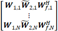
� Mode 2: Per-TRP/TRP group (port-group or resource) SD basis selection and joint/common (across N TRPs) FD basis selection. Example formulation (N = number of TRPs or TRP groups):
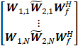
� FFS: Depending on the decision on SCI design, whether additional per-TRP/TRP-group amplitude scaling and/or co-phase is needed or not, and whether they are a part of W2s
Agreement
For the Rel-18 Type-II codebook refinement for high/medium velocities, down-select one from the following codebooks structures:
Agreement
For the Rel-18 Type-II codebook refinement for high/medium velocities, on the DD/TD basis waveforms:
� FFS: Whether Doppler-/time-domain (DD/TD) basis vector length (N4) is RRC-configured or reported by the UE
� FFS: Whether the number of selected DD/TD basis vectors (for Alt1) is RRC-configured or reported by the UE
Agreement
On the CSI reporting and measurement for the Rel-18 Type-II codebook refinement for high/medium velocities, support the assumption of the UE-side prediction
Agreement
The Rel-18 TRS-based TDCP reporting comprises stand-alone auxiliary feedback information to enable refinement of CSI reporting configuration, and/or codebook configuration parameters, and/or (to be confirmed in RAN1#110) gNB-side CSI prediction
R1-2207876������� Moderator Summary#2 on Rel-18 CSI enhancements: Round 1������� Moderator (Samsung)
From Wed session
Agreement
On the Type-II codebook refinement for CJT mTRP, down-select from the following TRP selection/determination schemes (where N is the number of cooperating TRPs assumed in PMI reporting) by RAN1#110bis-e:
� Alt1. N is gNB-configured via higher-layer (RRC) signalling
o The N configured TRPs are gNB-configured via higher-layer (RRC) signalling
o Note: only one transmission hypothesis is reported
�
Alt2.
N is UE-selected and reported as a part of CSI report where N![]() {1,..., NTRP}
{1,..., NTRP}
o N is the number of cooperating TRPs, while NTRP is the maximum number of cooperating TRPs configured by gNB
o In this case, the selection of N out of NTRP TRPs is also reported (FFS: exact reporting scheme)
o FFS: Configuration of NTRP TRPs and the value of NTRP, whether explicit or implicit
o Note: only one transmission hypothesis is reported. UE is not mandated to calculate CSI for multiple transmission hypotheses.
�
Alt3. The UE reports CSI corresponding to K
transmission hypotheses
o
The N configured TRPs per hypothesis are
gNB-configured via higher-layer (RRC) signalling
o
FFS: supported value(s) of K, and whether
the K transmission hypotheses are gNB-configured or UE-reported
o
FFS: Whether the same N value or possibly
different N values
�
Alt4. The UE reports CSI corresponding to K
transmission hypotheses where N is UE-selected and reported as a part of CSI
report where N![]()
{1,..., NTRP}
o
N is the number of cooperating TRPs per
hypothesis, while NTRP is the maximum number of cooperating TRPs configured by
gNB
o
In this case, the selection of N out of NTRP
TRPs is also reported (FFS: exact reporting scheme)
o
FFS: Configuration of NTRP TRPs and the
value of NTRP, whether explicit or implicit
o
FFS: Whether the same N value or possibly
different N values
FFS: Whether S-TRP transmission hypothesis is also reported
Agreement
On the Type-II codebook refinement for CJT mTRP, regarding W2 quantization group and Strongest Coefficient Indicator (SCI) design, for each layer, down-select one from the following alternatives by RAN1#110bis-e:
� Alt1. One group comprises one polarization across all TRPs/TRP-groups (Cgroup,phase=1, Cgroup,amp=2), one (common) SCI across all TRPs/TRP groups
� Alt2. One group comprises one polarization for one TRP/TRP-group (Cgroup,phase=N, Cgroup,amp=2N), per-TRP/TRP-group SCI
o FFS: Quantization of N strongest coefficients�
� Alt3. One group comprises one polarization for one TRP/TRP-group with a common phase reference across TRPs/TRP-groups (Cgroup,phase=1, Cgroup,amp=2N)
o FFS: SCI, per-TRP/TRP-group vs. one (common) SCI across all TRPs/TRP groups�
o FFS: Quantization of N strongest coefficients
� Alt4. For a selected TRP/TRP-group, one group comprises one polarization, and for remaining N-1 TRPs/TRP-groups, one group comprises one polarization across remaining N-1 TRPs/TRP-groups (Cgroup,amp=2+2=4), with a common phase reference across all of N TRPs/TRP-groups (Cgroup,phase=1)
o FFS: The selected TRP/TRP-group
FFS: The need for �strongest� TRP/TRP-group indicator in addition to SCI(s)
Agreement
For the Rel-18 Type-II codebook refinement for high/medium velocities, support DD/TD (compression) unit (analogous to PMI sub-band for Rel-16 codebook) as a codebook parameter.
Agreement
On the CSI reporting and measurement for the Rel-18 Type-II codebook refinement for high/medium velocities assuming the UE-side prediction, on the definition of UE-side prediction, down-select one from the following alternatives by RAN1#110bis-e:
R1-2207978������� Moderator Summary#3 on Rel-18 CSI enhancements: Round 2������� Moderator (Samsung)
Agreement
For the Rel-18 Type-II codebook for CJT mTRP based on the Rel-16 Type-II codebook, SD basis and FD basis are separate, each fully reusing the legacy Rel-16 DFT-based design.
Agreement
The Rel-18 Type-II codebook for CJT mTRP comprises refinement of the following codebooks:
Strive to maintain as much commonality between the Rel-16 and Rel-17 codebook enhancements to minimize workload.
Vivo and Lenovo raised concerns on the workload due to this agreement.
Agreement
On the CSI reporting and measurement for the Rel-18 Type-II codebook refinement for high/medium velocities, when UE-side prediction is assumed, down-select one from the following alternatives by RAN1#110bis-e:
Agreement
For the Rel-18 TRS-based TDCP reporting, down select one of the following alternatives by RAN1#110bis-e:
� AltA. Based on Doppler profile
o E.g., Doppler spread derived from the 2nd moment of Doppler power spectrum, average Doppler shifts, Doppler shift per resource, maximum Doppler shift, relative Doppler shift, etc
� AltB. Based on time-domain correlation profile
o E.g. Correlation within one TRS resource, correlation across multiple TRS resources
o Note: The correlation over one or more lags of TRS resource may be considered.� The lags may be within one TRS burst or different TRS bursts
� AltC: CSI-RS resource and/or CSI reporting setting configuration parameter(s) to assist network
o E.g. gNB configures UE with multiple choices on what to assist (e.g. two or more CSI-RS/report periodicities, or precoding schemes depending mainly on UE velocity), then UE report according to configuration; parameters correspond to CSI reporting periodicity, codebook type, etc.
Note: Different alternatives may or may not apply to different use cases.
Agreement
For the Rel-18 TRS-based TDCP reporting, the use case of �aiding gNB-side CSI prediction� is refined to �aiding gNB implementation in CSI prediction for TDD�.
Including increasing orthogonal DMRS ports for UL/DL MU-MIMO and 8 Tx UL SU-MIMO.
R1-2205749�������� On increasing the number of orthogonal DM-RS ports for MU-MIMO�������������� FUTUREWEI
R1-2205819�������� Enhanced Capacity DMRS�������������� InterDigital, Inc.
R1-2205882�������� Enhancements on DMRS in Rel-18 Huawei, HiSilicon
R1-2205921�������� DMRS enhancement for UL/DL MU-MIMO and 8 Tx UL SU-MIMO�� ZTE
R1-2205984�������� Discussion on increased number of orthogonal DMRS ports��� Spreadtrum Communications
R1-2206027�������� Discussion on DMRS enhancements������������ vivo
R1-2206106�������� Discussions on increased number of orthogonal DMRS ports�� New H3C Technologies Co., Ltd.
R1-2206190�������� On DMRS Enhancement�� Google
R1-2206212�������� Discussion of increased number of orthogonal� DMRS ports��� Lenovo
R1-2206266�������� DMRS enhancement for Rel-18 MIMO�������� OPPO
R1-2206378�������� On DMRS enhancements� CATT
R1-2206460�������� Discussion on increased number of orthogonal DMRS ports��� NEC
R1-2206573�������� Discussion on DMRS enhancement Intel Corporation
R1-2206623�������� Discussion on DMRS enhancement Xiaomi
R1-2206815�������� Views on DMRS enhancements����� Samsung
R1-2206869�������� Increased number of orthogonal DMRS ports������������� LG Electronics
R1-2206897�������� Discussion on increased number of orthogonal DMRS ports��� CMCC
R1-2206966�������� Increased number of orthogonal DMRS ports������������� Fraunhofer IIS, Fraunhofer HHI
R1-2206993�������� Increased number of orthogonal DMRS ports������������� MediaTek Inc.
R1-2207135�������� On DMRS enhancement in Rel-18� Ericsson
R1-2207218�������� Design for increased number of orthogonal DMRS ports��������� Qualcomm Incorporated
R1-2207323�������� Views on supporting increased number of orthogonal DMRS ports������� Apple
R1-2207396�������� Discussion on DMRS enhancements������������ NTT DOCOMO, INC.
R1-2207453�������� Increased number of orthogonal DMRS ports������������� Sharp
R1-2207547�������� Rel-18 UL and DL DMRS Enhancements���� Nokia, Nokia Shanghai Bell
R1-2207715������� FL summary on DMRS#1������������� Moderator (NTT DOCOMO)
From Tuesday session
Working Assumption
� To increase the number of DMRS ports for PDSCH/PUSCH, support at least Opt.1 (introduce larger FD-OCC length than Rel.15 (e.g. 4 or 6)).
o FFS: FD-OCC length for Rel.18 DMRS type 1 and type 2.
o FFS: Whether it is needed to handle potential performance issues of Opt 1. For example, study if there is performance loss in case of large delay spread scenario. If needed, how (e.g. additionally support other options).
Ericsson objected to make the above as an agreement � their preference was for no additional DMRS symbols � fine to take it as working assumption and let the work progressing further
R1-2207716������� FL summary on DMRS#2������������� Moderator (NTT DOCOMO)
From Wed session
Agreement
Agreement
Agreement
R1-2208005������� FL summary#3 on DMRS������������� Moderator (NTT DOCOMO)
From Thursday session
Agreement
For increased DMRS ports for enhanced FD-OCC, study whether/how to support DCI based switching between DMRS port(s) associated with length 2 FD-OCC and DMRS port(s) associated with length M FD-OCC (where M > 2).
Agreement
For > 4 layers PUSCH, support rank = 5,6,7,8 for both DMRS type 1/2, and for both single-symbol/double-symbol DMRS.
R1-2205750�������� SRS enhancements for TDD CJT and 8TX operation FUTUREWEI
R1-2205820�������� On SRS Enhancements for CJT and 8TX UEs������������ InterDigital, Inc.
R1-2205883�������� SRS enhancement for TDD CJT and UL 8Tx operation in Rel-18���������� Huawei, HiSilicon, LG Uplus
R1-2205922�������� SRS enhancement targeting TDD CJT and 8 TX operation������ ZTE
R1-2205985�������� Discussion on SRS enhancement targeting TDD CJT and 8 TX operation�������������� Spreadtrum Communications
R1-2206028�������� Discussion on SRS enhancement��� vivo
R1-2206191�������� On SRS Enhancement������ Google
R1-2206213�������� Discussion of SRS enhancement���� Lenovo
R1-2206267�������� SRS enhancement targeting TDD CJT and 8 TX operation������ OPPO
R1-2206379�������� On SRS enhancement for R18�������� CATT
R1-2206419�������� Views on SRS configuration targeting TDD CJT and 8 TX operation��� KDDI Corporation
R1-2206461�������� Discussion on SRS enhancement��� NEC
R1-2206574�������� Discussion on SRS enhancement in Rel-18�� Intel Corporation
R1-2206624�������� Discussion on SRS enhancements�� Xiaomi
R1-2206816�������� Views on SRS enhancements��������� Samsung
R1-2206870�������� SRS enhancement targeting TDD CJT and 8 TX operation������ LG Electronics
R1-2206898�������� Discussion on SRS enhancement targeting TDD CJT and 8 TX operation�������������� CMCC
R1-2207067�������� Discussion on SRS Enhancements for 8Tx Operation CEWiT
R1-2207219�������� SRS enhancement for TDD CJT and 8 Tx operation�� Qualcomm Incorporated
R1-2207324�������� Views on Rel-18 MIMO SRS enhancement� Apple
R1-2207397�������� Discussion on SRS enhancement��� NTT DOCOMO, INC.
R1-2207454�������� SRS enhancement targeting TDD CJT and 8 TX operation������ Sharp
R1-2207499�������� On SRS enhancements targeting TDD CJT and 8 TX operation������������� Ericsson
R1-2207548�������� SRS enhancement for TDD CJT and 8Tx operation��� Nokia, Nokia Shanghai Bell
R1-2207604�������� Considerations on precoded SRS���� Sony
R1-2207855������� FL Summary #1 on SRS enhancements���� Moderator (FUTUREWEI)
From Tuesday session
Agreement:
For Rel-18 reference signal enhancements, support and specify the following features (the agreed WID scopes apply):
Proposal 4.2-2:
For 8 Tx SRS, support both
R1-2207856������� FL Summary #2 on SRS enhancements���� Moderator (FUTUREWEI)
From Wed session
Agreement:
For 8 Tx SRS, at least support
� 8 ports in 1 SRS resource for �antennaSwitching�;
o FFS 8 ports in one or multiple SRS resources for �codebook�
Above does not imply support for 8 ports in one or multiple OFDM symbols
Agreement:
For the maximum number of SRS resource sets for SRS with 8T8R with �antennaSwitching�, keep the existing value of the maximum number of SRS resource sets (as provided in Rel-17 antenna switching nTnR).
R1-2208014������� FL Summary #3 on SRS enhancements���� Moderator (FUTUREWEI)
From Thursday session
Agreement
For an 8-port SRS resource in an SRS resource set with usage antennaSwitching (i.e., for 8T8R antenna switching), the 8-port SRS resource is transmitted in at least one OFDM symbol.
� FFS: the resource transmitted in multiple OFDM symbols where different ports are mapped to different symbols.
Agreement
For SRS resource set(s) with usage �nonCodebook� support 8 1-port SRS resources in one or multiple OFDM symbols.
� Note: The maximum number of simultaneous SRS resources is determined via UE-capability signalling.
Final summary in R1-2208015.
R1-2205821�������� Discussion on Uplink Multi-panel Transmission�������� InterDigital, Inc.
R1-2205884�������� Discussion on UL precoding indication for multi-panel transmission���� Huawei, HiSilicon
R1-2205923�������� Enhancements on UL precoding indication for multi-panel transmission������������� ZTE
R1-2205986�������� Discussion on UL precoding indication for multi-panel transmission���� Spreadtrum Communications
R1-2206029�������� Discussion on UL precoding indication for multi-panel transmission���� vivo
R1-2206111�������� Considerations on UL for multi-panel transmission��� Sony
R1-2206162�������� Discussion on UL precoding indication for multi-panel transmission���� Fujitsu
R1-2206192�������� On Simultaneous Multi-Panel Transmission Google
R1-2206214�������� UL precoding indication for multi-panel transmission Lenovo
R1-2206268�������� Transmission scheme and UL precoding indicaton for multi-panel transmission�������������� OPPO
R1-2206380�������� Discussion on UL precoding indication for multi-panel transmission���� CATT
R1-2206465�������� Discussion on UL precoding indication for multi-panel transmission���� NEC
R1-2206575�������� UL precoding indication for multi-panel transmission (STxMP)������������ Intel Corporation
R1-2206625�������� Enhancements on multi-panel uplink transmission����� Xiaomi
R1-2206817�������� Views on UL precoding indication for STxMP����������� Samsung
R1-2207693�������� UL precoding indication for multi-panel transmission LG Electronics��� (rev of R1-2206871)
R1-2206899�������� Discussion on UL precoding indication for multi-panel transmission���� CMCC
R1-2206997�������� Simultaneous transmission across multiple UE panels MediaTek Inc.
R1-2207112�������� UL precoding indication for multi-panel transmission Ericsson
R1-2207145�������� On UL precoding indication for simultaneous multi-panel transmission Fraunhofer IIS, Fraunhofer HHI
R1-2207220�������� Simultaneous multi-panel transmission�������� Qualcomm Incorporated
R1-2207325�������� Views on UL precoding indication for multi-panel simultaneous PUSCH transmissions������ Apple
R1-2207761�������� Discussion on multi-panel transmission������� NTT DOCOMO, INC.������ (rev of R1-2207398)
R1-2207455�������� Views on UL multi-panel transmission�������� Sharp
R1-2207549�������� Precoder Indication for Multi-Panel UL Transmission Nokia, Nokia Shanghai Bell
R1-2207698������� Summary #1 on Rel-18 STxMP��� Moderator (OPPO)
R1-2207699������� Summary #2 on Rel-18 STxMP��� Moderator (OPPO)
From Thursday session
Working assumption
Support the following schemes for STxMP PUSCH transmission in single-DCI based
mTRP system in Rel-18:
For schemes other than
SDM, final decision to support or not will be made in RAN1#110bis-e.
Agreement
For single-DCI based STxMP PUSCH
SDM scheme, support the layer combinations of {1+1, 1+2, 2+1 and 2+2} for single CW case.
Agreement
To enhance the DMRS port indication for SDM scheme of STxMP PUSCH transmission in single-DCI based mTRP system, study the following aspects:
Agreement
Study and evaluate STxMP PUCCH based on the following:
� For single-DCI based STxMP PUCCH transmissions, companies to provide the detailed description of the scheme being evaluated along with evaluation results in contribution.
� For multi-DCI based STxMP PUCCH transmissions, transmitting two PUCCH resources with independent UCI payload to different TRPs with different UE panels that are fully or partially overlapping in time domain and partially/fully/non-overlapping in frequency domain can be considered.
� Note: Companies can reuse the EVM assumptions of Rel-18 STxMP as agreed in RAN1#109-e (other than the parameters that are specific to PUSCH) as well as Rel-17 EVM for PUCCH as agreed in RAN1#102-e (PUCCH format, # of RBs/symbols, UCI payload, and Frequency hopping as shown below).
o Baseline scheme can be Rel-15 PUCCH or Rel-17 mTRP PUCCH repetition.
|
Parameters |
Potential values |
|
Baseline scheme |
Rel-15 PUCCH or Rel-17 mTRP PUCCH repetition |
|
PUCCH format |
Format 1 and 3. Other PUCCH Formats can be optionally considered. |
|
# of RBs/symbols |
PUCCH Format 1: 4 symbols, 1 RB PUCCH Format 3: 4 and 8 symbols, 1 RB Other combinations are not precluded. |
|
UCI payload |
2 bits for PUCCH Format 1 (and Format 0, if considered). Companies to report assumptions on other PUCCH Formats |
|
Frequency hopping |
Reported by companies |
To support up to 4 or more layers per UE in UL targeting CPE/FWA/vehicle/industrial devices.
R1-2205822�������� SRI/TPMI Enhancement for 8TX UE����������� InterDigital, Inc.
R1-2205885�������� Discussion on SRI/TPMI enhancement for enabling 8 TX UL transmission�������������� Huawei, HiSilicon
R1-2205924�������� SRI/TPMI enhancement for enabling 8 TX UL transmission��� ZTE
R1-2205987�������� Discussion on SRI/TPMI enhancement for enabling 8 TX UL transmission�������������� Spreadtrum Communications
R1-2206030�������� Discussion on enabling 8 TX UL transmission����������� vivo
R1-2206112�������� Discussion on enhancement for 8Tx UL transmission Sony
R1-2206193�������� On SRI/TPMI Indication for 8Tx Transmission��������� Google
R1-2206215�������� SRI/TPMI enhancement for enabling 8TX UL transmission���� Lenovo
R1-2206269�������� SRI TPMI enhancement for 8 TX UL transmission��� OPPO
R1-2206381�������� On codebook and SRI/TPMI enhancement for UL 8 TX����������� CATT
R1-2206462�������� Discussion on SRI/TPMI enhancement�������� NEC
R1-2206576�������� Discussion on enhancement for 8Tx UL transmission Intel Corporation
R1-2206626�������� Enhancements on 8Tx uplink transmission�� Xiaomi
R1-2206818�������� Views on TPMI/SRI enhancements for 8Tx UL transmission�� Samsung
R1-2206872�������� SRI/TPMI enhancement for enabling 8 TX UL transmission��� LG Electronics
R1-2206900�������� Discussion on SRI/TPMI enhancement for enabling 8 TX UL transmission�������������� CMCC
R1-2206994�������� SRI/TPMI enhancement for enabling 8 TT UL transmission��� MediaTek Inc.
R1-2207163�������� SRI/TPMI Enhancement for Enabling 8 TX UL Transmission Ericsson
R1-2207221�������� Enhancements for 8 Tx UL transmissions���� Qualcomm Incorporated
R1-2207326�������� Views on SRI/TPMI enhancement for enabling 8 TX UL transmission� Apple
R1-2207399�������� Discussion on 8 TX UL transmission����������� NTT DOCOMO, INC.
R1-2207456�������� Views on 8 TX UL transmission���� Sharp
R1-2207550�������� UL enhancements for enabling 8Tx UL transmission Nokia, Nokia Shanghai Bell
R1-2207725������� FL Summary on SRI/TPMI Enhancements; First Round��� Moderator (InterDigital)
From Monday session
Agreement
� 8TX PUSCH is supported in Rel-18
Agreement
For a 8TX PUSCH, at least support
Note: The above does not restrict the Ng for the non-coherent case
Agreement
For evaluation purpose of codebook alternatives when a precoder based on Rel-15 DL Type I is used, following oversampling ratios are assumed
� (O1, O2) = (1,1), (2,1), (2,2)
� Note: Other values may be used and reported by companies
� Note: When deciding the supported O1, O2 combination, the signalling overhead, performance, UE complexity, etc should be considered
Agreement
RAN1 further studies Alt1b and Alt2a for down-selection of one of the two in RAN1 meeting #110b-e.
R1-2207726������� FL Summary on SRI/TPMI Enhancements; Second Round Moderator (InterDigital)
From Wed session
Agreement
Support up to X layers for codebook and non-codebook UL transmission for 8TX UE where X=4, 8 is determined based on separate UE capability
The above applies only with regards to the work scope of this agenda item.
Agreement
For SRS configuration for non-codebook UL transmission for an 8TX UE, down-select from
R1-2208012������� FL Summary on SRI/TPMI Enhancements; Third Round� Moderator (InterDigital)
From Thursday session
Agreement
Study low overhead solutions for SRI and/or transmitter precoder matrix indication for codebook-based, and SRI indication for non-codebook-based UL transmission by an 8TX UE,
� FFS using single or separate (exiting or new) fields for the indication, other solutions are not precluded.
� Note: Low overhead schemes for study include those using Rel-15 SRI/TPMI indication mechanisms
R1-2208013�������� Recommended Direction on SRI/TPMI Enhancements for RAN1#110b-e�������������� Moderator (InterDigital)
Please refer to RP-213598 for detailed scope of the WI.
Including extension for indication of multiple DL/UL TCI states, simultaneous multi-panel UL transmission, and power control for UL single DCI.
R1-2208373�������� Unified TCI framework extension for multi-TRP������� FUTUREWEI
R1-2208439�������� Discussion on unified TCI framework extension for multi-TRP������������� Huawei, HiSilicon
R1-2208493�������� On Unified TCI Extension for MTRP����������� InterDigital, Inc.
R1-2208502�������� Enhancements on unified TCI framework extension for multi-TRP������� ZTE
R1-2208539�������� Discussion on unified TCI framework extension for multi-TRP������������� Spreadtrum Communications
R1-2208626�������� Discussion on unified TCI framework extension for multi-TRP������������� vivo
R1-2208676�������� Unified TCI framework extension for multi-TRP������� Ericsson
R1-2208702�������� Discussion on unified TCI framework extension for multi-TRP operation����������� TCL Communication Ltd.
R1-2208740�������� Discussion of unified TCI framework for multi-TRP� Lenovo
R1-2208792�������� Unified TCI framework extension for multi-TRP������� OPPO
R1-2208891�������� Unified TCI framework extension for multi-TRP/panel����������� LG Electronics
R1-2208945�������� On unified TCI framework extension for multi-TRP operation CATT
R1-2209008�������� Discussion on unified TCI extension for MTRP��������� Fujitsu
R1-2209039�������� Unified TCI Framework for Multi-TRP������� Intel Corporation
R1-2209138�������� Discussion on unified TCI framework extension for multi-TRP������������� NEC
R1-2209165�������� Discussion on unified TCI framework extension for multi-TRP������������� Transsion Holdings
R1-2209256�������� Unified TCI framework extension for multi-TRP������� xiaomi
R1-2209320�������� Discussion on unified TCI framework extension for multi-TRP������������� CMCC
R1-2209379�������� Unified TCI framework extension for multi-TRP������� Sharp
R1-2209414�������� Discussion on unified TCI framework extension for multi-TRP������������� FGI
R1-2209492�������� Unified TCI framework extension for multi-TRP������� MediaTek Inc.
R1-2209540�������� Discussion on unified TCI framework extension for multi-TRP������������� Google
R1-2209547�������� Multi-TRP enhancements for the unified TCI framework�������� Fraunhofer IIS, Fraunhofer HHI
R1-2209568�������� Views on unified TCI framework extension for multi-TRP������ Apple
R1-2209712�������� Views on unified TCI extension focusing on m-TRP� Samsung
R1-2209888�������� Discussion on unified TCI framework extension for multi-TRP������������� NTT DOCOMO, INC.
R1-2209967�������� Extension of unified TCI framework for mTRP���������� Qualcomm Incorporated
R1-2210018�������� Unified TCI framework extension for multi-TRP������� PANASONIC
R1-2210029�������� Discussion on unified TCI framework extension for multi-TRP������������� ITRI
R1-2210061�������� Unified TCI framework extension for multi-TRP������� Nokia, Nokia Shanghai Bell
R1-2210104�������� Discussion on Unified TCI framework extension for multi-TRP������������ CEWiT
[110bis-e-R18-MIMO-01] � Darcy (MediaTek)
Email discussion on unified TCI framework extension for multi-TRP by October 19
- Check points: October 14, October 19
R1-2210243������� Moderator summary on extension of unified TCI framework (Round 0)�������������� Moderator (MediaTek Inc.)
Presented in Oct 10th GTW session
R1-2210380������� Moderator summary on extension of unified TCI framework (Round 1)�������������� Moderator (MediaTek Inc.)
From Oct 13th GTW session
Conclusion
On unified TCI framework extension in Rel-18, there is no consensus to support simultaneous configuration of both joint and separate DL/UL TCI modes in a serving cell.
Conclusion
On unified TCI framework extension in Rel-18, there is no consensus to support separate RRC-configured TCI state list(s) for each of TRPs.
Agreement:
On unified TCI framework extension for M-DCI based MTRP:
� The existing TCI field in a DCI format 1_1/1_2 (with or without DL assignment) associated with one coresetPoolIndex value can indicate the joint/DL/UL TCI state(s) specific to the same coresetPoolIndex value
o FFS: The UE shall apply the indicated joint/DL/UL TCI state(s) specific to a coresetPoolIndex value to channel(s)/signal(s) that have explicit or implicit association with the same coresetPoolIndex value
� A coresetPoolIndex value field is included in TCI state activation command (MAC-CE) to indicate that the mapping between the activated TCI state(s) and the TCI codepoint(s) is specific to which coresetPoolIndex value
Agreement:
On unified TCI framework extension for S-DCI based MTRP, to inform the association with the joint/DL TCI state(s) indicated by DCI/MAC-CE for PDCCH repetition, PDCCH-SFN, and PDCCH w/o repetition/SFN, support the following:
� Use RRC configuration to inform that the UE shall apply the first one, the second one, both, or none of the joint/DL TCI states indicated by DCI/MAC-CE to a CORESET or a group of CORESETs (if CORESET group configuration is supported)
Decision: As per email posted on Oct 13th,
Agreement
On unified TCI framework extension for M-DCI based MTRP:
� For a serving cell configured with joint DL/UL TCI mode, one joint TCI state can be mapped to a TCI codepoint of the existing TCI field in a DCI format 1_1/1_2 (with or without DL assignment)
� For a serving cell configured with separate DL/UL TCI mode, a DL TCI state, an UL TCI state, or a pair of DL and UL TCI states can be mapped to a TCI codepoint of the existing TCI field in a DCI format 1_1/1_2 (with or without DL assignment)
Agreement
On unified TCI framework extension for S-DCI based MTRP, down-select one alternative from the followings in RAN1#111 for PUSCH transmission scheduled/activated by a DCI format 0_1/0_2:
� Alt1: Use an indicator field (could be reusing an existing DCI field or introducing a new DCI field) in the DCI format 0_1/0_2 to inform which joint/UL TCI state(s) indicated by MAC-CE/DCI the UE shall apply to PUSCH transmission scheduled/activated by the DCI format 0_1/0_2
� Alt2: PUSCH transmission scheduled/activated by the DCI format 0_1/0_2 follows the spatial domain transmission filter(s) used for the SRS resource(s) indicated by the DCI format 0_1/0_2
o FFS : PL-RS(s), and UL PC parameter setting(s) (including P0, alpha, and closed loop index) for the PUSCH
Agreement
On unified TCI framework extension for S-DCI based MTRP, down-select one alternative from the followings in RAN1#111 for PUCCH transmission:
� Alt1: Use RRC configuration to inform the association between the indicated joint/UL TCI state(s) and a PUCCH resource/ group
� Alt2: Use RRC configuration to inform the association between a CORESET group and a PUCCH resource/group, and the indicated joint/UL TCI state(s) associated with the CORESET group applies to the PUCCH resource/group associated with the same CORESET group
� Alt3: Use MAC-CE to inform the association between the indicated joint/UL TCI state(s) and a PUCCH resource/group
� Note: the association indicates whether the UE shall apply the first one, the second one, or both of the joint/UL TCI states indicated by DCI/MAC-CE to a PUCCH resource/group
Decision: As per email posted on Oct 18th,
Agreement
On unified TCI framework extension, up to 2 joint TCI states can be indicated by MAC-CE/DCI and applied to CJT-based PDSCH reception (PDSCH-CJT) in a BWP/CC configured with joint DL/UL TCI mode
� Support of 1 or 2 indicated joint TCI states for PDSCH-CJT is up to UE capability
� FFS: QCL type(s)/assumption(s) of the indicated joint TCI state(s) applied to PDSCH-CJT
� Note: On how to inform UE to apply which indicated joint TCI state(s) to target channel(s)/signal(s) in the BWP/CC, it is discussed individually in AI 9.1.1.1
R1-2210597������� Moderator summary on extension of unified TCI framework (Round 2)�������������� Moderator (MediaTek Inc.)
From Oct 19th GTW session
Agreement
On unified TCI framework extension for M-DCI based MTRP:
� The UE shall apply the indicated joint/DL TCI state specific to a coresetPoolIndex value to PDCCH on a CORESET that is associated with the same coresetPoolIndex value
� The UE shall apply the indicated joint/DL TCI state specific to a coresetPoolIndex value to PDSCH scheduled/activated by PDCCH on a CORESET that is associated with the same coresetPoolIndex value
� FFS: Other channel(s)/signal(s) that has explicit or implicit association with a coresetPoolIndex value
� FFS: Other channel(s)/signal(s) that doesn�t have association with a coresetPoolIndex value
Above are applicable to the CORESET(s) that is configured/allowed to follow the indicated joint/DL TCI state
FFS: The configuration/rule to configure/allow CORESET(s) to follow the indicated joint/DL TCI state, including the option to reuse the same configuration/rule as in Rel-17 unified TCI framework
Agreement
On unified TCI framework extension, study the following enhancements for TRP-specific BFR:
� Implicit BFD-RS determination based on the indicated joint/DL TCI states for S-DCI based MTRP
� Enhancement to beam update after NW response to TRP-specific BFR request
Decision: As per email posted on Oct 20th,
Agreement
On unified TCI framework extension for S-DCI based MTRP , down-select one alternative from the followings in RAN1#111:
Note: It has been agreed to use the existing TCI field for TCI state indication for S-DCI based MTRP in RAN1#109e
Note: The term TRP is used only for discussion purpose in RAN1 and whether/how to capture this is FFS
FFS: The behavior if the UE receives a beam indication DCI that indicates joint/DL/UL TCI state(s) for one TRP
R1-2208374�������� Enhancements to support two TAs for multi-DCI������ FUTUREWEI
R1-2208440�������� Study on TA enhancement for UL M-TRP transmission���������� Huawei, HiSilicon
R1-2208460�������� Discussion on two TAs for multi-DCI based on multi-TRP operation���� TCL Communication Ltd.
R1-2208494�������� Multiple TA for MTRP Operation� InterDigital, Inc.
R1-2208503�������� TA enhancement for multi-DCI������ ZTE
R1-2208540�������� Discussion on two TAs for multi-DCI based multi-TRP����������� Spreadtrum Communications
R1-2208627�������� Discussion on two TAs for multi-DCI-based multi-TRP operation�������� vivo
R1-2208677�������� Two TAs for multi-DCI��� Ericsson
R1-2208741�������� Discussion of two TAs for multi-DCI UL transmission������������ Lenovo
R1-2208793�������� Two TAs for multi-DCI��� OPPO
R1-2208892�������� Two TAs for multi-TRP/panel�������� LG Electronics
R1-2208946�������� On Two TAs for UL multi-DCI multi-TRP operation CATT
R1-2209040�������� On two TAs for multi-DCI Intel Corporation
R1-2209139�������� Discussion on two TAs for multi-DCI���������� NEC
R1-2209166�������� Discussion on two TAs for multi-DCI based multi-TRP operation��������� Transsion Holdings
R1-2209257�������� Discussion on two TAs for multi-TRP operation�������� xiaomi
R1-2209321�������� Discussion on two TAs for multi-DCI���������� CMCC
R1-2209380�������� Two TAs for multi-DCI��� Sharp
R1-2209493�������� UL Tx Timing Management for MTRP Operation����� MediaTek Inc.
R1-2209541�������� Discussion on two TAs for multi-DCI���������� Google
R1-2209569�������� Two TAs for multi-DCI Uplink Transmissions���������� Apple
R1-2209713�������� Views on two TAs for m-DCI��������� Samsung
R1-2209889�������� Discussion on two TAs for multi-DCI���������� NTT DOCOMO, INC.
R1-2209968�������� Supporting two TAs for multi-DCI based mTRP�������� Qualcomm Incorporated
R1-2210062�������� Two TAs for UL multi-DCI multi-TRP operation������ Nokia, Nokia Shanghai Bell
[110bis-e-R18-MIMO-02] � Siva (Ericsson)
Email discussion on two TAs for multi-DCI by October 19
- Check points: October 14, October 19
R1-2210304������� Moderator Summary #1 on Two TAs for multi-DCI����������� Moderator (Ericsson)
From Oct 10th GTW session
Agreement
For multi-DCI multi-TRP operation with two TAs in a CC, two DL reference timings are supported where each DL reference timing is associated with one TAG
� baseline assumption is that the Rx timing difference between the two DL reference timings is no larger than CP length
� as an optional UE capability, Rx timing difference between the two DL reference timings can be assumed to be larger than CP length
o FFS: the maximum Rx timing difference (could be up to RAN4)
o Other than UE capability details and relevant configuration, no additional RAN1 specification enhancement specific for this case is expected
Decision: As per email decision posted on Oct 12th,
Agreement
Multi-DCI multi-TRP operation with two TAs is supported for Rel-15/16/17 TCI frameworks and unified TCI framework extension discussed in 9.1.1.1 as well as UL beam indication via spatial relation.
Decision: As per email decision posted on Oct 15th,
Agreement
For inter-cell multi-DCI based Multi-TRP operation with two TA enhancement, support one of the alternatives (down selection to be done in RAN1#111):
R1-2210468������� Moderator Summary #2 on Two TAs for multi-DCI����������� Moderator (Ericsson)
From Oct 18th GTW session
Agreement
For multi-DCI based inter-cell Multi-TRP operation with two TA enhancement, support PRACH configuration associated with additional configured PCIs different from the PCI of the serving cell.
Agreement
For multi-DCI based inter-cell Multi-TRP operation with two TA enhancement, support a mechanism to determine which PRACH configuration (i.e., RACH configuration corresponding to serving cell PCI or an additional PCI) to be used in the RACH procedure triggered by PDCCH order
Agreement
For multi-DCI based Multi-TRP operation with two TA enhancement, support one of the following alternatives in RAN1#111:
� Alt 1: PDCCH order sent by one TRP triggers RACH procedure towards the same TRP
o Note: with Alt 1, PDCCH order sent by one TRP triggering RACH procedure towards another TRP is not allowed
� Alt 2: PDCCH order sent by one TRP triggers RACH procedure towards either the same TRP or a different TRP
o This does not preclude PDCCH order triggering two RACH procedures for two TRPs
Decision: As per email decision posted on Oct 20th,
Agreement
For associating TAGs to target UL channels/signals for multi-DCI based multi-TRP operation, the four options agreed in RAN1#110bis-e are refined as below (down-selection of one or a combination of the options to be performed in RAN1#111):
Agreement
For multi-DCI based Multi-TRP operation with two TA enhancement, support enhancements related to indicating TAG ID via absolute TA command:
� FFS: whether the indication is implicit or explicit
� Detailed indication schemes are FFS
� This does not preclude indication of two TAG IDs (if supported)
� Note: This applies at least to MSGB in case of C-RNTI
Conclusion
For multi-DCI based Multi-TRP operation with two TA enhancement, it cannot always be assumed that both TRPs have knowledge of the overlapping region between transmissions corresponding to the two TAs.
Agreement
For intra-cell multi-DCI based Multi-TRP operation with two TA enhancement, support at least one of the following alternatives (down selection to be done in RAN1#111):
Note: If Alt 1 or Alt 2 is down-selected, then it does not preclude indication of two TAG IDs (if supported)
Including CSI enhancement for high/medium UE velocities and coherent JT (CJT).
R1-2208441�������� CSI enhancement for coherent JT and mobility���������� Huawei, HiSilicon
R1-2208495�������� Enhanced CSI for CJT and High Doppler Operations InterDigital, Inc.
R1-2208504�������� CSI enhancement for high/medium UE velocities and CJT������ ZTE
R1-2208541�������� Discussion on CSI enhancement for high/medium UE velocities and coherent JT�������������� Spreadtrum Communications
R1-2208628�������� Discussion on CSI enhancement for high-medium UE velocities and coherent JT vivo
R1-2208742�������� Discussion of CSI enhancement for high speed UE and coherent JT������ Lenovo
R1-2208794�������� CSI enhancement for high/medium UE velocities and coherent JT�������� OPPO
R1-2208872�������� On CSI Enhancement������� Google
R1-2208893�������� Potential CSI enhancement for high/medium UE velocities and coherent JT�������� LG Electronics
R1-2208947�������� Discussion on CSI enhancements��� CATT
R1-2209041�������� On CSI enhancements������ Intel Corporation
R1-2209090�������� Further considerations on CSI enhancement for high/medium UE velocities and CJT�������������� Sony
R1-2209140�������� Discussion on CSI enhancement���� NEC
R1-2209247�������� Discussion on CSI enhancement���� Mavenir
R1-2209258�������� Discussion on CSI enhancement for high/medium UE velocities and CJT�������������� xiaomi
R1-2209322�������� Discussion on CSI enhancement for high/medium UE velocities and� CJT�������������� CMCC
R1-2209381�������� CSI enhancement Sharp
R1-2209494�������� CSI enhancement MediaTek Inc.
R1-2209545�������� CSI enhancements for medium UE velocities and coherent JT Fraunhofer IIS, Fraunhofer HHI
R1-2209570�������� Views on Rel-18 MIMO CSI enhancement�� Apple
R1-2209714�������� Moderator summary on Rel-18 CSI enhancements���� Moderator (Samsung)
R1-2209715�������� Summary of OFFLINE discussion on Rel-18 MIMO CSI��������� Moderator (Samsung)
R1-2210241�������� Views on CSI enhancements���������� Samsung������������� (rev of R1-2209716)
R1-2209793�������� Views on CSI Enhancements for CJT����������� AT&T
R1-2209852�������� On CSI enhancements for Rel-18 NR MIMO evolution����������� Ericsson
R1-2209890�������� Discussion on CSI enhancement���� NTT DOCOMO, INC.
R1-2209969�������� CSI enhancements for high/medium UE velocities and Coherent-JT����� Qualcomm Incorporated
R1-2210063�������� CSI enhancement for high/medium UE velocities and CJT������ Nokia, Nokia Shanghai Bell
R1-2210105�������� Discussion on CSI Enhancements for high/medium UE velocities and coherent JT�������������� CEWiT
[110bis-e-R18-MIMO-03] � Eko (Samsung)
Email discussion on CSI enhancement by October 19
- Check points: October 14, October 19
R1-2209714������� Moderator Summary on Rel-18 CSI enhancements������������� Moderator (Samsung)
From Oct 10th GTW session
Agreement
On the Type-II codebook refinement for CJT mTRP, following legacy (Rel-16 regular eType-II and Rel-17 PS FeType-II), for a given CSI-RS resource:
Note: The supported value(s) for each of the defined parameters are to be discussed separately (e.g. possibilities of adding new or removing existing value(s) in addition to those supported by legacy specification).
Agreement
On the SD basis selection for Type-II codebook refinement for CJT mTRP, following legacy (Rel-16 regular eType-II and Rel-17 PS FeType-II), SD basis selection is per CSI-RS-resource.
o Alt1. Per-CSI-RS-resource Ln parameter
�
TBD:
Whether {Ln, n=1, ..., N} are higher-layer
configured by gNB, or the total ![]() �is higher-layer
configured by gNB while {Ln, n=1, ..., N} are
reported by the UE
�is higher-layer
configured by gNB while {Ln, n=1, ..., N} are
reported by the UE
o Alt2. gNB configures a common L parameter for all N CSI-RS resources via higher-layer signaling
FFS: Study on additional optimization for collocated multi-panel scenario
Agreement
On the Type-II codebook refinement for CJT mTRP, following legacy (Rel-16 regular eType-II and Rel-17 PS FeType-II), regarding the location of non-zero coefficients (NZCs) indicated by bitmap (following legacy mechanism), for each layer, support separate bitmap per each CSI-RS resource
�
Total
size = ![]() �where
�where ![]() �is the bitmap size for
CSI-RS resource n
�is the bitmap size for
CSI-RS resource n
o TBD:
Whether ![]() �(
�(![]() �for mode 2) analogous
to legacy, or further reduction of bitmap size is supported.
�for mode 2) analogous
to legacy, or further reduction of bitmap size is supported.
o FFS:
Depending on the outcome of other issues, whether ![]() �or�
�or� ![]()
� FFS: Per-CSI-RS-resource NNZC (number of NZCs) constraint vs. joint NNZC constraint across N CSI-RS-resources
Agreement
For the Rel-18 Type-II codebook refinement for CJT mTRP, the constraint on the maximum number of non-zero coefficients (NZCs) per-layer (K0) is defined jointly across all N CSI-RS resources
Agreement
For the Rel-18 Type-II codebook refinement for CJT mTRP,
Agreement
On the Type-II codebook refinement for CJT mTRP, regarding W2 quantization group and Strongest Coefficient Indicator (SCI) design, for each layer:
o Alt1. One group comprises one polarization across all N CSI-RS resources (Cgroup,phase=1, Cgroup,amp=2)
� FFS: Amplitude quantization table considering transmission power difference between multiple TRPs
� For each of the amplitude groups (other than the group associated with the SCI), the reference amplitude is reported
o Alt3. One group comprises one polarization for one CSI-RS resource with a common phase reference across N CSI-RS resources (Cgroup,phase=1, Cgroup,amp=2N)
� For each of the (2N�1) amplitude groups (other than the group associated with the SCI), the reference amplitude is reported
FFS: The need for �strongest� TRP/TRP-group indicator in addition to the SCI
Decision: As per email decision posted on Oct 11th,
Agreement
For the Rel-18 Type-II codebook for CJT mTRP, the switching between mode-1 and mode-2 is gNB-initiated via RRC signalling.
Agreement
For the Rel-18 Type-II codebook refinement for high/medium velocities, support RI={1,2,3,4}.
Agreement
On the CSI reporting and measurement for the Rel-18 Type-II codebook refinement for high/medium velocities, when UE-side prediction is assumed, support UE �predicting� channel/CSI after slot l where the location of slot l is configured (from multiple candidate values) by gNB via higher-layer signalling
Note: Per legacy behavior, the legacy CSI reference resource, i.e., (n � nCSI,ref ), is reused for locating the last CSI-RS occasion used for a CSI report.
For a UE that supports UE-side prediction, the support of l = (n � nCSI,ref ) is UE optional.
Agreement
For the Type-II codebook refinement for high/medium velocities, down-select from the following alternatives:
� Alt1. Q different 2-dimentional bitmaps are introduced for indicating the location of the NZCs, where the qth (q=1,�., Q) 2-dimentional bitmap corresponds to qth selected DD basis vector
o The number of selected DD basis vectors is denoted as Q
o This implies that for each layer, the location of NZCs in SD-FD can be different for different selected DD basis vectors.
� Alt2. A DD-basis-common per-layer 2-dimensional bitmap for indicating the location of NZCs used in Rel-16/17 Type-II is used
o This implies that for each layer, the location of NZCs in SD-FD is common across all the Q selected DD basis vectors
FFS: Further overhead reduction on bitmap(s).
FFS: Whether the number of NZCs is upper bounded across all DD basis vectors or per DD basis vector.
Agreement
For the Rel-18 Type-II codebook refinement for high/medium velocities, support the following codebook structure where N4 is gNB-configured via higher-layer signaling:
�
For N4=1,
Doppler-domain basis is the identity (no Doppler-domain compression) reusing
the legacy ![]() ,
, ![]() , and
, and ![]() , e.g.
, e.g. ![]()
�
For N4>1,
Doppler-domain orthogonal DFT basis commonly selected for all SD/FD bases
reusing the legacy ![]() �and
�and ![]() , e.g.
, e.g. ![]()
o Only Q (denoting the number of selected DD basis vectors) >1 is allowed
o TBD (by RAN1#110bis): whether rotation is used or not
o FFS: identical or different rotation factors for different SD components
o FFS: Whether Q is RRC-configured or reported by the UE
Note: Detailed designs for SD/FD bases including the associated UCI parameters follow the legacy specification
FFS:
Whether one CSI reporting instance includes multiple ![]() �and a single
�and a single ![]() �and
�and ![]() �report.
�report.
Decision: As per email decision posted on Oct 12th,
Agreement
On the SD basis selection for Type-II codebook refinement for CJT mTRP, support the following on the L parameter:
� Per-CSI-RS-resource Ln parameter
o TBD: Whether {Ln,
n=1, ..., N} are higher-layer configured by gNB, or the total ![]() �is higher-layer
configured by gNB while {Ln, n=1, ..., N} are
reported by the UE, one L configured and {Ln} determined from
configured L
�is higher-layer
configured by gNB while {Ln, n=1, ..., N} are
reported by the UE, one L configured and {Ln} determined from
configured L
o FFS: The value of Ln is taken from a pre-defined set
Conclusion
On the Type-II codebook refinement for CJT mTRP, regarding W2 quantization group and Strongest Coefficient Indicator (SCI) design, there is no consensus on supporting �strongest� CSI-RS resource indicator in addition to the agreed SCI.
Agreement
For the Rel-18 Type-II codebook refinement for CJT mTRP, following legacy, support both aperiodic and semi-persistent CSI reporting on PUSCH.
Conclusion
On the usage of CSI reporting and measurement for the Rel-18 Type-II codebook refinement for high/medium velocities, there is no consensus in supporting any specification enhancement for the following assumptions:
� Legacy UE procedure for CSI measurement/calculation (equivalent to the combination of l = (n � nCSI,ref ) and WCSI=1)
� gNB-side prediction
o Note: This doesn�t preclude any gNB implementation
Agreement
For the Type-II codebook refinement for high/medium velocities, only CSI reporting over PUSCH is supported
� Following legacy, support both aperiodic and semi-persistent CSI reporting on PUSCH.
Agreement
For the Type-II codebook refinement for high/medium velocities, the selection of DD basis vectors is layer-specific
� The number of selected DD basis vector (denoted as Q) is layer-common
Decision: As per email decision posted on Oct 13th,
Agreement
For the Rel-18 TRS-based TDCP reporting, down select one of the following alternatives by RAN1#110bis-e:
Note: Different alternatives may or may not apply to different use cases
FFS: The need for a measure of confidence level in the TDCP report, and/or UE behaviour when the quality of TDCP measurement is not sufficiently high
FFS: TDCP parameter(s) signaled with respect to each alternative
R1-2210370������� Moderator summary#2 on Rel-18 CSI enhancements: Round 1������� Moderator (Samsung)
From Oct 13th GTW session
Agreement
� On the CSI reporting and measurement for the Rel-18 Type-II codebook refinement for high/medium velocities, support the following CSI-RS resource types/structures for CMR:
� Time-domain behaviour for NZP CSI-RS resource: periodic (P), semi-persistent (SP), aperiodic (AP)
o FFS: Whether to introduce constraints on allowed configuration
� Down select from the following:
o Alt1. Support K>1 NZP CSI-RS resources, received via a single triggering instance, for aperiodic (AP) -CSI-RS-based channel measurement in a same CSI-RS resource set where the separation between 2 consecutive AP-CSI-RS resources is m slot(s):
o Alt2. Support one NZP CSI-RS resource in a CSI-RS resource set, where K>1 occasions are received via a single triggering instance, for aperiodic (AP)-CSI-RS-based channel measurement where the separation between 2 consecutive AP-CSI-RS resources is m slot(s).
o For any of the alternatives:
� No CRI is reported
� FFS: Details, e.g., supported value(s) of K, m, other use cases for the AP-CSI-RS resources (e.g., for training filter coefficients, prediction or performance monitoring)
� Support only one NZP CSI-RS resource for P or SP-CSI-RS-based channel measurement
Agreement
On the Type-II codebook refinement
for CJT mTRP, the selection of N CSI-RS resources is performed by UE and
reported as a part of CSI report where N![]() {1,..., NTRP}
{1,..., NTRP}
Note: This agreement does not impact the decision on Ln being configured by gNB or selected by UE
Note: per WID and previous agreement, the candidate values for NTRP of are 1, 2, 3, and 4.
Note: only one transmission hypothesis is reported. UE is not mandated to calculate CSI for multiple transmission hypotheses.
Decision: As per email decision posted on Oct 13th,
Agreement
For the Rel-18 Type-II codebook refinement for high/medium velocities, when N4>1, if multiple candidates of Q value are supported, the value of Q is gNB-configured via higher-layer (RRC) signalling.
Conclusion:
For the Rel-18 TRS-based TDCP reporting, there is no consensus in supporting periodic, semi-persistent, and event-triggered/UE-initiated TDCP reporting.
Decision: As per email decision posted on Oct 14th,
Agreement
On the Type-II codebook refinement for CJT mTRP, regarding W2 quantization group, for each layer:
R1-2210507�������� Moderator summary#3 on Rel-18 CSI enhancements: Round 2 Moderator (Samsung)
Decision: As per email decision posted on Oct 17th,
Agreement
For the Rel-18 Type-II codebook refinement for CJT mTRP, also support a constraint on the total number of non-zero coefficients (NZCs) summed across all layers:
Agreement
On the SD basis selection for Type-II codebook refinement for CJT mTRP, on the L parameter, down select from the following alternatives (by RAN1#111):
Agreement
On the CSI reporting and measurement for the Rel-18 Type-II codebook refinement for high/medium velocities, support the following CSI-RS resource types/structures for CMR, support the following:
Decision: As per email decision posted on Oct 19th,
Agreement
On the Type-II codebook refinement for CJT mTRP, regarding the codebook parameters, for a given CSI-RS resource, the supported value(s) of the following parameters follow the legacy (Rel-16 regular eType-II and Rel-17 PS FeType-II) specification:
� N1, N2, N3, O1, O2
� M (only for design based on Rel-17 PS FeType-II)
For the following parameters, decide in RAN1#111 whether the supported value(s) follow the legacy (Rel-16 regular eType-II and Rel-17 PS FeType-II) specification or further refinement is needed:
� R: including, e.g. supporting only R=1, or supporting larger R values
� Mv/pv (Rel-16 regular eType-II): including, e.g. supporting smaller pv values such as {1/8, 1/4, 1/2} for v=1,2 and/or removing larger legacy value(s)
� b: including, e.g. supporting smaller values such as {1/16, 1/8, 3/8}
Note: The outcome of Parameter Combination discussion will further restrict the supported combinations of parameter value(s)
FFS: For N>1, whether the maximum 2N1N2 (identical to the number of CSI-RS ports used for CMR) is limited to 32 just as in legacy specification
Agreement
On the Type-II codebook refinement for CJT mTRP, regarding the bitmap(s) for indicating the locations of NZCs, down-select from the following alternatives for the size of the bitmap for CSI-RS resource n (Bn) (by RAN1#111):
� Alt1. Analogous to legacy, B n =2 L n M v,n ( M v,n = M v for mode 2)
� Alt2. Non-rectangular bitmap, i.e., NZC bitmap allowing different lengths for different SD/FD basis vectors.
o TBD: How to determine the lengths for different SD/FD basis vectors
Agreement
For the Rel-18 Type-II codebook for CJT mTRP, for mode-1, the number of FD basis vectors (Mv related to pv for Rel-16, M for Rel-17) is common across all N CSI-RS resources.
Agreement
For the Rel-18 Type-II codebook refinement for high/medium velocities, when N4>1, down-select from the following alternatives (by RAN1#111) for the orthogonal DFT DD basis:
� Alt1. No rotation factor
� Alt2. A rotation factor is selected for each SD basis vector
o FFS: Supported values of rotation factor
Note: At least two companies opine that Alt2 is not aligned either with the agreement in RAN1#110bis-e or WID objective #1
Agreement
For the Type-II codebook refinement for high/medium velocities, for N4>1, study the supported values for Q from (but not limited to) the following candidates, in conjunction with the supported values of N4 and DD units:
Agreement
On the CSI reporting and measurement for the Rel-18 Type-II codebook refinement for high/medium velocities, when UE-side prediction is assumed, study the supported value(s) for δ and WCSI from (but not limited to) the following candidates, in conjunction with the supported values of N4 and DD units:
FFS: Dependence on sub-carrier spacing should also be studied
R1-2210523������� Summary of TDCP Alternatives for Comparison�� Moderator (Samsung)
Decision: As per email decision posted on Oct 20th,
Conclusion
For the Rel-18 TRS-based TDCP reporting, the description in the 2nd and 3rd columns of Table 1 in R1-2210523 (�what to report� and �how to calculate�, respectively) will be used as a reference for further evaluation and down selection in RAN1#111, with the following edit (underlined and in red text):
�
Scheme B column 2: �Amplitude ![]() �vs. delay value
�vs. delay value ![]() , e.g. Non-zero
quantized version of amplitude
, e.g. Non-zero
quantized version of amplitude ![]() �for a number of delay values
�for a number of delay values ![]() �(quantized amplitude vs delay) �.�
�(quantized amplitude vs delay) �.�
Final summary in R1-2210566.
Including increasing orthogonal DMRS ports for UL/DL MU-MIMO and 8 Tx UL SU-MIMO.
R1-2208375�������� On increasing the number of orthogonal DM-RS ports for MU-MIMO�������������� FUTUREWEI
R1-2208442�������� Enhancements on DMRS in Rel-18 Huawei, HiSilicon
R1-2208496�������� Discussion on DMRS Enhancements������������ InterDigital, Inc.
R1-2208505�������� DMRS enhancement for UL/DL MU-MIMO and 8 Tx UL SU-MIMO�� ZTE
R1-2208529�������� Discussions on increased number of orthogonal DMRS ports�� New H3C Technologies Co., Ltd.
R1-2208542�������� Discussion on increased number of orthogonal DMRS ports��� Spreadtrum Communications
R1-2208629�������� Discussion on DMRS enhancements������������ vivo
R1-2208743�������� Discussion of increased number of orthogonal� DMRS ports��� Lenovo
R1-2208795�������� DMRS enhancement for Rel-18 MIMO�������� OPPO
R1-2208873�������� On DMRS Enhancement�� Google
R1-2208894�������� Increased number of orthogonal DMRS ports������������� LG Electronics
R1-2208948�������� Discussion on DMRS enhancements������������ CATT
R1-2209042�������� DMRS Enhancements for Rel-18 NR����������� Intel Corporation
R1-2209141�������� Discussion on increased number of orthogonal DMRS ports��� NEC
R1-2209259�������� Discussion on DMRS enhancement xiaomi
R1-2209323�������� Discussion on increased number of orthogonal DMRS ports��� CMCC
R1-2209382�������� Increased number of orthogonal DMRS ports������������� Sharp
R1-2209495�������� Increased number of orthogonal DMRS ports������������� MediaTek Inc.
R1-2209544�������� Increased number of orthogonal DMRS ports������������� Fraunhofer IIS, Fraunhofer HHI
R1-2209571�������� Views on supporting increased number of orthogonal DMRS ports������� Apple
R1-2209717�������� Views on DMRS enhancements����� Samsung
R1-2209891�������� Discussion on DMRS enhancements������������ NTT DOCOMO, INC.
R1-2209970�������� Design for increased number of orthogonal DMRS ports��������� Qualcomm Incorporated
R1-2210064�������� Rel-18 UL and DL DMRS Enhancements���� Nokia, Nokia Shanghai Bell
R1-2210078�������� On DMRS enhancement in Rel-18� Ericsson
[110bis-e-R18-MIMO-04] � Yuki (NTT DOCOMO)
Email discussion on DMRS enhancement by October 19
- Check points: October 14, October 19
R1-2210263������� FL summary on DMRS#1������������� Moderator (NTT DOCOMO)
From Oct 10th GTW session
Conclusion
� For discussion purpose, definition of Rel.15 DMRS ports and Rel-18 DMRS ports are:
o Rel.15 Type 1/Type 2 DMRS ports: DMRS ports with FD-OCC length =2.
o Rel.18 eType 1/eType 2 DMRS ports: DMRS ports with FD-OCC length >2.
� Following figure as an example shows difference between Rel.15 Type 1 DMRS ports and Rel.18 eType 1 DMRS ports.
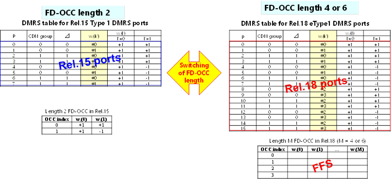
Agreement
For more than 4 layers SU-MIMO PUSCH, support
� Both Rel.15 Type 1/Type 2 DMRS ports and Rel.18 eType 1/eType 2 DMRS ports.
o For UE supporting Rel.18 eType 1/eType 2 DMRS ports, UE can be indicated with either of Rel.15 Type 1/Type 2 DMRS ports or Rel.18 eType 1/eType 2 DMRS ports.
� RRC based indication is supported as the baseline. FFS whether DCI based indication is further needed.
o For UE not supporting Rel.18 eType 1/eType 2 DMRS ports, UE can be indicated with Rel.15 Type 1/Type 2 DMRS ports only.
Agreement
For enhanced FD-OCC length for DMRS of PDSCH/PUSCH for Rel.18 eType 1 DMRS, support
� Opt.1-2: Length 4 FD-OCC is applied to 4 REs of DMRS within a PRB or across consecutive PRBs within an CDM group
Decision: As per email decision posted on Oct 12th,
Agreement
Confirm the working assumption in RAN1#110 with the following update:
� To increase the number of DMRS ports for PDSCH/PUSCH, support at least Opt.1 (introduce larger FD-OCC length than Rel.15 (e.g. 4 or 6)).
o FFS: FD-OCC length for Rel.18 DMRS type 1 and type
2.
o FFS: Whether it is needed to handle potential performance issues of Opt 1. For example, study if there is performance loss in case of large delay spread scenario. If needed, how (e.g. additionally support other options).
Agreement
For FD-OCC length 4 for DMRS of PDSCH/PUSCH for Rel.18 eType 1/eType 2 DMRS, support one from the following FD-OCCs (to be selected in RAN1#111):
� Opt.1-1: Walsh matrix (Hadamard code):
|
FD-OCC index |
wf(0) |
wf(1) |
wf(2) |
wf(3) |
|
0 |
+1 |
+1 |
+1 |
+1 |
|
1 |
+1 |
-1 |
+1 |
-1 |
|
2 |
+1 |
+1 |
-1 |
-1 |
|
3 |
+1 |
-1 |
-1 |
+1 |
� Opt.1-2: Cyclic shift with {0, π, π/2, 3π/2}:
|
FD-OCC index |
wf(0) |
wf(1) |
wf(2) |
wf(3) |
|
0 |
+1 |
+1 |
+1 |
+1 |
|
1 |
+1 |
-1 |
+1 |
-1 |
|
2 |
+1 |
+j |
-1 |
-j |
|
3 |
+1 |
-j |
-1 |
+j |
Agreement
For Rel.18 eType 1/eType 2 DMRS ports of PDSCH/PUSCH with FD-OCC length 4, association between DMRS port indexes, CDM group index, FD-OCC index, and TD-OCC index (across consecutive DMRS symbols, if any) are determined by the following Table 1 and Table 2.
� The p in Table 1 and Table 2 corresponds to DMRS port index for PUSCH.
� DMRS port index for PDSCH is determined by p +1000 in Table 1 and Table 2.
Table 1. Rel.18 eType 1 DMRS ports for PUSCH
|
p |
CDM group index |
FD-OCC index |
TD-OCC index |
|
0 |
0 |
0 |
0 |
|
1 |
0 |
1 |
0 |
|
2 |
1 |
0 |
0 |
|
3 |
1 |
1 |
0 |
|
4 |
0 |
0 |
1 |
|
5 |
0 |
1 |
1 |
|
6 |
1 |
0 |
1 |
|
7 |
1 |
1 |
1 |
|
8 |
0 |
2 |
0 |
|
9 |
0 |
3 |
0 |
|
10 |
1 |
2 |
0 |
|
11 |
1 |
3 |
0 |
|
12 |
0 |
2 |
1 |
|
13 |
0 |
3 |
1 |
|
14 |
1 |
2 |
1 |
|
15 |
1 |
3 |
1 |
Table 2. Rel.18 eType 2 DMRS ports for PUSCH
|
p |
CDM group index |
FD-OCC index |
TD-OCC index |
|
0 |
0 |
0 |
0 |
|
1 |
0 |
1 |
0 |
|
2 |
1 |
0 |
0 |
|
3 |
1 |
1 |
0 |
|
4 |
2 |
0 |
0 |
|
5 |
2 |
1 |
0 |
|
6 |
0 |
0 |
1 |
|
7 |
0 |
1 |
1 |
|
8 |
1 |
0 |
1 |
|
9 |
1 |
1 |
1 |
|
10 |
2 |
0 |
1 |
|
11 |
2 |
1 |
1 |
|
12 |
0 |
2 |
0 |
|
13 |
0 |
3 |
0 |
|
14 |
1 |
2 |
0 |
|
15 |
1 |
3 |
0 |
|
16 |
2 |
2 |
0 |
|
17 |
2 |
3 |
0 |
|
18 |
0 |
2 |
1 |
|
19 |
0 |
3 |
1 |
|
20 |
1 |
2 |
1 |
|
21 |
1 |
3 |
1 |
|
22 |
2 |
2 |
1 |
|
23 |
2 |
3 |
1 |
R1-2210264�������� FL summary on DMRS#2 Moderator (NTT DOCOMO)
R1-2210407������� FL summary on DMRS#3������������� Moderator (NTT DOCOMO)
From Oct 18th GTW session
Agreement
For FD-OCC length 4 in Rel.18 eType 1 DMRS for PDSCH, support the following:
Decision: As per email decision posted on Oct 19th,
Conclusion
For FD-OCC length 4 in Rel.18 eType 1 DMRS for PUSCH,
� No spec. enhancement is needed to handle orphan RE issue (e.g. if the total number of REs of DMRS in a CDM group is not multiples of 4, how to handle the remainder of REs), because gNB (receiver) can decide whether the scheduling restriction is needed or not.
Final summary in R1-2210408.
R1-2208376�������� SRS enhancements for TDD CJT and 8TX operation FUTUREWEI
R1-2208443�������� SRS enhancement for TDD CJT and UL 8Tx operation in Rel-18���������� Huawei, HiSilicon
R1-2208497�������� Discussion on SRS Enhancements� InterDigital, Inc.
R1-2208506�������� SRS enhancement targeting TDD CJT and 8 TX operation������ ZTE
R1-2208543�������� Discussion on SRS enhancement targeting TDD CJT and 8 TX operation�������������� Spreadtrum Communications
R1-2208630�������� Discussion on SRS enhancement��� vivo
R1-2208744�������� Discussion of SRS enhancement���� Lenovo
R1-2208796�������� SRS enhancement targeting TDD CJT and 8 TX operation������ OPPO
R1-2208874�������� On SRS Enhancement������ Google
R1-2208895�������� SRS enhancement targeting TDD CJT and 8 TX operation������ LG Electronics
R1-2208949�������� Discussion on SRS enhancement��� CATT
R1-2209043�������� Discussion on SRS enhancement in Rel-18�� Intel Corporation
R1-2209091�������� Considerations on SRS enhancement targeting TDD CJT and 8 TX operation�������������� Sony
R1-2209142�������� Discussion on SRS enhancement��� NEC
R1-2209260�������� Discussion on SRS enhancements�� xiaomi
R1-2209324�������� Discussion on SRS enhancement targeting TDD CJT and 8 TX operation�������������� CMCC
R1-2209383�������� SRS enhancement targeting TDD CJT and 8 TX operation������ Sharp
R1-2209434�������� Views on enhanced SRS configuration for 8TX and TDD CJT KDDI Corporation
R1-2209572�������� Views on Rel-18 MIMO SRS enhancement� Apple
R1-2209623�������� On SRS enhancements targeting TDD CJT and 8 TX operation������������� Ericsson
R1-2209718�������� Views on SRS enhancements��������� Samsung
R1-2209892�������� Discussion on SRS enhancement��� NTT DOCOMO, INC.
R1-2209971�������� SRS enhancement for TDD CJT and 8 Tx operation�� Qualcomm Incorporated
R1-2210065�������� SRS enhancement for TDD CJT and 8Tx operation��� Nokia, Nokia Shanghai Bell
R1-2210106�������� Discussion on SRS Enhancements for 8Tx Operation CEWiT
[110bis-e-R18-MIMO-05] � Jialing (Futurewei)
Email discussion on SRS enhancement by October 19
- Check points: October 14, October 19
R1-2210382������� FL Summary #1 on SRS enhancements���� Moderator (FUTUREWEI)
From Oct 11th GTW session
Agreement
Support at least one of the following for SRS interference randomization
R1-2210383������� FL Summary #2 on SRS enhancements���� Moderator (FUTUREWEI)
From Oct 14th GTW session
Agreement
For comb offset hopping for SRS and for randomized code-domain resource mapping for SRS transmission via cyclic shift hopping / randomization, further study the following:
� The hopping pattern (e.g., the pseudo-random sequence, time-domain granularity for hopping)
� The time-domain parameter and/or behavior (e.g., slot index, symbol index, re-initialization behavior)
� Network-configured ID for UE-specific initialization
� How the comb offset / cyclic shift value is determined by the parameters for each SRS port of a SRS resource for a SRS transmission occasion
� Potential issue on multiplexing with legacy UEs if CS hopping and/or comb offset hopping are enabled
� Applicability to periodic/semi-persistent/aperiodic SRS
Other details are not excluded
Agreement
For SRS TD OCC for SRS enhancements for TDD CJT, study:
� Comparison against SRS on 1 OFDM symbol
� Comparison against SRS repeated on multiple OFDM symbols
� Study the following aspects: evaluation performance, SRS overhead, per-symbol per-port transmission power, impact of channel delay, dropping rules of collision with other uplink resource, etc.
Conclusion
The discussion of resource mapping for SRS transmission based on network-provided parameters or system parameters is merged into the discussions of other SRS enhancements for TDD CJT.
R1-2210384������� FL Summary #3 on SRS enhancements���� Moderator (FUTUREWEI)
From Oct 18th GTW session
Agreement
For per-TRP power control and/or power control of one or multiple SRS transmission occasions towards to multiple TRPs, study the options for an SRS resource set:
� Option 1:
o Same power control process for all SRS resources of an SRS resource set where the power control process is based on one Po value and one closed loop state and jointly on more than one DL pathloss RS and/or more than one alpha
o Each transmission occasion of the SRS resource is towards multiple TRPs
� Option 2:
o More than 1 power control processes each for a subset of SRS resource of an SRS resource set where each of the power control process is based on a different UL power control parameter set (Po, alpha, and closed loop state) associated with a different DL pathloss RS
o Different transmission occasions of the SRS resource can be towards different TRPs
Agreement
For an 8-port SRS resource in a SRS resource set �antennaSwitching� (i.e., for 8T8R antenna switching), when the SRS resource is configured with m OFDM symbols (m >= 1), at least support the 8 ports mapped onto each of the m OFDM symbols using legacy schemes (repetition, frequency hopping, partial sounding, or a combination thereof).
� m takes the legacy values, i.e., 1,2,4,8,10,12,14.
Agreement
For one single SRS resource in a SRS resource set with usage �codebook� for 8Tx PUSCH, when the SRS resource is configured with n ports (n <= 8) and m OFDM symbols (m >= 1), at least support the n ports mapped onto each of the m OFDM symbols using legacy schemes (repetition, frequency hopping, partial sounding, or a combination thereof).
� n can be 8
� m takes the legacy values, i.e., 1,2,4,8,10,12,14.
Conclusion
� No further discussion of increasing the maximum number of cyclic shifts for CJT SRS.
� No further discussion of partial frequency sounding extensions for CJT SRS.
Final summary in R1-2210711.
R1-2209092�������� Considerations on UL precoding indication for multi-panel transmission�������������� Sony
R1-2208444�������� Discussion on UL precoding indication for multi-panel transmission���� Huawei, HiSilicon
R1-2208498�������� Further Discussion for Uplink Multi-panel Transmission��������� InterDigital, Inc.
R1-2208507�������� Enhancements on UL precoding indication for multi-panel transmission������������� ZTE
R1-2208544�������� Discussion on UL precoding indication for multi-panel transmission���� Spreadtrum Communications
R1-2208631�������� Discussion on UL precoding indication for multi-panel transmission���� vivo
R1-2208678�������� UL precoding indication for multi-panel transmission Ericsson
R1-2208745�������� UL precoding indication for multi-panel transmission Lenovo
R1-2208797�������� Transmission scheme and UL precoding indication for multi-panel transmission�������������� OPPO
R1-2208875�������� On Simultaneous Multi-Panel Transmission Google
R1-2208896�������� UL precoding indication for multi-panel transmission LG Electronics
R1-2208950�������� UL precoding indication for multi-panel transmission CATT
R1-2209009�������� Discussion on UL precoding indication for multi-panel transmission���� Fujitsu
R1-2209044�������� UL precoding indication for multi-panel transmission Intel Corporation
R1-2209143�������� Discussion on UL precoding indication for multi-panel transmission���� NEC
R1-2209261�������� Enhancements on multi-panel uplink transmission����� xiaomi
R1-2209325�������� Discussion on UL precoding indication for multi-panel transmission���� CMCC
R1-2209384�������� Views on UL multi-panel transmission�������� Sharp
R1-2209496�������� Simultaneous transmission across multiple UE panels MediaTek Inc.
R1-2209549�������� On UL precoding indication for simultaneous multi-panel transmission Fraunhofer IIS, Fraunhofer HHI
R1-2209573�������� Views on UL precoding indication for multi-panel simultaneous transmissions�������������� Apple
R1-2209719�������� Views on UL precoding indication for STxMP����������� Samsung
R1-2209893�������� Discussion on multi-panel transmission������� NTT DOCOMO, INC.
R1-2209972�������� Simultaneous multi-panel transmission�������� Qualcomm Incorporated
R1-2210026�������� UL precoding for multi-panel transmission�� PANASONIC
R1-2210066�������� Precoder Indication for Multi-Panel UL Transmission Nokia, Nokia Shanghai Bell
[110bis-e-R18-MIMO-06] � Li (OPPO)
Email discussion on UL precoding indication for multi-panel TX by October 19
- Check points: October 14, October 19
R1-2210305������� Summary #1 on Rel-18 STxMP��� Moderator (OPPO)
From Oct 11th GTW session
Agreement
� Reuse the DCI field �Antenna Ports� in DCI format 0_1 and 0_2 to indicate DMRS ports for SDM scheme of single-DCI based STxMP PUSCH:
o The total numbers of layers, L, indicated by two TPMI fields of CB PUSCH or two SRI fields of NCB PUSCH is used to determine the DMRS port indication table.
o L1 of the indicated DMRS ports are associated with the L1 PUSCH layers which are indicated by the first TPMI field for CB PUSCH or the first SRI field for NCB PUSCH and the rest L- L1 of the indicated DMRS ports are associated with the L-L1 PUSCH layers which are indicated by the second TPMI field for CB PUSCH or the second SRI field for the NCB PUSCH.
� FFS: how to partition the indicated DMRS ports among the PUSCH layers.
� Down-select one from the following two Alts for SDM scheme in RAN1#111:
o Alt1: the DMRS ports associated with two TPMI/SRI fields must be in different CDM groups.
o Alt2: the DMRS ports associated with two TPMI/SRI fields can be in same or different CDM groups.
Agreement
Support STxMP PUSCH+PUSCH transmission in multi-DCI based system in Rel-18.
� Two independent PUSCHs associated with different TRPs can be transmitted by a UE simultaneously in same active BWP.
� The total number of layers of these two PUSCHs is up to 4.
� FFS: whether the number of layers of each of these two PUSCHs is up to 2.
Decision: As per email decision posted on Oct 13th,
Agreement
For SDM scheme of single-DCI based STxMP PUSCH
R1-2210306������� Summary #2 on Rel-18 STxMP��� Moderator (OPPO)
From Oct 14th GTW session
Agreement
Regarding the TPMI/SRI indication for multi-DCI based STxMP PUSCH+PUSCH:
� Configure two SRS resource sets for CB or NCB.
o FFS: Whether/how to associate coresetPoolIndex with SRS resource set implicitly or explicitly.
o FFS: the maximal number of configured/indicated SRS resources in each set for NCB/CB
o FFS: the maximal number of SRS ports in each set for CB.
� FFS: Separate codebooks and separate maxRanks are configured for different SRS resource sets.
� For type 1 CG-PUSCH (if supported), FFS how to associate the PUSCH with one TRP
o e.g., configure a coresetPoolIndex value in a type 1 CG-PUSCH
o e.g., use a single CG to configure two type 1 CG PUSCHs for STxMP PUSCH+PUSCH
Agreement
Support dynamic switching between SDM scheme of single-DCI based STxMP PUSCH and sTRP transmission
FFS the indication of dynamic switching
FFS: max number of layers when switching to sTRP transmission
Agreement
Support SFN-based transmission scheme for STxMP PUSCH transmission in single-DCI based mTRP system in Rel-18.
Decision: As per email decision posted on Oct 14th,
Agreement
Support to configure up to 2 PTRS ports for SDM scheme of single-DCI based STxMP PUSCH transmission:
�
For 2 PTRS ports, Ports 0 and 1 are
associated with one DMRS port of two different panels respectively
Study how to use the �PTRS-DMRS association� field in DCI format 0_1 and 0_2 to
indicate the PTRS-DMRS association for SDM scheme.
R1-2210307������� Summary #3 on Rel-18 STxMP��� Moderator (OPPO)
From Oct 18th GTW session
Agreement
For the switching between SDM scheme of single-DCI based STxMP PUSCH and Rel-17 mTRP PUSCH TDM scheme, Alt2 is supported. FFS whether Alt1 is supported in addition to Alt2.
Agreement
The multi-DCI based STxMP PUSCH+PUSCH transmission supports fully/partially/non-overlapping in frequency domain and fully/partially overlapping in time domain.
Agreement
Multi-DCI based STxMP PUSCH+PUSCH transmission at least supports the following PUSCH combinations:
� DG-PUSCH + DG-PUSCH
� CG-PUSCH + DG-PUSCH
To support up to 4 or more layers per UE in UL targeting CPE/FWA/vehicle/industrial devices.
R1-2208445�������� Discussion on SRI/TPMI enhancement for enabling 8 TX UL transmission�������������� Huawei, HiSilicon
R1-2208499�������� Enhanced SRI/TPMI for 8TX UE��� InterDigital, Inc.
R1-2208508�������� SRI/TPMI enhancement for enabling 8 TX UL transmission��� ZTE
R1-2208545�������� Discussion on SRI/TPMI enhancement for enabling 8 TX UL transmission�������������� Spreadtrum Communications
R1-2208632�������� Discussion on enabling 8 TX UL transmission����������� vivo
R1-2208746�������� SRI/TPMI enhancement for enabling 8TX UL transmission���� Lenovo
R1-2208798�������� SRI TPMI enhancement for 8 TX UL transmission��� OPPO
R1-2208876�������� On SRI/TPMI Indication for 8Tx Transmission��������� Google
R1-2208897�������� SRI/TPMI enhancement for enabling 8 TX UL transmission��� LG Electronics
R1-2208951�������� Codebook and SRI/TPMI enhancement for UL 8 TX� CATT
R1-2209045�������� Discussion on enhancement for 8Tx UL transmission Intel Corporation
R1-2209093�������� Discussion on enhancement for 8Tx UL transmission Sony
R1-2209144�������� Discussion on SRI/TPMI enhancement�������� NEC
R1-2209262�������� Enhancements on 8Tx uplink transmission�� xiaomi
R1-2209326�������� Discussion on SRI/TPMI enhancement for enabling 8 TX UL transmission�������������� CMCC
R1-2209385�������� Views on 8 TX UL transmission���� Sharp
R1-2209497�������� SRI/TPMI enhancement for enabling 8 Tx UL transmission���� MediaTek Inc.
R1-2209574�������� Views on SRI/TPMI enhancement for enabling 8 TX UL transmission� Apple
R1-2209671�������� SRI/TPMI Enhancement for Enabling 8 TX UL Transmission Ericsson
R1-2209720�������� Views on TPMI/SRI enhancements for 8Tx UL transmission�� Samsung
R1-2209894�������� Discussion on 8 TX UL transmission����������� NTT DOCOMO, INC.
R1-2209973�������� Enhancements for 8 Tx UL transmissions���� Qualcomm Incorporated
R1-2210067�������� UL enhancements for enabling 8Tx UL transmission Nokia, Nokia Shanghai Bell
[110bis-e-R18-MIMO-07] � Afshin (InterDigital)
Email discussion on SRI/TPMI enhancement for enabling 8 TX UL by October 19
- Check points: October 14, October 19
R1-2210376������� FL Summary on SRI/TPMI Enhancements; First Round��� Moderator (InterDigital)
From Oct 11th GTW session
Agreement
Support the following cases for codebook design for 8TX precoders
� Full coherent precoders with Ng=1
o FFS: Full coherent precoders with Ng=2, Ng=4
� Partial coherent precoders with Ng=2 and Ng=4
o This does not imply any relation with the number of TPMI indications for 8TX precoder
� Non-coherent precoders
Decision: As per email decision posted on Oct 13th,
Agreement
For codebook design of an 8TX partial-coherent UE, configured with an 8-port SRS resource
Agreement
For SRI and/or transmitter precoder matrix indication for codebook-based uplink transmission by an 8TX UE, study
Agreement
In Rel-18, on support of full power operation by a partial/non-coherent 8TX UE configured with codebook-based transmission:
� Identify and agree on at least one potential PA architecture by RAN1#111.
R1-2210377������� FL Summary on SRI/TPMI Enhancements; Second Round Moderator (InterDigital)
From Oct 14th GTW session
Agreement
For 8TX UE codebook-based uplink transmission,
Decision: As per email decision posted on Oct 15th,
Agreement
For SRS configuration required for non-codebook-based UL transmission by an 8TX UE, Alt1 is supported, that is
Decision: As per email decision posted on Oct 18th,
Agreement
For SRS configuration supporting codebook -based UL transmission for an 8TX UE ,
R1-2210378������� FL Summary on SRI/TPMI Enhancements; Third Round� Moderator (InterDigital)
From Oct 18th GTW session
Working Assumption
For uplink transmission with rank>4, support dual CW transmission.
Agreement
If dual CW is supported for uplink transmission with Rank>4 by an 8TX UE, reuse DL Rel-15 codeword to layer mapping for both codebook-based and non-codebook-based transmission.
For information:
R1-2210379�������� Recommended Direction on SRI/TPMI Enhancements for RAN1#111� Moderator (InterDigital)
Please refer to RP-213598 for detailed scope of the WI.
[111-R18-MIMO] � Eko (Samsung)
To be used for sharing updates on online/offline schedule, details on what is to be discussed in online/offline sessions, tdoc number of the moderator summary for online session, etc
Including extension for indication of multiple DL/UL TCI states, simultaneous multi-panel UL transmission, and power control for UL single DCI.
R1-2210845�������� Unified TCI framework extension for multi-TRP������� FUTUREWEI
R1-2210911�������� Discussion on unified TCI framework extension for multi-TRP������������� Huawei, HiSilicon
R1-2210925�������� Further Discussion on Unified TCI Extension for MTRP��������� InterDigital, Inc.
R1-2210935�������� Enhancements on unified TCI framework extension for multi-TRP������� ZTE
R1-2210990�������� Discussion on unified TCI framework extension for multi-TRP������������� vivo
R1-2211051�������� Unified TCI framework extension for multi-TRP������� Ericsson
R1-2211070�������� Views on unified TCI extension for MTRP�� Fujitsu
R1-2211114�������� Discussion on unified TCI framework extension for M-TRP operation� Hyundai Motor Company
R1-2211167�������� Discussion on unified TCI framework extension for multi-TRP operation�������������� CATT
R1-2211217�������� Unified TCI framework extension for multi-TRP������� PANASONIC
R1-2211219�������� Discussion on unified TCI framework extension for multi-TRP������������� Spreadtrum Communications
R1-2211290�������� Discussion of unified TCI framework for multi-TRP� Lenovo
R1-2211334�������� Unified TCI framework extension for multi-TRP������� xiaomi
R1-2211382�������� Unified TCI Framework for Multi-TRP������� Intel Corporation
R1-2211425�������� Unified TCI framework extension for multi-TRP������� OPPO
R1-2211512�������� Discussion on unified TCI framework extension for multi-TRP������������� Transsion Holdings
R1-2211588�������� Multi-TRP enhancements for the unified TCI framework�������� Fraunhofer IIS, Fraunhofer HHI
R1-2211664�������� Discussion on unified TCI framework extension for multi-TRP������������� CMCC
R1-2211797�������� Extension of unified TCI framework for multi-TRP�� Apple
R1-2211859�������� Unified TCI framework extension for multi-TRP/panel����������� LG Electronics
R1-2211880�������� Discussion on unified TCI framework extension for multi-TRP������������� FGI
R1-2211886�������� Unified TCI framework extension for multi-TRP������� Sharp
R1-2211969�������� Discussion on unified TCI framework extension for multi-TRP������������� NTT DOCOMO, INC.
R1-2212026�������� Views on unified TCI extension focusing on m-TRP� Samsung
R1-2212099�������� Extension of unified TCI framework for mTRP���������� Qualcomm Incorporated
R1-2212167�������� Unified TCI framework extension for multi-TRP������� Nokia, Nokia Shanghai Bell
R1-2212211�������� Discussion on unified TCI framework extension for multi-TRP������������� Google
R1-2212236�������� Unified TCI framework extension for multi-TRP������� MediaTek Inc.
R1-2212333�������� Discussion on unified TCI framework extension for multi-TRP������������� ITRI
R1-2212352�������� Discussion on unified TCI framework extension for multi-TRP������������� NEC
R1-2212376�������� Discussion on unified TCI framework extension for multi-TRP operation����������� TCL Communication Ltd.
R1-2212420�������� Discussion on Unified TCI framework extension for multi-TRP������������ CEWiT
R1-2212522������� Moderator summary on extension of unified TCI framework (Round 0)�������������� Moderator (MediaTek Inc.)
From Nov 14th session
Agreement
On unified TCI framework extension for S-DCI based MTRP, a DCI field in DCI format 1_1/1_2 that schedules/activates PDSCH reception is used to determine which one or both of the indicated joint/DL TCI states shall be applied to the scheduled/activated PDSCH reception
� The presence of the DCI field is configurable by RRC; when the DCI field is not present in DCI format 1_1/1_2, the UE shall apply the default indicated joint/DL TCI state(s) to PDSCH reception
� FFS: The DCI field is a new indicator field or an existing field (e.g., the existing TCI field)
FFS: How to apply the indicated joint/DL TCI state(s) to PDSCH reception scheduled/activated by DCI format 1_0.
Above applies for the case where PDSCHs scheduled by the same DCI.
Agreement
On unified TCI framework extension for S-DCI based MTRP, use RRC configuration to inform that the UE shall apply the first one, the second one, or both of the indicated joint/UL TCI states to a PUCCH resource/group
� Note: Detail of the RRC configuration is left to RAN2 design
Agreement
On unified TCI framework extension for S-DCI based MTRP, in one beam indication instance, the existing TCI field in DCI format 1_1/1_2 (with or without DL assignment) can indicate joint/DL/UL TCI state(s) for one or both of the two TRPs in a CC/BWP or a set of CCs/BWPs in a CC list
� FFS: Increase on the size of the TCI field
� Note: The term TRP is used only for discussion purpose in RAN1 and whether/how to capture this is FFS
Agreement
On unified TCI framework extension, PDSCH-CJT is supported as a S-DCI based MTRP scheme
Note: Above does not preclude discussions specific to PDSCH-CJT design in the unified TCI framework
R1-2212759������� Moderator summary on extension of unified TCI framework (Round 1)�������������� Moderator (MediaTek Inc.)
From Nov 16th session
Agreement
On unified TCI framework extension, down-select at least one of the following alternatives for PDSCH-CJT applying both indicated joint TCI states (if the UE supports two indicated joint/DL states for PDSCH-CJT):
� Alt1: PDSCH DMRS port(s) is QCLed with the DL RSs of both indicated joint TCI states with respect to QCL-TypeA
� Alt2: PDSCH DMRS port(s) is QCLed with the DL RSs of both indicated joint TCI states with respect to QCL-TypeA except for QCL parameters {Doppler shift, Doppler spread} of the second indicated joint TCI state
� Alt3: PDSCH DMRS port(s) is QCLed with the DL RS of the first indicated joint TCI state with respect to QCL-TypeA and QCLed with the DL RS of the second indicated joint TCI state with respect to QCL-TypeB
Agreement (modified as shown in Nov17th session)
On unified TCI framework extension for S-DCI based MTRP, use Use an indicator
field (could be reusing an existing DCI field or introducing a new DCI field)
in the DCI format 0_1/0_2 to inform which joint/UL TCI state(s) indicated by
MAC-CE/DCI the UE shall apply to PUSCH transmission scheduled/activated by the
DCI format 0_1/0_2.
Agreement
On unified TCI framework extension for M-DCI based MTRP, the same configuration/rule used in Rel-17 unified TCI framework (for determining whether the UE shall apply the indicated joint/DL TCI state to PDCCH on a CORESET and respective PDSCH) is reused to determine whether the UE shall apply the indicated joint/DL TCI state specific to a coresetPoolIndex value to PDCCH on a CORESET associated with the same coresetPoolIndex value and PDSCH scheduled/activated by the PDCCH.
R1-2212878������� Moderator summary on extension of unified TCI framework (Round 2)�������������� Moderator (MediaTek Inc.)
From Nov 17th session
Agreement
On unified TCI framework extension for M-DCI based MTRP, the UE shall apply the indicated joint/UL TCI state specific to a coresetPoolIndex value to PUSCH transmission scheduled/activated by PDCCH (including DG-PUSCH and Type2 CG-PUSCH) on a CORESET that is associated with the same coresetPoolIndex value.
Agreement
On unified TCI framework extension for S-DCI based MTRP, a new indicator field is supported as the DCI field in DCI format 1_1/1_2 that schedules/activates PDSCH reception to determine which one or both of the indicated joint/DL TCI states shall be applied to the scheduled/activated PDSCH reception
� FFS: Detail design of the new indicator field
R1-2210846�������� Enhancements to support two TAs for multi-DCI������ FUTUREWEI
R1-2210912�������� Study on TA enhancement for UL M-TRP transmssion������������ Huawei, HiSilicon
R1-2210926�������� Enhanced Operation of mTRP with Multiple TA�������� InterDigital, Inc.
R1-2210936�������� TA enhancement for multi-DCI������ ZTE
R1-2210991�������� Discussion on two TAs for multi-DCI-based multi-TRP operation�������� vivo
R1-2211052�������� Two TAs for multi-DCI��� Ericsson
R1-2211168�������� Discussion on Two TAs for UL multi-TRP operation CATT
R1-2211220�������� Discussion on two TAs for multi-DCI based multi-TRP����������� Spreadtrum Communications
R1-2211291�������� Discussion of two TAs for multi-DCI UL transmission������������ Lenovo
R1-2211335�������� Discussion on two TAs for multi-TRP operation�������� xiaomi
R1-2211383�������� On two TAs for multi-DCI Intel Corporation
R1-2211426�������� Two TAs for multi-DCI��� OPPO
R1-2211513�������� Discussion on two TAs for multi-DCI based multi-TRP operation��������� Transsion Holdings
R1-2211576�������� Discussion on two TAs for multi-DCI based on multi-TRP operation���� TCL Communication Ltd.
R1-2211665�������� Discussion on two TAs for multi-DCI���������� CMCC
R1-2211798�������� Two TAs for multi-DCI based Uplink Transmissions Apple
R1-2211860�������� Two TAs for multi-TRP/panel�������� LG Electronics
R1-2211970�������� Discussion on two TAs for multi-DCI���������� NTT DOCOMO, INC.
R1-2212027�������� Views on two TAs for m-DCI��������� Samsung
R1-2212100�������� Supporting two TAs for multi-DCI based mTRP�������� Qualcomm Incorporated
R1-2212168�������� Two TAs for UL multi-DCI multi-TRP operation������ Nokia, Nokia Shanghai Bell
R1-2212187�������� Two TAs for multi-DCI��� Sharp
R1-2212212�������� Discussion on two TAs for multi-DCI���������� Google
R1-2212237�������� UL Tx Timing Management for MTRP Operation����� MediaTek Inc.
R1-2212353�������� Discussion on two TAs for multi-DCI���������� NEC
R1-2212589������� Moderator Summary #1 on Two TAs for multi-DCI����������� Moderator (Ericsson)
From Nov 14th session
Working Assumption
For multi-DCI based inter-cell Multi-TRP operation with two TA enhancement, one additional PRACH configuration is supported for each configured additional PCI
� the additional PRACH configuration is used in a RACH procedure triggered by a PDCCH order for the corresponding configured additional PCI
Agreement
For multi-DCI based Multi-TRP operation with two TA enhancement, support CFRA triggered by PDCCH order for both intra-cell and inter-cell cases.
R1-2212775������� Moderator Summary #2 on Two TAs for multi-DCI����������� Moderator (Ericsson)
From Nov 16th session
Agreement
For multi-DCI based Multi-TRP operation with two TA enhancement, support the case where a PDCCH order sent by one TRP triggers RACH procedure towards either the same TRP or a different TRP at least for inter-cell Multi-DCI.
� FFS: for intra-cell Multi-DCI
� FFS: whether there are any restrictions needed
� FFS: if cross TRP RACH triggering is an optional feature
R1-2212862������� Moderator Summary #3 on Two TAs for multi-DCI����������� Moderator (Ericsson)
From Nov 17th session
Conclusion
For multi-DCI based Multi-TRP operation with two TA enhancement, there is no consensus to support enhancements for CBRA triggered by PDCCH order.
Conclusion
For multi-DCI based Multi-TRP operation with two TA enhancement, it is up to RAN2 to decide whether there is a need to enhance CBRA procedure to support per TRP UE-initiated RACH procedure.
R1-2212957������� [Draft] LS on Multi-DCI Multi-TRP with two TAs Ericsson
Decision: As per decision on Nov 18th, the draft LS is endorsed. Final LS is approved in R1-2213004.
Including CSI enhancement for high/medium UE velocities and coherent JT (CJT).
R1-2210913�������� CSI enhancement for coherent JT and mobility���������� Huawei, HiSilicon
R1-2210927�������� Discussion on CSI Enhancements for CJT and Medium/High UE Velocities�������������� InterDigital, Inc.
R1-2210937�������� CSI enhancement for high/medium UE velocities and CJT������ ZTE
R1-2210992�������� Discussion on CSI enhancement for high-medium UE velocities and coherent JT vivo
R1-2211118�������� On CSI Enhancement������� Google
R1-2211169�������� CSI enhancement for high/medium UE velocities and coherent JT�������� CATT
R1-2211221�������� Discussion on CSI enhancement for high/medium UE velocities and coherent JT�������������� Spreadtrum Communications
R1-2211292�������� Discussion of CSI enhancement for high speed UE and coherent JT������ Lenovo
R1-2211336�������� Views on CSI enhancement for high/medium UE velocities and CJT���� xiaomi
R1-2211384�������� On CSI enhancements������ Intel Corporation
R1-2211427�������� CSI enhancement for high/medium UE velocities and coherent JT�������� OPPO
R1-2211587�������� CSI enhancements for medium UE velocities and coherent JT Fraunhofer IIS, Fraunhofer HHI
R1-2211603�������� Further considerations on CSI enhancement for high/medium UE velocities and CJT�������������� Sony
R1-2211666�������� Discussion on CSI enhancement for high/medium UE velocities and� CJT�������������� CMCC
R1-2211799�������� Views on Rel-18 MIMO CSI enhancement�� Apple
R1-2211861�������� Potential CSI enhancement for high/medium UE velocities and coherent JT�������� LG Electronics
R1-2211887�������� CSI enhancement Sharp
R1-2211939�������� Views on CSI Enhancements for CJT����������� AT&T
R1-2211971�������� Discussion on CSI enhancement���� NTT DOCOMO, INC.
R1-2212029�������� Summary of OFFLINE discussion on Rel-18 MIMO CSI��������� Moderator (Samsung)
R1-2212030�������� Views on CSI enhancements���������� Samsung
R1-2212101�������� CSI enhancements for medium UE velocities and Coherent-JT Qualcomm Incorporated
R1-2212169�������� CSI enhancement for high/medium UE velocities and CJT������ Nokia, Nokia Shanghai Bell
R1-2212697�������� On CSI enhancements for Rel-18 NR MIMO evolution����������� Ericsson (rev of R1-2212174)
R1-2212232�������� CSI Enhancements������������ MediaTek Inc.
R1-2212276�������� Discussion on CSI enhancement���� Mavenir
R1-2212348�������� Discussion on CSI enhancement���� NEC
R1-2212028������� Moderator summary on Rel-18 CSI enhancements Moderator (Samsung)
From Nov 14th session
Agreement
For the Type-II codebook refinement for CJT mTRP, the values of the following codebook parameters are gNB-configured via higher-layer (RRC) signaling and common across all N CSI-RS resources:
Conclusion
On the Type-II codebook refinement for CJT mTRP, for mode-1 and mode-2, there is no consensus on introducing additional/explicit per-CSI-RS-resource amplitude scaling and/or co-phase (with separate alphabet set(s)) as additional PMI component(s).
� Note: This conclusion has no impact on the Working Assumption reached in RAN1#110bis-e regarding W2 quantization group
Agreement
On the Type-II codebook refinement for CJT mTRP, regarding the codebook parameter R, the supported value(s) from the legacy specification are reused.
� FFS: whether additional value 4 can also be added
Agreement
On the Type-II codebook refinement for CJT mTRP, regarding the codebook parameter b, introduce as a candidate value b = 1/8 in addition to the supported value(s) from the legacy specification.
� FFS (by RAN1#111): whether additional value 1 can also be added
Agreement
On the Type-II codebook refinement for CJT mTRP, regarding the codebook parameter pv, in addition to the supported value(s) from the legacy specification for Rel-16 regular eType-II codebook, introduce as a candidate value
FFS (by RAN1#111): whether additional value pv = 1/2 for v=1,2,3,4 can also be added
Agreement
On the Type-II codebook refinement for CJT mTRP:
� The maximum value of 2NN1N2 is 128
o The support of 2NN1N2 >32 is UE optional for UEs supporting Rel-18 CJT CSI enhancement
� Note: Following the legacy specification on the maximum number of NZP CSI-RS ports per CSI-RS resource, the maximum value of 2N1N2 is 32.
Agreement
On the Type-II codebook refinement for CJT mTRP, on the L parameter, down select from the following alternatives (by RAN1#111):
FFS (by RAN1#111):
Agreement
On the Type-II codebook refinement for CJT mTRP, for mode-1, study and down select (no later than RAN1#112) only one from the following schemes:
For all the above alternatives, the legacy FD basis selection indication scheme is applied on each selected FD basis.
Note: Per previous agreements, the number of selected FS basis vectors (Mv/pv or M) is gNB-configured via higher-layer signaling and common across the N CSI-RS resources
Conclusion
For the Rel-18 Type-II codebook refinement for high/medium velocities, there is no consensus on applying DD unit for CQI. Therefore, DD unit (of size d slots) is applied only to PMI.
� Note: This conclusion has no impact on the number of CQIs included in one CSI reporting instance (a separate issue to be decided separately)
Agreement
For the Rel-18 Type-II codebook refinement for high/medium velocities,
� For PMI, DD unit duration of d (in slots) is the duration associated with each of the N4 W2 matrices (combining coefficients before DD compression at the UE, or after DD de-compression at the gNB).
� TBD (by RAN1#111): The time instance and/or PMI(s) in which a CQI is associated with, given the CSI reporting window WCSI (in slots), and the number of CQI(s) X included in a CSI report.
Agreement
For the Type-II codebook refinement for high/medium velocities, for N4>1, regarding the parameter Q, at least Q=2 is supported.
� FFS: Whether Q=3 and/or Q=4 are also supported as other candidate value(s), as well as the supported Parameter Combination(s)
Agreement
For the Type-II codebook refinement for high/medium velocities, the parameter WCSI (in slots) is determined as follows: WCSI = dN4
Agreement
For the Type-II codebook refinement for high/medium velocities, the parameter N4 (length of DFT vector, unit-less) is gNB-configured via higher-layer (RRC) signalling at least from the following set of candidate values: {1, 2, 4}
� FFS: If additional candidate value(s) of N4 are supported, e.g. 3, 5, 6, 8, 10, 16, 32, as well as the supported Parameter Combination(s)
Agreement
For the Type-II codebook refinement for high/medium velocities, the parameter K (the number of AP-CSI-RS resources for the CMR) is gNB-configured via higher-layer (RRC) signalling at least from the following set of candidate values: {4, 8}
� FFS: If additional candidate value(s) of K are supported, e.g. 5, 12, 16, also taking into account other use cases (e.g. for training filter coefficients, prediction or performance monitoring) and TDD
Agreement
For the Type-II codebook refinement for high/medium velocities, the parameter m (offset between two AP-CSI-RS resources for the CMR, in slots) is gNB-configured via higher-layer (RRC) signalling from the following set of candidate values: {1, 2}
� FFS: Whether 4, 5, 8, 12, and/or 16 are also supported as other candidate value(s)
Agreement
For the Type-II codebook refinement for high/medium velocities, regarding the bitmap(s) for indicating the locations of the NZCs, support the following:
FFS: Further overhead reduction on bitmap(s)
FFS: Whether the number of NZCs is upper bounded across all DD basis vectors or per DD basis vector
Agreement
For the Rel-18 Type-II codebook refinement for high/medium velocities,
� The definition and supported values for each of the SD/FD codebook parameters follow the legacy specification.
o FFS: The supported parameter combinations considering SD, FD, and DD codebook parameters
� For N4=1, the legacy quantization is fully reused.
Agreement
For the Rel-18 Type-II codebook
refinement for high/medium velocities, for N4=1, one CSI reporting instance includes a single ![]() �per layer, a single
�per layer, a single ![]() , and a single
, and a single ![]() .
.
Conclusion
For the Rel-18 Type-II codebook refinement for high/medium velocities, when N4>1, there is no consensus in introducing rotation factor (selected for each SD basis vector) as an additional PMI component.
Agreement
For the Type-II codebook refinement for high/medium velocities, in one CSI reporting instance, for a given CQI sub-band, at least support including one CQI
� FFS: The association of the CQI with PMI(s) and/or slot(s) within one duration of CSI reporting window WCSI
� FFS: The support for including more than one CQIs
Agreement
For the Type-II codebook refinement for high/medium velocities, the parameter δ (in slots) is gNB-configured via higher-layer (RRC) signalling from a set of the following candidate values:
R1-2212721�������� Moderator Summary on Rel-18 CSI enhancements: Tuesday offline session�������������� Moderator (Samsung)
R1-2212706������� Moderator Summary#2 on Rel-18 CSI enhancements: Round 1������� Moderator (Samsung)
From Nov 16th session
Conclusion:
On the Type-II codebook refinement for CJT mTRP, regarding the codebook parameter , there is no consensus in supporting the additional value of 1.
Agreement
On the Type-II codebook refinement for CJT mTRP, regarding the codebook parameter pv, support the additional value of pv=1/2 for v=1,2,3,4 with the following condition:
� Only to be used in combination with other parameter value(s) to limit the increase in PMI overhead comparable to the maximum overhead of the legacy Rel-16/17 Type-II codebooks (exact parameter combination(s) FFS).
Agreement
On
the Type-II codebook refinement for CJT mTRP, regarding the bitmap(s) for
indicating the locations of NZCs, reuse the legacy design. This implies that
the size of the bitmap for selected CSI-RS resource n (Bn)
is, ![]() �
�
Agreement
On the W2 coefficient quantization scheme for the Type-II codebook refinement for CJT mTRP, for N=3 and N=4, just as N=2, reuse the following components of the legacy Rel-16/17 per-coefficient quantization scheme:
� Alphabets for amplitude and phase
� Quantization of phase and quantization of differential amplitude relative to a reference, reference amplitude (with SCI determining the location of one reference amplitude), where the reference is defined for each layer and each �group� of coefficients
Agreement
For the Rel-18 Type-II codebook refinement for high/medium velocities, regarding the time instance and/or PMI(s) in which a CQI is associated with, given the CSI reporting window WCSI (in slots), assuming 1 CQI in one sub-band and one CSI reporting instance, down-select (by RAN1#112) one from the following alternatives:
Note: The N4 W2 matrices represent the combining coefficients before DD compression at the UE, or after DD de-compression at the gNB.
Agreement
For the Rel-18 Type-II codebook refinement for high/medium velocities, decide by RAN1#112 whether including X>1 CQIs in one sub-band and one CSI reporting instance are supported.
Agreement
For the Type-II codebook refinement for high/medium velocities, for N4>1, regarding parameter Q, decide in RAN1#112 whether to support the additional values of 3 and/or 4.
Agreement
For the Type-II codebook refinement for high/medium velocities, regarding the parameter δ (in slots), support the additional value of 2.
� FFS (by RAN1#112): For the last supported additional value, down select between 1, 3, 4, and 5.
Agreement
For the Type-II codebook refinement for high/medium velocities, regarding the parameter N4 (length of DFT vector, unit-less), support 8 as an additional candidate value.
� The candidate values supported by UE are reported via UE capability (details can be discussed in UE feature).
Conclusion:
For the Type-II codebook refinement for high/medium velocities, regarding the parameter m (offset between two AP-CSI-RS resources for the CMR, there is no consensus in supporting additional candidate value(s).
Agreement
On the Type-II codebook refinement for CJT mTRP, regarding the SD basis selection, for a configured value of NTRP, a set of NL combinations of values for {L1, ..., LNTRP} is gNB-configured via higher-layer (RRC) signaling
FFS: Whether the set of NL combinations of values for {L1, ..., LNTRP} can be implicitly derived
Following the legacy design, for all the selected N CSI-RS resources, the SD basis oversampling group for each CSI-RS resource is indicated in CSI part 2 using an indicator selected from a set of O1O2 codepoints.
From Nov 17th session
Agreement
For the Type-II codebook refinement for high/medium velocities, regarding the parameter d (in slots),
If more than one candidate values of d are supported, the value of d is gNB-configured via higher-layer (RRC) signalling
R1-2212819������� Moderator Summary#3 on Rel-18 CSI enhancements: Round 2������� Moderator (Samsung)
Agreement
For the Rel-18 TRS-based TDCP reporting, down select only one of the following alternatives by RAN1#112:
Down-selection is to done based on, at least, the (single-)user throughput (LLS) performance comparison among the alternatives assuming:
� Three special cases of an agreed use case (companies can select only one or more): aiding gNB to determine switching between Type-I and Rel-16 eType-II codebooks, or to determine SRS periodicity in the UL-SRS reciprocity-based precoding scheme; or aiding the gNB implementation in CSI prediction for TDD
o In their simulations on switching between Type-I and Rel-16 eType-II codebooks, companies should state how to calculate the metric for the determination and how to set the threshold, and what the UE reports.
o In their simulations on UL-SRS reciprocity-based precoding scheme, companies should state how to set the SRS periodicity based on the reported metrics, and what the UE reports; and the results should be displayed in terms of user throughput vs SRS overhead
o In their simulations on CSI prediction for TDD, the results should be the correlation between real channel and predicted channel, and what the UE reports; aided by the reported metric.
o Other scenarios of the agreed use cases can optionally be simulated
� Based on the agreed EVM for sTRP and mTRP
Note: Different alternatives may or may not apply to different use cases
FFS: The need for a measure of confidence level in the TDCP report, and/or UE behaviour when the quality of TDCP measurement is not sufficiently high
FFS: TDCP parameter(s) signalled with respect to each alternative
R1-2212870�������� Moderator Summary on Rel-18 CSI enhancements: Thursday offline session�������������� Moderator (Samsung)
Including increasing orthogonal DMRS ports for UL/DL MU-MIMO and 8 Tx UL SU-MIMO.
R1-2210847�������� On increasing the number of orthogonal DM-RS ports for MU-MIMO�������������� FUTUREWEI
R1-2210914�������� Enhancements on DMRS in Rel-18 Huawei, HiSilicon
R1-2210928�������� Discussion on DMRS Enhancements������������ InterDigital, Inc.
R1-2210934�������� Discussions on increased number of orthogonal DMRS ports�� New H3C Technologies Co., Ltd.
R1-2210938�������� DMRS enhancement for UL/DL MU-MIMO and 8 Tx UL SU-MIMO�� ZTE
R1-2210993�������� Discussion on DMRS enhancements������������ vivo
R1-2211119�������� On DMRS Enhancement�� Google
R1-2211170�������� On DMRS enhancements in Rel-18 CATT
R1-2211222�������� Discussion on increased number of orthogonal DMRS ports��� Spreadtrum Communications
R1-2211293�������� Discussion of increased number of orthogonal� DMRS ports��� Lenovo
R1-2211337�������� Discussion on DMRS enhancement xiaomi
R1-2211385�������� DMRS Enhancements for Rel-18 NR����������� Intel Corporation
R1-2211428�������� DMRS enhancement for Rel-18 MIMO�������� OPPO
R1-2211586�������� On increased number of orthogonal DMRS ports������� Fraunhofer IIS, Fraunhofer HHI
R1-2211667�������� Discussion on increased number of orthogonal DMRS ports��� CMCC
R1-2211771�������� On increased number of orthogonal DMRS ports for MU-MIMO and 8 Tx UL SU-MIMO�� Ericsson
R1-2211800�������� Views on supporting increased number of orthogonal DMRS ports������� Apple
R1-2211862�������� Increased number of orthogonal DMRS ports������������� LG Electronics
R1-2211888�������� Increased number of orthogonal DMRS ports������������� Sharp
R1-2211972�������� Discussion on DMRS enhancements������������ NTT DOCOMO, INC.
R1-2212031�������� Views on DMRS enhancements����� Samsung
R1-2212102�������� Design for increased number of orthogonal DMRS ports��������� Qualcomm Incorporated
R1-2212170�������� Rel-18 UL and DL DMRS Enhancements���� Nokia, Nokia Shanghai Bell
R1-2212233�������� Increased number of orthogonal DMRS ports������������� MediaTek Inc.
R1-2212349�������� Discussion on increased number of orthogonal DMRS ports��� NEC
R1-2212523������� FL summary#1 on DMRS������������� Moderator (NTT DOCOMO)
From Nov 14th session
Agreement
For FD-OCC length 4 for PDSCH/PUSCH, select the following:
� Opt.1-1 (Walsh matrix) for PDSCH
� Opt.1-2 (Cyclic shift) for PUSCH
R1-2212524������� FL summary#2 on DMRS������������� Moderator (NTT DOCOMO)
From Nov 14th session
Agreement
Agreement
R1-2212760������� FL summary#3 on DMRS������������� Moderator (NTT DOCOMO)
From Nov 17th session
Agreement
For length 2 TD-OCC (across consecutive DMRS symbols, if any) for DMRS of PDSCH/PUSCH for Rel.18 eType 1/2 DMRS, support Opt.1:
� Opt.1:
|
TD-OCC index |
Wt(0) |
Wt(1) |
|
0 |
+1 |
+1 |
|
1 |
+1 |
-1 |
Agreement
Table 7.3.1.1.2-25B: PTRS-DMRS association for UL PTRS port 0
|
Value |
DMRS port |
|
0 |
1st scheduled DMRS port with the CW with the higher MCS |
|
1 |
2nd scheduled DMRS port the CW with the higher MCS |
|
2 |
3rd scheduled DMRS port the CW with the higher MCS |
|
3 |
4th scheduled DMRS port the CW with the higher MCS |
o Alt.2: The size of PTRS-DMRS association field is 3bit in DCI format 0_1/0_2, and the following PTRS-DMRS association for UL PTRS port 0 is specified in TS38.212.
Table 7.3.1.1.2-25B: PTRS-DMRS association for UL PTRS port 0
|
Value |
DMRS port |
|
0 |
1st scheduled DMRS port |
|
1 |
2nd scheduled DMRS port |
|
2 |
3rd scheduled DMRS port |
|
3 |
4th scheduled DMRS port |
|
4 |
5th scheduled DMRS port |
|
5 |
6th scheduled DMRS port |
|
6 |
7th scheduled DMRS port |
|
7 |
8th scheduled DMRS port |
Agreement
Table 7.3.1.2.2-1-X: Antenna port(s) (1000 + DMRS port), dmrs-Type=eType1, maxLength=1
|
One Codeword: Codeword 0 enabled, Codeword 1 disabled |
Two Codewords: Codeword 0 enabled, Codeword 1 enabled |
||||||
|
Value |
Number of DMRS CDM group(s) without data |
DMRS port(s) |
Notes |
Value |
Number of DMRS CDM group(s) without data |
DMRS port(s) |
Notes |
|
0 |
[1] |
[0] |
Cat. 1 |
[0] |
[2] |
[0,1,2,3,8] |
[Rank 5-8 with one DMRS symbol] |
|
1 |
[1] |
[1] |
[1] |
[2] |
[0,1,2,3,8,10] |
||
|
2 |
[1] |
[0,1] |
[2] |
[2] |
[0,1,2,3,8,9,10] |
||
|
3 |
2 |
0 |
[3] |
[2] |
[0,1,2,3,8,9,10,11] |
||
|
4 |
2 |
1 |
|
|
|
|
|
|
5 |
2 |
2 |
|
|
|
|
|
|
6 |
2 |
3 |
|
|
|
|
|
|
7 |
2 |
0,1 |
|
|
|
|
|
|
8 |
2 |
2,3 |
|
|
|
|
|
|
9 |
[2] |
[0-2] |
|
|
|
|
|
|
10 |
[2] |
[0-3] |
|
|
|
|
|
|
11 |
[2] |
[0,2] |
|
|
|
|
|
|
12 |
[1] |
[8] |
Cat.2 |
|
|
|
|
|
13 |
[1] |
[9] |
|
|
|
|
|
|
14 |
[1] |
[8,9] |
|
|
|
|
|
|
15 |
2 |
8 |
|
|
|
|
|
|
16 |
2 |
9 |
|
|
|
|
|
|
17 |
2 |
10 |
|
|
|
|
|
|
18 |
2 |
11 |
|
|
|
|
|
|
19 |
2 |
8,9 |
|
|
|
|
|
|
20 |
2 |
10,11 |
|
|
|
|
|
|
21 |
[2] |
[8-10] |
|
|
|
|
|
|
22 |
[2] |
[8-11] |
|
|
|
|
|
|
23 |
[2] |
[8, 10], [9, 11] |
|
|
|
|
|
|
24 |
[1] |
[0,1,8] |
Cat.3 |
|
|
|
|
|
25 |
[1] |
[0,1,8,9] |
|
|
|
|
|
|
26 |
2 |
0,1,8 |
|
|
|
|
|
|
27 |
2 |
0,1,8,9 |
|
|
|
|
|
|
28 |
2 |
2,3,10 |
|
|
|
|
|
|
29 |
2 |
2,3,10,11 |
|
|
|
|
|
|
|
|
|
|
|
|
|
|
|
|
|
|
|
|
|
|
|
R1-2210848�������� SRS enhancements for TDD CJT and 8TX operation FUTUREWEI
R1-2210915�������� SRS enhancement for TDD CJT and UL 8Tx operation in Rel-18���������� Huawei, HiSilicon
R1-2210929�������� Enhanced SRS for CJT and 8TX UEs����������� InterDigital, Inc.
R1-2210939�������� SRS enhancement targeting TDD CJT and 8 TX operation������ ZTE
R1-2210994�������� Discussion on SRS enhancement��� vivo
R1-2211120�������� On SRS Enhancement������ Google
R1-2211171�������� On SRS enhancement� in Rel-18���� CATT
R1-2211223�������� Discussion on SRS enhancement targeting TDD CJT and 8 TX operation�������������� Spreadtrum Communications
R1-2211272�������� Views on SRS enhancement targeting TDD CJT and 8 TX operation���� KDDI Corporation
R1-2211294�������� Discussion of SRS enhancement���� Lenovo
R1-2211338�������� Discussion on SRS enhancements�� xiaomi
R1-2211386�������� Discussion on SRS enhancement in Rel-18�� Intel Corporation
R1-2211429�������� SRS enhancement targeting TDD CJT and 8 TX operation������ OPPO
R1-2211554�������� Discussion on SRS enhancement targeting TDD CJT� ETRI
R1-2211604�������� Considerations on precoded SRS���� Sony
R1-2211668�������� Discussion on SRS enhancement targeting TDD CJT and 8 TX operation�������������� CMCC
R1-2211801�������� Views on Rel-18 MIMO SRS enhancement� Apple
R1-2211863�������� SRS enhancement targeting TDD CJT and 8 TX operation������ LG Electronics
R1-2211889�������� SRS enhancement targeting TDD CJT and 8 TX operation������ Sharp
R1-2211973�������� Discussion on SRS enhancement��� NTT DOCOMO, INC.
R1-2212032�������� Views on SRS enhancements��������� Samsung
R1-2212103�������� SRS enhancement for TDD CJT and 8 Tx operation�� Qualcomm Incorporated
R1-2212171�������� SRS enhancement for TDD CJT and 8Tx operation��� Nokia, Nokia Shanghai Bell
R1-2212350�������� Discussion on SRS enhancement��� NEC
R1-2212377�������� On SRS enhancements targeting TDD CJT and 8 TX operation������������� Ericsson
R1-2212694������� FL Summary #1 on SRS enhancements���� Moderator (FUTUREWEI)
From Nov 14th session
Agreement
For SRS comb offset hopping and/or cyclic shift hopping, for each SRS port,
� FFS: Hopping pattern
� Support at least hopping based on slot index, OFDM symbol index
o FFS: Use of symbol group based on repetition factor
o FFS: Additional details on intra-slot hopping based on OFDM symbol index, inter-slot hopping based on slot index, per occasion of SRS resource
o FFS: Re-initialization periodicity
� Applicable to at least periodic/semi-persistent SRS with usage antennaSwitching
o FFS: Other types of SRS
� FFS: Configuring a subset of comb offsets / cyclic shifts for comb offset hopping / cyclic shift hopping, respectively
� FFS: Combined comb offset hopping and cyclic shift hopping, supporting both, or down selecting one
R1-2212695������� FL Summary #3 on SRS enhancements���� Moderator (FUTUREWEI)
From Nov 16th session
Agreement
For an 8-port SRS resource in a SRS resource set with usage �codebook� or �antennaSwitching�, when the 8 ports are mapped onto one or more OFDM symbols using legacy schemes (repetition, frequency hopping, partial sounding, or a combination thereof), at least support:
� For comb 2, support 1 and 2 comb offsets
� For comb 4, support 2 and [4] comb offset
� For comb 8, support 4 comb offsets
Agreement
For single SRS resource in a SRS resource set with usage �codebook� for 8Tx PUSCH or �antennaSwitching� (i.e., for 8T8R antenna switching), when the SRS resource is configured with 8 ports and m OFDM symbols (m > 1), support the case of 8 ports mapped onto the m OFDM symbols
� Option 1: Different SRS ports are mapped onto different OFDM symbols (i.e., TDM)
� FFS: m can be legacy values, i.e., 2,4,[8,10,12,14].
R1-2212696������� FL Summary #4 on SRS enhancements���� Moderator (FUTUREWEI)
From Nov 17th session
Agreement:
For SRS comb offset hopping and/or cyclic shift hopping, for each SRS port, the hopping pattern is determined based on:
� Option 1: The hopping pattern is based on the pseudo-random sequence c(i), initialized with a network-configured ID.
o
FFS: The ID could be cell ID ![]() , SRS
sequence identity
, SRS
sequence identity ![]() , C-RNTI,
or a new ID
, C-RNTI,
or a new ID
o FFS: The relation between the legacy group / sequence hopping and the new hopping
Agreement
For SRS interference randomization, support one from the following options� (to be decided in RAN1#112):
� Opt. 1: Cyclic shift hopping
� Opt. 2: Comb offset hopping
� Opt. 3: Both cyclic shift hopping and comb offset hopping
o FFS: details including whether to support separate and/or combined hopping
o FFS: details on UE capability and signaling
Conclusion
No consensus on enhanced signaling for flexible SRS transmission in Rel-18.
Final summary in R1-2212941.
R1-2210916�������� Discussion on UL precoding indication for multi-panel transmission���� Huawei, HiSilicon
R1-2210930�������� Uplink Precoding Indication and Multi-panel Transmission���� InterDigital, Inc.
R1-2210940�������� Enhancements on UL precoding indication for multi-panel transmission������������� ZTE
R1-2210995�������� Discussion on UL precoding indication for multi-panel transmission���� vivo
R1-2211071�������� Discussion on UL precoding indication for multi-panel transmission���� Fujitsu
R1-2211121�������� On Simultaneous Multi-Panel Transmission Google
R1-2211172�������� Enhancements on UL precoding indication for multi-panel transmission�������������� CATT
R1-2211218�������� UL Precoding for Multi-panel Transmission PANASONIC
R1-2211224�������� Discussion on UL precoding indication for multi-panel transmission���� Spreadtrum Communications
R1-2211295�������� UL precoding indication for multi-panel transmission Lenovo
R1-2211339�������� Enhancements on multi-panel uplink transmission����� xiaomi
R1-2211387�������� UL precoding indication for multi-panel transmission Intel Corporation
R1-2211430�������� Transmission scheme and UL precoding indicaton for multi-panel transmission�������������� OPPO
R1-2211591�������� On UL precoding indication for simultaneous multi-panel transmission Fraunhofer IIS, Fraunhofer HHI
R1-2211605�������� Considerations on 1 vs. 2 CWs for SDM multi-panel transmissions������� Sony
R1-2211669�������� Discussion on UL precoding indication for multi-panel transmission���� CMCC
R1-2211802�������� Views on UL precoding indication for multi-panel simultaneous PUSCH transmissions������ Apple
R1-2211864�������� UL precoding indication for multi-panel transmission LG Electronics
R1-2211890�������� Views on UL multi-panel transmission�������� Sharp
R1-2211974�������� Discussion on multi-panel transmission������� NTT DOCOMO, INC.
R1-2212033�������� Views on UL precoding indication for STxMP����������� Samsung
R1-2212104�������� Simultaneous multi-panel transmission�������� Qualcomm Incorporated
R1-2212172�������� Precoder Indication for Multi-Panel UL Transmission Nokia, Nokia Shanghai Bell
R1-2212238�������� Simultaneous transmission across multiple UE panels MediaTek Inc.
R1-2212354�������� Discussion on UL precoding indication for multi-panel transmission���� NEC
R1-2212375�������� UL precoding indication for multi-panel transmission Ericsson
R1-2212579������� Summary #1 on Rel-18 STxMP��� Moderator (OPPO)
From Nov 14th session
Agreement
For the DMRS port indication for SDM scheme single-DCI based STxMP transmission, support Alt2:
� Alt2: the DMRS ports associated with two TPMI/SRI fields can be in same or different CDM groups.
Agreement
Support CG PUSCH + CG PUSCH in multi-DCI based STxMP PUSCH+PUSCH transmission.
Agreement
Support the SFN scheme for single-DCI based STxMP PUCCH transmission.
Conclusion
There is no consensus on the support STxMP PUCCH+PUCCH in multi-DCI based mTRP system.
R1-2212580������� Summary #2 on Rel-18 STxMP��� Moderator (OPPO)
From Nov 16th session
Agreement
Agreement
R1-2212581������� Summary #3 on Rel-18 STxMP��� Moderator (OPPO)
From Nov 17th session
Agreement
For the SFN scheme of single-DCI based STxMP PUSCH:
� Configure two SRS resource sets for CB or NCB.
o FFS: Number of SRS resources of SRS resource set, and number of SRS ports of SRS resource
� The DCI indicates two SRI fields and TPMI fields for SFN transmission,
� On the indication of number of layers for CB and NCB PUSCH:
o Alt1: Similar to rel-17 mTRP TDM scheme, the number of layers is indicated by the first SRI field (for NCB PUSCH) or the first TPMI field (for CB PUSCH);
Agreement
For dynamic switching between SDM scheme of single-DCI based STxMP PUSCH and sTRP transmission:
Agreement
For SDM scheme single-DCI based STxMP transmission, when L1 and L2 layers are indicated/determined by two TPMI fields of CB PUSCH or two SRI fields of NCB PUSCH respectively:
Conclusion
There is no consensus to support layer combinations {1+3} and {3+1} in SDM scheme of single-DCI based STxMP PUSCH.
To support up to 4 or more layers per UE in UL targeting CPE/FWA/vehicle/industrial devices.
R1-2210917�������� Discussion on SRI/TPMI enhancement for enabling 8 TX UL transmission�������������� Huawei, HiSilicon
R1-2210931�������� Discussion on SRI/TPMI Enhancement for 8TX UE�� InterDigital, Inc.
R1-2210941�������� SRI/TPMI enhancement for enabling 8 TX UL transmission��� ZTE
R1-2210996�������� Discussion on enabling 8 TX UL transmission����������� vivo
R1-2211122�������� On SRI/TPMI Indication for 8Tx Transmission��������� Google
R1-2211173�������� Discussion on codebook and SRI/TPMI enhancement for UL 8 TX������� CATT
R1-2211225�������� Discussion on SRI/TPMI enhancement for enabling 8 TX UL transmission�������������� Spreadtrum Communications
R1-2212659�������� SRI/TPMI enhancement for enabling 8TX UL transmission���� Lenovo� (rev of R1-2211296)
R1-2211340�������� Enhancements on 8Tx uplink transmission�� xiaomi
R1-2211388�������� Discussion on enhancement for 8Tx UL transmission Intel Corporation
R1-2211431�������� SRI TPMI enhancement for 8 TX UL transmission��� OPPO
R1-2211670�������� Discussion on SRI/TPMI enhancement for enabling 8 TX UL transmission�������������� CMCC
R1-2211803�������� Views on SRI/TPMI enhancement for enabling 8 TX UL transmission� Apple
R1-2211865�������� SRI/TPMI enhancement for enabling 8 TX UL transmission��� LG Electronics
R1-2211891�������� Views on 8 TX UL transmission���� Sharp
R1-2211894�������� SRI/TPMI Enhancement for Enabling 8 TX UL Transmission Ericsson
R1-2211975�������� Discussion on 8 TX UL transmission����������� NTT DOCOMO, INC.
R1-2212034�������� Views on TPMI/SRI enhancements for 8Tx UL transmission�� Samsung
R1-2212105�������� Enhancements for 8 Tx UL transmissions���� Qualcomm Incorporated
R1-2212173�������� UL enhancements for enabling 8Tx UL transmission Nokia, Nokia Shanghai Bell
R1-2212234�������� SRI/TPMI enhancement for enabling 8 Tx UL transmission���� MediaTek Inc.
R1-2212351�������� Discussion on SRI/TPMI enhancement�������� NEC
R1-2212422�������� SRI/TPMI enhancement for enabling 8 TX UL transmission��� CEWiT
R1-2212556�������� FL Summary on SRI/TPMI Enhancements; Preparatory���������� Moderator (InterDigital)
R1-2212557������� FL Summary on SRI/TPMI Enhancements; First Round��� Moderator (InterDigital)
Agreement:
For a fully-coherent uplink precoding by an 8TX UE,
� Support NR Rel-15 single panel DL Type I codebook as the starting point for design of the codebook
o
FFS:
For a constructed codebook with size M based on above method, unless ![]() ; otherwise, round up
the codebook size to the smallest integer
; otherwise, round up
the codebook size to the smallest integer ![]() �by adding
�by adding ![]() �precoders generated via
Alt 2a.
�precoders generated via
Alt 2a.
� No LS to RAN4 will be needed
R1-2212558������� FL Summary on SRI/TPMI Enhancements; Second Round Moderator (InterDigital)
From Nov 16th session
Agreement:
For PUSCH transmission with rank>4 by an 8TX UE, to support dual CW transmission,
FFS: Optimization of DCI to indicate the above
Note: Strive to reuse Rel-15 NR DL schemes where possible.
Agreement:
For PUSCH transmission with rank>4 by an 8TX UE, to support UCI multiplexing on PUSCH, down-select at least one of the following options in RAN1#112,
Agreement:
For CB-based 8TX PUSCH transmission, for rank indication, down-select among the following
R1-2212559������� FL Summary on SRI/TPMI Enhancements; Third Round� Moderator (InterDigital)
From Nov 17th session
Agreement:
Study full TX power uplink codebook-based transmission by a partially/non-coherent 8TX precoder,
� Reuse Rel-16 UE capability definitions for discussion purpose, i.e., UE Capability 1, 2 and 3
� For full TX power transmission by UE Capability 2/3, at least, following exemplary PA architectures can be considered
o Other cases of interest are not precluded, down-select preferred potential architecture for the purpose of 8TX full power study in RAN#112.
o This can be used for other UE Power Classes as well.
|
8TX UE, Power class 3 (23 dBm) Pi= Nominal power rating of each PA |
||
|
|
Regular UE |
P1=P2= �=P8=14 dBm (Full power supported by Mode1) |
|
Full-power capable UE |
Full power capability with any PA comb. (CAP1) Example: P1=P2= �=P8= 23 dBm
|
|
|
Full power capability with 1 PA (CAP3) Example: P1=P2= �=P7= 14 dBm P8= 23 dBm
|
||
|
(lower priority) Full power capability with 2 PAs (CAP2) Example 2a: P1=P2= �=P6= 14 dBm, P7=P8 ≥ 20 dBm Example 2b: P1=P2= �= P8= 20 dBm
|
||
|
(lower priority) Full power capability with 4 PAs (CAP2) Example 3a: P1=P2= �=P4= 14 dBm, P5=P6= �=P8 ≥ 17 dBm Example 3b: P1=P2= �= P8 = 17 dBm
|
||
|
(lower priority) Full power capability with 6 PAs (CAP2) Example 4a: P1=P2= 14 dBm, P3=P4= �=P8 ≥ 15.3 dBm Example 4b: P1=P2= � = P8≥ 15.3 dBm
|
||
|
|
||
|
|
||
|
|
||
Agreement:
For an 8TX partial/non-coherent precoder, for study on full power codebook-based PUSCH transmissions, use Rel-16 full power modes as the starting point for the design.
Note: This does not mandate support of all Rel-16 modes.
R1-2212560�������� Recommended Direction on SRI/TPMI Enhancements for RAN1#112� Moderator (InterDigital)
Please refer to RP-223276 for detailed scope of the WI.
[112-R18-MIMO] � Eko (Samsung)
To be used for sharing updates on online/offline schedule, details on what is to be discussed in online/offline sessions, tdoc number of the moderator summary for online session, etc
Including extension for indication of multiple DL/UL TCI states, simultaneous multi-panel UL transmission, and power control for UL single DCI.
R1-2300048�������� Unified TCI framework extension for multi-TRP������� FUTUREWEI
R1-2300093�������� Discussion on unified TCI framework extension for multi-TRP������������� Huawei, HiSilicon
R1-2300156�������� Details on Unified TCI Extension for MTRP InterDigital, Inc.
R1-2300181�������� Enhancements on unified TCI framework extension for multi-TRP������� ZTE
R1-2300203�������� Discussion on unified TCI framework extension for multi-TRP������������� Spreadtrum Communications
R1-2300248�������� Unified TCI framework extension for multi-TRP������� OPPO
R1-2300327�������� Unified TCI framework extension for multi-TRP������� Panasonic
R1-2300333�������� Unified TCI framework extension for multi-TRP������� Ericsson
R1-2300436�������� Further discussion on unified TCI framework extension for multi-TRP� vivo
R1-2300487�������� Discussion on unified TCI framework extension for multi-TRP������������� FGI
R1-2300503�������� Multi-TRP enhancements for the unified TCI framework�������� Fraunhofer IIS, Fraunhofer HHI
R1-2300510�������� Discussion of unified TCI framework for multi-TRP� Lenovo
R1-2300522�������� Unified TCI framework extension for multi-TRP/panel����������� LG Electronics
R1-2300545�������� Unified TCI framework extension for multi-TRP������� xiaomi
R1-2300600�������� Discussion on unified TCI framework extension for multi-TRP operation����������� TCL Communication Ltd.
R1-2300650�������� Further discussions on unified TCI framework extension for multi-TRP operation�������������� CATT
R1-2300740�������� Discussion on unified TCI framework extension for MTRP����� Fujitsu
R1-2300820�������� Discussion on unified TCI framework extension for multi-TRP������������� NEC
R1-2300847�������� Unified TCI framework extension for multi-TRP������� Sharp
R1-2300865�������� Discussion on unified TCI framework extension for multi-TRP������������� Sony
R1-2300899�������� Discussion on unified TCI framework extension for multi-TRP������������� Hyundai Motor Company
R1-2300932�������� Unified TCI Framework for Multi-TRP������� Intel Corporation
R1-2300982�������� Discussion on unified TCI framework extension for multi-TRP������������� CMCC
R1-2301165�������� Discussion on unified TCI framework extension for multi-TRP������������� Google
R1-2301245�������� Views on unified TCI extension focusing on m-TRP� Samsung
R1-2301318�������� Discussion on unified TCI framework extension for multi-TRP������������� ITRI
R1-2301329�������� Unified TCI framework Extension for mTRP������������� Apple
R1-2301395�������� Extension of unified TCI framework for mTRP���������� Qualcomm Incorporated
R1-2301461�������� Discussion on sDCI mTRP PDSCH regarding eUTCI framework���������� ASUSTeK
R1-2301477�������� Discussion on unified TCI framework extension for multi-TRP������������� NTT DOCOMO, INC.
R1-2301580�������� Unified TCI framework extension for multi-TRP������� MediaTek Inc.
R1-2301642�������� Unified TCI framework extension for multi-TRP������� Nokia, Nokia Shanghai Bell
R1-2301686�������� Discussion on Unified TCI framework extension for multi-TRP������������ CEWiT
R1-2301773������� Moderator summary on extension of unified TCI framework (Round 0)�������������� Moderator (MediaTek Inc.)
Presented in Monday session
R1-2302000������� Moderator summary on extension of unified TCI framework (Round 1)�������������� Moderator (MediaTek Inc.)
From Wednesday session
Agreement
On unified TCI framework extension for S-DCI based MTRP, a 2-bit [TCI selection field] can be configured by RRC to be present in a DCI format 1_1/1_2 that schedules/activates PDSCH reception (including dynamic PDSCH and SPS PDSCH) according to the followings:
� If the DCI format 1_1/1_2 indicates codepoint "00" for the [TCI selection field], the UE shall apply the first one of two indicated joint/DL TCI states to all PDSCH DMRS port(s) of corresponding PDSCH transmission occasions(s) scheduled/activated by the DCI format 1_1/1_2
� If the DCI format 1_1/1_2 indicates codepoint "01" for the [TCI selection field], the UE shall apply the second one of two indicated joint/DL TCI states to all PDSCH DMRS port(s) of corresponding PDSCH transmission occasions(s) scheduled/activated by the DCI format 1_1/1_2
� If the DCI format 1_1/1_2 indicates codepoint "10" for the [TCI selection field], the UE shall apply both indicated joint/DL TCI states to the PDSCH reception scheduled/activated by the DCI format 1_1/1_2
� FFS: Whether and how to use the codepoint "11" of the [TCI selection field]
If the UE is in FR1, or the UE supports the capability of two default beams for S-DCI based MTRP in FR2 regardless of threshold, above apply to PDSCH reception(s) scheduled/activated by the DCI format 1_1/1_2.
If the UE doesn�t support the capability of two default beams for S-DCI based MTRP in FR2, above apply to the scheduled/activated PDSCH reception when the offset between the reception of the scheduling DCI format 1_1/1_2 and the scheduled/activated PDSCH reception is equal to or larger than a threshold
FFS: Detail of the capability of two default beams for S-DCI based MTRP
FFS: The threshold value
Agreement
On unified TCI framework extension for S-DCI based MTRP, when two SRS resource sets for CB/NCB are configured, support the followings for PUSCH transmission scheduled/activated by a DCI format 0_1/0_2 (including DG and Type2 CG):
� If the DCI format 0_1/0_2 indicates codepoint "00" for the existing SRS resource set indicator, the UE shall apply the first indicated joint/UL TCI state to all PUSCH antenna port(s) of corresponding PUSCH transmission occasions(s)
� If the DCI format 0_1/0_2 indicates codepoint "01" for the existing SRS resource set indicator, the UE shall apply the second indicated joint/UL TCI state to all PUSCH antenna port(s) of corresponding PUSCH transmission occasions(s)
� If the DCI format 0_1/0_2 indicates codepoint "10" or �11� for the existing SRS resource set indicator:
FFS: The case that the spatial Tx filter(s) determined from the indicated joint/UL TCI state(s) applied to a PUSCH transmission is different from the spatial Tx filter(s) used for the SRS transmission corresponding to the SRS resource(s) indicated to the PUSCH transmission
Agreement
On unified TCI framework extension, if an indicated joint/UL TCI state(s) applies to a PUSCH/PUCCH/SRS transmission occasion(s) or antenna port(s), the UE shall determine UL Tx power for the PUSCH/PUCCH/SRS transmission occasion(s) or antenna port(s) based on the UL PC parameter setting for PUSCH/PUCCH/SRS, if any, and the PL-RS included in the indicated joint/UL TCI state
� FFS: For STxMP, the maximum Tx power when the UE determines UL Tx power for the PUSCH/PUCCH transmission occasion(s) or antenna port(s) (discussed after receiving RAN4 reply on UE power limitation for STxMP in FR2)
� FFS: Default UL PC parameter setting(s) if one or both of indicated joint/UL TCI states applied to PUSCH/PUCCH/SRS transmission occasion(s) or antenna port(s) does/do not include the UL PC parameter setting(s) for PUCCH/PUSCH/SRS
R1-2302123������� Moderator summary on extension of unified TCI framework (Round 2)�������������� Moderator (MediaTek Inc.)
From Thursday session
Agreement
On unified TCI framework extension for M-DCI based MTRP, down-select from the following options for PUCCH transmission:
� Opt1: A coresetPoolIndex value can be provided per PUCCH resource/resource group, and the UE shall apply the indicated joint/UL TCI state specific to the coresetPoolIndex value to the corresponding PUCCH transmission
� Opt2: An RRC configuration can be provided per PUCCH resource/resource group to inform that the UE shall apply the first or the second indicated joint/UL TCI state to the corresponding PUCCH transmission, where the first and the second indicated joint/DL TCI states correspond to the indicated joint/UL TCI states specific to coresetPoolIndex value 0 and value 1, respectively.
� Opt3: For a PUCCH transmission triggered by PDCCH on a CORESET when the UCI in the PUCCH transmission carries HARQ-ACK information only, the UE shall apply the indicated joint/UL TCI state specific to a coresetPoolIndex value to the PUCCH transmission, where the coresetPoolIndex value is determined from the one associated with the CORESET. Otherwise, either Opt1 or Opt2 is adopted.
�
Opt4: For a PUCCH transmission with an LRR trigged for either the
first BFD-RS set (![]() ) or the second
BFD-RS set (
) or the second
BFD-RS set (![]() ) when the
UE is provided only one or two schedulingRequestID-BFR configuration, the UE shall apply
the indicated joint/UL TCI state specific to a coresetPoolIndex value to
the PUCCH transmission, where the coresetPoolIndex value is 1 when the
LRR is trigged for the first BFD-RS set (
) when the
UE is provided only one or two schedulingRequestID-BFR configuration, the UE shall apply
the indicated joint/UL TCI state specific to a coresetPoolIndex value to
the PUCCH transmission, where the coresetPoolIndex value is 1 when the
LRR is trigged for the first BFD-RS set (![]() ) and the coresetPoolIndex
value is 0 when the LRR is trigged for the second BFD-RS set (
) and the coresetPoolIndex
value is 0 when the LRR is trigged for the second BFD-RS set (![]() ). Otherwise,
either Opt1 or Opt2 is adopted.
). Otherwise,
either Opt1 or Opt2 is adopted.
Note: Either Opt1 or Opt2 must be supported
Agreement
On unified TCI framework extension for S-DCI based MTRP, down-select at least one of the followings for PDSCH reception scheduled/activated by DCI format 1_1/1_2 configured w/o the [TCI selection field]:
� Alt1: Using RRC configuration to inform that the UE shall apply the first one, the second one, or both of two indicated joint/DL TCI states to the scheduled/activated PDSCH reception
� Alt2: The UE shall apply the first one of two indicated joint/DL TCI state(s) to the scheduled/activated PDSCH reception
� Alt3: The UE shall apply both of two indicated joint/DL TCI states to the scheduled/activated PDSCH reception
� Alt3A: The UE shall apply the same joint/DL TCI state(s) that is applied to the PDCCH reception with the scheduling/activation DCI to the scheduled/activated PDSCH reception
� Alt4: Which indicated joint/DL TCI state(s) is/are applied to the scheduled/activated PDSCH reception is determined according to the existing TCI field of the most recently applied beam indication DCI
Above applies at least if the offset between the reception of the scheduling DCI format 1_1/1_2 and the scheduled/activated PDSCH reception is equal to or larger than a threshold (if the threshold is needed)
R1-2300049�������� Enhancements to support two TAs for multi-DCI������ FUTUREWEI
R1-2300094�������� Study on TA enhancement for UL M-TRP transmission���������� Huawei, HiSilicon
R1-2300157�������� Discussion on mTRP with Multiple TA�������� InterDigital, Inc.
R1-2300182�������� TA enhancement for multi-DCI������ ZTE
R1-2300204�������� Discussion on two TAs for multi-DCI based multi-TRP����������� Spreadtrum Communications
R1-2300249�������� Two TAs for multi-DCI based multi-TRP operation�� OPPO
R1-2300334�������� Two TAs for multi-DCI��� Ericsson
R1-2300359�������� Discussion on two TAs for multi-DCI based on multi-TRP operation���� TCL Communication Ltd.
R1-2300437�������� Further discussion on two TAs for multi-DCI-based multi-TRP operation����������� vivo
R1-2300489�������� Discussion on two TAs for multi-DCI���������� FGI
R1-2300511�������� Discussion of two TAs for multi-DCI UL transmission������������ Lenovo
R1-2300523�������� Two TAs for multi-TRP/panel�������� LG Electronics
R1-2300546�������� Discussion on two TAs for multi-TRP operation�������� xiaomi
R1-2300651�������� On Two TAs for UL multi-DCI multi-TRP operation CATT
R1-2300821�������� Discussion on two TAs for multi-DCI���������� NEC
R1-2300919�������� Two TAs for multi-DCI��� Sharp
R1-2300933�������� On two TAs for multi-DCI Intel Corporation
R1-2300983�������� Discussion on two TAs for multi-DCI���������� CMCC
R1-2301166�������� Discussion on two TAs for multi-DCI���������� Google
R1-2301246�������� Views on two TAs for m-DCI��������� Samsung
R1-2301330�������� Views on Two TAs for mDCI mTRP������������ Apple
R1-2301396�������� Supporting two TAs for multi-DCI based mTRP�������� Qualcomm Incorporated
R1-2301478�������� Discussion on two TAs for multi-DCI���������� NTT DOCOMO, INC.
R1-2301581�������� UL Tx Timing Management for MTRP Operation����� MediaTek Inc.
R1-2301643�������� Two TAs for UL multi-DCI multi-TRP operation������ Nokia, Nokia Shanghai Bell
R1-2301904������� Moderator Summary #1 on Two TAs for multi-DCI����������� Moderator (Ericsson)
From Monday session
Conclusion
For inter-cell multi-DCI based multi-TRP operation with two TA enhancement, there is no consensus to introduce additional type 1 CSS configuration per additional PCI.
R1-2302044������� Moderator Summary #2 on Two TAs for multi-DCI����������� Moderator (Ericsson)
From Wednesday session
Agreement
For associating TAGs to target UL channels/signals for multi-DCI based multi-TRP operation, support the following:
Associate TAG to TCI-state
FFS:
on how to handle association when Rel-15/16 spatial relation framework is used
for FR1
R1-2302111������� Moderator Summary #3 on Two TAs for multi-DCI����������� Moderator (Ericsson)
From Thursday session
Agreement
Confirm the following working assumption:
For multi-DCI based inter-cell Multi-TRP operation with two TA enhancement, one additional PRACH configuration is supported for each configured additional PCI
� the additional PRACH configuration is used in a RACH procedure triggered by a PDCCH order for the corresponding configured additional PCI
Agreement
For multi-DCI based Multi-TRP operation with two TA enhancement, for the case when the UE does not support UL STxMP transmission, down-select at least one of the following in RAN1#112bis-e:
TBD: how to capture the down-selected alternative(s) in the specifications in case specification impact is deemed needed.
Including CSI enhancement for high/medium UE velocities and coherent JT (CJT).
R1-2300095�������� CSI enhancement for coherent JT and mobility���������� Huawei, HiSilicon
R1-2300158�������� Enhanced CSI for CJT and Medium/High UE Velocities��������� InterDigital, Inc.
R1-2300183�������� CSI enhancement for high/medium UE velocities and CJT������ ZTE
R1-2300205�������� Discussion on CSI enhancement for high/medium UE velocities and coherent JT�������������� Spreadtrum Communications
R1-2300250�������� CSI enhancement for high/medium UE velocities and coherent JT�������� OPPO
R1-2301771�������� On CSI Enhancement������� Google� (rev of R1-2300391)
R1-2300438�������� Further discussion on CSI enhancement for high-medium UE velocities and coherent JT���������� vivo
R1-2300502�������� CSI enhancements for medium UE velocities and coherent JT Fraunhofer IIS, Fraunhofer HHI
R1-2300512�������� Discussion of CSI enhancement for high speed UE and coherent JT������ Lenovo
R1-2300524�������� Potential CSI enhancement for high/medium UE velocities and coherent JT�������� LG Electronics
R1-2300547�������� Discussion on CSI enhancement for high/medium UE velocities and CJT�������������� xiaomi
R1-2300652�������� Discussion on CSI enhancement���� CATT
R1-2300741�������� Views on CSI enhancement for coherent-JT and mobility�������� Fujitsu
R1-2300812�������� Discussion on CSI enhancement���� NEC
R1-2300866�������� More considerations on CSI enhancement for high/medium UE velocities and CJT�������������� Sony
R1-2300900�������� Discussion on CSI enhancement���� Mavenir
R1-2300934�������� On CSI enhancements������ Intel Corporation
R1-2300984�������� Discussion on CSI enhancement for high/medium UE velocities and� CJT�������������� CMCC
R1-2301219�������� Views on CSI Enhancements for CJT����������� AT&T
R1-2301248�������� Summary of OFFLINE discussion on Rel-18 MIMO CSI��������� Moderator (Samsung)
R1-2301961�������� Views on CSI enhancements���������� Samsung������������� (rev of R1-2301944, rev of R1-2301249)
R1-2301331�������� Views on Rel-18 MIMO CSI enhancement�� Apple
R1-2301397�������� CSI enhancements for medium UE velocities and Coherent-JT Qualcomm Incorporated
R1-2301479�������� Discussion on CSI enhancement���� NTT DOCOMO, INC.
R1-2301525�������� CSI enhancements������������ SHARP Corporation
R1-2301526�������� On CSI enhancements for NR MIMO evolution��������� Ericsson
R1-2301573�������� CSI Enhancements������������ MediaTek Inc.
R1-2301644�������� CSI enhancement for high/medium UE velocities and CJT������ Nokia, Nokia Shanghai Bell
R1-2301247������� Moderator summary on Rel-18 CSI enhancements Moderator (Samsung)
From Monday session
Conclusion:
On the Parameter Combination of Type-II codebook refinement for CJT mTRP, there is no consensus on adding a new (not previously agreed) codebook parameter, as well as replacing the legacy parameter L with a new (not previously agreed) parameter.
Agreement
On the Type-II codebook refinement for CJT mTRP, only support NL ={2,4} as additional candidate values to NL=1.
Agreement
On the Type-II codebook refinement for CJT mTRP, for Rel-16-based refinement, support at least the following combinations of {Ln} for the higher-layer-configured value of NTRP (FFS by RAN1#112: whether the bracketed permutations are also supported):
FFS (by RAN1#112bis-e): Whether/how the supported combinations of {an} for Rel-17-based refinement are derived from the supported combinations of {Ln} for Rel-16-based refinement
FFS: Whether the total number of Ln is a UE capability
|
{Ln} combination |
|
|
{2} |
|
|
{4} |
|
|
{6} (analogous to legacy, only for total # ports =32, rank 1-2, R=1 |
|
|
2 |
{2,2} |
|
{2,4}, [{4,2}] |
|
|
{4,4} |
|
|
3 |
{2,2,2} |
|
{2,2,4} [and its other permutations] |
|
|
{4,4,4} |
|
|
4 |
{2,2,2,2} |
|
{2,2,2,4} [and its other permutations] |
|
|
{2,2,4,4} [and its other permutations] |
|
|
{4,4,4,4} |
Agreement
On the Type-II codebook refinement for CJT mTRP, for Rel-16-based refinement, support at least the following combinations of {pv,b} from where the value of {pv,b} is gNB-configured via higher-layer (RRC) signaling:
� FFS by RAN1#112: whether other combinations can be supported
FFS (by RAN1#112bis-e): Whether/how the supported combinations of {M} for Rel-17-based refinement are derived from the supported combinations of {pv ,b} for Rel-16-based refinement
|
|
Condition(s) |
|
|
{1/8, 1/8, 1/16, 1/16} � |
� |
-- |
|
� |
-- |
|
|
{1/4, 1/4, 1/8, 1/8} |
� (*) |
-- |
|
� (*) |
-- |
|
|
{1/4, 1/4, 1/4, 1/4} |
� (*) |
-- |
|
{1/2, 1/2, 1/2, 1/2} |
� |
- Only applicable when NTRP≤3 and NL=1 - Optional |
(*) Supported by legacy Rel-16
Agreement
� On the Type-II codebook refinement for CJT mTRP, regarding UCI omission, down-select between the following three alternatives (by RAN1#112-bis where n denotes the n-th CSI-RS resource):
�
Alt1. Prio(l,l,m,n)=(![]() ) .N.RI.P(m)+N.RI.l(n)+N.l+n
) .N.RI.P(m)+N.RI.l(n)+N.l+n
o Note: This implies that CSI-RS resource is designated the highest priority
� Alt2. Prio(l,l,m,n)=2L�.Qn).RI.N3+2L�.RI. P(m)+RI.l(n)+l
o Note: This implies that CSI-RS resource is designated the lowest priority (after FD basis)
o Note: L� denotes the max value of Ln from all selected N CSI-RS resources
o FFS: Q(n) maps the index n according to a rule, e.g., Q(n)=n, or Q(n)=0 if n corresponds to strongest TRP/SCI.
�
Alt3. Replace SD basis index l in legacy Prio calculation with ![]() , i.e., SD basis index over all resources: Prio(l,l,m,n) = 2Ltot.RI.P(m)+ RI.
, i.e., SD basis index over all resources: Prio(l,l,m,n) = 2Ltot.RI.P(m)+ RI.![]() +RI.l(n)+ l
+RI.l(n)+ l
� FFS: FD permutation P(.) as Rel-16-analogous, or no permutation i.e. P(m)=m
Agreement
On the Type-II codebook refinement for CJT mTRP, regarding CBSR, at least for restricting SD basis selection, the legacy CBSR scheme is fully reused for each of the RRC-configured NTRP CSI-RS resources (resulting in CSI-RS-resource-specific SD beam group restriction)
The same rank restriction is applied across NTRP CSI-RS resources
Agreement
For aiding gNB determination of codebook switching and SRS periodicity with the Rel-18 TRS -based TDCP reporting, support reporting quantized wideband normalized amplitude/phase of the time-domain correlation profile with Y≥1 delay(s) as follows:
Agreement
For the Rel-18 Type-II codebook refinement for high/medium velocities, regarding the time instance and/or PMI(s) in which a CQI is associated with, given the CSI reporting window WCSI (in slots), as well as the number of CQIs (=X) in one sub-band and one CSI reporting instance, support only the following:
Agreement
For
the Rel-18 Type-II codebook refinement for high/medium velocities, on the ![]() �quantization scheme when N4>1, reuse the following
components of the legacy per-coefficient quantization scheme:
�quantization scheme when N4>1, reuse the following
components of the legacy per-coefficient quantization scheme:
� Alphabets for amplitude and phase
� Quantization of phase and quantization of differential amplitude relative to a reference, reference amplitude (with SCI determining the location of one reference amplitude), where the reference is defined for each layer and each �group� of coefficients
Agreement
For
the Rel-18 Type-II codebook refinement for high/medium velocities, on the ![]() �quantization scheme when N4>1, for each layer:
�quantization scheme when N4>1, for each layer:
Conclusion
For the Type-II codebook refinement for high/medium velocities, for N4>1, regarding the parameter Q, there is no consensus in supporting additional candidate values.
Agreement
For the Type-II codebook refinement for high/medium velocities, regarding the parameter K (the number of AP-CSI-RS resources for the CMR), optionally support only K=12 as an additional candidate value.
Agreement
For the Type-II codebook refinement for high/medium velocities, regarding the parameter δ (in slots), in addition to 0 and 2, δ=1 is additionally supported.
Conclusion
For the Type-II codebook refinement for high/medium velocities, regarding the parameter N4 (length of DFT vector, unit-less), there is no consensus in supporting additional candidate values.
Agreement
For the Type-II codebook refinement for high/medium velocities, regarding the parameter d (in slots),
� for P/SP-CSI-RS, support d equal to the periodicity of the CSI-RS resource
� for AP-CSI-RS, also support d =1
Conclusion
On the Parameter Combination of Type-II codebook refinement for high/medium velocities, there is no consensus on including another non-UCI Doppler codebook parameter as a variable in the list of supported Parameter Combinations.
Agreement
For the Type-II codebook refinement for high/medium velocities,
R1-2301988�������� Moderator Summary for Tue offline on Rel-18 CSI enhancements�������� Moderator (Samsung)
R1-2301987������� Moderator Summary#2 on Rel-18 CSI enhancements: ROUND 1��� Moderator (Samsung)
From Wednesday session
Agreement
On the Type-II codebook refinement for CJT mTRP, for Rel-16-based refinement, regarding the list of supported combinations of {Ln}, only support the following additional combinations:
|
NTRP |
{Ln} combination |
|
2 |
{4,2} |
|
3 |
{2,4,2}, {4,2,2} |
No other permutations are supported.
Agreement
On the Parameter Combination of Type-II codebook refinement for CJT mTRP, support linkage between the list of supported {Ln} combinations and list of supported {pv,b} combinations via pairing each combination for {pv,b} with at least one combination for {Ln}, for each NTRP value.
Agreement
On the Type-II codebook refinement for CJT mTRP, for mode-1, down select (in RAN1#112) only one from the following schemes
For all the above alternatives, the legacy FD basis selection indication scheme is applied on each selected FD basis.
Note: Per previous agreements, the number of selected FD basis vectors (Mv/pv or M) is gNB-configured via higher-layer signaling and common across the N CSI-RS resources.
Agreement
For the Rel-18 TRS-based TDCP reporting, the priority of the CSI report(s) associated with TDCP reporting is down-selected from the following alternatives:
� Alt1. Lower than other CSI reports
� Alt2. Same as CSI report(s) not carrying L1-RSRP or L1-SINR
� Alt3. Higher than other CSI reports
� Other alternatives are not precluded
Agreement
For the Rel-18 TRS-based TDCP reporting, regarding the value of parameter Y for Y>1, down-select from the following alternatives:
The value of Y is a UE capability.
Agreement
For the Rel-18 TRS-based TDCP reporting, support multiplexing TDCP reporting with other UCI parameters on PUSCH following the legacy UCI multiplexing rule for AP-CSI.
Agreement
For the Rel-18 Type-II codebook refinement for high/medium velocities, CQI is defined per legacy CQI definition (ensuring at most 10% BLER) within the slot(s) which a CQI is associated with.
Agreement
For the
Type-II codebook refinement for high/medium velocities,
for N4>2 and Q=2, the selection of Q out of N4 DD
basis vectors is indicated by a ![]() -bit indicator in CSI part 2
-bit indicator in CSI part 2
Agreement
On the Type-II codebook refinement for high/medium velocities based on Rel-16 regular eType-II codebook (if supported), for the purpose of choosing the supported Parameter Combinations
Proposal 2.G.1 confirmed (Thursday session) as an agreement:
On the Type-II codebook refinement for high/medium velocities, regarding UCI omission, down-select between the following three alternatives (by RAN1#112bis-e where q denotes the q-th DD basis vector):
FFS: FD permutation P(.) as Rel-16-analogous, or no permutation i.e. P(m)=m
q=0,�,Q-1
Agreement
For the Type-II codebook refinement for high/medium velocities, regarding the bitmap(s) for indicating the locations of the NZCs, down-select one from the following alternatives (no later than RAN1#112bis-e):
Nokia/NSB, Samsung, vivo, and ZTE raised concerns that, in their understanding, Alt3A violates previous agreements for �Q different two-dimensional bitmaps� and/or common DD basis selection across SD/FD basis pairs and hence, to some extent, objective 1 of the WID.
R1-2301989�������� Moderator Summary for Wed offline on Rel-18 CSI enhancements������� Moderator (Samsung)
R1-2302102������� Moderator Summary#3 on Rel-18 CSI enhancements: ROUND 2��� Moderator (Samsung)
From Thursday session
Agreement
For the Rel-18 TRS-based TDCP reporting, for TDCP measurement and calculation, by RAN1#112bis-e, decide between the following alternatives:
� Alt1. Fully reuse legacy TRS
� Alt2. Study enhancements on TRS (e.g. periodicities)
Note. If there is no consensus on Alt2, Alt1 is the default outcome
Agreement
For the Type-II codebook refinement for high/medium velocities, regarding the down-selection of bitmap(s) for indicating the locations of the NZCs (in RAN1#112bis-e), the following is used as a guidance for evaluation:
R1-2302224������� Moderator Summary#4 on Rel-18 CSI enhancements: ROUND 3��� Moderator (Samsung)
From Friday session
Agreement
The Rel-18 Type-II codebook refinement for high/medium velocities comprises refinement of the following codebooks:
Including increasing orthogonal DMRS ports for UL/DL MU-MIMO and 8 Tx UL SU-MIMO.
R1-2300050�������� On increasing the number of orthogonal DM-RS ports for MU-MIMO�������������� FUTUREWEI
R1-2300096�������� Enhancements on DMRS in Rel-18 Huawei, HiSilicon
R1-2300152�������� Discussions on increased number of orthogonal DMRS ports�� New H3C Technologies Co., Ltd.
R1-2300159�������� Further Details on DMRS Enhancements����� InterDigital, Inc.
R1-2300184�������� DMRS enhancement for UL/DL MU-MIMO and 8 Tx UL SU-MIMO�� ZTE
R1-2300206�������� Discussion on increased number of orthogonal DMRS ports��� Spreadtrum Communications
R1-2300251�������� DMRS enhancement for Rel-18 MIMO�������� OPPO
R1-2300392�������� On DMRS Enhancement�� Google
R1-2300439�������� Further discussion on DMRS enhancements vivo
R1-2300504�������� On increased number of orthogonal DMRS ports������� Fraunhofer IIS, Fraunhofer HHI
R1-2300513�������� Discussion of increased number of orthogonal� DMRS ports��� Lenovo
R1-2300525�������� Increased number of orthogonal DMRS ports������������� LG Electronics
R1-2300548�������� Discussion on DMRS enhancement Xiaomi
R1-2300653�������� Discussion on DMRS enhancements in Rel-18����������� CATT
R1-2300782�������� On increased number of orthogonal DMRS ports for MU-MIMO and 8 Tx UL SU-MIMO�� Ericsson
R1-2300813�������� Discussion on increased number of orthogonal DMRS ports��� NEC
R1-2300848�������� Increased number of orthogonal DMRS ports������������� Sharp
R1-2300935�������� DMRS Enhancements for Rel-18 NR����������� Intel Corporation
R1-2300985�������� Discussion on increased number of orthogonal DMRS ports��� CMCC
R1-2301250�������� Views on DMRS enhancements����� Samsung
R1-2301332�������� Views on supporting increased number of orthogonal DMRS ports������� Apple
R1-2301398�������� Design for increased number of orthogonal DMRS ports��������� Qualcomm Incorporated
R1-2301480�������� Discussion on DMRS enhancements������������ NTT DOCOMO, INC.
R1-2301574�������� Increased number of orthogonal DMRS ports������������� MediaTek Inc.
R1-2301645�������� Rel-18 UL and DL DMRS Enhancements���� Nokia, Nokia Shanghai Bell
R1-2301774������� FL summary#1 on DMRS������������� Moderator (NTT DOCOMO)
From Monday session
Conclusion
Dynamic switching between R15 DMRS port and R18 DMRS port by a scheduling DCI is not supported in Rel-18.
Agreement
R1-2301775������� FL summary#2 on DMRS������������� Moderator (NTT DOCOMO)
From Wednesday session
Agreement
For RAN1#111 agreement of the antenna ports indication in Rel.18 eType1 DMRS ports with maxLength = 1 for PDSCH, at least for S-TRP case, at least support the following rows:
Working Assumption
For RAN1#111 agreement of the antenna ports indication in Rel.18 eType1 DMRS ports with maxLength = 1 for PDSCH, at least for S-TRP case, for 2 CWs,
� Alt.3-1: Support at least row 0-3 for 2 CWs in Table 4-0.
Table 4-0: DMRS ports for 2CWs.
|
Two Codewords: Codeword 0 enabled, Codeword 1 enabled |
||
|
Value |
Number of DMRS CDM group(s) without data |
DMRS port(s) |
|
0 |
2 |
0,1,2,3,8 |
|
1 |
2 |
0,1,2,3,8,10 |
|
2 |
2 |
0,1,2,3,8,9,10 |
|
3 |
2 |
0,1,2,3,8,9,10,11 |
Agreement
For the antenna ports indication in Rel.18 eType1 DMRS ports with maxLength = 1 for PDSCH for S-DCI based M-TRP, support at least the following row(s):
Table 7.3.1.2.2-1A-X: Antenna port(s) (1000 + DMRS port), dmrs-Type=eType1, maxLength=1
|
One Codeword: Codeword 0 enabled, Codeword 1 disabled |
||
|
Value |
Number of DMRS CDM group(s) without data |
DMRS port(s) |
|
� |
� |
� |
|
30 |
2 |
0,2,3 |
Agreement
For Rel.18 eType1/eType2 DMRS ports for PDSCH/PUSCH, support Alt.1 for PTRS RE mapping.
�
Alt
1: Different RE offsets ![]() set for different Rel.18
DMRS port indexes as shown in Table 4
set for different Rel.18
DMRS port indexes as shown in Table 4
Table 4 Different RE offsets ![]() set for different Rel.18 DMRS port indexes
set for different Rel.18 DMRS port indexes
|
DM-RS antenna port p (p for PUSCH, p+1000 for PDSCH) |
|
|||||||
|
DM-RS Configuration type 1 |
DM-RS Configuration type 2 |
|||||||
|
resourceElementOffset |
resourceElementOffset |
|||||||
|
offset00 |
offset01 |
offset10 |
offset11 |
offset00 |
offset01 |
offset10 |
offset11 |
|
|
0 |
0 |
2 |
6 |
8 |
0 |
1 |
6 |
7 |
|
1 |
2 |
4 |
8 |
10 |
1 |
6 |
7 |
0 |
|
2 |
1 |
3 |
7 |
9 |
2 |
3 |
8 |
9 |
|
3 |
3 |
5 |
9 |
11 |
3 |
8 |
9 |
2 |
|
4 |
- |
- |
- |
- |
4 |
5 |
10 |
11 |
|
5 |
- |
- |
- |
- |
5 |
10 |
11 |
4 |
|
8 |
4 |
6 |
10 |
0 |
- |
- |
- |
- |
|
9 |
6 |
8 |
0 |
2 |
- |
- |
- |
- |
|
10 |
5 |
7 |
11 |
1 |
- |
- |
- |
- |
|
11 |
7 |
9 |
1 |
3 |
- |
- |
- |
- |
|
12 |
- |
- |
- |
- |
6 |
7 |
0 |
1 |
|
13 |
- |
- |
- |
- |
7 |
0 |
1 |
6 |
|
14 |
- |
- |
- |
- |
8 |
9 |
2 |
3 |
|
15 |
- |
- |
- |
- |
9 |
2 |
3 |
8 |
|
16 |
- |
- |
- |
- |
10 |
11 |
4 |
5 |
|
17 |
- |
- |
- |
- |
11 |
4 |
5 |
10 |
Working assumption
Agreement
Table 7.3.1.1.2-8-X: Antenna port(s), transform precoder is disabled, dmrs-Type=eType1, maxLength=1, rank = 1
|
Value |
Number of DMRS CDM group(s) without data |
DMRS port(s) |
|
0 |
1 |
0 |
|
1 |
1 |
1 |
|
2 |
2 |
0 |
|
3 |
2 |
1 |
|
4 |
2 |
2 |
|
5 |
2 |
3 |
|
6 |
1 |
8 |
|
7 |
1 |
9 |
|
8 |
2 |
8 |
|
9 |
2 |
9 |
|
10 |
2 |
10 |
|
11 |
2 |
11 |
|
12-15 |
Reserved |
Reserved |
Table 7.3.1.1.2-9-X: Antenna port(s), transform precoder is disabled, dmrs-Type= eType1, maxLength=1, rank = 2
|
Value |
Number of DMRS CDM group(s) without data |
DMRS port(s) |
|
0 |
1 |
0,1 |
|
1 |
2 |
0,1 |
|
2 |
2 |
2,3 |
|
3 |
2 |
0,2 |
|
4 |
1 |
8,9 |
|
5 |
2 |
8,9 |
|
6 |
2 |
10,11 |
|
[7] |
[2] |
[8,10] |
|
8-15 |
Reserved |
Reserved |
Table 7.3.1.1.2-10-X: Antenna port(s), transform precoder is disabled, dmrs-Type= eType1, maxLength=1, rank = 3
|
Value |
Number of DMRS CDM group(s) without data |
DMRS port(s) |
|
0 |
2 |
0-2 |
|
[1] |
[2] |
[8-10] |
|
2 |
1 |
0,1,8 |
|
3 |
2 |
0,1,8 |
|
4 |
2 |
2,3,10 |
|
5-15 |
Reserved |
Reserved |
Table 7.3.1.1.2-11-X: Antenna port(s), transform precoder is disabled, dmrs-Type= eType1, maxLength=1, rank = 4
|
Value |
Number of DMRS CDM group(s) without data |
DMRS port(s) |
|
0 |
2 |
0-3 |
|
[1] |
[2] |
[8-11] |
|
2 |
1 |
0,1,8,9 |
|
3 |
2 |
0,1,8,9 |
|
4 |
2 |
2,3,10,11 |
|
5-15 |
Reserved |
Reserved |
R1-2301776������� FL summary#3 on DMRS������������� Moderator (NTT DOCOMO)
From Thursday session
Agreement
Table
7.3.1.1.2-25B: PTRS-DMRS association for
UL PTRS port 0
|
Value |
DMRS port |
|
0 |
1st
scheduled DMRS port with the CW |
|
1 |
2nd
scheduled DMRS port the CW |
|
2 |
3rd
scheduled DMRS port the CW |
|
3 |
4th
scheduled DMRS port the CW |
R1-2300051�������� SRS enhancements for TDD CJT and 8TX operation FUTUREWEI
R1-2300097�������� SRS enhancement for TDD CJT and UL 8Tx operation in Rel-18���������� Huawei, HiSilicon
R1-2300160�������� SRS Enhancements for CJT and 8TX UEs��� InterDigital, Inc.
R1-2300185�������� SRS enhancement targeting TDD CJT and 8 TX operation������ ZTE
R1-2300207�������� Discussion on SRS enhancement targeting TDD CJT and 8 TX operation�������������� Spreadtrum Communications
R1-2300252�������� SRS enhancement targeting TDD CJT and 8 TX operation������ OPPO
R1-2300393�������� On SRS Enhancement������ Google
R1-2300440�������� Further discussion on SRS enhancements���� vivo
R1-2300514�������� Discussion of SRS enhancement���� Lenovo
R1-2300526�������� SRS enhancement targeting TDD CJT and 8 TX operation������ LG Electronics
R1-2300549�������� Discussion on SRS enhancements�� xiaomi
R1-2300654�������� Discussion on SRS enhancement in Rel-18�� CATT
R1-2300814�������� Discussion on SRS enhancement��� NEC
R1-2300849�������� SRS enhancement targeting TDD CJT and 8 TX operation������ Sharp
R1-2300936�������� Discussion on SRS enhancement in Rel-18�� Intel Corporation
R1-2300986�������� Discussion on SRS enhancement targeting TDD CJT and 8 TX operation�������������� CMCC
R1-2301039�������� Discussion on SRS enhancement targeting TDD CJT� ETRI
R1-2301077�������� On SRS enhancements targeting TDD CJT and 8 TX operation������������� Ericsson
R1-2301251�������� Views on SRS enhancements��������� Samsung
R1-2301317�������� Views on SRS enhancement targeting TDD CJT and 8 TX operation���� KDDI Corporation
R1-2301333�������� Views on Rel-18 MIMO SRS enhancement� Apple
R1-2301399�������� SRS enhancement for TDD CJT and 8 Tx operation�� Qualcomm Incorporated
R1-2301481�������� Discussion on SRS enhancement��� NTT DOCOMO, INC.
R1-2301646�������� SRS enhancement for TDD CJT and 8Tx operation��� Nokia, Nokia Shanghai Bell
R1-2301877������� FL Summary #1 on SRS enhancements���� Moderator (FUTUREWEI)
From Monday session
Agreement
For SRS interference randomization, support:
� Opt. 3: Both cyclic shift hopping and comb offset hopping.
o At least the two features can be separately configured
o FFS: Combined cyclic shift hopping and comb offset hopping for a UE
o FFS: Separate or combined with SRS sequence group hopping / sequence hopping
o FFS: Associated UE capability
Agreement
For SRS comb offset hopping and/or cyclic shift hopping, for each SRS port, the hopping pattern is determined based on the pseudo-random sequence c(i), initialized with one of the following IDs.
�
Option 1: Reuse the SRS sequence identity ![]() .
.
� Option 2: Introduce new ID(s).
o FFS: the value range, one new ID or two separate new IDs, default ID(s)
Agreement
For an 8-port SRS resource in a SRS resource set with usage �codebook� or �antennaSwitching� and resource mapping based on TDM onto m ≥ 2 OFDM symbols in a slot and with TDM factor s, support the 8 ports equally partitioned into s subsets with each subset having 8/s different ports.
� At least s = 2
o FFS: s = 4, s = 8.
� m = 2,4,8, 10,12,14, and m is a multiple of s.
� Each of the m OFDM symbols has only one subset. Reuse the existing resource mapping designed for 8/s ports on each OFDM symbol.
o Including frequency-domain resource allocation and mapping to cyclic shifts. FFS port indexing within the subset of 8/s ports.
o FFS: down selection from existing resource mapping designs
� FFS: which subset of 8/s ports are mapped onto each OFDM symbol.
� FFS: the TDM factor s is configured as an explicit RRC parameter or determined implicitly from other parameters.
Agreement
For an 8-port SRS resource in a SRS resource set with usage �codebook� or �antennaSwitching�, when the 8 ports are mapped onto one or more OFDM symbols using legacy non-TDMed schemes (repetition, frequency hopping, partial sounding, or a combination thereof),
� Option 2: For comb 4, do not support 4 comb offsets.
Agreement
For SRS comb offset hopping and/or
cyclic shift hopping, the time-domain hopping behavior depends on at least the
slot index ![]() �within
a radio frame and OFDM symbol index
�within
a radio frame and OFDM symbol index ![]() , and
select at least one of the following options:
, and
select at least one of the following options:
�
Option 1: Within a slot,
hopping based on the repetition factor ![]() �and symbol index that is the same across the R repetitions.
�and symbol index that is the same across the R repetitions.
�
Option 2: Within a slot,
hopping based on only the symbol index ![]() .
.
� Option 3: No intra-slot hopping.
�
FFS: Time domain hopping
behaviour further depends on system frame number (SFN) ![]() .
.
� FFS: Whether to adopt the same option(s) for comb offset hopping and cyclic shift hopping (if supported separately)
� FFS: At least support reinitialization at the beginning of each radio frame.
Conclusion
No consensus to support SRS TD OCC for TDD CJT SRS enhancement in Rel-18.
R1-2301878������� FL Summary #2 on SRS enhancements���� Moderator (FUTUREWEI)
From Wednesday session
Agreement
For an 8-port SRS resource in a SRS resource set with usage �codebook� or �antennaSwitching� and resource mapping based on TDM onto m ≥ 2 OFDM symbols in a slot and with TDM factor s ≥ 2, the m OFDM symbols are adjacent, and select one of the following options regarding the TDM pattern:
� Option 2-1: the s subsets of ports are mapped cyclically as {1, 2, �, s,1, 2, �, s} on the m OFDM symbols.
� Option 2-2: the s subsets of ports are mapped sequentially as {1, �, 1, 2, �, 2, s, �, s} on the m OFDM symbols.
Conclusion
No consensus to support the following for TDD CJT SRS enhancement in Rel-18:
� Further enhancements to frequency hopping
� Sequence hopping/randomization, per-hop sequence from a long SRS sequence
� Enhanced configuration of SRS transmission to enable more efficient SRS parameter assignment
� Precoded SRS for DL CSI acquisition
� Pseudo-random muting of SRS transmission for periodic and semi-persistent SRS
�
Configuration of ![]() �(sequence index within a group) per SRS resource
�(sequence index within a group) per SRS resource
� Multiplying mask sequence to the legacy SRS sequence
Final summary in R1-2301879������� FL Summary #3 on SRS enhancements�������� Moderator (FUTUREWEI)
R1-2300098�������� Discussion on UL precoding indication for multi-panel transmission���� Huawei, HiSilicon
R1-2300161�������� On Uplink Multi-panel Transmission����������� InterDigital, Inc.
R1-2300186�������� Enhancements on UL precoding indication for multi-panel transmission������������� ZTE
R1-2300208�������� Discussion on UL precoding indication for multi-panel transmission���� Spreadtrum Communications
R1-2300253�������� Discussion on UL precoding indication for multi-panel transmission���� OPPO
R1-2300328�������� UL Precoding for Multi-panel Transmission Panasonic
R1-2300394�������� On Simultaneous Multi-Panel Transmission Google
R1-2300441�������� Further discussion on UL precoding indication for multi-panel transmission������� vivo
R1-2300491�������� Discussion on simultaneous transmission on multiple panels��� FGI
R1-2300515�������� UL precoding indication for multi-panel transmission Lenovo
R1-2300527�������� UL precoding indication for multi-panel transmission LG Electronics
R1-2300550�������� Enhancements on multi-panel uplink transmission����� xiaomi
R1-2300655�������� Discussion on UL precoding indication for multi-panel transmission���� CATT
R1-2300742�������� Discussion on UL precoding indication for multi-panel transmission���� Fujitsu
R1-2300822�������� Discussion on UL precoding indication for multi-panel transmission���� NEC
R1-2300850�������� Views on UL multi-panel transmission�������� Sharp
R1-2300937�������� UL precoding indication for multi-panel transmission (#112)�� Intel Corporation
R1-2300987�������� Discussion on UL precoding indication for multi-panel transmission���� CMCC
R1-2301076�������� UL precoding indication for multi-panel transmission Ericsson
R1-2301252�������� Views on UL precoding indication for STxMP����������� Samsung
R1-2301334�������� Views on UL precoding indication for multi-panel simultaneous PUSCH transmissions������ Apple
R1-2301400�������� Simultaneous multi-panel transmission�������� Qualcomm Incorporated
R1-2301460�������� Discussion on STxMP������ ASUSTeK
R1-2301482�������� Discussion on multi-panel transmission������� NTT DOCOMO, INC.
R1-2301582�������� Simultaneous transmission across multiple UE panels MediaTek Inc.
R1-2301647�������� Precoder Indication for Multi-Panel UL Transmission Nokia, Nokia Shanghai Bell
R1-2301819������� Summary #1 on Rel-18 STxMP��� Moderator (OPPO)
From Monday session
Conclusion
There is no consensus to support dynamic switching between STxMP SDM/SFN scheme and Rel-17 mTRP PUSCH TDM scheme.
Conclusion
There is no consensus to support 2 CWs in single-DCI based STxMP SDM scheme.
Agreement
Confirm the working assumption with the following updates:
Support the following scheme for STxMP PUSCH transmission in single-DCI based mTRP system in Rel-18:
Agreement
When max 2 PTRS ports are configured for SDM scheme of single-DCI based STxMP PUSCH:
FFS: Whether additional RRC configuration is needed for the max number of PTRS ports for SDM transmission
R1-2301820������� Summary #2 on Rel-18 STxMP��� Moderator (OPPO)
From Wednesday session
Working Assumption
For dynamic switching between STxMP SDM scheme and sTRP transmission, support the following:
Agreement
For multi-DCI based STxMP PUSCH+PUSCH, study enhancements of the UCI multiplexing rule to address the case that one PUCCH overlaps with two overlapped PUSCHs of STxMP PUSCH+PUSCH.
Agreement
On dynamic switching between STxMP SFN scheme and sTRP transmission:
R1-2301821������� Summary #3 on Rel-18 STxMP��� Moderator (OPPO)
From Thursday session
Agreement
To support indicating DMRS ports in different CDM groups for layer combination {1+2} in SDM
� Add new entry {0, 2, 3} to the DMRS table for the layer combination {1+2};
� This is optional UE capability for UE that supports sDCI based STxMP SDM
Agreement
For single-DCI based STxMP SFN scheme,
� Alt2: When maxNrofPorts = 2 is configured for PTRS in SFN scheme, the actual number of PTRS port(s) in SFN is determined by the 1st TPMI field for CB or 1st SRI field for NCB
o Each PTRS port is transmitted in SFN manner
Agreement
Among the two SRS resource sets configured for multi-DCI based STxMP PUSCH+PUSCH, the SRS resource set with lower set ID is the first SRS resource set.
To support up to 4 or more layers per UE in UL targeting CPE/FWA/vehicle/industrial devices.
R1-2300099�������� Discussion on SRI/TPMI enhancement for enabling 8 TX UL transmission�������������� Huawei, HiSilicon
R1-2300162�������� Further Details on SRI/TPMI Enhancement for 8TX UE���������� InterDigital, Inc.
R1-2300166�������� Recommended Direction on SRITPMI Enhancements for RAN1#112b Moderator (InterDigital, Inc.)
R1-2300187�������� SRI/TPMI enhancement for enabling 8 TX UL transmission��� ZTE
R1-2300209�������� Discussion on SRI/TPMI enhancement for enabling 8 TX UL transmission�������������� Spreadtrum Communications
R1-2300254�������� SRI TPMI enhancement for 8 TX UL transmission��� OPPO
R1-2300395�������� On SRI/TPMI Indication for 8Tx Transmission��������� Google
R1-2300442�������� Further discussion on enabling 8 TX UL transmission vivo
R1-2300496�������� Discussion on SRI/TPMI Enhancements for 8 TX UL Transmission����� FGI
R1-2300516�������� SRI/TPMI enhancement for enabling 8TX UL transmission���� Lenovo
R1-2300528�������� SRI/TPMI enhancement for enabling 8 TX UL transmission��� LG Electronics
R1-2300551�������� Enhancements on 8Tx uplink transmission�� xiaomi
R1-2300656�������� On SRI/TPMI enhancement for 8TX UL transmission������������� CATT
R1-2300815�������� Discussion on SRI/TPMI enhancement�������� NEC
R1-2300851�������� Views on 8 TX UL transmission���� Sharp
R1-2300867�������� Considerations on SRI/TPMI enhancement for enabling 8 TX UL transmission�������������� Sony
R1-2300938�������� Discussion on enhancement for 8Tx UL transmission Intel Corporation
R1-2300988�������� Discussion on SRI/TPMI enhancement for enabling 8 TX UL transmission�������������� CMCC
R1-2301135�������� Discussion on SRI/TPMI enhancement for enabling 8 TX UL transmission�������������� KDDI Corporation
R1-2301945�������� SRI/TPMI Enhancement for Enabling 8 TX UL Transmission Ericsson (rev of R1-2301184)
R1-2301253�������� Views on TPMI/SRI enhancements for 8Tx UL transmission�� Samsung
R1-2301335�������� Views on SRI/TPMI enhancement for enabling 8 TX UL transmission� Apple
R1-2301401�������� Enhancements for 8 Tx UL transmissions���� Qualcomm Incorporated
R1-2301483�������� Discussion on 8 TX UL transmission����������� NTT DOCOMO, INC.
R1-2301575�������� SRI/TPMI enhancement for enabling 8 Tx UL transmission���� MediaTek Inc.
R1-2301648�������� UL enhancements for enabling 8Tx UL transmission Nokia, Nokia Shanghai Bell
R1-2301687�������� SRI/TPMI enhancement for enabling 8 TX UL transmission��� CEWiT
R1-2300163�������� FL Summary SRI/TPMI Enhancements Preparatory�� Moderator (InterDigital, Inc.)
R1-2300164������� FL Summary SRI/TPMI Enhancements First Round���������� Moderator (InterDigital, Inc.)
From Monday session
Agreement
For fully coherent uplink precoding by an 8TX UE, based on NR Rel-15 single panel DL Type I codebook, the following pairs of (N1, N2) values are supported,
A pair of (N1, N2) can be configured with subject to UE capability.
Agreement
Fully coherent uplink precoding by an 8TX UE, based on NR Rel-15 single panel DL Type I codebook
Agreement
To support dual CW PUSCH transmission for rank>4 by an 8TX UE, for MCS indication, support
Agreement
To support dual CW PUSCH transmission for rank>4 by an 8TX UE, a second set of NDI (1 bit) and RV (2 bits) fields are indicated.
� FFS: Details on how to signal
Agreement
To
support dual CW PUSCH transmission for rank>4 by an 8TX UE, reuse DL PDSCH
scrambling mechanism to initialize the scrambling sequence generator for codeword q![]() {0,1},
{0,1},
![]()
where
![]() , and
, and ![]() �are defined similar to
the legacy single CW PUSCH transmission.
�are defined similar to
the legacy single CW PUSCH transmission.
R1-2300165������� FL Summary SRI/TPMI Enhancements Second Round������ Moderator (InterDigital, Inc.)
From Wednesday session
Agreement
For fully coherent uplink precoding by an 8TX UE, based on NR Rel-15 single panel DL Type I codebook (CodebookMode=1),
Working Assumption changed (Thursday session) to an agreement
To support UCI multiplexing on PUSCH for transmission with rank>4 by an 8TX UE, UCI is always multiplexed only on one of the CWs, down-select from,
Agreement
For non-coherent uplink precoding by an 8TX UE, following precoders are supported for 1 layer transmission.
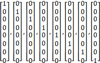
with
the scaling factor of
![]() .
.
R1-2302007������� FL Summary SRI/TPMI Enhancements Third Round�������� Moderator (InterDigital, Inc.)
From Thursday session
Agreement
For NCB-based 8TX PUSCH
transmission with ![]() , where
, where ![]() �is the number of
configured single-port SRS resources in a resource set,
�is the number of
configured single-port SRS resources in a resource set,
For
![]() , Rel-15 SRI indication
is reused
, Rel-15 SRI indication
is reused
Agreement
For CB-based 8TX PUSCH transmission, where Mode 2 uplink full power transmission (if supported) is not used, re-use legacy Rel-15 mechanism, that is
� when only one SRS resource in a resource set is configured, the SRI field in DCI is absent,
� when two SRS resources are configured in a resource set, 1 bit of SRI field in DCI is used to indicate the selected SRS resource in the set.
Agreement
For partially coherent uplink precoding by an 8TX UE codebook,
Agreement
For partially coherent uplink precoding by an 8TX UE codebook, Ng=2,
� Following rank and layer splitting cases are supported
|
Rank |
All layers in one Antenna Group |
Layers split across 2 Antenna Groups |
|
1 |
(1,0), (0,1) |
- |
|
8 |
- |
(4,4) |
� Select from the following cases based on the performance and overall DCI overhead
|
Rank |
All layers in one Antenna Group |
Layers split across 2 Antenna Groups |
|
2 |
(2,0), (0,2) |
- |
|
2 |
- |
(1,1) |
|
3 |
(3,0), (0,3) |
- |
|
3 |
- |
(2,1), (1,2) |
|
4 |
(4,0), (0,4) |
- |
|
4 |
- |
(2,2), (3,1), (1,3) |
|
5 |
- |
(4,1), (1,4), (2,3), (3,2) |
|
6 |
- |
(4,2), (2,4), (3,3) |
|
7 |
- |
(4,3), (3,4) |
Note: Above is not relevant to how precoders are indicated.
Please refer to RP-223276 for detailed scope of the WI.
Including extension for indication of multiple DL/UL TCI states, simultaneous multi-panel UL transmission, and power control for UL single DCI.
R1-2302299�������� Unified TCI Enhancements for MTRP���������� InterDigital, Inc.
R1-2302311�������� Unified TCI framework extension for multi-TRP������� FUTUREWEI
R1-2302370�������� Discussion on unified TCI framework extension for multi-TRP������������� Huawei, HiSilicon
R1-2302396�������� Unified TCI framework extension for multi-TRP������� Panasonic
R1-2302411�������� Unified TCI framework extension for multi-TRP������� Ericsson
R1-2302416�������� Enhancements on unified TCI framework extension for multi-TRP������� ZTE
R1-2302469�������� Further discussion on unified TCI framework extension for multi-TRP� vivo
R1-2302532�������� Unified TCI framework extension for multi-TRP������� OPPO
R1-2302585�������� Discussion on unified TCI framework extension for multi-TRP������������� Spreadtrum Communications
R1-2302635�������� Multi-TRP enhancements for the unified TCI framework�������� Fraunhofer IIS
R1-2302680�������� Further discussion on unified TCI framework extension for multi-TRP operation�������������� CATT
R1-2302723�������� Discussion of unified TCI framework for multi-TRP� Lenovo
R1-2302780�������� Unified TCI Framework for Multi-TRP������� Intel Corporation
R1-2302900�������� Discussion on unified TCI framework extension for multi-TRP������������� Fujitsu
R1-2302959�������� Unified TCI framework extension for multi-TRP������� xiaomi
R1-2303005�������� Unified TCI framework extension for multi-TRP������� Nokia, Nokia Shanghai Bell
R1-2303068�������� Unified TCI framework extension for multi-TRP/panel����������� LG Electronics
R1-2303110�������� Views on unified TCI extension focusing on m-TRP� Samsung
R1-2303178�������� Unified TCI framework extension for multi-TRP������� Sharp
R1-2303216�������� Discussion on unified TCI framework extension for multi-TRP������������� CMCC
R1-2303300�������� Discussion on Unified TCI framework extension for multi-TRP������������ CEWiT
R1-2303359�������� Unified TCI framework extension for multi-TRP������� MediaTek Inc.
R1-2303372�������� Discussion on unified TCI framework extension for multi-TRP������������� Transsion Holdings
R1-2303393�������� Discussion on unified TCI framework extension for multi-TRP operation����������� TCL Communication Ltd.
R1-2303405�������� Discussion on unified TCI framework extension for multi-TRP������������� FGI
R1-2303467�������� Unified TCI framework extension for multi-TRP������� Apple
R1-2303516�������� Discussion on unified TCI framework extension for multi-TRP������������� Google
R1-2303573�������� Extension of unified TCI framework for mTRP���������� Qualcomm Incorporated
R1-2303665�������� Discussion on unified TCI framework extension for multi-TRP������������� NEC
R1-2303697�������� Discussion on unified TCI framework extension for multi-TRP������������� NTT DOCOMO, INC.
R1-2303778�������� Discussion on unified TCI framework extension for multi-TRP������������� ITRI
R1-2303805�������� Discussion on unified TCI framework extension for M-TRP operation� Hyundai Motor Company
R1-2303806�������� Summary of pre-meeting offline discussion on extension of unified TCI framework�������������� Moderator (MediaTek Inc.)
[112bis-e-R18-MIMO-01] � Darcy (MediaTek)
Email discussion on unified TCI framework extension for multi-TRP by April 26th
- Check points: April 21, April 26
R1-2303807������� Moderator summary on extension of unified TCI framework (Round 0)�������������� Moderator (MediaTek Inc.)
From April 17th GTW session
Conclusion
On unified TCI framework extension for S-DCI based MTRP operation, there is no consensus to support dynamic switching between single-TRP operation and multi-TRP operation for channels/signals based on the number of TCI states mapped to the received TCI codepoint in DCI format 1_1/1_2
� FFS: How to switch between Rel-17 sTRP operation and Rel-18 mTRP operation
Agreement
On unified TCI framework extension, the Rel-17 timeline for updating the indicated joint/DL/UL TCI state(s) is retained, i.e., the indicated joint/DL/UL TCI state(s) applied to the DL reception or UL transmission in each slot is updated based on the Rel-17 beam application time
Agreement
On unified TCI framework extension for S-DCI based MTRP, the UE shall apply the first indicated joint/UL TCI state to PUSCH transmission(s) scheduled/activated by DCI format 0_0 (including DG and Type2 CG).
Agreement
On unified TCI framework extension for S-DCI based MTRP, an RRC configuration is provided to a Type1 CG configuration to inform that the UE shall apply the first, the second, or both indicated joint/UL TCI states to the corresponding CG-PUSCH transmission
o For TDM based PUSCH Tx scheme, the UE shall apply the first indicated joint/UL TCI state to the PUSCH transmission occasions(s) associated with the first SRS resource set for CB/NCB, and the second indicated joint/UL TCI state to the PUSCH transmission occasions(s) associated with the second SRS resource set for CB/NCB
o FFS: SDM and SFN based PUSCH Tx schemes
Decision: As per email decision posted on April 19th,
Agreement
On unified TCI framework extension for S-DCI based MTRP, PDSCH-CJT Tx scheme is RRC-configured, and dynamic switching between PDSCH-CJT and other S-DCI based PDSCH Tx schemes is not supported.
Decision: As per email decision posted on April 20th,
Agreement
If
the UE is configured with SSB-MTC-AdditionalPCI and receives TCI state
activation command (MAC-CE) that activates a set of joint/DL /UL TCI state(s)
specific to each coresetPoolIndex value for M-DCI based MTRP in
unified TCI framework extension, the activated joint/DL /UL TCI state(s)
specific to one coresetPoolIndex value can be is associated
with the serving cell PCI and the activated joint/DL /UL TCI state(s) specific
to another coresetPoolIndex value can be associated with a PCI other than the
serving cell PCI .
� Note: How to implement above in specification is up to spec editor.
Agreement
On unified TCI framework extension for M-DCI based MTRP , after NW response to TRP-specific BFR request to a BFD-RS set associated with a coresetPoolIndex value, QCL assumption/spatial Tx filter/PL-RS for channel(s)/signal(s) that applies the indicated joint/DL /UL TCI state specific to the coresetPoolIndex value are updated according to the new beam (q new ) corresponding to the BFD-RS set.
Decision: As per email decision posted on April 21st,
Agreement
On unified TCI framework extension for S-DCI based MTRP, the presence of the [TCI selection field] can be RRC-configured per DL BWP
� FFS: Whether the presence of the [TCI selection field] can be configured individually for DCI format 1_1 and DCI format 1_2 in the same DL BWP
R1-2303812������� Moderator summary on extension of unified TCI framework (Round 1)�������������� Moderator (MediaTek Inc.)
From April 21st GTW session
Agreement
On unified TCI framework extension for S-DCI based MTRP operation, support the followings:
� For a serving cell configured with joint DL/UL TCI mode, a full-set or any sub-set of {first joint TCI state, second joint TCI state} can be mapped to a TCI codepoint of the existing TCI field in a DCI format 1_1/1_2 by TCI state activation command (MAC-CE)
� For a serving cell configured with separate DL/UL TCI mode, a full-set or any sub-set of {first DL TCI state, first UL TCI state, second DL TCI state, second UL TCI state} can be mapped to a TCI codepoint of the existing TCI field in a DCI format 1_1/1_2 by TCI state activation command (MAC-CE)
� TCI state activation command (MAC-CE) should indicate that each joint/DL/UL TCI state mapped to a TCI codepoint is the first or second joint/DL/UL TCI state (detail on how to indicate above is up to RAN2 design)
� The first/second indicated joint/DL/UL TCI state(s) is updated according to the corresponding first/second joint/DL/UL TCI state(s) mapped to the TCI codepoint received by the UE
o If the UE receives a TCI codepoint mapped with a sub-set of {first joint TCI state, second joint TCI state} or {first DL TCI state, first UL TCI state, second DL TCI state, second UL TCI state}, the UE shall update the first/second indicated joint/DL/UL TCI state(s) according to the first/second joint/DL/UL TCI state(s) in the subset and keep other indicated first/second joint/DL/UL TCI state(s) that is not updated by the received TCI codepoint
Agreement
On unified TCI framework extension for M-DCI based MTRP, support at least Opt2 for PUCCH transmission, and Opt1 is not supported
� Note: Opt3 and Opt4 are not precluded
R1-2303814������� Moderator summary on extension of unified TCI framework (Round 2)�������������� Moderator (MediaTek Inc.)
From April 25th GTW session
Conclusion
On unified TCI framework extension for S-DCI based MTRP, there is no consensus in RAN1 on whether to reuse the Rel-17 RRC parameter followUnifiedTCIstate as a part of the RRC configuration that informs the UE shall apply the first one, the second one, both, or none of the indicated joint/DL TCI states to a CORESET
� Above does not impact how RAN2 writes their specifications
Agreement
On unified TCI framework extension for S-DCI based MTRP, an RRC configuration can be provided in CSI-AssociatedReportConfigInfo of CSI-AperiodicTrigger State for each CSI-RS resource set or for each CSI-RS resource in each aperiodic CSI-RS resource set to inform that the UE shall apply the first or the second indicated joint/DL TCI state to the CSI-RS resource if the aperiodic CSI-RS resource set for CSI/BM is configured to follow unified TCI state
� Above applies at least if the offset between the last symbol of the PDCCH carrying the triggering DCI and the first symbol of the aperiodic CSI-RS resources in the aperiodic CSI-RS resource set is equal to or larger than a threshold (if the threshold is needed)
� FFS: If the UE is configured for CSI-RS resource set, for an aperiodic CSI-RS resource set configured with two Resource Groups for NCJT CSI and configured to follow unified TCI state, if above RRC configuration is not provided to the aperiodic CSI-RS resource set, the UE shall apply the first indicated joint/DL TCI state to the CSI-RS resource(s) in Group 1 and the second indicated joint/DL TCI state to the CSI-RS resource(s) in Group 2.
� �per CSI-RS resource set� or �per CSI-RS resource� is up to UE capability
Agreement
On unified TCI framework extension, support the following cases for CA operation:
Decision: As per email decision posted on April 26th,
Agreement
On unified TCI framework extension for M-DCI based MTRP, an RRC configuration is provided to a Type1 CG configuration to inform that the UE shall apply the first or the second indicated joint/UL TCI state to the corresponding CG-PUSCH transmission, where the first and the second indicated joint/DL TCI states correspond to the indicated joint/UL TCI states specific to coresetPoolIndex value 0 and value 1, respectively.
Final summary in R1-2304235.
R1-2302300�������� Enhanced mTRP Operation with Multiple TA������������ InterDigital, Inc.
R1-2302312�������� Enhancements to support two TAs for multi-DCI������ FUTUREWEI
R1-2302371�������� Study on TA enhancement for UL M-TRP transmssion������������ Huawei, HiSilicon
R1-2302412�������� Two TAs for multi-DCI��� Ericsson
R1-2302417�������� TA enhancement for multi-DCI������ ZTE
R1-2302470�������� Further discussion on two TAs for multi-DCI-based multi-TRP operation����������� vivo
R1-2302533�������� Two TAs for multi-DCI based multi-TRP operation�� OPPO
R1-2302586�������� Discussion on two TAs for multi-DCI based multi-TRP����������� Spreadtrum Communications
R1-2302681�������� Discussion on two TAs for UL multi-DCI for multi-TRP operation������� CATT
R1-2302724�������� Discussion of two TAs for multi-DCI UL transmission������������ Lenovo
R1-2302781�������� On two TAs for multi-DCI Intel Corporation
R1-2302960�������� Discussion on two TAs for multi-TRP operation�������� xiaomi
R1-2303006�������� Two TAs for UL multi-DCI multi-TRP operation������ Nokia, Nokia Shanghai Bell
R1-2303040�������� Discussion on two TAs for multi-DCI based on multi-TRP operation���� TCL Communication Ltd.
R1-2303069�������� Two TAs for multi-TRP/panel�������� LG Electronics
R1-2303111�������� Views on two TAs for m-DCI��������� Samsung
R1-2303179�������� Two TAs for multi-DCI��� Sharp
R1-2303217�������� Discussion on two TAs for multi-DCI���������� CMCC
R1-2303360�������� UL Tx Timing Management for MTRP Operation����� MediaTek Inc.
R1-2303373�������� Discussion on two TAs for multi-DCI based multi-TRP operation��������� Transsion Holdings
R1-2303468�������� Views on two TAs for multi-DCI Uplink Transmissions���������� Apple
R1-2303517�������� Discussion on two TAs for multi-DCI���������� Google
R1-2303574�������� Supporting two TAs for multi-DCI based mTRP�������� Qualcomm Incorporated
R1-2303666�������� Discussion on two TAs for multi-DCI���������� NEC
R1-2303698�������� Discussion on two TAs for multi-DCI���������� NTT DOCOMO, INC.
[112bis-e-R18-MIMO-02] � Siva (Ericsson)
Email discussion on two TAs for multi-DCI by April 26th
- Check points: April 21, April 26
R1-2304055������� Moderator Summary #1 on Two TAs for multi-DCI����������� Moderator (Ericsson)
From April 19th GTW session
Working Assumption
For intra-cell multi-DCI based Multi-TRP operation with two TA enhancement, support the case where a PDCCH order sent by TRPX triggers RACH procedure towards either TRPX or TRPY.
� FFS: details of PRACH power control
Agreement
For multi-DCI based Multi-TRP operation with two TA enhancement, support at least RAR-based solution where RAR is only received from a TRP that is associated with Type 1 CSS
Decision: As per email decision posted on April 21st,
Agreement
For intercell multi-DCI based Multi-TRP operation with two TA enhancement, support indication of which PRACH configuration to be used in the RACH procedure in the PDCCH order.
� FFS: Whether additionalPCI or a generic identifier is indicated in PDCCH order
� FFS: The detail of the indication in PDCCH order in terms of whether to support PRACH triggered for inactive additionalPCI.
Decision: As per email decision posted on April 25th,
Conclusion
For multi-DCI based Multi-TRP operation with two TA enhancement, how to indicate the TAG ID via absolute TA command MAC CE is left up to RAN2:
� One of two TAG IDs configured in the SpCell can be indicated.
Agreement
For intra-cell multi-DCI based Multi-TRP operation with two TA enhancement, down-select one of the following alternatives:
Decision: As per email decision posted on April 26th,
Agreement
For multi-DCI based inter-cell multi-TRP and intra-cell multi-TRP operation with two TAGs configured in a CC, for a CFRA based PDCCH order from one TRP triggering PRACH towards another TRP, study whether and, if needed, how to determine the transmit power of the triggered PRACH preamble.
Including CSI enhancement for high/medium UE velocities and coherent JT (CJT).
R1-2302301�������� Further Details on CSI for CJT and Medium/High UE Velocities���������� InterDigital, Inc.
R1-2302372�������� CSI enhancement for coherent JT and mobility���������� Huawei, HiSilicon
R1-2303893�������� CSI enhancement for high/medium UE velocities and CJT������ ZTE������� (rev of R1-2302418)
R1-2302471�������� Further discussion on CSI enhancement for high-medium UE velocities and coherent JT���������� vivo
R1-2302534�������� CSI enhancement for high/medium UE velocities and coherent JT�������� OPPO
R1-2302587�������� Discussion on CSI enhancement for high/medium UE velocities and coherent JT�������������� Spreadtrum Communications
R1-2302636�������� CSI enhancements for medium UE velocities and coherent JT Fraunhofer IIS
R1-2302682�������� Discussion on CSI enhancement for high/medium UE velocities and coherent JT�������������� CATT
R1-2302725�������� Discussion of CSI enhancement for high speed UE and coherent JT������ Lenovo
R1-2302782�������� On CSI enhancements������ Intel Corporation
R1-2302839�������� Views on CSI enhancement for high/medium UE velocities and CJT���� Sony
R1-2302901�������� Discussion on Rel-18 MIMO CSI enhancement��������� Fujitsu
R1-2302961�������� CSI enhancement for high/medium UE velocities and CJT������ Xiaomi
R1-2303007�������� CSI enhancement for high/medium UE velocities and CJT������ Nokia, Nokia Shanghai Bell
R1-2303044�������� On CSI Enhancement������� Google
R1-2303070�������� Potential CSI enhancement for high/medium UE velocities and coherent JT�������� LG Electronics
R1-2303084�������� Discussion on CSI enhancement���� Mavenir
R1-2304066�������� Views on CSI enhancements���������� Samsung������������� (rev of R1-2303901 (rev of R1-2303114))
R1-2303191�������� CSI enhancement Sharp
R1-2303218�������� Discussion on CSI enhancement for high/medium UE velocities and CJT�������������� CMCC
R1-2303328�������� CSI Enhancements������������ MediaTek Inc.
R1-2303469�������� Views on Rel-18 MIMO CSI enhancement�� Apple
R1-2303575�������� CSI enhancements for medium UE velocities and Coherent-JT Qualcomm Incorporated
R1-2303650�������� Views on CSI Enhancements for CJT����������� AT&T
R1-2303677�������� Discussion on CSI enhancement���� NEC
R1-2303699�������� Discussion on CSI enhancement���� NTT DOCOMO, INC.
R1-2303783�������� On CSI enhancements for Rel-18 NR MIMO evolution����������� Ericsson
R1-2303113�������� Summary of OFFLINE discussion on Rel-18 MIMO CSI��������� Moderator (Samsung)
[112bis-e-R18-MIMO-03] � Eko (Samsung)
Email discussion on CSI enhancement by April 26th
- Check points: April 21, April 26
R1-2303112������� Moderator summary on Rel-18 CSI enhancements Moderator (Samsung)
From April 17th GTW session
Agreement
On the Parameter Combination of Type-II codebook refinement for CJT mTRP, only the following linkages are supported (marked �x�), for Rel-16 eType-II based
|
NTRP |
SD combo |
FD combo {pv}, |
|||||
|
{1/8, 1/8, 1/16, 1/16}, � |
{1/8, 1/8, 1/16, 1/16}, � |
{1/4, �, 1/8, 1/8}, � |
{1/4, �, 1/8, 1/8}, � |
{1/4, �, �, �}, � |
{1/2, �, �, �}, � |
||
|
1 |
2 |
|
|
x |
x |
|
|
|
4 |
|
|
x |
x |
x |
|
|
|
6 w/ restriction |
|
|
|
x |
x |
|
|
|
2 |
{2,2} |
x |
|
|
|
|
|
|
{2,4} {4,2} |
x |
|
|
|
|
�
|
|
|
{4,4} |
|
x |
|
x |
|
x |
|
|
3 |
{2,2,2} |
x |
x |
|
|
|
|
|
{2,2,4} {2,4,2} {4,2,2} |
x |
x |
� �
|
|
|
� �
|
|
|
{4,4,4} |
x |
x |
x |
x |
x |
x |
|
|
4 |
{2,2,2,2} |
x |
|
|
|
|
N/A |
|
{2,2,2,4} |
x |
|
|
|
|
N/A |
|
|
{2,2,4,4} |
|
|
|
x |
x |
N/A |
|
|
{4,4,4,4} |
|
x |
|
x |
x |
N/A |
|
Agreement
On the Type-II codebook refinement for CJT mTRP, regarding CBSR, amplitude restriction is CSI-RS-resource-specific.
� FFS: Whether CBSR is always configured for each CSI-RS resource or not
Conclusion
On the Type-II codebook refinement for CJT mTRP, regarding CBSR for NTRP>1, there is no consensus in supporting the additional optional soft amplitude restriction. Therefore, only hard amplitude restriction (per CSI-RS resource, based on the legacy design) is supported.
Agreement
On the Type-II codebook refinement
for CJT mTRP, for mode-1, support the use of per-CSI-RS-resource FD
basis selection offset (relative to a reference CSI-RS resource) for
independent FD basis selection across N CSI-RS resources, i.e. (example
formulation) ![]() �where:
�where:
Agreement
On the Parameter Combination of Type-II codebook refinement for CJT mTRP, for Rel-17 FeType-II based,
�
For ![]() =1, the Rel-17 legacy Parameter Combination is fully reused
=1, the Rel-17 legacy Parameter Combination is fully reused
� Regarding the combinations {M, beta}, it is proposed to reuse the legacy as below, with restriction on M=2.
|
M |
|
Condition |
|
1 |
� |
|
|
� |
|
|
|
1 |
|
|
|
2 |
� |
FFS: N_trp<=3, NL=1 |
|
� |
FFS: N_trp<=3, NL =1 |
Agreement
For the Type-II codebook refinement for high/medium velocities, when a UE is configured with X=2 for CQI calculation and reporting, the 2nd CQI is located in UCI part 2.
Agreement
For the Type-II codebook refinement for high/medium velocities, when WCSI>1, if a UE supports X=2 for CQI calculation, the value of X (either 1 or 2) is gNB-configured via higher-layer (RRC) signalling.
Agreement
For the Type-II codebook refinement for high/medium velocities, regarding the bitmap(s) for indicating the locations of the NZCs,
Agreement
For the Type-II codebook refinement for high/medium velocities based on Rel-16 eType-II regular codebook, at least the following Parameter Combinations are supported
|
|
|
|
|
|
|
|
||
|
4 |
1/4 |
1/4 |
1/4 |
|
4 |
1/4 |
1/4 |
1/2 |
|
4 (*) |
1/2 |
1/4 |
1/2 |
|
4 (*) |
1/4 |
1/4 |
3/4 |
|
6 (*) |
1/4 |
-- |
1/2 |
|
6 (*) |
1/4 |
-- |
3/4 |
(*) Note: From legacy. For L=6, the same restriction and UE optionality as legacy apply
|
|
|
|
|
|
|
|
||
|
2 |
1/8 |
1/16 |
1/4 |
|
2 |
1/8 |
1/16 |
1/2 |
|
2(*) |
� |
1/8 |
� |
|
2 (*) |
� |
1/8 |
� |
|
4 |
1/8 |
1/16 |
1/4 |
|
4 (*) |
� |
1/8 |
1/4 |
(*) Note: From legacy.
Agreement
For the Rel-18 TRS-based TDCP reporting, regarding the quantization of wideband normalized amplitude value,
Working Assumption
For the Rel-18 TRS-based TDCP reporting, for TDCP measurement and calculation,
Decision: As per email decision posted on April 18th,
Conclusion: On the Type-II codebook refinement for CJT mTRP, for Rel-16-based refinement, for NTRP>1, in addition to the supported SD combinations/permutations, there is no consensus on supporting at least one additional combination where at least one of the Ln values (n=1, �, NTRP) is 6.
Agreement
On the Type-II codebook refinement for high/medium velocities, regarding UCI omission, support reusing the legacy UCI omission mechanism with (Alt3) the following priority function: Prio(l,l,m,q)=2L.RI.Mv.q + 2L.RI.P(m)+ RI.l + l where P(m) = m
Agreement
For the Rel-18 TRS-based TDCP reporting, regarding the value of parameter Y for Y>1, the value of Y is gNB-configured via higher-layer (RRC) signalling.
Decision: As per email decision posted on April 19th,
Agreement
On the Type-II codebook refinement
for CJT mTRP, for mode-1, the layer-common reference CSI-RS resource ![]() �is fixed to the first of the N
selected CSI-RS resource(s).
�is fixed to the first of the N
selected CSI-RS resource(s).
� FFS: Whether more refined definition is needed for �the first�, e.g. related to the ordering of CSI-RS resources in the resource set, depending on RAN2 outcome.
Agreement
On the Parameter Combination of Type-II codebook refinement for CJT mTRP, for NTRP =1, in addition to the already agreed seven Parameter Combinations, support the following Parameter Combination (based on legacy Parameter Combination #6): L=4, {pv;b}={ �, �, � , �; � }.
Conclusion:
On the Parameter Combination of Type-II codebook refinement for CJT mTRP, no additional configuration signalling for indicating the linkage is needed. Per previous agreements (RAN1#111 and 112):
Such configuration shall be according to the supported/agreed linkages.
Conclusion:
On the Type-II codebook refinement for high/medium velocity, regarding CBSR, there is no consensus in supporting the additional optional soft amplitude restriction. Therefore, only hard amplitude restriction (based on the legacy design) is supported.
Agreement
For the Rel-18 TRS-based TDCP reporting, for TDCP measurement and calculation, confirm the following working assumption as an agreement with the following change
Agreement
For the Rel-18 TRS-based TDCP reporting, regarding the value of parameter Y, in addition to Y=1, support Y=2, 3, 4
Conclusion:
For the Rel-18 TRS-based TDCP reporting, there is no consensus on specifying a new priority rule. Therefore, the priority of the CSI report(s) associated with TDCP reporting is the same as CSI report(s) not carrying L1-RSRP or L1-SINR.
Decision: As per email decision posted on April 20th,
Agreement
On the Type-II codebook refinement for CJT mTRP, regarding CBSR, one of the NTRP configured CSI-RS resources must be configured with CBSR, while the remaining (NTRP �1) configured CSI-RS resources can be optionally configured with CBSR
� Note: if CBSR of one particular resource is absent, it means no restriction for SD basis selection for the resource.
Agreement
On the Type-II codebook refinement
for CJT mTRP, regarding UCI omission, support reusing the legacy UCI omission
mechanism while (Alt3) replacing
SD basis index l in legacy Prio calculation with ![]() , i.e., SD basis index
over all resources: Prio(l,l,m,n) = 2Ltot.RI.P(m)+ RI.
, i.e., SD basis index
over all resources: Prio(l,l,m,n) = 2Ltot.RI.P(m)+ RI.![]() +RI.l(n)+ l
+RI.l(n)+ l
� FFS: FD permutation P(.) as Rel-16-analogous, or no permutation i.e. P(m)=m
Agreement
For the Rel-18 TRS-based TDCP reporting,
� Support the following D (delay) values: 4 symbols, 1 slot, 2 slots, 3 slots, 4 slots, 5 slots
� Working assumption: Support the following D (delay) values in a separate UE Feature Group: 6 slots, 10 slots
FFS: The value of Dbasic
FFS: Applicability of each D value candidate for different SCS values and/or other parameters (e.g. Y, quantization)
Decision: As per email decision posted on April 21st,
Conclusion
On the Parameter Combination of Type-II codebook refinement for CJT mTRP, for Rel-17 FeType-II based, there is no consensus on introducing restriction �NTRP≤3, NL =1� for M=2.
Conclusion
On the Type-II codebook refinement for CJT mTRP, regarding CBSR for NTRP=1, there is no consensus in supporting the additional optional soft amplitude restriction. Therefore, only hard amplitude restriction (per CSI-RS resource, based on the legacy design) is supported.
Agreement
For the Type-II codebook refinement for high/medium velocities based on Rel-16 eType-II regular codebook, in addition to the already agreed six Parameter Combinations, the following three Parameter Combinations are supported:
|
|
|
|
|
|
|
|
||
|
2 |
1/8 |
1/16 |
� |
|
2 (*) |
� |
1/8 |
� |
|
4 (*) |
� |
1/8 |
� |
Agreement
For the Rel-18 TRS-based TDCP reporting, regarding the quantization of wideband normalized amplitude value, down-select (by RAN1#113) from the following candidates:
Once an alternative is selected, reducing the number of candidate values for s is not precluded.
Companies can simulate each alternative with and without a configurable center threshold.
R1-2304065������� Moderator Summary#3 on Rel-18 CSI enhancements: Round 2������� Moderator (Samsung)
From April 21st GTW session
Agreement
For the Type-II codebook refinement for high/medium velocities, when a UE is configured with X=2 for CQI calculation and reporting, the 2nd CQI includes 4-bit wideband CQI and 2-bit sub-bands CQIs calculated independently from the 1st CQI
Agreement
On the Type-II codebook refinement for high/medium velocities, regarding UCI omission
Agreement
On the Parameter Combination of Type-II codebook refinement for CJT mTRP, for Rel-17 FeType-II based, only the following an combinations are supported (after pruning):�
|
NTRP |
|
|
2 |
{1/2,1/2} |
|
{1/2,1}, {1,1/2} |
|
|
{3/4,3/4} |
|
|
{1,1} |
|
|
3 |
{1/2, 1/2, 1/2} |
|
{1/2, 1/2, 3/4}, and its permutations |
|
|
{1/2, 1/2, 1}, and its permutations |
|
|
{1, 1, 1} |
|
|
4 |
{1/2, 1/2, 1/2, 1/2} |
|
{1/2, 1/2, 1/2, 1} and its permutations |
|
|
{1/2, 1/2, 1, 1} |
|
|
{1, 1, 1, 1} |
Conclusion
There is no consensus on the optional bitmap for Q=2
Decision: As per email decision posted on April 25th,
Agreement
On the Type-II codebook refinement for CJT mTRP, regarding UCI omission, reuse the Rel-16 eType-II (legacy) permutation function P(m).
Agreement
For the Rel-18 Type-II codebook refinement for CJT mTRP,
Agreement
For the Rel-18 Type-II codebook refinement for CJT mTRP, regarding CSI calculation and measurement,
- For the configured NTRP CSI-RS resources comprising the CMR, the restriction specified for Rel-17 NCJT CSI is fully reused, i.e. the configured NTRP CSI-RS resources are located either in the same slot or two consecutive slots
- On PDSCH EPRE assumption for CQI calculation, down-select between the two alternatives:
o Alt1. The UE can assume that the PDSCH EPRE for a given CSI-RS port follows the configured powerControlOffset value associated with its respective CSI-RS resource
o Alt2. The UE can assume that the PDSCH EPRE for a given CSI-RS port follows a commonly configured powerControlOffset value for all the N selected CSI-RS resources
o Alt3. The UE can assume that the PDSCH EPRE for a given CSI-RS port follows a commonly configured powerControlOffset value defined as averagePDSCH-to-averageCSIRS EPRE ratio, where averagePDSCH and averageCSIRS are average power across for all the N selected CSI-RS resources
o Alt4. The UE can assume that the PDSCH EPRE divided by N for a given CSI-RS port follows a commonly configured powerControlOffset value for all the N selected CSI-RS resources
o Alt 5: The UE can assume that the PDSCH EPRE for a given CSI-RS port follows the powerControlOffset value for one of the configured NTRP CSI-RS resources
o Note: In legacy specification, different CSI-RS resources can be configured with different powerControlOffset values
- Decide, in RAN1#113, whether an ordering of CSI-RS port indices (e.g. according to the CSI-RS resource ID in TS38.331) for CSI calculation needs to be specified or not
Note: The total number of CSI-RS
ports summed across N selected (out of the configured NTRP)
CSI-RS resources will be used in the TS38.214
equation for CSI calculation
Agreement
On the Type-II codebook refinement for CJT mTRP, regarding the required number of CPUs and the values of Z/Z�, decide, in RAN1#113, at least based on the following factors:
Conclusion
For the Rel-18 Type-II codebook refinement for CJT mTRP, regarding the supported values of NL, there is no consensus in adding new value(s) (e.g. NL=3) to, or removing any value from the agreed NL ={1,2,4}.
Conclusion
On the Type-II codebook refinement for CJT mTRP, regarding the codebook parameter R, there is no consensus on supporting R=4.
Conclusion
For the Rel-18 Type-II codebook refinement for CJT mTRP, regarding interference measurement, beyond that supported in legacy specification, there is no consensus on supporting any additional enhancement on IMR (including the configuration for NZP CSI-RS for interference measurement or CSI-IM in relation to the configured CMR(s)).
Agreement
On the Type-II codebook refinement
for high/medium velocities, regarding UCI omission, when the configured value
of N4 is >12, the DD basis selection indicator is placed
in G1.
Agreement
For the Type-II codebook refinement for high/medium velocities,
Agreement
For the Rel-18 Type-II codebook refinement for high/medium velocities, regarding CSI calculation and measurement,
- The number of CSI-RS ports is the same for all the K configured CSI-RS resources comprising the CMR and the antenna ports for the same antenna port index across the K CSI-RS resources are the same.
- All the K configured CSI-RS resources comprising the CMR share the same BW and RE locations
- For interference measurement, legacy specification is fully reused, including the configuration for NZP CSI-RS for interference measurement or CSI-IM in relation to the configured CMR, i.e. only one NZP CSI-RS resource for interference measurement or only one CSI-IM resource can be configured irrespective of the value of K
- On PDSCH EPRE assumption for CQI calculation, a same powerControlOffset value is assumed for all the K configured CSI-RS resources comprising the CMR
o Alt 1: The configured powerControlOffset value is the same for all the K configured CSI-RS resources comprising the CMR
o Alt 2: The assumed PDSCH EPRE of all the K CSI-RS resources follows the configured powerControlOffset value of one fixed CSI-RS resource, e.g. the first one
Note: This may imply
that existing
section 5.2.2.2.75
of TS38.214 can apply to Rel-18 Type-II Doppler
codebook in terms of Rel-18 CMR (burst of CSI-RS resources) and Rel-18 CSI
reference resource.
Agreement
For the Type-II codebook refinement for high/medium velocities, regarding the required number and/or occupation time of CPUs, the values of Z/Z�, and total number active/simultaneous CSI-RS resource/ports, decide, in RAN1#113, at least based on the following factors:
-
The
measurement of K>1 CSI-RS resources for
Type-II CSI required to perform UE-side prediction, UE-side prediction based on multiple CSI-RS occasion(s) before
CSI triggering (FFS whether to support), CSI-RS occasion(s) after CSI triggering and, when the
configured N4 value is >1, DD compression (when the configured N4 value is >1)
Decision: As per email decision posted on April 26th,
Conclusion
On the Type-II codebook refinement for CJT mTRP, the lists of UCI parameters (along with the description of each parameter) are given in Table 1C, 1D, and 1E.
� Note: The manner in which the UCI parameters are captured is up to the spec editors
Table 1C: UCI parameter list for Rel-16 based
|
Parameter |
UCI |
Details/description |
Status |
|
# NZ coefficients |
Part 1 |
RI (�{1,�, RIMAX}) and KNZ,TOT (the total number of non-zero coefficients summed across all the layers and all N CSI-RS resources, where KNZ,TOT �{1,2,�, 2K0} are reported in UCI part 1 |
Complete |
|
Wideband CQI |
Part 1 |
Same as R15 |
Complete |
|
Subband CQI |
Part 1 |
Same as R15 |
Complete |
|
CSI-RS resource selection bitmap |
Part 1 |
Only reported when NTRP >1: NTRP-bit bitmap to indicate the UE recommendation of N CSI-RS resources - Non-existent if the value of N is RRC-configured to NTRP |
Complete |
|
Indication of number of SD basis vectors {L1, �, LNTRP} |
Part 1 |
UE recommendation selecting one of the NL
RRC-configured value combinations ( - Non-existent if NL=1 |
Complete |
|
N Bitmap(s) per layer |
Part 2 |
For RI=1-4: for layer l and
CSI-RS resource n, size- �where n denotes the n-th CSI-RS resource |
Complete |
|
Strongest coefficient indicator (SCI) |
Part 2 |
RI=1:
A RI>1: See Table 1E below |
Complete |
|
SD basis subset selection indicator for each of the N CSI-RS resources |
Part 2 |
SD
basis subset selection indicator is a |
Complete |
|
FD basis subset selection indicator |
Part 2 |
Mode-1: See Table �SCI and FD basis subset selection
indicator� below + (N � 1) FD basis selection
window offset values
Mode-2: See Table 1E �SCI and FD basis subset selection indicator� below |
Mode-1 complete Mode-2 complete |
|
LC coefficients: phase |
Part 2 |
Quantized independently across layers |
Complete |
|
LC coefficients: amplitude |
Part 2 |
Alt1 (agreed): Quantized independently across layers (including a reference amplitude for weaker polarization, for each layer)
Alt3 (WA): Quantized independently across layers (including 2N-1 reference amplitudes for 2N-1 (polarization, CSI-RS resource) pairs excluding the pair of (polarization, CSI-RS resource) associated with the SCI, for each layer) |
WA on Alt3 support needs to be confirmed or reverted |
|
SD oversampling (rotation) factor q1, q2 |
Part 2 |
Values of q1,n, q2,n follow Rel.15, reported per CSI RS resource |
Complete |
Table 1D: UCI parameter list for Rel-17 based
|
Parameter |
UCI |
Details/description |
Status |
|
# NZ coefficients |
Part 1 |
RI (�{1,�, RIMAX}) and KNZ,TOT (the total number of non-zero coefficients summed across all the layers and all N CSI-RS resources, where KNZ,TOT �{1,2,�, 2K0} are reported in UCI part 1 |
Complete |
|
Wideband CQI |
Part 1 |
Same as R15 |
Complete |
|
Subband CQI |
Part 1 |
Same as R15 |
Complete |
|
CSI-RS resource selection bitmap |
Part 1 |
NTRP-bit bitmap to indicate the UE recommendation of N CSI-RS resources - Non-existent if the value of N is RRC-configured to NTRP |
Complete |
|
Indication of number of selected ports {L1, �, LNTRP}, where Ln=n PCSI-RS /2 |
Part 1 |
UE recommendation selecting one of the NL
RRC-configured value combinations ( - Non-existent if NL=1 |
Complete |
|
N Bitmap(s) per layer |
Part 2 |
For
layer l and CSI-RS resource n,
size- |
Complete |
|
Strongest coefficient indicator (SCI) |
Part 2 |
For
layer l: A |
Complete |
|
Port selection indicator for each of the N CSI-RS resources |
Part 2 |
Port
selection indicator is a |
Complete |
|
FD basis subset selection indicator |
Part 2 |
Mode-1: See Mode-2+ (N � 1) FD basis selection window
offset values
Mode-2: a |
Mode-1 complete Mode-2 complete |
|
LC coefficients: phase |
Part 2 |
Quantized independently across layers |
Complete |
|
LC coefficients: amplitude |
Part 2 |
Alt1 (agreed): Quantized independently across layers (including a reference amplitude for weaker polarization, for each layer)
Alt3 (WA): Quantized independently across layers (including 2N-1 reference amplitudes for 2N-1 (polarization, CSI-RS resource) pairs excluding the pair of (polarization, CSI-RS resource) associated with the SCI, for each layer) |
WA on Alt3 support needs to be confirmed or reverted |
Table 1E: SCI and FD basis subset selection indicator for Rel-16-based Type-II CJT
|
SCI and FD basis subset selection indicator |
|
|
SCI for RI>1 |
Per-layer
SCI defined across N CSI-RS resources, where |
|
Index remapping |
For
layer Informative note (for the purpose of reference procedure): The
index |
|
Combinatorial
indicator for |
|
|
Combinatorial
indicator for |
|
|
|
Reported
in UCI part 2, |
(*) The red highlight parts are the new components in Rel-18.
Conclusion
For the Type-II codebook refinement for high/medium velocities, there is no consensus on supporting the following additional features when the value of N4 is 1 (or configured to 1):
� X=2 TD CQIs
� Additional constraint on the value of d: only d=1 is allowed
Conclusion
On the Type-II codebook refinement for high/medium velocities, the lists of UCI parameters (along with the description of each parameter) are given in Table 3C, 3D, and 3E.
� Note: The manner in which the UCI parameters are captured is up to the spec editors
Table 3C: UCI parameter list for Rel-16 based
|
Parameter |
UCI |
Details/description |
Status |
|
# NZ coefficients |
Part 1 |
RI (�{1,�, RIMAX}) and KNZ,TOT (the total number of non-zero coefficients summed across all the Q selected DD basis and across all the layers, are reported in UCI part 1 |
Complete |
|
Wideband CQI |
Part 1 |
Same as R15 |
Complete |
|
Subband CQI |
Part 1 |
Same as R15 |
Complete |
|
Wideband CQI for the second TD CQI |
Part 2 |
Only applicable for X=2 (same format as CQIs for 2CW when RI>4 in R15) |
Complete |
|
Subband CQI for the second TD CQI |
Part 2 |
Only applicable for X=2 (same format as CQIs for 2CW when RI>4 in R15) |
Complete |
|
Q Bitmap(s) per layer |
Part 2 |
Q bitmaps where each bitmap has the same format/design as R16 eType-II |
Complete |
|
Strongest coefficient indicator (SCI) |
Part 2 |
RI=1:
A RI>1: See Table 3E below |
Complete |
|
SD basis subset selection indicator |
Part 2 |
SD
basis subset selection indicator is a |
Complete |
|
FD basis subset selection indicator |
Part 2 |
Details follow Rel.16 (Table 3E above) |
Complete |
|
DD basis subset selection indicator (per layer) |
Part 2 |
Reported only when N4>2 and Q=2: the selection of Q
out of N4 DD basis vectors is indicated by a |
Complete |
|
LC coefficients: phase |
Part 2 |
Quantized independently across layers |
Complete
|
|
LC coefficients: amplitude |
Part 2 |
Quantized independently across layers (including a reference amplitude for weaker polarization, for each layer) |
Complete
|
|
SD oversampling (rotation) factor q1, q2 |
Part 2 |
Values of q1, q2 follow Rel.15 |
Complete |
Table 3D: UCI parameter list for Rel-17 based
|
Parameter |
UCI |
Details/description |
Status |
|
# NZ coefficients |
Part 1 |
RI (�{1,�, RIMAX}) and KNZ,TOT (the total number of non-zero coefficients summed across all the layers, are reported in UCI part 1 |
Complete |
|
Wideband CQI |
Part 1 |
Same as R15 |
Complete |
|
Subband CQI |
Part 1 |
Same as R15 (only X=1 TD CQI is supported)
|
Complete |
|
Bitmap per layer |
Part 2 |
Same as R17 eType-II |
Complete |
|
Strongest coefficient indicator (SCI) |
Part 2 |
For
layer l: A |
Complete |
|
Port selection indicator |
Part 2 |
Port
selection indicator is a |
Complete |
|
FD basis subset selection indicator |
Part 2 |
a |
Complete |
|
LC coefficients: phase |
Part 2 |
Quantized independently across layers |
Complete
|
|
LC coefficients: amplitude |
Part 2 |
Quantized independently across layers (including a reference amplitude for weaker polarization, for each layer) |
Complete
|
Table 3E: SCI and FD basis subset selection indicator for Rel-16-based Type-II Doppler
|
SCI and FD basis subset selection indicator |
|
|
SCI for RI>1 |
Per-layer
SCI defined across Q DD basis vectors, where |
|
Index remapping |
For
layer Informative note (for the purpose of reference procedure): The
index |
|
Combinatorial
indicator for |
|
|
Combinatorial
indicator for |
|
|
|
Reported
in UCI part 2, , |
(*) The red highlighted parts are the new components in Rel-18
Agreement
For the Rel-18 TRS-based TDCP reporting, for TDCP measurement and calculation, at least the following restrictions are supported:
Agreement
For the Rel-18 TRS-based TDCP reporting, regarding phase quantization, down-select (by RAN1#113) from the following candidates:
The evaluation should consider the impact of delay tracking operation at the UE where the phase difference between two slots can be close to zero.
Note: This proposal doesn�t preclude the UE supporting only smaller delay values (e.g. 4-symbol only) for the phase report (which is already optional).
Conclusion
For the Type-II codebook refinement for
high/medium velocities, regarding SCI definition, there is no consensus on
supporting the index remapping scheme analogous to that for FD basis for DD
basis. Therefore, ![]() �is a
�is a ![]() �bit indicator where
�bit indicator where ![]() �and Q is the number of DD basis vectors (1 or 2).
�and Q is the number of DD basis vectors (1 or 2).
Final summary in R1-2304122.
Including increasing orthogonal DMRS ports for UL/DL MU-MIMO and 8 Tx UL SU-MIMO.
R1-2302302�������� Remaining Details on DMRS Enhancements InterDigital, Inc.
R1-2302313�������� On increasing the number of orthogonal DM-RS ports for MU-MIMO�������������� FUTUREWEI
R1-2302373�������� Discussion on DMRS enhancements in Rel-18����������� Huawei, HiSilicon
R1-2302419�������� DMRS enhancement for UL/DL MU-MIMO and 8 Tx UL SU-MIMO�� ZTE, China Telecom
R1-2302428�������� Discussions on increased number of orthogonal DMRS ports�� New H3C Technologies Co., Ltd.
R1-2302472�������� Further discussion on DMRS enhancements vivo
R1-2302535�������� DMRS enhancement for Rel-18 MIMO�������� OPPO
R1-2302588�������� Discussion on increased number of orthogonal DMRS ports��� Spreadtrum Communications
R1-2302634�������� On increased number of orthogonal DMRS ports������� Fraunhofer IIS
R1-2302683�������� DMRS enhancements in Rel-18����� CATT
R1-2302726�������� Discussion of increased number of orthogonal� DMRS ports��� Lenovo
R1-2302767�������� On increased number of orthogonal DMRS ports for MU-MIMO and 8 Tx UL SU-MIMO�� Ericsson
R1-2302783�������� DMRS Enhancements for Rel-18 NR����������� Intel Corporation
R1-2302962�������� Discussion on DMRS enhancement Xiaomi
R1-2303008�������� Rel-18 UL and DL DMRS Enhancements���� Nokia, Nokia Shanghai Bell
R1-2303045�������� On DMRS Enhancement�� Google
R1-2303071�������� Increased number of orthogonal DMRS ports������������� LG Electronics
R1-2303115�������� Views on DMRS enhancements����� Samsung
R1-2303180�������� Increased number of orthogonal DMRS ports������������� Sharp
R1-2303219�������� Discussion on increased number of orthogonal DMRS ports��� CMCC
R1-2303329�������� Increased number of orthogonal DMRS ports������������� MediaTek Inc.
R1-2303470�������� Views on supporting increased number of orthogonal DMRS ports������� Apple
R1-2303576�������� Design for increased number of orthogonal DMRS ports��������� Qualcomm Incorporated
R1-2303678�������� Discussion on increased number of orthogonal DMRS ports��� NEC
R1-2303700�������� Discussion on DMRS enhancements������������ NTT DOCOMO, INC.
[112bis-e-R18-MIMO-04] � Yuki (NTT DOCOMO)
Email discussion on increased number of orthogonal DMRS ports by April 26th
- Check points: April 21, April 26
Decision: As per email decision posted on April 19th,
R18 DMRS port tables for sDCI mTRP PDSCH
Agreement (eType1, maxLength1)
For RAN1#111 agreement of the antenna ports indication in Rel.18 eType1 DMRS ports with maxLength = 1 for PDSCH, for S-DCI based M-TRP,
� Support all rows of DMRS port combinations and Number of DMRS CDM group(s) without data for Rel.18 eType1 DMRS ports with maxLength = 1 for PDSCH for S-TRP, in addition to row 30 for 1CW in RAN1#112 agreement.
o If MU-MIMO restriction (i.e. UE does not expect to be multiplexed with other DMRS ports in the same CDM group) is introduced to certain row(s) for S-TRP, the MU-restriction is applied to the same row(s) for S-DCI based M-TRP.
Agreement (eType1, maxLength2)
For the antenna ports indication in Rel.18 eType1 DMRS ports with maxLength = 2 for PDSCH, for S-DCI based M-TRP case, support all the following rows of DMRS port combinations and Number of DMRS CDM group(s) without data.
� All rows for Rel.18 eType1 DMRS ports with maxLength = 2 for PDSCH for S-TRP.
o If MU-MIMO restriction (i.e. UE does not expect to be multiplexed with other DMRS ports in the same CDM group) is introduced to certain row(s) for S-TRP, the MU-restriction is applied to the same row(s) for S-DCI based M-TRP.
� For one CW, add new row 68 in Table 7.3.1.2.2-2A-X.
o For row 68, introduce MU-MIMO restriction (i.e. UE does not expect to be multiplexed with other DMRS ports in the same CDM group).
Table 7.3.1.2.2-2A-X: Antenna port(s) (1000 + DMRS port), dmrs-Type=eType1, maxLength=2
|
One Codeword: Codeword 0 enabled, Codeword 1 disabled |
|||
|
Value |
Number of DMRS CDM group(s) without data |
DMRS port(s) |
Number of front-load symbols |
|
� |
� |
� |
� |
|
68 |
2 |
0,2,3 |
1 |
Agreement (eType2, maxLength1)
For the antenna ports indication in Rel.18 eType2 DMRS ports with maxLength = 1 for PDSCH, for S-DCI based M-TRP case, support all the following rows of DMRS port combinations and Number of DMRS CDM group(s) without data.
� All rows for Rel.18 eType2 DMRS ports with maxLength = 1 for PDSCH for S-TRP.
o If MU-MIMO restriction (i.e. UE does not expect to be multiplexed with other DMRS ports in the same CDM group) is introduced to certain row(s) for S-TRP, the MU-restriction is applied to the same row(s) for S-DCI based M-TRP.
� For one CW, add new row 60 in Table 7.3.1.2.2-3A-X.
o For row 60, introduce MU-MIMO restriction (i.e. UE does not expect to be multiplexed with other DMRS ports in the same CDM group).
Table 7.3.1.2.2-3A-X: Antenna port(s) (1000 + DMRS port), dmrs-Type=eType2, maxLength=1
|
One Codeword: Codeword 0 enabled, Codeword 1 disabled |
||
|
Value |
Number of DMRS CDM group(s) without data |
DMRS port(s) |
|
� |
� |
� |
|
60 |
2 |
0,2,3 |
Agreement (eType2, maxLength2)
For the antenna ports indication in Rel.18 eType2 DMRS ports with maxLength = 2 for PDSCH, for S-DCI based M-TRP case, support all the following rows of DMRS port combinations and Number of DMRS CDM group(s) without data.
� All rows for Rel.18 eType2 DMRS ports with maxLength = 2 for PDSCH for S-TRP.
o If MU-MIMO restriction (i.e. UE does not expect to be multiplexed with other DMRS ports in the same CDM group) is introduced to certain row(s) for S-TRP, the MU-restriction is also applied to the same row(s) for S-DCI based M-TRP.
� For one CW, add new row 128 in Table 7.3.1.2.2-4A-X.
o For row 128, introduce MU-MIMO restriction (i.e. UE does not expect to be multiplexed with other DMRS ports in the same CDM group).
Table 7.3.1.2.2-4A-X: Antenna port(s) (1000 + DMRS port), dmrs-Type=eType2, maxLength=2
|
One Codeword: Codeword 0 enabled, Codeword 1 disabled |
|||
|
Value |
Number of DMRS CDM group(s) without data |
DMRS port(s) |
Number of front-load symbols |
|
� |
� |
� |
� |
|
128 |
2 |
0,2,3 |
1 |
PUSCH with rank >4
Agreement
Confirm the following Working Assumption in RAN1#112 at least for NCB based PUSCH:
� To support PUSCH with rank = 5-8, support the following for enhancement of DMRS port allocation tables.
o Option 1: Separate DMRS ports tables for rank 5,6,7,8 for each of eType1/eType2 and maxLength=1/2 (similar to the current UL DMRS ports table).
� FFS: whether/how to reuse the reserved field in antenna ports field for other purposes can be discussed in AI9.1.4.2 [or AI9.1.3.1].
� Note: The above Working Assumption for CB based PUSCH may be confirmed later.
Agreement
For
8Tx PUSCH, specify the factor related to PUSCH to PTRS power ratio per layer
per RE (![]() ) based on the following principles.
) based on the following principles.
R1-2303884������� FL summary#1 on DMRS������������� Moderator (NTT DOCOMO)
From April 19th GTW session
Agreement
For RAN1#111 agreement of the antenna ports indication in Rel.18 eType1 DMRS ports with maxLength = 1 for PDSCH, at least for S-TRP case,
� For 2 CWs,
o Alt.1: Confirm the working assumption in RAN1#112 with modification (in red).
� Alt.3-1: Support at least row 0-3 for 2 CWs in Table 4-0.
Table 4-0: DMRS ports for 2CWs.
|
Two Codewords: Codeword 0 enabled, Codeword 1 enabled |
||
|
Value |
Number of DMRS CDM group(s) without data |
DMRS port(s) |
|
0 |
2 |
0,1,2,3,8 |
|
1 |
2 |
0,1,2,3,8,10 |
|
2 |
2 |
0,1,2,3,8,9,10 |
|
3 |
2 |
0,1,2,3,8,9,10,11 |
|
[4] |
[2] |
[0,1,2,3,10] |
|
[5] |
[2] |
[0,1,8,2,3,10] |
|
[6] |
[2] |
[0,1,8,2,3,10,11] |
|
[7] |
[2] |
[0,1,8,9,2,3,10,11] |
|
[8] |
[2] |
[0,2,3,8,9] |
|
[9] |
[2] |
[0,1,2,3,8,9] |
FFS: Additional rows (rows 4~9) if there is technical justification.
Agreement
For RAN1#111 agreement of the antenna ports indication in Rel.18 eType1 DMRS ports with maxLength = 1 for PDSCH, at least for S-TRP case,
|
One Codeword: Codeword 0 enabled, Codeword 1 disabled |
||
|
Value |
Number of DMRS CDM group(s) without data |
DMRS port(s) |
|
|
|
|
|
|
|
|
Decision: As per email decision posted on April 21st,
Working Assumption
� Adopt Table 7.3.1.1.2-12B/13B/14B/15B/16B/17B/20B/21B/22B/23B to support signalling >4 ranks PUSCH with Rel-15 DMRS ports at least for full or non-coherent UL codebook based PUSCH and non-codebook based PUSCH.
� FFS: Whether/how some of bits in the antenna ports field can be reused for other purpose for >4 ranks PUSCH.
Table 7.3.1.1.2-12B: Antenna port(s), transform precoder is disabled, dmrs-Type=1, maxLength=2, rank = 5
|
Value |
Number of DMRS CDM group(s) without data |
DMRS port(s) |
Number of front-load symbols |
|
0 |
2 |
0-4 |
2 |
|
1-15 |
Reserved |
Reserved |
Reserved |
Table 7.3.1.1.2-13B: Antenna port(s), transform precoder is disabled, dmrs-Type= 1, maxLength=2, rank = 6
|
Value |
Number of DMRS CDM group(s) without data |
DMRS port(s) |
Number of front-load symbols |
|
0 |
2 |
0,1,2,3,4,6 |
2 |
|
1-15 |
Reserved |
Reserved |
Reserved |
Table 7.3.1.1.2-14B: Antenna port(s), transform precoder is disabled, dmrs-Type= 1, maxLength=2, rank = 7
|
Value |
Number of DMRS CDM group(s) without data |
DMRS port(s) |
Number of front-load symbols |
|
0 |
2 |
0,1,2,3,4,5,6 |
2 |
|
1-15 |
Reserved |
Reserved |
Reserved |
Table 7.3.1.1.2-15B: Antenna port(s), transform precoder is disabled, dmrs-Type= 1, maxLength=2, rank = 8
|
Value |
Number of DMRS CDM group(s) without data |
DMRS port(s) |
Number of front-load symbols |
|
0 |
2 |
0,1,2,3,4,5,6,7 |
2 |
|
1-15 |
Reserved |
Reserved |
Reserved |
Table 7.3.1.1.2-16B: Antenna port(s), transform precoder is disabled, dmrs-Type= 2, maxLength=1, rank=5
|
Value |
Number of DMRS CDM group(s) without data |
DMRS port(s) |
|
0 |
3 |
0-4 |
|
1-15 |
Reserved |
Reserved |
Table 7.3.1.1.2-17B: Antenna port(s), transform precoder is disabled, dmrs-Type= 2, maxLength=1, rank=6
|
Value |
Number of DMRS CDM group(s) without data |
DMRS port(s) |
|
0 |
3 |
0-5 |
|
1-15 |
Reserved |
Reserved |
Table 7.3.1.1.2-20B: Antenna port(s), transform precoder is disabled, dmrs-Type= 2, maxLength=2, rank=5
|
Value |
Number of DMRS CDM group(s) without data |
DMRS port(s) |
Number of front-load symbols |
|
0 |
3 |
0-4 |
1 |
|
1 |
2 |
0,1,2,3,6 |
2 |
|
12-31 |
Reserved |
Reserved |
Reserved |
Table 7.3.1.1.2-21B: Antenna port(s), transform precoder is disabled, dmrs-Type= 2, maxLength=2, rank=6
|
Value |
Number of DMRS CDM group(s) without data |
DMRS port(s) |
Number of front-load symbols |
|
0 |
3 |
0-5 |
1 |
|
1 |
2 |
0,1,2,3,6,8 |
2 |
|
2-31 |
Reserved |
Reserved |
Reserved |
Table 7.3.1.1.2-22B: Antenna port(s), transform precoder is disabled, dmrs-Type= 2, maxLength=2, rank=7
|
Value |
Number of DMRS CDM group(s) without data |
DMRS port(s) |
Number of front-load symbols |
|
0 |
2 |
0,1,2,3,6,7,8 |
2 |
|
1-31 |
Reserved |
Reserved |
Reserved |
Table 7.3.1.1.2-23B: Antenna port(s), transform precoder is disabled, dmrs-Type= 2, maxLength=2, rank=8
|
Value |
Number of DMRS CDM group(s) without data |
DMRS port(s) |
Number of front-load symbols |
|
0 |
2 |
0,1,2,3,6,7,8,9 |
2 |
|
1-31 |
Reserved |
Reserved |
Reserved |
Agreement
For > 4 layers PUSCH with Rel.18 eType 1/eType 2 DMRS ports, support at least the same DMRS port combination(s) as that for rank = 5,6,7,8 for PDSCH with Rel.18 eType 1/eType 2 DMRS ports at least for full or non-coherent UL codebook based PUSCH and non-codebook based PUSCH.
Decision: As per email decision posted on April 24th,
Agreement
For the antenna ports indication in Rel.18 eType1 DMRS ports with maxLength = 2 for PDSCH, at least for S-TRP case, support all rows of DMRS port combinations and Number of DMRS CDM group(s) without data in Table 7.3.1.2.2-2-X.
� FFS: For row 9-11, 24-30, 55-60, and 81-83 (if agreed) in one CW, introduce MU-MIMO restriction (i.e. UE does not expect to be multiplexed with other DMRS ports in the same CDM group) or UE capability.
� FFS: The total number of rows for eType1 DMRS ports with maxLength =2 for PDSCH at least for S-TRP case does not exceed 64.
Table 7.3.1.2.2-2-X: Antenna port(s) (1000 + DMRS port), dmrs-Type=eType1, maxLength=2
|
One Codeword: Codeword 0 enabled, Codeword 1 disabled |
Two Codewords: Codeword 0 enabled, Codeword 1 enabled |
||||||
|
Value |
Number of DMRS CDM group(s) without data |
DMRS port(s) |
Number of front-load symbols |
Value |
Number of DMRS CDM group(s) without data |
DMRS port(s) |
Number of front-load symbols |
|
0 |
1 |
0 |
1 |
[0 |
2 |
0-4 |
2] |
|
1 |
1 |
1 |
1 |
[1 |
2 |
0,1,2,3,4,6 |
2] |
|
2 |
1 |
0,1 |
1 |
[2 |
2 |
0,1,2,3,4,5,6 |
2] |
|
3 |
2 |
0 |
1 |
[3 |
2 |
0,1,2,3,4,5,6,7 |
2] |
|
4 |
2 |
1 |
1 |
4 |
2 |
0,1,2,3,8 |
1 |
|
5 |
2 |
2 |
1 |
5 |
2 |
0,1,2,3,8,10 |
1 |
|
6 |
2 |
3 |
1 |
6 |
2 |
0,1,2,3,8,9,10 |
1 |
|
7 |
2 |
0,1 |
1 |
7 |
2 |
0,1,2,3,8,9,10,11 |
1 |
|
[8 |
2 |
2,3 |
1] |
[8 |
1 |
0,1,4,5,8 |
2] |
|
[9 |
2 |
0-2 |
1] |
[9 |
1 |
0,1,4,5,8,12 |
2] |
|
[10 |
2 |
0-3 |
1] |
[10 |
1 |
0,1,4,5,8,9,12 |
2] |
|
[11 |
2 |
0,2 |
1] |
[11 |
1 |
0,1,4,5,8,9,12,13 |
2] |
|
12 |
2 |
0 |
2 |
[12 |
2 |
0,1,4,5,8 |
2] |
|
13 |
2 |
1 |
2 |
[13 |
2 |
0,1,4,5,8,12 |
2] |
|
14 |
2 |
2 |
2 |
[14 |
2 |
0,1,4,5,8,9,12 |
2] |
|
15 |
2 |
3 |
2 |
[15 |
2 |
0,1,4,5,8,9,12,13 |
2] |
|
16 |
2 |
4 |
2 |
[16 |
2 |
2,3,6,7,10 |
2] |
|
17 |
2 |
5 |
2 |
[17 |
2 |
2,3,6,7,10,14 |
2] |
|
18 |
2 |
6 |
2 |
[18 |
2 |
2,3,6,7,10,11,14 |
2] |
|
19 |
2 |
7 |
2 |
[19 |
2 |
2,3,6,7,10,11,14,15 |
2] |
|
20 |
2 |
0,1 |
2 |
[20 |
2 |
0,1, 2,3,10 |
1] |
|
21 |
2 |
2,3 |
2 |
[21 |
2 |
0,1,8,2,3,10 |
1] |
|
22 |
2 |
4,5 |
2 |
[22 |
2 |
0,1,8, 2,3,10,11 |
1] |
|
23 |
2 |
6,7 |
2 |
[23 |
2 |
0,1,8,9,2,3,10,11 |
1] |
|
[24 |
2 |
0,4 |
2] |
[24 |
1 |
0,1,4,5,12 |
2] |
|
[25 |
2 |
2,6 |
2] |
[25 |
1 |
0,1,8,4,5,12 |
2] |
|
[26 |
2 |
0,1,4 |
2] |
[26 |
1 |
0,1,8,4,5,12,13 |
2] |
|
[27 |
2 |
2,3,6 |
2] |
[27 |
1 |
0,1,8,9,4,5,12,13 |
2] |
|
[28 |
2 |
0,1,4,5 |
2] |
[28 |
2 |
0,1,4,5,12 |
2] |
|
[29 |
2 |
2,3,6,7 |
2] |
[29 |
2 |
0,1,8,4,5,12 |
2] |
|
[30 |
2 |
0,2,4,6 |
2] |
[30 |
2 |
0,1,8,4,5,12,13 |
2] |
|
31 |
1 |
8 |
1 |
[31 |
2 |
0,1,8,9,4,5,12,13 |
2] |
|
32 |
1 |
9 |
1 |
[32 |
2 |
2,3,6,7,14 |
2] |
|
33 |
1 |
8,9 |
1 |
[33 |
2 |
2,3,10,6,7,14 |
2] |
|
34 |
2 |
8 |
1 |
[34 |
2 |
2,3,10,6,7,14,15 |
2] |
|
35 |
2 |
9 |
1 |
[35 |
2 |
2,3,10,11,6,7,14,15 |
2] |
|
36 |
2 |
10 |
1 |
[36 |
2 |
0,2,3,8,9 |
1] |
|
37 |
2 |
11 |
1 |
[37 |
2 |
0,1,2,3,8,9 |
1] |
|
38 |
2 |
8,9 |
1 |
|
|
|
|
|
39 |
2 |
10,11 |
1 |
|
|
|
|
|
|
|
|
|
|
|
|
|
|
|
|
|
|
|
|
|
|
|
|
|
|
|
|
|
|
|
|
43 |
2 |
8 |
2 |
|
|
|
|
|
44 |
2 |
9 |
2 |
|
|
|
|
|
45 |
2 |
10 |
2 |
|
|
|
|
|
46 |
2 |
11 |
2 |
|
|
|
|
|
47 |
2 |
12 |
2 |
|
|
|
|
|
48 |
2 |
13 |
2 |
|
|
|
|
|
49 |
2 |
14 |
2 |
|
|
|
|
|
50 |
2 |
15 |
2 |
|
|
|
|
|
51 |
2 |
8,9 |
2 |
|
|
|
|
|
52 |
2 |
10,11 |
2 |
|
|
|
|
|
53 |
2 |
12,13 |
2 |
|
|
|
|
|
54 |
2 |
14,15 |
2 |
|
|
|
|
|
[55 |
2 |
8,12 |
2] |
|
|
|
|
|
[56 |
2 |
10,14 |
2] |
|
|
|
|
|
[57 |
2 |
8,9,12 |
2] |
|
|
|
|
|
[58 |
2 |
10,11,14 |
2] |
|
|
|
|
|
[59 |
2 |
8,9,12,13 |
2] |
|
|
|
|
|
[60 |
2 |
10,11,14,15 |
2] |
|
|
|
|
|
|
|
|
|
|
|
|
|
|
62 |
1 |
0,1,8 |
1 |
|
|
|
|
|
63 |
1 |
0,1,8,9 |
1 |
|
|
|
|
|
64 |
2 |
0,1,8 |
1 |
|
|
|
|
|
65 |
2 |
0,1,8,9 |
1 |
|
|
|
|
|
66 |
2 |
2,3,10 |
1 |
|
|
|
|
|
67 |
2 |
2,3,10,11 |
1 |
|
|
|
|
|
[69 |
1 |
0,1,8 |
2] |
|
|
|
|
|
[70 |
1 |
0,1,8,9 |
2] |
|
|
|
|
|
[71 |
1 |
4,5,12 |
2] |
|
|
|
|
|
[72 |
1 |
4,5,12,13 |
2] |
|
|
|
|
|
[73 |
2 |
0,1,8 |
2] |
|
|
|
|
|
[74 |
2 |
0,1,8,9 |
2] |
|
|
|
|
|
[75 |
2 |
4,5,12 |
2] |
|
|
|
|
|
[76 |
2 |
4,5,12,13 |
2] |
|
|
|
|
|
[77 |
2 |
2,3,10 |
2] |
|
|
|
|
|
[78 |
2 |
2,3,10,11 |
2] |
|
|
|
|
|
[79 |
2 |
6,7,14 |
2] |
|
|
|
|
|
[80 |
2 |
6,7,14,15 |
2] |
|
|
|
|
|
[81 |
2 |
5,8,9 |
2] |
|
|
|
|
|
[82 |
2 |
7,10,11 |
2] |
|
|
|
|
|
[83 |
2 |
7,12,13 |
2] |
|
|
|
|
Agreement
For the antenna ports indication in Rel.18 eType2 DMRS ports with maxLength = 1 for PDSCH, at least for S-TRP case, support all rows of DMRS port combinations and Number of DMRS CDM group(s) without data in Table 7.3.1.2.2-3-X.
� FFS: For rows 9, 10, 20-23, 33,34, 44-46, 60-62 (if agreed) in one CW, introduce MU-MIMO restriction (i.e. UE does not expect to be multiplexed with other DMRS ports in the same CDM group) or UE capability.
Table 7.3.1.2.2-3-X: Antenna port(s) (1000 + DMRS port), dmrs-Type=eType2, maxLength=1
|
One codeword: Codeword 0 enabled, Codeword 1 disabled |
Two codewords: Codeword 0 enabled, Codeword 1 enabled |
||||
|
Value |
Number of DMRS CDM group(s) without data |
DMRS port(s) |
Value |
Number of DMRS CDM group(s) without data |
DMRS port(s) |
|
0 |
1 |
0 |
0 |
3 |
0-4 |
|
1 |
1 |
1 |
1 |
3 |
0-5 |
|
2 |
1 |
0,1 |
[2 |
3 |
12-16] |
|
3 |
2 |
0 |
[3 |
3 |
12-17] |
|
4 |
2 |
1 |
4 |
2 |
0,1,2,3,12 |
|
5 |
2 |
2 |
5 |
2 |
0,1,2,3,12,14 |
|
6 |
2 |
3 |
6 |
2 |
0-3,12-14 |
|
7 |
2 |
0,1 |
7 |
2 |
0-3,12-15 |
|
8 |
2 |
2,3 |
[8 |
3 |
0,1,2,3,12] |
|
[9 |
2 |
0-2] |
[9 |
3 |
0,1,2,3,12,14] |
|
[10 |
2 |
0-3] |
[10 |
3 |
0-3,12-14] |
|
11 |
3 |
0 |
[11 |
3 |
0-3,12-15] |
|
12 |
3 |
1 |
[12 |
2 |
0,2,3,12,13] |
|
13 |
3 |
2 |
[13 |
2 |
0,1,2,3,14] |
|
14 |
3 |
3 |
[14 |
2 |
0,1,12,2,3,14] |
|
15 |
3 |
4 |
[15 |
2 |
0,1,12,2,3,14,15] |
|
16 |
3 |
5 |
[16 |
2 |
0,1,12,13,2,3,14,15] |
|
17 |
3 |
0,1 |
[17 |
3 |
0,1,2,3,14] |
|
18 |
3 |
2,3 |
[18 |
3 |
0,1,12,2,3,14] |
|
19 |
3 |
4,5 |
[19 |
3 |
0,1,12,2,3,14,15] |
|
[20 |
3 |
0-2] |
[20 |
3 |
0,1,12,13,2,3,14,15] |
|
[21 |
3 |
3-5] |
|
|
|
|
[22 |
3 |
0-3] |
|
|
|
|
[23 |
2 |
0,2] |
|
|
|
|
24 |
1 |
12 |
|
|
|
|
25 |
1 |
13 |
|
|
|
|
26 |
1 |
12,13 |
|
|
|
|
27 |
2 |
12 |
|
|
|
|
28 |
2 |
13 |
|
|
|
|
29 |
2 |
14 |
|
|
|
|
30 |
2 |
15 |
|
|
|
|
31 |
2 |
12,13 |
|
|
|
|
32 |
2 |
14,15 |
|
|
|
|
[33 |
2 |
12-14] |
|
|
|
|
[34 |
2 |
12-15] |
|
|
|
|
35 |
3 |
12 |
|
|
|
|
36 |
3 |
13 |
|
|
|
|
37 |
3 |
14 |
|
|
|
|
38 |
3 |
15 |
|
|
|
|
39 |
3 |
16 |
|
|
|
|
40 |
3 |
17 |
|
|
|
|
41 |
3 |
12,13 |
|
|
|
|
42 |
3 |
14,15 |
|
|
|
|
43 |
3 |
16,17 |
|
|
|
|
[44 |
3 |
12-14] |
|
|
|
|
[45 |
3 |
15-17] |
|
|
|
|
[46 |
3 |
12-15] |
|
|
|
|
|
|
|
|
|
|
|
48 |
1 |
0,1,12 |
|
|
|
|
49 |
1 |
0,1,12,13 |
|
|
|
|
50 |
2 |
0,1,12 |
|
|
|
|
51 |
2 |
0,1,12,13 |
|
|
|
|
52 |
2 |
2,3,14 |
|
|
|
|
53 |
2 |
2,3,14,15 |
|
|
|
|
54 |
3 |
0,1,12 |
|
|
|
|
55 |
3 |
0,1,12,13 |
|
|
|
|
56 |
3 |
2,3,14 |
|
|
|
|
57 |
3 |
2,3,14,15 |
|
|
|
|
58 |
3 |
4,5,16 |
|
|
|
|
59 |
3 |
4,5,16,17 |
|
|
|
|
[60 |
3 |
13,15,17] |
|
|
|
|
[61 |
3 |
13,15] |
|
|
|
|
[62 |
2 |
13,15] |
|
|
|
Agreement
For the antenna ports indication in Rel.18 eType2 DMRS ports with maxLength = 2 for PDSCH, at least for S-TRP case, support all rows of DMRS port combinations and Number of DMRS CDM group(s) without data in Table 7.3.1.2.2-4-X.
� FFS: For rows 9, 10, 20-23, 42-47, 67, 68, 78-80, 100-105, and 153-158 (if agreed) in one CW, introduce MU-MIMO restriction (i.e. UE does not expect to be multiplexed with other DMRS ports in the same CDM group) or UE capability.
Table 7.3.1.2.2-4-X: Antenna port(s) (1000 + DMRS port), dmrs-Type=eType2, maxLength=2
|
One codeword: Codeword 0 enabled, Codeword 1 disabled |
Two Codewords: Codeword 0 enabled, Codeword 1 enabled |
||||||
|
Value |
Number of DMRS CDM group(s) without data |
DMRS port(s) |
Number of front-load symbols |
Value |
Number of DMRS CDM group(s) without data |
DMRS port(s) |
Number of front-load symbols |
|
0 |
1 |
0 |
1 |
[0 |
3 |
0-4 |
1] |
|
1 |
1 |
1 |
1 |
[1 |
3 |
0-5 |
1] |
|
2 |
1 |
0,1 |
1 |
[2 |
2 |
0,1,2,3,6 |
2] |
|
3 |
2 |
0 |
1 |
[3 |
2 |
0,1,2,3,6,8 |
2] |
|
4 |
2 |
1 |
1 |
[4 |
2 |
0,1,2,3,6,7,8 |
2] |
|
5 |
2 |
2 |
1 |
[5 |
2 |
0,1,2,3,6,7,8,9 |
2] |
|
6 |
2 |
3 |
1 |
6 |
2 |
0,1,2,3,12 |
1 |
|
7 |
2 |
0,1 |
1 |
7 |
2 |
0-3,12,14 |
1 |
|
8 |
2 |
2,3 |
1 |
8 |
2 |
0-3,12-14 |
1 |
|
[9 |
2 |
0-2 |
1] |
9 |
2 |
0-3,12-15 |
1 |
|
[10 |
2 |
0-3 |
1] |
[10 |
3 |
0,1,2,3,12 |
1] |
|
11 |
3 |
0 |
1 |
[11 |
3 |
0-3,12,14 |
1] |
|
12 |
3 |
1 |
1 |
[12 |
3 |
0-3,12-14 |
1] |
|
13 |
3 |
2 |
1 |
[13 |
3 |
0-3,12-15 |
1] |
|
14 |
3 |
3 |
1 |
[14 |
1 |
0,1,6,7,12 |
2] |
|
15 |
3 |
4 |
1 |
[15 |
1 |
0,1,6,7,12,18 |
2] |
|
16 |
3 |
5 |
1 |
[16 |
1 |
0,1,6,7,12,13,18 |
2] |
|
17 |
3 |
0,1 |
1 |
[17 |
1 |
0,1,6,7,12,13,18,19 |
2] |
|
18 |
3 |
2,3 |
1 |
[18 |
2 |
0,1,6,7,12 |
2] |
|
19 |
3 |
4,5 |
1 |
[19 |
2 |
0,1,6,7,12,18 |
2] |
|
[20 |
3 |
0-2 |
1] |
[20 |
2 |
0,1,6,7,12,13,18 |
2] |
|
[21 |
3 |
3-5 |
1] |
[21 |
2 |
0,1,6,7,12,13,18,19 |
2] |
|
[22 |
3 |
0-3 |
1] |
[22 |
2 |
2,3,8,9,14 |
2] |
|
[23 |
2 |
0,2 |
1] |
[23 |
2 |
2,3,8,9,14,20 |
2] |
|
24 |
3 |
0 |
2 |
[24 |
2 |
2,3,8,9,14,15,20 |
2] |
|
25 |
3 |
1 |
2 |
[25 |
2 |
2,3,8,9,14,15,20,21 |
2] |
|
26 |
3 |
2 |
2 |
[26 |
3 |
0,1,6,7,12 |
2] |
|
27 |
3 |
3 |
2 |
[27 |
3 |
0,1,6,7,12,18 |
2] |
|
28 |
3 |
4 |
2 |
[28 |
3 |
0,1,6,7,12,13,18 |
2] |
|
29 |
3 |
5 |
2 |
[29 |
3 |
0,1,6,7,12,13,18,19 |
2] |
|
30 |
3 |
6 |
2 |
[30 |
3 |
2,3,8,9,14 |
2] |
|
31 |
3 |
7 |
2 |
[31 |
3 |
2,3,8,9,14,20 |
2] |
|
32 |
3 |
8 |
2 |
[32 |
3 |
2,3,8,9,14,15,20 |
2] |
|
33 |
3 |
9 |
2 |
[33 |
3 |
2,3,8,9,14,15,20,21 |
2] |
|
34 |
3 |
10 |
2 |
[34 |
3 |
4,5,10,11,16 |
2] |
|
35 |
3 |
11 |
2 |
[35 |
3 |
4,5,10,11,16,22 |
2] |
|
36 |
3 |
0,1 |
2 |
[36 |
3 |
4,5,10,11,16,17,22 |
2] |
|
37 |
3 |
2,3 |
2 |
[37 |
3 |
4,5,10,11,16,17,22,23 |
2] |
|
38 |
3 |
4,5 |
2 |
[38 |
2 |
0,1,2,3,14 |
1] |
|
39 |
3 |
6,7 |
2 |
[39 |
2 |
0,1,12,2,3,14 |
1] |
|
40 |
3 |
8,9 |
2 |
[40 |
2 |
0,1,12,2,3,14,15 |
1] |
|
41 |
3 |
10,11 |
2 |
[41 |
2 |
0,1,12,13,2,3,14,15 |
1] |
|
[42 |
3 |
0,1,6 |
2] |
[42 |
3 |
0,1,2,3,14 |
1] |
|
[43 |
3 |
2,3,8 |
2] |
[43 |
3 |
0,1,12,2,3,14 |
1] |
|
[44 |
3 |
4,5,10 |
2] |
[44 |
3 |
0,1,12,2,3,14,15 |
1] |
|
[45 |
3 |
0,1,6,7 |
2] |
[45 |
3 |
0,1,12,13,2,3,14,15 |
1] |
|
[46 |
3 |
2,3,8,9 |
2] |
[46 |
1 |
0,1,6,7,18 |
2] |
|
[47 |
3 |
4,5,10,11 |
2] |
[47 |
1 |
0,1,12,6,7,18 |
2] |
|
48 |
1 |
0 |
2 |
[48 |
1 |
0,1,12,6,7,18,19 |
2] |
|
49 |
1 |
1 |
2 |
[49 |
1 |
0,1,12,13,6,7,18,19 |
2] |
|
50 |
1 |
6 |
2 |
[50 |
2 |
0,1,6,7,18 |
2] |
|
51 |
1 |
7 |
2 |
[51 |
2 |
0,1,12,6,7,18 |
2] |
|
52 |
1 |
0,1 |
2 |
[52 |
2 |
0,1,12,6,7,18,19 |
2] |
|
53 |
1 |
6,7 |
2 |
[53 |
2 |
0,1,12,13,6,7,18,19 |
2] |
|
54 |
2 |
0,1 |
2 |
[54 |
2 |
2,3,8,9,20 |
2] |
|
55 |
2 |
2,3 |
2 |
[55 |
2 |
2,3,14,8,9,20 |
2] |
|
56 |
2 |
6,7 |
2 |
[56 |
2 |
2,3,14,8,9,20,21 |
2] |
|
57 |
2 |
8,9 |
2 |
[57 |
2 |
2,3,14,15,8,9,20,21 |
2] |
|
58 |
1 |
12 |
1 |
[58 |
3 |
0,1,6,7,18 |
2] |
|
59 |
1 |
13 |
1 |
[59 |
3 |
0,1,12,6,7,18 |
2] |
|
60 |
1 |
12,13 |
1 |
[60 |
3 |
0,1,12,6,7,18,19 |
2] |
|
61 |
2 |
12 |
1 |
[61 |
3 |
0,1,12,13,6,7,18,19 |
2] |
|
62 |
2 |
13 |
1 |
[62 |
3 |
2,3,8,9,20 |
2] |
|
63 |
2 |
14 |
1 |
[63 |
3 |
2,3,14,8,9,20 |
2] |
|
64 |
2 |
15 |
1 |
[64 |
3 |
2,3,14,8,9,20,21 |
2] |
|
65 |
2 |
12,13 |
1 |
[65 |
3 |
2,3,14,15,8,9,20,21 |
2] |
|
66 |
2 |
14,15 |
1 |
[66 |
3 |
4,5,10,11,22 |
2] |
|
[67 |
2 |
12-14 |
1] |
[67 |
3 |
4,5,16,10,11,22 |
2] |
|
[68 |
2 |
12-15 |
1] |
[68 |
3 |
4,5,16,10,11,22,23 |
2] |
|
69 |
3 |
12 |
1 |
[69 |
3 |
4,5,16,17,10,11,22,23 |
2] |
|
70 |
3 |
13 |
1 |
|
|
|
|
|
71 |
3 |
14 |
1 |
|
|
|
|
|
72 |
3 |
15 |
1 |
|
|
|
|
|
73 |
3 |
16 |
1 |
|
|
|
|
|
74 |
3 |
17 |
1 |
|
|
|
|
|
75 |
3 |
12,13 |
1 |
|
|
|
|
|
76 |
3 |
14,15 |
1 |
|
|
|
|
|
77 |
3 |
16,17 |
1 |
|
|
|
|
|
[78 |
3 |
12-14 |
1] |
|
|
|
|
|
[79 |
3 |
15-17 |
1] |
|
|
|
|
|
[80 |
3 |
12-15 |
1] |
|
|
|
|
|
|
|
|
|
|
|
|
|
|
82 |
3 |
12 |
2 |
|
|
|
|
|
83 |
3 |
13 |
2 |
|
|
|
|
|
84 |
3 |
14 |
2 |
|
|
|
|
|
85 |
3 |
15 |
2 |
|
|
|
|
|
86 |
3 |
16 |
2 |
|
|
|
|
|
87 |
3 |
17 |
2 |
|
|
|
|
|
88 |
3 |
18 |
2 |
|
|
|
|
|
89 |
3 |
19 |
2 |
|
|
|
|
|
90 |
3 |
20 |
2 |
|
|
|
|
|
91 |
3 |
21 |
2 |
|
|
|
|
|
92 |
3 |
22 |
2 |
|
|
|
|
|
93 |
3 |
23 |
2 |
|
|
|
|
|
94 |
3 |
12,13 |
2 |
|
|
|
|
|
95 |
3 |
14,15 |
2 |
|
|
|
|
|
96 |
3 |
16,17 |
2 |
|
|
|
|
|
97 |
3 |
18,19 |
2 |
|
|
|
|
|
98 |
3 |
20,21 |
2 |
|
|
|
|
|
99 |
3 |
22,23 |
2 |
|
|
|
|
|
[100 |
3 |
12,13,18 |
2] |
|
|
|
|
|
[101 |
3 |
14,15,20 |
2] |
|
|
|
|
|
[102 |
3 |
16,17,22 |
2] |
|
|
|
|
|
[103 |
3 |
12,13,18,19 |
2] |
|
|
|
|
|
[104 |
3 |
14,15,20,21 |
2] |
|
|
|
|
|
[105 |
3 |
16,17,22,23 |
2] |
|
|
|
|
|
106 |
1 |
12 |
2 |
|
|
|
|
|
107 |
1 |
13 |
2 |
|
|
|
|
|
108 |
1 |
18 |
2 |
|
|
|
|
|
109 |
1 |
19 |
2 |
|
|
|
|
|
110 |
1 |
12,13 |
2 |
|
|
|
|
|
111 |
1 |
18,19 |
2 |
|
|
|
|
|
112 |
2 |
12,13 |
2 |
|
|
|
|
|
113 |
2 |
14,15 |
2 |
|
|
|
|
|
114 |
2 |
18,19 |
2 |
|
|
|
|
|
115 |
2 |
20,21 |
2 |
|
|
|
|
|
116 |
1 |
0,1,12 |
1 |
|
|
|
|
|
117 |
1 |
0,1,12,13 |
1 |
|
|
|
|
|
118 |
2 |
0,1,12 |
1 |
|
|
|
|
|
119 |
2 |
0,1,12,13 |
1 |
|
|
|
|
|
120 |
2 |
2,3,14 |
1 |
|
|
|
|
|
121 |
2 |
2,3,14,15 |
1 |
|
|
|
|
|
122 |
3 |
0,1,12 |
1 |
|
|
|
|
|
123 |
3 |
0,1,12,13 |
1 |
|
|
|
|
|
124 |
3 |
2,3,14 |
1 |
|
|
|
|
|
125 |
3 |
2,3,14,15 |
1 |
|
|
|
|
|
126 |
3 |
4,5,16 |
1 |
|
|
|
|
|
127 |
3 |
4,5,16,17 |
1 |
|
|
|
|
|
[129 |
1 |
0,1,12 |
2] |
|
|
|
|
|
[130 |
1 |
0,1,12,13 |
2] |
|
|
|
|
|
[131 |
1 |
6,7,18 |
2] |
|
|
|
|
|
[132 |
1 |
6,7,18,19 |
2] |
|
|
|
|
|
[133 |
2 |
0,1,12 |
2] |
|
|
|
|
|
[134 |
2 |
0,1,12,13 |
2] |
|
|
|
|
|
[135 |
2 |
6,7,18 |
2] |
|
|
|
|
|
[136 |
2 |
6,7,18,19 |
2] |
|
|
|
|
|
[137 |
2 |
2,3,14 |
2] |
|
|
|
|
|
[138 |
2 |
2,3,14,15 |
2] |
|
|
|
|
|
[139 |
2 |
8,9,20 |
2] |
|
|
|
|
|
[140 |
2 |
8,9,20,21 |
2] |
|
|
|
|
|
[141 |
3 |
0,1,12 |
2] |
|
|
|
|
|
[142 |
3 |
0,1,12,13 |
2] |
|
|
|
|
|
[143 |
3 |
6,7,18 |
2] |
|
|
|
|
|
[144 |
3 |
6,7,18,19 |
2] |
|
|
|
|
|
[145 |
3 |
2,3,14 |
2] |
|
|
|
|
|
[146 |
3 |
2,3,14,15 |
2] |
|
|
|
|
|
[147 |
3 |
8,9,20 |
2] |
|
|
|
|
|
[148 |
3 |
8,9,20,21 |
2] |
|
|
|
|
|
[149 |
3 |
4,5,16 |
2] |
|
|
|
|
|
[150 |
3 |
4,5,16,17 |
2] |
|
|
|
|
|
[151 |
3 |
10,11,22 |
2] |
|
|
|
|
|
[152 |
3 |
10,11,22,23 |
2] |
|
|
|
|
|
[153 |
3 |
7,12,13 |
2] |
|
|
|
|
|
[154 |
3 |
9,14,15 |
2] |
|
|
|
|
|
[155 |
3 |
11,16,17 |
2] |
|
|
|
|
|
[156 |
3 |
9,18,19 |
2] |
|
|
|
|
|
[157 |
3 |
18,19,20 |
2] |
|
|
|
|
|
[158 |
3 |
21,22,23 |
2] |
|
|
|
|
Conclusion
No consensus to support MAC CE based switching between Rel.15 DMRS ports and Rel.18 DMRS ports for PDSCH.
Agreement
For Rel.18 eType1/eType2 DMRS ports with maxLength=1/2 for PDSCH/PUSCH, if Rel.18 eType1/eType2 DMRS ports is configured by RRC, the DCI size of antenna ports field in DCI format 1_1/1_2/0_1/0_2 is increased by at least 1-bit from Rel.17.
� Note: it does not preclude future possibility to support more than 1-bit, if RAN1 agree the necessity.
Agreement
For RAN1#112 agreement of the antenna ports indication in Rel.18 eType1 DMRS ports with maxLength = 1 for PUSCH.
� Support row 7 for rank2, row1 for rank3, row 1 for rank4.
Table 7.3.1.1.2-9-X: Antenna port(s), transform precoder is disabled, dmrs-Type= eType1, maxLength=1, rank = 2
|
Value |
Number of DMRS CDM group(s) without data |
DMRS port(s) |
|
7 |
2 |
9,11 |
Table 7.3.1.1.2-10-X: Antenna port(s), transform precoder is disabled, dmrs-Type= eType1, maxLength=1, rank = 3
|
Value |
Number of DMRS CDM group(s) without data |
DMRS port(s) |
|
1 |
2 |
8-10 |
Table 7.3.1.1.2-11-X: Antenna port(s), transform precoder is disabled, dmrs-Type= eType1, maxLength=1, rank = 4
|
Value |
Number of DMRS CDM group(s) without data |
DMRS port(s) |
|
1 |
2 |
8-11 |
Agreement
For two PTRS ports for partial/non-coherent PUSCH, PTRS-DMRS association for PUSCH with up to 8 layers is down selected from the following.
� Alt.1: The size of PTRS-DMRS association field is 4-bit in DCI format 0_1/0_2.
Table 1: PTRS-DMRS association for UL PTRS ports 0 and 1
|
Value of MSB |
DMRS port |
Value of LSB |
DMRS port |
|
0 |
1st DMRS port which shares PTRS port 0 |
0 |
1st DMRS port which shares PTRS port 1 |
|
1 |
2nd DMRS port which shares PTRS port 0 |
1 |
2nd DMRS port which shares PTRS port 1 |
|
2 |
3rd DMRS port which shares PTRS port 0 |
2 |
3rd DMRS port which shares PTRS port 1 |
|
3 |
4th DMRS port which shares PTRS port 0 |
3 |
4th DMRS port which shares PTRS port 1 |
o If the MCS is the same for two CWs, the PTRS port is associated with the first CW.
Table 2: PTRS-DMRS association for UL PTRS ports 0 and 1
|
Value of MSB |
DMRS port |
Value of LSB |
DMRS port |
|
0 |
1st DMRS port which shares PTRS port 0 |
0 |
1st DMRS port which shares PTRS port 1 |
|
1 |
2nd DMRS port which shares PTRS port 0 |
1 |
2nd DMRS port which shares PTRS port 1 |
o For PUSCH with rank 5-8, 2-bit of antenna ports field is reused in addition to 2-bit PTRS-DMRS association in DCI format 0_1/0_2, and total 4-bit is used for PTRS-DMRS association.
Table 1: PTRS-DMRS association for UL PTRS ports 0 and 1
|
Value of MSB |
DMRS port |
Value of LSB |
DMRS port |
|
0 |
1st DMRS port which shares PTRS port 0 |
0 |
1st DMRS port which shares PTRS port 1 |
|
1 |
2nd DMRS port which shares PTRS port 0 |
1 |
2nd DMRS port which shares PTRS port 1 |
|
2 |
3rd DMRS port which shares PTRS port 0 |
2 |
3rd DMRS port which shares PTRS port 1 |
|
3 |
4th DMRS port which shares PTRS port 0 |
3 |
4th DMRS port which shares PTRS port 1 |
� Alt.4: The size of PTRS-DMRS association field is 2-bit in DCI format 0_1/0_2.
Table 2: PTRS-DMRS association for UL PTRS ports 0 and 1
|
Value of MSB |
DMRS port |
Value of LSB |
DMRS port |
|
0 |
1st DMRS port which shares PTRS port 0 |
0 |
1st DMRS port which shares PTRS port 1 |
|
1 |
2nd DMRS port which shares PTRS port 0 |
1 |
2nd DMRS port which shares PTRS port 1 |
Decision: As per email decision posted on April 26th,
Conclusion
For MU-MIMO within a CDM group between Rel.15 DMRS ports and Rel.18 DMRS ports,
� For PUSCH, there is no restriction.
Agreement
For partial/non-coherent PUSCH with rank=5-8 transmission (i.e. non of the CWs is disabled) with one PTRS port, PTRS-DMRS association for PUSCH is the following.
Table 7.3.1.1.2-25: PTRS-DMRS association for UL PTRS port 0
|
Value |
DMRS port |
|
0 |
1st scheduled DMRS port with the CW |
|
1 |
2nd scheduled DMRS port with the CW |
|
2 |
3rd scheduled DMRS port with the CW |
|
3 |
4th scheduled DMRS port with the CW |
Conclusion
For �The CW with the higher MCS� in RAN1#112 agreement of PTRS-DMRS association field for full-coherent PUSCH with rank=5~8 PUSCH with one port PTRS, following is clarified.
� Note: in case of PUSCH retransmission, the initial MCS is used for CW selection.
Final summary in:
R1-2303885�������� FL summary#2 on DMRS Moderator (NTT DOCOMO)
R1-2302303�������� Enhancements on SRS for CJT and 8TX UEs������������� InterDigital, Inc.
R1-2302314�������� SRS enhancements for TDD CJT and 8TX operation FUTUREWEI
R1-2302374�������� Discussion on SRS enhancement for TDD CJT and UL 8Tx operation in Rel-18�������������� Huawei, HiSilicon
R1-2302420�������� SRS enhancement targeting TDD CJT and 8 TX operation������ ZTE
R1-2302473�������� Further discussion on SRS enhancements���� vivo
R1-2302536�������� SRS enhancement targeting TDD CJT and 8 TX operation������ OPPO
R1-2302580�������� Discussions on SRS enhancement in Rel-18 New H3C Technologies Co., Ltd.
R1-2302589�������� Discussion on SRS enhancement targeting TDD CJT and 8 TX operation�������������� Spreadtrum Communications
R1-2302684�������� Discussion on Rel-18 SRS enhancement������ CATT
R1-2302727�������� Discussion of SRS enhancement���� Lenovo
R1-2302776�������� On SRS enhancements targeting TDD CJT and 8 TX operation������������� Oy LM Ericsson AB
R1-2302784�������� Discussion on SRS enhancement in Rel-18�� Intel Corporation
R1-2302963�������� Discussion on SRS enhancements�� Xiaomi
R1-2303009�������� SRS enhancement for TDD CJT and 8Tx operation��� Nokia, Nokia Shanghai Bell
R1-2303046�������� On SRS Enhancement������ Google
R1-2303072�������� SRS enhancement targeting TDD CJT and 8 TX operation������ LG Electronics
R1-2303116�������� Views on SRS enhancements��������� Samsung
R1-2303170�������� Views on SRS enhancement targeting TDD CJT and 8 TX operation���� KDDI Corporation
R1-2303181�������� SRS enhancement targeting TDD CJT and 8 TX operation������ Sharp
R1-2303192�������� Discussion on SRS enhancement targeting TDD CJT� ETRI
R1-2303220�������� Discussion on SRS enhancement targeting TDD CJT and 8 TX operation�������������� CMCC
R1-2303471�������� Views on Rel-18 MIMO SRS enhancement� Apple
R1-2303577�������� SRS enhancement for TDD CJT and 8 Tx operation�� Qualcomm Incorporated
R1-2303679�������� Discussion on SRS enhancement��� NEC
R1-2303701�������� Discussion on SRS enhancement��� NTT DOCOMO, INC.
[112bis-e-R18-MIMO-05] � Jialing (Futurewei)
Email discussion on SRS enhancement targeting TDD CJT and 8 TX operation by April 26th
- Check points: April 21, April 26
Decision: As per email decision posted on April 19th,
Agreement
For an
8-port SRS resource in a SRS resource set with usage �codebook� or
�antennaSwitching�, when the 8 ports are mapped onto one or more OFDM symbols
using legacy schemes (repetition, frequency hopping, partial sounding, or a
combination thereof), and when the resource is assigned with ![]() >1 comb offsets, determine the
mapping from the ports to comb offsets as follows:
>1 comb offsets, determine the
mapping from the ports to comb offsets as follows:
�
If ![]() =2,
ports {1000, 1002, 1004, 1006} are mapped on the first comb offset, and {1001,
1003, 1005, 1007} on the second comb offset
=2,
ports {1000, 1002, 1004, 1006} are mapped on the first comb offset, and {1001,
1003, 1005, 1007} on the second comb offset
�
If ![]() =4,
ports {1000, 1004} are mapped on the first comb offset, {1001, 1005} on the
second comb offset, {1002, 1006} on the third comb offset, and {1003, 1007} on
the fourth comb offset.
=4,
ports {1000, 1004} are mapped on the first comb offset, {1001, 1005} on the
second comb offset, {1002, 1006} on the third comb offset, and {1003, 1007} on
the fourth comb offset.
Agreement
For
an 8-port SRS resource in a SRS resource set with usage �codebook� or
�antennaSwitching�, when the 8 ports are mapped onto one or more OFDM symbols
using legacy schemes (repetition, frequency hopping, partial sounding, or a
combination thereof), and when the resource is configured with comb ![]() �and with maximum
�and with maximum ![]() �cyclic shifts per comb offset, the
number of comb offset(s) and the cyclic shift locations are determined based on
the one RRC configured cyclic shift location
�cyclic shifts per comb offset, the
number of comb offset(s) and the cyclic shift locations are determined based on
the one RRC configured cyclic shift location ![]() �as follows:
�as follows:
�
If ![]() , then
1 comb offset is used, otherwise 2 comb offsets are used.
, then
1 comb offset is used, otherwise 2 comb offsets are used.
�
The 8 cyclic shift locations for the 8 ports
are {![]() ) mod
) mod ![]() ) mod
) mod ![]() ,
reusing the existing equation
,
reusing the existing equation ![]() �in
38.211 6.4.1.4.2.
�in
38.211 6.4.1.4.2.
R1-2304010������� FL Summary #1 on SRS enhancements���� Moderator (Futurewei)
From April 19th GTW session
Agreement
For a SRS resource configured with comb offset hopping and/or cyclic shift hopping,
Agreement
For an 8-port SRS resource in a SRS resource set with usage �codebook� or �antennaSwitching� and resource mapping based on TDM onto m ≥ 2 OFDM symbols in a slot and with TDM factor s, the s subsets of ports are mapped cyclically as {{1, 2, �, s}, �, {1, 2, �, s}} on the m OFDM symbols.
Decision: As per email decision posted on April 22nd,
Conclusion
No consensus on enhanced per-TRP power control and/or power control of one SRS towards to multiple TRPs in Rel-18.
R1-2304011������� FL Summary #2 on SRS enhancements���� Moderator (FUTUREWEI)
From April 25th GTW session
Agreement
For SRS comb offset hopping and/or cyclic
shift hopping, for a SRS resource, the hopping pattern initialization ID
determined by ![]() , where
, where ![]() �is a new ID for cyclic shift hopping and/or comb offset hopping.
�is a new ID for cyclic shift hopping and/or comb offset hopping.
� The range of the new ID is from 0 to 1023
Agreement
For a SRS resource configured with comb offset hopping, if the repetition factor R > 1, within a slot, the time-domain hopping behavior depends on the OFDM symbol index l' of each symbol or the first symbol across the R repetitions based on RRC configuration, and FFS configuration details.
� UE can indicate whether it supports one or both the options. Details to be discussed in UE feature.
Decision: As per email decision posted on April 25th,
Agreement
For SRS comb offset hopping / cyclic shift hopping, support reinitialization at the beginning of every N radio frame(s), where N ≥ 1.
� FFS: N is fixed or configurable.
Decision: As per email decision posted on April 26th,
Agreement
For an 8-port SRS resource in a SRS resource set with usage �codebook� or �antennaSwitching�, when the 8 ports are mapped onto one or more OFDM symbols using legacy schemes (repetition, frequency hopping, partial sounding, or a combination thereof), and when the resource is assigned with comb 4 or comb 8, decide one of the following options:
 .
. .
FFS equation details.
.
FFS equation details.
Agreement
For an 8-port SRS resource in a SRS resource set with usage �codebook� or �antennaSwitching� and resource mapping based on TDM with TDM factor s, when the s subsets of ports are mapped onto m ≥ 2 OFDM symbols in a slot according to the pattern {{1, 2, �, s}, �, {1, 2, �, s}} (totally m/s groups of {1, 2, �, s}), the SRS transmissions within each of the m/s groups of {1, 2, �, s} use the same set of subcarriers. If consecutive groups of {1, 2, �, s} are configured as repetition, then the SRS transmissions of the consecutive groups use the same set of subcarriers.
� Note: applicable to the SRS resource with or without FH/RPFS.
� FFS the scenario where comb offset hopping is configured for the SRS resource.
Agreement
For an 8-port SRS resource in a SRS resource set with usage �codebook� or �antennaSwitching� and with TDM factor s > 1, when the s subsets of ports are mapped onto m ≥ 2 OFDM symbols in a slot according to the pattern {{1, 2, �, s}, �, {1, 2, �, s}} (totally m/s groups of {1, 2, �, s}), and when the SRS transmission on a subset of the s OFDM symbols within a group of {1, 2, �, s} is dropped, study at least the following solutions:
� Whether or not a UE drops the SRS transmission on the rest of OFDM symbols within the group of {1, 2, �, s}, based on, for example, the usage, coherency, and/or repetition configuration.
� Whether or not a UE changes the transmission order of the subsets of ports.
Agreement
Whether SRS comb offset hopping can be combined with one of group / sequence hopping on a SRS resource depends on UE feature/capability design.
Final summary in R1-2304012.
R1-2302304�������� Discussion on Multi-panel Uplink Transmission�������� InterDigital, Inc.
R1-2302375�������� Discussion on UL precoding indication for multi-panel transmission���� Huawei, HiSilicon
R1-2302397�������� UL Precoding for Multi-panel Transmission Panasonic
R1-2302421�������� Enhancements on UL precoding indication for multi-panel transmission������������� ZTE
R1-2302474�������� Further discussion on UL precoding indication for multi-panel transmission������� vivo
R1-2302537�������� Discussion on UL precoding indication for multi-panel transmission���� OPPO
R1-2302590�������� Discussion on UL precoding indication for multi-panel transmission���� Spreadtrum Communications
R1-2302685�������� Further discussion on enhancements on UL precoding indication for multi-panel transmission������� CATT
R1-2302728�������� UL precoding indication for multi-panel transmission Lenovo
R1-2302775�������� UL precoding indication for multi-panel transmission Oy LM Ericsson AB
R1-2302785�������� UL precoding indication for multi-panel transmission Intel Corporation
R1-2302902�������� Discussion on UL precoding indication for multi-panel transmission���� Fujitsu
R1-2302964�������� Enhancements on multi-panel uplink transmission����� Xiaomi
R1-2303010�������� Precoder Indication for Multi-Panel UL Transmission Nokia, Nokia Shanghai Bell
R1-2303047�������� On Simultaneous Multi-Panel Transmission Google
R1-2303066�������� Views on UL multi-panel transmission�������� Sharp
R1-2303073�������� UL precoding indication for multi-panel transmission LG Electronics
R1-2303117�������� Views on UL precoding indication for STxMP����������� Samsung
R1-2303221�������� Discussion on UL precoding indication for multi-panel transmission���� CMCC
R1-2303361�������� Simultaneous transmission across multiple UE panels MediaTek Inc.
R1-2303406�������� Discussion on simultaneous transmission on multiple panels��� FGI
R1-2303472�������� Views on UL precoding indication for multi-panel simultaneous PUSCH transmissions������ Apple
R1-2303578�������� Simultaneous multi-panel transmission�������� Qualcomm Incorporated
R1-2303667�������� Discussion on UL precoding indication for multi-panel transmission���� NEC
R1-2303702�������� Discussion on multi-panel transmission������� NTT DOCOMO, INC.
R1-2303818�������� Discussion on UCI multiplexing regarding STxMP���� ASUSTeK
[112bis-e-R18-MIMO-06] � Li (OPPO)
Email discussion on UL precoding indication for multi-panel TX by April 26th
- Check points: April 21, April 26
R1-2303906������� Summary #1 on Rel-18 STxMP��� Moderator (OPPO)
From April 19th GTW session
Agreement
The codepoints of �SRS resource set indicator� in DCI for dynamic switching between STxMP SDM and sTRP transmission are interpreted and the SRI/TPMI fields are designed as follows:
Decision: As per email decision posted on April 20th,
Agreement
The codepoints of �SRS resource set indicator� in DCI for dynamic switching between STxMP SFN and sTRP transmission are interpreted and the design of SRI/TPMI fields are as follows:
Agreement
For STxMP PUSCH+PUSCH transmission in multi-DCI based system:
R1-2303906�������� Summary #1 on Rel-18 STxMP������ Moderator (OPPO)
R1-2303907������� Summary #2 on Rel-18 STxMP��� Moderator (OPPO)
From April 25th GTW session
Proposal 1.3:
For whether/how to enable that the maximal total number of used PUSCH antenna ports for the STxMP SDM/SFN and sTRP is the same,
Objected by MediaTek
Decision: As per email decision posted on April 26th,
Agreement
Enhance the Rel-17 group-based beam L1-RSRP reporting to support STxMP-based transmission and down-select one in RAN1#113 meeting:
� Alt1: In each reported pair of CRIs or SSBRIs, the UL Tx spatial filters determined from the reported pair of CRIs or SSBRIs can be applied simultaneously, and the reported pair of CRIs or SSBRIs can be received simultaneously.
� Alt2: In each reported pair of CRIs or SSBRIs, the UL Tx spatial filters determined from the reported pair of CRIs or SSBRIs can be applied simultaneously.
� Alt3: In each reported pair of CRIs or SSBRIs, UE indicates if the UL Tx spatial filters determined from the reported pair of CRIs or SSBRIs can be applied simultaneously, and/or if the reported pair of CRIs or SSBRIs can be received simultaneously.
o FFS: Introduce an indicator to support the above, and the number of bits and interpretation of each codepoint of the indicator
Conclusion
FFS: whether/how to support two different configurations with regards to full power mode and antenna port coherency type among SRS resource sets.
Agreement
For case that one PUCCH overlaps with two overlapped PUSCHs in multi-DCI based STxMP PUSCH+PUSCH, down-select one for the UCI multiplexing:
To support up to 4 or more layers per UE in UL targeting CPE/FWA/vehicle/industrial devices.
R1-2302305�������� Further Discussion on 8TX UE Operations�� InterDigital, Inc.
R1-2302310�������� Recommended Direction on SRITPMI Enhancements for RAN1#113�� Moderator (InterDigital, Inc.)
R1-2302376�������� Discussion on SRI/TPMI enhancement for enabling 8 TX UL transmission�������������� Huawei, HiSilicon
R1-2302422�������� SRI/TPMI enhancement for enabling 8 TX UL transmission��� ZTE
R1-2303891�������� Further discussion on enabling 8 TX UL transmission vivo������ (rev of R1-2302475)
R1-2302538�������� SRI TPMI enhancement for 8 TX UL transmission��� OPPO
R1-2302591�������� Discussion on SRI/TPMI enhancement for enabling 8 TX UL transmission�������������� Spreadtrum Communications
R1-2302686�������� Discussion on SRI/TPMI enhancement for 8TX UL transmission���������� CATT
R1-2302729�������� SRI/TPMI enhancement for enabling 8TX UL transmission���� Lenovo
R1-2302786�������� Discussion on enhancement for 8Tx UL transmission Intel Corporation
R1-2302840�������� Considerations on SRI/TPMI enhancement for enabling 8 TX UL transmission�������������� Sony
R1-2302965�������� Enhancements on 8Tx uplink transmission�� Xiaomi
R1-2303011�������� UL enhancements for enabling 8Tx UL transmission Nokia, Nokia Shanghai Bell
R1-2303048�������� On SRI/TPMI Indication for 8Tx Transmission��������� Google
R1-2303067�������� Views on 8 TX UL transmission���� Sharp
R1-2303074�������� SRI/TPMI enhancement for enabling 8 TX UL transmission��� LG Electronics
R1-2303902�������� Views on TPMI/SRI enhancements for 8Tx UL transmission�� Samsung������������� (rev of R1-2303118)
R1-2303222�������� Discussion on SRI/TPMI enhancement for enabling 8 TX UL transmission�������������� CMCC
R1-2303330�������� SRI/TPMI enhancement for enabling 8 Tx UL transmission���� MediaTek Inc.
R1-2303407�������� Discussion on SRI/TPMI Enhancements for 8 TX UL Transmission����� FGI
R1-2303420�������� Discussion on SRI/TPMI enhancement for enabling 8 TX UL transmission�������������� KDDI Corporation
R1-2303473�������� Views on SRI/TPMI enhancement for enabling 8 TX UL transmission� Apple
R1-2303579�������� Enhancements for 8 Tx UL transmissions���� Qualcomm Incorporated
R1-2303954�������� SRI/TPMI Enhancement for Enabling 8 TX UL Transmission Ericsson (rev of R1-2303660)
R1-2303680�������� Discussion on SRI/TPMI enhancement�������� NEC
R1-2303703�������� Discussion on 8 TX UL transmission����������� NTT DOCOMO, INC.
[112bis-e-R18-MIMO-07] � Afshin (InterDigital)
Email discussion on SRI/TPMI enhancement for enabling 8 TX UL by April 26
- Check points: April 21, April 26
R1-2302306�������� FL Summary SRI/TPMI Enhancements; Preparatory� Moderator (InterDigital, Inc.)
R1-2302307������� FL Summary SRI/TPMI Enhancements; First Round�������� Moderator (InterDigital, Inc.)
From April 17th GTW session
Conclusion
For fully coherent uplink precoding by an 8TX UE, based on NR Rel-15 single panel DL Type I codebook (CodebookMode=1), there is no consensus to support any optional over-sampling ratio.
Working Assumption
For partially coherent uplink precoding by an 8TX UE, Ng=2,
� At least the following combinations of layer splitting are supported
o FFS: For rank>4, all the layers for each CW is mapped to only one antenna group
|
Rank |
All layers in one Antenna Group |
Layers split across 2 Antenna Groups |
|
2 |
(2,0), (0,2) |
- |
|
2 |
- |
(1,1) |
|
3 |
(3,0), (0,3) |
- |
|
3 |
- |
(1,2), (2,1) |
|
4 |
(4,0), (0,4) |
- |
|
4 |
- |
(2,2) |
|
5 |
- |
(2,3), (3,2) |
|
6 |
- |
(3,3) |
|
7 |
- |
(3,4), (4,3) |
Agreement
To configure PUSCH transmission by an 8TX UE,
� Alt2: Max number of MIMO layers is RRC configured by extending the range of the legacy parameter maxRank and maxMIMO-Layers to 8
Decision: As per email decision posted on April 20th,
Agreement
To support dual CW PUSCH operation by an 8TX UE , if CBG-based transmission is configured, the DL principle for CBGTI DCI field is reused where,
� The first half of CBGTI field bits is used to indicate the transmission state of CBGs of the first transport block, while the second half of CBGTI field bits is used to indicate the transmission state of CBGs of the second transport block.
� The bit field may be configured to have a length of N bits that can support operation of N/2 CBGs , where N=[2, 4, 6 or 8].
Agreement
Framework for full power PUSCH transmission by an 8TX UE
� To support full power transmission with Mode0, Rel-16 Mode0 (fullPower ) is re-used.
o FFS if any change is required in the specifications.
� [Working Assumption] To support full power transmission with Mode1, Rel-16 Mode1 (fullPowerMode1) is re-used.
o
FFS if
more than one of the 8TX full coherent precoders is used per rank.
� [Working Assumption] To support full power transmission with Mode2, Rel-16 Mode2 (fullPowerMode2) is re-used.
o FFS definition of precoder groups (G0, G1, �)
o FFS enhancements for SRS configuration
Agreement
For 8TX UE supporting dual CW PUSCH (Maximum number of layers configured for the UE is larger than 4)
� Alt1 � DL principle is reused for disabling transmission of a transport block, where
o The combination of IMCS = 26 and rvid = 1 indicated for a CW is used as an indication to disable (when transmission rank<=4) transmission of its corresponding TB
o The enabled transport block is mapped to the first CW.
o Note: When the transmission of a transport block is disabled, the number of layers is ≤ 4.
o Note: the first CW refers to the enabled CW.
R1-2302308������� FL Summary SRI/TPMI Enhancements; Second Round���� Moderator (InterDigital, Inc.)
From April 21st GTW session
Agreement
For partially coherent uplink precoding by an 8TX UE codebook, Ng=4, Alt1 is supported where
Agreement
For partially coherent uplink precoding by an 8TX UE codebook, Ng=4,
� The following rank and layer splitting cases are supported,
|
Rank |
All layers in one Antenna Group |
Layers split across 4 Antenna Groups |
|
1 |
(1,0,0,0), (0,1,0,0), (0,0,1,0), (0,0,0,1) |
- |
|
2 |
(2,0,0,0), (0,2,0,0), (0,0,2,0), (0,0,0,2) |
- |
|
2 |
- |
Transmission by 2 of the 4 antenna groups: (1,1,0,0), (1,0,1,0), (1,0,0,1) (0,1,1,0), (0,1,0,1), (0,0,1,1) |
|
4 |
- |
(1,1,1,1) |
|
4 |
- |
Transmission by 2 of the 4 antenna groups: (2,2,0,0), (2,0,2,0), (2,0,0,2) (0,2,2,0), (0,2,0,2), (0,0,2,2) |
|
8 |
- |
(2, 2, 2, 2) |
Note: Above is not relevant to how precoders are indicated.
Agreement
For non-coherent uplink precoding with rank≤8 by an 8TX UE, down-select from
� Alt1. � All 255 combinations from 8 non-coherent rank1 precoders are supported
� Alt2. � Only a subset of Alt1. is supported, striving for a substantial reduction in the number of precoders
R1-2302309������� FL Summary SRI/TPMI Enhancements; Third Round������� Moderator (InterDigital, Inc.)
From April 25th GTW session
Agreement
For partially coherent uplink precoding by an 8TX UE codebook, Ng=4,
� In addition to the previously agreed cases, down-select from the rank and layer splitting cases listed below
|
Rank |
All layers in one Antenna Group |
Layers split across 4 Antenna Groups (All possible permutations) |
|
3 |
- |
Transmission by 2 of the 4 antenna groups: (2,1,0,0), (2,0,1,0), (2,0,0,1), (0,2,1,0), (0,2,0,1), (0,0,2,1), (1,2,0,0), (1,0,2,0), (1,0,0,2), (0,1,2,0), (0,1,0,2), (0,0,1,2)
Transmission by 3 of the 4 antenna groups: (1,1,1,0), (1,1,0,1), (1,0,1,1), (0,1,1,1) |
|
4 |
- |
Transmission by 3 of the 4 antenna groups: (2,1,1,0), (0,2,1,1), (1,0,2,1), (1,1,0,2) (1,2,1,0), (1,1,2,0), (0,1,2,1), (0,1,1,2), (1,0,1,2), (2,0,1,1), (2,1,0,1), (1,2,0,1) |
|
5 |
- |
Transmission by 3 of the antenna groups: (2,2,1,0), (2,2,0,1), (2,0,2,1), (0,2,2,1),� (2,1,2,0), (1,2,2,0), (2,1,0,2), (1,2,0,2), (2,0,1,2), (1,0,2,2), (0,2,1,2), (0,1,2,2)
Transmission by 4 of the 4 antenna groups: (1,1,2,1), (1,1,1,2), (2,1,1,1), (1,2,1,1) |
|
6 |
- |
Transmission by 3 of the 4 antenna groups: (2,2,2,0), (2,2,0,2), (2,0,2,2), (0,2,2,2)
Transmission by 4 of the 4 antenna groups: (2,1,2,1), (1,2,1,2), (1,2,2,1), (2,1,1,2), (2,2,1,1), (1,1,2,2 |
|
7 |
- |
Transmission by 4 of the 4 antenna groups: (2,1,2,2), {(2,2,2,1), (1,2,2,2), (2,2,1,2) |
Agreement
For
NCB-based 8TX PUSCH transmission with ![]() , where
, where ![]() �is the number of
configured single-port SRS resources in a resource set,
�is the number of
configured single-port SRS resources in a resource set,
Agreement
To support UCI multiplexing on PUSCH for transmission with rank>4 by an 8TX UE, UCI is always multiplexed only on one of the scheduled CWs
� Alt2: The CW with the higher MCS index (if MCS indices are the same, UCI is multiplex on the first CW)
o Note: in case of PUSCH retransmission, the initial MCS is used for CW selection.
Decision: As per email decision posted on April 27th,
Agreement
For partially coherent 8TX precoding with Ng =2, the precoder is based on up to two full-coherent 4TX precoders. Down-select one of the following options for precoder indication,
� Option 3 � Up to two 4TX TPMIs are indicated,
o When two TMPIs are indicated, the first is applied on one of antenna group, and the second is applied on the other antenna group,
o FFS : details of TPMI indication when one antenna group is used
� Option 4 � A single 8TX TPMI is indicated
� Other options are not precluded
Agreement
For codebook -based 8TX PUSCH transmission, down-select from,
� Alt1
o A fully-coherent UE (Ng =1) can be configured with precoders considered for at least one or more Ng cases, i.e., Ng =1, 2, 4, 8
� FFS which combinations of Ng value(s), to be considered
o A partially-coherent UE , with Ng =2 can be configured with precoders considered for at least one or more Ng cases, i.e., Ng =2, 4, 8
� FFS which combinations of Ng value(s), to be considered
o A partially-coherent UE , with Ng =4, can be configured with precoders considered for at least one or more Ng cases, i.e., Ng= 4, 8
� FFS which combinations of Ng value(s), if any, to be considered
o A non-coherent UE , Ng =8, can only be configured with precoders considered for Ng = 8
� Alt2
o A fully-coherent UE (Ng =1) can only be configured with precoders considered for one of Ng cases, i.e., Ng =1, 2, 4, 8
� FFS which Ng value(s), to be considered
o A partially-coherent UE , with Ng =2, can only be configured with precoders considered for one of Ng cases, i.e., Ng =2, 4, 8
� FFS which Ng value(s), to be considered
o A partially-coherent UE , with Ng =4, can only be configured with precoders considered for one of Ng cases, i.e., Ng =4, 8
� FFS which Ng value(s), to be considered
o A non-coherent UE , with Ng =8, can only be configured with precoders considered for Ng = 8
o FFS whether/how the configuration can be done via RRC or MAC-CE.
� Alt3
o A fully-coherent UE (Ng =1) can only be configured with precoders considered for Ng =1
o A partially-coherent UE , with Ng =2, can only use precoders considered for Ng =2
o A partially-coherent UE , with Ng =4, can only use precoders considered for Ng =4
o A non-coherent UE , with Ng =8, can only use precoders considered for Ng = 8
� Other alternatives are not precluded
Note: For an 8TX UE, Ng =8 can represent a non-coherent UE.
R1-2302310������� Recommended Direction on SRITPMI Enhancements for RAN1#113�������������� Moderator (InterDigital, Inc.)
Please refer to RP-223276 for detailed scope of the WI.
Rapporteur to provide initial input on higher layer signalling under agenda item 9.1. For input on higher layer signalling from any other source, please include it as part of your tdoc to relevant sub-agenda items.
[113-R18-MIMO] � Eko (Samsung)
Email discussion on MIMO
- To be used for sharing updates on online/offline schedule, details on what is to be discussed in online/offline sessions, tdoc number of the moderator summary for online session, etc
R1-2305494�������� RRC parameters for Rel-18 NR MIMO�������� Rapporteur (Samsung)
R1-2306244�������� RRC parameters for Rel-18 NR MIMO: post-RAN1#113 updated list������� Moderator (Samsung)
Including extension for indication of multiple DL/UL TCI states, simultaneous multi-panel UL transmission, and power control for UL single DCI.
R1-2304348�������� Unified TCI framework extension for multi-TRP������������� FUTUREWEI
R1-2304375�������� Unified TCI framework extension for multi-TRP������� Panasonic
R1-2304392�������� Enhancements on unified TCI framework extension for multi-TRP������ ZTE
R1-2304421�������� Enhanced Unified TCI for mTRP��� InterDigital, Inc.
R1-2304463�������� Further discussion on unified TCI framework extension for multi-TRP������ vivo
R1-2304542�������� Discussion on unified TCI framework extension for multi-TRP������������� Spreadtrum Communications
R1-2304636�������� Discussion on unified TCI framework extension for multi-TRP������������� Huawei, HiSilicon
R1-2304705�������� Discussion on unified TCI framework extension for multi-TRP operation������������ CATT
R1-2304760�������� Discussion on unified TCI framework extension for multi-TRP������������� Fujitsu
R1-2304783�������� Unified TCI framework extension for multi-TRP������� Ericsson
R1-2304817�������� On Unified TCI Framework for multi-TRP�� Intel Corporation
R1-2304873�������� Unified TCI framework extension for multi-TRP������� xiaomi
R1-2304950�������� Discussion of unified TCI framework for multi-TRP� Lenovo
R1-2304963�������� Discussion on unified TCI framework extension for multi-TRP������������� Hyundai Motor Company
R1-2304988�������� Discussion on unified TCI framework extension for multi-TRP������������� NEC
R1-2305008�������� Discussion on unified TCI framework extension for multi-TRP������������� Google
R1-2305060�������� Multi-TRP enhancements for the unified TCI framework������������� Fraunhofer IIS, Fraunhofer HHI
R1-2305077�������� Discussion on unified TCI framework extension for multi-TRP������������� CMCC
R1-2305226�������� Unified TCI framework extension for multi-TRP������� Apple
R1-2305288�������� Unified TCI framework extension for multi-TRP/panel����������� LG Electronics
R1-2305318�������� Extension of unified TCI framework for mTRP���������� Qualcomm Incorporated
R1-2305401�������� Unified TCI framework extension for multi-TRP������� OPPO
R1-2305495�������� Views on unified TCI extension focusing on m-TRP� Samsung
R1-2305583�������� Discussion on unified TCI framework extension for multi-TRP������������� NTT DOCOMO, INC.
R1-2305642�������� Unified TCI framework extension for multi-TRP������� MediaTek Inc.
R1-2305704�������� Discussion on unified TCI framework extension for multi-TRP������������� Transsion Holdings
R1-2305733�������� Unified TCI framework extension for multi-TRP������� Sharp
R1-2305748�������� Unified TCI framework extension for multi-TRP������� Nokia, Nokia Shanghai Bell
R1-2305771�������� Discussion on unified TCI framework extension for multi-TRP������������� ITRI
R1-2305776�������� Discussion on unified TCI framework extension for multi-TRP������������� FGI
R1-2305892�������� Discussion on Unified TCI framework extension for multi-TRP������������� CEWiT
R1-2304389�������� Moderator summary on extension of unified TCI framework (Round 0)����������� Moderator (MediaTek Inc.)
From Monday session
Agreement
On unified TCI framework extension for S-DCI based MTRP, for PDSCH reception scheduled/activated by DCI format 1_1/1_2 configured w/o the [TCI selection field], the UE shall apply both indicated joint/DL TCI states to the scheduled/activated PDSCH reception
� If the UE is in FR1, or the UE supports the capability of two default beams for S-DCI based MTRP in FR2, above applies regardless of the offset between the reception of the scheduling DCI format 1_1/1_2 and the scheduled/activated PDSCH reception.
� If the UE doesn�t support the capability of two default beams for S-DCI based MTRP in FR2, above applies when the offset between the reception of the scheduling DCI format 1_1/1_2 and the scheduled/activated PDSCH reception is equal to or larger than a threshold.
Agreement
On unified TCI framework extension for S-DCI based MTRP:
� If a CORESET other than a CORESET with index 0 is associated only with USS sets and/or Type3-PDCCH CSS sets, the CORESET is configured by RRC to apply the first one, the second one, or both of the indicated joint/DL TCI states to PDCCH reception on the CORESET
� If a CORESET other than a CORESET with index 0 is associated at least with CSS sets other than Type3-PDCCH CSS sets, the CORESET is configured by RRC to apply the first one, the second one, both, or none of the indicated joint/DL TCI states to PDCCH reception on the CORESET
� For a CORESET with index 0:
o If the CORESET is associated with SS#0 for Type 0/0A/2 CSS sets, the CORESET is configured by RRC to apply the first one, the second one, or none of the indicated joint/DL TCI state to PDCCH reception on the CORESET
o Otherwise, the CORESET is configured by RRC to apply the first one, the second one, both, or none of the indicated joint/DL TCI states to PDCCH reception on the CORESET
Note: RAN1 already agrees to use RRC configuration to inform that the UE shall apply the first one, the second one, both, or none of the indicated joint/DL TCI states to a CORESET in S-DCI based MTRP.
Note: There is no consensus in RAN1 on whether to reuse the Rel-17 RRC parameter followUnifiedTCIstate as a part of above RRC configuration, and whether to reuse followUnifiedTCIstate is up to RAN2 design.
Agreement
On unified TCI framework extension for S-DCI based MTRP, when a 2-bit [TCI selection field] is configured by RRC to be present in a DCI format 1_1/1_2 in a DL BWP:
� If the DCI format 1_1/1_2 indicates codepoint "10" for the [TCI selection field], the UE shall apply both indicated joint/DL TCI states to PDSCH reception scheduled/activated by the DCI format 1_1/1_2 based on the Rel-16 rules for mapping legacy TCI states to PDSCH transmission occasions, CDM groups, or non-overlapping frequency domain resource allocations by replacing the first and the second indicated legacy TCI states with the first and the second indicated joint/DL TCI states, respectively.
� The codepoint "11" of the [TCI selection field] is reserved.
R1-2304390�������� Moderator summary on extension of unified TCI framework (Round 1)����������� Moderator (MediaTek Inc.)
From Tuesday session
Agreement
On unified TCI framework extension for S-DCI based MTRP, when two indicated joint/UL TCI states are applied to a PUSCH transmission
� For SDM and SFN based PUSCH Tx schemes, the UE shall apply the first indicated joint/UL TCI state to the PUSCH antenna port(s) associated with the first SRS resource set, and the second indicated joint/UL TCI state to the PUSCH antenna port(s) associated with the second SRS resource set, respectively.
� Note: The association between PUSCH antenna port(s) and an SRS resource set is discussed and defined in STxMP AI.
Agreement
On unified TCI framework extension for S-DCI based MTRP, when two indicated joint/UL TCI states are applied to a PUCCH resource/resource group:
� For TDM based PUCCH Tx scheme, the UE shall apply two indicated joint/UL TCI states to repetitions of the PUCCH transmission corresponding to the PUCCH resource/resource group based on the Rel-17 rules for mapping spatial settings to the repetitions by replacing the first and second spatial settings with the first and second indicated joint/UL TCI states, respectively.
� For SFN based PUCCH Tx scheme, the UE shall apply two indicated joint/UL TCI states to the PUCCH transmission corresponding to the PUCCH resource/resource group.
Agreement
On unified TCI framework extension for S-DCI based MTRP, the following two alternatives are supported for PDSCH-CJT applying both indicated joint TCI states (if the UE supports two indicated joint/DL states for PDSCH-CJT):
� Alt1: PDSCH DMRS port(s) is QCLed with the DL RSs of both indicated joint TCI states with respect to QCL-TypeA
� Alt2: PDSCH DMRS port(s) is QCLed with the DL RSs of both indicated joint TCI states with respect to QCL-TypeA except for QCL parameters {Doppler shift, Doppler spread} of the second indicated joint TCI state
Introduce a UE capability on which alternative(s) is supported, and either one of above alternatives can be configured by RRC according to the UE capability.
Note: In Rel-18, RAN1 has no consensus to support Alt3
� Alt3: PDSCH DMRS port(s) is QCLed with the DL RS of the first indicated joint TCI state with respect to QCL-TypeA and QCLed with the DL RS of the second indicated joint TCI state with respect to QCL-TypeB.
Agreement
On unified TCI framework extension for S-DCI based MTRP, after NW response to TRP-specific BFR request to a BFD-RS set:
�
If the BFD-RS set is the
first BFD-RS set (![]() ), QCL assumption/spatial Tx filter/PL-RS corresponding to the first
indicated joint/DL/UL TCI state for channel(s)/signal(s) applying the first indicated
joint/DL/UL TCI state are updated according to the new beam (qnew)
corresponding to the BFD-RS set.
), QCL assumption/spatial Tx filter/PL-RS corresponding to the first
indicated joint/DL/UL TCI state for channel(s)/signal(s) applying the first indicated
joint/DL/UL TCI state are updated according to the new beam (qnew)
corresponding to the BFD-RS set.
�
If the BFD-RS set is the
second BFD-RS set (![]() ), QCL assumption/spatial Tx filter/PL-RS corresponding to the
second indicated joint/DL/UL TCI state for channel(s)/signal(s) applying the
second indicated joint/DL/UL TCI state are updated according to the new beam (qnew)
corresponding to the BFD-RS set.
), QCL assumption/spatial Tx filter/PL-RS corresponding to the
second indicated joint/DL/UL TCI state for channel(s)/signal(s) applying the
second indicated joint/DL/UL TCI state are updated according to the new beam (qnew)
corresponding to the BFD-RS set.
R1-2304391�������� Moderator summary on extension of unified TCI framework (Round 2)����������� Moderator (MediaTek Inc.)
From Wednesday session
Agreement
On unified TCI framework extension for S-DCI based MTRP, support the following:
If the UE is in FR1, or the UE supports the capability of two default beams for S-DCI based MTRP in FR2, above applies regardless of the offset between the reception of the scheduling DCI format 1_0 and the scheduled/activated PDSCH reception.
If the UE doesn�t support the capability of two default beams for S-DCI based MTRP in FR2, above applies when the offset between the reception of the scheduling DCI format 1_0 and the scheduled/activated PDSCH reception is equal to or larger than a threshold.
Agreement
On unified TCI framework extension for both S-DCI and M-DCI based MTRP operations, if a P/SP/AP SRS resource set for CB/NCB/AS or an AP SRS resource set for BM is configured to follow unified TCI state, an RRC configuration can be provided to the SRS resource set to inform that the UE shall apply the first or the second indicated joint/UL TCI state to the SRS resource set
� For M-DCI based MTRP operation, the first and the second indicated joint/UL TCI states correspond to the indicated joint/UL TCI states specific to coresetPoolIndex value 0 and value 1, respectively.
� When two SRS resource sets for CB/NCB are configured, the UE does not expect the following
o to be configured with the first indicated UL/joint TCI state which is to be applied to the second SRS resource set
o to be configured with the second indicated UL/joint TCI state which is to be applied to the first SRS resource set
� For M-DCI based MTRP operation, if the RRC configuration is not provided to the SRS resource set and the SRS resource set is an AP SRS resource set triggered by PDCCH on a CORESET associated with a coresetPoolIndex value, the UE shall apply the indicated joint/UL TCI state specific to the coresetPoolIndex value to the SRS resource set
How to capture the above is up to the editor.
Agreement (further revised on Thursday)
An RRC configuration can be provided to an aperiodic CSI-RS resource set or a CSI-RS resource in an aperiodic CSI-RS resource set to inform that the UE shall apply the first or the second indicated joint/DL TCI state to the aperiodic CSI-RS resource set or to the CSI-RS resource in the aperiodic CSI-RS resource set, if the aperiodic CSI-RS resource set for CSI/BM is configured to follow unified TCI state
� The first and the second indicated joint/DL TCI states correspond to the indicated joint/UL TCI states specific to coresetPoolIndex value 0 and value 1, respectively.
R1-2306155�������� Moderator summary on extension of unified TCI framework (Final)�� Moderator (MediaTek Inc.)
From Thursday session
Agreement
On unified TCI framework extension for M-DCI based MTRP, an RRC configuration can be provided to an aperiodic CSI-RS resource set or a CSI-RS resource in an aperiodic CSI-RS resource set to inform that the UE shall apply the first or the second indicated joint/DL TCI state to the aperiodic CSI-RS resource set or to the CSI-RS resource in the aperiodic CSI-RS resource set, if the aperiodic CSI-RS resource set for CSI/BM is configured to follow unified TCI state
�
The first and the second
indicated joint/DL TCI states correspond to the indicated joint/UDL TCI states specific to coresetPoolIndex value
0 and value 1, respectively.
� Above applies at least if the offset between the last symbol of the PDCCH carrying the triggering DCI and the first symbol of the aperiodic CSI-RS resources in the aperiodic CSI-RS resource set is equal to or larger than a threshold (if the threshold is needed).
� Support of �per CSI-RS resource set� or �per CSI-RS resource� RRC configuration is up to UE capability.
Agreement
On unified TCI framework extension for S-DCI based MTRP, if the UE doesn�t support the capability of two default beams for S-DCI based MTRP in FR2:
� When the offset between the reception of the scheduling/activation DCI format 1_0/1_1/1_2 and the scheduled/activated PDSCH reception is less than a threshold in FR2, the UE shall apply the first indicated joint/DL TCI state to the scheduled/activated PDSCH reception
Conclusion
There is no RAN1 consensus to support the following:
|
On unified TCI framework extension, the following cases for CA operation are supported: Ÿ A set of BWP/CCs configured for common TCI state ID activation/update can include BWP/CC(s) operating in STRP and BWP/CC(s) operating in S-DCI based MTRP
Ÿ A set of BWP/CCs configured for common TCI state ID activation/update can include BWP/CC(s) operating in STRP and BWP/CC(s) operating in M-DCI based MTRP
- For the BWP/CCs in above set of BWP/CCs, TCI state ID activation/update MAC-CE can only be sent to a M-DCI based MTRP BWP/CC Ÿ Ÿ For each CC in the above set of CCs, an RRC parameter is configured to the CC to indicate that the first, the second or both joint/DL/UL TCI states are applied to the CC. Note: �A CC operates in STRP� for above means a CC in which only one joint/UL/DL TCI state is applied Note: �A CC operates in S/M-DCI based MTRP� for above means a BWP/CC operates in Rel-18 unified TCI framework extension for S/M-DCI based MTRP operation |
Agreement
On unified TCI framework extension for S-DCI based PUSCH/PUCCH STxMP:
� The UE shall determine a first Tx power for PUSCH/PUCCH transmission occasion i based on the UL PC parameter settings for PUSCH/PUCCH, if any, and the PL-RS included in the first indicated joint/UL TCI state, and a second Tx power for the same PUSCH/PUCCH transmission occasion i based on the UL PC parameter settings for PUSCH/PUCCH, if any, and the PL-RS included in the second indicated joint/UL TCI state.
Final summary in R1-2306231.
R1-2304349�������� Enhancements to support two TAs for multi-DCI������������� FUTUREWEI
R1-2304393�������� TA enhancement for multi-DCI������ ZTE
R1-2304422�������� Multiple TA for mTRP Operation�� InterDigital, Inc.
R1-2304464�������� Further discussion on two TAs for multi-DCI-based multi-TRP operation������������ vivo
R1-2304543�������� Discussion on two TAs for multi-DCI based multi-TRP������������� Spreadtrum Communications
R1-2304637�������� Study on TA enhancement for UL M-TRP transmssion������������� Huawei, HiSilicon
R1-2304706�������� Remaining issues on two TAs for UL multi-DCI multi-TRP operation������������ CATT
R1-2304784�������� Two TAs for multi-DCI���� Ericsson
R1-2304874�������� Discussion on two TAs for multi-TRP operation�������� xiaomi
R1-2304951�������� Discussion of two TAs for multi-DCI UL transmission������������� Lenovo
R1-2304989�������� Discussion on two TAs for multi-DCI���������� NEC
R1-2305009�������� Discussion on two TAs for multi-DCI���������� Google
R1-2305078�������� Discussion on two TAs for multi-DCI���������� CMCC
R1-2305134�������� Discussion on two TAs for multi-DCI based on multi-TRP operation������������ TCL Communication Ltd.
R1-2305171�������� On two TAs for multi-DCI Intel Corporation
R1-2305227�������� Views on two TAs for multi-DCI Uplink Transmissions������������� Apple
R1-2305289�������� Two TAs for multi-TRP/panel������� LG Electronics
R1-2305319�������� Supporting two TAs for multi-DCI based mTRP�������� Qualcomm Incorporated
R1-2305402�������� Two TAs for multi-DCI based multi-TRP operation�� OPPO
R1-2305496�������� Views on two TAs for m-DCI��������� Samsung
R1-2305584�������� Discussion on two TAs for multi-DCI���������� NTT DOCOMO, INC.
R1-2305643�������� UL Tx Timing Management for MTRP Operation����� MediaTek Inc.
R1-2305705�������� Discussion on two TAs for multi-DCI based multi-TRP operation������������� Transsion Holdings
R1-2305738�������� Two TAs for multi-DCI���� Sharp
R1-2305749�������� Two TAs for UL multi-DCI multi-TRP operation������ Nokia, Nokia Shanghai Bell
R1-2305777�������� Discussion on two TAs for multi-DCI���������� FGI
R1-2305786�������� Discussion on two TAs for multi-DCI operation�������� ETRI
R1-2306053�������� Moderator Summary #1 on Two TAs for multi-DCI������������� Moderator (Ericsson)
From Monday session
Agreement
For associating TAGs to target UL channels/signals for multi-DCI based multi-TRP operation, the baseline feature is revised as follows:
Possible Agreement
For associating TAGs to target UL channels/signals for multi-DCI based multi-TRP operation, confirm or revert the following working assumption:
A UE may report that it supports that the [activated] UL/joint TCI states [of UL signals/channels] associated to one CORESETPoolIndex correspond to both TAGs
Confirm the working assumption [8]:� Huawei/HiSilicon, Ericsson, Intel, Samsung, Nokia/NSB, xiaomi, Sharp, ETRI, DOCOMO�
Revert the working assumption [8]:� ZTE, vivo, OPPO, Qualcomm, Lenovo, Spreadtrum, LGE, Apple
Agreement
For intra-cell multi-DCI based Multi-TRP operation with two TA enhancement, down-select one of the following alternatives:
� Alt 1: indicate TAG ID as part of TA command in RAR
� Alt 3: divide SSBs into two groups, one for each TRP. If a SSB associated to a RACH procedure belongs to the nth group (n=1,2), then the TA obtained via the RACH procedure corresponds to the nth TRP.
R1-2306128�������� Moderator Summary #2 on Two TAs for multi-DCI������������� Moderator (Ericsson)
From Thursday session
Conclusion
There is no consensus on how to support multi-DCI based Multi-TRP operation with two TA enhancement when Rel-15/16 spatial relation framework is used.
Note: the previous agreement on supporting multi-DCI based Multi-TRP operation with two TA enhancement for Rel-15/16 spatial relation framework is reverted.
From AI 5
R1-2304326�������� LS on 2TA for multi-DCI multi-TRP�������� RAN2, Ericsson
Agreement
Proposed answer to Question Q1a in RAN2 LS R1-2304326:
Apart from the agreements RAN1 has sent in LS R1-2302226 to RAN2 before, RAN1 has not agreed to any further restrictions on the association of serving cells and/or TRPs to the TAGs at this point. If RAN1 agrees to such restrictions, RAN1 will inform RAN2.
Agreement
Proposed answer to Question Q1b in RAN2 LS R1-2304326:
RAN1 has not reached consensus to increase the current number of TAGs per cell group.
Agreement
For multi-DCI based Multi-TRP operation with two TA enhancement, for the case when the UE does not support UL STxMP transmission,
R1-2306203�������� Moderator Summary #3 on Two TAs for multi-DCI������������� Moderator (Ericsson)
From Thursday session
Agreement
Proposed answer to Question Q2 in RAN2 LS R1-2304326:
RAN1 confirms that when the TA timer associated to
one TRP expires for a TAG associated with a TCI state, UL or DL operation associated to
the another TRP is
not impacted only towards that TRP.
This further depends on PTAG/STAG definition, which is up to RAN2 to decide.
Which UL or DL operation is impacted have not been discussed in RAN1.
R1-2306229�������� Draft reply on LS 2TA for multi-DCI multi-TRP�� Moderator (Ericsson)
Decision: The draft LS is endorsed. Final LS is approved in R1-2306249.
Including CSI enhancement for high/medium UE velocities and coherent JT (CJT).
R1-2304394�������� CSI enhancement for high/medium UE velocities and CJT������������� ZTE
R1-2304423�������� Remaining Details on CSI for CJT and Medium/High UE Velocities����������� InterDigital, Inc.
R1-2304465�������� Further discussion on CSI enhancement for high-medium UE velocities and coherent JT vivo
R1-2304544�������� Discussion on CSI enhancement for high/medium UE velocities and coherent JT�� Spreadtrum Communications
R1-2304638�������� CSI enhancement for coherent JT and mobility���������� Huawei, HiSilicon
R1-2304707�������� Remaining issues on CSI enhancement�������� CATT
R1-2304761�������� Discussion on Rel-18 MIMO CSI enhancement��������� Fujitsu
R1-2304812�������� Discussion on CSI enhancements��� Intel Corporation
R1-2304836�������� On CSI Enhancement������� Google
R1-2304875�������� Further discussion on CSI enhancement for high/medium UE velocities and CJT������������ xiaomi
R1-2304939�������� Views on CSI Enhancements for CJT����������� AT&T
R1-2304952�������� Discussion of CSI enhancement for high speed UE and coherent JT��������� Lenovo
R1-2304995�������� Discussion on CSI enhancement���� NEC
R1-2305029�������� Discussion on CSI enhancement for high/medium UE velocities and coherent JT�� Sony
R1-2305061�������� CSI enhancements for medium UE velocities and coherent JT������������� Fraunhofer IIS, Fraunhofer HHI
R1-2305079�������� Discussion on CSI enhancement for high/medium UE velocities and� CJT������������� CMCC
R1-2305228�������� Views on Rel-18 MIMO CSI enhancement�� Apple
R1-2305290�������� Potential CSI enhancement for high/medium UE velocities and coherent JT��������� LG Electronics
R1-2305320�������� CSI enhancements for medium UE velocities and Coherent-JT������������� Qualcomm Incorporated
R1-2305403�������� CSI enhancement for high/medium UE velocities and coherent JT������������� OPPO
R1-2306009�������� Views on CSI enhancements���������� Samsung������������� (rev of R1-2305499)
R1-2305585�������� Discussion on CSI enhancement���� NTT DOCOMO, INC.
R1-2305669�������� CSI Enhancements����������� MediaTek Inc.
R1-2305683�������� Discussion on CSI enhancement���� Mavenir
R1-2305715�������� On CSI enhancements for Rel-18 NR MIMO evolution������������� Ericsson
R1-2305750�������� CSI enhancement for high/medium UE velocities and CJT������������� Nokia, Nokia Shanghai Bell
R1-2305814�������� CSI enhancements������������ Sharp
R1-2305498�������� Summary of OFFLINE discussion on Rel-18 MIMO CSI������������� Moderator (Samsung)
R1-2305497�������� Moderator summary on Rel-18 CSI enhancements Moderator (Samsung)
From Monday session
Agreement
On the Parameter Combination of Type-II codebook refinement for CJT mTRP, for Rel-17 FeType-II based, the only following linkages (marked �x�) are supported:
|
NTRP |
|
M=1 |
M=2 |
|||
|
=1/2 |
=3/4 |
=1 |
=1/2 |
=3/4 |
||
|
2 |
{1/2,1/2} |
x |
|
|
x |
|
|
{1/2,1}, {1,1/2} |
x |
|
|
|
|
|
|
{3/4,3/4} |
|
x |
|
|
|
|
|
{1,1} |
|
x |
|
x |
|
|
|
3 |
{1/2, 1/2, 1/2} |
x |
|
|
x |
|
|
{1/2, 1/2, 3/4}, and its permutations |
x |
|
|
|
|
|
|
{1/2, 1/2, 1}, and its permutations |
|
x |
|
x |
|
|
|
{1, 1, 1} |
|
x |
|
|
x |
|
|
4 |
{1/2, 1/2, 1/2, 1/2} |
x |
|
|
|
|
|
{1/2, 1/2, 1/2, 1} |
x |
|
|
|
|
|
|
{1/2, 1/2, 1, 1} |
|
x |
x |
x |
|
|
|
{1, 1, 1, 1} |
|
|
x |
|
|
|
Agreement
For the Rel-18 Type-II codebook refinement for CJT mTRP, on PDSCH EPRE assumption for CQI calculation, the UE can assume that the PDSCH EPRE follows a commonly configured powerControlOffset value for all the N selected CSI-RS resources
� Note: For CSI calculation, the combined precoder across N selected (out of the configured NTRP) CSI-RS resources is normalized for each layer and the transmitted PDSCH across N selected (out of the configured NTRP) CSI-RS resources will be used in CSI calculation (up to the editor)
� Note: This doesn�t restrict how NW configures powerControlOffset for each CSI-RS resource in general. It pertains to UE assumption on CQI calculation for the CSI-RS resources used in the same CSI reporting setting for Rel-18 Type-II CJT
Agreement
For the Rel-18 Type-II codebook refinement for CJT mTRP, regarding the CPU occupation: OCPU = X.NTRP where
� X≥1 when NTRP>1, is defined based on UE capabilities and determined by the UE
� FFS: Whether the supported value(s) of X are common or can depend on the value of NTRP, NL, total sum of {Ln}, and/or other CJT features (e.g. dynamic TRP selection)
� The legacy specification on CPU pools is fully reused
� Note: When NTRP=1 is configured, legacy OCPU applies, i.e. OCPU =1�
Agreement
For the Rel-18 Type-II codebook refinement for CJT mTRP, regarding Z/Z�:
Note: Since this pertains Type-II, the relevant values are Z2/Z2�
Agreement
For the Rel-18 Type-II codebook refinement for CJT mTRP, regarding the counting of active resources, reuse legacy definition and resource counting mechanism for active resources.
Agreement
On the Type-II codebook refinement
for CJT mTRP, for mode-1, the selected value of each of the (N � 1)
layer-common FD basis selection offset ![]() , assuming its full range
of values,
is indicated as follows:
, assuming its full range
of values,
is indicated as follows:
�
Basic feature: a ![]() -bit indicator
-bit indicator
�
Optional feature: a ![]() -bit indicator
-bit indicator
Agreement
On
the Type-II codebook refinement for CJT mTRP, for mode-1, the (N � 1)
layer-common FD basis selection offset values ![]() �are located in G1 of
UCI part 2.
�are located in G1 of
UCI part 2.
Agreement
On the Type-II codebook refinement for CJT mTRP, revert the following working assumption:
Agreement
For the Type-II codebook refinement for high/medium velocities based on Rel-17 FeType-II port selection codebook, the legacy Parameter Combinations are fully reused.
Conclusion
For the Rel-18 Type-II codebook refinement for high/medium velocities, regarding CSI calculation and measurement, there is no consensus in supporting the following additional assumption on PDSCH EPRE assumption for CQI calculation:
� Alt 2: The assumed PDSCH EPRE of all the K CSI-RS resources follows the configured powerControlOffset value of one fixed CSI-RS resource, e.g. the first one.
Agreement
For the Rel-18 Type-II codebook refinement for high/medium velocities, regarding the CPU occupation: OCPU = Y.N4 [+4] when P/SP-CSI-RS is configured for CMR, or OCPU = Y.K when AP-CSI-RS is configured for CMR
� Y≥1 is defined based on UE capabilities and determined by the UE, and can be different between P/SP-CSI-RS and AP-CSI-RS.
� FFS: Whether the supported value(s) of Y can depend on codebook parameter values.
� The legacy specification on CPU pools is fully reused.
Agreement
For the Rel-18 Type-II codebook refinement for high/medium velocities, regarding Z/Z�
Note: Since this pertains Type-II, the relevant values are Z2/Z2�
Agreement
For the Rel-18 Type-II codebook refinement for high/medium velocities,
Agreement
For the Rel-18 TRS-based TDCP reporting, regarding the quantization of wideband normalized amplitude value, further down-select (by RAN1#113) from the following candidates:
FFS: Whether further overhead reduction is needed for Y>1
Conclusion
For the Rel-18 TRS-based TDCP reporting, regarding the quantization of wideband normalized amplitude value, there is no consensus on supporting a configurable center threshold.
Conclusion
For the Rel-18 TRS-based TDCP reporting, regarding the quantization of wideband normalized amplitude value, there is no consensus on supporting different schemes for different use cases. Therefore, only one scheme is supported.
Agreement
For the Rel-18 TRS-based TDCP
reporting, regarding the quantization of phase value, further down-select only
one (by RAN1#113) from the following candidates (where ![]() �denotes delay):
�denotes delay):
FFS: Whether further overhead reduction is needed for Y>1.
Conclusion
For the Rel-18 TRS-based TDCP reporting, regarding the value of parameter Y, there is no consensus in supporting Y=7.
Agreement
For the Rel-18 TRS-based TDCP reporting, regarding the value of parameter D, the value of D is explicitly configured by the NW via RRC signalling
� Note: this implies that dynamic change of delay for aperiodic TRS resource set is not supported.
Agreement
For the Rel-18 TRS-based TDCP reporting, the normalized amplitude for the 1st delay is placed in UCI part 1.
� Note: This doesn�t imply that two-part UCI is utilized for TDCP reporting (which is aperiodic).
Agreement
For the Rel-18 TRS-based TDCP reporting,
� When Y>1 is supported and the value of Y is configured to be >1, the (Y�1) normalized amplitudes for the 2nd, �, and Yth delays are placed in UCI part 1 in the same location as the normalized amplitude for the first delay.
� When phase reporting is supported and switched ON, the Y phases are placed in UCI part 1.
R1-2306081�������� Moderator Summary on Tuesday OFFLINE for Rel-18 CSI enhancements����� Moderator (Samsung)
R1-2306080�������� Moderator Summary#2 on Rel-18 CSI enhancements: ROUND 1���������� Moderator (Samsung)
From Tuesday session
Agreement
For the Rel-18 Type-II codebook refinement for CJT mTRP, regarding CSI calculation, the UE assumption on the transmitted PDSCH symbols across antenna ports extends the legacy CSI-RS port ordering as follows: (CSI-RS resource index 0, port index 0), (CSI-RS resource index 0, port index 1), �, (CSI-RS resource index 0, port index P-1), �, (CSI-RS resource index N-1, port index 0), (CSI-RS resource index N-1, port index 1), �, (CSI-RS resource index N-1, port index P-1).
Agreement
Previous agreement is revised as follows
For the
Rel-18 Type-II codebook refinement for high/medium velocities, regarding the
CPU occupation: OCPU = Y.N4 [+4]
when P/SP-CSI-RS is configured for CMR, or� OCPU = Y.K �when
AP-CSI-RS is configured for CMR
� Y≥1 is defined based on UE capabilities and determined by the UE, and can be different between P/SP-CSI-RS and AP-CSI-RS.
� FFS: Whether the supported value(s) of Y can depend on codebook parameter values
� The legacy specification on CPU pools is fully reused
� When N4=1, OCPU =4
� OCPU ≥ 4 when P/SP-CSI-RS is configured for CMR
Agreement
For the Rel-18 Type-II codebook refinement for high/medium velocities, the value of KP for P/SP-CSI-RS active resource counting is determined based on UE capability, where the candidate values are {1, 2, 4}.
Agreement
For the Rel-18 TRS-based TDCP reporting, regarding the alphabet for the quantization of wideband normalized amplitude value, support only (Alt3) N=2Q where Q=4, s=�
Agreement
For the
Rel-18 TRS-based TDCP reporting, regarding the alphabet for the
quantization of phase value, (Alt3) a given correlation
phase value ![]() �is quantized to
�is quantized to ![]() �based on the 4-bit (16-PSK) uniform
quantization (full reuse of Rel-16 eType-II W2 phase quantization).
�based on the 4-bit (16-PSK) uniform
quantization (full reuse of Rel-16 eType-II W2 phase quantization).
Agreement (further modified as shown in red on Thursday)
For the Rel-18 TRS-based TDCP reporting, regarding the value of parameter D,
Agreement
For the Rel-18 TRS-based TDCP reporting, for a configured value of Y and a set of configured delay values {D1, �, DY}, for the n-th delay Dn (n=1, �, Y), the respective TDCP calculation is defined as wideband normalized correlation between two TRS symbols separated by Dn symbols
R1-2306136�������� DRAFT LS to RAN4 on TDCP Agreement for Rel-18 MIMO������������� Moderator (Samsung)
Decision (Thursday): The draft LS is endorsed. Final LS is approved in R1-2306137.
Conclusion
For the Rel-18 Type-II codebook refinement for high/medium velocities, regarding CSI calculation and measurement, there is no consensus on the following: a same powerControlOffsetSS value is also assumed for all the K configured CSI-RS resources comprising the CMR.
Conclusion
For the Rel-18 TRS-based TDCP reporting, for TDCP measurement and calculation with KTRS configured resource sets, there is no consensus on the following: the UE can assume commonly configured powerControlOffsetSS value for all the KTRS configured resource sets.
Conclusion
For the Rel-18 TRS-based TDCP reporting, for TDCP measurement and calculation, there is no consensus on supporting the following: joint use of P and AP-TRS resource sets for TDCP measurement and calculation is supported at least for Y=1 as a UE-optional feature.
Conclusion
For the Rel-18 TRS-based TDCP reporting, for TDCP measurement and calculation, there is no consensus on the following: the UE shall assume the same antenna port for the CSI-RS resources in all the resource sets.
Conclusion
No consensus to support the following in Rel-18
On the Type-II codebook refinement for CJT
mTRP, for mode-1 and for only Rel-17 FeType-II based,
the following additional restriction on the values (range of values) of ![]() �is RRC-configurable:
�is RRC-configurable:
�
Basic feature: ![]() �for
�for ![]() ,
,
�
Optional feature: ![]() for
for ![]() ,
,
where ![]() �and
�and ![]() �is determined/reported by UE with an indicator of
�is determined/reported by UE with an indicator of ![]() �bits.
�bits.
Note: if the restriction above is not
configured, the range of ![]() �has the full range, i.e.,
�has the full range, i.e., ![]() �for basic feature and
�for basic feature and ![]() for optional feature.
for optional feature.
R1-2306132�������� Moderator Summary on Wednesday OFFLINE for Rel-18 CSI enhancements����� Moderator (Samsung)
R1-2306131�������� Moderator Summary#3 on Rel-18 CSI enhancements: ROUND 2���������� Moderator (Samsung)
From Thursday session
Agreement
For the Rel-18 Type-II codebook refinement for high/medium velocities, regarding Z
Note: Since this pertains Type-II, the relevant values are Z2/Z2�
Agreement
For the Rel-18 TRS-based TDCP reporting, when Y delay(s) are configured
o FFS: Whether the supported value(s) of X can depend on the value of D, and whether phase reporting is switched ON
Conclusion
For the Rel-18 TRS-based TDCP reporting, regarding the quantization of wideband normalized amplitude value, there is no consensus on the need for further overhead reduction for Y>1.
Conclusion
For the Rel-18 TRS-based TDCP reporting, regarding the quantization of phase value, there is no consensus on the need for further overhead reduction for Y>1.
Conclusion
On the Type-II codebook refinement for CJT mTRP, there is no consensus in introducing other RRC-configured TRP selection restriction including configuring the value of N.
Including increasing orthogonal DMRS ports for UL/DL MU-MIMO and 8 Tx UL SU-MIMO.
R1-2304350�������� On increasing the number of orthogonal DM-RS ports for MU-MIMO�� FUTUREWEI
R1-2304377�������� Discussions on increased number of orthogonal DMRS ports������������� New H3C Technologies Co., Ltd.
R1-2304395�������� DMRS enhancement for UL/DL MU-MIMO and 8 Tx UL SU-MIMO�� ZTE, China Telecom
R1-2304424�������� Further Details on DMRS Enhancements����� InterDigital, Inc.
R1-2304437�������� On increased number of orthogonal DMRS ports for MU-MIMO and 8 Tx UL SU-MIMO��� Ericsson
R1-2304466�������� Further discussion on DMRS enhancements vivo
R1-2304545�������� Discussion on increased number of orthogonal DMRS ports������������� Spreadtrum Communications
R1-2304639�������� Discussion on DMRS enhancements in Rel-18����������� Huawei, HiSilicon
R1-2304708�������� Remaining issues of DMRS enhancements in Rel-18� CATT
R1-2304818�������� DM-RS Enhancements for Rel-18 NR���������� Intel Corporation
R1-2304837�������� On DMRS Enhancement�� Google
R1-2304876�������� Discussion on DMRS enhancement xiaomi
R1-2304953�������� Discussion of increased number of orthogonal� DMRS ports������������� Lenovo
R1-2304996�������� Discussion on increased number of orthogonal DMRS ports������������� NEC
R1-2305059�������� On increased number of orthogonal DMRS ports������� Fraunhofer IIS, Fraunhofer HHI
R1-2305080�������� Discussion on increased number of orthogonal DMRS ports������������� CMCC
R1-2305229�������� Views on supporting increased number of orthogonal DMRS ports������������� Apple
R1-2305291�������� Increased number of orthogonal DMRS ports������������� LG Electronics
R1-2305321�������� Design for increased number of orthogonal DMRS ports������������� Qualcomm Incorporated
R1-2305404�������� DMRS enhancement for Rel-18 MIMO�������� OPPO
R1-2305500�������� Views on DMRS enhancements����� Samsung
R1-2305586�������� Discussion on DMRS enhancements������������ NTT DOCOMO, INC.
R1-2305670�������� Increased number of orthogonal DMRS ports������������� MediaTek Inc.
R1-2305734�������� Increased number of orthogonal DMRS ports������������� Sharp
R1-2305751�������� Rel-18 UL and DL DMRS Enhancements���� Nokia, Nokia Shanghai Bell
R1-2305950�������� FL summary on DMRS#1������������ Moderator (NTT DOCOMO)
From Monday session
Conclusion
For the antenna ports indication in Rel.18 eType1 DMRS ports with maxLength = 1 for PDSCH, at least for S-TRP case, there is no consensus to support the following rows:
Agreement (eType1, maxLength=2)
� Alt.7-1: Support row 8-19 and remove row 24-35.
� Alt.7-2: Support row 24-35 and remove row 8-19.
� Alt.7-3: Remove row 8-19 and 24-35.
Working
assumption (eType2, maxLength=1)
Confirmed (in Wednesday session) as Agreement
For the antenna ports indication in Rel.18 eType2 DMRS ports with maxLength = 1 for PDSCH, at least for S-TRP case, support/remove the following rows of DMRS port combinations and Number of DMRS CDM group(s) without data in RAN1#112bis-e agreement.
� For 1CW,
o 1) [Support row 9-10 and row 20-23.]
o 2) For row 33-34, 44-46, down select from the following:
� Alt.2-1: Support row 33-34 and row 44-46.
� Alt.2-2: Remove row 33-34 and row 44-46.
o 3) For row 60-62, down select from the following:
� Alt.3-1: Support row 60-62.
� Alt.3-2: Remove row 60-62.
� For 2CW,
o 4) For row 2-3.
� Alt.4-1: Support row 2-3.
� Alt.4-2: Remove row 2-3.
o 5) [Support row 8-11.]
o 6) Remove row 12.
o
7) Support row 13-20 if
row 8-9 are supported for eType1 maxLength=1. Else, remove row
13-20.
R1-2305951�������� FL summary on DMRS#2������������ Moderator (NTT DOCOMO)
From Wednesday session
Agreement
Working assumption
Conclusion
For MU-MIMO within a CDM group between Rel.15 DMRS ports and Rel.18 DMRS ports,
Conclusion
For MU-MIMO within a CDM group between Rel.15 DMRS ports and Rel.18 DMRS ports,
Agreement
Rel.18 eType1/eType2 DMRS is not applied to Msg.A PUSCH.
Conclusion
For 8Tx PUSCH, no consensus to support more than 2 ports PTRS for CP-OFDM.
Agreement
For Rel.18 eType 1/eType 2 DMRS with maxLength= 1/2 for PUSCH, additionally support the following rows.
Table 7.3.1.1.2-10-X: Antenna port(s), transform precoder is disabled, dmrs-Type= eType1, maxLength=1, rank = 3
|
Value |
Number of DMRS CDM group(s) without data |
DMRS port(s) |
|
Y |
2 |
0,2,3 |
Table 7.3.1.1.2-14-X: Antenna port(s), transform precoder is disabled, dmrs-Type= eType1, maxLength=2, rank = 3
|
Value |
Number of DMRS CDM group(s) without data |
DMRS port(s) |
Number of front-load symbols |
|
Y |
2 |
0,2,3 |
1 |
Table 7.3.1.1.2-14-X: Antenna port(s), transform precoder is disabled, dmrs-Type= eType2, maxLength=1, rank = 3
|
Value |
Number of DMRS CDM group(s) without data |
DMRS port(s) |
|
Y |
2 |
0,2,3 |
Table 7.3.1.1.2-22-X: Antenna port(s), transform precoder is disabled, dmrs-Type= eType2, maxLength=2, rank = 3
|
Value |
Number of DMRS CDM group(s) without data |
DMRS port(s) |
Number of front-load symbols |
|
Y |
2 |
0,2,3 |
1 |
Agreement
(DMRS port table for eType2, maxLength2)
For the antenna ports indication in Rel.18 eType2 DMRS ports with maxLength = 2 for PDSCH, at least for S-TRP case, support/remove the following rows of DMRS port combinations and Number of DMRS CDM group(s) without data in RAN1#112bis-e agreement.
� Alt.7-1: Support row 14-37 and remove row 46-69.
� Alt.7-2: Support row 46-69 and remove row 14-37.
� Alt.7-3: Remove row 14-37 and row 46-69.
Agreement
For 8Tx PUSCH, when
the ptrs-Power configures 00, the factor (![]() ) for partial coherent TPMIs is down selected from the following:
) for partial coherent TPMIs is down selected from the following:
�
Alt.1: ![]() , where
, where ![]() �is the number of PUSCH layers which are
precoded coherently with the PUSCH layer where PTRS port x is associated
with, Qp is
the number of PTRS ports scheduled to the UE, and L is the total number
of PUSCH layers.
�is the number of PUSCH layers which are
precoded coherently with the PUSCH layer where PTRS port x is associated
with, Qp is
the number of PTRS ports scheduled to the UE, and L is the total number
of PUSCH layers.
�
Alt.2: ![]() , where
, where ![]() �is the number of PUSCH layers which are
precoded coherently with the PUSCH layer where PTRS port x is associated
with, and Qp
is the number of PTRS ports scheduled to the UE.
�is the number of PUSCH layers which are
precoded coherently with the PUSCH layer where PTRS port x is associated
with, and Qp
is the number of PTRS ports scheduled to the UE.
R1-2306130�������� FL summary#3 on DMRS������������ Moderator (NTT DOCOMO)
From Thursday session
Agreement
The following MU-MIMO within a CDM group between Rel.15 DMRS ports and Rel.18 DMRS ports is not supported:
� For PDSCH, between Rel.18 UE1 indicated with Rel-18 New ports (eType1: ports 1008-1015, eType2: ports 1012-1023) and Rel.15-17 UE2 indicated with Rel.15 DMRS ports in a CDM group.
o UE does not expect such MU-MIMO within a CDM group
� FFS: For PDSCH, between Rel.18 UE1 indicated with Rel-18 New ports (eType1: ports 1008-1015, eType2: ports 1012-1023) and Rel.18 UE2 indicated with Rel.15 DMRS ports in a CDM group.
o UE does not expect such MU-MIMO within a CDM group
Working assumption
For the antenna ports indication in Rel.18 eType1 DMRS ports with maxLength = 2 for PDSCH, at least for S-TRP case, for case 2) in RAN1#113 agreement,
� For 1CW,
o 2) For row 24-30, 55-60, 69-80, support at least row 73-80 without MU restriction. Support row 24-30 with MU restriction (UE does not expect to be coscheduled with another UE in the same CDM group). Remove row 55-60.
� FFS: for row 69-72
R1-2304351�������� SRS enhancements for TDD CJT and 8TX operation������������� FUTUREWEI
R1-2304378�������� Discussions on SRS enhancement in Rel-18� New H3C Technologies Co., Ltd.
R1-2304396�������� SRS enhancement targeting TDD CJT and 8 TX operation������������� ZTE
R1-2304420�������� On SRS enhancements targeting TDD CJT and 8 TX operation������������� Ericsson
R1-2304425�������� Further Details on SRS for CJT and 8TX UEs������������ InterDigital, Inc.
R1-2304467�������� Further discussion on SRS enhancements���� vivo
R1-2304546�������� Discussion on SRS enhancement targeting TDD CJT and 8 TX operation������������ Spreadtrum Communications
R1-2304640�������� Discussion on SRS enhancement for TDD CJT and UL 8Tx operation in Rel-18����������� Huawei, HiSilicon
R1-2304709�������� On SRS enhancement for CJT and 8Tx operation������ CATT
R1-2304819�������� SRS Enhancements for Rel-18 NR� Intel Corporation
R1-2304838�������� On SRS Enhancement������ Google
R1-2304877�������� Discussion on SRS enhancements�� xiaomi
R1-2304954�������� Discussion of SRS enhancement���� Lenovo
R1-2304971�������� Discussions on SRS enhancement targeting TDD CJT and 8 TX operation������������ KDDI Corporation
R1-2304997�������� Discussion on SRS enhancement���� NEC
R1-2305081�������� Discussion on SRS enhancement targeting TDD CJT and 8 TX operation������������ CMCC
R1-2305230�������� Views on Rel-18 MIMO SRS enhancement� Apple
R1-2305292�������� SRS enhancement targeting TDD CJT and 8 TX operation������ LG Electronics
R1-2305322�������� SRS enhancement for TDD CJT and 8 Tx operation�� Qualcomm Incorporated
R1-2305405�������� SRS enhancement targeting TDD CJT and 8 TX operation������������� OPPO
R1-2305501�������� Views on SRS enhancements��������� Samsung
R1-2305587�������� Discussion on SRS enhancement���� NTT DOCOMO, INC.
R1-2305735�������� SRS enhancement targeting TDD CJT and 8 TX operation������������� Sharp
R1-2305752�������� SRS enhancement for TDD CJT and 8Tx operation��� Nokia, Nokia Shanghai Bell
R1-2305787�������� Discussion on SRS enhancement targeting TDD CJT� ETRI
R1-2306064�������� FL Summary #1 on SRS enhancements���� Moderator (FUTUREWEI)
From Monday session
Working Assumption (see further update on Thursday)
For SRS comb offset hopping / cyclic shift hopping reinitialization periodicity of N radio frame(s):
� N = 128
Agreement
For
an 8-port SRS resource in a SRS resource set with usage �codebook� or
�antennaSwitching� and with TDM factor s > 1, the UE splits a linear value ![]() �of SRS transmission
power equally across the SRS ports configured on each OFDM symbol, if the UE is
capable of transmitting at
�of SRS transmission
power equally across the SRS ports configured on each OFDM symbol, if the UE is
capable of transmitting at ![]() �per OFDM symbol with
8/s ports, where
�per OFDM symbol with
8/s ports, where ![]() �is specified in the
current specifications.
�is specified in the
current specifications.
� Note: This may be captured in the specification in a few different but equivalent ways, and it is up to the editor to decide.
Conclusion
There is no consensus on the support of the following feature in RAN1:
For an 8-port SRS resource in a SRS resource set with usage �codebook� or �antennaSwitching� and resource mapping based on TDM, support TDM factor s = 4.
Agreement
For
an 8-port SRS resource in a SRS resource set with usage �codebook� or
�antennaSwitching�, when the 8 ports are mapped onto one or more OFDM symbols
using legacy schemes (repetition, frequency hopping, partial sounding, or a
combination thereof), and when the resource is assigned with comb 4 on 2 comb
offsets (![]() =4,
=4, ![]() ) or comb 8 on 4 comb
offsets (
) or comb 8 on 4 comb
offsets (![]() =8,
=8, ![]() ), the cyclic shift
positions are completely aligned across the comb offsets on the same OFDM
symbol.
), the cyclic shift
positions are completely aligned across the comb offsets on the same OFDM
symbol.
R1-2306065�������� FL Summary #2 on SRS enhancements���� Moderator (FUTUREWEI)
From Wednesday session
Agreement
Support configuring a subset of comb offsets when comb offset hopping is configured, and configuring a subset of cyclic shifts when cyclic shift hopping is configured.
�
The subset configuration
applies to all the port(s) in the SRS resource, and all the port(s) in the SRS
resource has (have) the same hopping offset value ![]() �on an OFDM symbol.
�on an OFDM symbol.
� This is a UE-optional feature.
Agreement
For
SRS cyclic shift hopping, support finer time-delay-domain granularity, e.g., ![]() , where
, where ![]() �can be randomly chosen
from
�can be randomly chosen
from ![]() �at each SRS
transmission.
�at each SRS
transmission.
Note: The finer granularity above only applies to the cyclic shift offsets when cyclic shift hopping is enabled.
If a subset for cyclic shifts is configured, this feature cannot be configured.
Above is a UE optional feature.
Agreement
SRS comb offset hopping / cyclic shift hopping can be configured for aperiodic SRS.
R1-2306066�������� FL Summary #3 on SRS enhancements���� Moderator (FUTUREWEI)
From Thursday session
Agreement
The following is confirmed.
Working Assumption
For SRS comb offset hopping / cyclic shift hopping reinitialization periodicity of N radio frame(s):
� N = 128
Agreement
Whether SRS cyclic shift hopping can be combined with one of group / sequence hopping on a SRS resource depends on UE feature/capability design.
Agreement
SRS comb offset hopping and cyclic shift hopping can be configured for a SRS resource at the same time as a separate UE capability. No joint hopping scheme is supported.
R1-2304376�������� UL Precoding for Multi-panel Transmission Panasonic
R1-2304397�������� Enhancements on UL precoding indication for multi-panel transmission������� ZTE
R1-2304419�������� UL precoding indication for multi-panel transmission Ericsson
R1-2304426�������� Multi-panel Uplink Transmission��� InterDigital, Inc.
R1-2304468�������� Further discussion on UL precoding indication for multi-panel transmission������� vivo
R1-2304547�������� Discussion on UL precoding indication for multi-panel transmission������� Spreadtrum Communications
R1-2304641�������� Discussion on UL precoding indication for multi-panel transmission������� Huawei, HiSilicon
R1-2304710�������� Further discussion on UL precoding indication for multi-panel transmission������� CATT
R1-2304762�������� Discussion on UL precoding indication for multi-panel transmission������� Fujitsu
R1-2304839�������� On Simultaneous Multi-Panel Transmission Google
R1-2304878�������� Enhancements on multi-panel uplink transmission����� xiaomi
R1-2304955�������� UL precoding indication for multi-panel transmission Lenovo
R1-2304964�������� Discussion on UL precoding indication for multi-panel transmission������� Hyundai Motor Company
R1-2304990�������� Discussion on UL precoding indication for multi-panel transmission������� NEC
R1-2305082�������� Discussion on UL precoding indication for multi-panel transmission������� CMCC
R1-2305172�������� UL precoding indication for multi-panel transmission Intel Corporation
R1-2305231�������� Views on UL precoding indication for multi-panel simultaneous PUSCH transmissions������ Apple
R1-2305293�������� UL precoding indication for multi-panel transmission LG Electronics
R1-2305323�������� Simultaneous multi-panel transmission�������� Qualcomm Incorporated
R1-2305406�������� Discussion on UL precoding indication for multi-panel transmission������� OPPO
R1-2305502�������� Views on UL precoding indication for STxMP����������� Samsung
R1-2305588�������� Discussion on multi-panel transmission������� NTT DOCOMO, INC.
R1-2305644�������� Simultaneous transmission across multiple UE panels MediaTek Inc.
R1-2305739�������� Views on UL multi-panel transmission�������� Sharp
R1-2305753�������� Precoder Indication for Multi-Panel UL Transmission Nokia, Nokia Shanghai Bell
R1-2305778�������� Discussion on simultaneous transmission on multiple panels������������� FGI
R1-2305812�������� Discussion on UCI multiplexing regarding STxMP���� ASUSTeK
R1-2305966�������� Summary #1 on Rel-18 STxMP��� Moderator (OPPO)
From Monday session
Agreement
For the codepoints 00 and 01 of �SRS resource set indicator� in DCI for dynamic switching between STxMP SDM and sTRP transmission, support Alt1:
Agreement
Introduce an additional RRC parameter for the max number of PTRS ports for STxMP SDM scheme.
R1-2305967�������� Summary #2 on Rel-18 STxMP��� Moderator (OPPO)
From Wednesday session
Agreement
To enhance the Rel-17 group-based beam L1-RSRP reporting to support STxMP-based transmission, support the system to configure the UE to report one of the followings:
(Working assumption confirmed on Thursday as) Agreement
For case that one PUCCH overlaps with two overlapped PUSCHs in multi-DCI based STxMP PUSCH+PUSCH, support the following revised Option 3:
� (Revised) Option 3:
o When joint HARQ-ACK feedback is configured or when the UCI does not include HARQ-ACK, the legacy PUSCH priority order for UCI multiplexing is first applied and if at last, there are two PUSCHs with the same start time in one same CC, the UCI is multiplexed in the PUSCH associated with CORESET pool index value 0
o When separate HARQ-ACK feedback is configured, when the UCI includes HARQ-ACK, the UCI is multiplexed into the PUSCH associated with the same TRP. And among the PUSCHs associated with the same TRP, the legacy PUSCH priority order for UCI multiplexing is applied.
� The PUSCH and PUCCH associated with same CORESETPoolIndex are associated the same TRP.
� For a PUCCH including HARQ-ACK, the UE does not expect this PUCCH to overlap with PUSCH(s) with different CORESETPoolIndex value but not overlap with a PUSCH with the same CORESETPoolIndex value.
Agreement
Confirm the following WA:
Working Assumption (RAN1 112)
For dynamic switching between STxMP SDM scheme and Strp transmission, support the following:
� For Strp transmission: The maximal number of layers of Strp transmission is configured by the maxRank (or Lmax) as in current spec (i.e., Option 1)
� For SDM scheme: configure one single maximal number of layers (separate from maxRank (or Lmax) for Strp) that is applied to the first SRS resource set and the second SRS resource set, separately (i.e., Alt1)
� FFS: Whether/How to enable that the total number of used PUSCH antenna ports for the SDM and Strp is the same.
o Note: This corresponds to the case that digital ports are shared between the panels
o Note: RAN1 supports both implementations that digital ports are shared or separate among panels
R1-2305968�������� Summary #3 on Rel-18 STxMP��� Moderator (OPPO)
From Thursday session
Conclusion
There is no consensus on the following
To enable that the maximal total number of used PUSCH antenna ports for the STxMP SDM/SFN and sTRP is the same, for CB-based PUSCH, down-select between Alt1 and Alt2 by RAN1#114:
� Alt1: The codebook subsets for sTRP and STxMP SDM/SFNtransmission can be separate.
o If maxRank = 1 for SDM/SFN schemes and the legacy codebook subset (for sTRP) is configured as �fullyAndPartialAndNonCoherent� or �PartialAndNonCoherent�:
� For 4-port SRS: Only TPMIs associated with �partialAndNonCoherent� can be indicated.
� For 2-port SRS: Only TPMIs associated with �nonCoherent� can be indicated
o If maxRank = 2 for SDM/SFN schemes and the legacy codebook subset (for sTRP) is configured as �partialAndNonCoherent� or �fullyAndPartialAndNonCoherent�
� FFS: In addition to the TPMIs associated with �nonCoherent� for 1-layer or 2-layers, only TPMIs associated with �partialAndNonCoherent� for 1-layer with 4-port SRS can be indicated.
o FFS: Subject to UE capability, the non-zero elements in the precoders indicated by two TPMI fields should not correspond to same or overlapping precoder row index(es).
� For example: when maxRank=2 and the legacy codebook subset (for sTRP) is configured, as �partialAndNonCoherent� or �fullyAndPartialAndNonCoherent�,� for 2-layer transmission with 4-port SRS, TPMI 0 and� TPMI 1 cannot be indicated in the same DCI while� TPMI 0 and� TPMI 5 can be indicated in the same DCI.
� Alt2: The gNB configures SRS resources with different number of ports in one SRS resource set for sTRP transmission and STxMP SDM/SFN transmission. For example, the gNB configures one 4-port SRS resource (for sTRP transmission) and one 2-port SRS resource (for STxMP SDM/SFN transmission) in one SRS resource set
� Note: This is an optional UE feature and related UE capability details will be discussed in UE feature session.
� If one Alt is down-selected at last:
o SRS resources from different SRS resource sets for CB/NCB cannot be transmitted in the same OFDM symbol
�
introduce an inter-set guard period of ![]() �symbols subject to UE capability between two SRS resource sets for
CB/NCB, where UE does not transmit any other signal on any symbol within the
inter-set guard period.
�symbols subject to UE capability between two SRS resource sets for
CB/NCB, where UE does not transmit any other signal on any symbol within the
inter-set guard period.
� FFS: whether existing rules for simultaneous transmission of other uplink channels in the same or different CCs need to be enhanced
�
Subject to UE capability, introduce a
guard period of ![]() �symbols
between two contiguous PUSCH transmissions if associated SRS resource set(s)
is/are changed
�symbols
between two contiguous PUSCH transmissions if associated SRS resource set(s)
is/are changed
�
Note: The values of ![]() �and
�and ![]() �can be
discussed in UE feature session, which can be 0 or
greater than 0.
�can be
discussed in UE feature session, which can be 0 or
greater than 0.
� FFS: Support the UE to report whether it recommends the same or different maximal total number of used PUSCH antenna ports for the STxMP SDM/SFN and sTRP in RRC
o The RRC design is up to RAN2
To support up to 4 or more layers per UE in UL targeting CPE/FWA/vehicle/industrial devices.
R1-2304398�������� SRI/TPMI enhancement for enabling 8 TX UL transmission������������� ZTE
R1-2304427�������� Details on 8TX UE Operations������� InterDigital, Inc.
R1-2304469�������� Further discussion on enabling 8 TX UL transmission vivo
R1-2304548�������� Discussion on SRI/TPMI enhancement for enabling 8 TX UL transmission������� Spreadtrum Communications
R1-2306153�������� Discussion on SRI/TPMI enhancement for enabling 8 TX UL transmission������� Huawei, HiSilicon������������ (rev of R1-2306078, rev of R1-2304642)
R1-2304711�������� SRI/TPMI enhancement for 8Tx UL transmission����� CATT
R1-2304840�������� On SRI/TPMI Indication for 8Tx Transmission��������� Google
R1-2304879�������� Enhancements on 8Tx uplink transmission�� xiaomi
R1-2304956�������� SRI/TPMI enhancement for enabling 8TX UL transmission������������� Lenovo
R1-2304998�������� Discussion on SRI/TPMI enhancement�������� NEC
R1-2305030�������� Considerations on SRI/TPMI enhancement for enabling 8 TX UL transmission������� Sony
R1-2305083�������� Discussion on SRI/TPMI enhancement for enabling 8 TX UL transmission������� CMCC
R1-2305173�������� Discussion on enhancement for 8Tx UL transmission Intel Corporation
R1-2305232�������� Views on SRI/TPMI enhancement for enabling 8 TX UL transmission������� Apple
R1-2305294�������� SRI/TPMI enhancement for enabling 8 TX UL transmission��� LG Electronics
R1-2305324�������� Enhancements for 8 Tx UL transmissions���� Qualcomm Incorporated
R1-2305407�������� SRI TPMI enhancement for 8 TX UL transmission��� OPPO
R1-2305482�������� SRI/TPMI Enhancement for Enabling 8 TX UL Transmission������������� Ericsson
R1-2306010�������� Views on TPMI/SRI enhancements for 8Tx UL transmission������������� Samsung������������� (rev of R1-2305503)
R1-2305589�������� Discussion on 8 TX UL transmission����������� NTT DOCOMO, INC.
R1-2305671�������� SRI/TPMI enhancement for enabling 8 Tx UL transmission������������� MediaTek Inc.
R1-2305740�������� Views on 8 TX UL transmission���� Sharp
R1-2305754�������� UL enhancements for enabling 8Tx UL transmission Nokia, Nokia Shanghai Bell
R1-2305779�������� Discussion on SRI/TPMI Enhancements for 8 TX UL Transmission������ FGI
R1-2305893�������� SRI/TPMI enhancement for enabling 8 TX UL transmission������������� CEWiT
R1-2305906�������� Discussion on SRI/TPMI enhancement for enabling 8 TX UL transmission������� KDDI Corporation
R1-2304428�������� FL Summary SRI/TPMI Enhancements; Preparatory� Moderator (InterDigital, Inc.)
R1-2304429�������� FL Summary SRI/TPMI Enhancements; First Round������������� Moderator (InterDigital, Inc.)
From Monday session
Agreement
For codebook-based 8TX PUSCH transmission, Alt3 is supported, where
� A fully-coherent UE (Ng =1) can only be configured with precoders considered for Ng =1
� A partially-coherent UE, with Ng =2, can only use precoders considered for Ng =2
� A partially-coherent UE, with Ng =4, can only use precoders considered for Ng =4
� A non-coherent UE, with Ng =8, can only use precoders considered for Ng = 8
Agreement
To support CBG-based transmission for dual CW PUSCH operation, the range N=2, 4, 6, or 8 is confirmed for the CBGTI bit field.
Agreement
For non-coherent uplink precoding by an 8TX UE, support Alt1.,
� Alt1. � All 255 combinations from 8 non-coherent rank1 precoders are supported.
R1-2304430�������� FL Summary SRI/TPMI Enhancements; Second Round������������� Moderator (InterDigital, Inc.)
From Tuesday session
Agreement
For partially coherent uplink precoding by an 8TX UE, Ng=4,
� The following rank and layer splitting cases are supported,
|
Rank |
All layers in one Antenna Group |
Layers split across 4 Antenna Groups (All possible permutations) |
|
3 |
- |
Transmission by 2 of the 4 antenna groups: (2,1,0,0), (2,0,1,0), (2,0,0,1), (0,2,1,0), (0,2,0,1), (0,0,2,1),
Transmission by 3 of the 4 antenna groups: (1,1,1,0), (1,1,0,1), (1,0,1,1), (0,1,1,1) |
|
5 |
- |
Transmission by 3 of the antenna groups: (2,0,2,1), (0,2,2,1),�
Transmission by 4 of the 4 antenna groups: (1,1,2,1) |
|
6 |
- |
Transmission by 3 of the 4 antenna groups: (2,2,2,0), (2,0,2,2)
Transmission by 4 of the 4 antenna groups: (2,1,2,1) |
|
7 |
- |
Transmission by 4 of the 4 antenna groups: (2,1,2,2) |
R1-2304431�������� FL Summary SRI/TPMI Enhancements; Third Round������������� Moderator (InterDigital, Inc.)
From Wednesday session
Agreement
Confirm the Working Assumption with revision,
For partially coherent uplink precoding by an 8TX UE, Ng=2,
� At least the following combinations of layer splitting are supported
o FFS: For rank>4, all the layers for each CW is mapped to only one antenna group
|
Rank |
All layers in one Antenna Group |
Layers split across 2 Antenna Groups |
|
2 |
(2,0), (0,2) |
- |
|
2 |
- |
(1,1) |
|
3 |
(3,0), (0,3) |
- |
|
3 |
- |
(1,2), (2,1) |
|
4 |
(4,0), (0,4) |
- |
|
4 |
- |
(2,2) |
|
5 |
- |
[(2,3), (3,2)] |
|
6 |
- |
(3,3) |
|
7 |
- |
[(3,4), (4,3)] |
The part in square brackets is still working assumption
Note: At least one permutation will be selected in RAN1#114.
In Rel-18, there is no consensus to support CG transmission with dual CW PUSCH by an 8TX UE.
Agreement
For dual CW PUSCH transmission by an 8TX UE, PHY layer priority indicator (if configured) is applied on both codewords.
Agreement
For full power PUSCH transmission by an 8TX UE, confirm the Working Assumption for Mode1 with updates:
o
FFS if more than one of the 8TX full coherent
precoders is used.
o FFS: identification of precoders per rank / per Ng
Agreement
For codebook design of an 8TX partial-coherent UE, configured with an 8-port SRS resource
o Alt 2: two coherent groups of {0,1,4,5} and {2,3,6,7}
o Alt 1: four coherent groups of {0,4}, {1,5}, {2,6}, and {3,7}
Agreement
For full power PUSCH transmission by an 8TX UE, confirm the Working Assumption for Mode2 with updates:
o
FFS
definition of precoder groups (G0, G1, �)
o
FFS
enhancements for SRS configuration
R1-2306166�������� FL Summary SRI/TPMI Enhancements; Fourth Round������������� Moderator (InterDigital, Inc.)
From Thursday session
Agreement
For an 8TX UE, Option 1 is supported,
� Option 1 � Subject to its capability, an 8TX UE may report more than one Ng value, based on which, gNB may RRC configure UE with a codebook corresponding to only one of the supported Ng values.
Agreement
For indication of a fully-coherent precoder (rank and precoder) for PUSCH transmission by an 8TX UE, up to 7 bits are used.
� Number of bits could depend on the configured max rank.
Agreement
For an 8TX UE, there is a single UL-SCH indicator in a scheduling DCI (i.e., formats 0_1, 0_2).
� FFS whether/how to support CSI-only PUSCH when rank>4.
R1-2304432�������� Recommended Direction on SRITPMI Enhancements for RAN1#114���������� Moderator (InterDigital, Inc.)
Please refer to RP-223276 for detailed scope of the WI on NR-MIMO evolution. Please refer to RP-231492 for detailed scope of the WI on demodulation performance evolution. Including any input on higher layer signaling (provide input as part of tdoc in each sub-agenda item).
[114-R18-MIMO] Email discussion on MIMO � Eko (Samsung)
- To be used for sharing updates on online/offline schedule, details on what is to be discussed in online/offline sessions, tdoc number of the moderator summary for online session, etc
R1-2307658�������� RRC parameters for Rel-18 NR MIMO�������� Moderator (Samsung)
R1-2308667�������� Updated list of RRC parameters for Rel-18 NR MIMO������������� Moderator (Samsung)
Including extension for indication of multiple DL/UL TCI states, simultaneous multi-panel UL transmission, and power control for UL single DCI.
R1-2306391�������� Unified TCI framework extension for multi-TRP������� Panasonic
R1-2306421�������� Unified TCI framework extension for multi-TRP������������� FUTUREWEI
R1-2306458�������� Remaining Issues on Unified TCI for mTRP InterDigital, Inc.
R1-2306533�������� Discussion on unified TCI framework extension for multi-TRP������������� Huawei, HiSilicon
R1-2306599�������� Unified TCI framework extension for multi-TRP������� Ericsson
R1-2306609�������� Enhancements on unified TCI framework extension for multi-TRP������ ZTE
R1-2306629�������� Discussion on unified TCI framework extension for multi-TRP������������� Spreadtrum Communications
R1-2306732�������� Further discussion on unified TCI framework extension for multi-TRP������ vivo
R1-2306854�������� Unified TCI Framework Extension for multi-TRP����� Intel Corporation
R1-2306926�������� Discussion on unified TCI framework extension for multi-TRP operation������������ TCL
R1-2306931�������� Discussion of unified TCI framework for multi-TRP� Lenovo
R1-2307006�������� Unified TCI framework extension for multi-TRP/panel����������� LG Electronics
R1-2307053�������� Remaining issues on unified TCI framework extension for multi-TRP operation���� CATT
R1-2307119�������� Discussion on unified TCI framework extension for multi-TRP������������� NEC
R1-2307149�������� Discussion on unified TCI framework extension for multi-TRP������������� Fujitsu
R1-2307175�������� Discussion on unified TCI framework extension for multi-TRP������������� CMCC
R1-2307260�������� Extension of Unified TCI framework for multi-TRP�� Apple
R1-2307336�������� Unified TCI framework extension for multi-TRP������� Sharp
R1-2307347�������� Unified TCI framework extension for multi-TRP������� xiaomi
R1-2307458�������� Discussion on unified TCI framework extension for multi-TRP������������� NTT DOCOMO, INC.
R1-2307511�������� Unified TCI framework extension for multi-TRP������� OPPO
R1-2307591�������� Discussion on unified TCI framework extension for multi-TRP������������� Hyundai Motor Company
R1-2307594�������� Summary of pre-meeting offline discussion on extension of unified TCI framework����� Moderator (MediaTek Inc.)
R1-2307605�������� Unified TCI framework extension for multi-TRP������� Nokia, Nokia Shanghai Bell
R1-2307659�������� Views on unified TCI extension focusing on m-TRP� Samsung
R1-2307758�������� Discussion on unified TCI framework extension for multi-TRP������������� Transsion Holdings
R1-2307776�������� Discussion on unified TCI framework extension for multi-TRP������������� FGI
R1-2307848�������� Discussion on unified TCI framework extension for multi-TRP������������� Google
R1-2307889�������� Discussion on unified TCI framework extension for multi-TRP������������� ITRI
R1-2307907�������� Extension of unified TCI framework for mTRP���������� Qualcomm Incorporated
R1-2307997�������� Discussion on Unified TCI framework extension for multi-TRP������������� CEWiT
R1-2308070�������� Remaining issues on unified TCI framework extension for multi-TRP������ MediaTek Inc.
R1-2308112�������� Multi-TRP enhancements for the unified TCI framework������������� Fraunhofer IIS, Fraunhofer HHI
R1-2306997�������� Moderator summary on extension of unified TCI framework (Round 0)����������� Moderator (MediaTek Inc.)
From Monday session
Agreement:
On unified TCI framework extension for S-DCI based MTPR, a UE capability is used as the threshold for PDSCH reception scheduled/activated by DCI format 1_0/1_1/1_2 if the UE doesn�t support the capability of two default beams for S-DCI based MTRP in FR2
� Note: Whether to reuse the legacy UE capability (timeDurationForQCL) as the threshold and corresponding candidate values are discussed in Rel-18 UE feature AI
Agreement:
On unified TCI framework extension for S-DCI based MTRP, if twoPHRMode is configured, and two SRS resource sets for CB/NCB are configured (i.e., TDM PUSCH repetition is configured):
� If the UE provides a Type 1 PHR for a reference PUSCH transmission associated with the first indicated joint/UL TCI state, the UL PC parameter setting and PL-RS are obtained from the first indicated joint/UL TCI state.
� If the UE provides a Type 1 PHR for a reference PUSCH transmission associated with the second indicated joint/UL TCI state, the UL PC parameter setting and PL-RS are obtained from the second indicated joint/UL TCI state
Note: The support for two PHR modes for Rel-18 SFN/SDM based sTXMP will independently discussed.
Conclusion
The following is not supported in Rel-18:
On unified TCI framework extension, support a first and a second UL PC parameter settings for PUSCH/PUCCH/SRS configured in BWP-UplinkDedicated
R1-2306998�������� Moderator summary on extension of unified TCI framework (Round 1)����������� Moderator (MediaTek Inc.)
From Tuesday session
Agreement
On unified TCI framework extension for S-DCI based MTRP, if the scheduling offset between the last symbol of the PDCCH carrying the triggering DCI and the first symbol of AP CSI-RS resources in an AP CSI-RS resource set for BM/CSI is smaller than a threshold for AP CSI-RS reception:
Agreement
On unified TCI framework extension, if the UE supports NCJT CSI, the UE should support resource-level RRC configuration for informing that the UE shall apply the first or the second indicated joint/DL TCI state to AP CSI-RS resource.
R1-2306999�������� Moderator summary on extension of unified TCI framework (Round 2)����������� Moderator (MediaTek Inc.)
From Wednesday session
Agreement
On unified TCI framework extension for S-DCI based MTRP and M-DCI based MTRP, after NW response to TRP-specific BFR request, for PUSCH/PUCCH/SRS transmission applying the new beam (qnew):
�
The values of ![]() ,
, ![]() , and the PUSCH power control adjustment state
, and the PUSCH power control adjustment state ![]() �provided by p0AlphaSetforPUSCH associated with a value of ul-powercontrolId
for the corresponding cell
�provided by p0AlphaSetforPUSCH associated with a value of ul-powercontrolId
for the corresponding cell
�
The value of ![]() �and the PUCCH power control adjustment state
�and the PUCCH power control adjustment state ![]() �provided by p0AlphaSetforPUCCH associated with a value of ul-powercontrolId
for the corresponding cell
�provided by p0AlphaSetforPUCCH associated with a value of ul-powercontrolId
for the corresponding cell
�
The values of ![]() ,
, ![]() , and the SRS power control adjustment state
, and the SRS power control adjustment state ![]() �provided by p0AlphaSetforSRS associated with a value of ul-powercontrolId
for the corresponding cell
�provided by p0AlphaSetforSRS associated with a value of ul-powercontrolId
for the corresponding cell
The value of ul-powercontrolId for the corresponding cell used above is the smallest one if the PUSCH/PUCCH/SRS transmission is associated with the first indicated joint/UL TCI state.
The value of ul-powercontrolId for the corresponding cell used above is the smallest one if the PUSCH/PUCCH/SRS transmission is associated with second indicated joint/UL TCI state.
For M-DCI based MTRP, the first/second indicated TCI states correspond to the indicated TCI states specific to CORESET pool index values 0 and 1, respectively.
R1-2308451�������� Moderator summary on extension of unified TCI framework (Round 3)����������� Moderator (MediaTek Inc.)
From Thursday session
From AI 5 - LS received during the week:
R1-2308421�������� LS on the PCmax requirement for STxMP in FR2 RAN4, Qualcomm
Agreement
On unified TCI framework extension for M-DCI based MTRP, if the scheduling offset between the last symbol of the PDCCH carrying the triggering DCI and the first symbol of AP CSI-RS resources in an AP CSI-RS resource set for BM/CSI is smaller than a threshold for AP CSI-RS reception:
Agreement
Support joint configuration of the presence of �TCI states selection� field for DCI format 1_1 and DCI format 1_2 in the same DL BWP.
Agreement
On unified TCI framework extension for S-DCI based MTRP, the RRC configuration for indicating whether the first, second, or both of the indicated joint/DL TCI states is/are applied to PDSCH reception scheduled/activated by DCI format 1_0 can be provided per DL BWP.
Agreement
On unified TCI framework extension for S-DCI based MTRP, if twoPHRMode is configured, and two SRS resource sets for CB/NCB and multipanelScheme for SDM/SFN are configured:
Final summary in R1-2308630.
R1-2306396�������� Discussions on two TAs for multi-DCI��������� Ruijie Network Co. Ltd
R1-2306422�������� Enhancements to support two TAs for multi-DCI������������� FUTUREWEI
R1-2306459�������� Remaining Issues on Multiple TA for mTRP Operation������������� InterDigital, Inc.
R1-2306534�������� Study on TA enhancement for UL M-TRP transmission������������� Huawei, HiSilicon
R1-2306600�������� Two TAs for multi-DCI���� Ericsson
R1-2306610�������� TA enhancement for multi-DCI������ ZTE
R1-2306630�������� Discussion on two TAs for multi-DCI based multi-TRP������������� Spreadtrum Communications
R1-2306733�������� Further discussion on two TAs for multi-DCI-based multi-TRP operation������������ vivo
R1-2306853�������� On two TAs for multi-DCI Intel Corporation
R1-2306872�������� Discussion on two TAs for multi-DCI based on multi-TRP operation������������ TCL
R1-2306932�������� Discussion of two TAs for multi-DCI UL transmission������������� Lenovo
R1-2307007�������� Two TAs for multi-TRP/panel������� LG Electronics
R1-2307054�������� Remaining issues on TA enhancement for multi-DCI CATT
R1-2307120�������� Discussion on two TAs for multi-DCI���������� NEC
R1-2307176�������� Discussion on two TAs for multi-DCI���������� CMCC
R1-2307261�������� Two TAs for multi-DCI Uplink Transmissions���������� Apple
R1-2307337�������� Two TAs for multi-DCI���� Sharp
R1-2307348�������� Discussion on two TAs for multi-TRP operation�������� xiaomi
R1-2307459�������� Discussion on two TAs for multi-DCI���������� NTT DOCOMO, INC.
R1-2307512�������� Two TAs for multi-DCI based multi-TRP operation�� OPPO
R1-2307606�������� Two TAs for UL multi-DCI multi-TRP operation������ Nokia, Nokia Shanghai Bell
R1-2307660�������� Views on two TAs for m-DCI��������� Samsung
R1-2307737�������� Discussion on two TAs for mTRP operation ETRI
R1-2307759�������� Discussion on two TAs for multi-DCI based multi-TRP operation������������� Transsion Holdings
R1-2307777�������� Discussion on two TAs for multi-DCI���������� FGI
R1-2307849�������� Discussion on two TAs for multi-DCI���������� Google
R1-2307876�������� Discussion on multi-TA Cells for beam failure recovery������������� ASUSTEK
R1-2307908�������� Supporting two TAs for multi-DCI based mTRP�������� Qualcomm Incorporated
R1-2308071�������� Remaining issues on UL Tx timing management for MTRP������������� MediaTek Inc.
R1-2308338�������� Moderator Summary #1 on Two TAs for multi-DCI������������� Moderator (Ericsson)
From Monday session
Agreement:
For inter-cell multi-DCI based Multi-TRP operation with two TA enhancement, support indication of additionalPCI in the PDCCH order
Conclusion
For inter-cell/intra-cell multi-DCI based Multi-TRP operation with two TA enhancement, there is no consensus to introduce RAR-less solution in Rel-18 from RAN1 perspective.
Conclusion
For inter-cell multi-DCI based Multi-TRP operation with two TA enhancement, for the optional feature where the overlapping duration of the later of the two UL transmissions is reduced the following is concluded:
R1-2308425�������� Moderator Summary #2 on Two TAs for multi-DCI������������� Moderator (Ericsson)
From Wednesday session
Agreement
For intra-cell multi-DCI based Multi-TRP operation with two TA enhancement and PDCCH order CFRA, indicate a representation of the TAG ID with 1 bit (either the first TAG ID or the second TAG ID for the serving cell) as part of TA command in RAR
Note: For intra-cell multi-DCI based Multi-TRP operation, only a single NTA,offset is configured.
Conclusion
For inter-cell multi-DCI based Multi-TRP operation with two TA enhancement, no consensus on introducing the following optional UE capability.
optional UE capability: support PRACH triggering towards servingCell PCI, active additionalPCI, or up to 1 inactive additionalPCI.
Agreement
For inter-cell multi-DCI based multi-TRP operation with two TAGs configured in Spcell, when the PDCCH order is transmitted from a TRP associated with additionalPCI, PDCCH RAR and PDSCH RAR of a CFRA are both QCLed with the CORESET associated with the Type I CSS set.
Including CSI enhancement for high/medium UE velocities and coherent JT (CJT).
R1-2306460�������� Remaining Details on Rel-18 CSI��� InterDigital, Inc.
R1-2306535�������� CSI enhancement for coherent JT and mobility���������� Huawei, HiSilicon
R1-2306611�������� CSI enhancement for high/medium UE velocities and CJT������������� ZTE
R1-2306631�������� Discussion on CSI enhancement for high/medium UE velocities and coherent JT�� Spreadtrum Communications
R1-2306734�������� Further discussion on CSI enhancement for high-medium UE velocities and coherent JT vivo
R1-2306831�������� Remaining details on CSI enhancements������ Intel Corporation
R1-2306900�������� Views on CSI enhancement for high/medium UE velocities and coherent JT��������� Sony
R1-2306933�������� Discussion of CSI enhancement for high speed UE and coherent JT��������� Lenovo
R1-2306951�������� On CSI Enhancement������� Google
R1-2307008�������� Potential CSI enhancement for high/medium UE velocities and coherent JT��������� LG Electronics
R1-2307055�������� Remaining issues on CSI enhancement�������� CATT
R1-2307126�������� Discussion on CSI enhancement���� NEC
R1-2307150�������� Discussion on remaining issues of Rel-18 MIMO CSI enhancement������ Fujitsu
R1-2307177�������� Discussion on CSI enhancement for high/medium UE velocities and CJT CMCC
R1-2307262�������� Views on Rel-18 MIMO CSI enhancement�� Apple
R1-2307349�������� Remained issues discussion on CSI enhancement for high/medium UE velocities and CJT������������� xiaomi
R1-2308206�������� Discussion on CSI enhancement���� NTT DOCOMO, INC.������������� (rev of R1-2307460)
R1-2307513�������� CSI enhancement for high/medium UE velocities and coherent JT������������� OPPO
R1-2307607�������� CSI enhancement for high/medium UE velocities and CJT������������� Nokia, Nokia Shanghai Bell
R1-2307662�������� Views on CSI enhancements���������� Samsung
R1-2307725�������� Discussion on CSI enhancement���� Mavenir
R1-2307885�������� Views on CSI Enhancements for CJT����������� AT&T
R1-2307893�������� On CSI enhancements for Rel-18 NR MIMO evolution������������� Ericsson
R1-2307909�������� CSI enhancements for medium UE velocities and Coherent-JT������������� Qualcomm Incorporated
R1-2308064�������� CSI Enhancements����������� MediaTek Inc.
R1-2308206�������� Discussion on CSI enhancement���� NTT DOCOMO, INC.
R1-2307661�������� Moderator summary on Rel-18 CSI enhancements Moderator (Samsung)
From Monday session
Agreement:
For the Rel-18 Type-II codebook refinement for CJT mTRP, regarding Z/Z� for Capability 2 when NTRP>1, decide, in RAN1#114, based on the following alternatives:
Agreement:
For the Rel-18 Type-II codebook refinement for CJT mTRP, the UE reports a CSI report only after receiving at least one CSI-RS transmission occasion for each CSI-RS resource in the CSI-RS resource set no later than CSI reference resource and drops the report otherwise.
Agreement:
For the Rel-18 Type-II codebook refinement for CJT mTRP, regarding the CPU occupation,
Agreement:
For the Rel-18 Type-II codebook refinement for CJT mTRP, support
Agreement:
For the Rel-18 Type-II codebook refinement for CJT mTRP, regarding CBSR, whether to use only 1 bit or 2 bits per beam in a beam-group restriction is up to RAN2
� Note: RAN1 has previously agreed to support only 2 hypotheses per beam in a beam-group restriction for Rel-18 Type-II CJT codebook
� Send an LS to RAN2 regarding this conclusion
R1-2308395�������� DRAFT LS to RAN2 on CBSR for Rel-18 MIMO� Samsung
Decision (Wednesday session): The draft LS is endorsed. Final LS is approved in R1-2308396.
Conclusion:
For the Rel-18 Type-II codebook refinement for CJT mTRP, there is no consensus on supporting the following proposals:
�
amending the current
agreement on reordering the unequal ![]() �and
�and ![]() �combinations without permutation in Table 5.2.2.2.8-1 and Table
5.2.2.2.9-1 in TS 38.214 in descending order, so that the smaller
�combinations without permutation in Table 5.2.2.2.8-1 and Table
5.2.2.2.9-1 in TS 38.214 in descending order, so that the smaller ![]() /
/![]() � values are assigned less priority
� values are assigned less priority
� for UCI part 2, amending the current agreement on encoding G0 and G1 together, and G2 independently
� regarding CSI calculation and measurement, adding the following restriction: a UE can assume that the configured NTRP CSI-RS resources comprising the CMR are located in the same RB(s)
� the need for specifying UE assumption(s) on the TCI state(s) associated with the configured NTRP CSI-RS resources comprising the CMR (assuming NTRP >1).
� Note: It is understood that this issue is left for implementation
� regarding channel and interference measurement restriction, supporting additional UE behaviour beyond the current specification
� introducing an indicator in Part 2 CSI to indicate the reported per layer per TRP NZC bitmaps at least when the reported NNZC in Part 1 CSI is less than the number of per layer per TRP NZC bitmaps
� introducing an indicator for the number of all-zero per layer per TRP NZC bitmaps in Part 1 CSI
� specifying any TRP selection criterion
�
specifying the following UE
behavior: a UE does not expect to be configured with more than 1 value of ![]() .
.
Agreement:
For the Rel-18 Type-II codebook refinement for high/medium velocities, regarding the CPU occupation, the value of Y is reported by the UE (as a part of UE capability reporting) and not dependent on any codebook parameter value
� FFS (by RAN1#114): The candidate value(s) of Y.
Agreement:
For the Rel-18 Type-II codebook refinement for high/medium velocities, regarding Z/Z� for Capability 2, decide, in RAN1#114, based on the following alternatives:
Agreement:
For the Rel-18 Type-II codebook refinement for high/medium velocities, regarding Z for Capability 2 associated with P/SP-CSI-RS, decide, in RAN1#114, based on the following alternatives:
Agreement:
For the Type-II codebook refinement for high/medium velocities, the UE reports a CSI report only if receiving at least X consecutive CSI-RS transmission occasion for each CSI-RS resource in the CSI-RS resource set no later than CSI reference resource, and/or one CSI-IM occasion for interference measurement, else drops the report otherwise.
� X=1 for AP-CSI-RS.
� X=KP for P/SP-CSI-RS, where KP denotes the scaling factor of active P/SP-CSI-RS resource counting
Note: This includes the cases of CSI report (re)configuration, serving cell activation, BWP change, activation of SP-CSI, or DRX configuration.
Conclusion:
For the Type-II codebook refinement for high/medium velocities, there is no consensus on supporting the following proposals:
Agreement:
For the Rel-18 TRS-based TDCP reporting, when Y delay(s) are configured, regarding CPU occupation, the value of X={1,2} is reported and not dependent on the configured value of D or whether phase reporting is ON/OFF.
Agreement:
For the Rel-18 TRS-based TDCP reporting, the supported values of KTRS (number of configured TRS resource sets) are {1,2,3}
� The candidate values {2,3} are UE optional.
Agreement:
For the Rel-18 TRS-based TDCP reporting, since all the UCI parameters are included in UCI part 1, TDCP reporting utilizes 1-part UCI.
Conclusion:
For the Rel-18 TRS-based TDCP reporting, there is no consensus on supporting the following proposals:
� additional D value(s)
� TRS resource configuration where all the configured KTRS resource sets are aperiodic
� further restricting the use of any of the supported D values to any additional condition
� reverting the agreement for Dbasic from 1 slot to 5 slots
� when KTRS>1 resource sets are configured, restricting the number of configured resources for any configured resource set
R1-2308400�������� Moderator Summary for Tuesday offline on Rel-18 CSI enhancements����� Moderator (Samsung)
R1-2308366�������� Moderator Summary#2 on Rel-18 CSI enhancements: Round 1����������� Moderator (Samsung)
From Wednesday session
Conclusion:
For the Rel-18 TRS-based TDCP reporting, there is no consensus on supporting the following:
Conclusion:
For the Rel-18 Type-II codebook refinement for CJT mTRP, there is no consensus on supporting different CSI reporting and dropping behaviour when dynamic TRP selection is configured.
Agreement
For the Rel-18 Type-II codebook refinement for high/medium velocities, regarding Z associated with P/SP-CSI-RS,
� W (unit of symbols) is reported by UE
o To be finalized as part of Rel-18 UE feature discussions
Agreement
For the Rel-18 Type-II codebook refinement for high/medium velocities, regarding the CPU occupation, the candidate values of Y are {2/3, 1, 2, 3}.
Agreement
For the Rel-18 Type-II codebook refinement for CJT mTRP, regarding Z/Z� for Capability 2 when NTRP>1, r=legacy Z2�.
Agreement
For the Rel-18 Type-II codebook refinement for high/medium velocities, regarding Z/Z� for Capability 2, r=legacy Z2�.
Including increasing orthogonal DMRS ports for UL/DL MU-MIMO and 8 Tx UL SU-MIMO.
R1-2306395�������� Discussions on increased number of orthogonal DMRS ports������������� New H3C Technologies Co., Ltd.
R1-2306398�������� Discussions on increased number of orthogonal DMRS ports������������� Ruijie Network Co. Ltd
R1-2306423�������� On increasing the number of orthogonal DM-RS ports for MU-MIMO�� FUTUREWEI
R1-2306461�������� Remaining Details on DMRS Enhancements InterDigital, Inc.
R1-2306536�������� Discussion on DMRS enhancements in Rel-18����������� Huawei, HiSilicon
R1-2306612�������� DMRS enhancement for UL/DL MU-MIMO and 8 Tx UL SU-MIMO�� ZTE, China Telecom
R1-2306632�������� Discussion on increased number of orthogonal DMRS ports������������� Spreadtrum Communications
R1-2306735�������� Further discussion on DMRS enhancements vivo
R1-2306855�������� DMRS Enhancements for Rel-18��� Intel Corporation
R1-2306934�������� Discussion of increased number of orthogonal� DMRS ports������������� Lenovo
R1-2306952�������� On DMRS Enhancement�� Google
R1-2307009�������� Increased number of orthogonal DMRS ports������������� LG Electronics
R1-2307056�������� Remaining issues on DMRS enhancement��� CATT
R1-2307127�������� Discussion on increased number of orthogonal DMRS ports������������� NEC
R1-2307178�������� Discussion on increased number of orthogonal DMRS ports������������� CMCC
R1-2307231�������� On increased number of orthogonal DMRS ports for MU-MIMO and 8 Tx UL SU-MIMO��� Ericsson
R1-2307263�������� Views on remaining issues for DMRS enhancement�� Apple
R1-2307338�������� Increased number of orthogonal DMRS ports������������� Sharp
R1-2307350�������� Discussion on DMRS enhancement xiaomi
R1-2307461�������� Discussion on DMRS enhancements������������ NTT DOCOMO, INC.
R1-2307514�������� DMRS enhancement for Rel-18 MIMO�������� OPPO
R1-2307608�������� Rel-18 UL and DL DMRS Enhancements���� Nokia, Nokia Shanghai Bell
R1-2307663�������� Views on DMRS enhancements����� Samsung
R1-2307910�������� Design for increased number of orthogonal DMRS ports������������� Qualcomm Incorporated
R1-2308209�������� FL summary on DMRS#1������������ Moderator (NTT DOCOMO)
From Monday session
Agreement:
Agreement:
� For the antenna ports indication in Rel.18 eType1 DMRS ports with maxLength = 2 for PDSCH, at least for S-TRP case, for case 3) and 4) in RAN1#113 agreement,
o Remove row 81-82.
o Remove row 83.
Agreement:
� For the antenna ports indication in Rel.18 eType1 DMRS ports with maxLength = 2 for PDSCH, at least for S-TRP case, for case 5) in RAN1#113 agreement,
o Support row 0-3.
Above does not imply that the support of MU-MIMO for two codewords
Agreement:
Agreement:
Agreement:
Agreement:
� If enhanced-dmrs-Type_r18 is configured for PDSCH, support the following values of PT-RS EPRE to PDSCH EPRE per layer per RE:
Table 4.1-2A: PT-RS EPRE to PDSCH EPRE per layer per RE (![]() )
)
|
epre-Ratio |
The number of PDSCH layers with DM-RS associated to the PT-RS port |
|||||||
|
1 |
2 |
3 |
4 |
5 |
6 |
7 |
8 |
|
|
0 |
0 |
3 |
4.77 |
6 |
7 |
7.78 |
8.45 |
9 |
|
1 |
0 |
0 |
0 |
0 |
0 |
0 |
0 |
0 |
|
2 |
reserved |
|||||||
|
3 |
reserved |
|||||||
Agreement:
Confirm the following Working Assumption in RAN1#112 for CB based PUSCH:
Agreement:
Confirm the following Working Assumption in RAN1#112bis-e for CB based PUSCH:
� Adopt Table 7.3.1.1.2-12B/13B/14B/15B/16B/17B/20B/21B/22B/23B to support signalling >4 ranks PUSCH with Rel-15 DMRS ports at least for full or non-coherent UL codebook based PUSCH and non-codebook based PUSCH.
� FFS: Whether/how some of bits in the antenna ports field can be reused for other purpose for >4 ranks PUSCH.
Table 7.3.1.1.2-12B: Antenna port(s), transform precoder is disabled, dmrs-Type=1, maxLength=2, rank = 5
|
Value |
Number of DMRS CDM group(s) without data |
DMRS port(s) |
Number of front-load symbols |
|
0 |
2 |
0-4 |
2 |
|
1-15 |
Reserved |
Reserved |
Reserved |
Table 7.3.1.1.2-13B: Antenna port(s), transform precoder is disabled, dmrs-Type= 1, maxLength=2, rank = 6
|
Value |
Number of DMRS CDM group(s) without data |
DMRS port(s) |
Number of front-load symbols |
|
0 |
2 |
0,1,2,3,4,6 |
2 |
|
1-15 |
Reserved |
Reserved |
Reserved |
Table 7.3.1.1.2-14B: Antenna port(s), transform precoder is disabled, dmrs-Type= 1, maxLength=2, rank = 7
|
Value |
Number of DMRS CDM group(s) without data |
DMRS port(s) |
Number of front-load symbols |
|
0 |
2 |
0,1,2,3,4,5,6 |
2 |
|
1-15 |
Reserved |
Reserved |
Reserved |
Table 7.3.1.1.2-15B: Antenna port(s), transform precoder is disabled, dmrs-Type= 1, maxLength=2, rank = 8
|
Value |
Number of DMRS CDM group(s) without data |
DMRS port(s) |
Number of front-load symbols |
|
0 |
2 |
0,1,2,3,4,5,6,7 |
2 |
|
1-15 |
Reserved |
Reserved |
Reserved |
Table 7.3.1.1.2-16B: Antenna port(s), transform precoder is disabled, dmrs-Type= 2, maxLength=1, rank=5
|
Value |
Number of DMRS CDM group(s) without data |
DMRS port(s) |
|
0 |
3 |
0-4 |
|
1-15 |
Reserved |
Reserved |
Table 7.3.1.1.2-17B: Antenna port(s), transform precoder is disabled, dmrs-Type= 2, maxLength=1, rank=6
|
Value |
Number of DMRS CDM group(s) without data |
DMRS port(s) |
|
0 |
3 |
0-5 |
|
1-15 |
Reserved |
Reserved |
Table 7.3.1.1.2-20B: Antenna port(s), transform precoder is disabled, dmrs-Type= 2, maxLength=2, rank=5
|
Value |
Number of DMRS CDM group(s) without data |
DMRS port(s) |
Number of front-load symbols |
|
0 |
3 |
0-4 |
1 |
|
1 |
2 |
0,1,2,3,6 |
2 |
|
12-31 |
Reserved |
Reserved |
Reserved |
Table 7.3.1.1.2-21B: Antenna port(s), transform precoder is disabled, dmrs-Type= 2, maxLength=2, rank=6
|
Value |
Number of DMRS CDM group(s) without data |
DMRS port(s) |
Number of front-load symbols |
|
0 |
3 |
0-5 |
1 |
|
1 |
2 |
0,1,2,3,6,8 |
2 |
|
2-31 |
Reserved |
Reserved |
Reserved |
Table 7.3.1.1.2-22B: Antenna port(s), transform precoder is disabled, dmrs-Type= 2, maxLength=2, rank=7
|
Value |
Number of DMRS CDM group(s) without data |
DMRS port(s) |
Number of front-load symbols |
|
0 |
2 |
0,1,2,3,6,7,8 |
2 |
|
1-31 |
Reserved |
Reserved |
Reserved |
Table 7.3.1.1.2-23B: Antenna port(s), transform precoder is disabled, dmrs-Type= 2, maxLength=2, rank=8
|
Value |
Number of DMRS CDM group(s) without data |
DMRS port(s) |
Number of front-load symbols |
|
0 |
2 |
0,1,2,3,6,7,8,9 |
2 |
|
1-31 |
Reserved |
Reserved |
Reserved |
R1-2308210�������� FL summary on DMRS#2������������ Moderator (NTT DOCOMO)
From Wednesday session
Agreement
Agreement
Agreement
Table 1: PTRS-DMRS association for UL PTRS ports 0 and 1
|
Value of MSB |
DMRS port |
Value of LSB |
DMRS port |
|
0 |
1st DMRS port which shares PTRS port 0 |
0 |
1st DMRS port which shares PTRS port 1 |
|
1 |
2nd DMRS port which shares PTRS port 0 |
1 |
2nd DMRS port which shares PTRS port 1 |
|
2 |
3rd DMRS port which shares PTRS port 0 |
2 |
3rd DMRS port which shares PTRS port 1 |
|
3 |
4th DMRS port which shares PTRS port 0 |
3 |
4th DMRS port which shares PTRS port 1 |
Agreement
The following MU-MIMO within a CDM group between Rel.15 DMRS ports and Rel.18 DMRS ports is not supported:
Agreement
If UE is scheduled with PDSCH with 2CWs with Rel.18 eType1/eType2 DMRS ports with maxLength=1/2,
Agreement
For the antenna ports indication in DCI format 0_1/0_2 for Rel.18 eType1 DMRS ports with maxLength = 2 for PUSCH, following Table 7.3.1.1.2-46, Table 7.3.1.1.2-47, Table 7.3.1.1.2-48, and Table 7.3.1.1.2-49 are supported.
� Note: Row(s) agreed for PUSCH does not imply it is also agreed for PDSCH.
Table 7.3.1.1.2-46: Antenna port(s), transform precoder is disabled, dmrs-Type=eType1, maxLength=2, rank = 1
|
Value |
Number of DMRS CDM group(s) without data |
DMRS port(s) |
Number of front-load symbols |
|
0 |
1 |
0 |
1 |
|
1 |
1 |
1 |
1 |
|
2 |
2 |
0 |
1 |
|
3 |
2 |
1 |
1 |
|
4 |
2 |
2 |
1 |
|
5 |
2 |
3 |
1 |
|
6 |
2 |
0 |
2 |
|
7 |
2 |
1 |
2 |
|
8 |
2 |
2 |
2 |
|
9 |
2 |
3 |
2 |
|
10 |
2 |
4 |
2 |
|
11 |
2 |
5 |
2 |
|
12 |
2 |
6 |
2 |
|
13 |
2 |
7 |
2 |
|
14 |
1 |
8 |
1 |
|
15 |
1 |
9 |
1 |
|
16 |
2 |
8 |
1 |
|
17 |
2 |
9 |
1 |
|
18 |
2 |
10 |
1 |
|
19 |
2 |
11 |
1 |
|
20 |
2 |
8 |
2 |
|
21 |
2 |
9 |
2 |
|
22 |
2 |
10 |
2 |
|
23 |
2 |
11 |
2 |
|
24 |
2 |
12 |
2 |
|
25 |
2 |
13 |
2 |
|
26 |
2 |
14 |
2 |
|
27 |
2 |
15 |
2 |
|
[28 |
1 |
8 |
2] |
|
[29 |
1 |
9 |
2] |
|
[30 |
1 |
12 |
2] |
|
[31 |
1 |
13 |
2] |
Table 7.3.1.1.2-13-47: Antenna port(s), transform precoder is disabled, dmrs-Type= eType1, maxLength=2, rank = 2
|
Value |
Number of DMRS CDM group(s) without data |
DMRS port(s) |
Number of front-load symbols |
|
0 |
1 |
0,1 |
1 |
|
1 |
2 |
0,1 |
1 |
|
2 |
2 |
2,3 |
1 |
|
3 |
2 |
0,2 |
1 |
|
4 |
2 |
0,1 |
2 |
|
5 |
2 |
2,3 |
2 |
|
6 |
2 |
4,5 |
2 |
|
7 |
2 |
6,7 |
2 |
|
8 |
2 |
0,4 |
2 |
|
9 |
2 |
2,6 |
2 |
|
10 |
1 |
8,9 |
1 |
|
11 |
2 |
8,9 |
1 |
|
12 |
2 |
10,11 |
1 |
|
[13 |
2 |
8,10 |
1] |
|
14 |
2 |
8,9 |
2 |
|
15 |
2 |
10,11 |
2 |
|
16 |
2 |
12,13 |
2 |
|
17 |
2 |
14,15 |
2 |
|
[18 |
2 |
8,12 |
2] |
|
[19 |
2 |
10,14 |
2] |
|
[20 |
2 |
9,11 |
1] |
|
[21 |
2 |
1,3 |
1] |
|
[22 |
2 |
0,2 |
2] |
|
[23 |
2 |
1,3 |
2] |
|
[24 |
2 |
4,6 |
2] |
|
[25 |
2 |
5,7 |
2] |
|
[26 |
2 |
8,10 |
2] |
|
[27 |
2 |
9,11 |
2] |
|
[28 |
2 |
12,14 |
2] |
|
[29 |
2 |
13,15 |
2] |
|
[30 |
1 |
0,1 |
2] |
|
[31 |
1 |
8,9 |
2] |
|
[32 |
1 |
4,5 |
2] |
|
[33 |
1 |
12,13 |
2] |
Table 7.3.1.1.2-14-48: Antenna port(s), transform precoder is disabled, dmrs-Type= eType1, maxLength=2, rank = 3
|
Value |
Number of DMRS CDM group(s) without data |
DMRS port(s) |
Number of front-load symbols |
|
0 |
2 |
0-2 |
1 |
|
1 |
2 |
0,1,4 |
2 |
|
2 |
2 |
2,3,6 |
2 |
|
[3 |
2 |
8-10 |
1] |
|
[4 |
2 |
8,9,12 |
2] |
|
[5 |
2 |
10,11,14 |
2] |
|
6 |
1 |
0,1,8 |
1 |
|
7 |
2 |
0,1,8 |
1 |
|
8 |
2 |
2,3,10 |
1 |
|
[9 |
1 |
0,1,8 |
2] |
|
[10 |
1 |
4,5,12 |
2] |
|
[11 |
2 |
0,1,8 |
2] |
|
[12 |
2 |
4,5,12 |
2] |
|
[13 |
2 |
2,3,10 |
2] |
|
[14 |
2 |
6,7,14 |
2] |
|
[15 |
2 |
5,8,9 |
2] |
|
[16 |
2 |
7,10,11 |
2] |
|
[17 |
2 |
7,12,13 |
2] |
|
18-31 |
Reserved |
Reserved |
Reserved |
Table 7.3.1.1.2-15-49: Antenna port(s), transform precoder is disabled, dmrs-Type= eType1, maxLength=2, rank = 4
|
Value |
Number of DMRS CDM group(s) without data |
DMRS port(s) |
Number of front-load symbols |
|
0 |
2 |
0-3 |
1 |
|
1 |
2 |
0,1,4,5 |
2 |
|
2 |
2 |
2,3,6,7 |
2 |
|
3 |
2 |
0,2,4,6 |
2 |
|
[4 |
2 |
8-11 |
1] |
|
5 |
2 |
8,9,12,13 |
2 |
|
6 |
2 |
10,11,14,15 |
2 |
|
[7 |
2 |
8,10,12,14 |
2] |
|
8 |
1 |
0,1,8,9 |
1 |
|
9 |
2 |
0,1,8,9 |
1 |
|
10 |
2 |
2,3,10,11 |
1 |
|
[11 |
1 |
0,1,8,9 |
2] |
|
[12 |
1 |
4,5,12,13 |
2] |
|
[13 |
2 |
0,1,8,9 |
2] |
|
[14 |
2 |
4,5,12,13 |
2] |
|
[15 |
2 |
2,3,10,11 |
2] |
|
[16 |
2 |
6,7,14,15 |
2] |
|
17-31 |
Reserved |
Reserved |
Reserved |
Agreement
For the antenna ports indication in DCI format 0_1/0_2 for Rel.18 eType2 DMRS ports with maxLength = 1 for PUSCH, following Table 7.3.1.1.2-54, Table 7.3.1.1.2-55, Table 7.3.1.1.2-56, and Table 7.3.1.1.2-57 are supported.
� Note: Row(s) agreed for PUSCH does not imply it is also agreed for PDSCH.
Table 7.3.1.1.2-54: Antenna port(s), transform precoder is disabled, dmrs-Type=eType2, maxLength=1, rank = 1
|
Value |
Number of DMRS CDM group(s) without data |
DMRS port(s) |
|
0 |
1 |
0 |
|
1 |
1 |
1 |
|
2 |
2 |
0 |
|
3 |
2 |
1 |
|
4 |
2 |
2 |
|
5 |
2 |
3 |
|
6 |
3 |
0 |
|
7 |
3 |
1 |
|
8 |
3 |
2 |
|
9 |
3 |
3 |
|
10 |
3 |
4 |
|
11 |
3 |
5 |
|
12 |
1 |
12 |
|
13 |
1 |
13 |
|
14 |
2 |
12 |
|
15 |
2 |
13 |
|
16 |
2 |
14 |
|
17 |
2 |
15 |
|
18 |
3 |
12 |
|
19 |
3 |
13 |
|
20 |
3 |
14 |
|
21 |
3 |
15 |
|
22 |
3 |
16 |
|
23 |
3 |
17 |
|
24-31 |
Reserved |
Reserved |
Table 7.3.1.1.2-17-55: Antenna port(s), transform precoder is disabled, dmrs-Type= eType2, maxLength=1, rank = 2
|
Value |
Number of DMRS CDM group(s) without data |
DMRS port(s) |
|
0 |
1 |
0,1 |
|
1 |
2 |
0,1 |
|
2 |
2 |
2,3 |
|
3 |
3 |
0,1 |
|
4 |
3 |
2,3 |
|
5 |
3 |
4,5 |
|
6 |
2 |
0,2 |
|
7 |
1 |
12,13 |
|
8 |
2 |
12,13 |
|
9 |
2 |
14,15 |
|
10 |
3 |
12,13 |
|
11 |
3 |
14,15 |
|
12 |
3 |
16,17 |
|
[13 |
2 |
12,14] |
|
[14 |
3 |
13,15] |
|
[15 |
2 |
13,15] |
|
16-31 |
Reserved |
Reserved |
Table 7.3.1.1.2-18-56: Antenna port(s), transform precoder is disabled, dmrs-Type= eType2, maxLength=1, rank = 3
|
Value |
Number of DMRS CDM group(s) without data |
DMRS port(s) |
|
0 |
2 |
0-2 |
|
1 |
3 |
0-2 |
|
2 |
3 |
3-5 |
|
[3 |
2 |
12-14] |
|
[4 |
3 |
12-14] |
|
[5 |
3 |
15-17] |
|
6 |
1 |
0,1,12 |
|
7 |
2 |
0,1,12 |
|
8 |
2 |
2,3,14 |
|
9 |
3 |
0,1,12 |
|
10 |
3 |
2,3,14 |
|
11 |
3 |
4,5,16 |
|
[12 |
3 |
13,15,17] |
|
13-31 |
Reserved |
Reserved |
Table 7.3.1.1.2-19-57: Antenna port(s), transform precoder is disabled, dmrs-Type= eType2, maxLength=1, rank = 4
|
Value |
Number of DMRS CDM group(s) without data |
DMRS port(s) |
|
0 |
2 |
0-3 |
|
1 |
3 |
0-3 |
|
[2 |
2 |
12-15] |
|
[3 |
3 |
12-15] |
|
4 |
1 |
0,1,12,13 |
|
5 |
2 |
0,1,12,13 |
|
6 |
2 |
2,3,14,15 |
|
7 |
3 |
0,1,12,13 |
|
8 |
3 |
2,3,14,15 |
|
9 |
3 |
4,5,16,17 |
|
10-31 |
Reserved |
Reserved |
Agreement
For the antenna ports indication in DCI format 0_1/0_2 for Rel.18 eType2 DMRS ports with maxLength = 2 for PUSCH, following Table 7.3.1.1.2-62, Table 7.3.1.1.2-63, Table 7.3.1.1.2-64, and Table 7.3.1.1.2-65 are supported.
� Note: Row(s) agreed for PUSCH does not imply it is also agreed for PDSCH.
Table 7.3.1.1.2-20-62: Antenna port(s), transform precoder is disabled, dmrs-Type=eType2, maxLength=2, rank = 1
|
Value |
Number of DMRS CDM group(s) without data |
DMRS port(s) |
Number of front-load symbols |
|
0 |
1 |
0 |
1 |
|
1 |
1 |
1 |
1 |
|
2 |
2 |
0 |
1 |
|
3 |
2 |
1 |
1 |
|
4 |
2 |
2 |
1 |
|
5 |
2 |
3 |
1 |
|
6 |
3 |
0 |
1 |
|
7 |
3 |
1 |
1 |
|
8 |
3 |
2 |
1 |
|
9 |
3 |
3 |
1 |
|
10 |
3 |
4 |
1 |
|
11 |
3 |
5 |
1 |
|
12 |
3 |
0 |
2 |
|
13 |
3 |
1 |
2 |
|
14 |
3 |
2 |
2 |
|
15 |
3 |
3 |
2 |
|
16 |
3 |
4 |
2 |
|
17 |
3 |
5 |
2 |
|
18 |
3 |
6 |
2 |
|
19 |
3 |
7 |
2 |
|
20 |
3 |
8 |
2 |
|
21 |
3 |
9 |
2 |
|
22 |
3 |
10 |
2 |
|
23 |
3 |
11 |
2 |
|
24 |
1 |
0 |
2 |
|
25 |
1 |
1 |
2 |
|
26 |
1 |
6 |
2 |
|
27 |
1 |
7 |
2 |
|
28 |
1 |
12 |
1 |
|
29 |
1 |
13 |
1 |
|
30 |
2 |
12 |
1 |
|
31 |
2 |
13 |
1 |
|
32 |
2 |
14 |
1 |
|
33 |
2 |
15 |
1 |
|
34 |
3 |
12 |
1 |
|
35 |
3 |
13 |
1 |
|
36 |
3 |
14 |
1 |
|
37 |
3 |
15 |
1 |
|
38 |
3 |
16 |
1 |
|
39 |
3 |
17 |
1 |
|
40 |
3 |
12 |
2 |
|
41 |
3 |
13 |
2 |
|
42 |
3 |
14 |
2 |
|
43 |
3 |
15 |
2 |
|
44 |
3 |
16 |
2 |
|
45 |
3 |
17 |
2 |
|
46 |
3 |
18 |
2 |
|
47 |
3 |
19 |
2 |
|
48 |
3 |
20 |
2 |
|
49 |
3 |
21 |
2 |
|
50 |
3 |
22 |
2 |
|
51 |
3 |
24 |
2 |
|
52 |
1 |
12 |
2 |
|
53 |
1 |
13 |
2 |
|
54 |
1 |
18 |
2 |
|
55 |
1 |
19 |
2 |
|
56-63 |
Reserved |
Reserved |
Reserved |
Table 7.3.1.1.2-21-63: Antenna port(s), transform precoder is disabled, dmrs-Type= eType2, maxLength=2, rank = 2
|
Value |
Number of DMRS CDM group(s) without data |
DMRS port(s) |
Number of front-load symbols |
|
0 |
1 |
0,1 |
1 |
|
1 |
2 |
0,1 |
1 |
|
2 |
2 |
2,3 |
1 |
|
3 |
3 |
0,1 |
1 |
|
4 |
3 |
2,3 |
1 |
|
5 |
3 |
4,5 |
1 |
|
6 |
2 |
0,2 |
1 |
|
7 |
3 |
0,1 |
2 |
|
8 |
3 |
2,3 |
2 |
|
9 |
3 |
4,5 |
2 |
|
10 |
3 |
6,7 |
2 |
|
11 |
3 |
8,9 |
2 |
|
12 |
3 |
10,11 |
2 |
|
13 |
1 |
0,1 |
2 |
|
14 |
1 |
6,7 |
2 |
|
15 |
2 |
0,1 |
2 |
|
16 |
2 |
2,3 |
2 |
|
17 |
2 |
6,7 |
2 |
|
18 |
2 |
8,9 |
2 |
|
19 |
1 |
12,13 |
1 |
|
20 |
2 |
12,13 |
1 |
|
21 |
2 |
14,15 |
1 |
|
22 |
3 |
12,13 |
1 |
|
23 |
3 |
14,15 |
1 |
|
24 |
3 |
16,17 |
1 |
|
[25 |
2 |
12,14 |
1] |
|
26 |
3 |
12,13 |
2 |
|
27 |
3 |
14,15 |
2 |
|
28 |
3 |
16,17 |
2 |
|
29 |
3 |
18,19 |
2 |
|
30 |
3 |
20,21 |
2 |
|
31 |
3 |
22,23 |
2 |
|
32 |
1 |
12,13 |
2 |
|
33 |
1 |
18,19 |
2 |
|
34 |
2 |
12,13 |
2 |
|
35 |
2 |
14,15 |
2 |
|
36 |
2 |
18,19 |
2 |
|
37 |
2 |
20,21 |
2 |
|
[38 |
3 |
13,15 |
1] |
|
[39 |
2 |
13,15 |
1] |
|
40-63 |
Reserved |
Reserved |
Reserved |
Table 7.3.1.1.2-22-64: Antenna port(s), transform precoder is disabled, dmrs-Type= eType2, maxLength=2, rank = 3
|
Value |
Number of DMRS CDM group(s) without data |
DMRS port(s) |
Number of front-load symbols |
|
0 |
2 |
0-2 |
1 |
|
1 |
3 |
0-2 |
1 |
|
2 |
3 |
3-5 |
1 |
|
3 |
3 |
0,1,6 |
2 |
|
4 |
3 |
2,3,8 |
2 |
|
5 |
3 |
4,5,10 |
2 |
|
[6 |
2 |
12-14 |
1] |
|
[7 |
3 |
12-14 |
1] |
|
[8 |
3 |
15-17 |
1] |
|
[9 |
3 |
12,13,18 |
2] |
|
[10 |
3 |
14,15,20 |
2] |
|
[11 |
3 |
16,17,22 |
2] |
|
12 |
1 |
0,1,12 |
1 |
|
13 |
2 |
0,1,12 |
1 |
|
14 |
2 |
2,3,14 |
1 |
|
15 |
3 |
0,1,12 |
1 |
|
16 |
3 |
2,3,14 |
1 |
|
17 |
3 |
4,5,16 |
1 |
|
[18 |
1 |
0,1,12 |
2] |
|
[19 |
1 |
6,7,18 |
2] |
|
[20 |
2 |
0,1,12 |
2] |
|
[21 |
2 |
6,7,18 |
2] |
|
[22 |
2 |
2,3,14 |
2] |
|
[23 |
2 |
8,9,20 |
2] |
|
[24 |
3 |
0,1,12 |
2] |
|
[25 |
3 |
6,7,18 |
2] |
|
[26 |
3 |
2,3,14 |
2] |
|
[27 |
3 |
8,9,20 |
2] |
|
[28 |
3 |
4,5,16 |
2] |
|
[29 |
3 |
10,11,22 |
2] |
|
[30 |
3 |
7,12,13 |
2] |
|
[31 |
3 |
9,14,15 |
2] |
|
[32 |
3 |
11,16,17 |
2] |
|
[33 |
3 |
9,18,19 |
2] |
|
[34 |
3 |
18,19,20 |
2] |
|
[35 |
3 |
21,22,23 |
2] |
|
[36 |
3 |
13,15,17 |
1] |
|
37-63 |
Reserved |
Reserved |
Reserved |
Table 7.3.1.1.2-23-65: Antenna port(s), transform precoder is disabled, dmrs-Type= eType2, maxLength=2, rank = 4
|
Value |
Number of DMRS CDM group(s) without data |
DMRS port(s) |
Number of front-load symbols |
|
0 |
2 |
0-3 |
1 |
|
1 |
3 |
0-3 |
1 |
|
2 |
3 |
0,1,6,7 |
2 |
|
3 |
3 |
2,3,8,9 |
2 |
|
4 |
3 |
4,5,10,11 |
2 |
|
[5 |
2 |
12-15 |
1] |
|
[6 |
3 |
12-15 |
1] |
|
7 |
3 |
12,13,18,19 |
2 |
|
8 |
3 |
14,15,20,21 |
2 |
|
9 |
3 |
16,17,22,23 |
2 |
|
10 |
1 |
0,1,12,13 |
1 |
|
11 |
2 |
0,1,12,13 |
1 |
|
12 |
2 |
2,3,14,15 |
1 |
|
13 |
3 |
0,1,12,13 |
1 |
|
14 |
3 |
2,3,14,15 |
1 |
|
15 |
3 |
4,5,16,17 |
1 |
|
[16 |
1 |
0,1,12,13 |
2] |
|
[17 |
1 |
6,7,18,19 |
2] |
|
[18 |
2 |
0,1,12,13 |
2] |
|
[19 |
2 |
6,7,18,19 |
2] |
|
[20 |
2 |
2,3,14,15 |
2] |
|
[21 |
2 |
8,9,20,21 |
2] |
|
[22 |
3 |
0,1,12,13 |
2] |
|
[23 |
3 |
6,7,18,19 |
2] |
|
[24 |
3 |
2,3,14,15 |
2] |
|
[25 |
3 |
8,9,20,21 |
2] |
|
[26 |
3 |
4,5,16,17 |
2] |
|
[27 |
3 |
10,11,22,23 |
2] |
|
28-63 |
Reserved |
Reserved |
Reserved |
Agreement
For the antenna ports indication in Rel.18 eType1 DMRS ports with maxLength = 2 for PDSCH, at least for S-TRP case, for case 2) in RAN1#113 agreement,
Agreement
For the antenna ports indication in Rel.18 eType2 DMRS ports with maxLength = 1 for PDSCH, at least for S-TRP case, for case 4) and 5) for 2CW in RAN1#113 agreement,
Agreement
Confirm the following Working Assumption in RAN1#113:
R1-2308211�������� FL summary on DMRS#3������������ Moderator (NTT DOCOMO)
From Thursday session
Agreement
For the antenna ports indication in Rel.18 eType1 DMRS ports with maxLength = 2 for PDSCH, at least for S-TRP case, for 2 CW case in RAN1#113 agreement,
� Support row 8-11.
� Support row 12-15.
� Remove row 16-19.
� Remove row 24-35.
Agreement
For the antenna ports indication in Rel.18 eType2 DMRS ports with maxLength = 1 for PDSCH, at least for S-TRP case, for 1 CW case in RAN1#113 agreement,
� Support row 9-10 and row 20-23 with MU restriction (i.e. UE does not expect to be co-scheduled with another UE in the same CDM group).
� Remove row 33-34 and row 44-46
Agreement
For the antenna ports indication in Rel.18 eType2 DMRS ports with maxLength = 1 for PDSCH, at least for S-TRP case, for 2CW in RAN1#113 agreement,
� Support row 8-11.
Agreement
For the antenna ports indication in Rel.18 eType2 DMRS ports with maxLength = 2 for PDSCH, at least for S-TRP case, for 1CW case in RAN1#113 agreement,
� Support row 9-10 and row 20-23 with MU restriction (i.e. UE does not expect to be co-scheduled with another UE in the same CDM group).
Agreement
For the antenna ports indication in Rel.18 eType2 DMRS ports with maxLength = 2 for PDSCH, at least for S-TRP case, for 1CW case in RAN1#113 agreement,
� Remove 129-132
� Support row 133-152 without MU restriction
� Support row 42-47 with MU restriction (i.e. UE does not expect to be co-scheduled with another UE in the same CDM group).
� Remove row 100-105.
Agreement
For the antenna ports indication in Rel.18 eType2 DMRS ports with maxLength = 2 for PDSCH, at least for S-TRP case, for 1CW case in RAN1#113 agreement,
� Remove 67-68, 78-80.
Agreement
For the antenna ports indication in Rel.18 eType2 DMRS ports with maxLength = 2 for PDSCH, at least for S-TRP case, for 2 CW case in RAN1#113 agreement,
� Support row 0-5.
� Support row 10-13.
� Support row 14-17.
� Support row 18-21.
� Remove row 22-25.
� Support row 26-29.
� Remove row 30-37.
� Remove row 46-69.
Agreement
For the antenna ports tables for Rel.18 eType1 DMRS ports with maxLength = 2 for PUSCH in RAN1#114 agreement, at least support the following rows:
� Row 28-31 for rank 1 with the following modification.
Table 7.3.1.1.2-46: Antenna port(s), transform precoder is disabled, dmrs-Type=eType1, maxLength=2, rank = 1
|
Value |
Number of DMRS CDM group(s) without data |
DMRS port(s) |
Number of front-load symbols |
|
|
1 |
0 |
2 |
|
|
1 |
1 |
2 |
|
|
1 |
8 |
2 |
|
|
1 |
9 |
2 |
Agreement
For the antenna ports tables for Rel.18 eType1 DMRS ports with maxLength = 2 for PUSCH in RAN1#114 agreement, at least support the following rows:
� Row 20 for rank 2.
� Row 15-17 for rank 3.
� Row 30-33 for rank 2.
Agreement
For the antenna ports tables for Rel.18 eType2 DMRS ports with maxLength = 1 for PUSCH in RAN1#114 agreement, at least support the following rows:
� Row 14-15 for rank 2.
� Row 12 for rank 3.
Agreement
For the antenna ports tables for Rel.18 eType2 DMRS ports with maxLength = 2 for PUSCH in RAN1#114 agreement, at least support the following rows:
� Row 38-39 for rank 2.
� Row 30-36 for rank 3.
R1-2306397�������� Discussions on SRS enhancement in Rel-18� New H3C Technologies Co., Ltd.
R1-2306424�������� SRS enhancements for TDD CJT and 8TX operation������������� FUTUREWEI
R1-2306462�������� Remaining Details on SRS for CJT and 8TX UEs������ InterDigital, Inc.
R1-2306537�������� Discussion on SRS enhancement for TDD CJT and UL 8Tx operation in Rel-18����������� Huawei, HiSilicon
R1-2306613�������� SRS enhancement targeting TDD CJT and 8 TX operation������������� ZTE
R1-2306633�������� Discussion on SRS enhancement targeting TDD CJT and 8 TX operation������������ Spreadtrum Communications
R1-2306736�������� Further discussion on SRS enhancements���� vivo
R1-2306807�������� On SRS enhancements targeting TDD CJT and 8 TX operation������������� Ericsson
R1-2306935�������� Discussion of SRS enhancement���� Lenovo
R1-2306953�������� On SRS Enhancement������ Google
R1-2307010�������� SRS enhancement targeting TDD CJT and 8 TX operation������ LG Electronics
R1-2308203�������� SRS enhancement for CJT and 8Tx operation������������ CATT������������� (rev of R1-2307057)
R1-2307128�������� Discussion on SRS enhancement���� NEC
R1-2307179�������� Discussion on SRS enhancement targeting TDD CJT and 8 TX operation������������ CMCC
R1-2307264�������� Views on Rel-18 MIMO SRS enhancement� Apple
R1-2307339�������� SRS enhancement targeting TDD CJT and 8 TX operation������������� Sharp
R1-2307351�������� Discussion on SRS enhancements�� xiaomi
R1-2307462�������� Discussion on SRS enhancement���� NTT DOCOMO, INC.
R1-2307515�������� SRS enhancement targeting TDD CJT and 8 TX operation������������� OPPO
R1-2307595�������� Discussions on SRS enhancement targeting TDD CJT and 8 TX operation������������ KDDI Corporation
R1-2307609�������� SRS enhancement for TDD CJT and 8Tx operation��� Nokia, Nokia Shanghai Bell
R1-2307664�������� Views on SRS enhancements��������� Samsung
R1-2307738�������� Discussion on SRS enhancement targeting TDD CJT� ETRI
R1-2307911�������� SRS enhancement for TDD CJT and 8 Tx operation�� Qualcomm Incorporated
R1-2308293�������� FL Summary #1 on SRS enhancements���� Moderator (FUTUREWEI)
From Monday session
Agreement
When finer time-delay-domain granularity for SRS cyclic shift hopping is configured, K is 2
� FFS (to be decided this week) Support of K=4
Agreement
For an 8-port SRS resource in a SRS resource set with usage �codebook� or �antennaSwitching� and resource mapping based on TDM with TDM factor s = 2, when the s subsets of ports are mapped onto m ≥ 2 OFDM symbols in a slot the port, down select from the following options:
� Option 1: The first subset includes ports {1000, 1001, 1004, 1005}, and the second subset includes {1002, 1003, 1006, 1007}.
Agreement
For the SRS hopping formula in cyclic shift
hopping or comb offset hopping except for SRS configured with TDM, let ![]() �and
�and ![]() :
:
Conclusion
For an 8-port SRS resource in a SRS resource set with usage �codebook� or �antennaSwitching� and resource mapping based on TDM with TDM factor s and repetition factor R, when the s subsets of ports are mapped onto m ≥ 2 OFDM symbols in a slot according to the pattern {{1, 2, �, s}, �, {1, 2, �, s}} (totally m/s groups of {1, 2, �, s}), and when cyclic shift hopping is configured for the SRS resource,
� Option A4: Do not support cyclic shift hopping for 8-port SRS with TDM.
Conclusion
For an 8-port SRS resource in a SRS resource set with usage �codebook� or �antennaSwitching� and resource mapping based on TDM with TDM factor s and repetition factor R, when the s subsets of ports are mapped onto m ≥ 2 OFDM symbols in a slot according to the pattern {{1, 2, �, s}, �, {1, 2, �, s}} (totally m/s groups of {1, 2, �, s}), and when comb offset hopping is configured for the SRS resource,
� Option B5: Do not support comb offset hopping for 8-port SRS with TDM.
Agreement
For an 8-port SRS resource in a SRS resource set with usage �codebook� or �antennaSwitching� and resource mapping based on TDM with TDM factor s, when sequence/group hopping is configured for the SRS resource, the time-domain behavior of hopping depends only on the OFDM symbol index l� of each symbol.
R1-2308294�������� FL Summary #2 on SRS enhancements���� Moderator (FUTUREWEI)
From Wednesday session
Conclusion
When finer time-delay-domain granularity for SRS cyclic shift hopping is configured, K = 4 is not supported.
Proposal:
When a subset of comb offsets for comb offset hopping is configured, and
when a subset of cyclic shifts for cyclic shift hopping is configured, support
the following option for configuring the subset S={S(0), S(1), �, S(z-1)} with ![]() , where
, where ![]() �for comb offset hopping and
�for comb offset hopping and ![]() �for cyclic shift hopping, and:
�for cyclic shift hopping, and:
Option 1b: S(0), S(1), �, S(z-1) are configured via a Z-length bitmap with S(i-1) being the i-th bit set as 1.
o Ericsson, Qualcomm, Nokia/NSB, CATT, LGE, ETRI, ZTE (7)
o Strong concerns from Huawei
Option 1c�: {S(0), S(1), �, S(z-1)} = {0, 1, �, z-1} are configured via a RRC parameter z defining the subset length.
o Samsung, vivo, Huawei, CMCC, Spreadtrum, Xiaomi, DOCOMO, Lenovo, Google (9)
o Strong concerns from Qualcomm, Ericsson, Nokia, ZTE
R1-2308295�������� FL Summary #3 on SRS enhancements���� Moderator (FUTUREWEI)
From Thursday session
Agreement
When a subset of comb offsets for comb offset hopping is configured, and
when a subset of cyclic shifts for cyclic shift hopping is configured, support
the following option for configuring the subset S={S(0), S(1), �, S(z-1)} with ![]() , where
, where ![]() �for comb offset hopping and
�for comb offset hopping and ![]() �for cyclic shift hopping, and:
�for cyclic shift hopping, and:
� Option 1b: S(0), S(1), �, S(z-1) are configured via a Z-length bitmap with S(i-1) being the i-th bit set as 1.
R1-2306392�������� UL Precoding for Multi-panel Transmission Panasonic
R1-2306463�������� Remaining Issues Multi-panel Uplink Transmission�� InterDigital, Inc.
R1-2306538�������� Discussion on UL precoding indication for multi-panel transmission������� Huawei, HiSilicon
R1-2306554�������� Discussions on UL precoding indication for multi-panel transmission������� Ruijie Network Co. Ltd
R1-2306614�������� Enhancements on UL precoding indication for multi-panel transmission������� ZTE
R1-2306634�������� Discussion on UL precoding indication for multi-panel transmission������� Spreadtrum Communications
R1-2306737�������� Further discussion on UL precoding indication for multi-panel transmission������� vivo
R1-2306806�������� UL precoding indication for multi-panel transmission Ericsson
R1-2306849�������� UL precoding indication for multi-panel transmission Intel Corporation
R1-2306936�������� UL precoding indication for multi-panel transmission Lenovo
R1-2306954�������� On Simultaneous Multi-Panel Transmission Google
R1-2307011�������� UL precoding indication for multi-panel transmission LG Electronics
R1-2307058�������� Remaining issues on UL precoding indication for multi-panel transmission������� CATT
R1-2307121�������� Discussion on UL precoding indication for multi-panel transmission������� NEC
R1-2307151�������� Discussion on UL precoding indication for multi-panel transmission������� Fujitsu
R1-2307180�������� Discussion on UL precoding indication for multi-panel transmission������� CMCC
R1-2307265�������� Remaining issues on UL precoding indication for multi-panel simultaneous PUSCH transmissions������������� Apple
R1-2307352�������� Enhancements on multi-panel uplink transmission����� xiaomi
R1-2307463�������� Discussion on multi-panel transmission������� NTT DOCOMO, INC.
R1-2307516�������� Discussion on UL precoding indicaton for multi-panel transmission������� OPPO
R1-2307592�������� Discussion on UL precoding indication for multi-panel transmission������� Hyundai Motor Company
R1-2307610�������� Precoder Indication for Multi-Panel UL Transmission Nokia, Nokia Shanghai Bell
R1-2307665�������� Views on UL precoding indication for STxMP����������� Samsung
R1-2307731�������� Views on UL multi-panel transmission�������� Sharp
R1-2307760�������� Discussion on UL precoding indication for multi-panel transmission������� Transsion Holdings
R1-2307859�������� Discussion on power control for STxMP������ ASUSTeK
R1-2307912�������� Simultaneous multi-panel transmission�������� Qualcomm Incorporated
R1-2308072�������� Remaining issues on simultaneous UL transmission across multi-panel����� MediaTek Inc.
R1-2308213�������� Summary #1 on Rel-18 STxMP��� Moderator (OPPO)
From Monday session
Agreement:
When the single-DCI based PUSCH SDM/SFN is configured, the codepoint �11� of the DCI field SRS resource set indicator is reserved.
Agreement:
Regarding how to configure multi-DCI based STxMP PUSCH+PUSCH in RRC,
When multi-DCI based STxMP PUSCH+PUSCH is configured, the DCI field SRS resource set indicator is not present.
Agreement:
� For single-DCI based STxMP PUSCH SFN transmission, reuse Table 7.3.1.1.2-25 and Table 7.3.1.1.2-26 of 38.212 to indicate the association between PTRS port(s) and DMRS port(s) when one PTRS port and two PTRS ports are configured for the SFN scheme, respectively.
� For single-DCI based STxMP PUSCH SDM scheme, when maxNrofPortsforSdm = 1the 2-bit �PTRS-DMRS association� DCI field indicates the association between PTRS-DMRS port and the DMRS port according to the existing Table 7.3.1.1.2-25 in 38.212.
Agreement:
For the single-DCI based STxMP PUSCH SFN scheme, the maximal number of layers is up to 2.
R1-2308214�������� Summary #2 on Rel-18 STxMP��� Moderator (OPPO)
From Thursday session
Agreement
Introduce one RRC parameter in PUCCH-config to configure STxMP SFN scheme. When this RRC parameter is configured:
When this RRC parameter is not configured:
Agreement
Agreement
Support single-DCI based SDM and SFN scheme in CG-PUSCH within one CG configuration
Agreement
When multi-DCI based STxMP PUSCH+PUSCH is configured,
Agreement
The maximum number of PTRS port in a PUSCH of multi-DCI based STxMP PUSCH+PUSCH is restricted to 1.
Agreement
For SDM scheme, maximum of 2 PTRS ports can be configured if UE has reported the capability of supporting full-coherent UL transmission.
- Where there are at most 1 PTRS port per SRS resource set
Final summary in R1-2308215.
To support up to 4 or more layers per UE in UL targeting CPE/FWA/vehicle/industrial devices.
R1-2306464�������� Remaining Issues on 8TX UE��������� InterDigital, Inc.
R1-2306470�������� Recommended Direction on SRITPMI Enhancements for RAN1#114b�������� Moderator (InterDigital, Inc.)
R1-2306539�������� Discussion on SRI/TPMI enhancement for enabling 8 TX UL transmission������� Huawei, HiSilicon
R1-2306555�������� Discussions on SRI/TPMI enhancement for enabling 8 TX UL transmission������� Ruijie Network Co. Ltd
R1-2306615�������� SRI/TPMI enhancement for enabling 8 TX UL transmission������������� ZTE
R1-2306635�������� Discussion on SRI/TPMI enhancement for enabling 8 TX UL transmission������� Spreadtrum Communications
R1-2306738�������� Further discussion on enabling 8 TX UL transmission vivo
R1-2306850�������� Discussion on enhancement for 8Tx UL transmission Intel Corporation
R1-2306901�������� Considerations on SRI/TPMI enhancement for enabling 8 TX UL������������� Sony
R1-2306937�������� SRI/TPMI enhancement for enabling 8TX UL transmission������������� Lenovo
R1-2306955�������� On SRI/TPMI Indication for 8Tx Transmission��������� Google
R1-2307012�������� SRI/TPMI enhancement for enabling 8 TX UL transmission��� LG Electronics
R1-2307059�������� Enhancement of SRI/TPMI for 8TX UL transmission CATT
R1-2307129�������� Discussion on SRI/TPMI enhancement�������� NEC
R1-2307152�������� Discussion on SRI/TPMI enhancement for 8Tx UL transmission������������� Fujitsu
R1-2307181�������� Discussion on SRI/TPMI enhancement for enabling 8 TX UL transmission������� CMCC
R1-2307266�������� Views on SRI/TPMI enhancement for enabling 8 TX UL transmission������� Apple
R1-2307353�������� Enhancements on 8Tx uplink transmission�� xiaomi
R1-2307464�������� Discussion on 8 TX UL transmission����������� NTT DOCOMO, INC.
R1-2307517�������� SRI TPMI enhancement for 8 TX UL transmission��� OPPO
R1-2308328�������� UL enhancements for enabling 8Tx UL transmission Nokia, Nokia Shanghai Bell��������� (rev of R1-2307611)
R1-2307666�������� Views on TPMI/SRI enhancements for 8Tx UL transmission������������� Samsung
R1-2307732�������� Views on 8 TX UL transmission���� Sharp
R1-2307778�������� Discussion on SRI/TPMI Enhancements for 8 TX UL Transmission������ FGI
R1-2307843�������� SRI/TPMI Enhancement for Enabling 8 TX UL Transmission������������� Ericsson
R1-2307913�������� Enhancements for 8 Tx UL transmissions���� Qualcomm Incorporated
R1-2307998�������� SRI/TPMI enhancement for enabling 8 TX UL transmission������������� CEWiT
R1-2308018�������� Discussion on SRI/TPMI enhancement for enabling 8 TX UL transmission������� KDDI Corporation
R1-2308065�������� SRI/TPMI Enhancements for Enabling 8 TX UL Transmission������������� MediaTek Inc.
R1-2306465�������� FL Summary SRI/TPMI Enhancements; Preparatory� Moderator (InterDigital, Inc.)
R1-2306466�������� FL Summary SRI/TPMI Enhancements; First Round������������� Moderator (InterDigital, Inc.)
From Monday session
Agreement:
For partially coherent uplink precoding by an 8TX UE, Ng=2,
�
Alt1. Following
combinations of layer splitting are supported
|
Rank |
All layers in one Antenna Group |
Layers split across 2 Antenna Groups |
|
5 |
- |
(2,3) |
|
7 |
- |
(3,4) |
Agreement:
For partially coherent precoding by an 8TX UE with Ng antenna groups, down-select from,
o For Ng=2 and Ng=4, up to N bits are used for joint TPMI/TRI indication, respectively
� Number of bits (value of N) depend on the configured max rank
o A single TPMI/TRI field is indicated
o FFS: Mapping between TPMI/TRI codepoint and Rel-15 precoders
Agreement:
For an 8TX UE, reuse DL principle that DC format 0_2 does not support 2 CW transmission.
Conclusion
For an 8TX UE, there is no consensus that Rel-17 mTRP PUSCH repetition transmission is supported in Rel-18.
Conclusion
For an 8TX UE, there is no consensus that CSI only transmission (UL-SCH=�0�) for rank>4 is supported in Rel-18.
R1-2306467�������� FL Summary SRI/TPMI Enhancements; Second Round������������� Moderator (InterDigital, Inc.)
From Tuesday session
Agreement
For partially coherent precoding by an 8TX UE with Ng=2 and Ng=4 antenna groups, up to N=10 bits are used for joint TPMI/TRI and split-layer indication.
R1-2306468�������� FL Summary SRI/TPMI Enhancements; Third Round������������� Moderator (InterDigital, Inc.)
From Wednesday session
Agreement
For an 8TX UE, with Ng=2, configured for full power transmission with �fullpowerMode1�, at least following precoder is supported
|
Rank = 1 |
|
|
Agreement
For an 8TX UE, with Ng=4, configured for full power transmission with �fullpowerMode1�, at least following precoders are supported per rank,
|
Rank 1 |
Rank 2 |
Rank 4 |
|
|
|
None |
Agreement
For an 8TX UE, with Ng=8, configured for full power transmission with �fullpowerMode1�, at least following precoders are supported,
|
Rank 1 |
Rank 2 |
Rank 3 |
Rank 4 |
|
|
|
FFS |
FFS |
Agreement
For an 8TX UE, configured for full power transmission with �fullpowerMode2� for Ng=2
o For when Ng=2, a single bit is used to indicate which of the antenna group has full power capability.
Agreement
For an 8TX UE, configured for full power transmission with �fullpowerMode2�,
� Subject to UE capability, a maximum of 2 or 4 SRS resources are supported in an SRS resource set with usage set to 'codebook',
� An SRS resource set can be configured with one or more of 1-, 2-, 4-, or 8-port SRS resources.
R1-2306469�������� FL Summary SRI/TPMI Enhancements; Forth Round������������� Moderator (InterDigital, Inc.)
From Thursday session
Conclusion
Agreement
For an 8TX UE, with Ng=4 and Ng=8,
configured for full power transmission with �fullpowerMode1�, at least following precoders are supported per rank,
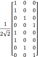
[114bis-R18-MIMO] � Eko (Samsung)
Email discussion on MIMO
- To be used for sharing updates on online/offline schedule, details on what is to be discussed in online/offline sessions, tdoc number of the moderator summary for online session, etc
R1-2309359�������� RRC parameters for Rel-18 NR MIMO�������� Moderator (Samsung)
R1-2308923�������� Maintenance of unified TCI framework extension for multi-TRP������������� Huawei, HiSilicon
R1-2308931�������� Unified TCI framework extension for multi-TRP������������� FUTUREWEI
R1-2308951�������� Discussions on the remaining issue on Unified TCI framework extension for multi-TRP��� New H3C Technologies Co., Ltd.
R1-2308959�������� Remaining Details on Rel-18 Unified TCI for MTRP InterDigital, Inc.
R1-2308973�������� Remaining issues on unified TCI framework extension for multi-TRP������ Spreadtrum Communications
R1-2309013�������� Maintenance on unified TCI framework extension for multi-TRP������������� ZTE
R1-2309060�������� Maintenance on unified TCI framework extension for multi-TRP������������� vivo
R1-2309159�������� Maintenance of unified TCI framework extension for multi-TRP������������� Ericsson
R1-2309163�������� Unified TCI framework extension for multi-TRP/panel����������� LG Electronics
R1-2309208�������� Unified TCI Framework Extension for Multi-TRP����� Intel Corporation
R1-2309231�������� Discussion on unified TCI framework extension for multi-TRP������������� Hyundai Motor Company
R1-2309282�������� Remaining issues on unified TCI framework extension for multi-TRP������ NEC
R1-2309315�������� Maintenance on unified TCI framework for multi-TRP������������� Lenovo
R1-2309360�������� Views on unified TCI extension focusing on m-TRP� Samsung
R1-2309424�������� Remaining issues on unified TCI framework extension for multi-TRP������ xiaomi
R1-2309493�������� Remaining issues on unified TCI framework extension for multi-TRP������ CATT
R1-2309563�������� Remaining issue of unified TCI framework extension for multi-TRP������ OPPO
R1-2309636�������� Discussion on unified TCI framework extension for multi-TRP������������� Fujitsu
R1-2309659�������� Remaining issues on unified TCI framework extension for multi-TRP������ CMCC
R1-2309714�������� Remaining issues of unified TCI framework extension for multi-TRP������ Transsion Holdings
R1-2309763�������� Discussions on unified TCI framework extension for multi-TRP������������� Ruijie Network Co. Ltd
R1-2309784�������� Discussion on unified TCI framework extension for multi-TRP������������� Google
R1-2309802�������� Discussion on unified TCI framework extension for multi-TRP operation������������ TCL
R1-2309820�������� Unified TCI framework extension for multi-TRP������� Apple
R1-2309915�������� Maintenance of unified TCI framework extension for multi-TRP������������� Nokia, Nokia Shanghai Bell
R1-2309933�������� Remaining issues on unified TCI framework extension for multi-TRP������ Panasonic
R1-2309962�������� Maintenance on unified TCI framework extension for multi-TRP������������� Sharp
R1-2309978�������� Remaining issues on unified TCI framework extension for multi-TRP������ MediaTek Inc.
R1-2310022�������� Remaining issues on unified TCI framework extension for multi-TRP������ NTT DOCOMO, INC.
R1-2310127�������� Extension of unified TCI framework for mTRP���������� Qualcomm Incorporated
R1-2310229�������� Multi-TRP enhancements for the unified TCI framework������������� Fraunhofer IIS, Fraunhofer HHI
R1-2310206�������� Moderator summary on extension of unified TCI framework (Round 0)����������� Moderator (MediaTek Inc.)
From Monday session
Agreement
� Proposal 4.5 in R1-2310206 is agreed for the editor�s CR.
Agreement
On unified TCI framework extension, if the scheduling offset between the last symbol of the PDCCH carrying the triggering DCI and the first symbol of AP CSI-RS for BM/CSI is smaller than a threshold for AP CSI-RS reception:
R1-2310207�������� Moderator summary on extension of unified TCI framework (Round 1)����������� Moderator (MediaTek Inc.)
Presented in Tuesday session.
R1-2310455�������� Moderator summary on extension of unified TCI framework (Round 2)����������� Moderator (MediaTek Inc.)
From Wednesday session
Agreement
� Adopt the following text proposal for TS 38.214 V18.0.0 Section 5.1.2.3, 5.1.3.1, 5.1.3.2, 5.1.6.2, and 5.1.6.3
|
5.1.2.3����� Physical resource block (PRB) bundling <Unchanged part is omitted> For a UE configured by the higher layer parameter repetitionScheme set to 'fdmSchemeA' or 'fdmSchemeB', and when the UE not configured with dl-OrJointTCI-StateList is indicated with two TCI states in a codepoint of the DCI field 'Transmission Configuration Indication', or when the UE configured with dl-OrJointTCI-StateList and having two indicated TCI-States is determined to apply both indicated TCI-States to PDSCH, and the UE is indicated with DM-RS port(s) within one CDM group in the DCI field 'Antenna Port(s)', 2 -� If 3 -� If
4 -� The UE is not expected to receive more than two PDSCH transmission layers for each PDSCH transmission occasion. For a UE configured by the higher layer parameter repetitionScheme
set to 'fdmSchemeB', and when the UE not
configured with dl-OrJointTCI-StateList is indicated with two
TCI states in a codepoint of the DCI field 'Transmission
Configuration Indication', or when the UE configured
with dl-OrJointTCI-StateList and having two indicated TCI-States is
determined to apply both indicated TCI-States to PDSCH, and
the UE is indicated with and DM-RS port(s) within one CDM
group in the DCI field 'Antenna Port(s)', each PDSCH transmission
occasion shall follow the Clause 7.3.1 of [4, TS 38.211] with the mapping to
resource elements determined by the assigned PRBs for corresponding TCI
state of the PDSCH transmission occasion, and the UE shall only expect at
most two code blocks per PDSCH transmission occasion when a single
transmission layer is scheduled and a single code block per PDSCH
transmission occasion when two transmission layers are scheduled. For two
PDSCH transmission occasions, the redundancy version to be applied is derived
according to Table 5.1.2.1-2, where |
|
5.1.3.1����� Modulation order and target code rate determination <Unchanged part is omitted> For a UE configured with the higher layer parameter repetitionScheme set to 'fdmSchemeB', and when the UE not configured with dl-OrJointTCI-StateList is indicated with two TCI states in a codepoint of the DCI field 'Transmission Configuration Indication', or when the UE configured with dl-OrJointTCI-StateList and having two indicated TCI-States is determined to apply both indicated TCI-States to PDSCH, and the UE is indicated with and DM-RS port(s) within one CDM group in the DCI field 'Antenna Port(s)', the determined modulation order of PDSCH transmission occasion associated with the first TCI state is applied to the PDSCH transmission occasion associated with the second TCI state. <Unchanged part is omitted> 5.1.3.2����� Transport block size determination <Unchanged part is omitted> For
a UE configured with the higher layer parameter repetitionScheme set
to 'fdmSchemeB', and when
the UE not configured with dl-OrJointTCI-StateList is indicated with two TCI states in a codepoint of
the DCI field 'Transmission Configuration Indication',
or when the UE configured with dl-OrJointTCI-StateList and having two
indicated TCI-States is determined to apply both indicated TCI-States to
PDSCH, and the UE is indicated with DM-RS
port(s) within one CDM group in the DCI field 'Antenna Port(s)', the
TBS determination follows the steps 1-4 with the following modification in
step 1: a
UE determines the total number of REs allocated for PDSCH ( <Unchanged part is omitted> |
|
5.1.6.2����� DM-RS reception procedure <Unchanged part is omitted> When a UE is not indicated with a DCI that DCI field 'Time domain resource assignment' indicating an entry which contains repetitionNumber in PDSCH-TimeDomainResourceAllocation, the UE is not configured with sfnSchemePdsch and it is indicated with two TCI states in a codepoint of the DCI field 'Transmission Configuration Indication' for the UE not configured with dl-OrJointTCI-StateList or determined to apply both indicated TCI-States to PDSCH for the UE configured with dl-OrJointTCI-StateList and having two indicated TCI-States, and it is indicated with DM-RS port(s) within two CDM groups in the DCI field 'Antenna Port(s)', 5 -� the first TCI state corresponds to the CDM group of the first antenna port indicated by the antenna port indication table, and the second TCI state corresponds to the other CDM group. If a UE is configured with higher layer parameter dmrs-FD-OCC-DisabledForRank1-PDSCH and the UE is scheduled with PDSCH with single DM-RS port, the UE may assume that set of orthogonal DM-RS antenna ports from the same CDM group using different set of wf(k') codes are not associated with the transmission of PDSCH to another UE. 5.1.6.3����� PT-RS reception procedure <Unchanged part is omitted> When a UE is not indicated with a DCI that DCI field 'Time domain resource assignment' indicating an entry which contains repetitionNumber in PDSCH-TimeDomainResourceAllocation, and if the UE is configured with the higher layer parameter maxNrofPorts equal to n2, the UE is not configured with sfnSchemePdsch and if the UE not configured with dl-OrJointTCI-StateList is indicated with two TCI states by the codepoints of the DCI field 'Transmission Configuration Indication' or if the UE configured with dl-OrJointTCI-StateList and having two indicated TCI-States is determined to apply both indicated TCI-States to PDSCH, and the UE is indicated with DM-RS port(s) within two CDM groups in the DCI field 'Antenna Port(s)', the UE shall receive two PT-RS ports which are associated to the lowest indexed DM-RS port among the DM-RS ports corresponding to the first/second indicated TCI state, respectively. When a UE configured by the higher layer parameter repetitionScheme set to 'fdmSchemeA' or �'fdmSchemeB', and the UE not configured with dl-OrJointTCI-StateList is indicated with two TCI states in a codepoint of the DCI field 'Transmission Configuration Indication' or the UE configured with dl-OrJointTCI-StateList and having two indicated TCI-States is determined to apply both indicated TCI-States to PDSCH, and the UE is indicated with DM-RS port(s) within one CDM group in the DCI field 'Antenna Port(s)', the UE shall receive a single PT-RS port which is associated with the lowest indexed DM-RS antenna port among the DM-RS antenna ports assigned for the PDSCH, a PT-RS frequency density is determined by the number of PRBs associated to each TCI state, and a PT-RS resource element mapping is associated to the allocated PRBs for each TCI state. |
Agreement
� Adopt the following text proposal for TS 38.214 V18.0.0 Section 5.1.2.1:
|
5.1.2.1����� Resource allocation in time domain <Unchanged part is omitted> When a UE is configured by the higher layer parameter repetitionScheme set to 'tdmSchemeA' and indicated DM-RS port(s) within one CDM group in the DCI field 'Antenna Port(s)', the number of PDSCH transmission occasions is derived by the number of TCI states indicated by the DCI field 'Transmission Configuration Indication' of the scheduling DCI for the UE not configured with dl-OrJointTCI-StateList, or by the number of indicated TCI-States that are determined to apply to PDSCH for the UE configured with dl-OrJointTCI-StateList and having two indicated TCI-States. -����� If two TCI states are indicated by the
DCI field 'Transmission Configuration Indication' for a UE not configured with dl-OrJointTCI-StateList,
or both indicated TCI-States are
determined to apply to PDSCH for a UE configured with dl-OrJointTCI-StateList
and having two indicated TCI-States, the UE is
expected to receive two PDSCH transmission occasions, where the first TCI
state is applied to the first PDSCH transmission occasion and resource
allocation in time domain for the first PDSCH transmission occasion follows
Clause 5.1.2.1. The second TCI state is applied to the second PDSCH
transmission occasion, and the second PDSCH transmission occasion shall have
the same number of symbols as the first PDSCH transmission occasion. If the
UE is configured by the higher layers with a value -����� Otherwise, the UE is expected to receive a single PDSCH transmission occasion, and the resource allocation in the time domain follows Clause 5.1.2.1. When a UE configured by the higher layer parameter PDSCH-config that indicates at least one entry contains repetitionNumber in PDSCH-TimeDomainResourceAllocation, -����� If two TCI states are indicated by the DCI field 'Transmission Configuration Indication' for a UE not configured with dl-OrJointTCI-StateList, or both indicated TCI-States are determined to apply to PDSCH for a UE configured with dl-OrJointTCI-StateList and having two indicated TCI-States, together with the DCI field 'Time domain resource assignment' indicating an entry which contains repetitionNumber in PDSCH-TimeDomainResourceAllocation and DM-RS port(s) within one CDM group in the DCI field 'Antenna Port(s)', the same SLIV is applied for all PDSCH transmission occasions across the repetitionNumber consecutive slots, the first TCI state is applied to the first PDSCH transmission occasion and resource allocation in time domain for the first PDSCH transmission occasion follows Clause 5.1.2.1. ������ When the value indicated by repetitionNumber in PDSCH-TimeDomainResourceAllocation equals to two, the second TCI state is applied to the second PDSCH transmission occasion. When the value indicated by repetitionNumber in PDSCH-TimeDomainResourceAllocation is larger than two, the UE may be further configured to enable cyclicMapping or sequenticalMapping in tciMapping. -����� When cyclicMapping is enabled, the first and second TCI states are applied to the first and second PDSCH transmission occasions, respectively, and the same TCI mapping pattern continues to the remaining PDSCH transmission occasions. -����� When sequenticalMapping is enabled, first TCI state is applied to the first and second PDSCH transmission occasions, and the second TCI state is applied to the third and fourth PDSCH transmission occasions, and the same TCI mapping pattern continues to the remaining PDSCH transmission occasions. The UE may
expect that each PDSCH transmission occasion is limited to two transmission
layers. For
all PDSCH transmission occasions associated with the first TCI
state, the
redundancy version to be applied is derived according to Table 5.1.2.1-2, where Table 5.1.2.1-3: Applied redundancy version for the second TCI state when sequenceOffsetforRV is present
-����� If one TCI state is indicated by the
DCI field 'Transmission Configuration Indication' for
a UE not configured with dl-OrJointTCI-StateList, or one indicated TCI-State
is determined to apply to PDSCH for a UE configured with dl-OrJointTCI-StateList, together
with the DCI field 'Time domain resource assignment' indicating an entry which
contains repetitionNumber in PDSCH-TimeDomainResourceAllocation
and DM-RS port(s) within one CDM group in the DCI field 'Antenna Port(s)',
the same SLIV is applied for all PDSCH transmission occasions across the repetitionNumber
consecutive slots, the first PDSCH transmission occasion follows Clause
5.1.2.1, the same TCI state is applied to all PDSCH transmission occasions.
The UE may expect that each PDSCH transmission occasion is limited to two
transmission layers. For all PDSCH transmission occasions, the
redundancy version to be applied is derived according to Table 5.1.2.1-2, where -����� Otherwise, the UE is expected to receive a single PDSCH transmission occasion, and the resource allocation in the time domain follows Clause 5.1.2.1. <Unchanged part is omitted> |
|||||||||||||||||||||||||||||
Agreement
� Adopt the following text proposal for TS 38.214 V18.0.0 Section 5.1:
|
5.1������������ UE procedure for receiving the physical downlink shared channel <Unchanged part is omitted> When a UE is configured by higher layer parameter repetitionScheme set to one of 'fdmSchemeA', 'fdmSchemeB', 'tdmSchemeA', if the UE not configured with dl-OrJointTCI-StateList is indicated with two TCI states in a codepoint of the DCI field 'Transmission Configuration Indication', or if the UE configured with dl-OrJointTCI-StateList and having two indicated TCI-States is determined to apply both indicated TCI-States to PDSCH, and the UE is indicated with DM-RS port(s) within one CDM group in the DCI field 'Antenna Port(s)'. -����� When -����� When -����� When When
a UE is configured by the higher layer parameter repetitionNumber
in PDSCH-TimeDomainResourceAllocation, the UE not configured with dl-OrJointTCI-StateList
may expect to be indicated with one or two TCI states in a codepoint of the DCI field 'Transmission Configuration
Indication' or the UE configured with dl-OrJointTCI-StateList
-����� When two TCI states are indicated in a DCI with 'Transmission Configuration Indication' field for the UE not configured with dl-OrJointTCI-StateList, or when both indicated TCI-States are determined to apply to PDSCH for the UE configured with dl-OrJointTCI-StateList and having two indicated TCI-States, the UE may expect to receive multiple slot level PDSCH transmission occasions of the same TB with two TCI states used across multiple PDSCH transmission occasions in the repetitionNumber consecutive slots as defined in Clause 5.1.2.1. -����� When
one TCI state is indicated in a DCI with 'Transmission Configuration
Indication' field for the UE not configured with dl-OrJointTCI-StateList, or when one indicated TCI-State is determined to apply to PDSCH for the
UE configured with dl-OrJointTCI-StateList When a UE is not indicated with a DCI that DCI field 'Time domain resource assignment' indicating an entry which contains repetitionNumber in PDSCH-TimeDomainResourceAllocation, and it is indicated with two TCI states in a codepoint of the DCI field 'Transmission Configuration Indication' for the UE not configured with dl-OrJointTCI-StateList, or it is determined to apply both indicated TCI-States to PDSCH for the UE configured with dl-OrJointTCI-StateList and having two indicated TCI-States, and is indicated with DM-RS port(s) within two CDM groups in the DCI field 'Antenna Port(s)' and it is not configured with higher layer parameter sfnSchemePdsch, the UE may expect to receive a single PDSCH where the association between the DM-RS ports and the TCI states are as defined in Clause 5.1.6.2. When a UE is not indicated with a DCI that DCI field 'Time domain resource assignment' indicating an entry which contains repetitionNumber in PDSCH-TimeDomainResourceAllocation, and it is not configured with dl-OrJointTCI-StateList and is indicated with one TCI states in a codepoint of the DCI field 'Transmission Configuration Indication', or it is configured with dl-OrJointTCI-StateList and is determined to apply one indicated TCI-State to PDSCH, the UE procedure for receiving the PDSCH upon detection of a PDCCH follows Clause 5.1. When a UE is configured with higher layer parameter sfnSchemePdsch set to either 'sfnSchemeA' or 'sfnSchemeB' for a DL BWP and -����� if the UE reports its
capability of sfn-SchemeA-DynamicSwitching -����� otherwise,
the UE not configured with dl-OrJointTCI-StateList
is not expected to be indicated with one TCI state per any of TCI codepoint
by MAC CE the UE procedure for receiving the PDSCH upon detection of a PDCCH follows clause 5.1 and the QCL assumption for the PDSCH as defined in clause 5.1.5. When a UE is configured with both sfnSchemePdsch and sfnSchemePdcch, the UE shall expect that sfnSchemePdsch and sfnSchemePdcch are set to the same scheme, either 'sfnSchemeA' or 'sfnSchemeB'. If a UE not configured
with dl-OrJointTCI-StateList is configured with sfnSchemePdcch set to 'sfnSchemeA'
for a DL BWP and activated with two TCI states by MAC CE, and the UE does not
report its capability of sfn-SchemeA-PDCCH-only, the UE is expected to
be configured with sfnSchemePdsch set to 'sfnSchemeA' and
indicated with two TCI states to be applied to PDSCH in a codepoint of the
DCI field 'Transmission Configuration Indication', if the PDSCH is
scheduled by DCI format 1_1/1_2. If a UE configured with dl-OrJointTCI-StateList and having two indicated TCI-States is configured with sfnSchemePdcch set to 'sfnSchemeA' for a DL BWP and signaled by the higher layer parameter [applyIndicatedTCIState] to apply both indicated TCI-States to a PDCCH on a CORESET, and the UE does not report its capability of sfn-SchemeA-PDCCH-only, the UE is expected to be configured with sfnSchemePdsch set to 'sfnSchemeA' and both indicated TCI-States are determined to apply to PDSCH, if the PDSCH is scheduled by DCI format 1_1/1_2 on the PDCCH. If a UE not configured with dl-OrJointTCI-StateList is configured with sfnSchemePdcch set to 'sfnSchemeB' for a DL BWP and activated with two TCI states by MAC CE, the UE is expected to be configured with sfnSchemePdsch set to 'sfnSchemeB' and indicated with two TCI states in a codepoint of the DCI field 'Transmission Configuration Indication'', if the PDSCH is scheduled by DCI format 1_1/1_2. If a UE configured with dl-OrJointTCI-StateList and having two indicated TCI-States is configured with sfnSchemePdcch set to 'sfnSchemeB' for a DL BWP, and signaled by the higher layer parameter [applyIndicatedTCIState] to apply both indicated TCI-States to a PDCCH on a CORESET, the UE is expected to be configured with sfnSchemePdsch set to 'sfnSchemeB' and both indicated TCI-States are determined to apply to PDSCH, if the PDSCH is scheduled by DCI format 1_1/1_2 on the PDCCH. <Unchanged part is omitted> |
R1-2310505�������� Moderator summary on extension of unified TCI framework (Round 3)����������� Moderator (MediaTek Inc.)
From Thursday session
Agreement
On unified TCI framework extension for M-DCI based MTRP, if the scheduling offset between the last symbol of the PDCCH carrying a scheduling DCI and the first symbol of the scheduled PDSCH is smaller than a threshold:
� If the UE doesn�t support the capability of default beam per coresetPoolIndex for M-DCI based MTRP in FR2:
o The UE shall apply the indicated joint/DL TCI state specific to coresetPoolIndex value 0 to the scheduled PDSCH reception
o The UE doesn�t expect to be scheduled with PDSCH with scheduling offset less than a threshold of the PDSCH if scheduled by a CORESET associated with coresetPoolIndex value 1
� Note: If the UE supports the capability of default beam per coresetPoolIndex for M-DCI based MTRP in FR2, UE can use both indicated joint/DL TCI states to buffer the received signal before a threshold.
Agreement
On unified TCI framework extension for S-DCI based MTRP, if twoPHRMode is configured, and two SRS resource sets for CB/NCB and multipanelScheme for SDM/SFN are configured:
� If the UE determines that only one Type 1 PHR is based on an actual PUSCH transmission
o If the actual PUSCH transmission applies only the first indicated joint/UL TCI state, the UE provides the second {power headroom, configured max output power} associated with the second indicated joint/UL TCI state for a reference PUSCH transmission
o If the actual PUSCH transmission applies only the second indicated joint/UL TCI state, the UE provides the first {power headroom, configured max output power} associated with the first indicated joint/UL TCI state for a reference PUSCH transmission
� If the UE determines that both Type 1 PHRs are based on reference PUSCH transmissions, the UE provides the first {power headroom, configured max output power} associated with the first indicated joint/UL TCI state for a reference PUSCH transmission, and the second {power headroom, configured max output power} associated with the second indicated joint/UL TCI state for another reference PUSCH transmission
� FFS: Whether the configured max output power reported in above cases is per UE or per panel or both
�
Down-select
one of the following alternatives to be reported along with the power headroom
for a reference PUSCH transmission:
o
Alt1:
Per-panel configured max output power
o
Alt2:
Per-UE configured max output power
o
Alt3:
Both per-panel configured max output power and per-UE configured max output
power
o
Alt4:
None
R1-2310504�������� Summary of agreed TP for Rel-18 Unified TCI framework extension������������ Moderator (MediaTek Inc.)
R1-2310658�������� Moderator summary on extension of unified TCI framework (Final)�� Moderator (MediaTek Inc.)
R1-2308924�������� Maintenance of TA enhancement for UL M-TRP transmission������������� Huawei, HiSilicon
R1-2308932�������� Enhancements to support two TAs for multi-DCI������������� FUTUREWEI
R1-2308960�������� Remaining Details on Rel-18 Multiple TA Operation InterDigital, Inc.
R1-2308974�������� Remaining issues on two TAs for multi-DCI based multi-TRP������������� Spreadtrum Communications
R1-2309014�������� Maintenance on TA enhancement for multi-DCI�������� ZTE
R1-2309061�������� Maintenance on two TAs for multi-DCI-based multi-TRP operation������������ vivo
R1-2309160�������� Maintenance of two TAs for multi-DCI�������� Ericsson
R1-2309164�������� Two TAs for multi-TRP/panel������� LG Electronics
R1-2309202�������� On two TAs for multi-DCI Intel Corporation
R1-2309283�������� Remaining issues on two TAs for multi-DCI NEC
R1-2309316�������� Remaining issue of two TAs for multi-DCI UL transmission������������� Lenovo
R1-2309361�������� Remaining details on two TAs for m-DCI���� Samsung
R1-2309425�������� Discussion on two TAs for multi-TRP operation�������� xiaomi
R1-2309494�������� Remaining issues on two TAs for UL multi-DCI multi-TRP operation������������ CATT
R1-2309564�������� Remaining issue of two TAs for multi-DCI based multi-TRP operation������������ OPPO
R1-2309660�������� Remaining issues on two TAs for multi-DCI CMCC
R1-2309715�������� Remaining issues of two TAs for multi-DCI based multi-TRP operation������������ Transsion Holdings
R1-2309764�������� Discussions on two TAs for multi-DCI��������� Ruijie Network Co. Ltd
R1-2309785�������� Discussion on two TAs for multi-DCI���������� Google
R1-2309790�������� Discussion on multi-TA Cells for beam failure recovery������������� ASUSTEK
R1-2309821�������� Two TAs for multi-DCI mTRP������� Apple
R1-2309916�������� Maintenance of two TAs for UL multi-DCI multi-TRP operation������������� Nokia, Nokia Shanghai Bell
R1-2309963�������� Maintenance on two TAs for multi-DCI������� Sharp
R1-2310023�������� Remaining issues on two TAs for multi-DCI NTT DOCOMO, INC.
R1-2310128�������� Supporting two TAs for multi-DCI based mTRP�������� Qualcomm Incorporated
R1-2310357�������� Moderator Summary #1 on Two TAs for multi-DCI������������� Moderator (Ericsson)
From Monday session
Agreement
The following working assumption is confirmed.
�For intra-cell multi-DCI based Multi-TRP operation with two TA enhancement, support the case where a PDCCH order sent by TRPX triggers RACH procedure towards either TRPX or TRPY.�
Above confirmation does not change power control for the same TRP PDCCH order.
R1-2310432�������� Moderator Summary #2 on Two TAs for multi-DCI������������� Moderator (Ericsson)
Presented in Tuesday session.
R1-2310554�������� Moderator Summary #3 on Two TAs for multi-DCI������������� Moderator (Ericsson)
From Thursday session
Agreement
For inter-cell multi-DCI based Multi-TRP operation with two TA enhancement, 1 bit is supported for indicating active additionalPCI in the PDCCH order.
� The single bit in the PDCCH order indicates if the PRACH triggering is towards servingCell PCI or active additionalPCI.
Note: This has no impact on whether common or separate field with cell indication in LTM is used.
Agreement
When a UE is configured with both the inter-cell multi-DCI based Multi-TRP operation with two TAs and Rel-18 LTM features,
� separate fields are used to indicate additionalPCI (for inter-cell mTRP) and to indicate cell indicator field (for Rel-18 LTM).
Conclusion
There is no consensus to extend 2TA enhancement to BFD/BFR in Rel-18.
R1-2308925�������� Maintenance of` CSI enhancement for coherent JT and mobility������������� Huawei, HiSilicon
R1-2308961�������� Remaining Details on Rel-18 CSI Enhancements������� InterDigital, Inc.
R1-2308975�������� Remaining issues on CSI enhancement�������� Spreadtrum Communications
R1-2309015�������� Maintenance on CSI enhancement for high/medium UE velocities and CJT ZTE
R1-2309062�������� Maintenance on CSI enhancement� vivo
R1-2309206�������� On CSI enhancements for NR��������� Intel Corporation
R1-2309254�������� On CSI Enhancement������� Google
R1-2309274�������� Remaining issues on CSI enhancement�������� NEC
R1-2309317�������� Discussion of CSI enhancement for high speed UE and coherent JT��������� Lenovo
R1-2309363�������� Views on CSI enhancements���������� Samsung
R1-2309426�������� Maintenance on CSI enhancement for high/medium UE velocities and CJT xiaomi
R1-2309495�������� Maintenance on CSI enhancement� CATT
R1-2309565�������� Remaining issues on CSI enhancement for high/medium UE velocities and coherent JT OPPO
R1-2309637�������� Maintenance on Rel-18 CSI enhancements�� Fujitsu
R1-2309661�������� Remaining issues on CSI enhancement for high/medium UE velocities and� CJT����������� CMCC
R1-2309765�������� Discussions on CSI enhancement��� Ruijie Network Co. Ltd
R1-2309822�������� Views on Rel-18 MIMO CSI enhancement�� Apple
R1-2309917�������� Maintenance of CSI enhancement for high/medium UE velocities and CJT Nokia, Nokia Shanghai Bell
R1-2310024�������� Remaining issues on CSI enhancement�������� NTT DOCOMO, INC.
R1-2310085�������� Remaining issues on CSI for Rel-18 NR MIMO evolution������������� Ericsson
R1-2310129�������� Remaining issues and maintenance on Rel-18 CSI enhancement������������� Qualcomm Incorporated
R1-2310228�������� CSI enhancements for medium UE velocities and coherent JT������������� Fraunhofer IIS, Fraunhofer HHI
R1-2309362�������� Moderator summary on Rel-18 CSI enhancements Moderator (Samsung)
From Monday session
Agreement
For the Rel-18 Type-II codebook refinement for CJT mTRP, clarify, in TS 38.214 section 5.2.1.4.1, that if NZP CSI-RS resource for interference measurement is configured, only one resource is configured in the corresponding NZP-CSI-RS-ResourceSet for interference measurement.
Agreement
For the Rel-18 Type-II codebook refinement for CJT mTRP, with respect to L or , the supported Parameter Combinations is enumerated for each NTRP value (up to 5 for Rel-16-based and 8 for Rel-17-based), rather than enumerating across all NTRP values of 1, 2, 3, and 4 (up to 17 for Rel-16-based and 20 for Rel-17-based).
� Note: in TS38.214, this affects Tables 5.2.2.2.8-1, 5.2.2.2.8-3, 5.2.2.2.9-1, and 5.2.2.2.9-3
Conclusion
For the Rel-18 Type-II codebook refinement for CJT mTRP, there is no consensus on the following:
� Clarifying, in TS38.214 section 5.2.2.2.8), that the RRC parameter n1-n2-codebookSubsetRestriction-CJT-r18 is configured for at least one of the NTRP CSI-RS resources if CBSR is configured.
� Amending, in TS 38.214 section 5.2.2.2.8, the precoder normalization from the sum to the maximum of squared-magnitude across the NTRP CSI-RS resources.
� Regarding the condition on reporting/dropping a CSI report, amending, in TS 38.214 section 5.2.2.5.1, that one CSI-RS transmission occasion is interpreted to include �all� (replacing �one�) of CSI-RS resources in the corresponding CSI-RS Resource Set.
Agreement
For the Rel-18 Type-II codebook refinement for CJT mTRP, regarding the condition on reporting/dropping a CSI report, capture, in TS 38.214 section 5.2.2.5.1, the following condition: �� after the CSI report (re)configuration, serving cell activation, BWP change, or activation of SP-CSI�.
� Further discuss how to reflect cell DTX/DRX as part of the condition under agenda item 8.5
Agreement
For the Type-II codebook refinement for high/medium velocities, add, in TS 38.214 section 5.2.2.5.1, that in addition to �in the CSI reference resource�, CQI (and if configured PMI/RI) calculation should assume �in each of the slot(s) where the CQI in the predicted CSI is associated with as defined in sub-clause 5.2.1.4.2�.
Agreement
For the Type-II codebook refinement for high/medium velocities, clarify, in TS 38.214 section 5.2.1.4.1, that if NZP CSI-RS resource for interference measurement is configured, only one resource is configured in the corresponding NZP-CSI-RS-ResourceSet for interference measurement.
Agreement (further amended with CR coversheet info as shown below in Thursday session)
Regarding the condition on reporting/dropping a CSI report, adopt the following TP in TS 38.214 section 5.2.2.5:
|
For a CSI-ReportConfig
configured with codebookType set to �typeII-Doppler-r18� or
�typeII-Doppler-PortSelection-r18�, the UE reports a CSI report only if
receiving at least one aperiodic or |
Conclusion
For the Type-II codebook refinement for high/medium velocities, in case of TDD, there is no consensus on the following:
� Regarding the condition on reporting/dropping a CSI report, amending, in TS 38.214 section 5.2.2.5.1, that one CSI-RS transmission occasion is interpreted to include �all� (replacing �one�) of CSI-RS resources in the corresponding CSI-RS Resource Set.
Agreement
For the Type-II codebook refinement for high/medium velocities, regarding the condition on reporting/dropping a CSI report, capture, in TS 38.214 section 5.2.2.5.1, the following condition: ��after the CSI report (re)configuration, serving cell activation, BWP change, or activation of SP-CSI�.
� Further discuss how to reflect cell DTX/DRX as part of the condition under agenda item 8.5.
Agreement
For the Rel-18 TRS-based TDCP reporting, regarding interference measurement, interference measurement is not supported (hence neither CSI-IM nor NZP CSI-RS resource for interference measurement can be configured).
� Whether/How to capture the above is up to the editor.
Conclusion
For the Rel-18 TRS-based TDCP reporting, there is no consensus on the following:
�
Reverting a previous
agreement by specifying the TDCP entry value ![]() �as �invalid� and a UE behavior to report this entry value when TDCP
determination accuracy is low.
�as �invalid� and a UE behavior to report this entry value when TDCP
determination accuracy is low.
� Clarifying that UE is not expected to be configured with Y, Dn and/or KTRS value(s), wherein at least two TRS instances separated by Dn symbols/slots are unavailable.
�
Adding, in TS 38.214
section 5.2.1.2, the following UE behaviour: when ![]() , the UE does not expect the CSI-RS Resources of more than one of
the
, the UE does not expect the CSI-RS Resources of more than one of
the ![]() �CSI-RS Resource Sets are configured as QCL source with respect to
�typeA� or �typeD� of any potential PDCCH or PDSCH.
�CSI-RS Resource Sets are configured as QCL source with respect to
�typeA� or �typeD� of any potential PDCCH or PDSCH.
R1-2310390�������� Moderator Summary for Tuesday offline on Rel-18 CSI enhancements����� Moderator (Samsung)
R1-2310389�������� Moderator Summary#2 on Rel-18 CSI enhancements: Round 1����������� Moderator (Samsung)
From Wednesday session
Agreement
For the Rel-18 TRS-based TDCP reporting,
add the following in TS 38.215 on TDCP description: �For frequency range 1 and
2, if receiver diversity is in use by the UE, the reported TDCP amplitude value
shall not be lower than the minimum and no higher than the maximum
measured values across the receiver branches.�
� Note: This is based on RAN4 LS R1-2308807.
Agreement (further amended with CR coversheet info as shown below in Thursday session)
For the Rel-18 Type-II codebook refinement for CJT mTRP, amend, in TS 38.214 section 5.2.2.5.1b, as follows:
�
A UE can assume that the PDSCH signals for ![]() �layers
�layers transmitted on the ![]()
�antenna ports of CSI-RS resource ![]() � would have the same
ratio of EPRE to CSI-RS EPRE for all
CSI-RS resources sj
with j=1,�,N, equal to the powerControlOffset
of the respective CSI-RS resource.
� would have the same
ratio of EPRE to CSI-RS EPRE for all
CSI-RS resources sj
with j=1,�,N, equal to the powerControlOffset
of the respective CSI-RS resource.
Agreement
For the Type-II codebook refinement for high/medium velocities, regarding CPU allocation, remove Y=2/3 (previously agreed) and add the support for OCPU=8 for K=12 for AP-CSIRS.
R1-2310445�������� Moderator Summary for Wednesday offline on Rel-18 CSI enhancements����� Moderator (Samsung)
R1-2310444�������� Moderator Summary#3 on Rel-18 CSI enhancements: Round 2����������� Moderator (Samsung)
From Thursday session
Agreement
Adopt the following TP in TS 38.214 section 5.2.2.5 v18.0.0:
� Reason for change: Since one NZP CSI-RS for interference measurement and/or one CSI-IM resource can be configured for a CSI-ReportConfig configured with codebookType set to 'typeII-CJT-r18' or 'typeII-CJT-PortSelection-r18' or 'typeII-Doppler-r18' or 'typeII-Doppler-PortSelection-r18', NZP-IMR should also be considered for the UE behaviors in dropping or reporting CSI report for 'typeII-Doppler-r18' or 'typeII-Doppler-PortSelection-r18', just like the legacy behaviors.
� Summary of change: Added the case where IMR (NZP CSI-RS for IM and/or CSI-IM) is configured as a condition for CSI reporting/dropping
� Consequences if not approved: CSI dropping/reporting behavior is incomplete
|
5.2.2.5����� CSI reference resource definition <Unchanged text is omitted> For a CSI-ReportConfig
configured with codebookType set to �typeII-Doppler-r18� or
�typeII-Doppler-PortSelection-r18�, the UE reports a CSI report only if
receiving at least one aperiodic or < Unchanged parts are omitted > |
Agreement
Adopt the following TP in TS 38.214 section 5.2.2.5.1b v18.0.0:
� Reason for change: The clause �transmitted on P antenna ports of CSI-RS resource sj� may suggest that PDSCH EPRE is assumed per TRP (rather than across all TRPs � which is the case for CJT) for CQI calculation
� Summary of change: Removed �transmitted on P antenna ports of CSI-RS resource sj�
� Consequences if not approved: PDSCH EPRE assumption for CQI calculation when Rel-18 Type-II CJT codebook is used can be misinterpreted
|
5.2.2.5.1b UE assumptions for CQI/PMI/RI calculation for CJT <Unchanged text is omitted> -
a UE can assume that
the PDSCH signals for < Unchanged parts are omitted > |
Agreement
For the Rel-18 TRS-based TDCP reporting, the UE reports a CSI report only if receiving at least one CSI-RS transmission occasion for each CSI-RS resource for KTRS CSI-RS resource sets configured for TDCP reporting no later than CSI reference resource, otherwise drops the report.
� This includes the cases of CSI report (re)configuration, serving cell activation, BWP change.
o FFS (RAN1#115): Whether DRX configuration needs to be included as a case.
R1-2308926�������� Maintenance of DMRS enhancement in Rel.18���������� Huawei, HiSilicon
R1-2308962�������� Remaining Details on Rel-18 DMRS Enhancements�� InterDigital, Inc.
R1-2308976�������� Remaining issues on increased number of orthogonal DMRS ports������������� Spreadtrum Communications
R1-2309016�������� Maintenance on DMRS enhancement for UL/DL MU-MIMO and 8 Tx UL SU-MIMO���������� ZTE, China Telecom
R1-2309063�������� Maintenance on DMRS enhancements��������� vivo
R1-2309211�������� On increased number of orthogonal DMRS ports for MU-MIMO and 8 Tx UL SU-MIMO��� Ericsson
R1-2309255�������� On DMRS Enhancement�� Google
R1-2309275�������� Remaining issues on increased number of orthogonal DMRS ports������������� NEC
R1-2309318�������� Maintenance on increased number of orthogonal� DMRS ports������������� Lenovo
R1-2309364�������� Views on DMRS enhancements����� Samsung
R1-2309427�������� Discussion on the remaining issues about DMRS enhancement������������� xiaomi
R1-2309496�������� Remaining issues on DL and UL DMRS enhancement������������� CATT
R1-2309566�������� Remaining issues on DMRS enhancement for Rel-18 MIMO������������� OPPO
R1-2309638�������� Discussion on remaining issues of PTRS for 8Tx UL transmission������������� Fujitsu
R1-2309662�������� Remaining issues on increased number of orthogonal DMRS ports������������� CMCC
R1-2309766�������� Discussions on increased number of orthogonal DMRS ports������������� Ruijie Network Co. Ltd
R1-2309823�������� Views on remaining issues for DMRS enhancement�� Apple
R1-2309918�������� Maintenance of Rel-18 UL and DL DMRS Enhancements������������� Nokia, Nokia Shanghai Bell
R1-2309964�������� Maintenance on increased number of orthogonal DMRS ports������������� Sharp
R1-2310025�������� Remaining issues on DMRS enhancements�� NTT DOCOMO, INC.
R1-2310130�������� Design for increased number of orthogonal DMRS ports������������� Qualcomm Incorporated
R1-2310278�������� FL summary on DMRS#1������������ Moderator (NTT DOCOMO)
From Monday session
Agreement
The following TPs in R1-2310278 are agreed for the editor�s CR.
� FL Proposal 2.2A
� FL Proposal 2.2B
� FL Proposal 2.3B
Agreement
Introduce a separate UE capability to report the orphan RE capability (i.e. UE can receive PDSCH without the scheduling restriction for FD-OCC length 4 in Rel.18 eType 1 DMRS) for PDSCH with fdmSchemeA or fdmSchemeB.
Conclusion
DCI formats 1_1/1_2/0_1/0_2 and other DCI formats (except for DCI format 0_0/1_0), which are specified as equally applied as at least one of DCI formats 1_1/1_2/0_1/0_2, can indicate Rel.18 DMRS ports.
Agreement
Clarify in TS 38.214 that for partial-coherent and non-coherent codebook-based 8Tx UL transmission, when the UE is configured with 2 PTRS ports, PUSCH antenna port 1000, 1001, 1004 and 1005 share PTRS port 0, and PUSCH antenna port 1002, 1003, 1006 and 1007 share PTRS port 1.
� Adopt the following TP for TS 38.214.
|
6.2.3.1����� UE PT-RS transmission procedure when transform precoding is not enabled *** Unchanged parts are omitted *** For partial-coherent and non-coherent codebook-based UL transmission, the actual number of UL PT-RS port(s) is determined based on TPMI(s) and/or number of layers which are indicated by 'Precoding information and number of layers' field(s) in DCI format 0_1 and DCI format 0_2 or configured by higher layer parameter precodingAndNumberOfLayers: -����� if the UE is configured with the higher layer parameter maxNrofPorts in PTRS-UplinkConfig set to 'n2', the actual UL PT-RS port(s) and the associated transmission layer(s) are derived from indicated TPMI(s) as: -����� For PUSCH transmission with 2 or 4 ports, PUSCH antenna port 1000 and 1002 in indicated TPMI(s) share PT-RS port 0, and PUSCH antenna port 1001 and 1003 in indicated TPMI(s) share PT-RS port 1. -����� UL PT-RS port 0 is associated with the UL layer 'x' of layers which are transmitted with PUSCH antenna port 1000 and PUSCH antenna port 1002 in indicated TPMI(s), and UL PT-RS port 1 is associated with the UL layer 'y' of layers which are transmitted with PUSCH antenna port 1001 and PUSCH antenna port 1003 in indicated TPMI(s), where 'x' and/or 'y' are given by DCI parameter 'PTRS-DMRS association' as shown in DCI format 0_1 and DCI format 0_2 described in Clause 7.3.1 of [5, TS38.212]. -����� For PUSCH transmission with 8 ports, PUSCH antenna port 1000, 1001, 1004 and 1005 in indicated TPMI(s) share PT-RS port 0, and PUSCH antenna port 1002, 1003, 1006 and 1007 in indicated TPMI(s) share PT-RS port 1. - UL PT-RS port 0 is associated with the UL layer 'x' of layers which are transmitted with one or more of PUSCH antenna port 1000, 1001, 1004 and 1005 in indicated TPMI(s), and UL PT-RS port 1 is associated with the UL layer 'y' of layers which are transmitted with one or more of PUSCH antenna port 1002, 1003, 1006 and 1007 in indicated TPMI(s), where 'x' and/or 'y' are given by DCI parameter 'PTRS-DMRS association' as shown in DCI format 0_1 and DCI format 0_2 described in Clause 7.3.1 of [5, TS38.212]. If a UE is scheduled with two codewords, -����� if the UE is configured with the higher layer parameter maxNrofPorts in PTRS-UplinkConfig set to 'n1', the PT-RS port is associated with the one of DM-RS ports indicated by DCI field PTRS-DMRS association for the codeword with the higher MCS. If the MCS indices of the two codewords are the same, the PT-RS antenna port is associated with codeword 0. When a codeword is scheduled to transmit PUSCH for retransmission, the MCS for determining PT-RS association to codeword is obtained from the DCI for the same transport block in the initial transmission. -����� if
the UE is configured with the higher layer parameter maxNrofPorts in PTRS-UplinkConfig
set to 'n2', each PT-RS port is associated with the one of DM-RS ports indicated by DCI field �PTRS-DMRS
association�. *** Unchanged parts are omitted *** |
Agreement
Support to apply Rel-16 low PAPR RS onto Rel-18 enhanced DMRS types (i.e., different DMRS sequence can be applied to DMRS ports included in different CDM group).
� Note: It is up to editors whether/how to specify the above.
R1-2310279�������� FL summary on DMRS#2������������ Moderator (NTT DOCOMO)
From Wednesday session
Agreement
Adopt the following TP for TS 38.214 v18.0.0.
� Reason for change: The text in current TS 38.214 v18.0.0 clause 6.2.2 describes UE behaviour of DMRS configuration type of MsgA PUSCH with [ ]. However, based on TS38.211 v18.0.0, it is clear that Rel.15 Type1 DMRS is applied to MsgA PUSCH. Hence, there is no need to specify it in TS28.214.
� Summary of change: Delete texts in [ ].
� Consequences if not approved: The behaviour of MsgA PUSCH DMRS type is not correct.
|
6.2.2�������� UE DM-RS transmission procedure *** Unchanged parts are omitted ***
*** Unchanged parts are omitted *** |
Agreement
Adopt the following text proposal in TS38.214 v18.0.0.
� Reason for change: The text in current TS 38.214 v18.0.0 clause 5.1.6.2 describes the scheduling restriction if UE does not support orphan RE capability for eType1 DMRS. However, UE behaviour of the scheduling restriction for M-TRP FDM 2a/2b is not captured.
� Summary of change: Specify the scheduling restriction, if UE does not support orphan RE capability for eType1 DMRS, for M-TRP FDM 2a/2b.
� Consequences if not approved: The scheduling restriction, if UE does not support orphan RE capability for eType1 DMRS, for M-TRP FDM 2a/2b is not correct.
|
5.1.6.2����� DM-RS reception procedure < Unchanged parts are omitted >
For DM-RS configuration enhanced type 1, - if a UE is configured with the higher layer parameter repetitionScheme set to 'fdmSchemeA' or �fdmSchemeB�, and is indicated with two TCI states in a codepoint of the DCI field 'Transmission Configuration Indication' and DM-RS port(s) within one CDM group in the DCI field 'Antenna Port(s)', - if a UE is not indicating UE capability of [noSchedulingRestrictionForFDMSchemes-r18], the UE shall assume that the number of consecutively scheduled PRBs for PDSCH for each TCI-state is even, and the offset of the scheduled PRB from common resource block 0 for PDSCH for each TCI-state is even number. - otherwise, - if the UE is not indicating UE capability of [noSchedulingRestriction-r18], the UE shall assume the number of consecutively scheduled PRBs for PDSCH is even, and the offset of the scheduled PRB for PDSCH from common resource block 0 is even number. < Unchanged parts are omitted > |
Agreement
Adopt the following TP for TS 38.214 v18.0.0.
� Reason for change: The text in current TS 38.214 v18.0.0 clause 6.2.3.1 describes PTRS association for 2-port PTRS for two codeword case. However, the same UE behabiour is already specified in other part in clause 6.2.3.1 in TS 38.214 v18.0.0.
� Summary of change: Remove the duplicated text.
� Consequences if not approved: The same UE behaviour is specified in two parts in clause 6.2.3.1 in TS 38.214 v18.0.0, and it makes difficult to understand the spec.
|
6.2.3.1����� UE PT-RS transmission procedure when transform precoding is not enabled < Unchanged parts are omitted > If a UE is scheduled with two codewords, -����� if the UE is configured with the higher layer parameter maxNrofPorts in PTRS-UplinkConfig set to 'n1', the PT-RS port is associated with the one of DM-RS ports indicated by DCI field PTRS-DMRS association for the codeword with the higher MCS. If the MCS indices of the two codewords are the same, the PT-RS antenna port is associated with codeword 0. When a codeword is scheduled to transmit PUSCH for retransmission, the MCS for determining PT-RS association to codeword is obtained from the DCI for the same transport block in the initial transmission.
< Unchanged parts are omitted > |
Agreement
Adopt the following text proposal in TS38.214 v18.0.0.
� Reason for change: The scheduling restriction of orphan RE or eType1 is specified in current TS 38.214 v18.0.0 clause 5.1.6.2. However, the current scheduling restriction cannot ensure orthogonality because the PRBs not available for PDSCH are variable (e.g. PRBs not available for PDSCH declared by RateMatchPattern are configured with 1RB granularity and a symbol level bitmap, leading to the second restriction can�t avoid some orphan RE cases caused by PDSCH rate matching).
� Summary of change: Clarify the offset of the scheduling restriction is the offset of each set of consecutively scheduled PRBs.
� Consequences if not approved: Rel-18 eType 1 DMRS ports cannot be orthogonal for scheduled in MU-MIMO scenario for some cases.
|
5.1.6.2����� DM-RS reception procedure < Unchanged parts are omitted > For DM-RS configuration enhanced type 1, when UE is not
indicating UE capability of [noSchedulingRestriction-r18], the UE
shall assume the number of consecutively scheduled PRBs are even, and the
offset of < Unchanged parts are omitted > |
Agreement
Introduce a UE feature group to indicate the whether/how to support Rel-18 DMRS and PDSCH processing capability 2 simultaneously
Conclusion
Agreement
For the antenna ports indication in Rel.18 eType2 DMRS ports with maxLength = 1 for PUSCH for rank 1-4 in RAN1#114 agreement,
� Remove all remaining rows with [ ].
Agreement
For the antenna ports indication in Rel.18 eType2 DMRS ports with maxLength = 2 for PUSCH for rank 1-4 in RAN1#114 agreement,
� Remove all remaining rows with [ ].
R1-2310280�������� FL summary on DMRS#3������������ Moderator (NTT DOCOMO)
From Thursday session
Agreement
For the antenna ports indication in Rel.18 eType1 DMRS ports with maxLength = 2 for PUSCH for rank 1-4 in RAN1#114 agreement, additionally support/remove the following rows:
� For rank 2 table: support row 21-29, remove row 13, 18, 19.
� For rank 3 table: support row 3-5 and row 11-14 with following modification of row 3, and remove row 9,10.
� For rank 4 table: support row 4, row 7, row 11-16, with following modification of row 7
Table 7.3.1.1.2-48: Antenna port(s), transform precoder is disabled, dmrs-Type=eType1, maxLength=2, rank = 3
|
Value |
Number of DMRS CDM group(s) without data |
DMRS port(s) |
Number of front-load symbols |
|
|
2 |
9-11 |
1 |
Table 7.3.1.1.2-49: Antenna port(s), transform precoder is disabled, dmrs-Type=eType1, maxLength=2, rank = 4
|
Value |
Number of DMRS CDM group(s) without data |
DMRS port(s) |
Number of front-load symbols |
|
|
2 |
1,3,5,7 |
2 |
Conclusion
For the antenna ports indication in Rel.18 eType1 DMRS ports with maxLength = 1 for PUSCH for rank 5-8, no more DMRS ports combinations are supported in Rel.18.
Conclusion
For the antenna ports indication in Rel.18 eType1 DMRS ports with maxLength = 2 for PUSCH for rank 5-8, no more DMRS ports combinations are supported in Rel.18.
Conclusion
For the antenna ports indication in Rel.18 eType2 DMRS ports with maxLength = 1 for PUSCH for rank 5-8, no more DMRS ports combinations are supported in Rel.18.
Conclusion
For the antenna ports indication in Rel.18 eType2 DMRS ports with maxLength = 2 for PUSCH for rank 5-8, no more DMRS ports combinations are supported in Rel.18.
Agreement
When the UE is configured with the higher layer parameter enhanced-dmrs-Type_r18, the UE does not expect to be configured with dmrs-FD-OCC-DisabledForRank1-PDSCH.
Adopt the following text proposal in TS38.214 v18.0.0.
� Reason for change: The text of OCC disabling in current TS 38.214 v18.0.0 clause 5.1.6.2 is applicable irrespective of configuration of enhanced-dmrs-Type_r18. However, it reduces MU capacity, which is not aligned with purpose of Rel.18 DMRS ports.
� Summary of change: The text of OCC disabling is not applicable if UE is configured with enhanced-dmrs-Type_r18.
� Consequence if not approved: UE behaviour when OCC disabling is configured is not correct for Rel.18 DMRS.
|
5.1.6.2����� DM-RS reception procedure < Unchanged parts are omitted > If a UE is configured with higher layer parameter dmrs-FD-OCC-DisabledForRank1-PDSCH and the UE is scheduled with PDSCH with single DM-RS port, the UE may assume that set of orthogonal DM-RS antenna ports from the same CDM group using different set of wf(k') codes are not associated with the transmission of PDSCH to another UE. If a UE is configured with higher layer parameter enhanced-dmrs-Type_r18, the UE does not expect to be configured with dmrs-FD-OCC-DisabledForRank1-PDSCH. < Unchanged parts are omitted > |
Conclusion
For UL 8Tx transmission, there is no consensus to reuse the reserved field in antenna port field for other purposes.
R1-2310466�������� Additional information of text proposals for R18 DMRS������������� Moderator (NTT DOCOMO)
R1-2308927�������� Maintenance of SRS enhancement for TDD CJT and UL 8Tx operation in Rel-18����������� Huawei, HiSilicon
R1-2308933�������� SRS enhancements for TDD CJT and 8TX operation������������� FUTUREWEI
R1-2308963�������� Remaining Details on Rel-18 SRS Enhancements������ InterDigital, Inc.
R1-2308977�������� Remaining issues on SRS enhancement targeting TDD CJT and 8 TX operation������ Spreadtrum Communications
R1-2309017�������� Maintenance on SRS enhancement targeting TDD CJT and 8 TX operation������������ ZTE
R1-2309064�������� Maintenance on SRS enhancements vivo
R1-2309165�������� SRS enhancement targeting TDD CJT and 8 TX operation������ LG Electronics
R1-2309252�������� Remaining issues for SRS enhancements targeting TDD CJT and 8 TX operation��� Ericsson
R1-2309256�������� On SRS Enhancement������ Google
R1-2309276�������� Remaining issues on SRS enhancement������� NEC
R1-2309319�������� Maintenance on SRS enhancement Lenovo
R1-2309365�������� Views on SRS enhancements��������� Samsung
R1-2309428�������� Maintenance on SRS enhancements xiaomi
R1-2309497�������� Maintenance on SRS enhancement CATT
R1-2309567�������� Remaining issues on SRS enhancement targeting TDD CJT and 8 TX operation������ OPPO
R1-2309663�������� Remaining issues on SRS enhancement targeting TDD CJT and 8 TX operation������ CMCC
R1-2309767�������� Discussions on SRS enhancement targeting TDD CJT and 8 TX operation������������ Ruijie Network Co. Ltd
R1-2309824�������� Views on Rel-18 MIMO SRS enhancement� Apple
R1-2309919�������� Maintenance of SRS enhancement for TDD CJT and 8Tx operation������������ Nokia, Nokia Shanghai Bell
R1-2309965�������� Maintenance on SRS enhancement targeting TDD CJT and 8 TX operation������������ Sharp
R1-2310026�������� Remaining issues on SRS enhancement������� NTT DOCOMO, INC.
R1-2310131�������� SRS enhancement for TDD CJT and 8 Tx operation�� Qualcomm Incorporated
R1-2310223�������� Remaining issues on SRS enhancement targeting TDD CJT and 8 TX operation������ KDDI Corporation
R1-2310330�������� FL Summary #1 on SRS enhancements���� Moderator (FUTUREWEI)
From Monday session
Agreement
� Adopt the text proposal for TS38.211 on cyclic shift / comb offset hopping ID notation:
-------------- Start of TP --------------
6.4.1.4.2�� Sequence generation
<Unchanged text is omitted>
The pseudo-random
sequence ![]() �is defined
by clause 5.2.1 and shall be initialized with
�is defined
by clause 5.2.1 and shall be initialized with ![]() �at the
beginning of each radio frame for which
�at the
beginning of each radio frame for which ![]() , where the
cyclic-shift hopping identity
, where the
cyclic-shift hopping identity ![]() �is contained
in the higher-layer parameter cyclicShiftHopping.
�is contained
in the higher-layer parameter cyclicShiftHopping.
<Unchanged text is omitted>
6.4.1.4.3�� Mapping to physical resources
<Unchanged text is omitted>
The pseudo-random
sequence ![]() �is defined
by clause 5.2.1 and shall be initialized with
�is defined
by clause 5.2.1 and shall be initialized with ![]() �at the
beginning of each radio frame for which
�at the
beginning of each radio frame for which ![]() , where the comb
hopping identity
, where the comb
hopping identity ![]() �is contained
in the higher-layer parameter combOffsetHopping.
�is contained
in the higher-layer parameter combOffsetHopping.
<Unchanged text is omitted>
-------------- End of TP --------------
Agreement
� Adopt the text proposal for TS38.211 on cyclic shift / comb offset hopping subset entry indexing:
-------------- Start of TP --------------
6.4.1.4.2�� Sequence generation
<Unchanged text is omitted>
where ![]() �and
�and ![]() is the
is the ![]() th entry and
the cardinality of the set
th entry and
the cardinality of the set
![]()
respectively, where ![]() �is given by
the higher-layer parameter cyclicShiftHoppingSubset if configured,
otherwise
�is given by
the higher-layer parameter cyclicShiftHoppingSubset if configured,
otherwise ![]() .
.
<Unchanged text is omitted>
6.4.1.4.3�� Mapping to physical resources
<Unchanged text is omitted>
where ![]() �and
�and ![]() is the
is the ![]() th entry and the
cardinality of the set
th entry and the
cardinality of the set
![]() respectively,
where
respectively,
where ![]() �is given by
the higher-layer parameter combOffsetHoppingSubset if
configured, otherwise
�is given by
the higher-layer parameter combOffsetHoppingSubset if
configured, otherwise ![]() .
.
<Unchanged text is omitted>
-------------- End of TP --------------
Agreement
� Adopt the text proposal for TS38.211 on cyclic shift / comb offset hopping subset bitmap:
-------------- Start of TP --------------
6.4.1.4.2�� Sequence generation
<Unchanged text is omitted>
where ![]() �and
�and ![]() is the (
is the (![]() +1)th entry and
the cardinality of the set
+1)th entry and
the cardinality of the set
![]()
respectively, where ![]() �is given by
the higher-layer parameter cyclicShiftHoppingSubset if configured,
otherwise
�is given by
the higher-layer parameter cyclicShiftHoppingSubset if configured,
otherwise ![]() . The higher-layer parameter [cyclicShiftHoppingSubset]
includes a bitmap of
. The higher-layer parameter [cyclicShiftHoppingSubset]
includes a bitmap of ![]() �bits
with
�bits
with ![]() �bits
being set, where the (n+1)th bit being set to 1
corresponds to
�bits
being set, where the (n+1)th bit being set to 1
corresponds to ![]() �
�
<Unchanged text is omitted>
6.4.1.4.3�� Mapping to physical resources
<Unchanged text is omitted>
where ![]() �and
�and ![]() is the (
is the (![]() +1)th entry and
the cardinality of the set
+1)th entry and
the cardinality of the set
![]() respectively,
where
respectively,
where ![]() �is given by
the higher-layer parameter combOffsetHoppingSubset if
configured, otherwise
�is given by
the higher-layer parameter combOffsetHoppingSubset if
configured, otherwise ![]() . The
higher-layer parameter [combOffsetHoppingSubset] includes a bitmap of
. The
higher-layer parameter [combOffsetHoppingSubset] includes a bitmap of ![]() �bits
with
�bits
with ![]() �bits
being set, where the (n+1)th bit being set to 1 corresponds
to
�bits
being set, where the (n+1)th bit being set to 1 corresponds
to ![]()
<Unchanged text is omitted>
-------------- End of TP --------------
R1-2310331�������� FL Summary #2 on SRS enhancements���� Moderator (FUTUREWEI)
From Wednesday session
Agreement
SRS comb offset hopping / cyclic shift hopping can be configured for a SRS resource in a SRS resource set with usage �codebook�.
� SRS comb offset hopping / cyclic shift hopping are not supported for a SRS resource in a SRS resource set with usage �nonCodebook� or �beamManagement�.
Agreement
� Adopt the text proposal for TS38.214 on cyclic shift hopping subset and finer granularity configuration:
-------------- Start of TP --------------
6.2.1�������� UE sounding procedure
<Unchanged text is omitted>
-����� Cyclic
shift, as defined by the higher layer parameter cyclicShift-n2, cyclicShift-n4,
or cyclicShift-n8 for transmission comb value 2, 4 or 8, and described in
clause 6.4.1.4 of [4, TS 38.211]. When cyclic shift hopping is configured by
the higher layer parameter [cyclicShiftHopping] for an SRS resource in
an SRS resource set with the usage configured as �antennaSwitching�,
subject to UE capabilities, cyclic shift is updated at every symbol as
described in [clause 6,4,1,4 of [4, TS 38.211]]. For the cyclic shift hopping,
a UE can be configured with a subset of cyclic shifts by the higher layer
parameter [cyclicShiftHoppingSubset], where the cyclic shift hopping is
performed only across the cyclic shifts configured in the subset. For the cyclic shift hopping, a UE can be configured with
finer hopping granularity of ![]() �by
the higher layer parameter [hoppingFinerGranularity]. The UE is not expecting that [hoppingFinerGranularity]
is configured when [cyclicShiftHoppingSubset] is configured
for an SRS resource. The UE is not expecting that the cyclic shift hopping and
the higher layer parameter [tdm] are configured simultaneously for an SRS resource.
�by
the higher layer parameter [hoppingFinerGranularity]. The UE is not expecting that [hoppingFinerGranularity]
is configured when [cyclicShiftHoppingSubset] is configured
for an SRS resource. The UE is not expecting that the cyclic shift hopping and
the higher layer parameter [tdm] are configured simultaneously for an SRS resource.
<Unchanged text is omitted>
-------------- End of TP --------------
Agreement
� Adopt the text proposal for TS38.211 on cyclic shift hopping finer granularity:
-------------- Start of TP --------------
6.4.1.4.2�� Sequence generation
<Unchanged text is omitted>
If
the higher-layer parameter hoppingFinerGranularity is configured and the higher-layer parameter cyclicShiftHoppingSubset
is not configured, ![]() , otherwise
, otherwise ![]() .
.
<Unchanged text is omitted>
-------------- End of TP --------------
Agreement
� Adopt the text proposal for TS38.214 on the frequency hopping behavior when TDM or comb offset hopping is configured:
-------------- Start of TP --------------
6.2.1�������� UE SRS frequency hopping procedure
If for a SRS resource, the higher-layer parameter [tdm] is configured or higher-layer parameter [combOffsetHopping] is configured, the corresponding UE SRS frequency hopping procedure is specified in clause 6.4.1.4.3 of [4, TS 38.211]. If for a SRS resource, the higher-layer parameter [tdm] is not configured and higher-layer parameter [combOffsetHopping] is not configured, the UE SRS frequency hopping procedure is specified in clause 6.4.1.4.3 of [4, TS 38.211] and this clause.
<Unchanged text is omitted>
-------------- End of TP --------------
Agreement
� Adopt the text proposal for TS38.214 on allowing 2 SP SRS resource sets for 8T8R per UE capability:
-------------- Start of TP --------------
6.2.1.2����� UE sounding procedure for DL CSI acquisition
<Unchanged text is omitted>
-����� For 1T=1R, or
2T=2R, 4T=4R or 8T=8R, up to two SRS resource sets
each with one SRS resource can be configured, where the number of SRS ports for
each resource is equal to 1, 2, 4 or 8 if the UE is
not indicating srs-AntennaSwitching2SP-1Periodic.
Two SRS resource sets configured with resourceType in SRS-ResourceSet
set to 'semi-persistent' and one SRS resource set configured with resourceType
in SRS-ResourceSet set to 'periodic' can be configured and the
two SRS resource sets configured with 'semi-persistent' are not
activated at the same time, or up to two SRS resource sets can be configured,
if the UE is indicating srs-AntennaSwitching2SP-1Periodic or [srs-AntennaSwitching2SP-1Periodic8T8R], where each SRS resource set has one SRS resource, the number
of SRS ports for each resource is equal to 1, 2, 4[,
or 8] or
<Unchanged text is omitted>
-------------- End of TP --------------
R1-2310332�������� FL Summary #3 on SRS enhancements���� Moderator (FUTUREWEI)
From Thursday session
Agreement
� Adopt the text proposal for TS38.214 on removing the limitation of no more than one SRS resource set to be triggered/configured:
-------------- Start of TP --------------
6.2.1.2�������������� UE sounding procedure for DL CSI acquisition
<Unchanged text is omitted>
For 1T2R, 1T4R, 2T4R,
1T6R, 1T8R, 2T6R, 2T8R, or 4T8R, or 8T8R, the UE
shall not expect to be configured or triggered with more than one SRS resource
set with higher layer parameter usage set as 'antennaSwitching' in the
same slot. For 1T=1R, 2T=2R 4T=4R, or 8T=8R, the UE shall not expect to be
configured or triggered with more than one SRS resource set with higher layer
parameter usage set as 'antennaSwitching' in the same symbol.
<Unchanged text is omitted>
-------------- End of TP --------------
Conclusion
For an 8-port SRS resource in a SRS resource set with usage
�codebook� / �antennaSwitching� and with TDM
factor s = 2, the 8 ports being fully/partially
coherent, when the s subsets of ports
are mapped onto m ≥ 2 OFDM symbols in a slot according to the pattern
{{1, 2, �, s}, �, {1, 2, �, s}} (totally m/s groups of {1, 2, �, s}), and when
the SRS transmission on a subset of the s OFDM symbols within a group of {1, 2,
�, s} is dropped, the UE still transmits the SRS on the
rest of OFDM symbols within the group of {1, 2, �, s}.
No additional RAN1 spec change will be introduced to support this feature.
Friday session
R1-2310644�������� Draft LS on coherence between PUSCH and 8-ports SRS with partial dropping Moderator (Qualcomm)
Decision: The draft LS is endorsed. Final version is approved in R1-2310645.
R1-2308928�������� Maintenance of UL precoding indication for multi-panel transmission������� Huawei, HiSilicon
R1-2308952�������� Discussions on the remaining issue on UL precoding indication for multi-panel transmission����������� New H3C Technologies Co., Ltd.
R1-2308964�������� Remaining Details on Rel-18 MPUE Uplink Transmission������������� InterDigital, Inc.
R1-2308978�������� Remaining issues on UL precoding indication for multi-panel transmission������� Spreadtrum Communications
R1-2309018�������� Maintenance on UL precoding indication for multi-panel transmission������� ZTE
R1-2309065�������� Maintenance on UL precoding indication for multi-panel transmission������� vivo
R1-2309203�������� UL precoding indication for multi-panel transmission Intel Corporation
R1-2309253�������� Remaining issues for UL precoding indication for multi-panel transmission������� Ericsson
R1-2309257�������� On Simultaneous Multi-Panel Transmission Google
R1-2309284�������� Remaining issues on UL precoding indication for multi-panel transmission������� NEC
R1-2309320�������� Maintenance on UL precoding indication for multi-panel transmission������� Lenovo
R1-2309366�������� Views on UL precoding indication for STxMP����������� Samsung
R1-2309429�������� Maintenance on multi-panel uplink transmission������� xiaomi
R1-2309498�������� Discussion of remaining issues on UL precoding indication for multi-panel transmission�� CATT
R1-2309568�������� Remaining issues of UL precoding indication for multi-panel transmission������� OPPO
R1-2309639�������� Correction on PTRS-DMRS association for configured grant Type 1 PUSCH������������ Fujitsu
R1-2309664�������� Remaining issues on UL precoding indication for multi-panel transmission������� CMCC
R1-2309716�������� Remaining issues of UL precoding indication for multi-panel transmission������� Transsion Holdings
R1-2309768�������� Discussions on UL precoding indication for multi-panel transmission������� Ruijie Network Co. Ltd
R1-2309825�������� Remaining issues on multi-panel simultaneous transmissions������������� Apple
R1-2310027�������� Remaining issues on multi-panel transmission����������� NTT DOCOMO, INC.
R1-2310068�������� Maintenance on UL multi-panel transmission������������ Sharp
R1-2310132�������� Simultaneous multi-panel transmission�������� Qualcomm Incorporated
R1-2310281�������� Summary #1 on Rel-18 STxMP��� Moderator (OPPO)
From Monday session
Agreement
For single TRP operation, when single-DCI STxMP SDM or SFN is configured and two SRS resource sets for CB/NCB are configured:
� If one Type-1 CG PUSCH RRC configuration contains only one SRI field and/or one TPMI field, the PUSCH transmission of this CG PUSCH is associated with the first SRS resource set if the first indicated TCI state is applied, and the PUSCH transmission of this CG PUSCH is associated with the second SRS resource set if the second indicated TCI state is applied.
Agreement
Adopt the following TP for TS 38.214 v18.0.0
� Reason for change: The description on RRC parameter of maximal number of UL PTRS port is not accurate.
� Summary of change: Change text to clarify that if UE supports full coherent, the legacy RRC parameter for max number of UL PTRS should be 1.
� Consequences if not approved: the configuration of legacy RRC parameter for max number of PTRS when SDM is configured might be wrong:
|
6.2.3.1����� UE PT-RS transmission procedure when transform precoding is not enabled < Unchanged parts are omitted > If a UE has reported the capability of supporting full-coherent
UL transmission < Unchanged parts are omitted > |
R1-2310282�������� Summary #2 on Rel-18 STxMP��� Moderator (OPPO)
From Tuesday session
Agreement
Per previous agreement, when multi-DCI based STxMP PUSCH+PUSCH is configured, the maximal configured number of PTRS ports per PUSCH is not more than 1.
Agreement
When multi-DCI based STxMP PUSCH+PUSCH is configured:
� For Type 1 CG PUSCH, the UE expects srs-ResourceSetId in rrc-ConfiguredUplinkGrant to indicate either the first or the second SRS resource set with usage 'codebook' or 'nonCodeBook' in srs-ResourceSetToAddModList.
� For Type 1 CG PUSCH, simultaneous transmission of two PUSCHs is conditioned on the two PUSCHs being associated with different coresetPoolIndex values.
Agreement
Adopt the following TP for TS 38.214 v18.0.0:
� Reason for change: The text in current TS 38.214 v18.0.0 Section 6 contains two parts of text, both in [], that are used to describe the same condition of PUSCH+PUSCH overlapping of multi-DCI based STxMP PUSCH+PUSCH. We need to delete one and keep the other one to complete the specification.
� Summary of change: Delete the text in the first [] and keep the text in the second [].
� Consequences if not approved: The condition of PUSCH+PUSCH of rel-18 is not correctly captured in the specification.
|
TS 38.214 v18.0.0 6.1������������ UE procedure for transmitting the physical uplink shared channel <omitted text>
-����� the UE is not provided prioLowDG-HighCG or prioHighDG-LowCG, or the UE is provided prioLowDG-HighCG or prioHighDG-LowCG and the two PUSCHs have the same priority index as described in Clause 9 of [6, TS 38.213], and
<omitted text> |
R1-2310283�������� Summary #3 on Rel-18 STxMP��� Moderator (OPPO)
From Thursday session
Agreement
Adopt the following TP for 38.214 v18.0.0 to clarify the conditions for CSI report in Rel-17 mTRP TDM repetition PUSCH:
� Reason for change: The text description in current TS 38.214 v18.0.0 suggests that the rules of mapping CSI report(s) in PUSCH with rel-17 TDM repetition also applies to Rel-18 STxMP SDM/SFN PUSCH. That is not agreed.
� Summary of change: Change text to clarify that the rule of mapping CSI reports in PUSCH of Rel-17 TDM repetition scheme only applies to PUSCH of Rel-17 TDM repetition scheme, but not STxMP SDM/SFN.
� Consequences if not approved: the behavior of this CSI report mapping specified only for Rel-17 TDM PUSCH is not correct:
|
6.1.2.1����� Resource allocation in time domain <omitted text> For PUSCH repetition Type A, when higher layer parameter multipanelScheme is not provided and a DCI format 0_1 and DCI format 0_2 indicate codepoint "10" or "11" for the SRS resource set indicator and schedule aperiodic CSI report(s) on PUSCH with transport block by a 'CSI request' field on a DCI, the CSI report(s) multiplexing is determined as follows -����� if higher layer parameter ap-CSI-MultiplexingMode in CSI-AperiodicTriggerState is enabled and UCI other than CSI report(s) are not multiplexed on PUSCH, the CSI report(s) is transmitted separately only on the first transmission occasion associated with the first SRS resource set and the first transmission occasion associated with the second SRS resource set. -����� otherwise, the CSI report(s) is transmitted only on the first transmission occasion. For PUSCH transmissions of TB processing over multiple slots, when a DCI format 0_1 and DCI format 0_2 schedule aperiodic CSI report(s) on PUSCH with transport block by a 'CSI request' field on a DCI, the CSI report(s) is transmitted only on the first slot of the 𝑁 ∙ 𝐾 slots determined for the PUSCH transmission. For PUSCH repetition Type B, when higher layer parameter multipanelScheme is not provided and a DCI format 0_1 and DCI format 0_2 indicate codepoint "10" or "11" for the SRS resource set indicator and schedule aperiodic CSI report(s) on PUSCH with transport block by a 'CSI request' field on a DCI, CSI report(s) multiplexing is determined as follows -����� if higher layer parameter ap-CSI-MultiplexingMode in CSI-AperiodicTriggerState is enabled and the first actual repetition associated with the first SRS resource set and the first actual repetition associated with the second SRS resource set have the same number of symbols and UCI other than CSI report(s) are not multiplexed on PUSCH, the CSI report(s) is multiplexed separately only on the first actual repetition associated with the first SRS resource set and first actual repetition associated with the second SRS resource set. -����� otherwise, the CSI report(s) is multiplexed only on the first actual repetition. The UE does not expect a different number of actual PT-RS ports for the two actual repetitions when the CSI report(s) is transmitted separately on two actual repetitions. For PUSCH repetition Type A, when higher layer parameter multipanelScheme is not provided and a DCI format 0_1 and DCI format 0_2 indicate codepoint "10" or "11" for the SRS resource set indicator and schedule aperiodic CSI report(s) on PUSCH with no transport block by a 'CSI request' field on a DCI, the number of repetitions is assumed to be 2 regardless of the value of numberOfRepetitions or pusch-AggregationFactor (if numberOfRepetitions is not present in the time domain resource allocation table), and transmission of CSI report(s) is determined as follows -����� if higher layer parameter ap-CSI-MultiplexingMode in CSI-AperiodicTriggerState is enabled and UCI other than CSI report(s) are not multiplexed on PUSCH, the CSI report(s) is transmitted separately on the first transmission occasion and the second transmission occasion -����� otherwise, the CSI report(s) is transmitted only on the first transmission occasion. For PUSCH repetition Type B, when higher layer parameter multipanelScheme is not provided and a DCI format 0_1 and DCI format 0_2 indicate codepoint "10" or "11" for the SRS resource set indicator and schedule aperiodic CSI report(s) or activates semi-persistent CSI report(s) on PUSCH with no transport block by a 'CSI request' field on a DCI, the number of nominal repetitions is always assumed to be 2 regardless of the value of numberOfRepetitions, and the first and second nominal repetitions are expected to be the same as the first and second actual repetitions, and transmission of CSI report(s) is determined as follows: -����� if higher layer parameter ap-CSI-MultiplexingMode in CSI-AperiodicTriggerState is enabled for aperiodic CSI report(s) or higher layer paremeter SP-CSI-MultiplexingMode in CSI-SemiPersistentOnPUSCH-TriggerState is enabled for semi-persistent CSI report(s) and UCI other than CSI report(s) are not multiplexed on PUSCH, the CSI report(s) is transmitted separately on the first actual repetition and the second actual repetition -����� otherwise, the CSI report(s) is transmitted only on the first actual repetition. The UE does not expect a different number of actual PT-RS ports for the two actual repetitions when the CSI report(s) is transmitted separately on two actual repetitions. For PUSCH repetition Type A, when higher layer parameter multipanelScheme is not provided and a DCI format 0_1 and DCI format 0_2 indicate codepoint "10" or "11" for the SRS resource set indicator and activate semi-persistent CSI report(s) on PUSCH with no transport block by a 'CSI request' field on a DCI, or indicate the PUSCH repetition Type A carrying semi-persistent CSI report(s) without a corresponding PDCCH after being activated on PUSCH by a 'CSI request' field on a DCI, the number of repetitions is always assumed to be 2 regardless of the value of numberOfRepetitions or pusch-AggregationFactor (if numberOfRepetitions is not present in the time domain resource allocation table), and transmission of CSI report(s) is determined as follows -����� if higher layer parameter SP-CSI-MultiplexingMode in CSI-SemiPersistentOnPUSCH-TriggerState is enabled and UCI other than CSI report(s) are not multiplexed on PUSCH, the CSI report(s) is transmitted separately on the first transmission occasion and the second transmission occasion -����� otherwise, the CSI report(s) is transmitted only on the first transmission occasion. For PUSCH repetition Type B, when higher layer parameter multipanelScheme is not provided and a DCI format 0_1 and DCI format 0_2 indicate codepoint "10" or "11" for the SRS resource set indicator and the PUSCH repetition Type B carrying semi-persistent CSI report(s) without a corresponding PDCCH after being activated on PUSCH by a 'CSI request' field on a DCI, the number of nominal repetitions is always assumed to be 2 regardless of the value of numberOfRepetitions, and transmission of CSI report(s) is determined as follows -����� if higher layer parameter SP-CSI-MultiplexingMode in CSI-SemiPersistentOnPUSCH-TriggerState is enabled and one of the first or second nominal repetition is the same as corresponding first or second actual repetition, the nominal repetition that is not having same actual repetition is omitted and the CSI report(s) is transmitted on the actual repetition that is not omitted. -����� if higher layer parameter SP-CSI-MultiplexingMode in CSI-SemiPersistentOnPUSCH-TriggerState is enabled and the first and second nominal repetitions are the same as the first and second actual repetitions and the UCI other than CSI report(s) are not multiplexed on PUSCH, the CSI report(s) is transmitted separately on the first actual repetition and the second actual repetition -����� otherwise, the CSI report(s) is transmitted only on the first actual repetition. <omitted text> |
Agreement
Adopt the following TP for TS 38.214 v18.0.0
� Reason for change: TS38.214 v18.0.0 has two alternative text (both are in []) to describe the PTRS port for Type 1 CG PUSCH of SDM/SFN scheme.
� Summary of change: delete the text in the second [] and keep the text in the first [].
� Consequences if not approved: the behavior of PTRS for Type 1 CG PUSCH when single-DCI based STxMP SDM/SFN scheme is configured is not defined.
|
6.2.3.1����� UE PT-RS transmission procedure when transform precoding is not enabled <omitted text> For codebook or non-codebook based UL transmission, the
association between UL PT-RS port(s) and DM-RS port(s) is signalled by PTRS-DMRS
association field(s) in DCI format 0_1 and DCI format 0_2. For a PUSCH
corresponding to a configured grant Type 1 transmission, the UE may assume the
association between UL PT-RS port(s) and DM-RS port(s) defined by value 0 in
Table 7.3.1.1.2-25, value "00" in Table 7.3.1.1.1.2-26 <omitted text> |
R1-2308929�������� Maintenance of SRI/TPMI enhancement for enabling 8 TX UL transmission������� Huawei, HiSilicon
R1-2308965�������� Remaining Details on Rel-18 8TX UE Operation������� InterDigital, Inc.
R1-2308979�������� Remaining issues on SRI/TPMI enhancement for enabling 8 TX UL transmission� Spreadtrum Communications
R1-2309019�������� Maintenance on SRI/TPMI enhancement for enabling 8 TX UL transmission������� ZTE
R1-2309066�������� Maintenance on enabling 8 TX UL transmission������� vivo
R1-2309166�������� SRI/TPMI enhancement for enabling 8 TX UL transmission��� LG Electronics
R1-2309258�������� On SRI/TPMI Indication for 8Tx Transmission��������� Google
R1-2309277�������� Remaining issues on SRI/TPMI enhancement������������ NEC
R1-2309321�������� Maintenance on SRI/TPMI enhancement for enabling 8TX UL transmission������� Lenovo
R1-2309367�������� Views on TPMI/SRI enhancements for 8Tx UL transmission������������� Samsung
R1-2309430�������� Enhancements on 8Tx uplink transmission�� xiaomi
R1-2309499�������� Remaining issues on enhancement of SRI/TPMI for 8TX UL transmission������� CATT
R1-2309569�������� Remaining issues on SRI TPMI enhancement for 8 TX UL transmission������� OPPO
R1-2309640�������� Discussion on remaining issues for 8Tx UL transmission������������� Fujitsu
R1-2309665�������� Remaining issues on SRI/TPMI enhancement for enabling 8 TX UL transmission� CMCC
R1-2309726�������� Discussion on Full Power Mode for 8 TX UL Transmission������������� FGI
R1-2309769�������� Discussions on SRI/TPMI enhancement for enabling 8 TX UL transmission������� Ruijie Network Co. Ltd
R1-2309826�������� Maintenance on SRI/TPMI enhancement for enabling 8 TX UL transmission������� Apple
R1-2309921�������� Maintenance of UL enhancements for enabling 8Tx UL transmission������� Nokia, Nokia Shanghai Bell
R1-2310287�������� 8 Tx SRI/TPMI Corrections����������� Ericsson (rev of R1-2309966)
R1-2310028�������� Remaining issues on 8 TX UL transmission NTT DOCOMO, INC.
R1-2310069�������� Maintenance on 8 TX UL transmission�������� Sharp
R1-2310133�������� Enhancements for 8 Tx UL transmissions���� Qualcomm Incorporated
R1-2310227�������� Remaining issues on SRI/TPMI enhancement for enabling 8 TX UL transmission� KDDI Corporation
R1-2308966�������� FL Summary SRI/TPMI Enhancements; Preparatory� Moderator (InterDigital, Inc.)
R1-2308967�������� FL Summary SRI/TPMI Enhancements; First Round������������� Moderator (InterDigital, Inc.)
From Monday session
Agreement
� Adopt following editorial change for TS 38.211.
|
<omitted unchanged part> Table
6.3.1.5-12: Precoding matrix
<omitted unchanged part> |
||||||||||
Agreement
� Adopt the following text proposal to TS 38.211.
|
<omitted unchanged part> Table
6.3.1.5-45: Intermediate precoding matrix
<omitted unchanged part> |
Agreement
� Adopt the following text proposal to TS 38.211.
|
6.3.1.5����� Precoding < omitted unchanged parts >
Table 6.3.1.5-44: Intermediate precoding
matrix
< omitted unchanged parts > |
Agreement
Adopt the following text proposal to TS 38.211.
|
6.3.1.5����� Precoding <omitted unchanged part> -����� the
intermediate precoding matrix -����� the
submatrices The TPMI index used in the tables above is obtained from the DCI scheduling the uplink transmission or the higher layer parameters according to the procedure in [6, TS 38.214]. <omitted unchanged part> |
Agreement
� Adopt the following text proposal to TS 38.212.
|
5.4.2.1����� Bit selection <omitted unchanged part> For one TB for UL-SCH, or for one TB for DL-SCH/PCH except for DL-SCH with PDSCH scheduled by DCI format 4_0/4_1/4_2, -����� maximum number of layers for one TB for UL-SCH is given by the minimum of X and 4, where -����� if the higher layer parameter maxMIMO-Layers of PUSCH-ServingCellConfig of the serving cell is configured, X is given by that parameter -����� elseif the higher layer parameter maxRank of pusch-Config of the serving cell is configured, X is given by the maximum value of maxRank across all BWPs of the serving cell -����� otherwise, X is given by the maximum number of layers for PUSCH supported by the UE for the serving cell -����� maximum number of layers for one TB for DL-SCH/PCH is given by the minimum of X and 4, where -����� if the higher layer parameter maxMIMO-Layers of PDSCH-ServingCellConfig of the serving cell is configured, X is given by that parameter -����� otherwise, X is given by the maximum number of layers for PDSCH supported by the UE for the serving cell <omitted unchanged part> |
Agreement
� Adopt following text proposals for TS 38.212.
|
7.3.1.1.2�� Format 0_1 <omitted unchanged part> ������ UL-SCH indicator � 0 or 1 bit as follows -����� 0 bit if the number of scheduled PUSCH indicated by the Time domain resource assignment field is larger than 1; -����� 1 bit otherwise. A value of "1" indicates UL-SCH shall be transmitted on the PUSCH and a value of "0" indicates UL-SCH shall not be transmitted on the PUSCH. If a UE does not support triggering SRS only in DCI, except for DCI format 0_1 with CRC scrambled by SP-CSI-RNTI, the UE is not expected to receive a DCI format 0_1 with UL-SCH indicator of "0" and CSI request of all zero(s). If a UE supports triggering SRS only in DCI, except for DCI format 0_1 with CRC scrambled by SP-CSI-RNTI, the UE is not expected to receive a DCI format 0_1 with UL-SCH indicator of "0", CSI request of all zero(s) and SRS request of all zero(s). UE is not expected to receive a DCI format 0_1 with UL-SCH indicator of "0" when indicated number of PUSCH transmission layers is larger than 4. <omitted unchanged part> |
Agreement
For an 8TX UE, with Ng=8, configured for full power transmission with �fullpowerMode1�, the following precoder is supported.
|
Rank = 4 |
|
|
If additional precoders cannot be agreed in RAN1#114bis, no additional precoders will be introduced in Rel-18.
R1-2308968�������� FL Summary SRI/TPMI Enhancements; Second Round������������� Moderator (InterDigital, Inc.)
� Adopt the following text proposal to TS 38.212.
|
7.3.1.1.2�� Format 0_1 <Unchanged parts omitted> Table 7.3.1.1.2-5E: Precoding information and number of layers, for 8 antenna ports, if transform precoder is enabled or maxRank=1 or 2 or 3 if transform precoder is disabled, CodebookType=Codebook1, ULcodebookFC-N1N2 = (4,1) or (2,2)
<Unchanged parts omitted> |
Agreement
� Adopt following text proposals for TS 38.212.
|
7.3.1.1.2�� Format 0_1 <omitted unchanged part>
-����� Modulation and coding scheme � 5 bits as defined in Clause 6.1.4.1 of [6, TS 38.214] -����� New data indicator � 1 bit -����� Redundancy version � 2 bits as defined in Table 7.3.1.1.1-2
If "Bandwidth part indicator" field indicates a bandwidth part other than the active bandwidth part and the transport block 2 is configured for the indicated bandwidth part and the transport block 2 is not configured for the active bandwidth part, the UE assumes zeros are padded when interpreting the "Modulation and coding scheme", "New data indicator", and "Redundancy version" fields of transport block 2 according to Clause 12 of [5, TS38.213], and the UE ignores the "Modulation and coding scheme", "New data indicator", and "Redundancy version" fields of transport block 2 for the indicated bandwidth part. <omitted unchanged part> |
Agreement
� Adopt the following TP to TS 38.214.
|
6.1.1.1����� Codebook based UL transmission <Unchanged parts omitted> A UE shall not expect to be configured with higher layer parameter ul-FullPowerTransmission set to 'fullpowerMode1' and codebookSubset or codebookSubsetDCI-0-2 set to 'fullAndPartialAndNonCoherent' simultaneously.
A UE shall not expect to be configured with higher layer parameter ul-FullPowerTransmission set to 'fullpowerMode1' and CodebookType set to 'Codebook1' simultaneously.
The UE shall transmit PUSCH using the same antenna port(s) as the SRS port(s) in the SRS resource(s) indicated by the DCI format 0_1 or 0_2 or by configuredGrantConfig according to clause 6.1.2.3. <Unchanged parts omitted> |
R1-2308969�������� FL Summary SRI/TPMI Enhancements; Third Round������������� Moderator (InterDigital, Inc.)
From Thursday session
Agreement
Adopt the following text proposal to TS 38.212.
� Reason for change:� The current specifications in 38.212 does not include the agreed precoders for fullpowerMode1.
� Summary of change: Addition of new columns to the related existing tables, introducing new tables, and text corresponding to the agreed precoders for fullpowerMode1.
� Consequences if not approved: Incomplete support of fullpowerMode1.
� Note: The content in this agreement may be further updated in RAN#115 according to RAN1#114b agreements.
|
===========================Start of text proposal to TS 38.212===================== 7.3.1.1.2�� Format 0_1 <Unchanged part omitted> -����� Precoding information and number of layers � number of bits determined by the following: <Unchanged part omitted> -��� 8 bits according to Table 7.3.1.1.2-5F for 8 antenna ports, if CodebookType=Codebook4, transform precoder is disabled, maxRank=5, 6, 7 or 8, ul-FullPowerTransmission is not configured or configured to fullpowerMode2 or configured to fullpower, and according to maxRank; -��� 6 or 7 or 8 bits according to Table 7.3.1.1.2-5G for 8 antenna ports, if CodebookType=Codebook4, transform precoder is disabled, maxRank=2, 3 or 4, ul-FullPowerTransmission is not configured or configured to fullpowerMode2 or configured to fullpower, and according to maxRank; -��� 3 bits according to Table 7.3.1.1.2-5H for 8 antenna ports, if CodebookType=Codebook4, transform precoder is enabled or maxRank=1 if transform precoder is disabled, ul-FullPowerTransmission is not configured or configured to fullpowerMode2 or configured to fullpower. -��� 10 bits according to Table 7.3.1.1.2-5I for 8 antenna ports, if CodebookType=Codebook2, transform precoder is disabled, maxRank=5, 6, 7 or 8, ul-FullPowerTransmission is not configured or configured to fullpowerMode2 or configured to fullpower, and according to maxRank; -��� 5, 9 or 10 bits according to Table 7.3.1.1.2-5J for 8 antenna ports, if CodebookType=Codebook2, transform precoder is enabled or maxRank =1, 2, 3 or 4 if transform precoder is disabled, ul-FullPowerTransmission is not configured or configured to fullpowerMode2 or configured to fullpower, and according to transform precoder and maxRank; -��� 10 bits according to Table 7.3.1.1.2-5K for 8 antenna ports, if CodebookType=Codebook3, transform precoder is disabled, maxRank=5, 6, 7 or 8, ul-FullPowerTransmission is not configured or configured to fullpowerMode2 or configured to fullpower, and according to maxRank; -��� 4, 7, 9 or 10 bits according to Table 7.3.1.1.2-5L for 8 antenna ports, if CodebookType=Codebook3, transform precoder is enabled or maxRank =1, 2, 3 or 4 if transform precoder is disabled, ul-FullPowerTransmission is not configured or configured to fullpowerMode2 or configured to fullpower, and according to transform precoder and maxRank; -��� 6 or 7
or 8 bits according to Table 7.3.1.1.2-5M for 8 antenna ports, if CodebookType=Codebook4,
transform precoder is disabled, maxRank=2,
-��� 4 bits according to Table 7.3.1.1.2-5N for 8 antenna ports, if CodebookType=Codebook4, transform precoder is enabled or maxRank=1 if transform precoder is disabled, ul-FullPowerTransmission is configured to fullpowerMode1. -��� 6, 9 or 10 bits according to Table 7.3.1.1.2-5O for 8 antenna ports, if CodebookType=Codebook2, transform precoder is enabled or maxRank =1, 2, 3, 4 if transform precoder is disabled, ul-FullPowerTransmission is configured to fullpowerMode1; -��� 5, 7, �9 or 10 bits according to Table 7.3.1.1.2-5P for 8 antenna ports, if CodebookType=Codebook3, transform precoder is enabled or maxRank =1, 2, 3, or 4 if transform precoder is disabled, ul-FullPowerTransmission is configured to fullpowerMode1, and according to transform precoder and maxRank; -��� 8 or 9 bits according to Table 7.3.1.1.2-5Q for 8 antenna ports, if CodebookType=Codebook4, transform precoder is disabled, maxRank=5, 6, 7 or 8, ul-FullPowerTransmission is configured to fullpowerMode1, and according to maxRank; -��� 10 bits according to Table 7.3.1.1.2-5R for 8 antenna ports, if CodebookType=Codebook2, transform precoder is disabled, maxRank=5, 6, 7 or 8, ul-FullPowerTransmission is configured to fullpowerMode1, and according to maxRank; -��� 10 bits according to Table 7.3.1.1.2-5S for 8 antenna ports, if CodebookType=Codebook3, transform precoder is disabled, maxRank =5, 6, 7, or 8, ul-FullPowerTransmission is configured to fullpowerMode1, and according to maxRank;
<Unchanged part omitted> Table 7.3.1.1.2-5M: Precoding information and number of layers, for 8 antenna ports, if transform precoder is disabled, maxRank = 2, 3 or 4, CodebookType=Codebook4, and ul-FullPowerTransmission configured to fullpowerMode1
Table 7.3.1.1.2-5N: Precoding information and number of layers, for 8 antenna ports, if transform precoder is enabled, or maxRank=1 if transform precoder is disabled, CodebookType=Codebook4, and ul-FullPowerTransmission configured to fullpowerMode1
Table 7.3.1.1.2-5O: Precoding information and number of layers, for 8 antenna ports, if transform precoder is enabled, or maxRank = 1, 2, 3, 4 if transform precoder is disabled, CodebookType=Codebook2, and ul-FullPowerTransmission configured to fullpowerMode1
Table 7.3.1.1.2-5P: Precoding information and number of layers, for 8 antenna ports, if transform precoder is enabled, or maxRank = 1, 2, 3, 4 if transform precoder is disabled, CodebookType=Codebook3, and ul-FullPowerTransmission is configured to fullpowerMode1
Table 7.3.1.1.2-5Q: Precoding information and number of layers, for 8 antenna ports, if transform precoder is disabled, maxRank = 5, 6, 7, 8, CodebookType=Codebook4, and ul-FullPowerTransmission is configured to fullpowerMode1
Table 7.3.1.1.2-5R: Precoding information and number of layers, for 8 antenna ports, if transform precoder is disabled, maxRank = 5, 6, 7, 8, CodebookType=Codebook2, and ul-FullPowerTransmission is configured to fullpowerMode1
Table 7.3.1.1.2-5S: Precoding information and number of layers, for 8 antenna ports, if transform precoder is disabled, maxRank = 5, 6, 7, 8, CodebookType=Codebook3, and ul-FullPowerTransmission is configured to fullpowerMode1
===========================End of text proposal to TS 38.212===================== |
Agreement
Adopt the following TP to TS 38.212.
� Reason for change:� The current specifications in 38.212 does not include details related to the SRS resource indicated for fullpowerMode2 with 8 antenna ports.
� Summary of change: Addition of a text related to indicated SRS resource for fullpowerMode2 with 8 antenna ports.
� Consequences if not approved: Not support of fullpowerMode2.
|
7.3.1.1.2�� Format 0_1 <Unchanged parts omitted> For the higher layer parameter txConfig=codebook, if ul-FullPowerTransmission is configured to fullpowerMode2, maxRank is configured to be larger than 2, and at least one SRS resource with 4 antenna ports or 8 antenna ports is configured in the SRS resource set indicated by SRS resource set indicator field if present, otherwise in an SRS resource set with usage set to 'codebook', and an SRS resource with 2 antenna ports is indicated via SRI in the same SRS resource set, then Table 7.3.1.1.2-4 is used.
For the higher layer parameter txConfig=codebook, if ul-FullPowerTransmission
is configured to fullpowerMode2, maxRank is configured to be
larger than 4, and at least one SRS resource with 8 antenna ports is
configured in the SRS resource set <Unchanged parts omitted> |
R1-2308971�������� Summary of Discussion and Agreements in RAN1#114bis������������� Moderator (InterDigital, Inc.)
[115-R18-MIMO] � Eko (Samsung)
Email discussion on MIMO
- To be used for sharing updates on online/offline schedule, details on what is to be discussed in online/offline sessions, tdoc number of the moderator summary for online session, etc
R1-2311828�������� RRC parameters for Rel-18 NR MIMO�������� Moderator (Samsung)
From AI 5
R1-2311004�������� LS on MIMOevo������������� RAN2, Ericsson
Decision: To be handled in agenda item 8.1. To be moderated by Eko (Samsung).
R1-2312369�������� FL summary of discussion on draft reply LS on MIMOevo������������� Moderator (Samsung)
From Wednesday session
Agreement
� The responses for RAN2 questions in x2369 except for 2A are agreed.
� Also, only capture the first sentence for 1C.
� Send LS to RAN2.
R1-2312370�������� Draft reply LS on MIMOevo������� Moderator (Samsung)
Decision: The draft LS is endorsed. Final LS is approved in R1-2312371.
R1-2311001�������� LS on Stage-2 CR for MIMO evolution���� RAN2, NTT DOCOMO
Decision: To be handled in agenda item 8.1. To be moderated by Yuki (NTT DOCOMO).
R1-2312358�������� Summary on reply LS on Stage-2 CR for MIMO evolution������������� Moderator (NTT DOCOMO)
From Wednesday session
R1-2312359�������� Draft reply LS on Stage-2 CR for MIMO evolution������������� Moderator (NTT DOCOMO)
Decision: The draft LS on Stage-2 CR for MIMO evolution is endorsed. Final LS is approved in R1-2312526.
R1-2310827�������� Unified TCI framework extension for multi-TRP������������� FUTUREWEI
R1-2310866�������� Maintenance of unified TCI framework extension for multi-TRP������������� Huawei, HiSilicon
R1-2310919�������� Maintenance on Rel-18 Unified TCI for MTRP���������� InterDigital, Inc.
R1-2310931�������� Discussions on the remaining issue on Unified TCI framework extension for multi-TRP��� New H3C Technologies Co., Ltd.
R1-2310947�������� Maintenance on unified TCI framework extension for multi-TRP������������� ZTE
R1-2310970�������� Maintenance of unified TCI framework extension for multi-TRP������������� Ericsson
R1-2311040�������� Discussion on unified TCI framework extension for multi-TRP������������� Fujitsu
R1-2311083�������� Maintenance on unified TCI framework extension for multi-TRP������������� vivo
R1-2311148�������� Remaining Issues on Unified TCI Framework Extension for multi-TRP���������� Intel Corporation
R1-2311155�������� Remaining issues on unified TCI framework extension for multi-TRP������ Spreadtrum Communications
R1-2311213�������� Remaining issues of unified TCI framework extension for multi-TRP������ OPPO
R1-2311314�������� Discussion of remaining issues on unified TCI framework extension for multi-TRP��� CATT
R1-2311361�������� Maintenance on unified TCI framework for multi-TRP������������� Lenovo
R1-2311380�������� Remaining issues on unified TCI framework extension for multi-TRP������ xiaomi
R1-2311420�������� Remaining issues on unified TCI framework extension for multi-TRP������ NEC
R1-2311432�������� Unified TCI framework extension for multi-TRP/panel����������� LG Electronics
R1-2311440�������� Maintenance on unified TCI framework extension for multi-TRP������������� Google
R1-2311474�������� Remaining issues on unified TCI framework extension for multi-TRP������ CMCC
R1-2311522�������� Remaining issues on unified TCI framework extension for multi-TRP������ Panasonic
R1-2311591�������� Remaining issues on unified TCI framework extension for multi-TRP������ FGI
R1-2311612�������� Remaining issues on unified TCI framework extension for multi-TRP������ NTT DOCOMO, INC.
R1-2311674�������� Unified TCI framework extension for multi-TRP������� Apple
R1-2311718�������� Maintenance on unified TCI framework extension for multi-TRP������������� Sharp
R1-2311739�������� Maintenance of unified TCI framework extension for multi-TRP������������� Nokia, Nokia Shanghai Bell
R1-2311792�������� Remaining issues of unified TCI framework extension for multi-TRP������ Transsion Holdings
R1-2312294�������� Remaining details on unified TCI extension focusing on m-TRP������������� Samsung������������� (rev of R1-2311829)
R1-2311925�������� Remaining issues on unified TCI framework extension for multi-TRP������ Ruijie Network Co. Ltd
R1-2311971�������� Remaining issues on unified TCI framework extension for multi-TRP������ MediaTek Inc.
R1-2312005�������� Remaining issues on unified TCI framework extension for multi-TRP������ Hyundai Motor Company
R1-2312025�������� Extension of unified TCI framework for mTRP���������� Qualcomm Incorporated
R1-2312177�������� Multi-TRP enhancements for the unified TCI framework������������� Fraunhofer IIS, Fraunhofer HHI
R1-2312007�������� Moderator summary on extension of unified TCI framework (Round 0)����������� Moderator (MediaTek Inc.)
From Monday session
Agreement
Adopt the following text proposals to TS 38.212 V18.0.0 Section 7.3.1.2.2 and Section 7.3.1.2.3, and to TS 38.214 V18.0.0 Section 5.1.6.2:
� Reason for change: In S-DCI based MTRP operation, Rel-18 unified TCI extension uses different schemes (TCI selection field in the DCI, RRC configuration, or default rule) to select one or two indicated TCI states for PDSCH reception, rather than being based on legacy DCI field 'Transmission Configuration Indication' indicating one or two TCI states. Without a specification change, to switch to S-DCI based PDSCH Tx still only depends legacy condition (i.e., TCI field indicating two TCI states), thus S-DCI based PDSCH transmission would not work under Rel-18 unified TCI framework extension based on current specification.
� Summary of change: In S-DCI based MTRP operation, Rel-18 unified TCI extension uses different schemes (TCI selection field in the DCI, RRC configuration, or default rule) to select one or two indicated TCI states for PDSCH reception, rather than being based on legacy DCI field 'Transmission Configuration Indication' indicating one or two TCI states.
� Consequences if not approved: Incomplete and unclear specification of Rel-18 unified TCI extension
|
5.1.6.2����� DM-RS reception procedure <Unchanged text omitted> For DM-RS configuration enhanced type 1, - if a UE is configured with the higher layer parameter repetitionScheme set to 'fdmSchemeA' or �fdmSchemeB�, and is indicated with two TCI states in a codepoint of the DCI field 'Transmission Configuration Indication' for the UE not configured with dl-OrJointTCI-StateList ,or is having two indicated TCI states to be applied to PDSCH for the UE configured with dl-OrJointTCI-StateList, and DM-RS port(s) within one CDM group in the DCI field 'Antenna Port(s)', - if a UE is not indicating UE capability of [noSchedulingRestrictionForFDMSchemes-r18], the UE shall assume that the number of consecutively scheduled PRBs for PDSCH for each TCI-state is even, and the offset of each set of consecutively scheduled PRB from common resource block 0 for PDSCH for each TCI-state is even number. - otherwise, - if the UE is not indicating UE capability of [noSchedulingRestriction-r18], the UE shall assume the number of consecutively scheduled PRBs for PDSCH is even, and the offset of each set of consecutively scheduled PRB for PDSCH from common resource block 0 is even number. <Unchanged text omitted> If at least one TCI codepoint indicates two TCI states for the UE not configured with dl-OrJointTCI-StateList, or if the UE configured with dl-OrJointTCI-StateList is having two indicated TCI states, and the UE receives the DM-RS for PDSCH and an SS/PBCH block in the same OFDM symbol(s), then the UE may assume that at least one DM-RS port for the PDSCH and SS/PBCH block are quasi co-located with 'QCL-TypeD', if 'QCL-TypeD' is applicable. <Unchanged text omitted> |
Agreement
Adopt the following text proposals to TS 38.212 V18.0.0 Section 7.3.1.2.2 and Section 7.3.1.2.3:
� Reason for change: In S-DCI based MTRP operation, Rel-18 unified TCI extension uses different schemes (TCI selection field in the DCI, RRC configuration, or default rule) to select one or two indicated TCI states for PDSCH reception, rather than being based on legacy DCI field 'Transmission Configuration Indication' indicating one or two TCI states. Without a specification change, to switch to S-DCI based PDSCH Tx still only depends legacy condition (i.e., TCI field indicating two TCI states), thus S-DCI based PDSCH transmission would not work under Rel-18 unified TCI framework extension based on current specification.
� Summary of change: In S-DCI based MTRP operation, Rel-18 unified TCI extension uses different schemes (TCI selection field in the DCI, RRC configuration, or default rule) to select one or two indicated TCI states for PDSCH reception, rather than being based on legacy DCI field 'Transmission Configuration Indication' indicating one or two TCI states.
� Consequences if not approved: Incomplete and unclear specification of Rel-18 unified TCI extension
|
7.3.1.2.2�� Format 1_1 <Unchanged text omitted> -����� Antenna
port(s)
�
4,
5, 6, 7 or 8
bits
as defined by Tables 7.3.1.2.2-1/2/3/4/7/8/9/10 and Tables 7.3.1.2.2-1A/2A/3A/4A/7A/8A/9A/10A,
where the number of CDM groups without data of values 1, 2, and 3 refers to
CDM groups {0}, {0,1}, and {0, 1,2} respectively. The antenna ports <Unchanged text omitted> 7.3.1.2.3�� Format 1_2 <Unchanged text omitted> -����� Antenna port(s) � 0, 4, 5, 6, 7 or 8 bits -����� 0 bit if higher layer parameter antennaPortsFieldPresenceDCI-1-2 is not configured; -����� Otherwise
4, 5, 6, 7 or 8 bits as defined by Tables 7.3.1.2.2-1/2/3/4/7/8/9/10
and Tables 7.3.1.2.2-1A/2A/3A/4A/7A/8A/9A/10A, where the
number of CDM groups without data of values 1, 2, and 3 refers to CDM groups
{0}, {0,1}, and {0, 1,2} respectively. The antenna ports <Unchanged text omitted> |
Agreement
On unified TCI framework extension for S-DCI based MTRP operation, for PUSCH transmission scheduled/activated by DCI format 0_1/0_2 (including DG and Type2 CG), if only one SRS resource set is configured for CB/NCB (i.e., the SRS resource set indicator is not present in DCI format 0_1/0_2), an RRC configuration is provided to the UE to inform that the UE shall apply the first or the second indicated joint/UL TCI state to PUSCH transmission(s) scheduled/activated by DCI format 0_1/0_2.
R1-2312008�������� Moderator summary on extension of unified TCI framework (Round 1)����������� Moderator (MediaTek Inc.)
From Wednesday session
Agreement
Adopt the following text proposals to TS 38.213 V18.0.0 Section 6:
� Reason for change: Current specification in TS 38.213 V18.0.0 Section 6 for cell-specific BFR under unified TCI framework cannot extend to Rel-18 unified TCI extension where more than one unified TCI states are indicated
� Summary of change: Change current specification to include the case if more than one unified TCI states are indicated
� Consequences if not approved: Cell-specific BFR cannot be supported in Rel-18 unified TCI extension where more than one unified TCI states are indicated
|
6��������������� Link recovery procedures <Unchanged part is omitted> If
a UE is provided dl-OrJointTCI-StateList or ul-TCI-StateList
-����� if SSB-MTC-AdditionalPCI is not provided,
monitors PDCCH in all CORESETs, and receives PDSCH and aperiodic CSI-RS
resource in a CSI-RS resource set with same indicated TCI state as for the
PDCCH and PDSCH, using the same antenna port quasi co-location parameters as the
ones associated with the corresponding index -����� transmits PUSCH, PUCCH and SRS that uses a same spatial domain filter with same indicated TCI state as for the PUSCH and the PUCCH, using a same spatial domain filter as for the last PRACH transmission using the following parameters for determination of a corresponding power as described in clauses 7.1.1, 7.2.1, and 7.3.1 -����� the RS index -����� the values of -����� the value of -����� the values of <Unchanged part is omitted> If
a UE is provided dl-OrJointTCI-StateList or ul-TCI-StateList
-����� if SSB-MTC-AdditionalPCI is not provided,
monitors PDCCH in all CORESETs, and receives PDSCH and aperiodic CSI-RS
resource in a CSI-RS resource set with same indicated TCI state as for the
PDCCH and PDSCH using the same antenna port quasi co-location parameters as the
ones associated with the corresponding index -����� transmits PUSCH, PUCCH and SRS that uses a same spatial domain filter with same indicated TCI state as for the PUSCH and PUCCH, using a same spatial domain filter as for the last PRACH transmission using the following parameters for determination of a corresponding power as described in clauses 7.1.1, 7.2.1, and 7.3.1 -����� the RS index -����� the values of -����� the value of -����� the values of <Unchanged part is omitted> For serving cells associated with -����� if SSB-MTC-AdditionalPCI is not
provided, monitors PDCCH in all CORESETs, on the SCell (s) indicated by the
MAC CE, and receives PDSCH and aperiodic CSI-RS resource in a CSI-RS resource
set using the same
antenna port quasi co-location parameters as the ones associated with the
corresponding index -����� transmits PUSCH, PUCCH and SRS that
uses a same spatial domain filter with same indicated TCI state as for the
PUSCH and PUCCH, using a same spatial domain filter as the one corresponding
to -����� the RS index -����� the values of -����� the value of -����� the values of <Unchanged part is omitted> |
Conclusion
When a UE is configured with unified TCI framework extension for S-DCI based MTRP (i.e., when a UE is configured with dl-OrJointTCI-StateList and is having two indicated TCI states), it is an error case that the UE receives a MAC-CE used for TCI state activation in Rel-17 unified TCI framework.
Conclusion
There is no consensus in RAN1 to support the report of P-MPR for unified TCI framework extension for S-DCI based MTRP, if twoPHRMode is configured, and two SRS resource sets for CB/NCB and multipanelScheme for SDM/SFN are configured.
Final summary in R1-2312654.
R1-2310828�������� Enhancements to support two TAs for multi-DCI������������� FUTUREWEI
R1-2310867�������� Maintenance of TA enhancement for UL M-TRP transmission������������� Huawei, HiSilicon
R1-2310920�������� Maintenance on Rel-18 Multiple TA Operation��������� InterDigital, Inc.
R1-2310948�������� Maintenance on TA enhancement for multi-DCI�������� ZTE
R1-2310971�������� Maintenance of two TAs for multi-DCI�������� Ericsson
R1-2311084�������� Maintenance on two TAs for multi-DCI-based multi-TRP operation������������ vivo
R1-2311152�������� On two TAs for multi-DCI Intel Corporation
R1-2311156�������� Remaining issues on two TAs for multi-DCI based multi-TRP������������� Spreadtrum Communications
R1-2311214�������� Remaining issues of two TAs for multi-DCI based multi-TRP operation������������ OPPO
R1-2311315�������� Remaining issues on TA enhancement for multi-DCI CATT
R1-2311362�������� Remaining issues of two TAs for multi-DCI UL transmission������������� Lenovo
R1-2311381�������� Discussion on two TAs for multi-TRP operation�������� xiaomi
R1-2311421�������� Remaining issues on two TAs for multi-DCI NEC
R1-2311433�������� Two TAs for multi-TRP/panel������� LG Electronics
R1-2311441�������� Maintenance on two TAs for multi-DCI������� Google
R1-2311475�������� Remaining issues on two TAs for multi-DCI CMCC
R1-2311613�������� Remaining issues on two TAs for multi-DCI NTT DOCOMO, INC.
R1-2311675�������� Two TAs for multi-DCI mTRP������� Apple
R1-2311719�������� Maintenance on two TAs for multi-DCI������� Sharp
R1-2311740�������� Maintenance of two TAs for UL multi-DCI multi-TRP operation������������� Nokia, Nokia Shanghai Bell
R1-2311793�������� Remaining issues of two TAs for multi-DCI based multi-TRP operation������������ Transsion Holdings
R1-2311830�������� Remaining details on two TAs for m-DCI���� Samsung
R1-2311926�������� Remaining issues on two TAs for multi-DCI Ruijie Network Co. Ltd
R1-2311972�������� Remaining issues on UL Tx timing management for MTRP������������� MediaTek Inc.
R1-2312026�������� Supporting two TAs for multi-DCI based mTRP�������� Qualcomm Incorporated
R1-2312329�������� Moderator Summary #1 on Two TAs for multi-DCI������������� Moderator (Ericsson)
From Monday session
Agreement
Revert the following working assumption:
� Working Assumption: A UE may report that it supports that the [activated] UL/joint TCI states [of UL signals/channels] associated to one CORESETPoolIndex correspond to both TAGs
R1-2312473�������� Moderator Summary #2 on Two TAs for multi-DCI������������� Moderator (Ericsson)
From Wednesday session
Conclusion
When a UE is configured with both the inter-cell multi-DCI based Multi-TRP operation with two TAs and Rel-18 LTM features, the UE does not expect the cell indicator field and PCI indicator field to be non-zero simultaneously.
� FFS: cell indicator field and PCI indicator field are not non-zero simultaneously
o Including potential specification impact
Agreement
When PRACH is transmitted towards a TRP that is different from the TRP that transmits PDCCH order,
for multi-DCI based inter-cell multi-TRP and intra-cell multi-TRP operation with two TAGs configured in a CC, SSB indicated in the CFRA based PDCCH order is used as the PL-RS for determining the transmit power of the triggered PRACH transmission.
� UE expects the indicated SSB in PDCCH order to be configured as PL-RS of an activated TCI state.
Agreement
For PUSCH scheduled by RAR, for inter-cell and intra-cell Multi-DCI Multi-TRP operation with two Tas, TAG indicated in RAR is applied.
Agreement
For PRACH or
Msg.A transmission, for inter-cell Multi-DCI Multi-TRP operation with two TAs,
first ![]() �value and first
DL reference timing are applied when PRACH is triggered towards serving cell
PCI, second
�value and first
DL reference timing are applied when PRACH is triggered towards serving cell
PCI, second ![]() �value and
second DL reference timing are applied when PRACH is triggered towards active
additional cell PCI.
�value and
second DL reference timing are applied when PRACH is triggered towards active
additional cell PCI.
Agreement
For intra-cell multi-DCI based Multi-TRP operation with two TA enhancement, introduce one bit field �PCI indicator� for indicating cross-TRP triggering of PRACH by a PDCCH order:
� if the �PCI indicator� field indicates 0, use legacy approach for determining PL-RS for determining PRACH transmit power.
� if the �PCI indicator� field indicates 1, use SSB indicated in PDCCH order as PL-RS for determining PRACH transmit power.
For the determination of downlink reference timing for PRACH transmission, at least the same one bit will be reused. FFS details.
Editor to decide on the final name for the field �PCI indicator�.
R1-2310868�������� Maintenance of` CSI enhancement for coherent JT and mobility������������� Huawei, HiSilicon
R1-2310921�������� Maintenance on Rel-18 CSI Enhancements�� InterDigital, Inc.
R1-2310949�������� Maintenance on CSI enhancement for high/medium UE velocities and CJT ZTE
R1-2311041�������� Maintenance on Rel-18 CSI enhancements�� Fujitsu
R1-2311085�������� Maintenance on CSI enhancement� vivo
R1-2311157�������� Remaining issues on CSI enhancement�������� Spreadtrum Communications
R1-2311215�������� Remaining issues on CSI enhancement for high/medium UE velocities and coherent JT OPPO
R1-2311316�������� Maintenance on CSI enhancement� CATT
R1-2311363�������� Discussion of CSI enhancement for high speed UE and coherent JT��������� Lenovo
R1-2311382�������� Maintenance on CSI enhancement for high/medium UE velocities and CJT xiaomi
R1-2311416�������� Remaining issues on CSI enhancement�������� NEC
R1-2311434�������� Maintenance on Rel-18 CSI enhancement���� LG Electronics
R1-2311476�������� Remaining issues on CSI enhancement for high/medium UE velocities and� CJT����������� CMCC
R1-2311567�������� On CSI Enhancement������� Google
R1-2311614�������� Remaining issues on CSI enhancement�������� NTT DOCOMO, INC.
R1-2311741�������� Maintenance of CSI enhancement for high/medium UE velocities and CJT Nokia, Nokia Shanghai Bell
R1-2311832�������� Remaining details on CSI enhancements������ Samsung
R1-2311927�������� Remaining issues on CSI enhancement�������� Ruijie Network Co. Ltd
R1-2312027�������� Remaining issues and maintenance on Rel-18 CSI enhancement������������� Qualcomm Incorporated
R1-2312095�������� Maintenance of CSI enhancements for Rel-18 NR MIMO evolution������������ Ericsson
R1-2312195�������� CSI enhancements for medium UE velocities and coherent JT������������� Fraunhofer IIS, Fraunhofer HHI
R1-2311831�������� Moderator summary on Rel-18 CSI enhancements Moderator (Samsung)
From Monday session
Agreement
For the Rel-18 Type-II codebook refinement for CJT mTRP, adopt the following TP for TS 38.214:
�
Reason for change: In the equation of ![]() �for Further Enhanced Type II Port Selection codebook for CJT
reports, the number of selected ports should be
�for Further Enhanced Type II Port Selection codebook for CJT
reports, the number of selected ports should be ![]() �instead of
�instead of ![]() . The
. The ![]() � is the number of selected ports for the k-th selected
CSI-RS resource, while
� is the number of selected ports for the k-th selected
CSI-RS resource, while ![]() is the k-th gNB-configured CSI-RS resource. Using
is the k-th gNB-configured CSI-RS resource. Using ![]() �will result in a miscalculated priority value, when the
�will result in a miscalculated priority value, when the ![]() �combination is unequal.
�combination is unequal.
�
Summary of change: Regarding the priority value for Further Enhanced Type II Port
Selection codebook for CJT reports, ![]() � and
� and ![]() �are changed to
�are changed to ![]() �and
�and ![]() �respectively.
�respectively.
�
Consequences if not
approved: The priority value ![]() �may be miscalculated, which leads to a wrong behavior in UCI
omission.
�may be miscalculated, which leads to a wrong behavior in UCI
omission.
=============Start of Text Proposal to TS 38.214=============
For Further
Enhanced Type II Port Selection for CJT reports, for a given CSI report ![]() , each
reported element of
, each
reported element of ![]() �
�![]() and
and ![]() , indexed by
, indexed by ![]() ,
, ![]() ,
, ![]() �and
�and ![]() , is
associated with a priority value
, is
associated with a priority value ![]() , for
, for ![]() ,
, ![]() ,
, ![]() �and
�and ![]() ,� and where
,� and where ![]() �is defined
in Clause 5.2.2.2.8. The element with the highest priority has the lowest
associated value
�is defined
in Clause 5.2.2.2.8. The element with the highest priority has the lowest
associated value ![]() . Omission of
Part 2 CSI is according to the priority order shown in Table 5.2.3-1, where:
. Omission of
Part 2 CSI is according to the priority order shown in Table 5.2.3-1, where:
-����� Group
0 includes ![]() �(if
reported),
�(if
reported), ![]() �(
�(![]() ) and
) and ![]() �(if
reported).
�(if
reported).
-����� Group
1 includes the ![]() �highest
priority elements of
�highest
priority elements of ![]() �(if
reported),
�(if
reported), ![]() , the
, the ![]() �highest
priority elements of
�highest
priority elements of ![]() , the �
, the �![]() �highest
priority elements of
�highest
priority elements of ![]() �(
�(![]() ) and
) and ![]() �(if
reported).
�(if
reported).
-����� Group
2 includes the ![]() �lowest
priority elements of
�lowest
priority elements of ![]() �(if
reported), the
�(if
reported), the ![]() �lowest
priority elements of
�lowest
priority elements of ![]() �and the
�and the ![]() �lowest
priority elements of
�lowest
priority elements of ![]() �(
�(![]() ).
).
=============End of Text Proposal to TS 38.214=============
Agreement
For the Rel-18 Type-II codebook refinement for CJT mTRP, adopt the following TP for TS 38.214:
� Reason for change: To capture the following agreement:
[114bis] Agreement:
o For the Rel-18 Type-II codebook refinement for CJT mTRP, with respect to L or , the supported Parameter Combinations is enumerated for each NTRP value (up to 5 for Rel-16-based and 8 for Rel-17-based), rather than enumerating across all NTRP values of 1, 2, 3, and 4 (up to 17 for Rel-16-based and 20 for Rel-17-based).
� Summary of change: Similar corrections on the text of the indices of paramCombination-CJT-PS-alpha-r18 which UE is not expected to be configured with, should be applied to further enhanced Type-II port selection codebook for CJT in section 5.2.2.2.9 in TS 38.214.
� Consequences if not approved: Agreement isn�t implemented and spec is faulty
=============Start of Text Proposal to TS 38.214=============
<Unchanged part omitted>
-����� The UE is not expected to be configured with paramCombination-CJT-PS-alpha-r18 equal to
-����� 2, 7, 10, 11 or 12 2 for
![]() ; 4
for
; 4
for ![]() 2;
2, 3 or 4 for
2;
2, 3 or 4 for ![]() 3, when
3, when ![]() ,
,
-����� 3, 8, 16 or 20 3 for
![]() ; 5
for
; 5
for ![]() 2;
8 for
2;
8 for ![]() 3;
or 4 for
3;
or 4 for ![]() 4, when paramCombination-CJT-PS-r18
is configured to 4 or 5 and
4, when paramCombination-CJT-PS-r18
is configured to 4 or 5 and ![]() ,
,
-����� 1, 4, 5, 6, 9, 10, 11, 12, 13, 14, 15, 17, 18 or 19 1 for ![]() ;
1, 2, 3 for
;
1, 2, 3 for ![]() 2;
1, 2, 3, 4, 5, 6, 7 for
2;
1, 2, 3, 4, 5, 6, 7 for ![]() 3;
1, 2 or 3 for
3;
1, 2 or 3 for ![]() 4, when
4, when ![]() �and higher
layer parameter typeII-CJT-PS-RI-Restriction-r18 is configured with
�and higher
layer parameter typeII-CJT-PS-RI-Restriction-r18 is configured with ![]() �for any
�for any ![]() .
.
<Unchanged part omitted>
=============End of Text Proposal to TS 38.214=============
Agreement
For the Rel-18 Type-II codebook refinement for CJT mTRP, adopt the following TP for TS 38.214:
=============Start of Text Proposal to TS 38.214=============
5.2.2.2.9������ Further enhanced Type II port selection codebook for CJT
For 4 antenna ports
{3000, 3001, �, 3003}, 8 antenna ports {3000, 3001, �, 3007}, 12 antenna ports
{3000, 3001, �, 3011}, 16 antenna ports {3000, 3001, �, 3015}, 24 antenna ports
{3000, 3001, �, 3023}, and 32 antenna ports {3000, 3001, �, 3031} per CSI-RS
resource, the UE configured with ![]() �CSI-RS
resources in a resource set for channel measurement and with higher layer
parameter codebookType set to 'typeII-CJT-PortSelection-r18'
�CSI-RS
resources in a resource set for channel measurement and with higher layer
parameter codebookType set to 'typeII-CJT-PortSelection-r18'
-�� the number of CSI-RS
ports for each CSI-RS resource, ![]() , is
configured as in clause 5.2.2.2.4.
, is
configured as in clause 5.2.2.2.4.
--- unrelated text omitted ---
The value of ![]() �is
configured with the higher-layer parameter valueOfN-CJT-r18, when
�is
configured with the higher-layer parameter valueOfN-CJT-r18, when ![]() .
.
--- unrelated text omitted ---
If the higher layer
parameter codebookMode is set to 'mode1', an offset ![]() �is reported
for the
�is reported
for the ![]() -th selected
CSI-RS resource, with
-th selected
CSI-RS resource, with ![]() , relative to
the first of the
, relative to
the first of the ![]() �
�![]() �selected
CSI-RS resources. The
�selected
CSI-RS resources. The ![]() �reported
offsets are common for all
�reported
offsets are common for all ![]() �layers and
are indicated by
�layers and
are indicated by ![]() , given by
, given by
![]()
![]()
--- unrelated text omitted ---
=============End of Text Proposal to TS 38.214=============
Agreement
For the Rel-18 Type-II codebook refinement for CJT mTRP, adopt the following TP for TS 38.214 section 5.2.3:
=============Start of Text Proposal to TS 38.214=============
For Enhanced
Type II for CJT reports, for a given CSI report ![]() , each
reported element of
, each
reported element of ![]() �
�![]() and
and ![]() , indexed by
, indexed by ![]() ,
, ![]() �and
�and ![]() , is
associated with a priority value
, is
associated with a priority value ![]() , with
, with ![]() , for
, for ![]() ,
, ![]() ,
, ![]() �and
�and ![]() ,� and where
,� and where ![]() �and
�and ![]() �are defined
in Clause 5.2.2.2.8. The element with the highest priority has the lowest
associated value
�are defined
in Clause 5.2.2.2.8. The element with the highest priority has the lowest
associated value ![]() . Omission of
Part 2 CSI is according to the priority order shown in Table 5.2.3-1, where
. Omission of
Part 2 CSI is according to the priority order shown in Table 5.2.3-1, where
-����� Group
0 includes indices ![]() �(if
reported),
�(if
reported), ![]() �(if
reported) and
�(if
reported) and ![]() �(
�(![]() ).
).
-����� Group
1 includes indices ![]() �(if
reported),
�(if
reported), ![]() �(if
reported), the
�(if
reported), the ![]() �highest
priority elements of
�highest
priority elements of ![]() ,�
,� ![]() , the
, the ![]() �highest
priority elements of
�highest
priority elements of ![]() , the
, the ![]() �highest
priority elements of
�highest
priority elements of ![]() �(
�(![]() ) and
) and ![]() �(if
reported).
�(if
reported).
-����� Group
2 includes the ![]() �lowest
priority elements of
�lowest
priority elements of ![]() , the
, the ![]() �lowest
priority elements of
�lowest
priority elements of ![]() �and the
�and the ![]() �lowest
priority elements of
�lowest
priority elements of ![]() �(
�(![]() ).
).
-����� For
Further Enhanced Type II Port Selection for CJT reports, for a given CSI report
![]() , each
reported element of
, each
reported element of ![]() �
�![]() and
and ![]() , indexed by
, indexed by ![]() ,
, ![]() ,
, ![]() �and
�and ![]() , is
associated with a priority value
, is
associated with a priority value ![]() , for
, for ![]() ,
, ![]() ,
, ![]() �and
�and ![]() ,� and where
,� and where ![]() �is defined
in Clause 5.2.2.2.8. The element with the highest priority has the lowest
associated value
�is defined
in Clause 5.2.2.2.8. The element with the highest priority has the lowest
associated value ![]() . Omission of
Part 2 CSI is according to the priority order shown in Table 5.2.3-1, where:
. Omission of
Part 2 CSI is according to the priority order shown in Table 5.2.3-1, where:
-����� Group
0 includes ![]() �(if
reported),
�(if
reported), ![]() �(
�(![]() ) and
) and ![]() �(if
reported).
�(if
reported).
-����� Group
1 includes the ![]() �highest
priority elements of
�highest
priority elements of ![]() �(if
reported),
�(if
reported), ![]() , the
, the ![]() �highest
priority elements of
�highest
priority elements of ![]() , the �
, the �![]() �highest
priority elements of
�highest
priority elements of ![]() �(
�(![]() ) and
) and ![]() �(if
reported).
�(if
reported).
-����� Group
2 includes the ![]() �lowest
priority elements of
�lowest
priority elements of ![]() �(if
reported), the
�(if
reported), the ![]() �lowest
priority elements of
�lowest
priority elements of ![]() �and the
�and the ![]() �lowest
priority elements of
�lowest
priority elements of ![]() �(
�(![]() ).
).
=============End of Text Proposal to TS 38.214=============
Agreement
For the Rel-18 Type-II codebook
refinement for CJT mTRP, change
![]() �to
�to ![]() �in Table 6.3.2.1.2-1B
and Table 6.3.2.1.2-2C of TS 38.212.
�in Table 6.3.2.1.2-1B
and Table 6.3.2.1.2-2C of TS 38.212.
Agreement
For the Type-II codebook refinement for high/medium velocities, in TS 38.212 section 6.3.2.1.2 Table 6.3.2.1.2-5F, replace �Pri(l,i,f,q)� to �Pri(l,i,f) for N4 = 1 or Pri(l,i,f,j) for N4 > 1�.
� This is needed to align the notation with TS 38.214.
Agreement
For the Type-II codebook refinement for high/medium velocities, adopt the following TP for TS 38.214:
� Reason for change:
[114bis] Agreement
o For the Type-II codebook refinement for high/medium velocities, regarding CPU allocation, remove Y=2/3 (previously agreed) and add the support for OCPU=8 for K=12 for AP-CSIRS
Furthermore, for Rel-18 CJT CSI,
the number of CPU is ![]() , where
, where ![]() �is reported by UE capability indication. When
�is reported by UE capability indication. When ![]() , the value can be 4.5 based on the reported value. A ceil operation
is expected here.
, the value can be 4.5 based on the reported value. A ceil operation
is expected here.
� Summary of change: Delete Y=2/3 for P/SP CSI-RS based doppler CSI reporting, and add ceil operation for CPU calculation of CJT CSI.
� Consequences if not approved: The agreement could not be captured for doppler CSI reporting, and the number of CPU for CJT CSI can be a non-integer.
=============Start of Text Proposal to TS 38.214=============
5.2.1.6����� CSI processing criteria
-����� for a CSI report with CSI-ReportConfig with higher layer parameter reportQuantity set to �cri-RI-PMI-CQI�, �cri-RI-i1�, �cri-RI-i1-CQI�, �cri-RI-CQI�, or �cri-RI-LI-PMI-CQI�,
-����� �
-����� if a CSI-ReportConfig is
configured with the higher layer parameter reportQuantity set to
�cri-RI-PMI-CQI�, codebookType
set to �typeII-CJT-r18� or �typeII-CJT-PortSelection-r18� and the
corresponding NZP-CSI-RS-ResourceSet for channel measurement
is configured with ![]() �resources,
�resources, ![]() , where
, where ![]() �is reported
by UE capability indication,
�is reported
by UE capability indication,
-����� �
-���������������� if the corresponding CSI-RS Resource Set for channel measurement is periodic or
semi-persistent and configured with a single CSI-RS resource, ![]() �for
�for ![]() �and
�and ![]() , for
, for ![]() , where the
value of
, where the
value of ![]() �is
configured by the higher layer parameter N4, and
�is
configured by the higher layer parameter N4, and ![]() is reported
by UE capability indication,
is reported
by UE capability indication,
=============End of Text Proposal to TS 38.214=============
Agreement
For the Rel-18 TRS-based TDCP reporting, clarify, in TS 38.212 section 6.3.2.1.2 Table 6.3.2.1.2-3C, that:
� the UE reports the TDCP based on the order of the first configured delay D_1 to the last configured delay D_Y;
� the UE always reports at least one amplitude value.
Agreement
For the Rel-18 TRS-based TDCP reporting, in relation to the following text in TS 38.331, send an LS to RAN2 that the nzp-CSI-RS-ResourceSetList in CSI-ResourceConfig can be configured with up to 3 periodic CSI-RS resource set for TDCP report:
nzp-CSI-RS-ResourceSetList
List of references to NZP CSI-RS resources used for beam measurement and reporting in a CSI-RS resource set.
If resourceType is set to �aperiodic�, the network configures up to maxNrofNZP-CSI-RS-ResourceSetsPerConfig resource sets. If resourceType is is set to �periodic� or �semiPersistent� and groupBasedBeamReporting-v1710 is not configured in IE CSI-ReportConfig, the network configures 1 resource set. If resourceType is set to �periodic� or �semiPersistent� and groupBasedBeamReporting-v1710 is configured, the network configures 2 resource sets, which may be two NZP CSI-RS resource sets, two CSI SSB resource sets or one NZP CSI-RS resource set and one CSI-SSB resource set (see TS 38.214 [19], clause 5.2.1.2 and 5.2.1.4.2). In this case, in TS 38.212 [17] Table 6.3.1.1.2-8B, the following applies:
- if the list has one NZP CSI-RS resource set, this resource set is indicated by a resource set indicator set to 0;
- if the list has two NZP CSI-RS resource sets, the first resource set is indicated by a resource set indicator set to 0 and the second resource set by a resource set indicator set to 1.
Final LS in:
R1-2312381�������� DRAFT LS to RAN2 on TDCP for Rel-18 MIMO� Moderator (Samsung)
Friday decision: The draft LS is endorsed. Final version is approved in R1-2312382.
R1-2312374�������� Moderator Summary on Tue offline session for Rel-18 CSI enhancements����� Moderator (Samsung)
R1-2312373�������� Moderator Summary#2 on Rel-18 CSI enhancements: Round 1����������� Moderator (Samsung)
From Wednesday session
Agreement
For the Rel-18 Type-II codebook refinement for CJT mTRP, adopt the following TP for TS 38.214:
� Reason for change:
[112bis-e] Agreement
For the Rel-18 Type-II codebook refinement for high/medium velocities, regarding CSI calculation and measurement,
o The number of CSI-RS ports is the same for all the K configured CSI-RS resources comprising the CMR and the antenna ports for the same antenna port index across the K CSI-RS resources are the same.
o All the K configured CSI-RS resources comprising the CMR share the same BW and RE locations
o For interference measurement, legacy specification is fully reused, including the configuration for NZP CSI-RS for interference measurement or CSI-IM in relation to the configured CMR, i.e. only one NZP CSI-RS resource for interference measurement or only one CSI-IM resource can be configured irrespective of the value of K
��
Conclusion (RAN1#112bis-e) [Rel18-CJT]
For the Rel-18 Type-II codebook refinement for CJT mTRP, regarding interference measurement, beyond that supported in legacy specification, there is no consensus on supporting any additional enhancement on IMR (including the configuration for NZP CSI-RS for interference measurement or CSI-IM in relation to the configured CMR(s)).
o Note: This implies that only one NZP CSI-RS resource for interference measurement or only one CSI-IM resource can be configured irrespective of the value of NTRP
� Summary of change: added a list of relevant reportQuantity types
� Consequence if not approved: (according to the proponent) agreement and conclusion aren�t explicitly captured.
---------------------Start TP for 38.214 ---------------------------------------------
5.2.1.4.1�� Resource Setting configuration
<Unchanged text is omitted>
Except for L1-SINR, codebookType set to 'typeII-CJT-r18', 'typeII-CJT-PortSelection-r18', 'typeII-Doppler-r18', or 'typeII-Doppler-PortSelection-r18', if interference measurement is performed on NZP CSI-RS, a UE does not expect to be configured with more than one NZP CSI-RS resource in the associated resource set within the resource setting for channel measurement. Except for L1-SINR, the UE configured with the higher layer parameter nzp-CSI-RS-ResourcesForInterference may expect no more than 18 NZP CSI-RS ports configured in a NZP CSI-RS resource set.
<Unchanged text is omitted>
---------------------End TP for 38.214 ---------------------------------------------
Agreement
For the Type-II codebook refinement for high/medium velocities, when a UE is configured with K(=4,8, or 12) AP-CSI-RS resources for CMR, clarify that the CSI-RS resources are transmitted following the order of the CSI-RS resource IDs configured in the CSI-RS Resource Set.
Agreement
For the Type-II codebook refinement for high/medium velocities, for SP-CSI on PUSCH, CPU occupation duration is determined by the first symbol of KP-th latest consecutive P/SP-CSI-RS occasions no later than CSI reference resource.
� FFS (RAN1#116): CPU occupation duration in relation to interference measurement resource
Agreement
For the Rel-18 TRS-based TDCP reporting, adopt the following TP for TS 38.214:
� Reason for change: There is no agreement to support KTRS=1 with aperiodic TRS regardless of the interpretation of the previous conclusions (below)
[113] Conclusion
For the Rel-18 TRS-based TDCP reporting, for TDCP measurement and calculation, there is no consensus on supporting the following: joint use of P and AP-TRS resource sets for TDCP measurement and calculation is supported at least for Y=1 as a UE-optional feature
[114] Conclusion:
For the Rel-18 TRS-based TDCP reporting, there is no consensus on supporting the following proposals:
o additional D value(s)
o TRS resource configuration where all the configured KTRS resource sets are aperiodic
o �
� Summary of change: Delete the description on supporting AP TRS set only for TDCP measurement.
� Consequences if not approved: AP TRS only for TDCP measurement, which was not agreed in RAN1, is specified in RAN1 specification.
---------------------Start TP for 38.214 ---------------------------------------------
5.2.1.2����� Resource settings
<omitted part>
For
TDCP measurement, one aperiodic or periodic
CSI Resource Setting is configured, and the Resource Setting is for channel
measurement on CSI-RS for tracking.
<omitted part>
5.2.1.4.1�� Resource Setting configuration
<omitted part>
For
aperiodic CSI, a UE configured with a CSI-ReportConfig with the higher layer
parameter reportQuantity set to �tdcp� is expected to be configured with one
CSI Resource Setting (given by higher layer parameter
resourcesForChannelMeasurement). The CSI Resource Setting can be configured
with trs-Info and they may be periodic, with K_TRS≥1 CSI-RS Resource Sets
or aperiodic, with a single CSI-RS Resource Set.
For a periodic CSI-ResourceConfig, the UE can assume that all K_TRS CSI-RS
Resource Sets share the same QCL-TypeA/C and, if applicable, TypeD. The UE
expects that all the CSI-RS resources in the CSI-RS Resource Set(s) are
configured with the same bandwidth and subcarrier locations.
<omitted part>
---------------------End TP for 38.214 ---------------------------------------------
Agreement
For the Rel-18 TRS-based TDCP reporting, adopt the following TP for TS 38.214:
� Per legacy specification, UE behavior on TRS reception is not defined outside DRX active time:
� Reason for change: To address FFS in the previous agreement
[114bis] Agreement
For the Rel-18 TRS-based TDCP reporting, the UE reports a CSI report only if receiving at least one CSI-RS transmission occasion for each CSI-RS resource for KTRS CSI-RS resource sets configured for TDCP reporting no later than CSI reference resource, otherwise drops the report.
o This includes the cases of CSI report (re)configuration, serving cell activation, BWP change
� FFS (RAN1#115): Whether DRX configuration needs to be included as a case
� Summary of change: Added DRX as a case
� Consequences if not approved: TDCP calculation may result in increased buffering if at least one of the CSI-RS occasions needed for a complete TDCP calculation is not present in a particular DRX active time
---------------------Start TP for 38.214 ---------------------------------------------
5.2.2.5����� CSI reference resource definition
<Unchanged part omitted>
For a CSI-ReportConfig configured with the higher layer parameter reportQuantity set to �tdcp�,
after the CSI report (re)configuration, serving cell activation, BWP change, the UE
reports a CSI report only after if receiving at least one CSI-RS
transmission occasion for each CSI-RS resource in the ![]() �CSI-RS Resource Sets of the CSI-RS Resource Setting for channel
measurement no later than the CSI reference resource
within the same DRX active time, when DRX is
configured, and drop the report otherwise.
�CSI-RS Resource Sets of the CSI-RS Resource Setting for channel
measurement no later than the CSI reference resource
within the same DRX active time, when DRX is
configured, and drop the report otherwise.
<Unchanged part omitted>
---------------------End TP for 38.214 ---------------------------------------------
R1-2310869�������� Maintenance of DMRS enhancement in Rel.18���������� Huawei, HiSilicon
R1-2310908�������� Maintenance on Rel-18 DMRS������� Ericsson
R1-2310922�������� Maintenance on Rel-18 DMRS Enhancements����������� InterDigital, Inc.
R1-2310932�������� Discussions on the remaining issue on increased number of orthogonal DMRS ports��� New H3C Technologies Co., Ltd.
R1-2310950�������� Maintenance on DMRS enhancement for UL/DL MU-MIMO and 8 Tx UL SU-MIMO���������� ZTE, China Telecom
R1-2311042�������� Discussion on remaining issues of PTRS for 8Tx UL transmission������������� Fujitsu
R1-2311086�������� Maintenance on DMRS enhancements��������� vivo
R1-2311158�������� Remaining issues on increased number of orthogonal DMRS ports������������� Spreadtrum Communications
R1-2311216�������� Remaining issues on DMRS enhancement for Rel-18 MIMO������������� OPPO
R1-2311317�������� Remaining issues on Rel-18 DMRS CATT
R1-2311364�������� Maintenance on increased number of orthogonal� DMRS ports������������� Lenovo
R1-2311477�������� Remaining issues on increased number of orthogonal DMRS ports������������� CMCC
R1-2311568�������� On DMRS Enhancement�� Google
R1-2311615�������� Remaining issues on DMRS enhancements�� NTT DOCOMO, INC.
R1-2311676�������� Views on remaining issues for DMRS enhancement�� Apple
R1-2311720�������� Maintenance on increased number of orthogonal DMRS ports������������� Sharp
R1-2311742�������� Maintenance of Rel-18 UL and DL DMRS Enhancements������������� Nokia, Nokia Shanghai Bell
R1-2311833�������� Remaining details on DMRS enhancements� Samsung
R1-2311928�������� Remaining issues on increased number of orthogonal DMRS ports������������� Ruijie Network Co. Ltd
R1-2312028�������� Design for increased number of orthogonal DMRS ports������������� Qualcomm Incorporated
R1-2312266�������� FL summary#1 on DMRS������������ Moderator (NTT DOCOMO)
From Monday session
Agreement
Adopt the following TP for TS 38.214 v18.0.0.
� Reason for change: Agreed TP (FL Proposal 2.2B in R1-2310278) is captured with [] in TS38.214.
� Summary of change: Capture the agreed TP of FL Proposal 2.2B in R1-2310278.
� Consequence if not approved: The spec does not capture the agreement.
|
5.1.6.2����� DM-RS reception procedure < Unchanged parts are omitted >
< Unchanged parts are omitted > |
Agreement
Adopt the following TP for TS 38.214 v18.0.0.
� Reason for change: In RAN1 #114bis, it was agreed that introduce a UE feature group to indicate whether/how to support Rel-18 DMRS and PDSCH processing capability 2 simultaneously. And, in this feature group, the UE can additionally report relaxation on processing delay for PDSCH processing capability 2. When UE report the relaxation on processing delay, it should be used for calculating PDSCH processing delay.
� Summary of change: New processing delay parameter d3 added into the equation of processing delay calculation, and description added.
� Consequence if not approved: Relaxation of the processing delay agreed cannot be supported.
Note: Candidate values of d3 at least include 0, and other value(s) will be decided in UE feature session.
|
5.3������������ UE PDSCH processing procedure time If the first uplink symbol of the PUCCH which carries the
HARQ-ACK information, as defined by the assigned HARQ-ACK timing K1 and
Koffset, if configured, and the PUCCH resource to be used and
including the effect of the timing advance, starts no earlier than at symbol L1,
where L1 is defined as the next uplink symbol with its CP
starting after -����� N1 is based on � of table 5.3-1 and table 5.3-2 for UE processing capability 1 and 2 respectively, where � corresponds to the one of (�PDCCH, �PDSCH, �UL) resulting with the largest Tproc,1, where the �PDCCH corresponds to the subcarrier spacing of the PDCCH scheduling the PDSCH, the �PDSCH corresponds to the subcarrier spacing of the scheduled PDSCH, and �UL corresponds to the subcarrier spacing of the uplink channel with which the HARQ-ACK is assumed to be transmitted regardless of whether or not the PDSCH reception provides a transport block for a HARQ process with disabled HARQ-ACK information as indicated by HARQ-feedbackEnabling-disablingperHARQprocess, if provided, and κ is defined in clause 4.1 of [4, TS 38.211]. -� For UE processing capability 2, - if the UE is not indicating [UE Capability name], the UE is not expected to be simultaneously configured with higher layer parameter processingType2Enabled set to �enable� and higher layer parameter enhanced-dmrs-Type_r18, and the additional processing delay d3 is 0. - if the UE is indicating [UE Capability name], - if the UE is configured with higher layer parameter enhanced-dmrs-Type_r18, the additional processing delay d3 is indicated by [UE Capability name]. - Otherwise d3 =0. -����� For
operation with shared spectrum channel access in FR1, < Unchanged parts are omitted > |
Agreement
For two PTRS ports for partial-/non-coherent PUSCH, support to determine the time density of both PTRS ports by the relationship between the higher MCS of associated CW and configured thresholds.
Adopt the following TP for TS 38.214 v18.0.0.
� Reason for change: Based on the current spec., the time density of two PTRS ports can be different, which is unfriendly to UE implementation and should be avoided.
� Summary of change: The time density of two PTRS ports is determined based on the higher one of the MCSs of two codewords.
� Consequence if not approved: It causes unnecessary UE implementation complexity.
|
6.2.3.1����� UE PT-RS transmission procedure when transform precoding is not enabled < Unchanged parts are omitted > When a UE is scheduled to transmit PUSCH with allocation duration of 2 symbols or less, and if LPT-RS is set to 2 or 4, the UE shall not transmit PT-RS. When a UE is scheduled to transmit PUSCH with allocation duration of 4 symbols or less, and if LPT-RS is set to 4, the UE shall not transmit PT-RS. When a UE is scheduled to transmit PUSCH for retransmission, if the UE is scheduled with IMCS > V, where V = 28 for MCS Table 5.1.3.1-1 and MCS Table 5.1.3.1-3 and V = 27 for MCS Table 5.1.3.1-2, respectively, the MCS for PT-RS time-density determination is obtained from the DCI for the same transport block in the initial transmission, which is smaller than or equal to V. If a UE is configured with the higher layer parameter maxNrofPorts in PTRS-UplinkConfig set to 'n2' and scheduled with two codewords, the PT-RS time-density for both PTRS ports is determined based on the higher MCSs of two codewords associated with the initial transmission. < Unchanged parts are omitted > |
FL note: the above reverts the following RAN1#113 agreement.
|
Agreement For time density of PTRS of rank 5-8 PUSCH, support Alt.1: - Alt.1: Reuse the existing RRC parameter of timeDensity in PTRS-UplinkConfig for both CWs. The time density for an PTRS port is determined by the MCS for the associated CW |
R1-2312267�������� FL summary#2 on DMRS������������ Moderator (NTT DOCOMO)
From Wednesday session
Agreement
The following TPs in R1-2312267 are agreed for the editor�s CR.
� FL Proposal 4.1A
� FL Proposal 4.2A
� FL Proposal 4.2B
� FL Proposal 4.3A
� FL Proposal 4.4A
� FL Proposal 4.5A
� FL Proposal 4.6A
� FL Proposal 4.7A
� FL Proposal 4.7B
Agreement
� In TS 38.212, Table 7.3.1.2.2-8, Table 7.3.1.2.2-8A, Table 7.3.1.2.2-10, Table 7.3.1.2.2-10A are updated to move rows with �Number of front-load symbols�=1 (except the special rows for M-TRP in Table 7.3.1.2.2-8A and Table 7.3.1.2.2-10A) towards the beginning of the table.
� Adopt the TP in Proposal 1 in R1-2312028 for TS 38.212 v18.0.0.
� Adopt the TP in Proposal 2 in R1-2312028 for TS 38.214 v18.0.0.
o Reason for change: In Rel.15, the row indices and contents of the maxLength=1 table is exactly the same as the first subset of rows in maxLength=2 table, which is nested structure. However, this principle is not inherited to the current TS38.212, and UE is required to memorize two tables. It requires extra complexity to manage the two tables and the load/reload of tables from DDR to (on chip) memory requires extra time which eat into UE�s already tight DMRS processing timeline.
o Summary for change: Change ordering of indexes in Table 7.3.1.2.2-8, Table 7.3.1.2.2-8A, Table 7.3.1.2.2-10, and Table 7.3.1.2.2-10A.
o Consequences if not approved: It requires extra complexity for UE implementation.
Agreement
Support joint configuration of Rel.18 DMRS ports and Rel.18 dynamic switching between DFT-S-OFDM and CP-OFDM for PUSCH.
� If UE is configured with the higher layer parameter enhanced-dmrs-Type_r18 in DMRS-UplinkConfig, and if the transform precoding enabled is indicated by the scheduling DCI, the UE ignores the configuration of the higher layer parameter enhanced-dmrs-Type_r18 in DMRS-UplinkConfig.
� Introduce new UE capability to indicate whether to support joint configuration of Rel.18 DMRS ports and Rel.18 dynamic switching between DFT-S-OFDM and CP-OFDM for PUSCH.
� Adopt the following text proposal in TS38.214 v18.0.0.
o Reason for change: If UE is configured with both Rel.18 DMRS ports and the dynamic waveform switching for PUSCH, and if the scheduling DCI indicates DFT-S-OFDM, DMRS Type of the scheduled PUSCH is not clear.
o Summary of change: In the above case, UE ignores enhanced-dmrs-Type_r18 in DMRS-UplinkConfig.
o Consequence if not approved: In the above case, UE behaviour is undefined.
|
6.1.3� UE procedure for applying transform precoding on PUSCH <Unchanged part omitted> For PUSCH transmission scheduled by a PDCCH with CRC scrambled by CS-RNTI with NDI=1, C-RNTI, or MCS-C-RNTI or SP-CSI-RNTI: -����� If the DCI with the scheduling grant was received with DCI format 0_0, the UE shall, for this PUSCH transmission, consider the transform precoding either enabled or disabled according to the higher layer configured parameter msg3-transformPrecoder. -����� If the DCI with the scheduling grant was not received with DCI format 0_0 -����� If the DCI with the scheduling grant was received with DCI format 0_1 or 0_2 with CRC scrambled by C-RNTI, MCS-RNTI, or CS-RNTI with NDI=1 and if the UE is configured with a higher layer parameter [dynamicTransformPrecoderIndicationDCI-0-1] in pusch-Config for DCI format 0_1 or [dynamicTransformPrecoderIndicationDCI-0-2] in pusch-Config for DCI format 0_2 and the higher layer parameter is set to �enabled�, the UE shall, for this PUSCH transmission, consider the transform precoding either enabled or disabled according to the Transform precoder indicator field in the DCI with the scheduling grant. -����� For pusch-TimeDomainAllocationListForMultiPUSCH in pusch-Config, the UE shall, for all PUSCH transmissions, consider the transform precoding either enabled or disabled according to Transform precoder indicator field in the DCI format 0_1 with the scheduling grant. -����� If the UE is configured with the higher layer parameter enhanced-dmrs-Type-r18 in DMRS-UplinkConfig, and if the scheduling grant indicates the transform precoding is enabled for the scheduled PUSCH transmission, the UE ignores the higher layer parameters [enhanced-dmrs-Type_r18] in DMRS-UplinkConfig, if configured, for the DMRS transmission of the scheduled PUSCH transmission. -����� Otherwise, -����� If the UE is configured with the higher layer parameter transformPrecoder in pusch-Config, the UE shall, for this PUSCH transmission, consider the transform precoding either enabled or disabled according to this parameter. -����� If the UE is not configured with the higher layer parameter transformPrecoder in pusch-Config, the UE shall, for this PUSCH transmission, consider the transform precoding either enabled or disabled according to the higher layer configured parameter msg3-transformPrecoder. For PUSCH transmission with a configured grant -����� If the UE is configured with the higher layer parameter transformPrecoder in configuredGrantConfig, the UE shall, for this PUSCH transmission, consider the transform precoding either enabled or disabled according to this parameter. -����� If the UE is not configured with the higher layer parameter transformPrecoder in configuredGrantConfig, the UE shall, for this PUSCH transmission, consider the transform precoding either enabled or disabled according to the higher layer configured parameter msg3-transformPrecoder. |
R1-2310829�������� SRS enhancements for TDD CJT and 8TX operation������������� FUTUREWEI
R1-2310870�������� Maintenance of SRS enhancement for TDD CJT and UL 8Tx operation in Rel-18����������� Huawei, HiSilicon
R1-2310923�������� Maintenance on Rel-18 SRS Enhancements� InterDigital, Inc.
R1-2310951�������� Maintenance on SRS enhancement targeting TDD CJT and 8 TX operation������������ ZTE
R1-2311087�������� Maintenance on SRS enhancements vivo
R1-2311217�������� Remaining issues on SRS enhancement targeting TDD CJT and 8 TX operation������ OPPO
R1-2311318�������� Remaining issues on SRS enhancement������� CATT
R1-2311365�������� Maintenance on SRS enhancement Lenovo
R1-2311383�������� Maintenance on SRS enhancements xiaomi
R1-2311478�������� Remaining issues on SRS enhancement targeting TDD CJT and 8 TX operation������ CMCC
R1-2311569�������� On SRS Enhancement������ Google
R1-2311616�������� Remaining issues on SRS enhancement������� NTT DOCOMO, INC.
R1-2311721�������� Maintenance on SRS enhancement targeting TDD CJT and 8 TX operation������������ Sharp
R1-2311743�������� Maintenance of SRS enhancement for TDD CJT and 8Tx operation������������ Nokia, Nokia Shanghai Bell
R1-2311834�������� Remaining details on SRS enhancements����� Samsung
R1-2311883�������� Remaining issues on SRS enhancement targeting TDD CJT and 8 TX operation������ KDDI Corporation
R1-2311929�������� Maintenance on SRS enhancement targeting TDD CJT and 8 TX operation������������ Ruijie Network Co. Ltd
R1-2312029�������� SRS enhancement for TDD CJT and 8 Tx operation�� Qualcomm Incorporated
R1-2312180�������� Maintenance on SRS enhancements targeting TDD CJT and 8 TX operation������������ Ericsson
R1-2312316�������� FL Summary #1 on SRS enhancements���� Moderator (FUTUREWEI)
From Monday session
Agreement
Support to report downgrading
configuration(s) from {t1r1, t2r2, t4r4}
for UE supporting 8T8R (t8r8) configuration.
� Details to be decided in UE features design.
Agreement
Adopt the text proposal for TS38.214 on TDM.
--------- Start of TP ---------
6.2.1���������������� UE sounding procedure
< Unchanged text is omitted>
-� Support of time division mapping subsets of ports of the SRS resource into S symbols (S=2), as defined by the higher layer parameter [tdm], where the SRS ports are evenly distributed in two consecutive symbols over the symbols in a slot for the SRS resource according to [4, TS 38.211] clause 6.4.1.4.2. This applies when the SRS resource set is configured with higher layer parameter usage in SRS-ResourceSet set to �codebook�, or �antennaSwitching�, and nrofSRS-Ports is set to �n8�.
< Unchanged text is omitted>
--------- End of TP ---------
� Additional information
o Reason for change: Insufficient description on TDM.
o Summary for change: Add more description on TDM and reference to TS38.211.
o Consequences if not approved: Unclear specification for SRS TDM.
o TP is for TS38.214 v18.0.0.
Agreement
Adopt the text proposal for TS38.211 on comb offset hopping symbol indexing notation corrections
--------- Start of TP ---------
6.4.1.4.3��������� Mapping to physical resources
< Unchanged text is omitted>
The
frequency-domain starting position ![]() �is defined
by
�is defined
by
![]()
where
![]()
< Unchanged text is omitted>
The quantity ![]() �is given by
�is given by
-����� if the higher-layer parameter combOffsetHopping is not configured:
![]()
-����� if the higher-layer parameter combOffsetHopping is configured:
![]()
![]()
< Unchanged text is omitted>
--------- End of TP ---------
� Additional information
o Reason for change: Symbol indexing notation not updated in some places.
o
Summary for change: Update
the indexing from ![]() �to
�to ![]() .
.
o Consequences if not approved: Incorrect specification for comb offset hopping equation.
o TP is for TS38.211 v18.0.0.
Agreement
Adopt the following text proposal for clause 6.4.1.4.3 in TS 38.211.
--------- Start of TP ---------
6.4.1.4.3��������� Mapping to physical resources
< Unchanged text is omitted>
The pseudo-random
sequence ![]() �is defined
by clause 5.2.1 and shall be initialized with
�is defined
by clause 5.2.1 and shall be initialized with ![]() �at the
beginning of each radio frame for which
�at the
beginning of each radio frame for which ![]() , where the comb offset hopping
identity
, where the comb offset hopping
identity ![]() �is contained
in the higher-layer parameter combOffsetHopping.
�is contained
in the higher-layer parameter combOffsetHopping.
< Unchanged text is omitted>
--------- End of TP ---------
o Reason for change: Editorial error.
o Summary for change: Editorial correction.
o Consequences if not approved: Incorrectly referring to �comb offset hopping� as �comb hopping�.
o TP is for TS38.211 v18.0.0.
Agreement
Adopt the text proposal for TS38.211 on comb offset hopping and TDM UE assumption:
--------- Start of TP ---------
6.2.1���������������� UE sounding procedure
< Unchanged text is omitted>
-�� Transmission comb offset, as defined by the higher layer parameter combOffset-n2, combOffset-n4, and combOffset-n8 for transmission comb value 2, 4, or 8, and described in clause 6.4.1.4 of [4, TS 38.211]. When comb offset hopping is configured by the higher layer parameter [combOffsetHopping] for an SRS resource in an SRS resource set with the usage configured as 'antennaSwitching' or �codebook�, subject to UE capabilities, transmission comb offset(s) are updated as described in [clause 6,4,1,4 of [4, TS 38.211]]. For the comb offset hopping, a UE can be configured with a subset of comb offsets by the higher layer parameter [combOffsetHoppingSubset], where the comb offset hopping is performed only across the comb offsets configured in the subset. The UE is not expecting that the comb offset hopping and the higher layer parameter [tdm] are configured simultaneously for an SRS resource.
< Unchanged text is omitted>
o Reason for change: Comb offset hopping and TDM cannot be configured simultaneously per SRS resource instead of per UE.
o Summary for change: Add �for an SRS resource� restriction.
o Consequences if not approved: Confusion on whether the restriction is per UE or per SRS resource.
o TP is for TS38.211 v18.0.0.
Agreement
Adopt the text proposal for TS38.214 on divisibility of Ns by S*R.
--------- Start of TP ---------
6.2.1���������������� UE sounding procedure
< Unchanged text is omitted>
The UE may be configured
by the higher layer parameter resourceMapping in SRS-Resource
with an SRS resource occupying ![]() �adjacent
OFDM symbols within the last 6 symbols of the slot, or at any symbol location
within the slot if resourceMapping-r16 is provided subject to UE
capability, where all antenna ports of the SRS resources are mapped to each
symbol of the resource. When the SRS is configured with the higher layer
parameter SRS-PosResourceSet the higher
layer parameter resourceMapping-r16 in SRS-PosResource
indicates an SRS resource occupying
�adjacent
OFDM symbols within the last 6 symbols of the slot, or at any symbol location
within the slot if resourceMapping-r16 is provided subject to UE
capability, where all antenna ports of the SRS resources are mapped to each
symbol of the resource. When the SRS is configured with the higher layer
parameter SRS-PosResourceSet the higher
layer parameter resourceMapping-r16 in SRS-PosResource
indicates an SRS resource occupying ![]() �adjacent
symbols anywhere within the slot. When the SRS is configured with the higher
layer parameter SRS-ResourceSet, the
higher layer parameter resourceMapping-r17 in SRS-Resource indicates an SRS resource occupying
�adjacent
symbols anywhere within the slot. When the SRS is configured with the higher
layer parameter SRS-ResourceSet, the
higher layer parameter resourceMapping-r17 in SRS-Resource indicates an SRS resource occupying ![]() �adjacent
symbols anywhere within the slot.
�adjacent
symbols anywhere within the slot. ![]() �is
divisible by
�is
divisible by ![]() ,
where the quantity
,
where the quantity ![]() �when
[tdm] is configured and
�when
[tdm] is configured and ![]() �otherwise,
and the quantity R is
the repetition factor.
�otherwise,
and the quantity R is
the repetition factor.
< Unchanged text is omitted>
--------- End of TP ---------
o Reason for change: Current specification does not explicitly describe divisibility of Ns by S*R.
o Summary for change: Add description of divisibility of Ns by S*R.
o Consequences if not approved: Unclear specification.
o TP is for TS38.214 v18.0.0.
Agreement
Adopt the text proposal for TS38.214.
--------- Start of TP ---------
6.2.1���������������� UE sounding procedure
<Unchanged text is omitted>
For a SRS
resource, if the higher layer parameters [tdm] or
[combOffsetHopping] are configured, the corresponding UE SRS frequency hopping
procedure is specified in clause 6.4.1.4.3 of [4, TS 38.211]. If
for a SRS resource the higher layer parameters [tdm] and
[combOffsetHopping] are not configured, the UE SRS frequency hopping procedure
is specified in clause 6.4.1.4.3 of [4, TS 38.211] and in clause 6.2.1.21.
<Unchanged text is omitted>
--------- End of TP ---------
o Reason for change: Incorrect reference to clause number.
o Summary for change: Correct from �clause 6.2.1.2� to be �clause 6.2.1.1�.
o Consequences if not approved: Incorrect specification for SRS.
o TP is for TS38.214 v18.0.0.
Agreement
Adopt the text proposal for TS38.211 on repetition factor and TDM.
--------- Start of TP ---------
6.4.1.4.3��������� Mapping to physical resources
< Unchanged text is omitted>
If ![]() , frequency
hopping is enabled and the frequency position indices
, frequency
hopping is enabled and the frequency position indices ![]() �are defined
by
�are defined
by
![]()
where ![]() �is given by
Table 6.4.1.4.3-1,
�is given by
Table 6.4.1.4.3-1,
and where ![]() �regardless
of the value of
�regardless
of the value of ![]() . The
quantity
. The
quantity ![]() �counts the
number of SRS transmissions. For the case of an SRS resource configured as
aperiodic by the higher-layer parameter resourceType, it is given by
�counts the
number of SRS transmissions. For the case of an SRS resource configured as
aperiodic by the higher-layer parameter resourceType, it is given by ![]() �within the
slot in which the
�within the
slot in which the ![]() �symbol SRS
resource is transmitted. The quantity
�symbol SRS
resource is transmitted. The quantity ![]() �is given by
�is given by ![]() �if the
higher-layer parameter nrofSRS-Ports-n8 equals �ports8tdm�,
otherwise
�if the
higher-layer parameter nrofSRS-Ports-n8 equals �ports8tdm�,
otherwise ![]() . The quantity
. The quantity ![]() �is the
repetition factor given by the field repetitionFactor if configured,
otherwise
�is the
repetition factor given by the field repetitionFactor if configured,
otherwise ![]() .
.
< Unchanged text is omitted>
--------- End of TP ---------
o Reason for change: Current description of repetition factor does not cover TDM case.
o
Summary for change: Replace
�![]() � with �
� with �![]() �.
�.
o Consequences if not approved: Incorrect specification of repetition factor for TDM.
o TP is for TS38.211 v18.0.0.
R1-2312317�������� FL Summary #2 on SRS enhancements���� Moderator (FUTUREWEI)
From Wednesday session
Agreement
Introduce a new UE capability srs-AntennaSwitching2SP-1Periodic8T8R to extend srs-AntennaSwitching2SP-1Periodic to the case of 8T8R.
Agreement
Adopt the text proposal for TS38.214 on 8T8R UE capability:
--------- Start of TP ---------
6.2.1.2 UE sounding procedure for DL CSI acquisition
When the UE
is configured with the higher layer parameter usage in SRS-ResourceSet
set as 'antennaSwitching', the UE may be configured with only one of the
following configurations depending on the indicated UE capability supportedSRS-TxPortSwitch
('t1r2' for 1T2R,
't1r1-t1r2' for 1T=1R/1T2R, 't2r4' for 2T4R, 't1r4' for 1T4R, 't8r8' for 8T8R, 't1r1-t1r2-t1r4' for
1T=1R/1T2R/1T4R, 't1r4-t2r4' for 1T4R/2T4R, 't1r1-t1r2-t2r2-t2r4' for
1T=1R/1T2R/2T=2R/2T4R, 't1r1-t1r2-t2r2-t1r4-t2r4' for 1T=1R/1T2R/2T=2R/1T4R/2T4R,
't1r1' for 1T=1R, 't2r2' for 2T=2R, 't1r1-t2r2' for 1T=1R/2T=2R, 't4r4' for
4T=4R, or 't1r1-t2r2-t4r4' for 1T=1R/2T=2R/4T=4R) or
the UE may be configured with only one of the following configurations
depending on the indicated UE capability supportedSRS-TxPortSwitchBeyond4Rx ('t1r1'
for 1T=1R, 't2r2' for 2T=2R, 't1r2' for 1T2R, 't4r4' for 4T=4R, 't2r4' for
2T4R, 't1r4' for 1T4R, 't2r6' for 2T6R, 't1r6' for 1T6R, 't4r8' for 4T8R,
't2r8' for 2T8R, 't1r8' for 1T8R) or the UE may be
configured with the following configurations depending on the indicated UE
capability [newUECapabilitySupporting8T8R]:
--------- End of TP ---------
� Additional information
o Reason for change: New UE capability is introduced for 8T8R support.
o Summary for change: Remove 8T8R from existing description. Add a description of new UE capability for 8T8R.
o Consequences if not approved: Incorrect/incomplete specification for 8T8R.
o TP is for TS38.214 v18.0.0.
Final summary in R1-2312318������� FL S.
R1-2310871�������� Maintenance on UL precoding indication for multi-panel transmission������� Huawei, HiSilicon
R1-2310924�������� Maintenance on Rel-18 MPUE Uplink Transmission� InterDigital, Inc.
R1-2310952�������� Maintenance on UL precoding indication for multi-panel transmission������� ZTE
R1-2311043�������� Remaining issues on UL precoding indication for multi-panel transmission������� Fujitsu
R1-2311088�������� Maintenance on UL precoding indication for multi-panel transmission������� vivo
R1-2311159�������� Remaining issues on UL precoding indication for multi-panel transmission������� Spreadtrum Communications
R1-2311218�������� Remaining issues of UL precoding indication for multi-panel transmission������� OPPO
R1-2311319�������� Remaining issues on UL precoding indication for multi-panel transmission������� CATT
R1-2311366�������� Maintenance on UL precoding indication for multi-panel transmission������� Lenovo
R1-2311384�������� Maintenance on multi-panel uplink transmission������� xiaomi
R1-2311422�������� Remaining issues on UL precoding indication for multi-panel transmission������� NEC
R1-2311479�������� Remaining issues on UL precoding indication for multi-panel transmission������� CMCC
R1-2311523�������� Remaining Issues on UL Precoding for Multi-panel Transmission������������� Panasonic
R1-2311570�������� On Simultaneous Multi-Panel Transmission Google
R1-2311617�������� Remaining issues on multi-panel transmission����������� NTT DOCOMO, INC.
R1-2311657�������� UL precoding indication for multi-panel transmission Intel Corporation
R1-2311677�������� Remaining issues on multi-panel simultaneous transmissions������������� Apple
R1-2311726�������� Maintenance on UL multi-panel transmission������������ Sharp
R1-2311734�������� Remaining issues on UL precoding indication for multi-panel transmission������� Langbo
R1-2311744�������� Maintenance of precoder Indication for Multi-Panel UL Transmission������ Nokia, Nokia Shanghai Bell
R1-2311794�������� Remaining issues of UL precoding indication for multi-panel transmission������� Transsion Holdings
R1-2311835�������� Remaining details on UL precoding indication for STxMP������������� Samsung
R1-2311930�������� Remaining issues on UL precoding indication for multi-panel transmission������� Ruijie Network Co. Ltd
R1-2311973�������� Remaining issues on simultaneous UL transmission across multi-panel����� MediaTek Inc.
R1-2312006�������� Remaining issues on UL precoding indication for multi-panel transmission������� Hyundai Motor Company
R1-2312030�������� Simultaneous multi-panel transmission�������� Qualcomm Incorporated
R1-2312194�������� Maintenance on UL precoding indication for multi-panel transmission������� Ericsson
R1-2312255�������� Summary #1 on Rel-18 STxMP��� Moderator (OPPO)
From Monday session
Agreement
For a single-DCI based STxMP SDM PUSCH, the power scaling factor for each PT-RS port is determined according to the number of associated layers and the following table:
�
Alt4: when ![]() �= 1 or 2:
�= 1 or 2:
|
ptrs-Power� |
The number of PUSCH layers associated with the PTRS port |
||
|
1 |
2 |
||
|
All cases |
Full coherent |
Partial and non-coherent and non-codebook based |
|
|
00 |
3Qp-3 |
3Qp |
3Qp-3 |
|
01 |
3Qp-3 |
3Qp |
3Qp |
Agreement
Adopt the following TP for 38.214:
� Reason for change: In the current specification, the restriction of in-order scheduling of PUSCH is applied to STxMP PUSCH+PUSCH in multi-DCI based system, which is not correct.
� Summary of change: Add text to exclude the STxMP PUSCH+PUSCH case from the description of restriction of in-order scheduling of PUSCH.
� Consequences if not approved: the overlapping PUSCHs in STxMP PUSCH+PUSCH cannot be scheduled:
|
6.1������������ UE procedure for transmitting the physical uplink shared channel < Unchanged parts are omitted > A UE shall upon detection of a PDCCH with a configured
DCI format 0_0, 0_1, 0_2 or 0_3 transmit the corresponding PUSCH as indicated
by that DCI unless the UE does not generate a transport block as described in
[10, TS38.321]. Upon detection of a DCI format 0_1 or 0_2� with 'UL-SCH
indicator' set to '0' and with a non-zero 'CSI request' where the
associated reportQuantity in CSI-ReportConfig set to 'none'
for all CSI report(s) triggered by 'CSI request' in this DCI format
0_1 or 0_2, the UE ignores all fields in this DCI except the 'CSI request'
and the UE shall not transmit the corresponding PUSCH as indicated by this
DCI format 0_1 or 0_2. Upon detection of a DCI format 0_3 with 'UL-SCH
indicator' set to '0' and with a non-zero 'CSI request' where the
associated reportQuantity in CSI-ReportConfig set to 'none'
for all CSI report(s) triggered by 'CSI request' in this DCI format
0_3, the UE ignores all fields for the scheduled cell with the smallest
serving cell index in this DCI except the 'CSI request' and the UE
shall not transmit the corresponding PUSCH on the serving cell with the
smallest serving cell index as indicated by this DCI format 0_3. When the UE
is scheduled with multiple PUSCHs on a serving cell by a DCI, HARQ
process ID indicated by this DCI applies to the first PUSCH not overlapping with a DL symbol indicated by tdd-UL-DL-ConfigurationCommon
or tdd-UL-DL-ConfigurationDedicated if provided, or a symbol of an
SS/PBCH block with index provided by ssb-PositionsInBurst, HARQ
process ID is then incremented by 1 for each subsequent PUSCH(s) in the
scheduled order, with modulo operation of nrofHARQ-ProcessesForPUSCH
applied if nrofHARQ-ProcessesForPUSCH is provided, or
with modulo operation of nrofHARQ-ProcessesForPUSCH-r17 applied if nrofHARQ-ProcessesForPUSCH-r17
is provided, or with modulo operation of 16 applied, otherwise. HARQ
process ID is not incremented for PUSCH(s) not transmitted
if at least one of the symbols indicated by the indexed row of the used
resource allocation table in the slot overlaps with a DL symbol indicated by tdd-UL-DL-ConfigurationCommon
or tdd-UL-DL-ConfigurationDedicated if provided, or a symbol of an
SS/PBCH block with index provided by ssb-PositionsInBurst. For any
HARQ process ID(s) in a given scheduled
cell, the UE is not expected to transmit a PUSCH that overlaps in time
with another PUSCH. Except for
the case when a UE is configured by higher layer parameter PDCCH-Config
that contains two different values of coresetPoolIndex in ControlResourceSet
for the active BWP of a serving cell and PDCCHs that schedule two < Unchanged parts are omitted > |
Agreement
The support of out of order PUSCH scheduling in Rel-18 multi-DCI based STxMP transmission is subject to UE capability.
R1-2312256�������� Summary #2 on Rel-18 STxMP��� Moderator (OPPO)
From Wednesday session
Agreement
Adopt the following TP for 38.214:
� Reason for change: In the current specifications, the restriction of in order scheduling for PUSCH is applied to multi-DCI based STxMP PUSCH+PUSCH. That would cause some difficulty to the scheduling of STxMP PUSCH+PUSCH.
� Summary of change: Remove the �non-overlapping in time domain� from the specification text so that the STxMP PUSCH+PUSCH is included in the case of STxMP PUSCH+PUSCH can be scheduled with the out of order scheduling.
� Consequences if not approved: The scheduling of STxMP PUSCH+PUSCH in rel-18 has the restriction of in order scheduling.
|
6.1������������ UE procedure for transmitting the physical uplink shared channel <Unchanged parts are omitted> If
a UE is configured by higher layer parameter PDCCH-Config that
contains two different values of coresetPoolIndex in ControlResourceSet
for the active BWP of a serving cell and PDCCHs that schedule two <Unchanged parts are omitted> |
Agreement
For SDM and SFN STxMP operation:
� For codebook-based transmission, the UE shall expect that the precoder indicated by the first TPMI and the precoder indicated by the second TPMI are mapped to different PUSCH antenna ports.
� For non-codebook based transmission, the UE shall expect that SRS resource(s) indicated by the first SRI and SRS resource(s) indicated by the second SRI are corresponding to different PUSCH antenna ports.
Note: No PUSCH precoder modification and/or PUSCH/SRS port re-indexing in the specification is expected.
Adopt the following TP for 38.214:
� Reason for change: In the current specifications, the precoder matrix W might be interpreted as different expressions of single DCI based STxMP PUSCH transmission in SDM/SFN scheme, which may cause ambiguity of how to apply precoding processing between UE side and gNB side.
� Summary of change: Add text in specification to clearly clarify that that the precoder indicated by the first TPMI/SRI and the precoder indicated by the second TPMI/SRI are applied to different PUSCH antenna ports for single DCI based STxMP CB/NCB PUSCH in SDM/SFN scheme.
� Consequences if not approved: Specification has ambiguity on how to apply the precoding of single DCI based STxMP CB/NCB PUSCH transmission in SDM/SFN scheme.
|
6.1.1.1����� Codebook based UL transmission <Unchanged parts are omitted> When the higher layer parameter multipanelScheme is set to 'SDMScheme' and two SRS resource sets are configured in srs-ResourceSetToAddModList or srs-ResourceSetToAddModListDCI-0-2 with higher layer parameter usage in SRS-ResourceSet set to 'codebook', two SRI(s), and two TPMI(s) are given by the DCI fields of two SRS resource indicator and two Precoding information and number of layers in clause 7.3.1.1.2 and 7.3.1.1.3 of [5, TS 38.212] for DCI format 0_1 and 0_2: -����� When codepoint "10"� of SRS Resource Set indicator is indicated, the first TPMI is used to indicate the precoder to be applied over layers {0�v1-1}, where v1 is the number of layers indicated by the first TPMI, that corresponds to the SRS resource selected by the corresponding SRI when multiple SRS resources are configured for the applicable SRS resource set or if single SRS resource is configured for the applicable SRS resource set, and the second TPMI is used to indicate the precoder to be applied over layers {v1�. v2+v1-1}, where v2 is the number of layers indicated by the second TPMI, that corresponds to the SRS resource selected by the corresponding SRI when multiple SRS resources are configured for the applicable SRS resource set or if single SRS resource is configured for the applicable SRS resource set, v1 ≤ maxRankSdm and v2 ≤ maxRankSdm or maxRankSdmDCI-0-2 and maxRankSdm or maxRankSdmDCI-0-2 are defining the maximum number of layers applied over the first and the second SRS resource sets, separately. -����� When codepoint "00" or "01" of SRS Resource Set indicator is indicated, the second SRI and second TPMI are reserved, the first TPMI is used to indicate the precoder to be applied over layers {0�v-1}, where v ≤ maxRank, where maxRank is defining the maximum number of layers. -����� Codepoint "11" of SRS Resource Set indicator is reserved. -����� For one or two TPMI(s), the transmission precoder is selected from the uplink codebook that has a number of antenna ports equal to the higher layer parameter nrofSRS-Ports in SRS-Config for the indicated SRI(s), as defined in Clause 6.3.1.5 of [4, TS 38.211]. When two TPMIs are indicated, the UE shall expect that the precoder indicated by the first TPMI and the precoder indicated by the second TPMI are mapped to different PUSCH antenna ports. -����� When two SRIs are indicated, the UE shall expect that the number of SRS antenna ports associated with two indicated SRIs would be the same. When the UE is configured with the higher layer parameter txConfig set to 'codebook', the UE is configured with at least one SRS resource. Each of the indicated one or two SRI(s) in slot n is associated with the most recent transmission of SRS resource of associated SRS resource set identified by the SRI, where the SRS resource is prior to the PDCCH carrying the SRI. When two SRS resource sets are configured in srs-ResourceSetToAddModList or srs-ResourceSetToAddModListDCI-0-2 with higher layer parameter usage in SRS-ResourceSet set to 'codebook', the UE is not expected to be configured with different number of SRS resources in the two SRS resource sets. When higher layer parameter multipanelScheme set to 'SFNscheme' and two SRS resource sets are configured in srs-ResourceSetToAddModList or srs-ResourceSetToAddModListDCI-0-2 with higher layer parameter usage in SRS-ResourceSet set to 'codebook', two SRI(s), and two TPMI(s) are given by the DCI fields of two SRS resource indicator and two Precoding information and number of layers in clause 7.3.1.1.2 and 7.3.1.1.3 of [5, TS 38.212] for DCI format 0_1 and 0_2. -����� When� codepoint "10" of SRS Resource Set indicator is indicated, the first TPMI is used to indicate precoder to be applied over layers {0�v-1} and the second TPMI is used to indicate the precoder to be applied over layers {0�v-1}, where� v ≤ maxRankSfn or maxRankSfnDCI-0-2 and maxRankSfn or maxRankSfnDCI-0-2 defining the maximum number of layers applied over the first SRS resource set and over the second SRS resource set separately. -����� When codepoint "00" or "01" of SRS Resource Set indicator is indicated, the second SRI and second TPMI are reserved, the first TPMI is used to indicate precoder to be applied over layers {0�v-1}, where v ≤ maxRank and where maxRank is defining the maximum number of layers applied over the first SRS resource set or the seoncd SRS resource. -����� Codepoint "11" of SRS Resource Set indicator is reserved. -����� For one or two TPMI(s), the transmission precoder is selected from the uplink codebook that has a number of antenna ports equal to nrofSRS-Ports in SRS-Config for the indicated SRI(s), as defined in Clause 6.3.1.5 of [4, TS 38.211]. When two TPMIs are indicated, the UE shall expect that the precoder indicated by the first TPMI and the precoder indicated by the second TPMI are mapped to different PUSCH antenna ports. -����� When two TPMIs are indicated, the UE shall expect that the number of SRS antenna ports associated with two indicated SRIs to be the same. When the UE is configured with the higher layer parameter txConfig set to 'codebook', the UE is configured with at least one SRS resource. Each of the indicated one or two SRI(s) in slot n is associated with the most recent transmission of SRS resource of associated SRS resource set identified by the SRI, where the SRS resource is prior to the PDCCH carrying the SRI. When two SRS resource sets are configured in srs-ResourceSetToAddModList or srs-ResourceSetToAddModListDCI-0-2 with higher layer parameter usage in SRS-ResourceSet set to 'codebook', the UE is not expected to be configured with different number of SRS resources in the two SRS resource sets. <Unchanged parts are omitted> 6.1.1.2����� Non-Codebook based UL transmission <Unchanged parts are omitted> When the higher layer parameter multipanelScheme is set to 'SDMScheme' and two SRS resource sets are configured in srs-ResourceSetToAddModList or srs-ResourceSetToAddModListDCI-0-2 with higher layer parameter usage in SRS-ResourceSet set to 'nonCodebook', SRIs are given by the DCI fields of two SRS resource indicators in clause 7.3.1.1.2 and 7.3.1.1.3 of [5, TS 38.212] for DCI format 0_1 and 0_2. -����� When codepoint "10" of SRS Resource Set indicator is indicated, the first SRI is used to indicate resource(s) to be associated with layer(s) {0�v1-1}}, where v1 being the number of layers indicated by the first SRI, and the second SRI is used to indicate resource(s) to be associated with layer(s) {v1�. v2+v1-1}, v1 ≤ Lmax and v2 ≤ Lmax where Lmax is defined is defined in clauses 7.3.1.1.2 and 7.3.1.1.3 of [5, TS 38.212]. The UE shall expect that SRS resource(s) indicated by the first SRI and SRS resource(s) indicated by the second SRI are corresponding to different PUSCH antenna ports. -����� When� codepoint "00" or "01" of SRS Resource Set indicator is indicated, the second SRI is reserved, the first SRI is used to indicate resource(s) to be associated with layers {0�v-1}, v ≤ Lmax. When the higher layer parameter multipanelScheme is set to 'SFNscheme' and two SRS resource sets are configured in srs-ResourceSetToAddModList or srs-ResourceSetToAddModListDCI-0-2 with higher layer parameter usage in SRS-ResourceSet set to 'nonCodebook', two SRI(s) are given by the DCI fields of two SRS resource indicator and two Precoding information and number of layers in clause 7.3.1.1.2 and 7.3.1.1.3 of [5, TS 38.212] for DCI format 0_1 and 0_2. -����� When codepoint "10" of SRS Resource Set indicator is indicated, the first SRI is used to indicate resource(s) to be associated with layer(s) {0�v-1} and the second SRI is used to indicate resource(s) to be associated with� layer(s) {0�v-1}, where� v ≤ Lmax and where Lmax is defined in clauses 7.3.1.1.2 and 7.3.1.1.3 of [5, TS 38.212]. The UE shall expect that SRS resource(s) indicated by the first SRI and SRS resource(s) indicated by the second SRI are corresponding to different PUSCH antenna ports. -����� When� codepoint "00" or "01" of SRS Resource Set indicator is indicated, the second SRI is reserved, the first SRI is used to indicate resources(s) to be associated with layers {0�v-1}, where v ≤ Lmax. When two SRIs are indicated, the UE shall expect that the number of SRS antenna ports associated with two indicated SRIs to be the same. -����� Codepoint "11" of SRS Resource Set indicator is reserved. When the UE is configured with the higher layer parameter txConfig set to 'Noncodebook', the UE is configured with at least one SRS resource. Each of the indicated one or two SRI(s) in slot n is associated with the most recent transmission of SRS resource of associated SRS resource set identified by the SRI, where the SRS resource is prior to the PDCCH carrying the SRI. When two SRS resource sets are configured in srs-ResourceSetToAddModList or srs-ResourceSetToAddModListDCI-0-2 with higher layer parameter usage in SRS-ResourceSet set to 'Noncodebook', the UE is not expected to be configured with different number of SRS resources in the two SRS resource sets. <Unchanged parts are omitted> |
Agreement:
When multi-DCI based STxMP PUSCH+PUSCH is configured, the UE expects to be configured with two SRS resource sets with usage �codebook� or �nonCodeBook� in srs-ResourceSetToAddModList
� When UE is configured to monitor DCI format 0_2 and if two SRS resource sets of CB/NCB are configured for DCI 0_1 while one SRS resource set of CB/NCB is configured for DCI 0_2, the UE monitors DCI format 0_2 only in coresets associated with CORESETPoolIndex = 0.
R1-2310925�������� Maintenance on Rel-18 8TX UE Operation�� InterDigital, Inc.
R1-2310953�������� Maintenance on SRI/TPMI enhancement for enabling 8 TX UL transmission������� ZTE
R1-2311044�������� Discussion on remaining issues for 8Tx UL transmission������������� Fujitsu
R1-2311089�������� Maintenance on enabling 8 TX UL transmission������� vivo
R1-2311160�������� Remaining issues on SRI/TPMI enhancement for enabling 8 TX UL transmission� Spreadtrum Communications
R1-2311219�������� Remaining issues on SRI TPMI enhancement for 8 TX UL transmission������� OPPO
R1-2311320�������� Discussion of remaining issues on enhancement of SRI/TPMI for 8TX UL transmission������� CATT
R1-2311367�������� Maintenance on SRI/TPMI enhancement for enabling 8TX UL transmission������� Lenovo
R1-2311385�������� Enhancements on 8Tx uplink transmission�� xiaomi
R1-2311417�������� Remaining issues on SRI/TPMI enhancement������������ NEC
R1-2311435�������� SRI/TPMI enhancement for enabling 8 TX UL transmission��� LG Electronics
R1-2311480�������� Remaining issues on SRI/TPMI enhancement for enabling 8 TX UL transmission� CMCC
R1-2311571�������� On SRI/TPMI Indication for 8Tx Transmission��������� Google
R1-2311590�������� Remaining issues on Full Power Mode for 8 TX UL Transmission������������� FGI
R1-2311618�������� Remaining issues on 8 TX UL transmission NTT DOCOMO, INC.
R1-2311678�������� Maintenance on SRI/TPMI enhancement for enabling 8 TX UL transmission������� Apple
R1-2311727�������� Maintenance on 8 TX UL transmission�������� Sharp
R1-2311745�������� Maintenance of UL enhancements for enabling 8Tx UL transmission������� Nokia, Nokia Shanghai Bell
R1-2311836�������� Remaining details on TPMI/SRI enhancements for 8Tx UL transmission������� Samsung
R1-2311931�������� Maintenance on SRI/TPMI enhancement for enabling 8 TX UL transmission������� Ruijie Network Co. Ltd
R1-2311944�������� 8 Tx SRI/TPMI Corrections����������� Ericsson
R1-2312155�������� Maintenance of SRI/TPMI enhancement for enabling 8 TX UL transmission������� Huawei, HiSilicon
R1-2312169�������� Remaining issues on SRI/TPMI enhancement for enabling 8 TX UL transmission� KDDI Corporation
R1-2310926�������� FL Summary SRI/TPMI Enhancements; First Round������������� Moderator (InterDigital, Inc.)
From Monday session
Agreement
Adopt the following text proposals to TS 38.211.
�
Reason for change: Tables
6.3.1.5-25 -.6.3.1.5-28 and 6.3.1.5-37 -.6.3.1.5-38 do not correspond to ![]() .
.
�
Summary of change: Remove
Tables 6.3.1.5-25 - 6.3.1.5-28 and 6.3.1.5-37 - 6.3.1.5-38 from the list of ![]() �tables.
�tables.
� Consequences if not approved: Inaccurate description of precoding in 6.3.1.5 when using 8 antenna ports.
|
6.3.1.5����� Precoding -------------------------------------------Unchanged parts are omitted------------------------------------------- For
codebook-based transmission, the precoding matrix -����� for
single-layer transmission on a single antenna port, -����� for
transmissions using 2, or 4 antenna ports, -����� for
transmissions using 8 antenna ports,
where -����� the
subscripts -����� -����� the
intermediate precoding matrix -����� the submatrices -------------------------------------------Unchanged parts are omitted-------------------------------------------
|
Agreement
Adopt the following text proposals to TS 38.211.
�
Reason for change:
Correcting a typo in titles of ![]() �tables.
�tables.
�
Summary of change: Change ![]() �to
�to ![]()
� Consequences if not approved: Inaccurate description of precoding in 6.3.1.5 when using 8 antenna ports.
|
-------------------------------------------Unchanged parts are omitted------------------------------------------- Table 6.3.1.5-9: Intermediate
precoding matrix
-------------------------------------------Unchanged parts are omitted-------------------------------------------
Table 6.3.1.5-10: Intermediate
precoding matrix
-------------------------------------------Unchanged parts are omitted-------------------------------------------
Table 6.3.1.5-11: Intermediate
precoding matrix
-------------------------------------------Unchanged parts are omitted-------------------------------------------
Table 6.3.1.5-12: Intermediate
precoding matrix
-------------------------------------------Unchanged parts are omitted-------------------------------------------
Table 6.3.1.5-13: Intermediate
precoding matrix
-------------------------------------------Unchanged parts are omitted-------------------------------------------
Table 6.3.1.5-14: Intermediate
precoding matrix
-------------------------------------------Unchanged parts are omitted-------------------------------------------
Table 6.3.1.5-15: Intermediate
precoding matrix
-------------------------------------------Unchanged parts are omitted-------------------------------------------
Table 6.3.1.5-16: Intermediate
precoding matrix
-------------------------------------------Unchanged parts are omitted-------------------------------------------
Table 6.3.1.5-17: Intermediate
precoding matrix
-------------------------------------------Unchanged parts are omitted-------------------------------------------
Table 6.3.1.5-18: Intermediate
precoding matrix
-------------------------------------------Unchanged parts are omitted-------------------------------------------
Table 6.3.1.5-19: Intermediate
precoding matrix
-------------------------------------------Unchanged parts are omitted-------------------------------------------
Table 6.3.1.5-20: Intermediate
precoding matrix
-------------------------------------------Unchanged parts are omitted-------------------------------------------
Table 6.3.1.5-21: Intermediate
precoding matrix
-------------------------------------------Unchanged parts are omitted-------------------------------------------
Table 6.3.1.5-22: Intermediate
precoding matrix
-------------------------------------------Unchanged parts are omitted-------------------------------------------
Table 6.3.1.5-23: Intermediate
precoding matrix
-------------------------------------------Unchanged parts are omitted-------------------------------------------
Table 6.3.1.5-24: Intermediate
precoding matrix
-------------------------------------------Unchanged parts are omitted-------------------------------------------
Table 6.3.1.5-47: Intermediate
precoding matrix
-------------------------------------------Unchanged parts are omitted------------------------------------------- |
Agreement
Adopt the following text proposals to TS 38.211.
� Reason for change: To correctly capture the applicability of submatrices according to the agreed layer splitting for codebook2 (Ng=2) and codebook3 (Ng=4).
� Summary of change: Correct the title of the Tables related to submatrices.
� Consequences if not approved: Inaccurate capture of the agreement related to layer splitting for codebook2(Ng=2) and codebook3 (Ng=4).
|
6.3.1.5����� Precoding --------------------------------------<Unchanged parts omitted>-------------------------------------- Table
6.3.1.5-25: Submatrices --------------------------------------<Unchanged parts omitted>-------------------------------------- Table
6.3.1.5-26: Submatrices � --------------------------------------<Unchanged parts omitted>-------------------------------------- Table
6.3.1.5-27: Submatrices --------------------------------------<Unchanged parts omitted>-------------------------------------- Table
6.3.1.5-28: Submatrices
--------------------------------------<Unchanged parts omitted>--------------------------------------
Table
6.3.1.5-37: Submatrices --------------------------------------<Unchanged parts omitted>-------------------------------------- Table
6.3.1.5-38: Submatrices --------------------------------------<Unchanged parts omitted>-------------------------------------- |
Agreement
Adopt the following text proposal to TS 38.214.
� Reason for change: The current wording in the specifications is intended for single codeword PUSCH. For dual codeword PUSCH, the number of CBGs should be determined per transport block.
� Summary of change: The wording �PUSCH� is changed to �transport block�.
� Consequences if not approved: There could be misunderstanding that two CWs would be applied when either maxRank or maxMIMO-Layers is larger than 4 regardless of the transmission scheme.
|
6.1.5.1����� UE procedure for grouping of code blocks to code block groups If
a UE is configured to transmit code block group (CBG) based transmissions by
receiving the higher layer parameter codeBlockGroupTransmission in PUSCH-ServingCellConfig,
the UE shall determine the number of CBGs for a
where
N is the maximum number of CBGs per transport
block as configured by maxCodeBlockGroupsPerTransportBlock in PUSCH-ServingCellConfig,
and C is the number of code blocks in the -------------------------------------------Unchanged parts are omitted------------------------------------------- |
Agreement
Adopt the following text proposal to TS 38.214.
� Reason for change: To capture the conclusion that configured grant PUSCH is restricted to 4 layers even for 8TX UE.
� Summary of change: Add a sentence to clarify.
� Consequences if not approved: There could be a potential misunderstanding that configured grant PUSCH with more than 4 layers can be supported by an 8TX UE.
|
6.1������������ UE procedure for transmitting the physical uplink shared channel -------------------------------------------Unchanged parts are omitted------------------------------------------- For the PUSCH transmission corresponding to a Type 1 configured grant or a Type 2 configured grant activated by DCI format 0_0 or 0_1, the parameters applied for the transmission are provided by configuredGrantConfig except for dataScramblingIdentityPUSCH, txConfig, codebookSubset, maxRank, scaling of UCI-OnPUSCH, which are provided by pusch-Config. A configured grant PUSCH can be transmitted with at most 4 layers. For the PUSCH transmission corresponding to a Type 2 configured grant activated by DCI format 0_2, the parameters applied for the transmission are provided by configuredGrantConfig except for dataScramblingIdentityPUSCH, txConfig, codebookSubsetDCI-0-2, maxRankDCI-0-2, scaling of UCI-OnPUSCH, resourceAllocationType1GranularityDCI-0-2 provided by pusch-Config. If the UE is provided with transformPrecoder in configuredGrantConfig, the UE applies the higher layer parameter tp-pi2BPSK, if provided in pusch-Config, according to the procedure described in clause 6.1.4 for the PUSCH transmission corresponding to a configured grant. -------------------------------------------Unchanged parts are omitted------------------------------------------- |
Conclusion
In Rel-18, there is no consensus to support use of DCI format 0_3 for scheduling a PUSCH for an 8TX UE.
Agreement
Adopt the following text proposal to TS 38.213.
� Reason for change: The exiting table in the specifications is accurate only for single codeword PUSCH.
� Summary of change: Add a column to separate the case for DCI format 0_1 from DCI format 0_0/0_2.
� Consequences if not approved: Inaccurate capture of the operation.
|
-------------------------------------------Unchanged parts are omitted------------------------------------------- Table 10.2-1: Special fields for single DL SPS or single UL grant Type 2 scheduling activation PDCCH validation when a UE is provided a single SPS PDSCH or UL grant Type 2 configuration in the active DL/UL BWP of the scheduled cell
-------------------------------------------Unchanged parts are omitted------------------------------------------- Table 10.2-3: Special fields for a single DL SPS or single UL grant Type 2 scheduling activation PDCCH validation when a UE is provided multiple DL SPS or UL grant Type 2 configurations in the active DL/UL BWP of the scheduled cell
-------------------------------------------Unchanged parts are omitted------------------------------------------- |
R1-2310927�������� FL Summary SRI/TPMI Enhancements; Second Round������������� Moderator (InterDigital, Inc.)
From Wednesday session
Agreement
Adopt the following text proposal to TS 38.214.
� Reason for change: Defining UE behavior for virtualization-based fullpowerMode2.
� Summary of change: Adding a new text based on the legacy UE behavior.
� Consequences if not approved: Incomplete description of fullpowerMode2.
|
Agreement
Adopt the following text proposals to TS 38.211 and TS 38.214.
� Reason for change: The current specifications in TS 38.211 and TS 38.214 do not clearly describe the relationship between codebook1, codebook2, codebook3, codebook4 and antenna port groups.
� Summary of change: Addition of four columns to the existing Table 6.3.1.5-8
� Consequences if not approved: Unclear association of antenna ports to antenna port groups.
|
-------------------------------------------Unchanged parts are omitted------------------------------------------- Table
6.3.1.5-8: The port mapping function
-------------------------------------------Unchanged parts are omitted------------------------------------------- |
||||||||||||||||||||||||||||||||||||||||||||||||||||||||||||||||||||||||
Agreement
� Adopt the following text proposal to TS 38.214.
|
-------------------------------------------Unchanged parts are omitted------------------------------------------- For codebook based transmission with eight antenna ports, the UE determines its codebook based upon the reception of higher layer parameter[s] CodebookType and ULcodebookFC-N1N2 if CodebookType is configured with Ng=1 in pusch-Config for PUSCH associated with DCI format 0_1 and 0_2, depending on the UE capability. According to the configured CodebookType, requirements for coherent UL MIMO in [38.101-1] and [38.101-2] apply within an antenna port group. -------------------------------------------Unchanged parts are omitted------------------------------------------- |
� Send an LS to RAN4 that RAN1 assumes RAN4 will define the relative phase and power error requirements within the port groups for 8TX UEs.
R1-2312561�������� [Draft] LS On Relative Phase/Power Error Requirements within Port Groups for 8TX UE�� InterDigital
Friday decision: The draft LS is endorsed. Final LS is approved in R1-2312566.
Final summary in R1-2310928.
[116-R18-MIMO] � Eko (Samsung)
Email discussion on MIMO
- To be used for sharing updates on online/offline schedule, details on what is to be discussed in online/offline sessions, tdoc number of the moderator summary for online session, etc
R1-2401091�������� Maintenance on NR MIMO Evolution for Downlink and Uplink������������� NTT DOCOMO, INC.
R1-2400913�������� Maintenance on Rel-18 MIMO������� LG Electronics
R1-2400937�������� Maintenance on NR MIMO Evolution for Downlink and Uplink������������� Nokia, Nokia Shanghai Bell
R1-2400762�������� Discussion on maintenance issues of Rel-18 MIMO��� Fujitsu
R1-2400704�������� Maintenance issues for Rel-18 NR MIMO��� Samsung
R1-2400754�������� Maintenance on NR MIMO Evolution for Downlink and Uplink������������� MediaTek Inc.
R1-2400578�������� Text proposals on NR MIMO Evolution for Downlink and Uplink������������� OPPO
R1-2400531�������� Maintenance on NR MIMO Evolution for Downlink and Uplink������������� xiaomi
R1-2400519�������� Maintenance on NR MIMO evolution���������� Ericsson
R1-2400390�������� Maintenance on NR MIMO Evolution��������� Google
R1-2400406�������� Maintenance on Rel-18 NR MIMO Evolution������������ CATT
R1-2400036�������� Remaining issues on NR MIMO Evolution for Downlink and Uplink�� Spreadtrum Communications
R1-2400102�������� Maintenance of Rel-18 MIMO������� Huawei, HiSilicon
R1-2400217�������� Maintenance on Rel-18 NR MIMO Evolution������������ vivo
R1-2400275�������� Maintenance on NR MIMO Evolution for Downlink and Uplink������������� ZTE
R1-2400309�������� Maintenance on NR MIMO evolution for downlink and uplink������������� CMCC
R1-2401564�������� Moderator summary for maintenance of Rel-18 MIMO on unified TCI extension (Round 0)� Moderator (MediaTek Inc.)
Agreement
Adopt the following text proposal to TS 38.213 V18.1.0 Section 6:
� Reason for change: According to the RAN1#113agreement, the possible configurations of apply-IndicatedTCIState for CORESET 0 associated with SS#0 for Type 0/0A/2 CSS sets should be limited to �first�, �second�, or �none� (i.e., no �both�). However, current RAN1 specification doesn�t fully reflect the RAN1 agreement.
� Summary of change: Add the possible configurations of apply-IndicatedTCIState including �first�, �second�, or �none� and corresponding UE behaviors for CORESET 0 associated with Type 0/0A/2-PDCCH CSS set that has search space set index 0 in RAN1 specification.
� Consequences if not approved: TCI application rule is not complete for a CORESET with index 0.
|
10.1��������� UE procedure for determining physical downlink control channel assignment -------------------------------------------Unchanged parts are omitted------------------------------------------- For a CORESET with index 0, -����� else if the UE is provided dl-OrJointTCI-StateList and is indicated a first TCI-State and a second TCI-State, and apply-IndicatedTCIState for the CORESET -����� if the CORESET is associated with Type 0/0A/2-PDCCH CSS set that has search space set index 0 -����� if apply-IndicatedTCIState = 'first', the UE assumes that a DM-RS antenna port for PDCCH receptions in the CORESET is quasi co-located with the reference signals provided by the first TCI-State, -����� if apply-IndicatedTCIState = 'second', the UE assumes that a DM-RS antenna port for PDCCH receptions in the CORESET is quasi co-located with the reference signals provided by the second TCI-State, -����� if apply-IndicatedTCIState = �none�, the UE assumes that a DM-RS antenna port for PDCCH receptions in the CORESET is quasi co-located with the one or more DL RS configured by a TCI state, where the TCI state is indicated by a MAC CE activation command for the CORESET, if any, or -����� else -����� if apply-IndicatedTCIState = 'first', the UE assumes that a DM-RS antenna port for PDCCH receptions in the CORESET is quasi co-located with the reference signals provided by the first TCI-State, -����� if apply-IndicatedTCIState = 'second', the UE assumes that a DM-RS antenna port for PDCCH receptions in the CORESET is quasi co-located with the reference signals provided by the second TCI-State, -����� if apply-IndicatedTCIState
= 'both', the
UE assumes that a DM-RS antenna port for PDCCH receptions in the CORESET is
quasi co-located with the reference signals provided by the first and the
second TCI-State -����� if apply-IndicatedTCIState = �none�, the UE assumes that a DM-RS antenna port for PDCCH receptions in the CORESET is quasi co-located with the one or more DL RS configured by a TCI state, where the TCI state is indicated by a MAC CE activation command for the CORESET -����� else, the UE assumes that a DM-RS antenna port for PDCCH receptions in the CORESET is quasi co-located with the one or more DL RS configured by a TCI state, where the TCI state is indicated by a MAC CE activation command for the CORESET, if any, or -����� a SS/PBCH block the UE identified during a most recent random access procedure not initiated by a PDCCH order that triggers a contention-free random access procedure, if no MAC CE activation command indicating a TCI state for the CORESET is received after the most recent random access procedure, or a SS/PBCH block the UE identified during a most recent configured grant PUSCH transmission as described in clause 19. -------------------------------------------Unchanged parts are omitted------------------------------------------- |
Agreement
Adopt the following text proposal to TS 38.214 V18.1.0 Section 5.1.5:
� Reason for change: RAN1#112bis agreement for the UE behaviors if a UE receives and applies a TCI state indication of sub-set of {first joint TCI state, second joint TCI state} or {first DL TCI state, first UL TCI state, second DL TCI state, second UL TCI state} is not captured in TS 38.214.
� Summary of change: Capture the agreed UE behaviors of a UE receives and applies a TCI state indication of sub-set of {first joint TCI state, second joint TCI state} or {first DL TCI state, first UL TCI state, second DL TCI state, second UL TCI state} is not captured in TS 38.214.
� Consequences if not approved: UE behavior is not clear if a UE receives and applies a TCI state indication of sub-set of {first joint TCI state, second joint TCI state} or {first DL TCI state, first UL TCI state, second DL TCI state, second UL TCI state}.
|
5.1.5�������� Antenna ports quasi co-location -------------------------------------------Unchanged parts are omitted------------------------------------------- When a UE configured with dl-OrJointTCI-StateList would
transmit a PUCCH with positive HARQ-ACK or a
PUSCH with positive HARQ-ACK corresponding to the DCI carrying the TCI State
indication and without DL assignment, or
corresponding to the PDSCH scheduled by the DCI carrying the TCI State indication, and if the indicated TCI
State(s) is/are different from the previously indicated one(s), the
indicated TCI-State(s) and/or TCI-UL-State(s) should be applied
starting from the first slot that is at least When a UE is configured with dl-OrJointTCI-StateList and is having two indicated TCI-states, if the UE receives a TCI codepoint mapped with a sub-set of first and second TCI-State(s) and/or a sub-set of first and second TCI-UL-State(s), the UE shall update the first/second TCI-State(s) and/or first/second TCI-UL-State(s) mapped to the TCI codepoint, when applicable, and keep the previously indicated first/second TCI-State(s) and/or first/second TCI-UL-State(s) that is/are not updated by the TCI codepoint. -------------------------------------------Unchanged parts are omitted------------------------------------------- |
Agreement
Adopt the following text proposal to TS 38.213 V18.1.0 Section 7.1.1 and Section 7.2.1:
� Reason for change: �Per-indicated-TCI-state� configured maximum output power for simultaneous transmission to multiple directions is defined in the latest version of TS 38.101-2 Clause 6.2K.4, and this would impact the RAN1 specifications for PUCCH/PUSCH Tx power determination in TS 38.213 V18.1.0 Section 7.1.1 and Section 7.2.1, respectively.
� Summary of change: Reflec the �Per-indicated-TCI-state� configured maximum output power for simultaneous transmission to multiple directions defined in the latest version of TS 38.101-2 Clause 6.2K.4 to the RAN1 specifications for PUCCH/PUSCH Tx power determination in TS 38.213 V18.1.0 Section 7.1.1 and Section 7.2.1, respectively.
� Consequences if not approved: �Per-indicated-TCI-state� configured maximum output power for simultaneous transmission to multiple directions defined in the latest version of TS 38.101-2 Clause 6.2K.4 is not reflected in RAN1 specifications for PUCCH/PUSCH Tx power determination
|
7.1.1�������� UE behaviour If
a UE transmits a PUSCH on active UL BWP - if the UE is indicated with a first TCI-State or TCI-UL-State and a second TCI-State
or TCI-UL-State, and is configured with multipanelScheme, and the UE determines to apply both the first TCI-State or TCI-UL-State
and the second TCI-State or TCI-UL-State to PUSCH transmission
occasion
- otherwise, the UE determines the PUSCH transmission power
where, 3
-���������� 4
-���������� -------------------------------------------Unchanged parts are omitted------------------------------------------- |
|
7.2.1������ UE behaviour If
a UE transmits a PUCCH on active UL BWP - if the UE is indicated with a first TCI-State or TCI-UL-State and a second TCI-State
or TCI-UL-State, and is configured with multipanelSfnScheme, and the UE determines to apply both the first TCI-State or TCI-UL-State
and the second TCI-State or TCI-UL-State to PUCCH transmission
occasion
- otherwise, the UE determines the
PUCCH transmission power
where -����� -����� -------------------------------------------Unchanged parts are omitted------------------------------------------- |
R1-2401632�������� Moderator summary for maintenance of Rel-18 MIMO on unified TCI extension (Round 1)� Moderator (MediaTek Inc.)
Agreement
Adopt the following text proposal to TS 38.213 V18.1.0 Section 7.7.1:
� Reason for change:
o Based on current RAN1 specification, it�s unclear how to report Type 1 power headroom report and configured maximum output for a reference PUSCH transmission if twoPHRMode is configured and two SRS resource sets for CB/NCB and multipanelScheme for SDM/SFN are configured.
o It is unclear in current RAN1 specification on how to derive UL PC parameters and PL-RS from the joint/UL TCI state for a reference PUSCH transmission.
� Summary of change:
o The UE shall report {power headroom, configured max output power} associated with one of the indicated joint/UL TCI states for each reference PUSCH transmission.
o The UE shall use p0AlphaSetforPUSCH and pathlossReferenceRS-Id-r17 values associated with the first TCI-State or TCI-UL-State to derive UL PC parameters and PL-RS from the joint/UL TCI state for a reference PUSCH transmission.
� Consequences if not approved: UE behavior of two PHRs for STxMP is incomplete.
|
7.7.1����� Type 1 PH report -------------------------------------------Unchanged parts are omitted------------------------------------------- If
a UE is provided, for active UL BWP -��� twoPHRMode, -��� two SRS resource sets in srs-ResourceSetToAddModList or srs-ResourceSetToAddModListDCI-0-2 with usage set to 'codebook' or 'nonCodebook', -��� dl-OrJointTCI-StateList or TCI-UL-State and is indicated a first TCI-State or TCI-UL-State and a second TCI-State or TCI-UL-State, and -��� multipanelScheme the UE provides -����� a first Type 1 power headroom report and a first configured maximum output power associated with the first TCI-State or TCI-UL-State for an actual PUSCH transmission using a spatial domain filter corresponding only to the first TCI-State or TCI-UL-State, and a second Type 1 power headroom report and a second configured maximum output power associated with the second TCI-State or TCI-UL-State for a reference PUSCH transmission using the p0AlphaSetforPUSCH and pathlossReferenceRS-Id-r17 values associated with the second TCI-State or TCI-UL-State. -����� a second Type 1 power headroom report and a second configured maximum output power associated with the second TCI-State or TCI-UL-State for an actual PUSCH transmission using a spatial domain filter corresponding only to the second TCI-State or TCI-UL-State, and a first Type 1 power headroom report and a first configured maximum output power associated with the first TCI-State or TCI-UL-State for a reference PUSCH transmission using the p0AlphaSetforPUSCH and pathlossReferenceRS-Id-r17 values associated with the first TCI-State or TCI-UL-State. -����� a first Type 1 power headroom report and a first configured maximum output power associated with the first TCI-State or TCI-UL-State, and a second Type 1 power headroom report and a second configured maximum output power associated with the second TCI-State or TCI-UL-State, for an actual PUSCH transmission using a spatial domain filter corresponding to the first TCI-State or TCI-UL-State and using a spatial domain filter corresponding to the second TCI-State or TCI-UL-State. -����� a first Type 1 power headroom report and a first configured maximum output power associated with the first TCI-State or TCI-UL-State for a reference PUSCH transmission using the p0AlphaSetforPUSCH and pathlossReferenceRS-Id-r17 values associated with the first TCI-State or TCI-UL-State, and a second Type 1 power headroom report and a second configured maximum output power associated with the second TCI-State or TCI-UL-State for another reference PUSCH transmission using the p0AlphaSetforPUSCH and pathlossReferenceRS-Id-r17 values associated with the second TCI-State or TCI-UL-State. |
Agreement
Adopt the following text proposal to TS 38.214 V18.1.0 Section 5.2.1.5.1:
� Reason for change: Based on current specification, if an AP CSI-RS triggered before the threshold in the same symbols of other DL signal with an indicated TCI state, the UE applies the QCL assumption of the other DL signal also when receiving the AP CSI-RS. For M-DCI based MTRP operation, two PDSCHs may be scheduled in the same symbols, and they apply two indicated TCI states specific to two coresetPoolIndex values, respectively. If there is an AP CSI-RS triggered before the threshold in the same symbols of the two PDSCHs, it�s unclear that the UE shall apply which indicated TCI state to the AP CSI-RS based on current specification.
� Summary of change: If there are two PDSCHs applying two indicated joint/DL TCI states, respectively, in the same symbols as the AP CSI-RS triggered before a threshold, the UE applies the first or the second indicated joint/DL TCI state to the AP CSI-RS according to the higher layer configuration(s) provided to the AP CSI-RS resource or to the AP CSI-RS resource set.
� Consequences if not approved: Unclear UE behavior if there is an AP CSI-RS triggered before the threshold in the same symbols of the two PDSCHs.
|
5.2.1.5.1� Aperiodic CSI Reporting/Aperiodic CSI-RS when the triggering PDCCH and the CSI-RS have the same numerology ------------------------------------------Unchanged parts are omitted------------------------------------------- -��� If a UE is configured with enableDefaultTCI-StatePerCoresetPoolIndex and the UE is configured by higher layer parameter PDCCH-Config that contains two different values of coresetPoolIndex in ControlResourceSet -����� if there is
any other DL signal with an indicated TCI state in the same symbols as the
CSI-RS, the UE applies the QCL assumption of the other DL signal also when
receiving the aperiodic CSI-RS. The other DL signal refers to PDSCH scheduled
by a PDCCH associated with the same coresetPoolIndex as the
PDCCH triggering the aperiodic CSI-RS and scheduled
with offset larger than or equal to the threshold timeDurationForQCL, as
defined in [13, TS 38.306], aperiodic CSI-RS triggered by a PDCCH
associated with the same coresetPoolIndex as the PDCCH
triggering the aperiodic CSI-RS and scheduled with offset
larger than or equal to the UE reported threshold beamSwitchTiming
when the reported value is one of the values {14,28,48} -����� else, the UE applies the QCL parameter(s) of the CORESET associated with a monitored search space with the lowest controlResourceSetId among CORESETs, which are configured with the same value of coresetPoolIndex as the PDCCH triggering that aperiodic CSI-RS, in the latest slot in which one or more CORESETs are associated with the same value of coresetPoolIndex as the PDCCH triggering that aperiodic CSI-RS -------------------------------------------Unchanged parts are omitted------------------------------------------- When a UE is configured with dl-OrJointTCI-StateList, is configured by higher layer parameter PDCCH-Config that contains two different values of coresetPoolIndex in different ControlResourceSets, is having two indicated TCI states where the first and the second indicated TCI states correspond to the indicated TCI states specific to coresetPoolIndex value 0 and value 1, and if the offset between the last symbol of the PDCCH carrying the triggering DCI and the first symbol of the aperiodic CSI-RS resources in the aperiodic CSI-RS resource set is smaller than a threshold: -����� If there is no other DL signal in the same symbols as the aperiodic CSI-RS -����� if the UE is in
frequency range 1, or the UE reports its capability of [default beam per coresetPoolIndex
for M-DCI based MTRP] in frequency range 2, the UE shall apply the first or
the second indicated -�������� otherwise, the UE
shall apply the indicated -����� else if
there is any other DL signal with an indicated TCI state in the same symbols
as the
aperiodic CSI-RS -��� if the UE is in frequency range 1, or the UE reports its capability of [default beam per coresetPoolIndex for M-DCI based MTRP] in frequency range 2, and there are two other DL signals applying the first and the second indicated TCI states, respectively, in the same symbols as the aperiodic CSI-RS, the UE shall apply the first or the second indicated TCI state to the aperiodic CSI-RS according to the higher layer configuration(s) provided to the aperiodic CSI-RS resource or aperiodic CSI-RS resource set -��� otherwise, the UE applies the QCL assumption of the other DL signal also when receiving the aperiodic CSI-RS. The other DL signal refers to PDSCH scheduled with offset larger than or equal to the threshold timeDurationForQCL, as defined in [13, TS 38.306], periodic CSI-RS, semi-persistent CSI-RS, aperiodic CSI-RS in a NZP-CSI-RS-ResourceSet scheduled with offset larger than or equal to the UE reported threshold beamSwitchTiming when the reported value is one of the values {14,28,48}∙2max(0,μCSIRS-3) and when enableBeamSwitchTiming is not provided or the NZP-CSI-RS-ResourceSet is configured with the higher layer parameter trs-Info, aperiodic CSI-RS in a NZP-CSI-RS-ResourceSet configured with the higher layer parameter repetition set to 'off' or configured without the higher layer parameters repetition and trs-Info scheduled with offset larger than or equal to 48∙2max(0,μCSIRS-3) when the UE provides beamSwitchTiming-r16 and enableBeamSwitchTiming is provided, aperiodic CSI-RS in a NZP-CSI-RS-ResourceSet configured with the higher layer parameter repetition set to 'on' scheduled with offset larger than or equal to the UE reported threshold beamSwitchTiming-r16 and enableBeamSwitchTiming is provided. -------------------------------------------Unchanged parts are omitted------------------------------------------- |
R1-2400275�������� Maintenance on NR MIMO Evolution for Downlink and Uplink������������� ZTE
R1-2401091�������� Maintenance on NR MIMO Evolution for Downlink and Uplink������������� NTT DOCOMO, INC.
R1-2401416�������� Maintenance on NR MIMO Evolution for Downlink and Uplink������������� Qualcomm Incorporated
R1-2400937�������� Maintenance on NR MIMO Evolution for Downlink and Uplink������������� Nokia, Nokia Shanghai Bell
R1-2400704�������� Maintenance issues for Rel-18 NR MIMO��� Samsung
R1-2400102�������� Maintenance of Rel-18 MIMO������� Huawei, HiSilicon
R1-2400390�������� Maintenance on NR MIMO Evolution��������� Google
R1-2400578�������� Text proposals on NR MIMO Evolution for Downlink and Uplink������������� OPPO
R1-2400192�������� Maintenance on NR MIMO Evolution for Downlink and Uplink������������� Lenovo
R1-2400679�������� Maintenance on NR MIMO Evolution for Downlink and Uplink������������� Langbo
R1-2400913�������� Maintenance on Rel-18 MIMO������� LG Electronics
R1-2401581�������� Moderator Summary #1 on Two TAs for multi-DCI������������� Moderator (Ericsson)
Agreement
Adopt the following TP 1.5 for TS 38.212 Section 7.3.1.2.1
� Reason for change: clarification of the term �active additional PCI�.
� Summary of change:� replace �active additional PCI� with �additional PCI associated with active TCI states�.
� Consequence if not approved:� unclear specification text as the term �active additional PCI� is not defined in the specifications.
---------------------------------Start of TP 1.5 for TS 38.212 Section 7.3.1.2.1---------------------------------
PRACH association indicator - 0 or 1 bit
-���������������� 1bit if the UE is provided with tag-Id2, and the UE is not provided coresetPoolIndex or is provided coresetPoolIndex with value 0 for the first CORESETs, and is provided coresetPoolIndex with value 1 for the second CORESETs.
-���������������� This
field indicates the PCI associated with the PRACH transmission if the UE is provided SSB-MTC-AddtionalPCI.
The bit field index 0 of this field is mapped to the PCI of the serving cell,
and the bit field index 1 of this field is mapped to the active additional PCI associated with
active TCI states.
---------------------------------End of TP 1.5 for TS 38.212 Section 7.3.1.2.1---------------------------------
Agreement
Adopt the following TP 1.1 for TS 38.213
� Reason for change: The following agreement was reached in RAN1#114:
Agreement (from RAN1#114)
For inter-cell multi-DCI based multi-TRP operation with two TAGs configured in Spcell, when the PDCCH order is transmitted from a TRP associated with additionalPCI, PDCCH RAR and PDSCH RAR of a CFRA are both QCLed with the CORESET associated with the Type I CSS set.
However, as per the description in TS 38.213, it can be found that:
- The first condition is missing, which should be captured;
- The second condition is not accurately captured. More precisely, the meaning of �a cell other than the serving cell� is unclear. By comparison, CORESETPoolIndex or physical cell ID are commonly used in the specification to identify the serving cell TRP and the TRP associated with the additional PCI, which should be followed to avoid any ambiguity.
� Summary of change: Clarifying the exact conditions of cross-TRP RAR reception for nter-cell multi-DCI based multi-TRP operation with two TAGs configured in Spcell, in order to reach out the consistency between TS 38.213 and TS 38.214.
� Consequence if not approved: It is unclear in TS 38.213 with respect to the exact conditions of cross-TRP RAR reception for nter-cell multi-DCI based multi-TRP operation with two TAGs configured in Spcell, which including: (1) two TAs configured in SpCell, and (2) cross-TRP RAR reception (i.e., PDCCH order from the SpCell triggers a contention-free random access procedure towards to a cell other than the SpCell).
-----------------------------------------------------Start of TP 1.1 for TS38.213--------------------------------------------------
8.2������������ Random access response � Type-1 random access procedure
<Unchanged parts are omitted>
If
the UE attempts to detect the DCI format 1_0 with CRC scrambled by the
corresponding RA-RNTI in response to a PRACH transmission initiated by a PDCCH
order that triggers a contention-free random access procedure for the
SpCell [11, TS 38.321], the UE may assume that the PDCCH that
includes the DCI format 1_0 and the PDCCH order have same DM-RS antenna port
quasi co-location properties. If the UE attempts to detect the DCI format 1_0
with CRC scrambled by the corresponding RA-RNTI in response to a PRACH
transmission initiated by a PDCCH order that triggers a contention-free random
access procedure for a secondary cell or if the UE is configured with [twoTAGs] for the
SpCell and if the
CORESET where the UE receives the PDCCH order that triggers a contention-free
random access procedure for the SpCell is not associated with the physical cell
ID for serving cellthe
PDCCH order is from a cell other than the serving cell, the UE may
assume the DM-RS antenna port quasi co-location properties of the CORESET
associated with the Type1-PDCCH CSS set for receiving the PDCCH that includes
the DCI format 1_0 and the PDSCH scheduled by the DCI format 1_0.
-----------------------------------------------------End of TP 1.1 for TS38.213--------------------------------------------------
Agreement
Adopt the following TP 1.3 for TS 38.213 Section 7.3.1.2.1
� Reason for change: current specification does not consider the impact of the presence of the field �PRACH association indicator� for the two TA case, and only describes the impact of the presence of the fields �Cell indicator� and �PRACH retransmission indicator� for the case of LTM.
� Summary of change:� different changes for the two Alts.
� Consequence if not approved:� Incorrect number of reserved bits
-----------------------------------------------------Start of TP 1.3 for TS 38.213 Section 7.3.1.2.1----------------------------
<Unchanged parts are omitted>
-����� Reserved
bits - a
number of bits as determined by the following , where A=0 if the UE is not configured with higher layer parameter
EarlyUlSyncConfig; otherwise, A=![]() +1, and B=0 if �PRACH association indicator�
field is not present in this DCI format; otherwise, B=1:
+1, and B=0 if �PRACH association indicator�
field is not present in this DCI format; otherwise, B=1:
-����� 12-A-B
bits for
operation in
a cell with shared spectrum channel access in frequency range 1 or when the DCI
format is monitored in common search space for operation in a cell in frequency
range 2-2, and if the UE is not configured with higher layer
parameter EarlyUlSyncConfig;
-����� 11-![]()
�bits for operation in a cell with shared spectrum channel
access in frequency range 1 or when the DCI format is monitored in common
search space for operation in a cell in frequency range 2-2, and if the UE is configured with higher
layer parameter EarlyUlSyncConfig;
-����� 9-![]()
�bits for operation in a cell without
shared spectrum channel access in frequency range 1 or for operation in a cell
in frequency range 2-1 or when the DCI format is monitored in UE-specific
search space for operation in a cell in frequency range 2-2, and if the UE is configured with higher
layer parameter EarlyUlSyncConfig;
-����� 10-A-B bits otherwise.
-----------------------------------------------------End of TP 1.3 for TS 38.213 Section 7.3.1.2.1----------------------------
R1-2401699�������� Moderator Summary #2 on Two TAs for multi-DCI������������� Moderator (Ericsson)
Agreement
Adopt the following TP 1.7 for TS 38.213 Section 8.3
� Reason for change: The below agreement on the rule to determine the TAG of RACH msg3 is not captured in specification. To capture the above agreement, suggest the following text proposal 4 for TS38.213.
Agreement
For PUSCH scheduled by RAR, for inter-cell and intra-cell Multi-DCI Multi-TRP operation with two Tas, TAG indicated in RAR is applied.
� Summary of change:� Based on the agreement, introduce the rule to determine the TAG of RACH msg3.
� Consequence if not approved:� UE cannot know the TA/TAG applied for RACH msg3 transmission.
-----------------------------------------------------Start of TP 1.7 for TS 38.213 Section 8.3-----------------------------------------------
A UE transmits a transport block in a PUSCH scheduled by a RAR UL grant in a corresponding RAR message using redundancy version number 0, if the PUSCH transmission is without repetitions. If a TC-RNTI is provided by higher layers, the scrambling initialization of the PUSCH corresponding to the RAR UL grant in clause 8.2 is by TC-RNTI. Otherwise, the scrambling initialization of the PUSCH corresponding to the RAR UL grant in clause 8.2 is by C-RNTI.
�A UE transmits a transport block in a PUSCH scheduled by a RAR UL grant in a corresponding RAR message with timing advance corresponding to the TAG indicated by the RAR message, if the UE is provided with tag-Id2 and two coresetPoolIndex values 0 and 1 for the first and second CORESETs or is not provided coresetPoolIndex value for first CORESETs and is provided coresetPoolIndex value of 1 for second CORESETs.
-----------------------------------------------------End of TP 1.7--------------------------------------------------
R1-2400102�������� Maintenance of Rel-18 MIMO������� Huawei, HiSilicon
R1-2400217�������� Maintenance on Rel-18 NR MIMO Evolution������������ vivo
R1-2400275�������� Maintenance on NR MIMO Evolution for Downlink and Uplink������������� ZTE
R1-2400390�������� Maintenance on NR MIMO Evolution��������� Google
R1-2400406�������� Maintenance on Rel-18 NR MIMO Evolution������������ CATT
R1-2400519�������� Maintenance on NR MIMO evolution���������� Ericsson
R1-2400578�������� Text proposals on NR MIMO Evolution for Downlink and Uplink������������� OPPO
R1-2400762�������� Discussion on maintenance issues of Rel-18 MIMO��� Fujitsu
R1-2400704�������� Maintenance issues for Rel-18 NR MIMO��� Samsung
R1-2401482�������� FL summary on DMRS#1������������ Moderator (NTT DOCOMO)
Agreement
The following TPs in R1-2401482 are agreed for the editor�s CR (TS38.211, TS38.212, TS38.214).
� FL Proposal 3.1
� FL Proposal 3.2A
� FL Proposal 3.2B
� FL Proposal 3.2C
� FL Proposal 3.3
� FL Proposal 3.4
� FL Proposal 3.5
Agreement
� For 8Tx PUSCH, when maxRank <= 4 is configured,
o If maxNrofPorts = 1 is configured, Table 7.3.1.1.2-25 is used to for the PTRS-DMRS association indication field with 2-bit.
o If maxNrofPorts = 2 is configured, Table 7.3.1.1.2-26 is used to for the PTRS-DMRS association indication field with 2-bit.
� Note: Specification already captures the above.
R1-2400102�������� Maintenance of Rel-18 MIMO������� Huawei, HiSilicon
R1-2400390�������� Maintenance on NR MIMO Evolution��������� Google
R1-2400406�������� Maintenance on Rel-18 NR MIMO Evolution������������ CATT
R1-2400704�������� Maintenance issues for Rel-18 NR MIMO��� Samsung
R1-2400192�������� Maintenance on NR MIMO Evolution for Downlink and Uplink������������� Lenovo
R1-2400275�������� Maintenance on NR MIMO Evolution for Downlink and Uplink������������� ZTE
R1-2400578�������� Text proposals on NR MIMO Evolution for Downlink and Uplink������������� OPPO
R1-2401048�������� Maintenance on NR MIMO Evolution for Downlink and Uplink������������� Sharp
R1-2401416�������� Maintenance on NR MIMO Evolution for Downlink and Uplink������������� Qualcomm Incorporated
R1-2401527�������� FL Summary #1 on SRS enhancements���� Moderator (FUTUREWEI)
Agreement
� Adopt the text proposal for TS38.211 on 8-port SRS parameter name corrections:
---------------------------------Start of TP---------------------------------
6.4.1.4.1�� SRS resource
An SRS resource is configured by the SRS-Resource IE or the SRS-PosResource IE and consists of
-�������� ![]() �antenna
ports
�antenna
ports ![]() , where the
number of antenna ports is given by the higher layer parameter nrofSRS-Ports
or nrofSRS-Ports-n8 if
configured, otherwise
, where the
number of antenna ports is given by the higher layer parameter nrofSRS-Ports
or nrofSRS-Ports-n8 if
configured, otherwise ![]() , and
, and ![]() �when the SRS
resource is in a SRS resource set with higher-layer parameter usage in SRS-ResourceSet
not set to 'nonCodebook', or determined according to [6, TS 38.214] when the
SRS resource is in a SRS resource set with higher-layer parameter usage
in SRS-ResourceSet set to 'nonCodebook'.
�when the SRS
resource is in a SRS resource set with higher-layer parameter usage in SRS-ResourceSet
not set to 'nonCodebook', or determined according to [6, TS 38.214] when the
SRS resource is in a SRS resource set with higher-layer parameter usage
in SRS-ResourceSet set to 'nonCodebook'.
<Unchanged text is omitted>
---------------------------------End of TP---------------------------------
Agreement
� Adopt the text proposal for TS38.213 on 8-port SRS parameter name corrections:
---------------------------------Start of TP---------------------------------
7.3������������ Sounding reference signals
For SRS,
-�������� if a UE is
provided the higher
layer parameter nrofSRS-Ports-n8 set to ports8tdm tdm for an SRS
resource with 8 ports in an SRS resource set with usage 'codebook' or
'antennaSwitching', the UE splits a linear value ![]() �of the
transmit power
�of the
transmit power ![]() �on active UL BWP
�on active UL BWP ![]() �of carrier
�of carrier ![]() �of serving
cell
�of serving
cell ![]() �equally
across the configured antenna ports on each symbol for SRS transmission.
�equally
across the configured antenna ports on each symbol for SRS transmission.
-�������� else, a UE splits a
linear value ![]() �of the
transmit power
�of the
transmit power ![]() �on active UL BWP
�on active UL BWP ![]() �of carrier
�of carrier ![]() �of serving
cell
�of serving
cell ![]() �equally
across the configured antenna ports for SRS.
�equally
across the configured antenna ports for SRS.
---------------------------------End of TP---------------------------------
Additional information
Agreement
� Adopt the text proposal for TS38.214 on TDMed 8-port SRS parameter name corrections:
---------------------------------Start of TP---------------------------------
6.2.1�������� UE sounding procedure
<Unchanged text is omitted>
-����� Number of SRS ports, as defined by the higher layer parameter nrofSRS-Ports or nrofSRS-Ports-n8 and described in clause 6.4.1.4 of [4, TS 38.211]. If not configured, nrofSRS-Ports is 1.
<Unchanged text is omitted>
- Support
of time division mapping subsets of ports of the SRS resource into S
symbols (S=2), as defined by the higher layer parameter nrofSRS-Ports-n8 set to ports8tdm[tdm],
where the SRS ports are evenly distributed in two consecutive symbols over the symbols in a
slot for the SRS resource according to clause 6.4.1.4.2 in [4, TS 38.211]. This
applies when the SRS resource set is configured with higher layer parameter usage
in SRS-ResourceSet set to 'codebook', or 'antennaSwitching',
and nrofSRS-Ports-n8 is set to 'n8ports8tdm'.
<Unchanged text is omitted>
- Cyclic
shift, as defined by the higher layer parameter cyclicShift-n2, cyclicShift-n4,
or cyclicShift-n8 for transmission comb value 2, 4 or 8,
and described in clause 6.4.1.4 of [4, TS 38.211]. When cyclic shift hopping is
configured by the higher layer parameter [cyclicShiftHopping] for an SRS
resource in an SRS resource set with the usage configured as 'antennaSwitching'
or 'codebook', subject to UE capabilities, cyclic shift is updated at every
symbol as described in [clause 6,4,1,4 of [4, TS 38.211]]. For the cyclic shift
hopping, a UE can be configured with a subset of cyclic shifts by the higher
layer parameter [cyclicShiftHoppingSubset], where the cyclic shift
hopping is performed only across the cyclic shifts configured in the subset.
For the cyclic shift hopping, a UE can be configured with finer hopping
granularity by the higher layer parameter [hoppingFinerGranularity]. The UE is
not expecting that [hoppingFinerGranularity] and [cyclicShiftHoppingSubset]
are configured simultaneously for an SRS resource. The UE is not expecting that
the cyclic shift hopping and the higher layer parameter nrofSRS-Ports-n8 set to ports8tdm [tdm]
are configured simultaneously for an SRS resource.
-����� Transmission comb value, as defined by the higher layer parameter transmissionComb described in clause 6.4.1.4 of [4, TS 38.211].
-����� Transmission
comb offset, as defined
by the higher layer parameter combOffset-n2, combOffset-n4,
and combOffset-n8 for transmission comb
value 2, 4, or 8, and described in clause 6.4.1.4 of [4, TS 38.211]. When comb
offset hopping is configured by the higher layer parameter [combOffsetHopping]
for an SRS resource in an SRS resource set with the usage configured as 'antennaSwitching'
or 'codebook', subject to UE capabilities, transmission comb offset(s) are
updated as described in [clause 6,4,1,4 of [4, TS 38.211]]. For the comb offset
hopping, a UE can be configured with a subset of comb offsets by the higher
layer parameter [combOffsetHoppingSubset], where the comb offset hopping
is performed only across the comb offsets configured in the subset. The UE is
not expecting that the comb offset hopping and the higher layer parameter nrofSRS-Ports-n8 set to ports8tdm[tdm]
are configured simultaneously.
-����� SRS sequence ID, as defined by the higher layer parameter sequenceId in clause 6.4.1.4 of [4, TS 38.211].
-����� SRS cyclic shift and/or comb offset hopping ID, as defined by the higher layer parameter [hoppingID]
-����� The configuration of the spatial relation between a reference RS and the target SRS, where the higher layer parameter spatialRelationInfo or spatialRelationInfoPos, if configured, contains the ID of the reference RS. The reference RS may be an SS/PBCH block, CSI-RS configured on serving cell indicated by higher layer parameter servingCellId if present, same serving cell as the target SRS otherwise, or an SRS configured on uplink BWP indicated by the higher layer parameter uplinkBWP, and serving cell indicated by the higher layer parameter servingCellId if present, same serving cell as the target SRS otherwise. When the target SRS is configured by the higher layer parameter SRS-PosResourceSet, the reference RS may also be a DL PRS configured on a serving cell or a non-serving cell indicated by the higher layer parameter dl-PRS, or an SS/PBCH block of a non-serving cell indicated by the higher layer parameter ssb-Ncell. If the UE is configured with dl-OrJointTCI-StateList or ul-TCI-StateList, the reference RS may additionally be an SS/PBCH block associated with a PCI different from the PCI of the serving cell.
-
The UE may be configured by the higher layer
parameter resourceMapping in SRS-Resource with an SRS resource
occupying ![]() �adjacent
OFDM symbols within the last 6 symbols of the slot, or at any symbol location
within the slot if resourceMapping-r16 is provided subject to UE
capability, where all antenna ports of the SRS resources are mapped to each
symbol of the resource. When the SRS is configured with the higher layer
parameter SRS-PosResourceSet the higher layer parameter resourceMapping-r16
in SRS-PosResource indicates an SRS resource occupying
�adjacent
OFDM symbols within the last 6 symbols of the slot, or at any symbol location
within the slot if resourceMapping-r16 is provided subject to UE
capability, where all antenna ports of the SRS resources are mapped to each
symbol of the resource. When the SRS is configured with the higher layer
parameter SRS-PosResourceSet the higher layer parameter resourceMapping-r16
in SRS-PosResource indicates an SRS resource occupying ![]() �adjacent
symbols anywhere within the slot. When the SRS is configured with the higher
layer parameter SRS-ResourceSet, the higher layer parameter resourceMapping-r17
in SRS-Resource indicates an SRS resource occupying
�adjacent
symbols anywhere within the slot. When the SRS is configured with the higher
layer parameter SRS-ResourceSet, the higher layer parameter resourceMapping-r17
in SRS-Resource indicates an SRS resource occupying ![]() �adjacent
symbols anywhere within the slot.
�adjacent
symbols anywhere within the slot. ![]() �is divisible
by
�is divisible
by![]() , where S
= 2 when the
higher-layer parameter nrofSRS-Ports-n8 is set to ports8tdm
, where S
= 2 when the
higher-layer parameter nrofSRS-Ports-n8 is set to ports8tdm[tdm] is
configured and S = 1 otherwise, and R is the
repetition factor.
< Unchanged text is omitted>
For
a SRS resource, if the higher layer parameters nrofSRS-Ports-n8 is set to ports8tdm [tdm]
or
the higher layer parameter [combOffsetHopping]
are is configured,
the corresponding UE SRS frequency hopping procedure is specified in clause
6.4.1.4.3 of [4, TS 38.211]. If for a SRS resource the higher layer
parameters nrofSRS-Ports-n8 is not configured or is not set to ports8tdm[tdm]
and
[combOffsetHopping] are is not configured, the UE SRS frequency hopping
procedure is specified in clause 6.4.1.4.3 of [4, TS 38.211] and in clause
6.2.1.1.
< Unchanged text is omitted>
---------------------------------End of TP---------------------------------
Agreement
� Adopt the text proposal for TS38.214 on SRS comb offset hopping and cyclic shift hopping parameter name corrections:
---------------------------------Start of TP---------------------------------
6.2.1�������� UE sounding procedure
<Unchanged text is omitted>
-����� Comb offset hopping pattern with repetition, as
defined by the higher layer parameter [combOffsetHhoppingWithRepetition],
where the parameter can be set to either �[per-symbol]�
or �[per-R-repetition]�
subject to UE capability. When the parameter is set to �[per-symbol]�,
the comb offset hopping pattern is determined by the symbol index, and the comb
offset hopping pattern is determined by the symbol index of the first symbol of
the repetition when the parameter is set to �[per-R-repetition]�
according to clause 6.4.1.4.3 in [4, TS 38.211]
<Unchanged text is omitted>
-����� Cyclic
shift, as defined by the higher layer parameter cyclicShift-n2, cyclicShift-n4,
or cyclicShift-n8 for transmission comb value 2, 4 or 8, and described in
clause 6.4.1.4 of [4, TS 38.211]. When cyclic shift hopping is configured by
the higher layer parameter [cyclicShiftHopping]
for an SRS resource in an SRS resource set with the usage configured as 'antennaSwitching',
or �codebook� subject to UE capabilities, cyclic shift is updated at every
symbol as described in [clause 6,4,1,4 of [4, TS 38.211]]. For the cyclic shift
hopping, a UE can be configured with a subset of cyclic shifts by the higher
layer parameter [cyclicShiftHhoppingSubset],
where the cyclic shift hopping is performed only across the cyclic shifts
configured in the subset. For the cyclic shift
hopping, a UE can be configured with finer hopping granularity by the higher
layer parameter [hoppingFinerGranularity].
The UE is not expecting that [hoppingFinerGranularity]
and� [cyclicShiftHhoppingSubset]
are configured simultaneously in cyclicShiftHopping for
an SRS resource. The UE is not expecting that the cyclic shift hopping and
the higher layer parameter [tdm] are configured simultaneously for an
SRS resource.
-����� Transmission comb value, as defined by the higher layer parameter transmissionComb described in clause 6.4.1.4 of [4, TS 38.211].
-����� Transmission
comb offset, as defined by the higher layer parameter combOffset-n2, combOffset-n4,
and combOffset-n8 for transmission comb value 2, 4, or 8, and
described in clause 6.4.1.4 of [4, TS 38.211]. When comb offset hopping is
configured by the higher layer parameter [combOffsetHopping]
for an SRS resource in an SRS resource set with the usage configured as 'antennaSwitching'
or �codebook�, subject to UE capabilities, transmission comb offset(s) are
updated as described in [clause 6.,4,.1.,4
of [4, TS 38.211]]. For the comb offset hopping, a UE
can be configured with a subset of comb offsets by the higher layer parameter [combOffsetHhoppingSubset],
where the comb offset hopping is performed only across the comb offsets
configured in the subset. The UE is not expecting that the comb offset hopping
is configured while the higher layer parameter nrofSRS-Ports-n8 is set
to �ports8tdm� for an SRS resource.
<Unchanged text is omitted>
---------------------------------End of TP---------------------------------
Agreement
� Adopt the text proposal for TS38.211 on the bitmap definition for cyclic shift hopping or comb offset hopping subset:
---------------------------------Start of TP---------------------------------
6.4.1.4.2�� Sequence generation
<Unchanged text is omitted>
The quantity ![]() �is
given by
�is
given by
-����� if the higher-layer parameter cyclicShiftHopping is not configured:
![]()
-����� If the higher-layer parameter cyclicShiftHopping is configured:
![]()
![]()
������ where
![]() �and
�and ![]() is the
is the ![]() th entry and
the cardinality of the set
th entry and
the cardinality of the set
![]()
������ respectively,
where ![]() �is given by
the higher-layer parameter hoppingSubset in the cyclicShiftHopping
IE if configured, otherwise
�is given by
the higher-layer parameter hoppingSubset in the cyclicShiftHopping
IE if configured, otherwise ![]() . The
higher-layer parameter hoppingSubset in the cyclicShiftHopping�
IE includes a bitmap of
. The
higher-layer parameter hoppingSubset in the cyclicShiftHopping�
IE includes a bitmap of ![]() �bits with
�bits with ![]() �nonzero bits
�nonzero bits being set
to 1, where if the ![]() th nonzero bit
th nonzero bit
being
set to 1 is the ![]() th bit in the
bitmap, then
th bit in the
bitmap, then �corresponds
to ![]() .
.
<Unchanged text is omitted>
6.4.1.4.3�� Mapping to physical resources
<Unchanged text is omitted>
The quantity ![]() �is
given by
�is
given by
-����� if the higher-layer parameter combOffsetHopping is not configured:
![]()
-����� if the higher-layer parameter combOffsetHopping is configured:
![]()
![]()
������ where
![]() �and
�and ![]() is the
is the ![]() th entry and
the cardinality of the set
th entry and
the cardinality of the set
![]()
������ respectively, where ![]() �is given by
the higher-layer parameter hoppingSubset in the combOffsetHopping
IE
if configured, otherwise
�is given by
the higher-layer parameter hoppingSubset in the combOffsetHopping
IE
if configured, otherwise ![]() . The
higher-layer parameter hoppingSubset in the combOffsetHopping
IE includes a bitmap of
. The
higher-layer parameter hoppingSubset in the combOffsetHopping
IE includes a bitmap of ![]() �bits with
�bits with ![]() �nonzero bits
�nonzero bits
being
set to 1, where if the ![]() th nonzero bit is the
th nonzero bit is the ![]() th bit in
the bitmap,
th bit in
the bitmap, being set to 1 corresponds to then ![]() .
.
<Unchanged text is omitted>
---------------------------------End of TP---------------------------------
Agreement
� Adopt the text proposal for TS38.214 on 8T8R UE capability:
---------------------------------Start of TP---------------------------------
6.2.1.2 UE sounding procedure for DL CSI acquisition
When the UE is configured with the higher layer parameter usage in SRS-ResourceSet set as 'antennaSwitching', the UE may be configured with only one of the following configurations depending on the indicated UE capability supportedSRS-TxPortSwitch ('t1r2' for 1T2R, 't1r1-t1r2' for 1T=1R/1T2R, 't2r4' for 2T4R, 't1r4' for 1T4R, 't1r1-t1r2- t1r4' for 1T=1R/1T2R/1T4R, 't1r4-t2r4' for 1T4R/2T4R, 't1r1-t1r2-t2r2-t2r4' for 1T=1R/1T2R/2T=2R/2T4R, 't1r1-t1r2- t2r2-t1r4-t2r4' for 1T=1R/1T2R/2T=2R/1T4R/2T4R, 't1r1' for 1T=1R, 't2r2' for 2T=2R, 't1r1-t2r2' for 1T=1R/2T=2R, 't4r4' for 4T=4R, or 't1r1-t2r2-t4r4' for 1T=1R/2T=2R/4T=4R) or the UE may be configured with only one of the following configurations depending on the indicated UE capability supportedSRS-TxPortSwitchBeyond4Rx ('t1r1' for 1T=1R, 't2r2' for 2T=2R, 't1r2' for 1T2R, 't4r4' for 4T=4R, 't2r4' for 2T4R, 't1r4' for 1T4R, 't2r6' for 2T6R, 't1r6' for 1T6R, 't4r8' for 4T8R, 't2r8' for 2T8R, 't1r8' for 1T8R) or the UE may be configured with the following configurations depending on the indicated UE capability [newUECapabilitySupporting8T8R] ('t1r1' for 1T=1R, 't2r2' for 2T=2R, 't1r2' for 1T2R, 't4r4' for 4T=4R, 't2r4' for 2T4R, 't1r4' for 1T4R, 't2r6' for 2T6R, 't1r6' for 1T6R, 't4r8' for 4T8R, 't2r8' for 2T8R, 't1r8' for 1T8R, �[noTDM]� or �[TDM and noTDM]� for 8T8R):
---------------------------------End of TP---------------------------------
R1-2401528�������� FL Summary #2 on SRS enhancements���� Moderator (FUTUREWEI)
Companies are encouraged to study the following TP for decision in RAN1#116bis:
Adopt the following text proposal for TS 38.14
� Reason for change: Currently the NW can schedule two PUSCHs overlapped in time domain within a CC. Therefore the maximum data rate per CC should be calculated based on both PUSCHs. Otherwise, the UE would be unnecessarily required to transmit the uplink signal with a higher throughput.
� Summary of change: Clarify that data rate per CC should be calculated based on the overlapped PUSCHs in the overlapped symbols.
� Consequences if not approved: The data rate per CC for STxMP PUSCH is unclear.
|
6.1.4�������� Modulation order, redundancy version and transport block size determination <omitted text> For a j-th serving cell, if higher layer parameter processingType2Enabled of PUSCH-ServingCellConfig is configured for the serving cell and set to 'enable', or if at least one IMCS > W for a PUSCH, where W = 28 for MCS tables 5.1.3.1-1 and 5.1.3.1-3, and W = 27 for MCS tables 5.1.3.1-2, 6.1.4.1-1, and 6.1.4.1-2, or if it is an actual repetition for PUSCH repetition Type B, the UE is not required to handle PUSCH transmissions, if the following condition is not satisfied:
where -����� -����� M is the total number of TB in the PUSCH(s) -����� -����� for the m-th TB, -����� A is the number of bits in the transport block as defined in Clause 6.2.1 [5, TS 38.212] -����� C is the total number of code blocks for the transport block defined in Clause 5.2.2 [5, TS 38.212] -����� -����� -����� each actual repetition for PUSCH repetition type B is treated as one PUSCH. |
R1-2400036�������� Remaining issues on NR MIMO Evolution for Downlink and Uplink�� Spreadtrum Communications
R1-2400102�������� Maintenance of Rel-18 MIMO������� Huawei, HiSilicon
R1-2400160�������� Maintenance on Rel-18 CSI enhancements�� New H3C Technologies Co., Ltd.
R1-2400192�������� Maintenance on NR MIMO Evolution for Downlink and Uplink������������� Lenovo
R1-2400217�������� Maintenance on Rel-18 NR MIMO Evolution������������ vivo
R1-2400275�������� Maintenance on NR MIMO Evolution for Downlink and Uplink������������� ZTE
R1-2400309�������� Maintenance on NR MIMO evolution for downlink and uplink������������� CMCC
R1-2400390�������� Maintenance on NR MIMO Evolution��������� Google
R1-2400406�������� Maintenance on Rel-18 NR MIMO Evolution������������ CATT
R1-2400519�������� Maintenance on NR MIMO evolution���������� Ericsson
R1-2400531�������� Maintenance on NR MIMO Evolution for Downlink and Uplink������������� xiaomi
R1-2400578�������� Text proposals on NR MIMO Evolution for Downlink and Uplink������������� OPPO
R1-2400679�������� Maintenance on NR MIMO Evolution for Downlink and Uplink������������� Langbo
R1-2400704�������� Maintenance issues for Rel-18 NR MIMO��� Samsung
R1-2400754�������� Maintenance on NR MIMO Evolution for Downlink and Uplink������������� MediaTek Inc.
R1-2400762�������� Discussion on maintenance issues of Rel-18 MIMO��� Fujitsu
R1-2400913�������� Maintenance on Rel-18 MIMO������� LG Electronics
R1-2400937�������� Maintenance on NR MIMO Evolution for Downlink and Uplink������������� Nokia, Nokia Shanghai Bell
R1-2401048�������� Maintenance on NR MIMO Evolution for Downlink and Uplink������������� Sharp
R1-2401091�������� Maintenance on NR MIMO Evolution for Downlink and Uplink������������� NTT DOCOMO, INC.
R1-2401416�������� Maintenance on NR MIMO Evolution for Downlink and Uplink������������� Qualcomm Incorporated
R1-2400782�������� Moderator summary for maintenance issues on Rel-18 MIMO CSI enhancements���������� Moderator (Samsung)
Agreement
�
Reason for change: ![]() �in TS 38.214-i10 clause 5.2.2.2.8 should be corrected to
�in TS 38.214-i10 clause 5.2.2.2.8 should be corrected to ![]() .
.
�
Summary of change: Change ![]() �in TS 38.214-i10 clause 5.2.2.2.8 to
�in TS 38.214-i10 clause 5.2.2.2.8 to ![]() .
.
� Consequence if not approved: Missing subscript 0 may cause misunderstandings.
< Start of the text proposal >
5.2.2.2.8�� Enhanced Type II codebook for CJT
< Unchanged parts are omitted >
If the higher layer parameter codebookMode is set to 'mode1', an
offset ![]() �is reported
for the
�is reported
for the ![]() -th selected
CSI-RS resource, with
-th selected
CSI-RS resource, with ![]() , relative to
the first of the
, relative to
the first of the ![]() �selected
CSI-RS resources. The
�selected
CSI-RS resources. The ![]() �reported
offsets are common for all
�reported
offsets are common for all ![]() �layers and
are indicated by
�layers and
are indicated by ![]() , given by
, given by
![]()
where
the value of ![]() �is
configured by higher layer parameter numberOfO3. The offsets are
represented by
�is
configured by higher layer parameter numberOfO3. The offsets are
represented by
![]()
![]()
�.
Table
5.2.2.2.8-4: Codebook
for 1-layer.
2-layer, 3-layer and 4-layer CSI reporting using antenna ports 3000
to 2999+PCSI‑RS of ![]() �selected
CSI-RS resources
�selected
CSI-RS resources
�.
5.2.2.2.9�� Further enhanced Type II port selection codebook for CJT
�..
Table
5.2.2.2.9-4: Codebook
for 1-layer.
2-layer, 3-layer and 4-layer CSI reporting using antenna ports 3000
to 2999+PCSI‑RS of ![]() �selected
CSI-RS resources
�selected
CSI-RS resources
�.
5.2.2.5.1b UE assumptions for CQI/PMI/RI calculation for CJT
If
the higher layer parameter reportQuantity in CSI-ReportConfig for
which the CQI is reported is set to 'cri-RI-PMI-CQI', the higher layer
parameter codebookType is set to 'typeII-CJT-r18' or '
typeII-CJT-PortSelection-r18', and the corresponding CSI-RS Resource Set for
channel measurement is configured with ![]() �CSI-RS
resources,
for
CQI calculation
�CSI-RS
resources,
for
CQI calculation
-���������������� a
UE should assume PDSCH signals on antenna ports in the set ![]() �for
�for ![]() �layers would
result in signals equivalent to corresponding symbols transmitted on antenna
ports
�layers would
result in signals equivalent to corresponding symbols transmitted on antenna
ports ![]() �of each of the
�of each of the ![]() � selected CSI-RS
resources, as given by
� selected CSI-RS
resources, as given by
����������������� 
����������������� where ![]() �is
the precoding matrix corresponding to the procedure described in Clause
5.2.2.2.8 and 5.2.2.2.9 for codebookType set to 'typeII-CJT-r18'
and ' typeII-CJT-PortSelection-r18', respectively,
and
�is
the precoding matrix corresponding to the procedure described in Clause
5.2.2.2.8 and 5.2.2.2.9 for codebookType set to 'typeII-CJT-r18'
and ' typeII-CJT-PortSelection-r18', respectively,
and ![]() �are the
indices of the
�are the
indices of the ![]() � selected
CSI-RS resources in increasing order, such that
� selected
CSI-RS resources in increasing order, such that ![]() .
A UE should assume that the signals
.
A UE should assume that the signals ![]() ,
, ![]() , fully
overlap in time and frequency.
, fully
overlap in time and frequency.
-���������������� a UE can
assume that
the PDSCH signals for ![]() �layers would
have the
same
ratio of EPRE to CSI-RS EPRE for all CSI-RS resources
�layers would
have the
same
ratio of EPRE to CSI-RS EPRE for all CSI-RS resources ![]() , with
, with ![]() , equal to the powerControlOffset of the respective CSI-RS
resource.
, equal to the powerControlOffset of the respective CSI-RS
resource.
< End of the text proposal >
Agreement
Adopt the following TP for section 6.3.2.1.2 of 38.212
� Reason for change: Missing references to table(s) and section(s)
� Summary of change: Added the missing references
� Consequences if not approved: The spec is incomplete
< Start of the text proposal >
6.3.2.1.2�� CSI
<Unchanged parts are omitted>
Table 6.3.2.1.2-5B: Mapping order of CSI fields of one CSI report, CSI part 2 of codebookType=typeII-PortSelection-r17 or typeII-Doppler-PortSelection
|
CSI report number |
CSI fields |
|
CSI report #n CSI part 2, group 0 |
PMI
fields |
|
CSI report #n CSI part 2, group 1 |
The
following PMI fields
|
|
CSI report #n CSI part 2, group 2 |
The
following PMI fields |
<Unchanged parts are omitted>
Table 6.3.2.1.2-5F: Mapping order of CSI fields of one CSI report, CSI part 2 of codebookType= typeII-Doppler
|
CSI report number |
CSI fields |
|
CSI report #n CSI part 2, group 0 |
PMI
fields The
second time-domain wideband CQI as in Table 6.3. |
|
CSI report #n CSI part 2, group 1 |
The
following PMI fields
The
second time-domain subband differential CQI of all even subbands with
increasing order of subband number, as in Table 6.3. |
|
CSI report #n CSI part 2, group 2 |
The
following PMI fields The
second time-domain subband differential CQI of all odd subbands with
increasing order of subband number, as in Table 6.3. |
< End of the text proposal >
Agreement
Adopt the following TP on TDCP reporting for aperiodic TRS resource set in section 5.1.6.1.1 of TS 38.214.
� Reason for change:� TDCP reporting is not supported for aperiodic TRS resources set.� A UE� should not expect to be configured with a CSI-ReportConfig with the higher layer parameter reportQuantity set to �tdcp� for aperiodic NZP CSI-RS resource set configured with trs-Info.
� Summary of change: Clarify the CSI-ReportConfig with the higher layer parameter reportQuantity set to �tdcp� is not supported for aperiodic TRS resource set.
� Consequences if not approved: The agreement on TDCP reporting is not correctly captured in current specification.
< Start of the text proposal >
5.1.6.1.1�� CSI-RS for tracking
<Unchanged text is omitted>
A UE does not expect to be configured with a CSI-ReportConfig that is linked to a CSI-ResourceConfig containing an NZP-CSI-RS-ResourceSet configured with trs-Info and with the CSI-ReportConfig configured with the higher layer parameter timeRestrictionForChannelMeasurements set to �configured�.
A
UE does not expect to be configured with a CSI-ReportConfig with the
higher layer parameter reportQuantity set to other than �tdcp� or �none�
for aperiodic NZP CSI-RS resource set configured with trs-Info.
< Unchanged parts are omitted >
< End of the text proposal >
Agreement
Adopt the following TP for TS 38.214 clause 5.2.1.6 (in principle; note: how to exactly capture the corrected OCPU equation is up to the spec editor)
� Reason for change: 1) Y2=2/3 was agreed to be removed, 2) With N2=2 and Y2=1, OCPU<4
� Summary of change: 1) Removed Y2=2/3, 2) OCPU=max(Y2.N4,4) ensures OCPU>=4
� Consequences if not approved: The spec doesn�t reflect agreement correctly
< Start of the text proposal >
5.2.1.6����� CSI processing criteria
< Unchanged parts are omitted >
-�������������� if the
corresponding CSI-RS Resource Set for channel measurement is aperiodic and
configured with ![]() �CSI-RS
resources,
�CSI-RS
resources, ![]() �for
�for ![]() �and�
�and� ![]() �for
�for ![]() , where
, where ![]() �is reported
by UE capability indication,
�is reported
by UE capability indication,
-�������������� if the
corresponding CSI-RS Resource Set for channel measurement is periodic or
semi-persistent and configured with a single CSI-RS resource, ![]() �for
�for ![]() �and
�and ![]() �
� ![]() �for
�for ![]() , where the
value of
, where the
value of ![]() �is
configured by the higher layer parameter N4, and
�is
configured by the higher layer parameter N4, and ![]() is reported
by UE capability indication,
is reported
by UE capability indication,
-�������������� otherwise,
![]() , where
, where ![]() is the number
of CSI-RS resources in the CSI-RS resource set for channel measurement.
is the number
of CSI-RS resources in the CSI-RS resource set for channel measurement.
< Unchanged parts are omitted >
< End of the text proposal >
Agreement
Adopt the following TP for TS 38.214 clause 5.2.2.5.1b
� Reason for change: PDSCH-to-CSI-RS EPRE needs to be scaled with N0/NTRP
� Summary of change: Added the scaling factor
� Consequence if not approved: Inaccurate assumption for CQI calculation for Rel-18 CJT codebook when dynamic TRP selection is configured
< Start of the text proposal >
5.2.2.5.1b UE assumptions for CQI/PMI/RI calculation for CJT
If
the higher layer parameter reportQuantity in CSI-ReportConfig for
which the CQI is reported is set to 'cri-RI-PMI-CQI', the higher layer
parameter codebookType is set to 'typeII-CJT-r18' or '
typeII-CJT-PortSelection-r18', and the corresponding CSI-RS Resource Set for
channel measurement is configured with ![]() �CSI-RS
resources,
for
CQI calculation
�CSI-RS
resources,
for
CQI calculation
�.
-���������������� a UE can
assume that
the PDSCH signals for ![]() �layers would
have the
same
ratio of EPRE to CSI-RS EPRE for all CSI-RS resources
�layers would
have the
same
ratio of EPRE to CSI-RS EPRE for all CSI-RS resources ![]() , with
, with ![]() , equal to
, equal to ![]() �times the powerControlOffset (in linear
scale)
of
the respective CSI-RS resource
�times the powerControlOffset (in linear
scale)
of
the respective CSI-RS resource
< End of the text proposal >
R1-2401488�������� Summary on Rel-18 STxMP�������� Moderator (OPPO)
Agreement
Adopt the following text proposal for TS 38.214
� Reason for change: maxRankSdmDCI-0-2 in TS 38.214-i10 clause 6.1.1.1 is missing for determining the number of layers for the first TPMI.
� Summary of change: Add maxRankSdmDCI-0-2 in TS 38.214-i10 clause 6.1.1.1 for determining the number of layers for the first TPMI.
� Consequence if not approved: Missing maxRankSdmDCI-0-2 in TS 38.214-i10 clause 6.1.1.1 may cause misunderstanding.
|
< Start of the text proposal > 6.1.1.1����� Codebook based UL transmission < Unchanged parts are omitted > When the higher layer parameter multipanelScheme is set to 'SDMScheme' and two SRS resource sets are configured in srs-ResourceSetToAddModList or srs-ResourceSetToAddModListDCI-0-2 with higher layer parameter usage in SRS-ResourceSet set to 'codebook', two SRI(s), and two TPMI(s) are given by the DCI fields of two SRS resource indicator and two Precoding information and number of layers in clause 7.3.1.1.2 and 7.3.1.1.3 of [5, TS 38.212] for DCI format 0_1 and 0_2:
-����� When codepoint "10"� of SRS Resource Set indicator is indicated, the first TPMI is used to indicate the precoder to be applied over layers {0�v1-1}, where v1 is the number of layers indicated by the first TPMI, that corresponds to the SRS resource selected by the corresponding SRI when multiple SRS resources are configured for the applicable SRS resource set or if single SRS resource is configured for the applicable SRS resource set, and the second TPMI is used to indicate the precoder to be applied over layers {v1�. v2+v1-1}, where v2 is the number of layers indicated by the second TPMI, that corresponds to the SRS resource selected by the corresponding SRI when multiple SRS resources are configured for the applicable SRS resource set or if single SRS resource is configured for the applicable SRS resource set, v1 ≤ maxRankSdm or maxRankSdmDCI-0-2 and v2 ≤ maxRankSdm or maxRankSdmDCI-0-2 and maxRankSdm or maxRankSdmDCI-0-2 are defining the maximum number of layers applied over the first and the second SRS resource sets, separately. < End of the text proposal > |
Agreement
Adopt the following text proposal for TS 38.214
� Reason for change: The interpretation of SRS resource set indicator codepoint �11� for non-codebook based PUSCH transmission with SDM schemes is not captured.
� Summary for change: Add the description on the interpretation of SRS resource set indicator codepoint �11� for non-codebook based PUSCH transmission with SDM schemes.
� Consequences if not approved: The interpretation of SRS resource set indicator codepoints are not completed.
|
6.1.1.2����� Non-Codebook based UL transmission <Unchanged text is omitted> When the higher layer parameter multipanelScheme is set to 'SDMScheme' and two SRS resource sets are configured in srs-ResourceSetToAddModList or srs-ResourceSetToAddModListDCI-0-2 with higher layer parameter usage in SRS-ResourceSet set to 'nonCodebook', SRIs are given by the DCI fields of two SRS resource indicators in clause 7.3.1.1.2 and 7.3.1.1.3 of [5, TS 38.212] for DCI format 0_1 and 0_2. - When codepoint "10" of SRS Resource Set indicator is indicated, the first SRI is used to indicate resource(s) to be associated with layer(s) {0�v1-1}}, where v1 being the number of layers indicated by the first SRI, and the second SRI is used to indicate resource(s) to be associated with layer(s) {v1�. v2+v1-1}, v1 ≤ Lmax and v2 ≤ Lmax where Lmax is defined is defined in clauses 7.3.1.1.2 and 7.3.1.1.3 of [5, TS 38.212]. The UE shall expect that SRS resource(s) indicated by the first SRI and SRS resource(s) indicated by the second SRI are corresponding to different PUSCH antenna ports. - When codepoint "00" or "01" of SRS Resource Set indicator is indicated, the second SRI is reserved, the first SRI is used to indicate resource(s) to be associated with layers {0�v-1}, v ≤ Lmax. - Codepoint "11" of SRS Resource Set indicator is reserved. <Unchanged text is omitted> |
Agreement
Adopt the following text proposal for TS 38.214
� Reason for change: If the UE is not provided coresetPoolIndex or is provided coresetPoolIndex with value 0 for the first CORESETs, then the coresetPoolIndex should be considered to have value 0. �coresetPoolIndex configured with value 0� in current specification can only refer to the case that coresetPoolIndex is provided with value 0.
� Summary of change: Change the description to cover the case where the UE is not provided coresetPoolIndex.
� Consequences if not approved: If the UE is not provided coresetPoolIndex for the first CORESETs, the UE behavior may be confusion.
|
6.1������������ UE procedure for transmitting the physical uplink shared channel When a UE is configured with higher layer parameter enableSTx2PofmDCI and PDCCH-Config contains two different values of coresetPoolIndex in ControlResourceSet for the active BWP of a serving cell, -����� the UE is expected to be configured with two SRS resource sets with usage 'codebook' or 'nonCodeBook' in srs-ResourceSetToAddModList -����� if the UE is configured
to monitor DCI format 0_2 and there is only one SRS resource set <Unchanged part omitted> |
Agreement
Adopt the following text proposal for TS 38.214
� Reason for change: Precoding information and number of layers field is not indicted in non-codebook UL transmission. And parameter Lmax is not clearly defined.
� Summary of change: Remove �and two Precoding information and number of layers� and add the reference for Lmax definition.
� Consequences if not approved: it may be misinterpreted that precoding information and number of layers field is indicated for non-codebook based UL transmission and interpretation on Lmax is not clear.
|
6.1.1.2����� Non-Codebook based UL transmission <Unchanged part omitted> When the higher layer parameter multipanelScheme is set
to �SFNscheme� and two SRS resource sets are configured in srs-ResourceSetToAddModList
or srs-ResourceSetToAddModListDCI-0-2 with higher layer parameter usage
in SRS-ResourceSet set to �nonCodebook�, two SRI(s) are given by
the DCI fields of two SRS resource indicators
-����� When codepoint �10� of SRS Resource Set indicator is indicated, the first SRI is used to indicate resource(s) to be associated with layer(s) {0�v-1} and the second SRI is used to indicate resource(s) to be associated with� layer(s) {0�v-1}, where� v ≤ Lmax and where Lmax is defined in clauses 7.3.1.1.2 and 7.3.1.1.3 of [5, TS 38.212]. The UE shall expect that SRS resource(s) indicated by the first SRI and SRS resource(s) indicated by the second SRI are corresponding to different PUSCH antenna ports. -����� When codepoint �00� or �01� of SRS Resource Set indicator is indicated, the second SRI is reserved, the first SRI is used to indicate resources(s) to be associated with layers {0�v-1}, where v ≤ Lmax. When two SRIs are indicated, the UE shall expect that the number of SRS antenna ports associated with two indicated SRIs to be the same. -����� Codepoint �11� of SRS Resource Set indicator is reserved. <Unchanged part omitted> |
Agreement
Adopt the following text proposal for TS 38.214
� Reason for change: RAN1#114�s agreement on supporting STxMP SDM/SFN in CG-PUSCH is not captured in spec.
� Summary of change: Capture the agreement on supporting STxMP SDM/SFN for CG-PUSCH in 38.214.
� Consequences if not approved: the agreement on CG-PUSCH of SDM/SFN scheme is not captured.
|
6.1.1.1����� Codebook based UL transmission <Unchanged part omitted> When the higher layer parameter multipanelScheme is set to 'SDMScheme' and two SRS resource sets are configured in srs-ResourceSetToAddModList or srs-ResourceSetToAddModListDCI-0-2 with higher layer parameter usage in SRS-ResourceSet set to 'codebook', two SRI(s), and two TPMI(s) are given by the DCI fields of two SRS resource indicator and two Precoding information and number of layers in clause 7.3.1.1.2 and 7.3.1.1.3 of [5, TS 38.212] for DCI format 0_1 and 0_2 or given by srs-ResourceIndicator, srs-ResourceIndicator2, precodingAndNumberOfLayers, and precodingAndNumberOfLayers2 in configuredGrantConfig : -����� When codepoint
"10" of SRS Resource Set indicator is indicated,
or when srs-ResourceIndicator2 -����� When codepoint "00" or "01" of SRS Resource Set indicator is indicated, the second SRI and second TPMI are reserved, the first TPMI is used to indicate the precoder to be applied over layers {0�v-1}, where v ≤ maxRank, where maxRank is defining the maximum number of layers. -����� Codepoint "11" of SRS Resource Set indicator is reserved. -����� For one or two TPMI(s), the transmission precoder is selected from the uplink codebook that has a number of antenna ports equal to the higher layer parameter nrofSRS-Ports in SRS-Config for the indicated SRI(s), as defined in Clause 6.3.1.5 of [4, TS 38.211]. When two TPMIs are indicated, the UE shall expect that the precoder indicated by the first TPMI and the precoder indicated by the second TPMI are mapped to different PUSCH antenna ports. -����� When two SRIs are indicated, the UE shall expect that the number of SRS antenna ports associated with two indicated SRIs would be the same. When the UE is configured with the higher layer parameter txConfig set to 'codebook', the UE is configured with at least one SRS resource. Each of the indicated one or two SRI(s) in slot n is associated with the most recent transmission of SRS resource of associated SRS resource set identified by the SRI, where the SRS resource is prior to the PDCCH carrying the SRI. When two SRS resource sets are configured in srs-ResourceSetToAddModList or srs-ResourceSetToAddModListDCI-0-2 with higher layer parameter usage in SRS-ResourceSet set to 'codebook', the UE is not expected to be configured with different number of SRS resources in the two SRS resource sets. When higher layer parameter multipanelScheme set to 'SFNscheme' and two SRS resource sets are configured in srs-ResourceSetToAddModList or srs-ResourceSetToAddModListDCI-0-2 with higher layer parameter usage in SRS-ResourceSet set to 'codebook', two SRI(s), and two TPMI(s) are given by the DCI fields of two SRS resource indicator and two Precoding information and number of layers in clause 7.3.1.1.2 and 7.3.1.1.3 of [5, TS 38.212] for DCI format 0_1 and 0_2 or given by srs-ResourceIndicator, srs-ResourceIndicator2, precodingAndNumberOfLayers, and precodingAndNumberOfLayers2 in configuredGrantConfig. -����� When� codepoint "10" of SRS Resource Set indicator is indicated, or when srs-ResourceIndicator2 and precodingAndNumberOfLayers2 are provided, the first TPMI is used to indicate precoder to be applied over layers {0�v-1} and the second TPMI is used to indicate the precoder to be applied over layers {0�v-1}, where� v ≤ maxRankSfn or maxRankSfnDCI-0-2 and maxRankSfn or maxRankSfnDCI-0-2 defining the maximum number of layers applied over the first SRS resource set and over the second SRS resource set separately. -����� When codepoint "00" or "01" of SRS Resource Set indicator is indicated, the second SRI and second TPMI are reserved, the first TPMI is used to indicate precoder to be applied over layers {0�v-1}, where v ≤ maxRank and where maxRank is defining the maximum number of layers applied over the first SRS resource set or the seoncd SRS resource. -����� Codepoint "11" of SRS Resource Set indicator is reserved. -����� For one or two TPMI(s), the transmission precoder is selected from the uplink codebook that has a number of antenna ports equal to nrofSRS-Ports in SRS-Config for the indicated SRI(s), as defined in Clause 6.3.1.5 of [4, TS 38.211]. When two TPMIs are indicated, the UE shall expect that the precoder indicated by the first TPMI and the precoder indicated by the second TPMI are mapped to different PUSCH antenna ports. -����� When two TPMIs are indicated, the UE shall expect that the number of SRS antenna ports associated with two indicated SRIs to be the same. When the UE is configured with the higher layer parameter txConfig set to 'codebook', the UE is configured with at least one SRS resource. Each of the indicated one or two SRI(s) in slot n is associated with the most recent transmission of SRS resource of associated SRS resource set identified by the SRI, where the SRS resource is prior to the PDCCH carrying the SRI. When two SRS resource sets are configured in srs-ResourceSetToAddModList or srs-ResourceSetToAddModListDCI-0-2 with higher layer parameter usage in SRS-ResourceSet set to 'codebook', the UE is not expected to be configured with different number of SRS resources in the two SRS resource sets. *** Unchanged parts are omitted *** 6.1.1.2����� Non-Codebook based UL transmission *** Unchanged parts are omitted *** When the higher layer parameter multipanelScheme is set to 'SDMScheme' and two SRS resource sets are configured in srs-ResourceSetToAddModList or srs-ResourceSetToAddModListDCI-0-2 with higher layer parameter usage in SRS-ResourceSet set to 'nonCodebook', SRIs are given by the DCI fields of two SRS resource indicators in clause 7.3.1.1.2 and 7.3.1.1.3 of [5, TS 38.212] for DCI format 0_1 and 0_2 or given by srs-ResourceIndicator, srs-ResourceIndicator2 in configuredGrantConfig. -����� When codepoint "10" of SRS Resource Set indicator is indicated, or when srs-ResourceIndicator2 is provided, the first SRI is used to indicate resource(s) to be associated with layer(s) {0�v1-1}}, where v1 being the number of layers indicated by the first SRI, and the second SRI is used to indicate resource(s) to be associated with layer(s) {v1�. v2+v1-1}, v1 ≤ Lmax and v2 ≤ Lmax where Lmax is defined is defined in clauses 7.3.1.1.2 and 7.3.1.1.3 of [5, TS 38.212]. The UE shall expect that SRS resource(s) indicated by the first SRI and SRS resource(s) indicated by the second SRI are corresponding to different PUSCH antenna ports. -����� When codepoint "00" or "01" of SRS Resource Set indicator is indicated, the second SRI is reserved, the first SRI is used to indicate resource(s) to be associated with layers {0�v-1}, v ≤ Lmax. When the higher layer parameter multipanelScheme is set to 'SFNscheme' and two SRS resource sets are configured in srs-ResourceSetToAddModList or srs-ResourceSetToAddModListDCI-0-2 with higher layer parameter usage in SRS-ResourceSet set to 'nonCodebook', two SRI(s) are given by the DCI fields of two SRS resource indicator and two Precoding information and number of layers in clause 7.3.1.1.2 and 7.3.1.1.3 of [5, TS 38.212] for DCI format 0_1 and 0_2 or given by srs-ResourceIndicator and srs-ResourceIndicator2 in configuredGrantConfig.� -����� When codepoint "10" of SRS Resource Set indicator is indicated, or when srs-ResourceIndicator2 is provided, the first SRI is used to indicate resource(s) to be associated with layer(s) {0�v-1} and the second SRI is used to indicate resource(s) to be associated with� layer(s) {0�v-1}, where� v ≤ Lmax and where Lmax is defined in clauses 7.3.1.1.2 and 7.3.1.1.3 of [5, TS 38.212]. The UE shall expect that SRS resource(s) indicated by the first SRI and SRS resource(s) indicated by the second SRI are corresponding to different PUSCH antenna ports. -����� When codepoint "00" or "01" of SRS Resource Set indicator is indicated, the second SRI is reserved, the first SRI is used to indicate resources(s) to be associated with layers {0�v-1}, where v ≤ Lmax. When two SRIs are indicated, the UE shall expect that the number of SRS antenna ports associated with two indicated SRIs to be the same. -�� Codepoint "11" of SRS Resource Set indicator is reserved. *** Unchanged parts are omitted *** |
Agreement
Adopt the following text proposal for TS 38.214
� Reason for change: For association of SRS resources and PUSCH transmission layers for non-codebook based SDM transmission, the interpretation of index v2 is missing.
� Summary of change:� Clarify that v2 being the number of layers indicated by the second SRI for non-codebook based SDM UL transmission in section 6.1.1.2 of TS38.214.
� Consequences if not approved: The clarification of index v2 by the second SRI for non-codebook based SDM transmission is missing.
|
6.1.1.2����� Non-Codebook based UL transmission <Unrelated part omitted> When the higher layer parameter multipanelScheme is set to �SDMScheme� and two SRS resource sets are configured in srs-ResourceSetToAddModList or srs-ResourceSetToAddModListDCI-0-2 with higher layer parameter usage in SRS-ResourceSet set to �nonCodebook�, SRIs are given by the DCI fields of two SRS resource indicators in clause 7.3.1.1.2 and 7.3.1.1.3 of [5, TS 38.212] for DCI format 0_1 and 0_2. 5
-�� When codepoint �10� of SRS Resource Set indicator
is indicated, the first SRI is used to indicate resource(s) to be
associated with layer(s) {0�v1-1 6 -�� When� codepoint �00� or �01� of SRS Resource Set indicator is indicated, the second SRI is reserved, the first SRI is used to indicate resource(s) to be associated with layers {0�v-1}, v ≤ Lmax. <Unrelated part omitted> |
Agreement
Adopt the following text proposal for TS 38.213
� Reason for change: the current specification does not describe the behavior of PUCCH with SFN scheme and PUCCH repetition clearly. Furthermore, per to the current version of TS 38.213 v18.1.0, the beam application rule for mTRP TDM PUCCH repetition is applied to mTRP SFN PUCCH scheme. This application procedure is incorrect, which shall be corrected.
� Summary of change:� Capture the endorsed agreement on Rel-18 STxMP SFN PUCCH and legacy repetition number parameter in a same PUCCH resource at the same time and revise the text to describe the case when 1st and 2nd TCI states are applied to PUCCH with mTRP TDM repetition scheme.
� Consequence if not approved:� Specification does not accurately capture the previous agreement of the UE enabled with Rel-18 STxMP SFN PUCCH and legacy repetition number parameter pucch-RepetitionNrofSlots in a same PUCCH resource and the specification does not describe the case when two TCI states are indicated for mTRP PUCCH TDM repetition scheme.
|
9.2.6�������� PUCCH repetition procedure <Unchanged parts are omitted> For
-����� the UE repeats
the PUCCH transmission with the UCI over -������� if the UE is provided multipanelSfnScheme and apply-IndicatedTCIState = 'both', a repetition of the PUCCH transmission simultaneously uses first and second spatial domain filters corresponding to first and second TCI-State or TCI-UL-State -����� a repetition of
the PUCCH transmission in each of the -����� a repetition of
the PUCCH transmission in each of the <Unchanged parts are omitted> When a PUCCH resource used for repetitions of a PUCCH transmission by a UE includes -����� first and second spatial settings, or first and second sets of power control parameters, as described in [11, TS 38.321] and in clauses 7 and 7.2.1, or -� first and second TCI-State or TCI-UL-State, and apply-IndicatedTCIState = 'both' without providing multipanelSfnScheme
the UE -����� uses
the first and second spatial settings or the first and second indicated TCI-State
or TCI-UL-State, or the first and second sets of power control
parameters, for first and second repetitions of the PUCCH transmission,
respectively, when <Unchanged parts are omitted> |
R1-2401577�������� FL Summary on Maintenance for 8TX; First Round�� Moderator (InterDigital, Inc.)
R1-2401672�������� FL Summary on Maintenance for 8TX; Second Round������������� Moderator (InterDigital, Inc.)
Agreement
Adopt the following corrections to TS 38.214,
� Reason for change: Use a consistent terminology of �antenna port group�, instead of �antenna group�, �antenna port-group�,
� Summary of change: Make typo corrections in Sections 6.1.1.1 and 6.2.3.1,
� Consequences if not approved: Inconsistent text in 38.214.
|
6.1.1.1����� Codebook based UL transmission -------------------------------------------Unchanged parts are omitted------------------------------------------- A UE does not expect to be configured by CodebookType
with a value of CodebookType that does not correspond to one of
the values of UL_8TX_Ng reported in its capability. A UE can be
configured by ULcodebookFC-N1N2 subject to UE capability, when higher
layer parameter CodebookType is set to 'Codebook1'
corresponding to Ng=1, where Ng represents the number of antenna -------------------------------------------Unchanged parts are omitted-------------------------------------------
6.2.3.1����� UE PT-RS transmission procedure when transform precoding is not enabled -------------------------------------------Unchanged parts are omitted------------------------------------------- 7 -�� For partial coherent codebook-based 8TX PUSCH transmission, Lx is the number of PUSCH layers in the antenna port group which are precoded coherently with the PUSCH layer/DM-RS port that PT-RS port x is associated with, and Qp is the number of PT-RS ports scheduled to the UE. -------------------------------------------Unchanged parts are omitted------------------------------------------- |
Agreement
Per agreement in RAN1#115, adopt the following text to TS 38.214,
� Reason for change: Capturing a missing agreement,
� Summary of change: Add the statement as agreed,
� Consequences if not approved: Not capturing and agreed text proposal.
|
6.1.1.1 Codebook based UL transmission -------------------------------------------Unchanged parts are omitted------------------------------------------- For codebook based transmission with eight antenna ports, the UE determines its codebook based upon the reception of higher layer parameter[s] CodebookType and ULcodebookFC-N1N2 if CodebookType is configured with Ng=1 in pusch-Config for PUSCH associated with DCI format 0_1 and 0_2, depending on the UE capability. According to the configured CodebookType, coherent UL MIMO operation applies within antenna port groups as defined in Table 6.3.1.5-8 of [4, TS 38.211]. According to the configured CodebookType, requirements for coherent UL MIMO in [38.101-1] and [38.101-2] apply within an antenna port group. -------------------------------------------Unchanged parts are omitted------------------------------------------- |
Agreement
Adopt the following correction in TS 38.211, TS 38.212, TS 38.214
� Reason for change: To align defined RRC parameter across specifications,
� Summary of change: Change the RRC parameter codebookType to CodebookTypeUL,
� Consequences if not approved: Inconsistent RRC parameter definition and usage.
|
(TS 38.211)
6.3.1.5����� Precoding -------------------------------------------Unchanged parts are omitted------------------------------------------- Table
6.3.1.5-8: The port mapping function
-------------------------------------------Unchanged parts are omitted------------------------------------------- |
||||||||||||||||||||||||||||||||||||||||||||||||||||||||||||||||||||||||||||||||||
|
(TS 38.212)
7.3.1.1.1�� Format 0_0 -------------------------------------------Unchanged parts are omitted------------------------------------------- -����� 2 bits according to Table 7.3.1.1.2-5A for 2 antenna ports, if txConfig = codebook, ul-FullPowerTransmission = fullpowerMode1, maxRank=1 if multipanelScheme is not configured or max{maxRank, maxRankSfn} = 1 if multipanelScheme = sfnScheme or max{maxRank, maxRankSdm} = 1 if multipanelScheme = sdmScheme, and according to whether transform precoder is enabled or disabled, and the values of higher layer parameter codebookSubset; -����� 7
bits according to Table 7.3.1.1.2-5B for 8 antenna ports, if -����� 7
bits according to Table 7.3.1.1.2-5C for 8 antenna ports, if -����� 7
bits according to Table 7.3.1.1.2-5D for 8 antenna ports, if -����� 4, 6
or 7 bits according to Table 7.3.1.1.2-5E for 8 antenna ports, if -����� 8
bits according to Table 7.3.1.1.2-5F for 8 antenna ports, if -����� 6 or
7 or 8 bits according to Table 7.3.1.1.2-5G for 8 antenna ports, if -����� 3
bits according to Table 7.3.1.1.2-5H for 8 antenna ports, if -����� 10
bits according to Table 7.3.1.1.2-5I for 8 antenna ports, if -����� 5, 9
or 10 bits according to Table 7.3.1.1.2-5J for 8 antenna ports, if -����� 10
bits according to Table 7.3.1.1.2-5K for 8 antenna ports, if -����� 4,
7, 9 or 10 bits according to Table 7.3.1.1.2-5L for 8 antenna ports, if -����� 6 or
7 or 8 bits according to Table 7.3.1.1.2-5M for 8 antenna ports, if -����� 4
bits according to Table 7.3.1.1.2-5N for 8 antenna ports, if -����� 6, 9
or 10 bits according to Table 7.3.1.1.2-5O for 8 antenna ports, if -����� 5,
7, 9 or 10 bits according to Table 7.3.1.1.2-5P for 8 antenna ports, if -����� 8 or
9 bits according to Table 7.3.1.1.2-5Q for 8 antenna ports, if -����� 10
bits according to Table 7.3.1.1.2-5R for 8 antenna ports, if -����� 10
bits according to Table 7.3.1.1.2-5S for 8 antenna ports, if -------------------------------------------Unchanged parts are omitted-------------------------------------------
Table
7.3.1.1.2-5B: Precoding
information and number of layers, for 8 antenna ports,
if transform precoder is
disabled, maxRank = 8, and -------------------------------------------Unchanged parts are omitted------------------------------------------- Table
7.3.1.1.2-5C: Precoding
information and number of layers, for 8 antenna ports,
if transform precoder is
disabled, maxRank = 7, and and -------------------------------------------Unchanged parts are omitted------------------------------------------- Table
7.3.1.1.2-5D: Precoding
information and number of layers, for 8 antenna ports, -------------------------------------------Unchanged parts are omitted------------------------------------------- Table
7.3.1.1.2-5E: Precoding information
and number of layers, for 8 antenna ports, if transform precoder is enabled
or maxRank=1 or 2 or 3 if transform precoder is
disabled, and -------------------------------------------Unchanged parts are omitted------------------------------------------- Table
7.3.1.1.2-5F: Precoding
information and number of layers, for 8 antenna ports,
if transform precoder is
disabled, maxRank = 5, 6, 7 or 8, and and -------------------------------------------Unchanged parts are omitted------------------------------------------- Table
7.3.1.1.2-5G: Precoding
information and number of layers, for 8 antenna ports,
if transform precoder is
disabled, maxRank = 2, 3 or 4, and -------------------------------------------Unchanged parts are omitted------------------------------------------- Table
7.3.1.1.2-5H: Precoding
information and number of layers, for 8 antenna ports,
if transform precoder is enabled
or maxRank=1 if transform is disabled, and
Table
7.3.1.1.2-5I: Precoding
information and number of layers, for 8 antenna ports,
if transform precoder is
disabled, maxRank = 5, 6, 7 or 8, and and -------------------------------------------Unchanged parts are omitted------------------------------------------- Table
7.3.1.1.2-5J: Precoding
information and number of layers, for 8 antenna ports,
if transform precoder is
enabled, or maxRank = 1, 2, 3 or 4 if transform precoder is disabled, and
-------------------------------------------Unchanged parts are omitted------------------------------------------- Table
7.3.1.1.2-5K: Precoding
information and number of layers, for 8 antenna ports,
if transform precoder is
disabled, maxRank = 5, 6, 7 or 8, and and -------------------------------------------Unchanged parts are omitted------------------------------------------- Table
7.3.1.1.2-5L: Precoding
information and number of layers, for 8 antenna ports,
if transform precoder is
enabled, or maxRank = 1, 2, 3 or 4 if transform precoder is disabled, and
-------------------------------------------Unchanged parts are omitted------------------------------------------- Table
7.3.1.1.2-5M: Precoding
information and number of layers, for 8 antenna ports,
if transform precoder is
disabled, maxRank = 2, 3 or 4, and -------------------------------------------Unchanged parts are omitted------------------------------------------- Table
7.3.1.1.2-5N: Precoding
information and number of layers, for 8 antenna ports,
if transform precoder is enabled
or maxRank=1 if transform is disabled, and -------------------------------------------Unchanged parts are omitted------------------------------------------- Table
7.3.1.1.2-5O: Precoding
information and number of layers, for 8 antenna ports,
if transform precoder is
enabled, or maxRank = 1, 2, 3 or 4 if transform precoder is disabled, and
-------------------------------------------Unchanged parts are omitted------------------------------------------- Table
7.3.1.1.2-5P: Precoding
information and number of layers, for 8 antenna ports,
if transform precoder is
enabled, or maxRank = 1, 2, 3 or 4 if transform precoder is disabled, and
-------------------------------------------Unchanged parts are omitted------------------------------------------- Table
7.3.1.1.2-5Q: Precoding information and number of layers, for 8 antenna
ports, if transform precoder is disabled, maxRank = 5, 6, 7, 8, and -------------------------------------------Unchanged parts are omitted------------------------------------------- Table
7.3.1.1.2-5R: Precoding information and number of layers, for 8 antenna
ports, if transform precoder is disabled, maxRank = 5, 6, 7, 8, and -------------------------------------------Unchanged parts are omitted------------------------------------------- Table
7.3.1.1.2-5S: Precoding information and number of layers, for 8 antenna
ports, if transform precoder is disabled, maxRank = 5, 6, 7, 8, and -------------------------------------------Unchanged parts are omitted-------------------------------------------
7.3.1.1.2�� Format 0_1 <Unrelated parts are omitted> ������ ��������������� 7 bits
according to Table 7.3.1.1.2-5B for 8 antenna ports, if -����� 7 bits
according to Table 7.3.1.1.2-5C for 8 antenna ports, if -����� 7 bits
according to Table 7.3.1.1.2-5D for 8 antenna ports, if -����� 4, 6 or 7 bits
according to Table 7.3.1.1.2-5E for 8 antenna ports, if -����� 8 bits
according to Table 7.3.1.1.2-5F for 8 antenna ports, if -����� 6 or 7 or 8
bits according to Table 7.3.1.1.2-5G for 8 antenna ports, if -����� 3 bits
according to Table 7.3.1.1.2-5H for 8 antenna ports, if -����� 10 bits
according to Table 7.3.1.1.2-5I for 8 antenna ports, if -����� 5, 9 or 10 bits
according to Table 7.3.1.1.2-5J for 8 antenna ports, if -����� 10 bits
according to Table 7.3.1.1.2-5K for 8 antenna ports, if -����� 4, 7, 9 or 10
bits according to Table 7.3.1.1.2-5L for 8 antenna ports, if -����� 6 or 7 or 8
bits according to Table 7.3.1.1.2-5M for 8 antenna ports, if -����� 4 bits
according to Table 7.3.1.1.2-5N for 8 antenna ports, if -����� 6, 9 or 10 bits
according to Table 7.3.1.1.2-5O for 8 antenna ports, if -����� 5, 7, 9 or 10
bits according to Table 7.3.1.1.2-5P for 8 antenna ports, if -����� 8 or 9 bits
according to Table 7.3.1.1.2-5Q for 8 antenna ports, if -����� 10 bits
according to Table 7.3.1.1.2-5R for 8 antenna ports, if -����� 10 bits
according to Table 7.3.1.1.2-5S for 8 antenna ports, if -------------------------------------------Unchanged parts are omitted------------------------------------------- 7.3.1.1.3�� Format 0_2 -------------------------------------------Unchanged parts are omitted------------------------------------------- -����� 7
bits according to Table 7.3.1.1.2-5D for 8 antenna ports by replacing maxRank
with maxRankDCI-0-2, if -����� 4, 6
or 7 bits according to Table 7.3.1.1.2-5E for 8 antenna ports by replacing
maxRank with maxRankDCI-0-2, if -����� 6 or
7 or 8 bits according to Table 7.3.1.1.2-5G for 8 antenna ports by replacing
maxRank with maxRankDCI-0-2, if -����� 3
bits according to Table 7.3.1.1.2-5H for 8 antenna ports by replacing maxRank
with maxRankDCI-0-2, if -����� 5, 9
or 10 bits according to Table 7.3.1.1.2-5J for 8 antenna ports by replacing maxRank
with maxRankDCI-0-2, if -����� 4,
7, 9 or 10 bits according to Table 7.3.1.1.2-5L for 8 antenna ports by
replacing maxRank with maxRankDCI-0-2, if -����� 6 or
7 or 8 bits according to Table 7.3.1.1.2-5M for 8 antenna ports by replacing maxRank
with maxRankDCI-0-2, if -����� 4
bits according to Table 7.3.1.1.2-5N for 8 antenna ports, if -����� 6, 9
or 10 bits according to Table 7.3.1.1.2-5O for 8 antenna ports by replacing maxRank
with maxRankDCI-0-2, if -����� 5, 7,
9 or 10 bits according to Table 7.3.1.1.2-5P for 8 antenna ports by replacing
maxRank with maxRankDCI-0-2, if -------------------------------------------Unchanged parts are omitted------------------------------------------- |
|
(TS 38.214)
6.1.1.1����� Codebook based UL transmission -------------------------------------------Unchanged parts are omitted------------------------------------------- For codebook based transmission with eight antenna ports, the UE
determines its codebook based upon the reception of higher layer parameter[s]
When higher layer parameter ul-FullPowerTransmission is set to 'fullpowerMode2' and the higher layer parameter codebookSubset or the higher layer parameter codebookSubsetDCI-0-2 is set to 'partialAndNonCoherent', and when the SRS-resourceSet with usage set to "codebook" includes at least one SRS resource with 4 ports and one SRS resource with 2 ports, the codebookSubset associated with the 2-port SRS resource is 'nonCoherent'. When
higher layer parameter ul-FullPowerTransmission is set to
'fullpowerMode2' and the higher layer parameter -����� when -����� when -����� when The maximum transmission rank may be configured by the higher layer parameter maxRank in pusch-Config for PUSCH scheduled with DCI format 0_1 or 0_3 and maxRankDCI-0-2 for PUSCH scheduled with DCI format 0_2. A UE reporting its UE capability of 'partialAndNonCoherent' transmission shall not expect to be configured by either codebookSubset or codebookSubsetDCI-0-2 with 'fullyAndPartialAndNonCoherent' for two or four antenna ports. A UE reporting its UE capability of 'nonCoherent' transmission shall not expect to be configured by either codebookSubset or codebookSubsetDCI-0-2 with 'fullyAndPartialAndNonCoherent' or with 'partialAndNonCoherent' for two or four antenna ports. A UE does not expect to be configured by A UE shall not expect to be configured with the higher layer parameter codebookSubset or the higher layer parameter codebookSubsetDCI-0-2 set to 'partialAndNonCoherent' when higher layer parameter nrofSRS-Ports in an SRS-ResourceSet with usage set to 'codebook' indicates that the maximum number of the configured SRS antenna ports in the SRS-ResourceSet is two. For codebook based transmission, only one SRS resource can be indicated based on the SRI from within the SRS resource set. Except when higher layer parameter ul-FullPowerTransmission is set to 'fullpowerMode2', the maximum number of configured SRS resources for codebook based transmission is 2. If aperiodic SRS is configured for a UE, the SRS request field in DCI triggers the transmission of aperiodic SRS resources. A UE shall not expect to be configured with higher layer parameter ul-FullPowerTransmission set to 'fullpowerMode1' and codebookSubset or codebookSubsetDCI-0-2 set to 'fullAndPartialAndNonCoherent' simultaneously. A UE shall not expect to be configured with higher layer
parameter ul-FullPowerTransmission set to 'fullpowerMode1' and The UE shall transmit PUSCH using the same antenna port(s) as the SRS port(s) in the SRS resource(s) indicated by the DCI format 0_1, 0_2 or 0_3 or by configuredGrantConfig according to clause 6.1.2.3. -------------------------------------------Unchanged parts are omitted------------------------------------------- |
Agreement
Adopt the following correction in TS 38.212 and TS 38.214
� Reason for change: To align the text related to maximum rank with the defined RRC parameter. In TS 38.331, RRC parameters maxRank and maxRank-n8 are used to indicate the maximum number of layers for DCI format 0_1, with the candidate value set of maxRank is {1, 2, 3, 4} and the candidate value set of maxRank-n8 is {5, 6, 7, 8}.
� Summary of change: Include RRC parameter maxRank-n8 for PUSCH transmission with rank>4,
� Consequences if not approved: Inconsistent RRC parameter definition and usage.
|
(TS 38.212)
7.3.1.1.2�� Format 0_1 -------------------------------------------Unchanged parts are omitted------------------------------------------- For transport block 2 (only present if maxRank-n8 is
configured -����� Modulation and coding scheme - 5 bits as defined in Clause 6.1.4.1 of [6, TS 38.214] -����� New data indicator - 1 bit -����� Redundancy version - 2 bits as defined in Table 7.3.1.1.1-2 If "Bandwidth part indicator" field
indicates a bandwidth part other than the active bandwidth part, is -------------------------------------------Unchanged parts are omitted------------------------------------------- -����� 7 bits
according to Table 7.3.1.1.2-5B for 8 antenna ports, if CodebookType=Codebook1,
transform precoder is disabled, -����� 7 bits
according to Table 7.3.1.1.2-5C for 8 antenna ports, if CodebookType=Codebook1,
transform precoder is disabled, -����� 7 bits
according to Table 7.3.1.1.2-5D for 8 antenna ports, if CodebookType=Codebook1,
transform precoder is disabled, -����� 4, 6 or 7 bits according to Table 7.3.1.1.2-5E for 8 antenna ports, if CodebookType=Codebook1, transform precoder is enabled or maxRank =1, 2 or 3 if transform precoder is disabled, and according to transform precoder and maxRank; -����� 8 bits
according to Table 7.3.1.1.2-5F for 8 antenna ports, if CodebookType=Codebook4,
transform precoder is disabled, -����� 6 or 7 or 8 bits according to Table 7.3.1.1.2-5G for 8 antenna ports, if CodebookType=Codebook4, transform precoder is disabled, maxRank=2, 3 or 4, ul-FullPowerTransmission is not configured or configured to fullpowerMode2 or configured to fullpower, and according to maxRank; -����� 3 bits according to Table 7.3.1.1.2-5H for 8 antenna ports, if CodebookType=Codebook4, transform precoder is enabled or maxRank=1 if transform precoder is disabled, ul-FullPowerTransmission is not configured or configured to fullpowerMode2 or configured to fullpower. -����� 10 bits
according to Table 7.3.1.1.2-5I for 8 antenna ports, if CodebookType=Codebook2,
transform precoder is disabled, -����� 5, 9 or 10 bits according to Table 7.3.1.1.2-5J for 8 antenna ports, if CodebookType=Codebook2, transform precoder is enabled or maxRank =1, 2, 3 or 4 if transform precoder is disabled, ul-FullPowerTransmission is not configured or configured to fullpowerMode2 or configured to fullpower, and according to transform precoder and maxRank; -����� 10 bits
according to Table 7.3.1.1.2-5K for 8 antenna ports, if CodebookType=Codebook3,
transform precoder is disabled, -------------------------------------------Unchanged parts are omitted------------------------------------------- -����� 8 or 9 bits
according to Table 7.3.1.1.2-5Q for 8 antenna ports, if CodebookType=Codebook4,
transform precoder is disabled, -����� 10 bits according to Table 7.3.1.1.2-5R for 8 antenna ports, if CodebookType=Codebook2, transform precoder is disabled, maxRank-n8=5, 6, 7 or 8, ul-FullPowerTransmission is configured to fullpowerMode1, and according to maxRank; -����� 10 bits
according to Table 7.3.1.1.2-5S for 8 antenna ports, if CodebookType=Codebook3,
transform precoder is disabled, For the higher layer
parameter txConfig=codebook, if ul-FullPowerTransmission is configured to fullpowerMode2, maxRank or For the higher layer
parameter txConfig=codebook, if ul-FullPowerTransmission is
configured to fullpowerMode2, maxRank or -------------------------------------------Unchanged parts are omitted------------------------------------------- Table 7.3.1.1.2-5B: Precoding information
and number of layers, for 8 antenna ports, if transform precoder is disabled, -------------------------------------------Unchanged parts are omitted------------------------------------------- Table 7.3.1.1.2-5C: Precoding information
and number of layers, for 8 antenna ports, if transform precoder is disabled, -------------------------------------------Unchanged parts are omitted------------------------------------------- Table 7.3.1.1.2-5D: Precoding information
and number of layers, for 8 antenna ports, -------------------------------------------Unchanged parts are omitted------------------------------------------- Table 7.3.1.1.2-5F: Precoding information
and number of layers, for 8 antenna ports, if transform precoder is disabled, -------------------------------------------Unchanged parts are omitted------------------------------------------- Table 7.3.1.1.2-5I: Precoding information
and number of layers, for 8 antenna ports, if transform precoder is disabled, -------------------------------------------Unchanged parts are omitted------------------------------------------- Table 7.3.1.1.2-5K: Precoding information
and number of layers, for 8 antenna ports, if transform precoder is disabled, -------------------------------------------Unchanged parts are omitted------------------------------------------- Table
7.3.1.1.2-5Q: Precoding information and number of layers, for 8 antenna
ports, if transform precoder is disabled, -------------------------------------------Unchanged parts are omitted------------------------------------------- Table
7.3.1.1.2-5R: Precoding information and number of layers, for 8 antenna
ports, if transform precoder is disabled, -------------------------------------------Unchanged parts are omitted------------------------------------------- Table
7.3.1.1.2-5S: Precoding information and number of layers, for 8 antenna
ports, if transform precoder is disabled, -------------------------------------------Unchanged parts are omitted------------------------------------------- |
|
(TS 38.214)
6.1������������ UE procedure for transmitting the physical uplink shared channel -------------------------------------------Unchanged parts are omitted------------------------------------------- For the PUSCH transmission corresponding to a Type 1 configured grant or a Type 2 configured grant activated by DCI format 0_0 or 0_1, the parameters applied for the transmission are provided by configuredGrantConfig except for dataScramblingIdentityPUSCH, txConfig, codebookSubset, maxRank, maxRank-n8, scaling of UCI-OnPUSCH, which are provided by pusch-Config. A configured grant PUSCH can be transmitted with at most 4 layers. For the PUSCH transmission corresponding to a Type 2 configured grant activated by DCI format 0_2, the parameters applied for the transmission are provided by configuredGrantConfig except for dataScramblingIdentityPUSCH, txConfig, codebookSubsetDCI-0-2, maxRankDCI-0-2, scaling of UCI-OnPUSCH, resourceAllocationType1GranularityDCI-0-2 provided by pusch-Config. If the UE is provided with transformPrecoder in configuredGrantConfig, the UE applies the higher layer parameter tp-pi2BPSK, if provided in pusch-Config, according to the procedure described in clause 6.1.4 for the PUSCH transmission corresponding to a configured grant. -------------------------------------------Unchanged parts are omitted------------------------------------------- 6.1.1.1����� Codebook based UL transmission -------------------------------------------Unchanged parts are omitted------------------------------------------- The maximum transmission rank may be configured by the higher layer parameter maxRank or maxRank-n8 in pusch-Config for PUSCH scheduled with DCI format 0_1 or 0_3 and maxRankDCI-0-2 for PUSCH scheduled with DCI format 0_2. -------------------------------------------Unchanged parts are omitted------------------------------------------- 6.1.4.2����� Transport block size determination -------------------------------------------Unchanged parts are omitted------------------------------------------- If
the higher layer parameter maxRank-n8 is
configured -------------------------------------------Unchanged parts are omitted------------------------------------------- |
Agreement
Adopt the following correction in TS 38.211,
� Reason for change: To correct a typo,
� Summary of change: Change -1 to -j in the first column of rank 7 and 8 precoders (TPMII=3),
� Consequences if not approved: Incorrect precoder (not generated according to Rel-15 DL Type-I precoder).
|
6.3.1.5����� Precoding -------------------------------------------Unchanged parts are omitted------------------------------------------- Table
6.3.1.5-15: Intermediate precoding matrix
Table
6.3.1.5-16: Intermediate precoding matrix
-------------------------------------------Unchanged parts are omitted------------------------------------------- |
||||||||||||||||||
Agreement
Adopt the following correction in TS 38.214,
� Reason for change: Per TS 38.331, each possible value of CodebookTypeUL, i.e. {ng1n4n1, ng1n2n2, ng2, ng4, ng8}, have a corresponding table in 38.211. Therefore, there is no need to make a reference to ULcodebookFC-N1N2 that is not a defined parameter in 38.331.
� Summary of change: Remove the reference to ULcodebookFC-N1N2,
� Consequences if not approved: Unnecessary referencing to an undefined RRC parameter.
|
6.1.1.1���� Codebook based UL transmission �-------------------------------------------Unchanged parts are omitted------------------------------------------- For codebook based transmission with eight antenna ports, the UE
determines its codebook based upon the reception of higher layer parameter[s] CodebookTypeUL
-------------------------------------------Unchanged parts are omitted------------------------------------------- |
[116bis-R18-MIMO] � Eko (Samsung)
Email discussion on MIMO
- To be used for sharing updates on online/offline schedule, details on what is to be discussed in online/offline sessions, tdoc number of the moderator summary for online session, etc
R1-2403411�������� Moderator Summary for maintenance issues on Rel-18 CSI enhancements����� Moderator (Samsung)
R1-2402299�������� Text proposals on NR MIMO Evolution for Downlink and Uplink������������� OPPO
R1-2402357�������� Maintenance on NR MIMO Evolution for Downlink and Uplink������������� CATT
R1-2403112�������� Maintenance on NR MIMO Evolution for Downlink and Uplink������������� Sharp
R1-2402069�������� Maintenance on NR MIMO evolution���������� Ericsson
R1-2402058�������� Maintenance on NR MIMO Evolution for Downlink and Uplink������������� ZTE
R1-2402211�������� Maintenance on Rel-18 NR MIMO Evolution������������ vivo
R1-2402431�������� Maintenance issues for Rel-18 NR MIMO��� Samsung
R1-2402274�������� Maintenance on NR MIMO Evolution��������� Google
R1-2402550�������� Maintenance on NR MIMO evolution for downlink and uplink������������� CMCC
R1-2402627�������� Maintenance on Rel-18 MIMO������� LG Electronics
R1-2402639�������� Maintenance on NR MIMO Evolution for Downlink and Uplink������������� Xiaomi
R1-2402837�������� Maintenance on NR MIMO Evolution for Downlink and Uplink������������� Nokia
R1-2402784�������� Discussion on maintenance issue of Rel-18 MIMO���� Fujitsu
R1-2403219�������� Remaining issues on NR MIMO Evolution for Downlink and Uplink�� NTT DOCOMO, INC.
R1-2402181�������� Moderator summary for maintenance of Rel-18 MIMO on unified TCI extension����� Moderator (MediaTek Inc.)
From Monday session
Agreement
Adopt the following text proposal to TS 38.214 V18.2.0 Section 5.1.5:
� Reason for change: In S-DCI based MTRP operation, Rel-18 unified TCI framework uses different schemes (TCI selection field in the DCI, RRC configuration, or default rule) to select one or two indicated TCI states for PDSCH/PDCCH reception, rather than being based on legacy TCI field indicating one or two TCI states or MAC-CE activation command for a CORESET. Without a specification change, PDSCH/PDCCH-SFN would not work under Rel-18 unified TCI framework based on current specification.
� Summary of change: Make PDSCH/PDCCH-SFN work under Rel-18 unified TCI framework
� Consequences if not approved: PDSCH/PDCCH-SFN cannot work under Rel-18 unified TCI framework
|
5.1.5�������� Antenna ports quasi co-location -------------------------------------------Unchanged parts are omitted------------------------------------------- When a UE is configured with sfnSchemePdcch set to 'sfnSchemeA', and CORESET is activated with two TCI states or is configured with apply-IndicatedTCIState = 'both', the UE shall assume that the DM-RS port(s)of the PDCCH in the CORESET is quasi co-located with the DL-RSs of the two TCI states. When a UE is configured with sfnSchemePdcch set to 'sfnSchemeB', and a CORESET is activated with two TCI states or is configured with apply-IndicatedTCIState = 'both', the UE shall assume that the DM-RS port(s)of the PDCCH is quasi co-located with the DL-RSs of the two TCI states except for quasi co-location parameters {Doppler shift, Doppler spread} of the second indicated TCI state. -------------------------------------------Unchanged parts are omitted------------------------------------------- When a UE is configured with sfnSchemePDSCH set to 'sfnSchemeA', and the UE not configured with dl-OrJointTCI-StateList is indicated with two TCI states in a codepoint of the DCI field 'Transmission Configuration Indication' in a DCI scheduling a PDSCH or the UE configured with dl-OrJointTCI-StateList is having two indicated TCI States to be applied to PDSCH, the UE shall assume that the DM-RS port(s)of the PDSCH is quasi co-located with the DL-RSs of the two TCI states. When a UE is configured with sfnSchemePDSCH set to 'sfnSchemeB', and the UE not configured with dl-OrJointTCI-StateList is indicated with two TCI states in a codepoint of the DCI field 'Transmission Configuration Indication' in a DCI scheduling a PDSCH or the UE configured with dl-OrJointTCI-StateList is having two indicated TCI States to be applied to PDSCH, the UE shall assume that the DM-RS port(s)of the PDSCH is quasi co-located with the DL-RSs of the two TCI states except for quasi co-location parameters {Doppler shift, Doppler spread} of the second indicated TCI state. -------------------------------------------Unchanged parts are omitted------------------------------------------- |
Adopt the following text proposal to TS 38.214 V18.2.0 Section 5.1.5:
� Reason for change: A CR for Rel-17 (R1-2401739) was agreed in RAN1#116, which was intended to apply to Rel-17 unified TCI framework (i.e., for one indicated TCI state). However, the paragraph corresponding to the CR has no restriction of "for one indicated TCI state", and it will apply to both Rel-17 and Rel-18 unified TCI frameworks.
� Summary of change: Add "having one indicated TCI state" to the paragraph corresponding to the CR to clarify the CR of Rel-17 (R1-2401739) only applies to Rel-17 unified TCI framework
� Consequences if not approved: The CR of Rel-17 (R1-2401739) applies to Rel-18 unified TCI framework, even there is another paragraph describes the correct UE behavior for Rel-18 unified TCI framework
|
5.1.5�������� Antenna ports quasi co-location When a UE is configured with dl-OrJointTCI-StateList and is having two indicated TCI-states, if the UE receives a TCI codepoint mapped with a sub-set of first and second TCI-State(s) and/or a sub-set of first and second TCI-UL-State(s), the UE shall update the first/second TCI-State(s) and/or first/second TCI-UL-State(s) mapped to the TCI codepoint, when applicable, and keep the previously indicated first/second TCI-State(s) and/or first/second TCI-UL-State(s) that is/are not updated by the TCI codepoint. -------------------------------------------Unchanged parts are omitted------------------------------------------- |
Agreement
Adopt the following text proposal to TS 38.213 V18.2.0 Section 7.7.1:
�
Reason for change: The
maximum output power associated with the k-th indicated TCI state ![]() �has been specified for PUSCH and PUCCH power control, however, it
is missing when the UE calculates per-panel PHR for S-DCI based STxMP in two
PHR mode. Also, it is unclear to how determine P0, alpha, and CL index for the
PHR computed for a reference PUSCH transmission associated
with k-th indicated TCI state
�has been specified for PUSCH and PUCCH power control, however, it
is missing when the UE calculates per-panel PHR for S-DCI based STxMP in two
PHR mode. Also, it is unclear to how determine P0, alpha, and CL index for the
PHR computed for a reference PUSCH transmission associated
with k-th indicated TCI state ![]() .
.
�
Summary of change: For both actual and reference PUSCH transmission, clarify
the UE shall calculate the PHR based on per-indicated-TCI-state ![]() �for S-DCI based STxMP in two PHR mode. For
the PHR computed for the reference PUSCH transmission associated with k-th indicated TCI state, clarify that P0, alpha,
and CL index should be derived from the k-th indicated TCI state.
�for S-DCI based STxMP in two PHR mode. For
the PHR computed for the reference PUSCH transmission associated with k-th indicated TCI state, clarify that P0, alpha,
and CL index should be derived from the k-th indicated TCI state.
� Consequences if not approved: For S-DCI based STxMP in two PHR mode, the UE will compute the PHR per UE instead of per indicated TCI state. Also, it would be unclear how to determine P0, alpha, and CL index for the PHR computed for the reference PUSCH transmission associated with k-th indicated TCI state.
|
7.7.1�������� Type 1 PH report If
a UE determines that a Type 1 power headroom report for an
activated serving cell is based on an actual PUSCH transmission then, for
PUSCH transmission occasion -
If a UE is provided, for active UL
BWP - twoPHRMode, - two SRS resource sets in srs-ResourceSetToAddModList or srs-ResourceSetToAddModListDCI-0-2 with usage set to 'codebook' or 'nonCodebook', - dl-OrJointTCI-StateList or TCI-UL-State and is indicated a first TCI-State or TCI-UL-State and a second TCI-State or TCI-UL-State, and - multipanelScheme the UE computes the Type 1 power headroom report associated with the k-th TCI-State or TCI-UL-State as
- Otherwise, the UE computes the Type 1 power headroom report as
where
-------------------------------------------Unchanged parts are omitted------------------------------------------- If
the UE determines that a Type 1 power headroom report for an
activated serving cell is based on a reference PUSCH
transmission then, for PUSCH transmission occasion -
If a UE is provided, for active UL
BWP - twoPHRMode, - two SRS resource sets in srs-ResourceSetToAddModList or srs-ResourceSetToAddModListDCI-0-2 with usage set to 'codebook' or 'nonCodebook', - dl-OrJointTCI-StateList or TCI-UL-State and is indicated a first TCI-State or TCI-UL-State and a second TCI-State or TCI-UL-State, and - multipanelScheme the UE computes the Type 1 power headroom report associated with the k-th TCI-State or TCI-UL-State as - Otherwise, the UE computes the Type 1 power headroom report as
where -------------------------------------------Unchanged parts are omitted------------------------------------------- |
R1-2403518�������� Second moderator summary for maintenance of Rel-18 MIMO on unified TCI extension� Moderator (MediaTek Inc.)
From Tuesday session
Agreement
Adopt the following text proposal to TS 38.214 V18.2.0 Section 5.2.1.5.1:
� Reason for change: In current spec TS 38.214, whether an AP CSI-RS resource set follows the unified TCI state is determined according to the RRC parameter followUnifiedTCI-State. However, such RRC parameter is not provided to an AP CSI-RS resource set to inform whether the AP CSI-RS resource set should follow the unified TCI state based on current RRC design in TS 38.331 for Rel-18 unified TCI framework. Thus, a correction to the current RAN1 specification is necessary to avoid the misalignment between RAN1 and RAN2 specifications.
� Summary of change: Remove the condition �if the aperiodic CSI-RS resource set for CSI or BM is configured with followUnifiedTCI-State�.
� Consequences if not approved: UE behavior for AP CSI-RS reception is unclear due to misalignment of between RAN1 and RAN2 specifications
|
-------------------------------------------Unchanged parts are omitted------------------------------------------- When
a UE is configured with dl-OrJointTCI-StateList and is having two indicated
TCI states, a higher layer configuration can be provided to an aperiodic
CSI-RS resource set or a CSI-RS resource in an aperiodic CSI-RS resource set
to inform that the UE shall apply the first or the second indicated TCI-State
to the aperiodic CSI-RS resource set or to the CSI-RS resource in the
aperiodic CSI-RS resource set, if the higher layer
configuration is provided and -------------------------------------------Unchanged parts are omitted------------------------------------------- |
The following has no consensus in RAN1 for Rel-18
� Support a procedure for Tx power reduction/scaling if the sum of Tx power over all panels for STxMP exceeds a total power limitation.
Final summary in R1-2403638.
R1-2402431�������� Maintenance issues for Rel-18 NR MIMO��� Samsung
R1-2403417�������� FL summary#1 on DMRS������������ Moderator (NTT DOCOMO)
From Monday session
Agreement
Introduce a UE capability introducing the maximum number of configured DMRS types for across all DL DCI formats per cell.
R1-2402087�������� Rel-18 NR-MIMO Maintenance���� InterDigital, Inc.
R1-2402274�������� Maintenance on NR MIMO Evolution��������� Google
R1-2402431�������� Maintenance issues for Rel-18 NR MIMO��� Samsung
R1-2402501�������� Maintenance on SRS for 8Tx���������� Lenovo
R1-2403169�������� Maintenance on NR MIMO Evolution for Downlink and Uplink������������� Qualcomm Incorporated
R1-2402088�������� FL Summary on Maintenance of 8TX; First Round���� Moderator (InterDigital, Inc.)
R1-2403428�������� FL Summary #1 on SRS enhancements���� Moderator (FUTUREWEI)
From Monday session
Agreement
� Adopt the text proposal for TS38.214 on TDMed 8-port SRS parameter name corrections:
-------------- Start of TP -------------
6.1.1.1����� Codebook based UL transmission
< Unchanged text is omitted>
When only one SRS resource set is configured in srs-ResourceSetToAddModList or srs-ResourceSetToAddModListDCI-0-2 with higher layer parameter usage in SRS-ResourceSet set to 'codebook', SRI and TPMI are given by the DCI fields of one SRS resource indicator and one Precoding information and number of layers in clauses 7.3.1.1.2, 7.3.1.1.3 and 7.3.1.1.4 of [5, TS 38.212] for DCI format 0_1, 0_2 and 0_3 or given by srs-ResourceIndicator and precodingAndNumberOfLayers according to clause 6.1.2.3. When two SRS resource sets are configured in srs-ResourceSetToAddModList with higher layer parameter usage in SRS-ResourceSet set to 'codebook', SRI and TPMI are given by the DCI fields of one SRS resource indicator and one Precoding information and number of layers in clause 7.3.1.1.4 of [5, TS 38.212] for DCI format 0_3 and the UE applies the indicated SRI and TPMI to one or more PUSCH repetitions according to the first SRS resource set. The TPMI is used to indicate the precoder to be applied over the layers {0�ν-1} and that corresponds to the SRS resource selected by the SRI when multiple SRS resources are configured, or if a single SRS resource is configured TPMI is used to indicate the precoder to be applied over the layers {0�ν-1} and that corresponds to the SRS resource. The transmission precoder is selected from the uplink codebook that has a number of antenna ports equal to higher layer parameter nrofSRS-Ports or nrofSRS-Ports-n8 in SRS-Config, as defined in Clause 6.3.1.5 of [4, TS 38.211]. When the UE is configured with the higher layer parameter txConfig set to 'codebook', the UE is configured with at least one SRS resource. The indicated SRI in slot n is associated with the most recent transmission of SRS resource identified by the SRI, where the SRS resource is prior to the PDCCH carrying the SRI.
< Unchanged text is omitted>
-------------- End of TP -------------
Conclusion
There is no consensus to introduce additional specification support for equal power scaling on the 2 TDMed SRS symbols in Rel-18.
R1-2402021�������� Maintenance of Rel-18 MIMO������� Huawei, HiSilicon
R1-2402274�������� Maintenance on NR MIMO Evolution��������� Google
R1-2402431�������� Maintenance issues for Rel-18 NR MIMO��� Samsung
R1-2402627�������� Maintenance on Rel-18 MIMO������� LG Electronics
R1-2403169�������� Maintenance on NR MIMO Evolution for Downlink and Uplink������������� Qualcomm Incorporated
R1-2403467�������� Moderator Summary on Two TAs for multi-DCI�� Moderator (Ericsson)
From Monday session
Revised Proposal 2.1 in R1-2403467 was debated:
For intra-cell multi-DCI based Multi-TRP operation with two TA enhancement, down-select one of the following for determining the PRACH timing:
� Alt 2: Supported by Samsung, OPPO, Nokia, Ericsson, vivo
� Alt 3: Supported by Huawei, ZTE, Apple, Qualcomm, LGE, New H3C
R1-2403562�������� Moderator Summary #2 on Two TAs for multi-DCI������������� Moderator (Ericsson)
From Tuesday session
Agreement
For intra-cell multi-DCI based Multi-TRP operation with two TA enhancement, support the following for determining the PRACH timing:
Alt 4:
� For PRACH transmission triggered by PDCCH order associated with coresetPoolIndex value 0:
o
If
�PRACH association indicator� is 0, the first DL reference timing associated
with coresetPoolIndex value 0 is used.
o
If
�PRACH association indicator� is 1, the second
DL reference timing associated with coresetPoolIndex
value 1 is used.
� For PRACH transmission triggered by PDCCH order associated with coresetPoolIndex value 1:
o
If
�PRACH association indicator� is 0, the second
DL reference timing associated with coresetPoolIndex
value 1 is used.
o
If
�PRACH association indicator� is 1, the first
DL reference timing associated with coresetPoolIndex
value 0 is used.
� Send an LS to RAN4 to request that Alt4 is captured in RAN4 specifications.
R1-2403689�������� [Draft] LS on two TAs for intra-cell multi-DCI based Multi-TRP operation�� Moderator (Ericsson)
Decision: The draft LS is endorsed. Final version is approved in R1-2403752.
R1-2403413�������� Summary on Rel-18 STxMP�������� Moderator (OPPO)
From Monday session
Agreement
Adopt the following text proposal for TS 38.212
� Reason for change: Currently the buffer size for LBRM is based on the maximum number of layers configured for sTRP operation. However, for SDM/SFN scheme, the NW can configure the maximum number of layers per panel separately. Then, similar to SRI/TPMI indication, the buffer size for LBRM should be based on the maximum number of layers for sTRP and multi-panel operation.
� Summary of change: Clarify that buffer size for LBRM should be based on the maximum number of layers for sTRP and multi-panel operation.
� Consequences if not approved: The buffer size for LBRM is not sufficient to support SDM/SFN scheme.
|
5.4.2.1����� Bit selection The
bit sequence after encoding For
the <omitted text> For one TB for UL-SCH, or for one TB for DL-SCH/PCH except for DL-SCH with PDSCH scheduled by DCI format 4_0/4_1/4_2: -������ maximum number of layers for one TB for UL-SCH is given by the minimum of X and 4, where: -����� if the higher layer parameter maxMIMO-Layers of PUSCH-ServingCellConfig of the serving cell is configured and if high layer parameter multipanelSchemeSFN or multipanelSchemeSDM is not configured, X is given by that parameter; -����� elseif the higher layer parameter maxMIMO-Layers of PUSCH-ServingCellConfig of the serving cell is configured and if high layer parameter multipanelSchemeSFN is configured, X is given by max{maxMIMO-Layers, maxRankSfn}; -����� elseif the higher layer parameter maxMIMO-Layers of PUSCH-ServingCellConfig of the serving cell is configured and if high layer parameter multipanelSchemeSDM is configured, X is given by max{maxMIMO-Layers, 2*maxRankSdm}; -����� elseif the higher layer parameter maxRank of pusch-Config of the serving cell is configured and if multipanelScheme is not configured, X is given by the maximum value of maxRank across all BWPs of the serving cell; -����� elseif the higher layer parameter maxRank of pusch-Config of the serving cell is configured and if high layer parameter multipanelSchemeSFN is configured, X is given by max{maxRank, maxRankSfn} across all BWPs of the serving cell; -����� elseif the higher layer parameter maxRank of pusch-Config of the serving cell is configured and if high layer parameter multipanelSchemeSDM is configured, X is given by max{maxRank, 2*maxRankSdm} across all BWPs of the serving cell; -����� otherwise, X is given by the maximum number of layers for PUSCH supported by the UE for the serving cell;
|
Conclusion
There is no consensus to introduce additional specification change to support mDCI based STxMP PUSCH + PUSCH for DFT-S-OFDM waveform in Rel-18. There is also no consensus in RAN1 that this feature is supported.
R1-2403522�������� Summary#2 on Rel-18 STxMP���� Moderator (OPPO)
From Tuesday session
Agreement
Adopt the following text proposal for TS 38.214
� Reason for change: RAN1 has introduced the following fields in the PUSCH configuration: applyIndicatedTCI-State,� multipanelSchemeSDM, multipanelSchemeSFN and sTx-2Panel. The first three parameters can only be configured with single-DCI transmission, whereas the last parameter can only be configured with multi-DCI transmission. RAN2 has attempted to capture this in 38.331 as configuration restrictions, but since the coresetPoolIndex is configured in a DL BWP and PUSCH in an UL BWP, it becomes difficult to formulate this accurately, since RRC configuration restrictions should be based on RRC configuration only, and not on dynamic signaling. Also, there is no relation between DL and UL BWPs.
� Summary of change: the UL/DL BWP linking for applyIndicatedTCI-State, multipanelSchemeSDM, multipanelSchemeSFN and sTx-2Panel are captured in 38.214.
� Consequences if not approved: The configuration restriction on those parameters is not accurately captured in specification.
|
5.2.5�������� Priority rules for CSI reports For two overlapping PUSCHs, the priority rules in this clause
are applied for physical channels with same priority index according to
clause 9 in [6, TS 38.213] if a UE is not configured with sTx-2Panel <Unchanged parts omitted> 6.1������������ UE procedure for transmitting the physical uplink shared channel PUSCH transmission(s) can be dynamically scheduled by an UL grant in a DCI, or the transmission can correspond to a configured grant Type 1 or Type 2. The configured grant Type 1 PUSCH transmission is semi-statically configured to operate upon the reception of higher layer parameter of configuredGrantConfig including rrc-ConfiguredUplinkGrant without the detection of an UL grant in a DCI. The configured grant Type 2 PUSCH transmission is semi-persistently scheduled by an UL grant in a valid activation DCI according to clause 10.2 of [6, TS 38.213] after the reception of higher layer parameter configuredGrantConfig not including rrc-ConfiguredUplinkGrant. If configuredGrantConfigToAddModList is configured, more than one configured grant configuration of configured grant Type 1 and/or configured grant Type 2 may be active at the same time on an active BWP of a serving cell. The UE can be configured with a list of up to 64 TCI-UL-State configurations within the higher layer parameter BWP-UplinkDedicated. Each TCI-UL-State configuration contains a parameter for configuring one reference signal, if applicable, for determining UL TX spatial filter for dynamic-grant and configured-grant based PUSCH and PUCCH resource in a CC, and SRS. If a UE is configured by higher layer parameter PDCCH-Config that contains ControlResourceSets with two different values of coresetPoolIndex for the active BWP of a serving cell, or if a UE is configured with SSB-MTC-AddtionalPCI and with PDCCH-Config that contains two different values of coresetPoolIndex in ControlResourceSet, and if the UE is configured with [twoTAGs] and is configured with dl-OrJointTCI-StateList or TCI-UL-State for a serving cell, each TCI-State or TCI-UL-State is associated with a [TAG-ID] for determining timing adjustment for a corresponding UL transmission as described in Clause 4.2 of [6, TS 38.213]. The UE does not expect that TCI-states or TCI-UL-States associated with one coresetPoolIndex to correspond to two TAGs. For the PUSCH transmission corresponding to a Type 1 configured grant or a Type 2 configured grant activated by DCI format 0_0 or 0_1, the parameters applied for the transmission are provided by configuredGrantConfig except for dataScramblingIdentityPUSCH, txConfig, codebookSubset, maxRank, maxRank-n8, scaling of UCI-OnPUSCH, which are provided by pusch-Config. A configured grant PUSCH can be transmitted with at most 4 layers. For the PUSCH transmission corresponding to a Type 2 configured grant activated by DCI format 0_2, the parameters applied for the transmission are provided by configuredGrantConfig except for dataScramblingIdentityPUSCH, txConfig, codebookSubsetDCI-0-2, maxRankDCI-0-2, scaling of UCI-OnPUSCH, resourceAllocationType1GranularityDCI-0-2 provided by pusch-Config. If the UE is provided with transformPrecoder in configuredGrantConfig, the UE applies the higher layer parameter tp-pi2BPSK, if provided in pusch-Config, according to the procedure described in clause 6.1.4 for the PUSCH transmission corresponding to a configured grant. When the UE is configured dl-OrJointTCI-StateList or ul-TCI-StateList, the UE shall perform PUSCH transmission corresponding to a Type 1 configured grant or a Type 2 configured grant or a dynamic grant according to the spatial relation, if applicable, with a reference to the RS for determining UL Tx spatial filter. The RS is determined based on an RS configured with qcl-Type set to 'typeD' of the indicated TCI-State or an RS in the indicated TCI-UL-State. The reference RS in the indicated TCI-State can be a CSI-RS resource in a NZP-CSI-RS-ResourceSet configured with higher layer parameter repetition, or a CSI-RS resource in an NZP-CSI-RS-ResourceSet configured with higher layer parameter trs-Info. The reference RS in the indicated TCI-UL-State can be a CSI-RS resource in a NZP-CSI-RS-ResourceSet configured with higher layer parameter repetition, a CSI-RS resource in an NZP-CSI-RS-ResourceSet configured with higher layer parameter trs-Info, an SRS resource in an SRS resource set with the higher layer parameter usage set to 'beamManagement', or SS/PBCH block associated with the same or different PCI from the PCI of the serving cell. When nrofSlotsInCG-Period is configured for Type 1 configured grant or Type 2 configured grant, HARQ process ID for the first configured PUSCH grant and each subsequent valid configured PUSCH grant within a periodicity of the configuration is determined as in clause 5.4.1 of [10, TS 38.321], where a valid configured PUSCH grant is the one not colliding� with the DL symbol(s) indicated by tdd-UL-DL-ConfigurationCommon or tdd-UL-DL-ConfigurationDedicated if provided, and not colliding with a symbol(s) of an SS/PBCH block with index provided by ssb-PositionsInBurst as described in clause 11.1 of [6, TS 38.213]. When a UE is configured with dl-OrJointTCI-StateList or TCI-UL-State and is having two indicated TCI-States or TCI-UL-States, -����� a UE having a PUSCH transmission scheduled or activated by DCI format 0_0 should apply the first indicated TCI state to the PUSCH transmission, -����� a UE configured with a PUSCH transmission corresponding to a Type 1 configured grant is expected to be configured with the higher layer parameter applyIndicatedTCI-State indicating the first, the second or both of the indicated TCI states to be applied for the PUSCH transmission. If 'both' TCI states are indicated, the UE should apply the first indicated TCI state to the PUSCH transmission occasion(s) or the PUSCH antenna port(s) associated with the first SRS resource set for CB/NCB transmission, and the second indicated TCI state to the PUSCH transmission occasion(s) or the PUSCH antenna port(s) associated with the second SRS resource set for CB/NCB transmission; otherwise the UE should apply either the 'first' or 'second' indicated TCI state to all PUSCH transmission occasions. -����� If the UE is configured by higher layer parameter PDCCH-Config that contains two different values of coresetPoolIndex in different ControlResourceSets in the active DL BWP, the first and the second indicated TCI states correspond to the indicated TCI-States or TCI-UL-States specific to coresetPoolIndex value 0 and value 1, respectively, and applyIndicatedTCI-State does not indicate both of the indicated TCI states to be applied for the PUSCH transmission For the PUSCH retransmission scheduled by a PDCCH with CRC scrambled by CS-RNTI with NDI=1, the parameters in pusch-Config are applied for the PUSCH transmission except for p0-NominalWithoutGrant, p0-PUSCH-Alpha, powerControlLoopToUse, pathlossReferenceIndex described in clause 7.1 of [6, TS 38.213], mcs-Table, mcs-TableTransformPrecoder described in clause 6.1.4.1 and transformPrecoder described in clause 6.1.3. For a UE configured with two uplinks in a serving cell, PUSCH retransmission for a TB on the serving cell is not expected to be on a different uplink than the uplink used for the PUSCH initial transmission of that TB. A UE shall upon detection of a PDCCH with a configured DCI format 0_0, 0_1, 0_2 or 0_3 transmit the corresponding PUSCH as indicated by that DCI unless the UE does not generate a transport block as described in [10, TS38.321]. Upon detection of a DCI format 0_1 or 0_2� with 'UL-SCH indicator' set to '0' and with a non-zero 'CSI request' where the associated reportQuantity in CSI-ReportConfig set to 'none' for all CSI report(s) triggered by 'CSI request' in this DCI format 0_1 or 0_2, the UE ignores all fields in this DCI except the 'CSI request' and the UE shall not transmit the corresponding PUSCH as indicated by this DCI format 0_1 or 0_2. Upon detection of a DCI format 0_3 with 'UL-SCH indicator' set to '0' and with a non-zero 'CSI request' where the associated reportQuantity in CSI-ReportConfig set to 'none' for all CSI report(s) triggered by 'CSI request' in this DCI format 0_3, the UE ignores all fields for the scheduled cell with the smallest serving cell index in this DCI except the 'CSI request' and the UE shall not transmit the corresponding PUSCH on the serving cell with the smallest serving cell index as indicated by this DCI format 0_3. When the UE is scheduled with multiple PUSCHs on a serving cell by a DCI, HARQ process ID indicated by this DCI applies to the first PUSCH not overlapping with a DL symbol indicated by tdd-UL-DL-ConfigurationCommon or tdd-UL-DL-ConfigurationDedicated if provided, or a symbol of an SS/PBCH block with index provided by ssb-PositionsInBurst, HARQ process ID is then incremented by 1 for each subsequent PUSCH(s) in the scheduled order, with modulo operation of nrofHARQ-ProcessesForPUSCH applied if nrofHARQ-ProcessesForPUSCH is provided, or with modulo operation of nrofHARQ-ProcessesForPUSCH-r17 applied if nrofHARQ-ProcessesForPUSCH-r17 is provided, or with modulo operation of 16 applied, otherwise. HARQ process ID is not incremented for PUSCH(s) not transmitted if at least one of the symbols indicated by the indexed row of the used resource allocation table in the slot overlaps with a DL symbol indicated by tdd-UL-DL-ConfigurationCommon or tdd-UL-DL-ConfigurationDedicated if provided, or a symbol of an SS/PBCH block with index provided by ssb-PositionsInBurst. For any HARQ process ID(s) in a given scheduled cell, the UE is not expected to transmit a PUSCH that overlaps in time with another PUSCH. Except for the case when a UE is configured by higher layer parameter PDCCH-Config that contains two different values of coresetPoolIndex in ControlResourceSet for the active BWP of a serving cell and PDCCHs that schedule two PUSCHs are associated to different ControlResourceSets having different values of coresetPoolIndex, for any two HARQ process IDs in a given scheduled cell, if the UE is scheduled to start a first PUSCH transmission starting in symbol j by a PDCCH ending in symbol i on a scheduling cell,, the UE is not expected to be scheduled to transmit a PUSCH starting earlier than the end of the first PUSCH by a PDCCH that ends later than symbol i of the scheduling cell. When the PDCCH reception includes two PDCCH candidates from two respective search space sets, as described in clause 10.1 of [6, TS 38.213], for the purpose of determining the PDCCH ending in symbol i, the PDCCH candidate that ends later in time is used. The UE is not expected to be scheduled to transmit another PUSCH by a DCI format 0_0 with CRC scrambled by TC-RNTI, for a given HARQ process with the DCI received before the end of the expected transmission of the last PUSCH for that HARQ process if the latter is scheduled by a DCI format 0_0 with CRC scrambled by TC-RNTI or by an UL grant in RA Response. The UE is not expected to be scheduled to transmit another PUSCH by DCI format 0_0, 0_1, 0_2 or 0_3 scrambled by C-RNTI, CS-RNTI or MCS-C-RNTI for a given HARQ process with the DCI received before the end of the expected transmission of the last PUSCH for that HARQ process if the latter is scheduled by a DCI with CRC scrambled by C-RNTI, CS-RNTI or MCS-C-RNTI. If a UE is configured by higher layer parameter PDCCH-Config that contains two different values of coresetPoolIndex in ControlResourceSet for the active BWP of a serving cell and PDCCHs that schedule two PUSCHs are associated to different ControlResourceSets having different values of coresetPoolIndex, for any two HARQ process IDs� in a given scheduled cell, if the UE is scheduled to start a first PUSCH transmission starting in symbol j by a PDCCH associated with a value of coresetPoolIndex ending in symbol i, the UE can be scheduled to transmit a PUSCH starting earlier than the end of the first PUSCH by a PDCCH associated with a different value of coresetPoolIndex that ends later than symbol i. When two SRS resource sets are configured in srs-ResourceSetToAddModList or srs-ResourceSetToAddModListDCI-0-2 with higher layer parameter usage in SRS-ResourceSet set to 'codebook' or 'nonCodebook' and higher layer parameter enableSTx2PofmDCI is configured and PDCCH-Config contains two different values of coresetPoolIndex in ControlResourceSet for the active DL BWP of a serving cell, -����� two PUSCHs that are fully/partially overlapping in time domain and are fully/partially/non-overlapping in frequency domain can be dynamically scheduled by UL grant(s) in DCI(s) and/or scheduled by configured grant(s) Type 1 or Type 2, -����� if dynamically scheduled by UL grant(s) in DCI(s) or activated by DCI(s) for configured grant Type 2, the DCI field SRS Resource Set Indicator is not present in each of PDCCH -����� two PUSCHs are associated to different values of coresetPoolIndex where for configured grant Type 1, the association is based on higher layer parameter srs-ResourceSetId in rrc-ConfiguredUplinkGrant that indicates either the first or the second SRS resource set with usage 'codebook' or 'nonCodeBook' in srs-ResourceSetToAddModList -����� the UE is not expected to be configured with different number of SRS resources in the two SRS resource sets -����� the UE expects maxNrofPorts in PTRS-UplinkConfig to be configured as one if UL PT-RS is configured. When
a UE is configured with dl-OrJointTCI-StateList or TCI-UL-State
and two SRS resource sets are configured in srs-ResourceSetToAddModList
or srs-ResourceSetToAddModListDCI-0-2 with higher layer parameter usage
in SRS-ResourceSet set to 'codebook' or 'noncodebook', and the
higher layer parameter multipanelSchemeSDM or multiPanelSchemeSFN is configured When
a UE is configured with dl-OrJointTCI-StateList or TCI-UL-State
and is having two
indicated TCI states, and only one SRS resource set is configured in srs-ResourceSetToAddModList
or srs-ResourceSetToAddModListDCI-0-2 with higher layer parameter usage
in SRS-ResourceSet set to 'codebook' or 'noncodebook', the PUSCH
transmission occasion(s) scheduled or activated by DCI format 0_1 or 0_2 is
associated with the first indicated TCI-States or TCI-UL-States
if applies or is associated with the second indicated TCI-States or TCI-UL-States
if applies, as indicated by the higher layer parameter applyIndicatedTC-IState When a UE is configured with higher layer parameter sTx-2Panel -����� the UE is expected to be configured with two SRS resource sets with usage 'codebook' or 'nonCodeBook' in srs-ResourceSetToAddModList -����� if the UE
is configured to monitor DCI format 0_2 and there is only one
SRS resource set <Unchanged parts omitted> |
R1-2402088�������� FL Summary on Maintenance of 8TX; First Round������������� Moderator (InterDigital, Inc.)
From Monday session
Agreement
The text proposals in R1-2402088 are agreed
� Proposal 2.1
� Proposal 2.2
R1-2402089�������� FL Summary on Maintenance of 8TX; Second Round������������� Moderator (InterDigital, Inc.)
Agreement
Per agreement in RAN1#115, adopt the following text to TS 38.214,
� Reason for change: Capturing a missing agreement,
�
Summary of change: Add the
statement with related references a correction
(removing [38.101-2]),
� Consequences if not approved: Not capturing the agreed text proposal that defines coherence.
|
6.1.1.1����� Codebook based UL transmission -------------------------------------------Unchanged parts are omitted------------------------------------------- For codebook based transmission with eight antenna ports, the UE determines its codebook based upon the reception of higher layer parameter[s] CodebookTypeUL in pusch-Config for PUSCH associated with DCI format 0_1 and 0_2, depending on the UE capability. According to the configured CodebookTypeUL, coherent UL MIMO operation applies within antenna port groups as defined in Table 6.3.1.5-8 of [4, TS 38.211]. According to the configured CodebookType, requirements for coherent UL MIMO in clause 6.4D.4 of [38.101-1] and [38.101-2] apply within an antenna port group. -------------------------------------------Unchanged parts are omitted------------------------------------------- |