|
3GPP
3GPP support office address
650 Route
des Lucioles - Sophia Antipolis
Valbonne -
FRANCE
Tel.: +33 4 92 94 42
00 Fax: +33 4 93 65 47 16
http://www.3gpp.org
|
|
No part
may be reproduced except as authorized by written permission.
The copyright and the foregoing restriction extend to reproduction in all
media.
© 2025, 3GPP Organizational Partners (ARIB, ATIS,
CCSA, ETSI, TSDSI, TTA, TTC).
All rights reserved.
UMTS™ is a Trade Mark of
ETSI registered for the benefit of its members
3GPP™ is a Trade Mark of
ETSI registered for the benefit of its Members and of the 3GPP Organizational
Partners
LTE™ is a Trade Mark of ETSI registered for the benefit of its Members and of
the 3GPP Organizational Partners
GSM® and the GSM logo are
registered and owned by the GSM Association
|
Foreword................................................................................................................. 27
1....... Scope............................................................................................................. 28
2....... References..................................................................................................... 28
3....... Definitions,
symbols and abbreviations............................................................ 31
3.1......... Definitions........................................................................................................................... 31
3.2......... Abbreviations...................................................................................................................... 34
4....... General.......................................................................................................... 37
4.1......... Introduction......................................................................................................................... 37
4.2......... Architecture........................................................................................................................ 38
4.2.1........... UE states and state transitions including inter RAT.................................................. 38
4.2.2........... Signalling radio bearers............................................................................................... 41
4.3......... Services............................................................................................................................... 42
4.3.1........... Services provided to upper layers............................................................................... 42
4.3.2........... Services expected from lower layers........................................................................... 42
4.4......... Functions............................................................................................................................. 42
5....... Procedures..................................................................................................... 43
5.1......... General................................................................................................................................ 43
5.1.1........... Introduction................................................................................................................... 43
5.1.2........... General requirements................................................................................................... 43
5.1.3........... Requirements for UE in MR-DC................................................................................. 44
5.2......... System
information............................................................................................................ 44
5.2.1........... Introduction................................................................................................................... 44
5.2.2........... System information acquisition................................................................................... 45
5.2.2.1............. General UE requirements....................................................................................... 45
5.2.2.2............. SIB validity and need to (re)-acquire SIB............................................................. 46
5.2.2.2.1............... SIB validity....................................................................................................... 46
5.2.2.2.2............... SI change indication and PWS notification.................................................... 47
5.2.2.3............. Acquisition of System Information....................................................................... 49
5.2.2.3.1............... Acquisition of MIB and SIB1........................................................................... 49
5.2.2.3.2............... Acquisition of an SI message........................................................................... 50
5.2.2.3.3............... Request for on demand system information................................................... 51
5.2.2.3.3a.............. Request for on demand positioning system information................................ 53
5.2.2.3.4............... Actions related to transmission of RRCSystemInfoRequest
message............ 55
5.2.2.3.5............... Acquisition of SIB(s) or posSIB(s) in RRC_CONNECTED......................... 55
5.2.2.3.6............... Actions related to transmission of DedicatedSIBRequest message............... 56
5.2.2.4............. Actions upon receipt of System Information........................................................ 57
5.2.2.4.1............... Actions upon reception of the MIB.................................................................. 57
5.2.2.4.2............... Actions upon reception of the SIB1................................................................. 57
5.2.2.4.3............... Actions upon reception of SIB2....................................................................... 64
5.2.2.4.4............... Actions upon reception of SIB3....................................................................... 65
5.2.2.4.5............... Actions upon reception of SIB4....................................................................... 65
5.2.2.4.6............... Actions upon reception of SIB5....................................................................... 67
5.2.2.4.7............... Actions upon reception of SIB6....................................................................... 67
5.2.2.4.8............... Actions upon reception of SIB7....................................................................... 67
5.2.2.4.9............... Actions upon reception of SIB8....................................................................... 67
5.2.2.4.10............. Actions upon reception of SIB9....................................................................... 68
5.2.2.4.11............. Actions upon reception of SIB10..................................................................... 69
5.2.2.4.12............. Actions upon reception of SIB11..................................................................... 69
5.2.2.4.13............. Actions upon reception of SIB12..................................................................... 69
5.2.2.4.14............. Actions upon reception of SIB13..................................................................... 71
5.2.2.4.15............. Actions upon reception of SIB14..................................................................... 71
5.2.2.4.16............. Actions upon reception of SIBpos................................................................... 71
5.2.2.4.17............. Actions upon reception of SIB15..................................................................... 71
5.2.2.4.18............. Actions upon reception of SIB16..................................................................... 71
5.2.2.4.19............. Actions upon reception of SIB17..................................................................... 71
5.2.2.4.19a............ Actions upon reception of SIB17bis................................................................ 71
5.2.2.4.20............. Actions upon reception of SIB18..................................................................... 72
5.2.2.4.21............. Actions upon reception of SIB19..................................................................... 72
5.2.2.4.22............. Actions upon reception of SIB20..................................................................... 72
5.2.2.4.23............. Actions upon reception of SIB21..................................................................... 72
5.2.2.4.24............. Actions upon reception of SIB22..................................................................... 72
5.2.2.4.25............. Actions upon reception of SIB23................................................................ 72
5.2.2.4.26............. Actions upon reception of SIB24..................................................................... 73
5.2.2.4.27............. Actions upon reception of SIB25..................................................................... 73
5.2.2.5............. Essential system information missing................................................................... 73
5.2.2.6............. T430 expiry............................................................................................................. 73
5.3......... Connection
control............................................................................................................. 73
5.3.1........... Introduction................................................................................................................... 73
5.3.1.1............. RRC connection control......................................................................................... 73
5.3.1.2............. AS Security............................................................................................................. 74
5.3.2........... Paging............................................................................................................................ 75
5.3.2.1............. General.................................................................................................................... 75
5.3.2.2............. Initiation.................................................................................................................. 76
5.3.2.3............. Reception of the Paging message by the UE or PagingRecord
by the L2 U2N Remote UE.............................................................................................................. 76
5.3.3........... RRC connection establishment.................................................................................... 78
5.3.3.1............. General.................................................................................................................... 78
5.3.3.1a........... Conditions for establishing RRC Connection for NR sidelink communication/discovery/V2X
sidelink communication/MP operation............ 79
5.3.3.1b........... Void......................................................................................................................... 80
5.3.3.2............. Initiation.................................................................................................................. 80
5.3.3.3............. Actions related to transmission of RRCSetupRequest message........................... 80
5.3.3.4............. Reception of the RRCSetup by the UE.................................................................. 81
5.3.3.5............. Reception of the RRCReject by the UE................................................................. 86
5.3.3.6............. Cell re-selection or cell selection or relay (re)selection while
T390, T300 or T302 is running (UE in RRC_IDLE).................................................................... 86
5.3.3.7............. T300 expiry............................................................................................................. 87
5.3.3.8............. Abortion of RRC connection establishment......................................................... 89
5.3.4........... Initial AS security
activation....................................................................................... 89
5.3.4.1............. General.................................................................................................................... 89
5.3.4.2............. Initiation.................................................................................................................. 89
5.3.4.3............. Reception of the SecurityModeCommand by the UE........................................... 89
5.3.5........... RRC reconfiguration.................................................................................................... 90
5.3.5.1............. General.................................................................................................................... 90
5.3.5.2............. Initiation.................................................................................................................. 92
5.3.5.3............. Reception of an RRCReconfiguration by the UE................................................. 92
5.3.5.4............. Secondary cell group release............................................................................... 109
5.3.5.5............. Cell Group configuration..................................................................................... 110
5.3.5.5.1............... General............................................................................................................ 110
5.3.5.5.2............... Reconfiguration with sync............................................................................. 111
5.3.5.5.3............... RLC bearer release......................................................................................... 113
5.3.5.5.4............... RLC bearer addition/modification................................................................. 114
5.3.5.5.5............... MAC entity configuration.............................................................................. 115
5.3.5.5.6............... RLF Timers & Constants configuration........................................................ 115
5.3.5.5.7............... SpCell Configuration...................................................................................... 116
5.3.5.5.8............... SCell Release.................................................................................................. 117
5.3.5.5.9............... SCell Addition/Modification......................................................................... 117
5.3.5.5.10............. BH RLC channel release................................................................................ 118
5.3.5.5.11............. BH RLC channel addition/modification....................................................... 118
5.3.5.5.12............. Uu Relay RLC channel release...................................................................... 118
5.3.5.5.13............. Uu Relay RLC channel addition/modification............................................. 118
5.3.5.5.14............. NCR-Fwd configuration................................................................................ 119
5.3.5.6............. Radio Bearer configuration.................................................................................. 119
5.3.5.6.1............... General............................................................................................................ 119
5.3.5.6.2............... SRB release..................................................................................................... 120
5.3.5.6.3............... SRB addition/modification............................................................................ 120
5.3.5.6.4............... DRB release.................................................................................................... 122
5.3.5.6.5............... DRB addition/modification............................................................................ 122
5.3.5.6.6............... Multicast MRB release................................................................................... 125
5.3.5.6.7............... Multicast MRB addition/modification.......................................................... 125
5.3.5.7............. AS Security key update........................................................................................ 126
5.3.5.8............. Reconfiguration failure........................................................................................ 127
5.3.5.8.1............... Void................................................................................................................. 127
5.3.5.8.2............... Inability to comply with RRCReconfiguration............................................. 127
5.3.5.8.3............... T304 expiry (Reconfiguration with sync Failure) or T420 expiry (Path
switch failure)................................................................................................. 130
5.3.5.9............. Other configuration.............................................................................................. 131
5.3.5.9a........... MUSIM gap configuration................................................................................... 136
5.3.5.10........... MR-DC release..................................................................................................... 137
5.3.5.11........... Full configuration................................................................................................. 138
5.3.5.12........... BAP configuration................................................................................................ 140
5.3.5.12a.......... IAB Other Configuration..................................................................................... 140
5.3.5.12a.1............ IP address management.................................................................................. 140
5.3.5.12a.1.1.............. IP Address Release................................................................................... 140
5.3.5.12a.1.2.............. IP Address Addition/Modification.......................................................... 140
5.3.5.13........... Conditional Reconfiguration............................................................................... 142
5.3.5.13.1............. General............................................................................................................ 142
5.3.5.13.2............. Conditional reconfiguration removal............................................................ 143
5.3.5.13.3............. Conditional reconfiguration addition/modification...................................... 143
5.3.5.13.4............. Conditional reconfiguration evaluation........................................................ 144
5.3.5.13.4a............ Conditional reconfiguration evaluation of SN initiated inter-SN CPC
for EN-DC.................................................................................................................... 146
5.3.5.13.5............. Conditional reconfiguration execution.......................................................... 147
5.3.5.13.6............. Subsequent CPAC reference configuration addition/removal..................... 148
5.3.5.13.7............. sk-Counter configuration addition/modification/removal........................... 148
5.3.5.13.8............. Subsequent CPAC execution......................................................................... 148
5.3.5.13a.......... SCG activation...................................................................................................... 151
5.3.5.13b......... SCG deactivation.................................................................................................. 152
5.3.5.13b1........ SCG activation without SN message.................................................................. 152
5.3.5.13c.......... FR2 UL gap configuration................................................................................... 152
5.3.5.13d......... Application layer measurement configuration................................................... 153
5.3.5.14........... Sidelink dedicated configuration......................................................................... 155
5.3.5.15........... L2 U2N or U2U Relay UE configuration........................................................... 157
5.3.5.15.1............. General............................................................................................................ 157
5.3.5.15.2............. L2 U2N or U2U Remote UE Release........................................................... 157
5.3.5.15.3............. L2 U2N or U2U Remote UE Addition/Modification................................... 158
5.3.5.16........... L2 U2N or U2U Remote UE configuration........................................................ 159
5.3.5.16.1............. L2 U2U Relay UE Release............................................................................ 160
5.3.5.16.2............. L2 U2U Relay UE Addition/Modification................................................... 160
5.3.5.17........... MP configuration.................................................................................................. 160
5.3.5.17.1............. Introduction..................................................................................................... 160
5.3.5.17.2............. Configuration of SL indirect path................................................................. 160
5.3.5.17.2.1................ General...................................................................................................... 160
5.3.5.17.2.2................ SL indirect path specific configuration................................................... 161
5.3.5.17.2.3................ T421 expiry (Indirect path addition/change failure).............................. 161
5.3.5.17.3............. Configuration of N3C indirect path.............................................................. 161
5.3.5.17.3.1................ General...................................................................................................... 161
5.3.5.17.3.2................ N3C remote UE configuration................................................................. 162
5.3.5.17.3.2a.............. N3C Indirect path addition/change failure.............................................. 162
5.3.5.17.3.3................ N3C relay UE configuration.................................................................... 162
5.3.5.17.3.4................ Bearer mapping management on N3C indirect path.............................. 162
5.3.5.17.3.4.1.................. Bearer mapping release...................................................................... 162
5.3.5.17.3.4.2.................. Bearer mapping addition and modification....................................... 163
5.3.5.18........... LTM configuration and execution....................................................................... 163
5.3.5.18.1............. LTM configuration......................................................................................... 163
5.3.5.18.2............. LTM candidate configuration release........................................................... 164
5.3.5.18.3............. LTM candidate configuration addition/modification................................... 164
5.3.5.18.4............. Void................................................................................................................. 164
5.3.5.18.5............. Void................................................................................................................. 164
5.3.5.18.6............. LTM cell switch execution............................................................................ 164
5.3.5.18.7............. LTM configuration release............................................................................ 167
5.3.5.19........... T348 expiry........................................................................................................... 167
5.3.6........... Counter check............................................................................................................. 168
5.3.6.1............. General.................................................................................................................. 168
5.3.6.2............. Initiation................................................................................................................ 168
5.3.6.3............. Reception of the CounterCheck message by the UE.......................................... 168
5.3.7........... RRC connection re-establishment............................................................................. 169
5.3.7.1............. General.................................................................................................................. 169
5.3.7.2............. Initiation................................................................................................................ 169
5.3.7.3............. Actions following cell selection while T311 is running.................................... 173
5.3.7.3a........... Actions following relay selection while T311 is running.................................. 176
5.3.7.4............. Actions related to transmission of RRCReestablishmentRequest
message...... 176
5.3.7.5............. Reception of the RRCReestablishment by the UE.............................................. 178
5.3.7.6............. T311 expiry........................................................................................................... 180
5.3.7.7............. T301 expiry or selected cell/L2 U2N Relay UE no longer suitable.................. 180
5.3.7.8............. Reception of the RRCSetup by the UE................................................................ 181
5.3.8........... RRC connection release............................................................................................. 181
5.3.8.1............. General.................................................................................................................. 181
5.3.8.2............. Initiation................................................................................................................ 181
5.3.8.3............. Reception of the RRCRelease by the UE............................................................ 181
5.3.8.4............. T320 expiry........................................................................................................... 187
5.3.8.5............. UE actions upon the expiry of DataInactivityTimer.......................................... 187
5.3.8.6............. T346g expiry......................................................................................................... 187
5.3.9........... RRC connection release requested by upper layers................................................. 187
5.3.9.1............. General.................................................................................................................. 187
5.3.9.2............. Initiation................................................................................................................ 187
5.3.10......... Radio link failure related actions.............................................................................. 187
5.3.10.1........... Detection of physical layer problems in RRC_CONNECTED......................... 187
5.3.10.2........... Recovery of physical layer problems.................................................................. 188
5.3.10.3........... Detection of radio link failure............................................................................. 188
5.3.10.4........... RLF cause determination..................................................................................... 191
5.3.10.5........... RLF report content
determination....................................................................... 191
5.3.11......... UE actions upon going to RRC_IDLE...................................................................... 195
5.3.12......... UE actions upon PUCCH/SRS release request........................................................ 198
5.3.13......... RRC connection resume............................................................................................ 198
5.3.13.1........... General.................................................................................................................. 198
5.3.13.1a.......... Conditions for resuming RRC Connection for NR sidelink
communication/positioning/discovery/V2X
sidelink communication............. 199
5.3.13.1b......... Conditions for initiating SDT.............................................................................. 200
5.3.13.1c.......... Void....................................................................................................................... 200
5.3.13.1d......... Conditions for resuming RRC connection for multicast reception................... 200
5.3.13.2........... Initiation................................................................................................................ 201
5.3.13.3........... Actions related to transmission of RRCResumeRequest or RRCResumeRequest1
message................................................................................................................. 205
5.3.13.4........... Reception of the RRCResume by the UE............................................................ 207
5.3.13.5........... Handling of failure to resume RRC Connection................................................ 215
5.3.13.6........... Cell re-selection or cell selection or L2 U2N relay (re)selection
while T390, T319 or T302 is running or SDT procedure is ongoing (UE in
RRC_INACTIVE) or SRS transmission in RRC_INACTIVE is configured.. 217
5.3.13.7........... Reception of the RRCSetup by the UE................................................................ 217
5.3.13.8........... RNA update.......................................................................................................... 217
5.3.13.9........... Reception of the RRCRelease by the UE............................................................ 218
5.3.13.10......... Reception of the RRCReject by the UE............................................................... 218
5.3.13.11......... Inability to comply with RRCResume................................................................. 218
5.3.13.12......... Inter RAT cell reselection.................................................................................... 218
5.3.14......... Unified Access Control.............................................................................................. 219
5.3.14.1........... General.................................................................................................................. 219
5.3.14.2........... Initiation................................................................................................................ 219
5.3.14.3........... Void....................................................................................................................... 221
5.3.14.4........... T302, T390 expiry or stop (Barring alleviation)................................................ 221
5.3.14.5........... Access barring check............................................................................................ 221
5.3.15......... RRC connection reject............................................................................................... 222
5.3.15.1........... Initiation................................................................................................................ 222
5.3.15.2........... Reception of the RRCReject by the UE............................................................... 222
5.4......... Inter-RAT
mobility.......................................................................................................... 223
5.4.1........... Introduction................................................................................................................ 223
5.4.2........... Handover to NR.......................................................................................................... 223
5.4.2.1............. General.................................................................................................................. 223
5.4.2.2............. Initiation................................................................................................................ 224
5.4.2.3............. Reception of the RRCReconfiguration by the UE.............................................. 224
5.4.3........... Mobility from NR....................................................................................................... 224
5.4.3.1............. General.................................................................................................................. 224
5.4.3.2............. Initiation................................................................................................................ 225
5.4.3.3............. Reception of the MobilityFromNRCommand by the UE................................... 225
5.4.3.4............. Successful completion of the mobility from NR................................................ 225
5.4.3.5............. Mobility from NR failure..................................................................................... 226
5.5......... Measurements................................................................................................................... 227
5.5.1........... Introduction................................................................................................................ 227
5.5.2........... Measurement configuration....................................................................................... 230
5.5.2.1............. General.................................................................................................................. 230
5.5.2.2............. Measurement identity removal............................................................................ 231
5.5.2.3............. Measurement identity addition/modification...................................................... 232
5.5.2.4............. Measurement object removal............................................................................... 233
5.5.2.5............. Measurement object addition/modification........................................................ 233
5.5.2.6............. Reporting configuration removal........................................................................ 235
5.5.2.7............. Reporting configuration addition/modification.................................................. 236
5.5.2.8............. Quantity configuration......................................................................................... 236
5.5.2.9............. Measurement gap configuration.......................................................................... 236
5.5.2.10........... Reference signal measurement timing configuration......................................... 238
5.5.2.10a.......... RSSI measurement timing configuration............................................................ 239
5.5.2.11........... Measurement gap sharing configuration............................................................. 240
5.5.2.12........... Effective measurement window configuration................................................... 240
5.5.3........... Performing measurements......................................................................................... 241
5.5.3.1............. General.................................................................................................................. 241
5.5.3.2............. Layer 3 filtering.................................................................................................... 246
5.5.3.3............. Derivation of cell measurement results............................................................... 247
5.5.3.3a........... Derivation of layer 3 beam filtered measurement.............................................. 248
5.5.3.4............. Derivation of L2 U2N Relay UE measurement results...................................... 248
5.5.4........... Measurement report triggering.................................................................................. 248
5.5.4.1............. General.................................................................................................................. 248
5.5.4.2............. Event A1 (Serving becomes better than threshold)............................................ 256
5.5.4.3............. Event A2 (Serving becomes worse than threshold)........................................... 257
5.5.4.4............. Event A3 (Neighbour becomes offset better than SpCell)................................ 257
5.5.4.5............. Event A4 (Neighbour becomes better than threshold)....................................... 258
5.5.4.6............. Event A5 (SpCell becomes worse than threshold1 and neighbour becomes
better than threshold2).................................................................................................... 259
5.5.4.7............. Event A6 (Neighbour becomes offset better than SCell)................................... 260
5.5.4.8............. Event B1 (Inter RAT neighbour becomes better than threshold)...................... 260
5.5.4.9............. Event B2 (PCell becomes worse than threshold1 and inter RAT
neighbour becomes better than threshold2).......................................................................... 261
5.5.4.10........... Event I1 (Interference becomes higher than threshold)..................................... 262
5.5.4.11........... Event C1 (The NR sidelink channel busy ratio is above a threshold).............. 262
5.5.4.12........... Event C2 (The NR sidelink channel busy ratio is below a threshold).............. 263
5.5.4.13........... Void....................................................................................................................... 263
5.5.4.14........... Void....................................................................................................................... 263
5.5.4.15........... Event D1 (Distance between UE and referenceLocation1 is above
threshold1 and distance between UE and referenceLocation2 is below threshold2)......... 263
5.5.4.15a.......... Event D2 (Distance between UE and the serving cell moving reference
location is above threshold1 and distance between UE and a moving reference
location is below threshold2)................................................................................................. 264
5.5.4.16........... CondEvent T1 (Time measured at UE is within a duration from
threshold)... 265
5.5.4.17........... Event X1 (Serving L2 U2N Relay UE becomes worse than threshold1 and
NR Cell becomes better than threshold2).................................................................. 266
5.5.4.18........... Event X2 (Serving L2 U2N Relay UE becomes worse than threshold)........... 266
5.5.4.19........... Event Y1 (PCell becomes worse than threshold1 and candidate L2 U2N
Relay UE becomes better than threshold2)................................................................... 267
5.5.4.20........... Event Y2 (Candidate L2 U2N Relay UE becomes better than threshold)........ 268
5.5.4.20b......... Event Z1 (Serving L2 U2N Relay UE becomes worse than threshold1 and
Candidate L2 U2N Relay UE becomes better than threshold2)........................ 268
5.5.4.21........... Event H1 (The Aerial UE altitude becomes
higher than a threshold).............. 269
5.5.4.22........... Event H2 (The Aerial UE altitude becomes
lower than a threshold)................ 269
5.5.4.23........... Event A3H1 (Neighbour becomes offset better than SpCell and the
Aerial UE altitude becomes higher than a threshold).......................................................... 270
5.5.4.24........... Event A3H2 (Neighbour becomes offset better than SpCell and the
Aerial UE altitude becomes lower than a threshold)............................................................ 271
5.5.4.25........... Event A4H1 (Neighbour becomes better than threshold1 and the Aerial
UE altitude becomes higher than a threshold2)........................................................ 272
5.5.4.26........... Event A4H2 (Neighbour becomes better than threshold1 and the Aerial
UE altitude becomes lower than a
threshold2)......................................................... 272
5.5.4.27........... Event A5H1 (SpCell becomes worse than threshold1 and neighbour
becomes better than threshold2 and the Aerial UE altitude becomes higher than a threshold3)............................................................................................................ 273
5.5.4.28........... Event A5H2 (SpCell becomes worse than threshold1 and neighbour
becomes better than threshold2 and the Aerial UE altitude becomes lower than a threshold3)............................................................................................................ 274
5.5.5........... Measurement reporting.............................................................................................. 276
5.5.5.1............. General.................................................................................................................. 276
5.5.5.2............. Reporting of beam measurement information.................................................... 285
5.5.5.3............. Sorting of cell measurement results.................................................................... 286
5.5.6........... Location measurement indication............................................................................. 287
5.5.6.1............. General.................................................................................................................. 287
5.5.6.2............. Initiation................................................................................................................ 287
5.5.6.3............. Actions related to transmission of LocationMeasurementIndication
message 288
5.5a....... Logged
Measurements..................................................................................................... 288
5.5a.1......... Logged Measurement Configuration........................................................................ 288
5.5a.1.1........... General.................................................................................................................. 288
5.5a.1.2........... Initiation................................................................................................................ 289
5.5a.1.3........... Reception of the LoggedMeasurementConfiguration by the UE...................... 289
5.5a.1.4........... T330 expiry........................................................................................................... 289
5.5a.2......... Release of Logged Measurement Configuration...................................................... 290
5.5a.2.1........... General.................................................................................................................. 290
5.5a.2.2........... Initiation................................................................................................................ 290
5.5a.3......... Measurements logging............................................................................................... 290
5.5a.3.1........... General.................................................................................................................. 290
5.5a.3.2........... Initiation................................................................................................................ 290
5.5b....... Application
Layer Measurements in RRC_IDLE/RRC_INACTIVE........................... 293
5.5b.1......... Handling of Application Layer Measurements in RRC_IDLE/RRC_INACTIVE 293
5.5b.1.1........... General.................................................................................................................. 293
5.5b.1.2........... Initiation................................................................................................................ 293
5.6......... UE
capabilities................................................................................................................. 294
5.6.1........... UE capability transfer................................................................................................ 294
5.6.1.1............. General.................................................................................................................. 294
5.6.1.2............. Initiation................................................................................................................ 294
5.6.1.3............. Reception of the UECapabilityEnquiry by the UE............................................ 294
5.6.1.4............. Setting band combinations, feature set combinations and feature sets
supported by the UE.............................................................................................................. 295
5.6.1.5............. Void....................................................................................................................... 299
5.7......... Other.................................................................................................................................. 299
5.7.1........... DL information transfer............................................................................................. 299
5.7.1.1............. General.................................................................................................................. 299
5.7.1.2............. Initiation................................................................................................................ 299
5.7.1.3............. Reception of the DLInformationTransfer by the UE......................................... 299
5.7.1a......... DL information transfer for MR-DC........................................................................ 300
5.7.1a.1........... General.................................................................................................................. 300
5.7.1a.2........... Initiation................................................................................................................ 300
5.7.1a.3........... Actions related to reception of DLInformationTransferMRDC
message......... 300
5.7.2........... UL information transfer............................................................................................. 301
5.7.2.1............. General.................................................................................................................. 301
5.7.2.2............. Initiation................................................................................................................ 301
5.7.2.3............. Actions related to transmission of ULInformationTransfer
message............... 301
5.7.2.4............. Failure to deliver ULInformationTransfer message........................................... 301
5.7.2a......... UL information transfer for MR-DC........................................................................ 302
5.7.2a.1........... General.................................................................................................................. 302
5.7.2a.2........... Initiation................................................................................................................ 302
5.7.2a.3........... Actions related to transmission of ULInformationTransferMRDC
message... 302
5.7.2b......... UL transfer of IRAT information.............................................................................. 302
5.7.2b.1........... General.................................................................................................................. 302
5.7.2b.2........... Initiation................................................................................................................ 303
5.7.2b.3........... Actions related to transmission of ULInformationTransferIRAT
message...... 303
5.7.3........... SCG failure information............................................................................................ 303
5.7.3.1............. General.................................................................................................................. 303
5.7.3.2............. Initiation................................................................................................................ 303
5.7.3.3............. Failure type determination for (NG)EN-DC....................................................... 304
5.7.3.4............. Setting the contents of MeasResultSCG-Failure................................................ 305
5.7.3.5............. Actions related to transmission of SCGFailureInformation
message.............. 306
5.7.3a......... EUTRA SCG failure information............................................................................. 308
5.7.3a.1........... General.................................................................................................................. 308
5.7.3a.2........... Initiation................................................................................................................ 309
5.7.3a.3........... Actions related to transmission of SCGFailureInformationEUTRA
message.. 309
5.7.3b......... MCG failure information........................................................................................... 309
5.7.3b.1........... General.................................................................................................................. 309
5.7.3b.2........... Initiation................................................................................................................ 309
5.7.3b.3........... Failure type determination................................................................................... 310
5.7.3b.4........... Actions related to transmission of MCGFailureInformation message............. 310
5.7.3b.5........... T316 expiry........................................................................................................... 312
5.7.3c......... Indirect path failure information............................................................................... 312
5.7.3c.1........... General.................................................................................................................. 312
5.7.3c.2........... Initiation................................................................................................................ 313
5.7.3c.3........... Failure type determination................................................................................... 313
5.7.3c.4........... Actions related to transmission of IndirectPathFailureInformation
message. 314
5.7.4........... UE Assistance Information........................................................................................ 314
5.7.4.1............. General.................................................................................................................. 314
5.7.4.2............. Initiation................................................................................................................ 315
5.7.4.3............. Actions related to transmission of UEAssistanceInformation
message............ 324
5.7.4.3a........... Setting the contents of OverheatingAssistance IE............................................. 336
5.7.4.4............. Relaxed measurement criterion for a stationary (e)RedCap UE....................... 337
5.7.4a......... Void............................................................................................................................. 338
5.7.5........... Failure information..................................................................................................... 338
5.7.5.1............. General.................................................................................................................. 338
5.7.5.2............. Initiation................................................................................................................ 338
5.7.5.3............. Actions related to transmission of FailureInformation message...................... 338
5.7.6........... DL message segment transfer.................................................................................... 339
5.7.6.1............. General.................................................................................................................. 339
5.7.6.2............. Initiation................................................................................................................ 339
5.7.6.3............. Reception of DLDedicatedMessageSegment by the UE.................................... 339
5.7.7........... UL message segment transfer.................................................................................... 339
5.7.7.1............. General.................................................................................................................. 339
5.7.7.2............. Initiation................................................................................................................ 339
5.7.7.3............. Actions related to transmission of ULDedicatedMessageSegment
message.... 340
5.7.8........... Idle/inactive Measurements....................................................................................... 340
5.7.8.1............. General.................................................................................................................. 340
5.7.8.1a........... Measurement configuration................................................................................. 340
5.7.8.1b........... Measurement configuration (reselection measurements).................................. 341
5.7.8.2............. Void....................................................................................................................... 342
5.7.8.2a........... Performing measurements................................................................................... 342
5.7.8.3............. T331 expiry or stop.............................................................................................. 345
5.7.8.4............. Cell re-selection or cell selection while T331 is running.................................. 345
5.7.9........... Mobility history information..................................................................................... 345
5.7.9.1............. General.................................................................................................................. 345
5.7.9.2............. Initiation................................................................................................................ 345
5.7.9.3............. Release of Mobility History Information............................................................ 349
5.7.10......... UE Information........................................................................................................... 349
5.7.10.1........... General.................................................................................................................. 349
5.7.10.2........... Initiation................................................................................................................ 349
5.7.10.3........... Reception of the UEInformationRequest message............................................. 349
5.7.10.4........... Actions for the Random Access report determination....................................... 354
5.7.10.5........... RA information determination............................................................................. 356
5.7.10.6........... Actions for the successful handover report determination................................ 360
5.7.10.7........... Actions for the successful PSCell change or addition report
determination.... 364
5.7.11......... Void............................................................................................................................. 367
5.7.12......... IAB Other Information.............................................................................................. 367
5.7.12.1........... General.................................................................................................................. 367
5.7.12.2........... Initiation................................................................................................................ 367
5.7.12.3........... Actions related to transmission of IABOtherInformation message................... 367
5.7.13......... RLM/BFD relaxation................................................................................................. 369
5.7.13.0........... General.................................................................................................................. 369
5.7.13.1........... Relaxed measurement criterion for low
mobility............................................... 369
5.7.13.2........... Relaxed measurement criterion for good
serving cell quality........................... 369
5.7.14......... UE Positioning Assistance Information.................................................................... 370
5.7.14.1........... General.................................................................................................................. 370
5.7.14.2........... Initiation................................................................................................................ 370
5.7.14.3........... Actions related to transmission of UEPositioningAssistanceInfo message...... 370
5.7.15......... Void............................................................................................................................. 371
5.7.16......... Application layer measurement
reporting.......................................................... 371
5.7.16.1........... General................................................................................................................. 371
5.7.16.2........... Initiation................................................................................................................ 371
5.7.17......... Derivation of pathloss reference for TA validation of SRS for
Positioning transmission and CG-SDT in RRC_INACTIVE..................................................... 373
5.7.18......... Void............................................................................................................................. 374
5.7.19......... Satellite switch with resynchronization.................................................................... 374
5.7.20......... Actions related to Transmission of SRS for Positioning in a validity
area in RRC_INACTIVE....................................................................................................... 374
5.8......... Sidelink............................................................................................................................. 375
5.8.1........... General........................................................................................................................ 375
5.8.2........... Conditions for NR sidelink communication/discovery/positioning
operation....... 375
5.8.3........... Sidelink UE information for NR sidelink
communication/discovery/positioning 376
5.8.3.1............. General.................................................................................................................. 376
5.8.3.2............. Initiation................................................................................................................ 377
5.8.3.3............. Actions related to transmission of SidelinkUEInformationNR
message........... 383
5.8.4........... Void............................................................................................................................. 390
5.8.5........... Sidelink synchronisation information transmission for NR sidelink
communication/discovery/positioning...................................................................... 390
5.8.5.1............. General.................................................................................................................. 390
5.8.5.2............. Initiation................................................................................................................ 390
5.8.5.3............. Transmission of SLSS.......................................................................................... 391
5.8.5a......... Sidelink synchronisation information transmission for V2X sidelink
communication..................................................................................................................................... 393
5.8.5a.1........... General.................................................................................................................. 393
5.8.5a.2........... Initiation................................................................................................................ 393
5.8.6........... Sidelink synchronisation reference........................................................................... 393
5.8.6.1............. General.................................................................................................................. 393
5.8.6.2............. Selection and reselection of synchronisation reference..................................... 393
5.8.6.2a........... Sidelink synchronization reference priority group order................................... 395
5.8.6.2b........... Sidelink synchronization reference search......................................................... 396
5.8.6.3............. Sidelink communication transmission reference cell selection......................... 397
5.8.7........... Sidelink communication reception............................................................................ 397
5.8.8........... Sidelink communication transmission...................................................................... 398
5.8.9........... Sidelink RRC procedure............................................................................................ 400
5.8.9.1............. Sidelink RRC reconfiguration............................................................................. 400
5.8.9.1.1............... General............................................................................................................ 400
5.8.9.1.2............... Actions related to transmission of RRCReconfigurationSidelink
message 402
5.8.9.1.3............... Reception of an RRCReconfigurationSidelink by the UE............................ 405
5.8.9.1.4............... Void................................................................................................................. 407
5.8.9.1.5............... Void................................................................................................................. 407
5.8.9.1.6............... Void................................................................................................................. 407
5.8.9.1.7............... Void................................................................................................................. 407
5.8.9.1.8............... Reception of an RRCReconfigurationFailureSidelink by the UE............... 407
5.8.9.1.9............... Reception of an RRCReconfigurationCompleteSidelink by the UE............ 407
5.8.9.1.10............. Sidelink reset configuration....................................................................... 408
5.8.9.1a........... Sidelink radio bearer management...................................................................... 408
5.8.9.1a.1.............. Sidelink DRB release..................................................................................... 408
5.8.9.1a.2.............. Sidelink DRB addition/modification............................................................. 409
5.8.9.1a.3.............. Sidelink SRB release...................................................................................... 411
5.8.9.1a.4.............. Sidelink SRB addition.................................................................................... 412
5.8.9.1a.5.............. Additional Sidelink RLC Bearer release....................................................... 412
5.8.9.1a.5.1................ Additional Sidelink RLC Bearer release conditions.............................. 412
5.8.9.1a.5.2................ Additional Sidelink RLC Bearer release operation................................ 413
5.8.9.1a.6.............. Additional Sidelink RLC Bearer addition/modification.............................. 413
5.8.9.1a.6.1................ Additional Sidelink RLC Bearer addition/modification conditions...... 413
5.8.9.1a.6.2................ Additional Sidelink RLC Bearer addition/modification operation....... 414
5.8.9.1b........... Sidelink Carrier Configuration............................................................................ 415
5.8.9.1b.1............. Sidelink Carrier Release................................................................................. 415
5.8.9.1b.1.1................ Sidelink Carrier Release Condition......................................................... 415
5.8.9.1b.2............. Sidelink Carrier Addition............................................................................... 416
5.8.9.1b.2.1................ Sidelink Carrier Addition Condition....................................................... 416
5.8.9.2............. Sidelink UE capability transfer............................................................................ 417
5.8.9.2.1............... General............................................................................................................ 417
5.8.9.2.2............... Initiation.......................................................................................................... 417
5.8.9.2.3............... Actions related to transmission of the UECapabilityEnquirySidelink
by the UE.................................................................................................................... 417
5.8.9.2.4............... Actions related to reception of the UECapabilityEnquirySidelink
by the UE......................................................................................................................... 417
5.8.9.3............. Sidelink radio link failure related actions........................................................... 418
5.8.9.3a........... End-to-end PC5 connection failure related actions performed by L2
U2U Remote UE............................................................................................................ 419
5.8.9.3b........... End-to-end PC5 connection failure/release related actions performed
by L2 U2U Relay UE............................................................................................................... 419
5.8.9.4............. Sidelink common control information................................................................ 420
5.8.9.4.1............... General............................................................................................................ 420
5.8.9.4.2............... Actions related to reception of MasterInformationBlockSidelink
message 420
5.8.9.4.3............... Transmission of MasterInformationBlockSidelink message....................... 420
5.8.9.5............. Actions related to PC5-RRC connection release requested by upper
layers.... 421
5.8.9.5a........... Actions related to end-to-end PC5-RRC connection release performed
by L2 U2U Remote UE................................................................................................... 422
5.8.9.6............. Sidelink UE assistance information.................................................................... 422
5.8.9.6.1............... General............................................................................................................ 422
5.8.9.6.2............... Initiation.......................................................................................................... 422
5.8.9.6.3............... Actions related to reception of UEAssistanceInformationSidelink
message......................................................................................................................... 423
5.8.9.7............. PC5 Relay RLC channel management for L2 U2N or
U2U relay.................... 423
5.8.9.7.0............... Deriviation of PC5 Relay RLC channel configuration................................ 423
5.8.9.7.1............... PC5 Relay RLC channel release.................................................................... 423
5.8.9.7.2............... PC5 Relay RLC channel addition/modification........................................... 424
5.8.9.8............. Remote UE information....................................................................................... 425
5.8.9.8.1............... General............................................................................................................ 425
5.8.9.8.2............... Actions related to transmission of RemoteUEInformationSidelink
message......................................................................................................................... 425
5.8.9.8.3............... Reception of RemoteUEInformationSidelink message by the L2 U2N/U2U Relay UE......................................................................................................... 426
5.8.9.9............. Uu message transfer in sidelink........................................................................... 428
5.8.9.9.1............... General............................................................................................................ 428
5.8.9.9.2............... Actions related to transmission of UuMessageTransferSidelink
message. 428
5.8.9.9.3............... Reception of the UuMessageTransferSidelink............................................. 428
5.8.9.10........... Notification Message............................................................................................ 429
5.8.9.10.1............. General............................................................................................................ 429
5.8.9.10.2............. Initiation.......................................................................................................... 429
5.8.9.10.3............. Actions related to transmission of NotificationMessageSidelink
message. 429
5.8.9.10.4............. Actions related to reception of NotificationMessageSidelink
message...... 430
5.8.9.11........... UE information transfer on sidelink.................................................................... 431
5.8.9.11.1............. General............................................................................................................ 431
5.8.9.11.2............. Actions related to transmission of the UEInformationRequestSidelink
by the UE.................................................................................................................... 431
5.8.9.11.3............. Actions related to reception of the UEInformationRequestSidelink
by the UE......................................................................................................................... 431
5.8.9.11.4............. Actions related to reception of the UEInformationResponseSidelink by the UE.................................................................................................................... 432
5.8.10......... Sidelink measurement................................................................................................ 432
5.8.10.1........... Introduction........................................................................................................... 432
5.8.10.2........... Sidelink measurement configuration................................................................... 433
5.8.10.2.1............. General............................................................................................................ 433
5.8.10.2.2............. Sidelink measurement identity removal........................................................ 433
5.8.10.2.3............. Sidelink measurement identity addition/modification................................. 434
5.8.10.2.4............. Sidelink measurement object removal.......................................................... 434
5.8.10.2.5............. Sidelink measurement object addition/modification.................................... 434
5.8.10.2.6............. Sidelink reporting configuration removal..................................................... 435
5.8.10.2.7............. Sidelink reporting configuration addition/modification.............................. 435
5.8.10.2.8............. Sidelink quantity configuration..................................................................... 435
5.8.10.3........... Performing NR sidelink measurements.............................................................. 436
5.8.10.3.1............. General............................................................................................................ 436
5.8.10.3.2............. Derivation of NR sidelink measurement results........................................... 436
5.8.10.4........... Sidelink measurement report triggering.............................................................. 436
5.8.10.4.1............. General............................................................................................................ 436
5.8.10.4.2............. Event S1 (Serving becomes better than threshold)...................................... 437
5.8.10.4.3............. Event S2 (Serving becomes worse than threshold)...................................... 438
5.8.10.5........... Sidelink measurement reporting.......................................................................... 438
5.8.10.5.1............. General............................................................................................................ 438
5.8.11......... Zone identity calculation........................................................................................... 439
5.8.12......... DFN derivation from GNSS...................................................................................... 439
5.8.13......... NR sidelink discovery................................................................................................ 440
5.8.13.1........... General.................................................................................................................. 440
5.8.13.2........... NR sidelink discovery monitoring...................................................................... 440
5.8.13.3........... NR sidelink discovery transmission.................................................................... 441
5.8.14......... NR sidelink U2N Relay UE operation...................................................................... 444
5.8.14.1........... General.................................................................................................................. 444
5.8.14.2........... NR sidelink U2N Relay UE
threshold conditions........................................ 444
5.8.15......... NR sidelink U2N Remote UE operation................................................................... 445
5.8.15.1........... General.................................................................................................................. 445
5.8.15.2........... NR Sidelink U2N Remote UE threshold conditions.......................................... 445
5.8.15.3........... Selection and reselection of NR sidelink U2N Relay UE.................................. 445
5.8.16......... NR sidelink U2U Relay UE operation...................................................................... 446
5.8.16.1........... General.................................................................................................................. 446
5.8.16.2........... NR sidelink U2U Relay UE threshold conditions.............................................. 446
5.8.16.3........... Neighbor UE(s) in proximity conditions............................................................ 447
5.8.17......... NR sidelink U2U Remote UE operation................................................................... 447
5.8.17.1........... General.................................................................................................................. 447
5.8.17.2........... NR Sidelink U2U Remote UE threshold conditions.......................................... 447
5.8.17.3........... Conditions for selection and reselection of NR sidelink U2U Relay UE......... 448
5.8.17.4........... Actions related to selection and reselection of NR sidelink U2U
Relay UE... 449
5.8.18......... NR sidelink positioning............................................................................................. 449
5.8.18.1........... General.................................................................................................................. 449
5.8.18.2........... NR sidelink positioning measurement................................................................ 449
5.8.18.3........... NR sidelink positioning transmission................................................................. 450
5.9......... MBS
Broadcast................................................................................................................. 452
5.9.1........... Introduction................................................................................................................ 452
5.9.1.1............. General.................................................................................................................. 452
5.9.1.2............. MCCH scheduling................................................................................................ 452
5.9.1.3............. MCCH information validity and notification of changes.................................. 453
5.9.2........... MCCH information acquisition................................................................................. 453
5.9.2.1............. General.................................................................................................................. 453
5.9.2.2............. Initiation................................................................................................................ 453
5.9.2.3............. MCCH information acquisition by the UE......................................................... 453
5.9.2.4............. Actions upon reception of the MBSBroadcastConfiguration
message............. 454
5.9.3........... Broadcast MRB configuration................................................................................... 454
5.9.3.1............. General.................................................................................................................. 454
5.9.3.2............. Initiation................................................................................................................ 454
5.9.3.3............. Broadcast MRB establishment............................................................................ 454
5.9.3.4............. Broadcast MRB release........................................................................................ 455
5.9.4........... MBS Interest Indication............................................................................................. 455
5.9.4.1............. General.................................................................................................................. 455
5.9.4.2............. Initiation................................................................................................................ 455
5.9.4.3............. MBS frequencies of interest determination........................................................ 456
5.9.4.4............. MBS services of interest determination.............................................................. 457
5.9.4.5............. Setting of the contents of MBS Interest Indication............................................ 457
5.10....... MBS
multicast reception in RRC_INACTIVE.............................................................. 457
5.10.1......... Introduction................................................................................................................ 457
5.10.1.1........... General.................................................................................................................. 457
5.10.1.2........... Multicast MCCH scheduling............................................................................... 458
5.10.1.3........... Multicast MCCH information validity and notification of changes................. 458
5.10.2......... Multicast MCCH information acquisition................................................................ 459
5.10.2.1........... General.................................................................................................................. 459
5.10.2.2........... Initiation................................................................................................................ 459
5.10.2.3........... Multicast MCCH information acquisition by the UE........................................ 459
5.10.2.4........... Actions upon reception of the MBSMulticastConfiguration
message.............. 460
5.10.3......... MRB configuration.................................................................................................... 460
5.10.3.1........... General.................................................................................................................. 460
5.10.3.2........... Multicast MRB establishment............................................................................. 460
5.10.3.3........... Multicast MRB release......................................................................................... 460
6....... Protocol
data units, formats and parameters (ASN.1)....................................... 461
6.1......... General.............................................................................................................................. 461
6.1.1........... Introduction................................................................................................................ 461
6.1.2........... Need codes and conditions for optional fields......................................................... 461
6.1.3........... General rules............................................................................................................... 464
6.2......... RRC
messages.................................................................................................................. 464
6.2.1........... General message structure......................................................................................... 464
–..................... NR-RRC-Definitions............................................................................................. 464
–..................... BCCH-BCH-Message........................................................................................... 464
–..................... BCCH-DL-SCH-Message.................................................................................... 465
–..................... DL-CCCH-Message............................................................................................. 465
–..................... DL-DCCH-Message............................................................................................. 466
–..................... MCCH-Message................................................................................................... 466
–..................... MulticastMCCH-Message.................................................................................... 467
–..................... PCCH-Message.................................................................................................... 467
–..................... UL-CCCH-Message............................................................................................. 468
–..................... UL-CCCH1-Message........................................................................................... 468
–..................... UL-DCCH-Message............................................................................................. 469
6.2.2........... Message definitions.................................................................................................... 471
–..................... CounterCheck....................................................................................................... 471
–..................... CounterCheckResponse........................................................................................ 472
–..................... DedicatedSIBRequest........................................................................................... 473
–..................... DLDedicatedMessageSegment............................................................................ 474
–..................... DLInformationTransfer........................................................................................ 475
–..................... DLInformationTransferMRDC............................................................................ 477
–..................... FailureInformation............................................................................................... 478
–..................... IABOtherInformation........................................................................................... 479
–..................... IndirectPathFailureInformation.......................................................................... 482
–..................... LocationMeasurementIndication......................................................................... 483
–..................... LoggedMeasurementConfiguration..................................................................... 484
–..................... MBSBroadcastConfiguration.............................................................................. 486
–..................... MBSInterestIndication......................................................................................... 488
–..................... MBSMulticastConfiguration................................................................................ 489
–..................... MCGFailureInformation...................................................................................... 490
–..................... MeasurementReport............................................................................................. 492
–..................... MeasurementReportAppLayer............................................................................. 492
–..................... MIB........................................................................................................................ 494
–..................... MobilityFromNRCommand.................................................................................. 496
–..................... Paging................................................................................................................... 498
–..................... RRCReestablishment............................................................................................ 500
–..................... RRCReestablishmentComplete............................................................................ 501
–..................... RRCReestablishmentRequest............................................................................... 502
–..................... RRCReconfiguration............................................................................................ 503
–..................... RRCReconfigurationComplete............................................................................ 511
–..................... RRCReject............................................................................................................. 513
–..................... RRCRelease........................................................................................................... 514
–..................... RRCResume........................................................................................................... 527
–..................... RRCResumeComplete........................................................................................... 530
–..................... RRCResumeRequest............................................................................................. 532
–..................... RRCResumeRequest1........................................................................................... 533
–..................... RRCSetup.............................................................................................................. 534
–..................... RRCSetupComplete.............................................................................................. 535
–..................... RRCSetupRequest................................................................................................. 538
–..................... RRCSystemInfoRequest........................................................................................ 540
–..................... SCGFailureInformation....................................................................................... 541
–..................... SCGFailureInformationEUTRA.......................................................................... 543
–..................... SecurityModeCommand....................................................................................... 544
–..................... SecurityModeComplete........................................................................................ 545
–..................... SecurityModeFailure............................................................................................ 546
–..................... SIB1....................................................................................................................... 546
–..................... SidelinkUEInformationNR................................................................................... 553
–..................... SystemInformation................................................................................................ 564
–..................... UEAssistanceInformation.................................................................................... 565
–..................... UECapabilityEnquiry........................................................................................... 580
–..................... UECapabilityInformation.................................................................................... 581
–..................... UEInformationRequest......................................................................................... 582
–..................... UEInformationResponse...................................................................................... 584
–..................... UEPositioningAssistanceInfo.............................................................................. 605
–..................... ULDedicatedMessageSegment............................................................................ 607
–..................... ULInformationTransfer........................................................................................ 608
–..................... ULInformationTransferIRAT............................................................................... 609
–..................... ULInformationTransferMRDC............................................................................ 610
6.3......... RRC
information elements.............................................................................................. 611
6.3.0........... Parameterized types................................................................................................... 611
–..................... SetupRelease......................................................................................................... 611
6.3.1........... System information blocks........................................................................................ 611
–..................... SIB2....................................................................................................................... 611
–..................... SIB3....................................................................................................................... 616
–..................... SIB4....................................................................................................................... 618
–..................... SIB5....................................................................................................................... 625
–..................... SIB6....................................................................................................................... 628
–..................... SIB7....................................................................................................................... 628
–..................... SIB8....................................................................................................................... 629
–..................... SIB9....................................................................................................................... 630
–..................... SIB10..................................................................................................................... 631
–..................... SIB11..................................................................................................................... 632
–..................... SIB12..................................................................................................................... 633
–..................... SIB13..................................................................................................................... 636
–..................... SIB14..................................................................................................................... 637
–..................... SIB15..................................................................................................................... 637
–..................... SIB16..................................................................................................................... 638
–..................... SIB17..................................................................................................................... 639
–..................... SIB17bis................................................................................................................ 641
–..................... SIB18..................................................................................................................... 644
–..................... SIB19..................................................................................................................... 645
–..................... SIB20..................................................................................................................... 647
–..................... SIB21..................................................................................................................... 648
–..................... SIB22..................................................................................................................... 649
–..................... SIB23..................................................................................................................... 650
–..................... SIB24..................................................................................................................... 651
–..................... SIB25..................................................................................................................... 652
6.3.1a......... Positioning System information blocks.................................................................... 653
–..................... PosSystemInformation-r16-IEs........................................................................... 653
–..................... PosSI-SchedulingInfo........................................................................................... 654
–..................... SIBpos.................................................................................................................... 657
6.3.2........... Radio resource control information elements.......................................................... 658
–..................... AdditionalPCIIndex.............................................................................................. 658
–..................... AdditionalSpectrumEmission............................................................................... 658
–..................... AdvancedReceiver-MU-MIMO............................................................................ 658
–..................... Aerial-Config........................................................................................................ 659
–..................... Alpha..................................................................................................................... 660
–..................... Altitude.................................................................................................................. 660
–..................... AMF-Identifier...................................................................................................... 661
–..................... ARFCN-ValueEUTRA.......................................................................................... 661
–..................... ARFCN-ValueNR.................................................................................................. 661
–..................... ARFCN-ValueUTRA-FDD................................................................................... 661
–..................... ATG-Config........................................................................................................... 662
–..................... AvailabilityCombinationsPerCell....................................................................... 663
–..................... AvailabilityIndicator............................................................................................ 664
–..................... BAP-RoutingID..................................................................................................... 665
–..................... BeamFailureRecoveryConfig.............................................................................. 665
–..................... BeamFailureRecoveryRSConfig.......................................................................... 668
–..................... BetaOffsets............................................................................................................ 669
–..................... BetaOffsetsCrossPri............................................................................................. 670
–..................... BH-LogicalChannelIdentity................................................................................. 670
–..................... BH-LogicalChannelIdentity-Ext.......................................................................... 671
–..................... BH-RLC-ChannelConfig...................................................................................... 671
–..................... BH-RLC-ChannelID............................................................................................. 672
–..................... BSR-Config........................................................................................................... 672
–..................... BWP....................................................................................................................... 673
–..................... BWP-Downlink..................................................................................................... 674
–..................... BWP-DownlinkCommon...................................................................................... 675
–..................... BWP-DownlinkDedicated.................................................................................... 675
–..................... BWP-Id.................................................................................................................. 678
–..................... BWP-Uplink.......................................................................................................... 679
–..................... BWP-UplinkCommon........................................................................................... 679
–..................... BWP-UplinkDedicated......................................................................................... 682
–..................... CandidateBeamRS................................................................................................ 687
–..................... CandidateTCI-State.............................................................................................. 687
–..................... CandidateTCI-UL-State....................................................................................... 688
–..................... CellAccessRelatedInfo.......................................................................................... 690
–..................... CellAccessRelatedInfo-EUTRA-5GC.................................................................. 692
–..................... CellAccessRelatedInfo-EUTRA-EPC.................................................................. 692
–..................... CellDTX-DRX-Config.......................................................................................... 693
–..................... CellGroupConfig.................................................................................................. 694
–..................... CellGroupId.......................................................................................................... 708
–..................... CellIdentity............................................................................................................ 708
–..................... CellReselectionPriority........................................................................................ 708
–..................... CellReselectionSubPriority.................................................................................. 709
–..................... CFR-ConfigMulticast........................................................................................... 709
–..................... CGI-InfoEUTRA................................................................................................... 710
–..................... CGI-InfoEUTRALogging..................................................................................... 710
–..................... CGI-InfoNR........................................................................................................... 711
–..................... CGI-Info-Logging................................................................................................. 712
–..................... CLI-RSSI-Range................................................................................................... 713
–..................... ClockQualityMetrics............................................................................................ 713
–..................... CodebookConfig................................................................................................... 713
–..................... CommonLocationInfo........................................................................................... 721
–..................... CondReconfigId.................................................................................................... 722
–..................... CondReconfigToAddModList.............................................................................. 723
–..................... ConditionalReconfiguration................................................................................ 725
–..................... ConfiguredGrantConfig....................................................................................... 726
–..................... ConfiguredGrantConfigIndex.............................................................................. 738
–..................... ConfiguredGrantConfigIndexMAC..................................................................... 738
–..................... ConnEstFailureControl........................................................................................ 739
–..................... ControlResourceSet.............................................................................................. 739
–..................... ControlResourceSetId.......................................................................................... 742
–..................... ControlResourceSetZero...................................................................................... 742
–..................... CrossCarrierSchedulingConfig........................................................................... 743
–..................... CSI-AperiodicTriggerStateList............................................................................ 744
–..................... CSI-FrequencyOccupation.................................................................................. 748
–..................... CSI-IM-Resource.................................................................................................. 749
–..................... CSI-IM-ResourceId.............................................................................................. 750
–..................... CSI-IM-ResourceSet............................................................................................. 750
–..................... CSI-IM-ResourceSetId......................................................................................... 750
–..................... CSI-MeasConfig................................................................................................... 751
–..................... CSI-ReportConfig................................................................................................. 753
–..................... CSI-ReportConfigId.............................................................................................. 762
–..................... CSI-ReportPeriodicityAndOffset......................................................................... 762
–..................... CSI-ReportSubConfigId....................................................................................... 763
–..................... CSI-ReportSubConfigTriggerList........................................................................ 763
–..................... CSI-ResourceConfig............................................................................................. 763
–..................... CSI-ResourceConfigId......................................................................................... 764
–..................... CSI-ResourcePeriodicityAndOffset..................................................................... 765
–..................... CSI-RS-ResourceConfigMobility......................................................................... 765
–..................... CSI-RS-ResourceMapping................................................................................... 768
–..................... CSI-SemiPersistentOnPUSCH-TriggerStateList................................................ 769
–..................... CSI-SSB-ResourceSet........................................................................................... 770
–..................... CSI-SSB-ResourceSetId........................................................................................ 771
–..................... DedicatedNAS-Message....................................................................................... 771
–..................... DL-PPW-PreConfig............................................................................................. 772
–..................... DMRS-BundlingPUCCH-Config......................................................................... 774
–..................... DMRS-BundlingPUSCH-Config......................................................................... 775
–..................... DMRS-DownlinkConfig....................................................................................... 776
–..................... DMRS-UplinkConfig............................................................................................ 777
–..................... DownlinkConfigCommon..................................................................................... 779
–..................... DownlinkConfigCommonSIB............................................................................... 780
–..................... DownlinkPreemption............................................................................................ 785
–..................... DRB-Identity......................................................................................................... 786
–..................... DRX-Config........................................................................................................... 786
–..................... DRX-ConfigSecondaryGroup.............................................................................. 789
–..................... DRX-ConfigSL...................................................................................................... 790
–..................... EarlyUL-SyncConfig............................................................................................ 791
–..................... EphemerisInfo....................................................................................................... 792
–..................... EpochTime............................................................................................................ 794
–..................... EUTRA-C-RNTI.................................................................................................... 794
–..................... FeatureCombination............................................................................................ 795
–..................... FeatureCombinationPreambles........................................................................... 796
–..................... FilterCoefficient.................................................................................................... 798
–..................... FreqBandIndicatorNR.......................................................................................... 799
–..................... FreqPriorityListDedicatedSlicing....................................................................... 799
–..................... FreqPriorityListSlicing........................................................................................ 800
–..................... FrequencyInfoDL................................................................................................. 801
–..................... FrequencyInfoDL-SIB.......................................................................................... 802
–..................... FrequencyInfoUL................................................................................................. 803
–..................... FrequencyInfoUL-SIB.......................................................................................... 805
–..................... GapPriority........................................................................................................... 806
–..................... HighSpeedConfig.................................................................................................. 807
–..................... Hysteresis.............................................................................................................. 809
–..................... HysteresisAltitude................................................................................................. 809
–..................... HysteresisLocation............................................................................................... 809
–..................... InvalidSymbolPattern........................................................................................... 810
–..................... I-RNTI-Value........................................................................................................ 811
–..................... LBT-FailureRecoveryConfig............................................................................... 811
–..................... LocationInfo.......................................................................................................... 812
–..................... LocationMeasurementInfo................................................................................... 812
–..................... LogicalChannelConfig......................................................................................... 814
–..................... LogicalChannelIdentity........................................................................................ 816
–..................... LTE-NeighCellsCRS-AssistInfoList..................................................................... 816
–..................... LTM-CandidateId................................................................................................. 818
–..................... LTM-Candidate.................................................................................................... 818
–..................... LTM-Config........................................................................................................... 820
–..................... LTM-CSI-ReportConfig........................................................................................ 821
–..................... LTM-CSI-ReportConfigId.................................................................................... 822
–..................... LTM-CSI-ResourceConfig................................................................................... 822
–..................... LTM-CSI-ResourceConfigId................................................................................ 823
–..................... LTM-TCI-Info....................................................................................................... 823
–..................... MAC-CellGroupConfig........................................................................................ 824
–..................... MeasConfig........................................................................................................... 829
–..................... MeasGapConfig.................................................................................................... 830
–..................... MeasGapId............................................................................................................ 835
–..................... MeasGapSharingConfig....................................................................................... 835
–..................... MeasId................................................................................................................... 836
–..................... MeasIdleConfig.................................................................................................... 836
–..................... MeasIdToAddModList.......................................................................................... 840
–..................... MeasObjectCLI..................................................................................................... 841
–..................... MeasObjectEUTRA.............................................................................................. 843
–..................... MeasObjectId........................................................................................................ 845
–..................... MeasObjectNR...................................................................................................... 846
–..................... MeasObjectNR-SL................................................................................................ 855
–..................... MeasObjectRxTxDiff............................................................................................ 856
–..................... MeasObjectToAddModList.................................................................................. 856
–..................... MeasObjectUTRA-FDD....................................................................................... 857
–..................... MeasResultCellListSFTD-NR.............................................................................. 858
–..................... MeasResultCellListSFTD-EUTRA...................................................................... 858
–..................... MeasResults.......................................................................................................... 859
–..................... MeasResult2EUTRA............................................................................................. 867
–..................... MeasResult2NR.................................................................................................... 867
–..................... MeasResultIdleEUTRA........................................................................................ 868
–..................... MeasResultIdleNR................................................................................................ 869
–..................... MeasResultRxTxTimeDiff.................................................................................... 870
–..................... MeasResultSCG-Failure...................................................................................... 871
–..................... MeasResultsSL...................................................................................................... 871
–..................... MeasSequence....................................................................................................... 872
–..................... MeasTriggerQuantityEUTRA.............................................................................. 873
–..................... MeasurementValidityDuration............................................................................ 873
–..................... MeasWindowConfig............................................................................................. 874
–..................... MobilityStateParameters..................................................................................... 874
–..................... MRB-Identity......................................................................................................... 875
–..................... MsgA-ConfigCommon.......................................................................................... 875
–..................... MsgA-PUSCH-Config.......................................................................................... 876
–..................... MultiFrequencyBandListNR................................................................................ 879
–..................... MultiFrequencyBandListNR-SIB......................................................................... 880
–..................... MUSIM-GapConfig.............................................................................................. 881
–..................... MUSIM-GapId...................................................................................................... 882
–..................... MUSIM-GapInfo................................................................................................... 883
–..................... N3C-IndirectPathConfigRelay............................................................................ 884
–..................... N3C-IndirectPathAddChange.............................................................................. 885
–..................... N3C-RelayUE-Info............................................................................................... 885
–..................... NCR-AperiodicFwdConfig................................................................................... 886
–..................... NCR-FwdConfig................................................................................................... 887
–..................... NCR-PeriodicityAndOffset................................................................................... 888
–..................... NCR-PeriodicFwdResourceSet........................................................................... 889
–..................... NCR-PeriodicFwdResourceSetId........................................................................ 890
–..................... NCR-SemiPersistentFwdResourceSet......................................................... 891
–..................... NCR-SemiPersistentFwdResourceSetId.............................................................. 892
–..................... NeedForGapsConfigNR....................................................................................... 892
–..................... NeedForGapsInfoNR........................................................................................ 893
–..................... NeedForGapNCSG-ConfigEUTRA..................................................................... 894
–..................... NeedForGapNCSG-ConfigNR............................................................................. 894
–..................... NeedForGapNCSG-InfoEUTRA.......................................................................... 895
–..................... NeedForGapNCSG-InfoNR................................................................................. 896
–..................... NeedForInterruptionInfoNR................................................................................ 897
–..................... NextHopChainingCount....................................................................................... 898
–..................... NG-5G-S-TMSI..................................................................................................... 898
–..................... NonCellDefiningSSB............................................................................................ 899
–..................... NPN-Identity......................................................................................................... 900
–..................... NPN-IdentityInfoList............................................................................................ 900
–..................... NR-DL-PRS-PDC-Info......................................................................................... 902
–..................... NR-NS-PmaxList................................................................................................... 906
–..................... NSAG-ID............................................................................................................... 907
–..................... NSAG-IdentityInfo................................................................................................ 907
–..................... NTN-Config........................................................................................................... 907
–..................... NZP-CSI-RS-Resource......................................................................................... 910
–..................... NZP-CSI-RS-ResourceId...................................................................................... 911
–..................... NZP-CSI-RS-ResourceSet.................................................................................... 912
–..................... NZP-CSI-RS-ResourceSetId................................................................................. 914
–..................... P-Max.................................................................................................................... 914
–..................... PathlossReferenceRS............................................................................................ 914
–..................... PathlossReferenceRS-Id....................................................................................... 915
–..................... PCI-ARFCN-EUTRA............................................................................................ 915
–..................... PCI-ARFCN-NR................................................................................................... 916
–..................... PCI-List................................................................................................................. 916
–..................... PCI-Range............................................................................................................. 916
–..................... PCI-RangeElement............................................................................................... 917
–..................... PCI-RangeIndex................................................................................................... 917
–..................... PCI-RangeIndexList............................................................................................. 918
–..................... PDCCH-Config..................................................................................................... 918
–..................... PDCCH-ConfigCommon...................................................................................... 921
–..................... PDCCH-ConfigSIB1............................................................................................ 925
–..................... PDCCH-ServingCellConfig................................................................................. 925
–..................... PDCP-Config........................................................................................................ 926
–..................... PDSCH-Config..................................................................................................... 934
–..................... PDSCH-ConfigCommon...................................................................................... 942
–..................... PDSCH-ServingCellConfig.................................................................................. 943
–..................... PDSCH-TimeDomainResourceAllocationList.................................................... 945
–..................... PDU-SessionID..................................................................................................... 946
–..................... PHR-Config........................................................................................................... 947
–..................... PhysCellId............................................................................................................. 948
–..................... PhysicalCellGroupConfig.................................................................................... 949
–..................... PLMN-Identity...................................................................................................... 958
–..................... PLMN-IdentityInfoList......................................................................................... 959
–..................... PLMN-IdentityList2.............................................................................................. 960
–..................... PRB-Id................................................................................................................... 961
–..................... PTRS-DownlinkConfig......................................................................................... 961
–..................... PTRS-UplinkConfig.............................................................................................. 962
–..................... PUCCH-Config..................................................................................................... 963
–..................... PUCCH-ConfigCommon...................................................................................... 972
–..................... PUCCH-ConfigurationList.................................................................................. 973
–..................... PUCCH-CSI-Resource......................................................................................... 974
–..................... PUCCH-PathlossReferenceRS-Id....................................................................... 974
–..................... PUCCH-PowerControl........................................................................................ 975
–..................... PUCCH-SpatialRelationInfo............................................................................... 977
–..................... PUCCH-SpatialRelationInfo-Id.......................................................................... 978
–..................... PUCCH-TPC-CommandConfig.......................................................................... 979
–..................... PUSCH-Config..................................................................................................... 979
–..................... PUSCH-ConfigCommon...................................................................................... 989
–..................... PUSCH-PowerControl......................................................................................... 990
–..................... PUSCH-ServingCellConfig.................................................................................. 994
–..................... PUSCH-TimeDomainResourceAllocationList.................................................... 996
–..................... PUSCH-TPC-CommandConfig........................................................................... 999
–..................... QFI...................................................................................................................... 1000
–..................... Q-OffsetRange.................................................................................................... 1000
–..................... Q-QualMin.......................................................................................................... 1001
–..................... Q-RxLevMin........................................................................................................ 1001
–..................... QuantityConfig................................................................................................... 1001
–..................... RACH-ConfigCommon...................................................................................... 1003
–..................... RACH-ConfigCommonTwoStepRA................................................................... 1006
–..................... RACH-ConfigDedicated.................................................................................... 1011
–..................... RACH-ConfigGeneric........................................................................................ 1015
–..................... RACH-ConfigGenericTwoStepRA..................................................................... 1016
–..................... RACH-ConfigTwoTA......................................................................................... 1019
–..................... RA-Prioritization................................................................................................ 1020
–..................... RA-PrioritizationForSlicing.............................................................................. 1021
–..................... RadioBearerConfig............................................................................................ 1021
–..................... RadioLinkMonitoringConfig............................................................................. 1026
–..................... RadioLinkMonitoringRS-Id............................................................................... 1028
–..................... RAN-AreaCode................................................................................................... 1029
–..................... RateMatchPattern.............................................................................................. 1029
–..................... RateMatchPatternId........................................................................................... 1031
–..................... RateMatchPatternLTE-CRS.............................................................................. 1032
–..................... ReferenceConfiguration..................................................................................... 1033
–..................... ReferenceLocation.............................................................................................. 1033
–..................... ReferenceTimeInfo............................................................................................. 1033
–..................... RejectWaitTime.................................................................................................. 1035
–..................... RepetitionSchemeConfig.................................................................................... 1035
–..................... ReportConfigId................................................................................................... 1036
–..................... ReportConfigInterRAT....................................................................................... 1036
–..................... ReportConfigNR................................................................................................. 1042
–..................... ReportConfigNR-SL........................................................................................... 1056
–..................... ReportConfigToAddModList............................................................................. 1058
–..................... ReportInterval..................................................................................................... 1059
–..................... ReselectionThreshold......................................................................................... 1059
–..................... ReselectionThresholdQ...................................................................................... 1059
–..................... ResumeCause...................................................................................................... 1060
–..................... RLC-BearerConfig............................................................................................. 1060
–..................... RLC-Config......................................................................................................... 1062
–..................... RLF-TimersAndConstants................................................................................. 1065
–..................... RNTI-Value......................................................................................................... 1066
–..................... RSRP-Range....................................................................................................... 1066
–..................... RSRQ-Range....................................................................................................... 1066
–..................... RSSI-Range......................................................................................................... 1067
–..................... RxTxTimeDiff...................................................................................................... 1067
–..................... SCellActivationRS-Config.................................................................................. 1068
–..................... SCellActivationRS-ConfigId.............................................................................. 1068
–..................... SCellIndex........................................................................................................... 1069
–..................... SchedulingRequestConfig.................................................................................. 1069
–..................... SchedulingRequestId.......................................................................................... 1070
–..................... SchedulingRequestResourceConfig.................................................................. 1071
–..................... SchedulingRequestResourceId.......................................................................... 1072
–..................... ScramblingId...................................................................................................... 1072
–..................... SCS-SpecificCarrier........................................................................................... 1073
–..................... SDAP-Config...................................................................................................... 1074
–..................... SearchSpace........................................................................................................ 1075
–..................... SearchSpaceId.................................................................................................... 1083
–..................... SearchSpaceZero................................................................................................ 1083
–..................... SecurityAlgorithmConfig................................................................................... 1084
–..................... SelectedPSCellForCHO-WithSCG................................................................... 1085
–..................... SemiStaticChannelAccessConfig....................................................................... 1085
–..................... SemiStaticChannelAccessConfigUE................................................................. 1085
–..................... Sensor-LocationInfo........................................................................................... 1086
–..................... ServingCellAndBWP-Id..................................................................................... 1087
–..................... ServCellIndex..................................................................................................... 1087
–..................... ServingCellConfig.............................................................................................. 1087
–..................... ServingCellConfigCommon............................................................................... 1106
–..................... ServingCellConfigCommonSIB......................................................................... 1109
–..................... ShortI-RNTI-Value............................................................................................. 1112
–..................... ShortMAC-I........................................................................................................ 1112
–..................... SINR-Range........................................................................................................ 1112
–..................... SI-RequestConfig................................................................................................ 1113
–..................... SI-RequestConfigRepetition............................................................................... 1114
–..................... SI-SchedulingInfo............................................................................................... 1116
–..................... SK-Counter......................................................................................................... 1119
–..................... SlotFormatCombinationsPerCell...................................................................... 1120
–..................... SlotFormatIndicator........................................................................................... 1121
–..................... S-NSSAI............................................................................................................... 1124
–..................... SpeedStateScaleFactors..................................................................................... 1125
–..................... SPS-Config.......................................................................................................... 1125
–..................... SPS-ConfigIndex................................................................................................ 1128
–..................... SPS-PUCCH-AN................................................................................................ 1128
–..................... SPS-PUCCH-AN-List......................................................................................... 1129
–..................... SRB-Identity........................................................................................................ 1129
–..................... SRS-CarrierSwitching........................................................................................ 1129
–..................... SRS-Config.......................................................................................................... 1131
–..................... SRS-PosTx-Hopping........................................................................................... 1148
–..................... SRS-PosResourceSetLinkedForAggBW............................................................ 1149
–..................... SRS-RSRP-Range............................................................................................... 1150
–..................... SRS-TPC-CommandConfig................................................................................ 1150
–..................... SSB-Index............................................................................................................ 1151
–..................... SSB-MTC............................................................................................................ 1151
–..................... SSB-PositionQCL-Relation............................................................................... 1154
–..................... SSB-ToMeasure.................................................................................................. 1154
–..................... SS-RSSI-Measurement....................................................................................... 1155
–..................... SubcarrierSpacing.............................................................................................. 1156
–..................... TAG-Config......................................................................................................... 1156
–..................... TAR-Config......................................................................................................... 1157
–..................... TCI-ActivatedConfig.......................................................................................... 1158
–..................... TCI-State............................................................................................................. 1158
–..................... TCI-StateId......................................................................................................... 1160
–..................... TCI-UL-State...................................................................................................... 1161
–..................... TCI-UL-StateId................................................................................................... 1162
–..................... TDD-UL-DL-ConfigCommon............................................................................ 1163
–..................... TDD-UL-DL-ConfigDedicated......................................................................... 1164
–..................... TrackingAreaCode............................................................................................. 1166
–..................... T-Reselection...................................................................................................... 1166
–..................... TimeAlignmentTimer.......................................................................................... 1167
–..................... TimeToTrigger.................................................................................................... 1167
–..................... TN-AreaId........................................................................................................... 1167
–..................... UAC-BarringInfoSetIndex................................................................................. 1168
–..................... UAC-BarringInfoSetList.................................................................................... 1168
–..................... UAC-BarringPerCatList.................................................................................... 1169
–..................... UAC-BarringPerPLMN-List............................................................................. 1170
–..................... UE-TimersAndConstants................................................................................... 1170
–..................... UE-TimersAndConstantsRemoteUE................................................................. 1171
–..................... UL-DelayValueConfig....................................................................................... 1171
–..................... UL-ExcessDelayConfig...................................................................................... 1172
–..................... UL-GapFR2-Config........................................................................................... 1172
–..................... UplinkCancellation............................................................................................ 1173
–..................... UplinkConfigCommon....................................................................................... 1175
–..................... UplinkConfigCommonSIB................................................................................. 1176
–..................... Uplink-PowerControl......................................................................................... 1177
–..................... Uu-RelayRLC-ChannelConfig........................................................................... 1178
–..................... Uu-RelayRLC-ChannelID.................................................................................. 1179
–..................... UplinkTxDirectCurrentList............................................................................... 1179
–..................... UplinkTxDirectCurrentMoreCarrierList.......................................................... 1180
–..................... UplinkTxDirectCurrentTwoCarrierList............................................................ 1182
–..................... ZP-CSI-RS-Resource.......................................................................................... 1183
–..................... ZP-CSI-RS-ResourceSet..................................................................................... 1184
–..................... ZP-CSI-RS-ResourceSetId................................................................................. 1185
6.3.3........... UE capability information elements....................................................................... 1185
–..................... AccessStratumRelease........................................................................................ 1185
–..................... AerialParameters............................................................................................... 1185
–..................... AppLayerMeasParameters................................................................................ 1186
–..................... BandCombinationList........................................................................................ 1187
–..................... BandCombinationListSidelinkEUTRA-NR....................................................... 1199
–..................... BandCombinationListSL-Discovery.................................................................. 1201
–..................... CA-BandwidthClassEUTRA.............................................................................. 1202
–..................... CA-BandwidthClassNR...................................................................................... 1202
–..................... CA-ParametersEUTRA...................................................................................... 1202
–..................... CA-ParametersNR.............................................................................................. 1203
–..................... CA-ParametersNRDC........................................................................................ 1218
–..................... CarrierAggregationVariant............................................................................... 1220
–..................... CodebookParameters......................................................................................... 1221
–..................... DL-PRS-MeasurementWithRxFH-RRC-Connected......................................... 1232
–..................... ERedCapParameters.......................................................................................... 1233
–..................... FeatureSetCombination..................................................................................... 1233
–..................... FeatureSetCombinationId.................................................................................. 1234
–..................... FeatureSetDownlink........................................................................................... 1235
–..................... FeatureSetDownlinkId....................................................................................... 1242
–..................... FeatureSetDownlinkPerCC............................................................................... 1242
–..................... FeatureSetDownlinkPerCC-Id.......................................................................... 1244
–..................... FeatureSetEUTRA-DownlinkId......................................................................... 1245
–..................... FeatureSetEUTRA-UplinkId.............................................................................. 1245
–..................... FeatureSets......................................................................................................... 1245
–..................... FeatureSetUplink............................................................................................... 1247
–..................... FeatureSetUplinkId............................................................................................ 1256
–..................... FeatureSetUplinkPerCC.................................................................................... 1256
–..................... FeatureSetUplinkPerCC-Id............................................................................... 1259
–..................... FreqBandIndicatorEUTRA................................................................................ 1260
–..................... FreqBandList...................................................................................................... 1260
–..................... FreqSeparationClass......................................................................................... 1261
–..................... FreqSeparationClassDL-Only........................................................................... 1261
–..................... FR2-2-AccessParamsPerBand.......................................................................... 1261
–..................... HighSpeedParameters....................................................................................... 1263
–..................... IMS-Parameters................................................................................................. 1263
–..................... InterRAT-Parameters......................................................................................... 1264
–..................... MAC-Parameters............................................................................................... 1266
–..................... MeasAndMobParameters.................................................................................. 1269
–..................... MeasAndMobParametersMRDC...................................................................... 1273
–..................... MIMO-Layers..................................................................................................... 1275
–..................... MIMO-ParametersPerBand.............................................................................. 1276
–..................... ModulationOrder............................................................................................... 1290
–..................... MRDC-Parameters............................................................................................ 1291
–..................... NCR-Parameters................................................................................................ 1293
–..................... NRDC-Parameters............................................................................................. 1293
–..................... NTN-Parameters................................................................................................ 1294
–..................... OLPC-SRS-Pos................................................................................................... 1295
–..................... PDCP-Parameters............................................................................................. 1295
–..................... PDCP-ParametersMRDC.................................................................................. 1297
–..................... Phy-Parameters.................................................................................................. 1297
–..................... Phy-ParametersMRDC...................................................................................... 1306
–..................... Phy-ParametersSharedSpectrumChAccess...................................................... 1307
–..................... PosSRS-BWA-RRC-Inactive.............................................................................. 1308
–..................... PosSRS-RRC-Inactive-OutsideInitialUL-BWP................................................ 1309
–..................... PosSRS-TxFrequencyHoppingRRC-Connected............................................... 1310
–..................... PosSRS-TxFrequencyHoppingRRC-Inactive................................................... 1310
–..................... PowSav-Parameters........................................................................................... 1311
–..................... ProcessingParameters....................................................................................... 1312
–..................... PRS-ProcessingCapabilityOutsideMGinPPWperType................................... 1312
–..................... RAT-Type............................................................................................................ 1313
–..................... RedCapParameters............................................................................................ 1313
–..................... RF-Parameters................................................................................................... 1314
–..................... RF-ParametersMRDC....................................................................................... 1332
–..................... RLC-Parameters................................................................................................. 1335
–..................... SDAP-Parameters.............................................................................................. 1336
–..................... SharedSpectrumChAccessParamsPerBand...................................................... 1336
–..................... SharedSpectrumChAccessParamsSidelinkPerBand........................................ 1339
–..................... SidelinkParameters............................................................................................ 1340
–..................... SimultaneousRxTxPerBandPair........................................................................ 1346
–..................... SON-Parameters................................................................................................ 1346
–..................... SpatialRelationsSRS-Pos................................................................................... 1347
–..................... SRS-AllPosResourcesRRC-Inactive.................................................................. 1347
–..................... SRS-SwitchingTimeNR....................................................................................... 1348
–..................... SRS-SwitchingTimeEUTRA............................................................................... 1349
–..................... SupportedAggBandwidth................................................................................... 1349
–..................... SupportedBandwidth.......................................................................................... 1349
–..................... UE-BasedPerfMeas-Parameters....................................................................... 1350
–..................... UE-CapabilityRAT-ContainerList..................................................................... 1351
–..................... UE-CapabilityRAT-RequestList........................................................................ 1351
–..................... UE-CapabilityRequestFilterCommon............................................................... 1352
–..................... UE-CapabilityRequestFilterNR......................................................................... 1355
–..................... UE-MRDC-Capability....................................................................................... 1355
–..................... UE-NR-Capability.............................................................................................. 1357
–..................... UE-RadioPagingInfo......................................................................................... 1363
6.3.4........... Other information elements..................................................................................... 1364
–..................... AbsoluteTimeInfo............................................................................................... 1364
–..................... AppLayerIdleInactiveConfig............................................................................. 1364
–..................... AppLayerMeasConfig........................................................................................ 1365
–..................... AreaConfiguration............................................................................................. 1368
–..................... BT-NameList....................................................................................................... 1370
–..................... DedicatedInfoF1c............................................................................................... 1370
–..................... EUTRA-AllowedMeasBandwidth...................................................................... 1371
–..................... EUTRA-MBSFN-SubframeConfigList.............................................................. 1371
–..................... EUTRA-MultiBandInfoList................................................................................ 1372
–..................... EUTRA-MultiBandInfoListAerial..................................................................... 1372
–..................... EUTRA-NS-PmaxList......................................................................................... 1373
–..................... EUTRA-PhysCellId............................................................................................ 1373
–..................... EUTRA-PhysCellIdRange.................................................................................. 1374
–..................... EUTRA-PresenceAntennaPort1........................................................................ 1374
–..................... EUTRA-Q-OffsetRange...................................................................................... 1374
–..................... IAB-IP-Address.................................................................................................. 1375
–..................... IAB-IP-AddressIndex......................................................................................... 1375
–..................... IAB-IP-Usage..................................................................................................... 1376
–..................... LoggingDuration................................................................................................ 1376
–..................... LoggingInterval.................................................................................................. 1376
–..................... LogMeasResultListBT........................................................................................ 1377
–..................... LogMeasResultListWLAN.................................................................................. 1377
–..................... MeasConfigAppLayerId..................................................................................... 1379
–..................... OtherConfig........................................................................................................ 1379
–..................... PhysCellIdUTRA-FDD...................................................................................... 1388
–..................... RRC-TransactionIdentifier................................................................................ 1389
–..................... Sensor-NameList................................................................................................ 1389
–..................... TraceReference................................................................................................... 1390
–..................... UE-MeasurementsAvailable.............................................................................. 1390
–..................... UTRA-FDD-Q-OffsetRange.............................................................................. 1391
–..................... VisitedCellInfoList.............................................................................................. 1391
–..................... WLAN-NameList................................................................................................. 1392
6.3.5........... Sidelink information elements................................................................................ 1393
–..................... SL-BWP-Config.................................................................................................. 1393
–..................... SL-BWP-ConfigCommon................................................................................... 1396
–..................... SL-BWP-DiscPoolConfig.................................................................................. 1397
–..................... SL-BWP-DiscPoolConfigCommon................................................................... 1398
–..................... SL-BWP-PoolConfig.......................................................................................... 1398
–..................... SL-BWP-PoolConfigCommon........................................................................... 1399
–..................... SL-BWP-PRS-PoolConfig.................................................................................. 1400
–..................... SL-BWP-PRS-PoolConfigCommon................................................................... 1401
–..................... SL-CBR-PriorityTxConfigList........................................................................... 1402
–..................... SL-CBR-CommonTxConfigList......................................................................... 1403
–..................... SL-CBR-CommonTxDedicatedSL-PRS-RP-List............................................... 1404
–..................... SL-ConfigDedicatedNR...................................................................................... 1405
–..................... SL-ConfiguredGrantConfig............................................................................... 1409
–..................... SL-ConfiguredGrantConfigDedicated-SL-PRS-RP......................................... 1412
–..................... SL-DestinationIdentity....................................................................................... 1413
–..................... SL-DRX-Config.................................................................................................. 1413
–..................... SL-DRX-ConfigGC-BC...................................................................................... 1414
–..................... SL-DRX-ConfigUC............................................................................................. 1416
–..................... SL-DRX-ConfigUC-SemiStatic.......................................................................... 1418
–..................... SL-FreqConfig.................................................................................................... 1419
–..................... SL-FreqConfigCommon..................................................................................... 1422
–..................... SL-FreqSelectionConfig..................................................................................... 1424
–..................... SL-IndirectPathAddChange............................................................................... 1424
–..................... SL-InterUE-CoordinationConfig...................................................................... 1425
–..................... SL-LBT-FailureRecoveryConfig....................................................................... 1429
–..................... SL-LogicalChannelConfig................................................................................. 1429
–..................... SL-L2RelayUE-Config....................................................................................... 1432
–..................... SL-L2RemoteUE-Config.................................................................................... 1433
–..................... SL-MeasConfigCommon.................................................................................... 1434
–..................... SL-MeasConfigInfo............................................................................................ 1435
–..................... SL-MeasIdList..................................................................................................... 1436
–..................... SL-MeasObjectList............................................................................................. 1436
–..................... SL-PagingIdentityRemoteUE............................................................................ 1437
–..................... SL-PBPS-CPS-Config........................................................................................ 1438
–..................... SL-PDCP-Config................................................................................................ 1440
-..................... SL-PosBWP-ConfigCommon............................................................................. 1440
–..................... SL-PRS-ResourcePool....................................................................................... 1441
–..................... SL-PSBCH-Config........................................................................................... 1445
–..................... SL-PSSCH-TxConfigList.................................................................................... 1446
–..................... SL-QoS-FlowIdentity......................................................................................... 1447
–..................... SL-QoS-Profile................................................................................................... 1447
–..................... SL-QuantityConfig............................................................................................. 1449
–..................... SL-RadioBearerConfig...................................................................................... 1449
–..................... SL-RBSetConfig.................................................................................................. 1450
–..................... SL-RelayIndicationMP....................................................................................... 1451
–..................... SL-RelayUE-Config......................................................................................... 1451
–..................... SL-RelayUE-ConfigU2U................................................................................... 1452
–..................... SL-RemoteUE-Config......................................................................................... 1453
–..................... SL-RemoteUE-ConfigU2U................................................................................ 1454
–..................... SL-ReportConfigList.......................................................................................... 1455
–..................... SL-ResourcePool................................................................................................ 1457
–..................... SL-RLC-BearerConfig....................................................................................... 1469
–..................... SL-RLC-BearerConfigIndex.............................................................................. 1470
–..................... SL-RLC-ChannelConfig..................................................................................... 1470
–..................... SL-RLC-ChannelID............................................................................................ 1471
–..................... SL-RLC-Config................................................................................................... 1471
–..................... SL-ScheduledConfig........................................................................................... 1472
–..................... SL-SDAP-Config................................................................................................ 1474
–..................... SL-ServingCellInfo............................................................................................. 1475
–..................... SL-SourceIdentity............................................................................................... 1476
–..................... SL-SRAP-Config................................................................................................. 1476
–..................... SL-SRAP-ConfigU2U......................................................................................... 1477
–..................... SL-SyncConfig.................................................................................................... 1478
–..................... SL-Thres-RSRP-List........................................................................................... 1480
–..................... SL-TxPower........................................................................................................ 1481
–..................... SL-TypeTxSync................................................................................................... 1481
–..................... SL-UE-SelectedConfig....................................................................................... 1482
–..................... SL-ZoneConfig.................................................................................................... 1483
–..................... SLRB-Uu-ConfigIndex....................................................................................... 1483
6.3.6........... MBS information elements..................................................................................... 1484
–..................... CarrierFreqListMBS.......................................................................................... 1484
–..................... CFR-ConfigMCCH-MTCH................................................................................ 1484
–..................... DRX-ConfigPTM................................................................................................ 1485
–..................... MBS-NeighbourCellList..................................................................................... 1487
–..................... MBS-NonServingInfoList................................................................................... 1487
–..................... MBS-ServiceList................................................................................................. 1489
–..................... MBS-SessionInfoList.......................................................................................... 1489
–..................... MBS-SessionInfoListMulticast.......................................................................... 1492
–..................... MTCH-SSB-MappingWindowList..................................................................... 1495
–..................... PDSCH-ConfigBroadcast.................................................................................. 1496
–..................... TMGI................................................................................................................... 1497
6.4......... RRC
multiplicity and type constraint values............................................................... 1498
–................ Multiplicity and type constraint definitions........................................................... 1498
–................ End of NR-RRC-Definitions................................................................................... 1507
6.5......... Short
Message................................................................................................................ 1508
6.6......... PC5
RRC messages........................................................................................................ 1508
6.6.1........... General message structure....................................................................................... 1508
–..................... PC5-RRC-Definitions......................................................................................... 1508
–..................... SBCCH-SL-BCH-Message................................................................................ 1510
–..................... SCCH-Message.................................................................................................. 1510
6.6.2........... Message definitions.............................................................................................. 1511
–..................... MasterInformationBlockSidelink...................................................................... 1511
–..................... MeasurementReportSidelink.............................................................................. 1512
–..................... NotificationMessageSidelink............................................................................. 1513
–..................... RemoteUEInformationSidelink.......................................................................... 1514
–..................... RRCReconfigurationSidelink............................................................................. 1516
–..................... RRCReconfigurationCompleteSidelink............................................................. 1521
–..................... RRCReconfigurationFailureSidelink................................................................ 1522
–..................... UEAssistanceInformationSidelink..................................................................... 1523
–..................... UECapabilityEnquirySidelink........................................................................... 1524
–..................... UECapabilityInformationSidelink..................................................................... 1525
–..................... UEInformationRequestSidelink......................................................................... 1528
–..................... UEInformationResponseSidelink...................................................................... 1529
–..................... UuMessageTransferSidelink.............................................................................. 1530
–..................... End of PC5-RRC-Definitions............................................................................ 1531
7....... Variables
and constants............................................................................... 1532
7.1......... Timers............................................................................................................................. 1532
7.1.1........... Timers (Informative)............................................................................................... 1532
7.1.2........... Timer handling......................................................................................................... 1543
7.2......... Counters.......................................................................................................................... 1544
7.3......... Constants........................................................................................................................ 1544
7.4......... UE
variables................................................................................................................... 1544
–..................... NR-UE-Variables............................................................................................... 1544
–..................... VarAppLayerIdleConfig..................................................................................... 1546
–..................... VarAppLayerPLMN-ListConfig........................................................................ 1547
–..................... VarConditionalReconfig.................................................................................... 1547
–..................... VarConnEstFailReport...................................................................................... 1548
–..................... VarConnEstFailReportList................................................................................ 1548
–..................... VarLogMeasConfig............................................................................................ 1549
–..................... VarLogMeasReport............................................................................................ 1549
–..................... VarLTM-ServingCellNoResetID....................................................................... 1550
–..................... VarLTM-ServingCellUE-MeasuredTA-ID....................................................... 1550
–..................... VarMeasConfig.................................................................................................. 1550
–..................... VarMeasConfigSL.............................................................................................. 1551
–..................... VarMeasIdleConfig............................................................................................ 1551
–..................... VarMeasIdleReport............................................................................................ 1552
–..................... VarMeasReportList............................................................................................ 1552
–..................... VarMeasReportListSL........................................................................................ 1553
–..................... VarMeasReselectionConfig............................................................................... 1554
–..................... VarMobilityHistoryReport................................................................................. 1554
–..................... VarPendingRNA-Update................................................................................... 1554
–..................... VarRA-Report..................................................................................................... 1555
–..................... VarResumeMAC-Input....................................................................................... 1555
–..................... VarRLF-Report................................................................................................... 1556
–..................... VarServingSecurityCellSetID............................................................................ 1556
–..................... VarShortMAC-Input........................................................................................... 1557
–..................... VarSuccessHO-Report....................................................................................... 1557
–..................... VarSuccessPSCell-Report.................................................................................. 1558
–..................... VarTSS-Info........................................................................................................ 1558
–..................... End of NR-UE-Variables................................................................................... 1559
8....... Protocol
data unit abstract syntax................................................................. 1560
8.1......... General............................................................................................................................ 1560
8.2......... Structure
of encoded RRC messages............................................................................ 1560
8.3......... Basic
production............................................................................................................ 1560
8.4......... Extension........................................................................................................................ 1560
8.5......... Padding........................................................................................................................... 1561
9....... Specified
and default radio configurations.................................................... 1561
9.1......... Specified
configurations................................................................................................ 1561
9.1.1........... Logical channel configurations............................................................................... 1561
9.1.1.1............. BCCH configuration.......................................................................................... 1561
9.1.1.2............. CCCH configuration.......................................................................................... 1562
9.1.1.3............. PCCH configuration........................................................................................... 1562
9.1.1.4............. SCCH configuration........................................................................................... 1562
9.1.1.5............. STCH configuration........................................................................................... 1569
9.1.1.6............. MCCH configuration......................................................................................... 1570
9.1.1.7............. MTCH configuration for MBS broadcast......................................................... 1570
9.1.2........... Void........................................................................................................................... 1571
9.2......... Default
radio configurations.......................................................................................... 1571
9.2.1........... Default SRB configurations.................................................................................... 1571
9.2.2........... Default MAC Cell Group configuration................................................................. 1571
9.2.3........... Default values timers and constants....................................................................... 1571
9.2.4........... Default PC5 Relay RLC Channel........................................................................... 1572
9.2.5........... Default SRAP configurations.................................................................................. 1572
9.3......... Sidelink
pre-configured parameters.............................................................................. 1573
–..................... NR-Sidelink-Preconf.......................................................................................... 1573
–..................... SL-PreconfigurationNR..................................................................................... 1573
–..................... End of NR-Sidelink-Preconf.............................................................................. 1577
9.4......... Radio Information Related to
Discovery Message.............................................. 1577
–..................... SL-AccessInfo-L2U2N........................................................................................ 1577
9.5......... Void................................................................................................................................. 1578
10..... Generic
error handling................................................................................. 1578
10.1....... General............................................................................................................................ 1578
10.2....... ASN.1
violation or encoding error................................................................................ 1578
10.3....... Field
set to a not comprehended value......................................................................... 1578
10.4....... Mandatory
field missing................................................................................................ 1578
10.5....... Not
comprehended field................................................................................................ 1580
11..... Radio
information related interactions between network nodes....................... 1581
11.1....... General............................................................................................................................ 1581
11.2....... Inter-node
RRC messages............................................................................................. 1581
11.2.1......... General...................................................................................................................... 1581
11.2.2......... Message definitions................................................................................................. 1583
–..................... CG-CandidateList.............................................................................................. 1583
–..................... HandoverCommand........................................................................................... 1584
–..................... HandoverPreparationInformation.................................................................... 1585
–..................... CG-Config........................................................................................................... 1590
–..................... CG-ConfigInfo.................................................................................................... 1600
–..................... MeasurementTimingConfiguration................................................................... 1614
–..................... UERadioPagingInformation.............................................................................. 1616
–..................... UERadioAccessCapabilityInformation............................................................. 1618
11.2.3......... Mandatory information in inter-node RRC messages........................................... 1619
11.3....... Inter-node
RRC information element definitions........................................................ 1621
–..................... L1-MeasConfigNRDC........................................................................................ 1621
–..................... ResourceConfigNRDC....................................................................................... 1622
11.4....... Inter-node
RRC multiplicity and type constraint values............................................. 1624
–..................... Multiplicity and type constraints definitions.................................................... 1624
–..................... End of NR-InterNodeDefinitions....................................................................... 1624
12..... Processing
delay requirements for RRC procedures....................................... 1625
Annex A (informative):........ Guidelines mainly on use of ASN.1........................ 1630
A.1... Introduction................................................................................................ 1630
A.2... Procedural
specification.............................................................................. 1630
A.2.1...... General principles.......................................................................................................... 1630
A.2.2...... More detailed aspects.................................................................................................... 1630
A.3... PDU
specification....................................................................................... 1631
A.3.1...... General principles.......................................................................................................... 1631
A.3.1.1........ ASN.1 clauses.......................................................................................................... 1631
A.3.1.2........ ASN.1 identifier naming conventions.................................................................... 1632
A.3.1.3........ Text references using ASN.1 identifiers................................................................ 1633
A.3.2...... High-level message structure........................................................................................ 1634
A.3.3...... Message definition......................................................................................................... 1635
A.3.4...... Information elements..................................................................................................... 1637
A.3.5...... Fields with optional presence........................................................................................ 1638
A.3.6...... Fields with conditional presence................................................................................... 1639
A.3.7...... Guidelines on use of lists with elements of SEQUENCE type................................... 1640
A.3.8...... Guidelines on use of parameterised SetupRelease type.............................................. 1640
A.3.9...... Guidelines on use of ToAddModList and ToReleaseList........................................... 1642
A.3.10.... Guidelines on use of lists (without ToAddModList and ToReleaseList)................... 1643
A.4... Extension
of the PDU specifications............................................................. 1644
A.4.1...... General principles to ensure compatibility................................................................... 1644
A.4.2...... Critical extension of messages and fields..................................................................... 1644
A.4.3...... Non-critical extension of messages.............................................................................. 1647
A.4.3.1........ General principles.................................................................................................... 1647
A.4.3.2........ Further guidelines.................................................................................................... 1648
A.4.3.3........ Typical example of evolution of IE with local extensions.................................... 1649
A.4.3.4........ Typical examples of non critical extension at the end of a message.................... 1650
A.4.3.5........ Examples of non-critical extensions not placed at the default
extension location................................................................................................................................... 1651
–..................... ParentIE-WithEM............................................................................................... 1651
–..................... ChildIE1-WithoutEM......................................................................................... 1651
–..................... ChildIE2-WithoutEM......................................................................................... 1652
A.4.3.6....... Non-critical extensions of
lists with ToAddMod/ToRelease......................... 1653
A.5... Guidelines
regarding inclusion of transaction identifiers in RRC messages..... 1656
A.6... Guidelines
regarding use of need codes........................................................ 1657
A.7... Guidelines
regarding use of conditions......................................................... 1657
A.8... Miscellaneous............................................................................................. 1658
Annex B (informative):........ RRC Information................................................... 1659
B.1... Protection
of RRC messages........................................................................ 1659
B.2... Description
of BWP configuration options.................................................... 1661
Annex C (normative):.......... List of CRs Containing Early Implementable Features and Corrections..................................................... 1663
Annex D (normative):.......... UE requirements on ASN.1 comprehension........... 1668
Annex E (informative): Change history.............................................................. 1670
This Technical Specification has been produced
by the 3rd Generation Partnership Project (3GPP).
The contents of the present document are
subject to continuing work within the TSG and may change following formal TSG
approval. Should the TSG modify the contents of the present document, it will
be re-released by the TSG with an identifying change of release date and an
increase in version number as follows:
Version x.y.z
where:
x the first digit:
1 presented to TSG for information;
2 presented to TSG for approval;
3 or greater indicates TSG approved document
under change control.
y the second digit is incremented for all
changes of substance, i.e. technical enhancements, corrections, updates, etc.
z the third digit is incremented when editorial
only changes have been incorporated in the document.
The present document specifies the Radio
Resource Control protocol for the radio interface between UE and NG-RAN.
The scope of the present document also
includes:
- the radio related information transported in
a transparent container between source gNB and target gNB upon inter gNB
handover;
- the radio related information transported in
a transparent container between a source or target gNB and another system upon
inter RAT handover.
- the radio related information transported in
a transparent container between a source eNB and target gNB during E-UTRA-NR
Dual Connectivity.
The RRC protocol is also used to configure
the radio interface between an IAB-node and its parent node [2], and the radio
interface between an NCR-node and gNB [2].
The following documents contain provisions
which, through reference in this text, constitute provisions of the present
document.
- References are either specific (identified by
date of publication, edition number, version number, etc.) or non‑specific.
- For a specific reference, subsequent
revisions do not apply.
- For a non-specific reference, the latest
version applies. In the case of a reference to a 3GPP document (including a GSM
document), a non-specific reference implicitly refers to the latest version of
that document in the same Release as the present document.
[1] 3GPP TR 21.905:
"Vocabulary for 3GPP Specifications".
[2] 3GPP TS 38.300:
"NR; Overall description; Stage 2".
[3] 3GPP TS 38.321:
"NR; Medium Access Control (MAC); Protocol specification".
[4] 3GPP TS 38.322:
"NR; Radio Link Control (RLC) protocol specification".
[5] 3GPP TS 38.323:
"NR; Packet Data Convergence Protocol (PDCP) protocol specification".
[6] ITU-T Recommendation
X.680 (08/2015) "Information Technology – Abstract Syntax Notation One
(ASN.1): Specification of basic notation" (Same as the ISO/IEC
International Standard 8824-1).
[7] ITU-T Recommendation
X.681 (08/2015) "Information Technology – Abstract Syntax Notation One
(ASN.1): Information object specification" (Same as the ISO/IEC
International Standard 8824-2).
[8] ITU-T Recommendation
X.691 (08/2015) "Information technology – ASN.1 encoding rules:
Specification of Packed Encoding Rules (PER)" (Same as the ISO/IEC
International Standard 8825-2).
[9] 3GPP TS 38.215:
"NR; Physical layer measurements".
[10] 3GPP TS 36.331:
"Evolved Universal Terrestrial Radio Access (E-UTRA) Radio Resource
Control (RRC); Protocol Specification".
[11] 3GPP TS 33.501:
"Security Architecture and Procedures for 5G System".
[12] 3GPP TS 38.104:
"NR; Base Station (BS) radio transmission and reception".
[13] 3GPP TS 38.213:
"NR; Physical layer procedures for control".
[14] 3GPP TS 38.133:
"NR; Requirements for support of radio resource management".
[15] 3GPP TS 38.101-1:
"NR; User Equipment (UE) radio transmission and reception; Part 1: Range 1
Standalone".
[16] 3GPP TS 38.211:
"NR; Physical channels and modulation".
[17] 3GPP TS 38.212:
"NR; Multiplexing and channel coding".
[18] ITU-T Recommendation
X.683 (08/2015) "Information Technology – Abstract Syntax Notation One
(ASN.1): Parameterization of ASN.1 specifications" (Same as the ISO/IEC
International Standard 8824-4).
[19] 3GPP TS 38.214:
"NR; Physical layer procedures for data".
[20] 3GPP TS 38.304:
"NR; User Equipment (UE) procedures in Idle mode and RRC Inactive
state".
[21] 3GPP TS 23.003:
"Numbering, addressing and identification".
[22] 3GPP TS 36.101:
"E-UTRA; User Equipment (UE) radio transmission and reception".
[23] 3GPP TS 24.501:
"Non-Access-Stratum (NAS) protocol for 5G System (5GS); Stage 3".
[24] 3GPP TS 37.324:
"Service Data Adaptation Protocol (SDAP) specification".
[25] 3GPP TS 22.261:
"Service requirements for the 5G System".
[26] 3GPP TS 38.306:
"User Equipment (UE) radio access capabilities".
[27] 3GPP TS 36.304:
"E-UTRA; User Equipment (UE) procedures in idle mode".
[28] ATIS 0700041: "WEA
3.0: Device-Based Geo-Fencing".
[29] 3GPP TS 23.041:
"Technical realization of Cell Broadcast Service (CBS)".
[30] 3GPP TS 33.401:
"3GPP System Architecture Evolution (SAE); Security architecture".
[31] 3GPP TS 36.211:
"E-UTRA; Physical channels and modulation".
[32] 3GPP TS 23.501:
"System Architecture for the 5G System; Stage 2".
[33] 3GPP TS
36.104:"E-UTRA; Base Station (BS) radio transmission and reception".
[34] 3GPP TS 38.101-3
"NR; User Equipment (UE) radio transmission and reception; Part 3: Range 1
and Range 2 Interworking operation with other radios".
[35] 3GPP TS 38.423:
"NG-RAN, Xn application protocol (XnAP)".
[36] 3GPP
TS 38.473: "NG-RAN; F1 application protocol (F1AP)".
[37] 3GPP TS 36.423:
"E-UTRA; X2 application protocol (X2AP)".
[38] 3GPP TS 24.008:
"Mobile radio interface layer 3 specification; Core network protocols;
Stage 3".
[39] 3GPP TS 38.101-2
"NR; User Equipment (UE) radio transmission and reception; Part 2: Range 2
Standalone".
[40] 3GPP TS
36.133:"E-UTRA; Requirements for support of radio resource
management".
[41] 3GPP TS 37.340:
"E-UTRA and NR; Multi-connectivity; Stage 2".
[42] 3GPP TS 38.413:
"NG-RAN, NG Application Protocol (NGAP)".
[43] 3GPP
TS 23.502: "Procedures for the 5G System; Stage 2".
[44] 3GPP TR 36.816:
"Evolved Universal Terrestrial Radio Access (E-UTRA); Study on signalling
and procedure for interference avoidance for in-device coexistence ".
[45] 3GPP TS 25.331:
"Universal Terrestrial Radio Access (UTRA); Radio Resource Control (RRC);
Protocol specification".
[46] 3GPP TS 25.133:
"Requirements for Support of Radio Resource Management (FDD)".
[47] 3GPP TS 38.340:
"Backhaul Adaptation Protocol (BAP) specification"
[48] 3GPP TS 37.213:
"Physical layer procedures for shared spectrum channel access".
[49] 3GPP TS 37.355:
"LTE Positioning Protocol (LPP)".
[50] IEEE
802.11-2012, Part 11: Wireless LAN Medium Access Control (MAC) and Physical
Layer (PHY) specifications, IEEE Std.
[51] Bluetooth Special
Interest Group: "Bluetooth Core Specification v5.0", December 2016.
[52] 3GPP TS 32.422:
"Telecommunication management; Subscriber and equipment trace; Trace
control and configuration management".
[53] 3GPP TS 38.314:
"NR; layer 2 measurements".
[54] Void.
[55] 3GPP TS 23.287:
"Architecture enhancements for 5G System (5GS) to support
Vehicle-to-Everything (V2X) services".
[56] 3GPP TS 23.285:
"Technical Specification Group Services and System Aspects; Architecture
enhancements for V2X services".
[57] 3GPP TS 24.587: "
Technical Specification Group Core Network and Terminals; Vehicle-to-Everything
(V2X) services in 5G System (5GS)".
[58] Military Standard WGS84
Metric MIL-STD-2401 (11 January 1994): "Military Standard Department of
Defence World Geodetic System (WGS)".
[59] 3GPP TS 38.101-4
"NR; User Equipment (UE) radio transmission and reception; Part 4:
Performance Requirements".
[60] 3GPP TS 33.536:
"Technical Specification Group Services and System Aspects; Security
aspects of 3GPP support for advanced Vehicle-to-Everything (V2X)
services".
[61] 3GPP TS 37.320:
"Radio measurement collection for Minimization of Drive Tests (MDT);
Overall description; Stage 2".
[62] 3GPP TS 36.306:
"User Equipment (UE) radio access capabilities".
[63] 3GPP TS 38.174: "NR;
Integrated Access and Backhaul (IAB) radio transmission and reception".
[64] 3GPP TS 38.472:
"NG-RAN; F1 signalling transport".
[65] 3GPP
TS 23.304: "Proximity based Services (ProSe) in the 5G System (5GS)".
[66] 3GPP TS 38.351:
"NR; Sidelink Relay Adaptation Protocol (SRAP) Specification".
[67] 3GPP TS 23.247:
"Architectural enhancements for 5G multicast-broadcast services; Stage
2"
[68] 3GPP TS 26.247:
"Transparent end-to-end Packet-switched Streaming Service (PSS);
Progressive Download and Dynamic Adaptive Streaming over HTTP (3GP-DASH)".
[69] 3GPP TS 26.114: "IP
Multimedia Subsystem (IMS); Multimedia Telephony; Media handling and
interaction".
[70] 3GPP TS 26.118:
"Virtual Reality (VR) profiles for streaming applications".
[71] NIMA TR 8350.2, Third
Edition, Amendment 1, 3 January 2000: "DEPARTMENT OF DEFENSE WORLD
GEODETIC SYSTEM 1984".
[72] 3GPP TS 24.554:
"Technical Specification Group Core Network and Terminals;
Proximity-services (ProSe) in 5G System (5GS) protocol".
[73] 3GPP TS 38.305: "NG
Radio Access Network (NG-RAN); Stage 2 functional specification of User
Equipment (UE) positioning in NG-RAN".
[74] 3GPP TS 23.122:
"Non-Access-Stratum (NAS) functions related to Mobile Station (MS) in idle
mode".
[75] 3GPP TS 38.101-5:
"User Equipment (UE) radio transmission and reception; Part 5: Satellite
access Radio Frequency (RF) and performance requirements".
[76] 3GPP
TS 23.256: "Support of Uncrewed Aerial Systems (UAS) connectivity,
identification and tracking; Stage 2".
[77] 3GPP
TS 38.355: "NR; Sidelink Positioning Protocol (SLPP); Protocol
Specification".
[78] 3GPP TS 24.588: "Technical Specification Group Core
Network and Terminals; Vehicle-to-Everything (V2X) services in 5G System (5GS);
User Equipment (UE) policies; Stage 3".
[79] 3GPP TS 38.106: "NR; NR Repeater Radio Transmission and Reception".
[80] 3GPP TS 28.405:
"Technical Specification Group Services and System Aspects;
Telecommunication management; Quality of Experience (QoE) measurement
collection; Control and configuration".
For the purposes of the present document,
the terms and definitions given in TR 21.905 [1] and the following apply. A
term defined in the present document takes precedence over the definition of
the same term, if any, in TR 21.905 [1].
2Rx XR UE:
Two antenna port XR UE as specified in TS 38.101-1 [15].
A2X communication: A communication to support A2X services leveraging PC5 reference
points, as defined in TS 23.256 [76]. A2X services are realized by various
types of A2X applications, e.g., BRID or DAA.
Additional sidelink RLC bearer: If the sidelink PDCP entity is associated with two sidelink RLC
entities, the additional sidelink RLC bearer is the RLC bearer configured by sl-RLC-BearerToAddModListSizeExt
in sl-ConfigDedicatedNR, or sl-RLC-BearerConfigListSizeExt in SIB12 or in SidelinkPreconfigNR.
Aerial UE: UE
performing Aerial UE
communication, as defined in TS 38.300 [2], clause 16.18 and TS 23.256 [76].
AM MRB: An
MRB associated with at least an AM RLC bearer for PTP transmission.
BH RLC channel: An RLC channel between two nodes, which is used to transport
backhaul packets.
Broadcast MRB: A radio bearer configured for MBS broadcast
delivery.
CEIL:
Mathematical function used to 'round up' i.e. to the nearest integer having a
higher or equal value.
DAPS bearer: a bearer whose radio protocols are located in both the source gNB
and the target gNB during DAPS handover to use both source gNB and target gNB
resources.
Data Burst:
A set of multiple PDUs generated and sent by the application in a short period
of time, as defined in TS 23.501 [32].
Dedicated signalling: Signalling sent on DCCH logical channel between the network and a
single UE.
Dormant BWP:
The dormant BWP is one of downlink BWPs configured by the network via dedicated
RRC signalling. In the dormant BWP, the UE stops monitoring PDCCH on/for the
SCell, but continues performing CSI measurements, Automatic Gain Control (AGC)
and beam management, if configured. For each serving cell other than the SpCell
or PUCCH SCell, the network may configure one BWP as a dormant BWP.
Earth-fixed cell: An NTN cell fixed with respect to a certain geographic area on
Earth. It can be provisioned by beam(s) continuously covering the same
geographical area (e.g., the case of GSO satellites).
Earth-moving cell: An NTN cell moving on the ground. It can be provisioned by beam(s)
whose coverage area slides over the Earth's surface (e.g., the case of NGSO
satellites generating fixed or non-steerable beams).
eRedCap UE:
A UE with enhanced reduced capabilities as specified in clause 4.2.22.1 in TS
38.306 [26].
Field: The
individual contents of an information element are referred to as fields.
FLOOR:
Mathematical function used to 'round down' i.e. to the nearest integer having a
lower or equal value.
Frequency Selection Area ID: An identity used for broadcast MBS session
to guide the frequency selection of the UE as defined
in TS 23.247 [67].
Global cell identity: An identity to uniquely identifying an NR cell. It is consisted of cellIdentity
and plmn-Identity of the first PLMN-Identity in plmn-IdentityList
in SIB1.
Information element: A structural element containing single or multiple fields is
referred as information element.
Candidate configuration: A configuration part of an RRCReconfiguration message
associated with a candidate cell, e.g., for LTM or subsequent CPAC. A candidate
configuration can be a complete candidate configuration or a delta
configuration relatively to a reference configuration.
Reference configuration: A configuration provided by the network to the UE that is common,
within the same cell group, to a group of configured non-complete candidate
configurations.
MBS Radio Bearer: A radio bearer that is configured for MBS delivery.
Mobile IAB-MT: mobile IAB-node function that terminates the Uu interface to the
parent node using the procedures and behaviours specified for UEs unless stated
otherwise. The mobile IAB-MT uses the same procedures and behaviours specified
for the IAB-MT, unless explicitly stated otherwise.
Mobile IAB-node: RAN node that supports NR access links to UEs and an NR backhaul
link to a parent node, and that can conduct physical mobility across the RAN
area. The mobile IAB-node function used in 38-series of 3GPP Specifications
corresponds to the MBSR function defined in TS 23.501 [32]. The mobile IAB-node
uses the same procedures and behaviours specified for the IAB-node, unless
explicitly stated otherwise.
Multicast/Broadcast Service: A point-to-multipoint service as defined in TS 23.247 [67].
Multicast MRB: A radio bearer configured for MBS multicast
delivery.
MUSIM gap: Period
that the UE may use to perform MUSIM operations.
Multi-path: Mode of operation of a UE in RRC_CONNECTED configured with one
direct path on which the UE connects to gNB using NR Uu, and one indirect path
on which the UE connects to the same gNB via another UE using PC5 unicast link or Non-3GPP Connection.
MP remote UE: A UE configured with Multi-path. When the
connectivity of indirect path is PC5 unicast link, the MP remote UE is acting
as a L2 U2N Remote UE. When the connectivity of indirect path is Non-3GPP Connection, the MP remote UE is acting as a
N3C remote UE.
MP relay UE:
A UE that provides connectivity of indirect path to a
MP remote UE. When the connectivity is PC5 unicast link, the MP relay UE is
acting as a L2 U2N Relay UE. When the connectivity is Non-3GPP Connection, the MP relay UE is acting as a
N3C relay UE.
NCSG: Network
controlled small gap as defined in TS 38.133 [14].
NPN-only Cell: A cell that is only available for normal service for NPNs'
subscriber. An NPN-capable UE determines that a cell is NPN-only Cell by
detecting that the cellReservedForOtherUse IE is set to true while the npn-IdentityInfoList
IE is present in CellAccessRelatedInfo.
N3C indirect
path: In Multi-path, the indirect path using
Non-3GPP Connection between remote UE and relay UE.
NR sidelink communication: AS functionality enabling at least V2X Communication as defined in
TS 23.287 [55] and/or A2X Communication as defined in TS 23.256 [76] and/or ProSe
Communication (including ProSe UE-to-Network Relay, non-Relay communication, and ProSe UE-to-UE Relay Communication
including UE-to-UE Relay communication with integrated discovery) as defined in TS 23.304 [65] between two or more nearby UEs, using
NR technology but not traversing any network node.
NR sidelink discovery: AS functionality enabling ProSe non-Relay Discovery, ProSe
UE-to-Network Relay discovery and ProSe UE-to-UE Relay
discovery for Proximity based Services as defined in TS 23.304 [65] between two
or more nearby UEs, using NR technology but not traversing any network node.
NR sidelink positioning: AS functionality which determines
geographical or relative location and possibly velocity
of a target UE or ranging via PC5 interface using SL-PRS transmission and
reception as defined in TS 38.305 [73] and TS 38.355 [77].
PNI-NPN identity: an identifier of a PNI-NPN comprising of a PLMN ID and a CAG-ID combination.
Primary Cell:
The MCG cell, operating on the primary frequency, in which the UE either
performs the initial connection establishment procedure or initiates the
connection re-establishment procedure.
PC5 Relay RLC channel: An RLC channel
between L2 U2N Remote UE and L2 U2N Relay UE, or between L2 U2U Remote UE and L2 U2U Relay UE, which is used
to transport packets over PC5 for L2 UE-to-Network relay or L2 UE-to-UE relay.
PDU Set: one
or more PDUs carrying the payload of one unit of information generated at the
application level (e.g. frame(s) or video slice(s) for XR Services), as defined
in TS 23.501 [32].
Primary SCG Cell: For dual connectivity operation, the SCG cell in which the UE
performs random access when performing the Reconfiguration with Sync procedure.
Primary Timing Advance Group: Timing Advance Group containing the SpCell.
PUCCH SCell:
An SCell configured with PUCCH by PUCCH-Config.
PUSCH-Less SCell: An SCell configured without PUSCH.
Quasi-Earth-fixed cell: An NTN cell fixed with respect to a
certain geographic area on Earth during a certain time duration. It can be
provisioned by beam(s) covering one geographic area for a limited period and a
different geographic area during another period (e.g., the case of NGSO satellites
generating steerable beams).
RedCap UE: A
UE with reduced capabilities as specified in clause 4.2.21.1 in TS 38.306 [26].
RLC bearer configuration: The lower layer part of the radio bearer configuration comprising
the RLC and logical channel configurations.
Secondary Cell: For a UE configured with CA, a cell providing additional radio
resources on top of Special Cell.
Secondary Cell Group: For a UE configured with dual connectivity, the subset of serving
cells comprising of the PSCell and zero or more secondary cells.
Serving Cell:
For a UE in RRC_CONNECTED not configured with CA/DC there is only one serving
cell comprising of the primary cell. For a UE in RRC_CONNECTED configured with
CA/ DC the term 'serving cells' is used to denote the set of cells comprising
of the Special Cell(s) and all secondary cells.
Small Data Transmission: A procedure used for transmission of data and/or signalling over
allowed radio bearers in RRC_INACTIVE state (i.e. without the UE transitioning
to RRC_CONNECTED state). The SDT procedure is considered to be ongoing once the
conditions for initating SDT as specified in clause 5.3.13.1b are fulfilled
until the SDT procedure is completed either successfully or unsuccessfully as
specified in clause 18.0 in TS 38.300 [2].
SNPN identity: an identifier of an SNPN comprising of a PLMN ID and an NID
combination.
SL indirect path: In Multi-path, the indirect path using PC5 unicast link between remote UE and relay UE.
Special Cell: For Dual Connectivity operation the term Special Cell refers to the
PCell of the MCG or the PSCell of the SCG, otherwise the term Special Cell
refers to the PCell.
Split DRB:
In MR-DC, a DRB that supports transmission via MCG and SCG, as well as
duplication of PDCP PDUs as defined in TS 37.340 [41]; or in MP, a DRB that
supports transmission via direct path and indirect path, as well as duplication
of PDCP PDUs.
Split SRB:
In MR-DC, an SRB that supports transmission via MCG and SCG as well as
duplication of RRC PDUs as defined in TS 37.340 [41];
or in MP, a SRB that supports transmission via direct path and indirect path,
as well as duplication of PDCP PDUs.
SSB Frequency: Frequency referring to the position of resource element RE=#0
(subcarrier #0) of resource block RB#10 of the SS block.
U2N Relay UE: A
UE that provides functionality to support connectivity to the network for U2N
Remote UE(s).
U2N Remote UE: A
UE that communicates with the network via a U2N Relay UE.
U2U Relay UE: A UE that provides
functionality to support connectivity between two U2U Remote UEs.
U2U Remote UE: A UE
that communicates with other UEs via a U2U Relay UE.
Uu Relay RLC channel: An RLC channel
between L2 U2N Relay UE and gNB, which is used to transport packets over Uu for
L2 UE-to-Network relay or for indirect path in case of MP.
UE Inactive AS Context: UE Inactive AS Context is stored when the connection is suspended
and restored when the connection is resumed. It includes information as defined
in clause 5.3.8.3.
V2X sidelink communication: AS functionality enabling V2X Communication as defined in TS 23.285
[56], between nearby UEs, using E-UTRA technology but not traversing any
network node.
For the purposes of the present document,
the abbreviations given in TR 21.905 [1] and the following apply. An
abbreviation defined in the present document takes precedence over the
definition of the same abbreviation, if any, in TR 21.905 [1].
5GC 5G Core Network
A2X Aircraft-to-Everything
ACK Acknowledgement
AM Acknowledged Mode
ARQ Automatic Repeat Request
AS Access Stratum
ASN.1 Abstract Syntax Notation
One
ATG Air to Ground
BAP Backhaul Adaptation
Protocol
BCD Binary Coded Decimal
BFD Beam Failure Detection
BH Backhaul
BLER Block Error Rate
BRID Broadcast Remote
Identification
BSR Buffer Status Report
BWP Bandwidth Part
CA Carrier Aggregation
CAG Closed Access Group
CAG-ID Closed Access Group
Identifier
CAPC Channel Access Priority
Class
CBR Channel Busy Ratio
CCCH Common Control Channel
CFR Common Frequency
Resources
CG Cell Group
CHO Conditional Handover
CLI Cross Link Interference
CMAS Commercial Mobile Alert
Service
CP Control Plane
CPA Conditional PSCell
Addition
CPAC Conditional PSCell Addition
or Change
CPC Conditional PSCell Change
C-RNTI Cell RNTI
CSI Channel State
Information
DAA Detect And Avoid
DAPS Dual Active Protocol Stack
DC Dual Connectivity
DCCH Dedicated Control Channel
DCI Downlink Control
Information
DCP DCI with CRC scrambled by
PS-RNTI
DFN Direct Frame Number
DL Downlink
DL-PRS Downlink Positioning
Reference Signal
DL-SCH Downlink Shared Channel
DM-RS Demodulation Reference Signal
DRB (user) Data Radio Bearer
DRX Discontinuous Reception
DSR Delay Status Report
DTCH Dedicated Traffic Channel
DTX Discontinuous Transmission
ECEF Earth-Centered,
Earth-Fixed
ECI Earth-Centered Inertial
EN-DC E-UTRA NR Dual Connectivity
with E-UTRA connected to EPC
EPC Evolved Packet Core
EPS Evolved Packet System
ETWS Earthquake and Tsunami
Warning System
E-UTRA Evolved Universal Terrestrial
Radio Access
E-UTRA/5GC E-UTRA connected to 5GC
E-UTRA/EPC E-UTRA connected to EPC
E-UTRAN Evolved Universal Terrestrial
Radio Access Network
FDD Frequency Division Duplex
FFS For Further Study
G-CS-RNTI Group Configured Scheduling RNTI
GERAN GSM/EDGE Radio Access Network
GIN Group ID for Network
selection
GNSS Global Navigation Satellite System
G-RNTI Group RNTI
GSM Global System for Mobile
Communications
GSO Geosynchronous Orbit
HARQ Hybrid Automatic Repeat
Request
HRNN Human Readable Network Name
HSDN High Speed Dedicated Network
H-SFN Hyper SFN
HST High Speed Train
IAB Integrated Access and
Backhaul
IAB-DU IAB-node DU
IAB-MT IAB Mobile Termination
IDC In-Device Coexistence
IE Information element
IMSI International Mobile
Subscriber Identity
kB Kilobyte (1000 bytes)
L1 Layer 1
L2 Layer 2
L3 Layer 3
LBT Listen Before Talk
LEO Low Earth Orbit
LTM L1/L2 Triggered Mobility
MAC Medium Access Control
MBS Multicast/Broadcast
Service
MBS FSAI MBS Frequency Selection Area
Identity
MCCH MBS Control Channel
MCG Master Cell Group
MDT Minimization of Drive Tests
MIB Master Information Block
MO-SDT Mobile Originated SDT
MPE Maximum Permissible
Exposure
MP Multi-path
MRB MBS Radio Bearer
MR-DC Multi-Radio Dual Connectivity
MTCH MBS Traffic Channel
MT-SDT Mobile Terminated SDT
MTSI Multimedia Telephony
Service for IMS
MUSIM Multi-Universal
Subscriber Identity Module
N3C Non-3GPP Connection
N/A Not Applicable
NCR Network-Controlled
Repeater
NCR-Fwd NCR Forwarding
NCR-MT NCR Mobile Termination
NE-DC NR E-UTRA Dual Connectivity
NES Network Energy Savings
(NG)EN-DC E-UTRA NR Dual Connectivity
(covering E-UTRA connected to EPC or 5GC)
NGEN-DC E-UTRA NR Dual Connectivity with
E-UTRA connected to 5GC
NID Network Identifier
NPN Non-Public Network
NR-DC NR-NR Dual Connectivity
NR/5GC NR connected to 5GC
NSAG Network Slice AS Group
NTN Non-Terrestrial Network
PCell Primary Cell
PDCP Packet Data Convergence
Protocol
PDU Protocol Data Unit
PEI Paging
Early Indication
PEI-O Paging Early
Indication-Occasion
PLMN Public Land Mobile Network
PNI-NPN Public Network Integrated
Non-Public Network
posSIB Positioning SIB
PPW PRS Processing Window
PRS Positioning Reference
Signal
PSCell Primary SCG Cell
PSI PDU Set Importance
PTM Point to Multipoint
PTP Point to Point
PWS Public Warning System
QoE Quality of Experience
QoS Quality of Service
RAN Radio Access Network
RAT Radio Access Technology
RLC Radio Link Control
RLM Radio Link Monitoring
RMTC RSSI Measurement Timing Configuration
RNA RAN-based Notification
Area
RNTI Radio Network Temporary
Identifier
ROHC Robust Header Compression
RPLMN Registered Public Land Mobile
Network
RRC Radio Resource Control
RS Reference Signal
SBAS Satellite Based
Augmentation System
SCell Secondary Cell
SCG Secondary Cell Group
SCS Subcarrier Spacing
SD-RSRP Sidelink Discovery RSRP
SDT Small Data Transmission
SFN Single Frequency Network
SFN System Frame Number
SFTD SFN and Frame Timing
Difference
SI System Information
SIB System Information Block
SL Sidelink
SL-PRS Sidelink Positioning
Reference Signal
SLSS Sidelink Synchronisation
Signal
SNPN Stand-alone Non-Public
Network
SpCell Special Cell
SRAP Sidelink Relay Adaptation
Protocol
SRB Signalling Radio Bearer
SRS Sounding Reference Signal
SSB Synchronization Signal
Block
TAG Timing Advance Group
TDCP Time Domain Channel
Property
TDD Time Division Duplex
TEG Timing Error Group
TM Transparent Mode
TMGI Temporary Mobile Group
Identity
TN Terrestrial Network
TSS Timing Synchronization
Status.
U2N UE-to-Network
U2U UE-to-UE
UDC Uplink Data Compression
UE User Equipment
UL Uplink
UM Unacknowledged Mode
UP User Plane
VR Virtual
Reality
VSAT Very Small Aperture
Terminal
XR eXtended Reality
In the ASN.1, lower case may be used for
some (parts) of the above abbreviations e.g. c-RNTI.
This specification is organised as follows:
- clause 4.2 describes the RRC protocol model;
- clause 4.3 specifies the services provided to
upper layers as well as the services expected from lower layers;
- clause 4.4 lists the RRC functions;
- clause 5 specifies RRC procedures, including
UE state transitions;
- clause 6 specifies the RRC messages in ASN.1
and description;
- clause 7 specifies the variables (including
protocol timers and constants) and counters to be used by the UE;
- clause 8 specifies the encoding of the RRC
messages;
- clause 9 specifies the specified and default
radio configurations;
- clause 10 specifies generic error handling;
- clause 11 specifies the RRC messages
transferred across network nodes;
- clause 12 specifies the UE capability related
constraints and performance requirements.
A UE is either in RRC_CONNECTED state or in
RRC_INACTIVE state when an RRC connection has been established. If this is not
the case, i.e. no RRC connection is established, the UE is in RRC_IDLE state.
The RRC states can further be characterised as follows:
- RRC_IDLE:
- A UE specific DRX may be configured by upper
layers;
- At lower layers, the UE may be configured
with a DRX for PTM transmission of MBS broadcast;
- UE controlled mobility based on network
configuration;
- The UE:
- Monitors Short Messages transmitted with
P-RNTI over DCI (see clause 6.5);
- Monitors a Paging channel for CN paging
using 5G-S-TMSI, except if the UE is acting as a L2 U2N Remote UE;
- If configured by upper layers for MBS
multicast reception, monitors a Paging channel for CN paging using TMGI;
- Performs neighbouring cell measurements and
cell (re-)selection;
- Performs measurements on L2 U2N Relay UEs and relay (re-)selection;
- Acquires system information and can send SI
request (if configured);
- Performs logging of available measurements
together with location and time for logged measurement configured UEs;
- Performs idle/inactive measurements for
idle/inactive measurement configured UEs;
- If configured by upper layers for MBS
broadcast reception, acquires MCCH change notification and MBS broadcast
control information and data.
- RRC_INACTIVE:
- A UE specific DRX may be configured by upper
layers or by RRC layer;
- At lower layers, the UE may be configured
with a DRX for PTM transmission of MBS broadcast and/or a DRX for PTM
transmission of MBS multicast;
- UE controlled mobility based on network
configuration;
- The UE stores the UE Inactive AS context;
- A RAN-based notification area is configured
by RRC layer;
- Transfer of unicast data and/or signalling
to/from UE over radio bearers configured for SDT.
- The UE:
- Monitors Short Messages transmitted with
P-RNTI over DCI (see clause 6.5);
- While T319a is running, monitors control
channels associated with the shared data channel to determine if data is
scheduled for it;
- While SDT procedure is ongoing and T319a is
not running, if CG-SDT is selected and if extended CG-SDT periodicity is
configured (i.e. cg-SDT-PeriodicityExt is configured), monitors a Paging
channel for CN paging using 5G-S-TMSI and RAN paging using fullI-RNTI except if
the UE is acting as a L2 U2N Remote UE;
- While SDT procedure is not ongoing, monitors
a Paging channel for CN paging using 5G-S-TMSI and RAN paging using fullI-RNTI,
except if the UE is acting as a L2 U2N Remote UE;
- If configured by upper layers for MBS
multicast reception, while SDT procedure is not ongoing, monitors a Paging
channel for paging using TMGI;
- Performs neighbouring cell measurements and
cell (re-)selection;
- Performs measurements on L2 U2N Relay UEs and relay (re-)selection;
- Performs RAN-based notification area updates
periodically and when moving outside the configured RAN-based notification
area;
- Acquires system information and, while SDT procedure is not ongoing,
can send SI request (if configured);
- While SDT procedure is not ongoing, performs
logging of available measurements together with location and time for logged
measurement configured UEs;
- While SDT procedure is not ongoing, performs
idle/inactive measurements for idle/inactive measurement configured UEs;
- If configured by upper layers for MBS
broadcast reception, acquires MCCH change notification and MBS broadcast
control information and data;
- If configured for MBS multicast reception in
RRC_INACTIVE, acquires multicast MCCH change notification and MBS multicast
control information and data;
- Transmits SRS for Positioning.
- RRC_CONNECTED:
- The UE stores the AS context;
- Transfer of unicast data to/from UE;
- Transfer of MBS multicast data to UE;
- At lower layers, the UE may be configured
with a UE specific DRX;
- At lower layers, the UE may be configured
with a DRX for PTM transmission of MBS broadcast and/or a DRX for MBS
multicast;
- At lower layers, the UE may be configured
with a cell specific cell DTX/DRX;
- For UEs supporting CA, use of one or more
SCells, aggregated with the SpCell, for increased bandwidth;
- For UEs supporting DC, use of one SCG,
aggregated with the MCG, for increased bandwidth;
- Network controlled mobility within NR,
to/from E-UTRA, and to UTRA-FDD;
- Network controlled mobility (path switch)
between a serving cell and a L2 U2N Relay UE, or vice versa, or between a
source L2 U2N Relay UE and a target L2 U2N Relay UE;
- Network controlled MP operation.
- The UE:
- Monitors Short Messages transmitted with
P-RNTI over DCI (see clause 6.5), if configured;
- Monitors control channels associated with
the shared data channel to determine if data is scheduled for it;
- Provides channel quality and feedback
information;
- Performs neighbouring cell and/or L2 U2N relay measurements and
measurement reporting;
- Acquires system information;
- Performs immediate MDT measurement together
with available location reporting;
- If configured by upper layers for MBS
broadcast reception, acquires MCCH change notification and MBS broadcast
control information and data.
Figure 4.2.1-1 illustrates an overview of
UE RRC state machine and state transitions in NR. A UE has only one RRC state
in NR at one time.
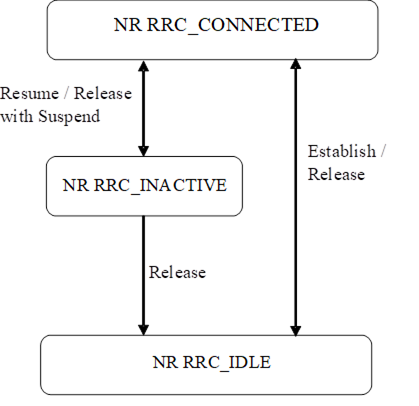
Figure 4.2.1-1: UE state machine and state
transitions in NR
Figure 4.2.1-2 illustrates an overview of
UE state machine and state transitions in NR as well as the mobility procedures
supported between NR/5GC, E-UTRA/EPC and E-UTRA/5GC.
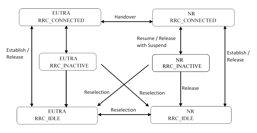
Figure 4.2.1-2: UE state machine and state
transitions between NR/5GC, E-UTRA/EPC and E-UTRA/5GC
Figure 4.2.1-3 illustrates the mobility
procedure supported between NR/5GC and UTRA-FDD.
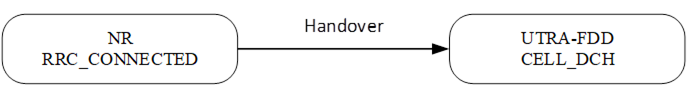
Figure 4.2.1-3: Mobility procedure supported
between NR/5GC and UTRA-FDD
"Signalling Radio Bearers" (SRBs)
are defined as Radio Bearers (RBs) that are used only for the transmission of RRC and NAS messages.
More specifically, the following SRBs are defined:
- SRB0 is for RRC messages using the CCCH
logical channel (except SRB0 of L2 U2N Remote UE);
- SRB1 is for RRC messages (which may include a
piggybacked NAS message) as well as for NAS messages prior to the establishment
of SRB2, all using DCCH logical channel (except SRB1 of
L2 U2N Remote UE);
- SRB2 is for NAS messages and for RRC messages
which include logged measurement information, all using DCCH logical channel (except SRB2 of L2 U2N Remote UE). SRB2 has
a lower priority than SRB1 and may be configured by the network after AS
security activation;
- SRB3 is for specific RRC messages when UE is
in (NG)EN-DC or NR-DC, all using DCCH logical channel;
- SRB4 is for RRC messages which include
application layer measurement report information, all using DCCH logical
channel. SRB4 has a lower priority than SRB1 and can only be configured by the
network after AS security activation.
- SRB5 is for RRC messages which include
application layer measurement report information, all using DCCH logical
channel. SRB5 has a lower priority than SRB1 and SRB3 and can only be
configured by the SN serving the SCG when the UE is in NR-DC, after AS security
activation.
In downlink, piggybacking of NAS messages
is used only for one dependant (i.e. with joint success/failure) procedure:
bearer establishment/modification/release. In uplink piggybacking of NAS
message is used only for transferring the initial NAS message during connection
setup and connection resume.
NOTE 1: The NAS messages transferred via SRB2 are
also contained in RRC messages, which however do not include any RRC protocol
control information.
Once AS security is activated, all RRC
messages on SRB1, SRB2, SRB3, SRB4 and SRB5, including those containing NAS
messages, are integrity protected and ciphered by PDCP. NAS independently
applies integrity protection and ciphering to the NAS messages, see TS 24.501
[23].
Split SRB is supported for all the MR-DC
options as well as MP in both SRB1 and SRB2 (split SRB is not supported for
SRB0, SRB3, SRB4 and SRB5).
For operation with shared spectrum channel
access in FR1, SRB0, SRB1 and SRB3 are assigned with the highest priority
Channel Access Priority Class (CAPC), (i.e. CAPC = 1) while CAPC for SRB2 is
configurable.
For the NR sidelink L2 U2N relay operations
not involved in MP, SRB0, SRB1, SRB2 of a L2 U2N Remote UE are not using Uu
CCCH/DCCH logical channels. The SRB0, SRB1, SRB2 of a L2 U2N Remote UE are
transmitted via the PC5 Relay RLC channels over PC5 and Uu Relay RLC channels
over Uu.
The RRC
protocol offers the following services to upper layers:
- Broadcast of
common control information;
- Notification
of UEs in RRC_IDLE, e.g. about a mobile terminating call;
- Notification
of UEs about ETWS and/or CMAS;
- Transfer of dedicated signalling;
- Broadcast of
positioning assistance data;
- Transfer of application layer measurement configuration and
reporting.
In brief,
the following are the main services that RRC expects from lower layers:
- Integrity
protection, ciphering and loss-less in-sequence delivery of information without
duplication;
The RRC
protocol includes the following main functions:
- Broadcast of system information:
- Including NAS common information;
- Information applicable for UEs in RRC_IDLE
and RRC_INACTIVE (e.g. cell (re-)selection parameters, neighbouring cell
information) and information (also) applicable for UEs in RRC_CONNECTED (e.g.
common channel configuration information);
- Including ETWS notification, CMAS
notification;
- Including positioning assistance data.
- RRC connection control:
- Paging;
- Establishment/modification/suspension/resumption/release
of RRC connection, including e.g. assignment/modification of UE identity
(C-RNTI, fullI-RNTI, etc.), establishment/modification/suspension/resumption/release
of SRBs (except for SRB0);
- Access barring;
- Initial AS security activation, i.e. initial
configuration of AS integrity protection (SRBs, DRBs) and AS ciphering (SRBs,
DRBs);
- RRC connection mobility including e.g.
intra-frequency and inter-frequency handover, path switch from a PCell to a
target L2 U2N Relay UE or from a L2 U2N Relay UE to a target PCell or from a
source L2 U2N Relay UE to a target L2 U2N Relay UE, associated AS security
handling, i.e. key/algorithm change, specification of RRC context information
transferred between network nodes;
- Establishment/modification/suspension/resumption/release
of RBs carrying user data (DRBs/MRBs);
- Radio configuration control including e.g.
assignment/modification of ARQ configuration, HARQ configuration, DRX
configuration;
- In case of DC, cell management including
e.g. change of PSCell, addition/modification/release of SCG cell(s);
- In case of CA, cell management including
e.g. addition/modification/release of SCell(s);
- In case of MP, path management including
e.g. addition/modification/release of indirect path;
- QoS control including assignment/
modification of semi-persistent scheduling (SPS) configuration and configured
grant configuration for DL and UL respectively, assignment/ modification of
parameters for UL rate control in the UE, i.e. allocation of a priority and a
prioritised bit rate (PBR) for each RB of UE and
logical channel of IAB-MT.
- Recovery from radio link failure.
- Inter-RAT mobility including e.g. AS security
activation, transfer of RRC context information;
- Measurement configuration and reporting:
- Establishment/modification/release of
measurement configuration (e.g. intra-frequency, inter-frequency and inter- RAT
measurements);
- Setup and release of measurement gaps;
- Measurement reporting.
- Configuration of BAP entity and BH RLC
channels for the support of IAB-node.
- Configuration of SRAP entity and Uu/PC5 Relay
RLC channels for the support of L2 U2N relay.
- Configuration of SRAP entity and PC5 Relay
RLC channels for the support of L2 U2U relay operation.
- Other functions including e.g. generic
protocol error handling, transfer of dedicated NAS information, transfer of UE
radio access capability information.
- Support of self-configuration and
self-optimisation.
- Support of measurement logging and reporting
for network performance optimisation, as specified in TS 37.320 [61];
- Support of transfer of
application layer measurement configuration and reporting.
- Configuration of side control information for
NCR-node.
This clause covers the general
requirements.
The UE shall:
1> process the received messages in order of
reception by RRC, i.e. the processing of a message shall be completed before
starting the processing of a subsequent message;
NOTE: Network may initiate a subsequent
procedure prior to receiving the UE's response of a previously initiated
procedure.
1> within a clause execute the steps according
to the order specified in the procedural description;
1> consider the term 'radio bearer' (RB) to
cover SRBs, DRBs and MRBs unless explicitly stated otherwise;
1> set the rrc-TransactionIdentifier in
the response message, if included, to the same value as included in the message
received from the network that triggered the response message;
1> upon receiving a choice value set to setup:
2> apply the corresponding received
configuration and start using the associated resources, unless explicitly
specified otherwise;
1> upon receiving a choice value set to release:
2> clear the corresponding configuration and
stop using the associated resources;
1> in case the size of a list is extended, upon
receiving an extension field comprising the entries in addition to the ones
carried by the original field (regardless of whether the network signals more
entries in total); apply the following generic behaviour unless explicitly
stated otherwise:
2> create a combined list by concatenating the
additional entries included in the extension field to the original field while
maintaining the order among both the original and the additional entries;
2> for the combined list, created according to
the previous, apply the same behaviour as defined for the original field.
In this specification, the UE considers
itself to be in:
- EN-DC, if and only if it is configured with nr-SecondaryCellGroupConfig
according to TS 36.331[10], and it is connected to
EPC,
- NGEN-DC, if and only if it is configured with
nr-SecondaryCellGroupConfig according to TS 36.331[10], and it is
connected to 5GC,
- NE-DC, if and only if it is configured with mrdc-SecondaryCellGroup
set to eutra-SCG,
- NR-DC, if and only if it is configured with mrdc-SecondaryCellGroup
set to nr-SCG,
- MR-DC, if and only if it is in (NG)EN-DC,
NE-DC or NR-DC.
NOTE: This use of these terms deviates from
the definition in TS 37.340 [41] and other
specifications. In TS 37.340, these terms include also
the case where the UE is configured with E-UTRA or NR MCG only (i.e. no NR or
E-UTRA SCG) but with one or more bearers terminated in a secondary node (i.e.
using NR PDCP).
The UE in (NG)EN-DC only executes a
subclause of clause 5 in this specification when the subclause:
- is referred to from a subclause under
execution, either in this specification or in TS 36.331 [10]; or
- applies to a message received on SRB3 (if
SRB3 is established); or
- applies to field(s), IE(s), UE variable(s) or
timer(s) in this specification that the UE is configured with.
When executing a subclause of clause 5 in
this specification, the UE follows the requirements in clause 5.1.2 and in all
subclauses of this specification applicable to the messages (including
processing time requirements), fields, IEs, timers and UE variables indicated
in the subclause under execution.
System Information (SI) is divided into the
MIB and a number of SIBs and posSIBs where:
- the MIB is always transmitted on the
BCH with a periodicity of 80 ms and repetitions made within 80 ms (TS 38.212
[17], clause 7.1) and it includes parameters that are needed to acquire SIB1
from the cell. The first transmission of the MIB
is scheduled in subframes as defined in TS 38.213 [13], clause 4.1 and
repetitions are scheduled according to the period of SSB;
NOTE 1: If the period of SSB is larger than 80
ms, the MIB is transmitted with the same periodicity as that of SSB.
- the SIB1 is transmitted on the DL-SCH
with a periodicity of 160 ms and variable transmission repetition periodicity
within 160 ms as specified in TS 38.213 [13], clause 13. The default
transmission repetition periodicity of SIB1 is 20 ms but the actual
transmission repetition periodicity is up to network implementation. For SSB
and CORESET multiplexing pattern 1, SIB1 repetition transmission period
is 20 ms. For SSB and CORESET multiplexing pattern 2/3, SIB1
transmission repetition period is the same as the SSB period (TS 38.213 [13],
clause 13). SIB1 includes information regarding the availability and
scheduling (e.g. mapping of SIBs to SI message, periodicity, SI-window size) of
other SIBs with an indication whether one or more SIBs are only provided
on-demand and, in that case, the configuration needed by the UE to perform the
SI request. SIB1 is cell-specific SIB;
- SIBs other than SIB1 and posSIBs are
carried in SystemInformation (SI) messages, which are transmitted on the
DL-SCH. Only SIBs or posSIBs having the same periodicity can be mapped to the
same SI message. SIBs and posSIBs are mapped to different SI messages, i.e. an
SI message contains either only SIBs or only posSIBs. Each SI message is
transmitted within periodically occurring time domain windows (referred to as
SI-windows with same length for all SI messages). Each SI message is associated
with an SI-window and the SI-windows of different SI messages do not overlap.
That is, within one SI-window only the corresponding SI message is transmitted.
An SI message may be repeated with the same content a number of times within
the SI-window. Any SIB or posSIB except SIB1 can be configured to be
cell specific or area specific, using an indication in SIB1. The cell
specific SIB is applicable only within a cell that provides the SIB while the area
specific SIB is applicable within an area referred to as SI area, which
consists of one or several cells and is identified by systemInformationAreaID;
- The mapping of SIBs to SI messages is
configured in schedulingInfoList and schedulingInfoList2, while
the mapping of posSIBs to SI messages is configured in posSchedulingInfoList
and schedulingInfoList2.
Each SIB and each posSIB is mapped to a single SI message. posSIBs of the
same posSibType carrying GNSS Generic Assistance Data for different
GNSS/SBAS (identified by gnss-id/sbas-id, see TS
37.355 [49]) are mapped to different SI messages.
Each SIB and posSIB is contained at most once in an SI message.
For SIBs and posSIBs with segments, the segments
contained in SI messages are transmitted according to the SI message
periodicity, with one segment of a particular sibType/posSibType
in each SI message;
- For a UE in RRC_CONNECTED, the network can
provide system information through dedicated signalling using the RRCReconfiguration
message, e.g. if the UE has an active BWP with no common search space
configured to monitor system information, paging, or upon request from the UE.
- For PSCell and SCells, the network provides
the required SI by dedicated signalling, i.e. within an RRCReconfiguration
message. Nevertheless, the UE shall acquire MIB of the PSCell to get SFN
timing of the SCG (which may be different from MCG). Upon change of relevant SI
for SCell, the network releases and adds the concerned SCell. For PSCell, the
required SI can only be changed with Reconfiguration with Sync.
NOTE 2: The physical layer imposes a limit to the
maximum size a SIB can take. The maximum SIB1 or SI message size
is 2976 bits.

Figure 5.2.2.1-1: System information acquisition
The UE applies the SI acquisition procedure
to acquire the AS, NAS- and positioning assistance data information. The
procedure applies to UEs in RRC_IDLE, in RRC_INACTIVE and in RRC_CONNECTED.
The UE in RRC_IDLE and RRC_INACTIVE shall
ensure having a valid version of (at least) the MIB, SIB1 through
SIB4, SIB5 (if the UE supports E-UTRA), SIB11 (if the UE
is configured for idle/inactive measurements), SIB12 (if UE is capable
of NR sidelink communication/discovery and is configured by upper layers to
receive or transmit NR sidelink communication/discovery), and SIB13, SIB14
(if UE is capable of V2X sidelink communication and is configured by upper
layers to receive or transmit V2X sidelink communication), SIB15 (if UE
is configured by upper layers to report disaster roaming related information), SIB16
(if the UE is capable of slice-based
cell reselection and the UE receives NSAG information for cell reselection from
upper layer), SIB17 or SIB17bis (if the UE is using TRS resources
for power saving in RRC_IDLE and RRC_INACTIVE), SIB19 (if UE is
accessing NR via NTN access), SIB22 (for ATG access), and SIB23 (if UE is capable of NR
sidelink positioning and is configured by upper layers to receive or transmit
SL-PRS).
The UE capable of
MBS broadcast which is receiving or interested to receive MBS broadcast
service(s) via a broadcast MRB shall ensure having a valid version of SIB20,
regardless of the RRC state the UE is in.
The UE shall ensure having a valid version
of the posSIB requested by upper layers.
The UE shall apply
the SI acquisition procedure as defined in clause 5.2.2.3 upon cell selection
(e.g. upon power on), cell-reselection, return from out of coverage, after
reconfiguration with sync completion, after entering the network from another
RAT, upon receiving an indication that the system
information has changed, upon receiving a PWS notification, upon receiving request (e.g., a positioning request) from upper
layers; and whenever the UE does not have a valid version of a stored SIB or
posSIB or a valid version of a requested SIB.
When the UE acquires a MIB or a SIB1
or an SI message in a serving cell as described in clause 5.2.2.3, and if the
UE stores the acquired SIB, then the UE shall store the associated areaScope,
if present, the first PLMN-Identity in the PLMN-IdentityInfoList
for non-NPN-only cells or the first NPN identity (SNPN identity in case of
SNPN, or PNI-NPN identity in case of PNI-NPN) in the NPN-IdentityInfoList
for NPN-only cells, the cellIdentity, the systemInformationAreaID,
if present, and the valueTag, if present, as indicated in the si-SchedulingInfo
for the SIB. If the UE stores the acquired posSIB, then the UE shall store the
associated areaScope, if present, the cellIdentity, the systemInformationAreaID,
if present, the valueTag, if provided in assistanceDataSIB-Element,
and the expirationTime if provided in assistanceDataSIB-Element. The
UE may use a valid stored version of the SI except MIB, SIB1, SIB6,
SIB7 or SIB8 e.g. after cell re-selection, upon return from out
of coverage or after the reception of SI change indication. The valueTag
and expirationTime for posSIB is optionally provided in assistanceDataSIB-Element,
as specified in TS 37.355 [49].
A L2 U2N Remote UE in RRC_IDLE or
RRC_INACTIVE can inform the interested SIB(s) to the connected L2 U2N Relay UE
as defined in clause 5.8.9.8.2 and receive the SIB(s) from the L2 U2N Relay UE
as defined in clause 5.8.9.9.3. A L2 U2N Remote UE in RRC_CONNECTED receives
SIB1 and other SIB(s) in RRCReconfiguration message and performs
on-demand SI request if required, as defined in clause 5.2.2.3.5 and 5.2.2.3.6.
The L2 U2N Remote UE in RRC_IDLE or RRC_INACTIVE or RRC_CONNECTED (when MP is
not configured) is not required to obtain SI over Uu interface, but it may
decide to perform the SI acquisition procedure over Uu interface as defined in
clause 5.2.2.3 by UE implementation.
NOTE: The storage and
management of the stored SIBs in addition to the SIBs valid for the current
serving cell is left to UE implementation.
The UE shall:
1> delete any stored version of a SIB after 3
hours from the moment it was successfully confirmed as valid;
1> for each stored version of a SIB:
2> if the areaScope
is associated and its value for the stored version of the SIB is the same as
the value received in the si-SchedulingInfo for that SIB from the
serving cell:
3> if the UE is NPN capable and the cell is an
NPN-only cell:
4> if the first NPN identity included in the NPN-IdentityInfoList,
the systemInformationAreaID and the valueTag that are included in
the si-SchedulingInfo for the SIB received from the serving cell are
identical to the NPN identity, the systemInformationAreaID and the valueTag
associated with the stored version of that SIB:
5> consider the stored SIB as valid for the
cell;
3> else if the first PLMN-Identity
included in the PLMN-IdentityInfoList, the systemInformationAreaID and the valueTag that are included in the si-SchedulingInfo for the SIB received from the serving cell are identical to the PLMN-Identity,
the systemInformationAreaID and the valueTag associated with the stored version of that
SIB:
4> consider the stored SIB as valid for the
cell;
2> if the areaScope is not present for
the stored version of the SIB and the areaScope value is not included in
the si-SchedulingInfo for that SIB from the serving cell:
3> if the UE is NPN capable and the cell is an
NPN-only cell:
4> if the first NPN identity in the NPN-IdentityInfoList,
the cellIdentity and valueTag that are included in the si-SchedulingInfo
for the SIB received from the serving cell are identical to the NPN identity,
the cellIdentity and the valueTag associated with the stored
version of that SIB:
5> consider the stored SIB as valid for the
cell;
3> else if the first PLMN-Identity in the PLMN-IdentityInfoList,
the cellIdentity and valueTag
that are included in the si-SchedulingInfo for the SIB received from the
serving cell are identical to
the PLMN-Identity, the cellIdentity and the valueTag
associated with the stored version of that SIB:
4> consider the stored SIB as valid for the cell;
1> for each stored version of a posSIB:
2> if the areaScope is associated and
its value for the stored version of the posSIB is the same as the value
received in the posSIB-MappingInfo for that posSIB from the serving cell
and the systemInformationAreaID included in the si-SchedulingInfo is identical to the systemInformationAreaID
associated with the stored version of that posSIB:
3> if the valueTag
(see TS 37.355 [49]) for the posSIB received from the serving cell is identical to the valueTag associated with the stored version
of that posSIB; or if the expirationTime (see TS 37.355 [49]) associated
with the stored posSIB has not been expired:
4> consider the stored posSIB as valid for the
cell;
2> if the areaScope is not present for
the stored version of the posSIB and the areaScope value is not included
in the posSIB-MappingInfo for that posSIB from the serving cell and the cellIdentity for the posSIB received from the serving cell is identical to the cellIdentity associated with the stored
version of that posSIB:
3> if the valueTag
(see TS 37.355 [49]) for the posSIB received from the serving cell is identical to the valueTag associated with the stored version
of that posSIB; or if the expirationTime (see TS 37.355 [49]) associated
with the stored posSIB has not been expired:
4> consider the stored posSIB as valid for the
cell;
A modification period is used, i.e. updated
SI message (other than SI message for ETWS, CMAS, positioning assistance data, and
some NTN-specific information as specified in the field descriptions) is
broadcasted in the modification period following the one where SI change
indication is transmitted. The modification period
boundaries are defined by SFN values for which SFN mod m = 0, where m is the
number of radio frames comprising the modification period. The modification
period is configured by system information. If H-SFN is provided in SIB1,
and UE is configured with eDRX, modification period boundaries are
defined by SFN values for which (H-SFN * 1024 + SFN) mod m = 0.
For UEs in RRC_IDLE or RRC_INACTIVE
configured to use an IDLE eDRX cycle longer than the modification period, an
eDRX acquisition period is defined. The boundaries of the eDRX acquisition
period are determined by H-SFN values for which H-SFN mod 1024 = 0.
The UE receives indications about SI
modifications and/or PWS notifications using Short Message transmitted with
P-RNTI over DCI (see clause 6.5). Repetitions of SI change indication may occur
within preceding modification period or within preceding eDRX acquisition
period. SI change indication is not applicable for SI messages containing
posSIBs.
UEs in RRC_IDLE or in RRC_INACTIVE while SDT
procedure is not ongoing shall monitor for SI change indication in its own
paging occasion(s) that the UE monitors as specified in TS 38.304 [20]. UEs in RRC_CONNECTED shall monitor for SI change indication in
any paging occasion at least once per modification period if the UE is provided
with common search space, including pagingSearchSpace, searchSpaceSIB1
and searchSpaceOtherSystemInformation, on the active BWP to monitor
paging, as specified in TS 38.213 [13], clause 13.
For UEs in RRC_INACTIVE while SDT procedure
is ongoing:
- if T319a is not running and if CG-SDT is
selected and if extended CG-SDT periodicity is configured (i.e. cg-SDT-PeriodicityExt
is configured), the UE shall monitor for SI change indication in its own paging
occasion(s) that the UE monitors as specified in TS 38.304 [20];
- in other cases, the UE shall monitor for SI
change indication in any paging occasion at least once per modification period,
if the initial downlink BWP on which the SDT procedure is ongoing is associated
with a CD-SSB.
During a modification period where ETWS or
CMAS transmission is started or stopped, the SI messages carrying the posSIBs
scheduled in posSchedulingInfoList may change, so the UE might not be
able to successfully receive those posSIBs in the remainder of the current
modification period and next modification period according to the scheduling
information received prior to the change.
ETWS or CMAS capable UEs in RRC_IDLE or in RRC_INACTIVE while SDT procedure
is not ongoing shall monitor for indications about PWS
notification in its own paging occasion(s) that the UE
monitors as specified in TS 38.304 [20]. ETWS or CMAS capable
UEs in RRC_CONNECTED shall
monitor for indication about PWS notification in any paging occasion at least once every defaultPagingCycle
if the UE is provided with common search space, including pagingSearchSpace,
searchSpaceSIB1 and searchSpaceOtherSystemInformation, on the
active BWP to monitor paging.
For ETWS or CMAS capable UEs in
RRC_INACTIVE while SDT procedure is ongoing: :
- if T319a is not running and if CG-SDT is
selected and if extended CG-SDT periodicity is configured (i.e. cg-SDT-PeriodicityExt
is configured), the UE shall monitor for indications
about PWS notification in its own paging occasion(s)
that the UE monitors as specified in TS 38.304 [20];
- in other cases, the UE shall monitor for
indication about PWS notification in any paging occasion at least once every defaultPagingCycle, if the initial downlink BWP on which the SDT procedure is ongoing
is associated with a CD-SSB.
For Short Message reception in a paging
occasion, the UE monitors the PDCCH monitoring
occasion(s) for paging as
specified in TS 38.304 [20] and TS 38.213 [13].
A L2 U2N Remote UE is not required to
monitor paging occasion for SI modifications and/or PWS notifications. It
obtains the updated system information and SIB6/7/8 from the connected L2 U2N
Relay UE as defined in clause 5.8.9.9.3.
If the UE receives a Short Message, the UE
shall:
1> if the UE is ETWS capable or CMAS capable,
the etwsAndCmasIndication bit of Short Message is set, and the UE is provided with searchSpaceSIB1 and searchSpaceOtherSystemInformation
on the active BWP or the initial BWP:
2> immediately re-acquire the SIB1;
2> if the UE is ETWS capable and si-SchedulingInfo
includes scheduling information for SIB6:
3> acquire SIB6, as specified in clause 5.2.2.3.2, immediately;
2> if the UE is ETWS capable and si-SchedulingInfo
includes scheduling information for SIB7:
3> acquire SIB7, as specified in clause 5.2.2.3.2, immediately;
2> if the UE is CMAS capable and si-SchedulingInfo
includes scheduling information for SIB8:
3> acquire SIB8, as specified in clause 5.2.2.3.2, immediately;
NOTE: In case SIB1, SIB6, SIB7,
or SIB8 overlap with a measurement gap it is left to UE implementation
how to immediately acquire SIB1, SIB6, SIB7, or SIB8.
1> if the UE does not operate an IDLE eDRX
cycle longer than the modification period and the systemInfoModification bit of Short Message is set:
2> apply the SI acquisition procedure as
defined in clause 5.2.2.3 from the start of the next modification period;
1> if the UE operates an IDLE eDRX cycle longer
than the modification period and the systemInfoModification-eDRX
bit of Short Message is set:
2> apply the SI acquisition procedure as
defined in clause 5.2.2.3 from the start of the next eDRX acquisition period
boundary.
The UE shall:
1> apply the specified BCCH configuration
defined in 9.1.1.1;
1> if the UE is in RRC_IDLE or in RRC_INACTIVE;
or
1> if the UE is in RRC_CONNECTED while T311 is running:
2> acquire the MIB, which is scheduled
as specified in TS 38.213 [13];
2> if the UE is unable to acquire the MIB;
3> perform the actions as specified in clause
5.2.2.5;
2> else:
3> perform the actions specified in clause
5.2.2.4.1.
1> if the UE is in RRC_CONNECTED with an active
BWP with common search space configured by searchSpaceSIB1 and pagingSearchSpace
and has received an indication about change of system information; or
1> if the UE is in RRC_CONNECTED with an active
BWP with common search space configured by searchSpaceSIB1 and the UE
has not stored a valid version of a SIB or posSIB, in accordance with clause
5.2.2.2.1, of one or several required SIB(s) or posSIB(s) in accordance with clause
5.2.2.1, and, UE has not acquired SIB1 in current modification period; or
1> if the UE is in RRC_CONNECTED with an active
BWP with common search space configured by searchSpaceSIB1, and, the UE
has not stored a valid version of a SIB or posSIB, in accordance with clause
5.2.2.2.1, of one or several required SIB(s) or posSIB(s) in accordance with clause
5.2.2.1, and, si-BroadcastStatus for the required
SIB(s) or posSI-BroadcastStatus for the required posSIB(s) is set to notBroadcasting in acquired
SIB1 in current modification period; or
1> if the UE is in RRC_IDLE or in RRC_INACTIVE;
or
1> if the UE is in RRC_CONNECTED while T311 is
running:
2> if ssb-SubcarrierOffset indicates SIB1
is transmitted in the cell (TS 38.213 [13]) and if SIB1 acquisition is
required for the UE:
3> acquire the SIB1, which is scheduled
as specified in TS 38.213 [13];
3> if the UE is unable to acquire the SIB1:
4> perform the actions as specified in clause
5.2.2.5;
3> else:
4> upon acquiring SIB1, perform the
actions specified in clause 5.2.2.4.2.
2> else if SIB1 acquisition is required
for the UE and ssb-SubcarrierOffset indicates that SIB1 is not
scheduled in the cell:
3> perform the actions as specified in clause
5.2.2.5.
NOTE 1: The UE in RRC_CONNECTED is only required
to acquire broadcasted SIB1 if the UE can acquire it without disrupting
unicast or MBS multicast data reception, i.e., the broadcast and unicast/MBS
multicast beams are quasi co-located. The UE in RRC_INACTIVE state while T319a
is running, is only required to acquire broadcasted SIB1 and MIB
if the UE can acquire them without disrupting unicast data reception, i.e. the
broadcast and unicast beams are quasi co-located.
NOTE 2: UE in
RRC_INACTIVE that does not support inactiveStateNTN-r17 enters RRC_IDLE
upon cell reselection between TN cell and NTN cell, and initiates the NAS
signalling connection recovery (see TS 24.501 [23]).
For SI message acquisition PDCCH monitoring
occasion(s) are determined according to searchSpaceOtherSystemInformation.
If searchSpaceOtherSystemInformation is set to zero, PDCCH monitoring
occasions for SI message reception in SI-window are same as PDCCH monitoring
occasions for SIB1 where the mapping between PDCCH monitoring occasions
and SSBs is specified in TS 38.213[13]. If searchSpaceOtherSystemInformation
is not set to zero, PDCCH monitoring occasions for SI message are determined
based on search space indicated by searchSpaceOtherSystemInformation.
PDCCH monitoring occasions for SI message which are not overlapping with UL
symbols (determined according to tdd-UL-DL-ConfigurationCommon) are
sequentially numbered from one in the SI window. The [x×N+K]th PDCCH
monitoring occasion (s) for SI message in SI-window corresponds to the Kth
transmitted SSB, where x = 0, 1, ...X-1, K = 1, 2, …N, N is the number of
actual transmitted SSBs determined according to ssb-PositionsInBurst in SIB1
and X is equal to CEIL(number of PDCCH monitoring occasions in SI-window/N).
The actual transmitted SSBs are sequentially numbered from one in ascending
order of their SSB indexes. The UE assumes that, in the SI window, PDCCH for an
SI message is transmitted in at least one PDCCH monitoring occasion
corresponding to each transmitted SSB and thus the selection of SSB for the
reception SI messages is up to UE implementation.
When acquiring an SI message, the UE shall:
1> determine the start of the SI-window for the
concerned SI message as follows:
2> if the concerned SI message is configured in
the schedulingInfoList:
3> for the concerned SI message, determine the
number n which corresponds to the order of entry in the list of SI
messages configured by schedulingInfoList in si-SchedulingInfo in
SIB1;
3> determine the integer value x = (n – 1) ×
w, where w is the si-WindowLength;
3> the SI-window starts at the slot #a,
where a = x mod N, in the radio frame for which SFN mod T
= FLOOR(x/N), where T is the si-Periodicity of the
concerned SI message and N is the number of slots in a radio frame as specified
in TS 38.211 [16];
2> else if the concerned
SI message is configured in the schedulingInfoList2;
3> determine the integer value x =
(si-WindowPosition -1) × w, where w is the si-WindowLength;
3> the SI-window starts at the slot #a,
where a = x mod N, in the radio frame
for which SFN mod T = FLOOR(x/N), where T is the si-Periodicity
of the concerned SI message and N is the number of slots in a radio frame as
specified in TS 38.211 [16];
2> else if the concerned SI message is
configured in the posSchedulingInfoList and offsetToSI-Used is
not configured:
3> create a concatenated list of SI messages by
appending the posSchedulingInfoList in posSI-SchedulingInfo in SIB1
to schedulingInfoList in si-SchedulingInfo in SIB1;
3> for the concerned SI message, determine the
number n which corresponds to the order of entry in the concatenated
list;
3> determine the integer value x = (n – 1) ×
w, where w is the si-WindowLength;
3> the SI-window starts at the slot #a,
where a = x mod N, in the radio frame for which SFN mod T
= FLOOR(x/N), where T is the posSI-Periodicity of the
concerned SI message and N is the number of slots in a radio frame as specified
in TS 38.211 [16];
2> else if the concerned SI message is
configured by the posSchedulingInfoList and offsetToSI-Used is
configured:
3> determine the number m which
corresponds to the number of SI messages with an associated si-Periodicity
of 8 radio frames (80 ms), configured by schedulingInfoList in SIB1;
3> for the concerned SI message, determine the
number n which corresponds to the order of entry in the list of SI
messages configured by posSchedulingInfoList in SIB1;
3> determine the integer value x = m
× w + (n – 1) × w, where w is the si-WindowLength;
3> the SI-window starts at the slot #a,
where a = x mod N, in the radio frame for which SFN mod T
= FLOOR(x/N) +8, where T is the posSI-Periodicity
of the concerned SI message and N is the number of slots in a radio frame as
specified in TS 38.211 [16];
1> receive the PDCCH containing the scheduling
RNTI, i.e. SI-RNTI in the PDCCH monitoring occasion(s) for SI message
acquisition, from the start of the SI-window and continue until the end of the
SI-window whose absolute length in time is given by si-WindowLength, or
until the SI message was received;
1> if the SI message was not received by the
end of the SI-window, repeat reception at the next SI-window occasion for the
concerned SI message in the current modification period;
1> if all the SIB(s) and/or posSIB(s) requested
in DedicatedSIBRequest message have been acquired:
2> stop timer T350, if running;
NOTE 1: The UE is only required to acquire
broadcasted SI message if the UE can acquire it without disrupting unicast or
MBS multicast data reception, i.e. the broadcast and unicast/MBS multicast
beams are quasi co-located.
NOTE 2: The UE is not required to monitor PDCCH
monitoring occasion(s) corresponding to each transmitted SSB in SI-window.
NOTE 3: If the concerned SI message was not
received in the current modification period, handling of SI message acquisition
is left to UE implementation.
NOTE 4: A UE in RRC_CONNECTED may stop the PDCCH
monitoring during the SI window for the concerned SI message when the requested
SIB(s) are acquired.
NOTE 5: A UE capable of NR sidelink communication/discovery
and configured by upper layers to perform NR sidelink communication/discovery
on a frequency, may acquire SIB12 or SystemInformationBlockType28
from a cell other than current serving cell (for RRC_INACTIVE or RRC_IDLE) or
current PCell (for RRC_CONNECTED), if SIB12 of current serving cell (for
RRC_INACTIVE or RRC_IDLE) or current PCell (for RRC_CONNECTED) does not provide
configuration for NR sidelink communication/discovery for the frequency, and if
the other cell providing configuration for NR sidelink communication/discovery
for the frequency meets the S-criteria as defined in TS 38.304 [20] or TS
36.304 [27].
1> perform the actions for the acquired SI
message as specified in clause 5.2.2.4.
The UE shall, while SDT procedure is not ongoing:
1> if SIB1 includes si-SchedulingInfo
containing si-RequestConfigSUL-MSG1-Repetition and criteria to select
supplementary uplink as defined in TS 38.321[3], clause 5.1.1 and criteria to
apply MSG1 repetition as defined in TS 38.321[3], clause 5.1.1e for the
concerned si-RequestConfigSUL-MSG1-Repetition are met:
2> trigger the lower layer to initiate the
Random Access procedure on supplementary uplink in accordance with TS 38.321
[3] using the PRACH preamble(s) and PRACH resource(s) associated with the
applicable MSG1 repetition number in si-RequestConfigSUL-MSG1-Repetition
corresponding to the SI message(s) that the UE requires to operate within the
cell, and for which si-BroadcastStatus is set to notBroadcasting;
2> if acknowledgement for SI request is
received from lower layers:
3> acquire the requested SI message(s) as
defined in clause 5.2.2.3.2, immediately;
1> else if the UE is an (e)RedCap UE and if initialUplinkBWP-RedCap is configured in UplinkConfigCommonSIB and if SIB1 includes si-SchedulingInfo containing si-RequestConfigRedCap-MSG1-Repetition
and criteria to select normal uplink as defined in TS 38.321[3], clause 5.1.1
and criteria to apply MSG1 repetition as defined in TS 38.321[3], clause 5.1.1e
for the concerned si-RequestConfigRedCap-MSG1-Repetition are met:
2> trigger the lower layer to initiate the
Random Access procedure on normal uplink in accordance with TS 38.321 [3] using
the PRACH preamble(s) and PRACH resource(s) associated with the applicable MSG1
repetition number in si-RequestConfigRedCap-MSG1-Repetition
corresponding to the SI message(s) that the UE requires to operate within the
cell, and for which si-BroadcastStatus is set to notBroadcasting;
2> if acknowledgement for SI request is
received from lower layers:
3> acquire the requested SI message(s) as
defined in clause 5.2.2.3.2, immediately;
1> else if SIB1 includes si-SchedulingInfo
containing si-RequestConfigSUL and criteria to select supplementary
uplink as defined in TS 38.321[3], clause 5.1.1 is met:
2> trigger the lower layer to initiate the
Random Access procedure on supplementary uplink in accordance with TS 38.321 [3]
using the PRACH preamble(s) and PRACH resource(s) in si-RequestConfigSUL
corresponding to the SI message(s) that the UE requires to operate within the
cell, and for which si-BroadcastStatus is set to notBroadcasting;
2> if acknowledgement for SI request is
received from lower layers:
3> acquire the requested SI message(s) as
defined in clause 5.2.2.3.2, immediately;
1> else if the UE is an (e)RedCap UE and if initialUplinkBWP-RedCap is configured in UplinkConfigCommonSIB and if SIB1 includes si-SchedulingInfo containing si-RequestConfigRedCap
and criteria to select normal uplink as defined in TS 38.321[3], clause 5.1.1
is met:
2> trigger the lower layer to initiate the
Random Access procedure on normal uplink in accordance with TS 38.321 [3] using
the PRACH preamble(s) and PRACH resource(s) in si-RequestConfigRedcap
corresponding to the SI message(s) that the UE requires
to operate within the cell, and for which si-BroadcastStatus is set to notBroadcasting;
2> if acknowledgement for SI request is
received from lower layers:
3> acquire the requested SI message(s) as
defined in clause 5.2.2.3.2, immediately;
1> else:
2> if the UE is neither
a RedCap nor an eRedCap UE and if SIB1 includes si-SchedulingInfo containing si-RequestConfigMSG1-Repetition
and criteria to select normal uplink as defined in TS 38.321 [3], clause 5.1.1 and
to apply MSG1 repetition as defined in TS 38.321[3], clause 5.1.1e for the
concerned si-RequestConfigMSG1-Repetition are met; or
2> if the UE is an (e)RedCap UE and if initialUplinkBWP-RedCap is not configured in UplinkConfigCommonSIB and if SIB1
includes si-SchedulingInfo containing si-RequestConfigMSG1-Repetition and criteria to
select normal uplink as defined in TS 38.321 [3], clause 5.1.1 and to apply
MSG1 repetition as defined in TS 38.321[3], clause 5.1.1e for the concerned si-RequestConfigMSG1-Repetition
are met:
3> trigger the lower layer to initiate the
Random Access procedure on normal uplink in accordance with TS 38.321 [3] using
the PRACH preamble(s) and PRACH resource(s) associated with the applicable MSG1
repetition number in si-RequestConfigMSG1-Repetition corresponding to
the SI message(s) that the UE requires to operate
within the cell, and for which si-BroadcastStatus is set to notBroadcasting;
3> if acknowledgement for SI request is
received from lower layers:
4> acquire the requested SI message(s) as
defined in clause 5.2.2.3.2, immediately;
2> else if the UE is neither
a RedCap nor an eRedCap UE and if SIB1 includes si-SchedulingInfo containing si-RequestConfig
and criteria to select normal uplink as defined in TS 38.321[3], clause 5.1.1
is met; or
2> if the UE is an (e)RedCap UE and if initialUplinkBWP-RedCap is not configured in UplinkConfigCommonSIB and if SIB1
includes si-SchedulingInfo containing si-RequestConfig and criteria to select normal
uplink as defined in TS 38.321[3], clause 5.1.1 is met:
3> trigger the lower layer to initiate the Random
Access procedure on normal uplink in accordance with TS 38.321 [3] using the
PRACH preamble(s) and PRACH resource(s) in si-RequestConfig
corresponding to the SI message(s) that the UE requires
to operate within the cell, and for which si-BroadcastStatus is set to notBroadcasting;
3> if acknowledgement for SI request is
received from lower layers:
4> acquire the requested SI message(s) as
defined in clause 5.2.2.3.2, immediately;
2> else:
3> apply the default L1 parameter values as
specified in corresponding physical layer specifications except for the
parameters for which values are provided in SIB1;
3> apply the default MAC Cell Group
configuration as specified in 9.2.2;
3> apply the timeAlignmentTimerCommon
included in SIB1;
3> apply the CCCH configuration as specified in
9.1.1.2;
3> initiate transmission of the RRCSystemInfoRequest
message with rrcSystemInfoRequest in accordance with 5.2.2.3.4;
3> if acknowledgement for RRCSystemInfoRequest
message with rrcSystemInfoRequest is received from lower layers:
4> acquire the requested SI message(s) as
defined in clause 5.2.2.3.2, immediately;
1> if cell reselection occurs while waiting for
the acknowledgment for SI request from lower layers:
2> reset MAC;
2> if SI request is based on RRCSystemInfoRequest
message with rrcSystemInfoRequest:
3> release RLC entity for SRB0.
NOTE: After RACH failure for SI request it is
up to UE implementation when to retry the SI request.
The UE shall, while SDT procedure is not ongoing:
1> if SIB1 includes posSI-SchedulingInfo
containing posSI-RequestConfigSUL-MSG1-Repetition and criteria to select
supplementary uplink as defined in TS 38.321[3], clause 5.1.1 and criteria to
apply MSG1 repetition as defined in TS 38.321[3], clause 5.1.1e for the
concerned posSI-RequestConfigSUL-MSG1-Repetition are met:
2> trigger the lower layer to initiate the
Random Access procedure on supplementary uplink in accordance with TS 38.321
[3] using the PRACH preamble(s) and PRACH resource(s) associated with the
applicable MSG1 repetition number in posSI-RequestConfigSUL-MSG1-Repetition
corresponding to the SI message(s) that the UE upper layers require for
positioning operations, and for which posSI-BroadcastStatus in posSchedulingInfoList
in posSI-SchedulingInfo or si-BroadcastStatus of the type2 SIB
configured by schedulingInfoList2 in si-SchedulingInfo-v1700, if
present, is set to notBroadcasting;
2> if acknowledgement for SI request is
received from lower layers:
3> acquire the requested SI message(s) as
defined in clause 5.2.2.3.2, immediately;
1> else if the UE is an (e)RedCap UE and if initialUplinkBWP-RedCap is configured in UplinkConfigCommonSIB and if SIB1 includes posSI-SchedulingInfo containing posSI-RequestConfigRedCap-MSG1-Repetition
and criteria to select normal uplink as defined in TS 38.321[3], clause 5.1.1
and criteria to apply MSG1 repetition as defined in TS 38.321[3], clause 5.1.1e
for the concerned posSI-RequestConfigRedCap-MSG1-Repetition are met:
2> trigger the lower layer to initiate the
Random Access procedure on normal uplink in accordance with TS 38.321 [3] using
the PRACH preamble(s) and PRACH resource(s) associated with the applicable MSG1
repetition number in posSI-RequestConfigRedCap-MSG1-Repetition
corresponding to the SI message(s) that the UE upper layers require for
positioning operations, and for which posSI-BroadcastStatus in posSchedulingInfoList
in posSI-SchedulingInfo or si-BroadcastStatus of the type2 SIB
configured by schedulingInfoList2 in si-SchedulingInfo-v1700, if
present, is set to notBroadcasting;
2> if acknowledgement for SI request is
received from lower layers:
3> acquire the requested SI message(s) as
defined in clause 5.2.2.3.2, immediately;
1> else if SIB1 includes posSI-SchedulingInfo
containing posSI-RequestConfigSUL and criteria to select supplementary
uplink as defined in TS 38.321[3], clause 5.1.1 is met:
2> trigger the lower layer to initiate the
Random Access procedure on supplementary uplink in accordance with TS 38.321 [3]
using the PRACH preamble(s) and PRACH resource(s) in posSI-RequestConfigSUL
corresponding to the SI message(s) that the UE upper layers require for
positioning operations, and for which posSI-BroadcastStatus in posSchedulingInfoList
in posSI-SchedulingInfo or si-BroadcastStatus of the type2 SIB
configured by schedulingInfoList2 in si-SchedulingInfo-v1700, if
present, is set to notBroadcasting;
2> if acknowledgement for SI request is
received from lower layers:
3> acquire the requested SI message(s) as
defined in clause 5.2.2.3.2, immediately;
1> else if the UE is an (e)RedCap UE and if initialUplinkBWP-RedCap is configured in UplinkConfigCommonSIB and if SIB1 includes posSI-SchedulingInfo containing posSI-RequestConfigRedCap
and criteria to select normal uplink as defined in TS 38.321[3], clause 5.1.1
is met:
2> trigger the lower layer to initiate the
Random Access procedure on normal uplink in accordance with TS 38.321 [3] using
the PRACH preamble(s) and PRACH resource(s) in posSI-RequestConfigRedCap
corresponding to the SI message(s) that the UE upper layers require for
positioning operations, and for which posSI-BroadcastStatus
in posSchedulingInfoList in posSI-SchedulingInfo
or si-BroadcastStatus of the type2 SIB configured by schedulingInfoList2
in si-SchedulingInfo-v1700, if present, is set
to notBroadcasting;
2> if acknowledgement for SI request is
received from lower layers:
3> acquire the requested SI message(s) as
defined in clause 5.2.2.3.2, immediately;
1> else:
2> if the UE is neither
a RedCap nor an eRedCap UE and if SIB1 includes posSI-SchedulingInfo containing posSI-RequestConfigMSG1-Repetition
and criteria to select normal uplink as defined in TS 38.321 [3], clause 5.1.1 and
to apply MSG1 repetition as defined in TS 38.321[3], clause 5.1.1e for the
concerned posSI-RequestConfigMSG1-Repetition are met; or
2> if the UE is an (e)RedCap UE and if initialUplinkBWP-RedCap is not configured in UplinkConfigCommonSIB and if SIB1
includes posSI-SchedulingInfo containing posSI-RequestConfigMSG1-Repetition and criteria
to select normal uplink as defined in TS 38.321 [3], clause 5.1.1, and to apply
MSG1 repetition as defined in TS 38.321[3], clause 5.1.1e for the concerned posSI-RequestConfigMSG1-Repetition
are met:
3> trigger the lower layer to initiate the
Random Access procedure on normal uplink in accordance with TS 38.321 [3] using
the PRACH preamble(s) and PRACH resource(s) associated with the applicable MSG1
repetition number in posSI-RequestConfigMSG1-Repetition corresponding to
the SI message(s) that the UE upper layers require for
positioning operations, and for which posSI-BroadcastStatus in posSchedulingInfoList in posSI-SchedulingInfo or si-BroadcastStatus of the type2 SIB configured by schedulingInfoList2 in si-SchedulingInfo-v1700,
if present, is set to notBroadcasting;
3> if acknowledgement for SI request is
received from lower layers:
4> acquire the requested SI message(s) as
defined in clause 5.2.2.3.2, immediately;
2> else if the UE is neither
a RedCap nor an eRedCap UE and if SIB1 includes posSI-SchedulingInfo containing posSI-RequestConfig
and criteria to select normal uplink as defined in TS 38.321[3], clause 5.1.1
is met; or
2> if the UE is an (e)RedCap UE and if initialUplinkBWP-RedCap is not configured in UplinkConfigCommonSIB and if SIB1
includes posSI-SchedulingInfo containing posSI-RequestConfig and criteria to select normal
uplink as defined in TS 38.321[3], clause 5.1.1 is met:
3> trigger the lower layer to initiate the Random
Access procedure on normal uplink in accordance with TS 38.321 [3] using the
PRACH preamble(s) and PRACH resource(s) in posSI-RequestConfig
corresponding to the SI message(s) that the UE upper layers require for
positioning operations, and for which posSI-BroadcastStatus
in posSchedulingInfoList in posSI-SchedulingInfo
or si-BroadcastStatus of the type2 SIB configured by schedulingInfoList2
in si-SchedulingInfo-v1700, if present, is set
to notBroadcasting;
3> if acknowledgement for SI request is
received from lower layers:
4> acquire the requested SI message(s) as
defined in clause 5.2.2.3.2, immediately;
2> else:
3> apply the default L1 parameter values as
specified in corresponding physical layer specifications except for the
parameters for which values are provided in SIB1;
3> apply the default MAC Cell Group
configuration as specified in 9.2.2;
3> apply the timeAlignmentTimerCommon
included in SIB1;
3> apply the CCCH configuration as specified in
9.1.1.2;
3> initiate transmission of the RRCSystemInfoRequest
message with rrcPosSystemInfoRequest in accordance with 5.2.2.3.4;
3> if acknowledgement for RRCSystemInfoRequest
message with rrcPosSystemInfoRequest is received from lower layers:
4> acquire the requested SI message(s) as
defined in clause 5.2.2.3.2, immediately;
1> if cell reselection occurs while waiting for
the acknowledgment for SI request from lower layers:
2> reset MAC;
2> if SI request is based on RRCSystemInfoRequest
message with rrcPosSystemInfoRequest:
3> release RLC entity for SRB0.
NOTE: After RACH failure for SI request it is
up to UE implementation when to retry the SI request.
The UE shall set the contents of RRCSystemInfoRequest
message as follows:
1> if the procedure is triggered to request the
required SI message(s) other than positioning:
2> set the requested-SI-List to indicate
the SI message(s) that the UE requires to operate
within the cell, and for which si-BroadcastStatus is set to notBroadcasting;
1> else if the procedure is triggered to request
the required SI message(s) for positioning:
2> set the requestedPosSI-List to
indicate the SI message(s) that the UE upper layers require for positioning
operations, and for which posSI-BroadcastStatus in posSchedulingInfoList in posSI-SchedulingInfo or si-BroadcastStatus
of the type2 SIB configured by schedulingInfoList2 in si-SchedulingInfo-v1700,
if present, is set to notBroadcasting.
The UE shall submit the RRCSystemInfoRequest
message to lower layers for transmission.
The UE shall:
1> if the UE is in RRC_CONNECTED with an active
BWP not configured with common search space with the field searchSpaceOtherSystemInformation
and the UE has not stored a valid version of a SIB or posSIB, in accordance
with clause 5.2.2.2.1, of one or several required SIB(s) or posSIB(s) in
accordance with clause 5.2.2.1, or
1> if the UE is in RRC_CONNECTED and acting as
a L2 U2N Remote UE and the UE has not stored a valid version of a SIB, in
accordance with clause 5.2.2.2.1, of one or several required SIB(s) in
accordance with clause 5.2.2.1:
2> for the SI message(s) that, according to the
si-SchedulingInfo or posSI-SchedulingInfo in the stored SIB1,
contain at least one required SIB or requested posSIB:
3> if onDemandSIB-Request is configured
and timer T350 is not running:
4> initiate transmission of the DedicatedSIBRequest
message in accordance with 5.2.2.3.6;
4> start timer T350 with the timer value set to
the onDemandSIB-RequestProhibitTimer;
1> else if the UE is in RRC_CONNECTED with an
active BWP configured with common search space with the field searchSpaceOtherSystemInformation
and the UE has not stored a valid version of a SIB or posSIB, in accordance
with clause 5.2.2.2.1, of one or several required SIB(s) or posSIB(s) in
accordance with clause 5.2.2.1:
2> for the SI message(s) that, according to the
si-SchedulingInfo in the stored SIB1, contain at least one required SIB
and for which si-BroadcastStatus is set to broadcasting:
3> acquire the SI message(s) as defined in clause
5.2.2.3.2;
2> for the SI message(s) that, according to the
si-SchedulingInfo in the stored SIB1, contain at least one required SIB
and for which si-BroadcastStatus is set to notBroadcasting:
3> if onDemandSIB-Request is configured
and timer T350 is not running:
4> initiate transmission of the DedicatedSIBRequest
message in accordance with 5.2.2.3.6;
4> start timer T350 with the timer value set to
the onDemandSIB-RequestProhibitTimer;
4> acquire the requested SI message(s)
corresponding to the requested SIB(s) as defined in clause 5.2.2.3.2.
2> for the SI message(s) that, according to the
posSI-SchedulingInfo or si-SchedulingInfo-v1700, if present, in
the stored SIB1, contain at least one requested posSIB and for which posSI-BroadcastStatus
in posSchedulingInfoList in posSI-SchedulingInfo or si-BroadcastStatus
of the type2 SIB configured by schedulingInfoList2 in si-SchedulingInfo-v1700,
if present, is set to broadcasting:
3> acquire the SI message(s) as defined in clause
5.2.2.3.2;
2> for the SI message(s) that, according to the
posSI-SchedulingInfo or si-SchedulingInfo-v1700, if present, in
the stored SIB1, contain at least one requested posSIB and for which posSI-BroadcastStatus
in posSchedulingInfoList in posSI-SchedulingInfo or si-BroadcastStatus
of the type2 SIB configured by schedulingInfoList2 in si-SchedulingInfo-v1700,
if present, is set to notBroadcasting:
3> if onDemandSIB-Request is configured
and timer T350 is not running:
4> initiate transmission of the DedicatedSIBRequest
message in accordance with 5.2.2.3.6;
4> start timer T350 with the timer value set to
the onDemandSIB-RequestProhibitTimer;
4> acquire the requested SI message(s)
corresponding to the requested posSIB(s) as defined in clause 5.2.2.3.2.
NOTE: UE may include on demand request for
SIB and/or posSIB(s) in the same DedicatedSIBRequest message.
The UE shall set the contents of DedicatedSIBRequest
message as follows:
1> if the procedure is triggered to request the
required SIB(s):
2> include requestedSIB-List in the onDemandSIB-RequestList
to indicate the requested SIB(s);
1> if the procedure is triggered to request the
required posSIB(s):
2> include requestedPosSIB-List in the onDemandSIB-RequestList
to indicate the requested posSIB(s).
The UE shall submit the DedicatedSIBRequest
message to lower layers for transmission.
Upon receiving the MIB the UE shall:
1> store the acquired MIB;
1> if the UE is in RRC_IDLE or in RRC_INACTIVE,
or if the UE is in RRC_CONNECTED while T311 is running:
2> if the access is not for NTN or the UE is
not capable of NTN; and
2> if the UE does not support nes-CellDTX-DRX;
and
2> if the access is not for ATG or the UE is not capable of ATG; and
2> if the UE is not IAB-MT; and
2> if the UE is not NCR-MT; and
2> if the cellBarred in the acquired MIB
is set to barred:
3> if the UE is an (e)RedCap UE or a 2Rx XR UE and
if ssb-SubcarrierOffset indicates SIB1 is transmitted in the cell
(TS 38.213 [13]):
4> acquire the SIB1, which is scheduled
as specified in TS 38.213 [13];
3> consider the cell as barred in accordance
with TS 38.304 [20];
3> perform cell re-selection to other cells on
the same frequency as the barred cell as specified in TS 38.304 [20];
2> else:
3> apply the received systemFrameNumber,
pdcch-ConfigSIB1, subCarrierSpacingCommon, ssb-SubcarrierOffset
and dmrs-TypeA-Position.
NOTE 1: A UE capable of NTN access should acquire
SIB1 to determine whether the cell is an NTN cell.
NOTE 2: A UE capable of ATG access should acquire SIB1 to determine whether the cell is an ATG cell.
NOTE 3: A UE indicating any of the values in nes-CellDTX-DRX
should acquire SIB1 to determine the cell barring status when the cellBarred
in MIB is set to barred.
Upon receiving the SIB1 the UE
shall:
1> store the acquired SIB1;
1> if the access is for NTN:
2> if the UE is in RRC_IDLE or in RRC_INACTIVE,
or if the UE is in RRC_CONNECTED while T311 is running:
3> if the cellBarredNTN in the acquired SIB1
is set to barred or the cellBarredNTN is not included in the
acquired SIB1:
4> consider the cell as barred in accordance
with TS 38.304 [20];
4> perform cell re-selection to other cells on
the same frequency as the barred cell as specified in TS 38.304 [20], upon
which the procedure ends;
3> if the UE is a fixed VSAT UE and the cellBarredFixedVSAT
in the acquired SIB1 is set to barred or the cellBarredFixedVSAT
is not included in the acquired SIB1, or
3> if the UE is a mobile VSAT UE and the cellBarredMobileVSAT
in the acquired SIB1 is set to barred or the cellBarredMobileVSAT
is not included in the acquired SIB1:
4> consider the cell as barred in accordance
with TS 38.304 [20];
4> perform cell re-selection to other cells on
the same frequency as the barred cell as specified in TS 38.304 [20], upon
which the procedure ends;
1> if the access is for ATG:
2> if the UE is in RRC_IDLE or in RRC_INACTIVE,
or if the UE is in RRC_CONNECTED while T311 is running; and
2> if the cellBarredATG in the acquired SIB1 is set
to barred or the cellBarredATG is not included in the acquired SIB1:
3> consider the cell as barred in accordance
with TS 38.304 [20];
3> perform cell re-selection to other cells on
the same frequency as the barred cell as specified in TS 38.304 [20], upon
which the procedure ends;
1> if the UE is a RedCap UE and it is in
RRC_IDLE or in RRC_INACTIVE, or if the RedCap UE is in RRC_CONNECTED while T311
is running:
2> if intraFreqReselectionRedCap is not
present in SIB1; or
2> if the halfDuplexRedCapAllowed is not
present in the acquired SIB1 and the UE supports only half-duplex FDD
operation:
3> consider the cell as barred in accordance
with TS 38.304 [20];
3> perform cell re-selection to other cells on
the same frequency as the barred cell as specified in TS 38.304 [20], upon
which the procedure ends;
2> else:
3> if the cellBarredRedCap1Rx is present in the acquired
SIB1 and is set to barred and the UE supports 1 Rx branch; or
3> if the cellBarredRedCap2Rx
is present in the acquired SIB1 and is set to barred and the UE supports
2 Rx branches:
4> evaluate the cell barring criteria in
accordance with TS 38.304 [20];
4> if the cell is
considered as barred;
5> perform cell re-selection to other cells on the same frequency as the barred
cell as specified in TS 38.304 [20], upon which the procedure ends;
1> if the UE is a 2Rx XR UE and is in RRC_IDLE
or in RRC_INACTIVE, or if the 2Rx XR UE is in RRC_CONNECTED while T311
is running:
2> if the cellBarred2RxXR is present in
the acquired SIB1:
3> evaluate the cell barring criteria in
accordance with TS 38.304 [20];
3> if the cell is
considered as barred;
4> perform cell re-selection to other cells on the same frequency as the barred
cell as specified in TS 38.304 [20] upon which the procedure ends;
1> if the UE supports nes-CellDTX-DRX
and it is in RRC_IDLE or in RRC_INACTIVE, or if the UE supporting nes-CellDTX-DRX
is in RRC_CONNECTED while T311 is running:
2> if cellBarred in the acquired MIB
is set to barred:
3> if cellBarredNES is absent in the
acquired SIB1:
4> consider the cell as barred in accordance
with TS 38.304 [20];
4> perform cell re-selection to other cells on
the same frequency as the barred cell as specified in TS 38.304 [20], upon
which the procedure ends;
1> if the UE is an eRedCap UE and it is in
RRC_IDLE or in RRC_INACTIVE, or if the eRedCap UE is in RRC_CONNECTED while T311
is running:
2> if intraFreqReselection-eRedCap is
not present in SIB1; or
2> if the halfDuplexRedCapAllowed is not
present in the acquired SIB1 and the UE supports only half-duplex FDD
operation:
3> consider the cell as barred in accordance
with TS 38.304 [20];
3> perform cell re-selection to other cells on
the same frequency as the barred cell as specified in TS 38.304 [20], upon which the procedure ends;
2> else:
3> if the cellBarred-eRedCap1Rx is
present in the acquired SIB1 and is set to barred and the UE supports
1 Rx branch; or
3> if the cellBarred-eRedCap2Rx
is present in the acquired SIB1 and is set to barred and the UE supports
2 Rx branches:
4> evaluate the cell barring criteria in
accordance with TS 38.304 [20];
4> if the cell is
considered as barred;
5> perform cell re-selection to other cells on the same
frequency as the barred cell as specified in TS 38.304
[20] upon which the procedure ends;
1> if the cellAccessRelatedInfo contains
an entry of a selected SNPN or PLMN and in case of PLMN the UE is either
allowed or instructed to access the PLMN via a cell for which at least one CAG
ID is broadcast:
2> in the remainder of the procedures use npn-IdentityList,
trackingAreaCode, and cellIdentity for the cell as received
in the corresponding entry of npn-IdentityInfoList containing the
selected PLMN or SNPN;
1> else if the cellAccessRelatedInfo
contains an entry with the PLMN-Identity of the selected PLMN:
2> in the remainder of the procedures use plmn-IdentityList,
trackingAreaCode, trackingAreaList, and cellIdentity for
the cell as received in the corresponding PLMN-IdentityInfo containing
the selected PLMN;
1> if the UE in RRC_INACTIVE is configured for
feature(s) that it does not support in current serving cell:
2> not use the corresponding configuration in
current serving cell;
NOTE 0: The requirement above applies only to UE
that indicates different support of UE capabilities for TN and NTN.
1> if in RRC_CONNECTED while T311 is not
running:
2> disregard the frequencyBandList, if
received, while in RRC_CONNECTED;
2> forward the cellIdentity to upper
layers;
2> forward the trackingAreaCode to upper
layers, if included;
2> forward the trackingAreaList to upper
layers, if included;
2> forward the received posSIB-MappingInfo
to upper layers, if included;
2> apply the configuration included in the servingCellConfigCommon;
2> if the UE has a stored valid version of a
SIB or posSIB, in accordance with clause 5.2.2.2.1, that the UE requires to operate within the cell in
accordance with clause 5.2.2.1:
3> use the stored version of the required SIB
or posSIB;
2> else:
3> acquire the required SIB or posSIB requested
by upper layer as defined in clause 5.2.2.3.5;
NOTE 1: Void.
1> else:
2> if the UE supports one or more of the
frequency bands indicated in the frequencyBandList or
frequencyBandListAerial for downlink for TDD, or one or more of the
frequency bands indicated in the frequencyBandList or frequencyBandListAerial
for uplink for FDD, and they are not downlink only bands, and
2> if the UE is IAB-MT or wide area NCR-MT (see
TS 38.106 [79]) or supports at least one additionalSpectrumEmission in
the nr-NS-PmaxList or nr-NS-PmaxListAerial for a supported band
in the downlink for TDD, or a supported band in uplink for FDD, and
2> if the UE supports
an uplink channel bandwidth with a maximum transmission bandwidth configuration
(see TS 38.101-1 [15], TS 38.101-2 [39], and TS 38.101-5 [75]) which
- is smaller than or
equal to the carrierBandwidth (indicated in uplinkConfigCommon
for the SCS of the initial uplink BWP or, for (e)RedCap UE, of the RedCap-specific
initial uplink BWP if configured), and which
- is wider than or equal to the bandwidth of
the initial uplink BWP or, for (e)RedCap UE, of the RedCap-specific initial
uplink BWP if configured, and
2> if the UE supports
a downlink channel bandwidth with a maximum transmission bandwidth
configuration (see TS 38.101-1 [15], TS 38.101-2 [39], and TS 38.101-5 [75])
which
- is smaller than or
equal to the carrierBandwidth (indicated in downlinkConfigCommon
for the SCS of the initial downlink BWP or, for (e)RedCap UE, of the RedCap-specific
initial downlink BWP if configured), and which
- is wider than or equal to the bandwidth of
the initial downlink BWP or, for (e)RedCap UE, of the RedCap-specific initial
downlink BWP if configured, and
2> if frequencyShift7p5khz is present and the UE supports
corresponding 7.5kHz frequency shift on this band; or frequencyShift7p5khz
is not present, and
2> if the UE is neither
a RedCap nor an eRedCap UE, or for TDD if the UE is an (e)RedCap UE, or for FDD
if the UE is an (e)RedCap UE and halfDuplexRedCapAllowed is present, or
if the UE is an (e)RedCap UE and the (e)RedCap UE supports full-duplex FDD
operation on this band:
3> if neither trackingAreaCode nor trackingAreaList
is provided for the selected PLMN nor the registered PLMN nor PLMN of the
equivalent PLMN list:
4> consider the cell as barred in accordance
with TS 38.304 [20];
4> perform cell re-selection to other cells on
the same frequency as the barred cell as specified in TS 38.304 [20], upon which the procedure ends;
3> else if UE is IAB-MT but not a mobile IAB-MT
and if iab-Support is not provided for the selected PLMN nor the
registered PLMN nor PLMN of the equivalent PLMN list nor the selected SNPN nor
the registered SNPN nor SNPN of the equivalent SNPN list:
4> consider the cell as barred in accordance
with TS 38.304 [20];
4> perform cell re-selection to other cells on
the same frequency as the barred cell as specified in TS 38.304 [20], upon which the procedure ends;
3> else if UE is NCR-MT and if ncr-Support is not provided:
4> consider the cell as barred in accordance
with TS 38.304 [20];
4> perform cell re-selection to other cells on
the same frequency as the barred cell as specified in TS 38.304 [20], upon which the procedure ends;
3> else if UE is a mobile IAB-MT and if mobileIAB-Support
is not provided for the selected PLMN nor the
registered PLMN nor PLMN of the equivalent PLMN list nor the selected SNPN nor
the registered SNPN nor SNPN of the equivalent SNPN list:
4> consider the cell as barred in accordance
with TS 38.304 [20];
4> perform cell re-selection to other cells on
the same frequency as the barred cell as specified in TS 38.304 [20], upon which the procedure ends;
3> else:
4> apply a supported uplink channel bandwidth
with a maximum transmission bandwidth which
- is contained within the carrierBandwidth
indicated in uplinkConfigCommon for the SCS of the initial uplink BWP
or, for (e)RedCap UEs, RedCap-specific initial uplink BWP, if configured, and
which
- is wider than or equal to the bandwidth of
the initial BWP for the uplink or, for a (e)RedCap UE, of the RedCap-specific
initial uplink BWP if configured;
4> apply a supported downlink channel bandwidth
with a maximum transmission bandwidth which
- is contained within the carrierBandwidth
indicated in downlinkConfigCommon for the SCS of the initial downlink
BWP or, for (e)RedCap UEs, RedCap-specific initial downlink BWP, if configured,
and which
- is wider than or equal to the bandwidth of the
initial BWP for the downlink or, for a (e)RedCap UE, of the RedCap-specific
initial downlink BWP if configured;
4> if the UE is aerial UE and it supports at
least one frequency band in the frequencyBandListAerial, for FDD from frequencyBandListAerial
for uplink, or for TDD from frequencyBandListAerial for downlink, for
which SIB1 includes nr-NS-PmaxListAerial and the UE supports at least
one of the additionalSpectrumEmission values in the
nr-NS-PmaxListAerial:
5> select the first frequency band in the frequencyBandListAerial,
for FDD from frequencyBandListAerial for uplink, or for TDD from frequencyBandListAerial
for downlink, which the UE supports and for which SIB1 includes nr-NS-PmaxListAerial
and the UE supports at least one of the additionalSpectrumEmission
values in the nr-NS-PmaxListAerial;
4> else if the UE is aerial UE and it supports
at least one frequency band in the frequencyBandListAerial, for FDD from
frequencyBandListAerial for uplink, or for TDD from frequencyBandListAerial
for downlink, for which SIB1 does not include nr-NS-PmaxListAerial
and the UE supports at least one of the additionalSpectrumEmission
values in the nr-NS-PmaxList within frequencyBandList for the
same NR frequency band number:
5> select the first frequency band in the frequencyBandListAerial,
for FDD from frequencyBandListAerial for uplink, or for TDD from frequencyBandListAerial
for downlink, which the UE supports and for which SIB1 does not
include nr-NS-PmaxListAerial and the UE supports at least one of the additionalSpectrumEmission
values in the nr-NS-PmaxList within frequencyBandList for the
same NR frequency band number;
4> else if the UE is aerial UE and SIB1
includes frequencyBandListAerial:
5> consider the cell as
barred in accordance with TS 38.304 [20];
5> perform cell re-selection to other cells on
the same frequency as the barred cell as if intraFreqReselection, or intraFreqReselectionRedCap
for RedCap UEs, or intraFreqReselection-eRedCap for eRedCap UEs is set
to notAllowed as specified in TS 38.304 [20], upon which the procedure
ends;
4> else:
5> select the first frequency band in the frequencyBandList,
for FDD from frequencyBandList for uplink, or for TDD from frequencyBandList
for downlink, which the UE supports and for which the UE supports at
least one of the additionalSpectrumEmission values in nr-NS-PmaxList,
if present, and for (e)RedCap UEs in FDD, if the halfDuplexRedCapAllowed
is not present, for which the UE supports full-duplex FDD operation;
4> forward the cellIdentity to upper
layers;
4> forward the trackingAreaCode to upper
layers;
4> forward the trackingAreaList to upper
layers, if included;
4> forward the received posSIB-MappingInfo
to upper layers, if included;
4> forward the PLMN identity or SNPN identity
or PNI-NPN identity to upper layers;
4> if in RRC_INACTIVE and the forwarded
information does not trigger message transmission by upper layers:
5> if the serving cell does not belong to the
configured ran-NotificationAreaInfo:
6> initiate an RNA update as specified in
5.3.13.8;
5> if configured to receive MBS multicast in
RRC_INACTIVE:
6> if SIB24 is not scheduled in SIB1 in the new
cell after cell selection (i.e., different from the cell where the UE was configured to receive multicast in
RRC_CONNECTED) or in the cell after cell reselection; or
6> if the PTM configuration is not available on
the multicast MCCH in the new cell after cell selection (i.e., different from
the cell where the UE was configured to receive multicast in RRC_CONNECTED) or
in the cell after cell reselection for at least one multicast session that the
UE has joined and for which the UE was indicated to stop monitoring G-RNTI;
7> initiate RRC connection resume procedure for
multicast reception as specified in 5.3.13.1d;
4> forward the ims-EmergencySupport to
upper layers, if present;
4> forward the eCallOverIMS-Support to
upper layers, if present;
4> forward the UAC-AccessCategory1-SelectionAssistanceInfo
or UAC-AC1-SelectAssistInfo for the selected PLMN/SNPN to
upper layers, if present and set to a, b or c;
4> if the UE is in SNPN access mode:
5> forward the imsEmergencySupportForSNPN
indicators with the corresponding SNPN identities to upper layers, if
present;
4> apply the configuration included in the servingCellConfigCommon;
4> apply the specified PCCH configuration
defined in 9.1.1.3;
4> if the UE has a stored valid version of a
SIB, in accordance with clause 5.2.2.2.1, that the UE requires
to operate within the cell in accordance with clause
5.2.2.1:
5> use the stored version of the required SIB;
4> if the UE has not stored a valid version of
a SIB, in accordance with clause 5.2.2.2.1, of one or several required SIB(s),
in accordance with clause 5.2.2.1:
5> for the SI message(s) that, according to the
si-SchedulingInfo, contain at least one required SIB and for which si-BroadcastStatus
is set to broadcasting:
6> acquire the SI message(s) as defined in clause
5.2.2.3.2;
5> for the SI message(s) that, according to the
si-SchedulingInfo, contain at least one required SIB and for which si-BroadcastStatus
is set to notBroadcasting:
6> trigger a request to acquire the SI
message(s) as defined in clause 5.2.2.3.3;
4> if the UE has a stored valid version of a
posSIB, in accordance with clause 5.2.2.2.1, of one or several required
posSIB(s), in accordance with clause 5.2.2.1:
5> use the stored version of the required
posSIB;
4> if the UE has not stored a valid version of
a posSIB, in accordance with clause 5.2.2.2.1, of one or several posSIB(s) in
accordance with clause 5.2.2.1:
5> for the SI message(s) that, according to the
posSI-SchedulingInfo or si-SchedulingInfo-v1700, if present,
contain at least one requested posSIB and for which posSI-BroadcastStatus
in posSchedulingInfoList in posSI-SchedulingInfo or si-BroadcastStatus
of the type2 SIB configured by schedulingInfoList2 in si-SchedulingInfo-v1700,
if present, is set to broadcasting:
6> acquire the SI message(s) as defined in clause
5.2.2.3.2;
5> for the SI message(s) that, according to the
posSI-SchedulingInfo or si-SchedulingInfo-v1700, if present,
contain at least one requested posSIB for which posSI-BroadcastStatus in
posSchedulingInfoList in posSI-SchedulingInfo or si-BroadcastStatus
of the type2 SIB configured by schedulingInfoList2 in si-SchedulingInfo-v1700,
if present, is set to notBroadcasting:
6> trigger a request to acquire the SI
message(s) as defined in clause 5.2.2.3.3a;
4> if the UE is aerial UE and, for the selected frequency band, it supports at
least one additionalSpectrumEmission value indicated by nr-NS-PmaxListAerial
within frequencyBandListAerial in uplinkConfigCommon for FDD or
in downlinkConfigCommon for TDD:
5> apply the first listed additionalSpectrumEmission which it
supports among the values indicated by nr-NS-PmaxListAerial for the
selected frequency band within frequencyBandListAerial in uplinkConfigCommon
for FDD or in downlinkConfigCommon for TDD;
4> else:
5> apply the first listed additionalSpectrumEmission
which it supports among the values included in nr-NS-PmaxList within
frequencyBandList in uplinkConfigCommon for FDD or in downlinkConfigCommon
for TDD;
4> if the additionalPmax is present in
the same entry of the selected additionalSpectrumEmission within nr-NS-PmaxList
or nr-NS-PmaxListAerial:
5> apply the additionalPmax for UL;
4> else:
5> apply the p-Max in uplinkConfigCommon
for UL;
4> if supplementaryUplink is present in servingCellConfigCommon;
and
4> if the UE supports one or more of the
frequency bands indicated in the frequencyBandList for the supplementaryUplink;
and
4> if the UE supports at least one additionalSpectrumEmission
in the nr-NS-PmaxList for a supported supplementary uplink band; and
4> if the UE is neither a RedCap nor an eRedCap
UE, or for TDD if the UE is an (e)RedCap UE, or for FDD if the UE is an (e)RedCap
UE and halfDuplexRedCapAllowed is present, or if the UE is an (e)RedCap
UE and the (e)RedCap UE supports full-duplex FDD operation on the frequency
bands indicated in the frequencyBandList for the supplementaryUplink;
and
4> if the UE supports an uplink channel
bandwidth with a maximum transmission bandwidth configuration (see TS 38.101-1
[15] and TS 38.101-2 [39]) which
- is smaller than or equal to the carrierBandwidth
(indicated in supplementaryUplink for the SCS of the initial uplink
BWP), and which
- is wider than or equal to the bandwidth of
the initial uplink BWP of the SUL:
5> consider supplementary uplink as configured
in the serving cell;
5> select the first frequency band in the frequencyBandList
for the supplementaryUplink which the UE supports and for which the
UE supports at least one of the additionalSpectrumEmission values in
nr-NS-PmaxList, if present, and for (e)RedCap UEs in FDD, if the halfDuplexRedCapAllowed
is not present, for which the UE supports full-duplex FDD operation;
5> apply a supported supplementary uplink
channel bandwidth with a maximum transmission bandwidth which
- is contained within the carrierBandwidth
(indicated in supplementaryUplink for the SCS of the initial uplink
BWP), and which
- is wider than or equal to the bandwidth of
the initial BWP of the SUL;
5> apply the first listed additionalSpectrumEmission
which it supports among the values included in nr-NS-PmaxList within frequencyBandList
for the supplementaryUplink;
5> if the additionalPmax is present in
the same entry of the selected additionalSpectrumEmission within nr-NS-PmaxList
for the supplementaryUplink:
6> apply the additionalPmax in supplementaryUplink
for SUL;
5> else:
6> apply the p-Max in supplementaryUplink
for SUL;
NOTE 2: For an out of coverage L2 U2N Remote UE in RRC_IDLE or RRC_INACTIVE
receiving SIB1 from its connected L2 U2N Relay UE, it is up to Remote UE
implementation whether to consider and apply the following parameters: frequencyBandList,
carrierBandwidth, frequencyShift7p5khz, frequency band, channel
bandwidth, the configuration included in the servingCellConfigCommon,
the specified PCCH configuration, additionalSpectrumEmission, additionalPmax,
and p-Max.
2> else:
3> consider the cell as barred in accordance
with TS 38.304 [20]; and
3> perform cell re-selection to other cells on
the same frequency as the barred cell as if intraFreqReselection, or intraFreqReselectionRedCap
for RedCap UEs, or intraFreqReselection-eRedCap for eRedCap UEs, or intraFreqReselection2RxXR
for 2Rx XR UEs is set to notAllowed as specified in TS 38.304 [20];
Upon receiving SIB2, the UE shall:
1> if in RRC_IDLE or in
RRC_INACTIVE or in RRC_CONNECTED while T311 is running:
2> if, for the entry in
frequencyBandList with the same index as the frequency band selected in
clause 5.2.2.4.2, the UE supports at least one additionalSpectrumEmission
in the nr-NS-PmaxList within the frequencyBandList; or
2> if, for the entry in
frequencyBandListAerial with the same index as the frequency band
selected in clause 5.2.2.4.2, the UE supports at least one additionalSpectrumEmission
value indicated by the nr-Ns-PmaxListAerial within the frequencyBandListAerial:
3> if the UE is aerial UE and it supports at
least one additionalSpectrumEmission value indicated by
nr-NS-PmaxListAerial:
4> apply the first listed additionalSpectrumEmission
which it supports among the values indicated by nr-NS-PmaxListAerial;
3> else:
4> apply the first
listed additionalSpectrumEmission which it supports among the values
included in nr-NS-PmaxList within frequencyBandList;
3> if the additionalPmax
is present in the same entry of the selected additionalSpectrumEmission
within nr-NS-PmaxList or nr-NS-PmaxListAerial:
4> apply the additionalPmax;
3> else:
4> apply the p-Max;
3> if the UE selects a frequency band (from the
procedure in clause 5.2.2.4.2) for the supplementary uplink:
4> if, for the entry in frequencyBandListSUL
with the same index as the frequency band selected in clause 5.2.2.4.2, the UE
supports at least one additionalSpectrumEmission in the nr-NS-PmaxList
within the frequencyBandListSUL:
5> apply the first
listed additionalSpectrumEmission which it supports among the values
included in nr-NS-PmaxList within frequencyBandListSUL;
5> if the additionalPmax is present in the same entry of the selected additionalSpectrumEmission
within nr-NS-PmaxList:
6> apply the additionalPmax;
5> else:
6> apply the p-Max;
4> else:
5> apply the p-Max.
2> else:
3> apply the p-Max;
No UE requirements related to the contents
of this SIB3 apply other than those specified elsewhere e.g. within
procedures using the concerned system information, and/ or within the
corresponding field descriptions.
Upon receiving SIB4 the UE shall:
1> if in RRC_IDLE, or in RRC_INACTIVE or in
RRC_CONNECTED while T311 is running:
2> for each entry in the interFreqCarrierFreqList:
3> if the UE is neither a RedCap nor an eRedCap
UE nor 2Rx XR UE; or
3> if the UE is a RedCap UE and the interFreqCarrierFreqList-v1700
is absent; or
3> if the UE is an eRedCap UE and the interFreqCarrierFreqList-v1800
is absent; or
3> if the UE is a 2Rx XR UE and the interFreqCarrierFreqList-v1800
is absent; or
3> if the UE is a RedCap UE and redCapAccessAllowed
is present in interFreqCarrierFreqList-v1700; or
3> if the UE is an eRedCap UE and eRedCapAccessAllowed
is present in interFreqCarrierFreqList-v1800; or
3> if the UE is a 2Rx XR UE and accessAllowed2RxXR
is present in interFreqCarrierFreqList-v1800:
4> select the first frequency band in the frequencyBandList
(or for aerial UE frequencyBandListAerial), and
frequencyBandListSUL, if present, which the UE supports and for which the
UE supports at least one of the additionalSpectrumEmission values in nr-NS-PmaxList
(or for aerial UE as indicated by nr-NS-PmaxListAerial), if present:
4> if, the frequency band selected by the UE in
frequencyBandList or frequencyBandListAerial to represent a
non-serving NR carrier frequency is not a downlink only band:
5> if, for the selected frequency band, the UE
supports at least one additionalSpectrumEmission in the nr-NS-PmaxList
within the frequencyBandList; or
5> if, for the selected frequency band, the UE
supports at least one additionalSpectrumEmission value indicated by the nr-NS-PmaxListAerial
within the frequencyBandListAerial:
6> if the UE is aerial UE and it supports at least one additionalSpectrumEmission
value indicated by nr-NS-PmaxListAerial:
7> apply the first listed additionalSpectrumEmission
which it supports among the values indicated by nr-NS-PmaxListAerial;
6> else:
7> apply the first listed additionalSpectrumEmission
which it supports among the values included in nr-NS-PmaxList within frequencyBandList;
6> if the additionalPmax is present in
the same entry of the selected additionalSpectrumEmission within nr-NS-PmaxList
or nr-NS-PmaxListAerial:
7> apply the additionalPmax;
6> else:
7> apply the p-Max;
6> if frequencyBandListSUL is present in
SIB4 and, for the frequency band selected in frequencyBandListSUL, the UE
supports at least one additionalSpectrumEmission in the nr-NS-PmaxList within FrequencyBandListSUL:
7> apply the first listed additionalSpectrumEmission
which it supports among the values included in nr-NS-PmaxList within frequencyBandListSUL;
7> if the additionalPmax is present in
the same entry of the selected additionalSpectrumEmission within nr-NS-PmaxList:
8> apply the additionalPmax;
7> else:
8> apply the p-Max;
6> else:
7> apply the p-Max;
5> else:
6> apply the p-Max;
1> if in RRC_IDLE or RRC_INACTIVE, and T331 is
running:
2> perform the actions as specified in
5.7.8.1a;
No UE requirements related to the contents
of this SIB5 apply other than those specified elsewhere e.g. within
procedures using the concerned system information, and/ or within the
corresponding field descriptions.
Upon receiving the SIB6 the UE
shall:
1> forward the received warningType, messageIdentifier
and serialNumber to upper layers;
Upon receiving the SIB7 the UE
shall:
1> if there is no current value for messageIdentifier
and serialNumber for SIB7; or
1> if either the received value of messageIdentifier
or of serialNumber, or of both messageIdentifier and serialNumber
are different from the current values of messageIdentifier and serialNumber
for SIB7:
2> use the received values of messageIdentifier
and serialNumber for SIB7 as the current values of messageIdentifier
and serialNumber for SIB7;
2> discard any previously buffered warningMessageSegment;
2> if all segments of a warning message have
been received:
3> assemble the warning message from the
received warningMessageSegment(s);
3> forward the received warning message, messageIdentifier,
serialNumber and dataCodingScheme to upper layers;
3> stop reception of SIB7;
3> discard the current values of messageIdentifier
and serialNumber for SIB7;
2> else:
3> store the received warningMessageSegment;
3> continue reception of SIB7;
1> else if all segments of a warning message
have been received:
2> assemble the warning message from the
received warningMessageSegment(s);
2> forward the received complete warning
message, messageIdentifier, serialNumber and dataCodingScheme
to upper layers;
2> stop reception of SIB7;
2> discard the current values of messageIdentifier
and serialNumber for SIB7;
1> else:
2> store the received warningMessageSegment;
2> continue reception of SIB7;
The UE should discard any stored warningMessageSegment
and the current value of messageIdentifier and serialNumber for SIB7
if the complete warning message has not been assembled within a period of 3
hours.
Upon receiving the SIB8 the UE
shall:
1> if the SIB8 contains a complete
warning message and the complete geographical area coordinates (if any):
2> forward the received warning message, messageIdentifier,
serialNumber, dataCodingScheme and the geographical area
coordinates (if any) to upper layers;
2> continue reception of SIB8;
1> else:
2> if the received values of messageIdentifier
and serialNumber are the same (each value is the same) as a pair for
which a warning message and the geographical area coordinates (if any) are
currently being assembled:
3> store the received warningMessageSegment;
3> store the received warningAreaCoordinatesSegment
(if any);
3> if all segments of a warning message and
geographical area coordinates (if any) have been received:
4> assemble the warning message from the
received warningMessageSegment;
4> assemble the geographical area coordinates
from the received warningAreaCoordinatesSegment (if any);
4> forward the received warning message, messageIdentifier,
serialNumber, dataCodingScheme and geographical area coordinates
(if any) to upper layers;
4> stop assembling a warning message and
geographical area coordinates (if any) for this messageIdentifier and serialNumber
and delete all stored information held for it;
3> continue reception of SIB8;
2> else if the received values of messageIdentifier
and/or serialNumber are not the same as any of the pairs for which a
warning message is currently being assembled:
3> start assembling a warning message for this messageIdentifier
and serialNumber pair;
3> start assembling the geographical area
coordinates (if any) for this messageIdentifier and serialNumber
pair;
3> store the received warningMessageSegment;
3> store the received warningAreaCoordinatesSegment
(if any);
3> continue reception of SIB8;
The UE should discard warningMessageSegment
and warningAreaCoordinatesSegment (if any) and the associated values of messageIdentifier
and serialNumber for SIB8 if the complete warning message and the
geographical area coordinates (if any) have not been assembled within a period
of 3 hours.
NOTE: The number of warning messages that a
UE can re-assemble simultaneously is a function of UE implementation.
Upon receiving SIB9 with referenceTimeInfo,
the UE may perform the related actions in clause 5.7.1.3 except for ignoring
all further referenceTimeInfo received in SIB9.
Upon receiving SIB9 with eventID-TSS,
the UE shall perform the actions below if requested by upper layers:
1> if the UE is NPN capable and the cell is an
NPN-only cell:
2> derive a gNB identity from gNB-ID-Length
and cellIdentity of the first NPN-IdentityInfo list entry of NPN-IdentityInfoList
in SIB1, and derive the plmn-Identity of
the first NPN-Identity list entry of NPN-IdentityList in SIB1 included
in the first NPN-IdentityInfo list entry of NPN-IdentityInfoList in
SIB1, as defined in
TS 38.413 [42];
1> else:
2> derive a gNB identity from gNB-ID-Length
and cellIdentity of the first PLMN-IdentityInfo list entry of
PLMN-IdentityInfoList in SIB1, and derive the plmn-Identity
of the first PLMN-IdentityInfo list entry of PLMN-IdentityInfoList
in SIB1, as defined in TS 38.413 [42];
1> if VarTSS-Info does not have a storedEventID;
or
1> if the storedEventID within VarTSS-Info
is different from the eventID-TSS received within SIB9; or
1> if the storedGlobalGnbID within the VarTSS-Info
is different from the global gNB identity derived from SIB1:
2> notify upper layers that clockQualityDetailsLevel
may have changed;
2> store the eventID-TSS received within
SIB9 as the storedEventID within VarTSS-Info;
2> store the global gNB identity derived from SIB1
as the storedGlobalGnbID within VarTSS-Info.
Upon receiving SIB10, the UE shall:
1> Forward the HRNN-list entries with the corresponding
PNI-NPN and SNPN identities to upper layers;
Upon receiving SIB11, the UE shall:
1> if in RRC_IDLE or RRC_INACTIVE, and T331 is
running:
2> perform the actions as specified in
5.7.8.1a;
Upon receiving SIB12, the UE shall:
1> if the UE has stored at least one segment of
SIB12 and the value tag of SIB12 has changed since a previous
segment was stored:
2> discard all stored segments;
1> store the segment;
1> if all segments have been received:
2> assemble SIB12-IEs from the received
segments;
2> if sl-FreqInfoList/sl-FreqInfoListSizeExt
is included in SIB12-IEs:
3> if configured to receive NR sidelink
communication:
4> use the resource pool(s) indicated by sl-RxPool
for NR sidelink communication reception, as specified in 5.8.7;
3> if configured to transmit NR sidelink
communication:
4> use the resource pool(s) indicated by sl-TxPoolSelectedNormal,
or sl-TxPoolExceptional for NR sidelink communication transmission, as
specified in 5.8.8;
4> perform CBR measurement on the transmission
resource pool(s) indicated by sl-TxPoolSelectedNormal or sl-TxPoolExceptional
for NR sidelink communication transmission, as specified in 5.5.3.1;
4> use the synchronization configuration
parameters for NR sidelink communication on frequencies included in sl-FreqInfoList/sl-FreqInfoListSizeExt,
as specified in 5.8.5;
3> if configured to perform SL-PRS measurement:
4> use the resource pool(s) indicated by sl-RxPool
for SL-PRS measurement, as
specified in 5.8.18.2;
3> if configured to transmit SL-PRS:
4> use the resource pool(s) indicated by sl-TxPoolSelectedNormal,
or sl-TxPoolExceptional for SL-PRS transmission, as specified in
5.8.18.3;
4> perform CBR measurement on the transmission
resource pool(s) indicated by sl-TxPoolSelectedNormal or sl-TxPoolExceptional
for SL-PRS, as specified in 5.5.3.1;
4> use the synchronization configuration
parameters for NR sidelink positioning on frequencies included in sl-FreqInfoList/sl-FreqInfoListSizeExt,
as specified in 5.8.5;
3> if configured to receive NR sidelink
discovery:
4> use the resource pool(s) indicated by sl-DiscRxPool
or sl-RxPool for NR sidelink discovery reception, as specified in 5.8.13.2;
3> if configured to transmit NR sidelink
discovery:
4> if the UE is configured by upper layers to
transmit NR sidelink L2 U2N relay discovery messages and sl-L2U2N-Relay is included in SIB12; or
4> if the UE is configured by upper layers to transmit NR sidelink L3 U2N relay discovery
messages and sl-L3U2N-RelayDiscovery is included
in SIB12; or
4> if the UE is configured by upper
layers to transmit NR sidelink non-relay discovery messages and sl-NonRelayDiscovery
is included in SIB12; or
4> if the UE is configured by upper layers to
transmit NR sidelink L2 U2U relay discovery messages and sl-L2-U2U-Relay is included in SIB12; or
4> if the UE is configured by upper
layers to transmit NR sidelink L3 U2U relay discovery messages and sl-L3-U2U-RelayDiscovery
is included in SIB12:
5> use the resource pool(s) indicated by sl-DiscTxPoolSelected,
sl-TxPoolExceptional or sl-TxPoolSelectedNormal for NR sidelink
discovery transmission, as specified in 5.8.13.3;
5> perform CBR
measurement on the transmission
resource pool(s) indicated by sl-TxPoolSelectedNormal, sl-DiscTxPoolSelected or sl-TxPoolExceptional for NR sidelink discovery transmission, as
specified in 5.5.3.1;
5> use the synchronization configuration
parameters for NR sidelink discovery on frequencies included in sl-FreqInfoList,
as specified in 5.8.5;
2> if sl-RadioBearerConfigList or sl-RLC-BearerConfigList
is included in sl-ConfigCommonNR:
3> perform sidelink DRB addition/modification/release as specified in
5.8.9.1a.1/5.8.9.1a.2;
3> if sl-RLC-BearerConfigListSizeExt is
included in SIB12-IEs:
4> perform additional sidelink RLC bearer addition/modification/release
as specified in 5.8.9.1a.5/5.8.9.1a.6;
2> if sl-MeasConfigCommon is included in sl-ConfigCommonNR:
3> store the NR sidelink measurement
configuration;
2> if sl-DRX-ConfigCommonGC-BC is included in SIB12-IEs:
3> store the NR sidelink DRX configuration and configure
lower layers to perform sidelink DRX operation for groupcast and broadcast as
specified in TS 38.321 [3];
1> if the UE is acting as L2 U2N Remote UE:
2> if the sl-TimersAndConstantsRemoteUE
is included in SIB12:
3> use values for timers T300, T301 and T319 as
included in the sl-TimersAndConstantsRemoteUE received in SIB12;
2> else:
3> use values for timers T300, T301 and T319 as
included in the ue-TimersAndConstants received in SIB1;
The UE should discard any stored segments
for SIB12 if the complete SIB12 has not been assembled within a
period of 3 hours. The UE shall
discard any stored segments for SIB12 upon cell (re-)selection.
NOTE: The L2 U2U UE is
allowed to use previous configuration based on SIB12 before receiving dedicated
configuration during and immediately after state transition from idle/inactive
to connected.
Upon receiving SIB13, the UE shall
perform the actions upon reception of SystemInformationBlockType21 as
specified in 5.2.2.28 in TS 36.331 [10].
Upon receiving SIB14, the UE shall
perform the actions upon reception of SystemInformationBlockType26 as
specified in 5.2.2.33 in TS 36.331 [10].
No UE requirements related to the contents
of the SIBpos apply other than those specified elsewhere e.g. within TS
37.355 [49], and/or within the corresponding field descriptions.
Upon receiving SIB15, the UE shall:
1> forward the applicable disaster roaming
information for each PLMN sharing the cell to upper layers.
Upon receiving SIB16 with cell
reselection priorities for slicing, the UE shall perform the actions as
specified in TS 38.304 [20].
Upon receiving SIB17, the UE shall:
1> if the UE has stored at least one segment of
SIB17 and the value tag of SIB17 has changed since a previous
segment was stored:
2> discard all stored segments;
1> store the segment;
1> if all segments have been received:
2> assemble SIB17-IEs from the received
segments.
The UE should discard any stored segments
for SIB17 if the complete SIB17 has not been assembled within a
period of 3 hours. The UE shall
discard any stored segments for SIB17 upon cell (re-) selection.
Upon receiving SIB17bis, the UE
shall:
1> if the UE has stored at least one segment of
SIB17bis and the value tag of SIB17bis has changed since a
previous segment was stored:
2> discard all stored segments;
1> store the segment;
1> if all segments have been received:
2> assemble SIB17bis-IEs from the
received segments.
The UE should discard any stored segments
for SIB17bis if the complete SIB17bis has not been assembled
within a period of 3 hours. The
UE shall discard any stored segments for SIB17bis upon cell (re-)
selection.
Upon receiving SIB18, the UE shall:
1> forward the Group
IDs for Network selection (GINs) in SIB18 with
the corresponding SNPN identities to upper layers;
Upon receiving SIB19 in an NTN cell,
the UE in RRC_CONNECTED shall:
1> start or restart T430 for serving cell with the
timer value set to ntn-UlSyncValidityDuration for the serving cell from
the subframe indicated by epochTime for the serving cell.
NOTE: UE should attempt to re-acquire SIB19
before the end of the duration indicated by ntn-UlSyncValidityDuration
and epochTime by UE implementation.
No UE requirements related to the contents
of SIB20 apply other than those specified elsewhere e.g. within
procedures using the concerned system information, and/or within the
corresponding field descriptions.
No UE requirements related to the contents
of SIB21 apply other than those specified elsewhere e.g. within
procedures using the concerned system information, and/or within the
corresponding field descriptions.
5.2.2.4.24 Actions upon reception of SIB22
No UE requirements related to the contents
of SIB22 apply other than those specified elsewhere e.g. within
procedures using the concerned system information, and/or within the
corresponding field descriptions.
5.2.2.4.25 Actions
upon reception of SIB23
Upon receiving SIB23, the UE shall:
1> if the UE has stored at least one segment of
SIB23 and the value tag of SIB23 has changed since a previous
segment was stored:
2> discard all stored segments;
1> store the segment;
1> if all segments have been received:
2> assemble SIB23-IEs from the received
segments;
2> if sl-PosFreqInfoList is included in sl-PosConfigCommonNR:
3> if configured to perform SL-PRS measurement:
4> use the resource pool(s) indicated by sl-PRS-RxPool
for SL-PRS measurement, as
specified in 5.8.18.2;
3> if configured to transmit SL-PRS:
4> use the resource pool(s) indicated by sl-PRS-TxPoolSelectedNormal
or sl-PRS-TxPoolExceptional for SL-PRS transmission, as specified in 5.8.18.3;
4> perform CBR measurement on the transmission
resource pool(s) indicated by sl-PRS-TxPoolSelectedNormal or sl-PRS-TxPoolExceptional
for SL-PRS transmission, as specified in 5.5.3.1;
4> use the synchronization configuration
parameters for NR sidelink positioning on frequencies included in sl-PosFreqInfoList,
as specified in 5.8.5;
The UE should discard any stored segments
for SIB23 if the complete SIB23 has not been assembled within a
period of 3 hours. The UE shall
discard any stored segments for SIB23 upon cell (re-)selection.
No UE requirements related to the contents
of SIB24 apply other than those specified elsewhere e.g., within
procedures using the concerned system information, and/or within the
corresponding field descriptions.
No UE requirements related to the contents
of SIB25 apply other than those specified elsewhere e.g. within
procedures using the concerned system information, and/or within the
corresponding field descriptions.
The UE shall:
1> if in RRC_IDLE or in RRC_INACTIVE or in
RRC_CONNECTED while T311 is running:
2> if the UE is unable to acquire the MIB or SIB1:
3> consider the cell as barred in accordance
with TS 38.304 [20];
3> perform cell re-selection to other cells on the same frequency as the barred
cell as specified in TS 38.304 [20].
NOTE 1: The SIB19 is essential for NTN access. If UE is unable to
acquire the SIB19 for NTN access, the action is up to UE implementation
(e.g., cell re-selection to other cells).
NOTE 2: The SIB22 is essential for ATG
access. If UE is unable to acquire the SIB22 for ATG access, the action
is up to UE implementation (e.g., cell re-selection to other cells).
The UE shall:
1> if T430 for serving cell expires and if in
RRC_CONNECTED:
2> inform lower layers that UL synchronisation
is lost;
2> acquire SIB19 as defined in clause
5.2.2.3.2;
2> upon successful acquisition of SIB19:
3> inform lower layers when UL synchronisation
is obtained;
NOTE: The exact time
when UL synchronisation is obtained (after SIB19 is acquired) is left to
UE implementation, which can be from the subframe indicated by epochTime
and optionally before the subframe indicated by epochTime.
RRC connection establishment involves the
establishment of SRB1. The network completes RRC connection establishment prior
to completing the establishment of the NG connection, i.e. prior to receiving
the UE context information from the 5GC. Consequently, AS security is not
activated during the initial phase of the RRC connection. During this initial
phase of the RRC connection, the network may configure the UE to perform
measurement reporting, but the UE only sends the corresponding measurement
reports after successful AS security activation. However, the UE only accepts a
re-configuration with sync message when AS security has been activated.
Upon receiving the UE context from the 5GC,
the RAN activates AS security (both ciphering and integrity protection) using
the initial AS security activation procedure. The RRC messages to activate AS
security (command and successful response) are integrity protected, while
ciphering is started only after completion of the procedure. That is, the
response to the message used to activate AS security is not ciphered, while the
subsequent messages (e.g. used to establish SRB2, DRBs and multicast MRBs) are
both integrity protected and ciphered. After having initiated the initial AS
security activation procedure, the network may initiate the establishment of
SRB2 and DRBs and/or multicast MRBs, i.e. the network may do this prior to
receiving the confirmation of the initial AS security activation from the UE.
In any case, the network will apply both ciphering and integrity protection for
the RRC reconfiguration messages used to establish SRB2, DRBs and/or multicast
MRBs. The network should release the RRC connection if the initial AS security
activation and/ or the radio bearer establishment fails. A configuration with
SRB2 without DRB or multicast MRB, or with DRB or multicast MRB without SRB2 is
not supported (i.e., SRB2 and at least one DRB or multicast MRB must be
configured in the same RRC Reconfiguration message, and it is not allowed to
release all the DRBs and multicast MRBs without releasing the RRC Connection).
For IAB-MT and NCR-MT, a configuration with SRB2 without any DRB/MRB is
supported.
The release of the RRC connection normally
is initiated by the network. The procedure may be used to re-direct the UE to
an NR frequency or an E-UTRA carrier frequency.
The suspension of the RRC connection is
initiated by the network. When the RRC connection is suspended, the UE stores
the UE Inactive AS context and any configuration received from the network, and
transits to RRC_INACTIVE state.
The RRC message to suspend the RRC connection is integrity protected and
ciphered.
The resumption of a suspended RRC
connection is initiated by upper layers when the UE needs to transit from
RRC_INACTIVE state to RRC_CONNECTED state or by RRC layer to perform a RNA
update or by RAN paging from
NG-RAN or for SDT or for multicast reception. When the RRC connection is
resumed, network configures the UE according to the RRC connection resume
procedure based on the stored UE Inactive AS context and any RRC configuration
received from the network. The RRC connection resume procedure re-activates AS
security and re-establishes SRB(s) and DRB(s) and/or multicast MRB(s), if
configured.
Upon initiating the resume procedure for
SDT, AS security (both ciphering and integrity protection) is re-activated for SRB2
(if configured for SDT) and for SRB1. In addition, AS security is also
re-activated (if security is configured) for all the DRBs configured for SDT.
Further, the PDCP entities of SRB1 and PDCP entities of the radio bearers
configured for SDT are re-established and resumed whilst the UE remains in
RRC_INACTIVE state. Transmission and reception of data and/or signalling
messages over radio bearers configured for SDT can happen whilst the UE is in
RRC_INACTIVE state and SDT procedure is ongoing.
In response to a request to resume the RRC
connection or in response to a resume procedure initiated for SDT, the network
may resume the suspended RRC connection and send UE to RRC_CONNECTED, or reject
the request to resume and send UE to RRC_INACTIVE (with a wait timer), or
directly re-suspend the RRC connection and send UE to RRC_INACTIVE, or directly
release the RRC connection and send UE to RRC_IDLE, or instruct the UE to
initiate NAS level recovery (in this case the network sends an RRC setup
message).
NOTE: In case the UE receives the
configurations for NR sidelink communication via the E-UTRA, the configurations
for NR sidelink communication in SIB12 and sl-ConfigDedicatedNR
within RRCReconfiguration used in clause 5.3 are provided by the
configurations in SystemInformationBlockType28 and sl-ConfigDedicatedForNR
within RRCConnectionReconfiguration as specified in TS 36.331[10],
respectively.
AS security comprises of the integrity
protection and ciphering of RRC signalling (SRBs) and user data (DRBs).
RRC handles the configuration of the AS
security parameters which are part of the AS configuration: the integrity
protection algorithm, the ciphering algorithm, if integrity protection and/or
ciphering is enabled for a DRB and two parameters, namely the keySetChangeIndicator
and the nextHopChainingCount, which are used by the UE to determine the
AS security keys upon reconfiguration with sync (with key change), connection
re-establishment and/or connection resume.
The integrity protection algorithm is
common for SRB1, SRB2, SRB3 (if configured), SRB4 (if configured), SRB5 (if
configured) and DRBs configured with integrity protection, with the same keyToUse
value. The ciphering algorithm is common for SRB1, SRB2, SRB3 (if configured),
SRB4 (if configured), SRB5 (if configured) and DRBs configured with the same keyToUse
value. Neither integrity protection nor ciphering applies for SRB0.
NOTE 0: All DRBs related to the same PDU session
have the same enable/disable setting for ciphering and the same enable/disable
setting for integrity protection, as specified in TS 33.501 [11].
RRC integrity protection and ciphering are
always activated together, i.e. in one message/procedure. RRC integrity
protection and ciphering for SRBs are never de-activated. However, it is
possible to switch to a 'NULL' ciphering algorithm (nea0).
The 'NULL' integrity protection
algorithm (nia0) is used only for SRBs and for the UE in limited service
mode, see TS 33.501 [11] and when used for SRBs, integrity protection is
disabled for DRBs. In case the ′NULL' integrity protection
algorithm is used, 'NULL' ciphering algorithm is also used.
NOTE 1: Lower layers discard RRC messages for
which the integrity protection check has failed and indicate the integrity
protection verification check failure to RRC.
The AS applies four different security
keys: one for the integrity protection of RRC signalling (KRRCint),
one for the ciphering of RRC signalling (KRRCenc), one for integrity
protection of user data (KUPint) and one for the ciphering of user
data (KUPenc). All four AS keys are derived from the KgNB
key. The KgNB key is based on the KAMF key (as specified
in TS 33.501 [11]), which is handled by upper layers.
The integrity protection and ciphering
algorithms can only be changed with reconfiguration with sync. The AS keys (KgNB,
KRRCint, KRRCenc, KUPint and KUPenc)
change upon reconfiguration with sync (if masterKeyUpdate is included),
and upon connection re-establishment and connection resume.
For each radio bearer an independent
counter (COUNT, as specified in TS 38.323 [5]) is maintained for each
direction. For each radio bearer, the COUNT is used as input for
ciphering and integrity protection.
It is not allowed to use the same COUNT
value more than once for a given security key. As specified in TS 33.501 clause
6.9.4.1 [11], the network is responsible for avoiding reuse of the COUNT
with the same RB identity and with the same key, e.g. due to the transfer of
large volumes of data, release and establishment of new RBs, and multiple
termination point changes for RLC-UM bearers and multiple termination point
changes for RLC-AM bearer with SN terminated PDCP re-establishment (COUNT
reset) due to SN only full configuration whilst the key stream inputs (i.e.
bearer ID, security key) at MN have not been updated. In order to avoid such
re-use, the network may e.g. use different RB identities for RB establishments,
change the AS security key, or an RRC_CONNECTED to RRC_IDLE/RRC_INACTIVE and
then to RRC_CONNECTED transition.
In order to limit the signalling overhead,
individual messages/ packets include a short sequence number (PDCP SN, as
specified in TS 38.323 [5]). In addition, an overflow counter mechanism is
used: the hyper frame number (HFN, as specified in TS 38.323 [5]). The
HFN needs to be synchronized between the UE and the network.
For each SRB, the value provided by RRC to
lower layers to derive the 5-bit BEARER parameter used as input for ciphering
and for integrity protection is the value of the corresponding srb-Identity
with the MSBs padded with zeroes.
For a UE provided with an sk-counter,
keyToUse indicates whether the UE uses the master key (KgNB)
or the secondary key (S-KeNB or S-KgNB) for a particular
DRB. The secondary key is derived from the master key and sk-Counter, as
defined in TS 33.501[11]. Whenever there is a need to refresh the secondary
key, e.g. upon change of MN with KgNB change or to avoid COUNT
reuse, the security key update is used (see 5.3.5.7). When the UE is in NR-DC,
the network may provide a UE configured with an SCG with an sk-Counter
even when no DRB is setup using the secondary key (S-KgNB) in order
to allow the configuration of SRB3. The network can also provide the UE with an
sk-Counter, even if no SCG is configured, when using SN terminated MCG
bearers.
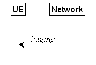
Figure 5.3.2.1-1: Paging
The purpose of this procedure is:
- to transmit paging information to a UE in
RRC_IDLE or RRC_INACTIVE.
- to transmit paging
information for a L2 U2N Remote UE in RRC_IDLE or RRC_INACTIVE to its serving
L2 U2N Relay UE in any RRC state.
The network initiates the paging procedure
by transmitting the Paging message at the UE's paging occasion as
specified in TS 38.304 [20]. The network may address multiple UEs within a Paging
message by including one PagingRecord for each UE. The network may also
include one or multiple TMGI(s) in the Paging message to page UEs for
specific MBS multicast session(s).
Upon receiving the Paging message by
the UE or receiving PagingRecord from its connected L2 U2N Relay UE by a
L2 U2N Remote UE, the UE shall:
1> if in RRC_IDLE, for each of the PagingRecord,
if any, included in the Paging message, or
1> if in RRC_IDLE, for the PagingRecord,
if any, included in the UuMessageTransferSidelink message received from the connected L2 U2N Relay UE:
2> if the ue-Identity included in the PagingRecord
matches the UE identity allocated by upper layers:
3> if upper layers indicate the support of paging
cause:
4> forward the ue-Identity, accessType
(if present) and paging cause (if determined) to the upper layers;
3> else:
4> forward the ue-Identity and accessType
(if present) to the upper layers;
NOTE 1: If
the L2 U2N Relay UE supports the MUSIM feature, it can forward the paging cause
to the connected L2 U2N Remote UE.
1> if in RRC_INACTIVE, for each of the PagingRecord,
if any, included in the Paging message, or
1> if in RRC_INACTIVE, for the PagingRecord,
if any, included in the UuMessageTransferSidelink message received from the connected L2 U2N Relay UE:
2> if the ue-Identity included in the PagingRecord
matches the UE's stored fullI-RNTI:
3> if the UE is configured by upper layers with
Access Identity 1:
4> initiate the RRC connection resumption
procedure according to 5.3.13 with resumeCause set to mps-PriorityAccess;
3> else if the UE is configured by upper layers
with Access Identity 2:
4> initiate the RRC connection resumption
procedure according to 5.3.13 with resumeCause set to mcs-PriorityAccess;
3> else if the UE is configured by upper layers
with one or more Access Identities equal to 11-15:
4> initiate the RRC connection resumption
procedure according to 5.3.13 with resumeCause set to highPriorityAccess;
3> else if mt-SDT indication was
included in the Paging message and if the conditions for initiating SDT
for a resume procedure initiated in response to RAN paging according to
5.3.13.1b are fulfilled:
4> if pagingGroupList was not included
in the Paging message; or
4> if pagingGroupList was included in
the Paging message but the UE has not joined any MBS session(s)
indicated by the TMGI(s) included in the pagingGroupList; or
4> if pagingGroupList was included in
the Paging message, all the MBS session(s) indicated by the TMGI(s)
included in the pagingGroupList that the UE has joined are configured to
be received in RRC_INACTIVE, and inactiveReceptionAllowed was included
for all these MBS session(s):
5> initiate the RRC connection resumption
procedure according to 5.3.13 with resumeCause set to mt-SDT;
NOTE 1a: If a UE receives a Paging message
including mt-SDT indication and inactiveReceptionAllowed
indications for all the multicast session(s) the UE has joined and the UE
initiates RRC connection resume, the UE starts monitoring the corresponding
G-RNTI(s), if configured, and if multicast MCCH is present, the UE starts
monitoring the Multicast MCCH-RNTI and acquires the MBSMulticastConfiguration
message on multicast MCCH.
4> else:
5> initiate the RRC connection resumption
procedure according to 5.3.13 with resumeCause set to mt-Access;
3> else:
4> initiate the RRC connection resumption
procedure according to 5.3.13 with resumeCause set to mt-Access;
NOTE 2: If both conditions for initiating MT-SDT
and MO-SDT according to 5.3.13.1b are fulfilled, UE may initiate RRC connection
resumption procedure for MT-SDT or MO-SDT based on implementation.
NOTE 3: A MUSIM UE may not initiate the RRC
connection resumption procedure, e.g. when it decides not to respond to the Paging
message due to UE implementation constraints as specified in TS 24.501 [23].
2> else if the ue-Identity included in
the PagingRecord matches the UE identity allocated by upper layers:
3> if upper layers indicate the support of
paging cause:
4> forward the ue-Identity, accessType
(if present) and paging cause (if determined) to the upper layers;
3> else:
4> forward the ue-Identity and accessType
(if present) to the upper layers;
3> perform the actions upon going to RRC_IDLE
as specified in 5.3.11 with release cause 'other';
1> if in RRC_IDLE, for
each TMGI included in pagingGroupList, if any, included in the Paging
message:
2> if the UE has joined an MBS session
indicated by the TMGI included in the pagingGroupList:
3> forward the TMGI to the upper layers;
1> if in RRC_INACTIVE and the UE has joined one
or more MBS session(s) indicated by the TMGI(s) included in the pagingGroupList:
2> if PagingRecordList is not included
in the Paging message; or
2> if none of the ue-Identity included
in any of the PagingRecord matches the UE identity allocated by upper
layers or the UE's stored fullI-RNTI:
3> if the UE is not configured to receive
multicast in RRC_INACTIVE for at least one of the MBS sessions indicated by the
TMGI(s) included in pagingGroupList that the UE has joined; or
3> if inactiveReceptionAllowed is not
included for at least one of the MBS sessions indicated by the TMGI(s) included
in pagingGroupList that the UE has joined:
4> initiate the RRC connection resumption
procedure according to 5.3.13.1d;
3> else:
4> start monitoring the G-RNTI(s), if
configured, corresponding to the TMGI(s);
4> if the UE was notified to stop monitoring
the G-RNTI(s) for all the joined multicast sessions that are configured for
reception in RRC_INACTIVE:
5> apply the multicast PTM configuration
provided in RRCRelease;
5> if multicast MCCH is present:
6> start monitoring the Multicast MCCH-RNTI;
6> acquire the MBSMulticastConfiguration
message on multicast MCCH;
4> else if the UE was notified to stop
monitoring the G-RNTI for at least one of the multicast sessions indicated by
the TMGI(s) included in pagingGroupList for which the PTM
configuration was not included in RRCRelease message:
5> apply the multicast PTM configuration
provided in RRCRelease;
5> acquire the MBSMulticastConfiguration
message on multicast MCCH;
2> else if the ue-Identity included in
any of the PagingRecord matches the UE identity allocated by upper
layers:
3> forward the TMGI(s) to the upper
layers;
1> if the UE is acting as a L2 U2N Relay UE,
for each of the PagingRecord, if any, included in the Paging
message:
2> if the ue-Identity included in the PagingRecord
in the Paging message matches the UE identity in sl-PagingIdentityRemoteUE
included in sl-PagingInfo-RemoteUE received in RemoteUEInformationSidelink
message from a L2 U2N Remote UE:
3> inititate the Uu Message transfer in
sidelink to that UE as specified in 5.8.9.9;
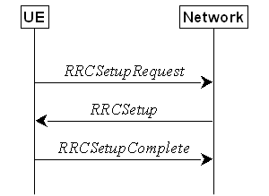
Figure 5.3.3.1-1: RRC connection establishment,
successful
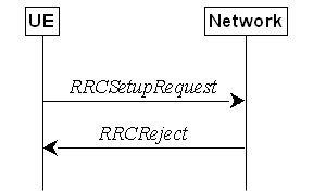
Figure 5.3.3.1-2: RRC connection establishment,
network reject
The purpose of this procedure is to
establish an RRC connection. RRC connection establishment involves SRB1
establishment. The procedure is also used to transfer the initial NAS dedicated
information/ message from the UE to the network.
The network applies the procedure e.g.as
follows:
- When establishing an RRC connection;
- When UE is resuming or re-establishing an RRC
connection, and the network is not able to retrieve or verify the UE context.
In this case, UE receives RRCSetup and responds with RRCSetupComplete.
For NR sidelink communication/discovery, an
RRC connection establishment is initiated only in the following cases:
1> if configured by upper layers to transmit NR
sidelink communication and related data is available for transmission:
2> if the frequency on which the UE is
configured to transmit NR sidelink communication is included in sl-FreqInfoList/sl-FreqInfoListSizeExt
within SIB12 provided by the cell on which the UE camps; and if the
valid version of SIB12 does not include sl-TxPoolSelectedNormal
for the concerned frequency;
1> if configured by upper layers to transmit NR
sidelink discovery and related data is available for transmission:
2> if the UE is configured by upper layers to
transmit NR sidelink L2 U2N relay discovery messages and sl-L2U2N-Relay
is included in SIB12; or
2> if the UE is configured by upper layers to
transmit NR sidelink L3 U2N relay discovery messages and sl-L3U2N-RelayDiscovery
is included in SIB12; or
2> if the UE is configured by upper layers to
transmit NR sidelink non-relay discovery messages and sl-NonRelayDiscovery
is included in SIB12:
3> if the frequency on which the UE is
configured to transmit NR sidelink discovery is included in sl-FreqInfoList within
SIB12 provided by the
cell on which the UE camps; and if the valid version of SIB12 includes neither sl-DiscTxPoolSelected nor sl-TxPoolSelectedNormal
for the concerned frequency;
For L2 U2N Relay UE in RRC_IDLE, an RRC connection establishment is
initiated in the following cases:
1> if any message is received from a L2 U2N Remote UE via SL-RLC0 as specified in
9.1.1.4 or SL-RLC1 as specified in 9.2.4; or
1> if RemoteUEInformationSidelink
containing the connectionForMP is received from a L2 U2N Remote UE as
specified in 5.8.9.8.3;
For V2X sidelink communication, an RRC
connection is initiated only when the conditions specified for V2X sidelink
communication in clause 5.3.3.1a of TS 36.331 [10] are met.
NOTE 1: Upper layers initiate an RRC connection
(except if the RRC connection is initiated at the L2 U2N Relay UE upon
reception of a message from a L2 U2N Remote UE via SL-RLC0 or SL-RLC1, or upon
reception of RemoteUEInformationSidelink message containing the connectionForMP).
The interaction with NAS is left to UE implementation.
For N3C relay UE in RRC_IDLE, an RRC
connection establishment is initiated when a N3C remote UE indicates it to
enter RRC_CONNECTED state.
NOTE 2: How/when the N3C remote UE to indicate N3C relay UE to enter
RRC_CONNECTED state is left to UE implementation, e.g. before reporting relay UE information with non-3GPP connection(s).
The UE initiates the procedure when upper
layers request establishment of an RRC connection while the UE is in RRC_IDLE
and it has acquired essential system information, or for sidelink communication
as specified in clause 5.3.3.1a.
The UE shall ensure having valid and up to
date essential system information as specified in clause 5.2.2.2 before
initiating this procedure.
Upon initiation of the procedure, the UE
shall:
1> if the upper layers provide an Access
Category and one or more Access Identities upon requesting establishment of an
RRC connection:
2> perform the unified access control procedure
as specified in 5.3.14 using the Access Category and Access Identities provided
by upper layers;
3> if the access attempt is barred, the
procedure ends;
1> if the upper layers provide NSAG information
and one or more S-NSSAI(s) triggering the access attempt (TS 23.501 [32] and TS 24.501 [23]):
2> apply the NSAG with highest NSAG priority
among the NSAGs that are included in SIB1 (i.e., in
FeatureCombination and/or in RA-PrioritizationSliceInfo), and
that are associated with the S-NSSAI(s) triggering the access attempt, in the
Random Access procedure (TS 38.321 [3], clause 5.1);
NOTE: If there are
multiple NSAGs with the same highest NAS-provided NSAG priority identified for
access attempt as above, it is
left to UE implementation to select the NSAG to be applied in the Random Access
procedure.
1> if the UE is acting as L2 U2N Remote UE:
2> establish a SRAP entity as specified in TS
38.351 [66], if no SRAP entity has been established;
2> apply the specified configuration of SL-RLC0 as specified in 9.1.1.4;
2> apply the SDAP configuration and PDCP
configuration as specified in 9.1.1.2 for SRB0;
1> else:
2> apply the default L1 parameter values as
specified in corresponding physical layer specifications except for the
parameters for which values are provided in SIB1;
2> apply the default MAC Cell Group
configuration as specified in 9.2.2;
2> apply the CCCH configuration as specified in
9.1.1.2;
2> apply the timeAlignmentTimerCommon
included in SIB1;
1> start timer T300;
1> initiate transmission of the RRCSetupRequest
message in accordance with 5.3.3.3;
The UE shall set the contents of RRCSetupRequest
message as follows:
1> set the ue-Identity as follows:
2> if upper layers provide a 5G-S-TMSI:
3> set the ue-Identity to ng-5G-S-TMSI-Part1;
2> else:
3> draw a 39-bit random value in the range 0..239-1
and set the ue-Identity to this value;
NOTE 1: Upper layers provide the 5G-S-TMSI
if the UE is registered in the TA of the current cell.
1> if the establishment of the RRC connection
is the result of release with redirect with mpsPriorityIndication
(either in NR or E-UTRAN):
2> set the establishmentCause to mps-PriorityAccess;
1> else:
2> set the establishmentCause in
accordance with the information received from upper layers;
NOTE 2: In case the L2
U2N Relay UE initiates RRC connection establishment triggered either by
reception of message from a L2 U2N Remote UE via
SL-RLC0 or SL-RLC1, or by reception of message RemoteUEInformationSidelink
containing the connectionForMP, as specified in 5.3.3.1a, the L2 U2N
Relay UE sets the establishmentCause by implementation, but: (1) for
SL-RLC0, it can only set the emergency, mps-PriorityAccess, or mcs-PriorityAccess
as establishmentCause if the same cause value is in the message received from the L2 U2N Remote UE via SL-RLC0; and (2) for SL-RLC1, it sets the establishmentCause to emergency
if the message received from the L2 U2N Remote UE via SL-RLC1 is over PC5 link
established for emergency service as indicated by upper layer [72].
1> if ta-Report or
ta-ReportATG is configured with value enabled and the UE supports TA
reporting:
2> indicate TA report initiation to lower
layers;
The UE shall submit the RRCSetupRequest
message to lower layers for transmission.
If the UE is an (e)RedCap UE and the RedCap-specific
initial downlink BWP is not associated with CD-SSB, the UE may continue cell
re-selection related measurements as well as cell re-selection evaluation,
otherwise the UE shall continue cell re-selection related measurements as well
as cell re-selection evaluation. If the conditions for cell re-selection are
fulfilled, the UE shall perform cell re-selection as specified in 5.3.3.6.
NOTE 3: For L2 U2N Remote
UE in RRC_IDLE, the cell (re)selection procedure as specified in TS 38.304 [20]
and relay (re)selection procedure as specified in 5.8.15.3 are performed
independently and up to UE implementation to select either a cell or a L2 U2N
Relay UE.
The UE shall perform the following actions
upon reception of the RRCSetup:
1> if the RRCSetup
is received in response to an RRCReestablishmentRequest; or
1> if the RRCSetup
is received in response to an RRCResumeRequest or RRCResumeRequest1:
2> if the UE is NCR-MT:
3> indicate to NCR-Fwd to cease forwarding;
2> if sdt-MAC-PHY-CG-Config is
configured:
3> instruct the MAC entity to stop the cg-SDT-TimeAlignmentTimer,
if it is running;
3> instruct the MAC entity to start the timeAlignmentTimer
associated with the PTAG indicated by tag-Id, if it is not running;
2> if srs-PosRRC-Inactive is configured:
3> instruct the MAC entity to stop the inactivePosSRS-TimeAlignmentTimer,
if it is running;
2> if srs-PosRRC-InactiveValidityAreaPreConfigList or srs-PosRRC-InactiveValidityAreaNonPreConfig is configured:
3> instruct the MAC entity to stop the inactivePosSRS-ValidityAreaTAT, if it is
running;
2> if the UE is
configured to receive MBS multicast in RRC_INACTIVE:
3> reset MAC;
2> discard any stored
UE Inactive AS context and suspendConfig;
2> discard any current AS security context
including the KRRCenc key, the KRRCint key, the KUPint
key and the KUPenc key;
2> release radio resources for all established
RBs except SRB0 and broadcast MRBs, including release of the RLC entities, of
the associated PDCP entities and of SDAP;
2> release the RRC configuration except for the
default L1 parameter values, default MAC Cell Group configuration, CCCH
configuration and broadcast MRBs;
2> indicate to upper layers fallback of the RRC
connection;
2> for each application layer measurement
configuration with appLayerIdleInactiveConfig absent:
3> forward the measConfigAppLayerId and inform
upper layers about the release of the application layer measurement
configuration;
3> release the application layer measurement
configuration;
3> discard any application layer measurement
reports which were not yet fully submitted to lower layers for transmission;
3> consider itself not to be configured to send
application layer measurement reports for the measConfigAppLayerId;
2> stop timer T380, if running;
1> perform the cell group configuration
procedure in accordance with the received masterCellGroup and as
specified in 5.3.5.5;
1> perform the radio bearer configuration
procedure in accordance with the received radioBearerConfig and as
specified in 5.3.5.6;
1> if stored, discard the cell reselection
priority information provided by the cellReselectionPriorities or
inherited from another RAT;
1> stop timer T300, T301, T319;
1> if T319a is running:
2> stop T319a;
2> consider SDT procedure is not ongoing;
1> if T390 is running:
2> stop timer T390 for all access categories;
2> perform the actions as specified in
5.3.14.4;
1> if T302 is running:
2> stop timer T302;
2> perform the actions as specified in
5.3.14.4;
1> stop timer T320, if running;
1> if the RRCSetup is received in
response to an RRCResumeRequest, RRCResumeRequest1 or RRCSetupRequest:
2> if T331 is running:
3> stop timer T331;
3> perform the actions as specified in 5.7.8.3;
2> enter RRC_CONNECTED;
2> stop the cell re-selection procedure;
2> stop relay (re)selection procedure if any
for L2 U2N Remote UE;
1> consider the current cell to be the PCell;
1> perform the L2 U2N Remote UE configuration
procedure in accordance with the received sl-L2RemoteUE-Config as
specified in 5.3.5.16;
1> perform the sidelink dedicated configuration
procedure in accordance with the received sl-ConfigDedicatedNR as specified in 5.3.5.14;
1> if the UE has radio link failure or handover
failure information available in VarRLF-Report and if the RPLMN is
included in plmn-IdentityList stored in VarRLF-Report; or
1> if the UE has radio link failure or handover
failure information available in VarRLF-Report and if the current
registered SNPN identity is included in snpn-IdentityList stored in VarRLF-Report:
2> if reconnectCellId in VarRLF-Report
is not set after failing to perform reestablishment and if this is the first RRCSetup received by the UE after
declaring the failure:
3> if the UE supports RLF-Report
for conditional handover and if choCellId in VarRLF-Report
is set:
4> set timeUntilReconnection in VarRLF-Report
to the time that elapsed since the radio link failure or handover failure
experienced in the failedPCellId stored in VarRLF-Report;
3> else:
4> set timeUntilReconnection in VarRLF-Report
to the time that elapsed since the last radio link failure or handover failure;
3> set nrReconnectCellId in reconnectCellId
in VarRLF-Report to the global cell identity and the tracking area
code of the PCell;
1> if the UE supports RLF report for inter-RAT
MRO NR as defined in TS 36.306 [62], and if the UE has radio link failure or
handover failure information available in VarRLF-Report of TS 36.331
[10] and if the RPLMN is included in plmn-IdentityList stored in VarRLF-Report
of TS 36.331 [10]:
2> if reconnectCellId in VarRLF-Report
of TS 36.331[10] is not set after failing to perform
reestablishment and if this is the first RRCSetup
received by the UE after declaring the failure:
3> set timeUntilReconnection in VarRLF-Report
of TS 36.331[10] to the time that elapsed since the last radio link failure or
handover failure in LTE;
3> set nrReconnectCellId in reconnectCellId
in VarRLF-Report of TS 36.331[10] to the global cell identity and
the tracking area code of the PCell;
1> for each application layer measurement
configuration with appLayerIdleInactiveConfig configured:
2> if the RPLMN is not included in plmn-IdentityList
in VarAppLayerPLMN-ListConfig:
3> forward the measConfigAppLayerId and
inform upper layers about the release of the application layer measurement
configuration;
3> release the application layer measurement
configuration including its fields in the UE variables VarAppLayerIdleConfig
and VarAppLayerPLMN-ListConfig;
3> discard any application layer measurement
reports which were not yet fully submitted to lower layers for transmission;
3> consider itself not to be configured to send
application layer measurement reports for the measConfigAppLayerId;
1> set the content of RRCSetupComplete
message as follows:
2> if upper layers provide a 5G-S-TMSI:
3> if the RRCSetup is received in
response to an RRCSetupRequest:
4> set the ng-5G-S-TMSI-Value to ng-5G-S-TMSI-Part2;
3> else:
4> set the ng-5G-S-TMSI-Value to ng-5G-S-TMSI;
2> if upper layers selected an SNPN or a PLMN
and in case of PLMN UE is either allowed or instructed to access the PLMN via a
cell for which at least one CAG ID is broadcast:
3> set the selectedPLMN-Identity from
the npn-IdentityInfoList;
2> else:
3> set the selectedPLMN-Identity to the
PLMN selected by upper layers from the plmn-IdentityInfoList;
2> if upper layers provide the 'Registered
AMF':
3> include and set the registeredAMF as
follows:
4> if the PLMN identity of the 'Registered AMF'
is different from the PLMN selected by the upper layers:
5> include the plmnIdentity in the registeredAMF
and set it to the value of the PLMN identity in the 'Registered AMF' received
from upper layers;
4> set the amf-Identifier to the value
received from upper layers;
3> include and set the guami-Type to the
value provided by the upper layers;
2> if upper layers provide one or more S-NSSAI
(see TS 23.003 [21]):
3> include the s-NSSAI-List and set the
content to the values provided by the upper layers;
2> if upper layers provide onboarding request
indication:
3> include the onboardingRequest;
2> set the dedicatedNAS-Message to
include the information received from upper layers;
2> if connecting as an IAB-node but not as a
mobile IAB-node:
3> include the iab-NodeIndication;
2> else if connecting as a mobile IAB-node:
3> include the mobileIAB-NodeIndication;
2> if connecting as an NCR-node:
3> include the ncr-NodeIndication;
2> if the SIB1 contains idleModeMeasurementsNR
and the UE has NR idle/inactive measurement information concerning cells other than
the PCell available in VarMeasIdleReport; or
2> if the SIB1 contains idleModeMeasurementsEUTRA
and the UE has E-UTRA idle/inactive measurement information available in VarMeasIdleReport:
3> include the idleMeasAvailable;
2> if the SIB1 contains reselectionMeasurementsNR
and the UE has valid NR reselection measurements available for any
frequency listed in measReselectionCarrierListNR in VarMeasReselectionConfig:
3> include the reselectionMeasAvailable;
2> if the UE has logged measurements available
for NR and if the RPLMN is included in plmn-IdentityList stored in VarLogMeasReport;
or
2> if the UE has logged measurements available
for NR and if the current registered SNPN identity is included in snpn-ConfigID-List
stored in VarLogMeasReport:
3> include the logMeasAvailable in the RRCSetupComplete message;
3> if Bluetooth measurement results are
included in the logged measurements the UE has available for NR:
4> include the logMeasAvailableBT in the RRCSetupComplete message;
3> if WLAN measurement results are included in
the logged measurements the UE has available for NR:
4> include the logMeasAvailableWLAN in the RRCSetupComplete message;
2> if the sigLoggedMeasType in VarLogMeasReport is
included; or
2> if the UE supports the override protection of
the signalling based logged MDT for inter-RAT (i.e. LTE
to NR), and if the sigLoggedMeasType in VarLogMeasReport
of TS 36.331 [10] is included:
3> if T330 timer is running (associated to the
logged measurement configuration for NR or for LTE):
4> set sigLogMeasConfigAvailable to true
in the RRCSetupComplete
message;
3> else:
4> if the UE has logged measurements in VarLogMeasReport
or in VarLogMeasReport of TS 36.331 [10]:
5> set sigLogMeasConfigAvailable to false
in the RRCSetupComplete
message;
2> if the UE has connection establishment
failure or connection resume failure information available in VarConnEstFailReport
or VarConnEstFailReportList and if the RPLMN is equal to plmn-Identity stored in VarConnEstFailReport
or in at least one of the entries of VarConnEstFailReportList; or
2> if the UE has connection establishment
failure information or connection resume failure information available in VarConnEstFailReport or VarConnEstFailReportList and if the
current registered SNPN identity is equal to snpn-Identity stored in VarConnEstFailReport or any entry of VarConnEstFailReportList:
3> include connEstFailInfoAvailable in the RRCSetupComplete message;
2> if the UE has radio link failure or handover
failure information available in VarRLF-Report and if the RPLMN is
included in plmn-IdentityList stored in VarRLF-Report, or
2> if the UE has radio link failure or handover
failure information available in VarRLF-Report of TS 36.331 [10], and if
the UE is capable of cross-RAT RLF reporting and if the RPLMN is included in plmn-IdentityList
stored in VarRLF-Report of TS 36.331 [10]; or
2> if the UE has radio link failure or handover
failure information available in VarRLF-Report and if the current registered SNPN identity is included in snpn-IdentityList
stored in the VarRLF-Report:
3> include rlf-InfoAvailable in the RRCSetupComplete message;
2> if the UE has successful handover
information available in VarSuccessHO-Report and if the RPLMN is
included in plmn-IdentityList stored in VarSuccessHO-Report; or
2> if the UE has successful handover
information available in VarSuccessHO-Report and if the current registered SNPN identity is included in snpn-IdentityList
stored in the VarSuccessHO-Report:
3> include successHO-InfoAvailable in the RRCSetupComplete
message;
2> if the UE has successful PSCell change or
addition information available in VarSuccessPSCell-Report and if the
RPLMN is included in plmn-IdentityList stored in VarSuccessPSCell-Report;
or
2> if the UE has successful PSCell change or
addition information available in VarSuccessPSCell-Report and if the current registered SNPN identity is included in snpn-IdentityList
stored in the VarSuccessPSCell-Report:
3> include successPSCell-InfoAvailable in the RRCSetupComplete message;
2> if the UE supports storage of mobility
history information and the UE has mobility history information available in VarMobilityHistoryReport:
3> include the mobilityHistoryAvail in the RRCSetupComplete message;
2> if the UE has at least one stored
application layer measurement configuration with appLayerIdleInactiveConfig
configured:
3> include measConfigReportAppLayerAvailable
in the RRCSetupComplete message;
2> if the UE supports uplink RRC message
segmentation of UECapabilityInformation according to the network
indication rrc-SegAllowed:
3> may include the ul-RRC-Segmentation in the RRCSetupComplete message;
2> if the UE supports
uplink RRC message segmentation of UECapabilityInformation according to the network indication rrc-MaxCapaSegAllowed:
3> include the ul-RRC-MaxCapaSegments in the RRCSetupComplete message;
2> if the RRCSetup
is received in response to an RRCResumeRequest, RRCResumeRequest1
or RRCSetupRequest:
3> if speedStateReselectionPars is
configured in the SIB2:
4> include the mobilityState in the RRCSetupComplete message and set it to the mobility state (as specified in TS 38.304
[20]) of the UE just prior to entering RRC_CONNECTED state;
2> if SIB1 contains musim-CapRestrictionAllowed:
3> if supported, include the musim-CapRestrictionInd in the RRCSetupComplete
message upon determining it has temporary capability
restriction;
2> if the UE has flight path information available:
3> include flightPathInfoAvailable;
1> submit the RRCSetupComplete message
to lower layers for transmission, upon which the procedure ends.
NOTE: Upon reception
of musim-CapRestrictionInd in RRCSetupComplete, it is up to
network implementation to configure the UE with a limited configuration that is
used until network sends RRCReconfiguration based on the actual
restricted UE capabilities included in UEAssistanceInformation.
The UE shall:
1> perform the actions as specified in 5.3.15;
The UE shall:
1> if cell reselection occurs while T300 or
T302 is running; or
1> if relay (re)selection or cell selection by
a L2 U2N Remote UE occurs while T300 is running; or
1> if cell changes due to relay (re)selection or
cell selection by a L2 U2N Remote UE while T302 is running:
2> perform the actions upon going to RRC_IDLE
as specified in 5.3.11 with release cause 'RRC connection failure';
1> else:
2> if cell selection or reselection occurs
while T390 is running; or
2> cell change due to relay selection or
reselection occurs while T390 is running:
3> stop T390 for all access categories;
3> perform the actions as specified in
5.3.14.4.
The UE shall:
1> if timer T300 expires:
2> reset MAC, release the MAC configuration and
re-establish RLC for all RBs that are established (except broadcast MRBs);
2> if the UE supports
RRC Connection Establishment failure with temporary offset and the T300 has expired a consecutive connEstFailCount times on
the same cell for which connEstFailureControl is included in SIB1:
3> for a period as indicated by connEstFailOffsetValidity:
4> use connEstFailOffset for the
parameter Qoffsettemp for the concerned cell when performing cell
selection and reselection according to TS 38.304 [20] and TS 36.304 [27];
NOTE 1: When performing cell selection, if no
suitable or acceptable cell can be found, it is up to UE implementation whether
to stop using connEstFailOffset for the parameter Qoffsettemp
during connEstFailOffsetValidity for the concerned cell.
2> if the UE supports multiple CEF report:
3> if the UE is not in SNPN access mode and if
the UE has connection establishment failure information or connection resume
failure information available in VarConnEstFailReport and if the RPLMN
is equal to plmn-identity in networkIdentity stored in VarConnEstFailReport;
or
3> if the UE is in SNPN access mode and if the
UE has connection establishment failure information or connection resume
failure information available in VarConnEstFailReport and if the
registered SNPN identity is equal to snpn-Identity in networkIdentity
stored in VarConnEstFailReport:
4> if the cell identity of current cell is not
equal to the cell identity stored in measResultFailedCell in VarConnEstFailReport and if the maxCEFReport-r17 has not been
reached:
5> append the VarConnEstFailReport as a new entry in the VarConnEstFailReportList;
2> if the UE is not in
SNPN access mode and if the UE has connection
establishment failure information or connection resume failure information
available in VarConnEstFailReport and if the RPLMN is not equal to plmn-identity
in networkIdentity stored in VarConnEstFailReport; or
2> if the UE is in SNPN access mode and if the
UE has connection establishment failure information or connection resume
failure information available in VarConnEstFailReport and if the
registered SNPN identity is not equal to snpn-Identity in networkIdentity
stored in VarConnEstFailReport; or
2> if the cell identity of current cell is not
equal to the cell identity stored in measResultFailedCell in VarConnEstFailReport:
3> reset the numberOfConnFail to 0;
2> if the UE supports multiple CEF report and
if the UE has connection establishment failure information or connection resume
failure information available in VarConnEstFailReportList and if the
RPLMN is not equal to plmn-identity in networkIdentity stored in any entry of VarConnEstFailReportList;or
2> if the UE supports multiple CEF report and
if the UE has connection establishment failure information or connection resume
failure information available in VarConnEstFailReportList and if the
registered SNPN identity is not equal to snpn-Identity in networkIdentity
stored in any entry of VarConnEstFailReportList:
3> clear the content included in VarConnEstFailReportList;
2> clear the content included in VarConnEstFailReport
except for the numberOfConnFail, if any;
2> store the following connection establishment
failure information in the VarConnEstFailReport by setting its fields as
follows:
3> if the UE is not in SNPN access mode:
4> set the plmn-Identity in networkIdentity to the PLMN selected by
upper layers (see TS 24.501 [23]) from the PLMN(s) included in the plmn-IdentityInfoList
in SIB1;
3> else if the UE is in SNPN access mode:
4> set the snpn-Identity in networkIdentity to include the SNPN
identity selected by upper layers (see TS 24.501 [23]) from the list of SNPN(s)
included in the npn-IdentityInfoList in SIB1;
3> set the measResultFailedCell
to include the global cell
identity, tracking area code, the cell level and SS/PBCH block level RSRP, and
RSRQ, and SS/PBCH block indexes, of the failed cell based on the available SSB
measurements collected up to the moment the UE detected connection
establishment failure;
3> if available, set the measResultNeighCells,
in order of decreasing ranking-criterion as used for cell re-selection, to
include neighbouring cell measurements for at most the following number of
neighbouring cells: 6 intra-frequency and 3 inter-frequency neighbours per
frequency as well as 3 inter-RAT neighbours, per frequency/ set of frequencies
per RAT and according to the following:
4> for each neighbour cell included, include
the optional fields that are available;
NOTE 2: The UE includes the latest results of the
available measurements as used for cell reselection evaluation, which are
performed in accordance with the performance requirements as specified in TS
38.133 [14].
3> if available, set the locationInfo as
follows:
4> if available, set the commonLocationInfo to
include the detailed location information;
4> if available, set the bt-LocationInfo
to include the Bluetooth measurement results, in order of decreasing RSSI for
Bluetooth beacons;
4> if available, set the wlan-LocationInfo
to include the WLAN measurement results, in order of decreasing RSSI for WLAN
APs;
4> if available, set the sensor-LocationInfo
to include the sensor measurement results as follows;
5> if available, include the sensor-MeasurementInformation;
5> if available, include the sensor-MotionInformation;
NOTE 3: Which location information related
configuration is used by the UE to make the locationInfo available for
inclusion in the VarConnEstFailReport is left to UE implementation.
3> set perRAInfoList to indicate the performed random access procedure related information
as specified in 5.7.10.5;
3> if the numberOfConnFail
is smaller than 8:
4> increment the numberOfConnFail
by 1;
2> inform upper layers about the failure to
establish the RRC connection, upon which the procedure ends;
The UE may discard the connection
establishment failure or connection resume failure information, i.e. release
the UE variable VarConnEstFailReport and the UE variable VarConnEstFailReportList,
48 hours after the last connection establishment failure is detected.
The L2 U2N Relay UE either indicates to
upper layers (to trigger PC5 unicast link release) or sends NotificationMessageSidelink
message to the connected L2 U2N Remote UE(s) in accordance with 5.8.9.10.
If upper layers abort the RRC connection
establishment procedure, due to a NAS procedure being aborted as specified in
TS 24.501 [23], while the UE has not yet entered RRC_CONNECTED, the UE shall:
1> stop timer T300, if running;
1> reset MAC, release the MAC configuration and
re-establish RLC for all RBs that are established (except broadcast MRBs).
The L2 U2N Relay UE either indicates to
upper layers (to trigger PC5 unicast link release) or sends NotificationMessageSidelink
message to the connected L2 U2N Remote UE(s) in accordance with 5.8.9.10.
The L2 U2N Remote UE indicates to upper
layers to trigger PC5 unicast link release with its connected L2 U2N Relay UE.
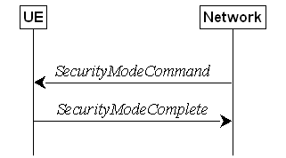
Figure 5.3.4.1-1: Security mode command,
successful
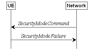
Figure 5.3.4.1-2: Security mode command, failure
The purpose of this procedure is to
activate AS security upon RRC connection establishment.
The network initiates the security mode
command procedure to a UE in RRC_CONNECTED. Moreover, the network applies the
procedure as follows:
- when only SRB1 is established, i.e. prior to
establishment of SRB2, multicast MRBs and/ or DRBs.
The UE shall:
1> derive the KgNB key, as specified
in TS 33.501 [11];
1> derive the KRRCint key associated
with the integrityProtAlgorithm indicated in the SecurityModeCommand
message, as specified in TS 33.501 [11];
1> request lower layers to verify the integrity
protection of the SecurityModeCommand message, using the algorithm
indicated by the integrityProtAlgorithm as included in the SecurityModeCommand
message and the KRRCint key;
1> if the SecurityModeCommand message
passes the integrity protection check:
2> derive the KRRCenc key and the KUPenc
key associated with the cipheringAlgorithm indicated in the SecurityModeCommand
message, as specified in TS 33.501 [11];
2> derive the KUPint key associated
with the integrityProtAlgorithm indicated in the SecurityModeCommand
message, as specified in TS 33.501 [11];
2> configure lower layers to apply SRB
integrity protection using the indicated algorithm and the KRRCint
key immediately, i.e. integrity protection shall be applied to all subsequent
messages received and sent by the UE, including the SecurityModeComplete
message;
2> configure lower layers to apply SRB
ciphering using the indicated algorithm, the KRRCenc keyafter
completing the procedure, i.e. ciphering shall be applied to all subsequent
messages received and sent by the UE, except for the SecurityModeComplete
message which is sent unciphered;
2> consider AS security to be activated;
2> submit the SecurityModeComplete
message to lower layers for transmission, upon which the procedure ends;
1> else:
2> continue using the configuration used prior
to the reception of the SecurityModeCommand message, i.e. neither apply
integrity protection nor ciphering.
2> submit the SecurityModeFailure
message to lower layers for transmission, upon which the procedure ends.
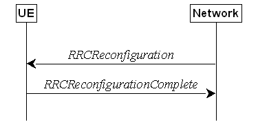
Figure 5.3.5.1-1: RRC reconfiguration, successful
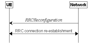
Figure 5.3.5.1-2: RRC reconfiguration, failure
The purpose of this procedure is to modify
an RRC connection, e.g. to establish/modify/release RBs/BH
RLC channels/Uu Relay RLC channels/PC5 Relay RLC channels, to perform reconfiguration with sync, to setup/modify/release
measurements, to add/modify/release SCells and cell groups, to
add/modify/release conditional reconfiguration configuration, to
add/modify/release LTM configuration, and to add/modify/release MP
configuration. As part of the procedure, NAS dedicated information may be
transferred from the Network to the UE.
RRC reconfiguration to perform
reconfiguration with sync includes, but is not limited to, the following cases:
- reconfiguration with sync and security key
refresh, involving RA to the PCell/PSCell, MAC reset, refresh of security and re-establishment of RLC and PDCP
triggered by explicit indicators;
- reconfiguration with sync but without
security key refresh, involving RA to the PCell/PSCell, MAC reset and RLC
re-establishment and PDCP data recovery (for AM DRB or AM MRB) triggered by
explicit indicators;
- reconfiguration with sync for DAPS and
security key refresh, involving RA to the target PCell, establishment of target
MAC, and
- for non-DAPS bearer: refresh of security and
re-establishment of RLC and PDCP triggered by explicit indicators;
- for DAPS bearer: establishment of RLC for
the target PCell, refresh of security and reconfiguration of PDCP to add the
ciphering function, the integrity protection function and ROHC function of the
target PCell;
- for SRB: refresh of security and
establishment of RLC and PDCP for the target PCell;
- reconfiguration with sync for DAPS but
without security key refresh, involving RA to the target PCell, establishment
of target MAC, and
- for non-DAPS bearer: RLC re-establishment
and PDCP data recovery (for AM DRB or AM MRB) triggered by explicit indicators.
- for DAPS bearer: establishment of RLC for
target PCell, reconfiguration of PDCP to add the ciphering function, the
integrity protection function and ROHC function of the target PCell;
- for SRB: establishment of RLC and PDCP for
the target PCell.
- reconfiguration with sync for
direct-to-indirect path switch or indirect-to-indirect path switch, not
involving RA at target side, involving re-establishment of PDCP /PDCP data
recovery (for AM DRB) triggered by explicit indicators;
- reconfiguration with sync for LTM cell switch
(without security key refresh), and
- involving or not involving RA to the target
LTM candidate SpCell according to a network indication;
- MAC reset;
- depending on a network indication, involving
or not involving re-establishment of RLC and PDCP data recovery (for AM DRB).
In (NG)EN-DC and NR-DC, SRB3 can be used
for measurement configuration and reporting, for UE assistance
(re-)configuration and reporting for power savings, for IP address
(re-)configuration and reporting for IAB-nodes, to (re-)configure MAC, RLC, BAP,
physical layer and RLF timers and constants of the SCG configuration, to
reconfigure PDCP for DRBs associated with the S-KgNB or SRB3, to
reconfigure SDAP for DRBs associated with S-KgNB in NGEN-DC and
NR-DC, to add/modify/release conditional PSCell change configuration or
subsequent CPAC configuration, and to add/modify/release the LTM configuration
associated with the SCG (only in NR-DC), provided that the (re-)configuration
does not require any MN involvement, and to transmit RRC messages between the
MN and the UE during fast MCG link recovery. In (NG)EN-DC and NR-DC, only measConfig,
radioBearerConfig, conditionalReconfiguration, ltm-Config (only in
NR-DC), bap-Config, iab-IP-AddressConfigurationList, otherConfig, appLayerMeasConfig and/or secondaryCellGroup are included in RRCReconfiguration
received via SRB3, except when RRCReconfiguration is received within DLInformationTransferMRDC.
When a clause of 5.3.5 is executed due to
an LTM cell switch execution (i.e., as specified in 5.3.5.18.6) or due to a
conditional reconfiguration execution for subsequent CPAC (i.e., as specified
in 5.3.5.13.8), every appearance of "the received" before RRCReconfiguration
message, before a field name, or before an IE name, refers to the RRCReconfiguration
message that the UE applies, as specified in 5.3.5.18.6, 5.3.5.13.8, or the
field or IE in that RRCReconfiguration message.
The Network may initiate the RRC
reconfiguration procedure to a UE in RRC_CONNECTED. The Network applies the
procedure as follows:
- the establishment of RBs (other than SRB1,
that is established during RRC connection establishment) is performed only when
AS security has been activated;
- the establishment of BH RLC Channels for IAB is performed only
when AS security has been activated;
- the configuration of NCR-Fwd is performed only when AS security
has been activated;
- the establishment of Uu Relay RLC channels and PC5 Relay RLC channels (other than SL-RLC0 and SL-RLC1) for L2 U2N
Relay UE is performed only when AS security has been
activated, and the establishment of PC5 Relay RLC
channels for L2 U2N Remote UE (other than SL-RLC0 and
SL-RLC1) is performed only when AS security has been
activated;
- the establishment of PC5 Relay RLC channels
for L2 U2U Relay UE and L2 U2U Remote UE is performed only when AS security has
been activated;
- the addition of Secondary Cell Group and
SCells is performed only when AS security has been activated;
- the reconfigurationWithSync is
included in secondaryCellGroup only when at least one RLC bearer or BH
RLC channel is setup in SCG;
- the reconfigurationWithSync is
included in masterCellGroup only when AS security has been activated,
and SRB2 with at least one DRB or multicast MRB or, for IAB and NCR, SRB2, have been setup and not suspended;
- the conditionalReconfiguration for CPC
is included only when at least one RLC bearer is setup in SCG;
- the conditionalReconfiguration for CHO,
CPA, or subsequent CPAC is included only when AS security has been activated,
and SRB2 with at least one DRB or multicast MRB or, for IAB, SRB2, are setup
and not suspended;
- the addition of indirect path for MP is
performed only when AS security has been activated;
- the ltm-Config for LTM on the MCG is
included only when AS security has been activated, and SRB2 with at least one
DRB are setup and not suspended;
- the ltm-Config for LTM on the SCG is
included only when at least one RLC bearer is setup in SCG.
The UE shall perform the following actions
upon reception of the RRCReconfiguration, upon execution of the
conditional reconfiguration (CHO, CPA, CPC, or subsequent CPAC), or upon
execution of an LTM cell switch:
1> if the RRCReconfiguration is applied
due to a conditional reconfiguration execution upon cell selection performed while
timer T311 was running, as defined in 5.3.7.3:
2> remove all the entries in the condReconfigList
within the MCG and the SCG VarConditionalReconfig except for the entries
in which subsequentCondReconfig is present, if any;
1> if the RRCReconfiguration includes
the daps-SourceRelease:
2> reset the source MAC and release the source
MAC configuration;
2> for each DAPS bearer:
3> release the RLC entity or entities as
specified in TS 38.322 [4], clause 5.1.3, and the associated logical channel
for the source SpCell;
3> reconfigure the PDCP entity to release DAPS
as specified in TS 38.323 [5];
2> for each SRB:
3> release the PDCP entity for the source
SpCell;
3> release the RLC entity as specified in TS
38.322 [4], clause 5.1.3, and the associated logical channel for the source
SpCell;
2> release the physical channel configuration
for the source SpCell;
2> discard the keys used in the source SpCell
(the KgNB key, the KRRCenc key, the KRRCint
key, the KUPint key and the KUPenc key), if any;
1> if the RRCReconfiguration is received
while the timer T348 is running:
2> if the configuration does not exceed UE
temporary capability restriction indicated via musim-CapRestriction
included in the last transmission of UEAssistanceInformation:
3> stop the timer T348;
1> if the RRCReconfiguration is received
via other RAT (i.e., inter-RAT handover to NR):
2> if the RRCReconfiguration does not include the fullConfig and the UE is connected to
5GC (i.e., delta signalling during intra 5GC handover):
3> re-use the source RAT SDAP and PDCP
configurations if available (i.e., current SDAP/PDCP configurations for all RBs
from source E-UTRA RAT prior to the reception of the inter-RAT HO RRCReconfiguration
message);
1> else:
2> if the RRCReconfiguration includes the
fullConfig:
3> perform the full configuration procedure as
specified in 5.3.5.11;
1> if the RRCReconfiguration includes the masterCellGroup:
2> perform the cell group configuration for the
received masterCellGroup according to 5.3.5.5;
1> if the RRCReconfiguration includes the masterKeyUpdate:
2> perform AS security key update procedure as specified in 5.3.5.7;
1> if the RRCReconfiguration includes
the sk-Counter:
2> perform security key update procedure as
specified in 5.3.5.7;
1> if the RRCReconfiguration includes
the secondaryCellGroup:
2> perform the cell group configuration for the
SCG according to 5.3.5.5;
1> if the RRCReconfiguration includes
the mrdc-SecondaryCellGroupConfig:
2> if the mrdc-SecondaryCellGroupConfig
is set to setup:
3> if the mrdc-SecondaryCellGroupConfig
includes mrdc-ReleaseAndAdd:
4> perform MR-DC release as specified in clause
5.3.5.10;
3> if the received mrdc-SecondaryCellGroup
is set to nr-SCG:
4> perform the RRC reconfiguration according to
5.3.5.3 for the RRCReconfiguration message included in nr-SCG;
3> if the received mrdc-SecondaryCellGroup
is set to eutra-SCG:
4> perform the RRC connection reconfiguration as specified in TS 36.331 [10], clause 5.3.5.3 for the RRCConnectionReconfiguration
message included in eutra-SCG;
2> else (mrdc-SecondaryCellGroupConfig
is set to release):
3> perform MR-DC release as specified in clause
5.3.5.10;
NOTE 00: If the UE receives, within an LTM
candidate configuration, an mrdc-SecondaryCellGroupConfig set to release
even if no SCG is currently configured at the UE, the UE does not consider this
as an invalid configuration.
1> if the RRCReconfiguration message
includes the radioBearerConfig:
2> perform the radio bearer configuration
according to 5.3.5.6;
1> if the RRCReconfiguration message
includes the radioBearerConfig2:
2> perform the radio bearer configuration
according to 5.3.5.6;
1> if the RRCReconfiguration message
includes the measConfig:
2> perform the measurement configuration
procedure as specified in 5.5.2;
1> if the RRCReconfiguration message
includes the dedicatedNAS-MessageList:
2> forward each element of the dedicatedNAS-MessageList
to upper layers in the same order as listed;
1> if the RRCReconfiguration message
includes the dedicatedSIB1-Delivery:
2> perform the action upon reception of SIB1
as specified in 5.2.2.4.2;
NOTE 0: If this RRCReconfiguration is
associated to the MCG and includes reconfigurationWithSync in spCellConfig
and dedicatedSIB1-Delivery, the UE initiates (if needed) the request to
acquire required SIBs, according to clause 5.2.2.3.5, only after the random
access procedure or the LTM cell switch execution towards the target SpCell is
completed.
1> if the RRCReconfiguration message
includes the dedicatedSystemInformationDelivery:
2> perform the action upon reception of System
Information as specified in 5.2.2.4;
2> if all the SIB(s) and/or posSIB(s) requested
in DedicatedSIBRequest message have been acquired:
3> stop timer T350, if running;
1> if the RRCReconfiguration message
includes the dedicatedPosSysInfoDelivery:
2> perform the action upon reception of the
contained posSIB(s), as specified in clause 5.2.2.4.16;
2> if all the SIB(s) and/or posSIB(s) requested
in DedicatedSIBRequest message have been acquired:
3> stop timer T350, if running;
1> if the RRCReconfiguration message
includes the otherConfig:
2> perform the other configuration procedure as
specified in 5.3.5.9;
1> if the RRCReconfiguration message
includes the bap-Config:
2> perform the BAP configuration procedure as
specified in 5.3.5.12;
1> if
the RRCReconfiguration message includes the iab-IP-AddressConfigurationList:
2> if iab-IP-AddressToReleaseList is
included:
3> perform release of IP address as specified
in 5.3.5.12a.1.1;
2> if iab-IP-AddressToAddModList is
included:
3> perform IAB IP address addition/update as
specified in 5.3.5.12a.1.2;
1> if the RRCReconfiguration message
includes the conditionalReconfiguration:
2> perform
conditional reconfiguration as specified in 5.3.5.13;
1> if the RRCReconfiguration message
includes the needForGapsConfigNR:
2> if needForGapsConfigNR is set to setup:
3> consider itself to be configured to provide the measurement gap requirement information of
NR target bands;
2> else:
3> consider itself not to be configured to provide the measurement gap requirement information of
NR target bands;
1> if the RRCReconfiguration message
includes the needForGapNCSG-ConfigNR:
2> if needForGapNCSG-ConfigNR is set to setup:
3> consider itself to be configured to provide the measurement gap and NCSG requirement
information of NR target bands;
2> else:
3> consider itself not to be configured to provide the measurement gap and NCSG requirement
information of NR target bands;
1> if the RRCReconfiguration message
includes the needForGapNCSG-ConfigEUTRA:
2> if needForGapNCSG-ConfigEUTRA is set
to setup:
3> consider itself to be configured to provide the measurement gap and NCSG requirement
information of E‑UTRA
target bands;
2> else:
3> consider itself not to be configured to provide the measurement gap and NCSG requirement
information of E‑UTRA target bands;
1> if the RRCReconfiguration message
includes the onDemandSIB-Request:
2> if onDemandSIB-Request is set to setup:
3> consider itself to be configured to request
SIB(s) or posSIB(s) in RRC_CONNECTED in accordance with clause 5.2.2.3.5;
2> else:
3> consider itself not to be configured to
request SIB(s) or posSIB(s) in RRC_CONNECTED in accordance with clause
5.2.2.3.5;
3> stop timer T350, if running;
1> if the RRCReconfiguration message
includes the sl-ConfigDedicatedNR:
2> perform the sidelink dedicated configuration
procedure as specified in 5.3.5.14;
NOTE 0a: If the sl-ConfigDedicatedNR was
received embedded within an E-UTRA RRCConnectionReconfiguration message,
the UE does not build an NR RRCReconfigurationComplete message for the
received sl-ConfigDedicatedNR.
1> if the RRCReconfiguration message
includes the sl-L2RelayUE-Config:
2> perform the L2 U2N or U2U Relay UE
configuration procedure as specified in 5.3.5.15;
1> if the RRCReconfiguration message
includes the sl-L2RemoteUE-Config:
2> perform the L2 U2N or U2U Remote UE
configuration procedure as specified in 5.3.5.16;
1> if the RRCReconfiguration message
includes the dedicatedPagingDelivery:
2> perform the Paging message reception
procedure as specified in 5.3.2.3;
1> if the RRCReconfiguration message
includes the sl-ConfigDedicatedEUTRA-Info:
2> perform related procedures for V2X sidelink
communication in accordance with TS 36.331 [10], clause 5.3.10 and clause
5.5.2;
1> if the RRCReconfiguration message
includes the ul-GapFR2-Config:
2> perform the FR2 UL gap configuration
procedure as specified in 5.3.5.13c;
1> if the RRCReconfiguration message
includes the musim-GapConfig:
2> perform the MUSIM gap configuration
procedure as specified in 5.3.5.9a;
1> if the RRCReconfiguration message
includes the appLayerMeasConfig:
2> for each application layer measurement
configuration with appLayerIdleInactiveConfig configured:
3> if the RPLMN is not included in plmn-IdentityList
in VarAppLayerPLMN-ListConfig:
4> forward the measConfigAppLayerId and
inform upper layers about the release of the application layer measurement
configuration;
4> release the application layer measurement
configuration including its fields in the UE variables VarAppLayerIdleConfig
and VarAppLayerPLMN-ListConfig;
4> discard any application layer measurement
reports which were not yet fully submitted to lower layers for transmission;
4> consider itself not to be configured to send
application layer measurement report for the measConfigAppLayerId;
2> if idleInactiveReportAllowed is
included in the RRCReconfiguration message:
3> if the UE is configured with at least one
application layer measurement configuration with appLayerIdleInactiveConfig
configured:
4> initiate the procedure in 5.7.16.2 after the
RRCReconfigurationComplete has been transmitted;
2> else:
3> for each application layer measurement
configuration with appLayerIdleInactiveConfig configured:
4> forward the measConfigAppLayerId and
inform upper layers about the release of the application layer measurement
configuration;
4> release the application layer measurement
configuration including its fields in the UE variables VarAppLayerIdleConfig
and VarAppLayerPLMN-ListConfig;
4> discard any application layer measurement
reports which were not yet fully submitted to lower layers for transmission;
4> consider itself not to be configured to send
application layer measurement reports for the measConfigAppLayerId;
2> perform the application layer measurement
configuration procedure as specified in 5.3.5.13d;
1> if the RRCReconfiguration message
includes the ue-TxTEG-RequestUL-TDOA-Config:
2> if ue-TxTEG-RequestUL-TDOA-Config is
set to setup:
3> perform the UE positioning assistance
information procedure as specified in 5.7.14;
2> else:
3> release the configuration of UE positioning
assistance information;
1> if the RRCReconfiguration message
includes the aerial-Config:
2> (re)configure the aerial parameters in accordance with the included aerial-Config;
1> if the RRCReconfiguration message
includes the sl-IndirectPathAddChange:
2> perform the SL indirect path specific
configuration procedure as specified in 5.3.5.17.2.2;
1> if the RRCReconfiguration message
includes the n3c-IndirectPathAddChange:
2> perform configuration procedure for the
remote UE part of N3C indirect path as specified in 5.3.5.17.3.2;
1> if the RRCReconfiguration message
includes the n3c-IndirectPathConfigRelay:
2> perform the configuration procedure for the
relay UE part of N3C indirect path as specified in 5.3.5.17.3.3;
1> if the RRCReconfiguration message
includes the ltm-Config:
2> if the ltm-Config is set to setup:
3> perform the LTM configuration procedure as
specified in 5.3.5.18.1;
2> else:
3> perform the LTM configuration release
procedure as specified in clause 5.3.5.18.7;
1> if the RRCReconfiguration message
includes the srs-PosResourceSetLinkedForAggBWList:
2> if srs-PosResourceSetLinkedForAggBWList
is set to setup:
3> perform the SRS for positioning transmission
using bandwidth aggregation provided in configuration srs-PosResourceSetLinkedForAggBW
as specified in TS 38.211 [16];
2> else:
3> release all the configuration of srs-PosResourceSetLinkedForAggBW;
1> set the content of the
RRCReconfigurationComplete message as follows:
2> if the RRCReconfiguration includes
the masterCellGroup containing the reportUplinkTxDirectCurrent:
3> include the uplinkTxDirectCurrentList
for each MCG serving cell with UL;
3> include uplinkDirectCurrentBWP-SUL
for each MCG serving cell configured with SUL carrier, if any, within the uplinkTxDirectCurrentList;
2> if the RRCReconfiguration includes
the masterCellGroup containing the reportUplinkTxDirectCurrentTwoCarrier:
3> include in the uplinkTxDirectCurrentTwoCarrierList
the list of uplink Tx DC locations for the configured intra-band uplink
carrier aggregation in the MCG;
2> if the RRCReconfiguration includes
the masterCellGroup containing the reportUplinkTxDirectCurrentMoreCarrier:
3> include in the uplinkTxDirectCurrentMoreCarrierList
the list of uplink Tx DC locations for the configured intra-band uplink
carrier aggregation in the MCG;
2> if the RRCReconfiguration includes
the secondaryCellGroup containing the reportUplinkTxDirectCurrent:
3> include the uplinkTxDirectCurrentList for
each SCG serving cell with UL;
3> include uplinkDirectCurrentBWP-SUL
for each SCG serving cell configured with SUL carrier, if any, within the uplinkTxDirectCurrentList;
2> if the RRCReconfiguration includes
the secondaryCellGroup containing the reportUplinkTxDirectCurrentTwoCarrier:
3> include in the uplinkTxDirectCurrentTwoCarrierList
the list of uplink Tx DC locations for the configured intra-band uplink
carrier aggregation in the SCG;
2> if the RRCReconfiguration includes
the secondaryCellGroup containing the reportUplinkTxDirectCurrentMoreCarrier:
3> include in the uplinkTxDirectCurrentMoreCarrierList
the list of uplink Tx DC locations for the configured intra-band uplink
carrier aggregation in the SCG;
NOTE 0b: The UE does not expect that the reportUplinkTxDirectCurrentTwoCarrier
or reportUplinkTxDirectCurrentMoreCarrier is received in both masterCellGroup
and in secondaryCellGroup. Network only configures at most one of reportUplinkTxDirectCurrent,
reportUplinkTxDirectCurrentTwoCarrier or reportUplinkTxDirectCurrentMoreCarrier
in one RRC message.
2> if the RRCReconfiguration message
includes the mrdc-SecondaryCellGroupConfig with mrdc-SecondaryCellGroup
set to eutra-SCG:
3> include in the eutra-SCG-Response the
E-UTRA RRCConnectionReconfigurationComplete message in accordance with
TS 36.331 [10] clause 5.3.5.3;
2> if the RRCReconfiguration message
includes the mrdc-SecondaryCellGroupConfig with mrdc-SecondaryCellGroup
set to nr-SCG:
3> include in the nr-SCG-Response the SCG
RRCReconfigurationComplete message;
3> if the RRCReconfiguration message is
applied due to conditional reconfiguration execution and the RRCReconfiguration
message does not include the reconfigurationWithSync in the masterCellGroup:
4> include in the selectedCondRRCReconfig
the condReconfigId for the selected cell of conditional reconfiguration
execution;
4> if a new sk-Counter value has
been selected due to the conditional reconfiguration execution for subsequent
CPAC:
5> include selectedSK-Counter and set
its value to the selected sk-Counter value;
3> if the RRCReconfiguration message is
applied due to conditional reconfiguration execution and
condExecutionCondPSCell is configured for the selected PSCell:
4> include in the selectedPSCellForCHO-WithSCG
and set it to the information of the selected PSCell;
2> if the RRCReconfiguration includes
the reconfigurationWithSync in spCellConfig of an MCG:
3> if the UE has logged measurements available
for NR and if the RPLMN is included in plmn-IdentityList stored in VarLogMeasReport;
or
3> if the UE has logged measurements available
for NR and if the current registered SNPN identity is included in snpn-ConfigID-List
stored in the VarLogMeasReport:
4> include the logMeasAvailable in the
RRCReconfigurationComplete message;
4> if Bluetooth measurement results are
included in the logged measurements the UE has available for NR:
5> include the logMeasAvailableBT in the RRCReconfigurationComplete message;
4> if WLAN measurement results are included in
the logged measurements the UE has available for NR:
5> include the logMeasAvailableWLAN in the RRCReconfigurationComplete message;
3> if the sigLoggedMeasType
in VarLogMeasReport is included; or
3> if the UE supports the override protection of the
signalling based logged MDT for inter-RAT (i.e. LTE to NR), and if the sigLoggedMeasType in VarLogMeasReport of TS 36.331 [10] is included:
4> if T330 timer is running (associated to the
logged measurement configuration for NR or for LTE):
5> set sigLogMeasConfigAvailable to true
in the RRCReconfigurationComplete message;
4> else:
5> if the UE has logged measurements in VarLogMeasReport
or in VarLogMeasReport of TS 36.331 [10]:
6> set sigLogMeasConfigAvailable to false
in the RRCReconfigurationComplete message;
3> if the UE has connection establishment
failure or connection resume failure information available in VarConnEstFailReport
or VarConnEstFailReportList and if the RPLMN is equal to plmn-Identity stored in VarConnEstFailReport
or in at least one of the entries of VarConnEstFailReportList; or
3> if the UE has connection establishment
failure information or connection resume failure information available in VarConnEstFailReport
or VarConnEstFailReportList and if the registered SNPN identity is
equal to snpn-Identity in networkIdentity stored in VarConnEstFailReport
or any entry of VarConnEstFailReportList:
4> include connEstFailInfoAvailable in the RRCReconfigurationComplete
message;
3> if the UE has radio link failure or handover
failure information available in VarRLF-Report and if the RPLMN is
included in plmn-IdentityList stored in VarRLF-Report; or
3> if the UE has radio link failure or handover
failure information available in VarRLF-Report of TS 36.331 [10] and if
the UE is capable of cross-RAT RLF reporting and if the RPLMN is included in
plmn-IdentityList stored in VarRLF-Report of TS 36.331 [10]; or
3> if the UE has radio link failure or handover
failure information available in VarRLF-Report and if the current registered SNPN identity is included in snpn-IdentityList
stored in VarRLF-Report:
4> include rlf-InfoAvailable in the RRCReconfigurationComplete message;
3> if the UE was configured with successHO-Config
when connected to the source PCell:
4> if the applied RRCReconfiguration is
not due to a conditional reconfiguration execution upon cell selection
performed while timer T311 was running, as defined in 5.3.7.3; or
4> if the applied RRCReconfiguration is
not received when T316 was running:
5> perform the actions for the successful
handover report determination as specified in clause 5.7.10.6, upon
successfully completing the Random Access procedure triggered for the reconfigurationWithSync in spCellConfig
of the MCG;
4> if applied RRCReconfiguration is
received when T316 was running:
5> release successHO-Config configured
by the source PCell and thresholdPercentageT304 if configured by the
target PCell;
3> if the UE has successful handover
information available in VarSuccessHO-Report and if the RPLMN is
included in plmn-IdentityList stored in VarSuccessHO-Report; or
3> if the UE has successful handover
information available in VarSuccessHO-Report and if the current registered SNPN identity is included in snpn-IdentityList
stored in the VarSuccessHO-Report:
4> include successHO-InfoAvailable in the RRCReconfigurationComplete message;
3> release successPSCell-Config
configured by the source PCell, if available;
3> if the UE has successful PSCell change or
addition information available in VarSuccessPSCell-Report and if the
RPLMN is included in plmn-IdentityList stored in VarSuccessPSCell-Report;
or
3> if the UE has successful PSCell change or
addition information available in VarSuccessPSCell-Report and if the current registered SNPN identity is included in snpn-IdentityList
stored in the VarSuccessPSCell-Report:
4> include successPSCell-InfoAvailable in the RRCReconfigurationComplete message;
2> if the RRCReconfiguration message was
received via SRB1, but not within mrdc-SecondaryCellGroup or E-UTRA RRCConnectionReconfiguration
or E-UTRA RRCConnectionResume:
3> if the UE is
configured to provide the measurement gap requirement information of NR target
bands:
4> if the RRCReconfiguration message
includes the needForGapsConfigNR; or
4> if the NeedForGapsInfoNR information
is changed compared to last time the UE reported this information; or
4> if the RRCReconfiguration message
includes the needForInterruptionConfigNR and set it to enabled;
or
4> if the needForInterruptionConfigNR is
enabled and the NeedForInterruptionInfoNR information is changed
compared to last time the UE reported this information:
5> include the NeedForGapsInfoNR and set
the contents as follows:
6> include intraFreq-needForGap and set
the gap requirement information of intra-frequency measurement for each NR
serving cell;
6> if requestedTargetBandFilterNR is
configured:
7> for each supported NR band that is also
included in requestedTargetBandFilterNR, include an entry in interFreq-needForGap
and set the gap requirement information for that band;
6> else:
7> include an entry in interFreq-needForGap
and set the corresponding gap requirement information for each supported NR
band;
5> if the needForInterruptionConfigNR is
enabled:
6> include the needForInterruptionInfoNR
and set the contents as follows:
7> include intraFreq-needForInterruption
with the same number of entries, and listed in the same order, as in intraFreq-needForGap;
7> for each entry in intraFreq-needForInterruption:
8> include interruptionIndication and
set the interruption requirement information if the corresponding entry in intraFreq-needForGap
is set to no-gap;
7> include interFreq-needForInterruption with
the same number of entries, and listed in the same order, as in interFreq-needForGap;
7> for each entry in interFreq-needForInterruption:
8> include interruptionIndication and
set the interruption requirement information if the corresponding entry in interFreq-needForGap
is set to no-gap;
3> if the UE is
configured to provide the measurement gap and NCSG requirement information of
NR target bands:
4> if the RRCReconfiguration message
includes the needForGapNCSG-ConfigNR; or
4> if the needForGapNCSG-InfoNR
information is changed compared to last time the UE reported this information:
5> include the NeedForGapNCSG-InfoNR and
set the contents as follows:
6> include intraFreq-needForNCSG and set
the gap and NCSG requirement information of intra-frequency measurement for
each NR serving cell;
6> if requestedTargetBandFilterNCSG-NR
is configured:
7> for each supported NR band included in requestedTargetBandFilterNCSG-NR,
include an entry in interFreq-needForNCSG and set the NCSG requirement
information for that band;
6> else:
7> include an entry for each supported NR band
in interFreq-needForNCSG and set the corresponding NCSG requirement
information;
3> if the UE is
configured to provide the measurement gap and NCSG requirement information of E‑UTRA
target bands:
4> if the RRCReconfiguration message
includes the needForGapNCSG-ConfigEUTRA; or
4> if the needForGapNCSG-InfoEUTRA
information is changed compared to last time the UE reported this information:
5> include the NeedForGapNCSG-InfoEUTRA
and set the contents as follows:
6> if requestedTargetBandFilterNCSG-EUTRA
is configured, for each supported E-UTRA band included in requestedTargetBandFilterNCSG-EUTRA,
include an entry in needForNCSG-EUTRA and set the NCSG requirement
information for that band; otherwise, include an entry for each supported
E-UTRA band in needForNCSG-EUTRA and set the corresponding NCSG
requirement information;
2> if the UE has (updated) flight path
information available:
3> if the UE had not provided a flight path information since last entering
RRC_CONNECTED state; or
3> if at least one waypoint or a timestamp corresponding to a waypoint
location that was not previously provided since last entering RRC_CONNECTED state is available; or
3> if at least one upcoming waypoint or a timestamp corresponding to a waypoint location that was previously provided since last
entering RRC_CONNECTED state is to be removed; or
3> if flightPathUpdateDistanceThr is configured and, for at least one waypoint, the 3D distance
between the previously provided location and the new location is more than the
distance threshold configured by flightPathUpdateDistanceThr; or
3> if flightPathUpdateTimeThr
is configured and, for at least one waypoint, the
time difference between the previously provided timestamp and the new
timestamp, if available, is more than the time threshold configured by flightPathUpdateTimeThr:
4> include flightPathInfoAvailable;
NOTE 0c: If neither flightPathUpdateDistanceThr
nor flightPathUpdateTimeThr is configured, it is up to UE implementation
whether to include flightPathInfoAvailable when updated flight path
information is available.
2> if the UE has at least one stored
application layer measurement configuration with appLayerIdleInactiveConfig
configured which has not been successfully transmitted since entering
RRC_CONNECTED state:
3> include measConfigReportAppLayerAvailable;
2> if this RRCReconfiguration message is
applied due to an LTM cell switch execution procedure according to clause
5.3.5.18.6:
3> include in the appliedLTM-CandidateId
the LTM-CandidateId of the applied LTM candidate configuration;
1> if the UE is configured with E-UTRA nr-SecondaryCellGroupConfig
(UE in (NG)EN-DC):
2> if the RRCReconfiguration message was
received via E-UTRA SRB1 as specified in TS 36.331 [10]; or
2> if the RRCReconfiguration message was
received via E-UTRA RRC message RRCConnectionReconfiguration within MobilityFromNRCommand
(handover from NR standalone to (NG)EN-DC);
3> if the RRCReconfiguration
is applied due to a conditional reconfiguration execution for CPC which is
configured via conditionalReconfiguration contained in nr-SecondaryCellGroupConfig
specified in TS 36.331 [10]:
4> submit the RRCReconfigurationComplete
message via the E-UTRA MCG embedded in E-UTRA RRC message ULInformationTransferMRDC
as specified in TS 36.331 [10], clause 5.6.2a.
3> else if the RRCReconfiguration
message was included in E-UTRA RRCConnectionResume message:
4> submit the RRCReconfigurationComplete
message via E-UTRA embedded in E-UTRA RRC message RRCConnectionResumeComplete
as specified in TS 36.331 [10], clause 5.3.3.4a;
3> else:
4> submit the RRCReconfigurationComplete
via E-UTRA embedded in E-UTRA RRC message RRCConnectionReconfigurationComplete
as specified in TS 36.331 [10], clause 5.3.5.3/5.3.5.4/5.4.2.3;
3> if the scg-State is not included in
the E-UTRA message (RRCConnectionReconfiguration or RRCConnectionResume)
containing the RRCReconfiguration message:
4> perform SCG activation as specified in
5.3.5.13a;
4> if reconfigurationWithSync was
included in spCellConfig of an SCG:
5> initiate the Random Access procedure on the
PSCell, as specified in TS 38.321 [3];
4> else if the SCG was deactivated before the
reception of the E-UTRA RRC message containing the RRCReconfiguration
message:
5> if bfd-and-RLM was not configured to true
before the reception of the E-UTRA RRCConnectionReconfiguration or RRCConnectionResume
message containing the RRCReconfiguration message or if lower layers indicate
that a Random Access procedure is needed for SCG activation:
6> initiate the Random Access procedure on the
SpCell, as specified in TS 38.321 [3];
5> else the procedure ends;
4> else the procedure ends;
3> else:
4> perform SCG deactivation as specified in 5.3.5.13b;
4> the procedure ends;
2> if the RRCReconfiguration message was
received within nr-SecondaryCellGroupConfig in RRCConnectionReconfiguration
message received via SRB3 within DLInformationTransferMRDC:
3> submit the RRCReconfigurationComplete
via E-UTRA embedded in E-UTRA RRC message RRCConnectionReconfigurationComplete
as specified in TS 36.331 [10], clause 5.3.5.3/5.3.5.4;
3> if the scg-State is not included in
the RRCConnectionReconfiguration:
4> if reconfigurationWithSync was
included in spCellConfig of an SCG:
5> initiate the Random Access procedure on the
SpCell, as specified in TS 38.321 [3];
4> else the procedure ends;
3> else:
4> perform SCG deactivation as specified in
5.3.5.13b;
4> the procedure ends;
NOTE 1: The order the UE sends the RRCConnectionReconfigurationComplete
message and performs the Random Access procedure towards the SCG is left to UE
implementation.
2> else (RRCReconfiguration was received
via SRB3) but not within DLInformationTransferMRDC:
3> submit the RRCReconfigurationComplete
message via SRB3 to lower layers for transmission using the new configuration;
NOTE 2: In (NG)EN-DC and NR-DC, in the case RRCReconfiguration
is received via SRB1 or within DLInformationTransferMRDC via SRB3, the
random access is triggered by RRC layer itself as there is not necessarily
other UL transmission. In the case RRCReconfiguration is received via
SRB3 but not within DLInformationTransferMRDC, the random access is
triggered by the MAC layer due to arrival of RRCReconfigurationComplete.
1> else if the RRCReconfiguration
message was received via SRB1 within the nr-SCG within mrdc-SecondaryCellGroup
(UE in NR-DC, mrdc-SecondaryCellGroup was received in RRCReconfiguration
or RRCResume via SRB1):
2> if the RRCReconfiguration is applied
due to a conditional reconfiguration execution for CPC or subsequent CPAC which
is configured via conditionalReconfiguration contained in nr-SCG
within mrdc-SecondaryCellGroup; or
2> if the RRCReconfiguration is applied
due to an LTM cell switch execution:
3> submit the RRCReconfigurationComplete
message via SRB1 embedded in NR RRC message ULInformationTransferMRDC
as specified in clause 5.7.2a.3.
2> if the scg-State is not included in
the RRCReconfiguration or RRCResume message containing the RRCReconfiguration
message:
3> perform SCG activation as specified in
5.3.5.13a;
3> if reconfigurationWithSync was
included in spCellConfig in nr-SCG:
4> if the RRCReconfiguration message is
not applied due to an LTM cell switch execution for which lower layer indicate
to skip the Random Access procedure:
5> initiate the Random Access procedure on the PSCell,
as specified in TS 38.321 [3];
4> if the UE was configured with successPSCell-Config
when connected to the source PSCell (for PSCell change) or to the PCell (for
PSCell addition or change):
5> perform the actions for the successful
PSCell change or addition report determination as specified in clause 5.7.10.7,
upon successfully completing the Random Access procedure triggered for the reconfigurationWithSync in spCellConfig
of the SCG;
3> else if the SCG was deactivated before the
reception of the NR RRC message containing the RRCReconfiguration
message:
4> if bfd-and-RLM was not configured to true
before the reception of the RRCReconfiguration or RRCResume
message containing the RRCReconfiguration message; or
4> if lower layers indicate that a Random
Access procedure is needed for SCG activation:
5> initiate the Random Access procedure on the
PSCell, as specified in TS 38.321 [3];
4> else the procedure ends;
3> else the procedure ends;
2> else
3> perform SCG deactivation as specified in 5.3.5.13b;
3> the procedure ends;
NOTE 2a: The order in which the UE sends the RRCReconfigurationComplete
message and performs the Random Access procedure towards the SCG is left to UE
implementation.
1> else if the RRCReconfiguration
message was received via SRB3 (UE in NR-DC):
2> if the RRCReconfiguration message was
received within DLInformationTransferMRDC:
3> if the RRCReconfiguration message was
received within the nr-SCG within mrdc-SecondaryCellGroup (NR SCG
RRC Reconfiguration):
4> if the scg-State is not included in
the RRCReconfiguration message containing the RRCReconfiguration
message:
5> if reconfigurationWithSync was
included in spCellConfig in nr-SCG:
6> initiate the Random Access procedure on the
PSCell, as specified in TS 38.321 [3];
6> if the UE was configured with successPSCell-Config
when connected to the source PSCell (for PSCell change) or to the PCell (for
PSCell addition or change):
7> perform the actions for the successful
PSCell change report determination as specified in clause 5.7.10.7, upon
successfully completing the Random Access procedure triggered for the reconfigurationWithSync in spCellConfig
of the SCG;
5> else:
6> the procedure ends;
4> else:
5> perform SCG deactivation as specified in
5.3.5.13b;
5> the procedure ends;
3> else:
4> if the RRCReconfiguration does not
include the mrdc-SecondaryCellGroupConfig:
5> if the RRCReconfiguration includes
the scg-State:
6> perform SCG deactivation as specified in
5.3.5.13b;
4> submit the RRCReconfigurationComplete
message via SRB1 to lower layers for transmission using the new configuration;
2> else:
3> if the RRCReconfiguration
includes the reconfigurationWithSync in spCellConfig for the SCG;
and
3> if the UE was configured with successPSCell-Config
when connected to the source PSCell (for PSCell change):
4> perform the actions for the successful
PSCell change report determination as specified in clause 5.7.10.7, upon
successfully completing the Random Access procedure triggered for the reconfigurationWithSync in spCellConfig
of the SCG;
3> if the UE has successful PSCell change or
addition information available in VarSuccessPSCell-Report and if the
RPLMN is included in plmn-IdentityList stored in VarSuccessPSCell-Report;
or
3> if the UE has successful PSCell change or
addition information available in VarSuccessPSCell-Report and if the current registered SNPN identity is included in snpn-IdentityList
stored in the VarSuccessPSCell-Report:
4> include successPSCell-InfoAvailable in the RRCReconfigurationComplete message;
3> submit the RRCReconfigurationComplete
message via SRB3 to lower layers for transmission using the new configuration;
1> else (RRCReconfiguration was
received via SRB1):
2> if the UE is in NR-DC and;
2> if the RRCReconfiguration does not
include the mrdc-SecondaryCellGroupConfig:
3> if the RRCReconfiguration includes
the scg-State:
4> perform SCG deactivation as specified in
5.3.5.13b;
3> else:
4> perform SCG activation without SN message as
specified in 5.3.5.13b1;
2> if the reconfigurationWithSync was
included in spCellConfig of an MCG:
3> if ta-Report or ta-ReportATG is configured with value enabled and
the UE supports TA reporting:
4> indicate TA report
initiation to lower layers;
2> submit the RRCReconfigurationComplete
message via SRB1 to lower layers for transmission using the new configuration;
2> if this is the first RRCReconfiguration
message after successful completion of the RRC re-establishment procedure:
3> resume SRB2, SRB4, DRBs, multicast MRB, and
BH RLC channels for IAB-MT, and Uu Relay RLC channels for L2 U2N Relay UE, that
are suspended;
1> if sl-IndirectPathAddChange was
included in RRCReconfiguration message:
2> if SRB1 is configured as split SRB and pdcp-Duplication
is configured:
3> when successfully sending RRCReconfigurationComplete
message via SL indirect path (i.e., PC5 RLC acknowledgement is received from
target L2 U2N Relay UE):
4> stop timer T421;
2> else (i.e. split SRB1 with duplication is
not configured):
3> when receiving RRCReconfigurationCompleteSidelink
message from target L2 U2N Relay UE:
4> stop timer T421;
1> if reconfigurationWithSync was
included in spCellConfig of an MCG or SCG and when MAC of an NR cell
group successfully completes a Random Access procedure triggered above; or,
1> if sl-PathSwitchConfig was included in reconfigurationWithSync included in spCellConfig of an MCG, and when successfully sending RRCReconfigurationComplete message
(i.e., PC5 RLC acknowledgement is received from target L2 U2N Relay UE); or,
1> if rach-LessHO
was included in reconfigurationWithSync included in spCellConfig
of an MCG, and upon indication from lower layers that the RACH-less handover
has been successfully completed; or,
1> if reconfigurationWithSync was included in spCellConfig of an MCG or SCG and the RRCReconfiguration
message is applied due to an LTM cell switch execution and upon an indication
from lower layer that the LTM cell switch execution has been successfully
completed:
2> stop timer T304 for that cell group if
running;
2> if rach-LessHO was included in reconfigurationWithSync
included in spCellConfig of an MCG, and upon indication from lower
layers that the RACH-less handover has been successfully completed; or,
2> if reconfigurationWithSync was included in spCellConfig of an MCG or SCG and the RRCReconfiguration
message is applied due to an LTM cell switch execution and upon an indication
from lower layer that the LTM cell switch execution has been successfully
completed:
3> release dedicated preambles provided in rach-ConfigDedicated
within reconfigurationWithSync, if configured;
3> release dedicated msgA PUSCH resources
provided in rach-ConfigDedicated within reconfigurationWithSync, if configured;
2> if sl-PathSwitchConfig was included
in reconfigurationWithSync:
3> if the sl-IndirectPathMaintain is not included in reconfigurationWithSync:
4> stop timer T420;
4> release all radio
resources, including release of the RLC entities and the MAC configuration at
the source side;
4> reset MAC used in the source cell;
3> else (sl-IndirectPathMaintain is included):
4> release radio resources on the direct path,
including release of the RLC entities and the MAC configuration;
4> reset MAC used in the source cell;
2> if rach-LessHO was included in reconfigurationWithSync
and cg-RRC-Configuration was configured:
3> release the uplink grant configured for
RACH-less handover;
NOTE 2b: PDCP and SDAP configured by the source
prior to the path switch that are reconfigured and re-used by target when delta
signalling is used, are not released as part of this procedure.
2> stop timer T310 for source SpCell if
running;
2> apply the parts of the CSI reporting
configuration, the scheduling request configuration and the sounding RS
configuration that do not require the UE to know the SFN of the respective
target SpCell, if any;
2> apply the parts of the measurement and the
radio resource configuration that require the UE to know the SFN of the
respective target SpCell (e.g. measurement gaps, periodic CQI reporting,
scheduling request configuration, sounding RS configuration), if any, upon
acquiring the SFN of that target SpCell;
2> for each DRB configured as DAPS bearer,
request uplink data switching to the PDCP entity, as specified in TS 38.323
[5];
2> if the reconfigurationWithSync was
included in spCellConfig of an MCG:
3> if T390 is running:
4> stop timer T390 for all access categories;
4> perform the actions as specified in
5.3.14.4.
3> if T350 is running:
4> stop timer T350;
3> if RRCReconfiguration does not
include dedicatedSIB1-Delivery and
3> if the active downlink BWP, which is
indicated by the firstActiveDownlinkBWP-Id for the target SpCell of the
MCG, has a common search space configured by searchSpaceSIB1:
4> acquire the SIB1, which is scheduled
as specified in TS 38.213 [13], of the target SpCell of the MCG;
4> upon acquiring SIB1, perform the
actions specified in clause 5.2.2.4.2;
2> if the RRCReconfiguration message is
applied due to a conditional reconfiguration execution and the RRCReconfiguration
message is contained in an entry in MCG VarConditionalReconfig that
includes the subsequentCondReconfig:
3> for each entry in the condReconfigList
within the MCG VarConditionalReconfig:
4> if there is an entry in condExecutionCondToAddModList
within the subsequentCondReconfig that has subsequentCondReconfigId matching
the condReconfigId in the entry of the condReconfigList:
5> if subsequentCondExecutionCondSCG is
included in the entry of the condExecutionCondToAddModList:
6> store in the condExecutionCondSCG in
the entry of the condReconfigList the value of subsequentCondExecutionCondSCG
in the entry of the condExecutionCondToAddModList;
2> if the RRCReconfiguration message is
applied due to a conditional reconfiguration execution and the RRCReconfiguration
message is contained in an entry in SCG VarConditionalReconfig that
includes the subsequentCondReconfig:
3> for each entry in the condReconfigList
within the SCG VarConditionalReconfig:
4> if there is an entry in condExecutionCondToAddModList
within the subsequentCondReconfig that has subsequentCondReconfigId
matching the condReconfigId in the entry of the condReconfigList:
5> if subsequentCondExecutionCond is
included in the entry of the condExecutionCondToAddModList:
6> store in the condExecutionCond in the
entry of the condReconfigList the value of subsequentCondExecutionCond
in the entry of the condExecutionCondToAddModList;
2> if the reconfigurationWithSync was
included in spCellConfig of an MCG; or
2> if the reconfigurationWithSync was
included in spCellConfig of an SCG and the CPA, CPC, or subsequent CPAC
was configured:
3> remove all the entries in the condReconfigList
within the MCG and the SCG VarConditionalReconfig except for the entries
in which subsequentCondReconfig is present, if any;
3> remove all the entries within VarConditionalReconfiguration
as specified in TS 36.331 [10], clause 5.3.5.9.6, if any;
3> for each measId of the MCG measConfig,
if configured, and for each measId of the SCG measConfig, if
configured, if the associated reportConfig has a reportType set
to condTriggerConfig:
4> if the reportConfigId is not
associated with any measId indicated by the condExecutionCond or
the condExecutionCondSCG in an entry of condReconfigList in VarConditionalReconfig
in which subsequentCondReconfig is included:
5> remove the entry with the matching reportConfigId
from the reportConfigList within the VarMeasConfig;
4> if the associated measObjectId is
only associated to a reportConfig with reportType set to condTriggerConfig;
and
4> if the measObjectId is not associated
with any measId indicated by the condExecutionCond or the condExecutionCondSCG
in an entry of condReconfigList in VarConditionalReconfig in
which subsequentCondReconfig is included:
5> remove the entry with the matching measObjectId
from the measObjectList within the VarMeasConfig;
4> remove the entry with the matching measId
from the measIdList within the VarMeasConfig;
2> if reconfigurationWithSync was
included in masterCellGroup or secondaryCellGroup:
3> if the UE initiated transmission of a UEAssistanceInformation
message for the corresponding cell group during the last 1 second, and the UE
is still configured to provide the concerned UE assistance information for the corresponding cell group; or
3> if the RRCReconfiguration message is
applied due to a conditional reconfiguration execution or an LTM cell switch
procedure, and the UE is configured to provide UE assistance information for
the corresponding cell group, and the UE has initiated transmission of a UEAssistanceInformation
message for the corresponding cell group since it was configured to do so in
accordance with 5.7.4.2:
4> initiate transmission of a UEAssistanceInformation
message for the corresponding cell group in accordance with clause 5.7.4.3 to provide the concerned UE assistance information;
4> start or restart the prohibit timer (if
exists) associated with the concerned UE assistance information with the timer value
set to the value in corresponding configuration;
4> start or restart the leave without response
timer (if exists) with the
timer value set to the value in the musim-LeaveAssistanceConfig or the
wait timer (if exists) with the
timer value set to the value in musim-CapabilityRestrictionConfig;
3> if SIB12 is provided by the target
PCell, and the UE initiated transmission of a SidelinkUEInformationNR
message indicating a change of NR sidelink communication/discovery related
parameters relevant in target PCell (i.e. change of sl-RxInterestedFreqList
or sl-TxResourceReqList) during the last 1 second preceding reception of
the RRCReconfiguration message including reconfigurationWithSync in
spCellConfig of an MCG; or
3> if the RRCReconfiguration message is
applied due to a conditional reconfiguration execution and the UE is capable of
NR sidelink communication/discovery and SIB12 is provided by the target
PCell, and the UE has initiated transmission of a SidelinkUEInformationNR
message since it was configured to do so in accordance with 5.8.3.2:
4> initiate transmission of the SidelinkUEInformationNR
message in accordance with 5.8.3.3;
3> if any application layer measurement report
container has been received from upper layers for which the successful
transmission of the MeasurementReportAppLayer message or at least one
segment of the message via SRB4 (if reconfigurationWithSync was included
in masterCellGroup) or SRB5 (if reconfigurationWithSync was
included in secondaryCellGroup) has not been confirmed by lower layers:
4> if RRC segmentation was used for the MeasurementReportAppLayer
message:
5> if RRC segmentation is enabled based on the
field rrc-SegAllowedSRB4 or rrc-SegAllowedSRB5 for the reportingSRB
(or SRB4 if reportingSRB is not configured):
6> re-submit all segments of the MeasurementReportAppLayer
message to lower layers for transmission via the reportingSRB (or SRB4
if reportingSRB is not configured);
5> else:
6> discard all segments of the MeasurementReportAppLayer
message;
4> else:
5> re-submit the MeasurementReportAppLayer
message to lower layers for transmission via the reportingSRB (or SRB4
if reportingSRB is not configured);
2> if reconfigurationWithSync
was included in masterCellGroup and SRB4 is configured in the target
cell:
3> for each application layer measurement
configuration in the UE:
4> if the RRCReconfiguration message is
applied due to a conditional reconfiguration execution,
if transmissionOfSessionStartStop is set to true
for the application layer measurement configuration and if the session status
has changed since the UE was configured with the conditional reconfiguration:
5> initiate transmission of a MeasurementReportAppLayer
message including appLayerSessionStatus, via SRB4 for the application
layer measurement in accordance with 5.7.16.2;
2> if reconfigurationWithSync was
included in masterCellGroup and the target cell provides SIB21 or
provides SIB1 including nonServingCellMII:
3> if the UE initiated transmission of an MBSInterestIndication
message during the last 1 second preceding reception of this RRCReconfiguration
message; or
3> if the RRCReconfiguration message is
applied due to a conditional reconfiguration execution, and the UE has
initiated transmission of an MBSInterestIndication message after having
received this RRCReconfiguration message:
4> initiate transmission of an MBSInterestIndication
message in accordance with clause 5.9.4;
2> the procedure ends.
NOTE 3: The UE is only required to acquire broadcasted SIB1
if the UE can acquire it without disrupting unicast or MBS multicast data
reception, i.e. the broadcast and unicast/MBS multicast beams are quasi
co-located.
NOTE 4: The UE sets the content of UEAssistanceInformation
according to latest configuration (i.e. the configuration after applying the RRCReconfiguration
message) and latest UE preference. The UE may include more than the concerned
UE assistance information within the UEAssistanceInformation according
to 5.7.4.2. Therefore, the
content of UEAssistanceInformation message might not be the same as the
content of the previous UEAssistanceInformation message.
The UE shall:
1> as a result of SCG release triggered by
E-UTRA (i.e. (NG)EN-DC case) or NR (i.e. NR-DC case):
2> reset SCG MAC, if configured;
2> for each RLC bearer that is part of the SCG
configuration:
3> perform RLC bearer release procedure as
specified in 5.3.5.5.3;
2> for each BH RLC channel that is part of the
SCG configuration:
3> perform BH RLC channel release procedure as
specified in 5.3.5.5.10;
2> release the SCG configuration;
2> for each application layer measurement
configuration that is part of the SCG configuration:
3> forward the measConfigAppLayerId and inform
upper layers about the release of the application layer measurement
configuration;
3> release the application layer measurement
configuration including its fields in the UE variables VarAppLayerIdleConfig
and VarAppLayerPLMN-ListConfig, if stored;
3> discard any application layer measurement
reports which were not yet fully submitted to lower layers for transmission;
3> consider itself not to be configured to send
application layer measurement reports for the measConfigAppLayerId;
2> discard any application layer measurement
reports which were configured to be reported via SRB5 and which were not yet
fully submitted to lower layers for transmission;
2> remove all the entries within the SCG VarConditionalReconfig,
if any;
2> if SCG release was triggered by NR (i.e.
NR-DC case):
3> remove all the entries in the condReconfigList
within the MCG VarConditionalReconfig for which subsequentCondReconfig
is not present and the RRCReconfiguration within condRRCReconfig
does not include the masterCellGroup with reconfigurationWithSync,
if any;
3> remove the servingSecurityCellSetId
within the VarServingSecurityCellSetID, if any;
3> for each entry in the condReconfigList within the MCG VarConditionalReconfig for which subsequentCondReconfig
is present:
4> remove the condExecutionCondSCG, if
stored;
2> else (i.e. EN-DC case):
3> perform VarConditionalReconfiguration
CPC removal as specified in TS 36.331 [10] clause 5.3.5.9.7;
2> stop timer T310 for the corresponding
SpCell, if running;
2> stop timer T312 for the corresponding
SpCell, if running;
2> stop timer T304 for the corresponding
SpCell, if running.
NOTE: Release of cell group means only
release of the lower layer configuration of the cell group but the RadioBearerConfig
may not be released.
The network configures the UE with Master
Cell Group (MCG), and zero or one Secondary Cell Group (SCG). In (NG)EN-DC, the
MCG is configured as specified in TS 36.331 [10], and for NE-DC, the SCG is
configured as specified in TS 36.331 [10]. The network provides the
configuration parameters for a cell group in the CellGroupConfig IE.
The UE performs the following actions based
on a received CellGroupConfig IE:
1> if the CellGroupConfig contains the spCellConfig
with reconfigurationWithSync:
2> perform Reconfiguration with sync according
to 5.3.5.5.2;
2> resume all suspended radio bearers except
the SRBs for the source cell group, and resume SCG transmission for all radio
bearers, and resume BH RLC channels and resume SCG transmission for BH RLC
channels for IAB-MT, if suspended;
NOTE 1: If the SCG is deactivated, resuming SCG
transmission for all radio bearers does not imply that PDCP PDUs can be
transmitted or received on SCG RLC bearers.
1> if the CellGroupConfig contains the rlc-BearerToReleaseList
or rlc-BearerToReleaseListExt:
2> perform RLC bearer release as specified in
5.3.5.5.3;
1> if the CellGroupConfig contains the rlc-BearerToAddModList:
2> perform the RLC bearer addition/modification
as specified in 5.3.5.5.4;
1> if the CellGroupConfig contains the mac-CellGroupConfig:
2> configure the MAC entity of this cell group
as specified in 5.3.5.5.5;
1> if the CellGroupConfig contains the sCellToReleaseList:
2> perform SCell release as specified in
5.3.5.5.8;
1> if the CellGroupConfig contains the spCellConfig:
2> configure the SpCell as specified in
5.3.5.5.7;
1> if the CellGroupConfig contains the sCellToAddModList:
2> perform SCell addition/modification as
specified in 5.3.5.5.9;
1> if the CellGroupConfig contains the bh-RLC-ChannelToReleaseList:
2> perform BH RLC channel release as specified
in 5.3.5.5.10;
1> if the CellGroupConfig contains the bh-RLC-ChannelToAddModList:
2> perform the BH RLC channel
addition/modification as specified in 5.3.5.5.11;
1> if the CellGroupConfig
contains the uu-RelayRLC-ChannelToReleaseList:
2> perform Uu Relay RLC channel release as
specified in 5.3.5.5.12;
1> if the CellGroupConfig contains the uu-RelayRLC-ChannelToAddModList:
2> perform the Uu Relay RLC channel
addition/modification as specified in 5.3.5.5.13;
1> if the CellGroupConfig contains the ncr-FwdConfig:
2> perform the NCR-Fwd configuration as
specified in 5.3.5.5.14;
1> if the CellGroupConfig contains the autonomousDenialParameters:
2> consider itself to be allowed to deny any
transmission in a particular UL slot if during the number of slots indicated by
autonomousDenialValidity, preceding and including this particular slot,
it autonomously denied fewer UL slots than indicated by autonomousDenialSlots
within the same cell group;
NOTE 2: When counting the
number of denied UL slots, the UE sums up the denied UL slots across all
serving cells within the same cell group. When counting the number of slots
indicated by autonomousDenialValidity, the UE sums up the UL slots
across all serving cells within the same cell group.
NOTE 3: When multiple denied UL slots across all
serving cells partially or fully overlap in the time domain, the number of
denied UL slots across all serving cells is counted as one denied UL slot,
based on the longest slot.
The UE shall perform the following actions
to execute a reconfiguration with sync.
1> if the AS security is not activated, perform
the actions upon going to RRC_IDLE as specified in 5.3.11 with the release
cause 'other' upon which the procedure ends;
1> stop timer T430 if running;
1> if no DAPS bearer is configured:
2> stop timer T310 for the corresponding
SpCell, if running;
1> if
this procedure is executed for the MCG:
2> if timer T316 is running;
3> stop timer T316;
3> if the UE supports RLF-Report
for fast MCG recovery procedure as specified in TS 38.306
[26]:
4> set the elapsedTimeT316 in the VarRLF-Report
to the value of the elapsed time of the timer T316;
4> set the pSCellId in the VarRLF-Report
to the global cell identity of the PSCell, if available, otherwise to the
physical cell identity and carrier frequency of the PSCell;
3> else:
4> clear the information included in VarRLF-Report,
if any;
2> resume MCG transmission, if suspended.
1> stop timer T312 for the corresponding
SpCell, if running;
1> if sl-PathSwitchConfig is included:
2> apply the value of the newUE-Identity
as the C-RNTI;
2> if sl-IndirectPathMaintain is
not included in reconfigurationWithSync:
3> if the UE is L2 U2N remote UE at source side:
4> indicate to upper layer to trigger PC5
unicast link release with the source L2 U2N Relay UE;
3> consider the target L2 U2N Relay UE to be
the one indicated by the targetRelayUE-Identity in the sl-PathSwitchConfig;
3> start timer T420 for the corresponding
target L2 U2N Relay UE with the timer value set to t420, as included in
the sl-PathSwitchConfig;
3> indicate to upper layer (to trigger the PC5
unicast link establishment) with the target L2 U2N Relay UE indicated by the targetRelayUE-Identity;
3> apply the default configuration of SL-RLC1 as defined in 9.2.4 for
SRB1;
2> else:
3> consider the connected L2 U2N Relay UE on
the indirect path as the target L2 U2N relay UE, and maintain the PC5
connection with the L2 U2N Relay UE;
1> else (sl-PathSwitchConfig is not included):
2> if this procedure is executed for the MCG or
if this procedure is executed for an SCG not indicated as deactivated in the
E-UTRA or NR RRC message in which the RRCReconfiguration message is
embedded:
3> start timer T304 for the corresponding
SpCell with the timer value set to t304, as included in the reconfigurationWithSync;
2> if the frequencyInfoDL is included:
3> consider the target SpCell to be one on the
SSB frequency indicated by the frequencyInfoDL with a physical cell
identity indicated by the physCellId;
2> else:
3> consider the target SpCell to be one on the
SSB frequency of the source SpCell with a physical cell identity indicated by
the physCellId;
2> if this procedure is performed due to an LTM
cell switch execution:
3> start synchronising to the DL of the
indicated LTM candidate cell, if no DL synchronization for the indicated LTM
candidate cell has been already acquired;
2> else:
3> start synchronising to the DL of the target
SpCell;
2> apply the specified BCCH configuration
defined in 9.1.1.1 for the target SpCell;
2> acquire the MIB of the target SpCell,
which is scheduled as specified in TS 38.213 [13];
2> if NTN-Config is configured for the
target cell:
3> start timer T430 with the timer value set to
ntn-UlSyncValidityDuration from the subframe indicated by epochTime,
according to the target cell NTN-Config;
NOTE 1: The UE should perform the reconfiguration
with sync as soon as possible following the reception of the RRC message triggering
the reconfiguration with sync, which could be before confirming successful
reception (HARQ and ARQ) of this message.
NOTE 2: The UE may omit reading the MIB if
the UE already has the required timing information, or the timing information
is not needed for random access, or if not needed for RACH-less initial UL
transmission.
NOTE 2a: A UE with DAPS bearer does not monitor
for system information updates in the source PCell.
2> If any DAPS bearer is configured:
3> create a MAC entity for the target cell
group with the same configuration as the MAC entity for the source cell group;
3> for each DAPS bearer:
4> establish an RLC entity or entities for the
target cell group, with the same configurations as for the source cell group;
4> establish the logical channel for the target
cell group, with the same configurations as for the source cell group;
NOTE 2b: In order to understand if a DAPS bearer
is configured, the UE needs to check the presence of the field daps-Config
within the RadioBearerConfig IE received in radioBearerConfig or radioBearerConfig2.
3> for each SRB:
4> establish an RLC entity for the target cell
group, with the same configurations as for the source cell group;
4> establish the logical channel for the target
cell group, with the same configurations as for the source cell group;
3> suspend SRBs for the source cell group;
NOTE 3: Void
3> apply the value of the newUE-Identity
as the C-RNTI in the target cell group;
3> configure lower layers for the target SpCell
in accordance with the received spCellConfigCommon;
3> configure lower layers for the target SpCell
in accordance with any additional fields, not covered in the previous, if
included in the received reconfigurationWithSync.
2> else:
3> reset the MAC entity of this cell group;
3> consider the SCell(s) of this cell group, if
configured, that are not included in the SCellToAddModList in the RRCReconfiguration
message, to be in deactivated state;
3> apply the value of the newUE-Identity
as the C-RNTI for this cell group;
3> configure lower layers in accordance with
the received spCellConfigCommon;
3> if rach-LessHO is included:
4> configure lower layers in accordance with rach-LessHO
for the target SpCell;
3> configure lower layers in accordance with
any additional fields, not covered in the previous, if included in the received
reconfigurationWithSync.
2> if the UE is acting as L2 U2N Remote UE at
the source side:
3> if the sl-IndirectPathMaintain is not
included in reconfigurationWithSync:
4> indicate upper layer to trigger PC5 unicast
link release.
Upon L2 U2N Relay UE
receiving reconfigurationWithSync, it either indicates to upper layers
(to trigger PC5 unicast link release) or sends NotificationMessageSidelink
message to the connected L2 U2N Remote UE(s) in accordance with 5.8.9.10.
NOTE 4: The MP direct
path release is realized by direct-to-indirect path switch procedure (i.e. sl-PathSwitchConfig and sl-indirectPathMaintain
included in RRCReconfiguration message), where
MP is configured in source side.
The UE shall:
1> for each logicalChannelIdentity/LogicalChannelIdentityExt
value included in the rlc-BearerToReleaseList/rlc-BearerToReleaseListExt
that is part of the current UE configuration within the same cell group (LCH
release); or
1> for each logicalChannelIdentity value
that is to be released as the result of an SCG release according to 5.3.5.4:
2> release the RLC entity or entities as
specified in TS 38.322 [4], clause 5.1.3;
2> release the corresponding logical channel.
For each RLC-BearerConfig received
in the rlc-BearerToAddModList IE the UE shall:
1> if the UE's current configuration contains
an RLC bearer with the received logicalChannelIdentity/LogicalChannelIdentityExt
within the same cell group:
2> if the RLC bearer is associated with an DAPS
bearer, or
2> if any DAPS bearer is configured and the RLC
bearer is associated with an SRB:
3> reconfigure the RLC entity or entities for
the target cell group in accordance with the received rlc-Config;
3> reconfigure the logical channel for the
target cell group in accordance with the received mac-LogicalChannelConfig;
2> else:
3> if reestablishRLC is received:
4> re-establish the RLC entity as specified in
TS 38.322 [4];
3> reconfigure the RLC entity or entities in
accordance with the received rlc-Config;
3> reconfigure the logical channel in
accordance with the received mac-LogicalChannelConfig;
3> if servedMBS-RadioBearer is received:
4> associate this logical channel with the PDCP
entity identified by servedMBS-RadioBearer;
NOTE 1: For DRB and SRB, the network does not
re-associate an already configured logical channel with another radio bearer. Hence,
servedRadioBearer is not present in this case. For MRB, the network does
not re-associate an already configured logical channel with DRB or SRB or
another MRB (i.e. MRB with another PDCP entity). Hence multicastRLC-BearerConfig is not present
in this case. If a radio bearer is released and another is added with the same
radio bearer identity, it is considered as a new (different) radio bearer.
Hence, the network also releases the RLC bearer(s) associated with the released
radio bearer.
NOTE 2: In DAPS handover, the UE may perform RLC
entity re-establishment (if reestablishRLC is set) for an RLC bearer
associated with a non-DAPS bearer when indication of successful completion of
random access towards target cell is received from lower layers as specified in
TS 38.321 [3].
1> else (a logical channel with the given logicalChannelIdentity/LogicalChannelIdentityExt
is not configured within the same cell group, including the case when full
configuration option is used):
2> if the servedRadioBearer associates
the logical channel with an SRB and rlc-Config is not included:
3> establish an RLC entity in accordance with
the default configuration defined in 9.2 for the corresponding SRB;
2> else:
3> establish an RLC entity in accordance with
the received rlc-Config;
2> if the servedRadioBearer associates
the logical channel with an SRB and if mac-LogicalChannelConfig is not
included:
3> configure this MAC entity with a logical
channel in accordance to the default configuration defined in 9.2 for the
corresponding SRB;
2> else:
3> configure this MAC entity with a logical
channel in accordance to the received mac-LogicalChannelConfig;
2> associate this logical channel with the PDCP
entity identified by servedRadioBearer or servedMBS-RadioBearer.
The UE shall:
1> if SCG MAC is not part of the current UE
configuration (i.e. SCG establishment):
2> create an SCG MAC entity;
1> if any DAPS bearer is configured:
2> reconfigure the MAC main configuration for
the target cell group in accordance with the received mac-CellGroupConfig excluding
tag-ToReleaseList and tag-ToAddModList;
1> else:
2> reconfigure the MAC main configuration of
the cell group in accordance with the received mac-CellGroupConfig excluding
tag-ToReleaseList and tag-ToAddModList;
1> if the received mac-CellGroupConfig
includes the tag-ToReleaseList:
2> for each TAG-Id value included in the
tag-ToReleaseList that is part of the current UE configuration:
3> release the TAG indicated by TAG-Id;
1> if the received mac-CellGroupConfig
includes the tag-ToAddModList:
2> for each tag-Id value included in tag-ToAddModList
that is not part of the current UE configuration (TAG addition):
3> add the TAG, corresponding to the tag-Id,
in accordance with the received timeAlignmentTimer;
2> for each tag-Id value included in tag-ToAddModList
that is part of the current UE configuration (TAG modification):
3> reconfigure the TAG, corresponding to the tag-Id,
in accordance with the received timeAlignmentTimer.
The UE shall:
1> if the received rlf-TimersAndConstants
is set to release:
2> if any DAPS bearer is configured:
3> use values for timers T301, T310, T311 and
constants N310, N311 for the target cell group, as included in ue-TimersAndConstants
received in SIB1;
2> else:
3> use values for timers T301, T310, T311 and
constants N310, N311, as included in ue-TimersAndConstants received in SIB1;
1> else:
2> if any DAPS bearer is configured:
3> configure the value of timers and constants
for the target cell group in accordance with received rlf-TimersAndConstants;
2> else:
3> (re-)configure the value of timers and
constants in accordance with received rlf-TimersAndConstants;
3> stop timer T310 for this cell group, if
running;
3> stop timer T312 for this cell group, if
running;
3> reset the counters N310 and N311.
The UE shall:
1> if the UE is acting as L2 U2N Remote UE and
is not configured with MP:
2> if the SpCellConfig contains the rlf-TimersAndConstants which is set to setup:
3> use value for timers T311 as received in rlf-TimersAndConstants;
2> else if rlf-TimersAndConstants is not
configured for this cell group or SpCellConfig contains the rlf-TimersAndConstants
which is set to release:
3> use value for timers T311, as included in ue-TimersAndConstants
received in SIB1;
1> else
2> if the SpCellConfig contains the rlf-TimersAndConstants:
3> configure the RLF timers and constants for
this cell group as specified in 5.3.5.5.6;
2> else if rlf-TimersAndConstants is not
configured for this cell group:
3> if any DAPS bearer is configured:
4> use values for timers T301, T310, T311 and
constants N310, N311 for the target cell group, as included in ue-TimersAndConstants
received in SIB1;
3> else
4> use values for timers T301, T310, T311 and
constants N310, N311, as included in ue-TimersAndConstants received in SIB1;
2> if the SpCellConfig contains spCellConfigDedicated:
3> configure the SpCell in accordance with the spCellConfigDedicated;
3> consider the bandwidth part indicated in firstActiveUplinkBWP-Id,
if included in the spCellConfigDedicated, to be the active uplink
bandwidth part;
3> if the firstActiveDownlinkBWP-Id is
included in the spCellConfigDedicated:
4> if the SpCellConfig is included in an
RRCReconfiguration message contained in an NR or E-UTRA RRC message
indicating that the SCG is deactivated:
5> consider the bandwidth part indicated in firstActiveDownlinkBWP-Id
to be the bandwidth part for Radio Link Monitoring, Beam Failure Detection and
measurements;
4> else:
5> consider the bandwith part indicated in firstActiveDownlinkBWP-Id
to be the active downlink bandwidth part;
3> if any of the reference signal(s) that are
used for radio link monitoring are reconfigured by the received spCellConfigDedicated:
4> stop timer T310 for the corresponding
SpCell, if running;
4> stop timer T312 for the corresponding
SpCell, if running;
4> reset the counters N310 and N311.
1> if the SpCellConfig
contains the lowMobilityEvaluationConnected:
2> the UE may perform the evaluation of the low
mobility criterion for this cell group as specified in 5.7.13.1;
1> if the SpCellConfig contains the goodServingCellEvaluationRLM:
2> the UE may perform the evaluation of the
good serving cell quality criterion for this SpCell as specified in 5.7.13.2;
1> if the SpCellConfig contains the goodServingCellEvaluationBFD:
2> the UE may perform the evaluation of the
good serving cell quality criterion for this serving cell as specified in 5.7.13.2;
The UE shall:
1> if the release is triggered by reception of
the sCellToReleaseList:
2> for each sCellIndex value included in
the sCellToReleaseList:
3> if the current UE configuration includes an
SCell with value sCellIndex:
4> release the SCell.
The UE shall:
1> for each sCellIndex value included in
the sCellToAddModList that is not part of the current UE configuration
(SCell addition):
2> add the SCell, corresponding to the
sCellIndex, in accordance with the sCellConfigCommon and sCellConfigDedicated;
2> if the sCellState is included:
3> configure lower layers to consider the SCell
to be in activated state;
2> else:
3> configure lower layers to consider the SCell
to be in deactivated state;
2> for each measId included in the measIdList
within VarMeasConfig:
3> if SCells are not applicable for the
associated measurement; and
3> if the concerned SCell is included in cellsTriggeredList
defined within the VarMeasReportList for this measId:
4> remove the concerned SCell from cellsTriggeredList
defined within the VarMeasReportList for this measId;
2> if the SCellConfig contains the goodServingCellEvaluationBFD:
3> the UE may perform the evaluation of the good serving cell
quality criterion for this serving cell as specified in 5.7.13.2.
1> for each sCellIndex value included in
the sCellToAddModList that is part of the current UE configuration
(SCell modification):
2> modify the SCell configuration in accordance
with the sCellConfigDedicated;
2> if the sCellToAddModList was received
in an RRCReconfiguration message including reconfigurationWithSync, or
received in an RRCResume message, or received in an RRCReconfiguration
message including reconfigurationWithSync embedded in an RRCResume
message or embedded in an RRCReconfiguration message or embedded in an
E-UTRA RRCConnectionReconfiguration message or embedded in an E-UTRA RRCConnectionResume
message, or received in an RRCReconfiguration message embedded in an RRCReconfiguration
message or embedded in an E-UTRA RRCConnectionReconfiguration message
activating deactivated SCG:
3> if the sCellState is included:
4> configure lower layers to consider the SCell
to be in activated state;
3> else:
4> configure lower layers to consider the SCell
to be in deactivated state.
2> if the SCellConfig
contains the goodServingCellEvaluationBFD:
3> the UE may perform the evaluation of the
good serving cell quality criterion for this serving cell as specified in 5.7.13.2.
The IAB-node shall:
1> for each BH-RLC-ChannelID value
included in the bh-RLC-ChannelToReleaseList that is part of the current
IAB-node configuration within the same cell group (LCH release); or
1> for each BH-RLC-ChannelID value that
is to be released as the result of an SCG release according to 5.3.5.4:
2> release the RLC entity or entities as
specified in TS 38.322 [4], clause 5.1.3;
2> release the corresponding logical channel.
For each BH-RLC-ChannelConfig
received in the bh-RLC-ChannelToAddModList IE the IAB-node shall:
1> if the current configuration contains a BH
RLC Channel with the received bh-RLC-ChannelID within the same cell
group:
2> if reestablishRLC is received:
3> re-establish the RLC entity as specified in
TS 38.322 [4];
2> reconfigure the RLC entity or entities in
accordance with the received rlc-Config;
2> reconfigure the logical channel in
accordance with the received mac-LogicalChannelConfig;
1> else (a backhaul logical channel with the
given BH-RLC-ChannelID was not configured before within the same cell
group):
2> establish an RLC entity in accordance with
the received rlc-Config;
2> configure this MAC entity with a logical
channel in accordance to the received mac-LogicalChannelConfig.
The L2 U2N Relay UE or N3C relay UE shall:
1> for each Uu-RelayRLC-ChannelID value
included in the uu-RelayRLC-ChannelToReleaseList that is part of the
current configuration within the same cell group (LCH release):
2> release the RLC entity as specified in TS
38.322 [4], clause 5.1.3;
2> release the corresponding logical channel.
For each Uu-RelayRLC-ChannelConfig
received in the uu-RelayRLC-ChannelToAddModList the L2 U2N Relay UE or
N3C relay UE shall:
1> if the current configuration contains a Uu
Relay RLC channel with the same uu-RelayRLC-ChannelID within the same
cell group:
2> if reestablishRLC is received:
3> re-establish the RLC entity as specified in
TS 38.322 [4];
2> reconfigure the RLC entity in accordance
with the received rlc-Config;
2> reconfigure the logical channel in
accordance with the received mac-LogicalChannelConfig;
1> else (a logical channel with the given uu-RelayRLC-ChannelID
was not configured before within the same cell group):
2> establish an RLC entity in accordance with
the received rlc-Config;
2> configure this MAC entity with a logical
channel in accordance to the received mac-LogicalChannelConfig.
The NCR-MT shall:
1> if ncr-FwdConfig is set to setup:
2> if ncr-FwdConfig includes periodic
forwarding resource configuration:
3> indicate to NCR-Fwd to forward in accordance
with the configured periodic forwarding resource set(s);
1> else (ncr-FwdConfig is set to release):
2> release ncr-FwdConfig;
2> indicate to NCR-Fwd to cease forwarding.
The UE shall perform the following actions
based on a received RadioBearerConfig IE:
1> if the RadioBearerConfig includes the
srb3-ToRelease, srb4-ToRelease or srb5-ToRelease:
2> perform the SRB release as specified in
5.3.5.6.2;
1> if the RadioBearerConfig includes the
srb-ToAddModList, srb4-ToAddMod
or srb5-ToAddMod or if any DAPS bearer is configured:
2> perform the SRB addition or reconfiguration
as specified in 5.3.5.6.3;
1> if the RadioBearerConfig includes the
drb-ToReleaseList:
2> perform DRB release as specified in
5.3.5.6.4;
1> if the RadioBearerConfig includes the
drb-ToAddModList:
2> perform DRB addition or reconfiguration as
specified in 5.3.5.6.5;
1> if the RadioBearerConfig includes the
mrb-ToReleaseList:
2> perform multicast MRB release as specified
in 5.3.5.6.6;
1> if the RadioBearerConfig includes the
mrb-ToAddModList:
2> perform multicast MRB addition or
reconfiguration as specified in 5.3.5.6.7;
1> release all SDAP entities established for the PDU sessions, if any,
that have no associated DRB as specified in TS 37.324 [24] clause 5.1.2, and
indicate the release of the user plane resources for PDU Sessions associated
with the released SDAP entities to upper layers;
1> release all SDAP
entities established for the MBS multicast
sessions, if any, that have no associated multicast MRB
as specified in TS 37.324 [24] clause 5.1.2, and indicate the release of user
plane resources for these MBS multicast sessions to upper layers.
The UE shall:
1> if srb3-ToRelease is included:
2> release the PDCP entity and the srb-Identity
of the SRB3;
1> if srb4-ToRelease is included
2> release the PDCP entity and the srb-Identity
of the SRB4;
1> if srb5-ToRelease is included:
2> release the PDCP entity and the srb-Identity
of the SRB5.
The UE shall:
1> If any DAPS bearer is configured, for each
SRB:
2> establish a PDCP entity for the target cell
group as specified in TS 38.323 [5], with the same configuration as the PDCP
entity for the source cell group;
2> if the masterKeyUpdate is received:
3> configure the PDCP entity with the security
algorithms according to securityConfig and apply the keys (KRRCenc
and KRRCint) associated with the master key (KgNB);
2> else:
3> configure the PDCP entity for the target
cell group with state variables continuation as specified in TS 38.323 [5], and
with the same security configuration as the PDCP entity for the source cell
group;
1> for each srb-Identity value included
in the srb-ToAddModList,
srb4-ToAddMod or srb5-ToAddMod that is not part of the current UE
configuration (SRB establishment or reconfiguration from E-UTRA PDCP to NR
PDCP):
2> establish a PDCP entity;
2> if AS security has been activated:
3> if target RAT of handover is E-UTRA/5GC; or
3> if the UE is connected to E-UTRA/5GC:
4> if the UE is capable
of E-UTRA/5GC, but not capable of NGEN-DC:
5> configure the PDCP entity with the security algorithms and keys (KRRCenc and KRRCint)
configured/derived as specified in TS 36.331 [10];
4> else (i.e., UE capable of NGEN-DC):
5> configure the PDCP entity with the security
algorithms according to securityConfig and apply the keys (KRRCenc
and KRRCint) associated with the master key (KeNB) or
secondary key (S-KgNB) as indicated in keyToUse, if
applicable;
3> else (i.e., UE connected to NR or UE connected
to E-UTRA/EPC):
4> configure the PDCP entity with the security
algorithms according to securityConfig and apply the keys (KRRCenc
and KRRCint) associated with the master key (KeNB/ KgNB)
or secondary key (S-KgNB) as indicated in keyToUse, if
applicable;
2> if the current UE configuration as
configured by E-UTRA in TS 36.331 [10] includes an SRB identified with the same
srb-Identity value:
3> associate the E-UTRA RLC entity and DCCH of
this SRB with the NR PDCP entity;
3> release the E-UTRA PDCP entity of this SRB;
2> if the pdcp-Config is included:
3> configure the PDCP entity in accordance with
the received pdcp-Config;
2> else:
3> configure the PDCP entity in accordance with
the default configuration defined in 9.2.1 for the corresponding SRB;
1> if any DAPS bearer is configured, for each srb-Identity
value included in the srb-ToAddModList that is part of the current UE
configuration:
2> if the pdcp-Config is included:
3> reconfigure the PDCP entity for the target
cell group in accordance with the received pdcp-Config;
1> else, for each srb-Identity value
included in the srb-ToAddModList, srb4-ToAddMod or srb5-ToAddMod that is part of the
current UE configuration:
2> if the reestablishPDCP is set:
3> if target RAT of handover is E-UTRA/5GC; or
3> if the UE is connected to E-UTRA/5GC:
4> if the UE is capable of E-UTRA/5GC, but not
capable of NGEN-DC:
5> configure the PDCP entity to apply the
integrity protection algorithm and KRRCint key configured/derived as
specified in TS 36.331 [10], i.e. the integrity protection configuration shall
be applied to all subsequent messages received and sent by the UE, including
the message used to indicate the successful completion of the procedure;
5> configure the PDCP entity to apply the
ciphering algorithm and KRRCenc key configured/derived as specified
in TS 36.331 [10], i.e. the ciphering configuration shall be applied to all
subsequent messages received and sent by the UE, including the message used to
indicate the successful completion of the procedure;
4> else (i.e., a UE capable of NGEN-DC):
5> configure the PDCP entity to apply the
integrity protection algorithm and KRRCint key associated with the
master key (KeNB) or secondary key (S-KgNB), as indicated
in keyToUse, i.e. the integrity protection configuration shall be
applied to all subsequent messages received and sent by the UE, including the
message used to indicate the successful completion of the procedure;
5> configure the PDCP entity to apply the
ciphering algorithm and KRRCenc key associated with the master key
(KeNB) or secondary key (S-KgNB) as indicated in keyToUse,
i.e. the ciphering configuration shall be applied to all subsequent messages
received and sent by the UE, including the message used to indicate the
successful completion of the procedure;
3> else (i.e., UE connected to NR or UE in
EN-DC):
4> configure the PDCP entity to apply the
integrity protection algorithm and KRRCint key associated with the
master key (KeNB/KgNB) or secondary key (S-KgNB),
as indicated in keyToUse , i.e. the integrity protection configuration
shall be applied to all subsequent messages received and sent by the UE,
including the message used to indicate the successful completion of the
procedure;
4> configure the PDCP entity to apply the
ciphering algorithm and KRRCenc key associated with the master key
(KeNB/KgNB) or secondary key (S-KgNB) as
indicated in keyToUse, i.e. the ciphering configuration shall be applied
to all subsequent messages received and sent by the UE, including the message
used to indicate the successful completion of the procedure;
3> re-establish the PDCP entity of this SRB as
specified in TS 38.323 [5];
2> else, if the discardOnPDCP is set:
3> trigger the PDCP entity to perform SDU
discard as specified in TS 38.323 [5];
2> if the pdcp-Config is included:
3> reconfigure the PDCP entity in accordance
with the received pdcp-Config.
The UE shall:
1> for each drb-Identity value included
in the drb-ToReleaseList that is part of the current UE configuration;
or
1> for each drb-Identity value that is
to be released as the result of full configuration according to 5.3.5.11:
2> release the PDCP entity and the drb-Identity;
2> if SDAP entity associated with this DRB is
configured:
3> indicate the release of the DRB to SDAP
entity associated with this DRB (TS 37.324 [24], clause 5.3.3);
2> if the DRB is associated with an eps-BearerIdentity:
3> if a new bearer is not added either with NR
or E-UTRA with same eps-BearerIdentity:
4> indicate the release of the DRB and the eps-BearerIdentity
of the released DRB to upper layers.
NOTE 1: The UE does not consider the message as
erroneous if the drb-ToReleaseList includes any drb-Identity
value that is not part of the current UE configuration.
NOTE 2: Whether or not the RLC and MAC entities
associated with this PDCP entity are reset or released is determined by the CellGroupConfig.
The UE shall:
1> for each drb-Identity value included
in the drb-ToAddModList that is not part of the current UE configuration
(DRB establishment including the case when full configuration option is used):
2> establish a PDCP entity and configure it in
accordance with the received pdcp-Config;
2> if the PDCP entity of this DRB is not
configured with cipheringDisabled:
3> if target RAT of
handover is E-UTRA/5GC; or
3> if the UE is
connected to E-UTRA/5GC:
4> if the UE is capable of E-UTRA/5GC but not
capable of NGEN-DC:
5> configure the PDCP entity with the ciphering
algorithm and KUPenc key configured/derived as specified in TS
36.331 [10];
4> else (i.e., a UE capable of NGEN-DC):
5> configure the PDCP entity with the ciphering
algorithms according to securityConfig and apply the key (KUPenc)
associated with the master key (KeNB) or secondary key (S-KgNB)
as indicated in keyToUse, if applicable;
3> else (i.e., UE connected to NR or UE
connected to E-UTRA/EPC):
4> configure the PDCP entity with the ciphering
algorithms according to securityConfig and apply the KUPenc
key associated with the master key (KeNB/KgNB) or the
secondary key (S-KgNB/S-KeNB) as indicated in keyToUse;
2> if the PDCP entity of this DRB is configured
with integrityProtection:
3> configure the PDCP entity with the integrity
protection algorithms according to securityConfig and apply the KUPint
key associated with the master (KeNB/KgNB) or the
secondary key (S-KgNB) as indicated in keyToUse;
2> if an sdap-Config is included:
3> if an SDAP entity with the received pdu-Session
does not exist:
4> establish an SDAP entity as specified in TS
37.324 [24] clause 5.1.1;
4> if an SDAP entity with the received pdu-Session
did not exist prior to receiving this reconfiguration:
5> indicate the establishment of the user plane
resources for the pdu-Session to upper layers;
3> configure the SDAP entity in accordance with
the received sdap-Config as specified in TS 37.324 [24] and associate
the DRB with the SDAP entity;
3> for each QFI value added in mappedQoS-FlowsToAdd,
if the QFI value is previously configured, the QFI value is released from the
old DRB;
2> if the DRB is associated with an eps-BearerIdentity:
3> if the DRB was configured with the same eps-BearerIdentity
either by NR or E-UTRA prior to receiving this reconfiguration:
4> associate the established DRB with the
corresponding eps-BearerIdentity;
3> else:
4> indicate the establishment of the DRB(s) and
the eps-BearerIdentity of the established DRB(s) to upper layers;
2> if the n3c-BearerAssociated is
included for a DRB:
3> consider this radio bearer to be associated
with the N3C indirect path;
1> for each drb-Identity value included
in the drb-ToAddModList that is part of the current UE configuration and
configured as DAPS bearer:
2> reconfigure the PDCP entity to configure
DAPS with the ciphering function, integrity protection function and ROHC
function of the target cell group as specified in TS 38.323 [5] and configure
it in accordance with the received pdcp-Config;
2> if the masterKeyUpdate is received:
3> if the ciphering function of the target cell
group PDCP entity is not configured with cipheringDisabled:
4> configure the ciphering function of the
target cell group PDCP entity with the ciphering algorithm according to securityConfig
and apply the KUPenc key associated with the master key (KgNB),
as indicated in keyToUse, i.e. the ciphering configuration shall be
applied to all subsequent PDCP PDUs received from the target cell group and
sent to the target cell group by the UE;
3> if the integrity protection function of the
target cell group PDCP entity is configured with integrityProtection:
4> configure the integrity protection function
of the target cell group PDCP entity with the integrity protection algorithms
according to securityConfig and apply the KUPint key
associated with the master key (KgNB) as indicated in keyToUse;
2> else:
3> configure the ciphering function and the
integrity protection function of the target cell group PDCP entity with the
same security configuration as the PDCP entity for the source cell group;
2> if the sdap-Config is included and
when indication of successful completion of random access towards target cell
is received from lower layers as specified in [3]:
3> reconfigure the SDAP entity in accordance
with the received sdap-Config as specified in TS 37.324 [24];
3> for each QFI value added in mappedQoS-FlowsToAdd,
if the QFI value is previously configured, the QFI value is released from the
old DRB;
1> for each drb-Identity value included
in the drb-ToAddModList that is part of the current UE configuration and
not configured as DAPS bearer:
2> if the reestablishPDCP is set:
3> if target RAT of handover is E-UTRA/5GC; or
3> if the UE is
connected to E-UTRA/5GC:
4> if the UE is capable of E-UTRA/5GC but not
capable of NGEN-DC:
5> if the PDCP entity of this DRB is not
configured with cipheringDisabled:
6> configure the PDCP entity with the ciphering
algorithm and KUPenc key configured/derived as specified in TS
36.331 [10], clause 5.4.2.3, i.e. the ciphering configuration shall be applied
to all subsequent PDCP PDUs received and sent by the UE;
4> else (i.e., a UE capable of NGEN-DC):
5> if the PDCP entity of this DRB is not
configured with cipheringDisabled:
6> configure the PDCP entity with the ciphering
algorithm and KUPenc key associated with the master key (KeNB)
or the secondary key (S-KgNB), as indicated in keyToUse, i.e.
the ciphering configuration shall be applied to all subsequent PDCP PDUs
received and sent by the UE;
3> else (i.e., UE connected to NR or UE connected
to E-UTRA/EPC (in EN-DC or capable of EN-DC)):
4> if the PDCP entity of this DRB is not
configured with cipheringDisabled:
5> configure the PDCP entity with the ciphering
algorithm and KUPenc key associated with the master key (KeNB/
KgNB) or the secondary key (S-KgNB/S-KeNB), as
indicated in keyToUse, i.e. the ciphering configuration shall be applied
to all subsequent PDCP PDUs received and sent by the UE;
4> if the PDCP entity of this DRB is configured
with integrityProtection:
5> configure the PDCP entity with the integrity
protection algorithms according to securityConfig and apply the KUPint
key associated with the master key (KeNB/KgNB) or the
secondary key (S-KgNB) as indicated in keyToUse;
3> if drb-ContinueROHC is included in pdcp-Config:
4> indicate to lower layer that drb-ContinueROHC
is configured;
3> if drb-ContinueEHC-DL is included in pdcp-Config:
4> indicate to lower layer that drb-ContinueEHC-DL
is configured;
3> if drb-ContinueEHC-UL is included in pdcp-Config:
4> indicate to lower layer that drb-ContinueEHC-UL
is configured;
3> if drb-ContinueUDC is included in pdcp-Config:
4> indicate to lower layer that drb-ContinueUDC
is configured;
3> re-establish the PDCP entity of this DRB as
specified in TS 38.323 [5], clause 5.1.2;
2> else, if the recoverPDCP is set:
3> trigger the PDCP entity of this DRB to
perform data recovery as specified in TS 38.323 [5];
2> if the pdcp-Config is included:
3> reconfigure the PDCP entity in accordance
with the received pdcp-Config.
2> if the sdap-Config is included:
3> reconfigure the SDAP entity in accordance
with the received sdap-Config as specified in TS37.324 [24];
3> for each QFI value added in mappedQoS-FlowsToAdd,
if the QFI value is previously configured, the QFI value is released from the
old DRB;
2> if the n3c-BearerAssociated is
included for a DRB:
3> consider this radio bearer to be associated
with the N3C indirect path;
NOTE 1: Void.
NOTE 2: When determining whether a drb-Identity
value is part of the current UE configuration, the UE does not distinguish
which RadioBearerConfig and DRB-ToAddModList that DRB was
originally configured in. To re-associate a DRB with a different key (KeNB
to S-KgNB, KgNB to S-KeNB, KgNB
to S-KgNB, or vice versa), the network provides the drb-Identity
value in the (target) drb-ToAddModList and sets the reestablishPDCP
flag. The network does not list the drb-Identity in the (source) drb-ToReleaseList.
NOTE 3: When setting the reestablishPDCP
flag for a radio bearer, the network ensures that the RLC receiver entities do
not deliver old PDCP PDUs to the re-established PDCP entity. It does that e.g.
by triggering a reconfiguration with sync of the cell group hosting the old RLC
entity or by releasing the old RLC entity.
NOTE 4: In this specification, UE configuration
refers to the parameters configured by NR RRC unless otherwise stated.
NOTE 5: Ciphering and integrity protection can be
enabled or disabled for a DRB. The enabling/disabling of ciphering or integrity
protection can be changed only by releasing and adding the DRB.
NOTE 6: In DAPS handover, the UE may perform PDCP
entity re-establishment (if reestablishPDCP is set) or the PDCP data
recovery (if recoverPDCP is set) for a non-DAPS bearer when indication
of successful completion of random access towards target cell is received from
lower layers as specified in TS 38.321 [3]. In this case, the UE suspends data
transmission and reception for all non-DAPS bearers in the source MCG for
duration of the DAPS handover.
The UE shall:
1> for each mrb-Identity value included
in the mrb-ToReleaseList that is part of the current UE configuration;
or
1> for each mrb-Identity value that is
to be released as the result of full configuration according to 5.3.5.11:
2> release the PDCP entity and the mrb-Identity;
NOTE 1: The UE does not consider the message as
erroneous if the mrb-ToReleaseList includes any mrb-Identity
value that is not part of the current UE configuration.
NOTE 2: Whether or not the RLC and MAC entities
associated with this PDCP entity are reset or released is determined by the CellGroupConfig.
The UE shall for each element in the order
of entry in the list mrb-ToAddModList:
1> if mrb-Identity value included in the
mrb-ToAddModList is part of the UE configuration:
2> if mrb-Identity value included in the
mrb-ToAddModList for which mrb-IdentityNew is included (i.e., multicast
MRB ID change):
3> update the mrb-Identity to the value mrb-IdentityNew;
2> if the reestablishPDCP is set:
3> if drb-ContinueROHC is included in pdcp-Config:
4> indicate to lower layer that drb-ContinueROHC
is configured;
3> if drb-ContinueEHC-DL is included in pdcp-Config:
4> indicate to lower layer that drb-ContinueEHC-DL
is configured;
3> re-establish the PDCP entity of this
multicast MRB as specified in TS 38.323 [5], clause 5.1.2;
2> else, if the recoverPDCP is set:
3> trigger the PDCP entity of this MRB to
perform data recovery as specified in TS 38.323 [5];
2> if the pdcp-Config is included:
3> reconfigure the PDCP entity in accordance
with the received pdcp-Config;
1> else if mrb-Identity value included
in the mrb-ToAddModList is not part of the UE configuration (i.e., multicast
MRB establishment including the case when full configuration option is used):
2> establish a PDCP entity and configure it in
accordance with the received pdcp-Config;
2> associate the established multicast MRB with
the corresponding mbs-SessionId;
2> if an SDAP entity with the received mbs-SessionId
does not exist:
3> establish an SDAP entity as specified in TS
37.324 [24] clause 5.1.1;
3> if an SDAP entity with the received mbs-SessionId
did not exist prior to receiving this reconfiguration:
4> indicate the establishment of the user plane
resources for the mbs-SessionId to upper layers.
NOTE 1: When setting the reestablishPDCP
flag for a radio bearer, the network ensures that the RLC receiver entities do
not deliver old PDCP PDUs to the re-established PDCP entity. The network does
that e.g. by triggering a reconfiguration with sync of the cell group hosting
the old RLC entity or by releasing the old RLC entity.
NOTE 2: In this specification, UE configuration
refers to the parameters configured by NR RRC unless otherwise stated.
NOTE 3: When updating the mrb-Identity,
the network ensures new MRBs are listed at the end of the mrb-ToAddModList
if they have the same MRB ID as in the existing UE configuration.
The UE shall:
1> if UE is connected to E-UTRA/EPC or
E-UTRA/5GC:
2> upon reception of sk-Counter as
specified in TS 36.331 [10]:
3> update the S-KgNB key based on
the KeNB key and using the received sk-Counter value, as
specified in TS 33.401 [30] for EN-DC, or TS 33.501 [11] for NGEN-DC;
3> derive the KRRCenc and KUPenc
keys as specified in TS 33.401 [30] for EN-DC, or TS 33.501 [11] for NGEN-DC;
3> derive the KRRCint and KUPint
keys as specified in TS 33.401 [30] for EN-DC or TS 33.501 [11] for NGEN-DC.
1> else if this procedure was initiated due to
reception of the masterKeyUpdate:
2> if the nas-Container is included in
the received masterKeyUpdate:
3> forward the nas-Container to the
upper layers;
2> if the keySetChangeIndicator is set
to true:
3> derive or update the KgNB key
based on the KAMF key, as specified in TS 33.501 [11];
2> else:
3> derive or update the KgNB key
based on the current KgNB key or the NH, using the nextHopChainingCount
value indicated in the received masterKeyUpdate, as specified in TS
33.501 [11];
2> store the nextHopChainingCount value;
2> derive the keys associated with the KgNB
key as follows:
3> if the securityAlgorithmConfig is
included in SecurityConfig:
4> derive the KRRCenc and KUPenc
keys associated with the cipheringAlgorithm indicated in the securityAlgorithmConfig,
as specified in TS 33.501 [11];
4> derive the KRRCint and KUPint
keys associated with the integrityProtAlgorithm indicated in the securityAlgorithmConfig,
as specified in TS 33.501 [11];
3> else:
4> derive the KRRCenc and KUPenc
keys associated with the current cipheringAlgorithm, as specified in TS
33.501 [11];
4> derive the KRRCint and KUPint
keys associated with the current integrityProtAlgorithm, as specified in
TS 33.501 [11].
NOTE 1: Ciphering and integrity protection are
optional to configure for the DRBs.
1> else if this procedure was initiated due to
reception of the sk-Counter (UE is in NE-DC, or NR-DC, or is configured
with SN terminated bearer(s)) or if the procedure was initiated due to
selection of an sk-Counter for conditional reconfiguration execution
for subsequent CPAC (UE is in NR-DC):
2> derive or update the secondary key (S-KgNB
or S-KeNB) based on the KgNB key and using the received or selected sk-Counter
value, as specified in TS 33.501 [11];
2> derive the KRRCenc key and the KUPenc
key as specified in TS 33.501 [11] using the ciphering algorithms indicated in
the RadioBearerConfig associated with the secondary key (S-KgNB
or S-KeNB) as indicated by keyToUse;
2> derive the KRRCint key and the KUPint
key as specified in TS 33.501 [11] using the integrity protection algorithms
indicated in the RadioBearerConfig associated with the secondary key
(S-KgNB or S-KeNB) as indicated by keyToUse;
NOTE 2: If the UE has no radio bearer configured
with keyToUse set to secondary and receives the sk-Counter
or an sk-Counter is selected for subsequent CPAC without any RadioBearerConfig
with keyToUse set to secondary, the UE does not consider it as an
invalid reconfiguration.
NOTE 00: The UE behaviour specified in this clause
does not apply to the following, and the UE ignores, i.e. does not take an
action on and does not store, the fields that it does not support or does not
comprehend:
- The
fields in ServingCellConfigCommon that are defined in Rel-16 and later.
- The
fields of searchSpaceMCCH and searchSpaceMTCH in PDCCH-ConfigCommon
that are defined in Rel-17 and later.
The UE shall:
1> if the UE is in (NG)EN-DC:
2> if the UE is unable to comply with (part of)
the configuration included in the RRCReconfiguration message received
over SRB3;
3> if the RRCReconfiguration message was
received as part of ConditionalReconfiguration:
4> continue using the
configuration used prior to when the inability to comply with the RRCReconfiguration
message was detected;
3> else:
4> continue using the configuration used prior
to the reception of RRCReconfiguration message;
3> if MCG transmission is not suspended:
4> initiate the SCG failure information
procedure as specified in clause 5.7.3 to report SCG reconfiguration error,
upon which the connection reconfiguration procedure ends;
3> else:
4> initiate the connection re-establishment
procedure as specified in TS 36.331 [10], clause 5.3.7, upon which the
connection reconfiguration procedure ends;
2> else, if the UE is unable to comply with
(part of) the configuration included in the RRCReconfiguration message
received over SRB1;
3> if the RRCReconfiguration message was
received as part of ConditionalReconfiguration:
4> continue using the configuration used prior
to when the inability to comply with the RRCReconfiguration message was
detected;
3> else:
4> continue using the configuration used prior
to the reception of RRCReconfiguration message;
3> initiate the connection re-establishment
procedure as specified in TS 36.331 [10], clause 5.3.7, upon which the
connection reconfiguration procedure ends.
1> else if RRCReconfiguration is received via NR (i.e., NR standalone, NE-DC, or NR-DC):
2> if the UE is unable to comply with (part of)
the configuration included in the RRCReconfiguration message received
over SRB3;
NOTE 0: This case does not apply in NE-DC.
3> if the RRCReconfiguration message was
received as part of ConditionalReconfiguration; or,
3> if the RRCReconfiguration message was
received as part of ltm-Config:
4> continue using the configuration used prior
to when the inability to comply with the RRCReconfiguration message was
detected;
3> else:
4> continue using the configuration used prior
to the reception of RRCReconfiguration message;
3> if MCG transmission is not suspended:
4> initiate the SCG failure information
procedure as specified in clause 5.7.3 to report SCG reconfiguration error,
upon which the connection reconfiguration procedure ends;
3> else:
4> initiate the connection re-establishment
procedure as specified in clause 5.3.7, upon which the connection
reconfiguration procedure ends;
2> else if the UE is unable to comply with
(part of) the configuration included in the RRCReconfiguration message
received over the SRB1 or if the upper layers indicate that the nas-Container
is invalid:
NOTE 0a: The compliance also covers the SCG
configuration carried within octet strings e.g. field mrdc-SecondaryCellGroupConfig.
I.e. the failure behaviour defined also applies in case the UE cannot comply
with the embedded SCG configuration or with the combination of (parts of) the
MCG and SCG configurations.
NOTE 0b: The compliance also covers the V2X
sidelink configuration carried within an octet string, e.g. field sl-ConfigDedicatedEUTRA.
I.e. the failure behaviour defined also applies in case the UE cannot comply
with the embedded V2X sidelink configuration.
3> if the RRCReconfiguration message was
received as part of ConditionalReconfiguration; or,
3> if the RRCReconfiguration message was
received as part of ltm-Config:
4> continue using the configuration used prior
to when the inability to comply with the RRCReconfiguration message was
detected;
3> else:
4> continue using the configuration used prior
to the reception of RRCReconfiguration message;
3> if AS security has not been activated:
4> perform the actions upon going to RRC_IDLE as specified in 5.3.11,
with release cause 'other'
3> else if AS security has been activated but
SRB2 and at least one DRB or multicast MRB or, for IAB and NCR, SRB2, have not
been setup:
4> perform the actions upon going to RRC_IDLE
as specified in 5.3.11, with release cause 'RRC connection failure';
3> else:
4> initiate the connection re-establishment
procedure as specified in 5.3.7, upon which the reconfiguration procedure ends;
1> else if RRCReconfiguration is received via other RAT (Handover to NR failure):
2> if the UE is unable to comply with any part of the configuration included in
the RRCReconfiguration message or if the upper
layers indicate that the nas-Container is invalid:
3> perform the actions defined for this failure
case as defined in the specifications applicable for the other RAT.
NOTE 1: The UE may apply above failure handling
also in case the RRCReconfiguration message causes a protocol error for
which the generic error handling as defined in clause 10 specifies that the UE
shall ignore the message.
NOTE 2: If the UE is unable to comply with part
of the configuration, it does not apply any part of the configuration, i.e.
there is no partial success/failure, except for the MUSIM case (i.e. the UE is configured to provide MUSIM assistance information for temporary capability restriction
and is unable to apply (part of) the configuration resulting from RRCReconfiguration
message due to UE temporary capability restriction for MUSIM operation). For the
MUSIM case, the UE does not apply above failure handling, and it is up to UE
implementation how to apply RRCReconfiguration message. If UE does not perform RRC reconfiguration failure in this
case, UE will provide MUSIM assistance information for temporary capability
restriction as specified in 5.7.4 and still considers the configuration resulting from RRCReconfiguration message as the current configuration and baseline for delta configuration for
future reconfigurations.
NOTE 3: It is up to UE implementation whether the
compliance check for an RRCReconfiguration received as part of ConditionalReconfiguration
is performed upon the reception of the message or upon CHO, CPA, CPC, and
subsequent CPAC execution (when the message is required to be applied).
NOTE 4: It is up to UE implementation whether the
compliance check for an RRCReconfiguration message received as part of
an LTM-Config IE is performed upon the reception of the message or
during an LTM cell switch procedure (when the message is required to be
applied).
The UE shall:
1> if T304 of the MCG expires; or
1> if T420 expires; or,
1> if the target L2 U2N Relay UE (i.e., the UE
indicated by targetRelayUE-Identity in the received RRCReconfiguration
message containing reconfigurationWithSync indicating path switch as
specified in 5.3.5.5.2) changes its serving PCell before path switch:
2> release dedicated preambles provided in rach-ConfigDedicated
if configured;
2> release dedicated msgA PUSCH resources
provided in rach-ConfigDedicated if configured;
2> if any DAPS bearer is configured, and radio link failure is not detected in
the source PCell, according to clause 5.3.10.3:
3> reset MAC for the target PCell and release
the MAC configuration for the target PCell;
3> for each DAPS bearer:
4> release the RLC entity or entities as
specified in TS 38.322 [4], clause 5.1.3, and the associated logical channel
for the target PCell;
4> reconfigure the PDCP entity to release DAPS
as specified in TS 38.323 [5];
3> for each SRB:
4> if the masterKeyUpdate was not
received:
5> configure the PDCP entity for the source
PCell with state variables continuation as specified in TS 38.323 [5];
4> release the PDCP entity for the target
PCell;
4> release the RLC entity as specified in TS
38.322 [4], clause 5.1.3, and the associated logical channel for the target
PCell;
4> trigger the PDCP entity for the source PCell
to perform SDU discard as specified in TS 38.323 [5];
4> re-establish the RLC entity for the source
PCell;
3> release the physical channel configuration
for the target PCell;
3> discard the keys used in target PCell (the KgNB
key, the KRRCenc key, the KRRCint key, the KUPint
key and the KUPenc key), if any;
3> resume suspended SRBs in the source PCell;
3> for each non-DAPS bearer:
4> revert back to the UE configuration used for
the DRB or multicast MRB in the source PCell, includes PDCP, RLC states
variables, the security configuration and the data stored in transmission and
reception buffers in PDCP and RLC entities ;
3> revert back to the UE measurement
configuration used in the source PCell;
3> store the handover failure information in VarRLF-Report
as described in the clause 5.3.10.5;
3> initiate the failure information procedure
as specified in clause 5.7.5 to report DAPS handover failure.
2> else:
3> if attemptLTM-Switch is configured
and the T304 of the MCG expiry is caused by an LTM cell switch execution
triggered by an indication from lower layers as described in 5.3.5.18.6:
4> revert back to the UE configuration used in
the source PCell except for the PDCP state variables for SRB(s) associated to
the MCG;
3> else:
4> revert back to the UE configuration used in
the source PCell;
3> if the associated T304 was not initiated
upon cell selection performed while timer T311 was running, as defined in clause
5.3.7.3:
4> store the handover failure information in VarRLF-Report
as described in the clause 5.3.10.5;
3> initiate the connection re-establishment
procedure as specified in clause 5.3.7.
NOTE 1: In the context above, "the UE
configuration" includes state variables and parameters of each radio
bearer.
1> else if T304 of a secondary cell group
expires:
2> if MCG transmission is not suspended:
3> release dedicated preambles provided in rach-ConfigDedicated,
if configured;
3> release dedicated msgA PUSCH resources
provided in rach-ConfigDedicated, if configured;
3> initiate the SCG failure information
procedure as specified in clause 5.7.3 to report SCG reconfiguration with sync
failure, upon which the RRC reconfiguration procedure ends;
2> else:
3> if the UE is in NR-DC:
4> initiate the connection re-establishment
procedure as specified in clause 5.3.7;
3> else (the UE is in (NG) EN-DC):
4> initiate the connection re-establishment
procedure as specified in TS 36.331 [10], clause 5.3.7;
1> else if T304 expires when RRCReconfiguration
is received via other RAT (HO to NR failure):
2> reset MAC;
2> perform the actions defined for this failure
case as defined in the specifications applicable for the other RAT.
NOTE 2: In this clause, the term 'handover
failure' has been used to refer to 'reconfiguration with sync failure'.
5.3.5.9 Other configuration
The UE shall:
1> if the received otherConfig includes
the delayBudgetReportingConfig:
2> if delayBudgetReportingConfig is set
to setup:
3> consider itself to be configured to send
delay budget reports in accordance with 5.7.4;
2> else:
3> consider itself not to be configured to send
delay budget reports and stop timer T342, if running.
1> if the received otherConfig includes
the overheatingAssistanceConfig:
2> if overheatingAssistanceConfig is set
to setup:
3> consider itself to be configured to provide
overheating assistance information in accordance with 5.7.4;
2> else:
3> consider itself not to be configured to
provide overheating assistance information and stop timer T345, if running;
1> if the received otherConfig includes
the idc-AssistanceConfig:
2> if idc-AssistanceConfig is set to setup:
3> consider itself to be configured to provide
IDC assistance information in accordance with 5.7.4;
2> else:
3> consider itself not to be configured to
provide IDC assistance information;
1> if the received otherConfig includes
the drx-PreferenceConfig:
2> if drx-PreferenceConfig is set to setup:
3> consider itself to be configured to provide
its preference on DRX parameters for power saving for the cell group in
accordance with 5.7.4;
2> else:
3> consider itself not to be configured to
provide its preference on DRX parameters for power saving for the cell group
and stop timer T346a associated with the cell group, if running;
1> if the received otherConfig includes
the maxBW-PreferenceConfig:
2> if maxBW-PreferenceConfig is set to setup:
3> consider itself to be configured to provide
its preference on the maximum aggregated bandwidth for power saving for the
cell group in accordance with 5.7.4;
3> if otherConfig includes maxBW-PreferenceConfigFR2-2:
4> consider itself to be configured to provide
its preference on the maximum aggregated bandwidth for FR2-2 for power saving
for the cell group in accordance with 5.7.4;
2> else:
3> consider itself not to be configured to
provide its preference on the maximum aggregated bandwidth for power saving for
the cell group and stop timer T346b associated with the cell group, if running;
1> if the received otherConfig includes
the maxCC-PreferenceConfig:
2> if maxCC-PreferenceConfig is set to setup:
3> consider itself to be configured to provide
its preference on the maximum number of secondary component carriers for power
saving for the cell group in accordance with 5.7.4;
2> else:
3> consider itself not to be configured to
provide its preference on the maximum number of secondary component carriers
for power saving for the cell group and stop timer T346c associated with the
cell group, if running;
1> if the received otherConfig includes
the maxMIMO-LayerPreferenceConfig:
2> if maxMIMO-LayerPreferenceConfig is
set to setup:
3> consider itself to be configured to provide
its preference on the maximum number of MIMO layers for power saving for the
cell group in accordance with 5.7.4;
3> if otherConfig includes maxMIMO-LayerPreferenceConfigFR2-2:
4> consider itself to be configured to provide
its preference on the maximum number of MIMO layers for FR2-2 for power saving
for the cell group in accordance with 5.7.4;
2> else:
3> consider itself not to be configured to
provide its preference on the maximum number of MIMO layers for power saving
for the cell group and stop timer T346d associated with the cell group, if
running;
1> if the received otherConfig includes
the minSchedulingOffsetPreferenceConfig:
2> if minSchedulingOffsetPreferenceConfig
is set to setup:
3> consider itself to be configured to provide
its preference on the minimum scheduling offset for cross-slot scheduling for
power saving for the cell group in accordance with 5.7.4;
3> if otherConfig includes minSchedulingOffsetPreferenceConfigExt:
4> consider itself to be configured to provide
its preference on the minimum scheduling offset for 480 kHz SCS and/or 960 kHz
SCS for cross-slot scheduling for power saving for the cell group in accordance
with 5.7.4;
2> else:
3> consider itself not to be configured to
provide its preference on the minimum scheduling offset for cross-slot
scheduling for power saving for the cell group and stop timer T346e associated
with the cell group, if running;
1> if the received otherConfig includes
the releasePreferenceConfig:
2> if releasePreferenceConfig is set to setup:
3> consider itself to be configured to provide
assistance information to transition out of RRC_CONNECTED in accordance with
5.7.4;
2> else:
3> consider itself not to be configured to
provide assistance information to transition out of RRC_CONNECTED and stop
timer T346f, if running.
1> if the received otherConfig includes
the obtainCommonLocation:
2> include available detailed location
information for any subsequent measurement report or any subsequent RLF report,
SCGFailureInformation, successful handover report, and successful PSCell
change or addition report (if received for the associated cell group);
NOTE 1: The UE is requested to attempt to have
valid detailed location information available whenever sending a measurement
report for which it is configured to include available detailed location
information. The UE may not succeed e.g. because the user manually disabled the
GPS hardware, due to no/poor satellite coverage. Further details, e.g.
regarding when to activate GNSS, are up to UE implementation.
1> if the received otherConfig includes
the btNameList:
2> if btNameList is set to setup,
include available Bluetooth measurement results for any subsequent measurement
report or any subsequent RLF report and SCGFailureInformation;
1> if the received otherConfig includes
the wlanNameList:
2> if wlanNameList is set to setup,
include available WLAN measurement results for any subsequent measurement
report or any subsequent RLF report and SCGFailureInformation;
1> if the received otherConfig includes
the sensorNameList:
2> if sensorNameList is set to setup,
include available Sensor measurement results for any subsequent measurement
report or any subsequent RLF report and SCGFailureInformation;
NOTE 2: The UE is requested to attempt to have
valid Bluetooth measurements, WLAN measurements and Sensor measurements
whenever sending a measurement report for which it is configured to include
these measurements. The UE may not succeed e.g. because the user manually
disabled the WLAN or Bluetooth or Sensor hardware. Further details, e.g.
regarding when to activate WLAN or Bluetooth or Sensor, are up to UE
implementation.
1> if the received otherConfig includes
the sl-AssistanceConfigNR:
2> consider itself to be configured to provide
configured grant assistance information for NR sidelink communication in
accordance with 5.7.4;
1> if the received otherConfig includes
the referenceTimePreferenceReporting:
2> consider itself to be configured to provide
UE reference time assistance information in accordance with 5.7.4;
1> else:
2> consider itself not to be configured to
provide UE reference time assistance information;
1> if successHO-Config
is set to setup:
2> consider itself to be configured to provide
the successful handover information in accordance with 5.7.10.6;
1> else:
2> consider itself not to be configured to
provide the successful handover information.
1> if sn-initiatedPSCellChange is not
included in otherConfig and if the successPSCell-Config received
in otherConfig is set to setup:
2> consider itself to be configured by the
corresponding cell group to provide the successful PSCell change or addition
information in accordance with 5.7.10.7;
1> else:
2> consider itself not to be configured by the
corresponding cell group to provide the successful PSCell change or addition
information.
1> if
sn-initiatedPSCellChange is included in otherConfig and successPSCell-Config
is set to setup; or
1> if
sn-initiatedPSCellChange is included in otherConfig and successPSCell-Config
is already configured for the SCG:
2> consider itself to be configured by the
source PSCell to provide the successful PSCell change or addition information
in accordance with 5.7.10.7;
1> if the successPSCell-Config received
in otherConfig is set to release:
2> consider itself not to be configured by the
corresponding cell group to provide the successful PSCell change or addition
information.
1> if the received otherConfig includes
the ul-GapFR2-PreferenceConfig:
2> consider itself to be configured to provide
its preference on FR2 UL gap in accordance with 5.7.4;
1> else:
2> consider itself not to be configured to
provide its preference on FR2 UL gap;
1> if the received otherConfig includes
the musim-GapAssistanceConfig:
2> if musim-GapAssistanceConfig is set
to setup:
3> consider itself to be configured to provide
MUSIM assistance information for gap preference in accordance with 5.7.4;
2> else:
3> consider itself not to be configured to
provide MUSIM assistance information for gap preference and stop timer T346h,
if running;
1> if the received otherConfig includes
the musim-LeaveAssistanceConfig:
2> if musim-LeaveAssistanceConfig is set
to setup:
3> consider itself to be configured to provide
MUSIM assistance information for leaving RRC_CONNECTED in accordance with 5.7.4;
2> else:
3> consider itself not to be configured to
provide MUSIM assistance information for leaving RRC_CONNECTED and stop timer T346g,
if running.
1> if the received otherConfig includes
the musim-GapPriorityAssistanceConfig:
2> consider itself to be configured to provide
MUSIM assistance information for gap(s) priority in accordance with 5.7.4;
1> else:
2> consider itself not to be configured to
provide MUSIM assistance information for gap(s) priority;
1> if the received otherConfig includes
the musim-CapabilityRestrictionConfig:
2> if musim-CapabilityRestrictionConfig
is set to setup:
3> consider itself to be configured to provide
MUSIM assistance information for capability restriction in accordance with
5.7.4;
2> else:
3> consider itself not to be configured to
provide MUSIM assistance information for capability restriction and stop timer T348
and T346n, if running;
1> if the received otherConfig includes
the rlm-RelaxationReportingConfig:
2> if rlm-RelaxationReportingConfig is set to setup:
3> consider itself to be configured to report the relaxation state of RLM measurements in accordance with
5.7.4;
2> else:
3> consider itself not to be configured to
report the relaxation state of RLM measurements and stop timer T346j associated with the cell group, if running;
1> if the received otherConfig includes
the bfd-RelaxationReportingConfig:
2> if bfd-RelaxationReportingConfig is set to setup:
3> consider itself to be configured to report the relaxation state of BFD measurements in accordance with
5.7.4;
2> else:
3> consider itself not to be configured to
report the relaxation state of BFD measurements and stop timer T346k associated with the cell group, if running;
1> if the received otherConfig includes
the scg-DeactivationPreferenceConfig:
2> if the scg-DeactivationPreferenceConfig
is set to setup:
3> consider itself to be configured to provide
its SCG deactivation preference in accordance with 5.7.4;
2> else:
3> consider itself not to be configured to
provide its SCG deactivation preference and stop timer T346i, if running.
1> if the received otherConfig includes
the propDelayDiffReportConfig:
2> if the propDelayDiffReportConfig is
set to setup:
3> consider itself to be configured to provide
service link propagation delay difference between serving cell and neighbour
cell(s) in accordance with 5.7.4;
2> else:
3> consider itself not to be configured to
provide service link propagation delay difference between serving cell and
neighbour cell(s).
1> if the received otherConfig includes
the rrm-MeasRelaxationReportingConfig:
2> if the rrm-MeasRelaxationReportingConfig
is set to setup:
3> consider itself to be configured to report
the fulfilment of the criterion for relaxing RRM measurements in accordance
with 5.7.4;
2> else:
3> consider itself not to be configured to
report the fulfilment of the criterion for relaxing RRM measurements.
1> if the received otherConfig includes
the multiRx-PreferenceReportingConfigFR2:
2> if
the multiRx-PreferenceReportingConfigFR2 is set to setup:
3> consider itself to be configured to provide
its preference on multi-Rx operation for FR2 in accordance with 5.7.4;
2> else:
3> consider itself not to be configured to
provide its preference on multi-Rx operation for FR2 and stop timer T346m, if
running.
1> if the received otherConfig includes
the aerial-FlightPathAvailabilityConfig:
2> consider itself to be configured to indicate
the availability of flight path information in accordance with 5.7.4;
1> if the received otherConfig includes
the ul-TrafficInfoReportingConfig:
2> if ul-TrafficInfoReportingConfig is
set to setup:
3> consider itself to be configured to provide
UL traffic information in accordance with 5.7.4;
2> else:
3> consider itself not to be configured to
provide UL traffic information and stop all instances of timer T346l, if
running;
1> if the received otherConfig includes n3c-RelayUE-InfoReportConfig:
2> consider itself to be configured to report
relay UE information with non-3GPP connection(s).
The UE shall:
1> if musim-GapConfig is set to setup:
2> for each musim-GapId included in the
received musim-GapToReleaseList:
3> release the periodic MUSIM gap configuration
associated with the musim-GapId;
2> for each MUSIM-Gap included in the
received musim-GapToAddModList:
3> setup periodic MUSIM gap configuration
indicated by the MUSIM-Gap in accordance with the received musim-GapRepetitionAndOffset
(providing musim-GapRepetition and Offset value for the following
condition) i.e. the first subframe of each periodic MUSIM gap occurs at an SFN
and subframe of the NR PCell meeting the following condition:
SFN mod T = FLOOR(Offset/10);
subframe = Offset mod 10;
with T = musim-GapRepetition/10;
3> set the MUSIM gap priority configuration
indicated by musim-GapToAddModListExt, if
configured, for each periodic MUSIM gap;
NOTE: If network does not configure the
relative priorities among MUSIM gaps as indicated by the UE, UE behaviour is
not specified.
2> if musim-AperiodicGap is included:
3> setup aperiodic MUSIM gap configuration
indicated by the musim-AperiodicGap in accordance with the received musim-Starting-SFN-AndSubframe,
i.e. the first subframe of aperiodic MUSIM gap occurs at an SFN and subframe of
the NR PCell meeting the following condition:
SFN = starting-SFN;
subframe = startingSubframe;
2> keep all colliding MUSIM gaps as specified
in TS 38.133 [14], if musim-GapKeep is configured;
1> else if musim-GapConfig is set to release:
2> release the MUSIM gap configuration.
The UE shall:
1> as a result of MR-DC release triggered by
E-UTRA or NR:
2> release SRB3, if
established, as specified in 5.3.5.6.2;
2> release SRB5, if
established, as specified in 5.3.5.6.2;
2> release measConfig associated with
SCG;
2> if the UE is configured with NR SCG:
3> release the SCG configuration as specified
in clause 5.3.5.4;
3> if this procedure is initiated due to the
reception of mrdc-ReleaseAndAdd:
4> release otherConfig associated with
the SCG except the successPSCell-Config configured by the source PSCell,
if configured;
3> else:
4> release otherConfig associated with
the SCG, if configured;
4> release successPSCell-Config
configured by the PCell in the otherConfig, if configured;
3> stop timers T346a, T346b, T346c, T346d,
T346e, T346j and T346k associated with the SCG, if running;
3> release bap-Config associated with
the SCG, if configured;
3> release the BAP entity as specified in TS
38.340 [47], if there is no configured bap-Config;
3> release iab-IP-AddressConfigurationList
associated with the SCG, if configured;
3> perform the LTM configuration release
procedure for the SCG as specified in clause 5.3.5.18.7;
2> else if the UE is configured with E-UTRA
SCG:
3> release the SCG configuration as specified
in TS 36.331 [10], clause 5.3.10.19 to release the E-UTRA SCG;
The UE shall:
1> release/ clear all current dedicated radio
configurations except for the following:
- the MCG C-RNTI;
- the AS security configurations associated
with the master key;
- the SRB1/SRB2
configurations and DRB/multicast MRB configurations as configured by radioBearerConfig
or radioBearerConfig2.
NOTE 1: Radio configuration is not just the
resource configuration but includes other configurations like MeasConfig.
Radio configuration also includes the RLC bearer
configurations as configured by RLC-BearerConfig, PC5 Relay RLC channel as configured by SL-RLC-ChannelConfig,
and Uu Relay RLC channel as configured by Uu-RelayRLC-ChannelConfig. In case NR-DC or NE-DC is configured, this
also includes the entire NR or E-UTRA SCG configuration which are released
according to the MR-DC release procedure as specified in 5.3.5.10.
NOTE 1a: For NR sidelink communication/discovery,
the radio configuration includes the sidelink RRC configuration received from
the network, but does not include the sidelink RRC reconfiguration and sidelink
UE capability received from other UEs via PC5-RRC. In addition, the UE
considers the new NR sidelink configurations as full configuration, in case of
state transition and change of system information used for NR sidelink
communication/discovery.
NOTE 1b: To establish the RLC bearer of SRB(s)
after release due to fullConfig, the network can include the srb-Identity
within srb-ToAddModList (i.e. the UE applies RLC default configuration)
and/or provide rlc-BearerToAddModList of concerned SRB(s) explicitly.
- the logged measurement configuration;
- the successHO-Config;
- the successPSCell-Config.
1> if the spCellConfig in the masterCellGroup
includes the reconfigurationWithSync:
2> release/ clear all current common radio
configurations;
2> if sl-PathSwitchConfig was included in reconfigurationWithSync:
3> use the default values specified in 9.2.3
for timer T311;
2> else:
3> use the default values specified in 9.2.3
for timers T310, T311 and constants N310, N311;
1> else (full configuration after
re-establishment or during RRC resume):
2> if the UE is acting as L2 U2N Remote UE:
3> use value for timer T311, as included in ue-TimersAndConstants
received in SIB1
2> else:
3> use values for timers T301, T310, T311 and
constants N310, N311, as included in ue-TimersAndConstants received in SIB1;
1> if no measConfigAppLayerId is
included:
2> inform upper layers about the release of all
application layer measurement configurations;
2> release all application layer measurement
configurations including their fields in the UE variables VarAppLayerIdleConfig
and VarAppLayerPLMN-ListConfig, if stored;
2> discard any received application layer
measurement reports from upper layers;
2> consider itself not to be configured to send
application layer measurement reports;
1> if the UE is acting as L2 U2N Remote UE at
the target side during reconfiguration with sync, or after re-establishment, or
during RRC resume:
2> apply the default configuration of SL-RLC1
as specified in clause 9.2.4 and associate it with the SRB1;
1> else:
2> apply the default L1 parameter values as
specified in corresponding physical layer specifications except for the
following:
- parameters for which values are provided in SIB1;
2> apply the default MAC Cell Group
configuration as specified in 9.2.2;
2> for each srb-Identity value included
in the srb-ToAddModList (SRB reconfiguration):
3> establish an RLC entity for the
corresponding SRB;
3> apply the default SRB configuration defined
in 9.2.1 for the corresponding SRB;
NOTE 2: This is to get the SRBs (SRB1 and SRB2
for reconfiguration with sync and SRB2 for resume and reconfiguration after
re-establishment) to a known state from which the reconfiguration message can
do further configuration.
1> for each pdu-Session that is part of
the current UE configuration:
2> release the SDAP entity (clause 5.1.2 in TS
37.324 [24]);
2> release each DRB associated to the pdu-Session
as specified in 5.3.5.6.4;
NOTE 3: This will retain the pdu-Session
but remove the DRBs including drb-identity of these bearers from the
current UE configuration. Setup of the DRBs within the AS is described in
clause 5.3.5.6.5 using the new configuration. The pdu-Session acts as
the anchor for associating the released and re-setup DRB. In the AS the DRB
re-setup is equivalent with a new DRB setup (including new PDCP and logical
channel configurations).
1> for each mbs-SessionId that is part
of the current UE configuration and associated to a multicast MRB:
2> release the SDAP entity (clause 5.1.2 in TS
37.324 [24]);
2> release each multicast MRB associated to the
mbs-SessionId as specified in 5.3.5.6.6;
NOTE 4: This will retain the mbs-SessionId
but remove the multicast MRBs including mrb-identity of these bearers
from the current UE configuration. Setup of the multicast MRBs within the AS is
described in clause 5.3.5.6.7 using the new configuration. The mbs-SessionId
acts as the anchor for associating the released and re-setup multicast MRB. In
the AS the multicast MRB re-setup is equivalent with a new multicast MRB setup
(including new PDCP and logical channel configurations).
1> for each pdu-Session that is part of
the current UE configuration but not added with same pdu-Session in the drb-ToAddModList:
2> if the procedure was triggered due to
reconfiguration with sync:
3> indicate the release of the user plane
resources for the pdu-Session to upper layers after successful
reconfiguration with sync;
2> else:
3> indicate the release of the user plane
resources for the pdu-Session to upper layers immediately;
1> for each mbs-SessionId
that is part of the current UE configuration but not added with the same mbs-SessionId
in the mrb-ToAddModList:
2> if the procedure was triggered due to
reconfiguration with sync:
3> indicate the release of the user plane
resources for the mbs-SessionId to upper layers after successful
reconfiguration with sync;
2> else:
3> indicate the release of the user plane
resources for the mbs-SessionId to upper layers immediately.
The IAB-MT shall:
1> if the bap-Config is set to setup:
2> if no BAP entity is established:
3> establish a BAP entity as specified in TS
38.340 [47];
2> if bap-Address is included:
3> configure the BAP entity to use the bap-Address
as this node's BAP address;
2> if defaultUL-BAP-RoutingID is
included:
3> configure the BAP entity to apply the
default UL BAP routing ID according to the configuration;
2> if defaultUL-BH-RLC-Channel is
included
3> configure the BAP entity to apply the
default UL BH RLC channel
according to the configuration;
2> if flowControlFeedbackType is
included:
3> configure the BAP entity to apply the flow
control feedback according to the configuration;
1> if the bap-Config is set to release:
2> release the concerned bap-Config;
2> if there is no other configured bap-Config
for the MCG or for the SCG
3> release the BAP entity as specified in TS
38.340 [47].
The IAB-MT shall:
1> if the release is triggered by reception of
the iab-IP-AddressToReleaseList:
2> for each iab-IP-AddressIndex value
included in iab-IP-AddressToReleaseList:
3> release the corresponding IAB-IP-AddressConfiguration.
The IAB-MT shall:
1> for each iab-IP-AddressIndex value
included in the iab-IP-AddressToAddModList that is not part of the
current IAB-MT configuration:
2> add the IP address indicated in iab-IP-Address,
corresponding to the iab-IP-AddressIndex.
2> if added IP address is iPv4-Address:
3> if iab-IP-Usage is set to f1-C:
4> store the received IPv4 address for F1-C
traffic together with the IAB-donor-DU BAP address corresponding to the iab-IP-AddressIndex.
3> else if iab-IP-Usage is set to f1-U:
4> store the received IPv4 address for F1-U
traffic together with the IAB-donor-DU BAP address corresponding to the iab-IP-AddressIndex.
3> else if iab-IP-Usage is set to non-F1:
4> store the received IPv4 address for non-F1
traffic together with the IAB-donor-DU BAP address corresponding to the iab-IP-AddressIndex.
3> else:
4> store the received IPv4 address for all
traffic together with the IAB-donor-DU BAP address corresponding to the iab-IP-AddressIndex.
2> else if iPv6-Address is included:
3> if iab-IP-Usage is set to f1-C:
4> store the received IPv6 address for F1-C
traffic together with the IAB-donor-DU BAP address corresponding to the iab-IP-AddressIndex.
3> else if iab-IP-Usage is set to f1-U:
4> store the received IPv6 address for F1-U
traffic together with the IAB-donor-DU BAP address corresponding to the iab-IP-AddressIndex.
3> else if iab-IP-Usage is set to non-F1:
4> store the received IPv6 address for non-F1
traffic together with the IAB-donor-DU BAP address corresponding to the iab-IP-AddressIndex.
3> else:
4> store the received IPv6 address for all
traffic together with the IAB-donor-DU BAP address corresponding to the iab-IP-AddressIndex.
2> else if iPv6-Prefix is included in iab-IP-AddressToAddModList:
3> if iab-IP-Usage is set to f1-C:
4> store the received IPv6 address prefix for
F1-C traffic together with the IAB-donor-DU BAP address corresponding to the iab-IP-AddressIndex.
3> else if iab-IP-Usage is set to f1-U:
4> store the received IPv6 address prefix for
F1-U traffic together with the IAB-donor-DU BAP address corresponding to the iab-IP-AddressIndex.
3> else if iab-IP-Usage is set to non-F1:
4> store the received IPv6 address prefix for
non-F1 traffic together with the IAB-donor-DU BAP address corresponding to the iab-IP-AddressIndex.
3> else:
4> store the received IPv6 address prefix for
all traffic together with the IAB-donor-DU BAP address corresponding to the iab-IP-AddressIndex.
1> for each iab-IP-AddressIndex value
included in the iab-IP-AddressToAddModList that is part of the current
IAB-MT configuration:
2> modify the IP address configuration(s) in
accordance with the IAB-IP-AddressConfiguration corresponding to the iab-IP-AddressIndex.
The network configures the UE with one or
more candidate target SpCells in the conditional reconfiguration. The UE
evaluates the condition of each configured candidate target SpCell. The UE
applies the conditional reconfiguration associated with one of the target
SpCells which fulfils associated execution condition.
The network can also configure the UE with
one or more candidate target PCells associated with one or more candidate
target PSCells. The UE evaluates the conditions for the candidate target PCells
and the associated candidate target PSCells in parallel and applies a target
configuration that include PCell and PSCell for which the associated execution
conditions are fulfilled. If there are multiple candidate PSCells associated
with one candidate target PCell, the network provides multiple conditional
configurations for the same candidate target PCell, i.e., each configuration
contains one MCG configuration (for the same candidate target PCell) and one
SCG configuration (for one of the multiple associated candidate PSCells). For
this case, the network may also provide a complementary CHO only configuration,
i.e., there is execution condition only for candidate PCell.
The network provides the configuration
parameters for the target SpCell(s) in the condRRCReconfig.
In NR-DC, the UE may receive two
independent conditionalReconfiguration:
- a conditionalReconfiguration
associated with MCG, that is included in the RRCReconfiguration message
received via SRB1; and
- a conditionalReconfiguration,
associated with SCG, that is included in the RRCReconfiguration message
received via SRB3, or, alternatively, included within a RRCReconfiguration
message embedded in a RRCReconfiguration message received via SRB1.
In this case:
- the UE maintains two independent VarConditionalReconfig,
one associated with each conditionalReconfiguration;
- the UE independently performs all the
procedures in clause 5.3.5.13 for each conditionalReconfiguration and
the associated VarConditionalReconfig, unless explicitly stated
otherwise;
- the UE performs the procedures in clause 5.5
for the VarConditionalReconfig associated with the same cell group like
the measConfig.
In EN-DC, the VarConditionalReconfig
is associated with the SCG.
In NE-DC and when no SCG is configured, the
VarConditionalReconfig is associated with the MCG.
The UE performs the following actions based
on a received ConditionalReconfiguration IE:
1> if the ConditionalReconfiguration contains
the condReconfigToRemoveList:
2> perform conditional reconfiguration removal
procedure as specified in 5.3.5.13.2;
1> if the ConditionalReconfiguration contains
the condReconfigToAddModList:
2> perform conditional reconfiguration
addition/modification as specified in 5.3.5.13.3;
1> if the ConditionalReconfiguration contains
the scpac-ReferenceConfiguration:
2> perform subsequent CPAC reference
configuration addition/removal as specified in 5.3.5.13.6;
1> if the ConditionalReconfiguration contains
the sk-CounterConfiguration:
2> perform sk-CounterList addition/modification/removal as specified in 5.3.5.13.7;
1> if the ConditionalReconfiguration contains
the servingSecurityCellSetId:
2> if the current VarServingSecurityCellSetID
includes servingSecurityCellSetId:
3> replace the servingSecurityCellSetId
value within VarServingSecurityCellSetID with the received servingSecurityCellSetID;
2> else:
3> store the received servingSecurityCellSetId
within VarServingSecurityCellSetID.
The UE shall:
1> for each condReconfigId value
included in the condReconfigToRemoveList that is part of the current UE
conditional reconfiguration in VarConditionalReconfig:
2> remove the entry with the matching condReconfigId
from the VarConditionalReconfig;
NOTE 1: The UE does not consider the message as
erroneous if the condReconfigToRemoveList includes any condReconfigId
value that is not part of the current UE configuration.
NOTE 2: Void.
For each condReconfigId received in
the condReconfigToAddModList IE the UE shall:
1> if an entry with the matching condReconfigId
exists in the condReconfigToAddModList within the VarConditionalReconfig:
2> if the entry in condReconfigToAddModList
includes an condExecutionCond, condExecutionCondSCG, or
condExecutionCondPSCell;
3> replace condExecutionCond, condExecutionCondSCG,
or condExecutionCondPSCell within the VarConditionalReconfig with
the value received for this condReconfigId;
2> if the entry in condReconfigToAddModList
includes subsequentCondReconfig containing condExecutionCondToAddModList:
3> for each condReconfigId received in condExecutionCondToAddModList:
4> if an entry with the matching condReconfigId
exists in the condExecutionCondToAddModList within VarConditionalReconfig
5> replace the entry in condExecutionCondToAddModList
within VarConditionalReconfig with the value received for this condReconfigId;
4> else:
5> add a new entry in condExecutionCondToAddModList
within VarConditionalReconfig with the value received for this condReconfigId;
2> if the entry in condReconfigToAddModList
includes subsequentCondReconfig containing condExecutionCondToReleaseList:
3> for each condReconfigId received in condExecutionCondToReleaseList
that is part of current stored condExecutionCondToAddModList within VarConditionalReconfig:
4> remove the entry in condExecutionCondToAddModList
within VarConditionalReconfig with the value received for this condReconfigId;
NOTE 1: The UE does not consider the message as
erroneous if the condExecutionCondToReleaseList includes any condReconfigId
value that is not part of the current UE configuration.
2> if the entry in condReconfigToAddModList
includes a securityCellSetId;
3> replace securityCellSetId within the VarConditionalReconfig
with the value received for this condReconfigId;
NOTE 2: The UE should release the entry within VarServingSecurityCellSetID
in case all the subsequent CPAC configurations are released.
2> if the entry in condReconfigToAddModList
includes a condRRCReconfig;
3> replace condRRCReconfig within the VarConditionalReconfig
with the value received for this condReconfigId;
1> else:
2> add a new entry for this condReconfigId
within the VarConditionalReconfig;
1> perform conditional reconfiguration
evaluation as specified in 5.3.5.13.4;
The UE shall:
1> for each condReconfigId within the VarConditionalReconfig:
2> if the RRCReconfiguration within condRRCReconfig
includes the masterCellGroup including the reconfigurationWithSync:
3> if the associated condExecutionCondPSCell
is configured:
4> consider the cell which has a physical cell
identity matching the value indicated in the ServingCellConfigCommon
included in the reconfigurationWithSync within the masterCellGroup
in the received condRRCReconfig to be applicable cell; and
4> consider the cell which has a physical cell
identity matching the value indicated in the ServingCellConfigCommon
included in the reconfigurationWithSync within the secondaryCellGroup
within the nr-SCG within the received condRRCReconfig to be
applicable cell;
3> else:
4> consider the cell which has a physical cell
identity matching the value indicated in the ServingCellConfigCommon
included in the reconfigurationWithSync within the masterCellGroup
in the received condRRCReconfig to be applicable cell;
2> else if the RRCReconfiguration within
condRRCReconfig includes the secondaryCellGroup including the reconfigurationWithSync:
3> if the cell which has a physical cell
identity matching the value indicated in the ServingCellConfigCommon
included in the reconfigurationWithSync within the secondaryCellGroup
within the received condRRCReconfig is not the PSCell:
4> if subsequentCondReconfig is not
included for the condReconfigId; or
4> if subsequentCondReconfig is not
included for the PSCell; or
4> if subsequentCondReconfig is included
for the condReconfigId and there is a subsequentCondReconfig for
the PSCell with a matching condReconfigId value in condExecutionCondToAddModList:
5> consider the cell to be applicable cell;
2> if condExecutionCondSCG is
configured:
3> in the remainder of the procedure, consider
each measId indicated in the condExecutionCondSCG as a measId
in the VarMeasConfig associated with the SCG measConfig;
2> if the condExecutionCondPSCell is
configured:
3> in the remainder of the procedure, consider
each measId indicated in the condExecutionCondPSCell as a measId
in the VarMeasConfig associated with the MCG measConfig;
2> if condExecutionCond is configured:
3> if it is configured via SRB3 or configured
within nr-SCG or within nr-SecondaryCellGroupConfig (specified in
TS 36.331[10]) via SRB1:
4> in the remainder of the procedure, consider
each measId indicated in the condExecutionCond as a measId
in the VarMeasConfig associated with the SCG measConfig;
3> else:
4> in the remainder of the procedure, consider
each measId indicated in the condExecutionCond as a measId
in the VarMeasConfig associated with the MCG measConfig;
2> for each measId
included in the measIdList within VarMeasConfig indicated in the condExecutionCond, condExecutionCondSCG,
or condExecutionCondPSCell of the condReconfigId:
3> if condExecutionCond, condExecutionCondSCG,
and subsequentCondReconfig are included for the condReconfigId:
4> ignore the measId(s) in the condExecutionCond
of the condReconfigId;
3> if the condTriggerConfig is not configured with
nesEvent:
4> if the condEventId is associated with condEventT1,
and if the entry condition applicable for this event
associated with the condReconfigId, i.e. the event corresponding
with the condEventId(s) of the corresponding condTriggerConfig
within VarConditionalReconfig, is fulfilled for the applicable
cell; or
4> if the condEventId is associated with condEventD1 or condEventD2, and if the entry conditions applicable for this event associated with
the condReconfigId, i.e. the event corresponding with the condEventId(s)
of the corresponding condTriggerConfig within VarConditionalReconfig,
is fulfilled for the applicable cell during the corresponding timeToTrigger
defined for this event within the VarConditionalReconfig; or
4> if the condEventId is associated with condEventA3,
condEventA4 or condEventA5, and if the
entry condition(s) applicable for this event associated with the condReconfigId,
i.e. the event corresponding with the condEventId(s) of the
corresponding condTriggerConfig within VarConditionalReconfig,
is fulfilled for the applicable cells for all measurements after layer 3
filtering taken during the corresponding timeToTrigger defined for this
event within the VarConditionalReconfig:
5> consider the event associated to that measId
to be fulfilled;
4> if the measId for this event
associated with the condReconfigId has been modified; or
4> if the condEventId is associated with condEventT1,
and if the leaving condition applicable for this event
associated with the condReconfigId, i.e. the event corresponding
with the condEventId(s) of the corresponding condTriggerConfig
within VarConditionalReconfig, is fulfilled for the applicable
cell; or
4>if the condEventId is associated with condEventD1 or condEventD2, and if the leaving condition(s) applicable for this event associated
with the condReconfigId, i.e. the event corresponding with the condEventId(s)
of the corresponding condTriggerConfig within VarConditionalReconfig,
is fulfilled for the applicable cell during the corresponding timeToTrigger
defined for this event within the VarConditionalReconfig; or
4> if the condEventId is associated with condEventA3,
condEventA4 or condEventA5, and if the
leaving condition(s) applicable for this event associated with the condReconfigId,
i.e. the event corresponding with the condEventId(s) of the
corresponding condTriggerConfig within VarConditionalReconfig,
is fulfilled for the applicable cells for all measurements after layer 3
filtering taken during the corresponding timeToTrigger defined for this
event within the VarConditionalReconfig:
5> consider the event associated to that measId
to be not fulfilled;
3> else:
4> if NES mode indication is received from
lower layers, indicating that the NES-specific CHO execution condition of the
PCell is enabled; and
4> if the entry condition(s) applicable for
this event associated with the condReconfigId, i.e. the event
corresponding with the condEventId(s) of the corresponding condTriggerConfig
within VarConditionalReconfig, is fulfilled for the applicable
cells for all measurements after layer 3 filtering taken during the
corresponding timeToTrigger defined for this event within the VarConditionalReconfig:
5> consider the event associated to that measId
to be fulfilled;
4> if the measId for this event
associated with the condReconfigId has been modified; or
4> if NES mode indication is received from
lower layers, indicating that the NES-specific CHO execution condition of the
PCell is disabled; or
4> if the leaving condition(s) applicable for
this event associated with the condReconfigId, i.e. the event
corresponding with the condEventId(s) of the corresponding condTriggerConfig
within VarConditionalReconfig, is fulfilled for the applicable
cells for all measurements after layer 3 filtering taken during the
corresponding timeToTrigger defined for this event within the VarConditionalReconfig:
5> consider the event associated to that measId
to be not fulfilled;
2> if condExecutionCondPSCell is not
configured:
3> if event(s)
associated to all measId(s) within condTriggerConfig for the applicable cell are fulfilled:
4> consider the applicable cell, associated to
that condReconfigId, as
a triggered cell;
4> initiate the conditional reconfiguration
execution, as specified in 5.3.5.13.5;
2> else:
3> if event(s) associated to all measId(s),
as indicated in the condExecutionCond and condExecutionCondPSCell, within condTriggerConfig for a target candidate
cell within the stored condRRCReconfig are fulfilled:
4> consider the target candidate PCell within
the stored condRRCReconfig, associated to that condReconfigId, as
a triggered PCell;
4> consider the target candidate PSCell within
the stored condRRCReconfig, associated to that condReconfigId, as
a triggered PSCell;
4> initiate the conditional reconfiguration
execution, as specified in 5.3.5.13.5.
2> if one of the events
associated to the measIds within condTriggerConfig for the applicable cell within the stored condRRCReconfig is
not configured with nesEvent, and the other event associated to the measIds within condTriggerConfig for the applicable
cell within the stored condRRCReconfig is configured with nesEvent, and at least one of them is
fulfilled:
3> consider the applicable cell within the
stored condRRCReconfig,
associated to that condReconfigId, as a triggered cell;
3> initiate the conditional reconfiguration
execution, as specified in 5.3.5.13.5;
NOTE 1: Up to 2 MeasId can be configured
for each condReconfigId, if condExecutionCondPSCell is not
configured. The conditional reconfiguration event of the 2 MeasId may
have the same or different event conditions, triggering quantity, time to
trigger, and triggering threshold.
NOTE 2: Void.
NOTE 3: For CHO with candidate SCG(s), up to 2 MeasId
can be configured for condExecutionCond and up to 2 MeasId
can be configured for condExecutionCondPSCell for each condReconfigId.
The UE shall:
1> for each condReconfigurationId within
the VarConditionalReconfiguration specified in TS 36.331[10]:
2> for each measId included in the measIdList
within VarMeasConfig indicated in the CondReconfigExecCondSCG
contained in the triggerConditionSN associated to the condReconfigurationId
as specified in TS 36.331[10]:
3> if the entry condition(s) applicable for the
event associated with that measId, is fulfilled for the applicable cells
for all measurements after layer 3 filtering taken during the corresponding timeToTrigger
defined for this event associated with that measId:
4> consider this event to be fulfilled;
3> if the measId for this event has been
modified; or
3> if the leaving condition(s) applicable for
this event associated with that measId, is fulfilled for the applicable
cells for all measurements after layer 3 filtering taken during the
corresponding timeToTrigger defined for this event associated with that measId:
4> consider this event associated to that measId
to be not fulfilled;
2> if trigger conditions for all events
associated with the measId(s) indicated in the CondReconfigExecCondSCG
contained in the triggerConditionSN as specified in TS 36.331[10]), are
fulfilled:
3> consider the target cell candidate within
the RRCReconfiguration message contained in nr-SecondaryCellGroupConfig
in the RRCConnectionReconfiguration message, as specified in TS
36.331[10], contained in the stored condReconfigurationToApply,
associated to that condReconfigurationId as specified in TS 36.331[10]),
clause 5.3.5.9.4, as a triggered cell;
3> initiate the conditional reconfiguration
execution, as specified in TS 36.331[10]), clause 5.3.5.9.5;
NOTE: Void.
The UE shall:
1> if more than one pair of triggered PCell and
associated triggered PSCell exist:
2> select one of the triggered PCell(s) and the
associated triggered PSCell(s) as the selected cells for conditional
reconfiguration execution;
1> else if only one pair of triggered PCell and
associated triggered PSCell exists:
2> consider the triggered PCell and the
associated triggered PSCell as the selected cells for conditional
reconfiguration execution;
1> else if more than one triggered cell exists:
2> select one of the triggered cells as the
selected cell for conditional reconfiguration execution;
1> else:
2> consider the triggered cell as the selected
cell for conditional reconfiguration execution;
1> for the selected cell(s) of conditional
reconfiguration execution:
2> if the subsequentCondReconfig is
included in the entry in VarConditionalReconfig containing the RRCReconfiguration
message for the selected cell:
3> perform the actions as specified in 5.3.5.13.8;
2> else:
3> apply the stored condRRCReconfig of
the selected cell and perform the actions as specified in 5.3.5.3;
NOTE: If multiple NR cells are triggered in
conditional reconfiguration execution, it is up to UE implementation which one
to select, e.g. the UE considers beams and beam quality to select one of the
triggered cells for execution.
The UE shall:
1> if the scpac-ReferenceConfiguration
is set to setup:
2> if scpac-ReferenceConfiguration
exists within the VarConditionalReconfig:
3> replace the scpac-ReferenceConfiguration
within the VarConditionalReconfig;
2> else:
3> store the scpac-ReferenceConfiguration
within the VarConditionalReconfig;
1> else (if scpac-ReferenceConfiguration
is set to release):
2> remove the scpac-ReferenceConfiguration
within the VarConditionalReconfig;
The UE shall:
1> for each securityCellSetId received
in the sk-CounterConfigToAddModList IE:
2> if an entry with the matching securityCellSetId
exists in the sk-CounterConfigToAddModList within the VarConditionalReconfig:
3> replace the sk-CounterList within the
VarConditionalReconfig with the sk-CounterList according to the
received securityCellSetId;
2> else:
3> add a new entry for this securityCellSetId
within the VarConditionalReconfig;
1> for each securityCellSetId value
included in the sk-CounterConfigToRemoveList that is part of the current
sk-CounterConfigToAddModList in VarConditionalReconfig:
2> remove the entry with the matching securityCellSetId
from the sk-CounterConfigToAddModList;
Upon the conditional reconfiguration
execution for subsequent CPAC, the UE shall:
1> if the selected subsequent CPACcandidate configuration is stored in MCG VarConditionalReconfig:
2> for each SRB/DRB in current UE
configuration:
- keep the associated RLC, PDCP and SDAP
entities, their state variables, buffers and timers;
- release all fields related to the SRB/DRB
configuration except for srb-Identity, drb-Identity, and securityConfig;
2> release/clear all
current dedicated radio configuration except for the following:
- the MCG C-RNTI;
- the AS security configurations associated
with the master key and the secondary key;
- the logicalChannelIdentity and logicalChannelIdentityExt
of RLC bearers configured in RLC-BearerConfig and the associated RLC entities,
their state variables, buffers, and timers;
- the bh-LogicalChannelIdentity of BH
RLC channels configured in BH-RLC-ChannelConfig and the associated RLC
entities, their state variables, buffers, and timers;
- the UE variables VarConditionalReconfig
and VarServingSecurityCellSetID;
- the logged measurement configuration.
2> release/clear all current common radio
configuration, except for the ServingCellConfigCommon of the PCell;
2> apply the default MAC Cell Group
configuration for MCG MAC and SCG MAC as specified in 9.2.2;
2> use the default values specified in 9.2.3
for timers T310, T311 and constants N310, N311, where T310, N310, and N311 are
for both MCG and SCG, and T311 is only for the MCG;
2> apply the default L1 parameter values as
specified in corresponding physical layer specifications for the MCG and SCG;
1> else:
2> for each SRB/DRB in current UE
configuration:
- keep the associated PDCP and SDAP entities,
their state variables, buffers and timers;
- release all fields related to the SRB/DRB
configuration except for srb-Identity, drb-Identity, and securityConfig;
2> release/clear all current dedicated radio
configuration associated with the SCGexcept for
the following:
- the AS security configurations associated
with the secondary key;
- the UE variables VarConditionalReconfig.
2> release/clear all current common radio
configuration associated with the SCG;
2> apply the default MAC Cell Group
configuration for the SCG MAC as specified in 9.2.2;
2> use the default values specified in 9.2.3
for timer T310 and constants N310 and N311 for theSCG ;
2> apply the default L1 parameter values as
specified in corresponding physical layer specifications for the SCG;
1> if the securityCellSetId is included
in the entry in VarConditionalReconfig containing the RRCReconfiguration
message:
2> if servingSecurityCellSetId is not
included within VarServingSecurityCellSetID; or
2> if the value of the securityCellSetId
is not equal to the value of servingSecurityCellSetId within VarServingSecurityCellSetID:
3> consider the first sk-Counter
value in the sk-CounterList associated with the securityCellSetId
within the VarConditionalReconfig as the selected sk-Counter
value, and perform security key
update procedure as specified in 5.3.5.7;
3> remove the selected sk-Counter
value from the sk-CounterList associated with the securityCellSetId
within the VarConditionalReconfig;
3> if the current VarServingSecurityCellSetID
includes servingSecurityCellSetId:
4> replace the value of
servingSecurityCellSetId within VarServingSecurityCellSetID with
the value of securityCellSetId associated with the selected cell;
3> else:
4> store the servingSecurityCellSetId within VarServingSecurityCellSetID with the value of securityCellSetId associated with
the selected cell;
1> if the selected subsequent CPACcandidate configuration is stored in the SCG VarConditionalReconfig:
2> for each drb-Identity value included
in each RadioBearerConfig in the selected subsequent CPAC candidate
configuration that is part of the current UE configuration, the UE shall
perform the following actions after the end of this procedure:
3> if the bearer is an AM DRB:
4> trigger the PDCP entity of the bearer to
perform PDCP data recovery as specified in TS 38.323 [5];
3> re-establish the corresponding RLC entity as
specified in TS 38.322 [4];
1> else:
2> for each drb-Identity value included
in each RadioBearerConfig in the selected subsequent CPAC candidate
configuration that is part of the current UE configuration, the UE shall
perform the following actions after the end of this procedure:
3> if the keyToUse in the RadioBearerConfig
isdifferent from the keyToUse in
the current UE configuration; or
3> if the bearer is associated with the
secondary key (S-KgNB) as indicated by keyToUse in the current UE
configuration and a new sk-Counter value has been selected due to
the conditional reconfiguration execution for subsequent CPAC:
4> if the PDCP entity of this DRB is not
configured with cipheringDisabled:
5> configure the PDCP entity with the ciphering
algorithm and KUPenc key associated with the master key (KgNB) or
the secondary key (S-KgNB), as indicated in keyToUse, i.e.,
the ciphering configuration shall be applied to all subsequent PDCP PDUs
received and sent by the UE;
4> if the PDCP entity of this DRB is configured
with integrityProtection:
5> configure the PDCP entity with the integrity
protection algorithms according to securityConfig and apply the KUPint
key associated with the master key (KgNB) or the secondary key (S-KgNB)
as indicated in keyToUse;
4> if drb-ContinueROHC is included in pdcp-Config:
5> indicate to lower layer that drb-ContinueROHC
is configured;
4> if drb-ContinueEHC-DL is included in pdcp-Config:
5> indicate to lower layer that drb-ContinueEHC-DL
is configured;
4> if drb-ContinueEHC-UL is included in pdcp-Config:
5> indicate to lower layer that drb-ContinueEHC-UL
is configured;
4> if drb-ContinueUDC is included in pdcp-Config:
5> indicate to lower layer that drb-ContinueUDC
is configured;
4> re-establish the corresponding RLC entity as
specified in TS 38.322 [4];
4> trigger the PDCP entity of the bearer to
perform PDCP re-establishment as specified in TS 38.323 [5];
3> else:
4> if there is an associated SCG RLC bearer in
the selected subsequent CPAC candidate configuration that is part of the
current UE configuration:
5> re-establish the SCG RLC entity as specified
in TS 38.322 [4];
4> if the RLC entity of the associated RLC
bearer(s) is re-established; or
4> if an associated RLC bearer is released in
the selected subsequent CPAC candidate configuration:
5> if the bearer is an AM DRB:
6> trigger the PDCP entity of the bearer to
perform PDCP data recovery as specified in TS 38.323 [5];
2> for each srb-Identity included in RadioBearerConfig
that is part of the current UE configuration and if the radio bearer is SRB3 or
SRB5, the UE shall perform the following actions after the end of this
procedure:
3> if a new sk-Counter value has been
selected due to the conditional reconfiguration execution for subsequent CPAC:
4> configure the PDCP entity to apply the
integrity protection algorithm and KRRCint key associated with the
secondary key (S-KgNB) as indicated in keyToUse, i.e. the
integrity protection configuration shall be applied to all subsequent messages
received and sent by the UE, including the message used to indicate the
successful completion of the procedure;
4> configure the PDCP entity to apply the
ciphering algorithm and KRRCenc key associated with the secondary
key (S-KgNB) as indicated in keyToUse, i.e. the ciphering
configuration shall be applied to all subsequent messages received and sent by
the UE, including the message used to indicate the successful completion of the
procedure;
4> trigger the PDCP entity of SRB to perform
PDCP re-establishment as specified in TS 38.323 [5];
3> else:
4> trigger the PDCP entity of SRB to perform
SDU discard as specified in TS 38.323 [5];
3> re-establish the corresponding RLC entity as
specified in TS 38.322 [4];
1> if scpac-ConfigComplete is not
included within the VarConditionalReconfig for the selected cell:
2> if the subsequent CPAC candidate cell
configuration is stored in MCG VarConditionalReconfig:
3> consider scpac-ReferenceConfiguration
in MCG VarConditionalReconfig to be the current UE configuration;
2> else:
3> consider scpac-ReferenceConfiguration
in SCG VarConditionalReconfig to be the current SCG configuration;
NOTE 1: When the UE considers the reference
configuration to be the current UE configuration, the UE should store fields
and configurations that are part of the reference configuration but should not
execute any actions or procedures triggered by the reception of an RRCReconfiguration
message which are described in clause 5.3.5.3.
1> apply the stored condRRCReconfig of
the selected cell(s) and perform the actions as specified in 5.3.5.3;
1> release the radio bearer(s) and the
associated logical channel(s) that are part of the current UE configuration but
not part of the subsequent CPAC candidate configuration for the selected cell,
or the subsequent CPAC reference configuration (in case the subsequent CPAC
candidate configuration does not include scpac-ConfigComplete).
NOTE 2: When scpac-ConfigComplete is not
included for the selected cell, before a subsequent CPAC execution, a UE
implementation may generate and store an RRC reconfiguration message by
applying the received subsequent CPAC candidate configuration on top of the
subsequent CPAC reference configuration, and the stored RRC reconfiguration
message is applied for subsequent CPAC execution. The UE needs to ensure that
the RRC reconfiguration applied at the time of subsequent CPAC execution is in
accordance with the latest received scpac-ReferenceConfiguration and condRRCReconfig
for the subsequent CPAC configuration.
Upon initiating the procedure, the UE
shall:
1> if the UE is configured with an SCG after
receiving the message for which this procedure is initiated:
2> if the UE was configured with a deactivated
SCG before receiving the message for which this procedure is initiated:
3> consider the SCG to be activated;
3> resume performing radio link monitoring on
the SCG, if previously stopped;
3> indicate to lower layers to resume beam
failure detection on the PSCell, if previously stopped;
3> indicate to lower layers that the SCG is
activated.
Upon initiating the procedure, the UE
shall:
1> consider the SCG to be deactivated;
1> indicate to lower layers that the SCG is
deactivated;
1> if bfd-and-RLM is configured to true:
2> perform radio link monitoring on the SCG;
2> indicate to lower layers to perform beam
failure detection on the PSCell;
1> else:
2> stop radio link monitoring on the SCG;
2> indicate to lower layers to stop beam
failure detection on the PSCell;
2> stop timer T310 for this cell group, if
running;
2> stop timer T312 for this cell group, if
running;
2> reset the counters N310 and N311;
1> if the UE was in RRC_CONNECTED and the SCG
was activated before receiving the message for which this procedure is
initiated:
2> if SRB3 was configured before the reception
of the RRCReconfiguration or of the RRCConnectionReconfiguration
and SRB3 is not to be released according to any RadioBearerConfig
included in the RRCReconfiguration or in the RRCConnectionReconfiguration
as specified in TS 36.331[10]:
3> trigger the PDCP entity of SRB3 to perform
SDU discard as specified in TS 38.323 [5];
3> re-establish the RLC entity of SRB3 as
specified in TS 38.322 [4].
Upon initiating the procedure, the UE
shall:
1> if the SCG was deactivated before the
reception of the RRCReconfiguration message or the E-UTRA RRCConnectionReconfiguration
message for which the procedure invoking this clause is executed:
2> consider the SCG to be activated;
2> indicate to lower layers that the SCG is
activated;
2> resume performing radio link monitoring on
the SCG, if previously stopped;
2> indicate to lower layers to resume beam
failure detection on the PSCell, if previously stopped;
2> if bfd-and-RLM was not configured to
true before the reception of the RRCReconfiguration message or the
E-UTRA RRCConnectionReconfiguration message for which the procedure
invoking this clause is executed; or
2> if lower layers indicate that a Random
Access procedure is needed for SCG activation:
3> initiate the Random Access procedure on the
PSCell, as specified in TS 38.321 [3].
The UE shall:
1> if ul-GapFR2-Config is set to setup:
2> if an FR2 UL gap configuration is already
setup, release the FR2 UL gap configuration;
2> setup the FR2 UL gap configuration indicated
by the ul-GapFR2-Config in accordance with the received gapOffset,
i.e., the first subframe of each gap occurs at an SFN and subframe meeting the
following condition:
SFN mod T = FLOOR (gapOffset/10);
if the UGRP is larger than 5ms:
subframe = gapOffset mod 10;
else:
subframe = gapOffset or (gapOffset
+5);
with T = CEIL(UGRP/10).
1> else if ul-GapFR2-Config is set to
release:
2> release the FR2 UL gap configuration.
NOTE 1: For ul-GapFR2-Config configuration
with synchronous CA, the SFN and subframe of a serving cell on FR2 frequency is
used in the gap calculation. For ul-GapFR2-Config configuration with
asynchronous CA, the SFN and subframe of a serving cell on FR2 frequency
indicated by the refFR2-ServCellAsyncCA in ul-GapFR2-Config is
used in the gap calculation.
5.3.5.13d Application layer measurement configuration
The UE shall:
1> if measConfigAppLayerToReleaseList is
included in appLayerMeasConfig within RRCReconfiguration or RRCResume:
2> for each measConfigAppLayerId value
included in the measConfigAppLayerToReleaseList:
3> forward the measConfigAppLayerId and
inform upper layers about the release of the application layer measurement
configuration including any RAN visible application layer measurement
configuration;
3> discard any application layer measurement
reports received from upper layers;
3> release the application layer measurement
configuration including its fields in the UE variables VarAppLayerIdleConfig
and VarAppLayerPLMN-ListConfig, if stored;
3> consider itself not to be configured to send
application layer measurement reports for the measConfigAppLayerId.
1> if measConfigAppLayerToAddModList is
included in appLayerMeasConfig within RRCReconfiguration or RRCResume:
2> for each measConfigAppLayerId value
included in the measConfigAppLayerToAddModList:
3> if measConfigAppLayerContainer is
included for the corresponding MeasConfigAppLayer configuration:
4> forward the measConfigAppLayerContainer,
the measConfigAppLayerId and the serviceType to upper layers
considering the serviceType;
3> consider itself to be configured to send
application layer measurement report for the measConfigAppLayerId in
accordance with 5.7.16;
3> forward the transmissionOfSessionStartStop,
if configured, and measConfigAppLayerId to upper layers considering the serviceType;
3> if ran-VisibleParameters is set to
setup:
4> forward the measConfigAppLayerId, the
ran-VisiblePeriodicity, if configured, the numberOfBufferLevelEntries,
if configured, and the reportPlayoutDelayForMediaStartup, if configured,
to upper layers considering the serviceType;
3> else if ran-VisibleParameters is set
to release:
4> forward the measConfigAppLayerId and
inform upper layers about the release of the RAN visible application layer
measurement configuration;
4> discard any RAN visible application layer
measurement reports received from upper layers;
3> if pauseReporting is set to true:
4> if at least one segment, but not all
segments, of a segmented MeasurementReportAppLayer message containing an
application layer measurement report associated with the measConfigAppLayerId
has been submitted to lower layers for transmission:
5> submit the remaining segments of the MeasurementReportAppLayer
message to lower layers for transmission;
4> suspend submitting application layer
measurement report containers to lower layers for the application layer
measurement configuration associated with the measConfigAppLayerId;
4> store any previously or subsequently
received application layer measurement report containers associated with the measConfigAppLayerId
for which the successful transmission of the message or at least one segment of
the message has not been confirmed by lower layers;
4> if the memory reserved for storing
application layer measurement report containers becomes full while the
reporting is paused:
5> if the reports are associated with a
configuration including appLayerMeasPriority:
6> discard reports in priority order where
reports with the lowest priority are discarded first, and among reports with
equal associated priority, discard reports in the order they were received,
where older reports are discarded first;
5> else:
6> discard reports in the order they were
received, where older reports are discarded first;
3> else if pauseReporting is set to false
and if transmission of application layer measurement report containers has
previously been suspended for the application layer measurement configuration
associated with the measConfigAppLayerId:
4> submit stored application layer measurement
report containers to lower layers, if any, for the application layer
measurements configuration associated with the measConfigAppLayerId;
4> resume submitting application layer
measurement report containers to lower layers for the application layer
measurement configuration associated with the measConfigAppLayerId;
3> if appLayerIdleInactiveConfig is set
to setup:
4> store the received qoe-Reference, measConfigAppLayerId,
serviceType, qoe-MeasurementType, qoe-AreaScope, mce-Id,
availableRAN-VisibleMetrics and appLayerMeasPriority (if included)
in VarAppLayerIdleConfig;
4> if the qoe-AreaScope includes plmn-IdentityList:
5> set plmn-IdentityList in VarAppLayerPLMN-ListConfig
to include the RPLMN as well as the PLMNs included in plmn-IdentityList;
4> else:
5> set plmn-IdentityList in VarAppLayerPLMN-ListConfig
to include the RPLMN;
3> else if appLayerIdleInactiveConfig is
set to release:
4> release appLayerIdleInactiveConfig.
NOTE 1: The UE may discard reports when the
memory reserved for storing application layer measurement report containers becomes
full. If no or equal appLayerMeasPriority is configured, older reports are
discarded first.
NOTE 2: The transmission of RAN visible application
layer measurement reports and appLayerSessionStatus is not paused when pauseReporting
is set to true.
NOTE 3: The UE may discard an application layer measurement
configuration and associated unsent reports after 48 hours in RRC_IDLE. The
time duration stops incrementing and is reset to zero if the UE is transferred
to RRC_CONNECTED.
NOTE 4: Release of a
previously configured value in ran-VisibleParameters is needed (independently of its RRC Need code) before a new
value is forwarded to upper layers.
Upon initiating the procedure, the UE
shall:
1> if sl-FreqInfoToReleaseList is
included in sl-ConfigDedicatedNR within RRCReconfiguration:
2> for each entry included in the received sl-FreqInfoToReleaseList
that is part of the current UE configuration:
3> release the related configurations from the
stored NR sidelink communication/discovery configurations;
1> if sl-FreqInfoToAddModList/sl-FreqInfoToAddModListExt is included in sl-ConfigDedicatedNR
within RRCReconfiguration:
2> if configured to receive NR sidelink
communication:
3> use the resource pool(s) indicated by sl-RxPool
for NR sidelink communication reception, as specified in 5.8.7;
2> if configured to transmit NR sidelink
communication:
3> use the resource pool(s) indicated by sl-TxPoolSelectedNormal,
sl-TxPoolScheduling or sl-TxPoolExceptional for NR sidelink
communication transmission, as specified in 5.8.8;
2> if configured to
receive NR sidelink discovery:
3> use the resource
pool(s) indicated by sl-DiscRxPool or sl-RxPool for NR sidelink discovery reception, as
specified in 5.8.13.2;
2> if configured to
transmit NR sidelink discovery:
3> use the resource
pool(s) indicated by sl-DiscTxPoolSelected,
sl-DiscTxPoolScheduling, sl-TxPoolSelectedNormal, sl-TxPoolScheduling
or sl-TxPoolExceptional for NR sidelink discovery transmission, as specified in 5.8.13.3;
2> if configured to perform SL-PRS measurement:
3> use the resource pool(s) indicated by sl-RxPool and/or sl-PRS-RxPool for SL-PRS reception, as specified in 5.8.18.2;
2> if configured to transmit SL-PRS:
3> use the resource pool(s) indicated by sl-TxPoolSelectedNormal,
sl-TxPoolScheduling, sl-TxPoolExceptional, sl-PRS-TxPoolSelectedNormal, sl-PRS-TxPoolScheduling
or sl-PRS-TxPoolExceptional for SL-PRS transmission, as specified in 5.8.18.3;
2> perform CBR measurement on the transmission
resource pool(s) indicated by sl-TxPoolSelectedNormal, sl-TxPoolScheduling,
sl-PRS-TxPoolSelectedNormal, sl-PRS-TxPoolScheduling, sl-DiscTxPoolSelected,
sl-DiscTxPoolScheduling, sl-TxPoolExceptional
or sl-PRS-TxPoolExceptional for NR sidelink communication/discovery/positioning
transmission, as specified in 5.5.3;
2> use the synchronization configuration
parameters for NR sidelink communication/discovery/positioning on frequencies
included in sl-FreqInfoToAddModList/sl-FreqInfoToAddModListExt, as specified in 5.8.5;
1> if sl-RadioBearerToReleaseList or
sl-RLC-BearerToReleaseList is included in sl-ConfigDedicatedNR
within RRCReconfiguration:
2> perform sidelink DRB release as specified in
5.8.9.1a.1;
1> if sl-RLC-BearerToReleaseListSizeExt
is included in sl-ConfigDedicatedNR within RRCReconfiguration:
2> perform additional sidelink RLC bearer
release as specified in 5.8.9.1a.5;
1> if sl-RadioBearerToAddModList or sl-RLC-BearerToAddModList
is included in sl-ConfigDedicatedNR within RRCReconfiguration:
2> perform sidelink DRB addition/modification
as specified in 5.8.9.1a.2;
1> if sl-RLC-BearerToAddModListSizeExt
is included in sl-ConfigDedicatedNR within RRCReconfiguration:
2> perform additional sidelink RLC bearer
addition/modification as specified in 5.8.9.1a.6;
1> if sl-ScheduledConfig is included in sl-ConfigDedicatedNR
within RRCReconfiguration:
2> configure the MAC entity parameters, which
are to be used for NR sidelink communication/discovery, in accordance with the
received sl-ScheduledConfig;
1> if sl-UE-SelectedConfig is included
in sl-ConfigDedicatedNR within RRCReconfiguration:
2> configure the parameters, which are to be
used for NR sidelink communication/discovery, in accordance with the received sl-UE-SelectedConfig;
1> if sl-MeasConfigInfoToReleaseList is included in sl-ConfigDedicatedNR
within RRCReconfiguration:
2> for each SL-DestinationIndex included
in the received sl-MeasConfigInfoToReleaseList that is part of the current UE
configuration:
3> remove the entry with the matching SL-DestinationIndex
from the stored NR sidelink measurement configuration
information;
1> if sl-MeasConfigInfoToAddModList is included in sl-ConfigDedicatedNR
within RRCReconfiguration:
2> for each sl-DestinationIndex included
in the received sl-MeasConfigInfoToAddModList that is part of the
current stored NR sidelink measurement configuration:
3> reconfigure the
entry according to the value received for this sl-DestinationIndex from the stored NR sidelink measurement configuration information;
2> for each sl-DestinationIndex included
in the received sl-MeasConfigInfoToAddModList that is not part of the
current stored NR sidelink measurement configuration:
3> add a new entry for this sl-DestinationIndex
to the stored NR sidelink measurement configuration.
NOTE 1: The UE is expected
to update the mapping between the Destination Layer-2 ID and the destination
index for the stored NR sidelink measurement configuration after the UE updates
the destination list and reports to the gNB.
1> if sl-DRX-ConfigGC-BC is included in sl-ConfigDedicatedNR
within RRCReconfiguration:
2> store the NR sidelink DRX configuration and
configure lower layers to perform sidelink DRX operation for groupcast and
broadcast as specified in TS 38.321 [3];
1> if sl-DRX-ConfigUC-ToReleaseList is included in sl-ConfigDedicatedNR
within RRCReconfiguration:
2> for each SL-DestinationIndex included
in the received sl-DRX-ConfigUC-ToReleaseList
that is part of the current UE configuration:
3> remove the entry with the matching SL-DestinationIndex
from the stored NR sidelink DRX configuration information;
1> if sl-DRX-ConfigUC-ToAddModList is included in sl-ConfigDedicatedNR
within RRCReconfiguration:
2> for each sl-DestinationIndex included
in the received sl-DRX-ConfigUC-ToAddModList that is part of the current
stored NR sidelink DRX configuration:
3> reconfigure the
entry according to the value received for this sl-DestinationIndex from the stored NR sidelink DRX configuration information;
2> for each sl-DestinationIndex included
in the received sl-DRX-ConfigUC-ToAddModList that is not part of the
current stored NR sidelink DRX configuration:
3> add a new entry for this sl-DestinationIndex
to the stored NR sidelink DRX configuration.
NOTE 2: The UE is expected to update the mapping
between the Destination Layer-2 ID and the destination index for the stored NR
sidelink DRX configuration after the UE updates the destination list and
reports to the gNB.
1> if sl-RLC-ChannelToReleaseList is
included in sl-ConfigDedicatedNR within RRCReconfiguration:
2> perform PC5 Relay RLC channel release as
specified in 5.8.9.7.1;
1> if sl-RLC-ChannelToAddModList is
included in sl-ConfigDedicatedNR within RRCReconfiguration or RRCSetup:
2> perform PC5 Relay RLC channel
addition/modification as specified in 5.8.9.7.2;
The network configures the L2 U2N or U2U Relay
UE with relay operation related configurations. For each connected L2 U2N or
U2U Remote UE indicated in sl-L2IdentityRemote, the network provides the
configuration parameters used for relaying.
The L2 U2N Relay UE shall:
1> if sl-L2RelayUE-Config is set to setup:
2> if the sl-L2RelayUE-Config contains
the sl-RemoteUE-ToReleaseList:
3> perform the L2 U2N Remote UE release as
specified in 5.3.5.15.2;
2> if the sl-L2RelayUE-Config contains
the sl-RemoteUE-ToAddModList:
3> perform the L2 U2N Remote UE
addition/modification as specified in 5.3.5.15.3;
1> else if sl-L2RelayUE-Config is set to release:
2> release the L2 U2N relay operation related configurations.
The L2 U2U Relay UE shall:
1> if sl-L2RelayUE-Config is set to setup:
2> if the sl-L2RelayUE-Config contains
the sl-U2U-RemoteUE-ToReleaseList:
3> perform the L2 U2U Remote UE release as
specified in 5.3.5.15.2;
2> if the sl-L2RelayUE-Config contains
the sl-U2U-RemoteUE-ToAddModList:
3> perform the L2 U2U Remote UE
addition/modification as specified in 5.3.5.15.3;
1> else if sl-L2RelayUE-Config is set to release:
2> release the L2 U2U relay
operation related configurations.
The L2 U2N Relay UE shall:
1> if the release is triggered by reception of
the sl-RemoteUE-ToReleaseList:
2> for each SL-DestinationIdentity value
included in the sl-RemoteUE-ToReleaseList:
3> if the current UE has a PC5 RRC connection
to a L2 U2N Remote UE with SL-DestinationIdentity:
4> indicate upper layers to trigger PC5 unicast
link release.
The L2 U2U Relay UE shall:
1> if the release is triggered by reception of
the sl-U2U-RemoteUE-ToReleaseList:
2> for each SL-DestinationIdentity value
included in the sl-U2U-RemoteUE-ToReleaseList:
3> if the current UE has a PC5-RRC connection
to a L2 U2U Remote UE with this SL-DestinationIdentity:
4> release the configuration
associated with the L2 U2U Remote UE.
The L2 U2N Relay UE shall:
1> if no SRAP entity has been established:
2> establish a SRAP entity as specified in TS
38.351 [66];
1> for each sl-L2IdentityRemote value
included in the sl-RemoteUE-ToAddModList that is not part of the current
UE configuration (L2 U2N Remote UE Addition):
2> configure the parameters to SRAP entity in
accordance with the sl-SRAP-ConfigRelay;
2> if SRB1 is included in sl-MappingToAddModList,
and sl-EgressRLC-ChannelPC5 is configured:
3> release SL-RLC1, if established;
3> associate the PC5 Relay RLC channel as
indicated by sl-EgressRLC-ChannelPC5 with SRB1;
2> else: (i.e. SRB1 is not included in sl-MappingToAddModList, or SRB1 is included in sl-MappingToAddModList,
but sl-EgressRLC-ChannelPC5 is not configured)
3> if SL-RLC1 is not
established:
4> apply the default
configuration of SL-RLC1 as specified in clause 9.2.4
and associate it with the SRB1;
1> for each sl-L2IdentityRemote value
included in the sl-RemoteUE-ToAddModList that is part of the current UE
configuration (L2 U2N Remote UE modification):
2> modify the configuration in accordance with
the sl-SRAP-ConfigRelay;
The L2 U2U Relay UE shall:
1> if no SRAP entity has been established:
2> establish a SRAP entity as specified in TS 38.351
[66];
1> for each target L2 U2U Remote UE indicated
in sl-L2IdentityRemoteUE value included in the sl-U2U-RemoteUE-ToAddModList
that is not part of the current UE configuration (target L2 U2U Remote UE
Addition):
2> for each source L2 U2U Remote UE indicated
in sl-SourceUE-Identity in accordance with one entry of the sl-SourceRemoteUE-ToAddModList:
3> configure the parameters to SRAP entity in
accordance with the sl-SRAP-ConfigU2U;
1> for each target L2 U2U Remote UE indicated
in sl-L2IdentityRemote value included in the sl-U2U-RemoteUE-ToAddModList
that is part of the current UE configuration (target L2 U2U Remote UE
modification):
2> for each source L2 U2U Remote UE indicated
in sl-SourceUE-Identity included in the sl-SourceRemoteUE-ToReleaseList
(source L2 U2U Remote UE Release):
3> release the configuration associated with the source L2 U2U Remote UE;
2> for the source L2 U2U Remote UE indicated in
sl-SourceUE-Identity included in the sl-SourceRemoteUE-ToAddModList that
is not part of the current UE configuration (source L2 U2U Remote UE Addition):
3> configure the parameters to SRAP entity in
accordance with the sl-SRAP-ConfigU2U;
2> for the source L2 U2U Remote UE indicated in
sl-SourceUE-Identity included in the sl-SourceRemoteUE-ToAddModList that
is part of the current UE configuration (source L2 U2U Remote UE modification):
3> modify the configuration in accordance with
the sl-SRAP-ConfigU2U;
The network configures the L2 U2N or U2U
Remote UE with relay operation related configurations, e.g. SRAP configuration.
The L2 U2N Remote
UE shall:
1> if sl-L2RemoteUE-Config is set to setup or received from RRCSetup message:
2> if the sl-L2RemoteUE-Config contains
the sl-SRAP-ConfigRemote:
3> if no SRAP entity has been established:
4> establish a SRAP entity as specified in TS
38.351 [66];
3> configure the parameters to SRAP entity in
accordance with the sl-SRAP-ConfigRemote;
3> if SRB1 is included in sl-MappingToAddModList,
and sl-EgressRLC-ChannelPC5 is configured:
4> release SL-RLC1, if established;
4> associate the PC5 Relay RLC channel as
indicated by sl-EgressRLC-ChannelPC5 with SRB1;
3> else: (i.e. SRB1 is not included in sl-MappingToAddModList,
or SRB1 is included in sl-MappingToAddModList, but sl-EgressRLC-ChannelPC5
is not configured)
4> if SL-RLC1 is not established:
5> apply the default configuration of SL-RLC1
as specified in clause 9.2.4 and associate it with the SRB1;
2> if the sl-L2RemoteUE-Config contains
the sl-UEIdentityRemote:
3> use the value of the sl-UEIdentityRemote
as the C-RNTI in the PCell.
1> else if sl-L2RemoteUE-Config is set
to release:
2> release the L2 U2N relay
operation related configurations.
The L2 U2U Remote
UE shall:
1> if sl-L2RemoteUE-Config is set to
setup:
2> if the sl-L2RemoteUE-Config
contains the sl-U2U-RelayUE-ToReleaseList:
3> perform the L2 U2U Relay UE release as
specified in 5.3.5.16.1;
2> if the sl-L2RemoteUE-Config contains
the sl-U2U-RelayUE-ToAddModList:
3> perform the L2 U2U Relay UE
addition/modification as specified in 5.3.5.16.2;
1> else if sl-L2RemoteUE-Config is set to release:
2> release the L2 U2U relay
operation related
configurations.
The L2 U2U Remote UE shall:
1> if the release is triggered by reception of
the sl-U2U-RelayUE-ToReleaseList:
2> for each SL-DestinationIdentity value
included in the sl-U2U-RelayUE-ToReleaseList:
3> release the configuration associated with the L2 U2U Relay UE.
The L2 U2U Remote UE shall:
1> if no SRAP entity has been established:
2> establish a SRAP entity as specified in TS
38.351 [66];
1> for each L2 U2U Relay UE indicated in sl-L2IdentityRelay
value included in the sl-U2U-RelayUE-ToAddModList that is not part of
the current UE configuration (L2 U2U Relay UE Addition):
2> for target L2 U2U Remote UE indicated in sl-TargetUE-Identity
in accordance with one entry of the SL-PeerRemoteUE-ToAddModList:
3> configure the parameters to SRAP entity in
accordance with the sl-SRAP-ConfigU2U;
1> for each L2 U2U Relay UE indicated in sl-L2IdentityRelay
value included in the sl-U2U-RelayUE-ToAddModList that is part of the
current UE configuration (L2 U2U Relay UE modification):
2> for each SL-DestinationIdentity value
included in the sl-TargetRemoteUE-ToReleaseList (target L2 U2U
Remote UE Release):
3> release the configuration associated with the peer target L2 U2U Remote UE;
2> for the target L2 U2U Remote UE indicated in
sl-TargetUE-Identity included in the sl-TargetRemoteUE-ToAddModList that
is not part of the current UE configuration (target L2 U2U Remote UE Addition):
3> configure the parameters to SRAP entity in
accordance with the sl-SRAP-ConfigU2U;
2> for the target L2 U2U Remote UE indicated in
sl-TargetUE-Identity included in the sl-TargetRemoteUE-ToAddModList that
is part of the current UE configuration (target L2 U2U Remote UE modification):
3> modify the configuration in accordance with
the sl-SRAP-ConfigU2U;
In case of MP, a MP remote UE is configured
with one direct path (i.e. MCG) and one indirect path. The MP remote UE
connects to network on the direct path using NR Uu, and connects to network on
the indirect path via a MP relay UE.
On indirect path, for the hop between the
MP remote UE and the MP relay UE, when the MP remote UE connects to a L2 U2N
Relay UE, i.e. the MP remote UE is acting as a L2 U2N Remote UE, the network
provides the configuration of SL indirect path to the MP remote UE and the L2
U2N Relay UE as specified in 5.3.5.17.2; when the MP remote UE connects to a
N3C relay UE using non-3GPP connection, the network provides the configuration
of N3C indirect path to the MP remote UE and the N3C relay UE as specified in
5.3.5.17.3.
5.3.5.17.2 Configuration of SL indirect path
For SL indirect path:
- the L2 U2N Remote UE is provided with
sidelink dedicated configuration as specified in 5.3.5.14, L2 U2N Remote UE
configuration as specified in 5.3.5.16, and SL indirect path specific
configuration as specified in 5.3.5.17.2.2;
- the L2 U2N Relay UE is provided with sidelink
dedicated configuration as specified in 5.3.5.14, L2 U2N Relay UE configuration
as specified in 5.3.5.15, as well as Uu Relay RLC channel configuration as
specified in 5.3.5.5.12 and 5.3.5.5.13.
The L2 U2N Remote
UE shall:
1> if sl-IndirectPathAddChange is set to
setup:
2> if the sl-IndirectPathMaintain
is included in reconfigurationWithSync:
3> consider the source L2 U2N Relay UE to be
the L2 U2N Relay UE on indirect path in MP operation;
2> else:
3> consider the UE indicated by the sl-IndirectPathRelayUE-Identity
to be the (target) L2 U2N Relay UE and indicate to upper layer to trigger the
PC5 unicast link establishment with the L2 U2N Relay UE;
3> start timer T421 for the corresponding L2
U2N Relay UE with the timer value set to T421;
3> if reconfigurationWithSync is not included in the same RRCReconfiguration message:
4> indicate to upper layer (to trigger the PC5
unicast link release) with the source L2 U2N Relay UE in case of SL indirect
path change (i.e. a new L2 U2N Relay UE is indicated via sl-IndirectPathRelayUE-Identity);
1> else if sl-IndirectPathAddChange is
set to release:
2> consider the SL indirect path is released and release the corresponding configurations;
2> indicate to upper
layer (to trigger the PC5 unicast link release) with the L2 U2N Relay UE.
NOTE: The MP direct path addition is realized
by indirect-to-direct path switch procedure (i.e. ReconfigurationWithSync included in RRCReconfiguration message), where sl-IndirectPathAddChange is set to setup in RRCReconfiguration message.
The L2 U2N Remote UE shall:
1> if T421 expires; or
1> if the (target) L2 U2N Relay UE (i.e., the
UE indicated by sl-IndirectPathRelayUE-Identity in the received sl-IndirectPathAddChange)
changes its serving cell to a different cell from the target cell (i.e. the
cell indicated by sl-IndirectPathCellIdentity in
the received sl-IndirectPathAddChange) during path addition or change:
2> if MCG transmission is not suspended:
3> initiate the indirect path failure
information procedure as specified in clause 5.7.3c to report SL indirect path
addition/change failure;
2> else:
3> initiate the connection re-establishment
procedure as specified in clause 5.3.7;
5.3.5.17.3 Configuration of N3C indirect path
For N3C indirect path,
- the N3C remote UE is provided with N3C
indirect path configuration including relay UE identification as specified in
5.3.5.17.3.2;
- the N3C relay UE is provided with N3C
indirect path configuration including bearer mapping configurations as
specified in 5.3.5.17.3.4, as well as Uu Relay RLC channel configuration as
specified in 5.3.5.5.12 and 5.3.5.5.13.
NOTE: The data transmission/reception between the
N3C remote UE and the N3C relay UE via the non-3GPP connection is outside the
scope of 3GPP.
The N3C remote UE shall:
1> if n3c-IndirectPathAddChange is set
to setup:
2> consider the non-3GPP connection with the
relay UE indicated by the n3c-RelayIdentification to be used for the N3C
indirect path;
2> consider the source non-3GPP connection is
not to be used in case of N3C indirect path change (i.e. a new relay UE is
indicated by the n3c-RelayIdentification);
1> else if n3c-IndirectPathAddChange is
set to release:
2> consider the indirect path is not to be used
and release the corresponding configuration.
5.3.5.17.3.2a N3C Indirect path addition/change failure
The N3C remote UE shall:
1> if N3C Indirect path addition/change failure
is detected:
2> if MCG transmission is not suspended:
3> initiate the indirect path failure
information procedure as specified in clause 5.7.3c to report N3C indirect path
addition/change failure;
2> else:
3> initiate the connection re-establishment
procedure as specified in clause 5.3.7;
NOTE: How to detect N3C Indirect path
addition/change failure is up to UE implementation.
The N3C relay UE shall:
1> if n3c-IndirectPathConfigRelay is set
to setup:
2> if n3c-MappingToReleaseList is
included:
3> perform N3C bearer mapping release as
specified in 5.3.5.17.3.4.1;
2> if n3c-MappingToAddModList is
included:
3> perform N3C bearer mapping
addition/modification as specified in 5.3.5.17.3.4.2;
1> else if n3c-IndirectPathConfigRelay
is set to release:
2> consider the indirect path with the remote
UE is released and release the corresponding configuration.
5.3.5.17.3.4.1 Bearer mapping release
The UE shall:
1> if the release is triggered by reception of n3c-IndirectPathConfigRelay set to release:
2> for all configured
SL-RemoteUE-RB-Identity value:
3> release n3c-RLC-ChannelUu and n3c-RemoteUE-RB-Identity;
1> else if the release is triggered by
reception of the n3c-MappingToReleaseList:
2> for each SL-RemoteUE-RB-Identity
value included in n3c-MappingToReleaseList:
3> release the corresponding
n3c-RLC-ChannelUu and n3c-RemoteUE-RB-Identity;
5.3.5.17.3.4.2 Bearer mapping addition and modification
The UE shall:
1> for each n3c-RemoteUE-RB-Identity value
included in the n3c-MappingToAddModList that is not part of the current
UE configuration:
2> associate the remote UE's RB indicated in n3c-RemoteUE-RB-Identity
to the Uu Relay RLC channel indicated in n3c-RLC-ChannelUu;
1> for the n3c-RemoteUE-RB-Identity value
included in the n3c-MappingToAddModList that is part of the current UE
configuration:
2> update the associated Uu Relay RLC channel
to the one indicated in n3c-RLC-ChannelUu.
The network configures the UE with one or
more LTM candidate configurations within the LTM-Config IE.
In NR-DC, the UE may receive two
independent ltm-Config:
- an ltm-Config associated with the MCG
that is included within an RRCReconfiguration message received via SRB1;
and
- an ltm-Config associated with the SCG
that is included within an RRCReconfiguration message either received
via SRB3, or, alternatively, embedded in an RRCReconfiguration message
received via SRB1.
In case the UE receives two independent ltm-Config:
- the UE maintains two independent ltm-Config;
- the UE maintains two independent VarLTM-ServingCellNoResetID, one
associated with each ltm-Config;
- the UE maintains two independent VarLTM-ServingCellUE-MeasuredTA-ID, one
associated with each ltm-Config;
- the UE independently
performs all the procedures in clause 5.3.5.18 for each ltm-Config and the associated VarLTM-ServingCellNoResetID and VarLTM-ServingCellUE-MeasuredTA-ID
unless explicitly stated otherwise.
The UE shall perform the following actions
based on the received LTM-Config IE:
1> if the received LTM-Config includes ltm-ServingCellNoResetID:
2> if the current VarLTM-ServingCellNoResetID
includes an ltm-ServingCellNoResetID:
3> replace the ltm-ServingCellNoResetID
value within VarLTM-ServingCellNoResetID with the received ltm-ServingCellNoResetID;
2> else:
3> store the received ltm-ServingCellNoResetID
in VarLTM-ServingCellNoResetID;
1> if the received LTM-Config includes ltm-ServingCellUE-MeasuredTA-ID:
2> if the current VarLTM-ServingCellUE-MeasuredTA-ID
includes an ltm-ServingCellUE-MeasuredTA-ID:
3> replace the ltm-ServingCellUE-MeasuredTA-ID
value within VarLTM-ServingCellUE-MeasuredTA-ID with the received ltm-ServingCellUE-MeasuredTA-ID;
2> else:
3> store the received ltm-ServingCellUE-MeasuredTA-ID
in VarLTM-ServingCellUE-MeasuredTA-ID;
1> if the received LTM-Config includes
the ltm-CandidateToReleaseList:
2> perform the LTM candidate configuration
release as specified in 5.3.5.18.2;
1> if the received LTM-Config includes
the ltm-CandidateToAddModList:
2> perform the LTM candidate configuration
addition or modification as specified in 5.3.5.18.3;
1> reconfigure the UE according to all other
fields of the received LTM-Config IE.
The UE shall:
1> for each ltm-CandidateId value
included in the ltm-CandidateToReleaseList that is part of the current
UE configuration:
2> remove the corresponding LTM-Candidate.
The UE shall:
1> for each ltm-CandidateId value included
in the ltm-CandidateToAddModList:
2> if the current UE configuration contains an LTM-Candidate
with the ltm-CandidateId value:
3> reconfigure the corresponding LTM-Candidate
in accordance with the received LTM-Candidate;
2> else:
3> add the received LTM-Candidate;
2> if the LTM-Candidate with the
received ltm-CandidateId value includes ltm-UE-MeasuredTA-ID:
3> if the value of ltm-UE-MeasuredTA-ID is
equal to the value of ltm-ServingCellUE-MeasuredTA-ID within VarLTM-ServingCellUE-MeasuredTA-ID:
4> inform lower layers that the UE is
configured with UE-based TA measurements for this LTM-Candidate;
3> else:
4> inform lower layers that the UE is not
configured with UE-based TA measurements for this LTM-Candidate;
2> else:
3> inform lower layers that the UE is not
configured with UE-based TA measurements for this LTM-Candidate.
Upon the indication by lower layers that an
LTM cell switch procedure is triggered, or upon performing LTM cell switch
following cell selection performed while timer T311 was running, as specified
in 5.3.7.3, the UE shall:
1> if the LTM cell switch is triggered on the
MCG:
2> release/clear all current dedicated and
common radio configurations which have neither been received via SRB1 within mrdc-SecondaryCellGroup,
nor via SRB3 except for the following:
- the radio bearer configuration (configured
via RadioBearerConfig)
- the logicalChannelIdentity and logicalChannelIdentityExt
of RLC bearers configured in RLC-BearerConfig and the associated RLC
entities, their state variables, buffers, and timers, except for triggering the
associated RLC entities to reset the variable RETX_COUNT its initial value, as
specified in TS 38.322 [4];
- the bh-LogicalChannelIdentity of BH
RLC channels configured in BH-RLC-ChannelConfig and the associated RLC
entities, their state variables, buffers, and timers, except for triggering the
associated RLC entities to reset the variable RETX_COUNT its initial value, as
specified in TS 38.322 [4];
- the UE variables VarLTM-ServingCellNoResetID
and VarLTM-ServingCellUE-MeasuredTA-ID;
- the ltm-Config;
- the MCG C-RNTI;
- the AS security configurations associated
with the master key;
- the logged measurement configuration;
1> else, if the LTM cell switch is triggered on
the SCG:
2> release/clear all current dedicated and
common radio configurations which have been received either via SRB1 within mrdc-SecondaryCellGroup,
or via SRB3 except for the following:
- the radio bearer configuration (configured
via RadioBearerConfig IE)
- the logicalChannelIdentity and logicalChannelIdentityExt
of RLC bearers configured in RLC-BearerConfig and the associated RLC
entities, their state variables, buffers, and timers, except for triggering the
associated RLC entities to reset the variable RETX_COUNT its initial value, as
specified in TS 38.322 [4];
- the bh-LogicalChannelIdentity of BH
RLC channels configured in BH-RLC-ChannelConfig and the associated RLC
entities, their state variables, buffers, and timers, except for triggering the
associated RLC entities to reset the variable RETX_COUNT its initial value, as
specified in TS 38.322 [4];
- the UE variables VarLTM-ServingCellNoResetID
and VarLTM-ServingCellUE-MeasuredTA-ID;
- the ltm-Config;
- the AS security configurations associated
with the secondary key;
1> for each SRB/DRB in the current UE
configuration:
2> if the LTM cell switch is triggered on the
MCG and the SRB/DRB using the master key; or
2> if the LTM cell switch is triggered on the
SCG and the SRB/DRB using the secondary key:
3> keep the associated PDCP and SDAP entities,
their state variables, buffers and timers;
3> release all fields related to the SRB/DRB
configuration except for srb-Identity and drb-Identity;
NOTE 00: For all radio bearers and RLC bearers included in the LTM
candidate configuration to be applied at an LTM cell switch execution (i.e., as
derived from the LTM reference configuration and the LTM candidate
configuration), even if those radio bearers and RLC bearers were configured
before the LTM cell switch execution, the network includes fields as specified
for the initial setup of radio bearers and RLC bearers and sets the values
previously stored by the UE for the fields that cannot be modified according to
presence conditions or field descriptions.
1> apply the default L1 parameter values as
specified in corresponding physical layer specifications except for the
parameters for which values are provided in SIB1;
1> use the default values specified in 9.2.3
for timers T310, T311 and constants N310, N311 associated with the cell group
for which the LTM cell switch procedure is triggered, where T310, N310, and
N311 are for both MCG and SCG, and T311 is only for the MCG;
1> apply the default MAC Cell Group
configuration as specified in 9.2.2 for the cell group for which the LTM cell
switch procedure is triggered;
1> for each srb-Identity in the current
UE configuration:
2> apply the default SRB configuration defined
in 9.2.1 for the corresponding SRB;
1> if the LTM-Candidate IE in ltm-Config
indicated by lower layers or for the selected cell in accordance with 5.3.7.3
does not contain the field ltm-NoResetID and if the UE does not have any
value stored of ltm-ServingCellNoResetID within VarLTM-ServingCellNoResetID;
or
1> if the value of field ltm-NoResetID contained
within the LTM-Candidate IE in ltm-Config indicated by lower
layers or for the selected cell in accordance with 5.3.7.3 is not equal to the
value of ltm-ServingCellNoResetID within VarLTM-ServingCellNoResetID:
2> for each logicalChannelIdentity and logicalChannelIdentityExt
that is part of the current UE configuration for the cell group for which the
LTM cell switch procedure is triggered:
3> if servedRadioBearer is set to drb-Identity:
4> after the end of this procedure,
re-establish the corresponding RLC entity as specified in TS 38.322 [4], after
applying the LTM configuration in ltm-CandidateConfig within the LTM-Candidate
IE in ltm-Config;
2> for each bh-LogicalChannelIdentity that
is part of the current UE configuration for the cell group for which the LTM
cell switch procedure is triggered:
3> after the end of this procedure,
re-establish the corresponding RLC entity as specified in TS 38.322 [4], after
applying the LTM configuration in ltm-CandidateConfig within the
LTM-Candidate IE in ltm-Config;
2> for each drb-Identity value that is
part of the current UE configuration:
3> if this DRB is an AM DRB:
4> after the end of this procedure, trigger the
PDCP entity of this DRB to perform data recovery as specified in TS 38.323 [5],
after applying the LTM configuration in ltm-CandidateConfig within LTM-Candidate
IE in ltm-Config;
2> if the value of field ltm-NoResetID
contained within the LTM-Candidate IE in ltm-Config indicated by
lower layers or for the selected cell in accordance with 5.3.7.3 is not equal
to the value of ltm-ServingCellNoResetID within VarLTM-ServingCellNoResetID:
3> replace the value of ltm-ServingCellNoResetID
in VarLTM-ServingCellNoResetID with the value of ltm-NoResetID in
the LTM-Candidate in ltm-Config indicated by lower layers or for
the selected cell in accordance with 5.3.7.3;
1> if the LTM-Candidate IE in ltm-Config
indicated by lower layers or for the selected cell in accordance with 5.3.7.3
contains the field ltm-UE-MeasuredTA-ID:
2> if the value of ltm-UE-MeasuredTA-ID
is not equal to the value of ltm-ServingCellUE-MeasuredTA-ID within VarLTM-ServingCellUE-MeasuredTA-ID:
3> replace the value of ltm-ServingCellUE-MeasuredTA-ID
in VarLTM-ServingCellUE-MeasuredTA-ID with the value received within ltm-UE-MeasuredTA-ID;
3> for each LTM-Candidate IE in ltm-Config:
4> if the value of ltm-UE-MeasuredTA-ID
within LTM-Candidate IE is equal to the value of ltm-ServingCellUE-MeasuredTA-ID
within VarLTM-ServingCellUE-MeasuredTA-ID:
5> inform lower layers that the UE is
configured with UE-based TA measurements for the LTM-Candidate;
4> else:
5> inform lower layers that the UE is not
configured with UE-based TA measurements for the LTM-Candidate;
NOTE 0: The UE is not expected to perform
UE-based TA measurements for an SpCell.
1> if ltm-ConfigComplete is not included
within the LTM-Candidate IE in ltm-Config indicated by lower
layers or for the selected cell in accordance with 5.3.7.3:
2> consider ltm-ReferenceConfiguration
in ltm-Config, associated with the cell group for which the LTM cell
switch procedure is triggered, to be the current UE configuration for the
fields and configurations to be released by the actions above in this
procedure;
2> if measConfig is included within ltm-ReferenceConfiguration
in ltm-Config;
3> perform the measurement configuration
procedure as specified in clause 5.5.2 by considering the measConfig
within ltm-ReferenceConfiguration in ltm-Config as the received measConfig:
NOTE 1: When the UE considers the reference
configuration to be the current UE configuration, the UE should store fields
and configurations that are part of the reference configuration but should not
execute any actions or procedures triggered by the reception of an RRCReconfiguration
message which are described in clause 5.3.5.3, unless specified otherwise in
this clause.
1> if the LTM cell switch is triggered by an
indication from lower layers:
2> apply the RRCReconfiguration message
in ltm-CandidateConfig within LTM-Candidate IE in ltm-Config
identified by the LTM candidate configuration identity received from lower
layers according to clause 5.3.5.3;
1> else (LTM cell switch triggered upon cell
selection performed while timer T311 was running):
2> apply the RRCReconfiguration message
in ltm-CandidateConfig within LTM-Candidate IE in ltm-Config
related to the LTM candidate configuration identity for the selected cell
(i.e., in accordance with 5.3.7.3) according to clause 5.3.5.3;
1> release the radio bearer(s) and the logical
channel(s) that were part of the UE configuration before of this LTM cell
switch procedure but not part of the LTM candidate configuration either
indicated by lower layers or for the selected cell in accordance with 5.3.7.3,
or the LTM reference configuration (in case the LTM candidate configuration
does not include ltm-ConfigComplete).
NOTE 2: When ltm-ConfigComplete is not
included for an LTM candidate configuration, before an LTM cell switch is
triggered a UE implementation may generate and store an RRCReconfiguration
message by applying the received LTM candidate configuration on top of the LTM
reference configuration, and the stored RRCReconfiguration message is
applied when the LTM cell switch is triggered. It is up to the UE to ensure
that the RRC reconfiguration applied at the time of LTM cell switch is in
accordance with the latest LTM reference configuration and LTM candidate
configuration.
For the cell group for which the LTM
configuration release procedure is triggered, the UE shall:
1> remove the entry within VarLTM-ServingCellNoResetID;
1> remove the entry within VarLTM-ServingCellUE-MeasuredTA-ID;
1> release ltm-Config.
The UE can apply the temporary UE
capability restriction in accordance with the one indicated in the last
transmission of the UEAssistanceInformation message including musim-CapRestriction,
as specified in 5.7.4.3.
5.3.6.1 General
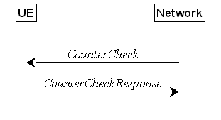
Figure 5.3.6.1-1: Counter check procedure
The counter check procedure is used by the
network to request the UE to verify the amount of data sent/ received on each DRB. More specifically, the UE is requested
to check if, for each DRB, the most significant bits of the COUNT match with
the values indicated by the network.
NOTE: The procedure enables the network to
detect packet insertion by an intruder (a 'man in the middle').
5.3.6.2 Initiation
The network
initiates the procedure by sending a CounterCheck message.
NOTE: The network may initiate the procedure
when any of the COUNT values reaches a specific value.
5.3.6.3 Reception of the CounterCheck message by the UE
Upon receiving the CounterCheck
message, the UE shall:
1> for each DRB that is established:
2> if no COUNT exists for a given direction
(uplink or downlink) because it is a uni-directional bearer configured only for
the other direction:
3> assume the COUNT value to be 0 for the
unused direction;
2> if the drb-Identity is not included
in the drb-CountMSB-InfoList:
3> include the DRB in the drb-CountInfoList in the CounterCheckResponse message by
including the drb-Identity, the count-Uplink and the count-Downlink
set to the value of TX_NEXT – 1 and RX_NEXT – 1 (specified in TS 38.323 [5]),
respectively;
2> else if, for at least one direction, the
most significant bits of the COUNT are different from the value indicated in
the drb-CountMSB-InfoList:
3> include the DRB in the drb-CountInfoList in the CounterCheckResponse message by
including the drb-Identity, the count-Uplink and the count-Downlink
set to the value of TX_NEXT – 1 and RX_NEXT – 1 (specified in TS 38.323 [5]),
respectively;
1> for each DRB that is included in the drb-CountMSB-InfoList in the CounterCheck message that is not established:
2> include the DRB in the drb-CountInfoList in the CounterCheckResponse message by
including the drb-Identity, the count-Uplink and the count-Downlink
with the most significant bits set identical to the corresponding values in the
drb-CountMSB-InfoList
and the least significant bits set to zero;
1> submit the CounterCheckResponse message to lower
layers for transmission upon which the procedure ends.
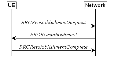
Figure 5.3.7.1-1: RRC connection re-establishment,
successful
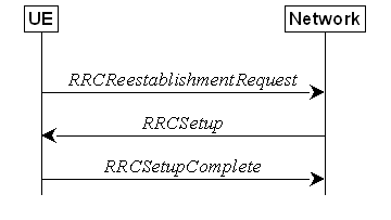
Figure 5.3.7.1-2: RRC re-establishment, fallback
to RRC establishment, successful
The purpose of this procedure is to
re-establish the RRC connection. A UE in RRC_CONNECTED, for which AS security
has been activated with SRB2 and at least one DRB/multicast MRB setup or, for
IAB and NCR, SRB2, may initiate the procedure in order to continue the RRC
connection. The connection re-establishment succeeds if the network is able to
find and verify a valid UE context or, if the UE context cannot be retrieved,
and the network responds with an RRCSetup according to clause 5.3.3.4.
The network applies the procedure e.g as
follows:
- When AS security has been activated and the
network retrieves or verifies the UE context:
- to re-activate AS security without changing
algorithms;
- to re-establish and resume the SRB1;
- When UE is re-establishing an RRC connection,
and the network is not able to retrieve or verify the UE context:
- to discard the stored AS Context and release
all RBs and BH RLC channels and Uu Relay RLC channels;
- to fallback to establish a new RRC
connection.
If AS security has not been activated, the
UE shall not initiate the procedure but instead moves to RRC_IDLE directly,
with release cause 'other'. If AS security has been activated, but SRB2 and at
least one DRB or multicast MRB or, for IAB and NCR, SRB2, are not setup, the UE
does not initiate the procedure but instead moves to RRC_IDLE directly, with
release cause 'RRC connection failure'.
The UE initiates the procedure when one of
the following conditions is met:
1> upon detecting radio link failure of the MCG
and t316 is not configured, in accordance with 5.3.10; or
1> upon detecting radio link failure of the MCG
while SCG transmission is suspended, in accordance with 5.3.10; or
1> upon detecting radio link failure of the MCG
while PSCell change or PSCell addition is ongoing, in accordance with 5.3.10;
or
1> upon detecting radio link failure of the MCG
while the SCG is deactivated, in accordance with 5.3.10; or
1> upon re-configuration with sync failure of
the MCG, in accordance with clause 5.3.5.8.3; or
1> upon mobility from NR failure, in accordance
with clause 5.4.3.5; or
1> upon integrity check failure indication from
lower layers concerning SRB1 or SRB2, except if the integrity check failure is
detected on the RRCReestablishment message; or
1> upon an RRC connection reconfiguration
failure, in accordance with clause 5.3.5.8.2; or
1> upon detecting radio link failure for the
SCG while MCG transmission is suspended, in accordance with clause 5.3.10.3 in
NR-DC or in accordance with TS 36.331 [10] clause 5.3.11.3 in NE-DC; or
1> upon reconfiguration with sync failure of
the SCG while MCG transmission is suspended in accordance with clause
5.3.5.8.3; or
1> upon SCG change failure while MCG
transmission is suspended in accordance with TS 36.331 [10] clause 5.3.5.7a; or
1> upon SCG configuration failure while MCG
transmission is suspended in accordance with clause 5.3.5.8.2 in NR-DC or in
accordance with TS 36.331 [10] clause 5.3.5.5 in NE-DC; or
1> upon integrity check failure indication from
SCG lower layers concerning SRB3 while MCG is suspended; or
1> upon T316 expiry, in accordance with clause 5.7.3b.5; or
1> upon detecting
sidelink radio link failure by L2 U2N Remote UE in RRC_CONNECTED which is not configured with MP, in
accordance with clause 5.8.9.3; or
1> upon reception of NotificationMessageSidelink
including indicationType by L2 U2N Remote UE in RRC_CONNECTED which is not configured with MP, in
accordance with clause 5.8.9.10; or
1> upon PC5 unicast link release for the serving L2 U2N Relay UE indicated
by upper layer at L2 U2N Remote UE in RRC_CONNECTED
which is not configured with MP while T301 is not
running; or
1> if MP is configured, upon detecting radio
link failure of the MCG (i.e. direct path) in accordance with clause 5.3.10
while the transmission of indirect path is suspended as specified in 5.3.5.17;
or
1> if MP is configured,
upon detecting radio link failure of the MCG (i.e. direct path) in accordance with 5.3.10 while MP indirect path addition or change
is ongoing; or
1> if MP is configured, upon detecting sidelink
radio link failure of SL indirect path by L2 U2N Remote UE, in accordance with
clause 5.8.9.3, while MCG transmission (i.e. direct path) is suspended as
specified in clause 5.7.3b; or
1> if MP is configured, upon reception of NotificationMessageSidelink
including indicationType in accordance with clause 5.8.9.10, while MCG
transmission (i.e. direct path) is suspended as specified in clause 5.7.3b; or
1> if MP is configured, upon PC5 unicast link
release indicated by upper layer at L2 U2N Remote UE, while MCG transmission
(i.e. direct path) is suspended as specified in clause 5.7.3b; or
1> if MP is configured, upon detecting the
failure of N3C indirect path by N3C remote UE in accordance with clause 5.7.3c,
while MCG transmission (i.e. direct path) is suspended.
NOTE 0: It is up to UE implementation whether to
initiate the procedure while T346g is running.
Upon initiation of the procedure, the UE
shall:
1> stop timer T310, if running;
1> stop timer T312, if running;
1> stop timer T304, if running;
1> start timer T311;
1> stop timer T316, if running;
1> stop timer T421, if running;
1> if UE is not configured with attemptCondReconfig;
and
1> if UE is not configured with attemptLTM-Switch:
2> reset MAC;
2> release spCellConfig, if configured;
2> suspend all RBs, and BH RLC channels for
IAB-MT, and Uu Relay RLC channels for L2 U2N Relay UE, except SRB0 and
broadcast MRBs;
2> release the MCG SCell(s), if configured;
2> if MR-DC is configured:
3> perform MR-DC release, as specified in
clause 5.3.5.10;
2> perform the LTM configuration release
procedure for the MCG and the SCG as specified in clause 5.3.5.18.7;
2> release delayBudgetReportingConfig,
if configured and stop timer
T342, if running;
2> release overheatingAssistanceConfig,
if configured and stop timer
T345, if running;
2> release idc-AssistanceConfig, if
configured;
2> release btNameList, if configured;
2> release wlanNameList, if configured;
2> release sensorNameList, if
configured;
2> release drx-PreferenceConfig for the
MCG, if configured and stop
timer T346a associated with the MCG, if running;
2> release maxBW-PreferenceConfig for
the MCG, if configured and stop
timer T346b associated with the
MCG, if running;
2> release maxCC-PreferenceConfig for
the MCG, if configured and stop
timer T346c associated with the
MCG, if running;
2> release maxMIMO-LayerPreferenceConfig
for the MCG, if configured and stop
timer T346d associated with the
MCG, if running;
2> release minSchedulingOffsetPreferenceConfig
for the MCG, if configured stop
timer T346e associated with the
MCG, if running;
2> release rlm-RelaxationReportingConfig for the MCG, if
configured and stop timer T346j
associated with the MCG, if running;
2> release bfd-RelaxationReportingConfig for the MCG, if
configured and stop timer T346k
associated with the MCG, if running;
2> release releasePreferenceConfig, if
configured stop timer T346f, if running;
2> release onDemandSIB-Request
if configured, and stop timer T350, if running;
2> release referenceTimePreferenceReporting,
if configured;
2> release sl-AssistanceConfigNR, if
configured;
2> release obtainCommonLocation, if
configured;
2> release musim-GapAssistanceConfig, if configured and stop
timer T346h, if running;
2> release musim-GapPriorityAssistanceConfig,
if configured;
2> release musim-LeaveAssistanceConfig, if configured;
2> release musim-CapabilityRestrictionConfig,
if configured and stop timer T346n,
if running;
2> release ul-GapFR2-PreferenceConfig,
if configured;
2> release scg-DeactivationPreferenceConfig,
if configured, and stop timer T346i, if running;
2> release propDelayDiffReportConfig, if
configured;
2> release rrm-MeasRelaxationReportingConfig,
if configured;
2> release maxBW-PreferenceConfigFR2-2,
if configured;
2> release maxMIMO-LayerPreferenceConfigFR2-2,
if configured;
2> release minSchedulingOffsetPreferenceConfigExt,
if configured;
2> release multiRx-PreferenceReportingConfigFR2,
if configured, and stop timer T346m, if running;
2> release aerial-FlightPathAvailabilityConfig,
if configured;
2> release ul-TrafficInfoReportingConfig, if configured, and
stop all instances of timer T346l, if running;
1> release successHO-Config, if
configured;
1> release successPSCell-Config
configured by the PCell, if configured;
1> if any DAPS bearer is configured:
2> reset the source MAC and release the source
MAC configuration;
2> for each DAPS bearer:
3> release the RLC entity or entities as
specified in TS 38.322 [4], clause 5.1.3, and the associated logical channel
for the source SpCell;
3> reconfigure the PDCP entity to release DAPS
as specified in TS 38.323 [5];
2> for each SRB:
3> release the PDCP entity for the source
SpCell;
3> release the RLC entity as specified in TS
38.322 [4], clause 5.1.3, and the associated logical channel for the source
SpCell;
2> release the physical channel configuration
for the source SpCell;
2> discard the keys used in the source SpCell
(the KgNB key, the KRRCenc key, the KRRCint
key, the KUPint key and the KUPenc key), if any;
1> release sl-L2RelayUE-Config for L2
U2N relay operation, if configured;
1> release sl-L2RemoteUE-Config for L2
U2N relay operation, if configured;
1> release the SRAP entity for L2 U2N relay
operation, if configured;
1> release ncr-FwdConfig, if configured;
1> if the UE is NCR-MT:
2> indicate to NCR-Fwd to cease forwarding;
1> if SL indirect path is configured:
2> release cell
identity and relay UE ID configured in sl-IndirectPathAddChange;
2> indicate upper layers to trigger PC5 unicast
link release of the SL indirect path;
1> if N3C indirect path is configured:
2> release n3c-IndirectPathAddChange;
2> consider the non-3GPP connection is not
used;
1> if the UE is acting as a N3C relay UE:
2> release n3c-IndirectPathConfigRelay;
2> consider the non-3GPP connection is not
used;
1> if the UE is acting as L2 U2N Remote UE and MP via L2 U2N Relay UE is not configured:
2> if the PC5-RRC connection with the U2N Relay
UE is determined to be released:
3> indicate upper layers to trigger PC5 unicast
link release;
3> perform either cell selection in accordance
with the cell selection process as specified in TS 38.304 [20], or relay
selection as specified in clause 5.8.15.3, or both;
2> else (i.e., maintain
the PC5 RRC connection):
3> consider the
connected L2 U2N Relay UE as suitable and perform actions as specified in
clause 5.3.7.3a;
NOTE 1: It is up to Remote UE implementation
whether to release or keep the current PC5 unicast link.
1> else:
2> if the UE is capable of L2 U2N Remote UE:
3> perform either cell selection as specified
in TS 38.304 [20], or relay selection as specified in clause 5.8.15.3, or both;
2> else:
3> perform cell selection in accordance with
the cell selection process as specified in TS 38.304 [20].
NOTE 2: For L2 U2N Remote
UE, if both a suitable cell and a suitable relay are available, the UE can
select either one based on its implementation.
Upon selecting a suitable NR cell, the UE
shall:
1> ensure having valid and up to date essential
system information as specified in clause 5.2.2.2;
1> stop timer T311;
1> if T390 is running:
2> stop timer T390 for all access categories;
2> perform the actions as specified in
5.3.14.4;
1> stop the relay (re)selection procedure, if
ongoing;
1> if the cell selection is triggered by
detecting radio link failure of the MCG or re-configuration with sync failure
of the MCG, except for an LTM cell switch procedure following cell selection
performed while timer T311 was running, as specified in 5.3.7.3, or mobility
from NR failure, and
1> if attemptCondReconfig is configured;
and
1> if the selected cell is not configured with CondEventT1,
or the selected cell is configured with CondEventT1 and leaving
condition has not been fulfilled; and
1> if the selected cell is one of the candidate
cells for which the reconfigurationWithSync is included in the masterCellGroup
in the MCG VarConditionalReconfig and the condExecutionCondPSCell
is not configured for the corresponding condReconfigId in the MCG
VarConditionalReconfig:
2> if the UE supports RLF-Report
for conditional handover, set the choCellId in
the VarRLF-Report to the global cell identity, if available, otherwise
to the physical cell identity and carrier frequency of the selected cell;
2> apply the stored condRRCReconfig associated
to the selected cell and perform actions as specified in 5.3.5.3;
NOTE 1: It is left to network implementation to
how to avoid keystream reuse in case of CHO based recovery after a failed
handover without key change.
1> if the cell selection is triggered by
detecting radio link failure of the MCG or re-configuration with sync failure
of the MCG for an LTM cell switch procedure triggered upon the indication by
lower layers as specified in clause 5.3.5.18.6; and
1> if attemptLTM-Switch is configured;
and
1> if the selected cell is one of the LTM
candidate cells in the LTM-Candidate IE within ltm-Config
associated with the MCG:
2> perform the LTM cell switch procedure for
the selected LTM candidate cell according to the actions specified in 5.3.5.18.6;
NOTE 2: In case both attemptCondReconfig
and attemptLTM-Switch are configured, it is left to the UE
implementation which procedure to execute.
1> else:
2> if UE is configured with attemptCondReconfig;
or
2> if UE is configured with attemptLTM-Switch:
3> reset MAC;
3> release spCellConfig, if configured;
3> release the MCG SCell(s), if configured;
3> release delayBudgetReportingConfig,
if configured and stop timer
T342, if running;
3> release overheatingAssistanceConfig ,
if configured and stop timer
T345, if running;
3> if MR-DC is configured:
4> perform MR-DC release, as specified in
clause 5.3.5.10;
3> release idc-AssistanceConfig, if
configured;
3> release btNameList,
if configured;
3> release wlanNameList,
if configured;
3> release sensorNameList,
if configured;
3> release drx-PreferenceConfig for the MCG, if configured and stop timer T346a associated with the
MCG, if running;
3> release maxBW-PreferenceConfig for the MCG, if configured and stop timer T346b associated with the MCG, if running;
3> release maxCC-PreferenceConfig for the MCG, if configured and stop timer T346c associated with the MCG, if running;
3> release maxMIMO-LayerPreferenceConfig for the MCG, if configured and stop timer T346d associated with the MCG, if running;
3> release minSchedulingOffsetPreferenceConfig for the MCG, if configured and stop timer T346e associated with the MCG, if running;
3> release rlm-RelaxationReportingConfig for the MCG, if
configured and stop timer T346j associated with the MCG, if running;
3> release bfd-RelaxationReportingConfig for the MCG, if
configured and stop timer T346k associated with the MCG, if running;
3> release releasePreferenceConfig, if
configured and stop timer T346f, if running;
3> release onDemandSIB-Request
if configured, and stop timer T350, if running;
3> release referenceTimePreferenceReporting, if
configured;
3> release sl-AssistanceConfigNR, if
configured;
3> release obtainCommonLocation,
if configured;
3> release scg-DeactivationPreferenceConfig,
if configured, and stop timer T346i, if running;
3> release musim-GapAssistanceConfig, if configured and stop
timer T346h, if running;
3> release musim-GapPriorityAssistanceConfig,
if configured;
3> release musim-LeaveAssistanceConfig, if configured;
3> release musim-CapabilityRestrictionConfig,
if configured and stop timer T346n,
if running;
3> release propDelayDiffReportConfig, if
configured;
3> release ul-GapFR2-PreferenceConfig,
if configured;
3> release rrm-MeasRelaxationReportingConfig,
if configured;
3> release maxBW-PreferenceConfigFR2-2,
if configured;
3> release maxMIMO-LayerPreferenceConfigFR2-2,
if configured;
3> release minSchedulingOffsetPreferenceConfigExt,
if configured;
3> release aerial-FlightPathAvailabilityConfig,
if configured;
3> release ul-TrafficInfoReportingConfig, if configured, and
stop all instances of timer T346l, if running;
3> suspend all RBs, and BH RLC channels for the
IAB-MT, except SRB0 and broadcast MRBs;
2> remove all the entries within the MCG VarConditionalReconfig,
if any;
2> perform the LTM configuration release
procedure for the MCG and the SCG as specified in clause 5.3.5.18.7;
2> for each measId, if the associated reportConfig
has a reportType set to condTriggerConfig:
3> for the associated reportConfigId:
4> remove the entry with the matching reportConfigId
from the reportConfigList within the VarMeasConfig;
3> if the associated measObjectId is
only associated to a reportConfig with reportType set to condTriggerConfig:
4> remove the entry with the matching measObjectId
from the measObjectList within the VarMeasConfig;
3> remove the entry with the matching measId
from the measIdList within the VarMeasConfig;
2> remove the servingSecurityCellSetIdwithin the VarServingSecurityCellSetID, if any;
2> release the PC5 RLC entity for SL-RLC0, if
any;
2> start timer T301;
2> apply the default L1 parameter values as
specified in corresponding physical layer specifications except for the
parameters for which values are provided in SIB1;
2> apply the default MAC Cell Group
configuration as specified in 9.2.2;
2> apply the CCCH configuration as specified in
9.1.1.2;
2> apply the timeAlignmentTimerCommon
included in SIB1;
2> initiate transmission of the RRCReestablishmentRequest
message in accordance with 5.3.7.4;
NOTE 2a: This procedure applies also if the UE
returns to the source PCell.
NOTE 3: A L2 U2N Relay UE may re-establish (e.g.
via release and establish) the SL-RLC0 and SL-RLC1 of the connected L2 U2N Remote
UE(s).
Upon selecting an inter-RAT cell, the UE
shall:
1> perform the actions upon going to RRC_IDLE
as specified in 5.3.11, with release cause 'RRC connection failure'.
Upon selecting a suitable L2 U2N Relay UE, the L2 U2N Remote UE
shall:
1> indicate to upper
layer to trigger the PC5 unicast link establishment with the selected L2 U2N Relay UE, if a new L2 U2N
Relay UE is selected;
1> ensure having valid and up to date essential
system information as specified in clause 5.2.2.2;
1> stop timer T311;
1> if T390 is running:
2> stop timer T390 for all access categories;
2> perform the actions as specified in
5.3.14.4;
1> stop the cell selection procedure, if
ongoing;
1> start timer T301;
1> release the RLC entity for SRB0, if any;
1> establish a SRAP
entity as specified in TS 38.351 [66], if no SRAP entity has been established;
1> apply the specified configuration of SL-RLC0
as specified in 9.1.1.4;
1> apply the SDAP configuration and PDCP
configuration as specified in 9.1.1.2 for SRB0;
1> initiate
transmission of the RRCReestablishmentRequest message in accordance with
5.3.7.4.
The UE shall set the contents of RRCReestablishmentRequest
message as follows:
1> if the procedure was initiated due to radio
link failure as specified in 5.3.10.3 or reconfiguration
with sync failure as specified in 5.3.5.8.3; or
1> if the procedure was initiated due to
mobility from NR failure as specified in 5.4.3.5 and if voiceFallbackIndication
is included in the MobilityFromNRCommand message:
2> set the reestablishmentCellId in the VarRLF-Report
to the global cell identity of the selected cell;
1> set the ue-Identity as follows:
2> set the c-RNTI to the C-RNTI used in
the source PCell (reconfiguration with sync or mobility from NR failure) or
used in the PCell in which the trigger for the re-establishment occurred (other
cases);
2> set the physCellId to the physical
cell identity of the source PCell (reconfiguration with sync or mobility from
NR failure) or of the PCell in which the trigger for the re-establishment
occurred (other cases);
2> set the shortMAC-I to the 16 least
significant bits of the MAC-I calculated:
3> over the ASN.1 encoded as per clause 8
(i.e., a multiple of 8 bits) VarShortMAC-Input;
3> with the KRRCint key and
integrity protection algorithm that was used in the source PCell
(reconfiguration with sync or mobility from NR failure) or of the PCell in
which the trigger for the re-establishment occurred (other cases); and
3> with all input bits for COUNT, BEARER and
DIRECTION set to binary ones;
1> set the reestablishmentCause as
follows:
2> if the re-establishment procedure was
initiated due to reconfiguration failure as specified in 5.3.5.8.2:
3> set the reestablishmentCause to the
value reconfigurationFailure;
2> else if the re-establishment procedure was
initiated due to reconfiguration with sync failure as specified in 5.3.5.8.3
(intra-NR handover failure) or 5.4.3.5 (inter-RAT mobility from NR failure):
3> set the reestablishmentCause to the
value handoverFailure;
2> else:
3> set the reestablishmentCause to the
value otherFailure;
1> re-establish PDCP for SRB1;
1> if the UE is acting as L2 U2N Remote UE:
2> establish or
re-establish (e.g. via release and add) SL RLC entity for SRB1;
2> apply the default configuration of SL-RLC1
as defined in 9.2.4 for SRB1;
2> apply the default configuration of PDCP as defined
in 9.2.1 for SRB1;
2> apply the default configuration of SRAP as
defined in 9.2.5 for SRB1;
1> else:
2> re-establish RLC for SRB1;
2> apply the default configuration defined in
9.2.1 for SRB1;
1> configure lower layers to suspend integrity protection
and ciphering for SRB1;
NOTE: Ciphering is not applied for the
subsequent RRCReestablishment message used to resume the connection. An
integrity check is performed by lower layers, but merely upon request from RRC.
1> resume SRB1;
1> if ta-Report or
ta-ReportATG is configured with value enabled and the UE supports TA
reporting:
2> indicate TA report initiation to lower
layers;
1> submit the RRCReestablishmentRequest
message to lower layers for transmission.
The UE shall:
1> stop timer T301;
1> consider the current cell to be the PCell;
1> update the KgNB key based on the
current KgNB key or the NH, using the received
nextHopChainingCount value, as specified in TS 33.501 [11];
1> store the nextHopChainingCount value
indicated in the RRCReestablishment message;
1> derive the KRRCenc and KUPenc
keys associated with the previously configured cipheringAlgorithm, as
specified in TS 33.501 [11];
1> derive the KRRCint and KUPint
keys associated with the previously configured integrityProtAlgorithm,
as specified in TS 33.501 [11].
1> request lower layers to verify the integrity
protection of the RRCReestablishment message, using the previously
configured algorithm and the KRRCint key;
1> if the integrity protection check of the RRCReestablishment
message fails:
2> perform the actions upon going to RRC_IDLE
as specified in 5.3.11, with release cause 'RRC connection failure', upon which
the procedure ends;
1> configure lower layers to resume integrity
protection for SRB1 using the previously configured algorithm and the KRRCint
key immediately, i.e., integrity protection shall be applied to all subsequent
messages received and sent by the UE, including the message used to indicate
the successful completion of the procedure;
1> configure lower layers to resume ciphering
for SRB1 using the previously configured algorithm and, the KRRCenc
key immediately, i.e., ciphering shall be applied to all subsequent messages
received and sent by the UE, including the message used to indicate the
successful completion of the procedure;
1> release the measurement gap configuration
indicated by the measGapConfig, if configured;
1> release the MUSIM gap configuration
indicated by the musim-GapConfig, if configured;
1> release the FR2 UL gap configuration
indicated by the ul-GapFR2-Config, if configured;
1> perform the L2 U2N Remote UE configuration
procedure in accordance with the received sl-L2RemoteUE-Config as
specified in 5.3.5.16;
1> for each application layer measurement
configuration with appLayerIdleInactiveConfig configured:
2> if the RPLMN is not included in plmn-IdentityList
in VarAppLayerPLMN-ListConfig:
3> forward the measConfigAppLayerId and
inform upper layers about the release of the application layer measurement
configuration;
3> release the application layer measurement
configuration including its fields in the UE variables VarAppLayerIdleConfig
and VarAppLayerPLMN-ListConfig;
3> discard any application layer measurement
reports which were not yet fully submitted to lower layers for transmission;
3> consider itself not to be configured to send
application layer measurement reports for the measConfigAppLayerId;
1> set the content of RRCReestablishmentComplete
message as follows:
2> if the UE has logged measurements available
for NR and if the RPLMN is included in plmn-IdentityList stored in VarLogMeasReport;
or
2> if the UE has logged measurements available
for NR and if the current registered SNPN identity is included in snpn-ConfigID-List
stored in VarLogMeasReport:
3> include the logMeasAvailable in the RRCReestablishmentComplete message;
3> if Bluetooth measurement results are
included in the logged measurements the UE has available for NR:
4> include the logMeasAvailableBT in the RRCReestablishmentComplete message;
3> if WLAN measurement results are included in
the logged measurements the UE has available for NR:
4> include the logMeasAvailableWLAN in the RRCReestablishmentComplete message;
2> if the sigLoggedMeasType
in VarLogMeasReport is included; or
2> if the UE supports the override protection of
the signalling based logged MDT for inter-RAT (i.e. LTE
to NR), and if the sigLoggedMeasType in VarLogMeasReport
of TS 36.331 [10] is included:
3> if T330 timer is running (associated to the
logged measurement configuration for NR or for LTE):
4> set sigLogMeasConfigAvailable to true
in the RRCReestablishmentComplete message;
3> else:
4> if the UE has logged measurements in VarLogMeasReport
or in VarLogMeasReport of TS 36.331 [10]:
5> set sigLogMeasConfigAvailable to false
in the RRCReestablishmentComplete message;
2> if the UE has connection establishment
failure or connection resume failure information available in VarConnEstFailReport
or VarConnEstFailReportList and if the RPLMN is equal to plmn-Identity stored in VarConnEstFailReport
or in at least one of the entries of VarConnEstFailReportList; or
2> if the UE supports multiple CEF report and
if the UE has connection establishment failure information or connection resume
failure information available in VarConnEstFailReport or VarConnEstFailReportList
and if the registered SNPN identity is equal to snpn-Identity in networkIdentity
stored in VarConnEstFailReport or any entry
of VarConnEstFailReportList:
3> include connEstFailInfoAvailable in the RRCReestablishmentComplete message;
2> if the UE has radio link failure or handover
failure information available in VarRLF-Report and if the RPLMN is
included in plmn-IdentityList stored in VarRLF-Report; or
2> if the UE has radio link failure or handover
failure information available in VarRLF-Report of TS 36.331 [10] and if
the UE is capable of cross-RAT RLF reporting and if the RPLMN is included in
plmn-IdentityList stored in VarRLF-Report of TS 36.331 [10]; or
2> if the UE has radio link failure or handover
failure information available in VarRLF-Report and if the current registered SNPN identity is included in snpn-IdentityList
stored in VarRLF-Report:
3> include rlf-InfoAvailable in the RRCReestablishmentComplete
message;
2> if the UE has successful handover
information available in VarSuccessHO-Report and if the RPLMN is
included in plmn-IdentityList stored in VarSuccessHO-Report; or
2> if the UE has successful handover
information available in VarSuccessHO-Report and if the current registered SNPN identity is included in snpn-IdentityList
stored in the VarSuccessHO-Report:
3> include successHO-InfoAvailable in the RRCReestablishmentComplete
message;
2> if the UE has successful PSCell change or
addition information available in VarSuccessPSCell-Report and if the
RPLMN is included in plmn-IdentityList stored in VarSuccessPSCell-Report;
or
2> if the UE has successful PSCell change or
addition information available in VarSuccessPSCell-Report and if the current registered SNPN identity is included in snpn-IdentityList
stored in the VarSuccessPSCell-Report:
3> include successPSCell-InfoAvailable in the RRCReestablishmentComplete message;
2> if the UE has flight path information
available:
3> include flightPathInfoAvailable;
2> if the UE has at least one stored
application layer measurement configuration with appLayerIdleInactiveConfig
configured which has not been successfully transmitted since entering
RRC_CONNECTED state:
3> include measConfigReportAppLayerAvailable
in the RRCReestablishmentComplete message;
2> if SIB1 contains musim-CapRestrictionAllowed:
3> if supported, include the musim-CapRestrictionInd in the RRCReestablishmentComplete message upon determining it has temporary capability restriction;
NOTE: Upon reception of musim-CapRestrictionInd
in RRCReestablishmentComplete, it is up to network implementation to
configure the UE with a limited configuration that is used until network sends RRCReconfiguration
based on the actual restricted UE capabilities included in UEAssistanceInformation.
1> submit the RRCReestablishmentComplete
message to lower layers for transmission;
1> if SIB21 is provided by the PCell; or
1> if nonServingCellMII is provided in SIB1 by the
PCell:
2> if the UE initiated transmission of an MBSInterestIndication
message during the last 1 second preceding detection of radio link failure:
3> initiate transmission of an MBSInterestIndication
message in accordance with 5.9.4;
1> the procedure ends.
Upon T311 expiry, the UE shall:
1> if the procedure was initiated due to radio
link failure or handover failure:
2> set the noSuitableCellFound in the VarRLF-Report
to true;
1> perform the actions upon going to RRC_IDLE
as specified in 5.3.11, with release cause 'RRC connection failure'.
The UE shall:
1> if timer T301 expires; or
1> if the selected cell becomes no longer
suitable according to the cell selection criteria as specified in TS 38.304
[20]; or
1> if the (re)selected
L2 U2N Relay UE becomes unsuitable; or
1> upon reception of NotificationMessageSidelink
indicating relayUE-HO or relayUE-CellReselection; or
1> upon PC5 unicast link release indicated by
upper layer at L2 U2N Remote UE:
2> perform the actions upon going to RRC_IDLE
as specified in 5.3.11, with release cause 'RRC connection failure'.
The UE shall:
1> perform the RRC connection establishment
procedure as specified in 5.3.3.4.

Figure 5.3.8.1-1: RRC connection release,
successful
The purpose of this procedure is:
- to release the RRC connection, which includes
the release of the established radio bearers (except for broadcast MRBs), BH RLC channels, Uu Relay RLC channels, PC5 Relay RLC channels as well as all radio resources; or
- to suspend the RRC connection only if SRB2
and at least one DRB or multicast MRB or, for IAB and NCR, SRB2, are setup,
which includes the suspension of the established radio bearers (except for
broadcast MRBs).
The network initiates the RRC connection
release procedure to transit a UE in RRC_CONNECTED to RRC_IDLE; or to transit a
UE in RRC_CONNECTED to RRC_INACTIVE only if SRB2 and at least one DRB or
multicast MRB or, for IAB and NCR, SRB2, is setup in RRC_CONNECTED; or to
transit a UE in RRC_INACTIVE back to RRC_INACTIVE when the UE tries to resume
(for resuming a suspended RRC connection, for RNA
Update or for initiating SDT); or to transit a UE in RRC_INACTIVE to
RRC_IDLE when the UE tries to resume (for resuming of a suspended RRC
connection, for RNA Update or for initiating SDT). The procedure can also be
used to release and redirect a UE to another frequency.
The UE shall:
1> delay the following actions defined in this clause
60 ms from the moment the RRCRelease message was received or optionally
when lower layers indicate that the receipt of the RRCRelease message
has been successfully acknowledged, whichever is earlier;
NOTE 0: When the RRCRelease message is
received on a HARQ process with disabled HARQ feedback, and when STATUS
reporting, as defined in TS 38.322 [4], has not been triggered for a logical
channel associated with the SRB1, the lower layers can be considered to have
indicated that the receipt of the RRCRelease message has been
successfully acknowledged.
1> stop timer T380, if running;
1> stop timer T320, if running;
1> if timer T316 is running;
2> stop timer T316;
2> if the UE supports RLF-Report
for fast MCG recovery procedure as specified in 38.306
[26]:
3> set the elapsedTimeT316 in the VarRLF-Report
to the value of the elapsed time of the timer T316;
3> set the pSCellId in the VarRLF-Report
to the global cell identity of the PSCell, if available, otherwise to the
physical cell identity and carrier frequency of the PSCell;
2> else:
3> clear the information included in VarRLF-Report,
if any;
1> stop timer T350, if running;
1> stop timer T346g, if running;
1> stop timer T348, if running;
1> if the AS security is not activated:
2> ignore any field included in RRCRelease message
except waitTime;
2> perform the actions upon going to RRC_IDLE
as specified in 5.3.11 with the release cause 'other' upon which the procedure
ends;
1> if the RRCRelease message includes redirectedCarrierInfo
indicating redirection to eutra:
2> if cnType is included:
3> after the cell selection, indicate the
available CN Type(s) and the received cnType to upper layers;
NOTE 1: Handling the case if the E-UTRA cell
selected after the redirection does not support the core network type specified
by the cnType, is up to UE implementation.
2> if voiceFallbackIndication is
included:
3> consider the RRC connection release was for
EPS fallback for IMS voice (see TS 23.502 [43]);
1> if the RRCRelease message includes
the cellReselectionPriorities:
2> store the cell reselection priority
information provided by the cellReselectionPriorities;
2> if the t320 is included:
3> start timer T320, with the timer value set
according to the value of t320;
1> else:
2> apply the cell reselection priority
information broadcast in the system information;
1> if deprioritisationReq is included and the UE supports RRC connection release with deprioritisation:
2> start or restart timer T325 with the timer
value set to the deprioritisationTimer signalled;
2> store the deprioritisationReq until
T325 expiry/stop;
NOTE 1a: The UE stores the deprioritisation
request irrespective of any cell reselection absolute priority assignments (by
dedicated or common signalling) and regardless of RRC connections in NR or
other RATs unless specified otherwise.
1> if the RRCRelease includes the measIdleConfig:
2> if T331 is running:
3> stop timer T331;
3> perform the actions as specified in 5.7.8.3;
2> if the measIdleConfig is set to setup:
3> store the received measIdleDuration
in VarMeasIdleConfig;
3> start timer T331 with the value set to measIdleDuration;
3> if the measIdleConfig contains measIdleCarrierListNR:
4> store the received measIdleCarrierListNR
in VarMeasIdleConfig;
3> if the measIdleConfig contains measIdleCarrierListEUTRA:
4> store the received measIdleCarrierListEUTRA
in VarMeasIdleConfig;
3> if the measIdleConfig contains validityAreaList:
4> store the received validityAreaList
in VarMeasIdleConfig;
3> if the measIdleConfig contains measReselectionCarrierListNR:
4> store the received measReselectionCarrierListNR
in VarMeasReselectionConfig;
3> if the measIdleConfig contains measReselectionValidityDuration:
4> store the received measReselectionValidityDuration
in VarMeasReselectionConfig;
3> if the measIdleConfig contains measIdleValidityDuration:
4> store the received measIdleValidityDuration
in VarEnhMeasIdleConfig;
1> if the RRCRelease includes suspendConfig:
2> reset MAC and release the default MAC Cell
Group configuration, if any;
2> apply the received suspendConfig except
the received nextHopChainingCount;
2> if the sdt-Config is configured:
3> for each of the DRB in the sdt-DRB-List:
4> consider the DRB to be configured for SDT;
3> if sdt-SRB2-Indication is configured:
4> consider the SRB2 to be configured for SDT;
3> for each RLC bearer (except those associated
with broadcast MRBs and multicast MRBs) that is not suspended:
4> re-establish the RLC entity as specified in
TS 38.322 [4];
3> for SRB2 (if it is resumed) and for SRB1:
4> trigger the PDCP entity to perform SDU
discard as specified in TS 38.323 [5];
3> if sdt-MAC-PHY-CG-Config is configured:
4> configure the PCell with the configured
grant resources for SDT and instruct the MAC entity to start the cg-SDT-TimeAlignmentTimer;
2> if srs-PosRRC-Inactive is configured:
3> apply the SRS for positioning configuration in
RRC_INACTIVE and instruct MAC to start the inactivePosSRS-TimeAlignmentTimer;
2> if srs-PosRRC-InactiveValidityAreaNonPreConfig
is set to setup:
3> apply the SRS for positioning configuration in
RRC_INACTIVE and instruct MAC to start the inactivePosSRS-ValidityAreaTAT;
2> else if srs-PosRRC-InactiveValidityAreaNonPreConfig
is set to release:
3> release srs-PosRRC-InactiveValidityAreaNonPreConfig,
if available;
2> if srs-PosRRC-InactiveValidityAreaPreConfigList
is set to setup:
3> store srs-PosRRC-InactiveValidityAreaPreConfigList
and perform actions as specified in clause 5.7.20;
2> else if srs-PosRRC-InactiveValidityAreaPreConfigList
is set to release:
3> remove all srs-PosRRC-InactiveValidityAreaPreConfigList,
if available;
NOTE 1b: The Network should provide full
configuration to UE for SRS for Positioning in RRC_INACTIVE.
2> perform the LTM configuration release
procedure for the MCG and the SCG as specified in clause 5.3.5.18.7;
2> remove all the entries within the MCG and
the SCG VarConditionalReconfig, if any;
2> remove the servingSecurityCellSetId within
the VarServingSecurityCellSetID, if any;
2> for each measId of the MCG measConfig
and for each measId of the SCG measConfig, if configured, if the
associated reportConfig has a reportType set to condTriggerConfig:
3> for the associated reportConfigId:
4> remove the entry with the matching reportConfigId
from the reportConfigList within the VarMeasConfig;
3> if the associated measObjectId is
only associated to a reportConfig with reportType set to condTriggerConfig:
4> remove the entry with the matching measObjectId
from the measObjectList within the VarMeasConfig;
3> remove the entry with the matching measId
from the measIdList within the VarMeasConfig;
2> if the UE is NCR-MT and if ncr-FwdConfig
is configured:
3> if the ncr-FwdConfig includes
periodic forwarding resource configuration:
4> indicate to NCR-Fwd to continue forwarding
only in accordance with the configured periodic forwarding resource set(s);
3> else:
4> indicate to NCR-Fwd to cease forwarding;
2> if the UE is acting as L2 U2N Remote UE and
is not configured with MP:
3> if the PC5-RRC connection with the U2N Relay
UE is determined to be released:
4> indicate upper layers to trigger PC5 unicast
link release;
3> else (i.e., maintain the PC5 RRC
connection):
4> establish or re-establish (e.g. via release
and add) SL RLC entity for SRB1;
2> else:
3> re-establish RLC entities for SRB1;
2> for each application layer measurement
configuration with appLayerIdleInactiveConfig configured:
3> forward the measConfigAppLayerId and inform
upper layers about the release of the RAN visible application layer measurement
configuration;
3> discard any RAN visible application layer
measurement reports received from upper layers;
3> initiate the procedure in 5.5b.1.2;
2> if the RRCRelease message with suspendConfig
was received in response to an RRCResumeRequest or an RRCResumeRequest1:
3> stop the timer T319 if running;
3> in the stored UE Inactive AS context:
4> replace the KgNB and KRRCint
keys with the current KgNB and KRRCint keys;
4> replace the nextHopChainingCount
with the value of nextHopChainingCount received in the RRCRelease
message;
4> replace the cellIdentity with the cellIdentity
of the cell the UE has received the RRCRelease message;
4> if the suspendConfig contains the sl-UEIdentityRemote
(i.e. the UE is a L2 U2N Remote UE):
5> replace the C-RNTI with the value of the sl-UEIdentityRemote;
5> replace the physical cell identity with
the value of the sl-PhysCellId in sl-ServingCellInfo contained in
the discovery message received from the connected L2 U2N Relay UE;
4> else:
5> replace the C-RNTI with the C-RNTI used in
the cell (see TS 38.321 [3]) the UE has received the RRCRelease message;
5> replace the physical cell identity with
the physical cell identity of the cell the UE has received the RRCRelease
message;
3> replace the nextHopChainingCount
with the value associated with the current KgNB;
3> stop the timer T319a if running and consider
SDT procedure is not ongoing;
2> else:
3> store in the UE Inactive AS Context the nextHopChainingCount received in the RRCRelease
message, the current KgNB and KRRCint keys,
the ROHC state, the EHC context(s), the UDC state, the stored QoS flow to DRB
mapping rules, the application layer measurement configuration, the C-RNTI used
in the source PCell, the cellIdentity and the physical cell identity of
the source PCell, the ncr-FwdConfig (if configured), the spCellConfigCommon
within ReconfigurationWithSync of the NR PSCell (if configured) and
all other parameters configured except for:
- parameters within ReconfigurationWithSync
of the PCell;
- parameters within ReconfigurationWithSync
of the NR PSCell, if configured;
- parameters within MobilityControlInfoSCG
of the E-UTRA PSCell, if configured;
- servingCellConfigCommonSIB;
- sl-L2RelayUE-Config, if configured;
- sl-L2RemoteUE-Config, if configured;
- aerial-Config, if configured;
- cellDTX-DRX-Config, if configured;
NOTE 1c: suspendConfig is not stored as
part of UE Inactive AS Context, except for the fields explicitly specified.
3> store any previously or subsequently
received application layer measurement report containers for which the
successful transmission of the message or at least one segment of the message
has not been confirmed by lower layers;
NOTE 2: NR sidelink communication/discovery/positioning
related configurations and logged measurement configuration are not stored as
UE Inactive AS Context, when UE enters RRC_INACTIVE.
2> suspend all SRB(s) and DRB(s), except SRB0
and broadcast MRBs;
2> suspend all multicast MRB(s) associated with
multicast session(s) not configured for reception in RRC_INACTIVE;
2> indicate PDCP suspend to lower layers of all
DRBs and multicast MRBs associated with multicast session(s) not configured for
reception in RRC_INACTIVE;
2> release Uu Relay RLC channel(s), if
configured;
2> release PC5 Relay RLC channel(s), if
configured;
2> release the SRAP entity, if configured;
NOTE 2a: A L2 U2N Relay UE may re-establish the
SL-RLC0, SL-RLC1 and SRAP entity after release.
2> if SL indirect path
is configured:
3> release cell
identity and relay UE ID configured in
sl-IndirectPathAddChange;
3> indicate upper layers to trigger PC5 unicast
link release of the SL indirect path;
2> if N3C indirect path is configured:
3> release n3c-IndirectPathAddChange;
3> consider the non-3GPP connection is not
used;
2> if the UE is acting as a N3C relay UE:
3> release n3c-IndirectPathConfigRelay;
3> consider the non-3GPP connection is not
used;
2> if the t380 is included:
3> start timer T380, with the timer value set
to t380;
2> if the RRCRelease message is
including the waitTime:
3> start timer T302 with the value set to the waitTime;
3> inform upper layers that access barring is
applicable for all access categories except categories '0' and '2';
2> if T390 is running:
3> stop timer T390 for all access categories;
3> perform the actions as specified in
5.3.14.4;
2> indicate the suspension of the RRC
connection to upper layers;
2> if the UE is capable of L2 U2N Remote UE:
3> enter RRC_INACTIVE, and perform either cell
selection as specified in TS 38.304 [20], or relay selection as specified in
clause 5.8.15.3, or both;
2> else:
3> enter RRC_INACTIVE and perform cell
selection as specified in TS 38.304 [20];
2> if the suspendConfig includes resumeIndication:
3> perform the actions as if the UE received Paging
message with the ue-Identity included in the PagingRecord
matching the UE's stored fullI-RNTI, as specified in clause 5.3.2.3;
2> if the multicastConfigInactive is set
to setup:
3> if the multicast PTM configuration is
provided for at least one multicast session for which the UE is not indicated
to stop monitoring the G-RNTI and the UE selects the same cell as the one on
which the multicast session was configured in RRC_CONNECTED:
4> apply the multicast PTM configuration as
specified in 5.10.3;
4> if multicast MCCH is present:
5> monitor the Multicast MCCH-RNTI as specified
in 5.10.1.2;
1> else:
2> perform the actions upon going to RRC_IDLE
as specified in 5.3.11, with the release cause 'other'.
NOTE 3: Whether to release the PC5 unicast link
is left to L2 U2N Remote UE's implementation.
NOTE 4: It is left to UE
implementation whether to stop T430, if running, when going to RRC_INACTIVE.
The UE shall:
1> if T320 expires:
2> if stored, discard the cell reselection
priority information provided by the cellReselectionPriorities or
inherited from another RAT;
2> apply the cell reselection priority
information broadcast in the system information.
Upon receiving the expiry of DataInactivityTimer
from lower layers while in RRC_CONNECTED, the UE shall:
1> perform the actions upon going to RRC_IDLE
as specified in 5.3.11, with release cause 'RRC connection failure'.
The UE shall:
1> if T346g expires:
2> perform the actions upon going to RRC_IDLE
as specified in 5.3.11, with release cause 'other'.
The purpose of this procedure is to release
the RRC connection. Access to the current PCell may be barred as a result of
this procedure.
The UE initiates the procedure when upper
layers request the release of the RRC connection as specified in TS 24.501
[23]. The UE shall not initiate the procedure for power saving purposes.
The UE shall:
1> if the upper layers indicate barring of the
PCell:
2> treat the PCell used prior to entering
RRC_IDLE as barred according to TS 38.304 [20];
1> perform the actions upon going to RRC_IDLE
as specified in 5.3.11, with release cause 'other'.
The UE shall:
1> if any DAPS bearer is configured, upon
receiving N310 consecutive "out-of-sync" indications for the source
SpCell from lower layers and T304 is running:
2> start timer T310 for the source SpCell.
1> upon receiving N310 consecutive
"out-of-sync" indications for the SpCell from lower layers while
neither T300, T301, T304, T311, T316 nor T319 are running:
2> start timer T310 for the corresponding
SpCell.
Upon receiving N311 consecutive
"in-sync" indications for the SpCell from lower layers while T310 is
running, the UE shall:
1> stop timer T310 for the corresponding
SpCell.
1> stop timer T312 for the corresponding
SpCell, if running.
NOTE 1: In this case, the UE maintains the RRC
connection without explicit signalling, i.e. the UE maintains the entire radio
resource configuration.
NOTE 2: Periods in time where neither
"in-sync" nor "out-of-sync" is reported by L1 do not affect
the evaluation of the number of consecutive "in-sync" or
"out-of-sync" indications.
The UE shall:
1> if any DAPS bearer is configured and T304 is
running:
2> upon T310 expiry in source SpCell; or
2> upon random access problem indication from
source MCG MAC; or
2> upon indication from source MCG RLC that the
maximum number of retransmissions has been reached; or
2> upon consistent uplink LBT failure
indication from source MCG MAC:
3> consider radio link failure to be detected
for the source MCG i.e. source RLF;
3> suspend the transmission
and reception of all DRBs and multicast MRBs in the source MCG;
3> reset MAC for the source
MCG;
3> release the source
connection.
1> else:
2> during a DAPS handover: the following only
applies for the target PCell;
2> upon T310 expiry in PCell; or
2> upon T312 expiry in PCell; or
2> upon random access problem indication from
MCG MAC while neither T300, T301, T304, T311 nor T319 are running and SDT
procedure is not ongoing; or
2> upon indication from MCG RLC that the
maximum number of retransmissions has been reached while SDT procedure is not
ongoing; or
2> if connected as an IAB-node, upon BH RLF
indication received on BAP entity from the MCG; or
2> upon consistent uplink LBT failure
indication from MCG MAC while T304 is not running:
3> if the indication is from MCG RLC and CA
duplication is configured and activated for MCG, and for the corresponding
logical channel allowedServingCells only includes SCell(s):
4> initiate the failure information procedure
as specified in 5.7.5 to report RLC failure.
3> else:
4> consider radio link failure to be detected
for the MCG, i.e. MCG RLF;
4> discard any segments of segmented RRC
messages stored according to 5.7.6.3;
NOTE 1: Void.
4> if AS security has not been activated:
5> perform the actions upon going to RRC_IDLE
as specified in 5.3.11, with release cause 'other';-
4> else if AS security has been activated but
SRB2 and at least one DRB or multicast MRB or, for IAB and NCR, SRB2, have not
been setup:
5> store the radio link failure information in
the VarRLF-Report as described in clause 5.3.10.5;
5> perform the actions upon going to RRC_IDLE
as specified in 5.3.11, with release cause 'RRC connection failure';
4> else:
5> store the radio link failure information in
the VarRLF-Report as described in clause 5.3.10.5;
5> if MP is configured:
6> if T316 is configured, and MP indirect path
transmission is not suspended; and
6> if neither MP indirect path change nor MP
indirect path addition is ongoing:
7> initiate the MCG failure information
procedure as specified in 5.7.3b to report MCG radio link failure.
6> else:
7> initiate the connection re-establishment
procedure as specified in 5.3.7.
5> else:
6> if the UE supports
RLF-Report for fast MCG recovery procedure and if T316
is configured:
7> if the SCG is deactivated at the moment of
detecting RLF in the MCG:
8> set the mcg-RecoveryFailureCause in
the VarRLF-Report to scg-Deactivated;
8> set the pSCellId in the VarRLF-Report
to the global cell identity of the PSCell, if available, otherwise to the
physical cell identity and carrier frequency of the PSCell;
7> else if SCG transmission is suspended at the
moment of detecting RLF in the MCG:
8> set the pSCellId in the VarRLF-Report
to the global cell identity of the PSCell, if available, otherwise to the
physical cell identity and carrier frequency of the PSCell;
8> set the scg-FailureCause value in the
VarRLF-Report according to 5.7.3.5;
8> set the elapsedTimeSCG-Failure in the
VarRLF-Report to the time elapsed between SCG failure and the MCG
failure;
6> if T316 is configured; and
6> if SCG transmission is not suspended; and
6> if the SCG is not deactivated; and
6> if neither PSCell change nor PSCell addition
is ongoing (i.e. timer T304 for the NR PSCell is not running in case of NR-DC
or timer T307 of the E-UTRA PSCell is not running as specified in TS 36.331
[10], clause 5.3.10.10, in NE-DC):
7> initiate the MCG failure information
procedure as specified in 5.7.3b to report MCG radio link failure.
6> else:
7> initiate the connection re-establishment
procedure as specified in 5.3.7.
A L2/L3 U2N Relay UE shall:
1> upon detecting radio link failure:
2> either indicate to upper layers (to trigger
PC5 unicast link release) or send NotificationMessageSidelink to the
connected L2/L3 U2N Remote UE(s) in accordance with 5.8.9.10.
A N3C Relay UE shall:
1> upon detecting radio link failure:
2> indicates to the associated N3C remote UE
via the Non-3GPP Connection.
NOTE 2: How the N3C Relay UE indicates Uu RLF on
the Non-3GPP Connection is left to implementation.
The UE shall:
1> upon T310 expiry in PSCell; or
1> upon T312 expiry in PSCell; or
1> upon random access problem indication from
SCG MAC; or
1> upon indication from SCG RLC that the
maximum number of retransmissions has been reached; or
1> if connected as an IAB-node, upon BH RLF
indication received on BAP entity from the SCG; or
1> upon consistent uplink LBT failure
indication from SCG MAC:
2> if the indication is from SCG RLC and CA
duplication is configured and activated for SCG, and for the corresponding
logical channel allowedServingCells only includes SCell(s):
3> initiate the failure information procedure
as specified in 5.7.5 to report RLC failure.
2> else:
3> consider radio link failure to be detected
for the SCG, i.e. SCG RLF;
3> if the SCG is deactivated:
4> stop radio link monitoring on the SCG;
4> indicate to lower layers to stop beam
failure detection on the PSCell;
3> if MCG transmission is not suspended:
4> initiate the SCG failure information
procedure as specified in 5.7.3 to report SCG radio link failure.
3> else:
4> if the UE is in NR-DC:
5> if the UE supports RLF-Report for fast MCG
recovery procedure and if the UE detected SCG failure while the timer T316 was
running:
6> set the pSCellId in the VarRLF-Report
to the global cell identity of the PSCell, if available, otherwise to the
physical cell identity and carrier frequency of the PSCell;
6> set the scg-FailureCause in the VarRLF-Report
value according to 5.7.3.5;
6> set the elapsedTimeSCG-Failure in the
VarRLF-Report to the time elapsed between MCG failure and the SCG
failure;
6> include scg-FailedAfterMCG;
5> initiate the connection re-establishment
procedure as specified in 5.3.7;
4> else (the UE is in (NG)EN-DC):
5> initiate the connection re-establishment
procedure as specified in TS 36.331 [10], clause 5.3.7;
The UE shall set the rlf-Cause in the VarRLF-Report
as follows:
1> if the UE declares radio link failure due to
T310 expiry:
2> set the rlf-Cause as t310-Expiry;
1> else if the UE declares radio link failure
due to the random access problem indication from MCG MAC:
2> if the random access procedure was initiated
for beam failure recovery:
3> set the rlf-Cause as beamFailureRecoveryFailure;
2> else:
3> set the rlf-Cause as randomAccessProblem;
1> else if the UE declares radio link failure
due to the reaching of maximum number of retransmissions from the MCG RLC:
2> set the rlf-Cause as rlc-MaxNumRetx;
1> else if the UE declares radio link failure
due to consistent uplink LBT failures:
2> set the rlf-Cause as lbtFailure;
1> else if the IAB-MT declares radio link
failure due to the reception of a BH RLF indication on
BAP entity:
2> set the rlf-Cause as bh-rlfRecoveryFailure.
1> else if the UE declares radio link failure
due to T312 expiry:
2> set the rlf-Cause as t312-Expiry;
5.3.10.5 RLF report content determination
The UE shall determine
the content in the VarRLF-Report as follows:
1> clear the information included in VarRLF-Report,
if any;
1> if the UE is not in SNPN access mode, set
the plmn-IdentityList to include the list of EPLMNs stored by the UE
(i.e. including the RPLMN);
1> else if the UE is in SNPN access mode, set
the snpn-IdentityList to include the list of equivalent SNPNs stored by
the UE (i.e., including the registered SNPN identity);
1> set the measResultLastServCell
to include the cell level RSRP, RSRQ and the available SINR, of the source PCell (in case HO failure) or PCell (in case RLF) based on the available SSB and CSI-RS measurements collected up to
the moment the UE detected failure;
1> if measRSSI-ReportConfig is
configured for the measObject indicated as the servingCellMO of
the source PCell (in case HO failure) or PCell (in case of RLF), set the measResultLastServCellRSSI to
the linear average of the available RSSI sample value(s) provided by lower
layers for the frequency of the source PCell (in case
HO failure) or PCell (in case of RLF) up to the moment
the UE detected the failure;
1> if the SS/PBCH
block-based measurement quantities are available:
2> set the rsIndexResults
in measResultLastServCell to include all the available measurement
quantities of the source PCell (in case HO failure) or PCell (in case RLF),
ordered such that the highest SS/PBCH block RSRP is listed first if SS/PBCH
block RSRP measurement results are available, otherwise the highest SS/PBCH
block RSRQ is listed first if SS/PBCH block RSRQ measurement results are
available, otherwise the highest SS/PBCH block SINR is listed first, based on
the available SS/PBCH block based measurements collected up to the moment the
UE detected failure;
1> if the CSI-RS based
measurement quantities are available:
2> set the rsIndexResults
in measResultLastServCell to include all the available measurement
quantities of the source PCell (in case HO failure) or PCell (in case RLF),
ordered such that the highest CSI-RS RSRP is listed first if CSI-RS RSRP
measurement results are available, otherwise the highest CSI-RS RSRQ is listed
first if CSI-RS RSRQ measurement results are available, otherwise the highest
CSI-RS SINR is listed first, based on the available CSI-RS based measurements
collected up to the moment the UE detected failure;
1> for each of the
configured measObjectNR in which measurements are available:
2> if the SS/PBCH
block-based measurement quantities are available:
3> set the measResultListNR
in measResultNeighCells to include all the available measurement
quantities of the best measured cells, other than the source PCell (in case HO
failure) or PCell (in case RLF), ordered such that the cell with highest
SS/PBCH block RSRP is listed first if SS/PBCH block RSRP measurement results
are available, otherwise the cell with highest SS/PBCH block RSRQ is listed
first if SS/PBCH block RSRQ measurement results are available, otherwise the
cell with highest SS/PBCH block SINR is listed first, based on the available
SS/PBCH block based measurements collected up to the moment the UE detected
failure;
3> for each neighbour
cell included, include the optional fields that are available;
NOTE 0a: For the
neighboring cells included in measResultListNR in measResultNeighCells
ordered based on the SS/PBCH block measurement
quantities, UE also includes the
CSI-RS based measurement quantities, if available.
2> if the CSI-RS based
measurement quantities are available:
3> set the measResultListNR in measResultNeighCells
to include all the available measurement quantities of the best measured cells,
other than the source PCell (in case HO failure) or PCell (in case RLF),
ordered such that the cell with highest CSI-RS RSRP is listed first if CSI-RS
RSRP measurement results are available, otherwise the cell with highest CSI-RS
RSRQ is listed first if CSI-RS RSRQ measurement results are available,
otherwise the cell with highest CSI-RS SINR is listed first, based on the
available CSI-RS based measurements collected up to the moment the UE detected
radio link failure;
3> for each neighbour
cell included, include the optional fields that are available;
NOTE 0b: For ordering the
neighboring cells based on the CSI-RS measurement
quantities, UE includes measurements only for the cells not yet included in measResultListNR in measResultNeighCells to avoid overriding SS/PBCH block-based ordered measurements.
2> for each neighbour cell, if any, included in
measResultListNR in measResultNeighCells:
3> if the UE supports RLF-Report for conditional handover and if
the neighbour cell is one of the candidate cells for which the
reconfigurationWithSync is included in the masterCellGroup in the
MCG VarConditionalReconfig at the moment of the detected failure:
4> set choConfig in MeasResult2NR to the execution condition for each measId within condTriggerConfig associated to the
neighbour cell within the MCG VarConditionalReconfig;
4> if the first entry of choConfig corresponds to a fulfilled
execution condition at the moment of handover failure, or radio link failure; or
4> if the second entry of choConfig, if available, corresponds to
a fulfilled execution condition at the moment of handover failure, or radio link failure:
5> set firstTriggeredEvent to the
execution condition condFirstEvent corresponding to the first entry of choConfig or to the execution condition condSecondEvent
corresponding to the second entry of choConfig, whichever execution condition was fulfilled first in time;
5> set timeBetweenEvents
to the elapsed time between the point in time of
fulfilling the condition in choConfig that was fulfilled first in time, and the point in time of
fulfilling the condition in choConfig that was fulfilled second in time, if both the first execution
condition corresponding to the first entry and the second execution condition
corresponding to the second entry in the choConfig were fulfilled;
1> for each of the
configured measObjectNR associated with neighboring cells if the
associated reportConfigNR includes measRSSI-ReportConfig:
2> set the measResultNeighFreqRSSI in
the measResultNeighFreqListRSSI to the linear average of the available
RSSI sample value(s) provided by lower layers for the frequencies other than the frequency of the source PCell (in case HO failure) or
of the PCell (in case RLF), up to the moment the UE
detected failure:
3> for each neighbour frequency included,
include the optional fields that are available;
1> for each of the
configured EUTRA frequencies in which measurements are available;
2> set the measResultListEUTRA in measResultNeighCells
to include the best measured cells ordered such that the cell with highest RSRP
is listed first if RSRP measurement results are available, otherwise the cell
with highest RSRQ is listed first, and based on measurements collected up to
the moment the UE detected failure;
3> for each neighbour cell included, include
the optional fields that are available;
NOTE 1: The measured quantities are filtered by the L3 filter as
configured in the mobility measurement configuration. The measurements are
based on the time domain measurement resource restriction, if configured. Exclude-listed
cells are not required to be reported.
1> set the c-RNTI to the C-RNTI used in
the source PCell (in case HO failure) or PCell (in case
RLF);
1> if the failure is
detected due to reconfiguration with sync failure as described in 5.3.5.8.3,
set the fields in VarRLF-report as follows:
2> set the connectionFailureType
to hof;
2> if the UE supports RLF-Report
for DAPS handover and if any DAPS bearer was configured
while T304 was running:
3> set lastHO-Type to daps;
3> if radio link failure was detected in the
source PCell, according to clause 5.3.10.3:
4> set timeConnSourceDAPS-Failure to the time between the initiation of the DAPS
handover execution and the radio link failure detected in the source PCell
while T304 was running;
4> set the rlf-Cause
to the trigger for detecting the source radio link failure in accordance with
clause 5.3.10.4;
2> if the UE supports RLF-Report for conditional handover and if configuration
of the conditional handover is available in the MCG VarConditionalReconfig at
the moment of the handover failure:
3> if the UE executed a conditional handover
toward target PCell according to the condRRCReconfig of the target
PCell:
4> set timeSinceCHO-Reconfig to the time elapsed between the
execution of the last RRCReconfiguration message including reconfigurationWithSync
for the target PCell of the failed conditional handover, and the reception in
the source PCell of the last conditionalReconfiguration including the condRRCReconfig
of the target PCell of the failed conditional handover;
3> else:
4> set timeSinceCHO-Reconfig to the time elapsed between the
execution of the last RRCReconfiguration message including reconfigurationWithSync
for the target PCell of the failed handover, and the reception in the source
PCell of the last conditionalReconfiguration including the condRRCReconfig;
3> set choCandidateCellList to include
the global cell identity, if available, and otherwise to the physical cell
identity and carrier frequency of each of the candidate
target cells for conditional handover included in condRRCReconfig within the MCG VarConditionalReconfig
at the time of the failed handover, excluding the candidate target cells
included in measResultNeighCells;
2> if the UE supports RLF-Report for conditional handover and if
the last executed RRCReconfiguration message
including reconfigurationWithSync was concerning a conditional handover:
3> set lastHO-Type to cho;
2> set the nrFailedPCellId in failedPCellId
to the global cell identity and tracking area code, if available, and otherwise
to the physical cell identity and carrier frequency of the target PCell of the
failed handover;
2> include nrPreviousCell
in previousPCellId and set it to the global cell identity and tracking
area code of the PCell where the last RRCReconfiguration message
including reconfigurationWithSync was received;
2> set the timeConnFailure
to the elapsed time since the execution of the last RRCReconfiguration
message including the reconfigurationWithSync;
1> else if the failure is detected due to
Mobility from NR failure as described in 5.4.3.5, set the fields in VarRLF-report
as follows:
2> set the connectionFailureType to hof;
2> if last MobilityFromNRCommand
concerned a failed inter-RAT handover from NR to E-UTRA and if the UE supports
Radio Link Failure Report for Inter-RAT MRO EUTRA (NR to EUTRA):
3> set the eutraFailedPCellId in failedPCellId
to the global cell identity and tracking area code, if available, and otherwise
to the physical cell identity and carrier frequency of the target PCell of the
failed handover;
2> include nrPreviousCell in previousPCellId
and set it to the global cell identity and tracking area code of the PCell
where the last MobilityFromNRCommand message was received;
2> set the timeConnFailure to the
elapsed time since the initialization of the handover associated to the last MobilityFromNRCommand
message;
2> if the UE supports RLF report for
inter-system handover for voice fallback and if voiceFallbackIndication
is included in the last MobilityFromNRCommand:
3> include the voiceFallbackHO;
1> else if the failure
is detected due to radio link failure as described in 5.3.10.3, set the fields
in VarRLF-report as follows:
2> set the connectionFailureType
to rlf;
2> set the rlf-Cause
to the trigger for detecting radio link failure in accordance with clause 5.3.10.4;
2> set the nrFailedPCellId
in failedPCellId to the global cell identity and the tracking area code,
if available, and otherwise to the physical cell identity and carrier frequency
of the PCell where radio link failure is detected;
2> if an RRCReconfiguration
message including the reconfigurationWithSync was received before the
connection failure:
3> if the last successfully executed RRCReconfiguration
message including the reconfigurationWithSync concerned an intra NR
handover and it was received while connected to the previous PCell to which the
UE was connected before connecting to the PCell where radio link failure is
detected; and
3> if T316 was not running before entering the
PCell in which the radio link failure was detected; and
3> if T311 was not running before entering the
PCell in which the radio link failure was detected:
4> include the nrPreviousCell in previousPCellId
and set it to the global cell identity and the tracking area code of the PCell
where the last executed RRCReconfiguration message including reconfigurationWithSync
was received;
4> if the UE supports RLF-Report for DAPS handover and if the last executed RRCReconfiguration
message including reconfigurationWithSync was concerning a DAPS
handover:
5> set lastHO-Type to daps;
4> else if the UE
supports RLF-Report for conditional handover and if the last executed RRCReconfiguration
message including reconfigurationWithSync was concerning a conditional
handover:
5> set lastHO-Type to cho;
4> set the timeConnFailure to the
elapsed time since the execution of the last RRCReconfiguration message
including the reconfigurationWithSync;
3> else if the last RRCReconfiguration
message including the reconfigurationWithSync concerned a handover to NR
from E-UTRA and if the UE supports Radio Link Failure Report for Inter-RAT MRO
EUTRA:
4> include the eutraPreviousCell in previousPCellId
and set it to the global cell identity and the tracking area code of the E-UTRA
PCell where the last RRCReconfiguration message including reconfigurationWithSync
was received embedded in E-UTRA RRC message MobilityFromEUTRACommand
message as specified in TS 36.331 [10] clause 5.4.3.3;
4> set the timeConnFailure to the
elapsed time since reception of the last RRCReconfiguration message
including the reconfigurationWithSync embedded in E-UTRA RRC message MobilityFromEUTRACommand
message as specified in TS 36.331 [10] clause 5.4.3.3;
2> if configuration of
the conditional handover is available in the MCG VarConditionalReconfig at
the moment of declaring the radio link failure:
3> set timeSinceCHO-Reconfig to the time
elapsed between the detection of the radio link failure, and the reception, in
the source PCell, of the last conditionalReconfiguration including the condRRCReconfig
message;
3> set choCandidateCellList to include
the global cell identity if available, and otherwise to the physical cell
identity and carrier frequency of each of all the candidate
target cells for conditional handover included in condRRCReconfig within the MCG VarConditionalReconfig
at the time of radio link failure, excluding the candidate target cells
included in measResultNeighCells;
1> if connectionFailureType is rlf
and the rlf-Cause is set
to randomAccessProblem or beamFailureRecoveryFailure; or
1> if connectionFailureType
is rlf and the rlf-Cause is set to lbtFailure and the radio link failure is detected during the random access
procedure; or
1> if connectionFailureType is hof
and if the failed handover is an intra-RAT handover:
2> set the ra-InformationCommon to
include the random-access related information as described in clause 5.7.10.5;
1> if connectionFailureType is rlf and the rlf-Cause is set to lbtFailure, and
the radio link failure is not detected during the random access procedure:
2> set the locationAndBandwidth and subcarrierSpacing
in bwp-Info associated to the UL BWP in which the consistent uplink LBT
failure was detected;
1> if the rlf-Cause is set to t310-Expiry or
t312-Expiry:
2> set the ssbRLMConfigBitmap
and/or csi-rsRLMConfigBitmap in measResultLastServCell to include
the radio link monitoring configuration of the last
serving cell, if available;
1> if available, set the locationInfo as
in 5.3.3.7.
The UE may discard the radio link failure
information or handover failure information, i.e. release the UE variable VarRLF-Report, 48 hours after
the radio link failure/handover failure is detected.
NOTE 2: In this clause, the term 'handover failure' has been used to
refer to 'reconfiguration with sync failure'.
The UE shall:
1> reset MAC;
1> if the UE is NCR-MT:
2> indicate to NCR-Fwd to cease forwarding;
1> set the variable pendingRNA-Update to
false, if that is set to true;
1> if going to RRC_IDLE was triggered by
reception of the RRCRelease message including a waitTime:
2> if T302 is running:
3> stop timer T302;
2> start timer T302 with the value set to the waitTime;
2> inform upper layers that access barring is
applicable for all access categories except categories '0' and '2'.
1> else:
2> if T302 is running:
3> stop timer T302;
3> perform the actions as specified in
5.3.14.4;
1> if T390 is running:
2> stop timer T390 for all access categories;
2> perform the actions as specified in
5.3.14.4;
1> if the UE is leaving RRC_INACTIVE:
2> if going to RRC_IDLE was not triggered by
reception of the RRCRelease message:
3> if stored, discard the cell reselection
priority information provided by the cellReselectionPriorities;
3> stop the timer T320, if running;
2> if SDT procedure is ongoing:
3> stop timer T319a, if running;
3> consider SDT procedure is not ongoing;
1> stop all timers that are running except
T302, T320, T325, T330, T331, T400 and T430;
1> discard the UE Inactive AS context, if any;
1> release the suspendConfig, if
configured;
1> release the aerial-Config, if configured;
1> perform LTM configuration release procedure
for the MCG and SCG as specified in clause 5.3.5.18.7;
1> remove all the entries within the MCG and
the SCG VarConditionalReconfig, if any;
1> remove the servingSecurityCellSetId
within the VarServingSecurityCellSetID, if any;
1> for each measId, if the associated reportConfig
has a reportType set to condTriggerConfig:
2> for the associated reportConfigId:
3> remove the entry with the matching reportConfigId
from the reportConfigList within the VarMeasConfig;
2> if the associated measObjectId is
only associated to a reportConfig with reportType set to condTriggerConfig:
3> remove the entry with the matching measObjectId
from the measObjectList within the VarMeasConfig;
2> remove the entry with the matching measId
from the measIdList within the VarMeasConfig;
1> discard the KgNB key, the S-KgNB
key, the S-KeNB key, the KRRCenc key, the KRRCint
key, the KUPint key and the KUPenc key, if any;
1> if SL indirect path
is configured:
2> release cell
identity and relay UE ID configured in
sl-IndirectPathAddChange;
2> indicate upper layers to trigger PC5 unicast
link release of the SL indirect path;
1> if N3C indirect path is configured:
2> release n3c-IndirectPathAddChange;
2> consider the non-3GPP connection is not
used;
1> if the UE is acting as a N3C relay UE:
2> release n3c-IndirectPathConfigRelay;
2> consider the non-3GPP connection is not
used;
1> release all radio resources, including
release of the RLC entity, the BAP entity, the MAC configuration and the
associated PDCP entity and SDAP for all established RBs (except for broadcast
MRBs), BH RLC channels, Uu Relay RLC channels, PC5
Relay RLC channels and SRAP entity;
NOTE 0: A L2 U2N Relay UE may re-establish the
SL-RLC0, SL-RLC1 and SRAP entity after release.
1> indicate the release of the RRC connection
to upper layers together with the release cause;
1> for each application layer measurement
configuration without appLayerIdleInactiveConfig configured:
2> forward the measConfigAppLayerId and inform
upper layers about the release of the application layer measurement
configuration;
2> release the application layer measurement
configuration;
2> discard any application layer measurement
reports which were not yet fully submitted to lower layers for transmission;
2> consider itself not to be configured to send
application layer measurement reports for the measConfigAppLayerId;
1> for each application layer measurement
configuration with appLayerIdleInactiveConfig configured:
2> forward the measConfigAppLayerId and inform
upper layers about the release of the RAN visible application layer measurement
configuration;
2> discard any RAN visible application layer
measurement reports received from upper layers;
2> initiate the procedure in 5.5b.1.2;
1> discard any segments of segmented RRC
messages stored according to 5.7.6.3;
1> except if going to RRC_IDLE was triggered by
inter-RAT cell reselection while the UE is in RRC_INACTIVE or RRC_IDLE or when
selecting an inter-RAT cell while T311 was running or when selecting an E-UTRA
cell for EPS fallback for IMS voice as specified in 5.4.3.5:
2> if the UE is capable of L2 U2N Remote UE:
3> enter RRC_IDLE, and perform either cell
selection as specified in TS 38.304 [20], or relay selection as specified in
clause 5.8.15.3, or both;
2> else:
3> enter RRC_IDLE and perform cell selection as
specified in TS 38.304 [20];
NOTE 1: Whether to release the PC5 unicast link
is left to L2 U2N Remote UE's implementation.
NOTE 2: It is left to UE
implementation whether to stop T430, if running, when going to RRC_IDLE.
Upon receiving a PUCCH release request from
lower layers, for all bandwidth parts of an indicated serving cell the UE
shall:
1> release PUCCH-CSI-Resources configured in CSI-ReportConfig;
1> release SchedulingRequestResourceConfig
instances configured in PUCCH-Config.
Upon receiving an SRS release request from
lower layers, for all bandwidth parts of an indicated serving cell the UE
shall:
1> release SRS-Resource instances
configured in SRS-Config;
1> release SRS-PosResourceSetLinkedForAggBW,
if configured;
1> release ue-TxTEG-RequestUL-TDOA-Config, if configured.
Upon receiving a positioning SRS
configuration for RRC_INACTIVE release request from lower layers, the UE shall:
1> release the configured srs-PosRRC-Inactive;
1> release SRS-PosResourceSetLinkedForAggBW,
if configured.
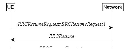
Figure 5.3.13.1-1: RRC connection resume,
successful
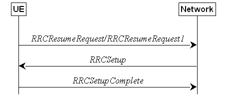
Figure 5.3.13.1-2: RRC connection resume fallback
to RRC connection establishment, successful
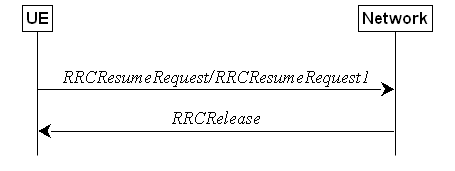
Figure 5.3.13.1-3: RRC connection resume followed
by network release, successful
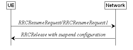
Figure 5.3.13.1-4: RRC connection resume followed
by network suspend, successful
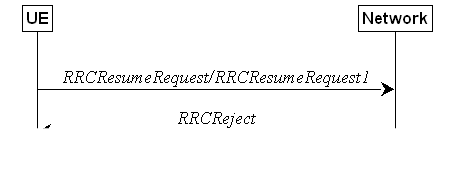
Figure 5.3.13.1-5: RRC connection resume, network
reject
The purpose of this procedure is to resume
a suspended RRC connection, including resuming SRB(s), DRB(s) and multicast
MRB(s) or perform an RNA update. This procedure is also used to initiate SDT in
RRC_INACTIVE.
For NR sidelink communication/positioning/discovery
an RRC connection is resumed only in the following cases:
1> if configured by upper layers to transmit NR
sidelink communication and related data is available for transmission:
2> if the frequency on which the UE is
configured to transmit NR sidelink communication is included in sl-FreqInfoList/sl-FreqInfoListSizeExt
within SIB12 provided by the cell on which the UE camps; and if the valid version of SIB12
does not include sl-TxPoolSelectedNormal for the concerned frequency;
1> if configured by upper layers to transmit NR
sidelink discovery and related data is available for transmission:
2> if the UE is configured by upper layers to
transmit NR sidelink L2 U2N relay discovery messages and sl-L2U2N-Relay
is included in SIB12; or
2> if the UE is configured by upper layers to
transmit NR sidelink L3 U2N relay discovery messages and sl-L3U2N-RelayDiscovery
is included in SIB12; or
2> if the UE is configured by upper layers to
transmit NR sidelink non-relay discovery messages and sl-NonRelayDiscovery
is included in SIB12:
3> if the frequency on which the UE is
configured to transmit NR sidelink discovery is included in sl-FreqInfoList within
SIB12 provided by the cell on which the UE camps; and if the valid
version of SIB12 does not include sl-DiscTxPoolSelected or sl-TxPoolSelectedNormal
for the concerned frequency;
1> if configured by upper layers to perform NR
sidelink positioning and indicated by upper layers to transmit SL-PRS:
2> if the frequency on which the UE is
configured to transmit SL-PRS is included in sl-FreqInfoList/sl-FreqInfoListSizeExt
within SIB12 provided by the cell on which the UE camps; and if the
valid version of SIB12 does not include sl-PRS-ResourcesSharedSL-PRS-RP-r18
in sl-TxPoolSelectedNormal for the concerned frequency; or
2> if the frequency on which the UE is
configured to transmit SL-PRS is included in sl-PosFreqInfoList within SIB23
provided by the cell on which the UE camps; and if the valid version of SIB23
does not include sl-PRS-TxPoolSelectedNormal for the concerned
frequency;
For L2 U2N Relay UE in RRC_INACTIVE, an RRC
connection establishment is resumed in the following cases:
1> if any message is received from the L2 U2N
Remote UE via SL-RLC0 as specified in 9.1.1.4 or SL-RLC1 as specified in 9.2.4; or
1> if RemoteUEInformationSidelink containing the connectionForMP is
received from a L2 U2N Remote UE as specified in 5.8.9.8.3;
For V2X sidelink communication an RRC
connection resume is initiated only when the conditions specified for V2X
sidelink communication in clause 5.3.3.1a of TS 36.331 [10] are met.
NOTE: Upper layers initiate an RRC connection
resume (except if the RRC connection resume is initiated at the L2 U2N Relay UE
upon reception of a message from a L2 U2N Remote UE via SL-RLC0 or SL-RLC1, or
upon reception of RemoteUEInformationSidelink message containing the connectionForMP).
The interaction with NAS is left to UE implementation.
When requesting lower layers to check the
conditions for initiating SDT, RRC indicates to lower layers whether the resume
procedure is initiated for mobile originated or mobile terminated case.
A UE in RRC_INACTIVE initiates the resume
procedure for SDT when all of the following conditions are fulfilled:
1> for the resume procedure initiated by the
upper layers (i.e. mobile originated case):
2> SIB1 includes sdt-ConfigCommon; and
2> sdt-Config is configured; and
2> all the pending data in UL is mapped to the
radio bearers configured for SDT; and
2> for an (e)RedCap UE when RedCap-specific
initial downlink BWP includes no CD-SSB, ncd-SSB-RedCapInitialBWP-SDT is
configured; and
2> lower layers indicate that conditions for
initiating MO-SDT as specified in TS 38.321 [3] are fulfilled.
1> for the resume procedure initiated in
response to RAN paging (i.e. mobile terminated case):
2> lower layers indicate that conditions for
initiating MT-SDT as specified in TS 38.321 [3] are fulfilled.
NOTE: How the UE determines that all pending
data in UL is mapped to radio bearers configured for SDT is left to UE
implementation.
In RRC_INACTIVE state, if configured with
MBS multicast reception in RRC_INACTIVE, the UE shall:
1> if the RRC connection resume procedure is
triggered for multicast reception at reception of SIB1, as specified in
5.2.2.4.2; or
1> if the RRC connection resume procedure is
triggered for multicast reception at reception of Paging message, as
specified in 5.3.2.3; or
1> if the PTM configuration is not available on
the multicast MCCH in the new cell after cell selection (i.e., different from
the cell where the UE was configured to receive multicast in RRC_CONNECTED) or in the cell after cell reselection
for at least one multicast session that the UE has joined and for which the UE
is not indicated to stop monitoring the G-RNTI; or
1> if mbs-NeighbourCellList included in MBSMulticastConfiguration
acquired in the previous cell indicates that at least one multicast session
that the UE has joined and for which the UE is not indicated to stop monitoring
the G-RNTI, is not provided for RRC_INACTIVE in the current serving cell; or
1> if either the measured RSRP or RSRQ for
serving cell as specified in TS 38.304 [20] is below the corresponding threshold
indicated by thresholdIndex for a multicast session that the UE has
joined and for which the UE is not indicated to stop monitoring the G-RNTI:
2> initiate RRC connection resume procedure as
specified in 5.3.13.2 with resumeCause set as below:
3> if the UE is configured by upper layers with
Access Identity 1:
4> set resumeCause to mps-PriorityAccess;
3> else if the UE is configured by upper layers
with Access Identity 2:
4> set resumeCause to mcs-PriorityAccess;
3> else if the UE is configured by upper layers
with one or more Access Identities equal to 11-15:
4> set resumeCause to highPriorityAccess;
3> else:
4> set resumeCause to mt-Access.
The UE initiates the procedure when upper
layers or AS (when responding to RAN paging, upon triggering RNA updates while
the UE is in RRC_INACTIVE, upon requesting multicast reception as specified in
clause 5.3.13.1d, for NR sidelink communication/discovery/V2X sidelink
communication as specified in clause 5.3.13.1a, for requesting configuration
for SRS for positioning, for activation of preconfigured Positioning SRS in
RRC_INACTIVE, for activation of non-preconfigured Positioning SRS with type
semi-persistent in RRC_INACTIVE, upon receiving RRCRelease message including resumeIndication)
requests the resume of a suspended RRC connection or requests the resume for
initiating SDT as specified in clause 5.3.13.1b.
The UE shall ensure having valid and up to
date essential system information as specified in clause 5.2.2.2 before
initiating this procedure.
Upon initiation of the procedure, the UE
shall:
1> if the resumption of the RRC connection is
triggered by response to NG-RAN paging; or
1> if the resumption of the RRC connection is
triggered by receiving RRCRelease message including resumeIndication;
or
1> if the resumption of the RRC connection is
triggered for multicast reception as specified in clause 5.3.13.1d:
2> select '0' as the Access Category;
2> perform the unified access control procedure
as specified in 5.3.14 using the selected Access Category and one or more
Access Identities provided by upper layers;
3> if the access attempt is barred, the
procedure ends;
1> else if the resumption of the RRC connection
is triggered by upper layers:
2> if the upper layers provide an Access
Category and one or more Access Identities:
3> perform the unified access control procedure
as specified in 5.3.14 using the Access Category and Access Identities provided
by upper layers;
4> if the access attempt is barred, the
procedure ends;
2> if the upper layers provide NSAG information
and one or more S-NSSAI(s) triggering the access attempt (TS 23.501 [32] and TS
24.501 [23]):
3> apply the NSAG with highest NSAG priority
among the NSAGs that are included in SIB1 (i.e., in
FeatureCombination and/or in RA-PrioritizationSliceInfo), and that
are associated with the S-NSSAI(s) triggering the access attempt, in the Random
Access procedure (TS 38.321 [3], clause 5.1);
NOTE 0: If there are multiple NSAGs with the
same highest NAS-provided NSAG priority identified for access attempt as above, it is left to UE implementation to select
the NSAG to be applied in the Random Access procedure.
2> if the resumption occurs after release with
redirect with mpsPriorityIndication:
3> set the resumeCause to mps-PriorityAccess;
2> else:
3> set the resumeCause in accordance
with the information received from upper layers;
2> if the resumption of the RRC connection is
triggered for activation of preconfigured SRS for positioning available in srs-PosRRC-InactiveValidityAreaPreConfigList
and if the UE is camped in one of the cells indicated in one of srs-PosConfigValidityArea; or
2> if the resumption of the RRC connection is
triggered due to the need for SRS for positioning configuration and no stored srs-PosRRC-InactiveValidityAreaPreConfigList
for the camped cell exists; or
2> if the resumption of
the RRC connection is triggered due to activation of non-preconfigured
SRS for positioning with type semi-persistent available in srs-PosRRC-InactiveValidityAreaNonPreConfig and
if the UE is camped in the cells indicated in srs-PosConfigValidityArea:
3> if an emergency service is ongoing:
4> select '2' as the Access Category;
4> set the resumeCause to emergency;
3> else:
4> set the resumeCause to srs-PosConfigOrActivationReq;
1> else if the resumption of the RRC connection
is triggered due to an RNA update as specified in 5.3.13.8:
2> if an emergency service is ongoing:
NOTE 1: How the RRC layer in the UE is aware of
an ongoing emergency service is up to UE implementation.
3> select '2' as the Access Category;
3> set the resumeCause to emergency;
2> else:
3> select '8' as the Access Category;
2> perform the unified access control procedure
as specified in 5.3.14 using the selected Access Category and one or more
Access Identities to be applied as specified in TS 24.501 [23];
3> if the access attempt is barred:
4> set the variable pendingRNA-Update to
true;
4> the procedure ends;
1> else if srs-PosRRC-InactiveValidityAreaPreConfigList
or srs-PosRRC-InactiveValidityAreaNonPreConfig is configured:
2> if the resumption of the RRC connection is
triggered due to cell reselection as specified in clause 5.3.13.6:
3> if an emergency service is ongoing:
4> select '2' as the Access Category;
4> set the resumeCause to emergency;
3> else:
4> select '8' as the Access Category;
4> set the resumeCause to srs-PosConfigOrActivationReq;
NOTE 2: In case the L2
U2N Relay UE initiates RRC connection resume triggered either by reception of message from a L2 U2N Remote UE via SL-RLC0
or SL-RLC1 as specified in 5.3.13.1a, or by reception of the RemoteUEInformationSidelink
message containing the connectionForMP as specified in 5.3.13.1a, the L2
U2N Relay UE sets the resumeCause by implementation, but it can only set
the emergency, mps-PriorityAccess, or mcs-PriorityAccess
as resumeCause, if the same cause value in the message
received from the L2 U2N Remote UE via SL-RLC0.
1> if the UE is in NE-DC or NR-DC:
2> if the UE does not support maintaining SCG
configuration upon connection resumption:
3> release the MR-DC related configurations
(i.e., as specified in 5.3.5.10) from the UE Inactive AS context, if stored;
1> if the UE does not support maintaining the
MCG SCell configurations upon connection resumption:
2> release the MCG SCell(s) from the UE
Inactive AS context, if stored;
1> if the UE is acting as L2 U2N Remote UE:
2> establish a SRAP entity as specified in TS
38.351 [66], if no SRAP entity has been established;
2> apply the default configuration of SL-RLC1
as defined in 9.2.4 for SRB1;
2> apply the default PDCP configuration as defined
in 9.2.1 for SRB1;
2> apply the default configuration of SRAP as
defined in 9.2.5 for SRB1;
1> else:
2> apply the default L1 parameter values as
specified in corresponding physical layer specifications, except for the
parameters for which values are provided in SIB1;
2> apply the default SRB1 configuration as
specified in 9.2.1;
2> apply the default MAC Cell Group
configuration as specified in 9.2.2;
1> release delayBudgetReportingConfig from
the UE Inactive AS context, if stored;
1> stop timer T342, if running;
1> release overheatingAssistanceConfig from
the UE Inactive AS context, if stored;
1> stop timer T345, if running;
1> release idc-AssistanceConfig from the
UE Inactive AS context, if stored;
1> release drx-PreferenceConfig for all
configured cell groups from the UE Inactive AS context, if stored;
1> stop all instances of timer T346a, if
running;
1> release maxBW-PreferenceConfig and maxBW-PreferenceConfigFR2-2
for all configured cell groups from the UE Inactive AS context, if stored;
1> stop all instances of timer T346b, if
running;
1> release maxCC-PreferenceConfig for
all configured cell groups from the UE Inactive AS context, if stored;
1> stop all instances of timer T346c, if
running;
1> release maxMIMO-LayerPreferenceConfig
and maxMIMO-LayerPreferenceConfigFR2-2 for all configured cell groups
from the UE Inactive AS context, if stored;
1> stop all instances of timer T346d, if
running;
1> release minSchedulingOffsetPreferenceConfig
and minSchedulingOffsetPreferenceConfigExt for all configured cell
groups from the UE Inactive AS context, if stored;
1> stop all instances of timer T346e, if
running;
1> release rlm-RelaxationReportingConfig for all configured cell
groups from the UE Inactive AS context, if stored;
1> stop all instances of timer T346j, if
running;
1> release bfd-RelaxationReportingConfig for all configured cell
groups from the UE Inactive AS context, if stored;
1> stop all instances of timer T346k, if
running;
1> release releasePreferenceConfig from
the UE Inactive AS context, if stored;
1> release wlanNameList from the UE
Inactive AS context, if stored;
1> release btNameList from the UE
Inactive AS context, if stored;
1> release sensorNameList from the UE
Inactive AS context, if stored;
1> release obtainCommonLocation from the UE Inactive AS
context, if stored;
1> stop timer T346f, if running;
1> stop timer T346i, if running;
1> release referenceTimePreferenceReporting
from the UE Inactive AS context, if stored;
1> release sl-AssistanceConfigNR from
the UE Inactive AS context, if stored;
1> release musim-GapAssistanceConfig
from the UE Inactive AS context, if stored and stop timer T346h, if running;
1> release musim-GapConfig from the UE
Inactive AS context, if stored;
1> release musim-GapPriorityAssistanceConfig
from the UE Inactive AS context, if stored;
1> release musim-LeaveAssistanceConfig
from the UE Inactive AS context, if stored;
1> release musim-CapabilityRestrictionConfig
from the UE Inactive AS context, if stored and stop timer T346n, if
running;
1> release propDelayDiffReportConfig
from the UE Inactive AS context, if stored;
1> release ul-GapFR2-PreferenceConfig,
if configured;
1> release rrm-MeasRelaxationReportingConfig
from the UE Inactive AS context, if stored;
1> release multiRx-PreferenceReportingConfigFR2
if configured, and stop timer T346m, if running;
1> release aerial-FlightPathAvailabilityConfig
from the UE Inactive AS context, if stored;
1> release ul-TrafficInfoReportingConfig
from the UE Inactive AS context, if stored;
1> stop all instances of timer T346l, if running;
1> if the UE is acting as L2 U2N Remote UE:
2> apply the specified configuration of SL-RLC0 used for the delivery of RRC message
over SRB0 as specified in 9.1.1.4;
2> apply the SDAP configuration and PDCP
configuration as specified in 9.1.1.2 for SRB0;
1> else:
2> apply the CCCH configuration as specified in
9.1.1.2;
2> apply the timeAlignmentTimerCommon
included in SIB1;
1> if sdt-MAC-PHY-CG-Config is
configured:
2> if the resume
procedure is initiated in a cell that is different to the PCell in which
the UE received the stored sdt-MAC-PHY-CG-Config:
3> release the stored sdt-MAC-PHY-CG-Config;
3> instruct the MAC entity to stop the cg-SDT-TimeAlignmentTimer,
if it is running;
1> if ncd-SSB-RedCapInitialBWP-SDT is
configured:
2> if the resume procedure is initiated in a
cell that is different to the PCell in which the UE received the stored ncd-SSB-RedCapInitialBWP-SDT:
3> release the stored ncd-SSB-RedCapInitialBWP-SDT;
1> if conditions for initiating SDT in
accordance with 5.3.13.1b are fulfilled:
2> consider the resume procedure is initiated
for SDT;
2> start timer T319a when the lower layers
first transmit the CCCH message;
2> consider SDT procedure is ongoing;
1> else:
2> start timer T319;
2> instruct the MAC entity to stop the cg-SDT-TimeAlignmentTimer,
if it is running;
1> if ta-Report or
ta-ReportATG is configured with value enabled and the UE supports TA
reporting:
2> indicate TA report initiation to lower
layers;
1> set the variable pendingRNA-Update to
false;
1> release successHO-Config from the UE
Inactive AS context, if stored;
1> release successPSCell-Config
configured by the PCell from the UE Inactive AS context, if stored;
1> release successPSCell-Config
configured by the PSCell from the UE Inactive AS context, if stored;
1> initiate transmission of the RRCResumeRequest
message or RRCResumeRequest1 in accordance with 5.3.13.3.
The UE shall set the contents of RRCResumeRequest
or RRCResumeRequest1 message as follows:
1> if useFullResumeID is signalled in SIB1:
2> select RRCResumeRequest1 as the
message to use;
2> set the resumeIdentity to the stored fullI-RNTI
value;
1> else:
2> select RRCResumeRequest as the
message to use;
2> set the resumeIdentity to the stored shortI-RNTI
value;
1> restore the RRC configuration, RoHC state, the
EHC context(s), the UDC state, the stored QoS flow to DRB mapping rules and the
KgNB and KRRCint keys from the stored UE Inactive AS
context except for the following:
- masterCellGroup;
- mrdc-SecondaryCellGroup, if stored; and
- pdcp-Config;
1> set the resumeMAC-I to the 16 least
significant bits of the MAC-I calculated:
2> over the ASN.1 encoded as per clause 8
(i.e., a multiple of 8 bits) VarResumeMAC-Input;
2> with the KRRCint key in the UE
Inactive AS Context and the previously configured integrity protection
algorithm; and
2> with all input bits for COUNT, BEARER and
DIRECTION set to binary ones;
1> derive the KgNB key based on the
current KgNB key or the NH, using the nextHopChainingCount
value received in the
previous RRCRelease message and stored in the UE Inactive AS Context,
as specified in TS 33.501 [11];
1> derive the KRRCenc key, the KRRCint
key, the KUPint key and the KUPenc key;
1> configure lower layers to apply integrity
protection for all radio bearers except SRB0 and MRBs using the configured
algorithm and the KRRCint key and KUPint key derived in
this clause immediately, i.e., integrity protection shall be applied to all
subsequent messages received and sent by the UE;
NOTE 1: Only DRBs with previously configured UP
integrity protection shall resume integrity protection.
1> configure lower layers to apply ciphering
for all radio bearers except SRB0 and MRBs and to apply the configured
ciphering algorithm, the KRRCenc key and the KUPenc key
derived in this clause, i.e. the ciphering configuration shall be applied to
all subsequent messages received and sent by the UE;
1> re-establish PDCP entities for SRB1;
1> resume SRB1;
1> if the resume procedure is initiated for
SDT:
2> for each radio bearer that is configured for
SDT and for SRB1:
3> restore the RLC-BearerConfig associated
with the RLC bearers of masterCellGroup and pdcp-Config from the
UE Inactive AS context;
3> if the radio bearer is a DRB configured with
Ethernet Header Compression:
4> indicate to lower layer that ethernetHeaderCompression
is not configured;
3> if the radio bearer is a DRB configured with
UDC:
4> indicate to lower layer that uplinkDataCompression
is not configured;
3> if the radio bearer is a DRB configured with
ROHC function:
4> if sdt-DRB-ContinueROHC is set to cell
and the resume procedure is initiated in a cell that is the same as the PCell
in which the UE received the previous RRCRelease message; or
4> if sdt-DRB-ContinueROHC is set to rna
and the resume procedure is initiated in a cell belonging to the same RNA as
the PCell in which the UE received the previous RRCRelease message:
5> indicate to lower layer that drb-continueROHC
is configured;
4> else:
5> indicate to lower layer that drb-continueROHC
is not configured;
3> re-establish PDCP entity for the radio
bearer that is configured for SDT without triggering PDCP status report;
2> resume all the radio bearers that are
configured for SDT;
1> submit the selected message RRCResumeRequest
or RRCResumeRequest1 for transmission to lower layers.
NOTE 2: Only DRBs with previously configured UP
ciphering shall resume ciphering.
NOTE 2a: Before the lower layers first transmit
the RRCResumeRequest or RRCResumeRequest1, the UE may initiate a
new resume procedure if other conditions for initiation of the resume procedure
as specified in 5.3.13.2 are satisfied.
If lower layers indicate an integrity check
failure while T319 is running or SDT procedure is ongoing, perform actions
specified in 5.3.13.5.
If the UE is an (e)RedCap UE and the RedCap-specific
initial downlink BWP is not associated with CD-SSB, the UE may continue cell
re-selection related measurements as well as cell re-selection evaluation,
otherwise the UE shall continue cell re-selection related measurements as well
as cell re-selection evaluation. If the conditions for cell re-selection are
fulfilled, the UE shall perform cell re-selection as specified in 5.3.13.6.
NOTE 3: For L2 U2N Remote UE in RRC_INACTIVE, the
cell (re)selection procedure as specified in TS 38.304 [20] and relay
(re)selection procedure as specified in 5.8.15.3 are performed independently
and it is up to UE implementation to select either a cell or a L2 U2N Relay UE.
The UE shall:
1> stop timer T319, if running;
1> stop timer T319a, if running and consider
SDT procedure is not ongoing;
1> stop timer T380, if running;
1> if T331 is running:
2> stop timer T331;
2> perform the actions as specified in 5.7.8.3;
1> if the RRCResume includes the fullConfig:
2> perform the full
configuration procedure as specified in 5.3.5.11;
1> else:
2> if the RRCResume does not include the restoreMCG-SCells:
3> release the MCG SCell(s) from the UE
Inactive AS context, if stored;
2> if the RRCResume does not include the restoreSCG:
3> release the MR-DC related configurations
(i.e., as specified in 5.3.5.10) from the UE Inactive AS context, if stored;
2> restore the masterCellGroup,
mrdc-SecondaryCellGroup, if stored, and pdcp-Config from the UE
Inactive AS context;
2> configure lower layers to consider the
restored MCG and SCG SCell(s) (if any) to be in deactivated state;
1> discard the UE Inactive AS context;
1> store the used nextHopChainingCount
value associated to the current KgNB;
1> if the UE is configured to receive MBS multicast
in RRC_INACTIVE:
2> reset MAC;
1> if sdt-MAC-PHY-CG-Config is
configured:
2> instruct the MAC entity to stop the cg-SDT-TimeAlignmentTimer,
if it is running;
2> instruct the MAC entity to start the timeAlignmentTimer
associated with the PTAG indicated by tag-Id, if it is not running;
1> if srs-PosRRC-Inactive is configured:
2> instruct the MAC entity to stop inactivePosSRS-TimeAlignmentTimer,
if it is running;
1> if srs-PosRRC-InactiveValidityAreaNonPreConfig
is configured; or
1> if srs-PosRRC-InactiveValidityAreaPreConfigList is configured and if the cell is not listed in srs-PosConfigValidityArea:
2> instruct the MAC entity to stop inactivePosSRS-ValidityAreaTAT,
if it is running;
1> release the suspendConfig except the ran-NotificationAreaInfo;
1> if the RRCResume includes the masterCellGroup:
2> perform the cell group configuration for the
received masterCellGroup according to 5.3.5.5;
1> if the RRCResume includes the mrdc-SecondaryCellGroup:
2> if the received mrdc-SecondaryCellGroup
is set to nr-SCG:
3> perform the RRC reconfiguration according to
5.3.5.3 for the RRCReconfiguration message included in nr-SCG;
2> if the received mrdc-SecondaryCellGroup
is set to eutra-SCG:
3> perform the RRC connection reconfiguration as specified in TS 36.331 [10], clause 5.3.5.3 for the RRCConnectionReconfiguration
message included in eutra-SCG;
1> if the RRCResume includes the radioBearerConfig:
2> perform the radio bearer configuration
according to 5.3.5.6;
1> if the RRCResume message includes the sk-Counter:
2> perform security key update procedure as
specified in 5.3.5.7;
1> if the RRCResume message includes the radioBearerConfig2:
2> perform the radio bearer configuration
according to 5.3.5.6;
1> if the RRCResume message includes the needForGapsConfigNR:
2> if needForGapsConfigNR is set to setup:
3> consider itself to be configured to provide the measurement gap requirement information of
NR target bands;
2> else:
3> consider itself not to be configured to provide the measurement gap requirement information of
NR target bands;
1> if the RRCResume message includes the
needForGapNCSG-ConfigNR:
2> if needForGapNCSG-ConfigNR is set to setup:
3> consider itself to be configured to provide the measurement gap and NCSG requirement
information of NR target bands;
2> else:
3> consider itself not to be configured to provide the measurement gap and NCSG requirement
information of NR target bands;
1> if the RRCResume message includes the
needForGapNCSG-ConfigEUTRA:
2> if needForGapNCSG-ConfigEUTRA is set
to setup:
3> consider itself to be configured to provide the measurement gap and NCSG requirement
information of E‑UTRA target bands;
2> else:
3> consider itself not to be configured to provide the measurement gap and NCSG requirement
information of E‑UTRA target bands;
1> for each application layer measurement
configuration with appLayerIdleInactiveConfig configured:
2> if the RPLMN is not included in plmn-IdentityList
in VarAppLayerPLMN-ListConfig:
3> forward the measConfigAppLayerId and
inform upper layers about the release of the application layer measurement
configuration;
3> release the application layer measurement
configuration including its fields in the UE variables VarAppLayerIdleConfig
and VarAppLayerPLMN-ListConfig;
3> discard any application layer measurement
reports which were not yet fully submitted to lower layers for transmission;
3> consider itself not to be configured to send
application layer measurement reports for the measConfigAppLayerId;
1> if the RRCResume message includes the
appLayerMeasConfig:
2> if idleInactiveReportAllowed is
included in the RRCResume message:
3> if the UE is configured with at least one
application layer measurement configuration with appLayerIdleInactiveConfig
configured:
4> initiate the procedure in 5.7.16.2 after the
RRCResumeComplete has been transmitted;
2> else:
3> for each application layer measurement
configuration with appLayerIdleInactiveConfig configured:
4> forward the measConfigAppLayerId and
inform upper layers about the release of the application layer measurement
configuration;
4> release the application layer measurement
configuration including its fields in the UE variables VarAppLayerIdleConfig
and VarAppLayerPLMN-ListConfig, if stored;
4> discard any application layer measurement
reports which were not yet fully submitted to lower layers for transmission;
4> consider itself not to be configured to send
application layer measurement reports for the measConfigAppLayerId;
2> perform the application layer measurement
configuration procedure as specified in 5.3.5.13d;
1> if the RRCResume message includes the
sl-L2RemoteUE-Config (i.e. the UE is a L2 U2N Remote UE):
2> perform the L2 U2N Remote UE configuration
procedure as specified in 5.3.5.16;
1> if the RRCResume message includes the
sl-ConfigDedicatedNR:
2> perform the sidelink dedicated configuration
procedure as specified in 5.3.5.14;
1> resume SRB2 (if suspended), SRB3 (if
configured), SRB4 (if configured), SRB5 (if configured), all DRBs (that are
suspended) and multicast MRBs (that are suspended);
NOTE 1: If the SCG is deactivated, resuming SRB3
and all DRBs does not imply that PDCP or RRC PDUs can be transmitted or
received on SCG RLC bearers.
1> if stored, discard the cell reselection
priority information provided by the cellReselectionPriorities or
inherited from another RAT;
1> stop timer T320, if running;
1> if the RRCResume message includes the
measConfig:
2> perform the measurement configuration
procedure as specified in 5.5.2;
1> resume measurements if suspended;
1> if T390 is running:
2> stop timer T390 for all access categories;
2> perform the actions as specified in
5.3.14.4;
1> if T302 is running:
2> stop timer T302;
2> perform the actions as specified in
5.3.14.4;
1> enter RRC_CONNECTED;
1> indicate to upper layers that the suspended
RRC connection has been resumed;
1> stop the cell re-selection procedure;
1> stop relay reselection procedure if any for
L2 U2N Remote UE;
1> consider the current cell to be the PCell;
1> set the content of the of RRCResumeComplete
message as follows:
2> if the upper layer provides NAS PDU, set the
dedicatedNAS-Message to include the information received from upper
layers;
2> if upper layers provides a PLMN:
3> if the UE is either allowed or instructed to
access the PLMN via a cell for which at least one CAG ID is broadcast:
4> set the selectedPLMN-Identity from
the npn-IdentityInfoList;
3> else:
4> set the selectedPLMN-Identity to the
PLMN selected by upper layers from the plmn-IdentityInfoList;
2> if the masterCellGroup contains the reportUplinkTxDirectCurrent:
3> include the uplinkTxDirectCurrentList for
each MCG serving cell with UL;
3> include uplinkDirectCurrentBWP-SUL
for each MCG serving cell configured with SUL carrier, if any, within the uplinkTxDirectCurrentList;
2> if the masterCellGroup contains the reportUplinkTxDirectCurrentTwoCarrier:
3> include in the uplinkTxDirectCurrentTwoCarrierList
the list of uplink Tx DC locations for the configured uplink carrier
aggregation in the MCG;
2> if the masterCellGroup contains the reportUplinkTxDirectCurrentMoreCarrier:
3> include in the uplinkTxDirectCurrentMoreCarrierList
the list of uplink Tx DC locations for the configured uplink carrier
aggregation in the MCG;
2> if the UE has
idle/inactive measurement information concerning cells other than the PCell
available in VarMeasIdleReport:
3> if the idleModeMeasurementReq is
included in the RRCResume message:
4> if validatedMeasurementsReq is
included in the RRCResume and measIdleValidityDuration is
included in VarEnhMeasIdleConfig;
5> set the measResultIdleEUTRA in the RRCResumeComplete
message to the value of measReportIdleEUTRA in the VarMeasIdleReport for
any valid measurement results, if available, and set validityStatus to
the value of measIdleValidityDuration in VarEnhMeasIdleConfig;
5> set the measResultIdleNR in the RRCResumeComplete
message to the value of measReportIdleNR in the VarMeasIdleReport for
any valid measurement results, if available, and set validityStatus to the
value of measIdleValidityDuration in VarEnhMeasIdleConfig;
5> discard the VarMeasIdleReport upon
successful delivery of the RRCResumeComplete message is confirmed by
lower layers;
4> else:
5> set the measResultIdleEUTRA in the RRCResumeComplete
message to the value of measReportIdleEUTRA in the VarMeasIdleReport, if
available;
5> set the measResultIdleNR in the RRCResumeComplete
message to the value of measReportIdleNR in the VarMeasIdleReport,
if available;
5> discard the VarMeasIdleReport upon
successful delivery of the RRCResumeComplete message is confirmed by
lower layers;
3> else:
4> if the SIB1 contains idleModeMeasurementsNR
and the UE has NR idle/inactive measurement information concerning cells other
than the PCell available in VarMeasIdleReport; or
4> if the SIB1 contains idleModeMeasurementsEUTRA
and the UE has E-UTRA idle/inactive measurement information available in VarMeasIdleReport:
5> include the idleMeasAvailable;
2> if the reselectionMeasurementReq is
included in the RRCResume message:
3> if validatedMeasurementsReq is
included in the RRCResume and measReselectionValidityDuration is
included in VarMeasReselectionConfig:
4> if measReselectionCarrierListNR is
present in VarMeasReselectionConfig:
5> if the UE has valid cell reselection
measurements results for any frequency listed in measReselectionCarrierListNR
in VarMeasRelectionConfig:
6> set the measResultReselectionNR in
the RRCResumeComplete message to the valid NR measurement results, if
available for any frequency listed in measReselectionCarrierListNR in VarMeasReselectionConfig
and set validityStatus to the value of measReselectionValidityDuration
in VarMeasReselectionConfig;
4> else:
5> if the UE has valid NR cell reselection
measurements results:
6> set the measResultReselectionNR in
the RRCResumeComplete message to any available valid NR measurement
results, if available;
3> else:
4> if measReselectionCarrierListNR is
present in VarMeasReselectionConfig:
5> if the UE has cell reselection measurements
results for any frequency listed in measReselectionCarrierListNR in VarMeasRelectionConfig:
6> set the measResultReselectionNR in
the RRCResumeComplete message to the NR measurement results, if
available for any frequency listed in measReselectionCarrierListNR in VarMeasReselectionConfig;
4> else:
5> if the UE has NR cell reselection
measurements results:
6> set the measResultReselectionNR in
the RRCResumeComplete message to any available NR measurement results,
if available;
3> else:
4> if the SIB1 contains reselectionMeasurementsNR:
and the UE has NR reselection measurements available for any
frequency listed in measReselectionCarrierListNR in VarMeasReselectionConfig;
or
5> if measReselectionCarrierListNR is
not present in VarMeasReselectionConfig and if the UE has NR reselection
measurements available:
6> include the reselectionMeasAvailable;
2> if the RRCResume message includes mrdc-SecondaryCellGroup
set to eutra-SCG:
3> include in the eutra-SCG-Response the
E-UTRA RRCConnectionReconfigurationComplete message in accordance with
TS 36.331 [10] clause 5.3.5.3;
2> if the RRCResume message includes mrdc-SecondaryCellGroup
set to nr-SCG:
3> include in the nr-SCG-Response the
SCG RRCReconfigurationComplete message;
2> if the UE has logged measurements available
for NR and if the RPLMN is included in plmn-IdentityList stored in VarLogMeasReport;
or
2> if the UE has logged measurements available
for NR and if the current registered SNPN identity is included in snpn-ConfigID-List
stored in VarLogMeasReport:
3> include the logMeasAvailable in the RRCResumeComplete message;
3> if Bluetooth measurement results are
included in the logged measurements the UE has available for NR:
4> include the logMeasAvailableBT in the RRCResumeComplete message;
3> if WLAN measurement results are included in
the logged measurements the UE has available for NR:
4> include the logMeasAvailableWLAN in the RRCResumeComplete message;
2> if the sigLoggedMeasType
in VarLogMeasReport is included; or
2> if the UE supports the override protection of
the signalling based logged MDT for inter-RAT (i.e. LTE
to NR), and if the sigLoggedMeasType in VarLogMeasReport
of TS 36.331 [10] is included:
3> if T330 timer is running (associated to the
logged measurement configuration for NR or for LTE):
4> set sigLogMeasConfigAvailable to true
in the RRCResumeComplete
message;
3> else:
4> if the UE has logged measurements in VarLogMeasReport
or in VarLogMeasReport of TS 36.331 [10]:
5> set sigLogMeasConfigAvailable to false
in the RRCResumeComplete message;
2> if the UE has connection establishment
failure or connection resume failure information available in VarConnEstFailReport
or VarConnEstFailReportList and if the RPLMN is equal to plmn-Identity stored in VarConnEstFailReport
or in at least one of the entries of VarConnEstFailReportList; or
2> if the UE has connection establishment
failure information or connection resume failure information available in VarConnEstFailReport
or VarConnEstFailReportList and if the registered SNPN identity is
equal to snpn-Identity in networkIdentity stored in VarConnEstFailReport
or any entry of VarConnEstFailReportList:
3> include connEstFailInfoAvailable in the RRCResumeComplete message;
2> if the UE has radio link failure or handover
failure information available in VarRLF-Report and if the RPLMN is
included in plmn-IdentityList stored in VarRLF-Report; or
2> if the UE has radio link failure or handover
failure information available in VarRLF-Report of TS 36.331 [10] and if
the UE is capable of cross-RAT RLF reporting and if the RPLMN is included in
plmn-IdentityList stored in VarRLF-Report of TS 36.331 [10]; or
2> if the UE has radio link failure or handover
failure information available in VarRLF-Report and if the current registered SNPN identity are included in snpn-IdentityList
stored in VarRLF-Report;
or
3> include rlf-InfoAvailable in the RRCResumeComplete
message;
2> if the UE has successful PSCell change or
addition related information available in VarSuccessPSCell-Report and if
the RPLMN is included in plmn-IdentityList stored in VarSuccessPSCell-Report;
or
2> if the UE has successful PSCell change or
addition information available in VarSuccessPSCell-Report and if the current registered SNPN identity is included in snpn-IdentityList
stored in the VarSuccessPSCell-Report:
3> include successPSCell-InfoAvailable in the RRCResumeComplete message;
2> if the UE has successful handover
information available in VarSuccessHO-Report and if the RPLMN is
included in plmn-IdentityList stored in VarSuccessHO-Report; or
2> if the UE has successful handover
information available in VarSuccessHO-Report and if the current registered SNPN identity is included in snpn-IdentityList
stored in the VarSuccessHO-Report:
3> include successHO-InfoAvailable in the RRCResumeComplete
message;
2> if the UE supports storage of mobility
history information and the UE has mobility history information available in VarMobilityHistoryReport:
3> include the mobilityHistoryAvail in the RRCResumeComplete message;
2> if speedStateReselectionPars is
configured in the SIB2:
3> include the mobilityState in the RRCResumeComplete message and set it to the mobility state (as specified in TS 38.304
[20]) of the UE just prior to entering RRC_CONNECTED state;
2> if the UE has at least one stored
application layer measurement configuration with appLayerIdleInactiveConfig
configured:
3> include measConfigReportAppLayerAvailable
in the RRCResumeComplete message;
2> if the UE is configured to provide the
measurement gap requirement information of NR target bands:
3> include the NeedForGapsInfoNR
and set the contents as follows:
4> include intraFreq-needForGap and set
the gap requirement information of intra-frequency measurement for each NR
serving cell;
4> if requestedTargetBandFilterNR is
configured, for each supported NR band that is also included in requestedTargetBandFilterNR,
include an entry in interFreq-needForGap and set the gap requirement
information for that band; otherwise, include an entry in interFreq-needForGap
and set the corresponding gap requirement information for each supported NR
band;
3> if the needForInterruptionConfigNR is
enabled:
4> include the needForInterruptionInfoNR
and set the contents as follows:
5> include intraFreq-needForInterruption
with the same number of entries, and listed in the same order, as in intraFreq-needForGap;
5> for each entry in intraFreq-needForInterruption:
6> include interruptionIndication and
set the interruption requirement information if the corresponding entry in intraFreq-needForGap
is set to no-gap;
5> include interFreq-needForInterruption with
the same number of entries, and listed in the same order, as in interFreq-needForGap;
5> for each entry in interFreq-needForInterruption:
6> include interruptionIndication and
set the interruption requirement information if the corresponding entry in interFreq-needForGap
is set to no-gap;
2> if the UE is
configured to provide the measurement gap and NCSG requirement information of
NR target bands:
3> include the NeedForGapNCSG-InfoNR
and set the contents as follows:
4> include intraFreq-needForNCSG and set
the gap and NCSG requirement information of intra-frequency measurement for
each NR serving cell;
4> if requestedTargetBandFilterNCSG-NR
is configured:
5> for each supported NR band included in requestedTargetBandFilterNCSG-NR,
include an entry in interFreq-needForNCSG and set the NCSG requirement
information for that band;
4> else:
5> include an entry for each supported NR band
in interFreq-needForNCSG and set the corresponding NCSG requirement
information;
2> if the UE is
configured to provide the measurement gap and NCSG requirement information of E‑UTRA
target bands:
3> include the NeedForGapNCSG-InfoEUTRA
and set the contents as follows:
4> if requestedTargetBandFilterNCSG-EUTRA
is configured:
5> for each supported E-UTRA band included in requestedTargetBandFilterNCSG-EUTRA,
include an entry in needForNCSG-EUTRA and set the NCSG requirement
information for that band;
4> else:
5> include an entry for each supported E-UTRA
band in needForNCSG-EUTRA and set the corresponding NCSG requirement
information;
2> if SIB1 contains musim-CapRestrictionAllowed:
3> if supported, include the musim-CapRestrictionInd in the RRCResumeComplete
message upon determining it has temporary capability
restriction;
2> if the UE has flight path information
available:
3> include flightPathInfoAvailable;
1> submit the RRCResumeComplete message
to lower layers for transmission;
1> the procedure ends.
NOTE 2: Network only configures at most one of reportUplinkTxDirectCurrent,
reportUplinkTxDirectCurrentTwoCarrier or reportUplinkTxDirectCurrentMoreCarrier
in one RRC message.
NOTE 3: Upon reception of musim-CapRestrictionInd
in RRCResumeComplete, it is up to network implementation to configure
the UE with a limited configuration that is used until network sends RRCReconfiguration
based on the actual restricted UE capabilities included in UEAssistanceInformation.
The UE shall:
1> if timer T319 expires:
2> if the UE supports multiple CEF report:
3> if UE is not in SNPN access mode and if the
UE has connection establishment failure information or connection resume
failure information available in VarConnEstFailReport and if the RPLMN
is equal to plmn-identity in networkIdentity stored in VarConnEstFailReport;
or
3> if the UE is in SNPN access mode and if the
UE has connection establishment failure information or connection resume
failure information available in VarConnEstFailReport and if the
registered SNPN identity is equal to snpn-identity in networkIdentity
stored in VarConnEstFailReport:
4> if the cell identity of current cell is not
equal to the cell identity stored in measResultFailedCell in VarConnEstFailReport and if the maxCEFReport-r17 has not been
reached:
5> append the VarConnEstFailReport as a new entry in the
VarConnEstFailReportList;
2> if the UE is not in
SNPN access mode and if the UE has connection establishment
failure information or connection resume failure information available in VarConnEstFailReport
and if the RPLMN is not equal to plmn-identity stored in VarConnEstFailReport;
or
2> if the UE is in SNPN access mode and if the
UE has connection establishment failure information or connection resume
failure information available in VarConnEstFailReport and if the
registered SNPN identity is not equal to snpn-identity in networkIdentity
stored in VarConnEstFailReport; or
2> if the cell identity of current cell is not
equal to the cell identity stored in measResultFailedCell in VarConnEstFailReport:
3> reset the numberOfConnFail to 0;
2> if the UE supports multiple CEF report and if
the UE has connection establishment failure information or connection resume
failure information available in VarConnEstFailReportList and if the
RPLMN is not equal to plmn-identity in networkIdentity stored in any
entry of VarConnEstFailReportList:
2> if the UE supports multiple CEF report and
if the UE has connection establishment failure information or connection resume
failure information available in VarConnEstFailReportList and if the
registered SNPN identity is not equal to snpn-identity in networkIdentity
stored in any entry of VarConnEstFailReportList:
3> clear the content included in VarConnEstFailReportList;
2> clear the content included in VarConnEstFailReport
except for the numberOfConnFail, if any;
2> store the following connection resume
failure information in the VarConnEstFailReport by setting its fields as
follows:
3> if the UE is not in SNPN access mode:
4> set the plmn-Identity to the PLMN
selected by upper layers (see TS 24.501 [23]) from the PLMN(s) included in the plmn-IdentityInfoList
in SIB1;
3> else if the UE is in SNPN access mode:
4> set the snpn-Identity in networkIdentity to include the SNPN
identity selected by upper layers (see TS 24.501 [23]) from the list of SNPN(s)
included in the npn-IdentityInfoList in SIB1;
3> set the measResultFailedCell
to include the global cell
identity, tracking area code, the cell level and SS/PBCH block level RSRP, and
RSRQ, and SS/PBCH block indexes, of the failed cell based on the available SSB
measurements collected up to the moment the UE detected connection resume
failure;
3> if available, set the measResultNeighCells,
in order of decreasing ranking-criterion as used for cell re-selection, to
include neighbouring cell measurements for at most the following number of
neighbouring cells: 6 intra-frequency and 3 inter-frequency neighbours per
frequency as well as 3 inter-RAT neighbours, per frequency/ set of frequencies
per RAT and according to the following:
4> for each neighbour cell included, include
the optional fields that are available;
NOTE: The UE includes the latest results of
the available measurements as used for cell reselection evaluation, which are
performed in accordance with the performance requirements as specified in TS
38.133 [14].
3> if available, set the locationInfo as
in 5.3.3.7;
3> set perRAInfoList to indicate the performed random access procedure related information
as specified in 5.7.10.5;
3> if numberOfConnFail
is smaller than 8:
4> increment the numberOfConnFail
by 1;
2> perform the actions upon going to RRC_IDLE
as specified in 5.3.11 with release cause 'RRC Resume failure'.
1> else if upon receiving integrity check failure indication from lower layers
while T319 is running:
2> perform the actions upon going to RRC_IDLE
as specified in 5.3.11 with release cause 'RRC Resume failure'.
1> else if indication from the MCG RLC that the maximum number of
retransmissions has been reached is received while SDT procedure is ongoing; or
1> if random access problem indication is
received from MCG MAC while SDT procedure is ongoing; or
1> if the lower layers
indicate that cg-SDT-TimeAlignmentTimer or the configuredGrantTimer
expired before receiving network response for the UL CG-SDT transmission with
CCCH message while SDT procedure is ongoing; or
1> if integrity check failure indication is
received from lower layers while SDT procedure is ongoing; or
1> if T319a expires:
2> consider SDT procedure is not ongoing;
2> perform the actions upon going to RRC_IDLE
as specified in 5.3.11 with release cause 'RRC Resume failure'.
The UE may discard the connection resume
failure or connection establishment failure information, i.e. release the UE
variable VarConnEstFailReport and the UE variable VarConnEstFailReportList,
48 hours after the last connection resume failure is detected.
The L2 U2N Relay UE either indicates to
upper layers (to trigger PC5 unicast link release) or sends NotificationMessageSidelink
message to the connected L2 U2N Remote UE(s) in accordance with 5.8.9.10.
The UE shall:
1> if cell reselection occurs while T319 or
T302 is running or while SDT procedure is ongoing; or
1> if relay (re)selection or cell selection by
a L2 U2N Remote UE occurs while T319 is running; or
1> if cell changes due to relay reselection or
cell selection by a L2 U2N Remote UE while T302 is running:
2> perform the actions upon going to RRC_IDLE
as specified in 5.3.11 with release cause 'RRC Resume failure';
1> else if cell selection or reselection occurs
while T390 is running, or cell change due to relay selection or reselection
occurs while T390 is running:
2> stop T390 for all access categories;
2> perform the actions as specified in
5.3.14.4.
1> else if cell
reselection occurs when srs-PosRRC-Inactive is configured:
2> indicate to the lower layer to stop inactivePosSRS-TimeAlignmentTimer;
2> release the srs-PosRRC-Inactive.
1> else if cell reselection occurs when srs-PosRRC-InactiveValidityAreaPreConfigList
or srs-PosRRC-InactiveValidityAreaNonPreConfig is configured and if
there is an on-going SRS for positioning transmission procedure in
RRC_INACTIVE:
2> if the selected cell is not included in the srs-PosConfigValidityArea:
3> indicate to the lower layer to stop inactivePosSRS-ValidityAreaTAT;
3> initiate RRC connection resume procedure in
5.3.13.2;
2> else if the cell is included in the srs-PosConfigValidityArea:
3> if the selected cell and the previously
camped cell are in the same srs-PosConfigValidityArea:
4> if autonomousTA-AdjustmentEnabled is
configured and if the Timing Advance validation requirements specified in
clause 5.6.6.3 of TS 38.133 [14] is met:
5> indicate to the lower layer to update Timing
Advance and stored RSRP;
4> instruct lower layers to continue
transmitting SRS if Timing Advance validation condition as specified in TS
38.321 [3] are satisfied;
3> if the selected cell and previously camped
cell are in the different srs-PosConfigValidityArea:
4> initiate RRC connection resume procedure in
5.3.13.2;
4> indicate to the lower layer to stop inactivePosSRS-ValidityAreaTAT.
The UE shall:
1> perform the RRC connection setup procedure
as specified in 5.3.3.4.
In RRC_INACTIVE state, the UE shall:
1> if T380 expires; or
1> if RNA Update is triggered at reception of
SIB1, as specified in 5.2.2.4.2:
2> if T319 is not running and SDT procedure is
not ongoing:
3> initiate RRC connection resume procedure in
5.3.13.2 with resumeCause set to rna-Update;
1> if barring is alleviated for Access Category
'8' or Access Category '2', as specified in 5.3.14.4:
2> if upper layers do not request RRC the
resumption of an RRC connection, and
2> if the variable pendingRNA-Update is
set to true:
3> initiate RRC connection resume procedure in
5.3.13.2 with resumeCause value set to rna-Update.
If the UE in RRC_INACTIVE state fails to
find a suitable cell and camps on the acceptable cell to obtain limited service
as defined in TS 38.304 [20], the UE shall:
1> perform the actions upon going to RRC_IDLE
as specified in 5.3.11 with release cause 'other'.
NOTE: It is left to UE implementation how to
behave when T380 expires while the UE is camped neither on a suitable nor on an
acceptable cell.
The UE shall:
1> perform the actions as specified in 5.3.8.
The UE shall:
1> perform the actions as specified in 5.3.15.
5.3.13.11 Inability to comply with RRCResume
The UE shall:
1> if the UE is unable to comply with (part of)
the configuration included in the RRCResume message;
2> perform the actions upon going to RRC_IDLE
as specified in 5.3.11 with release cause ′RRC Resume failure′.
NOTE 1: The UE may apply above failure handling
also in case the RRCResume message causes a protocol error for which the
generic error handling as defined in 10 specifies that the UE shall ignore the
message.
NOTE 2: If the UE is configured (i.e., via SIB1)
to send MUSIM temporary capability restriction indication, and if the UE
supports MUSIM temporary capability restriction, the UE does not apply above
failure handling in case the UE is unable to apply (part of) the configuration resulting
from RRCResume message due to UE temporary capability restriction for MUSIM operation. If UE does not go to
RRC_IDLE in this case, UE still considers the configuration resulting from the RRCResume
message as the current configuration as the baseline for delta configuration
for future reconfigurations. It is up to UE implementation how to apply RRCResume
message. For other cases, if the UE is unable to comply with part of the
configuration, it does not apply any (part of) the configuration, i.e. there is
no partial success/failure.
Upon reselecting to an inter-RAT cell, the
UE shall:
1> perform the actions upon going to RRC_IDLE
as specified in 5.3.11, with release cause 'other'.
The purpose of this procedure is to perform
access barring check for an access attempt associated with a given Access
Category and one or more Access Identities upon request from upper layers
according to TS 24.501 [23] or
the RRC layer. This procedure does not apply to IAB-MT and NCR-MT. This
procedure does not apply to L2 U2N Relay UE initiating RRC connection
establishment or RRC connection resume upon reception of any message from a L2
U2N remote UE via SL-RLC0 or SL-RLC1 in accordance to 5.3.3.1a or 5.3.13.1a.
After a PCell change in RRC_CONNECTED the
UE shall defer access barring checks until it has obtained SIB1 (as
specified in 5.2.2.2) from the target cell.
Upon initiation of the procedure, the UE
shall:
1> if timer T390 is running for the Access
Category:
2> consider the access attempt as barred;
1> else if timer T302 is running:
2> if the Access Category is neither '2' nor
'0';
or
2> if the Access Category is '0' for RRC
resumption triggered by multicast reception as specified in 5.3.13.2:
3> consider the access attempt as barred;
1> else:
2> if the Access Category is '0':
3> consider the access attempt as allowed;
2> else:
3> if SIB1 includes uac-BarringPerPLMN-List
that contains a UAC-BarringPerPLMN for the selected PLMN or SNPN:
4> if the procedure in 5.2.2.4.2 for a selected
PLMN resulted in use of information in npn-IdentityInfoList and UAC-BarringPerPLMN
has an entry with the plmn-IdentityIndex corresponding to used
information in this list:
5> select the UAC-BarringPerPLMN entry
with the plmn-IdentityIndex corresponding to used information in the npn-IdentityInfoList;
4> else:
5> select the UAC-BarringPerPLMN entry
with the plmn-IdentityIndex corresponding to the selected PLMN and the PLMN-IdentityInfo,
if any, or the selected SNPN and the npn-IdentityInfoList;
3> if any UAC-BarringPerPLMN entry is
selected:
4> in the remainder of this procedure, use the
selected UAC-BarringPerPLMN entry (i.e. presence or absence of access
barring parameters in this entry) irrespective of the uac-BarringForCommon
included in SIB1;
3> else if SIB1 includes uac-BarringForCommon:
4> in the remainder of this procedure use the uac-BarringForCommon
(i.e. presence or absence of these parameters) included in SIB1;
3> else:
4> consider the access attempt as allowed;
3> if uac-BarringForCommon
is applicable or the uac-ACBarringListType
indicates that uac-ExplicitACBarringList is used:
4> if the corresponding UAC-BarringPerCatList
contains a UAC-BarringPerCat entry corresponding to the Access Category:
5> select the UAC-BarringPerCat entry;
5> if the uac-BarringInfoSetList
contains a UAC-BarringInfoSet entry corresponding to the selected uac-barringInfoSetIndex
in the UAC-BarringPerCat:
6> select the UAC-BarringInfoSet entry;
6> perform access barring check for the Access
Category as specified in 5.3.14.5, using the selected UAC-BarringInfoSet
as "UAC barring parameter";
5> else:
6> consider the access attempt as allowed;
4> else:
5> consider the access
attempt as allowed;
3> else if the uac-ACBarringListType
indicates that uac-ImplicitACBarringList is used:
4> select the uac-BarringInfoSetIndex corresponding to the
Access Category in the uac-ImplicitACBarringList;
4> if the uac-BarringInfoSetList
contains the UAC-BarringInfoSet entry corresponding to the selected uac-BarringInfoSetIndex:
5> select the UAC-BarringInfoSet entry;
5> perform access barring check for the Access
Category as specified in 5.3.14.5, using the selected UAC-BarringInfoSet
as "UAC barring parameter";
4> else:
5> consider the access attempt as allowed;
3> else:
4> consider the access attempt as allowed;
1> if the access barring check was requested by upper layers:
2> if the access attempt
is considered as barred:
3> if timer T302 is running:
4> if timer T390 is running for Access Category
'2':
5> inform the upper layer that access barring
is applicable for all access categories except categories '0', upon which the
procedure ends;
4> else
5> inform the upper layer that access barring
is applicable for all access categories except categories '0' and '2', upon
which the procedure ends;
3> else:
4> inform upper layers that the access attempt
for the Access Category is barred, upon which the procedure ends;
2> else:
3> inform upper layers that the access attempt
for the Access Category is allowed, upon which the procedure ends;
1> else:
2> the procedure ends.
The UE shall:
1> if timer T302 expires or is stopped:
2> for each Access Category for which T390 is
not running:
3> consider the barring for this Access
Category to be alleviated:
1> else if timer T390 corresponding to an
Access Category other than '2' expires or is stopped, and if timer T302 is not
running:
2> consider the barring for this Access
Category to be alleviated;
1> else if timer T390 corresponding to the
Access Category '2' expires or is stopped:
2> consider the barring for this Access
Category to be alleviated;
1> when barring for an Access Category is
considered being alleviated:
2> if the Access Category was informed to upper
layers as barred:
3> inform upper layers about barring
alleviation for the Access Category.
2> else if the Access Category is Access
Category '0' for RRC resumption triggered by multicast reception as specified
in 5.3.13.2:
3> perform actions specified in 5.3.13.1d;
2> if barring is alleviated for Access Category
'8'; or
2> if barring is alleviated for Access Category
'2':
3> perform actions specified in 5.3.13.8;
The UE shall:
1> if one or more Access Identities equal to 1,
2, 11, 12, 13, 14, or 15 are indicated according to TS 24.501 [23], and
1> if for at least one of these Access
Identities the corresponding bit in the uac-BarringForAccessIdentity
contained in "UAC barring parameter" is set to zero:
2> consider the access attempt as allowed;
1> else:
2> if the establishment of the RRC connection
is the result of release with redirect with mpsPriorityIndication (either
in NR or E-UTRAN); and
2> if the bit corresponding to Access Identity
1 in the uac-BarringForAccessIdentity contained in the "UAC barring
parameter" is set to zero:
3> consider the access attempt as allowed;
2> else if Access Identity 3 is indicated:
3> draw a random number 'rand' uniformly
distributed in the range: 0 ≤ rand < 1;
3> if 'rand' is lower than the value
indicated by uac-BarringFactorForAI3 included in "UAC barring
parameter":
4> consider the access attempt as allowed;
3> else:
4> consider the access attempt as barred;
2> else:
3> draw a random number 'rand' uniformly
distributed in the range: 0 ≤ rand < 1;
3> if 'rand' is lower than the value
indicated by uac-BarringFactor included in "UAC barring
parameter":
4> consider the access attempt as allowed;
3> else:
4> consider the access attempt as barred;
1> if the access attempt is considered as
barred:
2> draw a random number 'rand' that is
uniformly distributed in the range 0 ≤ rand < 1;
2> start timer T390 for the Access Category
with the timer value calculated as follows, using the uac-BarringTime
included in "UAC barring parameter":
T390 = (0.7+ 0.6 * rand) *
uac-BarringTime.
The UE initiates the procedure upon the
reception of RRCReject when the UE tries to establish or resume an RRC
connection.
The UE shall:
1> stop timer T300, if running;
1> stop timer T319, if running;
1> stop timer T319a, if running and consider
SDT procedure is not ongoing;
1> stop timer T302, if running;
1> reset MAC and release the default MAC Cell
Group configuration (except if the RRCReject is received in response to
resuming RRC connection for multicast reception);
1> if waitTime is configured in the RRCReject:
2> start timer T302, with the timer value set
to the waitTime;
1> if RRCReject is received in response
to a request from upper layers:
2> inform the upper layer that access barring
is applicable for all access categories except categories '0' and '2';
1> if RRCReject is received in response
to an RRCSetupRequest:
2> inform upper layers about the failure to
setup the RRC connection, upon which the procedure ends;
1> else if RRCReject is received in
response to an RRCResumeRequest or an RRCResumeRequest1:
2> if resume is triggered by upper layers:
3> inform upper layers about the failure to
resume the RRC connection;
2> if resume is triggered due to an RNA
update; or
2> if resume is triggered for SDT and T380 has
expired:
3> set the variable pendingRNA-Update to
true;
2> discard the current KgNB key, the
KRRCenc key, the KRRCint key, the KUPint key
and the KUPenc key derived in accordance with 5.3.13.3;
2> if resume is triggered for SDT:
3> for SRB2, if it is resumed and for SRB1:
4> trigger the PDCP entity to perform SDU
discard as specified in TS 38.323 [5];
4> re-establish the RLC entity as specified in
TS 38.322 [4];
3> for each DRB that is not suspended:
4> indicate PDCP suspend to lower layers;
4> re-establish the RLC entity as specified in
TS 38.322 [4];
2> suspend SRB1 and the radio bearers
configured for SDT, if any;
2> the procedure ends.
Upon L2 U2N Relay UE receives RRCReject,
it either indicates to upper layers (to trigger PC5 unicast link release) or
sends NotificationMessageSidelink message to the connected L2 U2N Remote
UE(s) in accordance with 5.8.9.10.
The RRC_INACTIVE UE shall continue to
monitor paging while the timer T302 is running.
NOTE: If timer T331 is running, the UE
continues to perform idle/inactive measurements according to 5.7.8.
Network controlled inter-RAT mobility
between NR and E-UTRA, where E-UTRA can be connected to either EPC or 5GC, and
from NR to UTRA-FDD is supported.
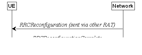
Figure 5.4.2.1-1: Handover to NR, successful
The purpose of this procedure is to, under
the control of the network, transfer a connection between the UE and another
Radio Access Network (e.g. E-UTRAN) to NR.
The handover to NR procedure applies when
SRBs, possibly in combination with DRBs, are established in another RAT.
Handover from E-UTRA to NR applies only after integrity has been activated in
E-UTRA.
The RAN using another RAT initiates the
handover to NR procedure, in accordance with the specifications applicable for
the other RAT, by sending the RRCReconfiguration message via the radio
access technology from which the inter-RAT handover is performed.
The network applies the procedure as
follows:
- to activate ciphering, possibly using NULL
algorithm, if not yet activated in the other RAT;
- to re-establish SRBs and one or more DRBs;
The UE shall:
1> apply the default L1 parameter values as
specified in corresponding physical layer specifications except for the
parameters for which values are provided in SIB1;
1> apply the default MAC Cell Group
configuration as specified in 9.2.2;
1> perform RRC reconfiguration procedure as
specified in 5.3.5;
NOTE: If the UE is connected to 5GC of the
source E-UTRA cell, the delta configuration for PDCP and SDAP can be used for
intra-system inter-RAT handover. For other cases, source RAT configuration is
not considered when the UE applies the reconfiguration message of target RAT.
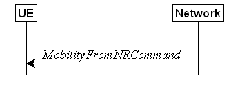
Figure 5.4.3.1-1: Mobility from NR, successful
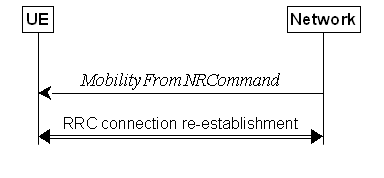
Figure 5.4.3.1-2: Mobility from NR, failure
The purpose of this procedure is to move a
UE in RRC_CONNECTED to a cell using other RAT, e.g. E-UTRA, UTRA-FDD. The mobility from NR procedure
covers the following type of mobility:
- handover, i.e. the MobilityFromNRCommand
message includes radio resources that have been allocated for the UE in the
target cell;
The network initiates the mobility from NR
procedure to a UE in RRC_CONNECTED, possibly in response to a MeasurementReport
or an MCGFailureInformation message, by sending a MobilityFromNRCommand
message. The network applies the procedure as follows:
- the procedure is initiated only when AS
security has been activated, and SRB2 with at least one DRB or multicast MRB have been setup and not suspended;
- the procedure is not initiated if any DAPS
bearer is configured;
The UE shall:
1> stop
timer T310, if running;
1> stop
timer T312, if running;
1> if T316 is running:
2> stop timer T316;
2> if the UE supports RLF-Report
for fast MCG recovery procedure as specified in 38.306
[26]:
3> set the elapsedTimeT316 in the VarRLF-Report
to the value of the elapsed time of the timer T316;
3> set the pSCellId in the VarRLF-Report
to the global cell identity of the PSCell, if available, otherwise to the
physical cell identity and carrier frequency of the PSCell;
2> else:
3> clear the information included in VarRLF-Report,
if any;
1> if T390 is running:
2> stop timer T390 for all access categories;
2> perform the actions as specified in
5.3.14.4;
1> if the targetRAT-Type is set to eutra:
2> consider inter-RAT mobility as initiated towards
E-UTRA;
2> forward the nas-SecurityParamFromNR
to the upper layers, if included;
1> else if the targetRAT-Type is set to utra-fdd:
2> consider inter-RAT mobility as initiated
towards UTRA-FDD;
2> forward the nas-SecurityParamFromNR
to the upper layers, if included;
1> access the target cell indicated in the
inter-RAT message in accordance with the specifications of the target RAT.
Upon successfully completing the handover,
at the source side the UE shall:
1> if T316 was not running at the time of
receiving MobilityFromNRCommand and if the UE was configured with successHO-Config
when connected to the source PCell and the targetRAT-Type
is set to eutra:
2> perform the actions for the successful
handover report determination for inter-RAT handover as specified in clause
5.7.10.6.
1> reset MAC;
1> stop all timers that are running except T325,
T330 and T400;
1> release ran-NotificationAreaInfo, if
stored;
1> release the AS security context including
the KRRCenc key, the KRRCint key, the KUPint
key and the KUPenc key, if stored;
1> release all radio resources, including
release of the RLC entity and the MAC configuration;
1> release the associated PDCP entity and SDAP
entity for all established RBs;
NOTE : PDCP and SDAP configured by the source
RAT prior to the handover that are reconfigured and re-used by target RAT when
delta signalling (i.e., during inter-RAT intra-system handover when fullConfig
is not present) is used, are not released as part of this procedure.
1> if the UE is configured with any application
layer measurement configuration:
2> inform upper layers about the release of all
application layer measurement configurations;
2> release all application layer measurement
configurations including their fields in UE variables VarAppLayerIdleConfig
and VarAppLayerPLMN-ListConfig;
2> discard any application layer measurement
reports which were not yet fully submitted to lower layers for transmission;
2> consider itself not to be configured to send
application layer measurement reports;
1> if the targetRAT-Type is set to eutra
and the nas-SecurityParamFromNR is included: or
1> if the targetRAT-Type is set to utra-fdd:
2> indicate the release of the RRC connection
to upper layers together with the release cause 'other'.
The UE shall:
1> if the UE does not succeed in establishing
the connection to the target radio access technology:
2> if the targetRAT-Type in the received
MobilityFromNRCommand is set to eutra and the UE supports Radio
Link Failure Report for Inter-RAT MRO EUTRA:
3> store handover failure information in VarRLF-Report
according to 5.3.10.5;
2> if voiceFallbackIndication is
included in the MobilityFromNRCommand message; or
2> if the mobility from NR procedure is for
emergency services fallback as specified in TS 23.502 [43]:
3> attempt to select an E-UTRA cell:
4> if a suitable E-UTRA cell is selected; or
4> if no suitable E-UTRA cell is available and
an acceptable E-UTRA cell supporting emergency call is selected when the UE has
an ongoing emergency call:
5> perform the actions upon going to RRC_IDLE
as specified in 5.3.11, with release cause 'RRC connection failure';
4> else:
5> revert back to the configuration used in the
source PCell;
5> initiate the connection re-establishment
procedure as specified in clause 5.3.7;
NOTE: It is left to UE implementation to
determine whether the mobility from NR procedure is for emergency services
fallback as specified in TS 23.502 [43].
2> else:
3> revert back to the configuration used in the
source PCell;
3> initiate the connection re-establishment
procedure as specified in clause 5.3.7;
1> else if the UE is unable to comply with any
part of the configuration included in the MobilityFromNRCommand message;
or
1> if there is a protocol error in the inter
RAT information included in the MobilityFromNRCommand message, causing
the UE to fail the procedure according to the specifications applicable for the
target RAT:
2> if the targetRAT-Type in the received
MobilityFromNRCommand is set to eutra and the UE supports Radio
Link Failure Report for Inter-RAT MRO EUTRA:
3> store handover failure information in VarRLF-Report
according to 5.3.10.5;
2> revert back to the configuration used in the
source PCell;
2> initiate the connection re-establishment
procedure as specified in clause 5.3.7.
The network may configure an RRC_CONNECTED
UE to perform measurements. The network may configure the UE to report them in
accordance with the measurement configuration or perform conditional
reconfiguration evaluation in accordance with the conditional reconfiguration.
The measurement configuration is provided by means of dedicated signalling i.e.
using the RRCReconfiguration or RRCResume.
The network may configure the UE to perform
the following types of measurements:
- NR measurements;
- Inter-RAT measurements of E-UTRA frequencies;
- Inter-RAT measurements of UTRA-FDD
frequencies;
- NR sidelink measurements of L2 U2N Relay UEs.
The network may configure the UE to report
the following measurement information based on SS/PBCH block(s):
- Measurement results per SS/PBCH block;
- Measurement results per cell based on SS/PBCH
block(s);
- SS/PBCH block(s) indexes.
The network may configure the UE to report
the following measurement information based on CSI-RS resources:
- Measurement results per CSI-RS resource;
- Measurement results per cell based on CSI-RS
resource(s);
- CSI-RS resource measurement identifiers.
The network may configure the UE to perform
the following types of measurements for NR sidelink and V2X sidelink:
- CBR measurements.
The network may configure the UE to report
the following CLI measurement information based on SRS resources:
- Measurement results per SRS resource;
- SRS resource(s) indexes.
The network may configure the UE to report
the following CLI measurement information based on CLI-RSSI resources:
- Measurement results per CLI-RSSI resource;
- CLI-RSSI resource(s) indexes.
The network may configure the UE to report
the following Rx-Tx time difference measurement information based on CSI-RS for
tracking or PRS:
- UE Rx-Tx time difference measurement result.
The measurement configuration includes the
following parameters:
1. Measurement objects: A list of objects on which the UE shall perform the measurements.
- For intra-frequency and inter-frequency
measurements a measurement object indicates the frequency/time location and
subcarrier spacing of reference signals to be measured. Associated with this
measurement object, the network may configure a list of cell specific offsets,
a list of 'exclude-listed' cells and a list of 'allow-listed' cells. Exclude-listed
cells are not applicable in event evaluation or measurement reporting. Allow-listed
cells are the only ones applicable in event evaluation or measurement
reporting.
- The measObjectId of the MO which
corresponds to each serving cell is indicated by servingCellMO within
the serving cell configuration.
- For inter-RAT E-UTRA measurements a
measurement object is a single E-UTRA carrier frequency. Associated with this
E-UTRA carrier frequency, the network can configure a list of cell specific
offsets and a list of 'exclude-listed' cells. Exclude-listed cells are not
applicable in event evaluation or measurement reporting.
- For inter-RAT UTRA-FDD measurements a
measurement object is a set of cells on a single UTRA-FDD carrier frequency.
- For NR sidelink measurements of L2 U2N Relay
UEs, a measurement object is a single NR sidelink frequency to be measured.
- For CBR measurement of NR sidelink
communication, a measurement object is a set of transmission resource pool(s)
on a single carrier frequency for NR sidelink communication.
- For CBR measurement of NR sidelink
discovery, a measurement object is a set of discovery dedicated resource
pool(s) or transmission resource pool(s) also used for NR sidelink discovery on
a single carrier frequency for NR sidelink discovery.
- For CBR measurement of NR sidelink
positioning, a measurement object is a set of positioning dedicated resource
pool(s) or transmission resource pool(s) also used for NR sidelink positioning
on a single carrier frequency for NR sidelink positioning.
- For CLI measurements a measurement object
indicates the frequency/time location of SRS resources and/or CLI-RSSI
resources, and subcarrier spacing of SRS resources to be measured.
2. Reporting configurations: A list of reporting configurations where there can be one or
multiple reporting configurations per measurement object. Each measurement
reporting configuration consists of the following:
- Reporting criterion: The criterion that
triggers the UE to send a measurement report. This can either be periodical or
a single event description.
- RS type: The RS that the UE uses for beam
and cell measurement results (SS/PBCH block or CSI-RS).
- Reporting format: The quantities per cell
and per beam that the UE includes in the measurement report (e.g. RSRP) and
other associated information such as the maximum number of cells and the
maximum number beams per cell to report.
In case of conditional reconfiguration, each
configuration consists of the following:
- Execution criteria: The criteria the UE uses
for conditional reconfiguration execution.
- RS type: The RS that the UE uses for
obtaining beam and cell measurement results (SS/PBCH block-based or
CSI-RS-based), used for evaluating conditional reconfiguration execution
condition.
3. Measurement identities: For measurement reporting, a list of measurement identities where
each measurement identity links one measurement object with one reporting
configuration. By configuring multiple measurement identities, it is possible
to link more than one measurement object to the same reporting configuration,
as well as to link more than one reporting configuration to the same
measurement object. The measurement identity is also included in the
measurement report that triggered the reporting, serving as a reference to the
network. For conditional reconfiguration triggering, one measurement identity
links to exactly one conditional reconfiguration trigger configuration. And up
to 2 measurement identities can be linked to one conditional reconfiguration
execution condition.
4. Quantity configurations: The quantity configuration defines the measurement filtering
configuration used for all event evaluation and related reporting, and for
periodical reporting of that measurement. For NR measurements, the network may
configure up to 2 quantity configurations with a reference in the NR
measurement object to the configuration that is to be used. In each
configuration, different filter coefficients can be configured for different
measurement quantities, for different RS types, and for measurements per cell and
per beam.
5. Measurement gaps: Periods that the UE may use to perform measurements.
6. Effective measurement window: Periods that the UE may use to perform inter RAT measurements.
A UE in RRC_CONNECTED maintains a
measurement object list, a reporting configuration list, and a measurement
identities list according to signalling and procedures in this specification.
The measurement object list possibly includes NR measurement object(s), CLI
measurement object(s), inter-RAT objects, and L2 U2N Relay objects. Similarly,
the reporting configuration list includes NR, inter-RAT, and L2 U2N Relay
reporting configurations. Any measurement object can be linked to any reporting
configuration of the same RAT type. Some reporting configurations may not be
linked to a measurement object. Likewise, some measurement objects may not be
linked to a reporting configuration.
The measurement procedures distinguish the
following types of cells:
1. The NR serving cell(s) – these are the SpCell
and one or more SCells.
2. Listed cells – these are cells listed within
the measurement object(s).
3. Detected cells – these are cells that are not
listed within the measurement object(s) but are detected by the UE on the SSB
frequency(ies) and subcarrier spacing(s) indicated by the measurement
object(s).
For NR measurement object(s), the UE
measures and reports on the serving cell(s)/serving Relay UE (for L2 U2N Remote
UE), listed cells and/or detected cells. For inter-RAT measurements object(s)
of E-UTRA, the UE measures and reports on listed cells and detected cells and,
for RSSI and channel occupancy measurements, the UE measures and reports on the
configured resources on the indicated frequency. For inter-RAT measurements
object(s) of UTRA-FDD, the UE measures and reports on listed cells. For CLI
measurement object(s), the UE measures and reports on configured measurement
resources (i.e. SRS resources and/or CLI-RSSI resources). For L2 U2N Relay
object(s), the UE measures and reports on the serving NR cell(s), as well as
the discovered L2 U2N Relay UEs.
Whenever the procedural specification,
other than contained in clause 5.5.2, refers to a field it concerns a field
included in the VarMeasConfig unless explicitly stated otherwise i.e.
only the measurement configuration procedure covers the direct UE action
related to the received measConfig.
In NR-DC, the UE may receive two
independent measConfig:
- a measConfig, associated with MCG,
that is included in the RRCReconfiguration message received via SRB1;
and
- a measConfig, associated with SCG,
that is included in the RRCReconfiguration message received via SRB3,
or, alternatively, included within a RRCReconfiguration message embedded
in a RRCReconfiguration message received via SRB1.
In this case, the UE maintains two independent VarMeasConfig and VarMeasReportList, one associated with each measConfig, and independently
performs all the procedures in clause 5.5 for each measConfig and the
associated VarMeasConfig and VarMeasReportList, unless explicitly stated otherwise.
The configurations related to CBR measurements
are only included in the measConfig associated with MCG.
The configurations related to Rx-Tx time
difference measurement are only included in the measConfig associated
with MCG.
The network applies the procedure as
follows:
- to ensure that, whenever the UE has a measConfig
associated with a CG, it includes a measObject for the SpCell and
for each NR SCell of the CG to be measured;
- to configure at most one measurement identity
across all CGs using a reporting configuration with the reportType set
to reportCGI;
- to configure at most one measurement identity
per the node hosting PDCP entity using a reporting configuration with the
ul-DelayValueConfig;
- to configure at most one measurement identity
per the node hosting PDCP entity using a reporting configuration with the
ul-ExcessDelayConfig;
- to ensure that, in the measConfig associated with a CG:
- for all SSB based measurements there is at
most one measurement object with the same ssbFrequency;
- an smtc1 included in any measurement object
with the same ssbFrequency has the same value and that an smtc2
included in any measurement object with the same ssbFrequency has the
same value and that an smtc3list included in any measurement object with
the same ssbFrequency has the same value and that an smtc4list
included in any measurement object with the same ssbFrequency has the
same value;
- to ensure that all measurement objects
configured in this specification and in TS 36.331 [10] with the same ssbFrequency
have the same ssbSubcarrierSpacing;
- to ensure that, if a measurement object
associated with the MCG has the same ssbFrequency as a measurement
object associated with the SCG:
- for that ssbFrequency, the
measurement window according to the smtc1 configured by the MCG includes
the measurement window according to the smtc1 configured by the SCG, or
vice-versa, with an accuracy of the maximum receive timing difference specified
in TS 38.133 [14].
- if both measurement objects are used for
RSSI measurements, bits in measurementSlots in both objects
corresponding to the same slot are set to the same value. Also, the endSymbol
is the same in both objects.
- to ensure that, if a measurement object has
the same ssbFrequency as a measurement object configured in TS 36.331
[10]:
- for that ssbFrequency, the
measurement window according to the smtc configured in TS 36.331 [10]
includes the measurement window according to the smtc1 configured in TS
38.331, or vice-versa, with an accuracy of the maximum receive timing
difference specified in TS 38.133 [14].
- if both measurement objects are used for
RSSI measurements, bits in measurementSlots in both objects
corresponding to the same slot are set to the same value. Also, the endSymbol
is the same in both objects.
- when the UE is in NE-DC, NR-DC, or NR
standalone, to configure at most one measurement identity across all CGs using
a reporting configuration with the reportType set to reportSFTD;
For CSI-RS resources, the network applies
the procedure as follows:
- to ensure that all CSI-RS resources configured in each
measurement object have the same center frequency, (startPRB+floor(nrofPRBs/2))
- to ensure that the total number of CSI-RS
resources configured in each measurement object does not exceed the maximum
number specified in TS 38.214 [19].
The UE shall:
1> if the received measConfig includes
the measObjectToRemoveList:
2> perform the measurement object removal
procedure as specified in 5.5.2.4;
1> if the received measConfig includes
the measObjectToAddModList:
2> perform the measurement object
addition/modification procedure as specified in 5.5.2.5;
1> if the received measConfig includes
the reportConfigToRemoveList:
2> perform the reporting configuration removal
procedure as specified in 5.5.2.6;
1> if the received measConfig includes
the reportConfigToAddModList:
2> perform the reporting configuration
addition/modification procedure as specified in 5.5.2.7;
1> if the received measConfig includes
the quantityConfig:
2> perform the quantity configuration procedure
as specified in 5.5.2.8;
1> if the received measConfig includes
the measIdToRemoveList:
2> perform the measurement identity removal
procedure as specified in 5.5.2.2;
1> if the received measConfig includes
the measIdToAddModList:
2> perform the measurement identity
addition/modification procedure as specified in 5.5.2.3;
1> if the received measConfig includes
the measGapConfig:
2> perform the measurement gap configuration
procedure as specified in 5.5.2.9;
1> if the received measConfig includes
the measGapSharingConfig:
2> perform the measurement gap sharing
configuration procedure as specified in 5.5.2.11;
1> if the received measConfig includes
the s-MeasureConfig:
2> if s-MeasureConfig is set to ssb-RSRP,
set parameter ssb-RSRP of s-MeasureConfig within VarMeasConfig
to the threshold value of the RSRP indicated by the received value of s-MeasureConfig
which is derived as specified in 6.3.2;
2> else, set parameter csi-RSRP of s-MeasureConfig
within VarMeasConfig to the threshold value of the RSRP indicated by the
received value of s-MeasureConfig which is derived as specified in 6.3.2.
1> if the received measConfig includes
the effectiveMeasWindowConfig:
2> perform the effective measurement window
configuration as specified in 5.5.2.12;
The UE shall:
1> for each measId included in the
received measIdToRemoveList that is part of the current UE configuration
in VarMeasConfig:
2> remove the entry with the matching measId
from the measIdList within the VarMeasConfig;
2> remove the measurement reporting entry for
this measId from the VarMeasReportList, if included;
2> stop the periodical reporting timer or timer
T321 or timer T322, whichever one is running, and reset the associated
information (e.g. timeToTrigger) for this measId.
2> if the reportType is set to reportOnScellActivation
in the reportConfig associated with this measId:
3> indicate to lower layer to disable the
measurement reporting for fast unknown SCell activation.
NOTE: The UE does not consider the message as
erroneous if the measIdToRemoveList includes any measId value
that is not part of the current UE configuration.
The network applies the procedure as
follows:
- configure a measId only if the
corresponding measurement object, the corresponding reporting configuration and
the corresponding quantity configuration, are configured.
The UE shall:
1> for each measId included in the
received measIdToAddModList:
2> if an entry with the matching measId
exists in the measIdList within the VarMeasConfig:
3> replace the entry with the value received
for this measId;
2> else:
3> add a new entry for this measId to
the measIdList within the VarMeasConfig;
2> remove the measurement reporting entry for
this measId from the VarMeasReportList, if included;
2> stop the periodical reporting timer or timer
T321 or timer T322, whichever one is running, and reset the associated
information (e.g. timeToTrigger) for this measId;
NOTE 1: If the measId associated with reportConfig
for conditional reconfiguration is modified, the conditions are considered to
be not fulfilled as specified in 5.3.5.13.4.
2> if the reportType is set to reportCGI
in the reportConfig associated with this measId:
3> if the measObject associated with
this measId concerns E-UTRA:
4> if the useAutonomousGaps is included
in the reportConfig associated with this measId:
5> start timer T321 with the timer value set to
200 ms for this measId;
4> else:
5> start timer T321 with the timer value set to
1 second for this measId;
3> if the measObject associated with
this measId concerns NR:
4> if the measObject associated with
this measId concerns FR1:
5> if the useAutonomousGaps is included
in the reportConfig associated with this measId:
6> if the UE is an (e)RedCap UE with 1 Rx
branch
7> start timer T321 with the timer value set to
3 seconds for this measId;
6> else
7> start timer T321 with the timer value set to
2 seconds for this measId;
5> else:
6> start timer T321 with the timer value set to
2 seconds for this measId;
4> if the measObject associated with
this measId concerns FR2:
5> if the useAutonomousGaps is included
in the reportConfig associated with this measId:
6> if the UE is a
RedCap UE with 1 Rx branch
7> start timer T321 with the timer value set to
6 seconds for this measId;
6> else
7> start timer T321 with the timer value set to
5 seconds for this measId;
5> else:
6> start timer T321 with the timer value set to
16 seconds for this measId.
2> if the reportType is set to reportSFTD
in the reportConfigNR associated with this measId and the drx-SFTD-NeighMeas
is included:
3> if the measObject associated with
this measId concerns FR1:
4> start timer T322 with the timer value set to
3 seconds for this measId;
3> if the measObject associated with
this measId concerns FR2:
4> start timer T322 with the timer value set to
24 seconds for this measId.
2> if the reportType is set to reportOnScellActivation in
the reportConfig associated with this measId:
3> indicate to lower layer to enable the
measurement reporting for fast unknown SCell activation.
The UE shall:
1> for each measObjectId included in the
received measObjectToRemoveList that is part of measObjectList in
VarMeasConfig:
2> remove the entry with the matching measObjectId
from the measObjectList within the VarMeasConfig;
2> remove all measId associated with
this measObjectId from the measIdList within the VarMeasConfig,
if any;
2> if a measId is removed from the measIdList:
3> remove the measurement reporting entry for
this measId from the VarMeasReportList, if included;
3> stop the periodical reporting timer or timer
T321 or timer T322, whichever is running, and reset the associated information
(e.g. timeToTrigger) for this measId.
NOTE: The UE does not consider the message as
erroneous if the measObjectToRemoveList includes any measObjectId
value that is not part of the current UE configuration.
The UE shall:
1> for each measObjectId included in the
received measObjectToAddModList:
2> if an entry with the matching measObjectId
exists in the measObjectList within the VarMeasConfig, for this
entry:
3> reconfigure the entry with the value
received for this measObject, except for the fields cellsToAddModList,
excludedCellsToAddModList, allowedCellsToAddModList, cellsToRemoveList,
excludedCellsToRemoveList, allowedCellsToRemoveList, tx-PoolMeasToRemoveList, tx-PoolMeasToAddModList, ssb-PositionQCL-CellsToRemoveList, ssb-PositionQCL-CellsToAddModList,
cca-CellsToRemoveList, and
cca-CellsToAddModList;
3> if the received measObject includes
the cellsToRemoveList:
4> for each physCellId included in the cellsToRemoveList:
5> remove the entry with the matching physCellId
from the cellsToAddModList;
3> if the received measObject includes
the cellsToAddModList:
4> for each physCellId value included in
the cellsToAddModList:
5> if an entry with the matching physCellId exists
in the cellsToAddModList:
6> replace the entry with the value received
for this physCellId;
5> else:
6> add a new entry for the received physCellId
to the cellsToAddModList;
3> if the received measObject includes
the excludedCellsToRemoveList:
4> for each pci-RangeIndex included in
the excludedCellsToRemoveList:
5> remove the entry with the matching pci-RangeIndex
from the excludedCellsToAddModList;
NOTE 1: For each pci-RangeIndex included
in the excludedCellsToRemoveList that concerns overlapping ranges of
cells, a cell is removed from the exclude-list of cells only if all PCI ranges
containing it are removed.
3> if the received measObject includes
the excludedCellsToAddModList:
4> for each pci-RangeIndex included in
the excludedCellsToAddModList:
5> if an entry with the matching pci-RangeIndex
is included in the excludedCellsToAddModList:
6> replace the entry with the value received
for this pci-RangeIndex;
5> else:
6> add a new entry for the received pci-RangeIndex
to the excludedCellsToAddModList;
3> if the received measObject includes
the allowedCellsToRemoveList:
4> for each pci-RangeIndex included in
the allowedCellsToRemoveList:
5> remove the entry with the matching pci-RangeIndex
from the allowedCellsToAddModList;
NOTE2: For each pci-RangeIndex included
in the allowedCellsToRemoveList that concerns overlapping ranges of
cells, a cell is removed from the allow-list of cells only if all PCI ranges
containing it are removed.
3> if the received measObject includes
the allowedCellsToAddModList:
4> for each pci-RangeIndex included in
the allowedCellsToAddModList:
5> if an entry with the matching pci-RangeIndex
is included in the allowedCellsToAddModList:
6> replace the entry with the value received
for this pci-RangeIndex;
5> else:
6> add a new entry for the received pci-RangeIndex
to the allowedCellsToAddModList
3> for each measId associated with this measObjectId
in the measIdList within the VarMeasConfig, if any:
4> if the UE does not support Uplink PDCP delay
measurements upon MO update; or
4> if the UE supports Uplink PDCP delay
measurements upon MO update and if ul-DelayValueConfig or ul-ExcessDelayConfig
is not configured for the associated reportConfig:
5> remove the measurement reporting entry for
this measId from the VarMeasReportList, if included;
5> stop the periodical reporting timer or timer
T321 or timer T322, whichever one is running, and reset the associated
information (e.g. timeToTrigger) for this measId;
3> if the received measObject includes
the tx-PoolMeasToRemoveList:
4> for each transmission resource pool
indicated in tx-PoolMeasToRemoveList:
5> remove the entry with the matching identity
of the transmission resource pool from the tx-PoolMeasToAddModList;
3> if the received measObject includes
the tx-PoolMeasToAddModList:
4> for each transmission resource pool
indicated in tx-PoolMeasToAddModList:
5> if an entry with the matching identity of the transmission resource
pool exists in the tx-PoolMeasToAddModList:
6> replace the entry with the value received
for this transmission resource pool;
5> else:
6> add a new entry for the received identity of
the transmission resource pool to the tx-PoolMeasToAddModList;
3> if the received measObject includes
the ssb-PositionQCL-CellsToRemoveList:
4> for each physCellId included in the ssb-PositionQCL-CellsToRemoveList:
5> remove the entry with the matching physCellId
from the ssb-PositionQCL-CellsToAddModList;
3> if the received measObject includes
the ssb-PositionQCL-CellsToAddModList:
4> for each physCellId included in the ssb-PositionQCL-CellsToAddModList:
5> if an entry with the matching physCellId exists
in the ssb-PositionQCL-CellsToAddModList:
6> replace the entry with the value received
for this physCellId;
5> else:
6> add a new entry for the received physCellId
to the ssb-PositionQCL-CellsToAddModList;
3> if the received measObject includes
the cca-CellsToRemoveList:
4> for each physCellId included in the cca-CellsToRemoveList:
5> remove the entry with the matching physCellId
from the cca-CellsToAddModList;
3> if the received measObject includes
the cca-CellsToAddModList:
4> for each physCellId included in the cca-CellsToAddModList:
5> if an entry with the matching physCellId exists
in the cca-CellsToAddModList:
6> replace the entry with the value received
for this physCellId;
5> else:
6> add a new entry for the received physCellId
to the cca-CellsToAddModList;
2> else:
3> add a new entry for the received measObject
to the measObjectList within VarMeasConfig.
The UE shall:
1> for each reportConfigId included in
the received reportConfigToRemoveList that is part of the current UE
configuration in VarMeasConfig:
2> remove the entry with the matching reportConfigId
from the reportConfigList within the VarMeasConfig;
2> remove all measId associated with the
reportConfigId from the measIdList within the VarMeasConfig,
if any;
2> if a measId is removed from the measIdList:
3> remove the measurement reporting entry for
this measId from the VarMeasReportList, if included;
3> stop the periodical reporting timer or timer
T321 or timer T322, whichever one is running, and reset the associated
information (e.g. timeToTrigger) for this measId.
NOTE: The UE does not consider the message as
erroneous if the reportConfigToRemoveList includes any reportConfigId
value that is not part of the current UE configuration.
The UE shall:
1> for each reportConfigId included in
the received reportConfigToAddModList:
2> if an entry with the matching reportConfigId
exists in the reportConfigList within the VarMeasConfig, for this
entry:
3> reconfigure the entry with the value
received for this reportConfig;
3> for each measId associated with this reportConfigId
included in the measIdList within the VarMeasConfig, if any:
4> remove the measurement reporting entry for
this measId from the VarMeasReportList, if included;
4> stop the periodical reporting timer or timer
T321 or timer T322, whichever one is running, and reset the associated
information (e.g. timeToTrigger) for this measId;
2> else:
3> add a new entry for the received reportConfig
to the reportConfigList within the VarMeasConfig.
The UE shall:
1> for each RAT for which the received quantityConfig
includes parameter(s):
2> set the corresponding parameter(s) in quantityConfig
within VarMeasConfig to the value of the received quantityConfig
parameter(s);
1> for each measId included in the measIdList
within VarMeasConfig:
2> remove the measurement reporting entry for
this measId from the VarMeasReportList, if included;
2> stop the periodical reporting timer or timer
T321 or timer T322, whichever one is running, and reset the associated
information (e.g. timeToTrigger) for this measId.
The UE shall:
1> if gapFR1 is set to setup:
2> if an FR1 measurement gap configuration configured
by gapFR1 is already setup, release the FR1 measurement gap
configuration;
2> setup the FR1 measurement gap configuration
indicated by the gapFR1 in accordance with the received gapOffset,
i.e., the first subframe of each gap occurs at an SFN and subframe meeting the
following condition:
SFN mod T = FLOOR(gapOffset/10);
subframe = gapOffset mod 10;
with T = MGRP/10 as defined in TS 38.133
[14];
2> apply the specified timing advance mgta
to the gap occurrences calculated above (i.e. the UE starts the measurement mgta
ms before the gap subframe occurrences);
1> else if gapFR1 is set to release:
2> release the FR1 measurement gap
configuration configured by gapFR1;
1> if gapFR2 is set to setup:
2> if an FR2 measurement gap configuration configured
by gapFR2 is already setup, release the FR2 measurement gap
configuration;
2> setup the FR2 measurement gap configuration
indicated by the gapFR2 in accordance with the received gapOffset,
i.e., the first subframe of each gap occurs at an SFN and subframe meeting the
following condition:
SFN mod T = FLOOR(gapOffset/10);
subframe = gapOffset mod 10;
with T = MGRP/10 as defined in TS 38.133
[14];
2> apply the specified timing advance mgta
to the gap occurrences calculated above (i.e. the UE starts the measurement mgta
ms before the gap subframe occurrences);
1> else if gapFR2 is set to release:
2> release the FR2 measurement gap
configuration configured by gapFR2;
1> if gapUE is set to setup:
2> if a per UE measurement gap configuration configured
by gapUE is already setup, release the per UE measurement gap
configuration;
2> setup the per UE measurement gap
configuration indicated by the gapUE in accordance with the received gapOffset,
i.e., the first subframe of each gap occurs at an SFN and subframe meeting the
following condition:
SFN mod T = FLOOR(gapOffset/10);
subframe = gapOffset mod 10;
with T = MGRP/10 as defined in TS 38.133
[14];
2> apply the specified timing advance mgta
to the gap occurrences calculated above (i.e. the UE starts the measurement mgta
ms before the gap subframe occurrences);
1> else if gapUE is set to release:
2> release the per UE measurement gap
configuration configured by gapUE.
1> for each measGapId included in the
received gapToReleaseList:
2> release the measurement gap configuration
associated with the measGapId;
1> for each measPosPreConfigGapId included
in the received posMeasGapPreConfigToReleaseList:
2> release the measurement gap configuration
associated with the measPosPreConfigGapId;
1> for each GapConfig received in gapToAddModList:
2> setup measurement gap configuration
indicated by the GapConfig in accordance with the received gapOffset,
i.e., the first subframe of each gap occurs at an SFN and subframe meeting the
following condition:
SFN mod T = FLOOR(gapOffset/10);
subframe = gapOffset mod 10;
with T = MGRP/10 as defined in TS 38.133
[14];
2> apply the specified timing advance mgta
to the gap occurrences calculated above (i.e. the UE starts the measurement mgta
ms before the gap subframe occurrences);
2> apply the measurement gap as per UE
measurement gap, FR1 measurement gap, or FR2 measurement gap according to the gapType
indicated by the GapConfig;
2> associate the measurement gap with the measGapId
indicated by the GapConfig;
2> if gapSharing in the GapConfig
is present:
3> setup the gap sharing configuration for the measurement gap in accordance with the
received gapSharing as defined in TS 38.133 [14];
2> else:
3> release the gap sharing configuration (if
configured) for the measurement gap;
1> for each PosGapConfig received in PosMeasGapPreConfigToAddModList:
2> if a measurement gap configuration
associated with the measPosPreConfigGapId indicated by the PosGapConfig
is already setup:
3> release the measurement gap configuration;
2> setup measurement
gap configuration indicated by the PosGapConfig in accordance with the
received gapOffset, i.e., the first subframe of each gap occurs at an
SFN and subframe meeting the following condition:
SFN mod T = FLOOR(gapOffset/10);
subframe = gapOffset mod 10;
with T = MGRP/10 as defined in TS 38.133
[14];
2> apply the specified
timing advance mgta to the gap occurrences calculated above (i.e. the UE
starts the measurement mgta ms before the gap subframe occurrences);
2> configure the measurement gap as indicated
by gapType;
1> for each FR1, FR2, and per UE measurement
gap that is setup:
2> if the measurement gap is configured by GapConfig
and preConfigInd-r17 in the corresponding GapConfig is present:
3> determine whether the measurement gap is activated or not according to TS 38.133 [14];
2> else if the measurement gap is configured by
PosGapConfig:
3> consider the measurement gap to be
deactivated;
2> else:
3> consider the measurement
gap to be activated.
NOTE 1: For FR2 gap configuration with
synchronous CA, for the UE in NE-DC or NR-DC, the SFN and subframe of the
serving cell indicated by the refServCellIndicator is used in the gap
calculation. Otherwise, the SFN and subframe of a serving cell on FR2 frequency
is used in the gap calculation
NOTE 2: For FR1 gap or per UE gap configuration,
for the UE in NE-DC or NR-DC, the SFN and subframe of the serving cell
indicated by the refServCellIndicator in is used in the gap calculation.
Otherwise, the SFN and subframe of the PCell is used in the gap calculation.
NOTE 3: For FR2 gap configuration with asynchronous CA, for the UE
in NE-DC or NR-DC, the SFN and subframe of the serving cell indicated by the refServCellIndicator
and refFR2ServCellAsyncCA is used in the gap calculation. Otherwise,
the SFN and subframe of a serving cell on FR2 frequency indicated by the refFR2ServCellAsyncCA
is used in the gap calculation
The UE shall setup the first SS/PBCH block
measurement timing configuration (SMTC) in accordance with the received periodicityAndOffset
parameter (providing Periodicity and Offset value for the
following condition) in the SSB-MTC configuration. The first subframe of each SMTC occasion occurs at
an SFN and subframe of the NR SpCell meeting the following condition:
SFN mod T = (FLOOR (Offset/10));
if the Periodicity is larger than sf5:
subframe = Offset mod 10;
else:
subframe = Offset or (Offset +5);
with T = CEIL(Periodicity/10).
If smtc2 is present, for cells
indicated in the pci-List parameter in smtc2 in the same MeasObjectNR,
the UE shall setup an additional SS/PBCH block measurement timing configuration
(SMTC) in accordance with the received periodicity parameter in the smtc2
configuration and use the Offset (derived from parameter periodicityAndOffset)
and duration parameter from the smtc1 configuration. The first
subframe of each SMTC occasion occurs at an SFN and subframe of the NR SpCell
meeting the above condition.
If smtc2-LP is present, for cells
indicated in the pci-List parameter in smtc2-LP in the same
frequency (for intra frequency cell reselection) or different frequency (for
inter frequency cell reselection), the UE shall setup an additional SS/PBCH
block measurement timing configuration (SMTC) in accordance with the received periodicity
parameter in the smtc2-LP configuration and use the Offset (derived
from parameter periodicityAndOffset) and duration parameter from
the smtc configuration for that frequency. The first subframe of each
SMTC occasion occurs at an SFN and subframe of the NR SpCell or serving cell
(for cell reselection) meeting the above condition.
If smtc3list is present, for cells
indicated in the pci-List parameter in each SSB-MTC3 element of
the list in the same MeasObjectNR, the IAB-MT shall setup an additional
SS block measurement timing configuration in accordance with the received periodicityAndOffset
parameter (using same condition as smtc1 to identify the SFN and the
subframe for SMTC occasion) in each SSB-MTC3 configuration and use the duration
and ssb-ToMeasure parameters from each SSB-MTC3 configuration.
If smtc4list is present, for cells
indicated in the pci-List parameter in each SSB-MTC4 element of
the list in the same MeasObjectNR, the UE shall setup an additional
SS/PBCH block measurement timing configuration (SMTC) in accordance with the
received offset parameter in each SSB-MTC4 configuration and use
the duration parameter and periodicity (derived from parameter periodicityAndOffset)
from the smtc1 configuration. The first subframe of each SMTC occasion
occurs at an SFN and subframe of the NR serving cell meeting the above
condition.
On the indicated ssbFrequency, the
UE shall not consider SS/PBCH block transmission in subframes outside the SMTC
occasion for RRM measurements based on SS/PBCH blocks and for RRM measurements
based on CSI-RS except for SFTD measurement (see TS 38.133 [14], clause 9.3.8).
The UE shall setup the RSSI measurement
timing configuration (RMTC) in accordance with the received rmtc-Periodicity
and, if configured, with rmtc-SubframeOffset i.e. the first symbol of
each RMTC occasion occurs at first symbol of an SFN and subframe of the NR SpCell
meeting the following condition:
SFN mod T = FLOOR(rmtc-SubframeOffset/10);
subframe = rmtc-SubframeOffset mod 10;
with T = rmtc-Periodicity/10;
On the frequency configured by rmtc-Frequency,
the UE shall not consider RSSI measurements outside the configured RMTC
occasion which lasts for measDurationSymbols for RSSI and channel
occupancy measurements.
The UE derives the RSSI measurement
duration from a combination of measDurationSymbols and ref-SCS-CP. At least for RSSI measurement confined within the active DL BWP,
the UE performs RSSI measurement using the numerology of the active DL BWP
during the derived measurement duration. Otherwise, the numerology used by the
UE for measurements is up to UE implementation. If
configured, the UE performs RSSI measurements on a bandwidth in accordance with
the received rmtc-Bandwidth. If configured, the UE performs RSSI
measurements according to the TCI state configured by tci-StateId in the reference BWP
configured by ref-BWPId
of the reference serving cell configured by ref-ServCellId (see TS 38.133 [14], clause 9.2A.7 and clause 9.3A.8).If the UE has
no serving cell in FR2-2 and configured with inter-frequency RSSI measurement
in FR2-2, it is up to the UE implementation how to determine the spatial domain
filter for the inter-frequency RSSI measurement in FR2-2.
The UE shall:
1> if gapSharingFR1 is set to setup:
2> if an FR1 measurement gap sharing
configuration configured by gapSharingFR1 is
already setup:
3> release the FR1 measurement gap sharing
configuration configured by gapSharingFR1;
2> setup the FR1 measurement gap sharing
configuration indicated by the measGapSharingConfig in accordance with
the received gapSharingFR1 as defined in TS 38.133 [14];
1> else if gapSharingFR1 is set to release:
2> release the FR1 measurement gap sharing
configuration configured by gapSharingFR1;
1> if gapSharingFR2 is set to setup:
2> if an FR2 measurement gap sharing
configuration configured by gapSharingFR2 is
already setup:
3> release the FR2 measurement gap sharing
configuration configured by gapSharingFR2;
2> setup the FR2 measurement gap sharing
configuration indicated by the measGapSharingConfig in accordance with
the received gapSharingFR2 as defined in TS 38.133 [14];
1> else if gapSharingFR2 is set to release:
2> release the FR2 measurement gap sharing
configuration configured by gapSharingFR2.
1> if gapSharingUE is set to setup:
2> if a per UE measurement gap sharing
configuration configured by gapSharingUE is
already setup:
3> release the per UE measurement gap sharing
configuration configured by gapSharingUE;
2> setup the per UE measurement gap sharing
configuration indicated by the measGapSharingConfig in accordance with
the received gapSharingUE as defined in TS 38.133 [14];
1> else if gapSharingUE is set to release:
2> release the per UE measurement gap sharing
configuration configured by gapSharingUE.
5.5.2.12 Effective measurement
window configuration
The UE shall:
1> if effectiveMeasWindowConfig
is set to setup:
2> if an effective measurement window
configuration is already setup:
3> release the effective
measurement window configuration;
2> setup an effective
measurement window configuration indicated by the effectiveMeasWindowConfig in accordance with the received windowOffsetPeriodicity (providing periodicity and offset for
the following condition), i.e., the first subframe of
each window occurs at an SFN and subframe meeting the following condition:
SFN mod T = FLOOR(offset/10);
subframe = offset mod 10;
with T = periodicity/10;
1> else if effectiveMeasWindowConfig is set to release:
2> release the effective measurement window
configuration;
NOTE: The SFN and subframe of the PCell is
used in the effective measurement window calculation.
An RRC_CONNECTED UE shall derive cell
measurement results by measuring one or multiple beams associated per cell as
configured by the network, as described in 5.5.3.3. For all cell measurement
results, except for RSSI, and CLI measurement results in RRC_CONNECTED, the UE
applies the layer 3 filtering as specified in 5.5.3.2, before using the
measured results for evaluation of reporting criteria, measurement reporting or
the criteria to trigger conditional reconfiguration execution. For cell
measurements, the network can configure RSRP, RSRQ, SINR, RSCP or EcN0 as trigger quantity. For CLI
measurements, the network can configure SRS-RSRP or CLI-RSSI as trigger
quantity. For cell and beam measurements, reporting quantities can be any
combination of quantities (i.e. only RSRP; only RSRQ; only SINR; RSRP and RSRQ;
RSRP and SINR; RSRQ and SINR; RSRP, RSRQ and SINR; only RSCP; only EcN0; RSCP and EcN0),
irrespective of the trigger quantity, and for CLI measurements, reporting
quantities can be either SRS-RSRP or CLI-RSSI. For conditional reconfiguration
execution, the network can configure up to 2 quantities, both using same RS
type. The UE does not apply the layer 3 filtering as specified in 5.5.3.2 to
derive the CBR measurements. The UE does not apply the layer 3 filtering as
specified in 5.5.3.2 to derive the Rx-Tx time difference measurements. The UE
does not apply the layer 3 filtering as specified in 5.5.3.2 to derive the
altitude measurements.
The network may also configure the UE to
report measurement information per beam (which can either be measurement
results per beam with respective beam identifier(s) or only beam
identifier(s)), derived as described in 5.5.3.3a. If beam measurement information
is configured to be included in measurement reports, the UE applies the layer 3
beam filtering as specified in 5.5.3.2. On the other hand, the exact L1
filtering of beam measurements used to derive cell measurement results is
implementation dependent.
The UE shall:
1> whenever the UE has a measConfig,
perform RSRP and RSRQ measurements for each serving cell for which servingCellMO
is configured as follows:
2> if the reportConfig associated with
at least one measId included in the measIdList within VarMeasConfig
contains an rsType set to ssb and ssb-ConfigMobility is
configured in the measObject indicated by the servingCellMO:
3> if the reportConfig contains a reportQuantityRS-Indexes
and maxNrofRS-IndexesToReport:
4> derive layer 3 filtered RSRP and RSRQ per
beam for the serving cell based on SS/PBCH block, as described in 5.5.3.3a;
3> derive serving cell measurement results
based on SS/PBCH block, as described in 5.5.3.3;
2> if the reportConfig associated with
at least one measId included in the measIdList within VarMeasConfig
contains an rsType set to csi-rs and CSI-RS-ResourceConfigMobility
is configured in the measObject indicated by the servingCellMO:
3> if the reportConfig contains a reportQuantityRS-Indexes
and maxNrofRS-IndexesToReport:
4> derive layer 3 filtered RSRP and RSRQ per
beam for the serving cell based on CSI-RS, as described in 5.5.3.3a;
3> derive serving cell measurement results
based on CSI-RS, as described in 5.5.3.3;
1> for each serving cell for which servingCellMO
is configured, if the reportConfig associated with at least one measId
included in the measIdList within VarMeasConfig contains SINR as
trigger quantity and/or reporting quantity:
2> if the reportConfig contains rsType
set to ssb and ssb-ConfigMobility is configured in the servingCellMO:
3> if the reportConfigcontains a reportQuantityRS-Indexes
and maxNrofRS-IndexesToReport:
4> derive layer 3 filtered SINR per beam for
the serving cell based on SS/PBCH block, as described in 5.5.3.3a;
3> derive serving cell SINR based on SS/PBCH
block, as described in 5.5.3.3;
2> if the reportConfig contains rsType
set to csi-rs and CSI-RS-ResourceConfigMobility is configured in
the servingCellMO:
3> if the reportConfigcontains a reportQuantityRS-Indexes
and maxNrofRS-IndexesToReport:
4> derive layer 3 filtered SINR per beam for
the serving cell based on CSI-RS, as described in 5.5.3.3a;
3> derive serving cell SINR based on CSI-RS, as
described in 5.5.3.3;
1> for each measId included in the measIdList
within VarMeasConfig:
2> if the reportType for the associated reportConfig
is set to reportCGI and timer T321 is running:
3> if useAutonomousGaps is configured
for the associated reportConfig:
4> perform the corresponding measurements on
the frequency and RAT indicated in the associated measObject using
autonomous gaps as necessary;
3> else:
4> perform the corresponding measurements on
the frequency and RAT indicated in the associated measObject using
available idle periods;
3> if the cell indicated by reportCGI
field for the associated measObject is an NR cell and that indicated
cell is broadcasting SIB1 (see TS 38.213 [13], clause 13):
4> try to acquire SIB1 in the concerned
cell;
3> if the cell indicated by reportCGI
field is an E-UTRA cell:
4> try to acquire SystemInformationBlockType1
in the concerned cell;
2> if the ul-DelayValueConfig is
configured for the associated reportConfig:
3> ignore the measObject;
3> for each of the configured DRBs,
configure the PDCP layer to perform corresponding average UL PDCP packet delay
measurement per DRB;
2> if the ul-ExcessDelayConfig is
configured for the associated reportConfig:
3> ignore the measObject;
3> for each of the configured DRBs,
configure the PDCP layer to perform corresponding UL PDCP Excess Packet Delay
delay measurement according to the configured threshold per DRB;
2> if the reportType for the associated reportConfig
is periodical, eventTriggered; or
2> if the reportType for the associated reportConfig
is condTriggerConfig, the measId is within the MCG VarMeasConfig
and is indicated in the condExecutionCond or in the condExecutionCondPSCell
associated to a condReconfigId in the MCG VarConditionalReconfig
(for CHO, CPA, MN-initiated inter-SN CPC, or subsequent CPAC in NR-DC); or
2> if the reportType for the associated reportConfig
is condTriggerConfig, the measId is within the SCG VarMeasConfig
and is indicated in the condExecutionCond associated to a condReconfigId
in the SCG VarConditionalReconfig (for intra-SN CPC or subsequent CPAC);
or
2> if the reportType for the associated reportConfig
is condTriggerConfig, the measId is within the SCG VarMeasConfig
and is indicated in the condExecutionCondSCG associated to a condReconfigId
in the MCG VarConditionalReconfig (for SN-initiated inter-SN CPC or
subsequent CPAC in NR-DC); or
2> if the reportType for the associated reportConfig
is condTriggerConfig, the measId is within the SCG VarMeasConfig
and is indicated in the triggerConditionSN associated to a condReconfigurationId
in VarConditionalReconfiguration as specified in TS 36.331 [10] (for
SN-initiated inter-SN CPC in EN-DC):
3> if a measurement gap configuration is setup,
or
3> if the UE does not require measurement gaps
to perform the concerned measurements:
4> if s-MeasureConfig is not configured,
or
4> if s-MeasureConfig is set to ssb-RSRP
and the NR SpCell RSRP based on SS/PBCH block, after layer 3 filtering, is
lower than ssb-RSRP, or
4> if s-MeasureConfig is set to csi-RSRP
and the NR SpCell RSRP based on CSI-RS, after layer 3 filtering, is lower
than csi-RSRP:
5> if the measObject is associated to NR
and the rsType is set to csi-rs:
6> if reportQuantityRS-Indexes and
maxNrofRS-IndexesToReport for the associated reportConfig are configured:
7> derive layer 3 filtered beam measurements
only based on CSI-RS for each measurement quantity indicated in reportQuantityRS-Indexes,
as described in 5.5.3.3a;
6> derive cell measurement results based on
CSI-RS for the trigger quantity and each measurement quantity indicated in reportQuantityCell
using parameters from the associated measObject, as described in
5.5.3.3;
5> if the measObject is associated to NR
and the rsType is set to ssb:
6> if reportQuantityRS-Indexes and
maxNrofRS-IndexesToReport for the associated reportConfig are configured:
7> derive layer 3 beam measurements only based
on SS/PBCH block for each measurement quantity indicated in reportQuantityRS-Indexes,
as described in 5.5.3.3a;
6> derive cell measurement results based on
SS/PBCH block for the trigger quantity and each measurement quantity indicated
in reportQuantityCell using parameters from the associated measObject,
as described in 5.5.3.3;
5> if the measObject is associated to
E-UTRA:
6> perform the corresponding measurements
associated to neighbouring cells on the frequencies indicated in the concerned measObject,
as described in 5.5.3.2;
5> if the measObject is associated to UTRA-FDD:
6> perform the corresponding measurements
associated to neighbouring cells on the frequencies indicated in the concerned measObject,
as described in 5.5.3.2;
5> if the measObject is associated to L2 U2N
Relay UE:
6> perform the corresponding measurements
associated to candidate Relay UEs on the frequencies indicated in the concerned
measObject, as described in 5.5.3.4;
4> if the measRSSI-ReportConfig is
configured in the associated reportConfig:
5> perform the RSSI and channel occupancy
measurements on the frequency configured by rmtc-Frequency in the associated measObject;
NOTE 0: The network avoids configuring UEs
supporting only CHO and/or Rel-16 CPC with measurements not referred to by any
execution condition.
2> if the reportType for the associated reportConfig
is set to reportSFTD and the numberOfReportsSent as defined
within the VarMeasReportList for this measId is less than one:
3> if the reportSFTD-Meas is set to true:
4> if the measObject is associated to
E-UTRA:
5> perform SFTD measurements between the PCell
and the E-UTRA PSCell;
5> if the reportRSRP is set to true;
6> perform RSRP measurements for the E-UTRA
PSCell;
4> else if the measObject is associated
to NR:
5> perform SFTD measurements between the PCell
and the NR PSCell;
5> if the reportRSRP is set to true;
6> perform RSRP measurements for the NR PSCell
based on SSB;
3> else if the reportSFTD-NeighMeas is
included:
4> if the measObject is associated to
NR:
5> if the drx-SFTD-NeighMeas is
included:
6> perform SFTD measurements between the PCell
and the NR neighbouring cell(s) detected based on parameters in the associated measObject
using available idle periods;
5> else:
6> perform SFTD measurements between the PCell
and the NR neighbouring cell(s) detected based on parameters in the associated measObject;
5> if the reportRSRP is set to true:
6> perform RSRP measurements based on SSB for
the NR neighbouring cell(s) detected based on parameters in the associated measObject;
2> if the reportType for the associated reportConfig
is cli-Periodical or cli-EventTriggered:
3> perform the corresponding measurements
associated to CLI measurement resources indicated in the concerned measObjectCLI;
2> perform the evaluation of reporting criteria
as specified in 5.5.4, except if reportConfig is condTriggerConfig.
NOTE 1: The evaluation of conditional
reconfiguration execution criteria is specified in 5.3.5.13.
The UE acting as a L2 U2N Remote UE
whenever configured with measConfig shall:
1> perform the corresponding measurements
associated to the serving L2 U2N Relay UE, as described in 5.5.3.4;
The UE capable of Rx-Tx time difference
measurement when configured with measObjectRxTxDiff shall:
1> perform the corresponding Rx-Tx time
difference measurements associated with downlink reference signals indicated in
the concerned measObjectRxTxDiff.
The UE capable of CBR measurement when
configured to transmit NR sidelink communication/discovery/positioning shall:
1> If the frequency used for NR sidelink
communication/discovery/positioning is included in sl-FreqInfoToAddModList/sl-FreqInfoToAddModListExt
in sl-ConfigDedicatedNR within RRCReconfiguration message or
included in sl-ConfigCommonNR within SIB12 or included
in sl-PosConfigCommonNR within SIB23:
2> if the UE is in
RRC_IDLE or in RRC_INACTIVE:
3> if configured with
NR sidelink communication and the cell chosen for NR sidelink communication
provides SIB12 which includes sl-TxPoolSelectedNormal
or sl-TxPoolExceptional for the
concerned frequency; or
3> if configured with NR sidelink discovery and
the cell chosen for NR sidelink discovery provides SIB12 which includes
sl-TxPoolSelectedNormal or sl-TxPoolExceptional but does not include
sl-DiscTxPoolSelected for the concerned frequency:
4> perform CBR measurement on pool(s) in sl-TxPoolSelectedNormal
or sl-TxPoolExceptional for the concerned frequency in SIB12;
3> if configured with NR sidelink discovery and
the cell chosen for NR sidelink discovery provides SIB12 which includes
sl-DiscTxPoolSelected for the concerned frequency:
4> perform CBR measurement on pools in sl-DiscTxPoolSelected
and sl-TxPoolExceptional for the concerned frequency in SIB12;
3> if configured with NR sidelink positioning and
the cell chosen for NR sidelink positioning provides SIB23 which
includes sl-PRS-TxPoolSelectedNormal or sl-PRS-TxPoolExceptional
for the concerned frequency, or provides SIB12 which includes sl-TxPoolSelectedNormal,
sl-TxPoolExceptional:
4> perform CBR measurement on pool(s) in sl-PRS-TxPoolSelectedNormal,
sl-PRS-TxPoolExceptional, sl-TxPoolSelectedNormal or sl-TxPoolExceptional
for the concerned frequency;
2> if the UE is in
RRC_CONNECTED:
3> if tx-PoolMeasToAddModList is
included in VarMeasConfig:
4> perform CBR
measurements on each transmission resource pool indicated in the tx-PoolMeasToAddModList;
3> if sl-DiscTxPoolSelected,
sl-TxPoolSelectedNormal,
sl-TxPoolScheduling, sl-TxPoolExceptional,
sl-PRS-TxPoolSelectedNormal, sl-PRS-TxPoolScheduling or
sl-PRS-TxPoolExceptional is included in sl-ConfigDedicatedNR for the
concerned frequency within RRCReconfiguration:
4> perform CBR measurement on pool(s) in sl-DiscTxPoolSelected,
sl-TxPoolSelectedNormal, sl-TxPoolScheduling, sl-TxPoolExceptional,
sl-PRS-TxPoolSelectedNormal, sl-PRS-TxPoolScheduling and
sl-PRS-TxPoolExceptional if included in sl-ConfigDedicatedNR for the
concerned frequency within RRCReconfiguration;
3> else:
4> if configured with NR sidelink communication and the cell chosen for NR
sidelink communication provides SIB12 which includes sl-TxPoolSelectedNormal
or sl-TxPoolExceptional for the concerned frequency; or
4> if configured with NR sidelink discovery and
the cell chosen for NR sidelink discovery provides SIB12 which includes
sl-TxPoolSelectedNormal or sl-TxPoolExceptional but does not
provide sl-DiscTxPoolSelected for the concerned frequency:
5> perform CBR measurement on pool(s) in sl-TxPoolSelectedNormal
or sl-TxPoolExceptional for the concerned frequency in SIB12;
4> if configured with NR sidelink discovery and
the cell chosen for NR sidelink discovery provides SIB12 which includes
sl-DiscTxPoolSelected for the concerned frequency:
5> perform CBR measurement on pools in sl-DiscTxPoolSelected
and sl-TxPoolExceptional for the concerned frequency in SIB12;
4> if configured with NR sidelink positioning and the cell chosen for NR
sidelink positioning provides SIB23 which includes sl-PRS-TxPoolSelectedNormal
or sl-PRS-TxPoolExceptional, or provides SIB12 which includes
sl-TxPoolSelectedNormal, sl-TxPoolExceptional for the
concerned frequency:
5> perform CBR measurement on pool(s) in sl-TxPoolSelectedNormal,
sl-TxPoolExceptional, sl-PRS-TxPoolSelectedNormal or sl-PRS-TxPoolExceptional
for the concerned frequency;
1> else:
2> if configured with NR sidelink communication
and sl-TxPoolSelectedNormal is included in SidelinkPreconfigNR
for the concerned frequency; or
2> if configured with NR sidelink discovery and
sl-TxPoolSelectedNormal is included in SidelinkPreconfigNR but
sl-DiscTxPoolSelected is not included in SidelinkPreconfigNR for the
concerned frequency:
3> perform CBR
measurement on pool(s) in sl-TxPoolSelectedNormal in SidelinkPreconfigNR
for the concerned frequency.
2> if configured with NR sidelink discovery and
sl-DiscTxPoolSelected is included in SidelinkPreconfigNR for
the concerned frequency:
3> perform CBR
measurement on pools in sl-DiscTxPoolSelected if included in SidelinkPreconfigNR.
2> if configured with NR sidelink positioning
and sl-TxPoolSelectedNormal or sl-PRS-TxPoolSelectedNormal is
included in SL-PreconfigurationNR for the concerned frequency:
3> perform CBR measurement on pool(s) in sl-TxPoolSelectedNormal
or sl-PRS-TxPoolSelectedNormal in SidelinkPreconfigNR for
the concerned frequency.
NOTE 2: In case the configurations for NR
sidelink communication and CBR measurement are acquired via the E-UTRA,
configurations for NR sidelink communication in SIB12, sl-ConfigDedicatedNR
within RRCReconfiguration used in this clause are provided by the
configurations in SystemInformationBlockType28, sl-ConfigDedicatedForNR
within RRCConnectionReconfiguration as specified in TS 36.331[10],
respectively.
NOTE 3: If a UE that is configured by upper
layers to transmit V2X sidelink communication is configured by NR with
transmission resource pool(s) and the measurement objects concerning V2X
sidelink communication (i.e. by sl-ConfigDedicatedEUTRA-Info), it shall perform CBR measurement as specified in clause 5.5.3 of
TS 36.331 [10], based on the transmission resource pool(s) and the measurement
object(s) concerning V2X sidelink communication configured by NR.
NOTE 4: For V2X sidelink communication, each of
the CBR measurement results is associated with a resource pool, as indicated by
the poolReportId (see TS 36.331 [10]), that refers to a pool as included
in sl-ConfigDedicatedEUTRA-Info or SIB13.
The UE shall:
1> for each cell measurement quantity, each
beam measurement quantity, each sidelink measurement quantity as needed in clause
5.8.10, for each CLI measurement quantity that the UE performs measurements
according to 5.5.3.1, for each L2 U2N Relay UE measurement quantity according
to 5.5.3.4, for evaluating the selected or detected NR sidelink U2N Relay UEs according to 5.8.15.3, for
evaluating the SyncRef UE according to 5.8.5 and 5.8.6, for evaluating the NR
sidelink U2U Relay/Remote UE threshold conditions according to 5.8.16.2 and
5.8.17.2, for evaluating the conditions for selection and reselection of NR
sidelink U2U Relay UE according to 5.8.17.3, and for evaluating the detected NR
sidelink U2U Relay UEs according to 5.8.17.4:
2> filter the measured result, before using for
evaluation of reporting criteria, for measurement reporting, for U2N/U2U Relay (re)selection evaluation or for evaluating
the SyncRef UE, by the following formula:
Fn
= (1 – a)*Fn-1 + a*Mn
where
Mn is the latest received measurement result from the physical layer;
Fn is the updated filtered measurement result, that is used for
evaluation of reporting criteria, for measurement reporting, for U2N/U2U Relay
(re)selection evaluation or for evaluating the SyncRef UE;
Fn-1 is the old filtered measurement result, where F0
is set to M1 when the first measurement result
from the physical layer is received; and for MeasObjectNR, a =
1/2(ki/4), where ki is the filterCoefficient
for the corresponding measurement quantity of the i:th QuantityConfigNR
in quantityConfigNR-List, and i is indicated by quantityConfigIndex
in MeasObjectNR; for other measurements, a = 1/2(k/4),
where k is the filterCoefficient
for the corresponding measurement quantity received by the quantityConfig;
for UTRA-FDD, a = 1/2(k/4), where k is the filterCoefficient for the
corresponding measurement quantity received by quantityConfigUTRA-FDD in
the QuantityConfig;
2> adapt the filter such that the time
characteristics of the filter are preserved at different input rates, observing
that the filterCoefficient k assumes a sample rate equal to X ms; The
value of X is equivalent to one intra-frequency L1 measurement period as
defined in TS 38.133 [14] assuming non-DRX operation, and depends on frequency
range.
NOTE 1: If k is set to 0, no layer
3 filtering is applicable.
NOTE 2: The filtering is performed in the same
domain as used for evaluation of reporting criteria, for measurement reporting,
for U2N/U2U Relay (re)selection
evaluation or for evaluating the SyncRef UE, i.e., logarithmic filtering for
logarithmic measurements.
NOTE 3: The filter input rate is implementation
dependent, to fulfil the performance requirements set in TS 38.133 [14]. For
further details about the physical layer measurements, see TS 38.133 [14].
NOTE 4: For CLI-RSSI measurement, it is up to UE
implementation whether to reset filtering upon BWP switch.
NOTE 5: For SSB measurements when multiple
altitude range-based ssb-ToMeasure are configured, it is up to UE
implementation whether to reset filtering upon entering a different altitude
range.
NOTE 6: Upon satellite switch with
resynchronization, it is up to UE implementation to reset filtering for the
serving cell.
The network may configure the UE in
RRC_CONNECTED to derive RSRP, RSRQ and SINR measurement results per cell
associated to NR measurement objects based on parameters configured in the measObject
(e.g. maximum number of beams to be averaged and beam consolidation thresholds)
and in the reportConfig (rsType to be measured, SS/PBCH block or
CSI-RS).
The network may configure the UE in
RRC_IDLE or in RRC_INACTIVE to derive RSRP and RSRQ measurement results per
cell associated to NR carriers based on parameters configured in measIdleCarrierListNR
within VarMeasIdleConfig for measurements performed according to
5.7.8.2a.
The UE shall:
1> for each cell measurement quantity to be
derived based on SS/PBCH block:
2> if nrofSS-BlocksToAverage is not
configured in the associated measObject in RRC_CONNECTED or in the
associated entry in measIdleCarrierListNR within VarMeasIdleConfig
in RRC_IDLE/RRC_INACTIVE; or
2> if absThreshSS-BlocksConsolidation is
not configured in the associated measObject in RRC_CONNECTED or in the
associated entry in measIdleCarrierListNR within VarMeasIdleConfig
in RRC_IDLE/RRC_INACTIVE; or
2> if the highest beam measurement quantity
value is below or equal to absThreshSS-BlocksConsolidation:
3> derive each cell measurement quantity based
on SS/PBCH block as the highest beam measurement quantity value, where each
beam measurement quantity is described in TS 38.215 [9];
2> else:
3> derive each cell measurement quantity based
on SS/PBCH block as the linear power scale average of the highest beam
measurement quantity values above absThreshSS-BlocksConsolidation where
the total number of averaged beams shall not exceed nrofSS-BlocksToAverage,
and where each beam measurement quantity is described in TS 38.215 [9];
2> if in RRC_CONNECTED, apply layer 3 cell
filtering as described in 5.5.3.2;
1> for each cell measurement quantity to be
derived based on CSI-RS:
2> consider a CSI-RS resource to be applicable
for deriving cell measurements when the concerned CSI-RS resource is included
in the csi-rs-CellMobility including the physCellId of the cell
in theCSI-RS-ResourceConfigMobility in the associated measObject;
2> if nrofCSI-RS-ResourcesToAverage in
the associated measObject is not configured; or
2> if absThreshCSI-RS-Consolidation in
the associated measObject is not configured; or
2> if the highest beam measurement quantity
value is below or equal to absThreshCSI-RS-Consolidation:
3> derive each cell measurement quantity based
on applicable CSI-RS resources for the cell as the highest beam measurement
quantity value, where each beam measurement quantity is described in TS 38.215
[9];
2> else:
3> derive each cell measurement quantity based
on CSI-RS as the linear power scale average of the highest beam measurement
quantity values above absThreshCSI-RS-Consolidation where the total
number of averaged beams shall not exceed nrofCSI-RS-ResourcesToAverage;
2> apply layer 3 cell filtering as described in
5.5.3.2.
The UE shall:
1> for each layer 3 beam filtered measurement
quantity to be derived based on SS/PBCH block;
2> derive each configured beam measurement
quantity based on SS/PBCH block as described in TS 38.215[9], and apply layer 3
beam filtering as described in 5.5.3.2;
1> for each layer 3 beam filtered measurement
quantity to be derived based on CSI-RS;
2> derive each configured beam measurement
quantity based on CSI-RS as described in TS 38.215 [9], and apply layer 3 beam
filtering as described in 5.5.3.2.
A UE may be configured by network to derive
NR sidelink measurement results of serving L2 U2N Relay UE or candidate L2 U2N
Relay UEs associated to the measurement objects configured in the measObjectRelay.
The UE shall:
1> for each L2 U2N Relay UE measurement
quantity to be derived:
2> derive the corresponding measurement
quantity based on PSSCH/PSCCH DMRS
as described in TS 38.215 [9];
2> apply layer 3 filtering as described in
5.5.3.2;
If AS security has been activated
successfully, the UE shall:
1> for each measId included in the measIdList
within VarMeasConfig:
2> if the corresponding reportConfig
includes a reportType set to eventTriggered or periodical:
3> if the corresponding measObject
concerns NR:
4> if the corresponding reportConfig
includes measRSSI-ReportConfig:
5> consider the resource indicated by the
rmtc-Config on the associated frequency to be applicable;
4> if the eventA1 or eventA2 is
configured in the corresponding reportConfig:
5> consider only the serving cell to be
applicable;
4> if the eventA3 or eventA5 or
eventA3H1 or eventA3H2 or eventA5H1 or eventA5H2 is
configured in the corresponding reportConfig:
5> if a serving cell is associated with a measObjectNR
and neighbours are associated with another measObjectNR, consider any
serving cell associated with the other measObjectNR to be a neighbouring
cell as well;
4> if the eventX2 is configured in the
corresponding reportConfig:
5> consider only the serving L2 U2N Relay UE to
be applicable;
4> if corresponding reportConfig
includes reportType set to periodical; or
4> for measurement events other than eventA1,
eventA2, eventD1, eventD2, eventX2, eventH1 or eventH2:
5> if useAllowedCellList is set to true:
6> consider any neighbouring cell detected
based on parameters in the associated measObjectNR to be applicable when
the concerned cell is included in the allowedCellsToAddModList defined
within the VarMeasConfig for this measId;
5> else:
6> consider any neighbouring cell detected
based on parameters in the associated measObjectNR to be applicable when
the concerned cell is not included in the excludedCellsToAddModList
defined within the VarMeasConfig for this measId;
3> else if the corresponding measObject
concerns E-UTRA:
4> if eventB1 or eventB2 is
configured in the corresponding reportConfig:
5> consider a serving cell, if any, on the
associated E-UTRA frequency as neighbour cell;
4> consider any neighbouring cell detected on
the associated frequency to be applicable when the concerned cell is not
included in the excludedCellsToAddModListEUTRAN defined within the VarMeasConfig
for this measId;
3> else if the corresponding measObject
concerns UTRA-FDD:
4> if eventB1-UTRA-FDD or eventB2-UTRA-FDD
is configured in the corresponding reportConfig; or
4> if corresponding reportConfig
includes reportType set to periodical:
5> consider a neighbouring cell on the
associated frequency to be applicable when the concerned cell is included in
the cellsToAddModList defined within the VarMeasConfig for this measId;
3> else if the corresponding measObject
concerns L2 U2N Relay UE:
4> if eventY1-Relay or eventY2-Relay
or eventZ1-Relay is configured in the corresponding reportConfig;
or
4> if corresponding reportConfig
includes reportType set to periodical:
5> consider any L2 U2N Relay UE fulfilling
upper layer criteria detected on the associated frequency to be applicable for
this measId;
2> else if the corresponding reportConfig includes
a reportType set to reportCGI:
3> consider the cell detected on the associated
measObject which has a physical cell identity matching the value of the cellForWhichToReportCGI
included in the corresponding reportConfig within the VarMeasConfig
to be applicable;
2> else if the corresponding reportConfig includes
a reportType set to reportSFTD:
3> if the corresponding measObject
concerns NR:
4> if the reportSFTD-Meas is set to true:
5> consider the NR PSCell to be applicable;
4> else if the reportSFTD-NeighMeas is
included:
5> if cellsForWhichToReportSFTD is
configured in the corresponding reportConfig:
6> consider any NR neighbouring cell detected
on the associated measObjectNR which has a physical cell identity that
is included in the cellsForWhichToReportSFTD to be applicable;
5> else:
6> consider up to 3 strongest NR neighbouring
cells detected based on parameters in the associated measObjectNR to be
applicable when the concerned cells are not included in the excludedCellsToAddModList
defined within the VarMeasConfig for this measId;
3> else if the corresponding measObject
concerns E-UTRA:
4> if the reportSFTD-Meas is set to true:
5> consider the E-UTRA PSCell to be applicable;
2> else if the corresponding reportConfig includes
a reportType set to cli-Periodical or cli-EventTriggered:
3> consider all CLI measurement resources
included in the corresponding measObject to be applicable;
2> else if the corresponding reportConfig includes
a reportType set to rxTxPeriodical:
3> consider all Rx-Tx time difference
measurement resources included in the corresponding measObject to be
applicable;
2> if the corresponding reportConfig
concerns the reporting for NR sidelink communication/discovery (i.e.
reportConfigNR-SL):
3> consider the transmission resource pools indicated by the tx-PoolMeasToAddModList
defined within the VarMeasConfig for this measId to be
applicable;
2> if the reportType is set to eventTriggered,
and if the corresponding reportConfig does not include numberOfTriggeringCells,
and if the entry condition applicable for this event, i.e. the event
corresponding with the eventId of the corresponding reportConfig
within VarMeasConfig, is fulfilled for one or more applicable cells for
all measurements after layer 3 filtering taken during timeToTrigger
defined for this event within the VarMeasConfig, while the VarMeasReportList
does not include a measurement reporting entry for this measId (a first
cell triggers the event):
3> include a measurement reporting entry within
the VarMeasReportList for this measId;
3> set the numberOfReportsSent defined
within the VarMeasReportList for this measId to 0;
3> include the concerned cell(s) in the cellsTriggeredList
defined within the VarMeasReportList for this measId;
3> if useT312 is set to true in reportConfig
for this event:
4> if T310 for the corresponding SpCell is
running; and
4> if T312 is not running for corresponding
SpCell:
5> start timer T312 for the corresponding
SpCell with the value of T312 configured in the corresponding measObjectNR;
3> initiate the measurement reporting
procedure, as specified in 5.5.5;
2> else if the reportType is set to eventTriggered,
and if the corresponding reportConfig does not include numberOfTriggeringCells,
and if the entry condition applicable for this event, i.e. the event
corresponding with the eventId of the corresponding reportConfig
within VarMeasConfig, is fulfilled for one or more applicable cells not
included in the cellsTriggeredList for all measurements after layer 3
filtering taken during timeToTrigger defined for this event within the VarMeasConfig
(a subsequent cell triggers the event):
3> set the numberOfReportsSent defined
within the VarMeasReportList for this measId to 0;
3> include the concerned cell(s) in the cellsTriggeredList
defined within the VarMeasReportList for this measId;
3> if useT312 is set to true in reportConfig
for this event:
4> if T310 for the corresponding SpCell is
running; and
4> if T312 is not running for corresponding
SpCell:
5> start timer T312 for the corresponding
SpCell with the value of T312 configured in the corresponding measObjectNR;
3> initiate the measurement reporting
procedure, as specified in 5.5.5;
2> if the reportType is set to eventTriggered,
and if the corresponding reportConfig includes numberOfTriggeringCells,
and if the entry condition applicable for this event, i.e. the event
corresponding with the eventId of the corresponding reportConfig
within VarMeasConfig, is fulfilled for one or more applicable cells for
all measurements after layer 3 filtering taken during timeToTrigger
defined for this event within the VarMeasConfig:
3> if the VarMeasReportList does not
include a measurement reporting entry for this measId (a first cell
triggers the event):
4> include a measurement reporting entry within
the VarMeasReportList for this measId;
3> if the number of cell(s) in the cellsTriggeredList
is larger than or equal to numberOfTriggeringCells:
4> include the concerned cell(s) in the cellsTriggeredList
defined within the VarMeasReportList for this measId;
3> else:
4> include the concerned cell(s) in the cellsTriggeredList
defined within the VarMeasReportList for this measId;
4> if the number of cell(s) in the cellsTriggeredList
is larger than or equal to numberOfTriggeringCells:
5> set the numberOfReportsSent defined
within the VarMeasReportList for this measId to 0;
5> initiate the measurement reporting
procedure, as specified in 5.5.5;
2> if the reportType is set to eventTriggered
and if the leaving condition applicable for this event is fulfilled for one
or more of the cells included in the cellsTriggeredList defined within
the VarMeasReportList for this measId for all measurements after
layer 3 filtering taken during timeToTrigger defined within the VarMeasConfig
for this event:
3> if enteringLeavingReport
is configured for the corresponding reporting configuration:
4> store the concerned cell(s) in the cellsMetLeavingCond
defined within the VarMeasReportList for this measId;
3> remove the concerned cell(s) in the cellsTriggeredList
defined within the VarMeasReportList for this measId;
3> if reportOnLeave is set to true for the corresponding reporting
configuration:
4> if the corresponding reportConfig
does not include numberOfTriggeringCells; or
4> if the corresponding reportConfig includes numberOfTriggeringCells
and a measurement report was previously sent to the network for at least one of
the concerned cell(s):
5> initiate the measurement reporting
procedure, as specified in 5.5.5;
3> remove all the concerned cell(s) from cellsMetLeavingCond
defined within the VarMeasReportList for this measId, if any;
3> if the cellsTriggeredList defined
within the VarMeasReportList for this measId is empty:
4> remove the measurement reporting entry
within the VarMeasReportList for this measId;
4> stop the periodical reporting timer for this
measId, if running;
2> if the reportType is set to eventTriggered
and if the entry condition applicable for this event, i.e. the event
corresponding with the eventId of the corresponding reportConfig
within VarMeasConfig, is fulfilled for one or more applicable L2 U2N
Relay UEs for all measurements after layer 3 filtering taken during timeToTrigger
defined for this event within the VarMeasConfig, while the VarMeasReportList
does not include a measurement reporting entry for this measId (a first
L2 U2N Relay UE triggers the event):
3> include a measurement reporting entry within
the VarMeasReportList for this measId;
3> set the numberOfReportsSent defined
within the VarMeasReportList for this measId to 0;
3> include the concerned L2 U2N Relay UE(s) in
the relaysTriggeredList defined within the VarMeasReportList for
this measId;
3> initiate the measurement reporting
procedure, as specified in 5.5.5;
2> else if the reportType is set to eventTriggered
and if the entry condition applicable for this event, i.e. the event
corresponding with the eventId of the corresponding reportConfig
within VarMeasConfig, is fulfilled for one or more applicable L2 U2N
Relay UEs not included in the relaysTriggeredList for all measurements
after layer 3 filtering taken during timeToTrigger defined for this
event within the VarMeasConfig (a subsequent L2 U2N Relay UE triggers
the event):
3> set the numberOfReportsSent defined
within the VarMeasReportList for this measId to 0;
3> include the concerned L2 U2N Relay UE(s) in
the relaysTriggeredList defined within the VarMeasReportList for
this measId;
3> initiate the measurement reporting
procedure, as specified in 5.5.5;
2> else if the reportType is set to eventTriggered
and if the leaving condition applicable for this event is fulfilled for one
or more of the L2 U2N Relay UEs included in the relaysTriggeredList
defined within the VarMeasReportList for this measId for all
measurements after layer 3 filtering taken during timeToTrigger defined
within the VarMeasConfig for this event:
3> remove the concerned L2 U2N Relay UE(s) in
the relaysTriggeredList defined within the VarMeasReportList for
this measId;
3> if reportOnLeave is set to true for the corresponding reporting
configuration:
4> initiate the measurement reporting
procedure, as specified in 5.5.5;
3> if the relaysTriggeredList defined
within the VarMeasReportList for this measId is empty:
4> remove the measurement reporting entry
within the VarMeasReportList for this measId;
4> stop the periodical reporting timer for this
measId, if running;
2> else if the reportType is set to eventTriggered and if the entry condition applicable for this event, i.e. the
event corresponding with the eventId of the corresponding reportConfig
within VarMeasConfig, is fulfilled for one or more applicable
transmission resource pools for all measurements taken during timeToTrigger
defined for this event within the VarMeasConfig, while the VarMeasReportList
does not include an measurement reporting entry for this measId (a first
transmission resource pool triggers the event):
3> include a measurement reporting entry within
the VarMeasReportList for this measId;
3> set the numberOfReportsSent defined
within the VarMeasReportList for this measId to 0;
3> include the concerned transmission resource
pool(s) in the poolsTriggeredList defined within the VarMeasReportList for this measId;
3> initiate the measurement reporting
procedure, as specified in 5.5.5;
2> else if the reportType is set to eventTriggered and if the entry condition applicable for this event, i.e. the
event corresponding with the eventId of the corresponding reportConfig
within VarMeasConfig, is fulfilled for one or more applicable
transmission resource pools not included in the poolsTriggeredList for all measurements taken during timeToTrigger defined for
this event within the VarMeasConfig (a subsequent transmission resource
pool triggers the event):
3> set the numberOfReportsSent defined
within the VarMeasReportList for this measId to 0;
3> include the concerned transmission resource
pool(s) in the poolsTriggeredList defined within the VarMeasReportList for this measId;
3> initiate the measurement reporting
procedure, as specified in 5.5.5;
2> if the reportType is set to eventTriggered and if the leaving condition applicable for this event is fulfilled
for one or more applicable transmission resource pools included in the poolsTriggeredList defined within the VarMeasReportList
for this measId for all measurements taken during timeToTrigger defined
within the VarMeasConfig for this event:
3> remove the concerned transmission resource
pool(s) in the poolsTriggeredList defined within the VarMeasReportList for this measId;
3> if the poolsTriggeredList defined within the VarMeasReportList for this measId is
empty:
4> remove the measurement reporting entry
within the VarMeasReportList for this measId;
4> stop the periodical reporting timer for this
measId, if running
2> else if the reportType is set to eventTriggered
and if the eventId is set to eventD1 or eventD2 or eventH1
or eventH2 and if the entering condition
applicable for this event, i.e. the event corresponding
with the eventId of the corresponding reportConfig within VarMeasConfig,
is fulfilled during timeToTrigger defined for this event within the VarMeasConfig,
while the VarMeasReportList does not include a measurement reporting
entry for this measId:
3> include a measurement reporting entry within
the VarMeasReportList for this measId;
3> set the numberOfReportsSent defined
within the VarMeasReportList for this measId to 0;
3> initiate the measurement reporting
procedure, as specified in 5.5.5;
2> else if the reportType is set to eventTriggered
and if the eventId is set to eventD1 or eventD2 or eventH1
or eventH2 and if the leaving condition
applicable for this event is fulfilled for the
associated VarMeasReport within the VarMeasReportList for this measId
during timeToTrigger defined within the VarMeasConfig for this
event:
3> if reportOnLeave is set to true for the corresponding reporting
configuration:
4> initiate the measurement reporting
procedure, as specified in 5.5.5;
3> remove the measurement reporting entry
within the VarMeasReportList for this measId;
3> stop the periodical reporting timer for this
measId, if running;
NOTE 1: Void.
2> if reportType is set to periodical
and if a (first) measurement result is available:
3> include a measurement reporting entry within
the VarMeasReportList for this measId;
3> set the numberOfReportsSent defined
within the VarMeasReportList for this measId to 0;
3> if the corresponding reportConfig includes
measRSSI-ReportConfig:
4> initiate the measurement reporting procedure
as specified in 5.5.5 immediately when RSSI sample values are reported by the
physical layer after the first L1 measurement duration;
3> else if the corresponding reportConfig
includes the ul-DelayValueConfig:
4> initiate the measurement reporting
procedure, as specified in 5.5.5, immediately after a first measurement result
is provided from lower layers of the associated DRB identity;
3> else if the corresponding reportConfig
includes the ul-ExcessDelayConfig:
4> initiate the measurement reporting
procedure, as specified in 5.5.5, immediately after a first measurement result
is provided from lower layers of the associated DRB identity(ies) according to
the configured threshold per DRB identity(ies);
3> else if the reportAmount exceeds 1:
4> initiate the measurement reporting
procedure, as specified in 5.5.5, immediately after the quantity to be reported
becomes available for the NR SpCell or for the serving L2 U2N Relay UE (if the
UE is a L2 U2N Remote UE);
3> else (i.e. the reportAmount is equal
to 1):
4> initiate the measurement reporting
procedure, as specified in 5.5.5, immediately after the quantity to be reported
becomes available for the NR SpCell and for the strongest cell among the
applicable cells, or for the NR SpCell and for the strongest L2 U2N Relay UEs
among the applicable L2 U2N Relay UEs; or initiate the measurement reporting
procedure, as specified in 5.5.5, immediately after the quantity to be reported
becomes available for the serving L2 U2N Relay UE and for the strongest cell
among the applicable cells, or for the serving L2 U2N Relay UE and for the
strongest L2 U2N Relay UEs among the applicable L2 U2N Relay UEs (if the UE is
a L2 U2N Remote UE);
2> if, in case the corresponding reportConfig
concerns the reporting for NR sidelink communication/discovery, reportType is
set to periodical and if a (first) measurement result is available:
3> include a measurement reporting entry within
the VarMeasReportList for this measId;
3> set the numberOfReportsSent defined
within the VarMeasReportList for this measId to 0;
3> initiate the measurement reporting
procedure, as specified in 5.5.5, immediately after the quantity to be reported
becomes available for the NR SpCell and CBR measurement results become
available;
2> if the reportType is set to cli-EventTriggered
and if the entry condition applicable for this event, i.e. the event
corresponding with the eventId of the corresponding reportConfig
within VarMeasConfig, is fulfilled for one or more applicable CLI
measurement resources for all measurements after layer 3 filtering taken during
timeToTrigger defined for this event within the VarMeasConfig,
while the VarMeasReportList does not include a measurement reporting
entry for this measId (a first CLI measurement resource triggers the
event):
3> include a measurement reporting entry within
the VarMeasReportList for this measId;
3> set the numberOfReportsSent defined
within the VarMeasReportList for this measId to 0;
3> include the concerned CLI measurement
resource(s) in the cli-TriggeredList defined within the VarMeasReportList
for this measId;
3> initiate the measurement reporting
procedure, as specified in 5.5.5;
2> else if the reportType is set to cli-EventTriggered
and if the entry condition applicable for this event, i.e. the event
corresponding with the eventId of the corresponding reportConfig
within VarMeasConfig, is fulfilled for one or more CLI measurement
resources not included in the cli-TriggeredList for all measurements
after layer 3 filtering taken during timeToTrigger defined for this
event within the VarMeasConfig (a subsequent CLI measurement resource
triggers the event):
3> set the numberOfReportsSent defined
within the VarMeasReportList for this measId to 0;
3> include the concerned CLI measurement
resource(s) in the cli-TriggeredList defined within the VarMeasReportList
for this measId;
3> initiate the measurement reporting
procedure, as specified in 5.5.5;
2> if the reportType is set to cli-EventTriggered
and if the leaving condition applicable for this event is fulfilled for one
or more of the CLI measurement resources included in the cli-TriggeredList
defined within the VarMeasReportList for this measId for all
measurements after layer 3 filtering taken during timeToTrigger defined
within the VarMeasConfig for this event:
3> remove the concerned CLI measurement
resource(s) in the cli-TriggeredList defined within the VarMeasReportList
for this measId;
3> if reportOnLeave is set to true for the corresponding reporting
configuration:
4> initiate the measurement reporting
procedure, as specified in 5.5.5;
3> if the cli-TriggeredList defined
within the VarMeasReportList for this measId is empty:
4> remove the measurement reporting entry
within the VarMeasReportList for this measId;
4> stop the periodical reporting timer for this
measId, if running;
2> if reportType is set to cli-Periodical
and if a (first) measurement result is available:
3> include a measurement reporting entry within
the VarMeasReportList for this measId;
3> set the numberOfReportsSent defined
within the VarMeasReportList for this measId to 0;
3> initiate the measurement reporting
procedure, as specified in 5.5.5, immediately after the quantity to be reported
becomes available for at least one CLI measurement resource;
2> if reportType is set to rxTxPeriodical
and if a (first) measurement result is available:
3> include a measurement reporting entry within
the VarMeasReportList for this measId;
3> set the numberOfReportsSent defined
within the VarMeasReportList for this measId to 0;
3> initiate the measurement reporting
procedure, as specified in 5.5.5;
2> upon expiry of the periodical reporting
timer for this measId:
3> if reportType is set to eventTriggered
and reportOnBestCellChange is configured for this measId
4> if reportOnBestCellChange is set to n1,
and the first measured neighbouring cell among cells
within cellsTriggeredList according to the sorting quantity is the same as the first cell in reportedBestNeighbourCell
defined within the VarMeasReportList for this measId, or
4> if reportOnBestCellChange is set to n2
and there is only one cell included in the cellsTriggeredList for this measId,
and the best measured neighbouring cell according to the sorting quantity in
the cellsTriggeredList is the same as the first cell in reportedBestNeighbourCell
defined within the VarMeasReportList for this measId, or
4> if reportOnBestCellChange is set to n2
and there is more than one cell included in the cellsTriggeredList for
this measId, and the best measured neighbouring cell among cells within cellsTriggeredList according to the sorting quantity is the same as the first cell in reportedBestNeighbourCell
defined within the VarMeasReportList for this measId, and the
second best measured neighbouring cell among cells
within cellsTriggeredList according to the sorting quantity is the same as the second cell in
reportedBestNeighbourCell defined within the VarMeasReportList
for this measId:
5> increment the numberOfReportsSent as
defined within the VarMeasReportList for this measId by 1;
5> if the numberOfReportsSent as defined
within the VarMeasReportList for this measId is less than the reportAmount
as defined within the corresponding reportConfig for this measId:
6> restart the periodical reporting timer with
the value of reportInterval as defined within the corresponding reportConfig
for this measId;
4> else:
5> initiate the measurement reporting
procedure, as specified in 5.5.5;3> else:
4> initiate the measurement reporting
procedure, as specified in 5.5.5.
2> if the corresponding reportConfig includes
a reportType is set to reportSFTD:
3> if the corresponding measObject
concerns NR:
4> if the drx-SFTD-NeighMeas is
included:
5> if the quantity to be reported becomes
available for each requested pair of PCell and NR cell:
6> stop timer T322;
6> initiate the measurement reporting
procedure, as specified in 5.5.5;
4> else
5> initiate the measurement reporting
procedure, as specified in 5.5.5, immediately after the quantity to be reported
becomes available for each requested pair of PCell and NR cell or the maximal
measurement reporting delay as specified in TS 38.133 [14];
3> else if the corresponding measObject
concerns E-UTRA:
4> initiate the measurement reporting
procedure, as specified in 5.5.5, immediately after the quantity to be reported
becomes available for the pair of PCell and E-UTRA PSCell or the maximal
measurement reporting delay as specified in TS 38.133 [14];
2> if reportType is set to reportCGI:
3> if the UE acquired the SIB1 or SystemInformationBlockType1
for the requested cell; or
3> if the UE detects that the requested NR cell
is not transmitting SIB1 (see TS 38.213 [13], clause 13):
4> stop timer T321;
4> include a measurement reporting entry within
the VarMeasReportList for this measId;
4> set the numberOfReportsSent defined
within the VarMeasReportList for this measId to 0;
4> initiate the measurement reporting
procedure, as specified in 5.5.5;
2> upon the expiry of T321 for this measId:
3> include a measurement reporting entry within
the VarMeasReportList for this measId;
3> set the numberOfReportsSent defined
within the VarMeasReportList for this measId to 0;
3> initiate the measurement reporting
procedure, as specified in 5.5.5.
2> upon the expiry of T322 for this measId:
3> initiate the measurement reporting
procedure, as specified in 5.5.5.
If AS security has been activated
successfully and if SCell activation(s) indication is received from lower
layer, the UE shall:
1> if reportType is set to reportOnScellActivation for
any measId included in the measIdList within VarMeasConfig:
2> if the activated SCell(s) fulfills the
measurement requirement as specified in TS 38.133 [14]:
3> include a measurement reporting entry within the VarMeasReportList
for this measId:
3> set the numberOfReportsSent defined
within the VarMeasReportList for this measId to 0;
4> initiate the measurement reporting
procedure, as specified in 5.5.5.
The UE shall:
1> consider the entering condition for this
event to be satisfied when condition A1-1, as specified below, is fulfilled;
1> consider the leaving condition for this
event to be satisfied when condition A1-2, as specified below, is fulfilled;
1> for this measurement, consider the NR
serving cell corresponding to the associated measObjectNR associated
with this event.
Inequality A1-1
(Entering condition)
Ms – Hys > Thresh
Inequality A1-2
(Leaving condition)
Ms + Hys < Thresh
The variables in the formula are defined as
follows:
Ms is the
measurement result of the serving cell, not taking into account any offsets.
Hys is the
hysteresis parameter for this event (i.e. hysteresis as defined within reportConfigNR
for this event).
Thresh is
the threshold parameter for this event (i.e. a1-Threshold as defined
within reportConfigNR for this event).
Ms is
expressed in dBm in case of RSRP, or in dB in case of
RSRQ and RS-SINR.
Hys is
expressed in dB.
Thresh
is expressed in the
same unit as Ms.
The UE shall:
1> consider the entering condition for this
event to be satisfied when condition A2-1, as specified below, is fulfilled;
1> consider the leaving condition for this
event to be satisfied when condition A2-2, as specified below, is fulfilled;
1> for this measurement, consider the serving
cell indicated by the measObjectNR associated to this event.
NOTE: If the SCell indicated by the measObjectNR associated to this event is
not detectable, then the UE should consider for the value of Ms the
lowest value of the value range of the measurement quantity as the SCell measurement.
Inequality A2-1
(Entering condition)
Ms + Hys < Thresh
Inequality A2-2
(Leaving condition)
Ms – Hys > Thresh
The variables in the formula are defined as
follows:
Ms is the
measurement result of the serving cell, not taking into account any offsets.
Hys is the
hysteresis parameter for this event (i.e. hysteresis as defined within reportConfigNR
for this event).
Thresh is
the threshold parameter for this event (i.e. a2-Threshold as defined
within reportConfigNR for this event).
Ms is
expressed in dBm in case of RSRP, or in dB in case of
RSRQ and RS-SINR.
Hys is
expressed in dB.
Thresh
is expressed in the
same unit as Ms.
The UE shall:
1> consider the entering condition for this
event to be satisfied when condition A3-1, as specified below, is fulfilled;
1> consider the leaving condition for this
event to be satisfied when condition A3-2, as specified below, is fulfilled;
1> use the SpCell for Mp, Ofp and Ocp.
NOTE 1: The cell(s) that triggers the event has
reference signals indicated in the measObjectNR associated to this event
which may be different from the NR SpCell measObjectNR.
Inequality A3-1
(Entering condition)
Mn + Ofn + Ocn – Hys > Mp + Ofp + Ocp + Off
Inequality A3-2
(Leaving condition)
Mn + Ofn + Ocn + Hys < Mp + Ofp + Ocp + Off
The variables in the formula are defined as
follows:
Mn is the
measurement result of the neighbouring cell, not taking into account any
offsets.
Ofn is the
measurement object specific offset of the reference signal of the neighbour
cell (i.e. offsetMO as defined within measObjectNR corresponding
to the frequency of the neighbour
cell).
Ocn is the
cell specific offset of the neighbour cell (i.e. cellIndividualOffset as
defined within measObjectNR corresponding to the frequency of the
neighbour cell, or cellIndividualOffset as defined within reportConfigNR),
and set to zero if not configured for the neighbour cell.
Mp is the
measurement result of the SpCell, not taking into account any offsets.
Ofp is the
measurement object specific offset of the SpCell (i.e. offsetMO as
defined within measObjectNR corresponding to the SpCell).
Ocp is the
cell specific offset of the SpCell (i.e. cellIndividualOffset as defined
within measObjectNR corresponding to the SpCell), and is set to zero if
not configured for the SpCell.
Hys is the
hysteresis parameter for this event (i.e. hysteresis as defined within reportConfigNR
for this event).
Off is the
offset parameter for this event (i.e. a3-Offset as defined within reportConfigNR
for this event).
Mn, Mp are
expressed in dBm in case of RSRP, or in dB in case of
RSRQ and RS-SINR.
Ofn, Ocn,
Ofp, Ocp, Hys, Off are
expressed in dB.
NOTE 2: The definition of Event A3 also applies
to CondEvent A3.
The UE shall:
1> consider the entering condition for this
event to be satisfied when condition A4-1, as specified below, is fulfilled;
1> consider the leaving condition for this
event to be satisfied when condition A4-2, as specified below, is fulfilled.
Inequality A4-1
(Entering condition)
Mn + Ofn + Ocn – Hys > Thresh
Inequality A4-2
(Leaving condition)
Mn + Ofn + Ocn + Hys < Thresh
The variables in the formula are defined as
follows:
Mn is the
measurement result of the neighbouring cell or the measurement result of
serving PSCell (i.e., in case it is configured as candidate PSCell for
CondEvent A4 evaluation) for CHO with candidate SCG(s) case, not taking into
account any offsets.
Ofn is the
measurement object specific offset of the neighbour cell (i.e. offsetMO
as defined within measObjectNR corresponding to the
frequency of the neighbour cell).
Ocn is the cell
specific offset of the neighbour cell (i.e. cellIndividualOffset as
defined within measObjectNR corresponding to the
frequency of the neighbour cell, or cellIndividualOffset
as defined within reportConfigNR), and set to zero if not configured for
the neighbour cell.
Hys is the
hysteresis parameter for this event (i.e. hysteresis as defined within
reportConfigNR for this event).
Thresh is
the threshold parameter for this event (i.e. a4-Threshold as defined
within reportConfigNR for this event).
Mn is
expressed in dBm in case of RSRP, or in dB in case of
RSRQ and RS-SINR.
Ofn, Ocn, Hys are expressed in dB.
Thresh
is expressed in the
same unit as Mn.
NOTE: The definition of Event A4 also applies
to CondEvent A4.
The UE shall:
1> consider the entering condition for this
event to be satisfied when both condition A5-1 and condition A5-2, as specified
below, are fulfilled;
1> consider the leaving condition for this
event to be satisfied when condition A5-3 or condition A5-4, i.e. at least one
of the two, as specified below, is fulfilled;
1> use the SpCell for Mp.
NOTE 1: The parameters of the reference signal(s)
of the cell(s) that triggers the event are indicated in the measObjectNR associated
to the event which may be different from the measObjectNR of the NR
SpCell.
Inequality A5-1
(Entering condition 1)
Mp + Hys < Thresh1
Inequality A5-2
(Entering condition 2)
Mn + Ofn + Ocn – Hys > Thresh2
Inequality A5-3
(Leaving condition 1)
Mp – Hys > Thresh1
Inequality A5-4
(Leaving condition 2)
Mn + Ofn + Ocn + Hys < Thresh2
The variables in the formula are defined as
follows:
Mp is the
measurement result of the NR SpCell, not taking into account any offsets.
Mn is the measurement
result of the neighbouring cell, not taking into account any offsets.
Ofn is the
measurement object specific offset of the neighbour cell (i.e. offsetMO
as defined within measObjectNR corresponding to the
frequency of the neighbour cell).
Ocn is the
cell specific offset of the neighbour cell (i.e. cellIndividualOffset as
defined within measObjectNR corresponding to the
frequency of the neighbour cell, or cellIndividualOffset
as defined within reportConfigNR), and set to zero if not configured for
the neighbour cell.
Hys is the
hysteresis parameter for this event (i.e. hysteresis as defined within reportConfigNR
for this event).
Thresh1 is
the threshold parameter for this event (i.e. a5-Threshold1 as defined
within reportConfigNR for this event).
Thresh2 is
the threshold parameter for this event (i.e. a5-Threshold2 as defined
within reportConfigNR for this event).
Mn, Mp are
expressed in dBm in case of RSRP, or in dB in case of
RSRQ and RS-SINR.
Ofn, Ocn, Hys are expressed in dB.
Thresh1is expressed in the same unit as Mp.
Thresh2 is expressed in the same unit as Mn.
NOTE 2: The definition of Event A5 also applies
to CondEvent A5.
The UE shall:
1> consider the entering condition for this
event to be satisfied when condition A6-1, as specified below, is fulfilled;
1> consider the leaving condition for this
event to be satisfied when condition A6-2, as specified below, is fulfilled;
1> for this measurement, consider the
(secondary) cell corresponding to the measObjectNR associated to this
event to be the serving cell.
NOTE: The reference signal(s) of the
neighbour(s) and the reference signal(s) of the SCell are both indicated in the
associated measObjectNR.
Inequality A6-1
(Entering condition)
Mn + Ocn – Hys > Ms + Ocs + Off
Inequality A6-2
(Leaving condition)
Mn + Ocn + Hys < Ms + Ocs + Off
The variables in the formula are defined as
follows:
Mn is the
measurement result of the neighbouring cell, not taking into account any
offsets.
Ocn is the
cell specific offset of the neighbour cell (i.e. cellIndividualOffset as
defined within the associated measObjectNR corresponding to the frequency of the neighbour cell, or cellIndividualOffset
as defined within reportConfigNR), and set to zero if not configured for
the neighbour cell.
Ms is the
measurement result of the serving cell, not taking into account any offsets.
Ocs is the
cell specific offset of the serving cell (i.e. cellIndividualOffset as
defined within the associated measObjectNR), and is set to zero if not
configured for the serving cell.
Hys is the
hysteresis parameter for this event (i.e. hysteresis as defined within reportConfigNR
for this event).
Off is the
offset parameter for this event (i.e. a6-Offset as defined within reportConfigNR
for this event).
Mn, Ms are
expressed in dBm in case of RSRP, or in dB in case of
RSRQ and RS-SINR.
Ocn, Ocs, Hys, Off are expressed in dB.
The UE shall:
1> consider the entering condition for this
event to be satisfied when condition B1-1, as specified below, is fulfilled;
1> consider the leaving condition for this
event to be satisfied when condition B1-2, as specified below, is fulfilled.
Inequality B1-1
(Entering condition)
Mn + Ofn + Ocn – Hys > Thresh
Inequality B1-2
(Leaving condition)
Mn + Ofn + Ocn + Hys < Thresh
The variables in the formula are defined as
follows:
Mn is the measurement result of the inter-RAT neighbour cell, not
taking into account any offsets.
Ofn is the
measurement object specific offset of the frequency of the inter-RAT neighbour
cell (i.e. eutra-Q-OffsetRange as defined within the measObjectEUTRA
corresponding to the frequency of the neighbour inter-RAT cell, utra-FDD-Q-OffsetRange
as defined within the measObjectUTRA-FDD corresponding to the frequency
of the neighbour inter-RAT cell).
Ocn is the
cell specific offset of the inter-RAT neighbour cell (i.e. cellIndividualOffset
as defined within the measObjectEUTRA corresponding to the frequency of the neighbour inter-RAT
cell, or cellIndividualOffset as defined within reportConfigInterRAT),
and set to zero if not configured for the neighbour cell.
Hys is the
hysteresis parameter for this event (i.e. hysteresis as defined within
reportConfigInterRAT for this event).
Thresh is
the threshold parameter for this event (i.e. b1-ThresholdEUTRA as
defined within reportConfigInterRAT for this event, b1-ThresholdUTRA-FDD
as defined for UTRA-FDD within reportConfigInterRAT for this event).
Mn is
expressed in dBm or in dB,
depending on the measurement quantity of the inter-RAT neighbour cell.
Ofn, Ocn, Hys are expressed in dB.
Thresh is
expressed in the same unit as Mn.
The UE shall:
1> consider the entering condition for this
event to be satisfied when both condition B2-1 and condition B2-2, as specified below, are fulfilled;
1> consider the leaving condition for this
event to be satisfied when condition B2-3 or condition B2-4, i.e. at least one
of the two, as specified below, is fulfilled;
Inequality B2-1
(Entering condition 1)
Mp + Hys < Thresh1
Inequality B2-2
(Entering condition 2)
Mn + Ofn + Ocn – Hys > Thresh2
Inequality B2-3
(Leaving condition 1)
Mp – Hys > Thresh1
Inequality B2-4
(Leaving condition 2)
Mn + Ofn + Ocn + Hys < Thresh2
The variables in the formula are defined as
follows:
Mp is the measurement result of the PCell, not taking into account any
offsets.
Mn is the measurement result of the inter-RAT neighbour cell, not
taking into account any offsets.
Ofn is the
measurement object specific offset of the frequency of the inter-RAT neighbour
cell (i.e. eutra-Q-OffsetRange as defined within the measObjectEUTRA
corresponding to the frequency of the inter-RAT neighbour cell, utra-FDD-Q-OffsetRange
as defined within the measObjectUTRA-FDD corresponding to the frequency
of the neighbour inter-RAT cell).
Ocn is the
cell specific offset of the inter-RAT neighbour cell (i.e. cellIndividualOffset
as defined within the measObjectEUTRA corresponding to the frequency of the neighbour inter-RAT
cell, or cellIndividualOffset as defined within reportConfigInterRAT),
and set to zero if not configured for the neighbour cell.
Hys is the
hysteresis parameter for this event (i.e. hysteresis as defined within
reportConfigInterRAT for this event).
Thresh1 is
the threshold parameter for this event (i.e. b2-Threshold1 as defined
within reportConfigInterRAT for this event).
Thresh2 is
the threshold parameter for this event (i.e. b2-Threshold2EUTRA as
defined within reportConfigInterRAT for this event, b2-Threshold2UTRA-FDD
as defined for UTRA-FDD within reportConfigInterRAT for this event).
Mp is
expressed in dBm in case of RSRP, or in dB in case of
RSRQ and SINR.
Mn is
expressed in dBm or dB, depending on the measurement quantity of the inter-RAT
neighbour cell.
Ofn, Ocn, Hys are expressed in dB.
Thresh1 is expressed in the same unit as Mp.
Thresh2 is expressed in the same unit as Mn.
The UE shall:
1> consider the entering condition for this
event to be satisfied when condition I1-1, as specified below, is fulfilled;
1> consider the leaving condition for this
event to be satisfied when condition I1-2, as specified below, is fulfilled.
Inequality I1-1
(Entering condition)
Mi – Hys >
Thresh
Inequality I1-2
(Leaving condition)
Mi+ Hys < Thresh
The variables in the formula are defined as
follows:
Mi is the
measurement result of the interference, not taking into account any offsets.
Hys is the
hysteresis parameter for this event (i.e. hysteresis as defined within
reportConfigNR for this event).
Thresh is
the threshold parameter for this event (i.e. i1-Threshold as defined
within reportConfigNR for this event).
Mi, Thresh are
expressed in dBm.
Hys is
expressed in dB.
The UE shall:
1> consider the entering condition for this
event to be satisfied when condition C1-1, as specified below, is fulfilled;
1> consider the leaving condition for this
event to be satisfied when condition C1-2, as specified below, is fulfilled;
Inequality C1-1
(Entering condition)

Inequality C1-2
(Leaving condition)

The variables in the formula are defined as
follows:
Ms is the measurement result of channel busy ratio of the transmission
resource pool, not taking into account any offsets.
Hys is the
hysteresis parameter for this event (i.e. hysteresis as defined within reportConfigNR-SL
for this event).
Thresh is
the threshold parameter for this event (i.e. c1-Threshold as defined
within reportConfigNR-SL for this event).
Ms is
expressed in decimal from 0 to 1 in steps of 0.01.
Hys is
expressed is in the same unit as Ms.
Thresh is
expressed in the same unit as Ms.
The UE shall:
1> consider the entering condition for this
event to be satisfied when condition C2-1, as specified below, is fulfilled;
1> consider the leaving condition for this
event to be satisfied when condition C2-2, as specified below, is fulfilled;
Inequality C2-1
(Entering condition)
Inequality C2-2
(Leaving condition)
The variables in the formula are defined as
follows:
Ms is the measurement result of channel busy ratio of the transmission
resource pool, not taking into account any offsets.
Hys is the
hysteresis parameter for this event (i.e. hysteresis as defined within reportConfigNR-SL
for this event).
Thresh is
the threshold parameter for this event (i.e. c2-Threshold as defined
within reportConfigNR-SL for this event).
Ms is
expressed in decimal from 0 to 1 in steps of 0.01.
Hys is
expressed is in the same unit as Ms.
Thresh is
expressed in the same unit as Ms.
The UE shall:
1> consider the entering condition for this
event to be satisfied when both condition D1-1 and condition D1-2, as specified
below, are fulfilled;
1> consider the leaving condition for this
event to be satisfied when condition D1-3 or condition D1-4, i.e. at least one
of the two, as specified below, are fulfilled;
Inequality D1-1
(Entering condition 1)

Inequality D1-2
(Entering condition 2)
 Inequality D1-3 (Leaving condition 1)

Inequality D1-4
(Leaving condition 2)

The variables in the formula are defined as
follows:
Ml1 is the distance between UE and a reference location for this event
(i.e. referenceLocation1 as defined within reportConfigNR for
this event), not taking into account any offsets.
Ml2 is the distance between UE and a reference location for this event
(i.e. referenceLocation2 as defined within reportConfigNR for
this event), not taking into account any offsets.
Hys is the
hysteresis parameter for this event (i.e. hysteresisLocation as defined
within reportConfigNR for this event).
Thresh1 is
the threshold for this event defined as a distance, configured with parameter distanceThreshFromReference1,
from a reference location configured with parameter referenceLocation1
within reportConfigNR for this event.
Thresh2 is
the threshold for this event defined as a distance, configured with parameter distanceThreshFromReference2,
from a reference location configured with parameter referenceLocation2
within reportConfigNR for this event.
Ml1 is
expressed in meters.
Ml2 is
expressed in the same unit as Ml1.
Hys is
expressed in the same unit as Ml1.
Thresh1 is
expressed in the same unit as Ml1.
Thresh2 is
expressed in the same unit as Ml1.
NOTE: The definition of Event D1 also applies
to CondEvent D1.
The UE shall:
1> consider the entering condition for this
event to be satisfied when both condition D2-1 and condition D2-2, as specified
below, are fulfilled;
1> consider the leaving condition for this
event to be satisfied when condition D2-3 or condition D2-4, i.e. at least one
of the two, as specified below, are fulfilled;
Inequality D2-1
(Entering condition 1)
Inequality D2-2
(Entering condition 2)
Inequality D2-3
(Leaving condition 1)

Inequality D2-4
(Leaving condition 2)
The variables in the formula are defined as
follows:
Ml1 is the distance between UE and a moving reference location for this
event, not taking into account any offsets. The moving reference location is
determined based on movingReferenceLocation and the corresponding epoch
time and satellite ephemeris for the serving cell broadcast in SIB19.
Ml2 is the distance between UE and a moving reference location for this
event, not taking into account any offsets. The moving reference location is
determined based on the parameter referenceLocation and the corresponding
epoch time and satellite ephemeris configured within the MeasObjectNR
associated to this event.
Hys is the
hysteresis parameter for this event (i.e. hysteresisLocation as defined
within reportConfigNR for this event).
Thresh1 is
the threshold for this event defined as a distance, configured with parameter distanceThreshFromReference1
in reportConfigNR for this event, from a moving
reference location determined based on the parameter movingReferenceLocation
and the corresponding epoch time and satellite ephemeris for the serving cell
broadcast in SIB19.
Thresh2 is
the threshold for this event defined as a distance, configured with parameter distanceThreshFromReference2
in reportConfigNR for this event, from a moving reference
location determined based on the parameter referenceLocation and the
corresponding epoch time and satellite ephemeris configured within the MeasObjectNR
associated to this event.
Ml1 is
expressed in meters.
Ml2 is
expressed in the same unit as Ml1.
Hys is
expressed in the same unit as Ml1.
Thresh1 is
expressed in the same unit as Ml1.
Thresh2 is
expressed in the same unit as Ml1.
NOTE: The definition of Event D2 also applies
to CondEvent D2.
The UE shall:
1> consider the entering condition for this
event to be satisfied when condition T1-1, as specified below, is fulfilled;
1> consider the leaving condition for this
event to be satisfied when condition T1-2, as specified below, is fulfilled;
Inequality T1-1
(Entering condition)
Mt > Thresh1
Inequality T1-2
(Leaving condition)
Mt > Thresh1 + Duration
The variables in the formula are defined as
follows:
Mt is the time measured at UE.
Thresh1 is
the threshold parameter for this event (i.e. t1-Threshold as defined
within reportConfigNR for this event).
Duration is
the duration parameter for this event (i.e. duration as defined within
reportConfigNR for this event).
Mt is
expressed in ms.
Thresh1 is expressed in the same unit as Mt.
Duration is expressed in the same unit as Mt.
The UE shall:
1> consider the entering condition for this
event to be satisfied when both condition X1-1 and condition X1-2, as specified below, are fulfilled;
1> consider the leaving condition for this
event to be satisfied when condition X1-3 or condition X1-4, i.e. at least one
of the two, as specified below, is fulfilled;
Inequality X1-1
(Entering condition 1)
Mr + Hys < Thresh1
Inequality X1-2
(Entering condition 2)
Mn + Ofn + Ocn – Hys > Thresh2
Inequality X1-3
(Leaving condition 1)
Mr – Hys > Thresh1
Inequality X1-4
(Leaving condition 2)
Mn + Ofn + Ocn + Hys < Thresh2
The variables in the formula are defined as
follows:
Mr is the measurement result of the serving L2 U2N Relay UE, not taking
into account any offsets.
Mn is the measurement result of the NR cell, not taking into account
any offsets.
Ofn is the
measurement object specific offset of the reference signal of the NR cell (i.e.
offsetMO as defined within measObjectNR corresponding to the frequency of the NR cell).
Ocn is the
cell specific offset of the NR cell (i.e. cellIndividualOffset as
defined within measObjectNR corresponding to the frequency of the NR
cell, or cellIndividualOffset as defined within reportConfigNR),
and set to zero if not configured for the cell.
Hys is the
hysteresis parameter for this event.
Thresh1 is
the threshold parameter for this event (i.e. x1-Threshold1-Relay/eventX1-SD-Threshold1
as defined within reportConfigNR for this event).
Thresh2 is
the threshold parameter for this event (i.e. x1-Threshold2 as defined
within reportConfigNR for this event).
Mr is
expressed in dBm.
Mn is expressed in dBm in case of RSRP, or in dB
in case of RSRQ and RS-SINR.
Ofn, Ocn, Hys are expressed in dB.
Thresh1 is expressed in the same unit as Mr.
Thresh2 is expressed in the same unit as Mn.
The UE shall:
1> consider the entering condition for this
event to be satisfied when condition X2-1, as specified below, is fulfilled;
1> consider the leaving condition for this
event to be satisfied when condition X2-2, as specified below, is fulfilled;
Inequality X2-1
(Entering condition)
Mr + Hys < Thresh
Inequality X2-2
(Leaving condition)
Mr – Hys > Thresh
The variables in the formula are defined as
follows:
Mr is the measurement result of the serving L2 U2N Relay UE, not taking
into account any offsets.
Hys is the
hysteresis parameter for this event.
Thresh is
the threshold parameter for this event (i.e. x2-Threshold-Relay/eventX2-SD-Threshold
as defined within reportConfigNR for this event).
Mr is
expressed in dBm.
Hys are
expressed in dB.
Thresh is expressed in the same unit as Mr.
The UE shall:
1> consider the entering condition for this
event to be satisfied when both condition Y1-1 and condition Y1-2, as specified below, are fulfilled;
1> consider the leaving condition for this
event to be satisfied when condition Y1-3 or condition Y1-4, i.e. at least one
of the two, as specified below, is fulfilled;
Inequality Y1-1
(Entering condition 1)
Mp + Hys < Thresh1
Inequality Y1-2
(Entering condition 2)
Mr– Hys > Thresh2
Inequality Y1-3
(Leaving condition 1)
Mp – Hys > Thresh1
Inequality Y1-4
(Leaving condition 2)
Mr + Hys < Thresh2
The variables in the formula are defined as
follows:
Mp is the measurement result of the PCell, not taking into account any
offsets.
Mr is the measurement result of the candidate L2 U2N Relay UE, not
taking into account any offsets.
Hys is the
hysteresis parameter for this event (i.e. hysteresis as defined within
reportConfigInterRAT for this event).
Thresh1 is
the threshold parameter for this event (i.e. y1-Threshold1 as defined
within reportConfigInterRAT for this event).
Thresh2 is
the threshold parameter for this event (i.e. y1-Threshold2-Relay as
defined within reportConfigInterRAT for this event).
Mp is
expressed in dBm in case of RSRP, or in dB in case of
RSRQ and SINR.
Mr is
expressed in dBm or dB, depending on the measurement quantity of candidate L2 U2N Relay UE.
Hys are
expressed in dB.
Thresh1 is expressed in the same unit as Mp.
Thresh2 is expressed in the same unit as Mr.
The UE shall:
1> consider the entering condition for this
event to be satisfied when condition Y2-1, as specified below, is fulfilled;
1> consider the leaving condition for this
event to be satisfied when condition Y2-2, as specified below, is fulfilled;
Inequality Y2-1
(Entering condition)
Mr– Hys > Thresh
Inequality Y2-2
(Leaving condition)
Mr + Hys < Thresh
The variables in the formula are defined as
follows:
Mr is the measurement result of the candidate L2 U2N Relay UE, not
taking into account any offsets.
Hys is the
hysteresis parameter for this event (i.e. hysteresis as defined within
reportConfigInterRAT for this event).
Thresh is
the threshold parameter for this event (i.e. y2-Threshold-Relay as
defined within reportConfigInterRAT for this event).
Mr is
expressed in dBm or dB, depending on the measurement quantity of candidate L2 U2N Relay UE.
Hys are
expressed in dB.
Thresh is expressed in the same unit as Mr.
The UE shall:
1> consider the entering condition for this
event to be satisfied when both condition Z1-1 and condition Z1-2, as specified
below, are fulfilled;
1> consider the leaving condition for this
event to be satisfied when condition Z1-3 or condition Z1-4, i.e. at least one
of the two, as specified below, is fulfilled;
Inequality Z1-1
(Entering condition 1)
Mr + Hys
< Thresh1
Inequality Z1-2
(Entering condition 2)
Mn – Hys
> Thresh2
Inequality Z1-3
(Leaving condition 1)
Mr – Hys
> Thresh1
Inequality Z1-4
(Leaving condition 2)
Mn + Hys
< Thresh2
The variables in the formula are defined as
follows:
Mr is the measurement result of the serving L2 U2N Relay UE, not taking
into account any offsets.
Mn is the measurement result of the candidate L2 U2N Relay UE, not
taking into account any offsets.
Hys is the
hysteresis parameter for this event (i.e. hysteresis as defined within
reportConfigInterRAT for this event).
Thresh1 is
the threshold parameter for this event (i.e. sl-rsrp in z1-Threshold1-Relay
as defined within reportConfigInterRAT if the UE measures SL-RSRP,
or sd-rsrp in z1-Threshold1-Relay as defined within reportConfigInterRAT
if the UE measures SD-RSRP for this event).
Thresh2 is
the threshold parameter for this event (i.e. z1-Threshold2-Relay as
defined within reportConfigInterRAT for this event).
Mr is
expressed in dBm or dB, depending on the measurement quantity of serving L2 U2N Relay UE.
Mn is
expressed in dBm or dB, depending on the measurement quantity of candidate L2 U2N Relay UE.
Hys are
expressed in dB.
Thresh1 is expressed in the same unit as Mr.
Thresh2 is
expressed in the same unit as Mn.
The UE shall:
1> consider the entering condition for this
event to be satisfied when condition H1-1, as specified below, is fulfilled;
1> consider the leaving condition for this
event to be satisfied when condition H1-2, as specified below, is fulfilled;
Inequality H1-1
(Entering condition)
Ms – Hys > Thresh
Inequality H1-2
(Leaving condition)
Ms + Hys < Thresh
The variables in the formula are defined as
follows:
Ms is the Aerial UE altitude relative to the sea level.
Hys is the
hysteresis parameter for this event (i.e. h1-Hysteresis as defined
within reportConfigNR for this event).
Thresh is
the threshold parameter for this event (i.e. h1-Threshold as defined within reportConfigNR
for this event).
Ms, Hys, Thresh are expressed in meters.
The UE shall:
1> consider the entering condition for this
event to be satisfied when condition H2-1, as specified below, is fulfilled;
1> consider the leaving condition for this
event to be satisfied when condition H2-2, as specified below, is fulfilled;
Inequality H2-1
(Entering condition)
Ms + Hys < Thresh
Inequality H2-2
(Leaving condition)
Ms – Hys > Thresh
The variables in the formula are defined as
follows:
Ms is the Aerial UE altitude relative to the sea level.
Hys is the
hysteresis parameter for this event (i.e. h2-Hysteresis as defined
within reportConfigNR for this event).
Thresh is
the threshold parameter for this event (i.e. h2-Threshold as defined within reportConfigNR
for this event).
Ms, Hys, Thresh are expressed in meters.
The UE shall:
1> consider the entering condition for this
event to be satisfied when both condition A3H1-1 and condition A3H1-2, as
specified below, are fulfilled;
1> consider the leaving condition for this
event to be satisfied when condition A3H1-3 or condition A3H1-4, i.e. at least
one of the two, as specified below, is fulfilled;
1> use the SpCell for Mp, Ofp and Ocp.
NOTE 1: The cell(s) that triggers the event has
reference signals indicated in the measObjectNR associated to this event
which may be different from the NR SpCell measObjectNR.
Inequality A3H1-1
(Entering condition 1)
Mn + Ofn + Ocn – Hys1 > Mp + Ofp + Ocp + Off
Inequality A3H1-2
(Entering condition 2)
Ms – Hys2 > Thresh
Inequality A3H1-3
(Leaving condition 1)
Mn + Ofn + Ocn + Hys1 < Mp + Ofp + Ocp + Off
Inequality A3H1-4
(Leaving condition 2)
Ms + Hys2 < Thresh
The variables in the formula are defined as
follows:
Mn is the
measurement result of the neighbouring cell, not taking into account any
offsets.
Ofn is the
measurement object specific offset of the reference signal of the neighbour
cell (i.e. offsetMO as defined within measObjectNR corresponding
to the frequency of the neighbour cell).
Ocn is the
cell specific offset of the neighbour cell (i.e. cellIndividualOffset as
defined within measObjectNR corresponding to the frequency of the
neighbour cell, or cellIndividualOffset as
defined within reportConfigNR), and set to zero
if not configured for the neighbour cell.
Mp is the
measurement result of the SpCell, not taking into account any offsets.
Ofp is the
measurement object specific offset of the SpCell (i.e. offsetMO as
defined within measObjectNR corresponding to the SpCell).
Ocp is the
cell specific offset of the SpCell (i.e. cellIndividualOffset as defined
within measObjectNR corresponding to the SpCell), and is set to zero if
not configured for the SpCell.
Hys1 is the
hysteresis parameter for this event (i.e. a3-Hysteresis as defined
within reportConfigNR for this event).
Off is the
offset parameter for this event (i.e. a3-Offset as defined within reportConfigNR
for this event).
Ms is the Aerial UE altitude relative to the sea level.
Hys2 is the
hysteresis parameter for this event (i.e. h1-Hysteresis as defined
within reportConfigNR for this event).
Thresh is
the threshold parameter for this event (i.e. h1-Threshold as defined within reportConfigNR
for this event).
Mn, Mp are
expressed in dBm in case of RSRP, or in dB in case of
RSRQ and RS-SINR.
Ofn, Ocn,
Hys1, Ofp, Ocp, Off are
expressed in dB.
Ms, Hys2, Thresh are expressed in meters.
The UE shall:
1> consider the entering condition for this
event to be satisfied when both condition A3H2-1 and condition A3H2-2, as
specified below, are fulfilled;
1> consider the leaving condition for this
event to be satisfied when condition A3H2-3 or condition A3H2-4, i.e. at least
one of the two, as specified below, is fulfilled;
1> use the SpCell for Mp, Ofp and Ocp.
NOTE: The cell(s) that triggers the event has
reference signals indicated in the measObjectNR associated to this event
which may be different from the NR SpCell measObjectNR.
Inequality A3H2-1
(Entering condition 1)
Mn + Ofn + Ocn – Hys1 > Mp + Ofp + Ocp + Off
Inequality A3H2-2
(Entering condition 2)
Ms + Hys2 < Thresh
Inequality A3H2-3
(Leaving condition 1)
Mn + Ofn + Ocn + Hys1 < Mp + Ofp + Ocp + Off
Inequality A3H1-4
(Leaving condition 2)
Ms – Hys2 > Thresh
The variables in the formula are defined as
follows:
Mn is the
measurement result of the neighbouring cell, not taking into account any
offsets.
Ofn is the
measurement object specific offset of the reference signal of the neighbour
cell (i.e. offsetMO as defined within measObjectNR corresponding
to the frequency of the neighbour cell).
Ocn is the
cell specific offset of the neighbour cell (i.e. cellIndividualOffset as
defined within measObjectNR corresponding to the frequency of the
neighbour cell, or cellIndividualOffset as
defined within reportConfigNR), and set to zero
if not configured for the neighbour cell.
Mp is the
measurement result of the SpCell, not taking into account any offsets.
Ofp is the
measurement object specific offset of the SpCell (i.e. offsetMO as
defined within measObjectNR corresponding to the SpCell).
Ocp is the
cell specific offset of the SpCell (i.e. cellIndividualOffset as defined
within measObjectNR corresponding to the SpCell), and is set to zero if
not configured for the SpCell.
Hys1 is the
hysteresis parameter for this event (i.e. a3-Hysteresis as defined
within reportConfigNR for this event).
Off is the
offset parameter for this event (i.e. a3-Offset as defined within reportConfigNR
for this event).
Ms is the Aerial UE altitude relative to the sea level.
Hys2 is the
hysteresis parameter for this event (i.e. h2-Hysteresis as defined
within reportConfigNR for this event).
Thresh is
the threshold parameter for this event (i.e. h2-Threshold as defined within reportConfigNR
for this event).
Mn, Mp are
expressed in dBm in case of RSRP, or in dB in case of
RSRQ and RS-SINR.
Ofn, Ocn,
Hys1, Ofp, Ocp, Off are
expressed in dB.
Ms, Hys2, Thresh are expressed in meters.
The UE shall:
1> consider the entering condition for this
event to be satisfied when both condition A4H1-1 and condition A4H1-2, as
specified below, are fulfilled;
1> consider the leaving condition for this
event to be satisfied when condition A4H1-3 or condition A4H1-4, i.e. at least
one of the two, as specified below, is fulfilled.
Inequality A4H1-1
(Entering condition 1)
Mn + Ofn + Ocn – Hys1 > Thresh1
Inequality A4H1-2
(Entering condition 2)
Ms – Hys2 > Thresh2
Inequality A4H1-3
(Leaving condition 1)
Mn + Ofn + Ocn + Hys1 < Thresh1
Inequality A4H1-4
(Leaving condition 2)
Ms + Hys2 < Thresh2
The variables in the formula are defined as
follows:
Mn is the
measurement result of the neighbouring cell, not taking into account any
offsets.
Ofn is the
measurement object specific offset of the neighbour cell (i.e. offsetMO
as defined within measObjectNR corresponding to the
frequency of the neighbour
cell).
Ocn is the cell specific offset of the neighbour cell
(i.e. cellIndividualOffset as defined within measObjectNR
corresponding to the frequency of the neighbour cell,
or cellIndividualOffset as defined within reportConfigNR), and set to zero if not configured for the neighbour cell.
Hys1 is the
hysteresis parameter for this event (i.e. a4-Hysteresis as defined
within reportConfigNR for this event).
Thresh1 is
the threshold parameter for this event (i.e. a4-Threshold as defined
within reportConfigNR for this event).
Ms is the Aerial UE altitude relative to the sea level.
Hys2 is the
hysteresis parameter for this event (i.e. h1-Hysteresis as defined
within reportConfigNR for this event).
Thresh2 is
the threshold parameter for this event (i.e. h1-Threshold as defined within reportConfigNR
for this event).
Mn is
expressed in dBm in case of RSRP, or in dB in case of
RSRQ and RS-SINR.
Ofn, Ocn, Hys1 are expressed in dB.
Thresh1
is expressed in the
same unit as Mn.
Ms, Hys2, Thresh2 are expressed in meters.
The UE shall:
1> consider the entering condition for this
event to be satisfied when both condition A4H2-1 and condition A4H2-2, as
specified below, are fulfilled;
1> consider the leaving condition for this
event to be satisfied when condition A4H2-3 or condition A4H2-4, i.e. at least
one of the two, as specified below, is fulfilled.
Inequality A4H2-1
(Entering condition 1)
Mn + Ofn + Ocn – Hys1 > Thresh1
Inequality A4H2-2
(Entering condition 2)
Ms + Hys2 < Thresh2
Inequality A4H2-3
(Leaving condition 1)
Mn + Ofn + Ocn + Hys1 < Thresh1
Inequality A4H2-4
(Leaving condition 2)
Ms – Hys2 > Thresh2
The variables in the formula are defined as
follows:
Mn is the
measurement result of the neighbouring cell, not taking into account any
offsets.
Ofn is the
measurement object specific offset of the neighbour cell (i.e. offsetMO
as defined within measObjectNR corresponding to the
frequency of the neighbour
cell).
Ocn is the cell specific offset of the neighbour cell
(i.e. cellIndividualOffset as defined within measObjectNR
corresponding to the frequency of the neighbour cell,
or cellIndividualOffset as defined within reportConfigNR), and set to zero if not configured for the neighbour cell.
Hys1 is the
hysteresis parameter for this event (i.e. a4-Hysteresis as defined
within reportConfigNR for this event).
Thresh1 is
the threshold parameter for this event (i.e. a4-Threshold as defined
within reportConfigNR for this event).
Ms is the Aerial UE altitude relative to the sea level.
Hys2 is the
hysteresis parameter for this event (i.e. h2-Hysteresis as defined
within reportConfigNR for this event).
Thresh2 is
the threshold parameter for this event (i.e. h2-Threshold as defined within reportConfigNR
for this event).
Mn is
expressed in dBm in case of RSRP, or in dB in case of
RSRQ and RS-SINR.
Ofn, Ocn, Hys1 are expressed in dB.
Thresh1
is expressed in the
same unit as Mn.
Ms, Hys2, Thresh2 are expressed in meters.
The UE shall:
1> consider the entering condition for this
event to be satisfied when all of condition A5H1-1 and condition A5H1-2 and
condition A5H1-3, as specified below, are fulfilled;
1> consider the leaving condition for this
event to be satisfied when condition A5H1-4 or condition A5H1-5 or condition
A5H1-6, i.e. at least one of the three, as specified below, is fulfilled;
1> use the SpCell for Mp.
NOTE: The parameters of the reference
signal(s) of the cell(s) that triggers the event are indicated in the measObjectNR
associated to the event which may be different from the measObjectNR
of the NR SpCell.
Inequality A5H1-1
(Entering condition 1)
Mp + Hys1 < Thresh1
Inequality A5H1-2
(Entering condition 2)
Mn + Ofn + Ocn – Hys1 > Thresh2
Inequality A5H1-3
(Entering condition 3)
Ms – Hys2 > Thresh3
Inequality A5H1-4
(Leaving condition 1)
Mp – Hys1 > Thresh1
Inequality A5H1-5
(Leaving condition 2)
Mn + Ofn + Ocn + Hys1 < Thresh2
Inequality A5H1-6
(Leaving condition 3)
Ms + Hys2 < Thresh3
The variables in the formula are defined as
follows:
Mp is the
measurement result of the NR SpCell, not taking into account any offsets.
Mn is the
measurement result of the neighbouring cell, not taking into account any
offsets.
Ofn is the
measurement object specific offset of the neighbour cell (i.e. offsetMO
as defined within measObjectNR corresponding to the
frequency of the neighbour
cell).
Ocn is the
cell specific offset of the neighbour cell (i.e. cellIndividualOffset as
defined within measObjectNR corresponding to the
frequency of the neighbour cell, or cellIndividualOffset as defined within reportConfigNR), and set to zero if not configured for the neighbour cell.
Hys1 is the
hysteresis parameter for this event (i.e. a5-Hysteresis as defined
within reportConfigNR for this event).
Thresh1 is
the threshold parameter for this event (i.e. a5-Threshold1 as defined
within reportConfigNR for this event).
Thresh2 is
the threshold parameter for this event (i.e. a5-Threshold2 as defined
within reportConfigNR for this event).
Ms is the Aerial UE altitude relative to the sea level.
Hys2 is the
hysteresis parameter for this event (i.e. h1-Hysteresis as defined
within reportConfigNR for this event).
Thresh3 is
the threshold parameter for this event (i.e. h1-Threshold as defined within reportConfigNR
for this event).
Mn, Mp are
expressed in dBm in case of RSRP, or in dB in case of
RSRQ and RS-SINR.
Ofn, Ocn, Hys1 are expressed in dB.
Thresh1 is expressed in the same unit as Mp.
Thresh2 is expressed in the same unit as Mn.
Ms, Hys2, Thresh3 are expressed in meters.
The UE shall:
1> consider the entering condition for this
event to be satisfied when all of condition A5H2-1 and condition A5H2-2 and
condition A5H2-3, as specified below, are fulfilled;
1> consider the leaving condition for this
event to be satisfied when condition A5H2-4 or condition A5H2-5 or condition
A5H2-6, i.e. at least one of the three, as specified below, is fulfilled;
1> use the SpCell for Mp.
NOTE: The parameters of the reference
signal(s) of the cell(s) that triggers the event are indicated in the measObjectNR
associated to the event which may be different from the measObjectNR
of the NR SpCell.
Inequality A5H2-1
(Entering condition 1)
Mp + Hys1 < Thresh1
Inequality A5H2-2
(Entering condition 2)
Mn + Ofn + Ocn – Hys1 > Thresh2
Inequality A5H2-3
(Entering condition 3)
Ms + Hys2 < Thresh3
Inequality A5H2-4
(Leaving condition 1)
Mp – Hys1 > Thresh1
Inequality A5H2-5
(Leaving condition 2)
Mn + Ofn + Ocn + Hys1 < Thresh2
Inequality A5H2-6
(Leaving condition 3)
Ms – Hys2 > Thresh3
The variables in the formula are defined as
follows:
Mp is the
measurement result of the NR SpCell, not taking into account any offsets.
Mn is the
measurement result of the neighbouring cell, not taking into account any
offsets.
Ofn is the
measurement object specific offset of the frequency of the neighbour cell (i.e. offsetMO as
defined within measObjectNR corresponding to the neighbour cell).
Ocn is the
cell specific offset of the neighbour cell (i.e. cellIndividualOffset as
defined within measObjectNR corresponding to the
frequency of the neighbour cell, or cellIndividualOffset as defined within reportConfigNR), and set to zero if not configured for the neighbour cell.
Hys1 is the
hysteresis parameter for this event (i.e. a5-Hysteresis as defined
within reportConfigNR for this event).
Thresh1 is
the threshold parameter for this event (i.e. a5-Threshold1 as defined
within reportConfigNR for this event).
Thresh2 is
the threshold parameter for this event (i.e. a5-Threshold2 as defined
within reportConfigNR for this event).
Ms is the Aerial UE altitude relative to the sea level.
Hys2 is the
hysteresis parameter for this event (i.e. h2-Hysteresis as defined
within reportConfigNR for this event).
Thresh3 is
the threshold parameter for this event (i.e. h2-Threshold as defined within reportConfigNR
for this event).
Mn, Mp are expressed
in dBm in case of RSRP, or in dB in case of RSRQ and RS-SINR.
Ofn, Ocn, Hys1 are expressed in dB.
Thresh1 is expressed in the same unit as Mp.
Thresh2 is expressed in the same unit as Mn.
Ms, Hys2, Thresh3 are expressed in meters.
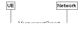
Figure 5.5.5.1-1: Measurement reporting
The purpose of this procedure is to
transfer measurement results from the UE to the network. The UE shall initiate
this procedure only after successful AS security activation.
The UE shall, for each entry in the VarMeasReportList:
1> if the eventH1 or eventH2 is
configured in the corresponding reportConfig associated with the measId
that triggered the measurement reporting:
2> for all the entries in the VarMeasReportList
for which the measurement reporting procedure was triggered and the
corresponding reportConfig is configured with the same eventID
and simulMultiTriggerSingleMeasReport set to true:
3> except for the entry corresponding to the
event for which the difference between the configured altitude threshold and
the altitude of the UE is the smallest, remove all other measurement reporting
entries from the VarMeasReportList, if any, and stop the associated
periodical reporting timer(s), if running;
1> else if the eventA3H1 or eventA3H2
or eventA4H1 or eventA4H2 or eventA5H1 or eventA5H2
is configured in the corresponding reportConfig associated with the measId
that triggered the measurement reporting:
2> for all the entries in the VarMeasReportList
associated with the same measObjectNR for which the measurement
reporting procedure was triggered and the corresponding reportConfig is
configured with the same eventID and simulMultiTriggerSingleMeasReport
set to true:
3> except for the entry corresponding to the
event for which the difference between the configured altitude threshold and
the altitude of the UE is the smallest, remove all other measurement reporting
entries from the VarMeasReportList, if any, and stop the associated
periodical reporting timer(s), if running;
For the measId for which the
measurement reporting procedure was triggered, the UE shall set the measResults
within the MeasurementReport message as follows:
1> set the measId to the measurement
identity that triggered the measurement reporting;
1> for each serving cell configured with servingCellMO:
2> if the reportConfig associated with the measId that triggered the measurement
reporting includes rsType:
3> if the serving cell measurements based on
the rsType included in the reportConfig that triggered the measurement report are
available:
4> set the measResultServingCell within measResultServingMOList
to include RSRP, RSRQ and the available SINR of the serving cell, derived based
on the rsType included in the reportConfig that triggered the
measurement report;
2> else:
3> if SSB based serving
cell measurements are available:
4> set the measResultServingCell
within measResultServingMOList to include RSRP, RSRQ and the available
SINR of the serving cell, derived based on SSB;
3> else if CSI-RS based serving cell
measurements are available:
4> set the measResultServingCell
within measResultServingMOList to include RSRP, RSRQ and the available
SINR of the serving cell, derived based on CSI-RS;
1> set the servCellId within measResultServingMOList
to include each NR serving cell that is configured with servingCellMO,
if any;
1> if the reportConfig associated with
the measId that triggered the measurement reporting includes reportQuantityRS-Indexes
and maxNrofRS-IndexesToReport:
2> for each serving cell configured with servingCellMO,
include beam measurement information according to the associated reportConfig
as described in 5.5.5.2;
1> if the reportConfig associated with
the measId that triggered the measurement reporting includes reportAddNeighMeas:
2> for each measObjectId referenced in
the measIdList which is also referenced with servingCellMO, other
than the measObjectId corresponding with the measId that
triggered the measurement reporting:
3> if the measObjectNR indicated by the servingCellMO
includes the RS resource configuration corresponding to the rsType
indicated in the reportConfig:
4> set the measResultBestNeighCell
within measResultServingMOList to include the physCellId and the
available measurement quantities based on the reportQuantityCell and rsType indicated in reportConfig
of the non-serving cell corresponding to the concerned measObjectNR with
the highest measured RSRP if RSRP measurement results are available for cells
corresponding to this measObjectNR, otherwise with the highest measured
RSRQ if RSRQ measurement results are available for cells corresponding to this measObjectNR,
otherwise with the highest measured SINR;
4> if the reportConfig associated with
the measId that triggered the measurement reporting includes reportQuantityRS-Indexes
and maxNrofRS-IndexesToReport:
5> for each best non-serving cell included in
the measurement report:
6> include beam measurement information
according to the associated reportConfig as described in 5.5.5.2;
1> if the reportConfig associated with
the measId that triggered the measurement reporting is set to eventTriggered
and eventID is set to eventA3, or eventA4, or eventA5,
or eventB1, or eventB2, or eventA3H1, or eventA3H2, or
eventA4H1, or eventA4H2, or eventA5H1, or eventA5H2:
2> if the UE is in NE-DC and the measurement
configuration that triggered this measurement report is associated with the
MCG:
3> set the measResultServFreqListEUTRA-SCG
to include an entry for each E-UTRA SCG serving frequency with the following:
4> include carrierFreq of the E-UTRA
serving frequency;
4> set the measResultServingCell to
include the available measurement quantities that the UE is configured to
measure by the measurement configuration associated with the SCG;
4> if reportConfig associated with the measId
that triggered the measurement reporting includes reportAddNeighMeas:
5> set the measResultServFreqListEUTRA-SCG
to include within measResultBestNeighCell the quantities of the best
non-serving cell, based on RSRP, on the concerned serving frequency;
1> if reportConfig associated with the measId
that triggered the measurement reporting is set to eventTriggered and eventID
is set to eventA3, or eventA4, or eventA5, or eventA3H1,
or eventA3H2, or eventA4H1, or eventA4H2, or eventA5H1,
or eventA5H2:
2> if the UE is in NR-DC and the measurement
configuration that triggered this measurement report is associated with the
MCG:
3> set the measResultServFreqListNR-SCG
to include for each NR SCG serving cell that is configured with servingCellMO,
if any, the following:
4> if the reportConfig associated with
the measId that triggered the measurement reporting includes rsType:
5> if the serving cell measurements based on
the rsType included in the reportConfig that triggered the
measurement report are available according to the measurement configuration
associated with the SCG:
6> set the measResultServingCell within measResultServFreqListNR-SCG
to include RSRP, RSRQ and the available SINR of the serving cell, derived based
on the rsType included in the reportConfig that triggered the
measurement report;
4> else:
5> if SSB based serving cell measurements are
available according to the measurement configuration associated with the SCG:
6> set the measResultServingCell within measResultServFreqListNR-SCG
to include RSRP, RSRQ and the available SINR of the serving cell, derived based
on SSB;
5> else if CSI-RS based serving cell
measurements are available according to the measurement configuration
associated with the SCG:
6> set the measResultServingCell within measResultServFreqListNR-SCG
to include RSRP, RSRQ and the available SINR of the serving cell, derived based
on CSI-RS;
4> if results for the serving cell derived
based on SSB are included:
5> include the ssbFrequency to the value
indicated by ssbFrequency as included in the MeasObjectNR of the serving
cell;
4> if results for the serving cell derived
based on CSI-RS are included:
5> include the refFreqCSI-RS to the
value indicated by refFreqCSI-RS as included in the MeasObjectNR
of the serving cell;
4> if the reportConfig associated with
the measId that triggered the measurement reporting includes reportQuantityRS-Indexes
and maxNrofRS-IndexesToReport:
5> for each serving cell configured with servingCellMO,
include beam measurement information according to the associated reportConfig
as described in 5.5.5.2, where availability is
considered according to the measurement configuration
associated with the SCG;
4> if reportConfig associated with the measId
that triggered the measurement reporting includes reportAddNeighMeas:
5> if the measObjectNR indicated by the servingCellMO
includes the RS resource configuration corresponding to the rsType
indicated in the reportConfig:
6> set the measResultNeighCellListNR
within measResultServFreqListNR-SCG to include one entry with the physCellId
and the available measurement quantities based on the reportQuantityCell and rsType indicated in reportConfig of the
non-serving cell corresponding to the concerned measObjectNR with the
highest measured RSRP if RSRP measurement results are available for cells
corresponding to this measObjectNR, otherwise with the highest measured
RSRQ if RSRQ measurement results are available for cells corresponding to this measObjectNR,
otherwise with the highest measured SINR, where
availability is considered according to the measurement
configuration associated with the SCG;
7> if the reportConfig associated with
the measId that triggered the measurement reporting includes reportQuantityRS-Indexes
and maxNrofRS-IndexesToReport:
8> for each best non-serving cell included in
the measurement report:
9> include beam measurement information
according to the associated reportConfig as described in 5.5.5.2, where availability is considered according
to the measurement configuration associated with the SCG;
1> if the measRSSI-ReportConfig is
configured within the corresponding reportConfig for this measId:
2> set the rssi-Result to the linear average
of sample value(s) provided by lower layers in the reportInterval;
2> set the channelOccupancy to the
rounded percentage of sample values which are beyond the channelOccupancyThreshold
within all the sample values in the reportInterval;
1> if the UE is acting
as L2 U2N Remote UE:
2> set the sl-MeasResultServingRelay
in accordance with the following:
3> set the cellIdentity
to include the cellAccessRelatedInfo contained in the discovery message
received from the serving L2 U2N Relay UE;
3> set the sl-RelayUE-Identity
to include the Source L2 ID of the serving L2 U2N Relay;
3> if the measurement
of serving L2 U2N Relay UE is based on SL-RSRP:
4> set the sl-MeasResult
to include the SL-RSRP of the serving L2 U2N Relay UE;
4> set the sl-MeasQuantity to sl-rsrp,
if supported by the UE;
3> else:
4> set the sl-MeasResult
to include the SD-RSRP of the serving L2 U2N Relay UE;
4> set the sl-MeasQuantity
to sd-rsrp, if supported by the UE;
NOTE 1: In case of no data transmission from L2
U2N Relay UE to L2 U2N Remote UE, it is left to UE implementation whether to
use SL-RSRP or SD-RSRP when setting the sl-MeasResultServingRelay of the
serving L2 U2N Relay UE.
1> if there is at least one applicable
neighbouring cell or candidate L2 U2N Relay UE to report:
2> if the reportType is set to eventTriggered
or periodical:
3> if the measurement report concerns the
candidate L2 U2N Relay UE:
4> set the sl-MeasResultsCandRelay in measResultNeighCells
to include the best candidate L2 U2N Relay UEs up to maxNrofRelayMeas in
accordance with the following:
5> if the reportType is set to eventTriggered:
6> include the L2 U2N Relay UEs included in the
relaysTriggeredList as defined within the VarMeasReportList for
this measId;
5> else:
6> include the applicable L2 U2N Relay UEs for
which the new measurement results became available since the last periodical
reporting or since the measurement was initiated or reset;
5> for each L2 U2N Relay UE that is included in
the sl-MeasResultsCandRelay:
6> set the cellIdentity to include the cellAccessRelatedInfo
contained in the discovery message received from the concerned L2 U2N Relay UE;
6> set the sl-RelayUE-Identity to
include the Source L2 ID of the concerned L2 U2N Relay UE;
6> set the sl-MeasResult to include the
SD-RSRP of the concerned L2 U2N Relay UE;
5> for each included L2 U2N Relay UE, include
the layer 3 filtered measured results in accordance with the reportConfig
for this measId, ordered as follows:
6> set the sl-MeasResult to include the
quantity(ies) indicated in the reportQuantityRelay within the concerned reportConfigRelay in decreasing order of the sorting quantity, determined as specified in 5.5.5.3,
i.e. the best L2 U2N Relay UE is included first;
6> if the UE supports multipathRemoteUE-PC5L2 and
idle/inactive relay UE reporting, and if the sl-RelayIndication is contained in the discovery message received from the concerned
L2 U2N Relay UE:
7> set the sl-RelayIndicationMP in the sl-MeasResultsCandRelay;
3> else:
4> set the measResultNeighCells to
include the best neighbouring cells up to maxReportCells in accordance
with the following:
5> if the reportType is set to eventTriggered
and eventId is not set to eventD1 or eventD2 or eventH1 or eventH2:
6> include the cells included in the cellsTriggeredList
as defined within the VarMeasReportList for this measId;
5> else:
6> include the applicable cells for which the
new measurement results became available since the last periodical reporting or
since the measurement was initiated or reset;
5> for each cell that is included in the measResultNeighCells,
include the physCellId;
5> if the reportType is set to eventTriggered
or periodical:
6> for each included cell, include the layer 3
filtered measured results in accordance with the reportConfig for this measId,
ordered as follows:
7> if the measObject associated with
this measId concerns NR:
8> if rsType in the associated reportConfig
is set to ssb:
9> set resultsSSB-Cell within the measResult
to include the SS/PBCH block based quantity(ies) indicated in the reportQuantityCell
within the concerned reportConfig, in decreasing order of the sorting
quantity, determined as specified in 5.5.5.3, i.e. the best cell is included
first;
9> if reportQuantityRS-Indexes and maxNrofRS-IndexesToReport are configured,
include beam measurement information as described in 5.5.5.2;
8> else if rsType in the associated reportConfig
is set to csi-rs:
9> set resultsCSI-RS-Cell within the measResult
to include the CSI-RS based quantity(ies) indicated in the reportQuantityCell
within the concerned reportConfig, in decreasing order of the sorting quantity,
determined as specified in 5.5.5.3, i.e. the best cell is included first;
9> if reportQuantityRS-Indexes and maxNrofRS-IndexesToReport are configured, include beam measurement information as described in 5.5.5.2;
7> if the measObject associated with
this measId concerns E-UTRA:
8> set the measResult to include the
quantity(ies) indicated in the reportQuantity within the concerned reportConfigInterRAT in decreasing order of the sorting quantity, determined as specified in 5.5.5.3,
i.e. the best cell is included first;
7> if the measObject associated with
this measId concerns UTRA-FDD and if ReportConfigInterRAT
includes the reportQuantityUTRA-FDD:
8> set the measResult to include the
quantity(ies) indicated in the reportQuantityUTRA-FDD within the concerned reportConfigInterRAT in decreasing order of the sorting quantity,
determined as specified in 5.5.5.3, i.e. the best cell
is included first;
6> if reportType is set to eventTriggered
and reportOnBestCellChange is configured:
7> if reportOnBestCellChange is set to n1:
8> set the reportedBestNeighbourCell
defined within the VarMeasReportList for this measId to the first
cell listed in the measResultNeighCells;
7> if reportOnBestCellChange is set to n2:
8> set the first cell in reportedBestNeighbourCell
defined within the VarMeasReportList for this measId to the first
cell listed in the measResultNeighCells and the second cell in reportedBestNeighbourCell
defined within the VarMeasReportList for this measId to the
second cell listed in the measResultNeighCells, if available;
2> else:
3> if the cell indicated by cellForWhichToReportCGI
is an NR cell:
4> if plmn-IdentityInfoList of the cgi-Info
for the concerned cell has been obtained:
5> include the plmn-IdentityInfoList
including plmn-IdentityList, trackingAreaCode (if available), trackingAreaList (if available), ranac (if available), cellIdentity
and cellReservedForOperatorUse for each entry of the plmn-IdentityInfoList;
5> include frequencyBandList if
available;
5> for each PLMN-IdentityInfo in plmn-IdentityInfoList:
6> if the gNB-ID-Length is broadcast:
7> include gNB-ID-Length;
4> if nr-CGI-Reporting-NPN is supported
by the UE and npn-IdentityInfoList of the cgi-Info for the
concerned cell has been obtained:
5> include the npn-IdentityInfoList including npn-IdentityList, trackingAreaCode, ranac (if
available), cellIdentity
and cellReservedForOperatorUse for each entry of the npn-IdentityInfoList;
5> for each NPN-IdentityInfo in NPN-IdentityInfoList:
6> if the gNB-ID-Length is broadcast:
7> include gNB-ID-Length;
5> include cellReservedForOtherUse if available;
4> else if MIB indicates the SIB1
is not broadcast:
5> include the noSIB1 including the ssb-SubcarrierOffset
and pdcch-ConfigSIB1 obtained from MIB of the concerned cell;
3> if the cell indicated by cellForWhichToReportCGI
is an E-UTRA cell:
4> if all mandatory fields of the cgi-Info-EPC
for the concerned cell have been obtained:
5> include in the cgi-Info-EPC the
fields broadcasted in E-UTRA SystemInformationBlockType1 associated to
EPC;
4> if the UE is E-UTRA/5GC capable and all
mandatory fields of the cgi-Info-5GC for the concerned cell have been
obtained:
5> include in the cgi-Info-5GC the
fields broadcasted in E-UTRA SystemInformationBlockType1 associated to
5GC;
4> if the mandatory present fields of the cgi-Info
for the cell indicated by the cellForWhichToReportCGI in the associated measObject
have been obtained:
5> include the freqBandIndicator;
5> if the cell broadcasts the multiBandInfoList,
include the multiBandInfoList;
5> if the cell broadcasts the freqBandIndicatorPriority,
include the freqBandIndicatorPriority;
1> if reportConfig associated with the measId
that triggered the measurement reporting is set to eventTriggered and if
enteringLeavingReport is configured:
2> for each cell that is included in measResultNeighCells:
3> if the measObject associated with
this measId concerns NR:
4> if event entry condition for the event that
triggered this measurement report has been fulfilled for the cell and the cell
has just been included to cellsTriggeredList:
5> set entering to true for the
concerned NR cell;
2> if the field cellsMetLeavingCond
within the VarMeasReportList for this measId is not empty:
3> set cellsMetReportOnLeaveList to include the
cell(s) in cellsMetLeavingCond;
1> if the corresponding measObject
concerns NR:
2> if the reportSFTD-Meas
is set to true within the corresponding reportConfigNR for this measId:
3> set the measResultSFTD-NR in
accordance with the following:
4> set sfn-OffsetResult and frameBoundaryOffsetResult
to the measurement results provided by lower layers;
4> if the reportRSRP is set to true;
5> set rsrp-Result to the RSRP of the NR
PSCell derived based on SSB;
2> else if the reportSFTD-NeighMeas
is included within the
corresponding reportConfigNR for this measId:
3> for each applicable cell which measurement
results are available, include an entry in the measResultCellListSFTD-NR and
set the contents as follows:
4> set physCellId to the physical cell
identity of the concerned NR neighbour cell.
4> set sfn-OffsetResult and frameBoundaryOffsetResult
to the measurement results provided by lower layers;
4> if the reportRSRP is set to true:
5> set rsrp-Result to the RSRP of the
concerned cell derived based on SSB;
1> else if the corresponding measObject
concerns E-UTRA:
2> if the reportSFTD-Meas
is set to true within the corresponding reportConfigInterRAT for
this measId:
3> set the measResultSFTD-EUTRA in
accordance with the following:
4> set sfn-OffsetResult and frameBoundaryOffsetResult
to the measurement results provided by lower layers;
4> if the reportRSRP is set to true;
5> set rsrpResult-EUTRA to the RSRP of
the EUTRA PSCell;
1> if average uplink PDCP delay values are
available:
2> set the ul-PDCP-DelayValueResultList
to include the corresponding average uplink PDCP delay values;
1> if PDCP excess delay measurements are
available:
2> set the ul-PDCP-ExcessDelayResultList
to include the corresponding PDCP excess delay measurements;
1> if the includeCommonLocationInfo is
configured in the corresponding reportConfig for this measId and
detailed location information that has not been reported is available, set the
content of commonLocationInfo of the locationInfo as follows:
2> include the locationTimestamp;
2> include the locationCoordinate, if
available;
2> include the velocityEstimate, if
available;
2> include the locationError, if
available;
2> include the locationSource, if
available;
2> if available, include the gnss-TOD-msec,
1> if the coarseLocationRequest is set
to true in the corresponding reportConfig for this measId:
2> include coarseLocationInfo, if
available;
1> if the includeWLAN-Meas is configured
in the corresponding reportConfig for this measId, set the wlan-LocationInfo
of the locationInfo in the measResults as follows:
2> if available, include the LogMeasResultWLAN,
in order of decreasing RSSI for WLAN APs;
1> if the includeBT-Meas is configured
in the corresponding reportConfig for this measId, set the BT-LocationInfo
of the locationInfo in the measResults as follows:
2> if available, include the LogMeasResultBT,
in order of decreasing RSSI for Bluetooth beacons;
1> if the includeSensor-Meas is
configured in the corresponding reportConfig for this measId, set
the sensor-LocationInfo of the locationInfo in the measResults
as follows:
2> if available, include the sensor-MeasurementInformation;
2> if available, include the sensor-MotionInformation;
1> if the includeAltitudeUE is set to true
in the corresponding reportConfig for this measId:
2> set the altitudeUE to include the
altitude of the UE;
1> if there is at least one applicable
transmission resource pool for NR sidelink communication/discovery (for measResultsSL):
2> set the measResultsListSL to include the CBR measurement results in accordance with the following:
3> if the reportType is set to eventTriggered:
4> include the transmission resource pools
included in the poolsTriggeredList as defined within the VarMeasReportList
for this measId;
3> else:
4> include the applicable transmission resource pools for which the new measurement results became available since the
last periodical reporting or since the measurement was initiated or reset;
3> if the corresponding measObject
concerns NR sidelink communication/discovery, then for
each transmission resource pool
to be reported:
4> set the sl-poolReportIdentity to the
identity of this transmission resource pool;
4> set the sl-CBR-ResultsNR to the CBR
measurement results on PSSCH and PSCCH of this transmission resource pool
provided by lower layers, if available;
NOTE 1: Void.
1> if there is at least one applicable CLI
measurement resource to report:
2> if the reportType is set to cli-EventTriggered
or cli-Periodical:
3> set the measResultCLI to include the
most interfering SRS resources or most interfering CLI-RSSI resources up to maxReportCLI
in accordance with the following:
4> if the reportType is set to cli-EventTriggered:
5> if trigger quantity is set to srs-RSRP
i.e. i1-Threshold is set to srs-RSRP:
6> include the SRS resource included in the cli-TriggeredList
as defined within the VarMeasReportList for this measId;
5> if trigger quantity is set to cli-RSSI
i.e. i1-Threshold is set to cli-RSSI:
6> include the CLI-RSSI resource included in
the cli-TriggeredList as defined within the VarMeasReportList for
this measId;
4> else:
5> if reportQuantityCLI is set to srs-rsrp:
6> include the applicable SRS resources for
which the new measurement results became available since the last periodical
reporting or since the measurement was initiated or reset;
5> else:
6> include the applicable CLI-RSSI resources
for which the new measurement results became available since the last
periodical reporting or since the measurement was initiated or reset;
4> for each SRS resource that is included in
the measResultCLI:
5> include the srs-ResourceId;
5> set srs-RSRP-Result to include the
layer 3 filtered measured results in decreasing order, i.e. the most
interfering SRS resource is included first;
4> for each CLI-RSSI resource that is included
in the measResultCLI:
5> include the rssi-ResourceId;
5> set cli-RSSI-Result to include the
layer 3 filtered measured results in decreasing order, i.e. the most
interfering CLI-RSSI resource is included first;
1> if there is at least one applicable UE Rx-Tx
time difference measurement to report:
2> set measResultRxTxTimeDiff to the
latest measurement result;
1> increment the numberOfReportsSent as
defined within the VarMeasReportList for this measId by 1;
1> stop the periodical reporting timer, if
running;
1> if the numberOfReportsSent as defined
within the VarMeasReportList for this measId is less than the reportAmount
as defined within the corresponding reportConfig for this measId:
2> start the periodical reporting timer with
the value of reportInterval as defined within the corresponding reportConfig
for this measId;
1> else:
2> if the reportType is set to periodical
or cli-Periodical or rxTxPeriodical:
3> remove the entry within the VarMeasReportList
for this measId;
3> remove this measId from the measIdList
within VarMeasConfig;
1> if the measurement reporting was configured
by a sl-ConfigDedicatedNR received within the RRCConnectionReconfiguration:
2> submit the MeasurementReport message
to lower layers for transmission via SRB1, embedded in E-UTRA RRC message ULInformationTransferIRAT
as specified TS 36.331 [10], clause 5.6.28;
1> else if the UE is in (NG)EN-DC:
2> if SRB3 is configured and the SCG is not
deactivated:
3> submit the MeasurementReport message
via SRB3 to lower layers for transmission, upon which the procedure ends;
2> else:
3> submit the MeasurementReport message
via E-UTRA embedded in E-UTRA RRC message ULInformationTransferMRDC as
specified in TS 36.331 [10].
1> else if the UE is in NR-DC:
2> if the measurement configuration that
triggered this measurement report is associated with the SCG:
3> if SRB3 is configured and the SCG is not
deactivated:
4> submit the MeasurementReport message
via SRB3 to lower layers for transmission, upon which the procedure ends;
3> else:
4> submit the MeasurementReport message
via SRB1 embedded in NR RRC message ULInformationTransferMRDC as
specified in 5.7.2a.3;
2> else:
3> submit the MeasurementReport message
via SRB1 to lower layers for transmission, upon which the procedure ends;
1> else:
2> submit the MeasurementReport message
to lower layers for transmission, upon which the procedure ends.
For beam measurement information to be
included in a measurement report the UE shall:
1> if reportType is set to eventTriggered
or reportOnScellActivation:
2> consider the trigger quantity as the sorting
quantity if available, otherwise RSRP as sorting quantity if available,
otherwise RSRQ as sorting quantity if available, otherwise SINR as sorting
quantity;
1> if reportType is set to periodical:
2> if a single reporting quantity is set to true in reportQuantityRS-Indexes;
3> consider the configured single quantity as
the sorting quantity;
2> else:
3> if rsrp is set to true;
4> consider RSRP as the sorting quantity;
3> else:
4> consider RSRQ as the sorting quantity;
1> set rsIndexResults to include up to maxNrofRS-IndexesToReport
SS/PBCH block indexes or CSI-RS indexes in order of decreasing sorting quantity
as follows:
2> if the measurement information to be
included is based on SS/PBCH block:
3> include within resultsSSB-Indexes the
index associated to the best beam for that SS/PBCH block sorting quantity and
if absThreshSS-BlocksConsolidation is included in the VarMeasConfig
for the measObject associated to the cell for which beams are to be
reported, the remaining beams whose sorting quantity is above absThreshSS-BlocksConsolidation;
3> if includeBeamMeasurements is set to true,
include the SS/PBCH based measurement results for the quantities in reportQuantityRS-Indexes
for each SS/PBCH block index;
2> else if the beam measurement information to
be included is based on CSI-RS:
3> include within resultsCSI-RS-Indexes
the index associated to the best beam for that CSI-RS sorting quantity and, if absThreshCSI-RS-Consolidation
is included in the VarMeasConfig for the measObject
associated to the cell for which beams are to be reported, the remaining beams
whose sorting quantity is above absThreshCSI-RS-Consolidation;
3> if includeBeamMeasurements is set to true,
include the CSI-RS based measurement results for the quantities in reportQuantityRS-Indexes
for each CSI-RS index.
The UE shall determine the sorting quantity
according to parameters of the reportConfig associated with the measId
that triggered the reporting:
1> if the reportType is set to eventTriggered:
2> for an NR cell, consider the quantity used
in the aN-Threshold (for eventA1, eventA2, eventA4,
eventA4H1 and eventA4H2) or in the a5-Threshold2 (for eventA5,
eventA5H1 and eventA5H2) or in the aN-Offset (for eventA3,
eventA3H1, eventA3H2 and eventA6) or in the x1-Threshold2 (for eventX1) as the sorting quantity;
2> for an E-UTRA cell, consider the quantity
used in the bN-ThresholdEUTRA as the sorting quantity;
2> for an UTRA-FDD cell, consider the quantity
used in the bN-ThresholdUTRA-FDD as the sorting quantity;
2> for a candidate L2 U2N Relay UE, consider
the y1-Threshold2-Relay
(for eventY1-Relay) or
y2-Threshold-Relay (for eventY2-Relay) or z1-Threshold2-Relay (for
eventZ1) as the sorting quantity;
1> if the reportType is set to periodical:
2> determine the sorting quantity according to reportQuantityCell
for an NR cell, and according to reportQuantity for an E-UTRA cell, as
below:
3> if a single quantity is set to true:
4> consider this quantity as the sorting
quantity;
3> else:
4> if rsrp is set to true;
5> consider RSRP as the sorting quantity;
4> else:
5> consider RSRQ as the sorting quantity;
2> determine the sorting quantity according to reportQuantityUTRA-FDD
for UTRA-FDD cell, as below:
3> if a single quantity is set to true:
4> consider this quantity as the sorting
quantity;
3> else:
4> consider RSCP as the sorting quantity.
2> for a candidate L2 U2N Relay UE, consider
the reportQuantityRelay as the sorting quantity;
Figure 5.5.6.1-1: Location measurement indication
The purpose of this procedure is to
indicate to the network that the UE is going to start/stop location related
measurements towards E-UTRA or NR which require measurement gaps or start/stop
detection of subframe and slot timing towards E-UTRA (eutra-FineTimingDetection)
which requires measurement gaps. UE shall initiate this procedure only
after successful AS security activation.
NOTE: It is a network decision to configure
the measurement gap.
The UE shall:
1> if and only if upper layers indicate to
start performing location measurements towards E-UTRA or NR or start subframe
and slot timing detection towards E-UTRA, and the UE requires measurement gaps
for these operations while measurement gaps are either not configured or not
sufficient:
2> if preconfigured measurement gaps for
positioning and posMG-Request are configured and the UE considers that at least one of the
preconfigured measurement gaps for positioning is sufficient for the location
measurement when activated:
3> trigger the lower layers to initiate the
measurement gap activation request using UL MAC CE as specified in TS 38.321 [3];
2> else:
3> initiate the procedure to indicate start as
specified in clause 5.5.6.3;
NOTE 1: The UE verifies the measurement gap
situation only upon receiving the indication from upper layers. If at this
point in time sufficient gaps are available, the UE does not initiate the
procedure. Unless it receives a new indication from upper layers, the UE is
only allowed to further repeat the procedure in the same PCell once per
frequency of the target RAT if the provided measurement gaps are insufficient.
NOTE 1a: When indication is received from upper
layers for performing location measurement and there is pre-configured
measurement gap configured (not preconfigured measurement gap for positioning),
the UE considers this preconfigured measurement gap to be not sufficient if the
measurement gap is not considered to be always activated according to clause
9.1.7.2 of TS 38.133 [14].
1> if and only if upper layers indicate to stop
performing location measurements towards E-UTRA or NR or stop subframe and slot
timing detection towards E-UTRA:
2> if there is no activated preconfigured
measurement gap for positioning:
3> if there is previously triggered UL MAC CE
transmission for the measurement gap activation for positioning:
4> indicate to the lower layers to cancel the
triggered UL MAC CE transmission for the measurement gap activation as
specified in TS 38.321 [3];
2> else if there is activated preconfigured
measurement gap for positioning:
3> trigger the lower layers to deactivate all
the activated measurement gap(s) for positioning as specified in TS 38.321 [3].
2> if there is configured measurement gap used
for positioning and the measurement gap is not the activated preconfigured
measurement gap for positioning:
3> initiate the procedure to indicate stop as
specified in 5.5.6.3.
NOTE 2: The UE may initiate the procedure to
indicate stop even if it did not previously initiate the procedure to indicate
start.
The UE shall set the contents of LocationMeasurementIndication
message as follows:
1> if the procedure is initiated to indicate
start of location related measurements:
2> if the procedure is initiated for RSTD
measurements towards E-UTRA:
3> set the measurementIndication to the eutra-RSTD
according to the information received from upper layers;
2> else if the procedure is initiated for
positioning measurement towards NR:
3> set the measurementIndication to the nr-PRS-Measurement
according to the information received from upper layers;
1> else if the procedure is initiated to
indicate stop of location related measurements:
2> set the measurementIndication to the
value release;
1> if the procedure is initiated to indicate
start of subframe and slot timing detection towards E-UTRA:
2> set the measurementIndication to the
value eutra-FineTimingDetection;
1> else if the procedure is initiated to
indicate stop of subframe and slot timing detection towards E-UTRA:
2> set the measurementIndication to the
value release;
1> submit the LocationMeasurementIndication
message to lower layers for transmission, upon which the procedure ends.
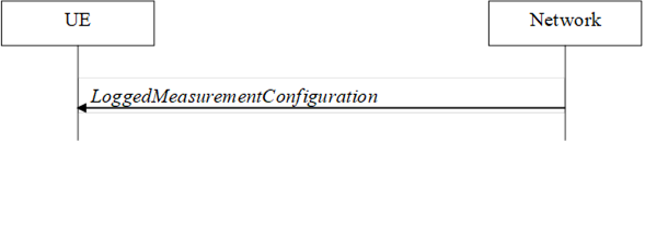
Figure 5.5a.1.1-1: Logged measurement
configuration
The purpose of this procedure is to configure
the UE to perform logging of measurement results while in RRC_IDLE and
RRC_INACTIVE. The procedure applies to logged measurements capable UEs that are
in RRC_CONNECTED.
NOTE: NG-RAN may retrieve stored logged
measurement information by means of the UE information procedure.
NG-RAN initiates the logged measurement
configuration procedure to UE in RRC_CONNECTED by sending the LoggedMeasurementConfiguration
message.
Upon receiving the LoggedMeasurementConfiguration
message the UE shall:
1> discard the logged measurement configuration
as well as the logged measurement information as specified in 5.5a.2;
1> store the received loggingDuration, reportType
and areaConfiguration, if included, in VarLogMeasConfig;
1> If the UE is in SNPN access mode:
2> if the LoggedMeasurementConfiguration
message includes snpn-ConfigList:
3> set the snpn-ConfigID-List in VarLogMeasReport
to include the current registered SNPN identity as well as SNPN identities in snpn-Config-List;
2> else:
3> set the snpn-ConfigID-List
in VarLogMeasReport to include the current registered SNPN identity;
1> else if the LoggedMeasurementConfiguration
message includes plmn-IdentityList:
2> set plmn-IdentityList in VarLogMeasReport
to include the RPLMN as well as the PLMNs included in plmn-IdentityList;
1> else:
2> set plmn-IdentityList in VarLogMeasReport
to include the RPLMN;
1> store the received absoluteTimeInfo, traceReference, traceRecordingSessionRef, and tce-Id in VarLogMeasReport;
1> store the received bt-NameList, if
included, in VarLogMeasConfig;
1> store the received wlan-NameList, if
included, in VarLogMeasConfig;
1> store the received sensor-NameList,
if included, in VarLogMeasConfig;
1> start timer T330 with the timer value set to
the loggingDuration;
1> store the received sigLoggedMeasType, if included, in VarLogMeasReport;
1> store the received earlyMeasIndication, if included, in VarLogMeasConfig;
Upon expiry of T330 the UE shall:
1> release VarLogMeasConfig;
The UE is allowed to discard stored logged
measurements, i.e. to release VarLogMeasReport, 48 hours after T330
expiry.
The purpose of this procedure is to release
the logged measurement configuration as well as the logged measurement
information.
The UE shall initiate the procedure upon
receiving a logged measurement configuration in same or another RAT. The UE
shall also initiate the procedure upon power off or upon
deregistration.
The UE shall:
1> stop timer T330, if running;
1> if stored, discard the logged measurement
configuration as well as the logged measurement information, i.e. release the
UE variables VarLogMeasConfig and VarLogMeasReport.
This procedure specifies the logging of
available measurements by a UE in RRC_IDLE and RRC_INACTIVE that has a logged
measurement configuration. The actual process of logging within the UE, takes
place in RRC_IDLE state could continue in RRC_INACTIVE state or vice versa.
While T330 is running and SDT procedure is
not ongoing, the UE shall:
1> if measurement logging is suspended:
2> if during
the last logging interval the IDC problems detected by the UE is resolved,
resume measurement logging;
1> if not suspended, perform the logging in
accordance with the following:
2> if the reportType is set to periodical
in the VarLogMeasConfig:
3> if the UE is in any cell selection state (as
specified in TS 38.304 [20]):
4> perform the logging
at regular time intervals, as defined by the loggingInterval in the VarLogMeasConfig;
3> if the UE is in camped
normally state on an NR cell and if the RPLMN is included in plmn-IdentityList
stored in VarLogMeasReport; or
3> if the UE is in
camped normally state on an NR cell and if the registered SNPN identity is
included in snpn-ConfigID-List stored in VarLogMeasReport:
4> if areaConfiguration
is not included in VarLogMeasConfig; or
4> if the serving cell
is part of the area indicated by areaConfig in areaConfiguration
in VarLogMeasConfig; or
4> if the serving cell is part of the area
indicated by cag-ConfigList in areaConfiguration in VarLogMeasConfig;
or
4> if the serving cell is part of the area
indicated by snpn-ConfigList in areaConfiguration in VarLogMeasConfig:
5> perform the logging
at regular time intervals, as defined by the loggingInterval in the VarLogMeasConfig;
2> else if the reportType is set to eventTriggered, and eventType is set to outOfCoverage:
3> perform the logging at regular time
intervals as defined by the loggingInterval in VarLogMeasConfig only when the UE is in any cell selection state;
3> upon transition from any cell selection
state to camped normally state in NR:
4> if the RPLMN is included in plmn-IdentityList
stored in VarLogMeasReport, or if the registered
SNPN identity is included in snpn-ConfigID-List stored in VarLogMeasReport; and
4> if areaConfiguration is not included in VarLogMeasConfig
or if the current camping cell is part of the area indicated by areaConfig of areaConfiguration
in VarLogMeasConfig, or if the current camping
cell is part of the area indicated by cag-ConfigList of areaConfiguration
in VarLogMeasConfig, or if the current camping cell is part of the area
indicated by snpn-ConfigList of areaConfiguration in VarLogMeasConfig:
5> perform the logging;
2> else if the reportType is set to eventTriggered
and eventType is set to eventL1:
3> if the UE is in camped
normally state on an NR cell and if the RPLMN is included in plmn-IdentityList
stored in VarLogMeasReport; or
3> if the UE is in
camped normally state on an NR cell and if the registered SNPN identity is
included in snpn-ConfigID-List stored in VarLogMeasReport:
4> if areaConfiguration
is not included in VarLogMeasConfig; or
4> if the serving cell
is part of the area indicated by areaConfig in areaConfiguration
in VarLogMeasConfig; or
4> if the current
serving cell is part of the area indicated by cag-ConfigList of areaConfiguration
in VarLogMeasConfig, or if the current camping cell is part of the area
indicated by snpn-ConfigList of areaConfiguration in VarLogMeasConfig;
5> perform the logging at
regular time intervals as defined by the loggingInterval in VarLogMeasConfig only when the conditions indicated by the eventL1 are met;
2> when performing the
logging:
3> if InterFreqTargetInfo is configured
and if the UE detected IDC problems on at least one of the frequencies included
in InterFreqTargetInfo or any inter-RAT frequency during the last
logging interval, or
3> if InterFreqTargetInfo is not
configured and if the UE detected IDC problems during the last logging
interval:
4> if measResultServingCell in the VarLogMeasReport
is not empty:
5> include inDeviceCoexDetected;
5> suspend measurement logging from the next
logging interval;
4> else:
5> suspend measurement logging;
NOTE 0: If the UE detected and resolved IDC
problem during the last logging interval, the UE does not suspend measurement
logging from the next logging interval and does not suspend measurement logging
for the last logging interval.
3> set the relativeTimeStamp to indicate
the elapsed time since the moment at which the logged measurement configuration
was received;
3> if location information became available
during the last logging interval, set the content of the locationInfo as
in 5.3.3.7:
3> if the UE is in any cell selection state (as
specified in TS 38.304 [20]):
4> set anyCellSelectionDetected
to indicate the detection of no suitable or no acceptable cell found;
4> if the reportType is set to eventTriggered in the VarLogMeasConfig; and
4> if the RPLMN at the
time of entering the any cell selection state is included in plmn-IdentityList
stored in VarLogMeasReport or if the registered SNPN identity at the
time of entering the any cell selection state is included in snpn-ConfigID-List
stored in VarLogMeasReport; and
4> if areaConfiguration is not included in VarLogMeasConfig
or if the last suitable cell that the UE was camping on is part of the area
indicated by areaConfig
of areaConfiguration in VarLogMeasConfig,
or if last suitable cell that the UE was camping on is part of the area
indicated by cag-ConfigList of areaConfiguration in VarLogMeasConfig,
or if last suitable cell that the UE was camping on is part of the area
indicated by snpn-ConfigList of areaConfiguration in VarLogMeasConfig:
5> set the servCellIdentity
to indicate global cell identity of the last suitable cell that the UE was camping on;
5> set the measResultServingCell
to include the quantities of the last suitable cell the UE was camping on;
4> else if the reportType is set to periodical in the VarLogMeasConfig:
5> set the servCellIdentity
to indicate global cell identity of the last logged cell that the UE was
camping on;
5> set the measResultServingCell
to include the quantities of the last logged cell the UE was camping on;
3> else:
4> set the servCellIdentity to indicate
global cell identity of the cell the UE is camping on;
4> set the measResultServingCell to
include the quantities of the cell the UE is camping on;
3> if available, set the measResultNeighCells,
in order of decreasing ranking-criterion as used for cell re-selection, to
include measurements of neighbouring cell that became available during the last
logging interval and according to the following:
4> include measurement results for at most 6
neighbouring cells on the NR serving frequency and for at most 3 cells per NR
neighbouring frequency and for the NR neighbouring frequencies in accordance
with the following:
5> if interFreqTargetInfo is included in
VarLogMeasConfig:
6> if earlyMeasIndication is included in
VarLogMeasConfig;
7> include measurement results for NR
neighbouring frequencies that are included in both interFreqTargetInfo
and either in measIdleCarrierListNR (within the VarMeasIdleConfig)
or SIB4;
6> else:
7> include measurement results for NR
neighbouring frequencies that are included in both interFreqTargetInfo
and SIB4;
5> else:
6> if earlyMeasIndication is included in
VarLogMeasConfig;
7> include measurement results for NR
neighbouring frequencies that are included in either measIdleCarrierListNR (within
the VarMeasIdleConfig) or SIB4;
6> else:
7> include measurement results for NR
neighbouring frequencies that are included in SIB4;
4> include measurement results for at most 3
neighbours per inter-RAT frequency in accordance with the following:
5> if earlyMeasIndication is included in
VarLogMeasConfig:
6> include measurement results for inter-RAT
neighbouring frequencies that are included in either measIdleCarrierListEUTRA
(within the VarMeasIdleConfig) or SIB5;
5> else:
6> include measurement results for inter-RAT
frequencies that are included in SIB5;
4> for each neighbour cell included, include
the optional fields that are available;
NOTE 1: The UE includes the latest results of the
available measurements as used for cell reselection evaluation in RRC_IDLE or
RRC_INACTIVE, which are performed in accordance with the performance
requirements as specified in TS 38.133 [14].
NOTE 2: For logging the measurements on
frequencies (indicated in measIdleCarrierListNR/ measIdleCarrierListEUTRA)
in the logged measurement, the qualityThreshold in measIdleConfig
should not be applied, and how the UE logs the measurements on the frequencies
is left to the UE implementation.
2> when the memory reserved for the logged
measurement information becomes full, stop timer T330 and perform the same
actions as performed upon expiry of T330, as specified in 5.5a.1.4.
This procedure specifies the UE actions for
a UE in RRC_IDLE and RRC_INACTIVE that has an application layer measurement
configuration with appLayerIdleInactiveConfig configured. The procedure
includes area handling, storing of application layer measurement report
containers and cell re-selection to LTE.
While in RRC_INACTIVE and RRC_IDLE state,
the UE shall:
1> store any previously or subsequently
received application layer measurement report containers associated with the measConfigAppLayerId
for which the successful transmission of the message or at least one segment of
the message has not been confirmed by lower layers;
NOTE: The UE continues storing application
layer measurement report containers for MBS broadcast service in RRC_CONNECTED
as long as stored application layer measurement configurations/reports have not
been retrieved.
1> if the memory reserved for storing
application layer measurement report containers becomes full:
2> if the reports are associated with a
configuration including appLayerMeasPriority:
3> discard reports in priority order where
reports with the lowest priority are discarded first, and among reports with
equal associated priority, discard reports in the order they were received,
where older reports are discarded first;
2> else:
3> discard reports in the order they were
received, where older reports are discarded first;
1> if qoe-AreaScope is configured:
2> if the cell which
the UE selects when the UE transits from RRC_CONNECTED state to RRC_INACTIVE or
RRC_IDLE state is part of the area indicated by qoe-AreaScope:
3> inform upper layers of being inside the
area;
2> if the cell which
the UE selects when the UE transits from RRC_CONNECTED state to RRC_INACTIVE or
RRC_IDLE state is not part of the area indicated by qoe-AreaScope:
3> inform upper layers of being outside the
area.
2> if the UE re-selects
to a new cell which is part of the area indicated by qoe-AreaScope and the previous cell was not part of the area indicated by qoe-AreaScope:
3> inform upper layers of being inside the
area;
2> if the UE re-selects
to a new cell which is not part of the area indicated by qoe-AreaScope and the previous cell
was part of the area indicated by qoe-AreaScope:
3> inform upper layers of being outside the
area.
1> if the UE re-selects to an E-UTRA cell:
2> inform upper layers about the release of all
application layer measurement configurations;
2> release all application layer measurement
configurations including their fields in UE variables VarAppLayerIdleConfig
and VarAppLayerPLMN-ListConfig;
2> discard any application layer measurement
reports which were not yet fully submitted to lower layers for transmission;
2> consider itself not to be configured to send
application layer measurement reports.
This clause describes how the UE compiles
and transfers its UE capability information upon receiving a
UECapabilityEnquiry from the network.
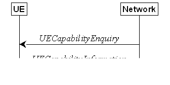
Figure 5.6.1.1-1: UE capability transfer
The network initiates the procedure to a UE
in RRC_CONNECTED when it needs (additional) UE radio access capability
information. The network should retrieve UE capabilities only after AS security
activation. Network does not forward UE capabilities that were retrieved before
AS security activation to the CN.
The UE shall set the contents of UECapabilityInformation
message as follows:
1> if the ue-CapabilityRAT-RequestList
contains a UE-CapabilityRAT-Request with rat-Type set to nr:
2> include in the ue-CapabilityRAT-ContainerList
a UE-CapabilityRAT-Container of the type UE-NR-Capability and
with the rat-Type set to nr;
2> include the supportedBandCombinationList,
featureSets and featureSetCombinations as specified in clause
5.6.1.4;
1> if the ue-CapabilityRAT-RequestList
contains a UE-CapabilityRAT-Request with rat-Type set to eutra-nr:
2> if the UE supports (NG)EN-DC or NE-DC:
3> include in the ue-CapabilityRAT-ContainerList
a UE-CapabilityRAT-Container of the type UE-MRDC-Capability and
with the rat-Type set to eutra-nr;
3> include the supportedBandCombinationList
and featureSetCombinations as specified in clause 5.6.1.4;
1> if the ue-CapabilityRAT-RequestList
contains a UE-CapabilityRAT-Request with rat-Type set to eutra:
2> if the UE supports E-UTRA:
3> include in the ue-CapabilityRAT-ContainerList
a ue-CapabilityRAT-Container of the type UE-EUTRA-Capability associated
with the terrestrial network and with the rat-Type set to eutra
as specified in TS 36.331 [10], clause 5.6.3.3, according to the capabilityRequestFilter,
if received;
1> if the ue-CapabilityRAT-RequestList
contains a UE-CapabilityRAT-Request with rat-Type set to utra-fdd:
2> if the UE supports UTRA-FDD:
3> include the UE radio access capabilities for
UTRA-FDD within a ue-CapabilityRAT-Container and with the rat-Type
set to utra-fdd;
1> if the RRC message segmentation is enabled
based on the field rrc-SegAllowed received, and
the encoded RRC message is larger than the maximum supported size of a PDCP SDU
specified in TS 38.323 [5]:
2> consider the maximum number of UL segments the UE is allowed to use
when segmenting the UECapabilityInformation message is 16;
2> initiate the UL message segment transfer procedure as
specified in clause 5.7.7;
1> else if the RRC message segmentation is enabled based on the field rrc-MaxCapaSegAllowed received,
and the encoded RRC message is larger than the maximum
supported size of a PDCP SDU specified in TS 38.323 [5]:
2> consider the maximum number of UL segments the UE is allowed to use
when segmenting the UECapabilityInformation message to be the value
indicated by rrc-MaxCapaSegAllowed;
2> initiate the UL message segment transfer procedure as
specified in clause 5.7.7;
1> else:
2> submit the UECapabilityInformation
message to lower layers for transmission, upon which the procedure ends.
The UE invokes the procedures in this
clause if the NR or E-UTRA network requests UE capabilities for nr, eutra-nr
or eutra. This procedure is invoked once per requested rat-Type
(see clause 5.6.1.3 for capability enquiry by the NR network; see TS 36.331
[10], clause 5.6.3.3 for capability enquiry by the E-UTRA network). The UE
shall ensure that the feature set IDs are consistent across feature sets,
feature set combinations and band combinations in all three UE capability
containers that the network queries with the same fields with the same values,
i.e. UE-CapabilityRequestFilterNR, UE-CapabilityRequestFilterCommon,
rrc-SegAllowed and fields in UECapabilityEnquiry message (i.e.
requestedFreqBandsNR-MRDC, requestedCapabilityNR, eutra-nr-only flag, requestedCapabilityCommon,
and rrc-SegAllowed) as defined in TS 36.331 [10], where
applicable.
NOTE 1: Capability enquiry without frequencyBandListFilter
is not supported.
NOTE 2: In (NG)EN-DC, the gNB needs the
capabilities for RAT types nr and eutra-nr and it uses the featureSets
in the UE-NR-Capability together with the featureSetCombinations
in the UE-MRDC-Capability to determine the NR UE capabilities for the
supported MRDC band combinations. Similarly, the eNB needs the capabilities for
RAT types eutra and eutra-nr and it uses the featureSetsEUTRA
in the UE-EUTRA-Capability together with the featureSetCombinations
in the UE-MRDC-Capability to determine the E-UTRA UE capabilities for
the supported MRDC band combinations. Hence, the IDs used in the featureSets
must match the IDs referred to in featureSetCombinations across all
three containers. The requirement on consistency implies that there are no
undefined feature sets and feature set combinations.
NOTE 3: If the UE cannot include all feature sets
and feature set combinations due to message size or list size constraints, it
is up to UE implementation which feature sets and feature set combinations it
prioritizes.
NOTE 3a: For the usage of rrc-MaxCapaSegAllowed,
if the NR or E-UTRA network does not request UE capabilities for nr, eutra-nr
and eutra in a single enquiry, the feature set IDs might not be
consistent across feature sets, feature set combinations and band combinations
in all three UE capability containers.
The UE shall:
1> if the UE is an eRedCap UE and the UE
supports
eRedCapIgnoreCapabilityFiltering:
2> ignore the value received in frequencyBandListFilter;
2> in the remainder of this procedure assume frequencyBandListFilter
indicates all the supported bands of the UE;
1> compile a list of "candidate band
combinations" according to the filter criteria in capabilityRequestFilterCommon
(if included), only consisting of bands included in frequencyBandListFilter,
and prioritized in the order of frequencyBandListFilter (i.e. first
include band combinations containing the first-listed band, then include
remaining band combinations containing the second-listed band, and so on),
where for each band in the band combination, the parameters of the band do not
exceed maxBandwidthRequestedDL, maxBandwidthRequestedUL, maxCarriersRequestedDL,
maxCarriersRequestedUL, ca-BandwidthClassDL-EUTRA or ca-BandwidthClassUL-EUTRA,
whichever are received;
1> for each band combination included in the
list of "candidate band combinations":
2> if the network (E-UTRA) included the eutra-nr-only
field, or
2> if the requested rat-Type is eutra:
3> remove the NR-only band combination from the
list of "candidate band combinations";
NOTE 4: The (E-UTRA) network may request
capabilities for nr but indicate with the eutra-nr-only flag that
the UE shall not include any NR band combinations in the UE-NR-Capability.
In this case the procedural text above removes all NR-only band combinations
from the candidate list and thereby also avoids inclusion of corresponding
feature set combinations and feature sets below.
2> if it is regarded as a fallback band
combination with the same capabilities of another band combination included in
the list of "candidate band combinations", and
2> if this fallback band combination is
generated by releasing at least one SCell or uplink configuration of SCell or
SUL according to TS 38.306 [26]:
3> remove the band combination from the list of
"candidate band combinations";
NOTE 5: Even if the network requests (only)
capabilities for nr, it may include E-UTRA band numbers in the frequencyBandListFilter
to ensure that the UE includes all necessary feature sets needed for
subsequently requested eutra-nr capabilities. At this point of the
procedure the list of "candidate band combinations" contains all NR-
and/or E-UTRA-NR band combinations that match the filter (frequencyBandListFilter)
provided by the NW and that match the eutra-nr-only flag (if RAT-Type nr
is requested by E-UTRA). In the following, this candidate list is used to
derive the band combinations, feature set combinations and feature sets to be
reported in the requested capability container.
1> if the requested rat-Type is nr:
2> include into supportedBandCombinationList
as many NR-only band combinations as possible from the list of "candidate
band combinations", starting from the first entry;
3> if srs-SwitchingTimeRequest is
received:
4> if SRS carrier switching is supported;
5> include srs-SwitchingTimesListNR and srs-SwitchingAffectedBandsListNR
for each band combination;
4> set srs-SwitchingTimeRequested to true;
2> include, into featureSetCombinations,
the feature set combinations referenced from the supported band combinations as
included in supportedBandCombinationList according to the previous;
2> compile a list of "candidate feature
set combinations" referenced from the list of "candidate band
combinations" excluding entries (rows in feature set combinations) with
same or lower capabilities;
2> if uplinkTxSwitchRequest is received:
3> include into supportedBandCombinationList-UplinkTxSwitch
as many NR-only band combinations that supported UL TX switching as possible
from the list of "candidate band combinations", starting from the
first entry;
4> if srs-SwitchingTimeRequest is
received:
5> if SRS carrier switching is supported;
6> include srs-SwitchingTimesListNR and srs-SwitchingAffectedBandsListNR
for each band combination;
5> set srs-SwitchingTimeRequested to true;
3> include, into featureSetCombinations,
the feature set combinations referenced from the supported band combinations as
included in supportedBandCombinationList-UplinkTxSwitch according to the
previous;
NOTE 6: This list of "candidate feature set
combinations" contains the feature set combinations used for NR-only as
well as E-UTRA-NR band combinations. It is used to derive a list of NR feature
sets referred to from the feature set combinations in the UE-NR-Capability
and from the feature set combinations in a UE-MRDC-Capability container.
2> if sidelinkRequest is received:
3> for a sidelink band combination the UE
included in supportedBandCombinationListSidelinkEUTRA-NR, supportedBandCombinationListSL-RelayDiscovery,
supportedBandCombinationListSL-U2U-RelayDiscovery or supportedBandCombinationListSL-NonRelayDiscovery:
4> if the UE supports partial sensing for a
band of the sidelink band combination, include the partial sensing capabilities
for the band using the sl-TransmissionMode2-PartialSensing-r17;
3> set sidelinkRequested to true;
2> include into featureSets the feature
sets referenced from the "candidate feature set combinations" and may
exclude the feature sets with the parameters that exceed any of maxBandwidthRequestedDL,
maxBandwidthRequestedUL, maxCarriersRequestedDL or maxCarriersRequestedUL,
whichever are received;
1> else, if the requested rat-Type is eutra-nr:
2> include into supportedBandCombinationList
and/or supportedBandCombinationListNEDC-Only as many E-UTRA-NR band
combinations as possible from the list of "candidate band
combinations", starting from the first entry;
3> if srs-SwitchingTimeRequest is
received:
4> if SRS carrier switching is supported;
5> include srs-SwitchingTimesListNR, srs-SwitchingTimesListEUTRA
and srs-SwitchingAffectedBandsListNR for each band combination;
4> set srs-SwitchingTimeRequested to true;
2> include, into featureSetCombinations,
the feature set combinations referenced from the supported band combinations as
included in supportedBandCombinationList according to the previous;
2> if uplinkTxSwitchRequest is received:
3> include into supportedBandCombinationList-UplinkTxSwitch
as many E-UTRA-NR band combinations that supported UL TX switching as possible
from the list of "candidate band combinations", starting from the
first entry;
4> if srs-SwitchingTimeRequest is
received:
5> if SRS carrier switching is supported;
6> include srs-SwitchingTimesListNR, srs-SwitchingTimesListEUTRA
and srs-SwitchingAffectedBandsListNR for each band combination;
5> set srs-SwitchingTimeRequested to true;
3> include, into featureSetCombinations,
the feature set combinations referenced from the supported band combinations as
included in supportedBandCombinationList-UplinkTxSwitch according to the
previous;
1> else (if the requested rat-Type is eutra):
2> compile a list of "candidate feature
set combinations" referenced from the list of "candidate band
combinations" excluding entries (rows in feature set combinations) with
same or lower capabilities;
NOTE 7: This list of "candidate feature set
combinations" contains the feature set combinations used for E-UTRA-NR
band combinations. It is used to derive a list of E-UTRA feature sets referred
to from the feature set combinations in a UE-MRDC-Capability container.
2> include into featureSetsEUTRA (in the
UE-EUTRA-Capability) the feature sets referenced from the
"candidate feature set combinations" and may exclude the feature sets
with the parameters that exceed ca-BandwidthClassDL-EUTRA or ca-BandwidthClassUL-EUTRA,
whichever are received;
1> if the UE is an eRedCap UE and the UE supports
eRedCapIgnoreCapabilityFiltering, i.e., it assumes frequencyBandListFilter
to be the filter containing all the supported bands of the UE:
2> include all the supported bands of the UE in
the field appliedFreqBandListFilter, except if the requested rat-Type
is nr and the network included the eutra-nr-only field;
1> else:
2> include the received frequencyBandListFilter
in the field appliedFreqBandListFilter of the requested UE capability,
except if the requested rat-Type is nr and the network
included the eutra-nr-only field;
1> if the network included ue-CapabilityEnquiryExt:
2> include the received ue-CapabilityEnquiryExt
in the field receivedFilters;

Figure 5.7.1.1-1: DL information transfer
The purpose of this procedure is to
transfer NAS dedicated information from NG-RAN to a UE in RRC_CONNECTED or to a
UE in RRC_INACTIVE during SDT, or to transfer F1-C related information from IAB
Donor-CU to IAB-DU via the collocated IAB-MT in RRC_CONNECTED.
The network initiates the DL information
transfer procedure whenever there is a need to transfer NAS dedicated
information, or F1-C related information to an IAB-node. The network initiates
the DL information transfer procedure by sending the DLInformationTransfer
message.
Upon receiving DLInformationTransfer
message, the UE shall:
1> if dedicatedNAS-Message is included:
2> forward dedicatedNAS-Message to upper
layers.
1> if referenceTimeInfo is included:
2> calculate the reference time based on the time,
referenceSFN and timeInfoType if it is included;
2> calculate the uncertainty of the reference
time based on the uncertainty, if uncertainty is included;
2> inform upper layers of the reference time
and, if uncertainty is included, of the uncertainty;
2> ignore all further referenceTimeInfo received
in SIB9, if any.
1> if sib9Fallback is included:
2> apply referenceTimeInfo in SIB9.
1> if rxTxTimeDiff-gNB is included:
2> calculate the propagation delay based on the
UE Rx-Tx time difference measurement and the received Rx-Tx time difference
measurement at the gNB;
2> inform upper layers of the propagation
delay.
1> if ta-PDC is
set to activate:
2> inform upper layers of the propagation delay
determined by the accumulated Timing Advance commands.
1> if clockQualityDetailsLevel is
included:
2> store the eventID-TSS as the storedEventID
within VarTSS-Info;
2> if the UE is NPN capable and the cell is an
NPN-only cell:
3> derive a gNB identity from gNB-ID-Length
and cellIdentity of the first NPN-IdentityInfo list entry of NPN-IdentityInfoList
in SIB1, and derive the plmn-Identity of
the first NPN-Identity list entry of NPN-IdentityList in SIB1 included
in the first NPN-IdentityInfo list entry of NPN-IdentityInfoList in
SIB1, as defined in TS
38.413 [42];
2> else:
3> derive a gNB
identity from gNB-ID-Length and cellIdentity of the first PLMN-IdentityInfo
list entry of PLMN-IdentityInfoList in SIB1, and derive the plmn-Identity
of the first PLMN-IdentityInfo list entry of PLMN-IdentityInfoList
in SIB1, as defined in TS 38.413 [42];
2> store the global gNB identity derived from SIB1
as the storedGlobalGnbID within VarTSS-Info;
2> forward clockQualityDetailsLevel to
upper layers.
Upon
receiving DLInformationTransfer message, the IAB-MT shall:
1> if dedicatedInfoF1c is included:
2> forward dedicatedInfoF1c to the collocated
IAB-DU.
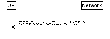
Figure 5.7.1a.1-1: DL information transfer MR-DC
The purpose of this procedure is to
transfer RRC messages from the network to the UE over SRB3 (e.g. an NR RRC
reconfiguration message including reconfigurationWithSync, an E-UTRA RRC
connection reconfiguration message including mobilityControlInfo, an RRC
connection release message, a MobilityFromNRCommand message, or a MobilityFromEUTRACommand
message) during fast MCG link recovery.
The network initiates this procedure
whenever there is a need to transfer an RRC message during fast MCG link
recovery.
Upon receiving the DLInformationTransferMRDC,
the UE shall:
1> if the RRCReconfiguration message is
included in dl-DCCH-MessageNR:
2> perform the RRC reconfiguration procedure
according to 5.3.5.3;
1> else if the RRCRelease message is
included in dl-DCCH-MessageNR:
2> perform the RRC release procedure according
to 5.3.8;
1> else if the MobilityFromNRCommand
message is included in the dl-DCCH-MessageNR:
2> perform the mobility from NR procedure
according to 5.4.3.3;
1> else if the E-UTRA RRCConnectionReconfiguration
message is included in dl-DCCH-MessageEUTRA:
2> perform the RRC connection reconfiguration
procedure as specified in TS 36.331 [10], clause 5.3.5.4;
1> else if the E-UTRA RRCConnectionRelease
message is included in dl-DCCH-MessageEUTRA:
2> perform the RRC connection release as
specified in TS 36.331 [10], clause 5.3.8;
1> else if the MobilityFromEUTRACommand
message is included in the dl-DCCH-MessageEUTRA:
2> perform the mobility from E-UTRA procedure
as specified in TS 36.331 [10], clause 5.4.3.3;

Figure 5.7.2.1-1: UL information transfer
The purpose of this procedure is to
transfer NAS dedicated information from the UE to the network in RRC_CONNECTED
or in RRC_INACTIVE during SDT, or to transfer F1-C related information from
IAB-DU to IAB Donor-CU via the collocated IAB-MT in RRC_CONNECTED.
A UE in RRC_CONNECTED or a UE in
RRC_INACTIVE during SDT initiates the UL information transfer procedure
whenever there is a need to transfer NAS dedicated information. The UE
initiates the UL information transfer procedure by sending the
ULInformationTransfer message. In addition, an IAB-MT in RRC_CONNECTED
initiates the UL information transfer procedure whenever there is a need to
transfer F1-C related information. When F1-C related information has to be
transferred, the IAB-MT shall initiate the procedure only if SRB2 or split SRB2
is established.
The UE shall set the contents of the ULInformationTransfer
message as follows:
1> if the upper layer provides NAS PDU:
2> set the dedicatedNAS-Message to
include the information received from upper layers;
1> for the IAB-MT, if there is a need to
transfer F1-C related information:
2> include the dedicatedInfoF1c;
1> submit the ULInformationTransfer
message to lower layers for transmission, upon which the procedure ends.
The UE shall:
1> if AS security is not started and radio link
failure occurs before the successful delivery of ULInformationTransfer
messages has been confirmed by lower layers; or
1> if PDCP re-establishment or release/addition
(e.g due to key refresh upon PCell or PSCell change, or RRC connection
re-establishment, or failure of resume procedure initiated for SDT) occurs on
an SRB on which ULInformationTransfer messages were submitted for
transmission but successful delivery of these messages was not confirmed by
lower layers:
2> inform upper layers about the possible
failure to deliver the information contained in the concerned ULInformationTransfer
messages, unless the messages only include dedicatedInfoF1c.
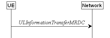
Figure 5.7.2a.1-1: UL information transfer MR-DC
The purpose of this procedure is to
transfer MR-DC dedicated information from the UE to the network e.g. the NR or
E-UTRA RRC MeasurementReport, FailureInformation,
UEAssistanceInformation, RRCReconfigurationComplete, MCGFailureInformation,
or IABOtherInformation message.
A UE in RRC_CONNECTED initiates the UL
information transfer for MR-DC procedure whenever there is a need to transfer
MR-DC dedicated information. I.e. the procedure is not used during an RRC
connection reconfiguration involving NR or E-UTRA connection reconfiguration,
in which case the MR DC information is piggybacked to the RRCReconfigurationComplete
message, except in the case the
UE executes an intra-SN CPC.
The UE shall set the contents of the ULInformationTransferMRDC
message as follows:
1> if there is a need to transfer MR-DC
dedicated information related to NR:
2> set the ul-DCCH-MessageNR to include
the NR MR-DC dedicated information to be transferred (e.g., NR RRC MeasurementReport,
UEAssistanceInformation, FailureInformation,
RRCReconfigurationComplete, MCGFailureInformation, or IABOtherInformation
message);
1> else if there is a need to transfer MR-DC
dedicated information related to E-UTRA:
2> set the ul-DCCH-MessageEUTRA to
include the E-UTRA MR-DC dedicated information to be transferred (e.g., E-UTRA
RRC MeasurementReport, or MCGFailureInformation message);
1> submit the ULInformationTransferMRDC
message to lower layers for transmission, upon which the procedure ends.
Figure 5.7.2b.1-1: UL transfer of IRAT information
The purpose of this procedure is to
transfer from the UE to NR MCG dedicated information terminated at the NR MCG
but specified by another RAT e.g. the E-UTRA MeasurementReport message,
the E-UTRA SidelinkUEInformation message or the E-UTRA UEAssistanceInformation
message. The specific information transferred in this message is set in
accordance with:
- the procedure specified in 5.6.10 of TS
36.331 [10] for E-UTRA UEAssistanceInformation message;
- the procedure specified in 5.10.2 of TS
36.331 [10] for E-UTRA SidelinkUEInformation message;
- the procedure specified in 5.5.5 of TS 36.331
[10] for E-UTRA MeasurementReport Message.
A UE in RRC_CONNECTED initiates the UL
information transfer procedure whenever there is a need to transfer dedicated
inter-RAT information as specified in TS 36.331 [10].
The UE shall set the contents of the ULInformationTransferIRAT
message as follows:
1> if there is a need to transfer dedicated LTE
information related to V2X sidelink communications:
2> set the ul-DCCH-MessageEUTRA to
include the V2X sidelink communication information to be transferred (e.g. the
E-UTRA RRC MeasurementReport message, the E-UTRA RRC SidelinkUEInformation
message, or the E-UTRA RRC UEAssistanceInformation message);
1> submit the ULInformationTransferIRAT
message to lower layers for transmission, upon which the procedure ends;
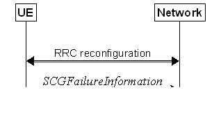
Figure 5.7.3.1-1: SCG failure information
The purpose of this procedure is to inform
E-UTRAN or NR MN about an SCG failure the UE has experienced i.e. SCG radio
link failure, beam failure of the PSCell while the SCG is deactivated, failure
of SCG reconfiguration with sync, SCG configuration failure for RRC message on
SRB3, SCG integrity check failure, and consistent
uplink LBT failures on PSCell for operation with shared spectrum channel access.
A UE initiates the procedure to report SCG
failures when neither MCG nor SCG transmission is suspended and when one of the
following conditions is met:
1> upon detecting radio link failure for the
SCG, in accordance with clause 5.3.10.3;
1> upon detecting beam failure of the PSCell
while the SCG is deactivated, in accordance with TS 38.321[3];
1> upon reconfiguration with sync failure of
the SCG, in accordance with clause 5.3.5.8.3;
1> upon SCG configuration failure, in
accordance with clause 5.3.5.8.2;
1> upon integrity check failure indication from
SCG lower layers concerning SRB3.
Upon initiating the procedure, the UE
shall:
1> if the procedure was not initiated due to
beam failure of the PSCell while the SCG is deactivated:
2> suspend SCG transmission for all SRBs, DRBs
and, if any, BH RLC channels;
2> reset SCG MAC;
1> stop T304 for the SCG, if running;
1> stop conditional reconfiguration evaluation
for CPC, CPA, or subsequent CPAC, if configured;
1> stop conditional reconfiguration evaluation
for each CHO configuration that includes condExecutionCondPSCell, if
configured;
1> if the UE is in (NG)EN-DC:
2> initiate transmission of the SCGFailureInformationNR
message as specified in TS 36.331 [10], clause 5.6.13a.
1> else:
2> initiate transmission of the SCGFailureInformation
message in accordance with 5.7.3.5.
The UE shall set the SCG failure type as
follows:
1> if the UE initiates transmission of the SCGFailureInformationNR
message due to T310 expiry:
2> set the failureType as t310-Expiry;
1> else if the UE initiates transmission of the
SCGFailureInformationNR message due to T312 expiry:
2> set the failureType as any value and
set the failureType-v1610 as t312-Expiry;
1> else if the UE initiates transmission of the
SCGFailureInformationNR message to provide reconfiguration with sync
failure information for an SCG:
2> set the failureType as synchReconfigFailureSCG;
1> else if the UE initiates transmission of the
SCGFailureInformationNR message to provide random access problem
indication from SCG MAC:
2> if the random access procedure was initiated
for beam failure recovery:
3> set the failureType as randomAccessProblem
and set the failureType-v1610 as beamFailureRecoveryFailure;
2> else:
3> set the failureType as randomAccessProblem;
1> else if the UE initiates transmission of the
SCGFailureInformationNR message to provide indication from SCG RLC that
the maximum number of retransmissions has been reached:
2> set the failureType as rlc-MaxNumRetx;
1> else if the UE initiates transmission of the
SCGFailureInformationNR message due to SRB3 integrity check failure:
2> set the failureType as srb3-IntegrityFailure;
1> else if the UE initiates transmission of the
SCGFailureInformationNR message due to Reconfiguration failure of NR RRC
reconfiguration message:
2> set the failureType as scg-reconfigFailure;
1> else if the UE
initiates transmission of the SCGFailureInformationNR message due to
consistent uplink LBT failures:
2> set the failureType as any value and
set the failureType-v1610 as scg-lbtFailure;
1> else if connected as an IAB-node and the SCGFailureInformationNR
is initiated due to the reception of a BH RLF indication on BAP entity from the
SCG:
2> set the failureType as any value and
set failureType-v1610 as bh-RLF.
1> else if the UE
initiates transmission of the SCGFailureInformationNR message due to
beam failure of the PSCell while the SCG is deactivated:
2> set the failureType as any value and
set failureType-v1610 as beamFailure.
The UE shall set the contents of the MeasResultSCG-Failure
as follows:
1> for each MeasObjectNR configured on
NR SCG for which a measId is configured and measurement results are
available:
2> include an entry in measResultPerMOList;
2> if there is a measId configured with
the MeasObjectNR and a reportConfig which has rsType set
to ssb:
3> set ssbFrequency to the value
indicated by ssbFrequency as included in the MeasObjectNR;
2> if there is a measId configured with
the MeasObjectNR and a reportConfig which has rsType set
to csi-rs:
3> set refFreqCSI-RS to the value
indicated by refFreqCSI-RS as included in the associated measurement
object;
2> if a serving cell is associated with the MeasObjectNR:
3> set measResultServingCell to include
the available quantities of the concerned cell and in accordance with the
performance requirements in TS 38.133 [14];
2> set the measResultNeighCellList to
include the best measured cells, ordered such that the best cell is listed
first, and based on measurements collected up to the moment the UE detected the
failure, and set its fields as follows;
3> ordering the cells with sorting as follows:
4> based on SS/PBCH block if SS/PBCH block
measurement results are available and otherwise based on CSI-RS;
4> using RSRP if RSRP measurement results are
available, otherwise using RSRQ if RSRQ measurement results are available,
otherwise using SINR;
3> for each neighbour cell included:
4> include the optional fields that are
available.
3> if the UE supports SCG failure information for mobility robustness optimization for conditional PSCell change, for each
neighbour cell, if any, included in measResultSCG-Failure:
4> if the neighbour
cell is one of the candidate cells for which the reconfigurationWithSync
is included in the secondaryCellGroup in the MCG VarConditionalReconfig
(for inter-SN CPC in NR-DC) or SCG VarConditionalReconfig (for intra-SN
CPC) at the moment of the
detected SCG failure (radio link failure at PSCell or PSCell change failure):
5> if the first entry of condExecutionCond
or condExecutionCondSCG associated to the neighbour cell corresponds to
a fulfilled execution condition at the moment of SCG
failure; or
5> if the second entry of condExecutionCond or condExecutionCondSCG associated to the neighbour cell, if available, corresponds to a
fulfilled execution condition at the moment of SCG
failure:
6> set firstTriggeredEvent to the
execution condition condFirstEvent corresponding to the first entry of condExecutionCond
or condExecutionCondSCG associated to the neighbour cell or to the
execution condition condSecondEvent corresponding to the second entry of
condExecutionCond or condExecutionCondSCG associated to the
neighbour cell, whichever execution
condition was fulfilled first in time;
6> set timeBetweenEvents
to the elapsed time between the point in time of
fulfilling the condition in condExecutionCond or
condExecutionCondSCG associated to the neighbour cell that was fulfilled first in time, and
the point in time of fulfilling the condition in condExecutionCond
or condExecutionCondSCG associated to the neighbour cell that was fulfilled second in time, if
both the first execution condition corresponding to the first entry and the
second execution condition corresponding to the second entry in the condExecutionCond or condExecutionCondSCG associated to the
neighbour cell were
fulfilled;
NOTE: The measured quantities are filtered by
the L3 filter as configured in the mobility measurement configuration. The
measurements are based on the time domain measurement resource restriction, if
configured. Exclude-listed cells are not required to be reported.
1> if available, set the locationInfo as
in 5.3.3.7 according to the otherConfig associated with the NR SCG.
The UE shall set the contents of the SCGFailureInformation
message as follows:
1> if the UE initiates transmission of the SCGFailureInformation
message due to T310 expiry:
2> set the failureType as t310-Expiry;
1> else if the UE initiates transmission of the
SCGFailureInformation message due to T312 expiry:
2> set the failureType as other
and set the failureType-v1610 as t312-Expiry;
1> else if the UE initiates transmission of the
SCGFailureInformation message to provide reconfiguration with sync
failure information for an SCG:
2> set the failureType as synchReconfigFailureSCG;
1> else if the UE initiates transmission of the
SCGFailureInformation message to provide random access problem
indication from SCG MAC:
2> if the random access procedure was initiated
for beam failure recovery:
3> set the failureType as other
and set the failureType-v1610 as beamFailureRecoveryFailure;
2> else:
3> set the failureType as randomAccessProblem;
1> else if the UE initiates transmission of the
SCGFailureInformation message to provide indication from SCG RLC that
the maximum number of retransmissions has been reached:
2> set the failureType as rlc-MaxNumRetx;
1> else if the UE initiates transmission of the
SCGFailureInformation message due to SRB3 IP check failure:
2> set the failureType as srb3-IntegrityFailure;
1> else if the UE initiates transmission of the
SCGFailureInformation message due to Reconfiguration failure of NR RRC
reconfiguration message:
2> set the failureType as scg-reconfigFailure;
1> else if the UE
initiates transmission of the SCGFailureInformation message due to
consistent uplink LBT failures:
2> set the failureType as other
and set the failureType-v1610 as scg-lbtFailure;
1> else if connected as an IAB-node and the SCGFailureInformation
is initiated due to the reception of a BH RLF indication on BAP entity from the
SCG:
2> set the failureType as other
and set failureType-v1610 as bh-RLF;
1> else if the UE initiates transmission of the
SCGFailureInformation message due to beam failure of the PSCell while
the SCG is deactivated:
2> set the failureType as other
and set failureType-v1610 as beamFailure;
1> include and set MeasResultSCG-Failure
in accordance with 5.7.3.4;
1> for each MeasObjectNR configured by a
MeasConfig associated with the MCG, and for which measurement results
are available:
2> include an entry in measResultFreqList;
2> if there is a measId configured with
the MeasObjectNR and a reportConfig which has rsType set
to ssb:
3> set ssbFrequency in measResultFreqList
to the value indicated by ssbFrequency as included in the MeasObjectNR;
2> if there is a measId configured with
the MeasObjectNR and a reportConfig which has rsType set
to csi-rs:
3> set refFreqCSI-RS in measResultFreqList
to the value indicated by refFreqCSI-RS as included in the associated
measurement object;
2> if a serving cell is associated with the MeasObjectNR:
3> set measResultServingCell in measResultFreqList
to include the available quantities of the concerned cell and in accordance
with the performance requirements in TS 38.133 [14];
2> set the measResultNeighCellList in measResultFreqList
to include the best measured cells, ordered such that the best cell is listed
first, and based on measurements collected up to the moment the UE detected the
failure, and set its fields as follows;
3> ordering the cells with sorting as follows:
4> based on SS/PBCH block if SS/PBCH block
measurement results are available and otherwise based on CSI-RS;
4> using RSRP if RSRP measurement results are
available, otherwise using RSRQ if RSRQ measurement results are available,
otherwise using SINR;
3> if the UE supports SCG failure information for mobility robustness optimization for conditional PSCell change or addition, for
each neighbour cell, if any, included in measResultListNR in measResultFreqList:
4> if the neighbour
cell is one of the candidate cells for which the reconfigurationWithSync
is included in the secondaryCellGroup in the MCG VarConditionalReconfig
(for CPA or inter-SN CPC in NR-DC) or SCG VarConditionalReconfig (for
intra-SN CPC) at the moment of
the detected SCG failure (radio link failure at PSCell or PSCell change or
addition failure):
5> if the first entry of condExecutionCond
or condExecutionCondSCG associated to the neighbour cell corresponds to
a fulfilled execution condition at the moment of SCG
failure; or
5> if the second entry of condExecutionCond
or condExecutionCondSCG associated to the neighbour cell, if available,
corresponds to a fulfilled execution condition at the
moment of SCG failure:
6> set firstTriggeredEvent to the
execution condition condFirstEvent corresponding to the first entry of condExecutionCond
or condExecutionCondSCG associated to the neighbour cell or to the
execution condition condSecondEvent corresponding to the second entry of
condExecutionCond or condExecutionCondSCG associated to the
neighbour cell, whichever execution
condition was fulfilled first in time;
6> set timeBetweenEvents
to the elapsed time between the point in time of
fulfilling the condition in condExecutionCond or
condExecutionCondSCG associated to the neighbour cell that was fulfilled first in time, and the point in time of
fulfilling the condition in condExecutionCond or
condExecutionCondSCG associated to the neighbour cell that was fulfilled second in time, if both the first execution
condition corresponding to the first entry and the second execution condition
corresponding to the second entry in the condExecutionCond or condExecutionCondSCG associated to the neighbour cell were fulfilled;
3> for each neighbour cell included:
4> include the optional fields that are
available.
NOTE 1: The measured quantities are filtered by
the L3 filter as configured in the mobility measurement configuration. The
measurements are based on the time domain measurement resource restriction, if
configured. Exclude-listed cells are not required to be reported.
NOTE 2: Field measResultSCG-Failure is
used to report available results for NR frequencies the UE is configured to
measure by SCG RRC signalling.
1> if available, set the locationInfo as
in 5.3.3.7 according to the otherConfig associated with the NR MCG.
1> if the UE supports SCG failure for mobility
robustness optimization:
2> if the failureType is set to synchReconfigFailureSCG;
or
2> if the failureType is set to randomAccessProblem
and the SCG failure was declared while T304 was running:
3> set perRAInfoList to indicate the performed
random access procedure related information as specified in 5.7.10.5.
3> set the failedPSCellId to the
physical cell identity and carrier frequency of the target PSCell of the failed
PSCell change or failed PSCell addition;
3> set the previousPSCellId
to the physical cell identity and carrier frequency of the source PSCell associated
to the last received RRCReconfiguration message including reconfigurationWithSync
for the SCG, if available;
3> set the timeSCGFailure
to the elapsed time since the last execution of RRCReconfiguration
message including the reconfigurationWithSync for the SCG until
declaring the SCG failure;
2> else:
3> set the failedPSCellId to the
physical cell identity and carrier frequency of the PSCell in which the SCG
failure was declared;
3> if the last RRCReconfiguration
message including the reconfigurationWithSync for the SCG was received
to enter the PSCell in which the SCG failure was declared:
4> set the timeSCGFailure to the elapsed
time since the last execution of RRCReconfiguration message including
the reconfigurationWithSync for the SCG until declaring the SCG failure;
4> set the previousPSCellId
to the physical cell identity and carrier frequency of the source PSCell associated
to the last received RRCReconfiguration message including reconfigurationWithSync
for the SCG;
1> release successPSCell-Config
configured by the source PSCell, if available.
The UE shall submit the SCGFailureInformation
message to lower layers for transmission.
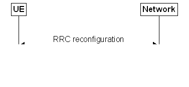
Figure 5.7.3a.1-1: EUTRA SCG failure information
The purpose of this procedure is to inform
NR MN about an SCG failure on E-UTRA SN the UE has experienced (e.g. SCG radio
link failure, SCG change failure), as specified in TS 36.331 [10] clause
5.6.13.2.
A UE initiates the procedure to report
EUTRA SCG failures when neither NR MCG nor EUTRA SCG transmission is suspended
and in accordance with TS 36.331 [10] clause 5.6.13.2. Actions the UE shall
perform upon initiating the procedure, other than related to the transmission
of the SCGFailureInformationEUTRA message are specified in TS 36.331
[10] clause 5.6.13.2.
The UE shall set the contents of the SCGFailureInformationEUTRA
message as follows:
1> include failureType within failureReportSCG-EUTRA
and set it to indicate the SCG failure in accordance with TS 36.331 [10] clause
5.6.13.4;
1> include and set measResultSCG-FailureMRDC
in accordance with TS 36.331 [10] clause 5.6.13.5;
1> for each EUTRA frequency the UE is
configured to measure by measConfig for which measurement results are
available:
2> set the measResultFreqListMRDC to
include the best measured cells, ordered such that the best cell is listed
first using RSRP to order if RSRP measurement results are available for cells
on this frequency, otherwise using RSRQ to order if RSRQ measurement results
are available for cells on this frequency, otherwise using SINR to order, and
based on measurements collected up to the moment the UE detected the failure,
and for each cell that is included, include the optional fields that are
available;
NOTE: Field measResultSCG-FailureMRDC
is used to report available results for E-UTRAN frequencies the UE is
configured to measure by E-UTRA RRC signalling.
1> if available, set the locationInfo as
in 5.3.3.7.:
The UE shall submit the SCGFailureInformationEUTRA
message to lower layers for transmission.

Figure 5.7.3b.1-1: MCG failure information
The purpose of this procedure is to inform
the network about an MCG failure the UE has experienced i.e. MCG radio link
failure. A UE in RRC_CONNECTED, for which AS security has been activated with
SRB2 and at least one DRB or multicast MRB setup or, for IAB, SRB2, may
initiate the fast MCG link recovery procedure in order to continue the RRC
connection without re-establishment.
In case of MR-DC, a
UE configured with split SRB1 or SRB3 initiates the procedure to report MCG
failures when neither MCG nor SCG transmission is suspended, the SCG is not
deactivated, t316 is configured, and when the following condition is met;
or
In case of MP, a MP remote UE configured with
split SRB1 initiates the procedure to report direct path failures when neither
MCG (i.e. direct path) nor indirect path transmission is suspended, t316
is configured, and when the following condition is met:
1> upon detecting radio link failure of the
MCG, in accordance with 5.3.10.3, while T316 is not running.
Upon initiating the procedure, the UE shall:
1> stop timer T310 for the PCell, if running;
1> stop timer T312 for the PCell, if running;
1> suspend MCG transmission for all SRBs, DRBs,
multicast MRBs, except SRB0, and, if any, BH RLC channels;
1> reset MCG MAC;
1> stop conditional reconfiguration evaluation
for CHO or CHO with candidate SCG(s), if configured;
1> stop conditional reconfiguration evaluation
for CPC or subsequent CPAC, if configured;
1> initiate transmission of the MCGFailureInformation
message in accordance with 5.7.3b.4.
NOTE: The handling of any outstanding UL RRC
messages during the initiation of the fast MCG link recovery is left to UE
implementation.
The UE shall set the MCG failure type as
follows:
1> if the UE initiates transmission of the MCGFailureInformation
message due to T310 expiry:
2> set the failureType as t310-Expiry;
1> else if the UE initiates transmission of the
MCGFailureInformation message due to T312 expiry:
2> set the failureType as t312-Expiry;
1> else if the UE initiates transmission of the
MCGFailureInformation message to provide random access problem
indication from MCG MAC:
2> if the random access procedure was initiated
for beam failure recovery:
3> set the failureType as beamFailureRecoveryFailure;
2> else:
3> set the failureType as randomAccessProblem;
1> else if the UE initiates transmission of the
MCGFailureInformation message to provide indication from MCG RLC that
the maximum number of retransmissions has been reached:
2> set the failureType as rlc-MaxNumRetx:
1> else if the UE
initiates transmission of the MCGFailureInformation message due to
consistent uplink LBT failures on the MCG:
2> set the failureType as lbt-Failure;
1> else if connected as an IAB-node and the MCGFailureInformation
message is initiated due to the reception of a BH RLF indication on BAP entity
from the MCG:
2> set the failureType as bh-RLF.
5.7.3b.4 Actions related to transmission of MCGFailureInformation message
The UE shall set the contents of the MCGFailureInformation
message as follows:
1> include and set failureType in
accordance with 5.7.3b.3;
1> for each MeasObjectNR configured by a
measConfig associated with the MCG, and for which measurement results
are available:
2> include an entry in measResultFreqList;
2> if there is a measId configured with
the MeasObjectNR and a reportConfig which has rsType set
to ssb:
3> set ssbFrequency in measResultFreqList
to the value indicated by ssbFrequency as included in the MeasObjectNR;
2> if there is a measId configured with
the MeasObjectNR and a reportConfig which has rsType set
to csi-rs:
3> set refFreqCSI-RS in measResultFreqList
to the value indicated by refFreqCSI-RS as included in the associated
measurement object;
2> if a serving cell is associated with the MeasObjectNR:
3> set measResultServingCell in measResultFreqList
to include the available quantities of the concerned cell and in accordance
with the performance requirements in TS 38.133 [14];
2> set the measResultNeighCellList in measResultFreqList
to include the best measured cells, ordered such that the best cell is listed
first, and based on measurements collected up to the moment the UE detected the
failure, and set its fields as follows;
3> ordering the cells with sorting as follows:
4> based on SS/PBCH block if SS/PBCH block
measurement results are available and otherwise based on CSI-RS;
4> using RSRP if RSRP measurement results are
available, otherwise using RSRQ if RSRQ measurement results are available,
otherwise using SINR;
3> for each neighbour cell included:
4> include the optional fields that are
available.
1> for each EUTRA frequency the UE is
configured to measure by measConfig for which measurement results are
available:
2> set the measResultFreqListEUTRA to
include the best measured cells, ordered such that the best cell is listed
first using RSRP to order the cells if RSRP measurement results are available
for cells on this frequency, otherwise using RSRQ to order the cells if RSRQ
measurement results are available for cells on this frequency, otherwise using
SINR to order the cells, based on measurements collected up to the moment the
UE detected the failure, and for each cell that is included, include the
optional fields that are available;
1> for each UTRA-FDD frequency the UE is
configured to measure by measConfig for which measurement results are
available:
2> set the measResultFreqListUTRA-FDD to
include the best measured cells, ordered such that the best cell is listed
first using RSCP to order the cells if RSCP measurement results are available
for cells on this frequency, otherwise using EcN0 to order the cells, based on
measurements collected up to the moment the UE detected the failure, and for
each cell that is included, include the optional fields that are available;
1> if the UE is in NR-DC:
2> include and set measResultSCG in
accordance with 5.7.3.4;
1> if the UE is in NE-DC:
2> include and set measResultSCG-EUTRA
in accordance with TS 36.331 [10] clause 5.6.13.5;
NOTE 1: The measured quantities are filtered by
the L3 filter as configured in the mobility measurement configuration. The
measurements are based on the time domain measurement resource restriction, if
configured. Exclude-listed cells are not required to be reported.
NOTE 2: Field measResultSCG-Failure is
used to report available results for NR frequencies the UE is configured to
measure by SCG RRC signalling.
NOTE 3: Field measResultSCG-EUTRA is used
to report available results for E-UTRAN frequencies the UE is configured to
measure by E-UTRA RRC signalling.
1> if SRB1 is configured as split SRB and pdcp-Duplication
is not configured:
2> if the primaryPath for the PDCP
entity of SRB1 refers to the direct path when MP is configured:
3> set the primaryPath to refer to the
indirect path;
2> else if the primaryPath for the PDCP
entity of SRB1 refers to the MCG:
3> set the primaryPath to refer to the
SCG.
The UE shall:
1> start timer T316;
1> if SRB1 is configured as split SRB:
2> submit the MCGFailureInformation message
to lower layers for transmission via SRB1, upon which the procedure ends;
1> else (i.e. SRB3 configured):
2> submit the MCGFailureInformation
message to lower layers for transmission embedded in NR RRC message ULInformationTransferMRDC
via SRB3 as specified in 5.7.2a.3.
The UE shall:
1> if T316 expires:
2> if the UE supports RLF-Report for fast MCG
recovery procedure:
3> set the pSCellId in the VarRLF-Report
to the global cell identity of the PSCell, if available, otherwise to the
physical cell identity and carrier frequency of the PSCell;
3> set the mcg-RecoveryFailureCause
in VarRLF-Report to t316-Expiry;
2> initiate the connection re-establishment
procedure as specified in 5.3.7.
Figure 5.7.3c.1-1: Indirect path failure
information
The purpose of this procedure is to inform the network about an indirect path failure
the MP remote UE has experienced.
In case of MP, a MP remote UE initiates the
procedure to report indirect path failures when neither MCG transmission nor
indirect path transmission is suspended and when one of the following
conditions is met:
1> upon detecting a SL indirect path failure
resulting from sidelink radio link failure on the PC5 unicast link or reception
of NotificationMessageSidelink from the L2 U2N Relay UE (except indicating relayUE-HO), or SL indirect path
addition/change failure in accordance with 5.3.5.17.2.3, or PC5-RRC connection release requested by upper layers in accordance with clause 5.8.9.5; or
1> upon detecting a N3C indirect path failure,
including N3C connection failure or Uu failure of the N3C relay UE with N3C
indirect path, or N3C indirect path addition/change failure in accordance with
5.3.5.17.3.2a;
Upon initiating the procedure, the UE
shall:
1> if the procedure was initiated to report SL
indirect path failure:
2> reset the sidelink specific MAC of the L2
U2N relay UE;
2> stop T421 if running;
1> suspend indirect path transmission for all
SRBs and DRBs;
1> initiate transmission of the IndirectPathFailureInformation
message in accordance with 5.7.3c.4;
The L2 U2N Remote
UE configured with SL indirect path shall set the indirect path failure type as
follows:
1> if the UE initiates transmission of the IndirectPathFailureInformation
message due to T421 expiry in accordance with clause 5.3.5.16.1.3:
2> set the failureTypeIndirectPath as t421-Expiry;
1> else if the UE initiates transmission of the
IndirectPathFailureInformation message due to reception of the NotificationMessageSidelink including indicationType,
in accordance with clause 5.8.9.10.4:
2> set the failureTypeIndirectPath as
the value in indicationType received from NotificationMessageSidelink
(except relayUE-CellReselection);
1> else if the UE initiates transmission of the
IndirectPathFailureInformation message due to sidelink radio link
failure in accordance with clause 5.8.9.3:
2> set the failureTypeIndirectPath as
sl-Failure;
1> else if the UE initiates transmission of the
IndirectPathFailureInformation message due to PC5-RRC
connection release requested by upper layers in
accordance with clause 5.8.9.5:
2> set the failureTypeIndirectPath as
sl-PC5-Release;
1> else if the UE initiates transmission of the
IndirectPathFailureInformation message due to that the (target) L2 U2N
Relay UE (i.e., the UE indicated by sl-IndirectPathRelayUE-Identity in
the received sl-IndirectPathAddChange) changes its serving cell to a
different cell from the target cell (i.e. the cell indicated by sl-IndirectPathCellIdentity
in the received sl-IndirectPathAddChange) during path addition or
change:
2> set the failureTypeIndirectPath as indirectPathAddChangeFailure;
The N3C remote UE
shall set the indirect path failure type as follows:
1> if the UE initiates transmission of the IndirectPathFailureInformation
message due to N3C connection failure:
2> set the failureTypeIndirectPath as n3c-Failure;
1> else if the UE initiates transmission of the
IndirectPathFailureInformation message due to Uu radio link failure on
N3C indirect path in accordance with clause 5.3.10.3:
2> set the failureTypeIndirectPath as relayUE-Uu-RLF;
1> if the UE initiates transmission of the IndirectPathFailureInformation
message due to N3C Indirect path addition/change failure in accordance with
clause 5.3.5.17.3.2a:
2> set the failureTypeIndirectPath as indirectPathAddChangeFailure.
NOTE: It is out of 3GPP scope how the remote
UE detects N3C connection failure, or how the relay UE indicates Uu RLF to the
remote UE on the N3C connection.
The UE shall set
the contents of the IndirectPathFailureInformation message as follows:
1> set the failureTypeIndirectPath in
accordance with 5.7.3c.3;
1> if the procedure was
initiated to report SL indirect path failure:
2> set the sl-MeasResultServingRelay to
include the measurement result for serving L2 U2N Relay UE if available;
2> for each measObjectRelay included in MeasConfig,
and for which measurement results are available:
3> include an entry in sl-MeasResultsCandRelay;
1> else if the
procedure was initiated to report N3C indirect path failure;
2> include n3c-relayUE-InfoList to report relay UE information with
non-3GPP connection(s) if available;
1> submit the IndirectPathFailureInformation
message to lower layers for transmission.

Figure 5.7.4.1-1: UE Assistance Information
The purpose of this procedure is for the UE
to inform the network of:
- its delay budget report carrying desired
increment/decrement in the connected mode DRX cycle length; or
- its overheating assistance information; or
- its IDC assistance information; or
- its preference on DRX parameters for power
saving; or
- its preference on the maximum aggregated
bandwidth for power saving; or
- its preference on the maximum number of
secondary component carriers for power saving; or
- its preference on the maximum number of MIMO
layers for power saving; or
- its preference on the minimum scheduling
offset for cross-slot scheduling for power saving; or
- its preference on the RRC state; or
- configured grant assistance information for
NR sidelink communication; or
- its preference in being provisioned with
reference time information; or
- its preference for FR2 UL gap; or
- its preference to transition out of
RRC_CONNECTED state for MUSIM operation; or
- its preference on the MUSIM gaps; or
- its preference on the
MUSIM gap priority; or
- its preference on keeping the colliding MUSIM gaps; or
- its preference on the MUSIM temporary
capability restriction; or
- its relaxation state for RLM measurements; or
- its relaxation state for BFD measurements; or
- availability of data and/or signalling mapped
to radio bearers which are not configured for SDT; or
- its preference for the SCG to be deactivated;
or
- availability of uplink data to transmit for a
DRB for which there is no MCG RLC bearer while the SCG is deactivated; or
- change of its fulfilment status for RRM
measurement relaxation criterion; or
- service link (specified in TS 38.300 [2])
propagation delay difference between serving cell and neighbour cell(s); or
- its preference on multi-Rx
operation for FR2; or
- availability of flight path information for
Aerial UE operation; or
- UL traffic information; or
- the information of
the relay UE(s) with which it connects via a non-3GPP connection for MP; or
- configured grant assistance information for
NR sidelink positioning.
A UE capable of providing delay budget
report in RRC_CONNECTED may initiate the procedure in several cases, including
upon being configured to provide delay budget report and upon change of delay
budget preference.
A UE capable of providing overheating
assistance information in RRC_CONNECTED may initiate the procedure if it was
configured to do so, upon detecting internal overheating, or upon detecting
that it is no longer experiencing an overheating condition.
A UE capable of providing IDC assistance
information in RRC_CONNECTED may initiate the procedure if it was configured to
do so, upon detecting IDC problem if the UE did not transmit an IDC assistance
information since it was configured to provide IDC indications, or upon change
of IDC problem information.
A UE capable of providing its preference on
DRX parameters of a cell group for power saving in RRC_CONNECTED may initiate
the procedure in several cases, if it was configured to do so, including upon
having a preference on DRX parameters and upon change of its preference on DRX
parameters.
A UE capable of providing its preference on
the maximum aggregated bandwidth of a cell group for power saving in
RRC_CONNECTED may initiate the procedure in several cases, if it was configured
to do so, including upon having a maximum aggregated bandwidth preference and
upon change of its maximum aggregated bandwidth preference.
A UE capable of providing its preference on
the maximum number of secondary component carriers of a cell group for power
saving in RRC_CONNECTED may initiate the procedure in several cases, if it was
configured to do so, including upon having a maximum number of secondary
component carriers preference and upon change of its maximum number of
secondary component carriers preference.
A UE capable of providing its preference on
the maximum number of MIMO layers of a cell group for power saving in
RRC_CONNECTED may initiate the procedure in several cases, if it was configured
to do so, including upon having a maximum number of MIMO layers preference and
upon change of its maximum number of MIMO layers preference.
A UE capable of providing its preference on
the minimum scheduling offset for cross-slot scheduling of a cell group for
power saving in RRC_CONNECTED may initiate the procedure in several cases, if
it was configured to do so, including upon having a minimum scheduling offset
preference and upon change of its minimum scheduling offset preference.
A UE capable of providing assistance
information to transition out of RRC_CONNECTED state may initiate the procedure
if it was configured to do so, upon determining that it prefers to transition
out of RRC_CONNECTED state, or upon change of its preferred RRC state.
A UE capable of providing configured grant
assistance information for NR sidelink communication in RRC_CONNECTED may
initiate the procedure in several cases, including upon being configured to
provide traffic pattern information and upon change of traffic patterns.
A UE capable of providing an indication of
its preference in being provisioned with reference time information may
initiate the procedure upon being configured to provide this indication, or if
it was configured to provide this indication and upon change of its preference.
A UE capable of providing an indication of
its preference in FR2 UL gap may initiate the procedure if it was configured to
do so, upon detecting the need of FR2 UL gap activation/deactivation.
A UE capable of providing MUSIM assistance
information for gap preference may initiate the procedure if it was configured
to do so, upon determining it
needs the gaps, or upon change of the gap preference information.
A UE capable of providing MUSIM assistance
information for gap priority preference and/or preference to keep the colliding
MUSIM gaps may initiate the procedure if it was configured to do so, upon determining it has gap priority
preference information and/or it has preference to keep the colliding MUSIM gaps.
A UE capable of providing MUSIM assistance
information for leave indication may initiate the procedure if it was
configured to do so upon determining that it needs to leave RRC_CONNECTED
state.
A UE capable of providing MUSIM assistance
information for temporary capability restriction may initiate the procedure if
it was configured to do so, upon
determining it has temporary capability restriction or upon determining the
removal of the capability restriction.
A UE capable of relaxing
its RLM measurements of a cell group in RRC_CONNECTED
state shall initiate the procedure for providing an indication of its
relaxation state for RLM measurements upon being configured to do so, and upon
change of its relaxation state for RLM measurements in RRC_CONNECTED state.
A UE capable of relaxing its BFD measurements in serving cells of a cell group in
RRC_CONNECTED shall initiate the procedure for providing an indication of its
relaxation state for BFD measurements upon being configured to do so, and upon
change of its relaxation state for BFD measurements in RRC_CONNECTED state.
A UE capable of SDT initiates this
procedure when data and/or signalling mapped to radio bearers that are not
configured for SDT becomes available during SDT (i.e. while SDT procedure is
ongoing).
A UE capable of providing its preference
for SCG deactivation may initiate the procedure if it was configured to do so,
upon determining that it prefers or does no more prefer the SCG to be
deactivated.
A UE that has uplink data to transmit for a
DRB for which there is no MCG RLC bearer while the SCG is deactivated shall
initiate the procedure.
A UE capable of providing an indication of
fulfilment of the RRM measurement relaxation criterion in connected mode may
initiate the procedure if it was configured to do so, upon change of its
fulfilment status for RRM measurement relaxation criterion for connected mode.
A UE capable of providing service link
propagation delay difference between serving cell and neighbour cell(s) shall
initiate the procedure upon being configured to do so, and upon determining
that service link propagation delay difference between serving cell and a
neighbour cell has changed more than threshPropDelayDiff compared with
the last reported value.
A UE capable of providing an indication of
its preference on multi-Rx operation for FR2 may initiate the procedure if it was configured to do so,
upon detecting having a preference on multi-Rx operation for FR2 and upon
change of its preference on multi-Rx operation for FR2.
A UE capable of indicating the availability
of flight path information may initiate the procedure, if it was configured to
do so, upon determining that an initial or updated flight path information is
available.
A UE capable of providing UL traffic
information shall initiate the procedure when this information is available
upon being configured to do so, and upon change of UL traffic information.
A UE capable of N3C
remote UE operation initiates the procedure upon being configured to report
relay UE information on the available non-3GPP connection(s), and upon change
of its available non-3GPP connection(s).
A UE capable of providing configured grant
assistance information including SL-PRS transmission periodicity, priority,
bandwidth and delay budget for NR sidelink positioning in RRC_CONNECTED may
initiate the procedure.
Upon initiating the procedure, the UE
shall:
1> if configured to provide delay budget
report:
2> if the UE did not transmit a UEAssistanceInformation
message with delayBudgetReport since it was configured to provide delay budget report; or
2> if the current delay budget is different
from the one indicated in the last transmission of the UEAssistanceInformation
message including delayBudgetReport and timer T342 is not running:
3> start or restart timer T342 with the timer
value set to the delayBudgetReportingProhibitTimer;
3> initiate transmission of the UEAssistanceInformation
message in accordance with 5.7.4.3 to provide a delay budget report;
1> if configured to provide overheating
assistance information:
2> if the overheating condition has been
detected and T345 is not running; or
2> if the current overheating assistance
information is different from the one indicated in the last transmission of the
UEAssistanceInformation message including overheatingAssistance
and timer T345 is not running:
3> start timer T345
with the timer value set to the overheatingIndicationProhibitTimer;
3> initiate transmission of the UEAssistanceInformation
message in accordance with 5.7.4.3 to provide overheating assistance
information;
1> if configured to provide IDC assistance
information based on candidateServingFreqListNR included in idc-AssistanceConfig
of a cell group:
2> if the UE did not transmit a UEAssistanceInformation
message with idc-Assistance since it was configured to provide IDC
assistance information:
3> if on one or
more frequencies included in candidateServingFreqListNR, the UE is
experiencing IDC problems that it cannot solve by itself; or
3> if on one or
more supported UL CA or NR-DC combination comprising of carrier frequencies
included in candidateServingFreqListNR, the UE is experiencing IDC
problems that it cannot solve by itself:
4> initiate transmission of the UEAssistanceInformation
message in accordance with 5.7.4.3 to provide FDM IDC assistance information
including a list of affected frequencies and/or frequency combinations;
2> else if the current idc-Assistance
information for the cell group is different from the one indicated in the last
transmission of the UEAssistanceInformation message:
3> initiate transmission of the UEAssistanceInformation
message in accordance with 5.7.4.3 to provide IDC FDM assistance information
including a list of affected frequencies and/or frequency combinations;
1> if configured to provide IDC assistance
information based on idc-FDM-AssistanceConfig included in idc-AssistanceConfig
of a cell group:
2> if the UE did not transmit a UEAssistanceInformation
message with idc-FDM-Assistance since it was configured to provide IDC
assistance information:
3> if on one or more frequency ranges included
in candidateServingFreqRangeListNR, the UE is experiencing IDC problems
that it cannot solve by itself; or
3> if on one or more supported UL CA or NR-DC
combination comprising of frequency ranges included in candidateServingFreqRangeListNR,
the UE is experiencing IDC problems that it cannot solve by itself:
4> initiate transmission of the UEAssistanceInformation
message in accordance with 5.7.4.3 to provide IDC enhanced FDM assistance
information including a list of affected frequency ranges and/or frequency
range combinations;
2> else if the current idc-FDM-Assistance
information for the cell group is different from the one indicated in the last
transmission of the UEAssistanceInformation message:
3> initiate transmission of the UEAssistanceInformation
message in accordance with 5.7.4.3 to provide IDC enhanced FDM assistance
information including a list of affected frequency ranges and/or frequency
range combinations;
1> if configured to provide IDC assistance
information based on idc-TDM-AssistanceConfig included in idc-AssistanceConfig
of a cell group:
2> if the UE did not transmit a UEAssistanceInformation
message with idc-TDM-Assistance since it was configured to provide IDC
assistance information:
3> if on one or more frequencies included in candidateServingFreqListNR or frequency ranges
included in candidateServingFreqRangeListNR,
the UE is experiencing IDC problems that it cannot solve by itself; or
3> if on one or more supported UL CA or NR-DC
combination comprising of carrier frequencies included in candidateServingFreqListNR
or frequency ranges included in candidateServingFreqRangeListNR, the UE
is experiencing IDC problems that it cannot solve by itself:
4> initiate transmission of the UEAssistanceInformation
message in accordance with 5.7.4.3 to provide IDC TDM assistance information;
2> else if the current idc-TDM-Assistance
information for the cell group is different from the one indicated in the last
transmission of the UEAssistanceInformation message:
3> initiate transmission of the UEAssistanceInformation
message in accordance with 5.7.4.3 to provide IDC TDM assistance information;
NOTE 1: The term "IDC problems" refers
to interference issues applicable across several subframes/slots where not
necessarily all the subframes/slots are affected.
NOTE 2: For the frequencies or frequency range(s)
on which a serving cell or serving cells is configured that is activated, IDC
problems consist of interference issues that the UE cannot solve by itself,
during either active data exchange or upcoming data activity which is expected
in up to a few hundred milliseconds.
For frequencies or frequency range(s) on which a SCell or SCells is configured
that is deactivated, reporting IDC problems indicates an anticipation that the
activation of the SCell or SCells would result in interference issues that the
UE would not be able to solve by itself.
For a non-serving frequency or frequency range(s), reporting IDC problems
indicates an anticipation that if the non-serving frequency or frequencies or
frequency range(s) became a serving frequency or serving frequencies or
frequency range(s) then this would result in interference issues that the UE
would not be able to solve by itself.
1> if configured to provide its preference on
DRX parameters of a cell group for power saving:
2> if the UE has a preference on DRX parameters
of the cell group and the UE did not transmit a UEAssistanceInformation
message with drx-Preference for the cell group since it was configured
to provide its preference on DRX parameters of the cell group for power saving;
or
2> if the current drx-Preference
information for the cell group is different from the one indicated in the last
transmission of the UEAssistanceInformation message including drx-Preference
for the cell group and timer T346a associated with the cell group is not
running:
3> start the timer T346a with the timer value
set to the drx-PreferenceProhibitTimer of the cell group;
3> initiate transmission of the UEAssistanceInformation
message in accordance with 5.7.4.3 to provide the current drx-Preference;
1> if configured to provide its preference on
the maximum aggregated bandwidth of a cell group for power saving:
2> if the UE has a preference on the maximum
aggregated bandwidth of the cell group and the UE did not transmit a UEAssistanceInformation
message with maxBW-Preference and/or maxBW-PreferenceFR2-2
for the cell group since it was configured to provide
its preference on the maximum aggregated bandwidth of the cell group for power
saving; or
2> if the current maxBW-Preference
information for the cell group is different from the one indicated in the last
transmission of the UEAssistanceInformation message including maxBW-Preference
and/or maxBW-PreferenceFR2-2for the cell group and timer T346b associated with the cell group is
not running:
3> start the timer T346b with the timer value
set to the maxBW-PreferenceProhibitTimer of the cell group;
3> initiate transmission of the UEAssistanceInformation
message in accordance with 5.7.4.3 to provide the current maxBW-Preference and/or maxBW-PreferenceFR2-2;
1> if configured to provide its preference on
the maximum number of secondary component carriers of a cell group for power
saving:
2> if the UE has a preference on the maximum
number of secondary component carriers of the cell group and the UE did not
transmit a UEAssistanceInformation message with maxCC-Preference for
the cell group since it was configured to provide its preference on the maximum
number of secondary component carriers of the cell group for power saving; or
2> if the current maxCC-Preference information
for the cell group is different from the one indicated in the last transmission
of the UEAssistanceInformation message including maxCC-Preference for
the cell group and timer T346c associated with the cell group is not running:
3> start the timer T346c with the timer value
set to the maxCC-PreferenceProhibitTimer of the cell group;
3> initiate transmission of the UEAssistanceInformation
message in accordance with 5.7.4.3 to provide the current maxCC-Preference;
1> if configured to provide its preference on
the maximum number of MIMO layers of a cell group for power saving:
2> if the UE has a preference on the maximum
number of MIMO layers of the cell group and the UE did not transmit a UEAssistanceInformation
message with maxMIMO-LayerPreference and/or maxMIMO-LayerPreferenceFR2-2
for the cell group since it was configured to provide
its preference on the maximum number of MIMO layers of the cell group for power
saving; or
2> if the current maxMIMO-LayerPreference information
for the cell group is different from the one indicated in the last transmission
of the UEAssistanceInformation message including maxMIMO-LayerPreference
and/or maxMIMO-LayerPreferenceFR2-2 for the cell group and timer T346d associated with the cell group is
not running:
3> start the timer T346d with the timer value
set to the maxMIMO-LayerPreferenceProhibitTimer of the cell group;
3> initiate transmission of the UEAssistanceInformation
message in accordance with 5.7.4.3 to provide the current maxMIMO-LayerPreference and/or maxMIMO-LayerPreferenceFR2-2;
1> if configured to provide its preference on
the minimum scheduling offset for cross-slot scheduling of a cell group for
power saving:
2> if the UE has a preference on the minimum
scheduling offset for cross-slot scheduling of the cell group and the UE did
not transmit a UEAssistanceInformation message with minSchedulingOffsetPreference
and/or minSchedulingOffsetPreferenceExt for the cell group since it was configured to provide its preference
on the minimum scheduling offset for cross-slot scheduling of the cell group
for power saving; or
2> if the current minSchedulingOffsetPreference
and/or minSchedulingOffsetPreferenceExt information for the cell group is different from the one indicated
in the last transmission of the UEAssistanceInformation message
including minSchedulingOffsetPreference and/or minSchedulingOffsetPreferenceExt for the cell group and timer T346e associated with the cell group
is not running:
3> start the timer T346e with the timer value
set to the minSchedulingOffsetPreferenceProhibitTimer of the cell group;
3> initiate transmission of the UEAssistanceInformation
message in accordance with 5.7.4.3 to provide the current minSchedulingOffsetPreference and/or minSchedulingOffsetPreferenceExt;
1> if configured to provide its release
preference and timer T346f is not running:
2> if the UE determines that it would prefer to
transition out of RRC_CONNECTED state; or
2> if the UE is configured with connectedReporting
and the UE determines that it would prefer to revert an earlier indication to
transition out of RRC_CONNECTED state:
3> start timer T346f with the timer value set
to the releasePreferenceProhibitTimer;
3> initiate transmission of the UEAssistanceInformation
message in accordance with 5.7.4.3 to provide the release preference;
1> if configured to provide configured grant
assistance information for NR sidelink communication:
2> initiate
transmission of the UEAssistanceInformation message in accordance with
5.7.4.3 to provide configured grant assistance information for NR sidelink
communication;
1> if configured to provide preference in being
provisioned with reference time information:
2> if the UE did not transmit a UEAssistanceInformation
message with referenceTimeInfoPreference since it was configured to
provide preference; or
2> if the UE's preference changed from the last
time UE initiated transmission of the UEAssistanceInformation message
including referenceTimeInfoPreference:
3> initiate transmission of the UEAssistanceInformation
message in accordance with 5.7.4.3 to provide preference in being provisioned
with reference time information.
1> if configured to provide its preference on
FR2 UL gap:
2> if the UE did not transmit a UEAssistanceInformation
message with ul-GapFR2-Preference since it was configured to provide its
preference on FR2 UL gap information:
3> if the UE has a preference on FR2 UL gap
activation/deactivation:
4> initiate transmission of the UEAssistanceInformation
message in accordance with 5.7.4.3 to provide FR2 UL gap preference;
2> else if the current FR2 UL gap preference is
different from the one indicated in the last transmission of the UEAssistanceInformation
message:
3> initiate transmission of the UEAssistanceInformation
message in accordance with 5.7.4.3 to provide FR2 UL gap preference.
1> if configured to
provide MUSIM assistance
information for leaving RRC_CONNECTED:
2> if the UE needs to
leave RRC_CONNECTED state and
the timer T346g is not running:
3> initiate transmission of the
UEAssistanceInformation message in accordance with 5.7.4.3 to provide MUSIM
assistance information for leaving RRC_CONNECTED;
3> start the timer T346g with the timer value
set to the musim-LeaveWithoutResponseTimer;
1> if configured to provide MUSIM assistance information for gap
preference:
2> if configured to provide MUSIM assistance
information for gap priority preference:
3> if the UE has a preference on the MUSIM
gap(s) and the UE did not transmit a UEAssistanceInformation
message with musim-GapPreferenceList and/or musim-GapPriorityPreferenceList and/or musim-Gap-KeepPreference since it was configured to provide MUSIM assistance information for
gap preference and gap priority
preference and the timer T346h is not running; or
3> if the current musim-GapPreferenceList
and/or musim-GapPriorityPreferenceList and/or musimGap-KeepPreference is different from the one indicated in the last transmission of the
UEAssistanceInformation message including musim-GapPreferenceList and/or musim-GapPriorityPreferenceList and/or musimGap-KeepPreference and the timer T346h is not running:
4> initiate
transmission of the UEAssistanceInformation message in accordance with
5.7.4.3 to provide the current musim-GapPreferenceList and/or musim-GapPriorityPreferenceList and/or musimGap-KeepPreference;
4> start
the timer T346h with the timer value set to the musim-GapProhibitTimer.
2> else:
3> if the UE has a preference on the MUSIM
gap(s) and the UE did not transmit a UEAssistanceInformation message
with musim-GapPreferenceList since it was configured to provide MUSIM
assistance information for gap preference; or
3> if the current musim-GapPreferenceList
is different from the one indicated in the last transmission of the UEAssistanceInformation
message including musim-GapPreferenceList and the timer T346h is not
running:
4> initiate transmission of the UEAssistanceInformation
message in accordance with 5.7.4.3 to provide the current musim-GapPreferenceList;
4> start the timer T346h with the timer value
set to the musim-GapProhibitTimer.
NOTE 3: The UE does not need to initiate
transmission of the UEAssistanceInformation message if the difference
between the current musim-GapPreferenceList and the last transmission of
the UEAssistanceInformation message including musim-GapPreferenceList
is only due to removal of an ended aperiodic gap.
1> if configured to provide MUSIM assistance information for temporary
capability restriction:
2> if the UE has temporary capability restriction on the current configuration and timer
T348 is not running:
3> initiate transmission of the UEAssistanceInformation
message in accordance with 5.7.4.3 to provide the current musim-Cell-SCG-ToRelease and/or musim-CellToAffectList;
3> start the timer T348 with the timer value
set to the musim-WaitTimer.
2> if the UE has temporary capability restriction on the combination(s) of bands comprising
of band(s) included in musim-CandidateBandList or if the UE has
temporary capability restriction on the maximum CC number, and the UE did not
transmit a UEAssistanceInformation message with musim-AffectedBandsList
and/or musim-AvoidedBandsList and/or musim-MaxCC since it was
configured to provide MUSIM assistance information for temporary capability restriction and timer T346n is not running; or
2> if the current musim-AffectedBandsList and/or
musim-AvoidedBandsList and/or musim-MaxCC is different from the
one indicated in the last transmission of the UEAssistanceInformation
message including musim-CapRestriction and timer T346n is not running:
3> initiate transmission of the UEAssistanceInformation
message in accordance with 5.7.4.3 to provide the current musim-AffectedBandsList and/or musim-AvoidedBandsList and/or musim-MaxCC;
3> start the timer T346n with the timer value
set to the musim-ProhibitTimer.
2> if the UE is
configured to provide the measurement gap requirement information of NR target
bands and if the current measurement
gap requirement information is different from the one
indicated in the last transmission of the UEAssistanceInformation
message including musim-NeedForGapsInfoNR or RRCReconfigurationComplete
message or RRCResumeComplete message including needForGapsInfoNR:
3> initiate transmission of the UEAssistanceInformation
message in accordance with 5.7.4.3 to provide the current musim-NeedForGapsInfoNR;
2> if the UE has included musim-CapRestrictionInd
in the RRCSetupComplete message or RRCResumeComplete or RRCReestablishmentComplete
message and the temporary capability restriction is not applicable when the UE
is configured to provide MUSIM assistance information for temporary capability
restriction:
3> initiate transmission of the UEAssistanceInformation
message in accordance with 5.7.4.3 to indicate that there is no temporary
capability restriction;
1> if configured to provide the relaxation
state of RLM measurements of a cell group and RLM measurement of the cell group
is not stopped:
2> if the UE did not transmit a UEAssistanceInformation
message with rlm-MeasRelaxationState since it was configured to provide
the relaxation state of RLM measurements for the cell group; or
2> if the relaxation state of RLM measurements
for the cell group is currently different from the relaxation state reported in
the last transmission of the UEAssistanceInformation message including rlm-MeasRelaxationState
of the cell group and timer T346j associated with the cell group is not
running:
3> start timer T346j with the timer value set
to the rlm-RelaxtionReportingProhibitTimer;
3> initiate transmission of the UEAssistanceInformation
message in accordance with 5.7.4.3 to provide the relaxation state of RLM
measurements of the cell group;
1> if configured to provide the relaxation
state of BFD measurements of serving cells of a cell group and BFD measurement
of the cell group is not stopped:
2> if the UE did not transmit a UEAssistanceInformation
message with bfd-MeasRelaxationState since it was configured to provide
the relaxation state of BFD measurements for the cell group; or
2> if the relaxation state of BFD measurements
in any serving cell of the cell group is currently different from the
relaxation state reported in the last transmission of the UEAssistanceInformation
message including bfd-MeasRelaxationState of the cell group and timer T346k
associated with the cell group is not running:
3> start timer T346k with the timer value set
to the bfd-RelaxtionReportingProhibitTimer;
3> initiate transmission of the UEAssistanceInformation
message in accordance with 5.7.4.3 to provide the relaxation state of BFD
measurements of serving cells of the cell group.
1> if data and/or signalling mapped to radio
bearers not configured for SDT becomes available during SDT (i.e. while SDT
procedure is ongoing):
2> if the UE did not transmit a UEAssistanceInformation
message with nonSDT-DataIndication since the initiation of the current
resume procedure for SDT:
3> initiate transmission of the UEAssistanceInformation
message in accordance with 5.7.4.3 to provide nonSDT-DataIndication.
1> if configured to provide its preference for
SCG deactivation and timer T346i is not running;
2> if the UE prefers the SCG to be deactivated
and did not transmit a UEAssistanceInformation message with scg-DeactivationPreference
since it was configured to provide its SCG deactivation preference; or
2> if the UE preference for SCG deactivation is
different from the last indicated scg-DeactivationPreference:
3> start timer T346i with the timer value set
to the scg-DeactivationPreferenceProhibitTimer;
3> initiate transmission of the UEAssistanceInformation
message in accordance with 5.7.4.3 to provide the UE preference for SCG
deactivation;
1> if the SCG is deactivated, and,
1> the UE has uplink data to send for an SCG
RLC entity while the UE previously did not have any uplink data to send for any
SCG RLC entity:
2> initiate transmission of the UEAssistanceInformation
message in accordance with 5.7.4.3 to indicate that the UE has uplink data to
send for a DRB whose DRB-Identity is not included in any RLC-BearerConfig
in the CellGroupConfig associated with the MCG.
1> if configured to send indications of RRM measurement relaxation criterion fulfilment:
2> if the criterion in 5.7.4.4 is met for a
period of TSearchDeltaP-StationaryConnected:
3> if the UE did not
transmit a UEAssistanceInformation message with rrm-MeasRelaxationFulfilment
as true since it was configured to provide indications of RRM measurement relaxation
criterion fulfilment; or
3> the last UEAssistanceInformation message indicated the criterion in 5.7.4.4 is not fulfilled with rrm-MeasRelaxationFulfilment as false:
4> initiate transmission of the UEAssistanceInformation
message in accordance with 5.7.4.3 to indicate that the
criterion for RRM measurement relaxation for connected mode is fulfilled;
2> else:
3> if the last UEAssistanceInformation message indicated fulfilment of the criterion in 5.7.4.4 with rrm-MeasRelaxationFulfilment
as true:
4> initiate transmission of the UEAssistanceInformation
message in accordance with 5.7.4.3 to indicate that the
criterion for RRM measurement relaxation for connected mode is not fulfilled.
1> if configured to provide service link
propagation delay difference between serving cell and neighbour cell(s);
2> if the UE did not transmit a UEAssistanceInformation message with propagationDelayDifference since it was
configured to provide service link propagation delay difference between serving
cell and neighbour cell(s); or
2> for any neighbour cell in neighCellInfoList, if the service link
propagation delay difference between serving cell and the neighbour cell has
changed more than threshPropDelayDiff since the last transmission of the UEAssistanceInformation
message including propagationDelayDifference:
3> initiate transmission of the UEAssistanceInformation message in
accordance with 5.7.4.3 to provide service link propagation delay difference
between serving cell and each neighbour cell included in the neighCellInfoList;
1> if configured to provide its preference for
multi-Rx operation and timer T346m is not running;
2> if the UE has a preference on multi-Rx operation for FR2 and did not
transmit a UEAssistanceInformation message with multiRx-PreferenceFR2 since it was configured to provide its preference on multi-Rx
operation; or
2> if the UE has a different preference on multi-Rx operation for FR2 from the last
indicated multiRx-PreferenceFR2:
3> start timer T346m with the timer value set
to the multiRx-PreferenceReportingConfigFR2ProhibitTimer;
3> initiate transmission of the UEAssistanceInformation
message in accordance with 5.7.4.3 to provide the UE preference for multi-Rx operation for FR2.
1> if configured to
indicate the availability of flight path information and the UE has (updated) flight
path information available:
2> if the UE had neither provided a flight path
information nor indicated the availability of flight path information since
last entering RRC_CONNECTED state; or
2> if at least one waypoint or a timestamp corresponding to a waypoint
location that was not previously provided since last entering RRC_CONNECTED state is available; or
2> if at least one upcoming waypoint or a timestamp corresponding to a waypoint location that was previously provided since last
entering RRC_CONNECTED state is to be removed; or
2> if flightPathUpdateDistanceThr is configured and,
for at least one waypoint, the 3D distance between the previously provided
location and the new location is more than the distance threshold configured by
flightPathUpdateDistanceThr; or
2> if flightPathUpdateTimeThr
is configured and, for at least one waypoint, the
time difference between the previously provided timestamp and the new
timestamp, if available, is more than the time threshold configured by flightPathUpdateTimeThr:
3> initiate transmission of the UEAssistanceInformation message in
accordance with 5.7.4.3 to indicate the availability of flight path
information;
NOTE 4: If neither flightPathUpdateDistanceThr
nor flightPathUpdateTimeThr is configured, it is up to UE implementation
whether to initiate transmission of the UEAssistanceInformation message when updated flight path information is available.
1> if configured to provide UL traffic
information:
2> if the UE did not transmit a UEAssistanceInformation message with ul-TrafficInfo since it was configured
to provide UL traffic information; or
2> if UL traffic information included in the
previous UEAssistanceInformation has changed since the last transmission
of the UEAssistanceInformation message containing ul-TrafficInfo for at least one QoS flow for which timer T346l is not running:
3> initiate transmission of the UEAssistanceInformation message in
accordance with 5.7.4.3 to provide UL traffic information.
NOTE 5: The UE only considers burstArrivalTime
to have changed when it changes relative to the periodicity of the Data Burst
arrival.
1> if configured to report relay UE information
with non-3GPP connection(s):
2> if the UE did not transmit a UEAssistanceInformation message with n3c-relayUE-InfoList since it was
configured to report available relay UE information with non-3GPP
connection(s); or
2> if the UE has new available non-3GPP connection(s);
or
2> if the non-3GPP connection(s) with the
reported relay UE(s) is not available:
3> initiate transmission of the UEAssistanceInformation message in
accordance with 5.7.4.3 to report relay UE information with non-3GPP
connection(s) included in the n3c-relayUE-InfoList;
1> if configured to provide configured grant
assistance information for NR sidelink positioning:
2> initiate transmission of the UEAssistanceInformation
message in accordance with 5.7.4.3 to provide configured grant assistance
information for NR sidelink positioning;
The UE shall set the contents of the UEAssistanceInformation
message as follows:
1> if transmission of the UEAssistanceInformation
message is initiated to provide a delay budget report according to 5.7.4.2 or 5.3.5.3;
2> set delayBudgetReport to type1 according to a
desired value;
1> if transmission of the UEAssistanceInformation
message is initiated to provide overheating assistance information according to
5.7.4.2 or 5.3.5.3;
2> if the UE experiences internal overheating:
3> if the UE prefers to temporarily reduce the
number of maximum secondary component carriers:
4> include reducedMaxCCs in the OverheatingAssistance
IE;
4> set reducedCCsDL to the number of
maximum SCells the UE prefers to be temporarily configured in downlink;
4> set reducedCCsUL to the number of
maximum SCells the UE prefers to be temporarily configured in uplink;
3> if the UE prefers to temporarily reduce
maximum aggregated bandwidth of FR1:
4> include reducedMaxBW-FR1 in the OverheatingAssistance
IE;
4> set reducedBW-DL to the maximum
aggregated bandwidth the UE prefers to be temporarily configured across all
downlink carriers of FR1;
4> set reducedBW-UL to the maximum
aggregated bandwidth the UE prefers to be temporarily configured across all
uplink carriers of FR1;
3> if the UE prefers to temporarily reduce
maximum aggregated bandwidth of FR2-1:
4> include reducedMaxBW-FR2 in the OverheatingAssistance
IE;
4> set reducedBW-DL to the maximum
aggregated bandwidth the UE prefers to be temporarily configured across all
downlink carriers of FR2-1;
4> set reducedBW-UL to the maximum
aggregated bandwidth the UE prefers to be temporarily configured across all
uplink carriers of FR2-1;
3> if the UE prefers to temporarily reduce
maximum aggregated bandwidth of FR2-2:
4> include reducedMaxBW-FR2-2 in the OverheatingAssistance
IE;
4> set reducedBW-FR2-2-DL to the maximum
aggregated bandwidth the UE prefers to be temporarily configured across all
downlink carriers of FR2-2;
4> set reducedBW-FR2-2-UL to the maximum
aggregated bandwidth the UE prefers to be temporarily configured across all
uplink carriers of FR2-2;
3> if the UE prefers to temporarily reduce the
number of maximum MIMO layers of each serving cell operating on FR1:
4> include reducedMaxMIMO-LayersFR1 in
the OverheatingAssistance IE;
4> set reducedMIMO-LayersFR1-DL to the
number of maximum MIMO layers of each serving cell operating on FR1 the UE
prefers to be temporarily configured in downlink;
4> set reducedMIMO-LayersFR1-UL to the
number of maximum MIMO layers of each serving cell operating on FR1 the UE
prefers to be temporarily configured in uplink;
3> if the UE prefers to temporarily reduce the
number of maximum MIMO layers of each serving cell operating on FR2-1:
4> include reducedMaxMIMO-LayersFR2 in
the OverheatingAssistance IE;
4> set reducedMIMO-LayersFR2-DL to the
number of maximum MIMO layers of each serving cell operating on FR2-1 the UE prefers to be temporarily
configured in downlink;
4> set reducedMIMO-LayersFR2-UL to the
number of maximum MIMO layers of each serving cell operating on FR2-1 the UE prefers to be temporarily
configured in uplink;
3> if the UE prefers to temporarily reduce the
number of maximum MIMO layers of each serving cell operating on FR2-2:
4> include reducedMaxMIMO-LayersFR2-2 in
the OverheatingAssistance IE;
4> set reducedMIMO-LayersFR2-2-DL to the
number of maximum MIMO layers of each serving cell operating on FR2 the UE
prefers to be temporarily configured in downlink;
4> set reducedMIMO-LayersFR2-2-UL to the
number of maximum MIMO layers of each serving cell operating on FR2 the UE
prefers to be temporarily configured in uplink;
2> else (if the UE no longer experiences an
overheating condition):
3> do not include reducedMaxCCs, reducedMaxBW-FR1,
reducedMaxBW-FR2, reducedMaxBW-FR2-2, reducedMaxMIMO-LayersFR1, reducedMaxMIMO-LayersFR2 or reducedMaxMIMO-LayersFR2-2 in OverheatingAssistance IE;
1> if transmission of the UEAssistanceInformation
message is initiated to provide IDC FDM assistance information according to
5.7.4.2 or 5.3.5.3:
2> if there is at least one carrier frequency
included in candidateServingFreqListNR, the UE is experiencing IDC
problems that it cannot solve by itself:
3> include the field affectedCarrierFreqList
with an entry for each affected carrier frequency included in candidateServingFreqListNR;
3> for each carrier frequency included in the
field affectedCarrierFreqList, include interferenceDirection and
set it accordingly;
2> if there is at least one supported UL CA or
NR-DC combination comprising of carrier frequencies included
in candidateServingFreqListNR, the UE is
experiencing IDC problems that it cannot solve by itself:
3> include victimSystemType for each UL
CA or NR-DC combination included in affectedCarrierFreqCombList;
3> if the UE sets victimSystemType to wlan
or bluetooth:
4> include affectedCarrierFreqCombList
with an entry for each supported UL CA combination comprising of carrier
frequencies included in candidateServingFreqListNR, that is affected by
IDC problems;
3> else:
4> optionally include affectedCarrierFreqCombList
with an entry for each supported UL CA or NR-DC combination comprising of
carrier frequencies included in candidateServingFreqListNR, that is
affected by IDC problems;
1> if transmission of the UEAssistanceInformation
message is initiated to provide IDC enhanced FDM assistance information
according to 5.7.4.2 or 5.3.5.3:
2> if there is at least one affected frequency
range overlapping with one candidate frequency range included in candidateServingFreqRangeListNR,
and the center frequency of the affected frequency range is within the
candidate frequency range included in candidateServingFreqRangeListNR, the
UE is experiencing IDC problems that it cannot solve by itself:
3> include the field affectedCarrierFreqRangeList
with an entry for each affected frequency range;
3> for each affected frequency range included
in the field affectedCarrierFreqRangeList, include centerFreq and
affectedBandwidth;
3> for each affected frequency range included
in the field affectedCarrierFreqRangeList, include interferenceDirection
and optionally victimSystemType, and set it accordingly;
2> if there is at least one supported UL CA or
NR-DC combinations comprising of candidate frequency ranges included in candidateServingFreqRangeListNR, and each affected frequency range in the UL CA or NR-DC
combination overlapping with one candidate frequency range included in candidateServingFreqRangeListNR,
and the center frequency of the affected frequency range is within the
candidate frequency range included in candidateServingFreqRangeListNR, the
UE is experiencing IDC problems that it cannot solve by itself:
3> include the field affectedCarrierFreqRangeCombList
with an entry for each supported UL CA or NR-DC combination comprising of
frequency ranges that is affected by IDC problems;
3> for each affected frequency range included
in the field affectedCarrierFreqRangeCombList, include centerFreq
and affectedBandwidth;
3> for each UL CA or NR-DC combination
included in the field affectedCarrierFreqRangeCombList, include interferenceDirection
and optionally victimSystemType, and set it accordingly;
1> if transmission of the UEAssistanceInformation
message is initiated to provide IDC TDM assistance information according to
5.7.4.2 or 5.3.5.3:
2> if there is at least one candidate carrier
frequency included in candidateServingFreqListNR or candidate frequency
range included in candidateServingFreqRangeListNR or one supported UL CA
or NR-DC combination comprising of candidate carrier frequencies included in candidateServingFreqListNR
or candidate frequency ranges included in candidateServingFreqRangeListNR,
the UE is experiencing IDC problems that it cannot solve by itself, and affectedCarrierFreqList
or affectedCarrierFreqCombList or affectedCarrierFreqRangeList or
affectedCarrierFreqRangeCombList is included, and idc-TDM-AssistanceConfig
is set to setup:
3> include Time Domain Multiplexing (TDM)
based assistance information as indicated by idc-TDM-Assistance that
could be used to resolve the IDC problems;
NOTE 1: When sending an UEAssistanceInformation
message to inform the IDC problems, the UE includes all IDC assistance
information in the idc-Assistance (IDC FDM assistance information) or idc-FDM-Assistance
(IDC enhanced FDM assistance information) or idc-TDM-Assistance (IDC TDM
assistance information) fields respectively (rather than providing e.g. the
changed part(s) of the IDC assistance information in respective fields).
NOTE 2: Upon not anymore experiencing a
particular IDC problem that the UE previously reported, the UE provides an IDC
indication with the modified contents of the UEAssistanceInformation
message (e.g. by not including the IDC assistance information in the idc-Assistance
or idc-FDM-Assistance or idc-TDM-Assistance fields).
1> if transmission of the UEAssistanceInformation
message is initiated to provide drx-Preference of a cell group for power
saving according to 5.7.4.2 or 5.3.5.3:
2> include drx-Preference in the UEAssistanceInformation
message;
2> if the UE has a preference on DRX
parameters for the cell group:
3> if the UE has a preference for the long DRX
cycle:
4> include preferredDRX-LongCycle in the
DRX-Preference IE and set it to the preferred value;
3> if the UE has a preference for the DRX inactivity timer:
4> include preferredDRX-InactivityTimer in
the DRX-Preference IE and set it to the preferred value;
3> if the UE has a preference for the short DRX cycle:
4> include preferredDRX-ShortCycle in
the DRX-Preference IE and set it to the preferred value;
3> if the UE has a preference for the short DRX timer:
4> include preferredDRX-ShortCycleTimer in
the DRX-Preference IE and set it to the preferred value;
2> else (if the UE has no preference on DRX
parameters for the cell group):
3> do not include preferredDRX-LongCycle, preferredDRX-InactivityTimer,
preferredDRX-ShortCycle and preferredDRX-ShortCycleTimer in the DRX-Preference
IE;
1> if transmission of the UEAssistanceInformation
message is initiated to provide maxBW-Preference of a cell group for
power saving according to 5.7.4.2 or 5.3.5.3:
2> include maxBW-Preference in the UEAssistanceInformation
message;
2> if the UE has a preference on the maximum aggregated bandwidth for the cell group:
3> if the UE prefers to reduce the maximum
aggregated bandwidth of FR1:
4> include reducedMaxBW-FR1 in the MaxBW-Preference
IE;
4> set reducedBW-DL to the maximum
aggregated bandwidth the UE desires to have configured across all downlink
carriers of FR1 in the cell group;
4> set reducedBW-UL to the maximum
aggregated bandwidth the UE desires to have configured across all uplink
carriers of FR1 in the cell group;
3> if the UE prefers to reduce the maximum
aggregated bandwidth of FR2-1:
4> include reducedMaxBW-FR2 in the MaxBW-Preference
IE;
4> set reducedBW-DL to the maximum
aggregated bandwidth the UE desires to have configured across all downlink
carriers of FR2-1 in the cell group;
4> set reducedBW-UL to the maximum
aggregated bandwidth the UE desires to have configured across all uplink
carriers of FR2-1 in the cell group;
2> else (if the UE has no preference on the
maximum aggregated bandwidth for the cell group):
3> do not include reducedMaxBW-FR1 and reducedMaxBW-FR2
in the MaxBW-Preference IE;
1> if transmission of the UEAssistanceInformation
message is initiated to provide maxBW-PreferenceFR2-2 of a cell group
for power saving according to 5.7.4.2 or 5.3.5.3:
2> include maxBW-PreferenceFR2-2 in the UEAssistanceInformation
message;
3> if the UE prefers to reduce the maximum
aggregated bandwidth of FR2-2:
4> include reducedMaxBW-FR2-2 in the MaxBW-PreferenceFR2-2
IE;
4> set reducedBW-FR2-2-DL to the maximum
aggregated bandwidth the UE desires to have configured across all downlink
carriers of FR2-2 in the cell group;
4> set reducedBW-FR2-2-UL to the maximum
aggregated bandwidth the UE desires to have configured across all uplink
carriers of FR2-2 in the cell group;
2> else (if the UE has no preference on the
maximum aggregated bandwidth for the cell group):
3> do not include reducedMaxBW-FR2-2 in
the MaxBW-PreferenceFR2-2 IE;
1> if transmission of the UEAssistanceInformation
message is initiated to provide maxCC-Preference of a cell group for
power saving according to 5.7.4.2 or 5.3.5.3:
2> include maxCC-Preference in the UEAssistanceInformation
message;
2> if the UE has a preference on the maximum number of secondary component carriers for
the cell group:
3> include reducedMaxCCs in the MaxCC-Preference
IE;
3> set reducedCCsDL to the number of
maximum SCells the UE desires to have configured in downlink in the cell
group;
3> set reducedCCsUL to the number of
maximum SCells the UE desires to have configured in uplink in the cell
group;
2> else (if the UE has no preference on the
maximum number of secondary component carriers for the cell group):
3> do not include reducedMaxCCs in the MaxCC-Preference
IE;
NOTE 3: The UE can implicitly indicate a
preference for NR SCG release by reporting the maximum aggregated bandwidth
preference for power saving of the cell group, if configured, as zero for both
FR1 and FR2, and by reporting the maximum number of secondary component
carriers for power saving of the cell group, if configured, as zero for both
uplink and downlink.
1> if transmission of the UEAssistanceInformation
message is initiated to provide maxMIMO-LayerPreference of a cell group
for power saving according to 5.7.4.2 or 5.3.5.3:
2> include maxMIMO-LayerPreference in
the UEAssistanceInformation message;
2> if the UE has a preference on the maximum number of MIMO layers for the cell group:
3> if the UE prefers to reduce the number of
maximum MIMO layers of each serving cell operating on FR1:
4> include reducedMaxMIMO-LayersFR1 in
the MaxMIMO-LayerPreference IE;
4> set reducedMIMO-LayersFR1-DL to the
preferred maximum number of downlink MIMO layers of each BWP of each FR1
serving cell that the UE operates on in the cell group;
4> set reducedMIMO-LayersFR1-UL to the
preferred maximum number of uplink MIMO layers of each FR1 serving cell that
the UE operates on in the cell group;
3> if the UE prefers to reduce the number of
maximum MIMO layers of each serving cell operating on FR2-1:
4> include reducedMaxMIMO-LayersFR2 in
the MaxMIMO-LayerPreference IE;
4> set reducedMIMO-LayersFR2-DL to the
preferred maximum number of downlink MIMO layers of each BWP of each FR2-1 serving cell that the UE operates on in
the cell group;
4> set reducedMIMO-LayersFR2-UL to the
preferred maximum number of uplink MIMO layers of each FR2-1 serving cell that the UE operates on in
the cell group;
2> else (if the UE has no preference on the
maximum number of MIMO layers for the cell group):
3> do not include reducedMaxMIMO-LayersFR1
and reducedMaxMIMO-LayersFR2 in the MaxMIMO-LayerPreference IE;
1> if transmission of the UEAssistanceInformation
message is initiated to provide maxMIMO LayerPreferenceFR2 2 of a cell
group for power saving according to 5.7.4.2 or 5.3.5.3:
2> include maxMIMO-LayerPreferenceFR2-2
in the UEAssistanceInformation message;
2> if the UE has a preference on the maximum
number of MIMO layers for the cell group for FR2-2:
3> if the UE prefers to reduce the number of
maximum MIMO layers of each serving cell operating on FR2 2:
4> include reducedMaxMIMO-LayersFR2-2 in
the MaxMIMO-LayerPreferenceFR2 2 IE;
4> set reducedMIMO-LayersFR2-2-DL to the
preferred maximum number of downlink MIMO layers of each BWP of each FR2-2
serving cell that the UE operates on in the cell group;
4> set reducedMIMO-LayersFR2-2-UL to the
preferred maximum number of uplink MIMO layers of each FR2-2 serving cell that
the UE operates on in the cell group;
2> else (if the UE has no preference on the
maximum number of MIMO layers for the cell group):
3> do not include reducedMaxMIMO-LayersFR2-2 in the MaxMIMO-LayerPreferenceFR2-2 IE;
1> if transmission of the UEAssistanceInformation
message is initiated to provide minSchedulingOffsetPreference of a cell
group for power saving according to 5.7.4.2 or 5.3.5.3:
2> include minSchedulingOffsetPreference in
the UEAssistanceInformation message;
2> if the UE has a preference on the minimum scheduling offset for cross-slot
scheduling for the cell group:
3> if the UE has a preference for the value of
K0 (TS 38.214 [19], clause 5.1.2.1) for
cross-slot scheduling with 15 kHz SCS:
4> include preferredK0-SCS-15kHz in the MinSchedulingOffsetPreference
IE and set it to the desired value of K0;
3> if the UE has a
preference for the value of K0 for
cross-slot scheduling with 30 kHz SCS:
4> include preferredK0-SCS-30kHz in the MinSchedulingOffsetPreference
IE and set it to the desired value of K0;
3> if the UE has a
preference for the value of K0 for
cross-slot scheduling with 60 kHz SCS:
4> include preferredK0-SCS-60kHz in the MinSchedulingOffsetPreference
IE and set it to the desired value of K0;
3> if the UE has a
preference for the value of K0 for
cross-slot scheduling with 120 kHz SCS:
4> include preferredK0-SCS-120kHz in the
MinSchedulingOffsetPreference IE and set it to the desired value of K0;
3> if the UE has a
preference for the value of K2 (TS 38.214
[19], clause 6.1.2.1) for cross-slot scheduling with 15 kHz SCS:
4> include preferredK2-SCS-15kHz in the MinSchedulingOffsetPreference
IE and set it to the desired value of K2;
3> if the UE has a
preference for the value of K2 for
cross-slot scheduling with 30 kHz SCS:
4> include preferredK2-SCS-30kHz in the MinSchedulingOffsetPreference
IE and set it to the desired value of K2;
3> if the UE has a
preference for the value of K2 for
cross-slot scheduling with 60 kHz SCS:
4> include preferredK2-SCS-60kHz in the MinSchedulingOffsetPreference
IE and set it to the desired value of K2;
3> if the UE has a
preference for the value of K2 for
cross-slot scheduling with 120 kHz SCS:
4> include preferredK2-SCS-120kHz in the
MinSchedulingOffsetPreference IE and set it to the desired value of K2;
2> else (if the UE has no preference on the
minimum scheduling offset for cross-slot scheduling for the cell group):
3> do not include preferredK0 and preferredK2
in the MinSchedulingOffsetPreference IE;
1> if transmission of the UEAssistanceInformation
message is initiated to provide minSchedulingOffsetPreferenceExt of a
cell group for power saving according to 5.7.4.2 or 5.3.5.3:
2> include minSchedulingOffsetPreferenceExt
in the UEAssistanceInformation message;
2> if the UE has a preference on the minimum
scheduling offset for cross-slot scheduling for the cell group for FR2-2:
3> include minSchedulingOffsetPreferenceExt
in the UEAssistanceInformation message;
4> if the UE has a preference for the value of
K0 (TS 38.214 [19], clause 5.1.2.1) for cross-slot scheduling with
480 kHz SCS:
5> include preferredK0-SCS-480kHz in the
minSchedulingOffsetPreferenceExt IE and set it to the desired value of K0;
4> if the UE has a preference for the value of
K0 for cross-slot scheduling with 960 kHz SCS:
5> include preferredK0-SCS-960kHz in the
minSchedulingOffsetPreferenceExt IE and set it to the desired value of K0;
4> if the UE has a preference for the value of
K2 for cross-slot scheduling with 480 kHz SCS:
5> include preferredK2-SCS-480kHz in the
minSchedulingOffsetPreferenceExt IE and set it to the desired value of K2;
4> if the UE has a preference for the value of
K2 for cross-slot scheduling with 960 kHz SCS:
5> include preferredK2-SCS-960kHz in the
minSchedulingOffsetPreferenceExt IE and set it to the desired value of K2;
3> else (if the UE has no preference on the
minimum scheduling offset for cross-slot scheduling for the cell group):
4> do not include preferredK0 and preferredK2
in the minSchedulingOffsetPreferenceExt IE;
1> if transmission of the UEAssistanceInformation
message is initiated to provide a release preference according to 5.7.4.2 or 5.3.5.3:
2> include releasePreference in
the UEAssistanceInformation message;
2> set preferredRRC-State to the
desired RRC state on transmission of the UEAssistanceInformation
message;
1> if transmission of the UEAssistanceInformation
message is initiated to provide an indication of preference in being
provisioned with reference time information according to 5.7.4.2 or 5.3.5.3:
2> if the UE has a preference in being
provisioned with reference time information:
3> set referenceTimeInfoPreference
to true;
2> else:
3> set referenceTimeInfoPreference
to false.
1> if transmission of the UEAssistanceInformation
message is initiated to provide preference on FR2 UL gap according to 5.7.4.2
or 5.3.5.3:
2> if the UE has a preference for FR2 UL gap
configuration:
3> set ul-GapFR2-PatternPreference to
the preferred FR2 UL gap pattern;
2> else (if the UE has no preference for the
FR2 UL gap configuration):
3> do not include ul-GapFR2-PatternPreference
in the UL-GapFR2-Preference IE.
1> if transmission of the UEAssistanceInformation
message is initiated to provide musim-GapPreferenceList and/or musim-GapPriorityPreferenceList and/or musimGap-KeepPreference, or provide MUSIM assistance information for leaving RRC_CONNECTED according
to 5.7.4.2 or 5.3.5.3:
2> if the UE has a
preference for MUSIM periodic gap(s):
3> include musim-GapPreferenceList with
an entry for each periodic gap the UE prefers to be configured;
4> set musim-GapLength and musim-GapRepetitionAndOffset
in the musim-GapInfo IE to the values of the length and the
repetition/offset of the gap(s), respectively, the UE prefers to be configured
with;
4> if UE has a
preference for MUSIM gap priority;
5> include the musim-GapPriorityPreferenceList
the UE prefers to be configured;
2> if the UE has a
preference for MUSIM aperiodic gap:
3> include the field musim-GapPreferenceList,
with one entry for the aperiodic gap the UE prefers to be configured;
4> include musim-GapLength in the musim-GapInfo
IE and set it to the values of the length of the gap the UE prefers to
be configured with;
4> optionally include musim-Starting-SFN-AndSubframe
in the musim-GapInfo IE and set it to the starting SFN/subframe of the
gap the UE prefers to be configured with;
2> if the UE has a preference to keep all
colliding MUSIM gaps:
3> include the musim-GapKeepPreference;
2> if the UE has no longer preference for the
periodic/aperiodic gaps and gap priority:
3> do not include musim-GapPreferenceList,
musim-GapPriorityPreferenceList and musim-GapKeepPreference in
the musim-Assistance IE;
2> if UE has a
preference to leave RRC_CONNECTED state:
3> set musim-PreferredRRC-State to the
preferred RRC state.
1> if transmission of the UEAssistanceInformation
message is initiated to provide musim-CapRestriction according to 5.7.4.2 or 5.3.5.3:
2> if UE has a
preference for temporary capability restriction:
3> if UE has a
preference for serving cell(s), except PCell, and/or
SCG to be released:
4> include the musim-Cell-SCG-ToRelease;
5> set musim-CellToRelease to include
the serving cell(s) the UE prefers to be released;
5> set scg-ReleasePreference to scgReleasePreferred if the UE prefers
the SCG to be released;
3> if UE has a preference to indicate the
serving cells with restricted capabilities:
4> include the musim-CellToAffectList
the UE prefers to be configured;
5> include the musim-ServCellIndex and
the musim-MIMO-Layers-DL/ musim-MIMO-Layers-UL/
musim-SupportedBandwidth-DL/ musim-SupportedBandwidth-UL for the
corresponding serving cell;
3> if UE has a preference to indicate the
maximum number of CCs:
4> include the musim-capRestriction for
the musim-MaxCC the UE prefers to be configured;
5> include the musim-MaxCC-TotalDL/
musim-MaxCC-TotalUL/ musim-MaxCC-FR1-DL/ musim-MaxCC-FR1-UL/ musim-MaxCC-FR2-1-DL/ musim-MaxCC-FR2-2-UL/ musim-MaxCC-FR2-2-DL/ musim-MaxCC-FR2-2-UL for the corresponding maximum number of CCs;
3> if UE has a preference to indicate band(s)
and/or combination(s) of bands with capabilities restricted which comprise of
the band(s) that is/are indicated in musim-CandidateBandList:
4> include the musim-AffectededBandsList
the UE prefer to be configured with capabilities restricted;
5> include the musim-bandEntryIndex for
each band or each band of the combination(s) for which capabilities are
restricted;
5> include the musim-CapabilityRestricted
for the corresponding band;
3> if UE has a preference to indicate band(s)
and/or combination(s) of bands to be avoided which comprise of band(s) that is
indicated in musim-CandidateBandList:
4> include the musim-AvoidedBandsList
the UE prefers not to be configured;
5> include the musim-bandEntryIndex
for each band or each band of the combination(s) to be avoided;
2> if UE has no longer
preference for temporary capability restriction indicated by musim-Cell-SCG-ToRelease, musim-CellToAffectList,
musim-MaxCC, musim-AffectededBandsList and/or musim-AvoidedBandsList:
3> do not include the corresponding temporary capability restriction preference in the musim-CapRestriction;
1> if transmission of the UEAssistanceInformation
message is initiated to provide musim-NeedForGapsInfoNR according to
5.7.4.2 or 5.3.5.3:
2> include intraFreq-needForGap and set the gap requirement information of
intra-frequency measurement for each supported NR serving cell;
2> if the requestedTargetBandFilterNR-r16 of NeedForGapsConfigNR is configured:
3> for each supported
NR band included in requestedTargetBandFilterNR-r16, include an entry in
interFreq-needForGap and set the measurement gap requirement information for that band;
2> else:
3> include an entry in interFreq-needForGap
and set the measurement gap requirement information for each supported NR band;
1> if transmission of the UEAssistanceInformation message is
initiated to provide the relaxation state of RLM
measurements of a cell group according to 5.7.4.2:
2> if the UE performs RLM measurement
relaxation on the cell group according to TS 38.133
[14]:
3> set the rlm-MeasRelaxationState to true;
2> else:
3> set the rlm-MeasRelaxationState to false;
1> if transmission of the UEAssistanceInformation message is
initiated to provide the relaxation state of BFD
measurements of a cell group:
2> for each serving cell of the cell group:
3> if the UE performs BFD measurement
relaxation on this serving cell according to TS 38.133
[14]:
4> set the n-th bit of bfd-MeasRelaxationState to '1', where n is equal to the servCellIndex value + 1 of
the serving cell;
3> else:
4> set the n-th bit of bfd-MeasRelaxationState to '0', where n is equal to the servCellIndex value + 1 of
the serving cell.
1> if transmission of the UEAssistanceInformation
message is initiated to indicate availability of data mapped to radio bearers
not configured for SDT according to 5.7.4.2:
2> include the nonSDT-DataIndication in
the UEAssistanceInformation message;
2> include and set the resumeCause
according to the information received from the upper layers, if provided.
1> if
transmission of the UEAssistanceInformation message is initiated to
provide an indication of preference for SCG deactivation according to 5.7.4.2:
2> include scg-DeactivationPreference
in the UEAssistanceInformation message;
2> set the scg-DeactivationPreference
to scg-DeactivationPreferred if the UE prefers the SCG to be
deactivated, otherwise set it to noPreference;
1> if
transmission of the UEAssistanceInformation message is initiated to
provide an indication that the UE has uplink data related to a deactivated SCG
according to 5.7.4.2:
2> include uplinkData
in the UEAssistanceInformation message.
1> if transmission of the UEAssistanceInformation message is
initiated to provide an indication about whether the
criterion for RRM relaxation for connected mode is fulfilled or not fulfilled:
2> if the criterion for RRM measurement
relaxation for connected mode is fulfilled:
3> set the rrm-MeasRelaxationFulfilment
to true;
2> else:
3> set the rrm-MeasRelaxationFulfilment
to false.
1> if
transmission of the UEAssistanceInformation message is initiated to provide the
service link propagation delay difference between serving cell and neighbour
cell(s) according to 5.7.4.2;
2> include the propagationDelayDifference
for each neighbour cell in the neighCellInfoList;
1> if transmission of the UEAssistanceInformation
message is initiated to provide preference on multi-Rx operation for FR2
according to 5.7.4.2:
2> if the UE has a preference for not operating
on multi-Rx (i.e. not supporting simultaneous reception
with different QCL-typeD) for FR2:
3> set multiRx-PreferenceFR2 to single;
2> else (if the UE has the preference for
operating on multi-Rx for FR2):
3> set multiRx-PreferenceFR2 to multiple.
1> if
transmission of the UEAssistanceInformation message is initiated to indicate the
availability of flight path information according to 5.7.4.2 or 5.3.5.3;
2> include the flightPathInfoAvailable;
1> if
transmission of the UEAssistanceInformation message is initiated to
provide UL traffic information according to 5.7.4.2 or 5.3.5.3:
2> for each PDU
session for which the UE intends to provide UL traffic information in this UEAssistanceInformation
message:
3> set pdu-SessionID
to the value of the concerned PDU session ID;
3> if
transmission of the UEAssistanceInformation message is initiated to
provide UL traffic information according to 5.3.5.3:
4> stop timer
T346l for each QoS flow of this PDU session for which the UE intends to provide
UL traffic information in this UEAssistanceInformation message;
3> for each QoS
flow of this PDU session for which timer T346l is not running and for which the
UE intends to provide UL traffic information in this UEAssistanceInformation
message:
4> start timer T346l associated to this QoS
flow with the timer value set
to the value of ul-TrafficInfoProhibitTimer;
4> set qfi to the value of the concerned QFI;
4> if the jitter range measurement is
available; and
4> if the UE did not provide jitter range since it was configured to provide UL traffic information, or if the measured jitter range has changed since the last
transmission of the UEAssistanceInformation
message containing jitterRange:
5> set jitterRange to the latest
measured value of the jitter range;
4> if the burst arrival time measurement is
available; and
4> if the UE did not provide burst arrival time
since it was configured to provide UL traffic
information, or if the measured burst arrival time has
changed since the last transmission of the UEAssistanceInformation message
containing burstArrivalTime:
5> set burstArrivalTime to the latest measured value of the burst arrival time;
4> if the traffic periodicity measurement is
available; and
4> if the UE did not provide traffic
periodicity since it was configured to provide UL
traffic information, or if the measured traffic
periodicity has changed since the last transmission of
the UEAssistanceInformation message containing trafficPeriodicity:
5> set trafficPeriodicity to the latest measured value of the traffic periodicity;
4> if the UE did not provide pdu-SetIdentification
since it was configured to provide UL traffic
information, or if the information previously provided
in pdu-SetIdentification has changed since the last transmission of the UEAssistanceInformation message containing pdu-SetIdentification:
5> if the UE is able to identify PDU Set(s) for
the QoS flow:
6> set pdu-SetIdentification to true;
5> else:
6> set pdu-SetIdentification to false.
4> if the UE did not provide psi-Identification
since it was configured to provide UL traffic information, or if the information previously provided in psi-Identification
has changed since the last transmission of the UEAssistanceInformation message
containing psi-Identification:
5> if the UE is able to identify PSI(s) for the
QoS flow:
6> set psi-Identification to true;
5> else:
6> set psi-Identification to false.
1> if transmission of the UEAssistanceInformation
message is initiated to report relay UE information
with non-3GPP connection(s) according to 5.7.4.2:
2> include n3c-relayUE-InfoList in the UEAssistanceInformation message;
The UE shall set the contents of the UEAssistanceInformation
message for configured grant assistance information for NR sidelink
communication or NR sidelink positioning:
1> if configured to provide configured grant
assistance information for NR sidelink:
2> include the sl-UE-AssistanceInformationNR;
1> if configured to provide configured grant
assistance information for NR sidelink positioning:
2> include the sl-PRS-UE-AssistanceInformationNR;
NOTE 4: It is up to UE implementation when and
how to trigger configured grant assistance information for NR sidelink
communication or NR sidelink positioning.
The UE shall:
1> if the procedure was triggered to provide
configured grant assistance information for NR sidelink communication by an NR RRCReconfiguration
message that was embedded within an E-UTRA RRCConnectionReconfiguration:
2> submit the UEAssistanceInformation
to lower layers via SRB1, embedded in E-UTRA RRC
message ULInformationTransferIRAT as specified in TS 36.331 [10], clause
5.6.28;
1> else if the procedure was triggered to
provide UE preference for SCG deactivation or to indicate that the UE with a
deactivate SCG has uplink data to send on a DRB for which there is no MCG RLC bearer:
2> submit the UEAssistanceInformation
via SRB1 to lower layers for transmission;
1> else if the UE is in (NG)EN-DC:
2> if SRB3 is configured and the SCG is not deactivated:
3> submit the UEAssistanceInformation
message via SRB3 to lower layers for transmission;
2> else:
3> submit the UEAssistanceInformation
message via the E-UTRA MCG embedded in E-UTRA RRC message ULInformationTransferMRDC
as specified in TS 36.331 [10].
1> else if the UE is in NR-DC:
2> if the UE assistance configuration that
triggered this UE assistance information is associated with the SCG:
3> if SRB3 is configured and the SCG is not deactivated:
4> submit the UEAssistanceInformation
message via SRB3 to lower layers for transmission;
3> else:
4> submit the UEAssistanceInformation
message via the NR MCG embedded in NR RRC message ULInformationTransferMRDC as
specified in 5.7.2a.3;
2> else:
3> submit the UEAssistanceInformation
message via SRB1 to lower layers for transmission;
1> else:
2> submit the UEAssistanceInformation
message to lower layers for transmission.
5.7.4.3a Setting the contents of OverheatingAssistance IE
The UE shall set the contents of OverheatingAssistance IE if initiated to
provide overheating assistance indication for SCG in (NG)EN-DC according to
clause 5.6.10.3 as specified in TS 36.331 [10]:
1> if the UE prefers to temporarily reduce the
number of maximum secondary component carriers for SCG:
2> include reducedMaxCCs in the OverheatingAssistance
IE;
2> set reducedCCsDL to the number of
maximum PSCell and SCells of the SCG the UE prefers to be temporarily configured in downlink;
2> set reducedCCsUL to the number of
maximum PSCell and SCells of the SCG the UE prefers to be temporarily configured in uplink;
1> if the UE prefers to temporarily reduce
maximum aggregated bandwidth of FR1 for SCG:
2> include reducedMaxBW-FR1 in the OverheatingAssistance
IE;
2> set reducedBW-FR1-DL to the maximum
aggregated bandwidth the UE prefers to be temporarily configured across all
downlink carriers of FR1 of the SCG;
2> set reducedBW-FR1-UL to the maximum
aggregated bandwidth the UE prefers to be temporarily configured across all
uplink carriers of FR1 of the SCG;
1> if the UE prefers to temporarily reduce
maximum aggregated bandwidth of FR2-1 for SCG:
2> include reducedMaxBW-FR2 in the OverheatingAssistance
IE;
2> set reducedBW-FR2-DL to the maximum
aggregated bandwidth the UE prefers to be temporarily configured across all
downlink carriers of FR2-1 of
the SCG;
2> set reducedBW-FR2-UL to the maximum
aggregated bandwidth the UE prefers to be temporarily configured across all
uplink carriers of FR2-1 of the
SCG;
1> if the UE prefers to temporarily reduce
maximum aggregated bandwidth of FR2-2 for SCG:
2> include reducedMaxBW-FR2-2 in the OverheatingAssistance
IE;
2> set reducedBW-FR2-2-DL to the maximum
aggregated bandwidth the UE prefers to be temporarily configured across all
downlink carriers of FR2-2 of
the SCG;
2> set reducedBW-FR2-2-UL to the maximum
aggregated bandwidth the UE prefers to be temporarily configured across all
uplink carriers of FR2-2 of the
SCG;
1> if the UE prefers to temporarily reduce the
number of maximum MIMO layers of each serving cell operating on FR1 for SCG:
2> include reducedMaxMIMO-LayersFR1 in
the OverheatingAssistance IE;
2> set reducedMIMO-LayersFR1-DL to the
number of maximum MIMO layers of each serving cell operating on FR1 of the SCG the UE prefers to be temporarily
configured in downlink;
2> set reducedMIMO-LayersFR1-UL to the
number of maximum MIMO layers of each serving cell operating on FR1 of the SCG the UE prefers to be temporarily
configured in uplink;
1> if the UE prefers to temporarily reduce the
number of maximum MIMO layers of each serving cell operating on FR2-1 for SCG:
2> include reducedMaxMIMO-LayersFR2 in
the OverheatingAssistance IE;
2> set reducedMIMO-LayersFR2-DL to the
number of maximum MIMO layers of each serving cell operating on FR2-1 of the SCG the UE prefers to be temporarily configured in downlink;
2> set reducedMIMO-LayersFR2-UL to the
number of maximum MIMO layers of each serving cell operating on FR2-1 of the SCG the UE prefers to be temporarily configured in uplink;
1> if the UE prefers to temporarily reduce the
number of maximum MIMO layers of each serving cell operating on FR2-2 for SCG:
2> include reducedMaxMIMO-LayersFR2-2 in
the OverheatingAssistance IE;
2> set reducedMIMO-LayersFR2-2-DL to the
number of maximum MIMO layers of each serving cell operating on FR2-2 of the SCG the UE prefers to be temporarily configured in downlink;
2> set reducedMIMO-LayersFR2-2-UL to the
number of maximum MIMO layers of each serving cell operating on FR2-2 of the SCG the UE prefers to be temporarily configured in uplink;
The relaxed measurement criterion for a stationary
UE is met when:
- (SS-RSRPRefStationaryConnected – SS-RSRP)
< SSearchDeltaP-StationaryConnected,
Where:
- SS-RSRP = current L3 RSRP measurement of the PCell based on SSB (dB).
- SS-RSRPRefStationaryConnected =
reference SS-RSRP value of the PCell (dB), set as follows:
- at the end of RRC
reconfiguration procedure as specified in 5.3.5.3, when rrm-MeasRelaxationReportingConfig
is included in the RRCReconfiguration message; or
- after MAC successfully completes a Random Access procedure after applying
a reconfigurationWithSync in spCellConfig while stationary criterion is configured; or
- upon an indication from lower layers that a
RACH-less handover or an LTM cell switch is successfully completed for the CG
while stationary criterion is configured, or
- if (SS-RSRP – SS-RSRPRefStationaryConnected)
> 0; or
- if the relaxed measurement criterion has not
been met for TSearchDeltaP-StationaryConnected:
- UE shall set the value of SS-RSRPRefStationaryConnected
to the current SS-RSRP value of the serving cell.

Figure 5.7.5.1-1: Failure information
The purpose of this procedure is to inform
the network about a failure detected by the UE.
A UE initiates the procedure when there is
a need inform the network about a failure detected by the UE. In particular,
the UE initiates the procedure when the following condition is met:
1> upon detecting failure for an RLC bearer, in
accordance with 5.3.10.3;
1> upon detecting DAPS handover failure, in
accordance with 5.3.5.8.3;
Upon initiating the procedure, the UE
shall:
1> initiate transmission of the FailureInformation
message as specified in 5.7.5.3;
The UE shall:
1> if initiated to provide RLC failure
information, set FailureInfoRLC-Bearer as follows:
2> set logicalChannelIdentity to the
logical channel identity of the failing RLC bearer;
2> set cellGroupId to the cell group
identity of the failing RLC bearer;
2> set the failureType as rlc-failure;
1> if initiated to provide DAPS failure
information, set FailureInfoDAPS as follows:
2> set the failureType as daps-failure;
1> if used to inform the network about a
failure for an MCG RLC bearer or DAPS failure information:
2> submit the FailureInformation message
to lower layers for transmission via SRB1;
1> else if used to inform the network about a
failure for an SCG RLC bearer:
2> if SRB3 is configured;
3> submit the FailureInformation message
to lower layers for transmission via SRB3;
2> else;
3> if the UE is in (NG)EN-DC:
4> submit the FailureInformation message
via E-UTRA SRB1 embedded in E-UTRA RRC message ULInformationTransferMRDC
as specified in TS 36.331 [10].
3> else if the UE is in NR-DC:
4> submit the FailureInformation message
via SRB1 embedded in NR RRC message ULInformationTransferMRDC as
specified in clause 5.7.2a.3.
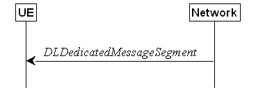
Figure 5.7.6.1-1: DL message segment transfer
The purpose of this procedure is to
transfer segments of DL DCCH messages from the network to the UE.
NOTE: The segmentation of DL DCCH message is
only applicable to RRCReconfiguration and RRCResume messages in
this release.
The network initiates the DL Dedicated
Message Segment transfer procedure whenever the encoded RRC message PDU exceeds
the maximum PDCP SDU size. The network initiates the DL Dedicated Message
Segment transfer procedure by sending the DLDedicatedMessageSegment
message.
Upon receiving DLDedicatedMessageSegment
message, the UE shall:
1> store the segment
included in rrc-MessageSegmentContainer;
1> if all segments of the message have been
received:
2> assemble the
message from the received segments and process the message according to 5.3.5.3
for the RRCReconfiguration message or 5.3.13.4 for the RRCResume
message;
2> discard all segments.
5.7.7 UL message segment transfer

Figure 5.7.7.1-1: UL message segment transfer
The purpose of this procedure is to
transfer segments of UL DCCH messages from UE to a NG-RAN in RRC_CONNECTED.
NOTE: The segmentation of UL DCCH message is
only applicable to UECapabilityInformation and MeasurementReportAppLayer
in this release.
A UE capable of UL
RRC message segmentation in RRC_CONNECTED will initiate the procedure when the
following conditions are met:
1> if the RRC message segmentation is enabled based on the field rrc-SegAllowed,
rrc-MaxCapaSegAllowed, rrc-SegAllowedSRB4
or rrc-SegAllowedSRB5 received, and
1> if the encoded RRC message
is larger than the maximum supported size of a PDCP SDU
specified in TS 38.323 [5];
Upon initiating the procedure, the UE
shall:
1> initiate transmission of the ULDedicatedMessageSegment
message as specified in 5.7.7.3;
The UE shall
segment the encoded RRC PDU based
on the maximum supported size of a PDCP SDU specified in TS 38.323 [5] and the maximum number of UL segments
according to rrc-SegAllowed or rrc-MaxCapaSegAllowed (for
segmentation of UECapabilityInformation) and rrc-SegAllowedSRB4
or rrc-SegAllowedSRB5 (for segmentation of MeasurementReportAppLayer),
if received. UE shall minimize the number of segments
and set the contents of the ULDedicatedMessageSegment
messages as follows:
1> For each new UL DCCH message, set the segmentNumber
to 0 for the first message segment and increment the segmentNumber for
each subsequent RRC message segment;
1> set rrc-MessageSegmentContainer
to include the segment of the UL DCCH message corresponding to the segmentNumber;
1> if the segment included in the rrc-MessageSegmentContainer
is the last segment of the UL DCCH message:
2> set the rrc-MessageSegmentType to lastSegment;
1> else:
2> set the rrc-MessageSegmentType to notLastSegment;
1> submit all the ULDedicatedMessageSegment
messages generated for the segmented RRC message to lower layers for
transmission in ascending order based on the segmentNumber, upon which
the procedure ends.
This procedure specifies the measurements
to be performed and stored by a UE in RRC_IDLE and RRC_INACTIVE when it has an
idle/inactive measurement configuration.
The purpose of this procedure is to update
the idle/inactive measurement configuration.
The UE initiates this procedure while T331
is running and SDT procedure is not ongoing and one of the following conditions
is met:
1> upon selecting a cell when entering RRC_IDLE
or RRC-INACTIVE from RRC_CONNECTED or RRC_INACTIVE; or
1> upon update of system information (SIB4,
or SIB11), e.g. due to intra-RAT cell (re)selection;
While in RRC_IDLE or RRC_INACTIVE, and T331
is running, the UE shall:
1> if VarMeasIdleConfig includes neither
a measIdleCarrierListEUTRA nor a measIdleCarrierListNR received
from the RRCRelease message:
2> if the UE supports idleInactiveEUTRA-MeasReport:
3> if the SIB11 includes the measIdleConfigSIB
and contains measIdleCarrierListEUTRA:
4> store or replace the measIdleCarrierListEUTRA
of measIdleConfigSIB of SIB11 within VarMeasIdleConfig;
3> else:
4> remove the measIdleCarrierListEUTRA
in VarMeasIdleConfig, if stored;
2> if the UE supports idleInactiveNR-MeasReport:
3> if SIB11 includes the measIdleConfigSIB
and contains measIdleCarrierListNR:
4> store or replace the measIdleCarrierListNR
of measIdleConfigSIB of SIB11 within VarMeasIdleConfig;
3> else:
4> remove the measIdleCarrierListNR in VarMeasIdleConfig,
if stored;
2> if SIB11 includes the measIdleConfigSIB
and contains measIdleValidityDuration:
3> store or replace the measIdleValidityDuration
of measIdleConfigSIB of SIB11 within VarEnhMeasIdleConfig;
2> else:
3> remove the measIdleValidityDuration
in VarEnhMeasIdleConfig, if stored;
1> for each entry in the measIdleCarrierListNR
within VarMeasIdleConfig that does not contain an ssb-MeasConfig
received from the RRCRelease message:
2> if there is an entry in measIdleCarrierListNR
in measIdleConfigSIB of SIB11 that has the same carrier frequency
and subcarrier spacing as the entry in the measIdleCarrierListNR within VarMeasIdleConfig
and that contains ssb-MeasConfig:
3> delete the ssb-MeasConfig of the
corresponding entry in the measIdleCarrierListNR within VarMeasIdleConfig;
3> store the SSB measurement configuration from
SIB11 into nrofSS-BlocksToAverage, absThreshSS-BlocksConsolidation,
smtc, ssb-ToMeasure, deriveSSB-IndexFromCell, and ss-RSSI-Measurement
within ssb-MeasConfig of the corresponding entry in the measIdleCarrierListNR
within VarMeasIdleConfig;
2> else if there is an entry in interFreqCarrierFreqList
of SIB4 with the same carrier frequency and subcarrier spacing as the
entry in measIdleCarrierListNR within VarMeasIdleConfig:
3> delete the ssb-MeasConfig of the
corresponding entry in the measIdleCarrierListNR within VarMeasIdleConfig;
3> store the SSB measurement configuration from
SIB4 into nrofSS-BlocksToAverage, absThreshSS-BlocksConsolidation,
smtc, ssb-ToMeasure, deriveSSB-IndexFromCell, and ss-RSSI-Measurement
within ssb-MeasConfig of the corresponding entry in the measIdleCarrierListNR
within VarMeasIdleConfig;
2> else:
3> remove the ssb-MeasConfig of the
corresponding entry in the measIdleCarrierListNR within VarMeasIdleConfig,
if stored;
1> perform measurements according to 5.7.8.2a.
The purpose of this procedure is to update
the reselection measurement configuration.
The UE initiates this procedure while SDT
procedure is not ongoing and one of the following conditions is met:
1> upon selecting a cell when entering RRC_IDLE
or RRC_INACTIVE from RRC_CONNECTED or RRC_INACTIVE; or
1> upon update of system information (SIB11),
e.g., due to intra-RAT cell (re)selection;
While in RRC_IDLE or RRC_INACTIVE, the UE
shall:
1> if VarMeasReselectionConfig does not
include measReselectionCarrierListNR received from the RRCRelease
message:
2> if the UE supports reselection measurement
reporting:
3> if SIB11 includes the measIdleConfigSIB
and contains measReselectionCarrierListNR:
4> store or replace the measReselectionCarrierListNR
of measIdleConfigSIB of SIB11 within VarMeasReselectionConfig;
3> else:
4> remove the measReselectionCarrierListNR
in VarMeasReselectionConfig, if stored;
1> if VarMeasReselectionConfig does not
include measReselectionValidityDuration received from the RRCRelease
message:
2> if SIB11 includes the measIdleConfigSIB
and contains measReselectionValidityDuration:
3> store or replace the measReselectionValidityDuration
of measIdleConfigSIB of SIB11 within VarMeasReselectionConfig;
2> else:
3> remove the measurementValidityDuration
in VarMeasReselectionConfig, if stored.
When performing measurements on NR carriers
according to this clause, the UE shall derive the cell quality as specified in
5.5.3.3 and consider the beam quality to be the value of the measurement
results of the concerned beam, where each result is averaged as described in TS
38.215 [9].
While in RRC_IDLE or RRC_INACTIVE, and T331
is running and SDT procedure is not ongoing, the UE shall:
1> perform the measurements in accordance with
the following:
2> if the VarMeasIdleConfig includes the
measIdleCarrierListEUTRA and the SIB1 contains idleModeMeasurementsEUTRA:
3> for each entry in measIdleCarrierListEUTRA
within VarMeasIdleConfig:
4> if UE supports NE-DC between the serving
carrier and the carrier frequency indicated by carrierFreqEUTRA within
the corresponding entry:
5> perform measurements in the carrier
frequency and bandwidth indicated by carrierFreqEUTRA and allowedMeasBandwidth
within the corresponding entry;
5> if the reportQuantitiesEUTRA is set
to rsrq:
6> consider RSRQ as the sorting quantity;
5> else:
6> consider RSRP as the sorting quantity;
5> if the measCellListEUTRA is included:
6> consider cells identified by each entry
within the measCellListEUTRA to be applicable for idle/inactive mode
measurement reporting;
5> else:
6> consider up to maxCellMeasIdle
strongest identified cells, according to the sorting quantity, to be applicable
for idle/inactive measurement reporting;
5> for all cells applicable for idle/inactive
measurement reporting, derive measurement results for the measurement
quantities indicated by reportQuantitiesEUTRA;
5> store the derived measurement results as
indicated by reportQuantitiesEUTRA within the measReportIdleEUTRA
in VarMeasIdleReport in decreasing order of the sorting quantity, i.e.
the best cell is included first, as follows:
6> if qualityThresholdEUTRA is
configured:
7> include the measurement results from the
cells applicable for idle/inactive measurement reporting whose RSRP/RSRQ
measurement results are above the value(s) provided in qualityThresholdEUTRA;
6> else:
7> include the measurement results from all
cells applicable for idle/inactive measurement reporting;
2> if the VarMeasIdleConfig includes the
measIdleCarrierListNR and the SIB1 contains idleModeMeasurementsNR:
3> for each entry in measIdleCarrierListNR
within VarMeasIdleConfig that contains ssb-MeasConfig:
4> if UE supports carrier aggregation or NR-DC
between serving carrier and the carrier frequency and subcarrier spacing
indicated by carrierFreq and ssbSubCarrierSpacing within the
corresponding entry:
5> perform measurements in the carrier
frequency and subcarrier spacing indicated by carrierFreq and ssbSubCarrierSpacing
within the corresponding entry;
5> if the reportQuantities is set to
rsrq:
6> consider RSRQ as the cell sorting quantity;
5> else:
6> consider RSRP as the cell sorting quantity;
5> if the measCellListNR is included:
6> consider cells identified by each entry
within the measCellListNR to be applicable for idle/inactive measurement
reporting;
5> else:
6> consider up to maxCellMeasIdle
strongest identified cells, according to the sorting quantity, to be applicable
for idle/inactive measurement reporting;
5> for all cells applicable for idle/inactive
measurement reporting, derive cell measurement results for the measurement
quantities indicated by reportQuantities;
5> store the derived cell measurement results
as indicated by reportQuantities for cells applicable for idle/inactive
measurement reporting within measResultsPerCarrierListIdleNR in the measReportIdleNR
in VarMeasIdleReport in decreasing order of the cell sorting quantity,
i.e. the best cell is included first, as follows:
6> if qualityThreshold is configured:
7> include the measurement results from the
cells applicable for idle/inactive measurement reporting whose RSRP/RSRQ
measurement results are above the value(s) provided in qualityThreshold;
6> else:
7> include the measurement results from all
cells applicable for idle/inactive measurement reporting;
5> if beamMeasConfigIdle is included in
the associated entry in measIdleCarrierListNR and if UE supports idleInactiveNR-MeasBeamReport
for the FR of the carrier frequency indicated by carrierFreq within the
associated entry, for each cell in the measurement results:
6> derive beam measurements based on SS/PBCH
block for each measurement quantity indicated in reportQuantityRS-Indexes,
as described in TS 38.215 [9];
6> if the reportQuantityRS-Indexes is
set to rsrq:
7> consider RSRQ as the beam sorting quantity;
6> else:
7> consider RSRP as the beam sorting quantity;
6> set resultsSSB-Indexes to include up
to maxNrofRS-IndexesToReport SS/PBCH block indexes in order of
decreasing beam sorting quantity as follows:
7> include the index associated to the best
beam for the sorting quantity and if absThreshSS-BlocksConsolidation is
included, the remaining beams whose sorting quantity is above absThreshSS-BlocksConsolidation;
6> if the includeBeamMeasurements is set
to true:
7> include the beam measurement results as
indicated by reportQuantityRS-Indexes;
2> if, as a result of the procedure in this clause,
the UE performs measurements in one or more carrier frequency indicated by measIdleCarrierListNR
or measIdleCarrierListEUTRA:
3> store the cell measurement results for RSRP
and RSRQ for the serving cell within measResultServingCell in the
measReportIdleNR in VarMeasIdleReport.
3> if the VarMeasIdleConfig includes the
measIdleCarrierListNR and it contains an entry with carrierFreq
set to the value of the serving frequency:
4> if beamMeasConfigIdle is included in
that entry, and if the UE supports idleInactiveNR- MeasBeamReport for
the FR of the serving cell:
5> derive beam measurements based on SS/PBCH
block for each measurement quantity indicated in reportQuantityRS-Indexes,
as described in TS 38.215 [9];
5> if the reportQuantityRS-Indexes is
set to rsrq:
6> consider RSRQ as the beam sorting quantity;
5> else:
6> consider RSRP as the beam sorting quantity;
5> set resultsSSB-Indexes to include up
to maxNrofRS-IndexesToReport SS/PBCH block indexes in order of
decreasing beam sorting quantity as follows:
6> include the index associated to the best
beam for the sorting quantity and if absThreshSS-BlocksConsolidation is
included in SIB2 of serving cell, the remaining beams whose sorting
quantity is above absThreshSS-BlocksConsolidation;
5> if the includeBeamMeasurements is set
to true:
6> include the beam measurement results as
indicated by reportQuantityRS-Indexes;
NOTE 1: How the UE performs idle/inactive
measurements is up to UE implementation as long as the requirements in TS
38.133 [14] are met for measurement reporting.
NOTE 2: The UE is not required to perform
idle/inactive measurements on a given carrier if the SSB configuration of that
carrier provided via dedicated signaling is different from the SSB
configuration broadcasted in the serving cell, if any.
NOTE 3: How the UE prioritizes which frequencies
to measure or report (in case it is configured with more frequencies than it
can measure or report) is left to UE implementation.
NOTE 4: When idleModeMeasVoiceFallback is
included in SIB5, UE may decide to measure and report idle/inactive
measurements for EUTRA carrier frequencies included in SIB5 even if it does not
support NE-DC between the serving carrier and the EUTRA carrier frequencies.
The UE shall:
1> if T331 expires or is stopped:
2> release the VarMeasIdleConfig.
NOTE: It is up to UE implementation whether
to continue idle/inactive measurements according to SIB11 and SIB4
configurations or according to E-UTRA SIB5 and E-UTRA SIB24 configurations as
specified in TS 36.331 [10] upon inter-RAT cell reselection to E-UTRA, after
T331 has expired or stopped.
The UE shall:
1> if intra-RAT cell selection or reselection
occurs while T331 is running:
2> if validityAreaList is configured in VarMeasIdleConfig:
3> if the serving frequency does not match with
the carrierFreq of an entry in the validityAreaList; or
3> if the serving
frequency matches with the carrierFreq of an entry in the validityAreaList,
the validityCellList is included in that entry,
and the physical cell identity of the serving cell does not match with any
entry in validityCellList:
4> stop timer T331;
4> perform the actions as specified in 5.7.8.3,
upon which the procedure ends.
1> else if inter-RAT cell selection or
reselection occurs while T331 is running:
2> stop timer T331;
2> perform the actions as specified in 5.7.8.3;
This procedure specifies how the mobility
history information is stored by the UE, covering RRC_IDLE, RRC_INACTIVE and
RRC_CONNECTED and released by the UE upon deregistration as specified in TS 23.502 [43].
If the UE supports storage of mobility
history information, the UE shall:
1> If the UE supports PSCell mobility history
information and upon addition of a PSCell:
2> include an entry in visitedPSCellInfoList
in variable VarMobilityHistoryReport possibly after performing the
following, if necessary:
3> if visitedPSCellInfoListReport is
available in the visitedCellInfoList in variable VarMobilityHistoryReport:
4> for the oldest PCell entry in visitedCellInfoList
including visitedPSCellInfoListReport;
5> remove the oldest entry in the visitedPSCellInfoListReport;
3> else:
4> remove the oldest entry in visitedPSCellInfoList
in variable VarMobilityHistoryReport;
2> for the included entry:
3> set the field timeSpent of the entry
according to following:
4> if this is the first PSCell entry for the
current PCell since entering the current PCell in RRC_CONNECTED:
5> include the entry as the time spent with no
PSCell since entering the current PCell in RRC_CONNECTED;
4> else:
5> include the time spent with no PSCell since
last PSCell release since entering the current PCell in RRC_CONNECTED;
1> If the UE supports PSCell mobility history
information and upon change, or release of a PSCell while being connected to
the current PCell, or upon release of a PSCell while
entering 'camped normally' state or 'any cell selection' state or 'camped on
any cell' state:
2> include an entry in visitedPSCellInfoList
of the variable VarMobilityHistoryReport possibly after performing the
following, if necessary:
3> if visitedPSCellInfoListReport is
available in the visitedCellInfoList in variable VarMobilityHistoryReport:
4> for the oldest PCell entry in visitedCellInfoList
including visitedPSCellInfoListReport;
5> remove the oldest entry in the visitedPSCellInfoListReport;
3> else:
4> remove the oldest entry in visitedPSCellInfoList
in variable VarMobilityHistoryReport;
2> for the included entry:
3> if the global
cell identity of the previous PSCell is available:
4> include the
global cell identity of that cell in the field visitedCellId of the
entry;
3> else:
4> include the
physical cell identity and carrier frequency of that cell in the field visitedCellId
of the entry;
3> if the PSCell is changed or released while
being connected to the current PCell, or if the PSCell is released while
entering 'camped normally' state in the same serving cell which was previously
the PCell:
4> set the field timeSpent of the entry
as the time spent in the previous PSCell while being connected to the current
PCell/serving cell;
3> if the PSCell is
released while entering 'any cell selection' state or
'camped on any cell' state from a suitable cell in RRC_CONNECTED state in NR or
LTE, or if the PSCell is released while entering 'camped normally' state while
previously in RRC_CONNECTED state in a PCell different from the current serving
cell:
4> set the field timeSpent of the entry
as the time spent in the previous PSCell while being connected to the previous
PCell;
1> Upon change of suitable cell, consisting of
PCell in RRC_CONNECTED (for NR or E-UTRA cell) or serving cell in RRC_INACTIVE
(for NR cell) or in RRC_IDLE (for NR or E-UTRA cell), to another NR or E-UTRA
cell, or when entering 'any cell selection' state from 'camped normally' state
in NR or LTE or when entering 'any cell selection' state or
'camped on any cell' state from a suitable cell in RRC_CONNECTED state in
NR or LTE:
NOTE: Change of suitable cell encompasses
also simultaneous change of serving cell and RRC state change.
2> include an entry in visitedCellInfoList
of the variable VarMobilityHistoryReport possibly after removing the
oldest entry, if necessary, according to following:
3> if the global cell identity of the previous
PCell/serving cell is available:
4> include the global cell identity of that
cell in the field visitedCellId of the entry;
3> else:
4> include the physical cell identity and
carrier frequency of that cell in the field visitedCellId of the entry;
3> set the field timeSpent of the entry
as the time spent in the previous PCell/serving cell;
3> if the UE supports PSCell mobility history
information and if the UE continues to be connected to the same PSCell during
the change of the PCell in RRC_CONNECTED; or
3> if the UE supports PSCell mobility history
information and if the UE changes PSCell at the same time as the change of the
PCell in RRC_CONNECTED; or
3> if the UE supports PSCell mobility history
information and if the PSCell is released at the same time as the change of the
PCell in RRC_CONNECTED:
4> include an entry
in visitedPSCellInfoList of the variable VarMobilityHistoryReport
possibly after performing the following, if necessary:
5> if visitedPSCellInfoListReport is
available in the visitedCellInfoList in variable VarMobilityHistoryReport:
6> for the oldest PCell entry in visitedCellInfoList
including visitedPSCellInfoListReport;
7> remove the oldest entry in the visitedPSCellInfoListReport;
5> else:
6> remove the oldest entry in visitedPSCellInfoList
in variable VarMobilityHistoryReport;
4> for the included
entry:
5> if the global cell identity of the PSCell (in
case the UE continues to be connected to the same PSCell) or the previous
PSCell (in case the UE changes PSCell, or in case PSCell is released) is
available:
6> include the global cell identity of that
cell in the field visitedCellId of the entry;
5> else:
6> include the physical cell identity and
carrier frequency of that cell in the field visitedCellId of the entry;
5> set the field timeSpent of the entry
as the time spent in the PSCell, while being connected to previous PCell;
3> if the UE supports PSCell mobility history
information and if the UE was not configured with a PSCell at the time of
change of PCell in RRC_CONNECTED; or
3> if the UE supports PSCell mobility history
information and if the UE was not configured with a PSCell at the time of
entering 'camped normally' state while previously in RRC_CONNECTED state in a
PCell different from the current serving cell; or
3> if the UE supports PSCell mobility history
information and if the UE was not configured with a PSCell at the time of
entering 'any cell selection' state or 'camped on any cell' state from a
suitable cell in RRC_CONNECTED state in NR or LTE:
4> include an entry in visitedPSCellInfoList
in variable VarMobilityHistoryReport after performing
the following, if necessary;
5> if visitedPSCellInfoListReport is
available in the visitedCellInfoList in variable VarMobilityHistoryReport:
6> for the oldest PCell entry in visitedCellInfoList
including visitedPSCellInfoListReport;
7> remove the oldest entry in the visitedPSCellInfoListReport;
5> else:
6> remove the oldest entry in visitedPSCellInfoList
in variable VarMobilityHistoryReport;
4> for the included entry:
5> set the field timeSpent of the entry
as the time without PSCell according to the following:
6> if the UE experienced a PSCell release since
entering the previous PCell in RRC_CONNECTED:
7> include the time spent with no PSCell since
last PSCell release since entering the previous PCell in RRC_CONNECTED;
6> else:
7> include the time spent with no PSCell since
entering the previous PCell in RRC_CONNECTED;
3> if the UE supports PSCell mobility history
information and if visitedPSCellInfoList exists in VarMobilityHistoryReport:
4> include visitedPSCellInfoList
in VarMobilityHistoryReport in the visitedPSCellInfoListReport
within the entry of the visitedCellInfoList associated to the latest
PCell entry;
4> remove visitedPSCellInfoList
from the variable VarMobilityHistoryReport;
1> if the UE supports PSCell mobility history
information and upon entering 'camped normally' state in NR (in RRC_IDLE or
RRC_INACTIVE) or E-UTRA (in RRC_IDLE) while previously in RRC_CONNECTED state
NR or LTE in the same serving cell which was previously the PCell while not
connected to a PSCell:
2> include an entry in visitedPSCellInfoList
in variable VarMobilityHistoryReport after performing the following, if
necessary;
3> if visitedPSCellInfoListReport is
available in the visitedCellInfoList in variable VarMobilityHistoryReport:
4> for the oldest PCell entry in visitedCellInfoList
including visitedPSCellInfoListReport;
5> remove the oldest entry in the visitedPSCellInfoListReport;
3> else:
4> remove the oldest entry in visitedPSCellInfoList
in variable VarMobilityHistoryReport;
2> for the included entry:
3> set the field timeSpent of the entry
as the time without PSCell according to the following:
4> if the UE experienced a PSCell release since
entering the current serving cell in RRC_CONNECTED:
5> include the time spent with no PSCell since
last PSCell release after entering the current serving cell in RRC_CONNECTED;
4> else:
5> include the time spent with no PSCell since
entering the current serving cell in RRC_CONNECTED;
1> upon entering 'camped normally' state in NR
(in RRC_IDLE or RRC_INACTIVE) or E-UTRA (in RRC_IDLE) while previously in 'any
cell selection' state or 'camped on any cell' state in NR or LTE:
2> include an entry in visitedCellInfoList
in variable VarMobilityHistoryReport possibly after removing the oldest
entry, if necessary, according to following:
3> set the field timeSpent of the entry
as the time spent in 'any cell selection' state and/or 'camped on any cell'
state in NR or LTE.
If the UE supports storage of mobility
history information, the UE shall:
1> if stored, discard the mobility history
information, i.e. release the UE variable VarMobilityHistoryReport upon
deregistration from the network as specified in TS
23.502 [43].
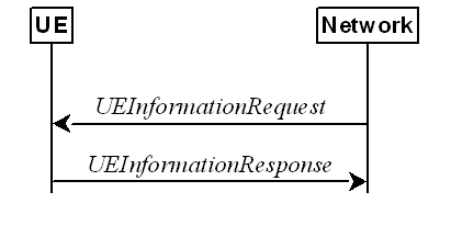
Figure 5.7.10.1-1: UE information procedure
The UE information procedure is used by the
network to request the UE to report information.
The network initiates the procedure by
sending the UEInformationRequest message. The network should
initiate this procedure only after successful security activation.
Upon receiving the UEInformationRequest
message, the UE shall, only after successful security activation:
1> if the idleModeMeasurementReq is
included in the UEInformationRequest and the UE has stored VarMeasIdleReport
that contains measurement information concerning cells other than the
PCell:
2> if validatedMeasurementsReq is
included in the UEInformationRequest and measIdleValidityDuration
is included in VarEnhMeasIdleConfig;
3> set the measResultIdleEUTRA
in the UEInformationResponse message to the value of measReportIdleEUTRA
in the VarMeasIdleReport for any valid measurement results, if
available, and set validityStatus to the value of measIdleValidityDuration
in VarEnhMeasIdleConfig for each reported measurement;
3> set the measResultIdleNR in the
UEInformationResponse message to the value of measReportIdleNR in the VarMeasIdleReport
for any valid measurement results, if available, and set validityStatus to
the value of measIdleValidityDuration in VarEnhMeasIdleConfig for
each reported measurement;
3> discard the VarMeasIdleReport upon
successful delivery of the UEInformationResponse message confirmed by
lower layers;
2> else:
3> set the measResultIdleEUTRA in the UEInformationResponse
message to the value of measReportIdleEUTRA in the VarMeasIdleReport,
if available;
3> set the measResultIdleNR in the UEInformationResponse
message to the value of measReportIdleNR in the VarMeasIdleReport,
if available;
3> discard the VarMeasIdleReport upon
successful delivery of the UEInformationResponse message confirmed by
lower layers;
1> if the reselectionMeasurementReq is
included in the UEInformationRequest:
2> if validatedMeasurementsReq is
included in the UEInformationRequest and measReselectionValidityDuration
is included in VarMeasReselectionConfig;
3> if measReselectionCarrierListNR is
present in VarMeasReselectionConfig:
4> set the measResultReselectionNR in
the UEInformationResponse message the valid NR measurement results, if available for any frequency listed in measReselectionCarrierListNR
in VarMeasReselectionConfig and set validityStatus to the value
of measIdleValidityDuration in VarMeasReselectionConfig for
each reported measurement;
3> else:
4> set the measResultReselectionNR in
the UEInformationResponse message to any valid NR measurement results,
if available, and set validityStatus to the value of measIdleValidityDuration
in VarMeasReselectionConfig;
2> else:
3> if measReselectionCarrierListNR is
present in VarMeasReselectionConfig:
4> set the measResultReselectionNR in
the UEInformationResponse message the NR measurement results, if available for any frequency listed in measReselectionCarrierListNR
in VarMeasReselectionConfig;
3> else:
4> set the measResultReselectionNR in
the UEInformationResponse message to any NR measurement results, if
available;
1> if the logMeasReportReq is present and if the RPLMN is
included in plmn-IdentityList stored in VarLogMeasReport, or if
the current registered SNPN identity is included in snpn-ConfigID-List
stored in VarLogMeasReport:
2> if VarLogMeasReport includes one or more logged measurement entries, set the contents of the logMeasReport in
the UEInformationResponse message as follows:
3> include the absoluteTimeStamp and set
it to the value of absoluteTimeInfo in the VarLogMeasReport;
3> include
the traceReference and set it to the value of traceReference in
the VarLogMeasReport;
3> include the traceRecordingSessionRef
and set it to the value of traceRecordingSessionRef in the VarLogMeasReport;
3> include the tce-Id and set it to the
value of tce-Id in the VarLogMeasReport;
3> include the logMeasInfoList
and set it to include one or
more entries from the VarLogMeasReport starting from the entries logged first, and
for each entry of the logMeasInfoList that is included, include all information stored in the corresponding logMeasInfoList entry in VarLogMeasReport;
3> if the VarLogMeasReport includes one
or more additional logged measurement entries that are not included in the logMeasInfoList
within the UEInformationResponse message:
4> include the logMeasAvailable;
4> if bt-LocationInfo is included in locationInfo
of one or more of the additional logged measurement entries in VarLogMeasReport
that are not included in the logMeasInfoList within the UEInformationResponse
message:
5> include the logMeasAvailableBT;
4> if wlan-LocationInfo is included in locationInfo
of one or more of the additional logged measurement entries in VarLogMeasReport
that are not included in the logMeasInfoList within the UEInformationResponse
message:
5> include the logMeasAvailableWLAN;
1> if ra-ReportReq is set to true
and the UE has random access related information available in VarRA-Report
and if the RPLMN is included in plmn-IdentityList stored in VarRA-Report;
or
1> if ra-ReportReq is set to true
and the UE has random access related information available in VarRA-Report
and if the registered SNPN identity is included in snpn-IdentityList
stored in VarRA-Report:
2> set the ra-ReportList in the UEInformationResponse
message to the value of ra-ReportList in VarRA-Report;
2> discard the ra-ReportList from VarRA-Report
upon successful delivery of the UEInformationResponse message confirmed
by lower layers;
1> if rlf-ReportReq is set to true:
2> if the UE has radio link failure information
or handover failure information available in VarRLF-Report and if the
RPLMN is included in plmn-IdentityList stored in VarRLF-Report;
or
2> if the UE has radio link failure information
or handover failure information available in VarRLF-Report and if the
current registered SNPN identity is included in snpn-IdentityList stored in VarRLF-Report:
3> set timeSinceFailure in VarRLF-Report
to the time that elapsed since the last radio link failure or handover failure
in NR;
3> set the rlf-Report in the UEInformationResponse
message to the value of rlf-Report in VarRLF-Report;
3> discard the rlf-Report from VarRLF-Report
upon successful delivery of the UEInformationResponse message confirmed
by lower layers;
2> else if the UE is capable of cross-RAT RLF
reporting as defined in TS 38.306 [26] and has radio link failure information
or handover failure information available in VarRLF-Report of TS 36.331
[10] and if the RPLMN is included in plmn-IdentityList stored in VarRLF-Report
of TS 36.331 [10]:
3> set timeSinceFailure in VarRLF-Report
of TS 36.331 [10] to the time that elapsed since the last radio link failure or
handover failure in EUTRA;
3> set failedPCellId-EUTRA in the rlf-Report
in the UEInformationResponse message to indicate the PCell in which RLF
was detected or the source PCell of the failed handover in the VarRLF-Report
of TS 36.331 [10];
3> set the measResult-RLF-Report-EUTRA
in the rlf-Report in the UEInformationResponse message to the
value of rlf-Report in VarRLF-Report of TS 36.331 [10];
3> discard the rlf-Report from VarRLF-Report
of TS 36.331 [10] upon successful delivery of the UEInformationResponse
message confirmed by lower layers;
1> if connEstFailReportReq is set to true
and the UE has connection establishment failure or connection resume failure
information in VarConnEstFailReport or VarConnEstFailReportList and
if the RPLMN is equal to plmn-Identity stored in VarConnEstFailReport
or in at least one of the entries of
VarConnEstFailReportList:
1> if connEstFailReportReq
is set to true and if the UE has connection
establishment failure information or connection resume failure information
available in VarConnEstFailReport or VarConnEstFailReportList and
if the registered SNPN identity is equal to snpn-Identity in networkIdentity
stored in VarConnEstFailReport or any entry
of VarConnEstFailReportList:
2> set timeSinceFailure in VarConnEstFailReport
to the time that elapsed since the last connection establishment failure or
connection resume failure in NR;
2> set the connEstFailReport in the UEInformationResponse
message to the value of connEstFailReport in VarConnEstFailReport;
2> if the UE supports
multiple CEF report:
3> for each connEstFailReport in the connEstFailReportList
in VarConnEstFailReportList:
4> set timeSinceFailure to the time that
elapsed since the associated connection establishment failure or connection
resume failure in NR;
2> for each connEstFailReport in the connEstFailReportList
in the UEInformationResponse message, set the value to the value of connEstFailReport
in VarConnEstFailReport in VarConnEstFailReportList;
2> discard the connEstFailReport from VarConnEstFailReport
and VarConnEstFailReportList upon successful delivery of the UEInformationResponse
message confirmed by lower layers;
1> if the mobilityHistoryReportReq is
set to true:
2> include the mobilityHistoryReport and
set it to include visitedCellInfoList from VarMobilityHistoryReport;
2> include in the mobilityHistoryReport
an entry for the current PCell, possibly after removing the oldest entry if
required, and set its fields as follows:
3> set visitedCellId to the global cell
identity or the physical cell identity and carrier frequency of the current PCell:
3> set field timeSpent to the time spent
in the current PCell;
3> if the UE supports PSCell mobility history
information and if visitedPSCellInfoList is present in VarMobilityHistoryReport:
4> for the newest entry of the PCell in the mobilityHistoryReport,
include visitedPSCellInfoList from VarMobilityHistoryReport;
4> if the UE is configured with a PSCell:
5> for the newest entry of the PCell in the mobilityHistoryReport,
include the current PSCell information in the visitedPSCellInfoListReport,
possibly after removing the oldest PSCell entry of a PCell in the mobilityHistoryReport,
if required, and set its fields as follows:
6> set visitedCellId to the global cell
identity or the physical cell identity and carrier frequency of the current
PSCell:
6> set field timeSpent to the time spent
in the current PSCell while being connected to the current PCell;
4> else:
5> for the newest entry of the PCell in the mobilityHistoryReport,
include a new entry in the visitedPSCellInfoListReport, possibly after
removing the oldest PSCell entry of a PCell in the mobilityHistoryReport,
if required, and set its fields as follows:
6> set field timeSpent to the time spent
without PSCell in the current PCell since last PSCell release since connected
to the current PCell in RRC_CONNECTED;
3> else if the UE supports PSCell mobility
history information:
4> if the UE is configured with a PSCell:
5> for the newest entry of the PCell in the mobilityHistoryReport,
include the current PSCell information in the visitedPSCellInfoListReport, possibly
after removing the oldest PSCell entry of a PCell in the mobilityHistoryReport,
if required, and set its fields as follows:
6> set visitedCellId to the global cell
identity or the physical cell identity and carrier frequency of the current
PSCell:
6> set field timeSpent to the time spent
in the current PSCell while being connected to the current PCell;
4> else:
5> for the newest entry of the PCell in the mobilityHistoryReport,
include a new entry in the visitedPSCellInfoListReport, possibly after
removing the oldest PSCell entry of a PCell in the mobilityHistoryReport,
if required, and set its fields as follows:
6> set field timeSpent to the time spent
without PSCell in the current PCell since connected to the current PCell in
RRC_CONNECTED;
1> if the successHO-ReportReq is set to true
and if the UE has successful handover related information available in VarSuccessHO-Report
and if the RPLMN is included in the plmn-IdentityList stored in VarSuccessHO-Report;
or
1> if the successHO-ReportReq is set to true
and if the UE has successful handover related information available in VarSuccessHO-Report
and if the current registered SNPN identity is included
in snpn-IdentityList if stored in the VarSuccessHO-Report:
2> if the successHO-Report in the VarSuccessHO-Report
concerns a DAPS handover and if a PDCP PDU has been received from the source
cell of the concerned HO and a non-duplicated PDCP PDU has been received from
the target cell of the concerned HO:
3> set upInterruptionTimeAtHO in VarSuccessHO-Report
to include the time elapsed between the time of arrival of the last PDCP PDU
received from the source cell of the concerned handover and the time of arrival
of the first non-duplicate PDCP PDU received from the target cell of the
concerned handover, as measured at the time of arrival of the first
non-duplicate PDCP PDU received from the target cell;
2> if the successHO-Report in the VarSuccessHO-Report
concerns a mobilityFromNRCommand:
3> set timeSinceSHR in VarSuccessHO-Report
to the time that elapsed since the successful handover report determination as
specified in 5.7.10.6;
2> set the successHO-Report in the UEInformationResponse
message to the value of successHO-Report in the VarSuccessHO-Report,
if available;
2> discard the VarSuccessHO-Report upon
successful delivery of the UEInformationResponse message confirmed by
lower layers;
1> if the successPSCell-ReportReq is set
to true and if the UE has successful PSCell
change or addition information available in VarSuccessPSCell-Report
and if the RPLMN is included in plmn-IdentityList stored in VarSuccessPSCell-Report;
or
1> if the successPSCell-ReportReq is set
to true and if the UE has successful PSCell
change or addition information available in VarSuccessPSCell-Report
and if the current registered SNPN identity is included
in snpn-IdentityList if stored in the VarSuccessPSCell-Report:
2> set the successPSCell-Report in the UEInformationResponse
message to the value of successPSCell-Report in the VarSuccessPSCell-Report;
2> discard the VarSuccessPSCell-Report
upon successful delivery of the UEInformationResponse message confirmed
by lower layers;
1> if the coarseLocationRequest is set
to true:
2> include coarseLocationInfo, if
available;
1> if the flightPathInfoReq is included
in the UEInformationRequest and the UE has (updated) flight path
information available, set the flightPathInfoReport in the UEInformationResponse
message as follows:
2> include the list of up to maxWayPointNumber
waypoints, if any, along the flight path;
2> if the includeTimeStamp is set to true,
for each included waypoint:
3> if available, set the field timestamp
to the time when UE intends to arrive at the waypoint;
1> if the logMeasReport is included in
the UEInformationResponse:
2> submit the UEInformationResponse
message to lower layers for transmission via SRB2;
2> discard the logged measurement entries
included in the logMeasInfoList from VarLogMeasReport upon
successful delivery of the UEInformationResponse message confirmed by
lower layers;
1> else:
2> submit the UEInformationResponse
message to lower layers for transmission via SRB1.
Upon successfully performing random-access procedure initialized with 4-step or 2-step RA type, or upon failed or successfully completed on-demand system
information acquisition procedure in RRC_IDLE or RRC_INACTIVE state, or upon
failed or successfully completed RA-SDT operation as specified in clause
5.3.13.5, the UE shall:
1> if the RPLMN or the PLMN selected by upper
layers (see TS24.501 [23]) from the PLMN(s) included in the plmn-IdentityList
in SIB1 is not included in plmn-IdentityList stored in a
non-empty VarRA-Report; or
1> if the registered SNPN identity or the SNPN identity
selected by upper layers (see TS24.501 [23]) from the list of SNPN(s) included
in the NPN-IdentityInfoList in SIB1is not included in snpn-IdentityList stored in
a non-empty VarRA-Report:
2> clear the information included in VarRA-Report;
1> if the UE is not in SNPN access mode and if
the number of RA-Report entries stored in the ra-ReportList in VarRA-Report is
less than maxRAReport:
2> if the number of PLMN entries in plmn-IdentityList
in identityList stored in VarRA-Report is less than maxPLMN;
or
2> if the number of
PLMN entries in plmn-IdentityList in identityList stored in VarRA-Report
is equal to maxPLMN and the list of EPLMNs is subset of or equal to
the plmn-IdentityList stored in VarRA-Report:
3> append the following
contents associated to the random-access procedure as a new entry in the VarRA-Report:
4> if the list of EPLMNs has been stored by the
UE:
5> set the plmn-IdentityList
to include the list of EPLMNs stored by the UE (i.e. includes the RPLMN)
without exceeding the limit of maxPLMN;
4> else:
5> set the plmn-Identity, in plmn-IdentityList,
to the PLMN selected by upper layers (see TS 24.501 [23]) from the PLMN(s)
included in the plmn-IdentityInfoList in SIB1;
4> set the cellId to the global cell
identity and the tracking area code, if available, otherwise to the physical
cell identity and carrier frequency of the cell in which the corresponding
random-access preamble was transmitted;
4> if the UE supports spCell ID indication:
5> if the corresponding random-access procedure
was performed on an SCell of MCG:
6> set the spCellId
to the global cell identity of the PCell;
5> if the corresponding random-access procedure
was performed on an SCell of SCG:
6> set the spCellId to the global
cell identity of the PSCell, if available, otherwise, set the spCellId
to the global cell identity of the PCell;
5> if the corresponding random-access procedure
was performed on PSCell:
6> if the cellId
is not set to the global cell identity of the PSCell, set the spCellId
to the global cell identity of the PCell;
4> if the random-access procedure is initiated
for SDT and the SDT transmission was failed as defined in TS 38.300 [2]:
5> include the sdt-Failed;
4> set the raPurpose to include the purpose of triggering the
random-access procedure;
4> set the ra-InformationCommon as specified in clause
5.7.10.5.
1> if the UE is in SNPN access mode and if the
number of RA-Report entries stored in the ra-ReportList in VarRA-Report
is less than maxRAReport:
2> if the number of SNPN identity entries in
snpn-IdentityList in identityList stored in VarRA-Report is
less than maxNPN; or
2> if the number of
SNPN identity entries in snpn-IdentityList in identityList stored
in VarRA-Report is equal to maxNPN and the list of equivalent
SNPN(s) is subset of or equal to the snpn-IdentityList stored in VarRA-Report:
3> append the following contents associated to
the random-access procedure as a new entry in the VarRA-Report:
4> if the list of equivalent SNPN(s) has been
stored by the UE:
5> set the snpn-IdentityList
to include the list of equivalent SNPN(s) stored by the UE (i.e. includes
the registered SNPN identity) without exceeding the limit of maxNPN;
4> else:
5> set the snpn-Identity, in snpn-IdentityList,
to the SNPN identity selected by upper layers (see TS 24.501 [23]) from the
SNPN identities included in the NPN-IdentityInfoList in SIB1;
4> set the cellId to the global cell
identity and the tracking area code, if available, otherwise to the physical
cell identity and carrier frequency of the cell in which the corresponding
random-access preamble was transmitted;
4> if the UE supports spCell ID indication:
5> if the corresponding random-access procedure
was performed on an SCell of MCG:
6> set the spCellId
to the global cell identity of the PCell;
5> if the corresponding random-access procedure
was performed on an SCell of SCG:
6> set the spCellId to the global
cell identity of the PSCell, if available, otherwise, set the spCellId
to the global cell identity of the PCell;
5> if the corresponding random-access procedure
was performed on PSCell:
6> if the cellId
is not set to the global cell identity of the PSCell, set the spCellId
to the global cell identity of the PCell;
4> if the random-access procedure is initiated
for SDT and the SDT transmission was failed as defined in TS 38.300 [2]:
5> include the sdt-Failed;
4> set the raPurpose
to include the purpose of triggering the random-access procedure;
4> set the
ra-InformationCommon as specified in clause
5.7.10.5.
The UE may discard the random access report
information, i.e. release the UE variable VarRA-Report, 48 hours after
the last successful random access procedure or the failed or successfully
completed on-demand system information acquisition procedure or the failed or
successfully completed RA-SDT procedure related information is added to the VarRA-Report.
NOTE 1: Void.
5.7.10.5 RA
information determination
The UE shall, for the last successfully completed or last failed random-access procedure, set
the content in ra-InformationCommon as follows:
1> set the absoluteFrequencyPointA to indicate the absolute
frequency of the reference resource block associated to the random-access
resources used in the random-access procedure;
1> set the locationAndBandwidth and subcarrierSpacing
associated to the UL BWP of the random-access resources
used in the random-access procedure;
1> if contention based random-access resources
are used in the random-access procedure:
2> set the msgA-RO-FrequencyStart and msgA-RO-FDM and msgA-SubcarrierSpacing associated
to the 2 step random- access resources if used in the
random-access procedure;
2> if msgA-SubcarrierSpacing associated to the 2 step random-access resources used in the
random-access procedure is available:
3> set the msgA-SubcarrierSpacing
associated to the 2 step random-access resources used in the random-access procedure;
2> else if only 2 step
random-access resources are available in the UL BWP used in the random-access
procedure:
3> set the msgA-SCS-From-prach-ConfigurationIndex
to the subcarrier spacing as derived from the msgA-PRACH-ConfigurationIndex used in the 2-step random-access procedure;
2> else:
3> set the msg1-SubcarrierSpacing associated to the
4 step random-access resources used in the
random-access procedure;
2> set the msg1-FrequencyStart
associated to the 4 step random-access resources if used
in the random-access procedure, and if its value is different from the value of
msgA-RO-FrequencyStart
if it is included in the ra-InformationCommon;
2> set the msg1-FDM associated to the 4
step random-access resources if used in the
random-access procedure, and if its value is different from the value of msgA-RO-FDM if it is included in the ra-InformationCommon;
2> if msg1-SubcarrierSpacing associated to the 4 step random-access resources used in the
random-access procedure is available, and if its value is different from the
value of msgA-SubcarrierSpacing if it is included in the ra-InformationCommon:
3> set the msg1-SubcarrierSpacing
associated to the 4 step random-access resources used in the random-access procedure;
2> else:
3> set the msg1-SCS-From-prach-ConfigurationIndex
to the subcarrier spacing as derived from the prach-ConfigurationIndex used in the 4-step random-access procedure, and if its value is
different from the value of msgA-SCS-From-prach-ConfigurationIndex if it is included in the ra-InformationCommon;
1> if contention free random-access resources
are used in the random-access procedure:
2> set the msg1-FrequencyStartCFRA
and msg1-FDMCFRA associated to the 4 step random-access resources if used in the random-access procedure;
2> if msg1-SubcarrierSpacing associated to the 4 step random-access resources used in the
random-access procedure is available:
3> set the msg1-SubcarrierSpacingCFRA
associated to the 4 step random-access resources used in the random-access procedure;
2> else:
3> set the msg1-SCS-From-prach-ConfigurationIndexCFRA
to the subcarrier spacing as derived from the prach-ConfigurationIndex used in the 4 step random-access
procedure;
2> set the msgA-RO-FrequencyStartCFRA
and msgA-RO-FDMCFRA associated to the 2 step contention free random access
resources if used in the random-access procedure;
2> set the msgA-MCS, the nrofPRBs-PerMsgA-PO,
the msgA-PUSCH-TimeDomainAllocation, the frequencyStartMsgA-PUSCH,
the nrofMsgA-PO-FDM associated to the 2 step random-access resources if used in the random-access procedure;
2> if msgA-SubcarrierSpacing associated to the 2 step random-access resources used in the
random-access procedure is available:
3> set the msgA-SubcarrierSpacing
associated to the 2 step random-access resources used in the random-access procedure;
2> else if only 2 step random-access resources
are available in the UL BWP used in the random-access procedure:
3> set the msgA-SCS-From-prach-ConfigurationIndex
to the subcarrier spacing as derived from the msgA-PRACH-ConfigurationIndex used in the 2-step random-access procedure;
2> else:
3> set the msg1-SubcarrierSpacing associated to the
4 step random-access resources used in the
random-access procedure;
1> if the random access
procedure is initialized with RA_TYPE set to 2-stepRA as described in TS 38.321 [3]:
2> set the dlPathlossRSRP to the measeured RSRP of the DL pathloss reference
obtained at the time of RA_Type selection stage of the initialization of
the RA procedure as captured in TS 38.321 [3];
2> if the configuration for the random access msgA-TransMax
was configured in RACH-ConfigDedicated for this random access procedure,
and raPurpose is set to reconfigurationWithSync:
3> set msgA-TransMax
to the value of msgA-TransMax in RACH-ConfigDedicated;
2> else if msgA-TransMax was configured
in RACH-ConfigCommonTwoStepRA:
3> set msgA-TransMax
to the value of msgA-TransMax in RACH-ConfigCommonTwoStepRA;
2> set the msgA-PUSCH-PayloadSize to the
size of the overall payload available
in the UE buffer at the time of initiating the 2 step RA procedure;
1> if the purpose of the random access
procedure is to request on-demand system information (i.e., if the raPurpose
is set to requestForOtherSI or msg3RequestForOtherSI):
2> set the intendedSIBs
to indicate the SIB(s) the UE wanted to receive as a result of the SI request;
2> set the ssbsForSI-Acquisition
to indicate the SSB(s) used to receive the SI message;
2> if the on-demand
system information acquisition was successful:
3> set the onDemandSISuccess to true;
1> if one or more of the features including
RedCap and/or Slicing and/or SDT and/or MSG3 repetitions and/or MSG1
repetitions and/or eRedCap are applicable for this random-access procedure as
specified in clause 5.1.1b of TS 38.321[3]:
2> set the triggeredFeatureCombination
to indicate all the features triggering this random-access procedure as
below:
3> if this random-access procedure is triggered
by RedCap, include redCap;
3> if this random-access procedure is triggered
by SDT, include smallData;
3> if this random-access procedure is triggered
by Msg3 repetitions, include msg3-Repetitions;
3> if this random-access procedure is triggered
by Msg1 repetitions, include msg1-Repetitions;
3> if this random-access procedure is triggered
by eRedCap, include eRedCap;
3> if this random-access procedure is triggered
by slicing, set nsag to the NSAG-ID(s) applied in the random-access
procedure and set the triggered-S-NSSAI-List to include all the S-NSSAI(s)
associated to the slices triggering the access attempt in the random-access
procedure;
2> if the value of used feature or combination
of features is different from the triggeredFeatureCombination:
3> set the usedFeatureCombination to
indicate one or more features of FeatureCombination associated to the
random-access resource used in the random-access procedure as below:
4> if RedCap is part of the used FeatureCombination,
include redCap;
4> if SDT is part of the used FeatureCombination,
include smallData;
4> if Msg3 repetitions is part of the used FeatureCombination,
include msg3-Repetitions;
4> if Msg1 repetitions is part of the used FeatureCombination,
include msg1-Repetitions;
4> if eRedCap is part of the used FeatureCombination,
include eRedCap;
4> if NSAG(s) is part of the used FeatureCombination,
set nsag to include the NSAG-ID(s) configured for the used
FeatureCombination;
2> set the startPreambleForThisPartition to the value of startPreambleForThisPartition in FeatureCombinationPreambles associated to the used
FeatureCombination;
2> set the numberOfPreamblesPerSSB-ForThisPartition to the value of numberOfPreamblesPerSSB-ForThisPartition in FeatureCombinationPreambles associated to the used
FeatureCombination;
1> set the parameters associated to the
successive random-access attempts associated to the selected beam in the perRAInfoList
as follows:
2> if the random-access resource used is
associated to a SS/PBCH block, set the associated random-access parameters for
the successive random-access attempts associated to the same SS/PBCH block for
one or more random-access attempts as follows:
3> set the ssb-Index to include the
SS/PBCH block index associated to the used random-access resource;
3> set the numberOfPreamblesSentOnSSB
to indicate the number of successive random-access attempts associated to the
SS/PBCH block;
3> if all preamble
transmissions for the successive random-access attempts
associated to this SS/PBCH block were blocked by LBT:
4> include allPreamblesBlocked;
3> else:
4> if LBT failure indication was received from
lower layers for the last random-access preamble transmission attempt in the
SS/PBCH block associated to the ssb-Index, before changing the SS/PBCH
block for random access preamble transmission:
5> include lbt-Detected;
3> for each random-access attempt performed on
the random-access resource, except the random-access attempts for which LBT failure indication was received from lower layers, include the following parameters in the chronological order of the
random-access attempt:
4> if the random-access attempt is performed on
the contention based random-access resource and if raPurpose is not
equal to 'requestForOtherSI', include contentionDetected as
follows:
5> if contention resolution was not successful
as specified in TS 38.321 [6] for the transmitted preamble:
6> set the contentionDetected to true;
5> else:
6> set the contentionDetected to false;
4> if the random access attempt is a 2-step
random access attempt:
5> if fallback from 2-step random access to
4-step random access occurred during the random access attempt:
6> set fallbackToFourStepRA to true;
4> if the random-access attempt is performed on
the contention based random-access resource; or
4> if the random-access attempt is performed on
the contention free random-access resource and if the random-access procedure
was initiated due to the PDCCH ordering:
5> if the random access attempt is a 4-step
random access attempt and the SS/PBCH block RSRP of the SS/PBCH block
corresponding to the random-access resource used in the random-access attempt
is above rsrp-ThresholdSSB; or
5> if the random access attempt is a 2-step
random access attempt and the SS/PBCH block RSRP of the SS/PBCH block
corresponding to the random-access resource used in the random-access attempt
is above msgA-RSRP-ThresholdSSB:
6> set the dlRSRPAboveThreshold to true;
5> else:
6> set the dlRSRPAboveThreshold to false;
2> else if the random-access resource used is
associated to a CSI-RS, set the associated random-access parameters for the
successive random-access attempts associated to the same CSI-RS for one or more
random-access attempts as follows:
3> set the csi-RS-Index to include the
CSI-RS index associated to the used random-access resource;
3> set the numberOfPreamblesSentOnCSI-RS
to indicate the number of successive random-access attempts associated to the
CSI-RS;
3> if all preamble
transmissions for the successive random-access attempts
associated to this CSI-RS were blocked by LBT:
4> include allPreamblesBlocked;
3> else:
4> if LBT failure indication was received from
lower layers for the last random-access preamble transmission attempt in the
CSI-RS associated to the csi-RS-Index, before changing the CSI-RS for
random access preamble transmission:
5> include lbt-Detected;
1> if at least one LBT failure indication has been received from lower
layers during the random-access procedure:
2> set the numberOfLBT-Failures to indicate the total number of random-access attempts for which
LBT failure indications have been received from lower layers in the
random-access procedure.
The UE shall, for all
the BWPs in which consistent LBT failures are triggered and not cancelled (according
to TS 38.321 [3]) prior to successful RA completion or prior to RLF/HOF, set the below parameters in attemptedBWP-InfoList in the chronological order of BWP selection:
1> set the locationAndBandwidth and subcarrierSpacing
associated to the UL BWP.
NOTE 1: Void.
NOTE 2: If allPreamblesBlocked is included, it is left to UE implementation how to set the numberOfPreamblesSentOnSSB-r16, numberOfPreamblesSentOnCSI-RS-r16 and
the perRAAttemptInfoList-r16.
The UE shall for the PCell:
1> if the procedure is triggered due to
successful completion of reconfiguration with sync, and if the ratio between
the value of the elapsed time of the timer T304 and the configured value of the
timer T304, included in the last applied RRCReconfiguration message
including the reconfigurationWithSync, is greater than thresholdPercentageT304
if included in the successHO-Config received before executing the last
reconfiguration with sync; or
1> if the procedure is triggered due to
successful completion of reconfiguration with sync, and if the ratio between
the value of the elapsed time of the timer T310 and the configured value of the
timer T310, configured while the UE was connected to the source PCell before
executing the last reconfiguration with sync, is greater than thresholdPercentageT310
included in the successHO-Config if configured by the source PCell
before executing the last reconfiguration with sync; or
1> if the procedure is triggered due to
successful completion of reconfiguration with sync, and if the T312 associated
to the measurement identity of the target cell was running at the time of
initiating the execution of the reconfiguration with sync procedure and if the
ratio between the value of the elapsed time of the timer T312 and the configured
value of the timer T312, configured while the UE was connected to the source
PCell before executing the last reconfiguration with sync, is greater than thresholdPercentageT312
included in the successHO-Config if configured by the source PCell
before executing the last reconfiguration with sync; or
1> if the procedure is triggered due to
successful completion of reconfiguration with sync, and if sourceDAPS-FailureReporting
is included in the successHO-Config before executing the last
reconfiguration with sync and is set to true and if the last executed
handover was a DAPS handover and if an RLF occurred at the source PCell during
the DAPS handover while T304 was running; or:
1> if the procedure is triggered due to
successful completion of Mobility from NR to E-UTRA, and if the ratio between the value of the elapsed time of the timer
T310 and the configured value of the timer T310, configured while the UE was
connected to the source PCell before executing the last Mobility from NR to
E-UTRA, is greater than thresholdPercentageT310 included in the successHO-Config
if configured by the source PCell before executing the last Mobility from NR to
E-UTRA; or
1> if the procedure is triggered due to
successful completion of Mobility from NR to E-UTRA, and if the T312 associated
to the measurement identity of the target cell was running at the time of
initiating the execution of the Mobility from NR to E-UTRA and if the ratio
between the value of the elapsed time of the timer T312 and the configured
value of the timer T312, configured while the UE was connected to the source
PCell before executing the last Mobility from NR to E-UTRA, is greater than thresholdPercentageT312
included in the successHO-Config if configured by the source PCell
before executing the last Mobility from NR to E-UTRA:
2> store the successful handover information in
VarSuccessHO-Report and determine the content in VarSuccessHO-Report as follows:
3> clear the information included in VarSuccessHO-Report,
if any;
3> if the UE is not in SNPN access mode, set
the plmn-IdentityList to include the list of EPLMNs stored by the UE
(i.e., includes the RPLMN);
3> else if the UE is in SNPN access mode, set
the snpn-IdentityList to include the list of equivalent SNPNs stored by
the UE (i.e., including the registered SNPN identity), if available;
3> for intra-NR handover, set the c-RNTI to
the C-RNTI assigned by the target PCell of the handover;
3> if the procedure is triggered due to
successful completion of reconfiguration with sync, for the source PCell in which the last RRCReconfiguration message including reconfigurationWithSync was applied; or
3> if the procedure is triggered due to
successful completion of Mobility from NR to E-UTRA, for the source PCell in which the last MobilityFromNRCommand concerning an
inter-RAT handover from NR to E-UTRA was applied:
4> set the sourcePCellID in sourceCellInfo
to the global cell identity and tracking area code, if available, of the source
PCell;
4> set the sourceCellMeas in sourceCellInfo
to include the cell level RSRP, RSRQ and the available SINR, of the source PCell based on the available SSB and
CSI-RS measurements collected up to the moment the UE sends RRCReconfigurationComplete
message if the procedure is triggered due to successful completion of
reconfiguration with sync, or up to the moment the UE sends the EUTRA RRCConnectionReconfigurationComplete message
if the procedure is triggered due to successful completion of Mobility from NR
to E-UTRA;
4> set the rsIndexResults
in sourceCellMeas to include all the available SSB and CSI-RS
measurement quantities of the source PCell collected up to the moment the UE
sends RRCReconfigurationComplete message if the procedure is triggered
due to successful completion of reconfiguration with sync, or up to the moment the UE sends the EUTRA RRCConnectionReconfigurationComplete
message if the procedure is triggered due to successful completion of Mobility
from NR to E-UTRA;
4> if the last executed handover was a DAPS
handover and if an RLF occurred at the source PCell during the DAPS handover
while T304 was running:
5> set the rlf-InSourceDAPS in sourceCellInfo to true;
3> if the procedure is triggered due to
successful completion of reconfiguration with sync, for the target PCell
indicated in the last applied RRCReconfiguration
message including reconfigurationWithSync:
4> set the targetPCellID in targetCellInfo
to the global cell identity and tracking area code, if available, of the target
PCell; otherwise, set the targetCell-PCI-ARFCN to the physical cell
identity and carrier frequency of the target PCell;
NOTE 00: If targetCell-PCI-ARFCN
is included, it is left to UE implementation how to set the targetPCellID.
4> set the targetCellMeas in targetCellInfo
to include the cell level RSRP, RSRQ and the available SINR, of the target PCell based on the available SSB and
CSI-RS measurements collected up to the moment the UE sends RRCReconfigurationComplete
message;
4> set the rsIndexResults
in targetCellMeas to include all the available SSB and CSI-RS
measurement quantities of the target PCell collected up to the moment the UE
sends RRCReconfigurationComplete message;
4> if the last applied RRCReconfiguration
message including reconfigurationWithSync was included in the stored condRRCReconfig:
5> set the timeSinceCHO-Reconfig to the
time elapsed between the initiation of the execution of conditional
reconfiguration for the target PCell and the reception of the last conditionalReconfiguration
including the condRRCReconfig of the target PCell in the source PCell;
3> if the procedure is triggered due to
successful completion of Mobility from NR to E-UTRA, for the target PCell indicated in the last applied MobilityFromNRCommand concerning an inter-RAT handover from NR to E-UTRA:
4> set the targetPCellId in eutra-TargetCellInfo
to the global cell identity and tracking area code, if available, and otherwise
to the physical cell identity and carrier frequency of the target PCell;
4> set the targetCellMeas in eutra-TargetCellInfo
to include the cell level RSRP, RSRQ and the available SINR, of the target PCell based on the available
measurements collected up to the moment the UE sends RRCConnectionReconfigurationComplete
message;
NOTE 0: If eutra-TargetCellInfo is included, it is
left to UE implementation how to set the targetCellInfo.
3> if the procedure is triggered due to
successful completion of reconfiguration with sync and if the ratio between the
value of the elapsed time of the timer T304 and the configured value of the
T304 timer, included in the last applied RRCReconfiguration message
including the reconfigurationWithSync, is greater than thresholdPercentageT304
if included in the successHO-Config received before executing the last
reconfiguration with sync:
4> set t304-cause in shr-Cause to
true;
4> set the ra-InformationCommon to include the
random-access related information associated to the random access procedure in
the target PCell, as specified in clause 5.7.10.5;
3> if the ratio between the value of the
elapsed time of the timer T310 and the configured value of the T310 timer,
configured while the UE was connected to the source PCell before executing the
last reconfiguration with sync or the last Mobility from NR to E-UTRA, is
greater than thresholdPercentageT310 included in the successHO-Config
if configured by the source PCell before executing the last reconfiguration
with sync or Mobility from NR to E-UTRA:
4> set t310-cause in shr-Cause to
true;
3> if the T312 associated to the measurement
identity of the target cell was running at the time of initiating the execution
of the reconfiguration with sync procedure or Mobility from NR to E-UTRA, and if
the ratio between the value of the elapsed time of the timer T312 and the
configured value of the T312 timer, configured while the UE was connected to
the source PCell before executing the last reconfiguration with sync or
Mobility from NR to E-UTRA, is greater than thresholdPercentageT312
included in the successHO-Config if configured by the source PCell
before executing the last reconfiguration with sync, or Mobility from NR to
E-UTRA:
4> set t312-cause in shr-Cause to
true;
3> if the procedure is triggered due to
successful completion of reconfiguration with sync and if sourceDAPS-FailureReporting
included in the successHO-Config if configured by the source PCell
before executing the last reconfiguration with sync is set to true, and
if the last executed handover was a DAPS handover and if an RLF occurred at the
source PCell during the DAPS handover while T304 was running:
4> set sourceDAPS-Failure in
shr-Cause to true;
3> if the procedure is triggered due to
successful completion of reconfiguration with sync, for each of the measObjectNR,
configured by the source PCell, in which the last RRCReconfiguration
message including reconfigurationWithSync was applied;or:
3> if the procedure is
triggered due to successful completion of Mobility from NR to E-UTRA, for each
of the measObjectNR, configured by the source PCell, in which the last MobilityFromNRCommand concerning an inter-RAT handover from NR to E-UTRA was applied:
4> if measRSSI-ReportConfig is
configured for the frequency of the source PCell:
5> if the procedure is triggered due to
successful completion of reconfiguration with sync:
6> set the measResultServCellRSSI to the
linear average of the available RSSI sample value(s) provided by lower layers
for the frequency of the source PCell up to the moment
the UE sends the RRCReconfigurationComplete
message;
5> else if the procedure is triggered due to
successful completion of Mobility from NR to E-UTRA:
6> set the measResultServCellRSSI to the
linear average of the available RSSI sample value(s) provided by lower layers
for the frequency of the source PCell up to the moment
the UE sends the EUTRA RRCConnectionReconfigurationComplete
message;
4> for each of the
configured measObjectNR if measRSSI-ReportConfig is configured
for the configured frequency:
5> if the procedure is triggered due to
successful completion of reconfiguration with sync:
6> set the measResultNeighFreqRSSI in
the measResultNeighFreqListRSSI to the linear average of the available
RSSI sample value(s) provided by lower layers for the associated neighbouring
frequency up to the moment the UE sends the RRCReconfigurationComplete message:
7> for each neighbour frequency included,
include the optional fields that are available;
5> else if the procedure is triggered due to
successful completion of Mobility from NR to E-UTRA:
6> set the measResultNeighFreqRSSI in
the measResultNeighFreqListRSSI to the linear average of the available
RSSI sample value(s) provided by lower layers for the associated neighbouring
frequency up to the moment the UE sends the EUTRA RRCConnectionReconfigurationComplete message:
7> for each neighbour frequency included,
include the optional fields that are available;
4> if measurements are available for the measObjectNR:
5> if the SS/PBCH
block-based measurement quantities are available:
6> set the measResultListNR
in measResultNeighCells to include all the available measurement
quantities of the best measured cells, other than the source PCell or target
PCell, ordered such that the cell with highest SS/PBCH block RSRP is listed
first if SS/PBCH block RSRP measurement results are available, otherwise the
cell with highest SS/PBCH block RSRQ is listed first if SS/PBCH block RSRQ
measurement results are available, otherwise the cell with highest SS/PBCH
block SINR is listed first, based on the available SS/PBCH block based
measurements collected up to the moment the UE sends
the RRCReconfigurationComplete message if the procedure is triggered due
to successful completion of reconfiguration with sync, or up to the moment the UE sends the EUTRA RRCConnectionReconfigurationComplete
message if the procedure is triggered due to successful completion of Mobility
from NR to E-UTRA;
6> for each neighbour
cell included, include the optional fields that are available;
NOTE 1: For the
neighboring cells set included in measResultListNR in measResultNeighCells
ordered based on the SS/PBCH block measurement
quantities, the UE includes also the CSI-RS based measurement quantities, if available.
5> if the CSI-RS
measurement quantities are available:
6> set the measResultListNR
in measResultNeighCells to include all the available measurement
quantities of the best measured cells, other than the source PCell and target
PCell, ordered such that the cell with highest CSI-RS RSRP is listed first if
CSI-RS RSRP measurement results are available, otherwise the cell with highest
CSI-RS RSRQ is listed first if CSI-RS RSRQ measurement results are available,
otherwise the cell with highest CSI-RS SINR is listed first, based on the
available CSI-RS based measurements collected up to the moment the UE sends the RRCReconfigurationComplete message if the procedure
is triggered due to successful completion of reconfiguration with sync, or up to the moment the UE sends the EUTRA RRCConnectionReconfigurationComplete
message if the procedure is triggered due to successful completion of Mobility
from NR to E-UTRA;
6> for each neighbour
cell included, include the optional fields that are available;
NOTE 2: For the
neighboring cells set ordered based on the CSI-RS
measurement quantities, the UE includes measurements
only for the cells not yet included in measResultListNR in measResultNeighCells
to avoid overriding SS/PBCH block-based ordered measurements.
3> if the procedure is triggered due to
successful completion of reconfiguration with sync, for each of the measObjectEUTRA,
configured by the source PCell in which the last RRCReconfiguration
message including reconfigurationWithSync was applied; or:
3> if the procedure is triggered due to
successful completion of Mobility from NR to E-UTRA, for each of the measObjectEUTRA,
configured by the source PCell in which the last MobilityFromNRCommand concerning an
inter-RAT handover from NR to E-UTRA was applied:
4> if measurements are available for the measObjectEUTRA:
5> set the measResultListEUTRA in measResultNeighCells
to include the best measured cells ordered such that the cell with highest RSRP
is listed first if RSRP measurement results are available, otherwise the cell
with highest RSRQ is listed first, based on measurements collected up to the
moment the UE sends the RRCReconfigurationComplete
message if the procedure is triggered due to successful completion of
reconfiguration with sync, or up to the moment the UE sends the EUTRA RRCConnectionReconfigurationComplete message
if the procedure is triggered due to successful completion of Mobility from NR
to E-UTRA;
5> for each neighbour cell included, include
the optional fields that are available;
3> for each of the
neighbour cells included in measResultNeighCells:
4> if the cell was a
candidate target cell included in the condRRCReconfig within the conditionalReconfiguration
configured by the source PCell, in which the last RRCReconfiguration
message including reconfigurationWithSync was applied:
5> set the choCandidate to true
in measResultNR;
3> if available, set the locationInfo as
in 5.3.3.7;
1> release successHO-Config configured
by the source PCell and thresholdPercentageT304 if configured by the
target PCell.
The UE may discard the successful handover
information, i.e., release the UE variable VarSuccessHO-Report, 48 hours
after the last successful handover information is added to the VarSuccessHO-Report.
The UE shall for the PSCell:
1> if the ratio between the value of the
elapsed time of the timer T304 and the configured value of the timer T304,
included in the last applied RRCReconfiguration message for the SCG
including the reconfigurationWithSync, is greater than thresholdPercentageT304-SCG
if included in the successPSCell-Config received before executing the
last reconfiguration with sync for the SCG; or
1> if sn-InitiatedPSCellChange associated
to the last applied RRCReconfiguration with reconfigurationWithSync
for the SCG is configured and if the ratio between the value of the elapsed
time of the timer T310 and the configured value of the timer T310, configured
while the UE was connected to the source PSCell before executing the last
reconfiguration with sync for the SCG, is greater than thresholdPercentageT310-SCG
included in the successPSCell-Config if configured by the source PSCell
before executing the last reconfiguration with sync for the SCG; or
1> if sn-InitiatedPSCellChange associated
to the last applied RRCReconfiguration with reconfigurationWithSync
for the SCG is configured and if the T312 associated to the measurement
identity of the target PSCell included in a measConfig associated with
the SCG was running at the time of initiating the execution of the
reconfiguration with sync procedure for the SCG and if the ratio between the
value of the elapsed time of the timer T312 and the configured value of the
timer T312, configured while the UE was connected to the source PSCell before
executing the last reconfiguration with sync, is greater than thresholdPercentageT312-SCG
included in the successPSCell-Config if configured by the source PSCell
before executing the last reconfiguration with sync for the SCG:
1> if sn-InitiatedPSCellChange associated
to the last applied RRCReconfiguration with reconfigurationWithSync
for the SCG is not configured and if the ratio between the value of the elapsed
time of the timer T310 and the configured value of the timer T310, configured
while the UE was connected to the source PSCell before executing the last
reconfiguration with sync for the SCG, is greater than thresholdPercentageT310-SCG
included in the successPSCell-Config if configured by the PCell before
executing the last reconfiguration with sync for the SCG; or
1> if sn-InitiatedPSCellChange associated
to the last applied RRCReconfiguration with reconfigurationWithSync
for the SCG is not configured and if the T312 associated to the measurement
identity of the target PSCell included in a measConfig associated with
the SCG was running at the time of initiating the execution of the
reconfiguration with sync procedure for the SCG and if the ratio between the
value of the elapsed time of the timer T312 and the configured value of the
timer T312, configured while the UE was connected to the source PSCell before
executing the last reconfiguration with sync, is greater than thresholdPercentageT312-SCG
included in the successPSCell-Config if configured by the PCell before
executing the last reconfiguration with sync for the SCG:
2> clear the information included in VarSuccessPSCell-Report,
if any;
2> store the successful PSCell change or
addition information in VarSuccessPSCell-Report and determine the
content in VarSuccessPSCell-Report as follows:
3> if the UE is not in SNPN access mode, set
the plmn-IdentityList to include the list of EPLMNs (including the
RPLMN) stored by the UE;
3> else if the UE is in SNPN access mode, set
the snpn-IdentityList to include the list of equivalent SNPN identities
(including the registered SNPN identity) stored by the UE, if available;
3> set the pCellIdo the global cell identity and tracking area code, if available, of
the PCell;
3> for the source PSCell (in case of PSCell
change procedure) in which the last RRCReconfiguration message for the
SCG including reconfigurationWithSync was applied:
4> set the sourcePSCellId in sourcePSCellInfo
to the global cell identity and tracking area code, and otherwise to the
physical cell identity and carrier frequency of the source PSCell;
4> set the sourcePSCellMeas in sourcePSCellInfo
to include the cell level RSRP, RSRQ and the available SINR, of the source
PSCell based on the available SSB and CSI-RS measurements collected up to the
moment the UE successfully completed the random access procedure for the SCG;
4> set the rsIndexResults in sourcePSCellMeas
to include all the available SSB and CSI-RS measurement quantities of the
source PSCell collected up to the moment the UE successfully completed the
random access procedure for the SCG;
3> for the target PSCell indicated in the last
applied RRCReconfiguration message for the SCG including reconfigurationWithSync:
4> set the targetPSCellID in targetPSCellInfo
to the global cell identity and tracking area code, if available, and otherwise
to the physical cell identity and carrier frequency of the target PSCell;
4> set the targetPSCellMeas in targetPSCellInfo
to include the cell level RSRP, RSRQ and the available SINR, of the target
PSCell based on the available SSB and CSI-RS measurements collected up to the
moment the UE successfully completed the random access procedure for the SCG;
4> set the rsIndexResults in targetPSCellMeas
to include all the available SSB and CSI-RS measurement quantities of the
target PSCell collected up to the moment the UE successfully completed the
random access procedure for the SCG;
4> if the last applied RRCReconfiguration
message for the SCG including reconfigurationWithSync was included in
the stored condRRCReconfig:
5> set the timeSinceCPAC-Reconfig to the
time elapsed between the initiation of the execution of conditional
reconfiguration for the target PSCell and the reception of the last conditionalReconfiguration
for the SCG including the condRRCReconfig of the target PSCell;
3> if triggering threshold for storing the
successful PSCell change or addition information in VarSuccessPSCell-Report
based on the thresholdPercentageT304-SCG is met:
4> set t304-cause in spr-Cause to
true;
4> set the ra-InformationCommon to
include the random-access related information associated to the random access
procedure in the target PSCell, as specified in clause 5.7.10.5;
3> if triggering threshold for storing the
successful PSCell change or addition information in VarSuccessPSCell-Report
based on the thresholdPercentageT310-SCG is met:
4> set t310-cause in spr-Cause to
true;
3> if triggering threshold for storing the
successful PSCell change or addition information in VarSuccessPSCell-Report
based on the thresholdPercentageT312-SCG is met:
4> set t312-cause in spr-Cause to
true;
3> if sn-InitiatedPSCellChange
associated to the last applied RRCReconfiguration with reconfigurationWithSync
for the SCG is configured:
4> consider all measObjectNR configured
by the source PSCell;
3> else:
4> consider all measObjectNR configured
by the PCell;
3> for each of the considered measObjectNR:
4> if measurements are available for the measObjectNR:
5> if the SS/PBCH block-based measurement
quantities are available:
6> include in the measResultListNR in measResultNeighCells
all the available measurement quantities of the best measured cells, other than
the source PSCell (in case of PSCell change procedure) or target PSCell,
ordered such that the cell with highest SS/PBCH block RSRP is listed first if
SS/PBCH block RSRP measurement results are available, otherwise the cell with
highest SS/PBCH block RSRQ is listed first if SS/PBCH block RSRQ measurement
results are available, otherwise the cell with highest SS/PBCH block SINR is
listed first, based on the available SS/PBCH block based measurements collected
up to the moment the UE successfully completed the random access procedure;
6> for each neighbour cell included, include
the optional fields that are available (including the CSI-RS based measurement quantities, if available);
5> if the CSI-RS measurement quantities are
available for the cells not yet included in measResultListNR in measResultNeighCells:
6> include in the measResultListNR in measResultNeighCells
all the available measurement quantities of the best measured cells, other than
the source PSCell (in case of PSCell change procedure) and target PSCell,
ordered such that the cell with highest CSI-RS RSRP is listed first if CSI-RS
RSRP measurement results are available, otherwise the cell with highest CSI-RS
RSRQ is listed first if CSI-RS RSRQ measurement results are available,
otherwise the cell with highest CSI-RS SINR is listed first, based on the
available CSI-RS based measurements collected up to the moment the UE
successfully completed the random access procedure;
6> for each neighbour cell included, include
the optional fields that are available;
3> for each of the neighbour cells included in measResultNeighCells:
4> if the cell was a candidate target cell
included in the condRRCReconfig within the conditionalReconfiguration,
configured by the source PCell including the condExecutionCond within
the conditionalReconfiguration associated to condEventA4 or by
the source PSCell (in case of PSCell change) when the last RRCReconfiguration
message for the SCG including reconfigurationWithSync was applied:
5> set the choCandidate to true
in measResultNR;
3> if sn-InitiatedPSCellChange
associated to the last applied RRCReconfiguration with reconfigurationWithSync
for the SCG is configured:
4> if available, set the locationInfo as
in 5.3.3.7 according to the otherConfig associated with the source
PSCell;
4> include sn-InitiatedPSCellChange;
3> else:
4> if available, set the locationInfo as
in 5.3.3.7 according to the otherConfig associated with the PCell;
1> release successPSCell-Config
configured by the source PSCell if available and thresholdPercentageT304
if configured by the target PSCell.
The UE may discard the successful PSCell
change or addition information, i.e., release the UE variable VarSuccessPSCell-Report,
48 hours after the last successful PSCell change or addition information is
added to the VarSuccessPSCell-Report or upon deregistration from the
network as specified in TS 23.502 [43].
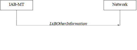
Figure 5.7.12.1-1: IAB Other Information procedure
The IAB Other Information procedure is used
by IAB-MT to request the IAB-donor-CU to allocate IP address or inform the
IAB-donor-CU of the IP address for the collocated IAB-DU.
Upon initiation of the procedure, the
IAB-MT shall:
1> initiate transmission of the IABOtherInformation
message in accordance with 5.7.12.3;
The IAB-MT shall set the contents of IABOtherInformation
message as follows:
1> if the procedure is used to request IP
addresses:
2> if IPv4 addresses are requested:
3> set the iab-IPv4-AddressNumReq to the
number of IPv4 addresses requested per specific usage;
2> if IPv6 addresses or IPv6 address prefixes
are requested:
3> if IPv6 addresses are requested:
4> set the iab-IPv6-AddressNumReq
to the number of IPv6 addresses requested per specific usage;
3> else if IPv6 address prefixes are requested:
4> set the iab-IPv6-AddressPrefixReq to
true per specific usage;
1> if the procedure is used to report IP
addresses:
2> if IPv4 addresses are reported:
3> include iPv4-Address in iab-IPv4-AddressReport,
and for each IP address included:
4> if IPv4 addresses are used for F1-C traffic:
5> include these addresses in f1-C-Traffic-IP-Address.
4> if IPv4 addresses are used for F1-U traffic:
5> include these addresses in f1-U-Traffic-IP-Address.
4> if IPv4 address are used for non-F1 traffic:
5> include these addresses in non-f1-Traffic-IP-Address.
4> if IPv4 addresses are used for all traffic:
5> include these addresses in all-Traffic-IAB-IP-Address.
2> if IPv6 addresses or IPv6 address prefixes
are reported:
3> if IPv6 addresses are reported:
4> include iPv6-Address in iab-IPv6-AddressReport,
and for each IP address included;
5> if IPv6 addresses are used for F1-C traffic:
6> include these
addresses in f1-C-Traffic-IP-Address.
5> if IPv6 addresses are used for F1-U traffic:
6> include these addresses in f1-U-Traffic-IP-Address.
5> if IPv6 addresses are used for non-F1
traffic:
6> include these addresses in non-f1-Traffic-IP-Address.
5> if IPv6 addresses are used for all traffic:
6> include these addresses in all-Traffic-IAB-IP-Address.
3> else if IPv6 address prefixes are reported:
4> include these iPv6-Prefix in iab-IPv6-PrefixReport,
and for each IP address prefix
included;
5> if this IPv6 address prefix is used for F1-C
traffic:
6> include this prefix in f1-C-Traffic-IP-Address.
5> if this IPv6 address prefix is used for F1-U
traffic:
6> include this prefix in f1-U-Traffic-IP-Address.
5> if this IPv6 address prefix is used for
non-F1 traffic:
6> include this prefix in non-f1-Traffic-IP-Address.
5> if this IPv6 address prefix is used for all
traffic:
6> include this prefix in all-Traffic-IAB-IP-Address.
1> if the IAB-MT is in (NG)EN-DC, or
1> if the IAB-MT is in
NR-DC and the IAB Other Information procedure is towards the IAB-donor-CU in
the SN:
2> if SRB3 is configured:
3> submit the IABOtherInformation message
via SRB3 to lower layers for transmission;
2> else if the IAB-MT is in (NG)EN-DC:
3> submit the IABOtherInformation
message via the E-UTRA MCG embedded in E-UTRA RRC message ULInformationTransferMRDC
as specified in TS 36.331 [10];
2> else:
3> submit the IABOtherInformation
message via the NR MCG embedded in NR RRC message ULInformationTransferMRDC
as specified in clause 5.7.2a.3;
1> else:
2> submit the IABOtherInformation
message to lower layers for transmission.
In case both low mobility criterion and
good serving cell criterion are configured for RLM/BFD relaxation, the UE is
allowed to perform RLM and/or BFD relaxation according to requirements
specified in TS 38.133 [14] when both relaxed measurement criterion for low
mobility and relaxed measurement criterion for good serving cell quality are met.
In case only the good serving cell quality
criterion is configured for RLM/BFD relaxation, the UE is allowed to perform
RLM and/or BFD relaxation according to requirements specified in TS 38.133 [14]
when the relaxed measurement criterion for good serving cell quality is met.
When the short DRX cycle is smaller than or
equal to 80 ms and the long DRX cycle is larger than 80 ms then the UE is
allowed to perform RLM and/or BFD relaxation while drx-ShortCycleTimer
is running and the relaxed measurement criteria are met. In this case the UE
does not report change of its relaxation state for RLM and/or BFD relaxation
due to start or stop of drx-ShortCycleTimer, if configured.
5.7.13.1 Relaxed measurement criterion for low mobility
The relaxed measurement criterion for UE with low mobility in RRC_CONNECTED is fulfilled when:
- (SS-RSRPRef – SS-RSRP) < SSearchDeltaP-Connected,
Where:
- SS-RSRP = current L3 RSRP measurement of the SpCell based on SSB (dB).
- SS-RSRPRef = reference L3 RSRP measurement of the SpCell based on SSB (dB), set as follows:
- After receiving low mobility criterion configuration, or
- After MAC of the CG successfully completes a Random
Access procedure after applying a reconfigurationWithSync in spCellConfig of the CG while low mobility criterion is configured, or
- upon an indication from lower layers that a
RACH-less handover or an LTM cell switch is successfully completed for the CG
while low mobility criterion is configured, or
- If (SS-RSRP - SS-RSRPRef) > 0,
or
- If the relaxed measurement criterion has not
been met for TSearchDeltaP-Connected:
- The UE shall set the value of SS-RSRPRef
to the current SS-RSRP value of the SpCell.
5.7.13.2 Relaxed measurement criterion for good
serving cell quality
The relaxed measurement criterion of good serving cell quality for RLM is fulfilled when the downlink radio
link quality on the configured RLM-RS resource is evaluated to be better than the
threshold Qin+XdB, wherein
- Qin is specified
in clause 8.1 of TS 38.133 [14].
- X is the parameter offset
in goodServingCellEvaluationRLM for the evaluated serving cell.
The relaxed measurement criterion of good serving cell quality for BFD is fulfilled when the downlink radio
link quality on the configured BFD-RS resource is
evaluated to be better than the threshold Qin+XdB, wherein
- Q in is specified
in clause 8.1 of TS 38.133 [14].
- X is the parameter offset
in goodServingCellEvaluationBFD for the evaluated serving cell.

Figure 5.7.14.1-1: UE Positioning Assistance
Information procedure
The UE Positioning Assistance Information
procedure is used by UE to report the UE Positioning Assistance Information.
The UE reports the association between SRS resources for positioning and the UE
Tx TEG ID as defined in TS 38.305 [73].
A UE capable of providing the association
between SRS resource for positioning and UE Tx TEG ID in RRC_CONNECTED may
initiate the procedure upon being configured to provide this association
information.
Upon initiation of the procedure, the UE
shall:
1> initiate transmission of the UEPositioningAssistanceInfo
message in accordance with 5.7.14.3 to provide the association.
The UE shall set the contents of the UEPositioningAssistanceInfo
message as follows:
1> if ue-TxTEG-RequestUL-TDOA-Config in RRCReconfiguration
message is configured with periodicReporting:
2> for all the association changes store ue-TxTEG-Association corresponding
to each ue-TxTEG-ID with nr-TimeStamp;
2> include the results in ue-TxTEG-AssociationList in the UEPositioningAssistanceInfo
message on expiry of each configured period;
2> optionally include one ue-TxTEG-TimingErrorMarginValue
for each UEPositioningAssistanceInfo message;
1> else if ue-TxTEG-RequestUL-TDOA-Config
in RRCReconfiguration message is configured with oneShot:
2> identify the ue-TxTEG-Association corresponding to each ue-TxTEG-ID
with nr-TimeStamp;
2> include the results in ue-TxTEG-AssociationList in the UEPositioningAssistanceInfo
message only one time;
2> optionally include one ue-TxTEG-TimingErrorMarginValue
for each UEPositioningAssistanceInfo message.
The UE shall submit the UEPositioningAssistanceInfo
message to lower layers for transmission.
5.7.16 Application
layer measurement reporting
5.7.16.1 General
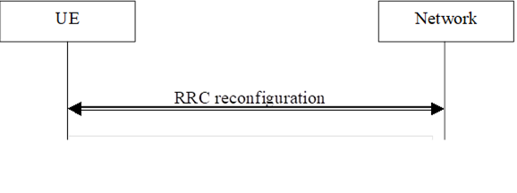
Figure 5.7.16.1-1: Application layer measurement
reporting
The purpose of this
procedure is to send application layer measurement reports to the network.
5.7.16.2 Initiation
A UE capable of application layer
measurement reporting in RRC_CONNECTED may initiate the procedure when
configured with application layer measurement and reporting, i.e. when at
least one measConfigAppLayer and SRB4 and/or SRB5 have been configured
by the network.
Upon initiating the procedure, the UE
shall:
1> for each stored application layer
measurement configuration with appLayerIdleInactiveConfig configured and
for which appLayerIdleInactiveConfig has not been transmitted since the
UE received the RRCSetup message:
2> set the parameters in appLayerIdleInactiveConfig
in the MeasurementReportAppLayer message to the values stored in the UE
variable VarAppLayerIdleConfig;
2> if the transmissionOfSessionStartStop
is set to true:
3> if a session start or stop indication has
been received from upper layers:
4> set the appLayerSessionStatus in the MeasurementReportAppLayer
message to the value of the latest received session start or stop indication;
3> else:
4> set the appLayerSessionStatus in the MeasurementReportAppLayer
message to stop;
1> for each measConfigAppLayerId with an
application layer measurement report container which has not been transmitted
since the UE received the RRCSetup message:
2> if the application layer measurement
reporting has not been suspended for the measConfigAppLayerId associated
with the application layer measurement report container according to clause
5.3.5.13d:
3> set the measConfigAppLayerId in a MeasReportAppLayer
in the MeasurementReportAppLayer message(s) to the value of the measConfigAppLayerId
received together with the application layer measurement report container;
3> for each application measurement report
container stored for that measConfigAppLayerId:
4> set the measReportAppLayerContainerList
in the MeasurementReportAppLayer message(s) to the stored value of the
application layer measurement report container;
NOTE 0: If the size of the application layer
measurement configurations, session status indications and reports exceed the
size of an RRC message, the UE includes the appLayerIdleInactiveConfig
and corresponding appLayerSessionStatus in the first MeasurementReportAppLayer
message after the UE received the RRCSetup message, and transmits
application layer measurement report containers in the same and subsequent MeasurementReportAppLayer
messages.
1> for each measConfigAppLayerId
received from upper layers:
2> if the UE AS has received application layer
measurement report container from upper layers which has not been transmitted;
and
2> if the application layer measurement
reporting has not been suspended for the measConfigAppLayerId associated
with the application layer measurement report container according to clause 5.3.5.13d:
3> set the measReportAppLayerContainer
in the MeasurementReportAppLayer message to the received value in the
application layer measurement report container;
2> set the measConfigAppLayerId in the MeasurementReportAppLayer
message to the value of the measConfigAppLayerId received together with
application layer measurement report information;
2> if session start or stop information has
been received from upper layers for the measConfigAppLayerId:
3> set the appLayerSessionStatus in the MeasurementReportAppLayer
message to the latest received value of session start or stop information;
2> if a RAN visible application layer
measurement report has been received from upper layers:
3> for each appLayerBufferLevel value in
the received RAN visible application layer measurement report:
4> set
the appLayerBufferLevel values in the appLayerBufferLevelList in
the MeasurementReportAppLayer message to the buffer level values
received from the upper layer in the order with the first appLayerBufferLevel
value set to the newest received buffer level value, the second appLayerBufferLevel
value set to the second newest received buffer level value, and so on until
all the buffer level values received from the upper layer have been assigned or
the maximum number of values have been set according to appLayerBufferLevel,
if configured;
3> set the playoutDelayForMediaStartup in
the MeasurementReportAppLayer message to the received value of playout
delay for media startup in the RAN visible application layer measurement
report, if any;
3> for each PDU session ID value indicated in
the received RAN visible application layer measurement report, if any:
4> set the PDU-SessionID
in the pdu-SessionIdList in the MeasurementReportAppLayer message
to the indicated PDU session ID value;
4> for each QoS Flow ID value indicated in the
received RAN visible application layer measurement report associated with the
PDU Session ID, if any:
5> set the QFI associated with the PDU
session ID to the indicated QoS Flow ID value.
1> if reportingSRB (or SRB4 if reportingSRB
is absent) and ran-VisibleReportingSRB (or SRB4 if ran-VisibleReportingSRB
is absent) indicates different SRBs for the measConfigAppLayerId:
2> include measReportAppLayerContainer
and appLayerSessionStatus in a separate MeasurementReportAppLayer
message than ran-VisibleMeasurements;
1> for each encoded MeasurementReportAppLayer
message generated above which contains either only encapsulated application
layer measurement reports or both encapsulated application layer measurement
reports and RAN visible application layer measurement reports:
2> if reportingSRB is not configured for
the measConfigAppLayerId:
3> if the encoded RRC message is larger than
the maximum supported size of one PDCP SDU specified in TS 38.323 [5]:
4> if the RRC message segmentation is enabled
based on the field rrc-SegAllowedSRB4 received in appLayerMeasConfig:
5> initiate the UL message segment transfer procedure as
specified in clause 5.7.7 for transmission via SRB4;
4> else:
5> discard the RRC message;
3> else:
4> submit the MeasurementReportAppLayer
message to lower layers for transmission via SRB4.
2> else if reportingSRB
is configured for the measConfigAppLayerId:
3> if the encoded RRC message is larger than
the maximum supported size of one PDCP SDU specified in TS 38.323 [5]:
4> if the RRC message segmentation is enabled
based on the field rrc-SegAllowedSRB4 received in appLayerMeasConfig
and the reportingSRB is SRB4, or
4> if RRC message segmentation is enabled based
on the field rrc-SegAllowedSRB5 received in appLayerMeasConfig
and the reportingSRB is SRB5:
5> initiate the UL message segment transfer procedure as
specified in clause 5.7.7 for transmission via the SRB indicated in the field reportingSRB in MeasConfigAppLayer;
4> else:
5> discard the RRC message;
3> else:
4> submit the MeasurementReportAppLayer
message to lower layers for transmission via the SRB indicated in the field reportingSRB
in MeasConfigAppLayer.
1> for each encoded MeasurementReportAppLayer
message generated above which contains only RAN visible application layer
measurement reports:
2> if ran-VisibleReportingSRB is not
configured for the measConfigAppLayerId:
3> submit the MeasurementReportAppLayer
message to lower layers for transmission via SRB4;
2> else if ran-VisibleReportingSRB is
configured for the measConfigAppLayerId:
3> submit the MeasurementReportAppLayer
message to lower layers for transmission via the SRB indicated in the field ran-VisibleReportingSRB
in MeasConfigAppLayer.
NOTE 1: If the SRB indicated by reportingSRB
is not available or if reportingSRB is absent and SRB4 is not available,
the UE may store application layer measurement report containers until the SRB
is available. The UE may discard reports when the memory reserved for storing
application layer measurement report containers becomes full. Reports with
lower appLayerMeasPriority are discarded first. If equal or no appLayerMeasPriority
is configured, older reports are discarded first.
NOTE 2: If the SRB indicated by ran-VisibleReportingSRB
is not available or if ran-VisibleReportingSRB
is absent and SRB4 is not available, the UE discards
RAN visible application layer measurement reports.
Upon request from lower layer for pathloss
reference derivation for TA validation for SRS for Positioning transmission or
CG-SDT in RRC_INACTIVE, the UE shall:
1> acquire SIB2, if stored version is
invalid;
1> if nrofSS-BlocksToAverage or absThreshSS-BlocksConsolidation
is not present or if absThreshSS-BlocksConsolidation is present and the
highest beam measurement quantity value is below or equal to absThreshSS-BlocksConsolidation:
2> derive the downlink
pathloss reference RSRP for TA validation as the highest beam measurement
quantity value, where each beam measurement quantity is described in TS 38.215
[24];
1> else:
2> derive the downlink pathloss reference RSRP
for TA validation as the linear average of the power values of up to nrofSS-BlocksToAverage
of the highest beam measurement quantity values above absThreshSS-BlocksConsolidation,
where each beam measurement quantity is described in TS 38.215 [24].
NOTE: If the UE is
configured with multiple SSB configurations, the downlink pathloss reference
RSRP for TA validation is derived from the SSB configured by SIB1.
A UE capable of hard satellite switch with
resynchronization in RRC_CONNECTED initiates the procedure when SatSwitchWithReSync
and t-Service are included in SIB19.
Upon initiating the procedure, the UE
shall:
1> if t-ServiceStart is included in SIB19
and the UE supports soft satellite switch with resynchronization:
2> start acquiring DL synchronization with the
SpCell served by the satellite indicated by ntn-Config in SatSwitchWithReSync
between the time indicated by t-ServiceStart and the time indicated by t-Service
for the serving cell;
1> upon the time indicated by t-Service:
2> stop timer T430 if running;
2> inform lower layers that UL synchronisation
is lost due to satellite switch with resynchronization;
2> synchronise to the DL of the SpCell served
by the satellite indicated by ntn-Config in SatSwitchWithReSync,
if the UE has not previously synchronized to the DL of the SpCell;
2> start timer T430 with the timer value set to
ntn-UlSyncValidityDuration from the subframe indicated by epochTime
in ntn-Config in SatSwitchWithReSync;
2> inform lower layers when UL synchronisation
is obtained.
NOTE: UE should attempt to re-acquire SIB19
after satellite switch with resynchronization. The exact time is left to UE
implementation.
When configured with srs-PosRRC-InactiveValidityAreaPreConfigList,
the UE shall:
1> upon receiving RRCRelease message
after sending the RRCResumeRequest message with the resumeCause
set to srs-PosConfigOrActivationReq:
2> if the current
camped cell is included in any srs-PosConfigValidityArea in the srs-PosRRC-InactiveValidityAreaPreConfigList:
3> apply the corresponding preconfigured SRS
for positioning available in srs-PosRRC-InactiveValidityAreaPreConfigList and instruct lower layers to initiate SRS for Positioning
transmission.
NR sidelink communication consists of
unicast, groupcast and broadcast. For unicast, the PC5-RRC connection is a
logical connection between a pair of a Source Layer-2 ID and a Destination
Layer-2 ID in the AS. The PC5-RRC signalling, as specified in clause 5.8.9, can
be initiated after its corresponding PC5 unicast link establishment (TS 23.287
[55]). The PC5-RRC connection and the corresponding sidelink SRBs and sidelink
DRB(s) are released when the PC5 unicast link is released as indicated by upper
layers.
For each PC5-RRC connection of unicast, one
sidelink SRB (i.e. SL-SRB0) is
used to transmit the PC5-S message(s) before the PC5-S security has been
established. One sidelink SRB
(i.e. SL-SRB1) is used to transmit the PC5-S messages to establish the PC5-S security. One sidelink SRB (i.e. SL-SRB2) is used to transmit the PC5-S messages after the PC5-S security has been established, which is protected. One sidelink SRB (i.e. SL-SRB3) is used to transmit the PC5-RRC signalling,
which is protected and only sent after the PC5-S
security has been established. One sidelink SRB (i.e. SL-SRB4) is used to transmit/receive the NR sidelink discovery messages.
For unicast of NR sidelink communication,
AS security comprises of integrity protection of PC5 signalling (SL-SRB1,
SL-SRB2 and SL-SRB3) and user data (SL-DRBs), and it further comprises of ciphering
of PC5 signaling (SL-SRB1 only for the Direct Link
Security Mode Complete message as specified in TS
24.587 [57] for V2X service or TS 24.554 [72] for
Proximity-services, SL-SRB2 and SL-SRB3) and user data (SL-DRBs). The ciphering
and integrity protection algorithms and parameters for a PC5 unicast link are
exchanged by PC5-S messages in the upper layers as specified in TS 33.536 [60],
and applied to the corresponding PC5-RRC connection in the AS. Once AS security
is activated for a PC5 unicast link in the upper layers as specified in TS
33.536 [60], all messages on SL-SRB2 and SL-SRB3 and/or user data on SL-DRBs of
the corresponding PC5-RRC connection are integrity protected and/or ciphered by
the PDCP.
For unicast of NR sidelink communication,
if the change of the key is indicated by the upper layers as specified in TS 24.587
[57] or TS 24.554 [72], UE re-establishes the PDCP entity of the SL-SRB1,
SL-SRB2, SL-SRB3 and SL-DRBs on the corresponding PC5-RRC connection.
NOTE 1: In case the configurations for NR
sidelink communication are acquired via the E-UTRA, the configurations for NR
sidelink communication in SIB12 and sl-ConfigDedicatedNR within RRCReconfiguration
used in clause 5.8 are provided by the configurations in SystemInformationBlockType28
and sl-ConfigDedicatedForNR within RRCConnectionReconfiguration
as specified in TS 36.331 [10], respectively.
NOTE 2: In this release, there is one-to-one
correspondence between the PC5-RRC connection and the PC5 unicast link as
specified in TS 38.300[2].
NOTE 3: All SL-DRBs related to the same PC5-RRC
connection have the same activation/deactivation setting for ciphering and the
same activation/deactivation setting for integrity protection as specified in
TS 33.536 [60].
NOTE 4: When integrity check failure concerning
SL-SRB1 for a specific destination is detected, the UE sends an indication to
the upper layers [57].
NOTE 5: The selection of
NULL algorithms means that the PC5 messages are considered protected for the
purposes of being allowed to be sent or received.
The UE shall perform NR sidelink
communication/discovery/positioning operation only if the conditions defined in
this clause are met:
1> if the UE's serving cell is suitable
(RRC_IDLE or RRC_INACTIVE or RRC_CONNECTED); and if either the selected cell on
the frequency used for NR sidelink communication/discovery/positioning
operation belongs to the registered or equivalent PLMN as specified in TS
24.587 [57] or TS 24.554 [72] or the UE is out of coverage on the frequency
used for NR sidelink communication/discovery/positioning operation as defined
in TS 38.304 [20] and TS 36.304 [27]; or
1> if the UE's serving cell (RRC_IDLE or
RRC_CONNECTED) fulfils the conditions to support NR sidelink communication/discovery
in limited service state as specified in TS 23.287 [55]; and if either the
serving cell is on the frequency used for NR sidelink communication/discovery
operation or the UE is out of coverage on the frequency used for NR sidelink
communication/discovery operation as defined in TS 38.304 [20] and TS 36.304
[27]; or
1> if the UE has no serving cell (RRC_IDLE).
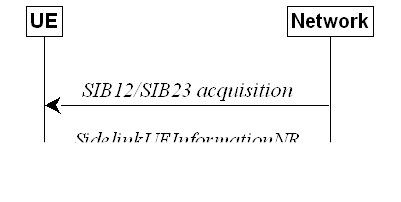
Figure 5.8.3.1-1: Sidelink UE information for NR
sidelink communication/discovery/positioning
The purpose of this procedure is to inform
the network that the UE:
- is interested or no longer interested to
receive or transmit NR sidelink communication/discovery/positioning,
- is requesting assignment or release of
transmission resource for NR sidelink communication/discovery/positioning,
- is reporting QoS parameters and QoS
profile(s) related to NR sidelink communication,
- is reporting mapped frequency(ies) for each
QoS flow related to NR sidelink communication,
- is reporting associated Tx Profile for each
QoS flow related to NR sidelink groupcast and broadcast communication,
- is reporting that a sidelink radio link
failure, sidelink RRC reconfiguration failure or a sidelink carrier failure has
been detected,
- is reporting the sidelink UE capability
information of the associated peer UE for unicast communication,
- is reporting the RLC mode information of the
sidelink data radio bearer(s) received from the associated peer UE for unicast
communication,
- is reporting the accepted
sidelink DRX configuration received from the associated peer UE for NR sidelink
unicast reception,
- is reporting the sidelink DRX assistance
information received from the associated peer UE for NR sidelink unicast transmission,
when the UE is configured with sl-ScheduledConfig,
- is reporting, for NR sidelink groupcast
transmission, the sidelink DRX on/off indication for the associated Destination
Layer-2 ID, when the UE is configured with sl-ScheduledConfig,
- is reporting, for NR sidelink groupcast or
broadcast reception, the Destination Layer-2 ID and QoS profile(s) associated
with its interested services to which sidelink DRX is applied,
- is reporting DRX configuration reject
information from its associated peer UE for NR sidelink unicast transmission,
when the UE is configured with sl-ScheduledConfig,
- is reporting parameters related to U2N relay
operation,
- is reporting parameters related to U2U relay
operation.
A UE capable of NR sidelink communication
or NR sidelink discovery or NR sidelink U2N relay operation or NR sidelink U2U
relay operation or NR sidelink positioning that is in RRC_CONNECTED may
initiate the procedure to indicate it is (interested in) receiving or
transmitting NR sidelink communication or NR sidelink discovery or NR sidelink
U2N relay operation or NR sidelink U2U relay operation or SL-PRS
transmission/reception in several cases including upon successful connection
establishment or resuming, upon change of interest, upon changing QoS profile(s),
upon receiving UECapabilityInformationSidelink from the associated peer
UE, upon RLC mode information updated from the associated peer UE or upon
change to a PCell providing SIB12 including sl-ConfigCommonNR, or upon change to a PCell providing SIB23 including sl-PosConfigCommonNR. A UE capable of NR sidelink communication may initiate the
procedure to request assignment of dedicated sidelink DRB configuration and
transmission resources for NR sidelink communication transmission. A UE capable
of NR sidelink communication may initiate the procedure to report to the
network that a sidelink radio link failure, sidelink RRC reconfiguration
failure or sidelink carrier failure has been declared. A UE capable of NR
sidelink discovery may initiate the procedure to request assignment of
dedicated resources for NR sidelink
discovery transmission or NR sidelink
discovery reception. A UE capable of U2N relay operation may initiate the
procedure to report/update parameters for acting as U2N Relay UE or U2N Remote
UE (including L2 U2N Remote UE's source L2 ID). A UE capable of U2U relay
operation may initiate the procedure to report/update parameters for acting as
U2U Relay UE or U2U Remote UE. A UE capable of NR sidelink positioning may
initiate the procedure to request it is interested or no longer interested in
either transmitting SL-PRS or receiving SL-PRS.
A UE capable of NR sidelink operation that
is in RRC_CONNECTED may initiate the procedure to report the sidelink DRX
configuration received from the associated peer UE for NR sidelink unicast reception,
upon accepting the sidelink DRX configuration from the associated peer UE. A UE
capable of NR sidelink communication that is configured with sl-ScheduledConfig
and is performing sidelink unicast transmission may initiate the procedure to
report the sidelink DRX assistance information or the sidelink DRX configuration
reject information received from the associated peer UE, upon receiving either
of them from the associated peer UE. A UE capable of NR sidelink communication
that is configured with sl-ScheduledConfig and is performing sidelink
groupcast transmission may initiate the procedure to report the sidelink DRX
on/off indication for the associated Destination Layer-2 ID. A UE capable of NR
sidelink communication that is in RRC_CONNECTED may initiate the procedure to
report the frequency(ies) and Tx Profile associated with each QoS flow for NR
sidelink groupcast or broadcast transmission. A UE capable of NR sidelink
communication that is in RRC_CONNECTED may initiate the procedure to report the
frequency(ies) associated with each QoS flow for NR sidelink unicast
transmission.
A UE capable of NR sidelink operation that
is in RRC_CONNECTED may initiate the procedure to report the Destination
Layer-2 ID and QoS profile(s) associated with its interested service(s) that
sidelink DRX is applied, for NR sidelink groupcast or broadcast reception.
Upon initiating this procedure, the UE
shall:
1> if SIB12 including sl-ConfigCommonNR
is provided by the PCell:
2> ensure having a valid version of SIB12 for
the PCell;
2> if configured by upper layers to receive NR
sidelink communication on the frequency included in sl-FreqInfoList/sl-FreqInfoListSizeExt
in SIB12 of the PCell:
3> if the UE did not transmit a SidelinkUEInformationNR
message since last entering RRC_CONNECTED state; or
3> if since the last time the UE transmitted a SidelinkUEInformationNR
message the UE connected to a PCell not providing SIB12 including sl-ConfigCommonNR;
or
3> if the last transmission of the SidelinkUEInformationNR
message did not include sl-RxInterestedFreqList; or if the frequency
configured by upper layers to receive NR sidelink communication on has changed
since the last transmission of the SidelinkUEInformationNR message:
4> initiate transmission of the SidelinkUEInformationNR
message to indicate the NR sidelink communication reception frequency of
interest in accordance with 5.8.3.3;
2> else:
3> if the last transmission of the SidelinkUEInformationNR
message included sl-RxInterestedFreqList:
4> initiate transmission of the SidelinkUEInformationNR
message to indicate it is no longer interested in NR sidelink communication
reception in accordance with 5.8.3.3;
2> if configured by upper layers to transmit non-relay
NR sidelink communication on the frequency included in sl-FreqInfoList/sl-FreqInfoListSizeExt
in SIB12 of the PCell; or
2> if configured by upper layer to transmit NR
sidelink L3 U2U relay communication on the frequency included in
sl-FreqInfoList in SIB12 of the PCell including sl-L3-U2U-RelayDiscovery:
3> if the UE did not transmit a SidelinkUEInformationNR
message since last entering RRC_CONNECTED state; or
3> if since the last time the UE transmitted a SidelinkUEInformationNR
message the UE connected to a PCell not providing SIB12 including sl-ConfigCommonNR;
or
3> if the last transmission of the SidelinkUEInformationNR
message did not include sl-TxResourceReqList; or if the information
carried by the sl-TxResourceReqList has changed since the last
transmission of the SidelinkUEInformationNR message:
4> initiate transmission of the SidelinkUEInformationNR
message to indicate the NR sidelink communication transmission resources
required by the UE in accordance with 5.8.3.3;
2> else:
3> if the last transmission of the SidelinkUEInformationNR
message included sl-TxResourceReqList:
4> initiate transmission of the SidelinkUEInformationNR
message to indicate it no longer requires NR sidelink communication
transmission resources in accordance with 5.8.3.3;
2> if configured by upper layer to receive NR
sidelink non-relay discovery messages on the frequency included in sl-FreqInfoList
in SIB12 of the PCell including sl-NonRelayDiscovery:
3> if the UE did not transmit a SidelinkUEInformationNR
message since last entering RRC_CONNECTED state; or
3> if since the last time the UE transmitted a SidelinkUEInformationNR
message the UE connected to a PCell not providing SIB12 including sl-ConfigCommonNR
or connected to a PCell providing SIB12 but not including sl-NonRelayDiscovery;
or
3> if the last transmission of the SidelinkUEInformationNR
message did not include sl-RxInterestedFreqListDisc; or if the frequency
configured by upper layers to receive NR sidelink non-relay discovery messages on
has changed since the last transmission of the SidelinkUEInformationNR
message:
4> initiate transmission of the SidelinkUEInformationNR
message to indicate the NR sidelink non-relay discovery reception frequency of
interest in accordance with 5.8.3.3;
2> else:
3> if the last transmission of the SidelinkUEInformationNR
message included sl-RxInterestedFreqListDisc:
4> initiate transmission of the SidelinkUEInformationNR
message to indicate it is no longer interested in NR sidelink non-relay discovery
messages reception in accordance with 5.8.3.3;
2> if configured by upper layer to receive NR
sidelink L2 U2N relay discovery messages on the frequency included in sl-FreqInfoList
in SIB12 of the PCell including sl-L2U2N-Relay; or if configured
by upper layer to receive NR sidelink L3 U2N relay discovery messages on the
frequency included in sl-FreqInfoList in SIB12 of the PCell
including sl-L3U2N-RelayDiscovery; or
2> if configured by upper layer to receive NR
sidelink L2 U2U relay discovery messages on the frequency included in sl-FreqInfoList
in SIB12 of the PCell including sl-L2-U2U-Relay; or
2> if configured by upper layer to receive NR
sidelink L3 U2U relay discovery messages on the frequency included in
sl-FreqInfoList in SIB12 of the PCell including sl-L3-U2U-RelayDiscovery:
3> if the UE did not transmit a SidelinkUEInformationNR
message since last entering RRC_CONNECTED state; or
3> if since the last time the UE transmitted a SidelinkUEInformationNR
message the UE connected to a PCell not providing SIB12 including sl-ConfigCommonNR;
or connected to a PCell providing SIB12 but not including sl-L2U2N-Relay
in case of L2 U2N relay operation; or connected to a PCell providing SIB12
but not including sl-L3U2N-RelayDiscovery in case of L3 U2N relay
operation; or
3> if since the last time the UE transmitted a SidelinkUEInformationNR
message the UE connected to a PCell providing SIB12 but not including sl-L2-U2U-Relay
in case of L2 U2U relay operation; or
3> if since the last time the UE transmitted a SidelinkUEInformationNR
message the UE connected to a PCell providing SIB12 but not including sl-L3-U2U-RelayDiscovery
in case of L3 U2U relay operation; or
3> if the last transmission of the SidelinkUEInformationNR
message did not include sl-RxInterestedFreqListDisc; or if the frequency
configured by upper layers to receive NR sidelink relay discovery messages on
has changed since the last transmission of the SidelinkUEInformationNR
message:
4> if the UE is capable of U2N Relay UE, and if
SIB12 includes sl-RelayUE-ConfigCommon; or
4> if the UE is selecting a U2N Relay UE / has
a selected U2N Relay UE, and if SIB12 includes sl-RemoteUE-ConfigCommon; or
4> if the UE is capable
of U2U Relay UE, and if SIB12 includes sl-RelayUE-ConfigCommonU2U;
or
4> if the UE is selecting a U2U Relay UE / has
a selected U2U Relay UE, and if SIB12 includes sl-RemoteUE-ConfigCommonU2U:
5> initiate transmission of the SidelinkUEInformationNR
message to indicate the NR sidelink relay discovery reception frequency of
interest in accordance with 5.8.3.3;
2> else:
3> if the last transmission of the SidelinkUEInformationNR
message included sl-RxInterestedFreqListDisc:
4> initiate transmission of the SidelinkUEInformationNR
message to indicate it is no longer interested in NR sidelink relay discovery messages
reception in accordance with 5.8.3.3;
2> if configured by upper layer to transmit NR
sidelink non-relay discovery messages on the frequency included in sl-FreqInfoList
in SIB12 of the PCell including sl-NonRelayDiscovery:
3> if the UE did not transmit a SidelinkUEInformationNR
message since last entering RRC_CONNECTED state; or
3> if since the last time the UE transmitted a SidelinkUEInformationNR
message the UE connected to a PCell not providing SIB12 including sl-ConfigCommonNR
or connected to a PCell providing SIB12 but not including sl-NonRelayDiscovery;
or
3> if the last transmission of the SidelinkUEInformationNR
message did not include sl-TxResourceReqListDisc; or if the information
carried by the sl-TxResourceReqListDisc has changed since the last
transmission of the SidelinkUEInformationNR message:
4> initiate transmission of the SidelinkUEInformationNR
message to indicate the NR sidelink non-relay discovery messages resources
required by the UE in accordance with 5.8.3.3;
2> else:
3> if the last transmission of the SidelinkUEInformationNR
message included sl-TxResourceReqListDisc:
4> initiate transmission of the SidelinkUEInformationNR
message to indicate it no longer requires NR sidelink non-relay discovery messages
resources in accordance with 5.8.3.3;
2> if configured by upper layer to transmit NR
sidelink L2 U2N relay discovery messages on the frequency included in sl-FreqInfoList
in SIB12 of the PCell including sl-L2U2N-Relay; or if configured
by upper layer to transmit NR sidelink L3 U2N relay discovery messages on the
frequency included in sl-FreqInfoList in SIB12 of the PCell
including sl-L3U2N-RelayDiscovery; or
2> if configured by upper layer to transmit NR
sidelink L2 U2U relay discovery messages on the frequency included in sl-FreqInfoList
in SIB12 of the PCell including sl-L2-U2U-Relay; or
2> if configured by upper layer to transmit NR
sidelink L3 U2U relay discovery messages on the frequency included in
sl-FreqInfoList in SIB12 of the PCell including sl-L3-U2U-RelayDiscovery:
3> if the UE did not transmit a SidelinkUEInformationNR
message since last entering RRC_CONNECTED state; or
3> if since the last time the UE transmitted a SidelinkUEInformationNR
message the UE connected to a PCell not providing SIB12 including sl-ConfigCommonNR;
or connected to a PCell providing SIB12 but not including sl-L2U2N-Relay
in case of L2 U2N relay operation; or connected to a PCell providing SIB12
but not including sl-L3U2N-RelayDiscovery in case of L3 U2N relay
operation; or
3> if since the last time the UE transmitted a SidelinkUEInformationNR
message the UE connected to a PCell providing SIB12 but not including sl-L2-U2U-Relay
in case of L2 U2U relay operation;
3> if since the last time the UE transmitted a SidelinkUEInformationNR
message the UE connected to a PCell providing SIB12 but not including sl-L3-U2U-RelayDiscovery
in case of L3 U2U relay operation; or
3> if the last transmission of the SidelinkUEInformationNR
message did not include sl-TxResourceReqListDisc; or if the information
carried by the sl-TxResourceReqListDisc has changed since the last
transmission of the SidelinkUEInformationNR message:
4> if the UE is capable of U2N Relay UE, and if
SIB12 includes sl-RelayUE-ConfigCommon, and if the U2N Relay UE
threshold conditions as specified in 5.8.14.2 are met; or
4> if the UE is selecting a U2N Relay UE / has
a selected U2N Relay UE/ configured
with measurement object associated to L2 U2N Relay UEs,
and if SIB12 includes sl-RemoteUE-ConfigCommon,
and if the U2N Remote UE threshold conditions as specified in 5.8.15.2 are met;
or
4> if the UE is capable of U2U Relay UE, and if
SIB12 includes sl-RelayUE-ConfigCommonU2U, and if the U2U Relay UE
threshold conditions as specified in 5.8.16.2 are met; or
4> if the UE is selecting a U2U Relay UE / has
a selected U2U Relay UE, and if SIB12 includes sl-RemoteUE-ConfigCommonU2U, and if the U2U Remote
UE threshold conditions as specified in 5.8.17.2 are met:
5> initiate transmission of the SidelinkUEInformationNR
message to indicate the NR sidelink relay discovery messages resources required
by the UE in accordance with 5.8.3.3;
2> else:
3> if the last transmission of the SidelinkUEInformationNR
message included sl-TxResourceReqListDisc:
4> initiate transmission of the SidelinkUEInformationNR
message to indicate it no longer requires NR sidelink relay discovery messages resources
in accordance with 5.8.3.3;
2> if configured by upper layer to transmit NR
sidelink L2 U2N relay communication on the frequency included in sl-FreqInfoList
in SIB12 of the PCell including sl-L2U2N-Relay; or if configured
by upper layer to transmit NR sidelink L3 U2N relay communication on the
frequency included in sl-FreqInfoList in SIB12 of the PCell
including sl-L3U2N-RelayDiscovery; or
2> if configured by upper layer to transmit NR
sidelink L2 U2U relay communication on the frequency included in
sl-FreqInfoList in SIB12 of the PCell including sl-L2-U2U-Relay:
3> if the UE did not transmit a SidelinkUEInformationNR
message since last entering RRC_CONNECTED state; or
3> if since the last time the UE transmitted a SidelinkUEInformationNR
message the UE connected to a PCell not providing SIB12 including sl-ConfigCommonNR;
or connected to a PCell providing SIB12 but not including sl-L2U2N-Relay
in case of L2 U2N relay operation; or connected to a PCell providing SIB12
but not including sl-L3U2N-RelayDiscovery in case of L3 U2N relay
operation; or
3> if since the last time the UE transmitted a SidelinkUEInformationNR
message the UE connected to a PCell providing SIB12 but not including sl-L2-U2U-Relay
in case of L2 U2U relay operation; or
3> if the last transmission of the SidelinkUEInformationNR
message did not include sl-TxResourceReqL2U2N-Relay; or if the information carried by the sl-TxResourceReqL2U2N-Relay has changed since the last
transmission of the SidelinkUEInformationNR message; or if the last
transmission of the SidelinkUEInformationNR message did not include sl-TxResourceReqL3U2N-Relay;
or if the information carried by the sl-TxResourceReqL3U2N-Relay has
changed since the last transmission of the SidelinkUEInformationNR
message; or
3> if the last transmission of the SidelinkUEInformationNR
message did not include sl-TxResourceReqL2-U2U; or if the information
carried by the sl-TxResourceReqL2-U2U has changed since the last
transmission of the SidelinkUEInformationNR message; or
3> if configured by upper layers not to
transmit either NR sidelink L2 U2N relay communication or NR sidelink L3 U2N
relay communication, and if the last transmission of the SidelinkUEInformationNR
message includes both sl-TxResourceReqL2U2N-Relay and sl-TxResourceReqL3U2N-Relay:
4> if the UE is capable of U2N Relay UE; or
4> if the UE is selecting a U2N Relay UE / has
a selected U2N Relay UE; or
4> if the UE is capable of L2 U2U Relay UE; or
4> if the UE is selecting a L2 U2U Relay UE /
has a selected L2 U2U Relay UE:
5> initiate transmission of the SidelinkUEInformationNR
message to indicate the NR sidelink relay communication transmission resources
required by the UE in accordance with 5.8.3.3;
2> else:
3> if the last transmission of the SidelinkUEInformationNR
message included sl-TxResourceReqL2U2N-Relay or sl-TxResourceReqL3U2N-Relay
or sl-TxResourceReqL2-U2U:
4> initiate transmission of the SidelinkUEInformationNR
message to indicate it no longer requires NR sidelink relay communication
transmission resources in accordance with 5.8.3.3;
2> if configured by
upper layers to perform NR
sidelink reception on the
frequency included in sl-FreqInfoList/sl-FreqInfoListSizeExt in SIB12
of the PCell and if sl-DRX-ConfigCommonGC-BC is included in SIB12-IEs:
3> if the UE received a sidelink DRX
configuration in the RRCReconfigurationSidelink message for NR sidelink
unicast reception from the associated peer UE and the UE accepted the sidelink
DRX configuration:
4> if the UE did not transmit a SidelinkUEInformationNR
message since last entering RRC_CONNECTED state; or
4> if since the last time the UE transmitted a SidelinkUEInformationNR
message the UE connected to a PCell not providing SIB12 including sl-DRX-ConfigCommonGC-BC;
or
4> if the last transmission of the SidelinkUEInformationNR
message did not include sl-RxDRX-ReportList; or if the information
carried by sl-RxDRX-ReportList has changed since the last transmission
of the SidelinkUEInformationNR message:
5> initiate transmission of the SidelinkUEInformationNR
message to report the sidelink DRX configuration in accordance with 5.8.3.3;
3> else:
4> if the last transmission of the SidelinkUEInformationNR
message included sl-RxDRX-ReportList:
5> initiate transmission of the SidelinkUEInformationNR
message to indicate the sidelink DRX configuration is no longer used in
accordance with 5.8.3.3;
3> if the UE is performing NR sidelink
groupcast or broadcast reception and is interested in a service that sidelink
DRX is applied:
4> if the UE did not transmit a SidelinkUEInformationNR
message since last entering RRC_CONNECTED state; or
4> if since the last time the UE transmitted a SidelinkUEInformationNR
message the UE connected to a PCell not providing SIB12 including sl-DRX-ConfigCommonGC-BC;
or
4> if the last transmission of the SidelinkUEInformationNR
message did not include sl-RxInterestedGC-BC-DestList; or if the
information carried by sl-RxInterestedGC-BC-DestList has changed since
the last transmission of the SidelinkUEInformationNR message:
5> initiate transmission of the SidelinkUEInformationNR
message to report the Destination Layer-2 ID and QoS profile(s) associated with
the service(s) in accordance with 5.8.3.3;
3> else:
4> if the last transmission of the SidelinkUEInformationNR
message included sl-RxInterestedGC-BC-DestList:
5> initiate transmission of the SidelinkUEInformationNR
message to indicate it is no longer interested in the service that sidelink DRX
is applied in accordance with 5.8.3.3;
2> if configured by upper layers to perform NR sidelink transmission
on the frequency included in sl-FreqInfoList in SIB12
of the PCell and if sl-DRX-ConfigCommonGC-BC is included in SIB12-IEs
and if the UE is configured with sl-ScheduledConfig:
3> if the UE received a sidelink DRX assistance
information or a sidelink DRX configuration reject information from the
associated peer UE for NR sidelink unicast transmission:
4> if the UE did not transmit a SidelinkUEInformationNR
message since last entering RRC_CONNECTED state; or
4> if since the last time the UE transmitted a SidelinkUEInformationNR
message the UE connected to a PCell not providing SIB12 including sl-DRX-ConfigCommonGC-BC;
or
4> if the last transmission of the SidelinkUEInformationNR
message did not include sl-DRX-InfoFromRxList, or sl-FailureList;
or if the information carried by sl-DRX-InfoFromRxList, or sl-FailureList
has changed since the last transmission of the SidelinkUEInformationNR
message:
5> initiate transmission of the SidelinkUEInformationNR
message to report the sidelink DRX assistance information or the sidelink DRX
configuration reject information in accordance with 5.8.3.3;
NOTE: After including the SL-DRX reject
information in sl-FailureList in the last transmission of the SidelinkUEInformationNR
message, it is up to UE implementation to consider another sidelink DRX
rejection of a new SL DRX configuration from the same associated peer UE as
"change" of sl-FailureList.
3> if the UE is performing NR sidelink
groupcast transmission:
4> if the UE did not transmit a SidelinkUEInformationNR
message since last entering RRC_CONNECTED state; or
4> if since the last time the UE transmitted a SidelinkUEInformationNR
message the UE connected to a PCell not providing SIB12 including sl-DRX-ConfigCommonGC-BC;
or
4> if the last transmission of the SidelinkUEInformationNR
message did not include sl-DRX-Indication; or if the information carried
by sl-DRX-Indication has changed since the last transmission of the SidelinkUEInformationNR
message:
5> initiate transmission of the SidelinkUEInformationNR
message to report sidelink DRX on/off indication for the corresponding
destination in accordance with 5.8.3.3;
1> if SIB23 including sl-PosConfigCommonNR
is provided by the PCell:
2> ensure having a valid version of SIB23 for
the PCell;
2> if configured to perform
SL-PRS measurement on the frequency included in sl-PosFreqInfoList
in SIB23 of the PCell:
3> if the UE did not transmit a SidelinkUEInformationNR
message since last entering RRC_CONNECTED state; or
3> if since the last time the UE transmitted a SidelinkUEInformationNR
message the UE connected to a PCell not providing SIB23 including sl-PosConfigCommonNR;
or
3> if the last transmission of the SidelinkUEInformationNR
message did not include sl-PosRxInterestedFreqList; or if the frequency
configured to receive SL-PRS has changed since the last transmission of the SidelinkUEInformationNR
message:
4> initiate transmission of the SidelinkUEInformationNR
message to indicate the frequency of interest for SL-PRS reception in
accordance with 5.8.3.3;
2> else:
3> if the last transmission of the SidelinkUEInformationNR
message included sl-PosRxInterestedFreqList:
4> initiate transmission of the SidelinkUEInformationNR
message to indicate it is no longer interested in SL-PRS reception in
accordance with 5.8.3.3;
2> if configured to transmit SL-PRS on the
frequency included in sl-PosFreqInfoList in SIB23 of the PCell:
3> if the UE did not transmit a SidelinkUEInformationNR
message since last entering RRC_CONNECTED state; or
3> if since the last time the UE transmitted a SidelinkUEInformationNR
message the UE connected to a PCell not providing SIB23 including sl-PosConfigCommonNR;
or
3> if the last transmission of the SidelinkUEInformationNR
message did not include sl-PosTxResourceReqList; or if the information
carried by the sl-PosTxResourceReqList has changed since the last
transmission of the SidelinkUEInformationNR message:
4> initiate transmission of the SidelinkUEInformationNR
message to indicate the NR sidelink positioning transmission resources required
by the UE in accordance with 5.8.3.3;
2> else:
3> if the last transmission of the SidelinkUEInformationNR
message included sl-PosTxResourceReqList:
4> initiate transmission of the SidelinkUEInformationNR
message to indicate it no longer requires NR sidelink positioning transmission
resources in accordance with 5.8.3.3;
The UE shall set the contents of the SidelinkUEInformationNR
message as follows and shall include all concerned information, irrespective of
what triggered the procedure:
1> if the UE initiates the procedure to
indicate it is (no more) interested to receive NR sidelink communication/positioning;
or
1> if the UE initiates the procedure to request
(configuration/ release) of NR sidelink communication/positioning transmission
resources or to report to the network that a sidelink radio link failure,
sidelink RRC reconfiguration failure or sidelink carrier failure has been
declared; or
1> if the UE initiates the procedure to report
to the network the sidelink DRX configuration for NR sidelink unicast reception;
or
1> if the UE initiates the procedure to report
to the network the sidelink DRX assistance information or the sidelink DRX
configuration reject information for NR sidelink unicast transmission; or
1> if the UE initiates the procedure to report to
the network the Destination Layer-2 ID and QoS profile(s) associated with its
interested service(s) that sidelink DRX is applied for NR sidelink groupcast or
broadcast reception; or
1> if the UE initiates the procedure to report
to the network the Destination Layer-2 ID and the sidelink DRX on/off
indication for the corresponding destination for NR sidelink groupcast
transmission; or
1> if the UE initiates the procedure to
indicate it is (no more) interested to receive NR sidelink discovery messages;
or
1> if the UE initiates the procedure to request
(configuration/ release) of NR sidelink discovery messages transmission
resources; or
1> if the UE initiates the procedure to request
(configuration/ release) of NR sidelink U2N or U2U relay communication
transmission resources or report other parameters related to U2N or U2U relay
operation:
2> if SIB12 including sl-ConfigCommonNR
is provided by the PCell:
3> if configured by upper layers to receive NR
sidelink communication:
4> include sl-RxInterestedFreqList and
set it to the frequency for NR sidelink communication reception;
3> if configured by upper layers to transmit non-relay
NR sidelink communication and/or to transmit NR sidelink relay communication;
or
3> if configured by upper layers to transmit NR
sidelink L3 U2U relay communication and SIB12 includes sl-L3-U2U-RelayDiscovery:
4> include sl-TxResourceReqList and set
its fields (if needed) as follows for each destination for which it requests
network to assign NR sidelink communication resource:
5> set sl-DestinationIdentity to the
destination identity configured by upper layer for NR sidelink communication
transmission;
5> set sl-CastType to the cast type of
the associated destination identity configured by the upper layer for the NR
sidelink communication transmission;
5> set sl-RLC-ModeIndicationList to include the RLC mode(s) and
optionally QoS profile(s) of the sidelink QoS flow(s) of the associated RLC
mode(s), if the associated bi-directional sidelink DRB(s) have been established due to the
configuration by
RRCReconfigurationSidelink;
5> set sl-QoS-InfoList to include QoS
profile(s) of the sidelink QoS flow(s) of the associated destination configured
by the upper layer for the NR sidelink communication transmission;
5> set sl-TxInterestedFreqList to
indicate the frequency of the associated destination for NR sidelink
communication transmission;
5> set sl-TypeTxSyncList to the current
synchronization reference type used on the associated sl-TxInterestedFreqList
for NR sidelink communication transmission;
5> set sl-CapabilityInformationSidelink
to include UECapabilityInformationSidelink message, if any, received
from the associated peer UE;
5> if sl-FreqInfoListSizeExt is included
in SIB12-IEs:
6> set sl-QoS-InfoList to include the
frequency(ies), and Tx Profile mapped to the sidelink QoS flow(s) of the
associated destination configured by the upper layer for the NR sidelink groupcast
and broadcast communication transmission;
4> if a sidelink radio link failure or a
sidelink RRC reconfiguration failure has been declared, according to clauses
5.8.9.3 and 5.8.9.1.8, respectively;
5> include sl-FailureList and set its
fields as follows for each destination for which it reports the NR sidelink
communication failure:
6> set sl-DestinationIdentity to the
destination identity configured by upper layer for NR sidelink communication
transmission;
6> if the sidelink RLF is detected as specified
in clause 5.8.9.3:
7> set sl-Failure as rlf for the
associated destination for the NR sidelink communication transmission;
6> else if RRCReconfigurationFailureSidelink
is received:
7> set sl-Failure as configFailure for
the associated destination for the NR sidelink communication transmission;
4> if a sidelink carrier failure has been
indicated by MAC layer;
5> include sl-CarrierFailureList and set
its fields as follows for each destination for which it reports the sidelink
carrier failure:
6> set sl-DestinationIdentity to the
destination identity for which the concerned sidelink carrier failure is
indicated;
6> set sl-CarrierFailure to include the
concerned carrier for which the sidelink carrier failure is indicated;
3> if SIB12 includes sl-NonRelayDiscovery
and if configured by upper layers to receive NR sidelink non-relay discovery messages,
or if SIB12 includes sl-L2U2N-Relay and if configured by upper
layers to receive NR sidelink L2 U2N relay discovery messages, or if SIB12
includes sl-L3U2N-RelayDiscovery and if configured by upper layers to
receive NR sidelink L3 U2N relay discovery messages; or
3> if SIB12 includes sl-L2-U2U-Relay
and if configured by upper layers to receive NR sidelink L2 U2U relay discovery
messages; or
3> if SIB12 includes sl-L3-U2U-RelayDiscovery
and if configured by upper layers to receive NR sidelink L3 U2U relay discovery
messages:
4> include sl-RxInterestedFreqListDisc and
set it to the frequency for NR sidelink discovery messages reception;
3> if SIB12 includes sl-L2U2N-Relay
and the UE is capable of L2 U2N remote UE:
4> include sl-SourceIdentityRemoteUE and
set it to the source identity configured by upper layer for NR sidelink L2 U2N
relay communication transmission;
3> if SIB12 includes sl-NonRelayDiscovery
and if configured by upper layers to transmit NR sidelink non-relay discovery messages,
or if SIB12 includes sl-L2U2N-Relay and if configured by upper
layers to transmit NR sidelink L2 U2N relay discovery messages, or if SIB12
includes sl-L3U2N-RelayDiscovery and if configured by upper layers to
transmit NR sidelink L3 U2N relay discovery messages; or
3> if SIB12 includes sl-L2-U2U-Relay
and if configured by upper layers to transmit NR sidelink L2 U2U relay
discovery messages; or
3> if SIB12 includes sl-L3-U2U-RelayDiscovery
and if configured by upper layers to transmit NR sidelink L3 U2U relay
discovery messages:
4> include sl-TxResourceReqListDisc and
set its fields (if needed) as follows for each destination for which it
requests network to assign NR sidelink discovery messages resource:
5> set sl-DestinationIdentityDisc to the
destination identity configured by upper layer for NR sidelink discovery messages
transmission;
5> if the UE is acting as L2 U2N Relay UE:
6> set sl-SourceIdentityRelayUE to the
source identity configured by upper layer for NR sidelink L2 U2N relay
discovery messages transmission;
5> set sl-CastTypeDisc to the cast type
of the associated destination identity for the NR sidelink discovery messages
transmission;
5> set sl-TxInterestedFreqListDisc to
indicate the frequency of the associated destination for NR sidelink discovery messages
transmission;
5> set sl-TypeTxSyncListDisc to the
current synchronization reference type used on the associated sl-TxInterestedFreqListDisc
for NR sidelink discovery messages transmission;
5> set sl-DiscoveryType to the current
discovery type of the associated destination identity configured by the upper
layer for NR sidelink discovery messages transmission;
5> if the UE is acting as L2/L3 U2U Relay UE:
6> include ue-TypeU2U and set it to relayUE;
5> if the UE is acting as L2/L3 U2U Remote UE:
6> include ue-TypeU2U and set it to remoteUE;
3> if SIB12 includes sl-L2U2N-Relay
and if configured by upper layers to transmit NR sidelink L2 U2N relay
communication and the UE is acting as L2 U2N Relay UE:
4> include sl-TxResourceReqL2U2N-Relay
in sl-TxResourceReqListCommRelay and set its fields (if needed) as
follows for each destination for which it requests network to assign NR
sidelink L2 U2N relay communication resource:
5> set sl-DestinationIdentityL2U2N to
the destination identity configured by upper layer for NR sidelink L2 U2N relay
communication transmission;
5> set sl-TxInterestedFreqListL2U2N to
indicate the frequency of the associated destination for NR sidelink L2 U2N
relay communication transmission;
5> set sl-TypeTxSyncListL2U2N to the
current synchronization reference type used on the associated sl-TxInterestedFreqListL2U2N
for NR sidelink L2 U2N relay communication transmission;
5> set sl-LocalID-Request to request
local ID for L2 U2N Remote UE transiting to RRC_CONNECTED or in RRC_CONNECTED
state;
5> set sl-PagingIdentityRemoteUE to the
paging UE ID received from peer L2 U2N Remote UE, if it is not released as in 5.8.9.8.3;
5> set sl-CapabilityInformationSidelink
to include UECapabilityInformationSidelink message, if any, received
from peer UE;
4> include ue-Type and set it to relayUE;
3> if SIB12 includes sl-L2U2N-Relay
and if configured by upper layers to transmit NR sidelink L2 U2N relay
communication and the UE has a selected L2 U2N Relay UE:
4> include sl-TxResourceReqL2U2N-Relay
in sl-TxResourceReqListCommRelay and set its fields (if needed) as
follows to request network to assign NR sidelink L2 U2N relay communication
resource:
5> set sl-TxInterestedFreqListL2U2N to
indicate the frequency of the associated destination for NR sidelink L2 U2N
relay communication transmission;
5> set sl-TypeTxSyncListL2U2N to the
current synchronization reference type used on the associated sl-TxInterestedFreqListL2U2N
for NR sidelink L2 U2N relay communication transmission;
5> set sl-CapabilityInformationSidelink
to include UECapabilityInformationSidelink message, if any, received
from peer UE;
4> include ue-Type and set it to remoteUE;
3> if SIB12 includes sl-L3U2N-RelayDiscovery
and if configured by upper layers to transmit NR sidelink L3 U2N relay
communication:
4> include sl-TxResourceReqL3U2N-Relay in
sl-TxResourceReqListCommRelay and set its fields (if needed) as follows
for each destination for which it requests network to assign NR sidelink L3 U2N
relay communication resource:
5> set sl-DestinationIdentity to the
destination identity configured by upper layer for NR sidelink L3 U2N relay
communication transmission;
5> set sl-CastType to the cast type of
the associated destination identity configured by the upper layer for the NR
sidelink L3 U2N relay communication transmission;
5> set sl-RLC-ModeIndicationList to include the RLC mode(s) and
optionally QoS profile(s) of the sidelink QoS flow(s) of the associated RLC
mode(s), if the associated bi-directional sidelink DRB(s) have been established due to the
configuration by
RRCReconfigurationSidelink;
5> set sl-QoS-InfoList to include QoS
profile(s) of the sidelink QoS flow(s) of the associated destination configured
by the upper layer for the NR sidelink L3 U2N relay communication transmission;
5> set sl-TxInterestedFreqList to
indicate the frequency of the associated destination for NR sidelink L3 U2N
relay communication transmission;
5> set sl-TypeTxSyncList to the current
synchronization reference type used on the associated sl-TxInterestedFreqList
for NR sidelink L3 U2N relay communication transmission;
5> set sl-CapabilityInformationSidelink
to include UECapabilityInformationSidelink message, if any, received
from peer UE;
4> include ue-Type and set it to relayUE
if the UE is acting as NR sidelink L3 U2N Relay UE or to remoteUE
otherwise;
3> if SIB12 includes sl-L2-U2U-Relay
and if configured by upper layers to transmit NR sidelink L2 U2U relay
communication and the UE is acting as L2 U2U Relay UE:
4> include sl-TxResourceReqL2-U2U and
set its fields (if needed) as follows for each destination for which it
requests network to assign NR sidelink L2 U2U relay communication resource:
5> set sl-DestinationIdentityL2-U2U to
the destination identity configured by upper layer for NR sidelink L2 U2U relay
communication transmission to the target L2 U2U Remote UE;
5> set sl-TxInterestedFreqListL2-U2U to
indicate the frequency of the associated destination for NR sidelink L2 U2U
relay communication transmission;
5> set sl-TypeTxSyncListL2-U2U to the
current synchronization reference type used on the associated sl-InterestedFreqListL2-U2U
for NR sidelink L2 U2U relay communication transmission;
5> set sl-CapabilityInformationSidelink
to include UECapabilityInformationSidelink message, if any, received
from the target L2 U2U Remote UE;
5> include sl-U2U-InfoList and set its
fields (if needed) for each entry as follows, to report the related information
of the connected L2 U2U Remote UEs:
6> include the source L2 U2U Remote UE's L2 ID in
sl-SourceUE-Identity;
6> include sl-PerSLRB-QoS-InfoList, with
each entry including the per-SLRB second-hop QoS profile and the corresponding sl-RemoteUE-SLRB-Identity
which is set to the same value as the sl-E2E-SLRB-Index received in UEInformationRequestSidelink
message from the L2 U2U Remote UE for the same end-to-end SLRB;
5> set sl-RLC-ModeIndicationListL2-U2U
to include the RLC mode(s), if the associated bi-directional PC5 Relay RLC
channel(s) has been established due to the
configuration by
RRCReconfigurationSidelink;
3> if SIB12 includes sl-L2-U2U-Relay
and if configured by upper layers to transmit NR sidelink L2 U2U relay
communication and the UE has a selected L2 U2U Relay UE:
4> include sl-TxResourceReqL2-U2U and
set its fields (if needed) as follows to request network to assign NR sidelink
L2 U2U relay communication resource:
5> set sl-DestinationIdentityL2-U2U to
the destination identity configured by upper layer for NR sidelink L2 U2U relay
communication transmission to L2 U2U Relay UE;
5> set sl-TxInterestedFreqListL2-U2U to
indicate the frequency of the associated destination for NR sidelink L2 U2U
relay communication transmission;
5> set sl-TypeTxSyncListL2-U2U to the
current synchronization reference type used on the associated sl-InterestedFreqListL2-U2U
for NR sidelink L2 U2U relay communication transmission;
5> set sl-CapabilityInformationSidelink
to include UECapabilityInformationSidelink message received from L2 U2U
Relay UE, if any;
5> include sl-U2U-InfoList and set its
fields (if needed) for each entry as follows to report the related end-to-end
and the first hop information for the end-to-end PC5 connection with each target
L2 U2U Remote UE:
6> set sl-TargetUE-Identity to the
destination identity configured by upper layer for NR sidelink L2 U2U relay
communication transmission to the target L2 U2U Remote UE;
6> set sl-E2E-QoS-InfoList to include
end-to-end QoS profile(s) of the sidelink QoS flow(s) of the associated
destination configured by the upper layer for the NR sidelink L2 U2U relay
communication transmission to the target L2 U2U Remote UE;
6> set sl-PerHop-QoS-InfoList to include
the first-hop split PDB of the sidelink QoS flow(s) received from the sl-SplitQoS-InfoListPC5
in UEInformationResponseSidelink message for the associated destination
in accordance with the received sl-TargetUE-Identity;
6> set sl-CapabilityInformationTargetRemoteUE
to include the related UE capability information received from the target L2
U2U Remote UE, if any;
3> if sl-DRX-ConfigCommonGC-BC is
included in SIB12-IEs:
4> if configured by upper layers to perform NR sidelink reception:
5> include sl-RxDRX-ReportList and set
its fields (if needed) as follows for each destination for which it reports to
network:
6> set sl-DRX-ConfigFromTx to include
the accepted sidelink DRX configuration of the associated destination for NR
sidelink unicast communication, if received from the associated peer UE;
5> include sl-RxInterestedGC-BC-DestList
and set its fields (if needed) as follows for each Destination Layer-2 ID for
which it reports to network:
6> set sl-RxInterestedQoS-InfoList to
include the QoS profile of its interested service(s) that sidelink DRX is
applied for the associated destination for NR sidelink groupcast or broadcast reception;
NOTE 1: It is up to UE implementation to set the QoS profile in sl-RxInterestedQoS-InfoList
for reception of NR sidelink discovery message or ProSe Direct Link
Establishment Request message as described in TS 24.554 [72], or for reception
of Direct Link Establishment Request message as described in TS 24.587 [57].
6> set sl-DestinationIdentity to the
associated destination identity configured by upper layer for NR sidelink
groupcast or broadcast reception;
4> if configured by upper layers to perform NR sidelink transmission
and configured with sl-ScheduledConfig:
5> include sl-TxResourceReqList and/or sl-TxResourceReqListCommRelay and/or sl-FailureList and set its
fields (if needed) as follows for each destination for which it reports to
network:
6> set sl-DRX-InfoFromRxList
to include the sidelink DRX assistance information of the associated
destination, if any, received from the associated peer UE;
6> if the RRCReconfigurationCompleteSidelink
message includes the sl-DRX-ConfigReject:
7> set sl-Failure as drxReject-v1710
for the associated destination for the NR sidelink communication transmission;
6> set sl-DRX-Indication to include the
sidelink DRX on/off indication for the associated destination for NR sidelink
groupcast transmission;
3> if SIB12 includes sl-PRS-ResourcesSharedSL-PRS-RP:
4> if configured to perform SL-PRS
measurements:
5> include sl-PosRxInterestedFreqList2
and set it to the frequency configured with sl-PRS-ResourcesSharedSL-PRS-RP
for SL-PRS reception;
4> if configured to transmit SL-PRS:
5> include sl-PosTxResourceReqList and
set its fields (if needed) as follows for each destination for which it
requests network to assign SL-PRS resource:
6> set sl-PosDestinationIdentity to the
destination identity configured by upper layer for SL-PRS transmission;
6> set sl-PosCastType to the cast type
of the associated destination identity configured by the upper layer for SL-PRS
transmission;
6> set sl-PosTxInterestedFreqList2 to
indicate the frequency configured with sl-PRS-ResourcesSharedSL-PRS-RP
of the associated destination for SL-PRS transmission;
6> set sl-PosTypeTxSyncList to the
current synchronization reference type used on the associated sl-PosRxInterestedFreqList
for SL-PRS transmission;
6> set sl-PosQoS-InfoList to include the
SL-PRS transmission QoS profile;
2> if SIB23 including sl-PosConfigCommonNR
is provided by the PCell;
3> if configured to transmit SL-PRS:
4> include sl-PosTxResourceReqList and
set its fields (if needed) as follows for each destination for which it
requests network to assign SL-PRS resource:
5> set sl-PosDestinationIdentity to the
destination identity configured by upper layer for SL-PRS transmission;
5> set sl-PosCastType to the cast type
of the associated destination identity configured by the upper layer for the SL-PRS
transmission;
5> set sl-PosTxInterestedFreqList to
indicate the frequency of the associated destination for SL-PRS transmission;
5> set sl-PosTypeTxSyncList to the
current synchronization reference type used on the associated sl-PosRxInterestedFreqList
for SL-PRS transmission;
5> set sl-PosQoS-InfoList to include the
SL-PRS transmission QoS profile;
3> if configured to perform SL-PRS measurements;
4> include sl-PosRxInterestedFreqList and
set it to the frequency for SL-PRS reception;
1> if the UE initiates the procedure while connected
to an E-UTRA PCell:
2> submit the SidelinkUEInformationNR to lower layers via SRB1, embedded in E-UTRA
RRC message ULInformationTransferIRAT as specified in TS 36.331 [10],
clause 5.6.28;
1> else:
2> submit the SidelinkUEInformationNR
message to lower layers for transmission.
NOTE 2: When multiple lists are reported in SidelinkUEInformationNR, a UE can report
up to maxNrofSL-Dest-r16 SL destinations in sl-TxResourceReqList, sl-TxResourceReqListDisc
and sl-TxResourceReqListCommRelay in total.

Figure 5.8.5.1-1: Synchronisation information transmission
for NR sidelink communication/discovery/positioning, in (partial) coverage

Figure 5.8.5.1-2: Synchronisation information
transmission for NR sidelink communication/discovery/positioning, out of
coverage
The purpose of this procedure is to provide
synchronisation information to a UE. This procedure also applies to NR sidelink
discovery.
A UE capable of NR sidelink communication/discovery/positioning
and SLSS/PSBCH transmission shall, when transmitting NR sidelink communication/discovery/positioning,
and if the conditions for NR sidelink communication/discovery/positioning
operation are met and when the following conditions are met:
1> if in coverage on the frequency used for NR
sidelink communication/discovery/positioning, as defined in TS 38.304 [20]; and
has selected GNSS or the cell as synchronization reference as defined in
5.8.6.3; or
1> if out of coverage on the frequency used for
NR sidelink communication/discovery/positioning, and the frequency used to
transmit NR sidelink communication/discovery is included in sl-FreqInfoToAddModList/sl-FreqInfoToAddModListExt
in sl-ConfigDedicatedNR within RRCReconfiguration message or
included in sl-FreqInfoList/sl-FreqInfoListSizeExt within SIB12;
and has selected GNSS or the cell as synchronization reference as defined in
5.8.6.3:
2> if sl-SyncFreqList is neither
included in RRCReconfiguration nor in SIB12; or
2> if sl-SyncFreqList is included in RRCReconfiguration
or in SIB12; and if none of the frequency(ies) selected as specified in
TS 38.321 [3] is included in the sl-SyncFreqList or the concerned
frequency is selected as the synchronisation carrier frequency in accordance
with 5.8.6.2; or
2> if sl-SyncFreqList and sl-SyncTxMultiFreq
are included in RRCReconfiguration or in SIB12; and if the
concerned frequency has been selected for NR sidelink communication
transmission as specified in TS 38.321 [3] and is included in sl-SyncFreqList;
and if the UE has selected a frequency other than the concerned frequency as
the synchronisation carrier frequency in accordance with 5.8.6.2; and if sl-SyncTxDisabled
corresponding to the concerned frequency is not configured in RRCReconfiguration
or in SIB12:
3> if in RRC_CONNECTED; and if networkControlledSyncTx
is configured and set to on; or
3> if networkControlledSyncTx is not
configured; and for the concerned frequency syncTxThreshIC is
configured; and the RSRP measurement of the reference cell, selected as defined
in 5.8.6.3, for NR sidelink communication/discovery transmission
is below the value of syncTxThreshIC:
4> transmit sidelink SSB on the frequency used
for NR sidelink communication/discovery in accordance with 5.8.5.3 and TS
38.211 [16], including the transmission of SLSS as specified in 5.8.5.3 and
transmission of MasterInformationBlockSidelink as specified in
5.8.9.4.3;
1> else:
2> if sl-SyncFreqList is not included in
SL-PreconfigurationNR; or
2> if sl-SyncFreqList is included in SL-PreconfigurationNR,
and if none of the frequency(ies) selected as specified in TS 38.321 [3] is
included in the sl-SyncFreqList or the concerned frequency is selected
as the synchronisation carrier frequency in accordance with 5.8.6.2; or
2> if sl-SyncFreqList and sl-SyncTxMultiFreq
are included in SL-PreconfigurationNR, and if the concerned frequency
has been selected for NR sidelink communication transmission as specified in TS
38.321 [3] and included in sl-SyncFreqList; and if the UE has selected a
frequency other than the concerned frequency as the synchronisation carrier
frequency in accordance with 5.8.6.2; and if sl-SyncTxDisabled
corresponding to the concerned frequency is not configured in SL-PreconfigurationNR:
3> for the frequency used for NR sidelink
communication/discovery, if syncTxThreshOoC is included in SidelinkPreconfigNR;
and the UE is not directly synchronized to GNSS, and the UE has no selected
SyncRef UE or the PSBCH-RSRP measurement result of the selected SyncRef UE is
below the value of syncTxThreshOoC; or
3> for the frequency used for NR sidelink
communication/discovery, if the UE selects GNSS as the synchronization
reference source:
4> transmit sidelink SSB on the frequency used
for NR sidelink communication/discovery in accordance with 5.8.5.3 and TS
38.211 [16], including the transmission of SLSS as specified in 5.8.5.3 and
transmission of MasterInformationBlockSidelink as specified in
5.8.9.4.3;
The UE shall select the SLSSID and the slot
in which to transmit SLSS as follows:
1> if triggered by NR sidelink communication/discovery/positioning
and in coverage on the frequency used for NR sidelink communication/discovery/positioning,
as defined in TS 38.304 [20]; or
1> if triggered by NR sidelink communication/discovery/positioning,
and out of coverage on the frequency used for NR sidelink communication/discovery/positioning,
and the concerned frequency is included in sl-FreqInfoToAddModList/sl-FreqInfoToAddModListExt
in sl-ConfigDedicatedNR within RRCReconfiguration message or
included in sl-FreqInfoList/sl-FreqInfoToAddModListExt
within SIB12 or SIB23 for NR sidelink positioning:
2> if the UE has selected GNSS as
synchronization reference in accordance with 5.8.6.2:
3> select SLSSID 0;
3> use sl-SSB-TimeAllocation1 included
in the entry of configured sl-SyncConfigList corresponding to the
concerned frequency, that includes txParameters and gnss-Sync;
3> select the slot(s) indicated by sl-SSB-TimeAllocation1;
2> if the UE has selected a cell as
synchronization reference in accordance with 5.8.6.2:
3> select the SLSSID included in the entry of
configured sl-SyncConfigList corresponding to the concerned frequency,
that includes txParameters and does not include gnss-Sync;
3> select the slot(s) indicated by sl-SSB-TimeAllocation1;
1> else if triggered by NR sidelink
communication/discovery and the UE has GNSS as the synchronization reference:
2> select SLSSID 0;
2> if sl-SSB-TimeAllocation3 is
configured for the frequency used in SidelinkPreconfigNR:
3> select the slot(s) indicated by sl-SSB-TimeAllocation3;
2> else:
3> select the slot(s) indicated by sl-SSB-TimeAllocation1;
1> else:
2> select the synchronisation reference UE
(i.e. SyncRef UE) as defined in 5.8.6;
2> if the UE has a selected SyncRef UE and inCoverage
in the MasterInformationBlockSidelink message received from this UE is
set to true; or
2> if the UE has a selected SyncRef UE and inCoverage
in the MasterInformationBlockSidelink message received from this UE is
set to false while the SLSS from this UE is part of the set defined for
out of coverage, see TS 38.211 [16]:
3> select the same SLSSID as the SLSSID of the
selected SyncRef UE;
3> select the slot in which to transmit the
SLSS according to the sl-SSB-TimeAllocation1 or sl-SSB-TimeAllocation2
included in the preconfigured sidelink parameters corresponding to the
concerned frequency, such that the timing is different from the SLSS of the
selected SyncRef UE;
2> else if the UE has a selected SyncRef UE and
the SLSS from this UE was transmitted on the slot(s) indicated sl-SSB-TimeAllocation3,
which is configured for the frequency used in SidelinkPreconfigNR:
3> select SLSSID 337;
3> select the slot(s) indicated by sl-SSB-TimeAllocation2;
2> else if the UE has a selected SyncRef UE:
3> select the SLSSID from the set defined for
out of coverage having an index that is 336 more than the index of the SLSSID
of the selected SyncRef UE, see TS 38.211 [16];
3> select the slot in which to transmit the
SLSS according to sl-SSB-TimeAllocation1 or sl-SSB-TimeAllocation2
included in the preconfigured sidelink parameters corresponding to the
concerned frequency, such that the timing is different from the SLSS of the
selected SyncRef UE;
2> else (i.e. no SyncRef UE selected):
3> if the UE has not randomly selected an
SLSSID:
4> randomly select, using a uniform
distribution, an SLSSID from the set of sequences defined for out of coverage
except SLSSID 336 and 337, see TS 38.211 [16];
4> select the slot in which to transmit the
SLSS according to the sl-SSB-TimeAllocation1 or sl-SSB-TimeAllocation2
(arbitrary selection between these) included in the preconfigured sidelink
parameters in SidelinkPreconfigNR corresponding to the concerned
frequency;

Figure 5.8.5a.1-1: Synchronisation information
transmission for V2X sidelink communication, in (partial) coverage

Figure 5.8.5a.1-2: Synchronisation information
transmission for V2X sidelink communication, out of coverage
The purpose of this procedure is to provide
synchronisation information to a UE.
A UE capable of V2X sidelink communication
initiates the transmission of SLSS and MasterInformationBlock-SL-V2X
according to the conditions and the procedures specified for V2X sidelink
communication in clause 5.10.7 of TS 36.331 [10].
NOTE 1: When applying the procedure in this clause,
SIB13 and SIB14 correspond to SystemInformationBlockType21
and SystemInformationBlockType26 specified in TS 36.331 [10]
respectively.
The purpose of this procedure is to select
a synchronisation reference and used when transmitting NR sidelink
communication/discovery. This procedure also applies to NR sidelink discovery.
The UE shall for frequency(ies) which have
been selected for NR sidelink communication/discovery as specified in TS 38.321
[3]:
1> if sl-SyncFreqList is not included in
RRCReconfiguration nor in SIB12; or
1> if sl-SyncFreqList is included in RRCReconfiguration
or in SIB12, and none of the frequency(ies) selected as specified in TS
38.321 [3] is included in the syncFreqList:
2> if the frequency used for NR sidelink
communication/discovery is included in sl-FreqInfoToAddModList in sl-ConfigDedicatedNR
within RRCReconfiguration message or included in sl-ConfigCommonNR
within SIB12, and sl-SyncPriority is configured for the concerned
frequency and set to gnbEnb:
3> select a cell as the synchronization
reference source as defined in 5.8.6.3:
NOTE 1: When an out of coverage L2 U2N Remote UE
receives SIB12 with sl-SyncPriority set to gnbEnb, the L2 U2N
Remote UE continues using the current synchronization source until higher
priority synchronization source is found or the current synchronization source
becomes unreliable.
2> else if the frequency used for NR sidelink
communication/discovery is included in sl-FreqInfoToAddModList in sl-ConfigDedicatedNR
within RRCReconfiguration message or included in sl-ConfigCommonNR
within SIB12, and sl-SyncPriority for the concerned frequency is
not configured or is set to gnss, and GNSS is reliable in accordance
with TS 38.101-1 [15] and TS 38.133 [14]:
3> select GNSS as the synchronization reference
source;
2> else if the frequency used for NR sidelink
communication/discovery is included in SL-PreconfigurationNR, and sl-SyncPriority
in SidelinkPreconfigNR is set to gnss and GNSS is reliable in
accordance with TS 38.101-1 [15] and TS 38.133 [14]:
3> select GNSS as the synchronization reference
source;
2> else:
3> perform synchronization reference search
procedure as defined in 5.8.6.2b on each frequency which is used for NR
sidelink communication/discovery;
3> if the UE has not selected any
synchronization reference:
4> for each frequency which is used for NR
sidelink communication/discovery:
5> if the UE detects one or more SLSSIDs for
which the PSBCH-RSRP exceeds the minimum requirement defined in TS 38.133 [14]
by sl-SyncRefMinHyst and for which the UE received the corresponding MasterInformationBlockSidelink
message (candidate SyncRef UEs), or if the UE detects GNSS that is reliable in
accordance with TS 38.101-1 [15] and TS 38.133 [14], or if the UE detects a
cell, select a synchronization reference according to the priority group order
as defined in 5.8.6.2a:
1> if sl-SyncFreqList is included in RRCReconfiguration
or in SIB12, and includes at least one of the concerned frequency(ies)
2> if the concerned frequency(ies) are included
in sl-FreqInfoToAddModList/sl-FreqInfoToAddModListExt in sl-ConfigDedicatedNR
within RRCReconfiguration message or included in sl-ConfigCommonNR
within SIB12, and sl-SyncPriority is configured for the concerned
frequency(ies) and set to gnbEnb:
3> select one frequency from the concerned
frequency(ies) which are included in sl-SyncFreqList as the
synchronisation carrier frequency;
3> select a cell in accordance with the
synchronisation carrier frequency as the synchronization reference source as
defined in 5.8.6.3:
2> else if the concerned frequency(ies) are
included in sl-FreqInfoToAddModList/sl-FreqInfoToAddModListExt in
sl-ConfigDedicatedNR within RRCReconfiguration message or
included in sl-ConfigCommonNR within SIB12, and sl-SyncPriority
for concerned frequency(ies) are not configured or are set to gnss, and
GNSS is reliable in accordance with TS 38.101-1 [15] and TS 38.133 [14]; or if
the concerned frequency(ies) are included in SL-PreconfigurationNR, and sl-SyncPriority
in SidelinkPreconfigNR is set to gnss and GNSS is reliable in
accordance with TS 38.101-1 [15] and TS 38.133 [14]:
3> select one frequency from the concerned
frequency(ies) which are included in sl-SyncFreqList as the
synchronisation carrier frequency;
3> select GNSS in accordance with the
synchronisation carrier frequency as the synchronization reference source;
2> else:
3> perform a synchronization reference search
procedure as defined in 5.8.6.2b on each concerned frequency which is included
in sl-SyncFreqList;
3> if the UE has not selected any
synchronization reference:
4> for each concerned frequency which is
included in sl-SyncFreqList:
5> if the UE detects one or more SLSSIDs for
which the PSBCH-RSRP exceeds the minimum requirement defined in TS 38.133 [14]
by sl-SyncRefMinHyst and for which the UE received the corresponding MasterInformationBlockSidelink
message (candidate SyncRef UEs), or if the UE detects GNSS that is reliable in
accordance with TS 38.101-1 [15] and TS 38.133 [14], or if the UE detects a
cell,
6> select the synchronisation reference
source(s) according to the following priority group order as defined in
5.8.6.2a;
6> select the frequency with the highest
synchronisation reference source priority as the synchronisation carrier
frequency, according to the following priority group order as defined in
5.8.6.2a, and consider the synchornization reference source (i.e. eNB/gNB, GNSS
or SyncRef UE) that selected on the synchronisation carrier frequency as the
synchronization reference:
NOTE 2: How the UE achieves subframe boundary
alignment between V2X sidelink communication and NR sidelink communication/discovery
(if both are performed by the UE) is as specified in TS 38.213, clause 16.7.
1> if sl-SyncPriority corresponding to
the concerned frequency is set to gnbEnb:
2> UEs of which SLSSID is part of the set
defined for in coverage, and inCoverage, included in the MasterInformationBlockSidelink
message received from this UE, is set to true, starting with the UE with
the highest PSBCH-RSRP result (priority group 1);
2> UE of which SLSSID is part of the set
defined for in coverage, and inCoverage, included in the MasterInformationBlockSidelink
message received from this UE, is set to false, starting with the UE
with the highest PSBCH-RSRP result (priority group 2);
2> GNSS that is reliable in accordance with TS
38.101-1 [15] and TS 38.133 [14] (priority group 3);
2> UEs of which SLSSID is 0, and inCoverage,
included in the MasterInformationBlockSidelink message received from
this UE, is set to true, or of which SLSSID is 0 and SLSS is transmitted
on slot(s) indicated by sl-SSB-TimeAllocation3, starting with the UE
with the highest PSBCH-RSRP result (priority group 4);
2> UEs of which SLSSID is 0 and SLSS is not
transmitted on slot(s) indicated by sl-SSB-TimeAllocation3, and inCoverage,
included in the MasterInformationBlockSidelink message received from
this UE, is set to false, starting with the UE with the highest
PSBCH-RSRP result (priority group 5);
2> UEs of which SLSSID is 337 and inCoverage,
included in the MasterInformationBlockSidelink message received from
this UE, is set to false, starting with the UE with the highest
PSBCH-RSRP result (priority group 5);
2> Other UEs, starting with the UE with the
highest PSBCH-RSRP result (priority group 6);
1> if sl-SyncPriority corresponding to
the concerned frequency is set to gnss, and sl-NbAsSync is set to
true:
2> UEs of which SLSSID is 0, and inCoverage,
included in the MasterInformationBlockSidelink message received from
this UE, is set to true, or of which SLSSID is 0 and SLSS is transmitted
on slot(s) indicated by sl-SSB-TimeAllocation3, starting with the UE
with the highest PSBCH-RSRP result (priority group 1);
2> UEs of which SLSSID is 0 and SLSS is not
transmitted on slot(s) indicated by sl-SSB-TimeAllocation3, and inCoverage,
included in the MasterInformationBlockSidelink message received from
this UE, is set to false, starting with the UE with the highest
PSBCHS-RSRP result (priority group 2);
2> UEs of which SLSSID is 337 and inCoverage,
included in the MasterInformationBlockSidelink message received from
this UE, is set to false, starting with the UE with the highest
PSBCH-RSRP result (priority group 2);
2> the cell detected by the UE as defined in
5.8.6.3 (priority group 3);
2> UEs of which SLSSID is part of the set
defined for in coverage, and inCoverage, included in the MasterInformationBlockSidelink
message received from this UE, is set to true, starting with the UE with
the highest PSBCH-RSRP result (priority group 4);
2> UE of which SLSSID is part of the set
defined for in coverage, and inCoverage, included in the
MasterInformationBlockSidelink message received from this UE, is set to false,
starting with the UE with the highest PSBCH-RSRP result (priority group 5);
2> Other UEs, starting with the UE with the
highest S-RSRP result (priority group 6);
1> if sl-SyncPriority corresponding to
the concerned frequency is set to gnss, and sl-NbAsSync is set to
false:
2> UEs of which SLSSID is 0, and inCoverage,
included in the MasterInformationBlockSidelink message received from
this UE, is set to true, or of which SLSSID is 0 and SLSS is transmitted
on slot(s) indicated by sl-SSB-TimeAllocation3, starting with the UE
with the highest PSBCH-RSRP result (priority group 1);
2> UEs of which SLSSID is 0 and SLSS is not
transmitted on slot(s) indicated by sl-SSB-TimeAllocation3, and inCoverage,
included in the MasterInformationBlockSidelink message received from this UE,
is set to false, starting with the UE with the highest PSBCHS-RSRP
result (priority group 2);
2> UEs of which SLSSID is 337 and inCoverage,
included in the MasterInformationBlockSidelink message received from
this UE, is set to false, starting with the UE with the highest
PSBCH-RSRP result (priority group 2);
2> Other UEs, starting with the UE with the
highest PSBCH-RSRP result (priority group 3);
The UE shall for the indicated
frequency(ies)
1> perform a full search (i.e. covering all
subframes and all possible SLSSIDs) on each indicated frequency to detect
candidate SLSS, in accordance with TS 38.133 [14];
1> when evaluating the one or more detected
SLSSIDs, apply layer 3 filtering as specified in 5.5.3.2 using the
preconfigured sl-filterCoefficient, before using the PSBCH-RSRP
measurement results;
1> if the UE has selected a SyncRef UE:
2> if the PSBCH-RSRP of the strongest candidate
SyncRef UE exceeds the minimum requirement TS 38.133 [14] by sl-SyncRefMinHyst
and the strongest candidate SyncRef UE belongs to the same priority group as
the current SyncRef UE and the PSBCH-RSRP of the strongest candidate SyncRef UE
exceeds the PSBCH-RSRP of the current SyncRef UE by syncRefDiffHyst; or
2> if the PSBCH-RSRP of the candidate SyncRef
UE exceeds the minimum requirement TS 38.133 [14] by sl-SyncRefMinHyst
and the candidate SyncRef UE belongs to a higher priority group than the
current SyncRef UE; or
2> if GNSS becomes reliable in accordance with
TS 38.101-1 [15] and TS 38.133 [14], and GNSS belongs to a higher priority
group than the current SyncRef UE; or
2> if a cell is detected and gNB/eNB (if sl-NbAsSync
is set to true) belongs to a higher priority group than the current
SyncRef UE; or
2> if the PSBCH-RSRP of the current SyncRef UE
is less than the minimum requirement defined in TS 38.133 [14]:
3> consider no SyncRef UE to be selected;
1> if the UE has selected GNSS as the
synchronization reference for NR sidelink communication/discovery:
2> if the PSBCH-RSRP of the candidate SyncRef
UE exceeds the minimum requirement defined in TS 38.133 [14] by sl-SyncRefMinHyst
and the candidate SyncRef UE belongs to a higher priority group than GNSS; or
2> if GNSS becomes not reliable in accordance
with TS 38.101-1 [15] and TS 38.133 [14]:
3> consider GNSS not to be selected;
1> if the UE has selected cell as the
synchronization reference for NR sidelink communication/discovery:
2> if the PSBCH-RSRP of the candidate SyncRef
UE exceeds the minimum requirement defined in TS 38.133 [14] by sl-SyncRefMinHyst
and the candidate SyncRef UE belongs to a higher priority group than gNB/eNB;
or
2> if the selected cell is not detected:
3> consider the cell not to be selected;
A UE capable of NR sidelink communication/discovery
that is configured by upper layers to transmit NR sidelink communication/discovery
shall:
1> for the frequency used to transmit NR
sidelink communication/discovery, select a cell to be used as reference for
synchronization in accordance with the following:
2> if the frequency concerns the primary
frequency:
3> use the PCell or the serving cell as
reference;
2> else if the frequency concerns a secondary
frequency:
3> use the concerned SCell as reference;
2> else if the UE is in coverage of the
concerned frequency:
3> use the DL frequency paired with the one
used to transmit NR sidelink communication/discovery as reference;
2> else (i.e., out of coverage on the concerned
frequency):
3> use the PCell or the serving cell as
reference, if needed;
A UE capable of NR sidelink communication
that is configured by upper layers to receive NR sidelink communication shall:
1> if the conditions for NR sidelink
communication operation as defined in 5.8.2 are met:
2> if the frequency used for NR sidelink
communication is included in sl-FreqInfoToAddModList/sl-FreqInfoToAddModListExt
in RRCReconfiguration message or sl-FreqInfoList/sl-FreqInfoListSizeExt
included in SIB12:
3> if the UE is configured with sl-RxPool included
in RRCReconfiguration message with reconfigurationWithSync (i.e.
handover):
4> configure lower layers to monitor sidelink
control information and the corresponding data using the pool(s) of resources
indicated by sl-RxPool;
3> else if the cell chosen for NR sidelink
communication provides SIB12:
4> configure lower layers to monitor sidelink
control information and the corresponding data using the pool(s) of resources
indicated by sl-RxPool in SIB12;
2> else:
3> configure lower layers to monitor sidelink
control information and the corresponding data using the pool(s) of resources
that were preconfigured by sl-RxPool in SL-PreconfigurationNR, as
defined in clause 9.3.
A UE capable of NR sidelink communication
that is configured by upper layers to transmit NR sidelink communication and
has related data to be transmitted shall:
1> if the conditions for NR sidelink
communication operation as defined in 5.8.2 are met:
2> if the frequency used for NR sidelink
communication is included in sl-FreqInfoToAddModList/sl-FreqInfoToAddModListExt
in sl-ConfigDedicatedNR within RRCReconfiguration message or
included in sl-ConfigCommonNR within SIB12:
3> if the UE is in RRC_CONNECTED and uses the
frequency included in sl-ConfigDedicatedNR within RRCReconfiguration
message:
4> if the UE acting as
U2U Relay UE is performing U2U Relay Communication with integrated Discovery as
specified in TS 23.304[65] and sl-DiscConfig is
included in RRCReconfiguration, and if the NR
sidelink U2U Relay UE threshold conditions for integrated Discovery as specified in 5.8.16.2 are met based on sl-RelayUE-ConfigU2U; or
4> if the UE capable of
U2U Remote UE is performing U2U Relay Communication with integrated Discovery
as specified in TS 23.304[65] and sl-DiscConfig
is included in RRCReconfiguration, and if the NR
sidelink U2U Remote UE threshold conditions for integrated Discovery as specified in 5.8.17.2 are met based on sl-RemoteUE-ConfigU2U; or
4> if the UE is performing NR sidelink
communication other than U2U Relay Communication with
integrated Discovery:
NOTE 0: For U2U Relay UE,
it can be up to UE implementation on cross-layer interaction for the AS layer
condition check for Direct Communication Request message with integrated
discovery forwarding.
5> if the UE is configured with sl-ScheduledConfig:
6> if T310 for MCG or T311 is running; and if sl-TxPoolExceptional
is included in sl-FreqInfoList/sl-FreqInfoListSizeExt for the
concerned frequency in SIB12 or included in sl-ConfigDedicatedNR
in RRCReconfiguration; or
6> if T301 is running and the cell on which the
UE initiated RRC connection re-establishment provides SIB12 including
sl-TxPoolExceptional for the concerned frequency; or
6> if T304 for MCG is running and the UE is
configured with sl-TxPoolExceptional included in sl-ConfigDedicatedNR for the
concerned frequency in RRCReconfiguration:
7> configure lower layers to perform the
sidelink resource allocation mode 2 based on random selection using the pool of
resources indicated by sl-TxPoolExceptional as defined in TS 38.321 [3];
6> else:
7> configure lower layers to perform the
sidelink resource allocation mode 1 for NR sidelink communication;
6> if T311 is running, configure the lower
layers to release the resources indicated by rrc-ConfiguredSidelinkGrant (if
any);
5> if the UE is configured with
sl-UE-SelectedConfig:
6> if a result of full/partial sensing, if
selected and is allowed by sl-AllowedResourceSelectionConfig, on the
resources configured in sl-TxPoolSelectedNormal for
the concerned frequency included in sl-ConfigDedicatedNR
within RRCReconfiguration is not available in accordance with TS 38.214
[19];
7> if sl-TxPoolExceptional for the
concerned frequency is included in RRCReconfiguration; or
7> if the PCell provides SIB12 including
sl-TxPoolExceptional in sl-FreqInfoList/sl-FreqInfoListSizeExt for the concerned frequency:
8> configure lower layers to perform the
sidelink resource allocation mode 2 based on random selection using the pool of
resources indicated by sl-TxPoolExceptional as defined in TS 38.321 [3];
6> else, if the sl-TxPoolSelectedNormal for the concerned frequency is included in the sl-ConfigDedicatedNR within
RRCReconfiguration:
7> configure lower layers to perform the
sidelink resource allocation mode 2 based on resource selection operation
according to sl-AllowedResourceSelectionConfig (as defined in TS 38.321
[3] and TS 38.214 [19]) using the pools of resources indicated by sl-TxPoolSelectedNormal
for the concerned frequency;
3> else:
4> if the cell chosen for NR sidelink
communication transmission provides SIB12:
5> if the UE acting as
U2U Relay UE is performing U2U Relay communication with integrated Discovery as
specified in TS 23.304[65], and
if the NR sidelink U2U Relay UE threshold conditions for
integrated Discovery as specified in 5.8.16.2 are met
based on sl-RelayUE-ConfigCommonU2U in SIB12; or
5> if the UE capable of
U2U Remote UE is performing U2U Relay Communication with integrated Discovery
as specified in TS 23.304[65], and
if the NR sidelink U2U Remote UE threshold conditions for
integrated Discovery as specified in 5.8.17.2 are met
based on sl-RemoteUE-ConfigCommonU2U in SIB12; or
5> if the UE is performing NR sidelink
communication other than U2U Relay Communication with
integrated Discovery:
6> if SIB12 includes sl-TxPoolSelectedNormal
for the concerned frequency, and a result of full/partial sensing, if
selected and is allowed by sl-AllowedResourceSelectionConfig, on the
resources configured in the sl-TxPoolSelectedNormal is available in
accordance with TS 38.214 [19] or random selection, if allowed by sl-AllowedResourceSelectionConfig,
is selected:
7> configure lower layers to perform the
sidelink resource allocation mode 2 based on resource selection operation
according to sl-AllowedResourceSelectionConfig using the pools of
resources indicated by sl-TxPoolSelectedNormal for the concerned
frequency as defined in TS 38.321 [3];
6> else if SIB12 includes sl-TxPoolExceptional
for the concerned frequency:
7> from the moment the UE initiates RRC
connection establishment or RRC connection resume, until receiving an RRCReconfiguration
including sl-ConfigDedicatedNR, or receiving an RRCRelease or an RRCReject;
or
7> if a result of full/partial sensing, if
selected and is allowed by sl-AllowedResourceSelectionConfig, on the
resources configured in sl-TxPoolSelectedNormal for the concerned
frequency in SIB12 is not available in accordance with TS 38.214 [19]:
8> configure lower layers to perform the
sidelink resource allocation mode 2 based on random selection (as defined in TS
38.321 [3]) using the pool of resources indicated by sl-TxPoolExceptional
for the concerned frequency;
2> else:
3> if the UE acting as
U2U Relay UE is performing U2U Relay communication with integrated Discovery as
specified in TS 23.304[65], and
if the NR sidelink U2U Relay UE threshold conditions for integrated Discovery as
specified in 5.8.16.2 are met based on sl-RelayUE-PreconfigU2U in SidelinkPreconfigNR; or
3> if the UE capable of
U2U Remote UE is performing U2U Relay Communication with integrated Discovery
as specified in TS 23.304[65], and
if the NR sidelink U2U Remote UE threshold conditions for
integrated Discovery as specified in 5.8.17.2 are met
based on sl-RemoteUE-PreconfigU2U in SidelinkPreconfigNR; or
3> if the UE is performing NR sidelink
communication other than U2U Relay Communication with
integrated Discovery:
4> configure lower layers to perform the
sidelink resource allocation mode 2 based on resource selection operation
according to sl-AllowedResourceSelectionConfig (as defined in TS 38.321
[3] and TS 38.214 [19]) using the pools of resources indicated by sl-TxPoolSelectedNormal
in SidelinkPreconfigNR for the concerned
frequency.
NOTE 1: The UE continues to use resources
configured in rrc-ConfiguredSidelinkGrant (while T310 is running) until
it is released (i.e. until T310 has expired). The UE does not use sidelink configured grant type 2 resources while T310 is running.
NOTE 2: In case of RRC reconfiguration with sync,
the UE uses resources configured in rrc-ConfiguredSidelinkGrant (while
T304 on the MCG is running) if provided by the target cell.
NOTE 3: It is up to UE implementation to
determine, in accordance with TS 38.321[3], which resource pool to use if
multiple resource pools are configured, and which resource allocation scheme is
used in the AS based on UE capability (for a UE in RRC_IDLE/RRC_INACTIVE) and
the allowed resource schemes sl-AllowedResourceSelectionConfig in the
resource pool configuration.
NOTE 4: In case that the network does not provide
resource pools in SIB12, a UE which is out of coverage, will be unable
to obtain sidelink resources to send the first UL RRC message.
If configured to perform sidelink resource
allocation mode 2, the UE capable of NR sidelink communication that is
configured by upper layers to transmit NR sidelink communication shall perform resource selection operation according to sl-AllowedResourceSelectionConfig
on all pools of resources which may be used for transmission of the sidelink control information and the corresponding data. The
pools of resources are indicated by SidelinkPreconfigNR, sl-TxPoolSelectedNormal
in sl-ConfigDedicatedNR, or sl-TxPoolSelectedNormal in SIB12
for the concerned frequency, as configured above.
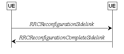
Figure 5.8.9.1.1-1: Sidelink RRC reconfiguration,
successful
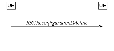
Figure 5.8.9.1.1-2: Sidelink RRC reconfiguration,
failure
The purpose of this procedure is to modify a PC5-RRC connection, e.g. to establish/modify/release
sidelink DRBs or additional sidelink RLC bearer or PC5 Relay RLC channels, to
add/release sidelink carrier, to (re-)configure NR sidelink measurement and reporting, to (re-)configure
sidelink CSI reference signal resources, to (re)configure CSI reporting latency
bound, to (re)configure sidelink DRX, to (re-)configure the latency bound of SL
Inter-UE coordination report, and to indicate the
SFN-DFN offset.
The UE may initiate the sidelink RRC
reconfiguration procedure and perform the operation in clause 5.8.9.1.2 on the corresponding PC5-RRC connection in
following cases:
- the release of sidelink DRBs associated with
the peer UE, or peer L2 U2U Remote UE in case of L2 U2U Relay operation, as
specified in clause 5.8.9.1a.1;
- the establishment of sidelink DRBs associated
with the peer UE, or peer L2 U2U Remote UE in case of L2 U2U Relay operation,
as specified in clause 5.8.9.1a.2;
- the modification for the parameters included
in SLRB-Config of sidelink DRBs associated with the peer UE, or peer L2
U2U Remote UE in case of L2 U2U Relay operation, as specified in clause
5.8.9.1a.2;
- the release of additional sidelink RLC bearer
associated with the peer UE, as specified in clause 5.8.9.1a.5;
- the establishment of additional sidelink RLC
bearer associated with the peer UE, as specified in clause 5.8.9.1a.6;
- the modification for the parameters included
in SL-RLC-BearerConfig of additional sidelink RLC bearer associated with
the peer UE, as specified in clause 5.8.9.1a.6;
- the release of PC5 Relay RLC channels for L2
U2N/U2U Relay UE and Remote UE,
as specified in clause 5.8.9.7.1;
- the establishment of PC5 Relay RLC channels
for L2 U2N/U2U Relay UE and
Remote UE, as specified in clause 5.8.9.7.2;
- the modification for the parameters included
in SL-RLC-ChannelConfigPC5 of PC5 Relay RLC channels for L2 U2N/U2U Relay UE and Remote UE, as specified in
clause 5.8.9.7.2;
- the release of sidelink carrier associated
with the peer UE, as specified in clause 5.8.9.1b.1;
- the addition of sidelink carrier associated
with the peer UE, as specified in clause 5.8.9.1b.2;
- the (re-)configuration of the peer UE to
perform NR sidelink measurement and report.
- the (re-)configuration of the sidelink CSI reference signal resources and CSI
reporting latency bound;
- the (re-)configuration of the peer UE to
perform sidelink DRX;
- the (re-)configuration of the latency bound
of SL Inter-UE coordination report;
- the (re-)configuration of the local UE ID pair
for L2 U2U Remote UE and its peer L2 U2U Remote UE by L2 U2U Relay UE.
- the response to the request in a RemoteUEInformationSidelink
message for the SFN-DFN offset from the L2 U2N Remote UE;
- the change in the value of the SFN-DFN offset
at the L2 U2N Relay UE.
NOTE: It is up to L2 U2N Relay UE
implementation to determine when the SFN-DFN offset has changed in value to a
degree requiring an update to be sent to the L2 U2N Remote UE.
In RRC_CONNECTED, the UE applies the NR
sidelink communications parameters provided in RRCReconfiguration (if
any). In RRC_IDLE or RRC_INACTIVE, the UE applies the NR sidelink
communications parameters provided in system
information (if any). For other cases, UEs apply the NR
sidelink communications parameters provided in SidelinkPreconfigNR (if
any). When UE performs state transition between above three cases, the UE
applies the NR sidelink communications parameters provided in the new state,
after acquisition of the new configurations. Before acquisition of the new
configurations, UE continues applying the NR sidelink communications parameters
provided in the old state.
5.8.9.1.2 Actions related to transmission of RRCReconfigurationSidelink
message
The UE shall set the contents of RRCReconfigurationSidelink message as
follows:
1> for each sidelink DRB that is to be
released, according to clause 5.8.9.1a.1.1, due to configuration by sl-ConfigDedicatedNR, SIB12, SidelinkPreconfigNR, by
upper layers, or due to end-to-end sidelink DRB release:
2> set the entry included in the slrb-ConfigToReleaseList
corresponding to the sidelink DRB;
1> for each sidelink DRB that is to be
established or modified, according to clause 5.8.9.1a.2.1, due to receiving sl-ConfigDedicatedNR, SIB12 or SidelinkPreconfigNR:
2> if the sidelink DRB is a per-hop sidelink
DRB (i.e. the UE is performing NR sidelink communication with a peer UE without
via a L2 U2U Relay UE):
3> if a sidelink DRB is to be established:
4> assign a new logical channel identity for
the logical channel to be associated with the sidelink DRB and set sl-MAC-LogicalChannelConfigPC5 in
the SLRB-Config to include the new logical channel identity;
3> set the SLRB-Config included in the slrb-ConfigToAddModList,
according to the received sl-RadioBearerConfig and sl-RLC-BearerConfig
corresponding to the sidelink DRB;
2> else if the sidelink DRB is an end-to-end
sidelink DRB (i.e. the UE is acting as a L2 U2U Remote UE, and configure peer
L2 U2U Remote UE with end-to-end SDAP and PDCP):
3> set the SLRB-Config
(excluding sl-RLC-ConfigPC5 and sl-MAC-LogicalChannelConfigPC5) included
in the slrb-ConfigToAddModList, according to the received sl-RadioBearerConfig
corresponding to the sidelink DRB;
1> for each additional sidelink RLC bearer that
is to be released, according to clause 5.8.9.1a.5.1, due to configuration by sl-ConfigDedicatedNR,
SIB12, SidelinkPreconfigNR or by upper layers:
2> set the entry included in the sl-RLC-BearerToReleaseList
corresponding to the additional sidelink RLC bearer;
1> for each additional sidelink RLC bearer that
is to be established or modified, according to clause 5.8.9.1a.6.1, due to
receiving sl-ConfigDedicatedNR, SIB12 or SidelinkPreconfigNR:
2> if an additional sidelink RLC bearer is to
be established:
3> assign a new logical channel identity for
the logical channel to be associated with the additional sidelink RLC bearer
and set sl-MAC-LogicalChannelConfigPC5 in the SL-RLC-BearerConfig
to include the new logical channel identity;
2> set the SL-RLC-BearerConfig included
in the sl-RLC-BearerToAddModList, according to the received sl-RadioBearerConfig
and sl-RLC-BearerConfig corresponding to the additional sidelink RLC
bearer;
1> for each carrier that is to be released,
according to clause 5.8.9.1b.1.1:
2> include the corresponding sidelink carrier in
the sl-CarrierToReleaseList;
1> for each carrier that is to be added,
according to clause 5.8.9.1b.2.1:
2> include the corresponding sidelink carrier in
the sl-CarrierToAddModList;
1> set the sl-MeasConfig as follows:
2> If the frequency used for NR sidelink
communication is included in sl-FreqInfoToAddModList/sl-FreqInfoToAddModListExt
in sl-ConfigDedicatedNR within RRCReconfiguration message or
included in sl-ConfigCommonNR within SIB12:
3> if UE is in RRC_CONNECTED:
4> set the sl-MeasConfig according to
stored NR sidelink measurement configuration information for this destination;
3> if UE is in RRC_IDLE or RRC_INACTIVE:
4> set the sl-MeasConfig according to
stored NR sidelink measurement configuration received from SIB12;
2> else:
3> set the sl-MeasConfig according to
the sl-MeasPreConfig in SidelinkPreconfigNR;
1> set the sl-LatencyBoundIUC-Report;
1> start timer T400 for the destination;
1> set the sl-CSI-RS-Config;
1> set the sl-LatencyBoundCSI-Report;
1> set the sl-ResetConfig;
NOTE 1: Whether/how to set the parameters
included in sl-LatencyBoundIUC-Report, sl-CSI-RS-Config, sl-LatencyBoundCSI-Report
and sl-ResetConfig is up to UE implementation.
1> set the sl-DRX-ConfigUC-PC5 as
follows:
2> If the frequency used for NR sidelink
communication is included in sl-FreqInfoToAddModList/sl-FreqInfoToAddModListExt
in sl-ConfigDedicatedNR within RRCReconfiguration message or
included in sl-ConfigCommonNR within SIB12:
3> if UE is in RRC_CONNECTED and if sl-ScheduledConfig
is included in sl-ConfigDedicatedNR within RRCReconfiguration:
4> set the sl-DRX-ConfigUC-PC5 according
to stored NR sidelink DRX configuration information for this destination;
NOTE 2: If UE is in RRC_IDLE or in RRC_INACTIVE
or out of coverage, or in RRC_CONNECTED and sl-UE-SelectedConfig is
included in sl-ConfigDedicatedNR within RRCReconfiguration, it is
up to UE implementation to set the sl-DRX-ConfigUC-PC5.
1> for each PC5 Relay RLC channel that is to be
released due to configuration by sl-ConfigDedicatedNR:
2> set the SL-RLC-ChannelID
corresponding to the PC5 Relay RLC channel in the sl-RLC-ChannelToReleaseListPC5;
1> for each PC5 Relay RLC channel that is to be
established or modified due to receiving sl-ConfigDedicatedNR:
2> if a PC5 Relay RLC
channel is to be established:
3> assign a new logical channel identity for
the logical channel to be associated with the PC5 Relay RLC channel and set sl-MAC-LogicalChannelConfigPC5 in the SL-RLC-ChannelConfigPC5 to include the new logical channel
identity;
2> set the SL-RLC-ChannelConfigPC5
included in the sl-RLC-ChannelToAddModListPC5 according to the received SL-RLC-ChannelConfig
corresponding to the PC5 Relay RLC channel, including setting sl-RLC-ChannelID-PC5
to the same value of sl-RLC-ChannelID received in SL-RLC-ChannelConfig;
1> if the UE is operating as a L2 U2N Relay UE:
2> if the destination UE is a L2 U2N Remote UE
that requested the SFN-DFN offset in a previous RemoteUEInformationSidelink
message:
3> if the SFN-DFN offset has changed since a
previous transmission of the RRCReconfigurationSidelink message, or no
previous transmission of the RRCReconfigurationSidelink message has
occurred since the reception of the RemoteUEInformationSidelink message:
4> set the sl-SFN-DFN-Offset according
to the relation between the SFN timeline of the PCell and the DFN timeline;
1> if the UE is acting as L2 U2U Relay UE, and
if the procedure is initiated to configure local ID pair to a connected L2 U2U
Remote UE:
2> if the local ID pair is to be assigned or
modified for an end-to-end PC5 connection, and if the per-hop PC5-RRC
connection with this L2 U2U Remote UE and the per-hop PC5-RRC connection with its
peer L2 U2U Remote UE are successfully established:
3> include an entry in sl-LocalID-PairToAddModList,
and set the fields as below:
4> set sl-RemoteUE-L2Identity to the
source L2 ID of this L2 U2U Remote UE, and set sl-RemoteUE-LocalIdentity to
include the new local UE ID assigned to this L2 U2U Remote UE, in the
SL-SRAP-ConfigPC5;
4> set sl-PeerRemoteUE-L2Identity to the
source L2 ID of the peer L2 U2U
Remote UE, and set sl-PeerRemoteUE-LocalIdentity to include the new
local UE ID assigned to the peer L2 U2U Remote UE, in the SL-SRAP-ConfigPC5;
1> if the UE is acting as L2 U2U Remote UE
(i.e. Tx UE) and is in RRC_IDLE or in RRC_INACTIVE or out of coverage, and the
procedure is initiated to release the first hop PC5 Relay RLC channel of an
end-to-end sidelink DRB to the connected L2 U2U Relay UE (i.e. Rx UE) according
to clause 5.8.9.7.1; or
1> if the UE is acting as L2 U2U Relay UE (i.e.
Tx UE) and is in RRC_IDLE or in RRC_INACTIVE or out of coverage, and the
procedure is initiated to release the second hop PC5 Relay RLC channel of an
end-to-end sidelink DRB to the connected L2 U2U Remote UE (i.e. Rx UE)
according to clause 5.8.9.7.1:
2> set the SL-RLC-ChannelID
corresponding to the PC5 Relay RLC channel in the sl-RLC-ChannelToReleaseListPC5;
1> if the UE is acting as L2 U2U Remote UE
(i.e. Tx UE) and is in RRC_IDLE or in RRC_INACTIVE or out of coverage, and if
the procedure is initiated to add/modify the first hop PC5 Relay RLC channel of
an end-to-end sidelink DRB to
the connected L2 U2U Relay UE (i.e. Rx UE), based on configuration in SIB12 or SidelinkPreconfigNR; or
1> if the UE is acting as L2 U2U Relay UE (i.e.
Tx UE) and is in RRC_IDLE or in RRC_INACTIVE or out of coverage, and if the
procedure is initiated to add/modify the second hop PC5 Relay RLC channel to
the connected L2 U2U Remote UE (i.e. Rx UE) based on configuration in SIB12 or SidelinkPreconfigNR:
2> if a PC5 Relay RLC
channel is to be established:
3> assign a new RLC channel ID and set sl-RLC-ChannelID-PC5
in the SL-RLC-ChannelConfigPC5 to include the new RLC channel ID;
3> assign a new logical channel identity for
the logical channel to be associated with the PC5 Relay RLC channel and set sl-MAC-LogicalChannelConfigPC5 in the SL-RLC-ChannelConfigPC5 to include the new logical channel
identity;
2> if the UE is in RRC_IDLE or in RRC_INACTIVE:
3> set the SL-RLC-ChannelConfigPC5
included in the sl-RLC-ChannelToAddModListPC5 according to the SL-RLC-BearerConfig
derived based on the per-hop QoS of the end-to-end SLRB according to sl-RLC-BearerConfigList
in SIB12;
2> else if the UE is out of coverage:
3> set the SL-RLC-ChannelConfigPC5
included in the sl-RLC-ChannelToAddModListPC5 according to the SL-RLC-BearerConfig
derived based on the per-hop QoS of the end-to-end SLRB according to sl-RLC-BearerPreConfigList
in SidelinkPreconfigNR.
NOTE 3: Void.
The UE shall submit the RRCReconfigurationSidelink message to
lower layers for transmission.
The UE shall perform the following actions
upon reception of the RRCReconfigurationSidelink:
1> if the RRCReconfigurationSidelink includes
the sl-ResetConfig:
2> perform the sidelink reset configuration
procedure as specified in 5.8.9.1.10;
1> if the RRCReconfigurationSidelink includes
the slrb-ConfigToReleaseList:
2> for each entry value included in the slrb-ConfigToReleaseList that is part
of the current UE sidelink configuration;
3> perform the sidelink
DRB release procedure, according to clause 5.8.9.1a.1;
1> if the RRCReconfigurationSidelink includes
the slrb-ConfigToAddModList:
2> for each slrb-PC5-ConfigIndex
value included in the slrb-ConfigToAddModList
that is not part of the current UE sidelink configuration:
3> if sl-MappedQoS-FlowsToAddList is
included:
4> apply the SL-PQFI included in sl-MappedQoS-FlowsToAddList;
3> perform the sidelink
DRB addition procedure, according to clause 5.8.9.1a.2;
2> for each slrb-PC5-ConfigIndex
value included in the slrb-ConfigToAddModList
that is part of the current UE sidelink configuration:
3> if sl-MappedQoS-FlowsToAddList is
included:
4> add the SL-PQFI
included in sl-MappedQoS-FlowsToAddList to the corresponding sidelink
DRB;
3> if sl-MappedQoS-FlowsToReleaseList is
included:
4> remove the SL-PQFI
included in sl-MappedQoS-FlowsToReleaseList from the corresponding
sidelink DRB;
3> if the sidelink DRB release conditions as
described in clause 5.8.9.1a.1.1 are met:
4> perform the sidelink DRB release procedure
according to clause 5.8.9.1a.1.2;
3> else if the sidelink DRB modification
conditions as described in clause 5.8.9.1a.2.1 are met:
4> perform the sidelink DRB modification
procedure according to clause 5.8.9.1a.2.2;
1> if the RRCReconfigurationSidelink
includes the sl-RLC-BearerToReleaseList:
2> for each entry value included in the sl-RLC-BearerToReleaseList
that is part of the current UE sidelink configuration;
3> perform the additional sidelink RLC bearer
release procedure, according to clause 5.8.9.1a.5;
1> if the RRCReconfigurationSidelink
includes the sl-RLC-BearerToAddModList:
2> for each SL-RLC-BearerConfigIndex
value included in the sl-RLC-BearerToAddModList that is not part of the
current UE sidelink configuration:
3> perform the additional sidelink RLC bearer
addition procedure, according to clause 5.8.9.1a.6;
2> for each SL-RLC-BearerConfigIndex
value included in the sl-RLC-BearerToAddModList that is part of the
current UE sidelink configuration:
3> perform the additional sidelink RLC bearer
modification procedure, according to clause 5.8.9.1a.6;
1> if the RRCReconfigurationSidelink
includes the sl-CarrierToReleaseList:
2> for each entry value included in the sl-CarrierToReleaseList
that is part of the current UE sidelink configuration;
3> perform the sidelink carrier release
procedure, according to clause 5.8.9.1b.1;
1> if the RRCReconfigurationSidelink
includes the sl-CarrierToAddModList:
2> for each sl-CarrierId value included
in the sl-CarrierToAddModList that is not part of the current UE
sidelink configuration:
3> perform the sidelink carrier addition
procedure, according to clause 5.8.9.1b.2;
1> if the RRCReconfigurationSidelink message includes the sl-MeasConfig:
2> perform the sidelink measurement
configuration procedure as specified in 5.8.10;
1> if the RRCReconfigurationSidelink message includes the sl-CSI-RS-Config:
2> apply the sidelink CSI-RS configuration;
1> if the RRCReconfigurationSidelink message includes the sl-LatencyBoundCSI-Report:
2> apply the configured sidelink CSI report
latency bound;
1> if the RRCReconfigurationSidelink includes
the sl-RLC-ChannelToReleaseListPC5:
2> for each SL-RLC-ChannelID
value included in the sl-RLC-ChannelToReleaseListPC5
that is part of the current UE sidelink configuration;
3> perform the PC5
Relay RLC channel release procedure, according to
clause 5.8.9.7.1;
1> if the RRCReconfigurationSidelink includes
the sl-RLC-ChannelToAddModListPC5:
2> for each sl-RLC-ChannelID-PC5
value included in the sl-RLC-ChannelToAddModListPC5
that is not part of the current UE sidelink configuration:
3> perform the PC5 Relay RLC channel addition procedure,
according to clause 5.8.9.7.2;
2> for each sl-RLC-ChannelID-PC5
value included in the sl-RLC-ChannelToAddModListPC5
that is part of the current UE sidelink configuration:
3> perform the PC5 Relay RLC channel
modification procedure according to clause 5.8.9.7.2;
1> if the RRCReconfigurationSidelink message includes the sl-DRX-ConfigUC-PC5; and
1> if the UE accepts the sl-DRX-ConfigUC-PC5:
2> configure lower layers to perform sidelink
DRX operation according to sl-DRX-ConfigUC-PC5 for the associated
destination as defined in TS 38.321 [3];
1> if the RRCReconfigurationSidelink message includes the sl-LatencyBoundIUC-Report:
2> apply the configured sidelink IUC report
latency bound;
1> if the RRCReconfigurationSidelink message includes the sl-LocalID-PairToAddModList:
2> configure SRAP entity to perform NR sidelink
L2 U2U relay operation accordingly for the end-to-end PC5 connection with the peer
L2 U2U Remote UE as defined in TS 38.351 [65];
1> if the UE is unable to comply with (part of)
the configuration included in the RRCReconfigurationSidelink (i.e. sidelink RRC
reconfiguration failure):
2> continue using the configuration used prior
to the reception of the RRCReconfigurationSidelink message;
2> set the content of the RRCReconfigurationFailureSidelink message;
3> submit the RRCReconfigurationFailureSidelink message to lower layers for transmission;
1> if the RRCReconfigurationSidelink message includes the sl-SFN-DFN-Offset:
2> if the sl-SFN-DFN-Offset is set to setup:
3> apply the configured
SFN-DFN time offset;
2> if the sl-SFN-DFN-Offset is set to release:
3> release the received sl-SFN-DFN-Offset;
1> else:
2> set the content of the RRCReconfigurationCompleteSidelink
message;
3> if the UE rejects the sidelink DRX
configuration sl-DRX-ConfigUC-PC5 received from the peer UE:
4> include the sl-DRX-ConfigReject in
the RRCReconfigurationCompleteSidelink message;
4> consider no sidelink DRX to be applied for
the corresponding sidelink unicast communication;
3> submit the RRCReconfigurationCompleteSidelink message to lower layers for transmission;
NOTE 1: When the same logical channel is
configured with different RLC mode by another UE, the
UE handles the case as sidelink RRC reconfiguration failure.
NOTE 2: It is up to the UE implementation whether
or not to indicate the rejection to the peer UE for a received sidelink DRX
configuration.
NOTE 3: When UE transmits SL-PRS in dedicated SL-PRS resource pool, the
sidelink DRX configuration is not applied.
The UE shall perform the following actions
upon reception of the RRCReconfigurationFailureSidelink:
1> stop timer T400 for the destination, if
running;
1> continue using the configuration used prior
to corresponding RRCReconfigurationSidelink message;
1> if UE is in RRC_CONNECTED:
2> perform the sidelink UE information for NR
sidelink communication procedure, as specified in 5.8.3.3 or clause 5.10.15 in
TS 36.331 [10];
The UE shall perform the following actions
upon reception of the RRCReconfigurationCompleteSidelink:
1> stop timer T400 for the destination, if
running;
1> consider the configurations in the
corresponding RRCReconfigurationSidelink message to be applied.
2> if the RRCReconfigurationCompleteSidelink
message includes the sl-DRX-ConfigReject:
3> consider no sidelink DRX to be applied for
the corresponding sidelink unicast communication.
5.8.9.1.10 Sidelink
reset configuration
The UE shall:
1> release/clear current sidelink radio
configuration of this destination received in the RRCReconfigurationSidelink;
1> release the sidelink DRBs of this
destination, in according to clause 5.8.9.1a.1;
1> release the additional sidelink RLC bearer
of this destination, if configured, in according to clause 5.8.9.1a.5;
1> reset the sidelink specific MAC of this destination, except for end-to-end PC5 connection in L2 U2U
Relay operation.
NOTE 1: Sidelink radio configuration is not just
the resource configuration but may include other configurations included in the
RRCReconfigurationSidelink message except the sidelink DRBs of this
destination.
NOTE 2: After the
sidelink DRB release procedure, UE may perform the sidelink DRB addition
according to the current sidelink configuration of this destination, received in sl-ConfigDedicatedNR, SIB12 and
SidelinkPreconfigNR, according to clause
5.8.9.1a.2.
5.8.9.1a.1.1 Sidelink DRB release
conditions
For NR sidelink communication, a sidelink
DRB release is initiated in the following cases:
1> for groupcast, broadcast and unicast, if slrb-Uu-ConfigIndex
(if any) of the sidelink DRB is included in sl-RadioBearerToReleaseList in
sl-ConfigDedicatedNR; or
1> for groupcast and broadcast, if no sidelink
QoS flow with data indicated by upper layers is mapped to the sidelink DRB for
transmission, which is (re)configured by receiving SIB12 or SidelinkPreconfigNR;
or
1> for groupcast,
broadcast and unicast, if SL-RLC-BearerConfigIndex (if any) of the
sidelink DRB is included in sl-RLC-BearerToReleaseList/sl-RLC-BearerToReleaseListSizeExt
in sl-ConfigDedicatedNR; or
1> for unicast, if no sidelink QoS flow with
data indicated by upper layers is mapped to the sidelink DRB for transmission,
which is (re)configured by receiving SIB12 or SidelinkPreconfigNR,
and if no sidelink QoS flow mapped to the sidelink DRB, which is (re)configured
by receiving RRCReconfigurationSidelink, has data; or
1> for unicast, if SLRB-PC5-ConfigIndex (if
any) of the sidelink DRB is included in slrb-ConfigToReleaseList
in RRCReconfigurationSidelink or if sl-ResetConfig is included in RRCReconfigurationSidelink; or
1> for unicast, when the corresponding PC5-RRC
connection is released due to sidelink RLF being detected, according to clause
5.8.9.3; or
1> for unicast, when
the corresponding PC5-RRC connection is released due to upper layer request
according to clause 5.8.9.5; or
1> for L2 U2U relay operation, when the corresponding end-to-end PC5 connection failure is detected
according to clause 5.8.9.3a;
or
1> for L2 U2U relay operation, when the corresponding end-to-end PC5-RRC connection is
released due to upper layer request according to
clause 5.8.9.5a.
5.8.9.1a.1.2 Sidelink DRB release
operations
For each sidelink
DRB, whose sidelink DRB release conditions are met as in clause 5.8.9.1a.1.1, the UE capable of NR sidelink communication that is
configured by upper layers to perform NR sidelink communication shall:
1> for groupcast and broadcast; or
1> for unicast, if the sidelink DRB release was triggered after the reception of
the RRCReconfigurationSidelink message; or
1> for unicast, after
receiving the RRCReconfigurationCompleteSidelink message, if the
sidelink DRB release was triggered due to the configuration
received within the sl-ConfigDedicatedNR, SIB12,
SidelinkPreconfigNR or indicated by upper layers:
2> release the PDCP entity for NR sidelink
communication associated with the sidelink DRB;
2> if SDAP entity for
NR sidelink communication associated with this sidelink
DRB is configured:
3> indicate the release of the sidelink DRB to
the SDAP entity associated with this sidelink DRB (TS 37.324 [24], clause 5.3.3);
2> release SDAP entities for NR sidelink
communication, if any, that have no associated sidelink DRB as specified in TS
37.324 [24] clause 5.1.2;
1> for groupcast and broadcast; or
1> for unicast, after receiving the RRCReconfigurationCompleteSidelink
message, if the sidelink DRB release was triggered due to the configuration received within the sl-ConfigDedicatedNR:
2> for each sl-RLC-BearerConfigIndex
included in the received sl-RLC-BearerToReleaseList/sl-RLC-BearerToReleaseListSizeExt
that is part of the current UE sidelink configuration:
3> release the RLC entity and the corresponding
logical channel for NR sidelink communication, associated with the sl-RLC-BearerConfigIndex.
1> if the sidelink DRB
is a per-hop sidelink DRB (i.e. the UE is performing NR
sidelink communication with a peer UE without via a L2 U2U Relay UE):
2> for unicast, if the sidelink DRB release was
triggered due to the reception of the RRCReconfigurationSidelink
message; or
2> for unicast, after receiving the RRCReconfigurationCompleteSidelink
message, if the sidelink DRB release was triggered due to the configuration received within the SIB12, SidelinkPreconfigNR or indicated by upper layers:
3> release the RLC entity and the corresponding
logical channel for NR sidelink communication associated with the sidelink DRB;
3> perform the sidelink UE information
procedure in clause 5.8.3 for unicast if needed.
1> if the sidelink radio link failure is
detected for a specific destination:
2> release the PDCP entity, RLC entity and the
logical channel of the sidelink DRB for the specific destination.
1> if the UE is acting
as a L2 U2U Remote UE, and if the end-to-end sidelink
DRB release is triggered by end-to-end PC5 connection
failure due to per-hop PC5 link failure, in accordance with clause 5.8.9.3a:
2> release the PDCP entity(ies) of the
end-to-end sidelink DRB(s) for
the specific end-to-end PC5 connection;
1> if the sidelink DRB
is an end-to-end sidelink DRB in L2 U2U relay operation and the UE is acting as
a L2 U2U remote UE:
2> trigger the UE information transfer
procedure on sidelink as specified in 5.8.9.11.2;
5.8.9.1a.2.1 Sidelink DRB
addition/modification conditions
For NR sidelink communication, a sidelink
DRB addition is initiated only
in the following cases:
1> if any sidelink QoS flow is (re)configured
by sl-ConfigDedicatedNR, SIB12, SidelinkPreconfigNR and
is to be mapped to one sidelink DRB, which is not established; or
1> if any sidelink QoS flow is (re)configured
by RRCReconfigurationSidelink and is to be mapped to a sidelink
DRB, which is not established;
1> if any sidelink QoS flow is (re)configured
by source L2 U2U Remote UE and is mapped to an end-to-end sidelink DRB for
transmission when the UE is acting as L2 U2U Relay UE;
The above conditions also apply to L2 U2U
Remote UE for end-to-end sidelink DRB addition.
For NR sidelink communication, a sidelink
DRB modification is initiated only in the
following cases:
1> if any of the sidelink DRB related
parameters is changed by sl-ConfigDedicatedNR, SIB12, SidelinkPreconfigNR or
RRCReconfigurationSidelink for one sidelink DRB, which is
established;
The above conditions also apply to L2 U2U
Remote UE for end-to-end sidelink DRB modification.
5.8.9.1a.2.2 Sidelink DRB
addition/modification operations
For the sidelink
DRB, whose sidelink DRB addition conditions are met as in clause 5.8.9.1a.2.1,
the UE capable of NR sidelink communication that is configured by upper layers
to perform NR sidelink communication shall:
1> for groupcast and broadcast; or
1> for unicast, if the sidelink DRB addition was triggered due to the reception of
the RRCReconfigurationSidelink message; or
1> for unicast, after receiving the RRCReconfigurationCompleteSidelink
message, if the sidelink DRB addition was triggered due to the configuration received within the
sl-ConfigDedicatedNR, SIB12, SidelinkPreconfigNR or
indicated by upper layers:
2> if an SDAP entity for NR sidelink
communication associated with the destination and the cast type of the sidelink
DRB does not exist:
3> establish an SDAP entity for NR sidelink
communication as specified in TS 37.324 [24] clause 5.1.1;
2> (re)configure the SDAP entity in accordance
with the sl-SDAP-ConfigPC5 received in the RRCReconfigurationSidelink
or sl-SDAP-Config received in sl-ConfigDedicatedNR, SIB12,
SidelinkPreconfigNR, associated with the sidelink DRB;
2> establish a PDCP entity for NR sidelink
communication and configure it in accordance with the sl-PDCP-ConfigPC5
received in the RRCReconfigurationSidelink or sl-PDCP-Config received in sl-ConfigDedicatedNR, SIB12,
SidelinkPreconfigNR, associated with the sidelink DRB;
2> for a per-hop sidelink DRB (i.e. the UE is performing
NR sidelink communication with a peer UE without via a L2 U2U Relay UE):
3> establish a RLC entity for NR sidelink
communication and configure it in accordance with the sl-RLC-ConfigPC5 received in the RRCReconfigurationSidelink or sl-RLC-Config received in sl-ConfigDedicatedNR, SIB12, SidelinkPreconfigNR, associated with sidelink DRB;
3> if this procedure was due to the reception of a RRCReconfigurationSidelink
message:
4> configure the MAC entity with a logical
channel in accordance with the sl-MAC-LogicalChannelConfigPC5 received
in the RRCReconfigurationSidelink associated with the sidelink DRB, and
perform the sidelink UE information procedure in clause 5.8.3 for unicast if
needed;
3> else if this procedure was due to the reception of a RRCReconfigurationCompleteSidelink
message:
4> configure the MAC entity with a logical
channel associated with the
sidelink DRB, in accordance with the sl-MAC-LogicalChannelConfig
received in the sl-ConfigDedicatedNR, SIB12, SidelinkPreconfigNR;
3> else (i.e. for groupcast/broadcast):
4> configure the MAC entity with a logical
channel associated with the
sidelink DRB, in accordance with the sl-MAC-LogicalChannelConfig
received in the sl-ConfigDedicatedNR, SIB12, SidelinkPreconfigNR
and assign a new LCID to this logical channel.
1> if the DRB is an end-to-end sidelink DRB and
the UE is acting as L2 U2U Remote UE:
2> trigger the UE information transfer
procedure on sidelink as specified in 5.8.9.11.2;
NOTE 1: When a sidelink DRB addition is due to the configuration by RRCReconfigurationSidelink, it is up to UE implementation
to select the sidelink DRB configuration as necessary transmitting parameters
for the sidelink DRB, from the received
sl-ConfigDedicatedNR (if in
RRC_CONNECTED), SIB12 (if in
RRC_IDLE/INACTIVE), SidelinkPreconfigNR (if out of coverage) with the same RLC mode
as the one configured in RRCReconfigurationSidelink.
For the sidelink
DRB, whose sidelink DRB modification conditions are met
as in clause 5.8.9.1a.2.1, the UE capable of NR
sidelink communication that is configured by upper layers to perform NR
sidelink communication shall:
1> for groupcast and broadcast; or
1> for unicast, if the sidelink DRB
modification was triggered due to the reception of the RRCReconfigurationSidelink
message; or
1> for unicast, after receiving the RRCReconfigurationCompleteSidelink
message, if the sidelink DRB modification was triggered due to the configuration received within the sl-ConfigDedicatedNR, SIB12 or
SidelinkPreconfigNR:
2> reconfigure the SDAP
entity of the sidelink DRB, in accordance with the sl-SDAP-ConfigPC5 received in the RRCReconfigurationSidelink or sl-SDAP-Config received in sl-ConfigDedicatedNR, SIB12,
SidelinkPreconfigNR, if included;
2> reconfigure the PDCP
entity of the sidelink DRB, in
accordance with the sl-PDCP-ConfigPC5 received in the RRCReconfigurationSidelink or
sl-PDCP-Config received in sl-ConfigDedicatedNR, SIB12,
SidelinkPreconfigNR, if included;
2> reconfigure the RLC
entity of the sidelink DRB, in accordance with the sl-RLC-ConfigPC5 received in the RRCReconfigurationSidelink or sl-RLC-Config
received in sl-ConfigDedicatedNR, SIB12,
SidelinkPreconfigNR, if included;
2> reconfigure the
logical channel of the sidelink DRB, in accordance with the sl-MAC-LogicalChannelConfigPC5 received in the RRCReconfigurationSidelink or sl-MAC-LogicalChannelConfig
received in sl-ConfigDedicatedNR, SIB12,
SidelinkPreconfigNR, if included;
1> if the DRB is an end-to-end sidelink DRB and the UE is acting as L2
U2U Remote UE:
2> trigger the UE information transfer
procedure on sidelink as specified in 5.8.9.11.2.
The UE shall:
1> if a PC5-RRC connection release for a
specific destination is requested by upper layers or AS layer; or
1> if the sidelink radio link failure is
detected for a specific destination:
2> release the PDCP entity, RLC entity and the
logical channel of the sidelink SRB for PC5-RRC message of the specific
destination;
2> consider the PC5-RRC connection is released
for the destination.
1> if PC5-S transmission for a specific
destination is terminated in upper layers:
2> release the PDCP entity, RLC entity and the
logical channel of the sidelink SRB(s) for PC5-S message of the specific
destination if any;
1> if discovery transmission for a specific
destination is terminated in upper layers:
2> release the PDCP entity, RLC entity and the
logical channel of the sidelink SRB4 for discovery message of the specific
destination;
1> if an end-to-end PC5-RRC connection
release/failure is detected:
2> if the UE is acting L2 U2U Remote UE:
3> release the PDCP entity of the end-to-end
sidelink SRB for the end-to-end PC5 connection;
2> release the association between the
end-to-end sidelink SRB and the egress PC5 Relay RLC channel, and reconfigure
SRAP configuration.
The UE shall:
1> if transmission of PC5-S message for a
specific destination is requested by upper layers for sidelink SRB:
2> establish PDCP entity, RLC entity and the
logical channel of a sidelink SRB for PC5-S message if needed, as specified in clause
9.1.1.4;
2> if in coverage on the frequency used for the
NR sidelink communication as defined in TS 38.304 [20]:
3> indicate the allowed carrier for the RLC
bearer of the SRB before the reception of initial RRCReconfigurationCompleteSidelink
message which confirms SL CA carrier(s) addition as indicated in sl-FreqInfoList, to
lower layer;
2> else:
3> indicate the allowed carrier for the RLC
bearer of the SRB before the reception of initial RRCReconfigurationCompleteSidelink
message which confirms SL CA carrier(s) addition as indicated in sl-PreconfigFreqInfoList, to lower layer;
1> if transmission of discovery message for a
specific destination is requested by upper layers for sidelink SRB:
2> establish PDCP entity, RLC entity and the
logical channel of a sidelink SRB4 for discovery message, as specified in clause
9.1.1.4;
1> if a PC5-RRC connection establishment for a
specific destination is indicated by upper layers:
2> establish PDCP entity, RLC entity and the
logical channel of a sidelink SRB for PC5-RRC message of the specific
destination if needed, as specified in clause 9.1.1.4;
2> consider the PC5-RRC connection is
established for the destination;
2> if in coverage on the frequency used for the
NR sidelink communication as defined in TS 38.304 [20]:
3> indicate the allowed carrier for the RLC
bearer of the SRB before the reception of initial RRCReconfigurationCompleteSidelink
message which confirms SL CA carrier(s) addition, as indicated in sl-FreqInfoList,
to lower layer;
2> else:
3> indicate the allowed carrier for the RLC
bearer of the SRB before the reception of initial RRCReconfigurationCompleteSidelink
message which confirms SL CA carrier(s) addition as specified in clause
5.8.9.1.9, as indicated in sl-PreconfigFreqInfoList, to lower layer;
1> for end-to-end SRB0/1/2/3:
2> if the UE is acting L2 U2U Remote UE:
3> consider the SL-U2U-RLC as specified in clause 9.1.1.4 as the egress PC5 Relay RLC channel;
4> associate this
end-to-end sidelink SRB with the SL-U2U-RLC and configure the mapping between
the end-to-end sidelink SRB and
the egress PC5 Relay RLC channel to SRAP.
For NR sidelink communication, additional
sidelink RLC bearer release is initiated in the following cases:
1> for sidelink DRB, the release conditions are
met as in clause 5.8.9.1a.1.1 for the associated sidelink DRB; or
1> for sidelink SRB
1/2/3, the release conditions are met as in clause
5.8.9.1a.3 for the associated sidelink SRB; or
1> for sidelink DRB, if SL-RLC-BearerConfigIndex
(if any) of the sidelink DRB is included in sl-RLC-BearerToReleaseList
in RRCReconfigurationSidelink; or
1> for sidelink DRB, if SL-RLC-BearerConfigIndex
(if any) of the additional Sidelink RLC Bearer is included in sl-RLC-BearerToReleaseListSizeExt
in sl-ConfigDedicatedNR;
The UE shall:
1> for groupcast and broadcast; or
1> for unicast, after receiving the RRCReconfigurationCompleteSidelink
message, if the additional sidelink RLC bearer release was triggered due to the
configuration received within the sl-ConfigDedicatedNR:
2> for each sl-RLC-BearerConfigIndex
included in the received sl-RLC-BearerToReleaseListSizeExt in sl-ConfigDedicatedNR
that is part of the current UE sidelink configuration:
3> release the RLC entity and the corresponding
logical channel of the additional sidelink RLC bearer for NR sidelink
communication, associated with the sl-RLC-BearerConfigIndex.
1> for unicast, if the additional sidelink RLC
bearer release was triggered due to the reception of the RRCReconfigurationSidelink
message:
2> for each SL-RLC-BearerConfigIndex
included in received sl-RLC-BearerToReleaseList in RRCReconfigurationSidelink
that is part of the current UE sidelink configuration:
3> release the RLC entity and the corresponding
logical channel of the additional sidelink RLC bearer for NR sidelink
communication associated with the SL-RLC-BearerConfigIndex;
1> for unicast, after receiving the RRCReconfigurationCompleteSidelink
message, if the additional sidelink RLC bearer release was triggered due to the
configuration received within the SIB12, SidelinkPreconfigNR or
indicated by upper layers:
2> for each SL-RLC-BearerConfigIndex
included in transmitted sl-RLC-BearerToReleaseList in RRCReconfigurationSidelink
that is part of the current UE sidelink configuration:
3> release the RLC entity and the corresponding
logical channel of the additional sidelink RLC bearer for NR sidelink
communication associated with the SL-RLC-BearerConfigIndex;
For NR sidelink communication, additional
sidelink RLC bearer addition is initiated only in the following cases:
1> for unicast, for sidelink DRB, if SL-RLC-BearerConfig
is received in sl-RLC-BearerToAddModList in the RRCReconfigurationSidelink
for a slrb-PC5-ConfigIndex; or
1> for groupcast and broadcast, for sidelink
DRB, if SL-RLC-BearerConfig is received in sl-RLC-BearerToAddModListSizeExt
in sl-ConfigDedicatedNR for a sl-ServedRadioBearer; or
1> for unicast, for sidelink DRB, if SL-RLC-BearerConfig
is received in sl-RLC-BearerToAddModListSizeExt in sl-ConfigDedicatedNR
for a sl-ServedRadioBearer; or
1> for groupcast and broadcast, for sidelink
DRB, if SL-RLC-BearerConfig is received in sl-RLC-BearerConfigListSizeExt
in SIB12 or in SidelinkPreconfigNR for a sl-ServedRadioBearer,
if the sidelink DRB has been established as in clause 5.8.9.1a.2 and has not
been released as in clause 5.8.9.1a.1, and if the SL-TxProfile of all
associated QoS flow(s) for the sl-ServedRadioBearer indicates backwardsIncompatible;
or
1> for groupcast and broadcast, for sidelink
DRB, if SL-RLC-BearerConfig is received in sl-RLC-BearerConfigListSizeExt
in SIB12 or in SidelinkPreconfigNR for a sl-ServedRadioBearer,
if the sidelink DRB has been established as in clause 5.8.9.1a.2 and has not
been released as in clause 5.8.9.1a.1, and if the SL-TxProfile of at
least one QoS flow for the sl-ServedRadioBearer indicates backwardsCompatible
and UE decides to use PDCP duplication; or
1> for unicast, for sidelink DRB, if SL-RLC-BearerConfig
is received in sl-RLC-BearerConfigListSizeExt in SIB12 or in SidelinkPreconfigNR
for a sl-ServedRadioBearer, and if both UEs support PDCP duplication; or
1> for unicast, for sidelink SRB 1/2/3, if both UEs support PDCP duplication
and UE decides to use PDCP duplication;
For NR sidelink communication, additional
sidelink RLC bearer modification is initiated only in the following cases:
1> if any of the additional sidelink RLC bearer
related parameters is changed by sl-ConfigDedicatedNR, SIB12, SidelinkPreconfigNR
or RRCReconfigurationSidelink for one additional sidelink RLC bearer,
which is established;
For the additional Sidelink RLC bearer,
whose addition conditions are met as in clause 5.8.9.1a.6.1, the UE capable of
NR sidelink communication that is configured by upper layers to perform NR
sidelink communication shall:
1> for groupcast and broadcast; or
1> for unicast, if the additional Sidelink RLC
bearer addition was triggered due to the reception of the RRCReconfigurationSidelink
message; or
1> for unicast, for DRB, after receiving the RRCReconfigurationCompleteSidelink
message, if the additional Sidelink RLC bearer addition was triggered due to
the configuration received within the sl-ConfigDedicatedNR, SIB12,
SidelinkPreconfigNR or indicated by upper layers; or
1> for unicast, for SRB, after receiving the RRCReconfigurationCompleteSidelink
message, if the additional Sidelink RLC bearer addition was decided by UE:
2> establish an additional RLC entity for NR
sidelink communication and configure it in accordance with each sl-RLC-ConfigPC5
received in the RRCReconfigurationSidelink or sl-RLC-Config
received in sl-ConfigDedicatedNR, SIB12, SidelinkPreconfigNR
for SL DRB, or as specified in clause 9.1.1.4 for SL SRB;
2> if this procedure was for Sidelink DRB:
3> if this procedure was due to the reception
of a RRCReconfigurationSidelink message:
4> configure the MAC entity with a logical
channel in accordance with the sl-MAC-LogicalChannelConfigPC5 received
in the RRCReconfigurationSidelink associated with the sidelink RLC
entity;
3> else if this procedure was due to the
reception of a RRCReconfigurationCompleteSidelink message:
4> configure the MAC entity with a logical
channel associated with the sidelink RLC entity, in accordance with the sl-MAC-LogicalChannelConfig
received in the sl-ConfigDedicatedNR, SIB12, SidelinkPreconfigNR;
3> else (i.e. for groupcast/broadcast):
4> configure the MAC entity with a logical
channel associated with the sidelink RLC entity, in accordance with the sl-MAC-LogicalChannelConfig
received in the sl-ConfigDedicatedNR, SIB12, SidelinkPreconfigNR
and assign a new LCID to this logical channel.
3> if the UE is in RRC_CONNECTED:
4> indicate the allowed carriers for the two
RLC bearers of the DRB, as indicated in sl-AllowedCarriers, to lower
layer;
3> else:
4> indicate the allowed carriers for the two
RLC bearers of the DRB, decided by UE implementation, from the sidelink
carrier(s) mapped to the sidelink QoS flow(s) configured by the upper layer
which is allowed carrier as indicated in sl-FregInfoList as specified in
5.8.9.1a.4 or is additional allowed carrier(s) as specified in 5.8.9.1b.1.2 and
5.8.9.1b.2.2, to lower layer,
where the carrier indicated in sl-FreqInfoList is used for the RLC
bearer if the SL-TxProfile of at least one associated QoS flow for the sl-ServedRadioBearer
indicates backwardsCompatible, and the allowed
carriers for the two RLC bearers are not overlapping with each other;
2> else (i.e., if this procedure was for
Sidelink SRB):
3> configure the MAC entity with a logical
channel associated with the sidelink RLC entity, as specified in clause
9.1.1.4.
3> if the UE is in RRC_CONNECTED and if sl-AllowedCarrierFreqSet1/sl-AllowedCarrierFreqSet2
are configured:
4> indicate the allowed carriers for the two
RLC bearers of the SRB, as indicated in sl-AllowedCarrierFreqSet1/sl-AllowedCarrierFreqSet2,
to lower layer;
3> else:
4> indicate the allowed carriers for the two
RLC bearers of the SRB, decided by UE implementation, from the allowed carrier
as indicated in sl-FregInfoList as specified in 5.8.9.1a.4 and
additional allowed carrier(s) as specified in 5.8.9.1b.1.2 and 5.8.9.1b.2.2, to lower layer, where the allowed carriers for the two RLC bearers are not overlapping
with each other;
For the additional Sidelink RLC bearer,
whose modification conditions are met as in clause 5.8.9.1a.6.1, the UE capable
of NR sidelink communication that is configured by upper layers to perform NR
sidelink communication shall:
1> for groupcast and broadcast; or
1> for unicast, if the additional Sidelink RLC
bearer modification was triggered due to the reception of the RRCReconfigurationSidelink
message; or
1> for unicast, after receiving the RRCReconfigurationCompleteSidelink
message, if the additional Sidelink RLC bearer modification was triggered due
to the configuration received within the sl-ConfigDedicatedNR, SIB12
or SidelinkPreconfigNR:
2> reconfigure the RLC entity of the sidelink
DRB, in accordance with the sl-RLC-ConfigPC5 received in the RRCReconfigurationSidelink
or sl-RLC-Config received in sl-ConfigDedicatedNR, SIB12, SidelinkPreconfigNR,
if included;
2> reconfigure the logical channel of the
sidelink DRB, in accordance with the sl-MAC-LogicalChannelConfigPC5
received in the RRCReconfigurationSidelink or sl-MAC-LogicalChannelConfig
received in sl-ConfigDedicatedNR, SIB12, SidelinkPreconfigNR,
if included.
For NR sidelink communication, sidelink
carrier release is initiated in the following cases:
1> for unicast, if sl-CarrierId of the
sidelink carrier is received in sl-CarrierToReleaseList in the RRCReconfigurationSidelink;
or
1> for unicast, if a sidelink carrier failure
has been indicated by MAC layer; or
1> for unicast, if the sidelink carrier release
was triggered due to the configuration received within the sl-ConfigDedicatedNR,
SIB12, SidelinkPreconfigNR or upper layer; or
1> for unicast, if the sidelink SRB(s), DRB(s)
or additional sidelink RLC bearer(s), which was associated with the sidelink
carrier(s), are released according to clause 5.8.9.1a.3.1, 5.8.9.1a.1.1 or
5.8.9.1a.5.1;
5.8.9.1b.1.2 Sidelink Carrier
Release Operation
The UE shall:
1> for unicast, if the sidelink carrier release
was triggered due to the reception of the RRCReconfigurationSidelink
message:
2> for each sl-CarrierId value included
in the sl-CarrierToReleaseList:
3> if the current UE configuration includes a
sidelink carrier with value sl-CarrierId:
4> release the sidelink carrier for reception.
1> for unicast, after receiving the RRCReconfigurationCompleteSidelink
message, if the sidelink carrier release was triggered due to the configuration
received within the sl-ConfigDedicatedNR, SIB12, SidelinkPreconfigNR
or indicated by upper layers:
2> for each sl-CarrierId value included
in the sl-CarrierToReleaseList:
3> if the current UE configuration includes a
sidelink carrier with value sl-CarrierId:
4> release the sidelink carrier for
transmission;
4> indicate the sidelink carrier not as allowed
carrier for the RLC bearer of the SRB to lower layer;
4> indicate the sidelink carrier not as
additional allowed carrier for the RLC bearer of the DRB(s), to lower layer.
For NR sidelink communication, sidelink
carrier addition is initiated in the following cases:
1> for unicast, if sl-CarrierId of the
sidelink carrier is received in sl-CarrierToAddModList in the RRCReconfigurationSidelink;
or
1> for unicast, if a sidelink SRB(s), DRB(s) or
additional sidelink RLC bearer(s), which is associated with the sidelink
carrier(s) (taking into account at least carrier(s) mapped to the sidelink QoS
flow(s) configured by the upper layer, carriers configured in sl-ConfigDedicatedNR,
SIB12 or SidelinkPreconfigNR, and carrier(s) supported by both
UEs), are established according to clause 5.8.9.1a.4, 5.8.9.1a.2.1 or
5.8.9.1a.6.1;
5.8.9.1b.2.2 Sidelink Carrier Addition
Operation
The UE shall:
1> for unicast, if the sidelink carrier
addition was triggered due to the reception of the RRCReconfigurationSidelink
message:
2> for each sl-CarrierId value included
in the sl-CarrierToAddModList that is not part of the current UE
configuration (sidelink carrier addition):
3> add the sidelink carrier, corresponding to
the sl-CarrierId, in accordance with the sl-OffsetToCarrier, subcarrierSpacing,
carrierBandwidth and sl-AbsoluteFrequencyPointA for reception;
1> for unicast, after receiving the RRCReconfigurationCompleteSidelink
message, if the sidelink carrier addition was triggered due to the
configuration received within the sl-ConfigDedicatedNR, SIB12, SidelinkPreconfigNR
or indicated by upper layers:
2> for each sl-CarrierId value included
in the sl-CarrierToAddModList that is not part of the current UE
configuration (sidelink carrier addition):
3> add the sidelink carrier, corresponding to
the sl-CarrierId, in accordance with the sl-AbsoluteFrequencyPointA
for transmission;
3> indicate the sidelink carrier as additional
allowed carrier for the RLC bearer of the SRB, in addition to carrier as indicated in sl-FreqInfoList, from
carrier(s) mapped to the sidelink QoS flow(s) configured by the upper layer, to lower layer;
3> indicate the sidelink carrier as additional
allowed carrier for the RLC bearer of the DRB(s), for which the sidelink
carrier is mapped to the sidelink QoS flow(s) configured by the upper layer, to
lower layer;
This clause describes how the UE compiles
and transfers its sidelink UE capability information for unicast to the
initiating UE.
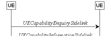
Figure 5.8.9.2.1-1: Sidelink UE capability
transfer
The UE may initiate the sidelink UE
capability transfer procedure upon indication from upper layer when it needs
(additional) UE radio access capability information.
The initiating UE shall set the contents of
UECapabilityEnquirySidelink message as follows:
1> include in UE radio access capabilities for
sidelink within ue-CapabilityInformationSidelink, if needed;
NOTE 1: It is up to initiating UE to decide
whether ue-CapabilityInformationSidelink should be included.
1> set frequencyBandListFilterSidelink
to include frequency bands for which the peer UE is
requested to provide supported bands and band combinations;
NOTE 2: The initiating UE is not allowed to send
the UECapabilityEnquirySidelink message without including the field frequencyBandListFilterSidelink
except for end-to-end L2 U2U relay NR sidelink
communication.
1> submit the UECapabilityEnquirySidelink
message to lower layers for transmission.
The peer UE shall set the contents of UECapabilityInformationSidelink
message as follows:
1> include UE radio access capabilities for
sidelink within ue-CapabilityInformationSidelink;
1> compile a list of "candidate band
combinations" only consisting of bands included in frequencyBandListFilterSidelink,
and prioritized in the order of frequencyBandListFilterSidelink (i.e.
first include band combinations containing the first-listed band, then include
remaining band combinations containing the second-listed band, and so on).
1> include into supportedBandCombinationListSidelinkNR
as many band combinations as possible from the list of "candidate band
combinations", starting from the first entry;
1> include the received frequencyBandListFilterSidelink
in the field appliedFreqBandListFilter of the requested UE capability;
1> submit the UECapabilityInformationSidelink
message to lower layers for transmission.
NOTE 1: If the UE cannot include all band
combinations due to message size or list size constraints, it is up to UE
implementation which band combinations it prioritizes.
NOTE 2: It is up to UE
implementation whether to include fields other than pdcp-ParametersSidelink
in the UECapabilityInformationSidelink message for end-to-end L2 U2U relay NR sidelink communication.
The UE shall:
1> upon indication from sidelink RLC entity
that the maximum number of retransmissions for a specific destination has been
reached; or
1> upon T400 expiry for a specific destination; or
1> upon indication from MAC entity that HARQ-based
Sidelink RLF for a specific destination has been detected; or
1> upon integrity check failure indication from
sidelink PDCP entity concerning SL-SRB2 or SL-SRB3 for
a specific destination; or
1> upon indication of consistent sidelink LBT
failures for all RB sets for a specific destination from MAC entity:
2> consider sidelink radio link failure to be
detected for this destination;
2> release the DRBs (if any) of this
destination, according to clause 5.8.9.1a.1;
2> release the SRBs of this destination,
according to clause 5.8.9.1a.3;
2> release the PC5 Relay RLC channels of this destination
if configured, in according to clause 5.8.9.7.1;
2> discard the NR sidelink communication
related configuration of this destination;
2> reset the sidelink
specific MAC of this destination, except for end-to-end
PC5 connection in L2 U2U Relay operation;
2> consider the PC5-RRC connection is released
for the destination;
2> indicate the release of the PC5-RRC
connection to the upper layers for this destination (i.e. PC5 is unavailable);
2> if UE is in RRC_CONNECTED:
3> if the UE is acting as L2 U2N Remote UE for
the destination:
4> if MP is configured, and neither MCG
transmission nor indirect path transmission is suspended:
5> initiate the indirect
path failure information procedure as specified in 5.7.3c;
4> else (i.e., MP is not configured, or MP is
configured and MCG transmission or indirect path transmission is suspended):
5> initiate the RRC connection re-establishment
procedure as specified in 5.3.7;
3> else:
4> perform the sidelink UE information for NR
sidelink communication procedure, as specified in 5.8.3.3;
2> if the UE is acting as L2 U2U Relay UE for
the destination which identifies a connected L2 U2U
Remote UE:
3> consider the end-to-end PC5 connection
failure for the end-to-end PC5 connection(s) over the per-hop PC5 link
established with the L2 U2U Remote UE;
3> send NotificationMessageSidelink to
the peer L2 U2U Remote UE(s) of the end-to-end PC5
connection(s), in accordance with 5.8.9.10.
3> initiate the end-to-end PC5 connection
failure related actions as specified in 5.8.9.3b;
2> if the UE is acting as L2 U2U Remote UE for
the destination which
identifies a connected L2 U2U Relay UE:
3> consider the end-to-end PC5 connection
failure for the end-to-end PC5 connection(s) over the per-hop PC5 link
established with the L2 U2U Relay UE;
3> initiate the end-to-end PC5 connection
failure related actions as specified in 5.8.9.3a;
NOTE: It is up to UE implementation on
whether and how to indicate to upper layers to maintain the keep-alive
procedure [55].
The UE acting as NR sidelink L2 U2U Remote
UE shall:
1> upon detection of end-to-end PC5 connection
failure due to per-hop PC5 link failure, in accordance with clause 5.8.9.3; or
1> upon detection of end-to-end PC5 connection
failure due to per-hop PC5 link release, in accordance with clause 5.8.9.5; or
1> upon T400 expiry for an end-to-end
PC5 connection; or
1> upon integrity check failure indication from
sidelink PDCP entity concerning SL-SRB2 or SL-SRB3 for
an end-to-end PC5 connection;
or
1> upon detection end-to-end PC5 connection
failure due to reception of NotificationMessageSidelink indicating PC5
RLF from the L2 U2U Relay UE for a specific destination
based on the received sl-DestinationIdentityRemoteUE, in accordance with clause 5.8.9.10.4:
2> release the end-to-end DRBs for this
end-to-end PC5 connection, according to clause 5.8.9.1a.1;
2> release the end-to-end SRBs for this
end-to-end PC5 connection, according to clause 5.8.9.1a.3;
2> discard the end-to-end NR sidelink
communication related radio resources and configuration for this end-to-end PC5
connection, including local ID pair in SRAP configuration;
2> consider the end-to-end PC5-RRC connection
is released for this end-to-end PC5 connection;
2> indicate the release of the end-to-end
PC5-RRC connection to the upper layers;
2> if the end-to-end
PC5 connection failure is due to T400 expiry or integrity check failure of
SL-SRB2 or SL-SRB3:
3> send RemoteUEInformationSidelink message to the L2 U2U Relay UE of the
end-to-end PC5 connection(s) in accordance with
5.8.9.8.2;
The UE acting as NR sidelink L2 U2U Relay
UE shall:
1> upon detection end-to-end PC5 connection
failure due to per-hop PC5 link failure, in accordance with clause 5.8.9.3; or
1> upon detection end-to-end PC5 connection
failure due to per-hop PC5 link release, in accordance with clause 5.8.9.5; or
1> upon reception of RemoteUEInfomationSidelink
indicating end-to-end connection release or failure
for a specific destination based on the received sl-DestinationIdentityRemoteUE, in accordance with clause 5.8.9.8.3:
2> discard the end-to-end NR sidelink
communication related radio resources and configuration for this end-to-end PC5
connection, including end-to-end SRB/DRB related configuration, QoS related
configuration, SRAP configuration;
The sidelink common control information is
carried by MasterInformationBlockSidelink. The sidelink common control
information may change at any transmission, i.e. neither a modification period
nor a change notification mechanism is used. This procedure also applies to NR sidelink discovery.
A UE configured to receive or transmit NR
sidelink communication/discovery/positioning shall:
1> if the UE has a selected SyncRef UE, as
specified in 5.8.6:
2> ensure having a valid version of the MasterInformationBlockSidelink
message of that SyncRef UE;
Upon receiving MasterInformationBlockSidelink,
the UE shall:
1> apply the values included in the received MasterInformationBlockSidelink
message.
The UE shall set the contents of the MasterInformationBlockSidelink
message as follows:
1> if in coverage on the frequency used for the
NR sidelink communication/positioning as defined in TS 38.304 [20].
2> set inCoverage to true;
2> if tdd-UL-DL-ConfigurationCommon is
included in the received SIB1:
3> set sl-TDD-Config to the value
representing the same meaning as that is included in tdd-UL-DL-ConfigurationCommon,
as described in TS 38.213, clause 16.1 [13];
2> else:
3> set sl-TDD-Config to the value as
specified in TS 38.213 [13], clause 16.1;
2> if syncInfoReserved is included in an
entry of configured sl-SyncConfigList corresponding to the concerned
frequency from the received SIB12:
3> set reservedBits to the value of syncInfoReserved
in the received SIB12;
2> else:
3> set all bits in reservedBits to 0;
1> else if out of coverage on the frequency
used for NR sidelink communication/positioning as defined in TS 38.304 [20];
and the concerned frequency is included in sl-FreqInfoToAddModList/sl-FreqInfoToAddModListExt
in RRCReconfiguration or in sl-FreqInfoList/sl-FreqInfoListSizeExt
within SIB12:
2> set inCoverage to true;
2> set reservedBits to the value of the corresponding
field included in the preconfigured sidelink parameters (i.e. sl-PreconfigGeneral
in SidelinkPreconfigNR defined in 9.3);
2> set sl-TDD-Config to the value
representing the same meaning as that is included in the corresponding field
included in the preconfigured sidelink parameters (i.e. sl-PreconfigGeneral
in SL-PreconfigurationNR defined in 9.3) as described in TS 38.213,
clause 16.1 [13];
1> else if out of coverage on the frequency
used for NR sidelink communication/positioning as defined in TS 38.304 [20];
and the UE selects GNSS as the synchronization reference and sl-SSB-TimeAllocation3
is not configured for the frequency used in SidelinkPreconfigNR:
2> set inCoverage to true;
2> set reservedBits to the value of the corresponding
field included in the preconfigured sidelink parameters (i.e. sl-PreconfigGeneral
in SidelinkPreconfigNR defined in 9.3);
2> set sl-TDD-Config to the value
representing the same meaning as that is included in the corresponding field
included in the preconfigured sidelink parameters (i.e. sl-PreconfigGeneral
in SL-PreconfigurationNR defined in 9.3) as described in TS 38.213,
clause 16.1 [13];
1> else if the UE has a selected SyncRef UE (as
defined in 5.8.6):
2> set inCoverage to false;
2> set sl-TDD-Config and reservedBits
to the value of the corresponding field included in the received MasterInformationBlockSidelink;
1> else:
2> set inCoverage to false;
2> set reservedBits to the value of the corresponding
field included in the preconfigured sidelink parameters (i.e. sl-PreconfigGeneral
in SidelinkPreconfigNR defined in 9.3);
2> set sl-TDD-Config to the value
representing the same meaning as that is included in the corresponding field
included in the preconfigured sidelink parameters (i.e. sl-PreconfigGeneral
in SL-PreconfigurationNR defined in 9.3) as described in TS 38.213,
clause 16.1 [13];
1> set directFrameNumber and
slotIndex according to the slot used to transmit the SLSS, as specified in 5.8.5.3;
1> submit the MasterInformationBlockSidelink
to lower layers for transmission upon which the procedure ends;
5.8.9.5 Actions related to PC5-RRC connection release requested by upper
layers
The UE initiates the procedure when upper
layers request the release of the PC5-RRC connection as specified in TS 24.587
[57] or TS 24.554 [72]. The UE shall not initiate the procedure for power
saving purposes.
The UE shall:
1> if the PC5-RRC connection release for the
specific destination is requested by upper layers:
2> discard the NR sidelink communication
related configuration of this destination;
2> release the DRBs of this destination if
configured, in according to clause 5.8.9.1a.1;
2> release the SRBs of this destination, in
according to clause 5.8.9.1a.3;
2> release the PC5 Relay RLC channels if
configured, in according to clause 5.8.9.7.1;
2> reset the sidelink specific MAC of this
destination except for end-to-end PC5-RRC connection in L2 U2U relay operation.
2> consider the PC5-RRC connection is released
for the destination;
2> if the UE is acting
as MP remote UE, and this destination identifies a connected MP relay UE:
3> if neither MCG transmission nor indirect path transmission is suspended:
4> initiate the indirect path failure information
procedure as specified in 5.7.3c to report indirect path failure;
3> else if T301 is not running:
4> initiate the RRC
connection re-establishment procedure as specified in 5.3.7;
2> if the UE is acting as L2 U2U Remote UE, and
this destination identifies a connected L2 U2U Relay UE:
3> consider the end-to-end PC5 connection
failure for the end-to-end PC5 connection(s) over the per-hop PC5 link
established with the L2 U2U Relay UE;
3> initiate the end-to-end PC5 connection
failure related actions as specified in 5.8.9.3a;
2> if the UE is acting as L2 U2U Relay UE, and
this destination identifies a connected L2 U2U Remote UE:
3> consider the end-to-end PC5 connection
failure for the end-to-end PC5 connection(s) over the per-hop PC5 link
established with the L2 U2U Remote UE;
3> send NotificationMessageSidelink message to the peer L2 U2U Remote UE(s) for the end-to-end PC5 connection(s) in accordance
with 5.8.9.10;
3> initiate the end-to-end PC5 connection
failure related actions as specified in 5.8.9.3b;
The UE acting as sidelink L2 U2U Remote UE
shall:
1> if the end-to-end PC5-RRC connection release
is requested by upper layers as specified in TS 23.304 [65]:
2> release the end-to-end DRBs for this
end-to-end PC5-RRC connection if configured, in according to clause 5.8.9.1a.1;
2> release the end-to-end SRBs for this
end-to-end PC5-RRC connection, in according to clause 5.8.9.1a.3;
2> discard all the radio resources and
configuration for this end-to-end PC5-RRC connection, including local ID pair
in SRAP configuration;
2> consider the end-to-end PC5-RRC connection
is released for this end-to-end PC5-RRC connection;
2> send RemoteUEInformationSidelink
message to the L2 U2U Relay UE of the end-to-end PC5 connection(s) in
accordance with 5.8.9.8.2;

Figure 5.8.9.6.1-1: Sidelink UE assistance information
The purpose of this procedure is for a UE
to inform its peer UE of the sidelink DRX assistance information used to determine the sidelink DRX
configuration for unicast communication.
For sidelink unicast, a UE may include its
desired sidelink DRX configurations in the UEAssistanceInformationSidelink
as the sidelink DRX assistance information which is transmitted to its peer UE.
NOTE: It is up to UE implementation to
determine its desired sidelink DRX configurations for unicast communication.
For sidelink unicast, if both a RX UE and
its peer TX UE for a direction of sidelink communication are capable of
sidelink DRX, the RX UE that is interested in sending the sidelink DRX
assistance information may send the UEAssistanceInformationSidelink as
the sidelink DRX assistance information to its peer UE when the sidelink DRX
assistance information has not been sent previously or when the previously
transmitted sidelink DRX assistance information has changed.
For sidelink unicast, when a UE is in
RRC_CONNECTED and is performing sidelink operation with resource allocation
mode 1, it may report the sidelink DRX assistance information received within
the UEAssistanceInformationSidelink from its peer UE to the network as
specified in 5.8.3. For sidelink unicast, when a UE is in RRC_CONNECTED and is
performing sidelink operation with resource allocation mode 2 or is in RRC_IDLE
or RRC_INACTIVE or out of coverage, regardless of whether the UE has obtained
the sidelink DRX assistance information from the UEAssistanceInformationSidelink
transmitted from its peer UE or not, it may determine the sidelink DRX
configuration SL-DRX-ConfigUC for its peer UE.
NOTE: When UE determines the sidelink DRX
configuration for its peer UE, it may take the sidelink DRX assistance
information received from its peer UE into account.
5.8.9.7 PC5 Relay RLC channel management for L2 U2N or U2U relay
An L2 U2U Remote UE/L2 U2U Relay UE in RRC_IDLE or in RRC_INACTIVE
or out of coverage shall derive PC5 Relay RLC channel configuration based on
the per-hop QoS requirements. The update of the PC5 Relay RLC channel
configuration can be triggered upon reception of the
UEInformationRequestSidelink or UEInformationResponseSidelink due to the update of the per-hop QoS requirements, as described in
clause 5.8.9.11.3 and 5.8.9.11.4. The UE shall perform PC5
Relay RLC channel release/addition/modification procedure when the corresponding PC5 Relay RLC channel configuration is
released/added/modified.
The source L2 U2U Remote UE and L2 U2U Relay UE derive the
configuration for the corresponding PC5 Relay RLC channel based on SIB12/Preconfiguration,
as follows:
- The source L2 U2U Remote UE derives the
configuration for the PC5 Relay RLC channel(s) between the source L2 U2U Remote
UE and L2 U2U Relay UE (i.e. the first hop PC5 Relay RLC channel(s)), by
aggregating the QoS profile(s) of the QoS flow(s) with split QoS information on
the first hop into a per-SLRB level QoS profile for each end-to-end sidelink
DRB as described in clause 5.8.9.11.4, and considering the SL-RLC-BearerConfig in either sl-RLC-BearerConfigList
or sl-RLC-BearerPreConfigList (linked to the SL-RadioBearerConfig
which matches the per-SLRB level QoS profile) as the first hop PC5 Relay RLC
channel configuration.
- The L2 U2U Relay UE derives the configuration
for the PC5 Relay RLC channel(s) between L2 U2U Relay UE and the target L2 U2U
Remote UE (i.e. the second hop PC5 Relay RLC channel(s)), by aggregating the
QoS profile(s) of the QoS flow(s) with split QoS information on the second hop
into a per-SLRB level QoS profile for each end-to-end sidelink DRB as described
in clause 5.8.9.11.3, and
considering the SL-RLC-BearerConfig in either sl-RLC-BearerConfigList
or sl-RLC-BearerPreConfigList (linked to the SL-RadioBearerConfig
which matches the per-SLRB level QoS profile) as the second hop PC5 Relay RLC
channel configuration.
The UE shall:
1> if the PC5 Relay RLC
channel release was triggered after the reception of the RRCReconfigurationSidelink message; or
1> after receiving the RRCReconfigurationCompleteSidelink
message, if the PC5 Relay RLC channel release was triggered due to the configuration received within the sl-ConfigDedicatedNR:
2> for each SL-RLC-ChannelID
in sl-RLC-ChannelToReleaseList received in
sl-ConfigDedicatedNR within RRCReconfiguration, or for each SL-RLC-ChannelID included in the received sl-RLC-ChannelToReleaseListPC5 that is part of the current UE sidelink configuration:
3> release the RLC entity and the corresponding
logical channel associated with the SL-RLC-ChannelID;
1> after receiving the RRCReconfigurationCompleteSidelink
message, if the PC5 Relay RLC channel release was
triggered by end-to-end DRB release as specified in 5.8.9.1a.1.2;
or
1> after receiving the RRCReconfigurationCompleteSidelink
message, if the PC5 Relay RLC channel release was triggered based on the derivation
of PC5 Relay RLC channel configuration for end-to-end sidelink DRB(s) as
specified in 5.8.9.7.0:
2> release
the RLC entity and the corresponding logical channel;
1> if the PC5 Relay RLC
channel release was triggered for a specific
destination by upper layers as specified in 5.8.9.5, or due to sidelink
RLF as specified in 5.8.9.3:
2> release the RLC entity and the corresponding
logical channel associated with the SL-RLC-ChannelID of the specific
destination;
5.8.9.7.2 PC5 Relay RLC channel addition/modification
Upon PC5-RRC connection establishment between the L2 U2N Relay UE
and L2 U2N Remote UE, the L2 U2N Relay UE shall:
1> establish a SRAP
entity as specified in TS 38.351 [66], if no SRAP entity has been established;
1> apply RLC specified configuration of SL-RLC0 as specified in clause 9.1.1.4:
1> apply RLC default configuration of SL-RLC1
as defined in clause 9.2.4 if the L2 U2N Relay UE is in RRC_IDLE/INACTIVE state;
Upon PC5-RRC connection establishment
between two UEs for L2 U2U relay operation, the L2 U2U
Relay UE and the L2 U2U Remote UE shall:
1> establish a SRAP
entity as specified in TS 38.351 [66], if no SRAP entity has been established;
1> apply RLC specified configuration of SL-U2U-RLC as specified in clause 9.1.1.4;
The UE shall:
1> if the PC5 Relay RLC channel
addition/modification was triggered due to the reception of the RRCReconfigurationSidelink message; or
1> after receiving the RRCReconfigurationCompleteSidelink
message, if the PC5 Relay RLC channel addition/modification was triggered due to the configuration
received within the sl-ConfigDedicatedNR; or
1> after receiving the RRCReconfigurationCompleteSidelink
message, if the PC5 Relay RLC channel addition/modification was triggered based on the derivation
of PC5 Relay RLC channel configuration(s) for end-to-end sidelink DRB(s) as
specified in 5.8.9.7.0:
2> if the current configuration contains a PC5
Relay RLC channel with the received sl-RLC-ChannelID or sl-RLC-ChannelID-PC5; or
2> if the configuration in SIB12 or SidelinkPreconfigNR has updated, based on which the PC5 Relay
RLC channel is derived:
3> reconfigure the sidelink RLC entity in
accordance with the received sl-RLC-Config or sl-RLC-ConfigPC5;
3> reconfigure the sidelink MAC entity with a logical
channel in accordance with the received sl-MAC-LogicalChannelConfig or sl-MAC-LogicalChannelConfigPC5;
2> else (a PC5 Relay RLC channel with the
received sl-RLC-ChannelID or sl-RLC-ChannelID-PC5 was not configured before):
3> establish a sidelink RLC entity in
accordance with the received sl-RLC-Config (in sl-ConfigDedicatedNR, or SIB12, or SidelinkPreconfigNR) or sl-RLC-ConfigPC5;
3> configure the sidelink MAC entity with a
logical channel in accordance with the received sl-MAC-LogicalChannelConfig or sl-MAC-LogicalChannelConfigPC5.

Figure 5.8.9.8.1-1: Remote UE information
This procedure is used by the L2 U2N Remote
UE in RRC_IDLE/RRC_INACTIVE to inform about the required SIB(s) /posSIB(s),
provide Paging related information to the connected L2 U2N Relay UE, request
the SFN-DFN offset from the connected L2 U2N Relay UE, and trigger L2 U2N Relay
UE in RRC_IDLE/RRC_INACTIVE to enter RRC_CONNECTED during indirect path
addition/change in MP operation. This procedure is also used by the L2 U2U
Remote UE to send end-to-end PC5 connection release/failure related information
to L2 U2U Relay UE.
This procedure is used by the L2 U2N Remote
UE in RRC_CONNECTED to request the SFN-DFN offset from the connected L2 U2N
Relay UE.
NOTE: MIB is not required by a L2 U2N Remote
UE.
When entering RRC_IDLE or RRC_INACTIVE, or
upon change in any of the information in the RemoteUEInformationSidelink
while in RRC_IDLE or RRC_INACTIVE, the L2 U2N Remote UE shall:
1> if the UE has SIB request information to
provide (e.g. the UE has not stored a valid version of a SIB, in accordance
with clause 5.2.2.2.1, of one or several required SIB(s) in accordance with
clause 5.2.2.1 and the requested SIB has not been indicated in RemoteUEInformationSidelink message to
the L2 U2N Relay UE before):
2> include sl-RequestedSIB-List in the RemoteUEInformationSidelink
to indicate the requested SIB(s);
1> if the UE has not stored a valid version, in
accordance with clause 5.2.2.2.1, of one or several posSIB(s) that the UE
requires for a positioning operation, and the requested posSIB has not been
indicated in RemoteUEInformationSidelink message to the L2 U2N Relay UE before, and the connected L2 U2N
relay UE set posSIB-ForwardingSupported to supported:
2> include sl-RequestedPosSIB-List in
the RemoteUEInformationSidelink to indicate the requested posSIB(s);
1> if the UE needs the SFN-DFN offset based on
the request from upper layers and the connected L2 U2N relay UE set sfn-DFN-OffsetSupported
to supported:
2> set sl-SFN-DFN-OffsetRequested to true;
1> if the UE has paging related information to
provide (e.g. the UE has not sent sl-PagingInfo-RemoteUE in the RemoteUEInformationSidelink
message to the L2 U2N Relay UE before), set sl-PagingInfo-RemoteUE
as follows:
2> if the L2 U2N Remote UE is in RRC_IDLE:
3> include ng-5G-S-TMSI in the sl-PagingIdentityRemoteUE;
3> if the UE specific DRX cycle is configured
by upper layer, set sl-PagingCycleRemoteUE to the value of UE specific
Uu DRX cycle configured by upper layer;
2> else if the L2 U2N Remote UE is in
RRC_INACTIVE:
3> include ng-5G-S-TMSI and fullI-RNTI
in the sl-PagingIdentityRemoteUE;
3> if the UE specific DRX cycle is configured
by upper layer,
4> set sl-PagingCycleRemoteUE to the
minimum value of UE specific Uu DRX cycles (configured by upper layer and
configured by RRC);
3> else:
4> set sl-PagingCycleRemoteUE to the
value of UE specific DRX cycle configured by RRC;
1> submit the RemoteUEInformationSidelink message
to lower layers for transmission;
When entering RRC_CONNECTED, if L2 U2N
remote UE had sent sl-RequestedSIB-List, sl-RequestedPosSIB-List,
and/or sl-PagingInfo-RemoteUE, the L2 U2N Remote UE shall:
1> set the sl-RequestedSIB-List to the
value release if requested before;
1> set the sl-RequestedPosSIB-List to
the value release if requested before;
1> set the sl-PagingInfo-RemoteUE to the
value release if sent before;
1> submit the RemoteUEInformationSidelink message
to lower layers for transmission;
Upon any change in the need of SFN-DFN offset while in
RRC_CONNECTED, the L2 U2N Remote UE shall:
1> if the UE needs the SFN-DFN offset based on
the request from upper layers and the connected L2 U2N relay UE set sfn-DFN-OffsetSupported
to supported:
2> set sl-SFN-DFN-OffsetRequested to true;
1> submit the RemoteUEInformationSidelink
message to lower layers for transmission;
The L2 U2N Remote UE in RRC_CONNECTED shall:
1> if the UE is configured with sl-IndirectPathAddChange
set to setup, and not configured with split SRB1 with duplication:
2> include connectionForMP;
2> submit the RemoteUEInformationSidelink
message to lower layers for transmission;
The L2 U2U Remote UE shall:
1> upon end-to-end
PC5-RRC connection release; or
1> upon end-to-end
PC5-RRC connection failure due to T400 expiry or integrity check failure of SL-SRB2 or SL-SRB3:
2> include sl-DestinationIdentityRemoteUE;
2> submit the RemoteUEInformationSidelink
message to lower layers for transmission;
5.8.9.8.3 Reception of RemoteUEInformationSidelink message by the L2 U2N/U2U Relay UE
The L2 U2N Relay UE shall:
1> if the RemoteUEInformationSidelink
includes the sl-PagingInfo-RemoteUE:
2> if the UE is in RRC_CONNECTED on an active
BWP with common search space configured including pagingSearchSpace; or
2> if the UE is in RRC_IDLE or RRC_INACTIVE:
3> if the sl-PagingInfo-RemoteUE is set
to setup:
4> monitor the Paging message at the L2
U2N Remote UE's paging occasion calculated according to sl-PagingIdentityRemoteUE
and sl-PagingCycleRemoteUE included in sl-PagingInfo-RemoteUE;
3> else (the sl-PagingInfo-RemoteUE is
set to release):
4> stop monitoring the Paging message at
the L2 U2N Remote UE's paging occasion;
4> release the received paging information in
sl-PagingInfo-RemoteUE;
2> else (the UE is in RRC_CONNECTED on an active BWP without pagingSearchSpace
configured):
3> if the sl-PagingInfo-RemoteUE is set
to setup:
4> include the received sl-PagingIdentityRemoteUE
in SidelinkUEInformationNR message and perform Sidelink UE information
transmission in accordance with 5.8.3;
3> else (the sl-PagingInfo-RemoteUE is
set to release):
4> initiate transmission of the SidelinkUEInformationNR
message to release the sl-PagingIdentityRemoteUE in SidelinkUEInformationNR
message in accordance with 5.8.3;
4> release the received paging information in
sl-PagingInfo-RemoteUE;
1> if the RemoteUEInformationSidelink
includes the sl-RequestedSIB-List:
2> if the sl-RequestedSIB-List is set to
setup:
3> if the L2 U2N Relay UE has not stored a
valid version of SIB(s) indicated in sl-RequestedSIB-List:
4> perform acquisition of the system information indicated in sl-RequestedSIB-List in accordance with 5.2.2;
3> perform the Uu
message transfer procedure in accordance with 5.8.9.9;
2> if the sl-RequestedSIB-List is set to
release:
3> release received SIB request in sl-RequestedSIB-List;
1> if the RemoteUEInformationSidelink includes the sl-RequestedPosSIB-List:
2> if the sl-RequestedPosSIB-List is set
to setup:
3> if the L2 U2N Relay UE has not stored a
valid version of posSIB(s) indicated in sl-RequestedPosSIB-List:
4> perform acquisition of the positioning system information indicated in sl-RequestedPosSIB-List in accordance with 5.2.2;
3> perform the Uu message transfer procedure in
accordance with 5.8.9.9;
2> if the sl-RequestedPosSIB-List is set
to release:
3> release received posSIB request in sl-RequestedPosSIB-List.
1> if the RemoteUEInformationSidelink includes the connectionForMP:
2> if the L2 U2N Relay UE is in RRC_IDLE:
3> initiate an RRC
connection establishment as specified in 5.3.3;
2> else if the L2 U2N Relay UE is in RRC_INACTIVE:
3> initiate an RRC
connection resume as specified in 5.3.13;
The L2 U2U Relay UE shall:
1> if the RemoteUEInformationSidelink
includes the sl-DestinationIdentityRemoteUE:
2> consider the end-to-end PC5 connection
release for the end-to-end PC5 connection between the L2 U2U Remote UE and the
peer L2 U2U Remote UE identified by sl-DestinationIdentityRemoteUE;
2> initiate the end-to-end PC5 connection
failure/release related actions as specified in 5.8.9.3b;
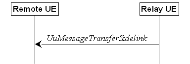
Figure 5.8.9.9.1-1: Uu message transfer in
sidelink
The purpose of this procedure is to
transfer Paging message and System Information from the L2 U2N Relay UE
to the L2 U2N Remote UE in RRC_IDLE/RRC_INACTIVE.
The L2 U2N Relay UE initiates the Uu
message transfer procedure when at least one of the following conditions is
met:
1> upon receiving Paging message related
to the connected L2 U2N Remote UE from network (including Paging message
within RRCReconfiguration message);
1> upon acquisition of the SIB(s)
requested by the connected L2 U2N Remote UE (as indicated in sl-RequestedSIB-List
in the RemoteUEInformationSidelink) or upon receiving the updated SIB(s)
from network which has been requested by the connected L2 U2N Remote UE;
1> upon acquisition of the posSIB(s)
requested by the connected L2 U2N Remote UE (as indicated in sl-RequestedPosSIB-List
in the RemoteUEInformationSidelink) or upon receiving the updated
posSIB(s) from network which have been requested by the connected L2 U2N Remote
UE;
1> upon unsolicited
SIB1 forwarding to the connected L2 U2N Remote UE or upon receiving the updated SIB1
from network;
For each associated L2 U2N Remote UE, the L2 U2N Relay UE shall
set the contents of UuMessageTransferSidelink message as follows:
1> include sl-PagingDelivery if the Paging
message received from network containing the ue-Identity of the L2 U2N
Remote UE;
1> include sl-SIB1-Delivery if any of
the conditions for initiating Uu message transfer procedure related to SIB1 are
met;
1> include sl-SystemInformationDelivery
if any of the conditions for initiating Uu message transfer procedure related
to System Information are met;
1> submit the UuMessageTransferSidelink message to lower layers for transmission.
NOTE: The L2 U2N Relay UE may perform
unsolicited forwarding of SIB1 to the L2 U2N Remote UE based on UE
implementation. A L2 U2N Remote UE configured with MP does not apply the SIB1
received from the L2 U2N Relay UE on the indirect path, if any.
Upon receiving the UuMessageTransferSidelink
message, the L2 U2N Remote UE shall:
1> if sl-PagingDelivery is included:
2> perform the paging reception procedure as specified
in clause 5.3.2.3;
1> if sl-SystemInformationDelivery and/or
sl-SIB1-Delivery is included:
2> perform the actions specified in clause
5.2.2.4.
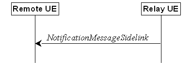
Figure 5.8.9.8.1-1: Notification message in
sidelink
This procedure is used by a U2N Relay UE to
send notification to the connected U2N Remote UE, or used by a L2 U2U Relay UE
to send notification to the L2
U2U Remote UE for an end-to-end PC5 connection when
condition(s) as specified in 5.8.9.10.2 is met for the hop between the L2 U2U
Relay UE and the peer L2 U2U Remote UE.
The Relay UE may initiate the procedure
when one of the following conditions is met:
1> if the UE is acting as U2N Relay UE:
2> upon Uu RLF as specified in 5.3.10;
2> upon reception of an
RRCReconfiguration including the reconfigurationWithSync;
2> upon cell reselection;
2> upon L2 U2N Relay UE's RRC connection
failure including RRC connection reject as specified in 5.3.3.5 and 5.3.13.10, and T300 expiry as specified
in 5.3.3.7, and RRC resume failure as specified in 5.3.13.5;
1> if the UE is acting as L2 U2U Relay UE:
2> upon detection of PC5 RLF for the hop
between the L2 U2U Relay UE and L2 U2U Remote UE as specified in 5.8.9.3;
2> upon PC5-RRC connection release for the
per-hop link between the L2 U2U Relay UE and L2 U2U Remote UE as specified in
5.8.9.5;
The Relay UE shall set the indication type
as follows:
1> if the UE is acting as U2N Relay UE:
2> if the UE initiates transmission of the NotificationMessageSidelink message due
to Uu RLF:
3> set the indicationType as relayUE-Uu-RLF;
2> else if the UE initiates transmission of the
NotificationMessageSidelink message due to reconfiguration with sync:
3> set the indicationType as relayUE-HO;
2> else if the UE initiates transmission of the
NotificationMessageSidelink message due to cell reselection:
3> set the indicationType as
relayUE-CellReselection;
2> if the UE initiates transmission of the NotificationMessageSidelink message due
to Uu RRC connection establishment/Resume failure:
3> set the indicationType as relayUE-Uu-RRC-Failure;
2> submit the NotificationMessageSidelink message to lower layers for
transmission.
1> if the UE is acting as L2 U2U Relay UE:
2> if the UE initiates transmission of the NotificationMessageSidelink message due
to PC5 RLF with L2 U2U Remote UE; or
2> if the UE initiates transmission of the NotificationMessageSidelink message due
to PC5-RRC connection release for the per-hop link between the L2 U2U Relay UE
and L2 U2U Remote UE:
3> set the sl-IndicationType as relayUE-PC5-RLF;
3> set the sl-DestinationIdentityRemoteUE
as the associated destination for L2 U2U Remote UE;
3> submit the
NotificationMessageSidelink message to lower layers for transmission;
Upon receiving the NotificationMessageSidelink, the Remote UE shall:
1> if the UE is acting as U2N Remote UE:
2> if the indicationType is included:
3> if the UE is L2 U2N Remote UE in
RRC_CONNECTED:
4> if MP is configured and MCG transmission
(i.e. direct path) is not suspended;
5> if the indicationType is relayUE-HO;
6> suspend indirect path transmission;
5> else:
6> initiate the indirect path failure information
procedure as specified in 5.7.3c to report indirect path failure;
4> else if T301 is not running, initiate the
RRC connection re-establishment procedure as specified in 5.3.7;
3> else (the UE is L3 U2N Remote UE, or L2 U2N
Remote UE in RRC_IDLE or RRC_INACTIVE):
4> if the PC5-RRC connection with the U2N Relay
UE is determined to be released:
5> indicate upper layers to trigger PC5 unicast
link release;
4> else (i.e., maintain
the PC5 RRC connection):
5> if the UE is L2 U2N Remote UE and the indicationType
is relayUE-HO or relayUE-CellReselection:
6> consider cell re-selection occurs;
NOTE 1: For L3 U2N Remote UE, or L2 U2N Remote UE
in RRC_IDLE or RRC_INACTIVE, it is up to Remote UE implementation whether to
release or keep the PC5 unicast link.
NOTE 2: The L2 U2N Remote
UE may ignore the NotificationMessageSidelink if it does not release the
PC5 unicast link in source side yet during an indirect-to-direct path switch,
i.e. T304 is running.
1> if the UE is acting as L2 U2U Remote UE:
2> if sl-IndicationType
is relayUE-PC5-RLF:
3> indicate PC5 RLF
received from L2 U2U Relay UE
to the upper layers for the indicated L2 U2U Remote UE based on the received sl-DestinationIdentityRemoteUE;
3> consider the end-to-end PC5 connection
failure for the end-to-end PC5 connection(s) over the per-hop PC5 link between
the L2 U2U Relay UE and the L2 U2U Remote UE identified
by sl-DestinationIdentityRemoteUE;
3> perform the
end-to-end PC5 connection failure related actions as
specified in 5.8.9.3a;
NOTE 3: It is up to the upper layers on whether
to trigger U2U Relay reselection and whether to keep or release the PC5 link
with the U2U Relay UE after the PC5 RLF indication received from U2U Relay UE.

Figure 5.8.9.11.1-1: Sidelink UE information
procedure
The purpose of this procedure is to
transfer the UE information between a Remote UE and a Relay UE in sidelink. The
L2 U2U Remote UE informs its end-to-end QoS information to its connected L2 U2U
Relay UE in the UEInformationRequestSidelink message, and the L2 U2U
Relay UE delivers the split QoS information of the first-hop to the Remote UE
in the UEInformationResponseSidelink message.
For initial information transfer (e.g. for
QoS split) or upon change in any of the information in the UEInformationRequestSidelink,
the UE shall set the contents of UEInformationRequestSidelink message as
follows and include all concerned information, irrespective of trigger
condition:
1> if the UE is acting as L2 U2U Remote UE:
2> set sl-E2E-QoS-InfoListPC5 to include
the end-to-end QoS profile(s) of the sidelink QoS flow(s) towards the peer L2 U2U Remote UE if configured by the upper
layer, and for each entry:
3> set sl-DestinationIdentityRemoteUE to
include the associated identity for peer L2 U2U Remote
UE;
3> set sl-E2E-SLRB-Index to include the associated end-to-end SLRB configuration index;
3> set sl-QoS-InfoList to
include the end-to-end QoS profile(s) of the sidelink QoS flow(s);
2> submit the UEInformationRequestSidelink
message to lower layers for transmission.
The UE shall perform the following actions
upon reception of the UEInformationRequestSidelink:
1> if the UE is acting as L2 U2U Relay UE:
2> perform QoS split
based on the sl-QoS-InfoList for each QoS flow to decide the split PDB
value for each PC5 hop;
2> set the contents of UEInformationResponseSidelink message as
follows:
3> set sl-SplitQoS-InfoListPC5 to include the split PDB value
for each QoS flow on the first PC5 hop between L2 U2U Relay UE and L2 U2U
Remote UE;
2> submit the UEInformationResponseSidelink
message to lower layers for transmission;
2> for each sl-E2E-SLRB-Index value included in the sl-E2E-QoS-InfoListPC5:
3> merge the split per-flow QoS on the second PC5 hop into a per-SLRB level QoS profile;
2> if the UE is in RRC_IDLE or RRC_INACTIVE or out of coverage:
3> derive the PC5 Relay
RLC channel configuration on
the second PC5 hop based on the
per-SLRB level QoS profile of this end-to-end sidelink DRB, as specified in 5.8.9.7.0;
3> (re)configure the
SRAP entity to map the end-to-end DRB with PC5 Relay RLC channel, if needed;
2> if the UE is in RRC_CONNECTED:
3> initiate sidelink UE
information procedure according to clause 5.8.3.2 to
report per-SLRB level QoS.
NOTE 1: It is left to Relay UE implementation on
how to split the PDB.
NOTE 2: For a L2 U2U Relay UE, how to merge the
split per-flow QoS on the second PC5 hop into a per-SLRB level QoS profile is
up to UE implementation.
The UE shall perform the following actions
upon reception of the UEInformationResponseSidelink:
1> if the UE is in RRC_CONNECTED:
2> initiate sidelink UE information procedure
according to clause 5.8.3.2 to report the split QoS
profile for the first PC5 hop;
1> else (UE in RRC_IDLE or RRC_INACTIVE or out of coverage):
2> for each sl-E2E-SLRB-Index value included in the sl-E2E-QoS-InfoListPC5 in UEInformationRequestSidelink:
3> merge the split per-flow QoS on the first PC5 hop into a per-SLRB level QoS profile;
3> derive the PC5 Relay RLC channel
configuration for the first PC5 hop based on the per-SLRB level QoS profile of this end-to-end
sidelink DRB, as specifed in 5.8.9.7.0;
3> (re)configure the SRAP entity to map the
end-to-end DRB with PC5 Relay RLC channel, if needed.
NOTE: For a L2 U2U Remote UE in RRC_IDLE or RRC_INACTIVE or out of coverage,
how to merge the split per-flow QoS on the first PC5 hop into a per-SLRB level
QoS profile is up to UE implementation.
The UE may configure the associated peer UE
to perform NR sidelink measurement and report on the corresponding PC5-RRC
connection in accordance with the NR sidelink measurement configuration for
unicast by RRCReconfigurationSidelink message.
The NR sidelink measurement configuration
includes the following parameters for a PC5-RRC
connection:
1. NR sidelink measurement objects: Object(s) on which the associated peer UE shall perform the NR
sidelink measurements.
- For NR sidelink measurement, a NR sidelink
measurement object indicates the NR sidelink frequency of reference signals to
be measured.
2. NR sidelink reporting configurations: NR sidelink measurement reporting configuration(s) where there can
be one or multiple NR sidelink reporting configurations per NR sidelink
measurement object. Each NR sidelink reporting configuration consists of the
following:
- Reporting criterion: The criterion that
triggers the UE to send a NR sidelink measurement report. This can either be
periodical or a single event description.
- RS type: The RS that the UE uses for NR
sidelink measurement results. In this release, only DMRS is supported for NR
sidelink measurement.
- Reporting format: The quantities that the UE
includes in the measurement report. In this release, only RSRP measurement is
supported.
3. NR sidelink measurement identities: A list of NR sidelink measurement identities where each NR sidelink
measurement identity links one NR sidelink measurement object with one NR
sidelink reporting configuration. By configuring multiple NR sidelink
measurement identities, it is possible to link more than one NR sidelink
measurement object to the same NR sidelink reporting configuration, as well as
to link more than one NR sidelink reporting configuration to the same NR
sidelink measurement object. The NR sidelink measurement identity is also included
in the NR sidelink measurement report that triggered the reporting, serving as
a reference to the network.
4. NR sidelink quantity configurations: The NR sidelink quantity configuration defines the NR sidelink
measurement filtering configuration used for all event evaluation and related
reporting, and for periodical reporting of that NR sidelink measurement. In
each configuration, different filter coefficients can be configured for
different NR sidelink measurement quantities.
Both UEs of the PC5-RRC connection
maintains a NR sidelink measurement object list, a NR sidelink reporting
configuration list, and a NR sidelink measurement identities list according to
signalling and procedures in this specification.
The UE shall:
1> if the received sl-MeasConfig
includes the sl-MeasObjectToRemoveList in the RRCReconfigurationSidelink:
2> perform the sidelink measurement object
removal procedure as specified in 5.8.10.2.4;
1> if the received sl-MeasConfig
includes the sl-MeasObjectToAddModList in the RRCReconfigurationSidelink:
2> perform the sidelink measurement object
addition/modification procedure as specified in 5.8.10.2.5;
1> if the received sl-MeasConfig
includes the sl-ReportConfigToRemoveList in the RRCReconfigurationSidelink:
2> perform the sidelink reporting configuration
removal procedure as specified in 5.8.10.2.6;
1> if the received sl-MeasConfig
includes the sl-ReportConfigToAddModList in the RRCReconfigurationSidelink:
2> perform the sidelink reporting configuration
addition/modification procedure as specified in 5.8.10.2.7;
1> if the received sl-MeasConfig
includes the sl-QuantityConfig in the RRCReconfigurationSidelink:
2> perform the sidelink quantity configuration
procedure as specified in 5.8.10.2.8;
1> if the received sl-MeasConfig
includes the sl-MeasIdToRemoveList in the RRCReconfigurationSidelink:
2> perform the sidelink measurement identity
removal procedure as specified in 5.8.10.2.2;
1> if the received sl-MeasConfig
includes the sl-MeasIdToAddModList in the RRCReconfigurationSidelink:
2> perform the sidelink measurement identity
addition/modification procedure as specified in 5.8.10.2.3;
The UE shall:
1> for each sl-MeasId included in the
received sl-MeasIdToRemoveList that is part of the current UE
configuration in VarMeasConfigSL:
2> remove the entry with the matching sl-MeasId
from the sl-MeasIdList within the VarMeasConfigSL;
2> remove the NR sidelink measurement reporting
entry for this sl-MeasId from the VarMeasReportListSL, if
included;
2> stop the periodical reporting timer and
reset the associated information (e.g. sl-TimeToTrigger) for this sl-MeasId.
NOTE: The UE does not consider the message as
erroneous if the sl-MeasIdToRemoveList includes any sl-MeasId
value that is not part of the current UE configuration.
The UE shall:
1> for each sl-MeasId included in the
received sl-MeasIdToAddModList:
2> if an entry with the matching sl-MeasId
exists in the sl-MeasIdList within the VarMeasConfigSL:
3> replace the entry with the value received
for this sl-MeasId;
2> else:
3> add a new entry for this sl-MeasId
within the VarMeasConfigSL;
2> remove the measurement reporting entry for
this sl-MeasId from the VarMeasReportListSL, if included;
2> stop the periodical reporting timer and
reset the associated information (e.g. sl-TimeToTrigger) for this sl-MeasId;
The UE shall:
1> for each sl-MeasObjectId included in the
received sl-MeasObjectToRemoveList that is part of sl-MeasObjectList in
VarMeasConfigSL:
2> remove the entry with the matching sl-MeasObjectId
from the sl-MeasObjectList within the VarMeasConfigSL;
2> remove all sl-MeasId associated with
this sl-MeasObjectId from the sl-MeasIdList within the VarMeasConfigSL,
if any;
2> if a sl-MeasId is removed from the sl-MeasIdList:
3> remove the measurement reporting entry for
this sl-MeasId from the VarMeasReportListSL, if included;
3> stop the periodical reporting timer and
reset the associated information (e.g. sl-TimeToTrigger) for this sl-MeasId.
NOTE: The UE does not consider the message as
erroneous if the sl-MeasObjectToRemoveList includes any sl-MeasObjectId
value that is not part of the current UE configuration.
The UE shall:
1> for each sl-MeasObjectId included in
the received sl-MeasObjectToAddModList:
2> if an entry with the matching sl-MeasObjectId
exists in the sl-MeasObjectList within the VarMeasConfigSL, for
this entry:
3> for each sl-MeasId associated with
this sl-MeasObjectId included in the sl-MeasIdList within the VarMeasConfigSL,
if any:
4> remove the measurement reporting entry for
this sl-MeasId from the VarMeasReportListSL, if included;
4> stop the periodical reporting timer and
reset the associated information (e.g. sl-TimeToTrigger) for this sl-MeasId;
3> reconfigure the entry with the value
received for this sl-MeasObject;
2> else:
3> add a new entry for the received sl-MeasObject
to the sl-MeasObjectList within VarMeasConfigSL.
The UE shall:
1> for each sl-ReportConfigId included
in the received sl-ReportConfigToRemoveList that is part of the current
UE configuration in VarMeasConfigSL:
2> remove the entry with the matching sl-ReportConfigId
from the sl-ReportConfigList within the VarMeasConfigSL;
2> remove all sl-MeasId associated with
the sl-ReportConfigId from the sl-MeasIdList within the VarMeasConfigSL,
if any;
2> if a sl-MeasId is removed from the sl-MeasIdList:
3> remove the measurement reporting entry for
this sl-MeasId from the VarMeasReportListSL, if included;
3> stop the periodical reporting timer and
reset the associated information (e.g. sl-TimeToTrigger) for this sl-MeasId.
NOTE: The UE does not consider the message as
erroneous if the sl-ReportConfigToRemoveList includes any sl-ReportConfigId
value that is not part of the current UE configuration.
The UE shall:
1> for each sl-ReportConfigId included in the
received sl-ReportConfigToAddModList:
2> if an entry with the matching sl-ReportConfigId
exists in the sl-ReportConfigList within the VarMeasConfigSL, for
this entry:
3> reconfigure the entry with the value
received for this sl-ReportConfig;
3> for each sl-MeasId associated with
this sl-ReportConfigId included in the sl-MeasIdList within the VarMeasConfigSL,
if any:
4> remove the measurement reporting entry for
this sl-MeasId from the VarMeasReportListSL, if included;
4> stop the periodical reporting timer and
reset the associated information (e.g. sl-TimeToTrigger) for this sl-MeasId;
2> else:
3> add a new entry for the received sl-ReportConfig
to the sl-ReportConfigList within the VarMeasConfigSL.
The UE shall:
1> for each received sl-QuantityConfig:
2> set the corresponding parameter(s) in sl-QuantityConfig
within VarMeasConfigSL to the value of the received sl-QuantityConfig
parameter(s);
1> for each sl-MeasId included in the sl-MeasIdList
within VarMeasConfigSL:
2> remove the measurement reporting entry for
this sl-MeasId from the VarMeasReportListSL, if included;
2> stop the periodical reporting timer and
reset the associated information (e.g. sl-TimeToTrigger) for this sl-MeasId.
A UE shall derive NR sidelink measurement
results by measuring one or multiple DMRS associated per PC5-RRC connection as
configured by the peer UE associated, as described in 5.8.10.3.2. For all NR
sidelink measurement results the UE applies the layer 3 filtering as specified
in clause 5.5.3.2, before using the measured results for evaluation of
reporting criteria and measurement reporting. In this release, only NR sidelink
RSRP can be configured as trigger quantity and reporting quantity.
The UE shall:
1> for each sl-MeasId included in the sl-MeasIdList
within VarMeasConfigSL:
2> if the sl-MeasObject is associated to
NR sidelink and the sl-RS-Type is set to dmrs:
3> derive the layer 3 filtered NR sidelink
measurement result based on PSSCH DMRS for the trigger quantity and each measurement quantity
indicated in sl-ReportQuantity using parameters from the associated sl-MeasObject,
as described in 5.8.10.3.2.
2> perform the evaluation of reporting criteria
as specified in 5.8.10.4.
The UE may be configured by the peer UE
associated to derive NR sidelink RSRP measurement results per PC5-RRC
connection associated to the NR sidelink measurement objects based on
parameters configured in the sl-MeasObject and in the sl-ReportConfig.
The UE shall:
1> for each NR sidelink measurement quantity to
be derived based on NR sidelink DMRS/SL-PRS:
2> derive the corresponding measurement of NR
sidelink frequency indicated quantity based on PSSCH DMRS/SL-PRS as described in TS 38.215 [9] in the concerned sl-MeasObject;
2> apply layer 3 filtering as described in
5.5.3.2;
The UE shall:
1> for each sl-MeasId included in the sl-MeasIdList
within VarMeasConfigSL:
2> if the sl-ReportType is set to sl-EventTriggered
and if the entry condition applicable for this event, i.e. the event
corresponding with the sl-EventId of the corresponding sl-ReportConfig
within VarMeasConfigSL, is fulfilled for NR sidelink frequency for all
NR sidelink measurements after layer 3 filtering taken during sl-TimeToTrigger
defined for this event within the VarMeasConfigSL, while the VarMeasReportListSL
does not include a NR sidelink measurement reporting entry for this sl-MeasId
(a first NR sidelink frequency triggers the event):
3> include a NR sidelink measurement reporting
entry within the VarMeasReportListSL for this sl-MeasId;
3> set the sl-NumberOfReportsSent
defined within the VarMeasReportListSL for this sl-MeasId to 0;
3> include the concerned NR sidelink frequency
in the sl-FrequencyTriggeredList defined within the VarMeasReportListSL
for this sl-MeasId;
3> initiate the NR sidelink measurement
reporting procedure, as specified in 5.8.10.5;
2> else if the sl-ReportType is set to sl-EventTriggered
and if the entry condition applicable for this event, i.e. the event
corresponding with the sl-EventId of the corresponding sl-ReportConfig
within VarMeasConfigSL, is fulfilled for NR sidelink frequency not
included in the sl-FrequencyTriggeredList for all NR sidelink
measurements after layer 3 filtering taken during sl-TimeToTrigger
defined for this event within the VarMeasConfigSL (a subsequent NR
sidelink frequency triggers the event):
3> set the sl-NumberOfReportsSent
defined within the VarMeasReportListSL for this sl-MeasId to 0;
3> include the concerned NR sidelink frequency
in the sl-FrequencyTriggeredList defined within the VarMeasReportListSL
for this sl-MeasId;
3> initiate the NR sidelink measurement
reporting procedure, as specified in 5.8.10.5;
2> else if the sl-ReportType is set to sl-EventTriggered
and if the leaving condition applicable for this event is fulfilled for NR
sidelink frequency included in the sl-FrequencyTriggeredList defined
within the VarMeasReportListSL for this sl-MeasId for all NR
sidelink measurements after layer 3 filtering taken during sl-TimeToTrigger defined
within the VarMeasConfigSL for this event:
3> remove the concerned NR sidelink frequency
in the sl-FrequencyTriggeredList defined within the VarMeasReportListSL
for this sl-MeasId;
3> if sl-ReportOnLeave is set to true for the corresponding reporting
configuration:
4> initiate the NR sidelink measurement
reporting procedure, as specified in 5.8.10.5;
3> if the sl-FrequencyTriggeredList
defined within the VarMeasReportListSL for this sl-MeasId is
empty:
4> remove the NR sidelink measurement reporting
entry within the VarMeasReportListSL for this sl-MeasId;
4> stop the periodical reporting timer for this
sl-MeasId, if running;
2> if sl-ReportType is set to sl-Periodical
and if a (first) NR sidelink measurement result is available:
3> include a NR sidelink measurement reporting
entry within the VarMeasReportListSL for this sl-MeasId;
3> set the sl-NumberOfReportsSent
defined within the VarMeasReportListSL for this sl-MeasId to 0;
3> initiate the NR sidelink measurement
reporting procedure, as specified in 5.8.10.5, immediately after the quantity
to be reported becomes available for the NR sidelink frequency:
2> upon expiry of the periodical reporting
timer for this sl-MeasId:
3> initiate the NR sidelink measurement
reporting procedure, as specified in 5.8.10.5.
The UE shall:
1> consider the entering condition for this
event to be satisfied when condition S1-1, as specified below, is fulfilled;
1> consider the leaving condition for this
event to be satisfied when condition S1-2, as specified below, is fulfilled;
1> for this NR sidelink measurement, consider
the NR sidelink frequency corresponding to the associated sl-MeasObject
associated with this event.
Inequality S1-1
(Entering condition)
Ms – Hys > Thresh
Inequality S1-2
(Leaving condition)
Ms + Hys < Thresh
The variables in the formula are defined as
follows:
Ms is the NR
sidelink measurement result of the NR sidelink frequency, not taking into
account any offsets.
Hys is the
hysteresis parameter for this event (i.e. sl-Hysteresis as defined
within sl-ReportConfig for this event).
Thresh is
the threshold parameter for this event (i.e. s1-Threshold as defined
within sl-ReportConfig for this event).
Ms is
expressed in dBm in case of RSRP.
Hys is
expressed in dB.
Thresh
is expressed in the
same unit as Ms.
The UE shall:
1> consider the entering condition for this
event to be satisfied when condition S2-1, as specified below, is fulfilled;
1> consider the leaving condition for this
event to be satisfied when condition S2-2, as specified below, is fulfilled;
1> for this NR sidelink measurement, consider
the NR sidelink frequency indicated by the sl-MeasObject associated to
this event.
Inequality S2-1
(Entering condition)
Ms + Hys < Thresh
Inequality S2-2
(Leaving condition)
Ms – Hys > Thresh
The variables in the formula are defined as
follows:
Ms is the NR
sidelink measurement result of the NR sidelink frequency, not taking into
account any offsets.
Hys is the
hysteresis parameter for this event (i.e. sl-Hysteresis as defined
within sl-ReportConfig for this event).
Thresh is
the threshold parameter for this event (i.e. s2-Threshold as defined
within sl-ReportConfig for this event).
Ms is
expressed in dBm in case of RSRP.
Hys is
expressed in dB.
Thresh
is expressed in the
same unit as Ms.

Figure 5.8.10.5.1-1: NR sidelink measurement
reporting
The purpose of this procedure is to
transfer measurement results from the UE to the peer UE associated.
For the sl-MeasId for which the NR
sidelink measurement reporting procedure was triggered, the UE shall set the sl-MeasResults
within the MeasurementReportSidelink message as follows:
1> set the sl-MeasId to the measurement
identity that triggered the NR sidelink measurement reporting;
1> if the sl-ReportConfig associated
with the sl-MeasId that triggered the NR sidelink measurement reporting
is set to sl-EventTriggered or sl-Periodical:
2> if the sl-RS-Type within sl-ReportConfig is set to dmrs:
3> set sl-ResultDMRS within sl-MeasResult
to include the NR sidelink DMRS based quantity indicated in the sl-ReportQuantity
within the concerned sl-ReportConfig;
2> if the sl-RS-Type within sl-ReportConfig is set to sl-prs:
3> set sl-Result-SL-PRS within sl-MeasResult
to include the NR SL-PRS based quantity indicated in the sl-ReportQuantity
within the concerned sl-ReportConfig;
1> increment the sl-NumberOfReportsSent
as defined within the VarMeasReportListSL for this sl-MeasId by
1;
1> stop the periodical reporting timer, if
running;
1> if the sl-NumberOfReportsSent as
defined within the VarMeasReportListSL for this sl-MeasId is less
than the sl-ReportAmount as defined within the corresponding sl-ReportConfig
for this sl-MeasId:
2> start the periodical reporting timer with
the value of sl-ReportInterval as defined within the corresponding sl-ReportConfig
for this sl-MeasId;
1> else:
2> if the sl-ReportType is set to sl-Periodical:
3> remove the entry within the VarMeasReportListSL
for this sl-MeasId;
3> remove this sl-MeasId from the sl-MeasIdList
within VarMeasConfigSL;
1> submit the MeasurementReportSidelink
message to lower layers for transmission, upon which the procedure ends.
5.8.11 Zone identity calculation
The UE shall determine an identity of the
zone (i.e. Zone_id) in which it is located using the following formulae, if sl-ZoneConfig
is configured:
x1= Floor (x / L) Mod 64;
y1= Floor (y / L) Mod 64;
Zone_id = y1
* 64 + x1.
The parameters in the formulae are defined
as follows:
L is the value of sl-ZoneLength
included in sl-ZoneConfig;
x is the geodesic
distance in longitude between UE's current location and geographical
coordinates (0, 0) according to WGS84 model [58] and it is expressed in meters;
y is the geodesic
distance in latitude between UE's current location and geographical coordinates
(0, 0) according to WGS84 model [58] and it is expressed in meters.
NOTE: How the calculated zone_id is used is
specified in TS 38.321 [3].
When the UE selects GNSS as the
synchronization reference source, the DFN, the subframe number within a frame
and slot number within a frame used for NR sidelink communication/discovery are
derived from the current UTC time, by the following formulae:
DFN= Floor (0.1*(Tcurrent –Tref–OffsetDFN)) mod 1024
SubframeNumber= Floor (Tcurrent –Tref–OffsetDFN) mod 10
SlotNumber= Floor ((Tcurrent –Tref–OffsetDFN)*2μ)
mod (10*2μ)
Where:
Tcurrent is
the current UTC time obtained from GNSS. This value is expressed in
milliseconds;
Tref is the
reference UTC time 00:00:00 on Gregorian calendar date 1 January, 1900 (midnight between Thursday, December 31, 1899
and Friday, January 1, 1900). This value is
expressed in milliseconds;
OffsetDFN is
the value sl-OffsetDFN if configured, otherwise it is zero. This value
is expressed in milliseconds.
μ=0/1/2/3 corresponding to the 15/30/60/120
kHz of SCS for SL, respectively.
NOTE 1: In case of leap second change event, how
UE obtains the scheduled time of leap second change to adjust Tcurrent
correspondingly is left to UE implementation. How UE handles to avoid the
sudden discontinuity of DFN is left to UE implementation.
NOTE 2: Void.
The purpose of this procedure is to perform
NR sidelink discovery as
specified in TS 23.304 [65].
5.8.13.2 NR sidelink discovery monitoring
A UE capable of NR sidelink discovery that is configured by upper layers to monitor NR
sidelink discovery messages shall:
1> if the frequency used for NR sidelink
discovery is included in sl-FreqInfoToAddModList in RRCReconfiguration
message and sl-DiscConfig is included in RRCReconfiguration; or
if the frequency used for NR sidelink discovery is included in sl-FreqInfoList
included in SIB12 and sl-DiscConfigCommon is included in SIB12:
2> if the UE is configured with sl-DiscRxPool
for NR sidelink discovery
reception included in RRCReconfiguration message with reconfigurationWithSync
(i.e. handover):
3> configure lower layers to monitor sidelink
control information and the corresponding data using the resource pool
indicated by sl-DiscRxPool for NR sidelink discovery reception in RRCReconfiguration;
2> else if the UE is configured with sl-RxPool
for NR sidelink discovery
reception included in RRCReconfiguration message with reconfigurationWithSync
(i.e. handover):
3> configure lower layers to monitor sidelink
control information and the corresponding data using the resource pool
indicated by sl-RxPool for NR sidelink discovery reception in RRCReconfiguration;
2> else if the cell chosen for NR sidelink
discovery reception provides SIB12:
3> if sl-DiscRxPool for NR sidelink discovery reception is included in SIB12:
4> configure lower layers to monitor sidelink
control information and the corresponding data using the resource pool
indicated by sl-DiscRxPool for NR sidelink discovery reception in SIB12;
3> else if sl-RxPool for NR sidelink discovery reception is included in SIB12:
4> configure lower layers to monitor sidelink
control information and the corresponding data using the resource pool
indicated by sl-RxPool for NR sidelink discovery reception in SIB12;
1> else:
2> if out of coverage on the concerned
frequency for NR sidelink discovery:
3> if sl-DiscRxPool was preconfigured:
4> configure lower layers to monitor sidelink
control information and the corresponding data using the resource pool that was
preconfigured by sl-DiscRxPool for NR sidelink discovery reception in SL-PreconfigurationNR, as defined
in clause 9.3;
3> else:
4> configure lower layers to monitor sidelink
control information and the corresponding data using the resource pool that was
preconfigured by sl-RxPool for NR sidelink discovery reception in SL-PreconfigurationNR, as defined
in clause 9.3;
NOTE: If sl-DiscRxPool and sl-RxPool
are both included in SIB12 or preconfigured, it is up to UE implementation
whether to monitor sidelink control information and the corresponding data
using the resource pool indicated by sl-RxPool for NR sidelink discovery
reception.
5.8.13.3 NR sidelink discovery transmission
A UE capable of NR sidelink discovery that is configured by upper layer to transmit NR
sidelink discovery message shall:
1> if the frequency used for NR sidelink
discovery is included in sl-FreqInfoToAddModList in sl-ConfigDedicatedNR
within RRCReconfiguration message; or if the frequency used for NR
sidelink discovery is included in sl-FreqInfoList within SIB12:
2> if the UE is in RRC_CONNECTED and uses the
frequency included in sl-ConfigDedicatedNR within RRCReconfiguration
message:
3> if the UE is acting as NR sidelink U2N Relay
UE and sl-DiscConfig is
included in RRCReconfiguration, and if the NR sidelink U2N Relay UE
threshold conditions as specified in 5.8.14.2 are met based on sl-RelayUE-Config;
or
3> if the UE is selecting NR sidelink U2N Relay
UE / has a selected NR sidelink U2N Relay UE/ configured with measurement
object associated to L2 U2N Relay UEs and sl-DiscConfig is included in RRCReconfiguration, and
if the NR sidelink U2N Remote UE threshold conditions as specified in 5.8.15.2
are met based on sl-RemoteUE-Config; or
3> if the UE is selecting NR sidelink U2U Relay
UE / has a selected NR sidelink U2U Relay UE and sl-DiscConfig is
included in RRCReconfiguration, and if the NR sidelink U2U Remote UE
threshold conditions associated with the peer NR Sidelink U2U Remote UE as
specified in 5.8.17.2 are met based on sl-RemoteUE-ConfigU2U; or
3> if the UE acting as
Target Remote UE is performing U2U Relay Discovery with Model B and sl-DiscConfig
is included in RRCReconfiguration, and if the NR sidelink U2U Remote UE
threshold conditions associated with the NR sidelink U2U Relay UE as specified
in 5.8.17.2 are met based on sl-RemoteUE-ConfigU2U; or
3> if the UE acting as U2U Relay UE is
performing U2U Relay Discovery with Model A as specified in TS 23.304[65], and neighbour UEs in discovery message to
be transmitted meet the threshold conditions as specified in 5.8.16.3; or
3> if the UE acting as U2U Relay UE is sending
Discovery Response message with Model B as specified in TS 23.304[65]; or
3> if the UE acting as U2U Relay UE is sending
Discovery Solicitation message with Model B as specified in TS 23.304[65] and sl-DiscConfig is included in RRCReconfiguration, and if the NR sidelink U2U Relay UE threshold conditions as
specified in 5.8.16.2 are met based on sl-RelayUE-ConfigU2U;
or
NOTE 1: For U2U Relay UE and Target Remote UE, it
can be up to UE implementation on cross-layer interaction for the AS layer
condition check for discovery message forwarding.
3> if the UE is performing NR sidelink
non-relay discovery:
4> if the UE is configured with sl-ScheduledConfig:
5> if T310 for MCG or T311 is running; and if sl-TxPoolExceptional
is included in sl-FreqInfoList for the concerned frequency in SIB12
or included in sl-ConfigDedicatedNR in RRCReconfiguration; or
5> if T301 is running and the cell on which the
UE initiated RRC connection re-establishment provides SIB12 including sl-TxPoolExceptional
for the concerned frequency; or
5> if T304 for MCG is running and the UE is
configured with sl-TxPoolExceptional included in sl-ConfigDedicatedNR
for the concerned frequency in RRCReconfiguration:
6> configure lower layers to perform the
sidelink resource allocation mode 2 based on random selection using the
resource pool indicated by sl-TxPoolExceptional as defined in TS 38.321
[3] for NR sidelink discovery
transmission;
5> else:
6> configure lower layers to perform the
sidelink resource allocation mode 1 using the resource pool indicated by sl-DiscTxPoolScheduling
or sl-TxPoolScheduling for NR sidelink discovery transmission on the concerned frequency in RRCReconfiguration;
5> if T311 is running, configure the lower
layers to release the resources indicated by rrc-ConfiguredSidelinkGrant (if
any);
4> if the UE is configured with
sl-UE-SelectedConfig:
5> if the sl-DiscTxPoolSelected for NR sidelink discovery transmission on the concerned frequency is
included in the sl-ConfigDedicatedNR within RRCReconfiguration, and if a result of full/partial sensing,
if selected and is allowed by sl-AllowedResourceSelectionConfig, on the
resources configured in sl-DiscTxPoolSelected for
NR sidelink discovery transmission on the concerned frequency included in sl-ConfigDedicatedNR within
RRCReconfiguration is not available in accordance with TS 38.214 [19]; or
5> if the sl-DiscTxPoolSelected for NR sidelink discovery transmission on the concerned frequency is
not included in the sl-ConfigDedicatedNR within RRCReconfiguration, and a result of full/partial sensing,
if selected and is allowed by sl-AllowedResourceSelectionConfig, on the
resources configured in sl-TxPoolSelectedNormal for NR sidelink discovery transmission on the concerned frequency included in sl-ConfigDedicatedNR within
RRCReconfiguration is not available in accordance with TS 38.214 [19];
6> if sl-TxPoolExceptional for the
concerned frequency is included in RRCReconfiguration; or
6> if the PCell provides SIB12 including
sl-TxPoolExceptional in sl-FreqInfoList for the concerned frequency:
7> configure lower layers to perform the
sidelink resource allocation mode 2 based on random selection using the
resource pool indicated by sl-TxPoolExceptional as defined in TS 38.321
[3] for NR sidelink discovery
transmission;
5> else, if the sl-DiscTxPoolSelected for NR sidelink discovery transmission on the concerned frequency is
included in the sl-ConfigDedicatedNR within RRCReconfiguration:
6> configure lower layers to perform the
sidelink resource allocation mode 2 based on resource selection operation
according to sl-AllowedResourceSelectionConfig (as defined in TS 38.321
[3] and TS 38.214 [19]) using the pools of resources indicated by sl-DiscTxPoolSelected
for NR sidelink discovery transmission on the
concerned frequency in RRCReconfiguration;
5> else, if the sl-TxPoolSelectedNormal for NR sidelink discovery transmission on the concerned frequency is
included in the sl-ConfigDedicatedNR within RRCReconfiguration:
6> configure lower layers to perform the
sidelink resource allocation mode 2 based on resource selection operation
according to sl-AllowedResourceSelectionConfig (as defined in TS 38.321
[3] and TS 38.214 [19]) using the pools of resources indicated by
sl-TxPoolSelectedNormal for NR sidelink discovery
transmission on the concerned frequency in RRCReconfiguration;
2> else if the cell chosen for NR sidelink
discovery transmission provides SIB12:
3> if the UE is acting as NR sidelink U2N Relay
UE and sl-DiscConfigCommon is included in SIB12, and if the NR
sidelink U2N Relay UE threshold conditions as specified in 5.8.14.2 are met
based on sl-RelayUE-ConfigCommon in SIB12; or
3> if the UE is selecting NR sidelink U2N Relay
UE / has a selected NR sidelink U2N Relay UE and sl-DiscConfigCommon is
included in SIB12, and if the NR sidelink U2N Remote UE threshold
conditions as specified in 5.8.15.2 are met based on sl-RemoteUE-ConfigCommon
in SIB12; or
3> if the UE is selecting NR sidelink U2U Relay
UE / has a selected NR sidelink U2U Relay UE and sl-DiscConfigCommon is
included in SIB12, and if the NR sidelink U2U Remote UE threshold
conditions associated with the peer NR Sidelink U2U Remote UE as specified in
5.8.17.2 are met based on sl-RemoteUE-ConfigCommonU2U in SIB12;
or
3> if the UE acting as
Target Remote UE is performing U2U Relay Discovery with Model B and if the
NR sidelink U2U Remote UE threshold conditions associated with the NR sidelink
U2U Relay UE as specified in 5.8.17.2 are met based on sl-RemoteUE-ConfigCommonU2U
in SIB12; or
3> if the UE acting as U2U Relay UE is
performing U2U Relay Discovery with Model A as specified in TS 23.304[65], and neighbor UEs in discovery message to be transmitted meet the
threshold conditions as specified in 5.8.16.3; or
3> if the UE acting as U2U Relay UE is sending
Discovery Response message with Model B as specified in TS 23.304[65]; or
3> if the UE acting as U2U Relay UE is sending
Discovery Solicitation message with
Model B as specified in TS 23.304[65] and if the NR sidelink U2U Relay UE
threshold conditions as specified in 5.8.16.2 are met based on sl-RelayUE-ConfigCommonU2U
in SIB12; or
3> if the UE is performing NR sidelink
non-relay discovery:
4> if SIB12 includes sl-DiscTxPoolSelected
for NR sidelink discovery transmission on the
concerned frequency, and a result of full/partial
sensing, if selected and is allowed by sl-AllowedResourceSelectionConfig,
on the resources configured in the sl-DiscTxPoolSelected for NR sidelink discovery transmission is
available in accordance with TS 38.214 [19] or random selection, if allowed by sl-AllowedResourceSelectionConfig,
is selected:
5> configure lower layers to perform the
sidelink resource allocation mode 2 based on resource selection operation
according to sl-AllowedResourceSelectionConfig using the pools of
resources indicated by sl-DiscTxPoolSelected for
NR sidelink discovery transmission on the concerned frequency in SIB12 as defined in TS 38.321 [3];
4> else if SIB12 includes sl-TxPoolSelectedNormal
for NR sidelink discovery transmission on the
concerned frequency, and a result of full/partial
sensing, if selected and is allowed by sl-AllowedResourceSelectionConfig,
on the resources configured in the sl-TxPoolSelectedNormal for NR sidelink discovery transmission is
available in accordance with TS 38.214 [19] or random selection, if allowed by sl-AllowedResourceSelectionConfig,
is selected:
5> configure lower layers to perform the
sidelink resource allocation mode 2 based on resource selection operation
according to sl-AllowedResourceSelectionConfig using the pools of
resources indicated by sl-TxPoolSelectedNormal for
NR sidelink discovery transmission on the concerned frequency in SIB12 as defined in TS 38.321 [3];
4> else if SIB12 includes sl-TxPoolExceptional
for the concerned frequency:
5> from the moment the UE initiates RRC
connection establishment or RRC connection resume, until receiving an RRCReconfiguration
including sl-ConfigDedicatedNR, or receiving an RRCRelease or an RRCReject;
or
5> if a result of full/partial sensing, if
selected and is allowed by sl-AllowedResourceSelectionConfig, on the
resources configured in sl-DiscTxPoolSelected for
NR sidelink discovery transmission on the concerned frequency in SIB12 is not available in accordance with TS 38.214 [19];
or
5> if sl-DiscTxPoolSelected for NR sidelink discovery transmission on the concerned frequency is not included in SIB12 and if a result of full/partial
sensing, if selected and is allowed by sl-AllowedResourceSelectionConfig,
on the resources configured in sl-TxPoolSelectedNormal for NR sidelink discovery transmission on the concerned frequency in SIB12 is not available in accordance with TS 38.214 [19]:
6> configure lower layers to perform the
sidelink resource allocation mode 2 based on random selection (as defined in TS
38.321 [3]) using one of the pools of resources indicated by sl-TxPoolExceptional
for NR sidelink discovery
transmission on the concerned frequency;
1> else if out of coverage
on the concerned frequency for NR sidelink discovery:
2> if the UE is acting as L3 U2N Relay UE; or
2> if the UE is selecting NR sidelink U2N Relay
UE / has a selected NR sidelink U2N Relay UE and if the NR sidelink U2N Remote
UE threshold conditions as specified in 5.8.15.2 are met based on sl-PreconfigDiscConfig
in SidelinkPreconfigNR; or
2> if the UE is selecting NR sidelink U2U Relay
UE / has a selected NR sidelink U2U Relay UE and if the NR sidelink U2U Remote
UE threshold conditions associated with the peer NR sidelink U2U Remote UE as
specified in 5.8.17.2 are met based on sl-RemoteUE-PreconfigU2U in SidelinkPreconfigNR;
or
2> if the UE acting as Target Remote UE is
performing U2U Relay Discovery with Model B and if the NR sidelink U2U Remote
UE threshold conditions associated with the NR sidelink U2U Relay UE as
specified in 5.8.17.2 are met based on sl-RemoteUE-PreconfigU2U in SidelinkPreconfigNR;
or
2> if the UE acting as
U2U Relay UE is performing U2U Relay Discovery with Model A as specified in TS
23.304[65], and neighbor UEs in discovery message to be transmitted meet the
threshold conditions as specified in 5.8.16.3; or
2> if the UE acting as U2U Relay UE is sending
Discovery Response message with Model B as specified in TS 23.304[65]; or
2> if the UE acting as U2U Relay UE is sending Discovery Solicitation
message with Model B as specified in TS 23.304[65] and if the NR sidelink U2U
Relay UE threshold conditions as specified in 5.8.16.2 are met based on sl-RelayUE-PreconfigU2U
in SidelinkPreconfigNR; or
2> if the UE is performing NR sidelink
non-relay discovery:
3> configure lower layers to perform the
sidelink resource allocation mode 2 based on resource selection operation
according to sl-AllowedResourceSelectionConfig (as defined in TS 38.321
[3] and TS 38.214 [19]) using the pools of resources indicated in sl-DiscTxPoolSelected
or sl-TxPoolSelectedNormal for NR sidelink
discovery transmission on the concerned frequency in SidelinkPreconfigNR.
NOTE 2: It is up to UE implementation to
determine, in accordance with TS 38.321[3], which resource pool to use if
multiple resource pools are configured, and which resource allocation scheme is
used in the AS based on UE capability (for a UE in RRC_IDLE/RRC_INACTIVE) and
the allowed resource schemes sl-AllowedResourceSelectionConfig in the
resource pool configuration.
This procedure is used by a UE supporting
NR sidelink U2N Relay UE operation configured by upper layers to transmit NR
sidelink discovery messages to evaluate AS layer conditions.
5.8.14.2 NR
sidelink U2N Relay UE threshold conditions
A UE capable of NR sidelink U2N Relay UE
operation shall:
1> if the threshold conditions specified in
this clause were previously not met:
2> if threshHighRelay is not configured;
or the RSRP measurement of the PCell, or the cell on which the UE camps, is
below threshHighRelay by hystMaxRelay if configured; and
2> if threshLowRelay is not configured;
or the RSRP measurement of the PCell, or the cell on which the UE camps, is
above threshLowRelay by hystMinRelay if configured:
3> consider the threshold conditions to be met
(entry);
1> else:
2> if the RSRP measurement of the PCell, or the
cell on which the UE camps, is above threshHighRelay if configured; or
2> if the RSRP measurement of the PCell, or the
cell on which the UE camps, is below threshLowRelay if configured;
3> consider the threshold conditions not to be
met (leave);
This procedure is used by a UE supporting
NR sidelink U2N Remote UE operation configured by upper layers to transmit NR
sidelink discovery message to evaluate AS layer conditions. The procedure is
also used to perform selection and reselection of NR sidelink U2N Relay UE.
A UE capable of NR sidelink U2N Remote UE
operation shall:
1> if the threshold conditions specified in
this clause were previously not
met:
2> if threshHighRemote is not
configured; or the RSRP measurement of the PCell, or the cell on which the UE
camps, is below threshHighRemote by hystMaxRemote if configured,
or
2> if the UE has no serving cell:
3> consider the threshold conditions to be met
(entry);
1> else:
2> if the RSRP measurement of the PCell, or the
cell on which the UE camps, is above threshHighRemote if configured:
3> consider the threshold conditions not to be
met (leave);
The L2 U2N Remote UE not configured with MP
considers the cell indicated by sl-ServingCellInfo in the SL-AccessInfo-L2U2N-r17
received from the connected L2 U2N Relay UE as the PCell/camping cell.
A UE capable of NR sidelink U2N Remote UE
operation that is configured by upper layers to search for a NR sidelink U2N
Relay UE shall:
1> if the UE has no serving cell; or
1> if the RSRP measurement of the cell on which
the UE camps (for L2 and L3 U2N Remote UE in RRC_IDLE or RRC_INACTIVE)/ the
PCell (for L3 U2N Remote UE in RRC_CONNECTED) is below threshHighRemote within
sl-RemoteUE-ConfigCommon/sl-RemoteUE-Config:
2> if the UE does not have a selected NR
sidelink U2N Relay UE; or
2> if the UE has a selected NR sidelink U2N
Relay UE, and SL-RSRP of the currently selected NR sidelink U2N Relay UE is
available and is below sl-RSRP-Thresh; or
2> if the UE has a selected NR sidelink U2N
Relay UE, and SL-RSRP of the currently selected NR sidelink U2N Relay UE is not
available, and SD-RSRP of the currently selected U2N Relay UE is below sl-RSRP-Thresh;
or
NOTE 1: U2N Remote UE uses SL-RSRP measurements
for relay reselection trigger evaluation when there is data transmission from
U2N Relay UE to U2N Remote UE, and it is left to UE implementation whether to
use SL-RSRP or SD-RSRP for relay reselection trigger evaluation in case of no
data transmission from U2N Relay UE to U2N Remote UE. If SD-RSRP is used, the
discovery procedure will be performed between the U2N Remote UE and the
selected U2N Relay UE.
2> if the UE has a selected NR sidelink U2N
Relay UE, and upper layers indicate not to use the currently selected NR
sidelink U2N Relay UE; or
2> if the UE has a selected NR sidelink U2N
Relay UE, and upper layers request the release of the PC5-RRC connection; or
2> if the UE has a selected NR sidelink U2N
Relay UE, and sidelink radio link failure is detected on the PC5-RRC connection
with the current U2N Relay UE as specified in clause 5.8.9.3:
3> perform NR sidelink discovery procedure as
specified in clause 5.8.13 in order to search for candidate NR sidelink U2N
Relay UEs:
4> when evaluating the one or more detected NR
sidelink U2N Relay UEs, apply layer 3 filtering as specified in 5.5.3.2 across
measurements that concern the same U2N Relay UE ID and using the sl-FilterCoefficientRSRP
in SIB12 (if in RRC_IDLE/INACTIVE), the sl-FilterCoefficientRSRP in sl-ConfigDedicatedNR
(if in RRC_CONNECTED) or the sl-FilterCoefficientRSRP
in SidelinkPreconfigNR (out of coverage), before using the SD-RSRP measurement results;
4> consider a candidate NR sidelink U2N Relay
UE for which SD-RSRP exceeds sl-RSRP-Thresh by sl-HystMin has met
the AS criteria;
3> if the UE detects any suitable NR sidelink
U2N Relay UE(s):
4> consider one of the available suitable NR
sidelink U2N relay UE(s) can be selected;
NOTE 2: A candidate NR sidelink U2N Relay UE which meets all AS
layer criteria defined in 5.8.15.3 and higher layer criteria defined in TS
23.304 [65] can be regarded as suitable NR sidelink U2N Relay UE by the NR sidelink U2N Remote UE. If multiple suitable NR
sidelink U2N Relay UEs are available, it is up to Remote UE implementation to
choose one NR sidelink U2N Relay UE. The details
of the interaction with upper layers are up to UE implementation.
NOTE 3: For L2 U2N Remote UEs in RRC_IDLE/INACTIVE and L3 U2N
Remote UEs, the cell (re)selection procedure and relay (re)selection procedure
run independently. If both suitable cells and suitable NR sidelink U2N Relay
UEs are available, it is up to NR sidelink U2N Remote UE implementation to
select either a cell or a NR sidelink U2N Relay UE. Furthermore, L3 U2N Remote
UE's selection on both cell and NR sidelink U2N Relay UE is also based on UE
implementation.
3> else:
4> consider no NR sidelink U2N Relay UE to be
selected.
When evaluating the currently selected NR
sidelink U2N Relay UE, the U2N Remote UE should apply layer 3 filtering as
specified in 5.5.3.2 using the sl-FilterCoefficientRSRP in SIB12 (if in RRC_IDLE/INACTIVE), the sl-FilterCoefficientRSRP in sl-ConfigDedicatedNR
(if in RRC_CONNECTED) or the sl-FilterCoefficientRSRP
in SidelinkPreconfigNR (out of coverage), before using the SL-RSRP
or SD-RSRP measurement results.
This procedure is used by a UE supporting
NR sidelink U2U Relay UE operation configured by upper layers to forward NR
sidelink integrated discovery messages or Model B
Discovery messages to evaluate AS layer conditions. The
procedure is also used to determine whether a NR sidelink UE is in proximity to
NR sidelink U2U Relay UE in Model A Discovery messages.
A UE capable of NR sidelink U2U Relay UE
operation shall:
1> if the threshold conditions for sending Direct Communication Request message with integrated
Discovery specified in this clause were previously not
met:
2> if the sd-RSRP-ThreshDiscConfig
is not configured, or if
the SL-RSRP of the Direct Communication Request message
with integrated Discovery received from the Source NR
sidelink U2U Remote UE is available and is above sd-RSRP-ThreshDiscConfig
if configured:
3> consider the threshold conditions to be met
(entry);
1> else:
2> if the SL-RSRP of the Direct Communication Request message with integrated Discovery
received from the Source NR sidelink U2U Remote UE is
available and is below sd-RSRP-ThreshDiscConfig by sd-hystMaxRelay if configured:
3> consider the threshold conditions not to be
met (leave);
1> if the threshold conditions for sending Relay Discovery Solicitation message with Model
B Discovery specified in this clause were previously
not met:
2> if the sd-RSRP-ThreshDiscConfig
is not configured, or if
the SD-RSRP of the Model B Discovery message received
from the Source NR sidelink U2U Remote UE is available
and is above sd-RSRP-ThreshDiscConfig if configured:
3> consider the threshold conditions to be met
(entry);
1> else:
2> if the SD-RSRP of the Model B Discovery message received from the
Source NR sidelink U2U Remote UE is available and is below sd-RSRP-ThreshDiscConfig by sd-hystMaxRelay
if configured:
3> consider the threshold conditions not to be
met (leave);
When evaluating the Source NR sidelink U2U
Remote UE, the U2U Relay UE shall apply layer 3 filtering as specified in
5.5.3.2 using the sd-FilterCoefficientU2U in SL-RelayUE-ConfigU2U if provided, before using the SL-RSRP or
SD-RSRP measurement results.
A UE capable of NR
sidelink U2U Relay UE operation and is performing U2U
Relay Discovery with Model A as specified in TS 23.304[65] shall:
1> for each of potential neighbor UE(s):
2> if the SL-RSRP of the UE is available and is
above sl-RSRP-Thresh-DiscConfig if configured; or
2> if the SD-RSRP of the UE is available and is
above sd-RSRP-ThreshDiscConfig if configured:
3> consider the UE as neighbor UE in discovery
message to be transmitted as defined in TS 23.304 [65].
NOTE: The interaction with upper layers is left to
UE implementation.
When evaluating the potential neighbor
UE(s), the U2U Relay UE shall apply layer 3 filtering as specified in 5.5.3.2
using the sl-FilterCoefficientU2U or sd-FilterCoefficientU2U in SL-RelayUE-ConfigU2U if provided, before using the SL-RSRP or SD-RSRP measurement results
respectively.
This procedure is used by a UE supporting
NR sidelink U2U Remote UE operation configured by upper layers to transmit NR
sidelink discovery messages to evaluate AS layer conditions. The procedure is
also used to perform selection and reselection of NR sidelink U2U Relay UE.
A UE capable of NR sidelink U2U Remote UE
operation shall:
1> if the threshold conditions for sending
Relay Discovery Solicitation message with Model B or sending Direct Communication Request message with integrated Discovery specified in this
clause were previously not met:
2> if the SL-RSRP measurement of the peer NR
sidelink U2U Remote UE is to be used, and if sl-RSRP-ThreshU2U is not
configured, or the SL-RSRP measurement of the peer NR sidelink U2U Remote UE is
below sl-RSRP-ThreshU2U by sl-HystMinU2U if configured; or
2> if the SD-RSRP measurement of the peer NR
sidelink U2U Remote UE is to be used, and if sd-RSRP-ThreshU2U is not
configured, or the SD-RSRP measurement of the peer NR sidelink U2U Remote UE is
below sd-RSRP-ThreshU2U by sd-HystMinU2U if configured; or
2> if the peer NR sidelink U2U Remote UE is not
reachable, i.e. SL-RSRP/SD-RSRP measurement of the peer sidelink U2U Remote UE
is not available:
3> consider the threshold conditions to be met
(entry);
1> else:
2> if the SL-RSRP measurement of the peer NR
sidelink U2U Remote UE is available and is above sl-RSRP-ThreshU2U if
configured; or
2> if the SD-RSRP measurement of the peer NR
sidelink U2U Remote UE is available and is above sd-RSRP-ThreshU2U if
configured:
3> consider the threshold conditions not to be
met (leave);
1> if the threshold conditions for sending
Relay Discovery Response message with Model B specified in this clause were previously not met:
2> if the sd-RSRP-ThreshU2U
is not configured, or if
the SD-RSRP of the NR sidelink U2U Relay UE is available and is above sd-RSRP-ThreshU2U if configured:
3> consider the threshold conditions to be met
(entry);
1> else:
2> if the SD-RSRP of the NR sidelink U2U Relay
UE is available and is below sd-RSRP-ThreshU2U by sd-HystMinU2U
if configured:
3> consider the threshold conditions not to be
met (leave);
When evaluating the peer NR sidelink U2U
Remote UE, the U2U Remote UE shall apply layer 3 filtering as specified in
5.5.3.2 using the sl-FilterCoefficientU2U or sd-FilterCoefficientU2U
in SL-RemoteUE-ConfigU2U if provided, before using the SL-RSRP or
SD-RSRP measurement results respectively.
A UE capable of NR sidelink U2U Remote UE
operation initiates NR sidelink U2U Relay (re)selection procedure as specified
in 5.8.17.4 when one of the following conditions is met:
1> if the UE does not have a selected NR
sidelink U2U Relay UE:
2> if configured by upper layers to search for
or select a NR sidelink U2U Relay UE; or
2> if sl-RSRP-ThreshU2U is not
configured, or if the SL-RSRP measurement of the peer NR sidelink U2U Remote UE
is available and is below sl-RSRP-ThreshU2U by sl-HystMinU2U if
configured; or
2> if sd-RSRP-ThreshU2U is not
configured, or if the SD-RSRP measurement of the peer NR sidelink U2U Remote UE
is available and is below sd-RSRP-ThreshU2U by sd-HystMinU2U if
configured;
1> else if the UE has a selected NR sidelink
U2U Relay UE:
2> if the SL-RSRP of the currently selected NR
sidelink U2U Relay UE is available and is below sl-RSRP-ThreshU2U by sl-HystMinU2U
within sl-RemoteUE-ConfigU2U if configured; or
2> if the SD-RSRP of the currently selected NR
sidelink U2U Relay UE is available, and is below sd-RSRP-ThreshU2U by sd-HystMinU2U
within sl-RemoteUE-ConfigU2U if configured; or
NOTE: For relay selection, U2U Remote UE uses
SL-RSRP measurements for relay selection trigger evaluation when there is data
transmission from peer U2U Remote UE to U2U Remote UE. For relay reselection,
U2U Remote UE uses SL-RSRP measurements for relay reselection trigger
evaluation when there is data transmission from U2U Relay UE to U2U Remote UE.
And in both cases, it is left to UE implementation whether to use SL-RSRP or
SD-RSRP for relay (re)selection trigger evaluation in case of no data
transmission.
2> if the upper layers indicate to (re)select
another NR sidelink U2U Relay UE; or
2> if the sidelink radio link failure is
detected on the PC5-RRC connection with the current NR sidelink U2U Relay UE as
specified in clause 5.8.9.3.
When evaluating the currently selected NR
sidelink U2U Relay UE, the U2U Remote UE shall apply layer 3 filtering as
specified in 5.5.3.2 using the sl-FilterCoefficientU2U or sd-FilterCoefficientU2U
in SL-RemoteUE-ConfigU2U if provided, before using the SL-RSRP or
SD-RSRP measurement results respectively.
Upon initiation of the NR sidelink U2U
Relay (re)selection procedure, the UE shall:
1> perform NR sidelink discovery procedure as
specified in clause 5.8.13 or U2U Relay Communication with integrated Discovery
as specified in clause 5.8.8, in order to search for candidate NR sidelink U2U
Relay UEs:
2> if the UE is performing NR sidelink
discovery procedure as specified in clause 5.8.13:
3> when evaluating the one or more detected NR sidelink U2U Relay UEs,
apply layer 3 filtering as specified in 5.5.3.2 across measurements that
concern the same U2U Relay UE ID and using the sd-FilterCoefficientU2U
in SIB12 (if in RRC_IDLE/INACTIVE), the sd-FilterCoefficientU2U
in sl-ConfigDedicatedNR (if in RRC_CONNECTED) or the preconfigured sd-FilterCoefficientU2U
as defined in 9.3 (out of coverage), before using the SD-RSRP measurement
results;
3> consider a candidate NR sidelink U2U Relay UE for which SD-RSRP
exceeds sd-RSRP-ThreshU2U has met the AS criteria;
2> if the UE is performing U2U Relay
Communication with integrated Discovery as specified in TS 23.304 [65] and has
received Direct Communication Request message(s) from one or multiple NR
sidelink U2U Relay UEs:
3> when evaluating the NR sidelink U2U Relay
UE(s), apply layer 3 filtering as specified in 5.5.3.2 across measurements that
concern the same U2U Relay UE ID and using the sd-FilterCoefficientU2U
in SIB12 (if in RRC_IDLE/INACTIVE), the sd-FilterCoefficientU2U
in sl-ConfigDedicatedNR (if in RRC_CONNECTED) or the preconfigured sd-FilterCoefficientU2U
as defined in 9.3 (out of coverage), before using the SL-RSRP measurement
results;
3> consider a candidate NR sidelink U2U Relay
UE for which SL-RSRP exceeds sd-RSRP-ThreshU2U has met the AS criteria;
1> if the UE detects any suitable NR sidelink
U2U Relay UE(s):
2> consider one of the available suitable NR
sidelink U2U Relay UE(s) can be selected;
1> else:
2> consider no NR sidelink U2U Relay UE to be
selected.
NOTE: A candidate NR sidelink U2U Relay UE which meets all AS
layer criteria defined in 5.8.17.4 and higher layer criteria defined in TS
23.304 [65] can be regarded as suitable NR sidelink U2U Relay UE by the NR sidelink U2U Remote UE. If multiple suitable NR
sidelink U2U Relay UEs are available, it is up to Remote UE implementation to
choose one NR sidelink U2U Relay UE. The details of the
interaction with upper layers are up to UE implementation.
The purpose of this procedure is to perform
NR sidelink positioning as specified in TS 38.305 [73].
A UE capable of NR sidelink positioning
that is configured by upper layers for performing SL-PRS measurement:
1> if the conditions for NR sidelink
positioning operation as defined in 5.8.2 are met:
2> if the frequency used for NR sidelink
positioning is included in sl-FreqInfoToAddModList/sl-FreqInfoToAddModListExt
in RRCReconfiguration message or sl-FreqInfoList/sl-FreqInfoListSizeExt
included in SIB12 and/or sl-PosFreqInfoList included in SIB23:
3> if the UE is configured with sl-RxPool and/or
sl-PRS-RxPool included in RRCReconfiguration message with reconfigurationWithSync
(i.e. handover):
4> configure lower layers to monitor sidelink
control information and the corresponding SL-PRS using the pool(s) of resources
indicated by sl-RxPool and/or sl-PRS-RxPool;
3> else if the cell chosen for NR sidelink
positioning provides SIB12 and/or SIB23:
4> configure lower layers to monitor sidelink
control information and the corresponding SL-PRS using the pool(s) of resources
indicated by sl-RxPool in SIB12 and/or sl-PRS-RxPool in SIB23;
2> else:
3> configure lower layers to monitor sidelink
control information and the corresponding SL-PRS using the pool(s) of resources
that were preconfigured by sl-RxPool and/or sl-PRS-RxPool in SL-PreconfigurationNR,
as defined in clause 9.3.
A UE capable of NR sidelink positioning
that is configured by upper layers to transmit SL-PRS shall:
1> if the conditions for NR sidelink
positioning operation as defined in 5.8.2 are met:
2> if the frequency used for NR sidelink
positioning is included in sl-FreqInfoToAddModList/sl-FreqInfoToAddModListExt
in sl-ConfigDedicatedNR within RRCReconfiguration message or
included in sl-PosConfigCommonNR within SIB23 or included in sl-ConfigCommonNR
or sl-FreqInfoListSizeExt within SIB12:
3> if the UE is in RRC_CONNECTED and uses the
frequency included in sl-ConfigDedicatedNR within RRCReconfiguration
message:
4> if the UE is configured with sl-ScheduledConfig:
5> if T310 for MCG or T311 is running; and if sl-PRS-TxPoolExceptional
or sl-TxPoolExceptional is included in sl-PosFreqInfoList or sl-FreqInfoList/sl-FreqInfoListSizeExt
for the concerned frequency in SIB23 or SIB12 or included in sl-ConfigDedicatedNR
in RRCReconfiguration; or
5> if T301 is running and the cell on which the
UE initiated RRC connection re-establishment provides SIB23 or SIB12
including sl-PRS-TxPoolExceptional or sl-TxPoolExceptional for
the concerned frequency; or
5> if T304 for MCG is running and the UE is
configured with sl-PRS-TxPoolExceptional or sl-TxPoolExceptional
included in sl-ConfigDedicatedNR for the concerned frequency in RRCReconfiguration:
6> configure lower layers to perform the
sidelink resource allocation scheme 2 based on random selection using the
resource pool indicated by sl-PRS-TxPoolExceptional or sl-TxPoolExceptional
as defined in TS 38.321 [3];
5> else:
6> configure lower layers to perform the
sidelink resource allocation scheme 1 for NR sidelink positioning;
5> if T311 is running, configure the lower
layers to release the resources indicated by rrc-ConfiguredSidelinkGrant (if
any);
4> if the UE is configured with
sl-UE-SelectedConfig:
5> if a result of full sensing, if selected and
is allowed by sl-PosAllowedResourceSelectionConfig, on the resources
configured in sl-PRS-TxPoolSelectedNormal or by sl-AllowedResourceSelectionConfig,
on the resources configured in sl-TxPoolSelectedNormal for the concerned frequency included in sl-ConfigDedicatedNR
within RRCReconfiguration is not available in accordance with TS 38.214
[19];
6> if sl-TxPoolExceptional or sl-PRS-TxPoolExceptional
for the concerned frequency is included in RRCReconfiguration; or
6> if the PCell provides SIB12 and/or SIB23
including sl-TxPoolExceptional or sl-PRS-TxPoolExceptional in sl-FreqInfoList/sl-FreqInfoListSizeExt
or sl-PosFreqInfoList for the concerned frequency:
7> configure lower layers to perform the
sidelink resource allocation scheme 2 based on random selection using the pool of resources indicated
by sl-TxPoolExceptional or sl-PRS-TxPoolExceptional as defined in
TS 38.321 [3];
5> else, if the sl-PRS-TxPoolSelectedNormal
or sl-TxPoolSelectedNormal for the concerned
frequency is included in the sl-ConfigDedicatedNR within RRCReconfiguration:
6> configure lower layers to perform the
sidelink resource allocation scheme 2 based on resource selection operation according to sl-PosAllowedResourceSelectionConfig
(as defined in TS 38.321 [3] and TS 38.214 [19]) using the pools of resources
indicated by sl-PRS-TxPoolSelectedNormal for the concerned frequency, or
based on resource selection operation according to sl-AllowedResourceSelectionConfig
(as defined in TS 38.321 [3] and TS 38.214 [19]) using the pools of resources
indicated by sl-TxPoolSelectedNormal for the concerned frequency;
3> else:
4> if the cell chosen for NR sidelink
positioning transmission provides SIB23 or SIB12:
5> if SIB23 includes sl-PRS-TxPoolSelectedNormal
for the concerned frequency, and a result of full sensing, if selected
and is allowed by sl-PosAllowedResourceSelectionConfig, on the resources
configured in the sl-PRS-TxPoolSelectedNormal is available in accordance
with TS 38.214 [19] or random selection, if allowed by sl-PosAllowedResourceSelectionConfig,
is selected:
6> configure lower layers to perform the
sidelink resource allocation scheme 2 based on resource selection operation according to sl-PosAllowedResourceSelectionConfig
using the pools of resources indicated by sl-PosTxPoolSelectedNormal for
the concerned frequency as defined in TS 38.321 [3];
5> if SIB12 includes sl-TxPoolSelectedNormal
for the concerned frequency, and a result of full sensing, if selected
and is allowed by sl-AllowedResourceSelectionConfig, on the resources
configured in the sl-TxPoolSelectedNormal is available in accordance
with TS 38.214 [19] or random selection, if allowed by sl-AllowedResourceSelectionConfig,
is selected:
6> configure lower layers to perform the
sidelink resource allocation scheme 2 based on resource selection operation according to sl-AllowedResourceSelectionConfig
using the pools of resources indicated by sl-TxPoolSelectedNormal for
the concerned frequency as defined in TS 38.321 [3];
5> else if SIB23 includes sl-PRS-TxPoolExceptional
or SIB12 includes sl-TxPoolExceptional for the concerned
frequency:
6> from the moment the UE initiates RRC
connection establishment or RRC connection resume, until receiving an RRCReconfiguration
including sl-ConfigDedicatedNR, or receiving an RRCRelease or an RRCReject;
or
6> if a result of full sensing, if selected and
is allowed by sl-PosAllowedResourceSelectionConfig, on the resources
configured in sl-PRS-TxPoolSelectedNormal or if selected and is
allowed by sl-AllowedResourceSelectionConfig, on the resources
configured in sl-TxPoolSelectedNormal for the concerned frequency in SIB12
and/or SIB23 is not available in accordance with TS 38.214 [19]:
7> configure lower layers to perform the
sidelink resource allocation scheme 2 based on random selection (as defined in TS 38.321 [3]) using the
pool of resources indicated by sl-PRS-TxPoolExceptional or sl-TxPoolExceptional
for the concerned frequency;
2> else:
3> configure lower layers to perform the
sidelink resource allocation scheme 2 based on resource selection operation according to sl-PosAllowedResourceSelectionConfig
or sl-AllowedResourceSelectionConfig (as defined in TS 38.321 [3] and TS
38.214 [19]) using the pools of resources indicated by sl-PRS-TxPoolSelectedNormal
or sl-TxPoolSelectedNormal in SL-PreconfigurationNR for the concerned frequency.
NOTE: Void.
NOTE 1: The UE continues to use resources
configured in rrc-ConfiguredSidelinkGrant (while T310 is running) until
it is released (i.e. until T310 has expired). The UE does not use sidelink configured grant type 2 resources while T310 is running.
NOTE 2: In case of RRC reconfiguration with sync,
the UE uses resources configured in rrc-ConfiguredSidelinkGrant (while
T304 on the MCG is running) if provided by the target cell.
NOTE 3: It is up to UE implementation to
determine, in accordance with TS 38.321[3], which resource pool to use if
multiple resource pools are configured, and which resource allocation scheme is
used in the AS based on UE capability (for a UE in RRC_IDLE/RRC_INACTIVE) and
the allowed resource schemes sl-PosAllowedResourceSelectionConfig or sl-AllowedResourceSelectionConfig
in the resource pool configuration.
UE receiving or interested to receive MBS
broadcast service(s) applies MBS broadcast procedures described in this clause
as well as the MBS Interest Indication procedure as specified in clause 5.9.4.
The UE may acquire MBS broadcast only if the UE can acquire it without
disrupting unicast, SDT or MBS multicast data reception.
MBS broadcast configuration information, except CFR configuration for MCCH/MTCH, is
provided on MCCH logical channel. MCCH carries the MBSBroadcastConfiguration
message which indicates the MBS broadcast sessions that are provided in the
cell as well as the corresponding scheduling related information for these
sessions. Optionally, the MBSBroadcastConfiguration message may also
contain a list of neighbour cells providing the same broadcast MBS service(s)
as provided in the current cell. The configuration information required by the
UE to receive MCCH is provided in SIB1 and SIB20.
Additionally, System Information may provide information related to service
continuity of MBS broadcast in SIB21.
The MCCH information (i.e. information
transmitted in messages sent over MCCH) is transmitted periodically, using a
configurable repetition period and within a configured transmission window.
MCCH transmissions (and the associated radio resources and MCS) are indicated
via the PDCCH addressed to MCCH-RNTI. PDCCH monitoring occasion(s) for MCCH
transmission are determined according to the common search space indicated by searchspaceMCCH.
If searchspaceMCCH is set to zero, PDCCH monitoring occasions for MCCH message
reception in the MCCH transmission window are the same as PDCCH monitoring
occasions for SIB1 where the mapping between PDCCH monitoring occasions
and SSBs is specified in TS 38.213[13]. If searchspaceMCCH is not set to
zero, PDCCH monitoring occasions for MCCH message are determined based on
search space indicated by searchspaceMCCH. PDCCH monitoring occasions
for MCCH message which are not overlapping with UL symbols (determined
according to tdd-UL-DL-ConfigurationCommon) are sequentially numbered
from one in the MCCH transmission window. The [x×N+K]th PDCCH
monitoring occasion for MCCH message in MCCH transmission window corresponds to
the Kth transmitted SSB, where x = 0, 1, ...X-1, K = 1, 2, …N, N is
the number of actual transmitted SSBs determined according to ssb-PositionsInBurst
in SIB1 and X is equal to CEIL(number of PDCCH monitoring occasions in
MCCH transmission window/N). The actual transmitted SSBs are sequentially
numbered from one in ascending order of their SSB indexes. The UE assumes that,
in the MCCH transmission window, PDCCH for an MCCH message is transmitted in at
least one PDCCH monitoring occasion corresponding to each transmitted SSB and
thus the selection of SSB for the reception MCCH messages is up to UE
implementation.
Change of MCCH information only occurs at
specific radio frames, i.e. the concept of a modification period is used.
Within a modification period, the same MCCH information may be transmitted a
number of times, as defined by its scheduling (which is based on a repetition
period).
When the network changes (some of) the MCCH
information, it notifies the UEs about the change starting from the beginning
of the MCCH modification period via PDCCH which schedules the MCCH in every
repetition in that modification period.
Upon receiving a change notification, a UE
receiving or interested to receive MBS services transmitted using MBS broadcast
acquires the new MCCH information starting from the same slot. The UE applies
the previously acquired MCCH information until the UE acquires the new MCCH
information. The notification is transmitted with a 2-bit bitmap, see TS 38.212
[17] clause 7.3.1.5.1. The MSB in the 2-bit bitmap, when set to '1', indicates
the start of new MBS service(s). The LSB in the 2-bit bitmap, when set to '1',
indicates modification of MCCH information other than the change caused by
start of new MBS service(s), e.g. modification of a configuration of an
on-going MBS session(s), MBS session(s) stop or neighbouring cell information
modification.
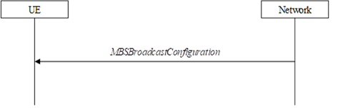
Figure 5.9.2.1-1: MCCH information acquisition
The UE applies the MCCH information
acquisition procedure to acquire the MBS broadcast configuration information
broadcasted by the network. The procedure applies to MBS capable UEs interested
to receive or that are receiving MBS broadcast services that are in RRC_IDLE,
RRC_INACTIVE or RRC_CONNECTED with an active BWP with common search space
configured by searchSpaceMCCH.
A UE shall apply
the MCCH information acquisition procedure upon becoming interested to receive
MBS broadcast services. A UE
interested to receive MBS broadcast services shall apply the MCCH information
acquisition procedure upon entering the cell providing SIB20 (e.g. upon
power on, following UE mobility), upon receiving SIB20 of an SCell via
dedicated signalling and upon receiving a notification that the MCCH
information has changed due to the start of new MBS service(s). A UE that is
receiving data via broadcast MRB shall apply the MCCH information acquisition
procedure upon receiving a notification that the MCCH information has changed
due to MCCH information modification other than the change caused by the start
of new MBS service(s).
NOTE 1: It is up to UE
implementation how to address a possibility of the UE missing an MCCH change
notification.
NOTE 2: It is up to UE implementation to use the
cell/tracking area list in the USD to avoid acquiring the MCCH when the UE is
outside the MBS service area of the MBS broadcast service.
Unless explicitly stated otherwise in the
procedural specification, the MCCH information acquisition procedure overwrites
any stored MCCH information, i.e. delta configuration is not applicable for
MCCH information and the UE discontinues using a field if it is absent in MCCH information.
An MBS capable UE interested to receive or
receiving an MBS broadcast service shall:
1> if the procedure is triggered by an MCCH
information change notification:
2> start acquiring the MBSBroadcastConfiguration
message on MCCH in the concerned cell from the slot in which the change
notification was received;
1> if the UE enters a cell providing SIB20;
or
1> if the UE receives sCellSIB20:
2> acquire the MBSBroadcastConfiguration
message on MCCH in the concerned cell at the next repetition period.
No UE requirements related to the contents
of the MBSBroadcastConfiguration message apply other than those
specified elsewhere e.g. within the corresponding field descriptions.
5.9.3 Broadcast
MRB configuration
The broadcast MRB
configuration procedure is used by the UE to configure PDCP, RLC, MAC and the
physical layer upon starting and/or stopping to receive a broadcast MRB
transmitted on MTCH, or upon modification of a configuration of a broadcast MRB
received by the UE. The procedure applies to MBS capable UEs that are interested
to receive or that are receiving an MBS broadcast service that are in RRC_IDLE,
RRC_INACTIVE or RRC_CONNECTED with an active BWP
with common search space configured by searchSpaceMTCH or
searchSpaceMCCH.
NOTE: How to perform a modification of a
broadcast MRB which is already configured in the UE is left to UE
implementation.
The UE applies the broadcast MRB
establishment procedure to start receiving an MBS session of an MBS broadcast
service it is interested in. The procedure may be initiated e.g. upon start of
the MBS session, upon entering a cell providing an MBS broadcast service the UE
is interested in, upon becoming interested in the ongoing MBS broadcast
service, upon removal of the UE capability limitations inhibiting reception of
the ongoing MBS broadcast service UE is interested in.
The UE applies the broadcast MRB release
procedure to stop receiving a session of an MBS broadcast service. The
procedure may be initiated e.g. upon stop of the MBS session, upon leaving the
cell broadcasting the MBS service the UE is interested in, upon losing interest
in the MBS service, when capability limitations start inhibiting reception of
the concerned service.
5.9.3.3 Broadcast MRB establishment
Upon a broadcast MRB establishment, the UE
shall:
1> establish a PDCP entity and an RLC entity in
accordance with MRB-InfoBroadcast for this broadcast MRB included in the
MBSBroadcastConfiguration message and the configuration specified in 9.1.1.7;
1> configure the MAC layer in accordance with
the mtch-SchedulingInfo (if included);
1> configure the physical layer in accordance
with the mbs-SessionInfoList, searchSpaceMTCH, and pdsch-ConfigMTCH,
applicable for the broadcast MRB;
1> if an SDAP entity with the received mbs-SessionId
does not exist:
2> establish an SDAP entity as specified in TS
37.324 [24] clause 5.1.1;
2> indicate the establishment of the user plane
resources for the mbs-SessionId to upper layers;
1> receive DL-SCH on the cell where the MBSBroadcastConfiguration
message was received for the established broadcast MRB using g-RNTI and mtch-SchedulingInfo
(if included) in this message for this MBS broadcast service.
Upon broadcast MRB release for MBS
broadcast service, the UE shall:
1> release the PDCP entity, RLC entity as well
as the related MAC and physical layer configuration;
1> if the SDAP entity associated with the
corresponding mbs-SessionId has no associated MRB:
2> release the SDAP entity, as specified in TS
37.324 [24] clause 5.1.2;
2> indicate the release of the user plane
resources for the mbs-SessionId to upper layers.
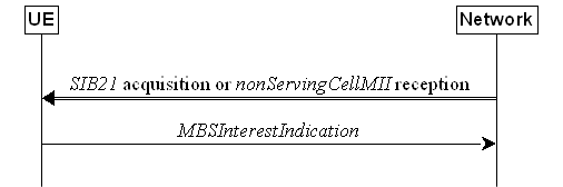
Figure 5.9.4.1-1: MBS Interest Indication
The purpose of this procedure is to inform
the network that the UE in RRC_CONNECTED is receiving or is interested to
receive MBS broadcast service(s) and/or to inform the network about the
priority of MBS broadcast versus unicast and multicast
MRB reception. MBS Interest Indication can only be sent
after AS security activation.
An MBS capable UE in RRC_CONNECTED may
initiate the procedure in several cases including upon successful connection
establishment/resume, upon entering or leaving the broadcast service area, upon
MBS broadcast session start or stop, upon change of interest, upon change of
priority between MBS broadcast reception and unicast/multicast reception, upon
change to a PCell providing SIB21 (i.e. where the SIB1 scheduling
information contains SIB21), upon receiving SIB20 of an SCell via
dedicated signalling, upon handover, and upon RRC connection re-establishment, upon
change to a PCell providing nonServingCellMII in SIB1, upon
starting or stopping reception of MBS broadcast service on a non-serving cell,
upon change of CFR information or subcarrier spacing for MBS broadcast
reception on a non-serving cell. If the UE does not have the CFR information
and subcarrier spacing for MBS broadcast reception on a non-serving cell at the
time it sends the MBS Interest Indication, the UE sends another MBS Interest
Indication after it has acquired this information from the non-serving cell.
Upon initiating the procedure, the UE
shall:
1> if SIB21 is provided by the PCell; or
1> if nonServingCellMII is provided in SIB1
by the PCell:
2> ensure having a valid version of SIB21
for the PCell, if present;
2> if the UE did not transmit MBS Interest
Indication since last entering RRC_CONNECTED state; or
2> if SIB21 is provided and since the
last time the UE transmitted an MBS Interest Indication to a PCell providing SIB21,
the UE connected to a PCell, not providing SIB21; or
2> if nonServingCellMII is provided in SIB1
and since the last time the UE transmitted an MBS Interest Indication to a PCell providing nonServingCellMII
in SIB1, the UE connected to a PCell not providing nonServingCellMII
in SIB1:
3> if the set of MBS broadcast frequencies of
interest, determined in accordance with 5.9.4.3, is not empty:
4> set the contents of MBS Interest Indication
according to 5.9.4.5 and initiate transmission of the MBSInterestIndication
message;
2> else:
3> if the set of MBS broadcast frequencies of
interest, determined in accordance with 5.9.4.3, is different from mbs-FreqList
included in the last transmission of the MBS Interest Indication; or
3> if the set of MBS broadcast frequencies of
interest for MBS broadcast reception on non-serving cell, determined in
accordance with 5.9.4.3, is different from freqInfoMBS included in the
last transmission of the MBS Interest Indication; or
3> if any of the subcarrier spacing and the CFR
information for MBS broadcast reception on non-serving cell has changed since
the last transmission of the MBS Interest Indication; or
3> if the subcarrier spacing and the CFR
information for MBS broadcast reception on non-serving cell have been acquired
from the non-serving cell which were not reported in the previous MBS Interest
Indication; or
3> if the prioritisation of reception of all
indicated MBS broadcast frequencies compared to reception of any of the
established unicast bearers and multicast MRBs has changed since the last
transmission of the MBS Interest Indication:
4> set the contents of MBS Interest Indication
according to 5.9.4.5 and initiate transmission of the MBSInterestIndication
message;
NOTE: The UE may send MBS Interest Indication
even when it is able to receive the MBS services it is interested in, i.e. to
avoid that the network allocates a configuration inhibiting MBS broadcast
reception.
3> else if SIB20 is provided for the
PCell or for the SCell:
4> if since the last time the UE transmitted
the MBS Interest Indication, the UE connected to a PCell not providing SIB20
and the UE was not provided with SIB20 for an SCell; or
4> if the set of MBS broadcast services of
interest determined in accordance with 5.9.4.4 is different from mbs-ServiceList
included in the last transmission of the MBS Interest Indication:
5> set the contents of MBS Interest Indication
according to 5.9.4.5 and initiate the transmission of MBSInterestIndication
message.
The UE shall:
1> consider a frequency to be part of the MBS
frequencies of interest if the following conditions are met:
2> at least one MBS session the UE is receiving
or interested to receive via a broadcast MRB is ongoing or about to start; and
NOTE 1: The UE may determine whether the session
is ongoing or about to start from the start and stop time indicated in the User
Service Description (USD), see TS 38.300 [2] or TS 23.247 [67].
2> for at least one of these MBS sessions, SIB21
acquired from the PCell or a non-serving cell includes mapping between the
concerned frequency and one or more MBS FSAIs indicated in the USD for this
session, or for at least one of these MBS sessions, the concerned frequency is
not included in SIB21 but is indicated in the USD for this session; and
NOTE 2: The UE considers
a frequency to be part of the MBS frequencies of interest even though NG-RAN may (temporarily) not employ a broadcast MRB for
the concerned session, i.e., the UE does not verify if the session is indicated
on MCCH.
2> the supportedBandCombinationList the
UE included in UE-NR-Capability contains at least one band combination
including the concerned MBS frequency.
NOTE 3: When evaluating which frequencies the UE is capable of receiving, the UE does
not take into account whether they are currently configured as serving
frequencies.
The UE shall:
1> consider an MBS service to be part of the
MBS services of interest if the following conditions are met:
2> the UE is receiving or interested to receive
this service via a broadcast MRB; and
2> the session of this service is ongoing or
about to start; and
2> one or more MBS FSAIs in the USD for this
service is included in SIB21 acquired from the PCell for a frequency
belonging to the set of MBS frequencies of interest, determined according to 5.9.4.3
or SIB21 acquired from
the PCell does not provide the frequency mapping for
the concerned service but that frequency is included in
the USD for this service.
NOTE: The UE may determine whether the
session is ongoing or about to start from the start and stop time indicated in
the User Service Description (USD), see TS 38.300 [2] or TS 23.247 [67].
5.9.4.5 Setting of the
contents of MBS Interest Indication
The UE shall set the contents of the MBS
Interest Indication as follows:
1> if the UE has a valid version of SIB21
for the PCell; and
1> if the set of MBS frequencies of interest,
determined in accordance with 5.9.4.3, is not empty:
2> include mbs-FreqList and set it to
include the MBS frequencies of interest sorted by decreasing order of interest,
using the absoluteFrequencySSB for serving frequency, if applicable, and
the ARFCN-ValueNR(s) as included in SIB21 or in USD (for
neighbouring frequencies);
2> include mbs-Priority if the UE
prioritises reception of all indicated MBS frequencies above reception of any
of the unicast bearers and multicast MRBs;
NOTE 1: If the UE prioritises MBS broadcast
reception and unicast/multicast data cannot be supported because of congestion
on the MBS carrier(s), NG-RAN may for example initiate release of unicast
bearers/multicast MRBs.
2> if SIB20 is provided for the PCell or
for the SCell:
3> include mbs-ServiceList and set it to
indicate the set of MBS services of interest sorted by decreasing order of
interest determined in accordance with 5.9.4.4;
NOTE 2: The mbs-ServiceList is not
required to be used by the NG-RAN to determine the frequency on which to enable
MBS broadcast reception for the UE.
1> if nonServingCellMII is provided in SIB1
by the PCell; and
1> if the set of MBS frequencies for MBS
broadcast reception on non-serving cell, determined in accordance with 5.9.4.3,
is not empty:
2> include freqInfoMBS;
2> if the UE has
acquired cfr-InfoMBS and subcarrierSpacing for MBS broadcast
reception on the non-serving cell:
3> include cfr-InfoMBS and subcarrierSpacing.
A UE configured to receive MBS multicast
service(s) in RRC_INACTIVE that the UE has joined applies MBS multicast
procedures described in this clause.
The multicast MCCH information (i.e., the MBSMulticastConfiguration
message) is provided in RRCRelease and on multicast MCCH logical
channel.
When there is temporarily no data for an
active multicast session or when the multicast session is deactivated, the
network notifies the UE to stop monitoring the corresponding G-RNTI via the MBSMulticastConfiguration
message. If the UE is notified to stop monitoring the G-RNTI(s) for all the
joined multicast sessions, it stops monitoring the Multicast MCCH-RNTI for the
cell where it received the notification.
Multicast MCCH carries the MBSMulticastConfiguration
message which indicates the MBS multicast sessions that are provided in the
cell as well as the corresponding scheduling related information for these
sessions. Optionally, the MBSMulticastConfiguration message may also
contain a list of neighbour cells providing the same MBS multicast service(s)
for reception in RRC_INACTIVE as provided in the current cell. The
configuration information required by the UE to receive multicast MCCH is
provided in SIB24.
The multicast MCCH information (if sent on
multicast MCCH logical channel) is transmitted periodically, using a
configurable repetition period and within a configured transmission window. The
multicast MCCH transmissions (and the associated radio resources and MCS) are
indicated via the PDCCH addressed to Multicast MCCH-RNTI. PDCCH monitoring
occasion(s) for the multicast MCCH transmission are determined according to the
common search space indicated by searchSpaceMulticastMCCH. If searchSpaceMulticastMCCH
is set to zero, PDCCH monitoring occasions for the multicast MCCH message
reception in the multicast MCCH transmission window are the same as PDCCH
monitoring occasions for SIB1 where the mapping between PDCCH monitoring
occasions and SSBs is specified in TS 38.213 [13]. If searchSpaceMulticastMCCH
is not set to zero, PDCCH monitoring occasions for the multicast MCCH message
are determined based on search space indicated by searchSpaceMulticastMCCH.
PDCCH monitoring occasions for the multicast MCCH message which are not
overlapping with UL symbols (determined according to tdd-UL-DL-ConfigurationCommon)
are sequentially numbered from one in the multicast MCCH transmission window.
The [x×N+K]th PDCCH monitoring occasion for the multicast MCCH
message in the multicast MCCH transmission window corresponds to the Kth
transmitted SSB, where x = 0, 1, ...X-1, K = 1, 2, …N, N is the number of
actual transmitted SSBs determined according to ssb-PositionsInBurst in SIB1
and X is equal to CEIL(number of PDCCH monitoring occasions in multicast MCCH
transmission window/N). The actual transmitted SSBs are sequentially numbered
from one in ascending order of their SSB indexes. The UE assumes that, in the
multicast MCCH transmission window, PDCCH for a multicast MCCH message is
transmitted in at least one PDCCH monitoring occasion corresponding to each
transmitted SSB and thus the selection of SSB for the reception of multicast
MCCH messages is up to UE implementation.
Change of multicast MCCH information only
occurs at specific radio frames, i.e. the concept of a modification period is
used. Within a modification period, the same multicast MCCH information may be
transmitted a number of times, as defined by its scheduling (which is based on
a repetition period).
When the network changes (some of) the
multicast MCCH information, it notifies the UEs about the change starting from
the beginning of the multicast MCCH modification period via PDCCH which
schedules the multicast MCCH in every repetition in that modification period.
Upon receiving a change notification, a UE
receiving MBS multicast service(s) in RRC_INACTIVE acquires the new multicast
MCCH information starting from the same slot. The UE applies the previously
acquired multicast MCCH information until the UE acquires the new multicast
MCCH information. The notification is transmitted with a 2-bit bitmap, see TS
38.212 [17] clause 7.3.1.5.1. The MSB in the 2-bit bitmap is reserved. The LSB
in the 2-bit bitmap, when set to '1', indicates modification of multicast MCCH
information, e.g. modification of a configuration of an on-going MBS multicast
session, stop of G-RNTI monitoring for the corresponding multicast session or
neighbouring cell information modification.
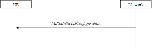
Figure 5.10.2.1-1: Multicast MCCH information
acquisition
The UE applies the multicast MCCH
information acquisition procedure to acquire the MBSMulticastConfiguration
message from the network. The procedure applies to UEs configured to receive
MBS multicast services in RRC_INACTIVE.
If configured to receive MBS multicast
services in RRC_INACTIVE, a UE applies
the multicast MCCH information acquisition procedure for PTM configuration
update and upon selection to a new cell (i.e., different from the cell where
the UE was configured to
receive multicast in RRC_CONNECTED) providing SIB24 or reselection to a
cell providing SIB24 (except in case the UE is
aware that the multicast sessions that the UE has joined are not available for
RRC_INACTIVE in the new cell) and may apply the multicast MCCH information
acquisition procedure upon receiving GroupPaging in the paging message. A UE that is receiving MBS multicast data in RRC_INACTIVE shall
apply the multicast MCCH information acquisition procedure upon receiving a
notification that the multicast MCCH information has changed.
NOTE: It is up to UE implementation how to
address a possibility of the UE missing a multicast MCCH change notification.
Unless explicitly stated otherwise in the
procedural specification, the multicast MCCH information acquisition procedure
overwrites any stored multicast MCCH information as specified in 5.10.1.1, i.e.
delta configuration is not applicable for multicast MCCH information and the UE
discontinues using a field if it is absent in multicast MCCH information.
A UE configured to receive an MBS multicast
service in RRC_INACTIVE shall:
1> if the procedure is triggered by a multicast
MCCH information change notification:
2> start acquiring the MBSMulticastConfiguration
message on multicast MCCH in the concerned cell from the slot in which the
change notification was received;
1> if the UE selects a new cell (i.e.,
different from the cell where the UE was configured to receive multicast in RRC_CONNECTED) providing SIB24 or
reselects a cell providing SIB24; or
1> if the procedure is triggered by the
reception of GroupPaging in the paging message in 5.3.2.3; or
1> if the UE receives RRCRelease
configuring the UE to receive MBS multicast in RRC_INACTIVE which does not
include PTM configuration for at least one multicast session for which the UE
is not indicated to stop monitoring the G-RNTI:
2> acquire the MBSMulticastConfiguration
message on multicast MCCH in the concerned cell at the next repetition period.
No UE requirements related to the contents
of the MBSMulticastConfiguration message apply other than those
specified elsewhere, e.g., within the corresponding field descriptions.
The multicast MRB configuration procedure
is used by the UE in RRC_INACTIVE state to configure PDCP, RLC, MAC entities
and the physical layer upon PTM configuration update and moving to a cell
providing SIB24. The UE may perform multicast MRB modification or
release/establishment when PTM configuration is updated via multicast MCCH or
when it moves to a cell where the PDCP COUNT of the corresponding multicast MRB
is not synchronized within the RNA. The UE may perform multicast MRB
modification when it moves to a cell where the PDCP COUNT of the corresponding
multicast MRB is synchronized within the RNA. The UE resets MAC upon cell selection
or reselection.
NOTE: How to perform modification of a
multicast MRB which is already configured in the UE is left to UE
implementation.
Upon moving to a cell where the PDCP COUNT
of a multicast MRB is not synchronized, an indication
is sent to the lower layer to inform the PDCP COUNT non-synchronization of the
corresponding multicast MRB. Upon transition from RRC_CONNECTED to RRC_INACTIVE
in the same cell, the UE can continue using the multicast MRBs used in RRC_CONNECTED
and in this case, the same LCIDs are used for the same multicast MRBs. Upon
transition from RRC_INACTIVE to RRC_CONNECTED, the UE releases the MRBs
configured in RRCRelease or multicast MCCH and performs delta
configuration based on the stored MRB configuration from RRC_CONNECTED, if not
indicated to perform full configuration.
Upon establishment of a multicast MRB, the
UE shall:
1> establish a PDCP entity and an RLC entity in
accordance with mrb-ListMulticast for this multicast MRB included in the
MBSMulticastConfiguration message;
1> configure the MAC layer in accordance with
the mtch-SchedulingInfo (if included);
1> configure the physical layer in accordance
with the mbs-SessionInfoListMulticast, searchSpaceMulticastMTCH,
and pdsch-ConfigMTCH, applicable for the multicast MRB;
1> if an SDAP entity with the received mbs-SessionId
does not exist:
2> establish an SDAP entity as specified in TS
37.324 [24] clause 5.1.1;
2> indicate the establishment of the user plane
resources for the mbs-SessionId to upper layers;
1> receive DL-SCH for the established multicast
MRB using g-RNTI (if not indicated to stop monitoring this G-RNTI) and mtch-SchedulingInfo
(if included) in this message for this MBS multicast service.
Upon release of a multicast MRB, the UE
shall:
1> release the PDCP entity, RLC entity as well
as the related MAC and physical layer configuration;
1> if the SDAP entity associated with the
corresponding mbs-SessionId has no associated MRB:
2> release the SDAP entity, as specified in TS
37.324 [24] clause 5.1.2;
2> indicate the release of the user plane
resources for the mbs-SessionId to upper layers.
– CounterCheck
The CounterCheck message is used by the network to indicate
the current COUNT MSB values associated to each DRB and to request the UE to compare these to its COUNT MSB values and
to report the comparison results to the network.
Signalling radio bearer: SRB1
RLC-SAP: AM
Logical channel: DCCH
Direction: Network to UE
CounterCheck
message
-- ASN1START
-- TAG-COUNTERCHECK-START
CounterCheck
::= SEQUENCE {
rrc-TransactionIdentifier RRC-TransactionIdentifier,
criticalExtensions CHOICE {
counterCheck CounterCheck-IEs,
criticalExtensionsFuture SEQUENCE {}
}
}
CounterCheck-IEs
::= SEQUENCE {
drb-CountMSB-InfoList DRB-CountMSB-InfoList,
lateNonCriticalExtension OCTET STRING OPTIONAL,
nonCriticalExtension SEQUENCE {} OPTIONAL
}
DRB-CountMSB-InfoList
::= SEQUENCE (SIZE (1..maxDRB)) OF
DRB-CountMSB-Info
DRB-CountMSB-Info
::= SEQUENCE {
drb-Identity DRB-Identity,
countMSB-Uplink INTEGER(0..33554431),
countMSB-Downlink INTEGER(0..33554431)
}
-- TAG-COUNTERCHECK-STOP
-- ASN1STOP
|
CounterCheck-IEs field descriptions
|
|
drb-CountMSB-InfoList
Indicates the MSBs of the COUNT values of the
DRBs.
|
|
DRB-CountMSB-Info field descriptions
|
|
countMSB-Downlink
Indicates the value of 25 MSBs from RX_NEXT – 1
(specified in TS 38.323 [5]) associated to this DRB.
|
|
countMSB-Uplink
Indicates the value of 25 MSBs from TX_NEXT – 1
(specified in TS 38.323 [5]) associated to this DRB.
|
– CounterCheckResponse
The CounterCheckResponse message is used by the UE to respond to a CounterCheck message.
Signalling radio
bearer: SRB1
RLC-SAP: AM
Logical channel:
DCCH
Direction: UE to
Network
CounterCheckResponse message
-- ASN1START
-- TAG-COUNTERCHECKRESPONSE-START
CounterCheckResponse
::= SEQUENCE {
rrc-TransactionIdentifier RRC-TransactionIdentifier,
criticalExtensions CHOICE {
counterCheckResponse CounterCheckResponse-IEs,
criticalExtensionsFuture SEQUENCE {}
}
}
CounterCheckResponse-IEs
::= SEQUENCE {
drb-CountInfoList DRB-CountInfoList,
lateNonCriticalExtension OCTET STRING OPTIONAL,
nonCriticalExtension SEQUENCE {} OPTIONAL
}
DRB-CountInfoList
::= SEQUENCE (SIZE (0..maxDRB)) OF
DRB-CountInfo
DRB-CountInfo
::= SEQUENCE {
drb-Identity DRB-Identity,
count-Uplink INTEGER(0..4294967295),
count-Downlink INTEGER(0..4294967295)
}
--
TAG-COUNTERCHECKRESPONSE-STOP
-- ASN1STOP
|
CounterCheckResponse-IEs field descriptions
|
|
drb-CountInfoList
Indicates the COUNT values of the DRBs.
|
|
DRB-CountInfo field
descriptions
|
|
count-Downlink
Indicates the value of RX_NEXT – 1 (specified
in TS 38.323 [5]) associated to this DRB.
|
|
count-Uplink
Indicates the value of TX_NEXT – 1 (specified
in TS 38.323 [5]) associated to this DRB.
|
The DedicatedSIBRequest message is
used to request SIB(s) required by the UE in RRC_CONNECTED as specified in
clause 5.2.2.3.5.
Signalling radio bearer: SRB1
RLC-SAP: AM
Logical channel: DCCH
Direction: UE to Network
DedicatedSIBRequest message
-- ASN1START
--
TAG-DEDICATEDSIBREQUEST-START
DedicatedSIBRequest-r16
::= SEQUENCE {
criticalExtensions CHOICE {
dedicatedSIBRequest-r16 DedicatedSIBRequest-r16-IEs,
criticalExtensionsFuture SEQUENCE {}
}
}
DedicatedSIBRequest-r16-IEs
::= SEQUENCE {
onDemandSIB-RequestList-r16 SEQUENCE {
requestedSIB-List-r16 SEQUENCE (SIZE (1..maxOnDemandSIB-r16)) OF
SIB-ReqInfo-r16 OPTIONAL,
requestedPosSIB-List-r16 SEQUENCE (SIZE (1..maxOnDemandPosSIB-r16)) OF
PosSIB-ReqInfo-r16 OPTIONAL
} OPTIONAL,
lateNonCriticalExtension OCTET STRING OPTIONAL,
nonCriticalExtension SEQUENCE {} OPTIONAL
}
SIB-ReqInfo-r16
::= ENUMERATED { sib12, sib13, sib14, sib20-v1700, sib21-v1700,
sib23-v1810, spare2, spare1 }
PosSIB-ReqInfo-r16 ::= SEQUENCE {
gnss-id-r16 GNSS-ID-r16 OPTIONAL,
sbas-id-r16 SBAS-ID-r16 OPTIONAL,
posSibType-r16 ENUMERATED { posSibType1-1, posSibType1-2, posSibType1-3,
posSibType1-4, posSibType1-5, posSibType1-6,
posSibType1-7, posSibType1-8, posSibType2-1, posSibType2-2, posSibType2-3,
posSibType2-4,
posSibType2-5, posSibType2-6, posSibType2-7, posSibType2-8, posSibType2-9,
posSibType2-10,
posSibType2-11, posSibType2-12, posSibType2-13, posSibType2-14, posSibType2-15,
posSibType2-16, posSibType2-17, posSibType2-18, posSibType2-19, posSibType2-20,
posSibType2-21, posSibType2-22, posSibType2-23, posSibType3-1, posSibType4-1,
posSibType5-1, posSibType6-1, posSibType6-2, posSibType6-3,...,
posSibType1-9-v1710,
posSibType1-10-v1710, posSibType2-24-v1710, posSibType2-25-v1710,
posSibType6-4-v1710, posSibType6-5-v1710, posSibType6-6-v1710,
posSibType2-17a-v1770,
posSibType2-18a-v1770, posSibType2-20a-v1770, posSibType1-11-v1800, posSibType1-12-v1800,
posSibType2-26-v1800, posSibType2-27-v1800, posSibType6-7-v1800,
posSibType7-1-v1800,
posSibType7-2-v1800, posSibType7-3-v1800, posSibType7-4-v1800 }
}
-- TAG-DEDICATEDSIBREQUEST-STOP
-- ASN1STOP
|
DedicatedSIBRequest field descriptions
|
|
requestedSIB-List
Contains a list of
SIB(s) the UE requests while in RRC_CONNECTED.
|
|
requestedPosSIB-List
Contains a list of posSIB(s) the UE requests
while in RRC_CONNECTED.
|
|
PosSIB-ReqInfo field
descriptions
|
|
gnss-id
The presence of this field indicates that the
request positioning SIB type is for a specific GNSS. Indicates a specific
GNSS (see also TS 37.355 [49])
|
|
sbas-id
The presence of this field indicates that the
request positioning SIB type is for a specific SBAS. Indicates a specific
SBAS (see also TS 37.355 [49]). If the UE includes
this field it shall set gnss-id to sbas.
|
The DLDedicatedMessageSegment message
is used to transfer one segment of the RRCResume
or RRCReconfiguration messages.
Signalling radio bearer: SRB1
RLC-SAP: AM
Logical channel: DCCH
Direction: Network to UE
DLDedicatedMessageSegment message
-- ASN1START
--
TAG-DLDEDICATEDMESSAGESEGMENT-START
DLDedicatedMessageSegment-r16
::= SEQUENCE {
criticalExtensions CHOICE {
dlDedicatedMessageSegment-r16 DLDedicatedMessageSegment-r16-IEs,
criticalExtensionsFuture SEQUENCE {}
}
}
DLDedicatedMessageSegment-r16-IEs
::= SEQUENCE {
segmentNumber-r16 INTEGER(0..4),
rrc-MessageSegmentContainer-r16 OCTET STRING,
rrc-MessageSegmentType-r16 ENUMERATED
{notLastSegment, lastSegment},
lateNonCriticalExtension OCTET STRING OPTIONAL,
nonCriticalExtension SEQUENCE
{} OPTIONAL
}
--
TAG-DLDEDICATEDMESSAGESEGMENT-STOP
-- ASN1STOP
|
DLDedicatedMessageSegment field descriptions
|
|
segmentNumber
Identifies the sequence number of a segment
within the encoded DL DCCH message. The network transmits the segments with continuously increasing segmentNumber
order so that the UE's RRC layer may expect to obtain them from lower layers
in the correct order. Hence, the UE is not required to perform segment
re-ordering on RRC level.
|
|
rrc-MessageSegmentContainer
Includes a segment of the encoded DL DCCH
message. The size of the included segment in this container should be small
enough so the resulting encoded RRC message PDU is less than or equal to the
PDCP SDU size limit.
|
|
rrc-MessageSegmentType
Indicates whether the included DL DCCH message
segment is the last segment of the message or not.
|
The DLInformationTransfer message is
used for the downlink transfer of NAS dedicated information, timing information
for the 5G internal system clock, or IAB-DU specific F1-C related information.
Signalling radio bearer: SRB2 or SRB1 (only if
SRB2 not established yet). If SRB2 is suspended, the network does not send this
message until SRB2 is resumed. If only dedicatedInfoF1c is included,
SRB2 is used.
RLC-SAP: AM
Logical channel: DCCH
Direction: Network to UE
DLInformationTransfer message
-- ASN1START
-- TAG-DLINFORMATIONTRANSFER-START
DLInformationTransfer
::= SEQUENCE {
rrc-TransactionIdentifier RRC-TransactionIdentifier,
criticalExtensions CHOICE {
dlInformationTransfer DLInformationTransfer-IEs,
criticalExtensionsFuture SEQUENCE {}
}
}
DLInformationTransfer-IEs
::= SEQUENCE {
dedicatedNAS-Message DedicatedNAS-Message OPTIONAL, -- Need N
lateNonCriticalExtension OCTET STRING OPTIONAL,
nonCriticalExtension DLInformationTransfer-v1610-IEs OPTIONAL
}
DLInformationTransfer-v1610-IEs
::= SEQUENCE {
referenceTimeInfo-r16 ReferenceTimeInfo-r16 OPTIONAL, -- Need N
nonCriticalExtension DLInformationTransfer-v1700-IEs OPTIONAL
}
DLInformationTransfer-v1700-IEs
::= SEQUENCE {
dedicatedInfoF1c-r17 DedicatedInfoF1c-r17 OPTIONAL, -- Need N
rxTxTimeDiff-gNB-r17 RxTxTimeDiff-r17 OPTIONAL, -- Need N
ta-PDC-r17 ENUMERATED {activate,deactivate} OPTIONAL, -- Need N
sib9Fallback-r17 ENUMERATED {true} OPTIONAL, -- Need N
nonCriticalExtension DLInformationTransfer-v1800-IEs OPTIONAL
}
DLInformationTransfer-v1800-IEs
::= SEQUENCE {
eventID-TSS-r18 INTEGER(0..63) OPTIONAL, -- Cond ClockQualityDetailsLevel
clockQualityDetailsLevel-r18 CHOICE {
clockQualityMetrics-r18 ClockQualityMetrics-r18,
clockQualityAcceptanceStatus-r18 ENUMERATED {acceptable, notAcceptable}
} OPTIONAL, -- Need N
nonCriticalExtension SEQUENCE {} OPTIONAL
}
--
TAG-DLINFORMATIONTRANSFER-STOP
-- ASN1STOP
|
DLInformationTransfer field descriptions
|
|
clockQualityDetailsLevel
This field indicates the clock quality
reporting control information as defined in TS 23.501 [32].
|
|
eventID-TSS
This field indicates the status of the 5G
access stratum time distribution parameter Clock Quality Reporting Control
Information as defined in TS 23.501 [32].
|
|
rxTxTimeDiff-gNB
Indicates the Rx-Tx time difference measurement
at the gNB (see clause 5.2.3, TS 38.215 [9]). Upon receiving this field, the
UE calculates the propagation delay based on the RTT-based
PDC mechanism method as described in TS 38.300 [2].
The network does not configure this field, if the UE is configured with ta-PDC
with value activate.
|
|
sib9Fallback
Indicates that the UE fallbacks to receive referenceTimeInfo in SIB9.
|
|
ta-PDC
Indicates whether the UE-side TA-based
propagation delay compensation (PDC) is activated or de-activated. The
network does not configure this field with activate, if the field rxTxTimeDiff-gNB
is configured.
|
|
Conditional Presence
|
Explanation
|
|
ClockQualityDetailsLevel
|
Field eventID-TSS is mandatory present if
clockQualityDetailsLevel is present. Otherwise, the field is optionally present, Need M.
|
The DLInformationTransferMRDC
message is used for the downlink transfer of RRC messages during fast MCG link
recovery.
Signalling radio bearer: SRB3
RLC-SAP: AM
Logical channel: DCCH
Direction: Network to UE
DLInformationTransferMRDC message
-- ASN1START
--
TAG-DLINFORMATIONTRANSFERMRDC-START
DLInformationTransferMRDC-r16
::= SEQUENCE {
criticalExtensions CHOICE {
c1 CHOICE {
dlInformationTransferMRDC-r16 DLInformationTransferMRDC-r16-IEs,
spare3 NULL,
spare2 NULL, spare1 NULL
},
criticalExtensionsFuture SEQUENCE {}
}
}
DLInformationTransferMRDC-r16-IEs::=
SEQUENCE {
dl-DCCH-MessageNR-r16 OCTET STRING OPTIONAL, --
Need N
dl-DCCH-MessageEUTRA-r16 OCTET STRING OPTIONAL, --
Need N
lateNonCriticalExtension OCTET STRING OPTIONAL,
nonCriticalExtension SEQUENCE
{} OPTIONAL
}
--
TAG-DLINFORMATIONTRANSFERMRDC-STOP
-- ASN1STOP
|
DLInformationTransferMRDC field descriptions
|
|
dl-DCCH-MessageNR
Includes the DL-DCCH-Message. In this
version of the specification, the field is only used to transfer the NR RRCReconfiguration,
RRCRelease, and MobilityFromNRCommand messages.
|
|
dl-DCCH-MessageEUTRA
Includes the DL-DCCH-Message. In this
version of the specification, the field is only used to transfer the E-UTRA RRCConnectionReconfiguration,
RRCConnectionRelease, and MobilityFromEUTRACommand messages as
specified in TS 36.331 [10].
|
The FailureInformation message is
used to inform the network about a failure detected by the UE.
Signalling radio
bearer: SRB1 or SRB3
RLC-SAP: AM
Logical channel: DCCH
Direction: UE to network
FailureInformation message
-- ASN1START
-- TAG-FAILUREINFORMATION-START
FailureInformation ::=
SEQUENCE {
criticalExtensions CHOICE {
failureInformation FailureInformation-IEs,
criticalExtensionsFuture SEQUENCE {}
}
}
FailureInformation-IEs ::=
SEQUENCE {
failureInfoRLC-Bearer FailureInfoRLC-Bearer OPTIONAL,
lateNonCriticalExtension OCTET STRING OPTIONAL,
nonCriticalExtension FailureInformation-v1610-IEs OPTIONAL
}
FailureInfoRLC-Bearer ::=
SEQUENCE {
cellGroupId CellGroupId,
logicalChannelIdentity LogicalChannelIdentity,
failureType ENUMERATED {rlc-failure, spare3, spare2, spare1}
}
FailureInformation-v1610-IEs
::= SEQUENCE {
failureInfoDAPS-r16 FailureInfoDAPS-r16 OPTIONAL,
nonCriticalExtension SEQUENCE {} OPTIONAL
}
FailureInfoDAPS-r16
::= SEQUENCE {
failureType-r16 ENUMERATED {daps-failure, spare3, spare2, spare1}
}
-- TAG-FAILUREINFORMATION-STOP
-- ASN1STOP
– IABOtherInformation
The IABOtherInformation
message is used by IAB-MT
to request the network to allocate IP addresses for the
collocated IAB-DU or inform the network about IP
addresses allocated to the collocated IAB-DU.
Signalling radio bearer: SRB1 or SRB3
RLC-SAP: AM
Logical channel: DCCH
Direction: IAB-MT to Network
IABOtherInformation
message
-- ASN1START
--
TAG-IABOTHERINFORMATION-START
IABOtherInformation-r16
::= SEQUENCE {
dummy RRC-TransactionIdentifier,
criticalExtensions CHOICE {
iabOtherInformation-r16 IABOtherInformation-r16-IEs,
criticalExtensionsFuture SEQUENCE {}
}
}
IABOtherInformation-r16-IEs
::= SEQUENCE {
ip-InfoType-r16 CHOICE {
iab-IP-Request-r16 SEQUENCE {
iab-IPv4-AddressNumReq-r16 IAB-IP-AddressNumReq-r16
OPTIONAL,
iab-IPv6-AddressReq-r16 CHOICE {
iab-IPv6-AddressNumReq-r16 IAB-IP-AddressNumReq-r16,
iab-IPv6-AddressPrefixReq-r16 IAB-IP-AddressPrefixReq-r16,
...
}
OPTIONAL
},
iab-IP-Report-r16 SEQUENCE {
iab-IPv4-AddressReport-r16 IAB-IP-AddressAndTraffic-r16
OPTIONAL,
iab-IPv6-Report-r16 CHOICE {
iab-IPv6-AddressReport-r16 IAB-IP-AddressAndTraffic-r16,
iab-IPv6-PrefixReport-r16 IAB-IP-PrefixAndTraffic-r16,
...
}
OPTIONAL
},
...
},
lateNonCriticalExtension OCTET STRING OPTIONAL,
nonCriticalExtension SEQUENCE {} OPTIONAL
}
IAB-IP-AddressNumReq-r16
::= SEQUENCE {
all-Traffic-NumReq-r16 INTEGER (1..8) OPTIONAL,
f1-C-Traffic-NumReq-r16 INTEGER (1..8) OPTIONAL,
f1-U-Traffic-NumReq-r16 INTEGER (1..8) OPTIONAL,
non-F1-Traffic-NumReq-r16 INTEGER (1..8) OPTIONAL,
...
}
IAB-IP-AddressPrefixReq-r16
::= SEQUENCE {
all-Traffic-PrefixReq-r16 ENUMERATED {true} OPTIONAL,
f1-C-Traffic-PrefixReq-r16 ENUMERATED {true} OPTIONAL,
f1-U-Traffic-PrefixReq-r16 ENUMERATED {true} OPTIONAL,
non-F1-Traffic-PrefixReq-r16 ENUMERATED {true} OPTIONAL,
...
}
IAB-IP-AddressAndTraffic-r16
::= SEQUENCE {
all-Traffic-IAB-IP-Address-r16 SEQUENCE (SIZE(1..8)) OF IAB-IP-Address-r16
OPTIONAL,
f1-C-Traffic-IP-Address-r16 SEQUENCE (SIZE(1..8)) OF IAB-IP-Address-r16
OPTIONAL,
f1-U-Traffic-IP-Address-r16 SEQUENCE (SIZE(1..8)) OF IAB-IP-Address-r16
OPTIONAL,
non-F1-Traffic-IP-Address-r16 SEQUENCE (SIZE(1..8)) OF IAB-IP-Address-r16
OPTIONAL
}
IAB-IP-PrefixAndTraffic-r16
::= SEQUENCE {
all-Traffic-IAB-IP-Address-r16 IAB-IP-Address-r16
OPTIONAL,
f1-C-Traffic-IP-Address-r16 IAB-IP-Address-r16
OPTIONAL,
f1-U-Traffic-IP-Address-r16 IAB-IP-Address-r16
OPTIONAL,
non-F1-Traffic-IP-Address-r16 IAB-IP-Address-r16
OPTIONAL
}
-- TAG-IABOTHERINFORMATION-STOP
-- ASN1STOP
|
IABOtherInformation-IEs field descriptions
|
|
dummy
This field is not used in the specification and
network ignores the received value.
|
|
iab-IPv4-AddressNumReq
This field is used to request the numbers of
IPv4 address per specific usage. The specific usages include F1-C traffic,
F1-U traffic, non-F1 traffic and all traffic.
|
|
iab-IPv4-AddressReport
This field is used to report the IPv4 address
per specific usage assigned by OAM for IAB-DU. The specific usages include
F1-C traffic, F1-U traffic, non-F1 traffic and all traffic.
|
|
iab-IPv6-AddressNumReq
This field is used to request the numbers of
IPv6 address per specific usage. The specific usages include F1-C traffic,
F1-U traffic, non-F1 traffic and all traffic.
|
|
iab-IPv6-AddressPrefixReq
This field is used to request the prefix of
IPv6 address per specific usage. The specific usages include F1-C traffic,
F1-U traffic, non-F1 traffic and all traffic.
|
|
iab-IPv6-AddressReport
This field is used to report the IPv6 address
per specific usage assigned by OAM for IAB-DU. The specific usages include
F1-C traffic, F1-U traffic, non-F1 traffic and all traffic.
|
|
iab-IPv6-PrefixReport
This field is used to report the prefix of IPv6
address per specific usage assigned by OAM for IAB-DU. The specific usages
include F1-C traffic, F1-U traffic, non-F1 traffic and all traffic.
|
|
IAB-IP-AddressNumReq-IEs field descriptions
|
|
all-Traffic-NumReq
This field is used to request the numbers of IP
address for all traffic.
|
|
f1-C-Traffic-NumReq
This field is used to request the numbers of IP
address for F1-C traffic.
|
|
f1-U-Traffic-NumReq
This field is used to request the numbers of IP
address for F1-U traffic.
|
|
non-F1-Traffic-NumReq
This field is used to request the numbers of IP
address for non-F1 traffic.
|
|
IAB-IP-AddressPrefixReq-IEs field
descriptions
|
|
all-Traffic-PrefixReq
This field is used to request the IPv6 address
prefix for all traffic. The length of allocated IPv6 prefix is fixed to 64.
|
|
f1-C-Traffic-PrefixReq
This field is used to request the IPv6 address
prefix for F1-C traffic. The length of allocated IPv6 prefix is fixed to 64.
|
|
f1-U-Traffic-PrefixReq
This field is used to request the IPv6 address
prefix for F1-U traffic. The length of allocated IPv6 prefix is fixed to 64.
|
|
non-F1-Traffic-PrefixReq
This field is used to request the IPv6 address
prefix for non-F1 traffic. The length of allocated IPv6 prefix is fixed to
64.
|
|
IAB-IP-AddressAndTraffic-IEs field
descriptions
|
|
all-Traffic-IAB-IP-Address
This field is used to report to IAB-donor-CU
the IP address(es) or IPv6 address prefix for all traffic.
|
|
f1-C-Traffic-IP-Address
This field is used to report to IAB-donor-CU
the IP address(es) or IPv6 address prefix for F1-C traffic.
|
|
f1-U-Traffic-IP-Address
This field is used to report to IAB-donor-CU
the IP address(es) or IPv6 address prefix for F1-U traffic.
|
|
non-F1-Traffic-IP-Address
This field is used to report to IAB-donor-CU
the IP address(es) or IPv6 address prefix for non-F1 traffic.
|
The IndirectPathFailureInformation
message is used to provide information regarding indirect path failure detected
by the MP remote UE.
Signalling radio bearer: SRB1
RLC-SAP: AM
Logical channel: DCCH
Direction: UE to Network
IndirectPathFailureInformation message
-- ASN1START
--
TAG-INDIRECTPATHFAILUREINFORMATION-START
IndirectPathFailureInformation-r18
::= SEQUENCE {
criticalExtensions CHOICE {
indirectPathFailureInformation-r18
IndirectPathFailureInformation-r18-IEs,
criticalExtensionsFuture SEQUENCE {}
}
}
IndirectPathFailureInformation-r18-IEs
::= SEQUENCE {
failureReportIndirectPath-r18
FailureReportIndirectPath-r18
OPTIONAL,
lateNonCriticalExtension OCTET STRING OPTIONAL,
nonCriticalExtension SEQUENCE {}
OPTIONAL
}
FailureReportIndirectPath-r18
::= SEQUENCE {
failureTypeIndirectPath-r18 ENUMERATED
{t421-Expiry,sl-Failure,n3c-Failure, relayUE-Uu-RLF,
relayUE-Uu-RRC-Failure,
indirectPathAddChangeFailure, sl-PC5-Release, spare1} OPTIONAL,
sl-MeasResultServingRelay-r18
OCTET STRING OPTIONAL,
-- Contains PC5 SL-MeasResultRelay-r17
sl-MeasResultsCandRelay-r18
OCTET STRING OPTIONAL,
n3c-RelayUE-InfoList-r18 SEQUENCE (SIZE
(0..8)) OF N3C-RelayUE-Info-r18 OPTIONAL,
...
}
--
TAG-INDIRECTPATHFAILUREINFORMATION-STOP
-- ASN1STOP
|
IndirectPathFailureInformation field descriptions
|
|
failureTypeIndirectPath
The field indicates the failure type of the
indirect path failure.
|
|
n3c-RelayUE-InfoList
Information of available N3C relay UE(s).
|
|
sl-MeasResultsCandRelay
Measurement result(s) of candiate L2 U2N relay
UE(s).
|
|
sl-MeasResultServingRelay
Measurement result of serving L2 U2N relay UE.
|
The LocationMeasurementIndication message
is used to indicate that the UE is going to either start or stop location
related measurement which requires measurement gaps.
Signalling radio bearer: SRB1
RLC-SAP: AM
Logical channel: DCCH
Direction: UE to Network
LocationMeasurementIndication message
-- ASN1START
-- TAG-LOCATIONMEASUREMENTINDICATION-START
LocationMeasurementIndication
::= SEQUENCE {
criticalExtensions CHOICE {
locationMeasurementIndication LocationMeasurementIndication-IEs,
criticalExtensionsFuture SEQUENCE {}
}
}
LocationMeasurementIndication-IEs
::= SEQUENCE {
measurementIndication SetupRelease
{LocationMeasurementInfo},
lateNonCriticalExtension OCTET STRING
OPTIONAL,
nonCriticalExtension SEQUENCE{}
OPTIONAL
}
--
TAG-LOCATIONMEASUREMENTINDICATION-STOP
-- ASN1STOP
The LoggedMeasurementConfiguration message
is used to perform logging of measurement results while in RRC_IDLE or RRC_INACTIVE. It is used to transfer the
logged measurement configuration for network performance optimisation.
Signalling radio bearer: SRB1
RLC-SAP: AM
Logical channel: DCCH
Direction: Network to UE
LoggedMeasurementConfiguration message
-- ASN1START
--
TAG-LOGGEDMEASUREMENTCONFIGURATION-START
LoggedMeasurementConfiguration-r16
::= SEQUENCE {
criticalExtensions CHOICE {
loggedMeasurementConfiguration-r16 LoggedMeasurementConfiguration-r16-IEs,
criticalExtensionsFuture SEQUENCE {}
}
}
LoggedMeasurementConfiguration-r16-IEs
::= SEQUENCE {
traceReference-r16 TraceReference-r16,
traceRecordingSessionRef-r16 OCTET STRING (SIZE (2)),
tce-Id-r16 OCTET STRING (SIZE (1)),
absoluteTimeInfo-r16 AbsoluteTimeInfo-r16,
areaConfiguration-r16
AreaConfiguration-r16 OPTIONAL, --Need R
plmn-IdentityList-r16
PLMN-IdentityList2-r16 OPTIONAL, --Need R
bt-NameList-r16 SetupRelease
{BT-NameList-r16} OPTIONAL, --Need
M
wlan-NameList-r16 SetupRelease
{WLAN-NameList-r16} OPTIONAL, --Need
M
sensor-NameList-r16 SetupRelease
{Sensor-NameList-r16} OPTIONAL, --Need
M
loggingDuration-r16 LoggingDuration-r16,
reportType CHOICE {
periodical LoggedPeriodicalReportConfig-r16,
eventTriggered LoggedEventTriggerConfig-r16,
...
},
lateNonCriticalExtension OCTET STRING OPTIONAL,
nonCriticalExtension LoggedMeasurementConfiguration-v1700-IEs
OPTIONAL
}
LoggedMeasurementConfiguration-v1700-IEs
::= SEQUENCE {
sigLoggedMeasType-r17 ENUMERATED
{true} OPTIONAL, --
Need R
earlyMeasIndication-r17 ENUMERATED
{true} OPTIONAL, --
Need R
areaConfiguration-r17
AreaConfiguration-r17 OPTIONAL, --Need R
nonCriticalExtension
LoggedMeasurementConfiguration-v1800-IEs OPTIONAL
}
LoggedMeasurementConfiguration-v1800-IEs
::= SEQUENCE {
areaConfiguration-v1800
AreaConfiguration-v1800 OPTIONAL, --Need R
nonCriticalExtension SEQUENCE
{} OPTIONAL
}
LoggedPeriodicalReportConfig-r16
::= SEQUENCE {
loggingInterval-r16 LoggingInterval-r16,
...
}
LoggedEventTriggerConfig-r16
::= SEQUENCE {
eventType-r16 EventType-r16,
loggingInterval-r16 LoggingInterval-r16,
...
}
EventType-r16 ::= CHOICE {
outOfCoverage NULL,
eventL1
SEQUENCE {
l1-Threshold
MeasTriggerQuantity,
hysteresis
Hysteresis,
timeToTrigger
TimeToTrigger
},
...
}
--
TAG-LOGGEDMEASUREMENTCONFIGURATION-STOP
-- ASN1STOP
|
LoggedMeasurementConfiguration field descriptions
|
|
absoluteTimeInfo
Indicates the absolute
time in the current cell.
|
|
areaConfiguration
Used to restrict the
area in which the UE performs measurement logging to cells broadcasting any
of the included cell identities, the included tracking area codes/
frequencies, the included PNI-NPN identities or the SNPN identities. If areaConfiguration-r17 is present, the UE shall ignore areaConfiguration-r16.
The areaConfiguration-v1800 is a non-critical extension of areaConfiguration-r17. See NOTE 1.
|
|
earlyMeasIndication
If included, the field indicates the UE is
allowed to log measurements on early measurement related frequencies in
logged measurements.
|
|
eventType
The value outOfCoverage indicates the UE to
perform logging of measurements when the UE enters any cell selection state,
and the value eventL1 indicates the UE to perform logging of measurements
when the triggering condition (similar as event A2 as specified in 5.5.4.3)
as configured in the event is met for the camping cell in camped normally
state.
|
|
plmn-IdentityList
Indicates a set of PLMNs defining when the UE
performs measurement logging as well as the associated status indication and
information retrieval i.e. the UE performs these actions when the RPLMN is
part of this set of PLMNs. The
network does not include this field when the
UE is configured with MDT configuration in SNPN access mode.
|
|
sigLoggedMeasType
If included, the field indicates a signalling
based logged measurement configuration (See TS 37.320 [61]).
|
|
tce-Id
Parameter Trace
Collection Entity Id: See TS 32.422 [52].
|
|
traceRecordingSessionRef
Parameter Trace Recording Session Reference:
See TS 32.422 [52].
|
|
reportType
Parameter configures the type of MDT
configuration, specifically Periodic MDT configuration or Event Triggerd MDT
configuration.
|
NOTE 1: The UE should
perform measurement logging based on the following area configuration
limitations:
- If the areaConfiguration-r16/areaConfiguration-r17
is present, and the cag-ConfigList is absent, the UE should perform
logging in both PN and PNI-NPN based on areaConfiguration-r16/areaConfiguration-r17,
if any;
- If the areaConfiguration-r17 and the cag-ConfigList
are present simultaneously, the UE should perform logging in PN within the areaConfig-r16/areaConfig-r17
and perform logging in PNI-NPN within cag-ConfigList;
- If the snpn-ConfigList is present, the
UE should perform logging only in SNPN based on snpn-ConfigList. The
snpn-ConfigList should not be configured together with PN or PNI-NPN area
configurations.
The MBSBroadcastConfiguration
message contains the control information applicable for MBS broadcast services
transmitted via broadcast MRB.
Signalling radio bearer: N/A
RLC-SAP: UM
Logical channel: MCCH
Direction: Network to UE
MBSBroadcastConfiguration message
-- ASN1START
-- TAG-MBSBROADCASTCONFIGURATION-START
MBSBroadcastConfiguration-r17
::= SEQUENCE {
criticalExtensions CHOICE {
mbsBroadcastConfiguration-r17 MBSBroadcastConfiguration-r17-IEs,
criticalExtensionsFuture SEQUENCE {}
}
}
MBSBroadcastConfiguration-r17-IEs
::= SEQUENCE {
mbs-SessionInfoList-r17 MBS-SessionInfoList-r17
OPTIONAL, -- Need R
mbs-NeighbourCellList-r17
MBS-NeighbourCellList-r17 OPTIONAL, -- Need S
drx-ConfigPTM-List-r17 SEQUENCE (SIZE
(1..maxNrofDRX-ConfigPTM-r17)) OF DRX-ConfigPTM-r17 OPTIONAL, -- Need R
pdsch-ConfigMTCH-r17
PDSCH-ConfigBroadcast-r17 OPTIONAL, -- Need S
mtch-SSB-MappingWindowList-r17
MTCH-SSB-MappingWindowList-r17 OPTIONAL, -- Need R
lateNonCriticalExtension OCTET STRING OPTIONAL,
nonCriticalExtension SEQUENCE
{} OPTIONAL
}
--
TAG-MBSBROADCASTCONFIGURATION-STOP
-- ASN1STOP
|
MBSBroadcastConfiguration field descriptions
|
|
pdsch-ConfigMTCH
Provides parameters for acquiring the PDSCH for
MTCH. When this field is absent, the UE shall use parameters in pdsch-ConfigMCCH to acquire the PDSCH for
MTCH.
|
|
mbs-SessionInfoList
Provides the configuration of each MBS session
provided by MBS broadcast in the current cell.
|
|
mbs-NeighbourCellList
List of neighbour cells providing one or more MBS
broadcast services via broadcast MRB that are provided by the current cell.
This field is used by the UE together with mtch-NeighbourCell field
signalled for each MBS session in the corresponding MBS-SessionInfo.
When an empty mbs-NeighbourCellList list is signalled, the UE shall assume that MBS broadcast services
signalled in mbs-SessionInfoList in the MBSBroadcastConfiguration message are not provided
in any neighbour cell. When a non-empty mbs-NeighbourCellList
is signalled, the current serving cell does not provide information about MBS
broadcast services of a neighbour cell that is not included in mbs-NeighbourCellList,
i.e., the UE cannot determine the presence or absence of an MBS service of a
neighbour cell that is absent. When the field mbs-NeighbourCellList is absent, the current serving cell does not provide information
about MBS broadcast services in the neighbouring cells, i.e. the UE cannot
determine the presence or absence of an MBS service in neighbouring cells
based on the absence of this field.
|
The MBSInterestIndication message is
used to inform network that the UE is receiving/ interested to receive or no
longer receiving/ interested to receive MBS broadcast service(s) via a
broadcast MRB.
Signalling radio bearer: SRB1
RLC-SAP: AM
Logical channel: DCCH
Direction: UE to Network
MBSInterestIndication message
-- ASN1START
--
TAG-MBSINTERESTINDICATION-START
MBSInterestIndication-r17 ::= SEQUENCE {
criticalExtensions CHOICE {
mbsInterestIndication-r17 MBSInterestIndication-r17-IEs,
criticalExtensionsFuture SEQUENCE {}
}
}
MBSInterestIndication-r17-IEs
::= SEQUENCE {
mbs-FreqList-r17 CarrierFreqListMBS-r17 OPTIONAL,
mbs-Priority-r17 ENUMERATED {true} OPTIONAL,
mbs-ServiceList-r17 MBS-ServiceList-r17 OPTIONAL,
lateNonCriticalExtension OCTET STRING OPTIONAL,
nonCriticalExtension MBSInterestIndication-v1800 OPTIONAL
}
MBSInterestIndication-v1800
::= SEQUENCE {
mbs-NonServingInfoList-r18 MBS-NonServingInfoList-r18 OPTIONAL,
nonCriticalExtension SEQUENCE {}
OPTIONAL
}
--
TAG-MBSINTERESTINDICATION-STOP
-- ASN1STOP
|
MBSInterestIndication field descriptions
|
|
mbs-FreqList
List of MBS frequencies on which the UE is
receiving or interested to receive MBS broadcast service via a broadcast MRB.
|
|
mbs-NonServingInfoList
Indicates information for MBS broadcast
reception on the non-serving cell.
|
|
mbs-Priority
Indicates whether the UE prioritises MBS
broadcast reception above unicast and MBS multicast reception. The field is
present (i.e. value true), if the UE prioritises reception of
broadcast services, on frequencies indicated in mbs-FreqList, above a
reception of any of the unicast bearers and multicast MRBs. Otherwise the
field is absent.
|
|
mbs-ServiceList
List of MBS broadcast services which the UE is
receiving or interested to receive.
|
The MBSMulticastConfiguration
message contains the control information applicable for MBS multicast services
transmitted via multicast MRBs for RRC_INACTIVE UEs.
Signalling radio bearer: N/A
RLC-SAP: UM
Logical channel: multicast MCCH
Direction: Network to UE
MBSMulticastConfiguration message
-- ASN1START
--
TAG-MBSMULTICASTCONFIGURATION-START
MBSMulticastConfiguration-r18
::= SEQUENCE {
criticalExtensions CHOICE {
mbsMulticastConfiguration-r18 MBSMulticastConfiguration-r18-IEs,
criticalExtensionsFuture SEQUENCE {}
}
}
MBSMulticastConfiguration-r18-IEs
::= SEQUENCE {
mbs-SessionInfoListMulticast-r18
MBS-SessionInfoListMulticast-r18 OPTIONAL, -- Need R
mbs-NeighbourCellList-r18
MBS-NeighbourCellList-r17 OPTIONAL, -- Need S
drx-ConfigPTM-List-r18 SEQUENCE (SIZE
(1..maxNrofDRX-ConfigPTM-r17)) OF DRX-ConfigPTM-r17 OPTIONAL, -- Need R
pdsch-ConfigMTCH-r18
PDSCH-ConfigBroadcast-r17 OPTIONAL, -- Need S
mtch-SSB-MappingWindowList-r18
MTCH-SSB-MappingWindowList-r17 OPTIONAL, -- Need R
thresholdMBS-List-r18 SEQUENCE (SIZE
(1..maxNrofThresholdMBS-r18)) OF ThresholdMBS-r18 OPTIONAL, -- Need R
lateNonCriticalExtension OCTET STRING OPTIONAL,
nonCriticalExtension SEQUENCE
{} OPTIONAL
}
ThresholdMBS-r18
::= SEQUENCE {
rsrp-r18 RSRP-Range
OPTIONAL, -- Need R
rsrq-r18 RSRQ-Range
OPTIONAL -- Need R
}
--
TAG-MBSMULTICASTCONFIGURATION-STOP
-- ASN1STOP
|
MBSMulticastConfiguration field descriptions
|
|
mbs-NeighbourCellList
List of neighbour cells providing one or more
MBS multicast services for RRC_INACTIVE that are provided by the current
cell. This field is used by the UE together with mtch-NeighbourCell
field signalled for each MBS session in the corresponding MBS-SessionInfo.
When an empty mbs-NeighbourCellList list is signalled, the UE shall assume
that MBS multicast services signalled in mbs-SessionInfoListMulticast in the MBSMulticastConfiguration message are not provided
in any neighbour cell. When a non-empty mbs-NeighbourCellList is
signalled, the current serving cell does not provide information about MBS
multicast services of a neighbour cell that is not included in mbs-NeighbourCellList,
i.e., the UE cannot determine the presence or absence of an MBS multicast
service of a neighbour cell that is absent. When the field mbs-NeighbourCellList is absent, the current serving cell does not provide information
about MBS multicast services in the neighbouring cells, i.e. the UE cannot
determine the presence or absence of an MBS multicast service in
neighbouring cells based on the absence of this field.
|
|
mbs-SessionInfoListMulticast
Provides the configuration of MBS multicast session(s)
in the current cell.
|
|
pdsch-ConfigMTCH
Provides parameters for acquiring the PDSCH for
multicast MTCH. When this field is absent, the UE shall use parameters in pdsch-ConfigMCCH in SIB24
to acquire the PDSCH for multicast MTCH.
|
|
thresholdMBS-List
List of reception quality thresholds for RRC connection
resume for a UE receiving multicast in RRC_INACTIVE.
|
The MCGFailureInformation message is
used to provide information regarding NR MCG failures detected by the UE.
Signalling radio bearer: SRB1
RLC-SAP: AM
Logical channel: DCCH
Direction: UE to Network
MCGFailureInformation message
-- ASN1START
--
TAG-MCGFAILUREINFORMATION-START
MCGFailureInformation-r16 ::= SEQUENCE {
criticalExtensions CHOICE {
mcgFailureInformation-r16 MCGFailureInformation-r16-IEs,
criticalExtensionsFuture SEQUENCE {}
}
}
MCGFailureInformation-r16-IEs
::= SEQUENCE {
failureReportMCG-r16 FailureReportMCG-r16 OPTIONAL,
lateNonCriticalExtension OCTET STRING OPTIONAL,
nonCriticalExtension SEQUENCE {}
OPTIONAL
}
FailureReportMCG-r16 ::= SEQUENCE {
failureType-r16
ENUMERATED {t310-Expiry, randomAccessProblem, rlc-MaxNumRetx,
t312-Expiry-r16, lbt-Failure-r16,
beamFailureRecoveryFailure-r16,
bh-RLF-r16, spare1}
OPTIONAL,
measResultFreqList-r16 MeasResultList2NR
OPTIONAL,
measResultFreqListEUTRA-r16 MeasResultList2EUTRA
OPTIONAL,
measResultSCG-r16
OCTET STRING (CONTAINING
MeasResultSCG-Failure) OPTIONAL,
measResultSCG-EUTRA-r16 OCTET STRING
OPTIONAL,
measResultFreqListUTRA-FDD-r16
MeasResultList2UTRA
OPTIONAL,
...
}
MeasResultList2UTRA ::= SEQUENCE (SIZE (1..maxFreq)) OF
MeasResult2UTRA-FDD-r16
MeasResult2UTRA-FDD-r16
::= SEQUENCE {
carrierFreq-r16 ARFCN-ValueUTRA-FDD-r16,
measResultNeighCellList-r16 MeasResultListUTRA-FDD-r16
}
MeasResultList2EUTRA ::= SEQUENCE (SIZE
(1..maxFreq)) OF MeasResult2EUTRA-r16
--
TAG-MCGFAILUREINFORMATION-STOP
-- ASN1STOP
|
MCGFailureInformation field descriptions
|
|
measResultFreqList
The field contains available results of
measurements on NR frequencies the UE is configured to measure by the measConfig
associated with the MCG.
|
|
measResultFreqListEUTRA
The field contains available results of
measurements on E-UTRA frequencies the UE is configured to measure by measConfig
associated with the MCG.
|
|
measResultFreqListUTRA-FDD
The field contains available results of
measurements on UTRA FDD frequencies the UE is configured to measure by
measConfig associated with the MCG.
|
|
measResultSCG
The field contains the MeasResultSCG-Failure
IE which includes available measurement results on NR frequencies the UE is
configured to measure by the measConfig associated with the SCG.
|
|
measResultSCG-EUTRA
The field contains the EUTRA MeasResultSCG-FailureMRDC
IE which includes available results of measurements on E-UTRA frequencies
the UE is configured to measure by the E-UTRA RRCConnectionReconfiguration
message as specified in TS 36.331 [10].
|
The MeasurementReport message is
used for the indication of measurement results.
Signalling radio bearer: SRB1, SRB3
RLC-SAP: AM
Logical channel: DCCH
Direction: UE to Network
MeasurementReport message
-- ASN1START
-- TAG-MEASUREMENTREPORT-START
MeasurementReport
::= SEQUENCE {
criticalExtensions CHOICE {
measurementReport MeasurementReport-IEs,
criticalExtensionsFuture SEQUENCE {}
}
}
MeasurementReport-IEs
::= SEQUENCE {
measResults MeasResults,
lateNonCriticalExtension OCTET STRING
OPTIONAL,
nonCriticalExtension SEQUENCE{}
OPTIONAL
}
-- TAG-MEASUREMENTREPORT-STOP
-- ASN1STOP
The MeasurementReportAppLayer
message is used for sending application layer measurement report.
Signalling radio bearer: SRB4, SRB5
RLC-SAP: AM
Logical channel: DCCH
Direction: UE to Network
MeasurementReportAppLayer message
--
ASN1START
--
TAG-MEASUREMENTREPORTAPPLAYER-START
MeasurementReportAppLayer-r17
::= SEQUENCE {
criticalExtensions CHOICE {
measurementReportAppLayer-r17
MeasurementReportAppLayer-r17-IEs,
criticalExtensionsFuture SEQUENCE {}
}
}
MeasurementReportAppLayer-r17-IEs
::= SEQUENCE {
measurementReportAppLayerList-r17 MeasurementReportAppLayerList-r17,
lateNonCriticalExtension OCTET STRING OPTIONAL,
nonCriticalExtension MeasurementReportAppLayer-v1800-IEs
OPTIONAL
}
MeasurementReportAppLayer-v1800-IEs
::= SEQUENCE {
measurementReportAppLayerList-v1800 MeasurementReportAppLayerList-v1800
OPTIONAL,
nonCriticalExtension SEQUENCE{}
OPTIONAL
}
MeasurementReportAppLayerList-r17
::= SEQUENCE (SIZE (1..maxNrofAppLayerMeas-r17)) OF
MeasReportAppLayer-r17
MeasurementReportAppLayerList-v1800
::= SEQUENCE (SIZE (1..maxNrofAppLayerMeas-r17)) OF
MeasReportAppLayer-v1800
MeasReportAppLayer-r17 ::= SEQUENCE {
measConfigAppLayerId-r17
MeasConfigAppLayerId-r17,
measReportAppLayerContainer-r17
OCTET STRING
OPTIONAL,
appLayerSessionStatus-r17 ENUMERATED {start,
stop} OPTIONAL,
ran-VisibleMeasurements-r17
RAN-VisibleMeasurements-r17 OPTIONAL
}
MeasReportAppLayer-v1800
::= SEQUENCE {
appLayerIdleInactiveConfig-r18
AppLayerIdleInactiveConfig-r18 OPTIONAL,
measReportAppLayerContainerList-r18 SEQUENCE (SIZE
(1..maxNrofAppLayerReports-r18))
OF OCTET STRING OPTIONAL,
...
}
RAN-VisibleMeasurements-r17
::= SEQUENCE {
appLayerBufferLevelList-r17 SEQUENCE (SIZE
(1..8)) OF AppLayerBufferLevel-r17 OPTIONAL,
playoutDelayForMediaStartup-r17
INTEGER
(0..30000) OPTIONAL,
pdu-SessionIdList-r17 SEQUENCE (SIZE
(1..maxNrofPDU-Sessions-r17)) OF PDU-SessionID OPTIONAL,
...,
[[
pdu-SessionIdListExt-v1800
SEQUENCE (SIZE (1..maxNrofPDU-Sessions-r17)) OF
QFI-List-r18 OPTIONAL
]]
}
AppLayerBufferLevel-r17 ::= INTEGER (0..30000)
QFI-List-r18 ::= SEQUENCE (SIZE (1..maxNrofQFIs)) OF QFI
--
TAG-MEASUREMENTREPORTAPPLAYER-STOP
-- ASN1STOP
|
MeasurementReportAppLayer field descriptions
|
|
measurementReportAppLayerList
The field contains a list of application layer
measurement reports. If measurementReportAppLayerList-v1800 is
present, it contains the same number of entries, listed in the same order as
in measurementReportAppLayerList-r17.
|
|
MeasReportAppLayer field descriptions
|
|
appLayerSessionStatus
Indicates that an application layer measurement
session in the application layer starts or ends. For application layer
measurements applicable to RRC_IDLE or RRC_INACTIVE, the UE transmits appLayerSessionStatus
upon transfer to RRC_CONNECTED if transmissionOfSessionStartStop is
set to true for the application layer measurement configuration.
|
|
measReportAppLayerContainer
The field contains the application layer
measurement report container, see Annex L (normative) in TS 26.247 [68],
clause 16.5 in TS 26.114 [69] and clause 9.4 in TS 26.118 [70].
|
|
measReportAppLayerContainerList
The field contains a list of application layer
measurement report containers for each measConfigAppLayerId, see Annex
L (normative) in TS 26.247 [68], clause 16.5 in TS 26.114 [69] and clause 9.4
in TS 26.118 [70].
|
|
ran-VisibleMeasurements
The field contains the RAN visible application
layer measurement report.
|
|
RAN-VisibleMeasurements field descriptions
|
|
appLayerBufferLevelList
The field indicates a list of application layer
buffer levels, and each AppLayerBufferLevel indicates the application
layer buffer level in ms. Value 0 corresponds to 0 ms, value 1 corresponds to
10 ms, value 2 corresponds to 20 ms and so on. If the buffer level is larger
than the maximum value of 30000 (5 minutes), the UE reports 30000.
|
|
playoutDelayForMediaStartup
Indicates the application layer playout delay
for media start-up in ms. Value 0 corresponds to 0 ms, value 1 corresponds to
1 ms, value 2 corresponds to 2 ms and so on. If the playout delay for media
start-up is larger than the maximum value of 30000 ms, the UE reports 30000.
|
|
pdu-SessionIdList
List of PDU session identities and QoS flow
identities per PDU session associated with the application data flows subject
to the RAN visible application layer measurements. If pdu-SessionIdListExt-v1800
is present, it contains the same number of entries, listed in the same
order as in pdu-SessionIdList-r17.
|
The MIB includes the system
information transmitted on BCH.
Signalling radio
bearer: N/A
RLC-SAP: TM
Logical channel:
BCCH
Direction: Network
to UE
MIB
-- ASN1START
-- TAG-MIB-START
MIB
::= SEQUENCE {
systemFrameNumber BIT STRING (SIZE (6)),
subCarrierSpacingCommon ENUMERATED {scs15or60, scs30or120},
ssb-SubcarrierOffset INTEGER (0..15),
dmrs-TypeA-Position ENUMERATED {pos2, pos3},
pdcch-ConfigSIB1 PDCCH-ConfigSIB1,
cellBarred ENUMERATED {barred, notBarred},
intraFreqReselection ENUMERATED {allowed, notAllowed},
spare BIT STRING (SIZE (1))
}
-- TAG-MIB-STOP
-- ASN1STOP
|
MIB field
descriptions
|
|
cellBarred
Value barred means that the cell is
barred, as defined in TS 38.304 [20]. This field is ignored by IAB-MT and NCR-MT. This field is ignored
for connectivity to NTN or ATG.
|
|
dmrs-TypeA-Position
Position of (first) DM-RS for downlink (see TS
38.211 [16], clause 7.4.1.1.2) and uplink (see TS 38.211 [16], clause
6.4.1.1.3).
|
|
intraFreqReselection
Controls cell selection/reselection to
intra-frequency cells when the highest ranked cell is barred, or treated as
barred by the UE, as specified in TS 38.304 [20]. This field is ignored by IAB-MT, NCR-MT
and (e)RedCap UE.
|
|
pdcch-ConfigSIB1
Determines a common ControlResourceSet
(CORESET), a common search space and necessary PDCCH parameters. If the field ssb-SubcarrierOffset indicates that SIB1
is absent, the field pdcch-ConfigSIB1 indicates the frequency
positions where the UE may find SS/PBCH block with SIB1 or the
frequency range where the network does not provide SS/PBCH block with SIB1
(see TS 38.213 [13], clause 13).
|
|
ssb-SubcarrierOffset
Corresponds to kSSB (see TS 38.213
[13]), which is the frequency domain offset between SSB and the overall
resource block grid in number of subcarriers. (See TS 38.211 [16], clause
7.4.3.1). For operation with
shared spectrum channel access in FR1 (see 37.213 [48]), this field
corresponds to  , and kSSB
is obtained from (see TS 38.211
[16], clause 7.4.3.1); the LSB of this field is used also for deriving the
QCL relation between SS/PBCH blocks as specified in TS 38.213 [13], clause
4.1. , and kSSB
is obtained from (see TS 38.211
[16], clause 7.4.3.1); the LSB of this field is used also for deriving the
QCL relation between SS/PBCH blocks as specified in TS 38.213 [13], clause
4.1.
The value range of this field may be extended
by an additional most significant bit encoded within PBCH as specified in TS
38.213 [13].
This field may indicate that this cell does not provide SIB1 and that
there is hence no CORESET#0 configured in MIB (see TS 38.213 [13], clause 13).
In this case, the field pdcch-ConfigSIB1 may indicate the frequency
positions where the UE may (not) find a SS/PBCH with a control resource set
and search space for SIB1 (see TS 38.213 [13], clause 13).
|
|
subCarrierSpacingCommon
Subcarrier spacing for SIB1, Msg.2/4 and MsgB for initial
access, paging and broadcast
SI-messages. If the UE acquires this MIB on an FR1 carrier frequency, the value scs15or60
corresponds to 15 kHz and the value scs30or120 corresponds to 30 kHz.
If the UE acquires this MIB on an FR2 carrier frequency, the value scs15or60
corresponds to 60 kHz and the value scs30or120 corresponds to 120 kHz.
For operation with shared spectrum channel access in
FR1 (see 37.213 [48]) and for operation in FR2-2, the
subcarrier spacing for SIB1, Msg.2/4 and MsgB for initial access, paging and broadcast SI-messages is same
as that for the corresponding SSB. For operation with
shared spectrum channel access, this field instead is
used for deriving the QCL relation between SS/PBCH
blocks as specified in TS 38.213 [13], clause 4.1.
|
|
systemFrameNumber
The 6 most significant bits (MSB) of the 10-bit
System Frame Number (SFN). The 4 LSB of the SFN are conveyed in the PBCH
transport block as part of channel coding (i.e. outside the MIB encoding), as
defined in clause 7.1 in TS 38.212 [17].
|
The MobilityFromNRCommand message is
used to command handover from NR to E-UTRA/EPC, E-UTRA/5GC
or UTRA-FDD.
Signalling radio bearer: SRB1
RLC-SAP: AM
Logical channel: DCCH
Direction: Network to UE
MobilityFromNRCommand message
-- ASN1START
--
TAG-MOBILITYFROMNRCOMMAND-START
MobilityFromNRCommand
::= SEQUENCE {
rrc-TransactionIdentifier RRC-TransactionIdentifier,
criticalExtensions CHOICE {
mobilityFromNRCommand MobilityFromNRCommand-IEs,
criticalExtensionsFuture SEQUENCE {}
}
}
MobilityFromNRCommand-IEs
::= SEQUENCE {
targetRAT-Type ENUMERATED { eutra, utra-fdd-v1610, spare2, spare1, ...},
targetRAT-MessageContainer OCTET STRING,
nas-SecurityParamFromNR OCTET STRING OPTIONAL, -- Cond
HO-ToEPCUTRAN
lateNonCriticalExtension OCTET STRING OPTIONAL,
nonCriticalExtension
MobilityFromNRCommand-v1610-IEs OPTIONAL
}
MobilityFromNRCommand-v1610-IEs
::= SEQUENCE {
voiceFallbackIndication-r16 ENUMERATED
{true} OPTIONAL, -- Need N
nonCriticalExtension SEQUENCE
{} OPTIONAL
}
--
TAG-MOBILITYFROMNRCOMMAND-STOP
-- ASN1STOP
|
MobilityFromNRCommand-IEs field descriptions
|
|
nas-SecurityParamFromNR
If targetRAT-Type is eutra, this
field is used to deliver the key synchronisation and Key freshness for the NR
to LTE/EPC handovers and a part of the downlink NAS COUNT as specified in TS
33.501 [11] and the content of the parameter is defined in TS 24.501 [23]. If
targetRAT-Type is utra-fdd, this field is used to deliver the
key synchronisation and Key freshness for the NR to FDD UTRAN handover and a
part of the downlink NAS COUNT as specified in TS 33.501 [11] and the content
of the parameter is defined in TS 24.501 [23].
|
|
targetRAT-MessageContainer
The field contains a message specified in
another standard, as indicated by the targetRAT-Type, and carries information about the target cell identifier(s) and
radio parameters relevant for the target radio access technology. A complete
message is included, as specified in the other standard. See NOTE 1
|
|
targetRAT-Type
Indicates the target RAT type.
|
|
voiceFallbackIndication
Indicates the handover is triggered by EPS
fallback for IMS voice as specified in TS 23.502 [43].
|
NOTE 1: The correspondence between the value of
the targetRAT-Type, the standard to apply, and the message contained
within the targetRAT-MessageContainer is shown in the table below:
|
targetRAT-Type
|
Standard to apply
|
targetRAT-MessageContainer
|
|
eutra
|
TS 36.331 [10] (clause 5.4.2)
|
DL-DCCH-Message
including the RRCConnectionReconfiguration
|
|
utra-fdd
|
TS 25.331 [45] (clause 10.2.16a)
|
Handover TO UTRAN command
|
|
Conditional Presence
|
Explanation
|
|
HO-ToEPCUTRAN
|
This field is mandatory present in case of
inter system handover to "EPC" or "FDD UTRAN". Otherwise
it is absent.
|
The Paging message is used for the
notification of one or more UEs.
Signalling radio bearer: N/A
RLC-SAP: TM
Logical channel: PCCH
Direction: Network to UE
Paging message
-- ASN1START
-- TAG-PAGING-START
Paging
::= SEQUENCE {
pagingRecordList
PagingRecordList OPTIONAL, -- Need N
lateNonCriticalExtension OCTET STRING
OPTIONAL,
nonCriticalExtension Paging-v1700-IEs
OPTIONAL
}
Paging-v1700-IEs
::= SEQUENCE {
pagingRecordList-v1700
PagingRecordList-v1700 OPTIONAL, -- Need N
pagingGroupList-r17
PagingGroupList-r17 OPTIONAL, -- Need N
nonCriticalExtension Paging-v1800-IEs
OPTIONAL
}
Paging-v1800-IEs
::= SEQUENCE {
pagingRecordList-v1800
PagingRecordList-v1800 OPTIONAL, -- Need N
pagingGroupList-v1800
PagingGroupList-v1800 OPTIONAL, -- Need N
nonCriticalExtension SEQUENCE
{} OPTIONAL
}
PagingRecordList
::= SEQUENCE (SIZE(1..maxNrofPageRec)) OF
PagingRecord
PagingRecordList-v1700
::= SEQUENCE (SIZE(1..maxNrofPageRec)) OF
PagingRecord-v1700
PagingGroupList-r17
::= SEQUENCE (SIZE(1..maxNrofPageGroup-r17)) OF
TMGI-r17
PagingRecordList-v1800
::= SEQUENCE (SIZE(1..maxNrofPageRec)) OF
PagingRecord-v1800
PagingGroupList-v1800
::= SEQUENCE (SIZE(1..maxNrofPageGroup-r17)) OF
GroupPaging-r18
PagingRecord
::= SEQUENCE {
ue-Identity PagingUE-Identity,
accessType ENUMERATED {non3GPP} OPTIONAL, -- Need N
...
}
PagingRecord-v1700
::= SEQUENCE {
pagingCause-r17 ENUMERATED {voice} OPTIONAL -- Need N
}
PagingRecord-v1800
::= SEQUENCE {
mt-SDT ENUMERATED {true} OPTIONAL -- Need N
}
PagingUE-Identity
::= CHOICE {
ng-5G-S-TMSI NG-5G-S-TMSI,
fullI-RNTI I-RNTI-Value,
...
}
GroupPaging-r18
::= SEQUENCE {
inactiveReceptionAllowed-r18 ENUMERATED {true} OPTIONAL -- Need N
}
-- TAG-PAGING-STOP
-- ASN1STOP
|
PagingRecord field
descriptions
|
|
accessType
Indicates whether the Paging message is originated due to
the PDU sessions from the non-3GPP access.
|
|
inactiveReceptionAllowed
Indicates whether the UE with a valid PTM
configuration for a TMGI in the PagingGroupList stays in RRC_INACTIVE to receive the corresponding MBS multicast
session.
|
|
mt-SDT
Mobile Terminated SDT indication. The network includes mt-SDT indication in paging message
only if the UE's I-RNTI is included in the paging message.
|
|
pagingRecordList
If the network includes pagingRecordList-v1700,
it includes the same number of entries, and listed in the same order, as in
pagingRecordList (i.e. without suffix). If the network includes pagingRecordList-v1800, it includes
the same number of entries, and listed in the same order, as in pagingRecordList (i.e. without
suffix). The first element in pagingRecordList-v1700 corresponds to the first UE identity in pagingRecordList (i.e. without
suffix). The second element in pagingRecordList-v1700 corresponds to the second UE identity in pagingRecordList (i.e. without
suffix), and so on. The first element in pagingRecordList-v1800 corresponds to the first UE identity in pagingRecordList (i.e. without
suffix). The second element in pagingRecordList-v1800 corresponds to the second UE identity in pagingRecordList (i.e. without
suffix), and so on.
|
|
pagingCause
Indicates whether the Paging message is
originated due to IMS voice. If this field is present, it implies that the
corresponding paging entry is for IMS voice. If upper
layers indicate the support of paging cause and if
this field is not present but pagingRecordList-v1700 is present, it implies
that the corresponding paging entry is for a service other than IMS voice.
Otherwise, paging cause is undetermined.
|
|
pagingGroupList
If the network includes pagingGroupList-v1800,
it includes the same number of elements, and listed in the same order, as in pagingGroupList-r17.
The first element corresponds to the first TMGI in pagingGroupList-r17.
The second element
corresponds to the second TMGI in pagingGroupList-r17, and so on.
|
The RRCReestablishment message is
used to re-establish SRB1.
Signalling radio bearer: SRB1
RLC-SAP: AM
Logical channel: DCCH
Direction: Network to UE
RRCReestablishment message
-- ASN1START
-- TAG-RRCREESTABLISHMENT-START
RRCReestablishment
::= SEQUENCE {
rrc-TransactionIdentifier RRC-TransactionIdentifier,
criticalExtensions CHOICE {
rrcReestablishment RRCReestablishment-IEs,
criticalExtensionsFuture SEQUENCE {}
}
}
RRCReestablishment-IEs
::= SEQUENCE {
nextHopChainingCount NextHopChainingCount,
lateNonCriticalExtension OCTET STRING OPTIONAL,
nonCriticalExtension RRCReestablishment-v1700-IEs OPTIONAL
}
RRCReestablishment-v1700-IEs
::= SEQUENCE {
sl-L2RemoteUE-Config-r17
SetupRelease {SL-L2RemoteUE-Config-r17} OPTIONAL, -- Cond L2RemoteUE
nonCriticalExtension SEQUENCE {} OPTIONAL
}
-- TAG-RRCREESTABLISHMENT-STOP
-- ASN1STOP
|
RRCReestablishment-IEs field descriptions
|
|
sl-L2RemoteUE-Config
Contains dedicated configurations used for L2
U2N relay related operation. The network configures only the SRAP
configuration for local UE ID.
|
|
Conditional Presence
|
Explanation
|
|
L2RemoteUE
|
The field is mandatory present for L2 U2N Remote UE; otherwise it is absent.
|
The RRCReestablishmentComplete
message is used to confirm the successful completion of an RRC connection
re-establishment.
Signalling radio bearer: SRB1
RLC-SAP: AM
Logical channel: DCCH
Direction: UE to Network
RRCReestablishmentComplete message
-- ASN1START
--
TAG-RRCREESTABLISHMENTCOMPLETE-START
RRCReestablishmentComplete
::= SEQUENCE {
rrc-TransactionIdentifier RRC-TransactionIdentifier,
criticalExtensions CHOICE {
rrcReestablishmentComplete RRCReestablishmentComplete-IEs,
criticalExtensionsFuture SEQUENCE {}
}
}
RRCReestablishmentComplete-IEs
::= SEQUENCE {
lateNonCriticalExtension OCTET STRING OPTIONAL,
nonCriticalExtension
RRCReestablishmentComplete-v1610-IEs OPTIONAL
}
RRCReestablishmentComplete-v1610-IEs
::= SEQUENCE {
ue-MeasurementsAvailable-r16 UE-MeasurementsAvailable-r16 OPTIONAL,
nonCriticalExtension RRCReestablishmentComplete-v1800-IEs
OPTIONAL
}
RRCReestablishmentComplete-v1800-IEs
::= SEQUENCE {
flightPathInfoAvailable-r18 ENUMERATED
{true} OPTIONAL,
measConfigReportAppLayerAvailable-r18 ENUMERATED
{true} OPTIONAL,
musim-CapRestrictionInd-r18 ENUMERATED
{true} OPTIONAL,
nonCriticalExtension SEQUENCE
{} OPTIONAL
}
--
TAG-RRCREESTABLISHMENTCOMPLETE-STOP
-- ASN1STOP
|
RRCReestablishmentComplete-IEs field descriptions
|
|
measConfigReportAppLayerAvailable
Indication that the UE has at least one
application layer measurement configuration with appLayerIdleInactiveConfig
configured.
|
|
musim-CapRestrictionInd
This field indicates the UE temporary
capability restriction due to MUSIM operation.
|
The RRCReestablishmentRequest
message is used to request the reestablishment of an RRC connection.
Signalling radio bearer: SRB0
RLC-SAP: TM
Logical channel: CCCH
Direction: UE to Network
RRCReestablishmentRequest message
-- ASN1START
--
TAG-RRCREESTABLISHMENTREQUEST-START
RRCReestablishmentRequest
::= SEQUENCE {
rrcReestablishmentRequest RRCReestablishmentRequest-IEs
}
RRCReestablishmentRequest-IEs
::= SEQUENCE {
ue-Identity ReestabUE-Identity,
reestablishmentCause ReestablishmentCause,
spare BIT STRING (SIZE (1))
}
ReestabUE-Identity
::= SEQUENCE {
c-RNTI RNTI-Value,
physCellId PhysCellId,
shortMAC-I ShortMAC-I
}
ReestablishmentCause
::= ENUMERATED {reconfigurationFailure, handoverFailure,
otherFailure, spare1}
--
TAG-RRCREESTABLISHMENTREQUEST-STOP
-- ASN1STOP
|
ReestabUE-Identity field descriptions
|
|
physCellId
The Physical Cell Identity of the PCell the UE
was connected to prior to the failure.
|
|
RRCReestablishmentRequest-IEs field descriptions
|
|
reestablishmentCause
Indicates the failure cause that triggered the
re-establishment procedure. gNB is not expected to reject a RRCReestablishmentRequest due to
unknown cause value being used by the UE.
|
|
ue-Identity
UE identity included to retrieve UE context and
to facilitate contention resolution by lower layers.
|
The RRCReconfiguration message is
the command to modify an RRC connection. It may convey information for measurement
configuration, mobility control, radio resource configuration (including RBs,
MAC main configuration and physical channel configuration) and AS security
configuration.
Signalling radio bearer: SRB1 or SRB3
RLC-SAP: AM
Logical channel: DCCH
Direction: Network to UE
RRCReconfiguration message
-- ASN1START
-- TAG-RRCRECONFIGURATION-START
RRCReconfiguration
::= SEQUENCE {
rrc-TransactionIdentifier RRC-TransactionIdentifier,
criticalExtensions CHOICE {
rrcReconfiguration RRCReconfiguration-IEs,
criticalExtensionsFuture SEQUENCE {}
}
}
RRCReconfiguration-IEs
::= SEQUENCE {
radioBearerConfig
RadioBearerConfig OPTIONAL, -- Need M
secondaryCellGroup OCTET STRING (CONTAINING CellGroupConfig) OPTIONAL, -- Cond SCG
measConfig
MeasConfig OPTIONAL, -- Need M
lateNonCriticalExtension OCTET STRING OPTIONAL,
nonCriticalExtension
RRCReconfiguration-v1530-IEs OPTIONAL
}
RRCReconfiguration-v1530-IEs
::= SEQUENCE {
masterCellGroup OCTET STRING (CONTAINING CellGroupConfig) OPTIONAL, -- Need M
fullConfig ENUMERATED
{true} OPTIONAL, -- Cond
FullConfig
dedicatedNAS-MessageList SEQUENCE (SIZE(1..maxDRB)) OF
DedicatedNAS-Message OPTIONAL, -- Cond nonHO
masterKeyUpdate
MasterKeyUpdate OPTIONAL, -- Cond
MasterKeyChange
dedicatedSIB1-Delivery OCTET STRING (CONTAINING SIB1) OPTIONAL, -- Need N
dedicatedSystemInformationDelivery OCTET STRING (CONTAINING SystemInformation) OPTIONAL, -- Need N
otherConfig
OtherConfig OPTIONAL, -- Need M
nonCriticalExtension
RRCReconfiguration-v1540-IEs OPTIONAL
}
RRCReconfiguration-v1540-IEs
::= SEQUENCE {
otherConfig-v1540
OtherConfig-v1540 OPTIONAL, -- Need M
nonCriticalExtension
RRCReconfiguration-v1560-IEs OPTIONAL
}
RRCReconfiguration-v1560-IEs
::= SEQUENCE {
mrdc-SecondaryCellGroupConfig SetupRelease {
MRDC-SecondaryCellGroupConfig } OPTIONAL, -- Need M
radioBearerConfig2 OCTET STRING (CONTAINING RadioBearerConfig) OPTIONAL, -- Need M
sk-Counter
SK-Counter OPTIONAL, -- Need N
nonCriticalExtension
RRCReconfiguration-v1610-IEs OPTIONAL
}
RRCReconfiguration-v1610-IEs
::= SEQUENCE {
otherConfig-v1610
OtherConfig-v1610 OPTIONAL, -- Need M
bap-Config-r16 SetupRelease { BAP-Config-r16
} OPTIONAL, -- Need M
iab-IP-AddressConfigurationList-r16
IAB-IP-AddressConfigurationList-r16 OPTIONAL, -- Need M
conditionalReconfiguration-r16
ConditionalReconfiguration-r16 OPTIONAL, -- Need M
daps-SourceRelease-r16 ENUMERATED{true}
OPTIONAL, -- Need N
t316-r16 SetupRelease
{T316-r16} OPTIONAL, -- Need M
needForGapsConfigNR-r16 SetupRelease
{NeedForGapsConfigNR-r16} OPTIONAL, -- Need M
onDemandSIB-Request-r16 SetupRelease { OnDemandSIB-Request-r16
} OPTIONAL, --
Need M
dedicatedPosSysInfoDelivery-r16 OCTET STRING (CONTAINING PosSystemInformation-r16-IEs) OPTIONAL, -- Need N
sl-ConfigDedicatedNR-r16 SetupRelease
{SL-ConfigDedicatedNR-r16} OPTIONAL, -- Need M
sl-ConfigDedicatedEUTRA-Info-r16 SetupRelease
{SL-ConfigDedicatedEUTRA-Info-r16} OPTIONAL, -- Need M
targetCellSMTC-SCG-r16
SSB-MTC OPTIONAL, -- Need S
nonCriticalExtension RRCReconfiguration-v1700-IEs
OPTIONAL
}
RRCReconfiguration-v1700-IEs
::= SEQUENCE {
otherConfig-v1700
OtherConfig-v1700 OPTIONAL, -- Need M
sl-L2RelayUE-Config-r17
SetupRelease { SL-L2RelayUE-Config-r17 } OPTIONAL, -- Need M
sl-L2RemoteUE-Config-r17
SetupRelease { SL-L2RemoteUE-Config-r17 } OPTIONAL, -- Need M
dedicatedPagingDelivery-r17 OCTET STRING (CONTAINING Paging) OPTIONAL, -- Cond
PagingRelay
needForGapNCSG-ConfigNR-r17
SetupRelease {NeedForGapNCSG-ConfigNR-r17} OPTIONAL, -- Need M
needForGapNCSG-ConfigEUTRA-r17
SetupRelease {NeedForGapNCSG-ConfigEUTRA-r17} OPTIONAL, -- Need M
musim-GapConfig-r17 SetupRelease
{MUSIM-GapConfig-r17} OPTIONAL, -- Need M
ul-GapFR2-Config-r17 SetupRelease { UL-GapFR2-Config-r17
} OPTIONAL, --
Need M
scg-State-r17 ENUMERATED {
deactivated } OPTIONAL, -- Need S
appLayerMeasConfig-r17
AppLayerMeasConfig-r17 OPTIONAL, -- Need M
ue-TxTEG-RequestUL-TDOA-Config-r17 SetupRelease
{UE-TxTEG-RequestUL-TDOA-Config-r17} OPTIONAL, -- Need M
nonCriticalExtension RRCReconfiguration-v1800-IEs
OPTIONAL
}
RRCReconfiguration-v1800-IEs
::= SEQUENCE {
needForInterruptionConfigNR-r18 ENUMERATED {
disabled, enabled } OPTIONAL, -- Need M
aerial-Config-r18
SetupRelease { Aerial-Config-r18 } OPTIONAL, -- Need M
sl-IndirectPathAddChange-r18 SetupRelease
{ SL-IndirectPathAddChange-r18 }
OPTIONAL, --
Need M
n3c-IndirectPathAddChange-r18 SetupRelease
{ N3C-IndirectPathAddChange-r18 }
OPTIONAL, --
Need M
n3c-IndirectPathConfigRelay-r18 SetupRelease
{ N3C-IndirectPathConfigRelay-r18 }
OPTIONAL, --
Need M
otherConfig-v1800
OtherConfig-v1800 OPTIONAL, -- Need M
srs-PosResourceSetAggBW-CombinationList-r18
SetupRelease { SRS-PosResourceSetAggBW-CombinationList-r18 } OPTIONAL, -- Need M
ltm-Config-r18 SetupRelease
{LTM-Config-r18} OPTIONAL, -- Need M
nonCriticalExtension RRCReconfiguration-v1830-IEs
OPTIONAL
}
RRCReconfiguration-v1830-IEs
::= SEQUENCE {
otherConfig-v1830
OtherConfig-v1830 OPTIONAL, -- Need M
nonCriticalExtension SEQUENCE
{} OPTIONAL
}
MRDC-SecondaryCellGroupConfig
::= SEQUENCE {
mrdc-ReleaseAndAdd ENUMERATED
{true} OPTIONAL, -- Need N
mrdc-SecondaryCellGroup CHOICE {
nr-SCG OCTET STRING (CONTAINING RRCReconfiguration),
eutra-SCG OCTET STRING
}
}
BAP-Config-r16
::= SEQUENCE {
bap-Address-r16 BIT STRING (SIZE (10)) OPTIONAL, -- Need M
defaultUL-BAP-RoutingID-r16
BAP-RoutingID-r16 OPTIONAL, -- Need M
defaultUL-BH-RLC-Channel-r16
BH-RLC-ChannelID-r16 OPTIONAL, -- Need M
flowControlFeedbackType-r16 ENUMERATED
{perBH-RLC-Channel, perRoutingID, both} OPTIONAL, -- Need R
...
}
MasterKeyUpdate
::= SEQUENCE {
keySetChangeIndicator BOOLEAN,
nextHopChainingCount NextHopChainingCount,
nas-Container OCTET STRING
OPTIONAL, -- Cond
securityNASC
...
}
OnDemandSIB-Request-r16
::= SEQUENCE {
onDemandSIB-RequestProhibitTimer-r16 ENUMERATED
{s0, s0dot5, s1, s2, s5, s10, s20, s30}
}
T316-r16 ::= ENUMERATED {ms50, ms100, ms200, ms300, ms400, ms500, ms600, ms1000,
ms1500, ms2000}
IAB-IP-AddressConfigurationList-r16
::= SEQUENCE {
iab-IP-AddressToAddModList-r16 SEQUENCE (SIZE(1..maxIAB-IP-Address-r16)) OF
IAB-IP-AddressConfiguration-r16 OPTIONAL, --
Need N
iab-IP-AddressToReleaseList-r16 SEQUENCE (SIZE(1..maxIAB-IP-Address-r16)) OF
IAB-IP-AddressIndex-r16 OPTIONAL, --
Need N
...
}
IAB-IP-AddressConfiguration-r16
::= SEQUENCE {
iab-IP-AddressIndex-r16 IAB-IP-AddressIndex-r16,
iab-IP-Address-r16
IAB-IP-Address-r16 OPTIONAL, -- Need M
iab-IP-Usage-r16
IAB-IP-Usage-r16 OPTIONAL, -- Need M
iab-donor-DU-BAP-Address-r16 BIT STRING (SIZE(10))
OPTIONAL, -- Need M
...
}
SL-ConfigDedicatedEUTRA-Info-r16
::= SEQUENCE {
sl-ConfigDedicatedEUTRA-r16 OCTET STRING OPTIONAL, -- Need M
sl-TimeOffsetEUTRA-List-r16 SEQUENCE (SIZE
(8)) OF SL-TimeOffsetEUTRA-r16 OPTIONAL -- Need M
}
SL-TimeOffsetEUTRA-r16
::= ENUMERATED {ms0, ms0dot25, ms0dot5, ms0dot625, ms0dot75,
ms1, ms1dot25, ms1dot5, ms1dot75,
ms2, ms2dot5, ms3, ms4, ms5, ms6, ms8, ms10, ms20}
UE-TxTEG-RequestUL-TDOA-Config-r17
::= CHOICE {
oneShot-r17 NULL,
periodicReporting-r17 ENUMERATED {
ms160, ms320, ms1280, ms2560, ms61440, ms81920, ms368640, ms737280 }
}
SRS-PosResourceSetAggBW-CombinationList-r18
::= SEQUENCE (SIZE(1.. maxNrOfLinkedSRS-PosResSetComb-r18)) OF
SRS-PosResourceSetLinkedForAggBW-List-r18
SRS-PosResourceSetLinkedForAggBW-List-r18
::= SEQUENCE (SIZE(2..maxNrOfLinkedSRS-PosResourceSet-r18)) OF
SRS-PosResourceSetLinkedForAggBW-r18
-- TAG-RRCRECONFIGURATION-STOP
-- ASN1STOP
|
RRCReconfiguration-IEs field descriptions
|
|
appLayerMeasConfig
This field is used to configure application layer measurements. This
field is absent when the UE is configured to operate with shared spectrum
channel access or if sl-L2RemoteUE-Config-r17 is configured or not released.
|
|
bap-Config
This field is used to configure the BAP entity
for IAB nodes.
|
|
bap-Address
Indicates the BAP address of an IAB-node. The
BAP address of an IAB-node cannot be changed once configured for the cell
group to the BAP entity.
|
|
conditionalReconfiguration
Configuration of candidate target SpCell(s) and
execution condition(s) for conditional handover,
conditional PSCell addition or conditional PSCell
change. The field is absent if any
DAPS bearer is configured, if
the sl-L2RemoteUE-Config or sl-L2RelayUE-Config is configured,
or if the RRCReconfiguration message is contained within condRRCReconfig. When the masterCellGroup
and/or secondaryCellGroup includes ReconfigurationWithSync, if
this field is present, it only includes configurations/fields specific to
subsequent CPAC. The RRCReconfiguration
message contained in DLInformationTransferMRDC cannot contain the
field conditionalReconfiguration for conditional PSCell change or for conditional
PSCell addition. The network does not include this
field in an RRCReconfiguration message
contained within a LTM-Config IE.
|
|
daps-SourceRelease
Indicates to UE that the source cell part of
DAPS operation is to be stopped and the source cell part of DAPS
configuration is to be released.
|
|
dedicatedNAS-MessageList
This field is used to transfer UE specific NAS
layer information between the network and the UE. The RRC layer is
transparent for each PDU in the list.
|
|
dedicatedPagingDelivery
This field is used to transfer Paging
message for the associated L2 U2N Remote UE to the L2 U2N Relay UE in RRC_CONNECTED.
|
|
dedicatedPosSysInfoDelivery
This field is used to transfer SIBPos to
the UE in RRC_CONNECTED.
|
|
dedicatedSIB1-Delivery
This field is used to transfer SIB1 to the UE
(including L2 U2N Remote UE). The field has the same values as the corresponding configuration
in servingCellConfigCommon.
|
|
dedicatedSystemInformationDelivery
This field is used to transfer SIB6, SIB7, SIB8, SIB19, SIB20, SIB21, SIB25 to the UE with
an active BWP with no common search space configured
or the L2 U2N Remote UE in RRC_CONNECTED. For UEs in RRC_CONNECTED (including
L2 U2N Remote UE), this field is also used to transfer the SIBs requested
on-demand.
|
|
defaultUL-BAP-RoutingID
This field is used for IAB-node to configure
the default uplink Routing ID, which is used by
IAB-node during IAB-node bootstrapping, migration, IAB-MT RRC resume and
IAB-MT RRC re-establishment for F1-C and non-F1 traffic. The defaultUL-BAP-RoutingID
can be (re-)configured when IAB-node IP address for F1-C related
traffic changes. This field is mandatory only for IAB-node bootstrapping.
|
|
defaultUL-BH-RLC-Channel
This field is used for IAB-nodes to configure
the default uplink BH RLC channel, which is used by IAB-node during IAB-node bootstrapping, migration, IAB-MT RRC resume and
IAB-MT RRC re-establishment for F1-C and non-F1 traffic. The defaultUL-BH-RLC-Channel can be (re-)configured when
IAB-node IP address for F1-C related traffic changes, and the new IP
address is anchored at a different IAB-donor-DU. This field is mandatory for
IAB-node bootstrapping. If the IAB-MT is operating in EN-DC, the default
uplink BH RLC channel is referring to an RLC channel on the SCG; Otherwise,
it is referring to an RLC channel either on the MCG or on the SCG depending
on whether the MN or the SN configures this field.
|
|
flowControlFeedbackType
This field is only used for IAB-node that
support hop-by-hop flow control to configure the type of flow control
feedback. Value perBH-RLC-Channel indicates that the IAB-node shall
provide flow control feedback per BH RLC channel, value perRoutingID indicates
that the IAB-node shall provide flow control feedback per routing ID, and
value both indicates that the IAB-node shall provide flow control
feedback both per BH RLC channel and per routing ID.
|
|
fullConfig
Indicates that the full configuration option is
applicable for the RRCReconfiguration message for intra-system intra-RAT HO. For inter-RAT HO from
E-UTRA to NR, fullConfig indicates whether or not delta signalling of
SDAP/PDCP from source RAT is applicable. This field
is absent if any DAPS bearer
is configured or when the RRCReconfiguration message is transmitted on
SRB3, and in an RRCReconfiguration message for SCG contained in
another RRCReconfiguration message (or RRCConnectionReconfiguration
message, see TS 36.331 [10]) transmitted
on SRB1.
|
|
iab-IP-Address
This field is used to provide the IP address
information for IAB-node.
|
|
iab-IP-AddressIndex
This field is used to identify a configuration
of an IP address.
|
|
iab-IP-AddressToAddModList
List of IP addresses allocated for IAB-node to
be added and modified.
|
|
iab-IP-AddressToReleaseList
List of IP address allocated for IAB-node to be
released.
|
|
iab-IP-Usage
This field is used to indicate the usage of the
assigned IP address. If this field is not configured, the assigned IP address is used for all traffic.
|
|
iab-donor-DU-BAP-Address
This field is used to indicate the BAP address
of the IAB-donor-DU where the IP address is anchored.
|
|
keySetChangeIndicator
Indicates whether UE shall derive a new KgNB.
If reconfigurationWithSync is included, value true indicates
that a KgNB key is derived from a KAMF key taken into
use through the latest successful NAS SMC procedure, or N2 handover procedure with KAMF change, as described in TS 33.501 [11] for KgNB re-keying.
Value false indicates that the new KgNB key is obtained
from the current KgNB key or from the NH as described in TS 33.501
[11].
|
|
ltm-Config
The network does not configure this field in an RRCReconfiguration message within an LTM-Config
IE and ConditionalReconfiguration IE.
|
|
masterCellGroup
Configuration of master cell group.
|
|
mrdc-ReleaseAndAdd
This field indicates that the current SCG
configuration is released and a new SCG is added at the same time.
|
|
mrdc-SecondaryCellGroup
Includes an RRC message for SCG configuration
in NR-DC or NE-DC.
For NR-DC (nr-SCG), mrdc-SecondaryCellGroup
contains the RRCReconfiguration message as
generated (entirely) by SN gNB. In this version of
the specification, the RRC message can only include fields secondaryCellGroup, otherConfig, conditionalReconfiguration, ltm-Config, measConfig, bap-Config, IAB-IP-AddressConfigurationList and appLayerMeasConfig.
For NE-DC (eutra-SCG), mrdc-SecondaryCellGroup includes the E-UTRA RRCConnectionReconfiguration message
as specified in TS 36.331 [10]. In this version of
the specification, the E-UTRA RRC message can only include the field scg-Configuration.
|
|
mrdc-SecondaryCellGroupConfig
This field is used to configure and release an
SCG in NR-DC and NE-DC. In an RRCReconfiguration message within an LTM-Config IE associated with the MCG, if this field is present its value can
only be set to release.
|
|
musim-GapConfig
Indicates the MUSIM gap configuration and
controls setup/release of MUSIM gaps. In this version of the specification,
the network does not configure MUSIM gap together preconfigured measurement
gap for positioning. For the UE supporting musim-GapPriorityPreference,
the network can configure MUSIM gap together with concurrent measurement gap.
Otherwise, the network does not configure MUSIM gap together with concurrent
measurement gap.
|
|
nas-Container
This field is used to transfer
UE specific NAS layer information between the network and the UE. The RRC
layer is transparent for this field, although it affects activation of AS
security after inter-system handover to NR. The content is defined in TS
24.501 [23].
|
|
needForGapsConfigNR
Configuration for the UE to report measurement
gap requirement information of NR target bands in the RRCReconfigurationComplete
and RRCResumeComplete message.
|
|
needForGapNCSG-ConfigEUTRA
Configuration for the UE to report measurement
gap and NCSG requirement information of E‑UTRA target bands in the RRCReconfigurationComplete
and RRCResumeComplete message.
|
|
needForGapNCSG-ConfigNR
Configuration for the UE to report measurement
gap and NCSG requirement information of NR target bands in the RRCReconfigurationComplete
and RRCResumeComplete message.
|
|
needForInterruptionConfigNR
Indicates whether the UE shall report
interruption requirement information of NR target bands in the RRCReconfigurationComplete
and RRCResumeComplete message. The network sets this field to enabled
only if the needForGapsConfigNR is configured. The network sets this
field to disabled if the needForGapsConfigNR is released.
|
|
nextHopChainingCount
Parameter NCC: See TS 33.501 [11]
|
|
onDemandSIB-Request
Indicates that the UE is allowed to request
SIB(s) on-demand while in RRC_CONNECTED according to clause 5.2.2.3.5.
|
|
onDemandSIB-RequestProhibitTimer
Prohibit timer for requesting SIB(s) on-demand
while in RRC_CONNECTED according to clause 5.2.2.3.5. Value in seconds. Value
s0 means prohibit timer is set to 0 seconds, value s0dot5 means prohibit
timer is set to 0.5 seconds, value s1 means prohibit timer is set to 1 second
and so on.
|
|
otherConfig
Contains configuration related to other
configurations. When configured for the SCG, only fields drx-PreferenceConfig,
maxBW-PreferenceConfig, maxBW-PreferenceConfigFR2-2, maxCC-PreferenceConfig,
maxMIMO-LayerPreferenceConfig, maxMIMO-LayerPreferenceConfigFR2-2,
minSchedulingOffsetPreferenceConfig, minSchedulingOffsetPreferenceConfigExt, rlm-RelaxationReportingConfig, bfd-RelaxationReportingConfig, btNameList,
wlanNameList, sensorNameList, obtainCommonLocation, idc-AssistanceConfig, multiRx-PreferenceReportingConfigFR2,
ul-TrafficInfoReportingConfig, n3c-RelayUE-InfoReportConfig,
successPSCell-Config and sn-InitiatedPSCellChange can be included.
|
|
radioBearerConfig
Configuration of Radio Bearers (DRBs, SRBs,
multicast MRBs) including SDAP/PDCP. In (NG)EN-DC this field may only be
present if the RRCReconfiguration is transmitted over SRB3. SRB4 should not be configured if sl-L2RemoteUE-Config-r17 is configured
or not released.
|
|
radioBearerConfig2
Configuration of Radio Bearers (DRBs, SRBs)
including SDAP/PDCP. This field can only be used if the UE supports NR-DC or
NE-DC.
|
|
scg-State
Indicates that the SCG is in deactivated state.
This field is not used
- in an RRCReconfiguration message received:
- within mrdc-SecondaryCellGroup, or
- in an E-UTRA RRCConnectionReconfiguration message, or
- in an E-UTRA RRCConnectionResume message or
- in an RRCReconfiguration message received via SRB3,
except if the RRCReconfiguration message is included in DLInformationTransferMRDC.
The field is absent if CPA, CPC, or subsequent
CPAC is configured for the UE, or if the RRCReconfiguration message is
contained in CondRRCReconfig, or PSCell is configured with tag2,
or if the RRCReconfiguration message is included within an LTM-Config
IE.
|
|
sl-L2RelayUE-Config
Contains L2 U2N relay operation related
configurations used by a UE acting as or to be acting as a L2 U2N Relay UE or L2 U2U relay operation related configuration used by a UE
acting as a L2 U2U Relay UE. In case of L2 U2N relay operation, the field is absent if conditionalReconfiguration
is configured for CHO.
|
|
sl-L2RemoteUE-Config
Contains L2 U2N relay operation related
configurations used by a UE acting as or to be acting as a L2 U2N Remote UE or L2 U2U relay operation related configuration used by a UE
acting as a L2 U2U Remote UE.
In case of L2 U2N relay operation, the field is absent if conditionalReconfiguration is
configured for CHO, or if appLayerMeasConfig
or SRB4 is configured/not released.
|
|
secondaryCellGroup
Configuration of secondary cell group
((NG)EN-DC or NR-DC).
|
|
sk-Counter
A counter used upon initial configuration of
S-KgNB or S-KeNB, as well as upon refresh of S-KgNB
or S-KeNB. This field is always included either upon initial
configuration of an NR SCG or upon configuration of the first RB with keyToUse
set to secondary, whichever happens first. This field is absent if
there is neither any NR SCG nor any RB with keyToUse set to secondary,
or if the RRCReconfiguration message is contained in condRRCReconfig
for subsequent CPAC.
|
|
sl-ConfigDedicatedNR
This field is used to provide the dedicated
configurations for NR sidelink communication/discovery/positioning.
|
|
sl-ConfigDedicatedEUTRA-Info
This field includes the E-UTRA RRCConnectionReconfiguration
as specified in TS 36.331 [10]. In this version of the specification, the
E-UTRA RRCConnectionReconfiguration can only includes sidelink related
fields for V2X sidelink communication, i.e. sl-V2X-ConfigDedicated, sl-V2X-SPS-Config,
measConfig and/or otherConfig.
|
|
srs-PosResourceSetLinkedForAggBWList
This field indicates the SRS resource sets
across two or three carriers which are linked for SRS bandwidth aggregation
in RRC_CONNECTED state as defined in clause 6.2.1.4 of TS 38.214 [19].
|
|
sl-TimeOffsetEUTRA
This field indicates the possible time offset
to (de)activation of V2X sidelink transmission after receiving DCI format 3_1
used for scheduling V2X sidelink communication. Value ms0dpt75
corresponds to 0.75ms, ms1 corresponds to 1ms and so on. The network
includes this field only when sl-ConfigDedicatedEUTRA is configured.
|
|
targetCellSMTC-SCG
The SSB periodicity/offset/duration
configuration of target cell for NR PSCell addition and SN change. When UE
receives this field, UE applies the configuration based on the timing
reference of NR PCell for PSCell addition and PSCell change for the case of
no reconfiguration with sync of MCG, and UE applies the configuration based
on the timing reference of target NR PCell for the case of reconfiguration
with sync of MCG. If both this field and the smtc in secondaryCellGroup
-> SpCellConfig -> reconfigurationWithSync are absent,
the UE uses the SMTC in the measObjectNR having the same SSB frequency
and subcarrier spacing, as configured before the reception of the RRC
message.
|
|
t316
Indicates the value for timer T316 as described
in clause 7.1. Value ms50 corresponds to 50 ms, value ms100
corresponds to 100 ms and so on. This field can be
configured only if the UE is configured with split SRB1 or SRB3.
|
|
ue-TxTEG-RequestUL-TDOA-Config
Configures the periodicity of UE reporting for
the association between Tx TEG and SRS Positioning resources. When configured
with oneShot UE
reports the association only one time. When configured with periodicReporting UE reports the
association periodically and the periodicReporting indicates the
periodicity. Value ms160 corresponds to 160ms, value ms320
corresponds to 320ms and so on.
|
|
ul-GapFR2-Config
Indicates the FR2 UL gap configuration to UE.
In EN-DC and NGEN-DC, the SN decides and configures the FR2 UL gap pattern.
In NE-DC, the MN decides and configures the FR2 UL gap pattern. In NR-DC
without FR2-FR2 band combination, the network entity which is configured with FR2 serving cell(s)
decides and configures the FR2 UL gap pattern.
|
|
Conditional Presence
|
Explanation
|
|
nonHO
|
The field is absent in case of reconfiguration
with sync within NR or to NR; otherwise it is optionally present, need N.
|
|
securityNASC
|
This field is mandatory present in case of
inter system handover. Otherwise the field is optionally present, need N.
|
|
MasterKeyChange
|
This field is mandatory present in case masterCellGroup
includes ReconfigurationWithSync and RadioBearerConfig includes
SecurityConfig with SecurityAlgorithmConfig, indicating a
change of the AS security
algorithms associated to the master key. If ReconfigurationWithSync is
included for other cases, this field is optionally present, need N. If ReconfigurationWithSync
is part of an RRCReconfiguration message within an LTM-Config IE associated
with the MCG, the field is absent. Otherwise the field is absent.
|
|
FullConfig
|
The field is mandatory present in case of
inter-system handover from E-UTRA/EPC to NR. It is optionally present, Need
N, during a reconfiguration with sync which is not related to an LTM cell
switch or subsequent CPAC, and also in first reconfiguration after
reestablishment; or for intra-system handover from E-UTRA/5GC to NR. It is absent otherwise.
|
|
SCG
|
The field is mandatory present in:
- an RRCReconfiguration
message contained in an RRCResume message (or in an RRCConnectionResume
message, see TS 36.331 [10]),
- an RRCReconfiguration message
contained in
an RRCConnectionReconfiguration message, see TS 36.331 [10], which is
contained in DLInformationTransferMRDC transmitted on SRB3
(as a response to ULInformationTransferMRDC including
an MCGFailureInformation).
The
field is optional present, Need M, in:
- an RRCReconfiguration
message transmitted on SRB3,
- an RRCReconfiguration
message contained in another RRCReconfiguration message (or in an RRCConnectionReconfiguration
message, see TS 36.331 [10]) transmitted on SRB1
- an RRCReconfiguration
message contained in another RRCReconfiguration message which is
contained in DLInformationTransferMRDC transmitted on SRB3
(as a response to ULInformationTransferMRDC including
an MCGFailureInformation).
Otherwise, the field is absent.
|
|
PagingRelay
|
For L2 U2N Relay UE, the field is optionally
present, Need N. Otherwise, it is absent.
|
The RRCReconfigurationComplete
message is used to confirm the successful completion of an RRC connection
reconfiguration.
Signalling radio bearer: SRB1 or SRB3
RLC-SAP: AM
Logical channel: DCCH
Direction: UE to Network
RRCReconfigurationComplete message
-- ASN1START
--
TAG-RRCRECONFIGURATIONCOMPLETE-START
RRCReconfigurationComplete
::= SEQUENCE {
rrc-TransactionIdentifier RRC-TransactionIdentifier,
criticalExtensions CHOICE {
rrcReconfigurationComplete RRCReconfigurationComplete-IEs,
criticalExtensionsFuture SEQUENCE {}
}
}
RRCReconfigurationComplete-IEs
::= SEQUENCE {
lateNonCriticalExtension OCTET STRING
OPTIONAL,
nonCriticalExtension
RRCReconfigurationComplete-v1530-IEs OPTIONAL
}
RRCReconfigurationComplete-v1530-IEs
::= SEQUENCE {
uplinkTxDirectCurrentList
UplinkTxDirectCurrentList OPTIONAL,
nonCriticalExtension
RRCReconfigurationComplete-v1560-IEs OPTIONAL
}
RRCReconfigurationComplete-v1560-IEs
::= SEQUENCE {
scg-Response CHOICE {
nr-SCG-Response OCTET STRING (CONTAINING RRCReconfigurationComplete),
eutra-SCG-Response OCTET STRING
}
OPTIONAL,
nonCriticalExtension
RRCReconfigurationComplete-v1610-IEs OPTIONAL
}
RRCReconfigurationComplete-v1610-IEs
::= SEQUENCE {
ue-MeasurementsAvailable-r16
UE-MeasurementsAvailable-r16 OPTIONAL,
needForGapsInfoNR-r16
NeedForGapsInfoNR-r16 OPTIONAL,
nonCriticalExtension RRCReconfigurationComplete-v1640-IEs
OPTIONAL
}
RRCReconfigurationComplete-v1640-IEs
::= SEQUENCE {
uplinkTxDirectCurrentTwoCarrierList-r16
UplinkTxDirectCurrentTwoCarrierList-r16 OPTIONAL,
nonCriticalExtension RRCReconfigurationComplete-v1700-IEs
OPTIONAL
}
RRCReconfigurationComplete-v1700-IEs
::= SEQUENCE {
needForGapNCSG-InfoNR-r17
NeedForGapNCSG-InfoNR-r17 OPTIONAL,
needForGapNCSG-InfoEUTRA-r17
NeedForGapNCSG-InfoEUTRA-r17 OPTIONAL,
selectedCondRRCReconfig-r17
CondReconfigId-r16 OPTIONAL,
nonCriticalExtension RRCReconfigurationComplete-v1720-IEs
OPTIONAL
}
RRCReconfigurationComplete-v1720-IEs
::= SEQUENCE {
uplinkTxDirectCurrentMoreCarrierList-r17
UplinkTxDirectCurrentMoreCarrierList-r17 OPTIONAL,
nonCriticalExtension RRCReconfigurationComplete-v1800-IEs
OPTIONAL
}
RRCReconfigurationComplete-v1800-IEs
::= SEQUENCE {
needForInterruptionInfoNR-r18
NeedForInterruptionInfoNR-r18 OPTIONAL,
flightPathInfoAvailable-r18 ENUMERATED
{true} OPTIONAL,
selectedPSCellForCHO-WithSCG-r18
SelectedPSCellForCHO-WithSCG-r18 OPTIONAL,
selectedSK-Counter-r18
SK-Counter OPTIONAL,
measConfigReportAppLayerAvailable-r18 ENUMERATED
{true} OPTIONAL,
appliedLTM-CandidateId-r18
LTM-CandidateId-r18 OPTIONAL,
nonCriticalExtension SEQUENCE
{} OPTIONAL
}
-- TAG-RRCRECONFIGURATIONCOMPLETE-STOP
-- ASN1STOP
|
RRCReconfigurationComplete-IEs field descriptions
|
|
measConfigReportAppLayerAvailable
Indication that the UE has at least one
application layer measurement configuration with appLayerIdleInactiveConfig
configured.
|
|
needForGapsInfoNR
This field is used to indicate the measurement
gap requirement information of the UE for NR target bands.
|
|
needForGapNCSG-InfoEUTRA
This field is used to indicate the measurement
gap and NCSG requirement information of the UE for E‑UTRA target bands.
|
|
needForGapNCSG-InfoNR
This field is used to indicate the measurement
gap and NCSG requirement information of the UE for NR target bands.
|
|
needForInterruptionInfoNR
This field indicates whether interruption is
needed while performing measurement on NR target bands without measurement
gap.
|
|
scg-Response
In case of NR-DC (nr-SCG-Response), this field includes the RRCReconfigurationComplete
message. In case of NE-DC (eutra-SCG-Response), this field includes the E-UTRA RRCConnectionReconfigurationComplete
message as specified in TS 36.331 [10].
|
|
selectedCondRRCReconfig
This field indicates the ID of the selected
conditional reconfiguration the UE applied upon the execution of CPA or
inter-SN CPC or subsequent CPAC.
|
|
selectedPSCellForCHO-WithSCG
This field indicates the information of the
selected target PSCell to target MN at execution of a conditional
reconfiguration for CHO with candidate SCG(s).
|
|
selectedSK-Counter
This field includes the selected sk-counter
value for security key update upon the execution of subsequent CPAC.
|
|
uplinkTxDirectCurrentList
The Tx Direct Current locations for the
configured serving cells and BWPs if requested by the NW (see reportUplinkTxDirectCurrent in CellGroupConfig).
|
|
uplinkTxDirectCurrentMoreCarrierList
The Tx Direct Current locations for the
configured intra-band CA requested by reportUplinkTxDirectCurrentMoreCarrier-r17.
|
|
uplinkTxDirectCurrentTwoCarrierList
The Tx Direct Current locations for the
configured uplink intra-band CA with two carriers if requested by the NW (see
reportUplinkTxDirectCurrentTwoCarrier-r16 in CellGroupConfig).
|
The RRCReject message is used to
reject an RRC connection establishment or an RRC connection resumption.
Signalling radio bearer: SRB0
RLC-SAP: TM
Logical channel: CCCH
Direction: Network to UE
RRCReject message
-- ASN1START
-- TAG-RRCREJECT-START
RRCReject
::= SEQUENCE {
criticalExtensions CHOICE {
rrcReject RRCReject-IEs,
criticalExtensionsFuture SEQUENCE {}
}
}
RRCReject-IEs
::= SEQUENCE {
waitTime
RejectWaitTime OPTIONAL, -- Need N
lateNonCriticalExtension OCTET STRING
OPTIONAL,
nonCriticalExtension SEQUENCE{}
OPTIONAL
}
-- TAG-RRCREJECT-STOP
-- ASN1STOP
|
RRCReject-IEs field
descriptions
|
|
waitTime
Wait time value in seconds. The field is always
included.
|
The RRCRelease message is used to
command the release of an RRC connection or the suspension of the RRC
connection.
Signalling radio bearer: SRB1
RLC-SAP: AM
Logical channel: DCCH
Direction: Network to UE
RRCRelease message
-- ASN1START
-- TAG-RRCRELEASE-START
RRCRelease
::= SEQUENCE {
rrc-TransactionIdentifier RRC-TransactionIdentifier,
criticalExtensions CHOICE {
rrcRelease RRCRelease-IEs,
criticalExtensionsFuture SEQUENCE {}
}
}
RRCRelease-IEs
::= SEQUENCE {
redirectedCarrierInfo
RedirectedCarrierInfo OPTIONAL, -- Need N
cellReselectionPriorities
CellReselectionPriorities OPTIONAL, -- Need R
suspendConfig
SuspendConfig OPTIONAL, -- Need R
deprioritisationReq SEQUENCE {
deprioritisationType ENUMERATED {frequency, nr},
deprioritisationTimer ENUMERATED {min5, min10, min15, min30}
}
OPTIONAL, -- Need N
lateNonCriticalExtension OCTET STRING OPTIONAL,
nonCriticalExtension
RRCRelease-v1540-IEs OPTIONAL
}
RRCRelease-v1540-IEs
::= SEQUENCE {
waitTime RejectWaitTime OPTIONAL, -- Need N
nonCriticalExtension RRCRelease-v1610-IEs OPTIONAL
}
RRCRelease-v1610-IEs
::= SEQUENCE {
voiceFallbackIndication-r16 ENUMERATED {true} OPTIONAL, -- Need N
measIdleConfig-r16 SetupRelease
{MeasIdleConfigDedicated-r16} OPTIONAL, --
Need M
nonCriticalExtension RRCRelease-v1650-IEs
OPTIONAL
}
RRCRelease-v1650-IEs
::= SEQUENCE {
mpsPriorityIndication-r16 ENUMERATED {true} OPTIONAL, -- Cond
Redirection2
nonCriticalExtension RRCRelease-v1710-IEs
OPTIONAL
}
RRCRelease-v1710-IEs
::= SEQUENCE {
noLastCellUpdate-r17 ENUMERATED {true} OPTIONAL, -- Need S
nonCriticalExtension SEQUENCE {} OPTIONAL
}
RedirectedCarrierInfo
::= CHOICE {
nr CarrierInfoNR,
eutra RedirectedCarrierInfo-EUTRA,
...
}
RedirectedCarrierInfo-EUTRA
::= SEQUENCE {
eutraFrequency ARFCN-ValueEUTRA,
cnType ENUMERATED
{epc,fiveGC} OPTIONAL -- Need N
}
CarrierInfoNR
::= SEQUENCE {
carrierFreq ARFCN-ValueNR,
ssbSubcarrierSpacing SubcarrierSpacing,
smtc
SSB-MTC OPTIONAL, -- Need S
...
}
SuspendConfig
::= SEQUENCE {
fullI-RNTI I-RNTI-Value,
shortI-RNTI ShortI-RNTI-Value,
ran-PagingCycle PagingCycle,
ran-NotificationAreaInfo
RAN-NotificationAreaInfo OPTIONAL, -- Need M
t380
PeriodicRNAU-TimerValue OPTIONAL, -- Need R
nextHopChainingCount NextHopChainingCount,
...,
[[
sl-UEIdentityRemote-r17 RNTI-Value OPTIONAL, -- Cond
L2RemoteUE
sdt-Config-r17 SetupRelease { SDT-Config-r17
} OPTIONAL, -- Need M
srs-PosRRC-Inactive-r17 SetupRelease { SRS-PosRRC-Inactive-r17 }
OPTIONAL, -- Need M
ran-ExtendedPagingCycle-r17
ExtendedPagingCycle-r17 OPTIONAL -- Cond RANPaging
]],
[[
ncd-SSB-RedCapInitialBWP-SDT-r17 SetupRelease
{NonCellDefiningSSB-r17} OPTIONAL -- Need M
]],
[[
resumeIndication-r18 ENUMERATED
{true} OPTIONAL, -- Need N
srs-PosRRC-InactiveEnhanced-r18
SetupRelease { SRS-PosRRC-InactiveEnhanced-r18 } OPTIONAL, -- Need M
ran-ExtendedPagingCycleConfig-r18
ExtendedPagingCycleConfig-r18 OPTIONAL, -- Cond
RANPaging
multicastConfigInactive-r18 SetupRelease { MulticastConfigInactive-r18
} OPTIONAL --
Need M
]]
}
PeriodicRNAU-TimerValue
::= ENUMERATED { min5, min10, min20, min30, min60, min120,
min360, min720}
CellReselectionPriorities
::= SEQUENCE {
freqPriorityListEUTRA
FreqPriorityListEUTRA OPTIONAL, -- Need
M
freqPriorityListNR
FreqPriorityListNR OPTIONAL, -- Need
M
t320 ENUMERATED {min5, min10, min20, min30, min60, min120,
min180, spare1} OPTIONAL, --
Need R
...,
[[
freqPriorityListDedicatedSlicing-r17
FreqPriorityListDedicatedSlicing-r17 OPTIONAL -- Need
M
]]
}
PagingCycle
::= ENUMERATED {rf32, rf64, rf128, rf256}
FreqPriorityListEUTRA
::= SEQUENCE (SIZE (1..maxFreq)) OF
FreqPriorityEUTRA
FreqPriorityListNR
::= SEQUENCE (SIZE (1..maxFreq)) OF
FreqPriorityNR
FreqPriorityEUTRA
::= SEQUENCE {
carrierFreq ARFCN-ValueEUTRA,
cellReselectionPriority CellReselectionPriority,
cellReselectionSubPriority
CellReselectionSubPriority OPTIONAL -- Need
R
}
FreqPriorityNR
::= SEQUENCE {
carrierFreq ARFCN-ValueNR,
cellReselectionPriority CellReselectionPriority,
cellReselectionSubPriority
CellReselectionSubPriority OPTIONAL -- Need
R
}
RAN-NotificationAreaInfo
::= CHOICE {
cellList PLMN-RAN-AreaCellList,
ran-AreaConfigList PLMN-RAN-AreaConfigList,
...
}
PLMN-RAN-AreaCellList
::= SEQUENCE (SIZE (1.. maxPLMNIdentities)) OF
PLMN-RAN-AreaCell
PLMN-RAN-AreaCell
::= SEQUENCE {
plmn-Identity
PLMN-Identity OPTIONAL, -- Need S
ran-AreaCells SEQUENCE (SIZE (1..32)) OF
CellIdentity
}
PLMN-RAN-AreaConfigList
::= SEQUENCE (SIZE (1..maxPLMNIdentities)) OF
PLMN-RAN-AreaConfig
PLMN-RAN-AreaConfig
::= SEQUENCE {
plmn-Identity
PLMN-Identity OPTIONAL, -- Need S
ran-Area SEQUENCE (SIZE (1..16)) OF
RAN-AreaConfig
}
RAN-AreaConfig
::= SEQUENCE {
trackingAreaCode TrackingAreaCode,
ran-AreaCodeList SEQUENCE (SIZE (1..32)) OF
RAN-AreaCode OPTIONAL -- Need R
}
SDT-Config-r17
::= SEQUENCE {
sdt-DRB-List-r17 SEQUENCE (SIZE (0..maxDRB)) OF
DRB-Identity OPTIONAL, --
Need M
sdt-SRB2-Indication-r17 ENUMERATED
{allowed} OPTIONAL, -- Need R
sdt-MAC-PHY-CG-Config-r17 SetupRelease {SDT-CG-Config-r17}
OPTIONAL, -- Need M
sdt-DRB-ContinueROHC-r17 ENUMERATED { cell, rna
} OPTIONAL -- Need S
}
SDT-CG-Config-r17 ::= OCTET STRING (CONTAINING SDT-MAC-PHY-CG-Config-r17)
SDT-MAC-PHY-CG-Config-r17
::= SEQUENCE {
-- CG-SDT specific configuration
cg-SDT-ConfigLCH-RestrictionToAddModList-r17 SEQUENCE (SIZE(1..maxLC-ID)) OF CG-SDT-ConfigLCH-Restriction-r17 OPTIONAL, --
Need N
cg-SDT-ConfigLCH-RestrictionToReleaseList-r17
SEQUENCE (SIZE(1..maxLC-ID)) OF
LogicalChannelIdentity OPTIONAL, --
Need N
cg-SDT-ConfigInitialBWP-NUL-r17 SetupRelease {BWP-UplinkDedicatedSDT-r17}
OPTIONAL, -- Need M
cg-SDT-ConfigInitialBWP-SUL-r17 SetupRelease {BWP-UplinkDedicatedSDT-r17}
OPTIONAL, -- Need M
cg-SDT-ConfigInitialBWP-DL-r17 BWP-DownlinkDedicatedSDT-r17
OPTIONAL, -- Need M
cg-SDT-TimeAlignmentTimer-r17
TimeAlignmentTimer OPTIONAL, -- Need M
cg-SDT-RSRP-ThresholdSSB-r17
RSRP-Range OPTIONAL, -- Need M
cg-SDT-TA-ValidationConfig-r17
SetupRelease { CG-SDT-TA-ValidationConfig-r17 } OPTIONAL, -- Need M
cg-SDT-CS-RNTI-r17
RNTI-Value OPTIONAL, -- Need M
...,
[[
cg-SDT-ConfigLCH-RestrictionToAddModListExt-v1800 SEQUENCE (SIZE(1..maxLC-ID)) OF CG-SDT-ConfigLCH-RestrictionExt-v1800
OPTIONAL, -- Need N
cg-MT-SDT-MaxDurationToNextCG-Occasion-r18 ENUMERATED {
ms10, ms100, sec1, sec10, sec60, sec100, sec300, sec600,
sec1200, sec1800, sec3600,
spare5, spare4, spare3, spare2, spare1} OPTIONAL -- Need R
]]
}
CG-SDT-TA-ValidationConfig-r17
::= SEQUENCE {
cg-SDT-RSRP-ChangeThreshold-r17 ENUMERATED { dB2, dB4, dB6, dB8, dB10, dB14, dB18, dB22,
dB26, dB30, dB34, spare5, spare4, spare3, spare2, spare1}
}
BWP-DownlinkDedicatedSDT-r17
::= SEQUENCE {
pdcch-Config-r17 SetupRelease { PDCCH-Config
} OPTIONAL, -- Need M
pdsch-Config-r17 SetupRelease { PDSCH-Config
} OPTIONAL, -- Need M
...
}
BWP-UplinkDedicatedSDT-r17
::= SEQUENCE {
pusch-Config-r17 SetupRelease { PUSCH-Config
} OPTIONAL, -- Need M
configuredGrantConfigToAddModList-r17
ConfiguredGrantConfigToAddModList-r16 OPTIONAL, -- Need N
configuredGrantConfigToReleaseList-r17
ConfiguredGrantConfigToReleaseList-r16 OPTIONAL, -- Need N
...
}
CG-SDT-ConfigLCH-Restriction-r17
::= SEQUENCE {
logicalChannelIdentity-r17
LogicalChannelIdentity,
configuredGrantType1Allowed-r17 ENUMERATED
{true} OPTIONAL, -- Need R
allowedCG-List-r17
SEQUENCE (SIZE (0.. maxNrofConfiguredGrantConfigMAC-1-r16)) OF
ConfiguredGrantConfigIndexMAC-r16
OPTIONAL -- Need R
}
CG-SDT-ConfigLCH-RestrictionExt-v1800
::= SEQUENCE {
cg-SDT-MaxDurationToNextCG-Occasion-r18 ENUMERATED {
ms10, ms100, sec1, sec10, sec60, sec100, sec300, sec600,
sec1200, sec1800, sec3600,
spare5, spare4, spare3, spare2, spare1} OPTIONAL -- Need R
}
SRS-PosRRC-Inactive-r17 ::= OCTET STRING (CONTAINING SRS-PosRRC-InactiveConfig-r17)
SRS-PosRRC-InactiveConfig-r17
::= SEQUENCE {
srs-PosConfigNUL-r17
SRS-PosConfig-r17 OPTIONAL, -- Need R
srs-PosConfigSUL-r17
SRS-PosConfig-r17 OPTIONAL, -- Need R
bwp-NUL-r17
BWP OPTIONAL, -- Need S
bwp-SUL-r17
BWP OPTIONAL, -- Need S
inactivePosSRS-TimeAlignmentTimer-r17
TimeAlignmentTimer OPTIONAL, -- Need M
inactivePosSRS-RSRP-ChangeThreshold-r17
RSRP-ChangeThreshold-r17 OPTIONAL -- Need M
}
RSRP-ChangeThreshold-r17 ::= ENUMERATED {dB4, dB6, dB8, dB10, dB14, dB18, dB22, dB26, dB30, dB34,
spare6, spare5, spare4, spare3, spare2, spare1}
SRS-PosConfig-r17
::= SEQUENCE {
srs-PosResourceSetToReleaseList-r17 SEQUENCE (SIZE(1..maxNrofSRS-PosResourceSets-r16)) OF
SRS-PosResourceSetId-r16 OPTIONAL,--
Need N
srs-PosResourceSetToAddModList-r17 SEQUENCE (SIZE(1..maxNrofSRS-PosResourceSets-r16)) OF
SRS-PosResourceSet-r16 OPTIONAL,--
Need N
srs-PosResourceToReleaseList-r17 SEQUENCE (SIZE(1..maxNrofSRS-PosResources-r16)) OF
SRS-PosResourceId-r16 OPTIONAL,--
Need N
srs-PosResourceToAddModList-r17 SEQUENCE (SIZE(1..maxNrofSRS-PosResources-r16)) OF
SRS-PosResource-r16 OPTIONAL --
Need N
}
SRS-PosRRC-InactiveEnhanced-r18
::= OCTET STRING (CONTAINING
SRS-PosRRC-InactiveEnhancedConfig-r18)
SRS-PosRRC-InactiveEnhancedConfig-r18
::= SEQUENCE {
srs-PosRRC-InactiveAggBW-ConfigList-r18
SetupRelease { SRS-PosRRC-InactiveAggBW-ConfigList-r18 } OPTIONAL, -- Need M
srs-PosTx-Hopping-r18 SetupRelease {
SRS-PosTx-Hopping-r18 } OPTIONAL, -- Need M
srs-PosRRC-InactiveValidityAreaPreConfigList-r18 SetupRelease {
SRS-PosRRC-InactiveValidityAreaPreConfigList-r18 } OPTIONAL, -- Need M
srs-PosRRC-InactiveValidityAreaNonPreConfig-r18 SetupRelease {
SRS-PosRRC-InactiveValidityAreaConfig-r18 } OPTIONAL, -- Need M
...,
[[
srs-PosRRC-InactiveAggBW-AdditionalCarriers-r18 SetupRelease
{SRS-PosRRC-InactiveAggBW-AdditionalCarriers-r18 } OPTIONAL -- Need M
]]
}
SRS-PosRRC-InactiveAggBW-AdditionalCarriers-r18
::= SEQUENCE{
aggregatedPosSRS-CarrierList-r18 SEQUENCE (SIZE(1..maxNrOfLinkedSRS-CarriersInactive-1-r18)) OF
SRS-PosConfigPerULCarrier-r18 OPTIONAL, -- Need R
...
}
SRS-PosConfigPerULCarrier-r18
::= SEQUENCE{
freqInfo-r18 ARFCN-ValueNR,
srs-PosConfig-r18 SRS-PosConfig-r17,
scs-SpecificCarrier-r18
SCS-SpecificCarrier OPTIONAL, -- Need R
bwp-r18
BWP OPTIONAL, -- Need R
...
}
SRS-PosRRC-InactiveValidityAreaPreConfigList-r18
::= SEQUENCE (SIZE(1..maxNrOfVA-r18)) OF
SRS-PosRRC-InactiveValidityAreaConfig-r18
SRS-PosRRC-InactiveValidityAreaConfig-r18
::= SEQUENCE {
srs-PosConfigValidityArea-r18 SEQUENCE (SIZE(1..maxNrOfCellsInVA-r18)) OF
CellIdentity,
srs-PosConfigNUL-r18
SRS-PosConfig-r17 OPTIONAL, -- Need R
srs-PosConfigSUL-r18
SRS-PosConfig-r17 OPTIONAL, -- Need R
bwp-NUL-r18
BWP OPTIONAL, -- Need S
bwp-SUL-r18
BWP OPTIONAL, -- Need S
areaValidityTA-Config-r18
AreaValidityTA-Config-r18 OPTIONAL, -- Need R
...,
[[
srs-PosConfigValidityAreaExt-v1830 SEQUENCE (SIZE(1..maxNrOfCellsInVA-Ext-r18)) OF
CellIdentity OPTIONAL --
Need R
]],
[[
srs-PosRRC-InactiveAggBW-AdditionalCarriersPerVA-r18 SetupRelease
{SRS-PosRRC-InactiveAggBW-AdditionalCarriers-r18 }
OPTIONAL, -- Need M
srs-PosRRC-InactiveAggBW-ConfigListPerVA-r18 SetupRelease
{SRS-PosRRC-InactiveAggBW-ConfigList-r18 } OPTIONAL -- Need M
]]
}
AreaValidityTA-Config-r18
::= SEQUENCE {
inactivePosSRS-ValidityAreaTAT-r18 ENUMERATED
{ms1280, ms1920, ms2560, ms5120, ms10240, ms20480, ms40960, infinity},
inactivePosSRS-ValidityAreaRSRP-r18
RSRP-ChangeThreshold-r17 OPTIONAL, -- Need R
autonomousTA-AdjustmentEnabled-r18 ENUMERATED
{true} OPTIONAL -- Need R
}
SRS-PosRRC-InactiveAggBW-ConfigList-r18
::= SEQUENCE (SIZE(1..maxNrOfLinkedSRS-PosResSetCombInactive-r18)) OF
SRS-InactivePosResourceSetLinkedForAggBW-List-r18
SRS-InactivePosResourceSetLinkedForAggBW-List-r18
::= SEQUENCE (SIZE (2..maxNrOfLinkedSRS-PosResourceSet-r18)) OF
SRS-PosResourceSetLinkedForAggBW-r18
ExtendedPagingCycle-r17
::= ENUMERATED {rf256, rf512, rf1024, spare1}
ExtendedPagingCycleConfig-r18
::= SEQUENCE {
extendedPagingCycle-r18 ENUMERATED {hf2, hf4, hf8, hf16, hf32, hf64, hf128,hf256,
hf512, hf1024,
spare6, spare5, spare4, spare3, spare2, spare1},
pagingPTWLength-r18 ENUMERATED {ms1280, ms2560, ms3840, ms5120, ms6400,
ms7680, ms8960, ms10240, ms11520,
ms12800, ms14080, ms15360, ms16640, ms17920, ms19200, ms20480, ms21760,
ms23040, ms24320, ms25600, ms26880, ms28160, ms29440, ms30720, ms32000,
ms33280, ms34560, ms35840, ms37120, ms38400, ms39680, ms40960}
}
MulticastConfigInactive-r18::=
SEQUENCE {
inactivePTM-Config-r18 OCTET STRING (CONTAINING MBSMulticastConfiguration-r18) OPTIONAL, -- Need S
inactiveMCCH-Config-r18 OCTET STRING (CONTAINING SystemInformation) OPTIONAL -- Need N
}
-- TAG-RRCRELEASE-STOP
-- ASN1STOP
|
RRCRelease-IEs field descriptions
|
|
cellReselectionPriorities
Dedicated priorities to be used for cell
reselection as specified in TS 38.304 [20].
The maximum number of NR carrier frequencies that the network can configure
through FreqPriorityListNR and FreqPriorityListDedicatedSlicing
together is eight. If the same frequency is configured in both FreqPriorityListNR
and FreqPriorityListDedicatedSlicing, the frequency is only counted
once.
|
|
cnType
Indicate that the UE is redirected to EPC or
5GC.
|
|
deprioritisationReq
Indicates whether the current frequency or RAT
is to be de-prioritised.
|
|
deprioritisationTimer
Indicates the value for timer T325 (see clause
5.3.8.2 and TS 38.304 [20]). Value minN corresponds to N minutes.
|
|
srs-PosRRC-InactiveEnhanced
Contains the SRS for
positioning configuration in RRC_INACTIVE state that is applicable for a
validity area. The field also contains bandwidth aggregation (see TS 38.214 [19], clause 6.2.1.4.2) and frequency hopping configurations (see TS 38.214 [19], clause 6.2.1.4.1) for SRS for positioning in RRC_INACTIVE
state.
|
|
measIdleConfig
Indicates measurement configuration to be
stored and used by the UE while in RRC_IDLE or RRC_INACTIVE.
|
|
mpsPriorityIndication
Indicates the UE can set the establishment
cause to mps-PriorityAccess for a new connection following a redirect
to NR or set the resume cause to mps-PriorityAccess for a resume
following a redirect to NR. If the target RAT is E-UTRA, see TS 36.331 [10].
The gNB sets the indication only for UEs authorized to receive MPS treatment
as indicated by ARP and/or QoS characteristics at the gNB, and it is
applicable only for this instance of release with redirection to carrier/RAT
included in the redirectedCarrierInfo field in the RRCRelease
message.
|
|
multicastConfigInactive
Indicates whether the UE is configured to
receive MBS multicast in RRC_INACTIVE. The presence of this field indicates
the UE is configured to receive MBS multicast in RRC_INACTIVE; otherwise, the
UE is not configured to receive MBS multicast in RRC_INACTIVE.
|
|
noLastCellUpdate
Presence of the field indicates that the last
used cell for PEI shall not be updated. When the field is absent, the
PEI-capable UE shall update its last used cell with the current cell. The UE shall not update its last used cell with the current cell
if the AS security is not activated.
|
|
redirectedCarrierInfo
Indicates a carrier frequency (downlink for
FDD) and is used to redirect the UE to an NR or an inter-RAT carrier
frequency, by means of cell selection at transition to RRC_IDLE or
RRC_INACTIVE as specified in TS 38.304 [20]. Based on
UE capability, the network may include redirectedCarrierInfo
in RRCRelease message with suspendConfig if this message is sent in response to an RRCResumeRequest
or an RRCResumeRequest1 which is triggered by the NAS layer (see 5.3.1.4 in TS 24.501 [23]).
|
|
srs-PosRRC-Inactive
Contains the SRS for
positioning configuration in RRC_INACTIVE state.
|
|
suspendConfig
Indicates configuration
for the RRC_INACTIVE state. The network does not
configure suspendConfig when the network redirect the UE to an
inter-RAT carrier frequency or
if the UE is configured with a DAPS bearer.
|
|
voiceFallbackIndication
Indicates the RRC release is triggered by EPS
fallback for IMS voice as specified in TS 23.502 [43].
|
|
CarrierInfoNR
field descriptions
|
|
carrierFreq
Indicates the redirected NR frequency.
|
|
ssbSubcarrierSpacing
Subcarrier spacing of SSB in the redirected SSB
frequency.
Only the following values are applicable
depending on the used frequency:
FR1: 15 or 30 kHz
FR2-1/FR2-NTN: 120 or 240 kHz
FR2-2: 120, 480, or 960 kHz
|
|
smtc
The SSB periodicity/offset/duration
configuration for the redirected SSB frequency. It is based on timing
reference of PCell. If the field is absent, the UE uses the SMTC configured
in the measObjectNR having the same SSB frequency and subcarrier spacing.
|
|
RAN-NotificationAreaInfo field descriptions
|
|
cellList
A list of cells configured as RAN area.
|
|
ran-AreaConfigList
A list of RAN area codes or RA code(s) as RAN
area.
|
|
PLMN-RAN-AreaConfig field descriptions
|
|
plmn-Identity
PLMN Identity to which the cells in ran-Area
belong. If the field is absent the UE not in SNPN access mode uses the ID of
the registered PLMN. This field is not included for UE in SNPN access mode
(for UE in SNPN access mode the ran-Area always belongs to the
registered SNPN).
|
|
ran-AreaCodeList
The total number of RAN-AreaCodes of all PLMNs
does not exceed 32.
|
|
ran-Area
Indicates whether TA
code(s) or RAN area code(s) are used for the RAN notification area. The network uses only TA code(s) or both
TA code(s) and RAN area code(s) to configure a UE.
The total number of TACs across all PLMNs does not
exceed 16.
|
|
PLMN-RAN-AreaCell field descriptions
|
|
plmn-Identity
PLMN Identity to which the cells in ran-AreaCells belong. If the field is
absent the UE not in SNPN access mode uses the ID of the registered PLMN.
This field is not included for UE in SNPN access mode (for UE in SNPN access
mode the ran-AreaCells always belongs to the registered SNPN).
|
|
ran-AreaCells
The total number of cells of all PLMNs does not
exceed 32.
|
|
SDT-Config field
descriptions
|
|
sdt-DRB-ContinueROHC
Indicates whether the PDCP entity of the radio
bearers configured for SDT continues or resets the ROHC header compression
protocol during PDCP re-establishment during SDT procedure, as specified in
TS 38.323 [5]. Value cell indicates that ROHC header compression
continues when the UE resumes for SDT in the same cell as the PCell when the
RRCRelease message was received. Value rna indicates that ROHC header
compression continues when the UE resumes for SDT in a cell belonging to the
same RNA as the PCell where the RRCRelease message was received. If the field
is absent, the UE releases any stored value for this field and the PDCP
entity of the radio bearers configured for SDT always resets the ROHC header
compression protocol during PDCP re-establishment when SDT procedure is
initiated, as specified in TS 38.323 [5].
|
|
sdt-DRB-List
Indicates the ID(s) of the DRB(s) that are
configured for SDT. If size of the sequence is zero, then the UE assumes that
none of the DRBs are configured for SDT. The network only configures MN
terminated MCG bearers for SDT.
|
|
sdt-SRB2-Indication
Indicates whether SRB2 is configured for SDT or
not.
|
|
SDT-MAC-PHY-CG-Config field descriptions
|
|
cg-MT-SDT-MaxDurationToNextCG-Occasion
The maximum duration until the next CG-SDT
occasion as specified in TS 38.321 [3] for MT-SDT. If configured, the CG-SDT
resource can only be used for the initial CG-SDT transmission if the duration
between the initiation of the CG-SDT procedure and the next CG-SDT occasion
is less than the value configured by this field.
|
|
cg-SDT-ConfigInitialBWP-DL
Downlink BWP configuration for CG-SDT. If a UE
is an (e)RedCap UE and if the initialDownlinkBWP-RedCap is configured
in downlinkConfigCommon in SIB1, this field is configured for initialDownlinkBWP-RedCap,
otherwise it is configured for initialDownlinkBWP.
|
|
cg-SDT-ConfigInitialBWP-NUL
UL BWP configuration for CG-SDT on NUL carrier.
If a UE is an (e)RedCap UE and if the initialUplinkBWP-RedCap is
configured in uplinkConfigCommon in SIB1, this field is
configured for initialUplinkBWP-RedCap, otherwise it is configured for
initialUplinkBWP for NUL.
|
|
cg-SDT-ConfigInitialBWP-SUL
UL BWP configuration for CG-SDT on SUL carrier
configured for the initialUplinkBWP for SUL.
|
|
cg-SDT-ConfigLCH-RestrictionToAddModList,
cg-SDT-ConfigLCH-RestrictionToAddModListExt,
cg-SDT-ConfigLCH-RestrictionToReleaseList
Lists for adding and releasing logical channel
mapping restrictions for CG-SDT. If the network
includes cg-SDT-ConfigLCH-RestrictionToAddModListExt, it includes the
same number of entries, and listed in the same order, as in cg-SDT-ConfigLCH-RestrictionToAddModList.
|
|
cg-SDT-CS-RNTI
The CS-RNTI value for CG-SDT as specified in TS
38.321 [3].
|
|
cg-SDT-RSRP-ThresholdSSB
An RSRP threshold configured for SSB selection
for CG-SDT as specified in TS 38.321 [3].
|
|
cg-SDT-TA-ValidationConfig
Configuration for the RSRP based TA validation.
If this field is not configured, then the UE does not perform RSRP based TA
validation.
|
|
cg-SDT-timeAlignmentTimer
TAT value for CG-SDT as specified in TS 38.321
[3]. The network always configures this field when sdt-MAC-PHY-CG-Config is configured. This field is associated with the PTAG
indicated by tag-Id.
|
|
CG-SDT-ConfigLCH-Restriction field descriptions
|
|
allowedCG-List
This restriction applies only when the UL grant
is a configured grant for CG-SDT. If present, UL MAC SDUs from this logical channel can only be
mapped to the indicated CG-SDT configured grant configuration. If the size of
the sequence is zero, then UL MAC SDUs from this logical channel cannot be
mapped to any CG-SDT configured grant configurations. If the field is not
present, UL MAC SDUs from this logical channel can be mapped to any CG-SDT
configured grant configurations. If the field configuredGrantType1Allowed is
present, only those CG-SDT configured grant type 1 configurations indicated in this sequence are allowed for use by this logical
channel; otherwise, this
sequence shall not include any CG-SDT configured
grant type 1 configuration. Corresponds to "allowedCG-List"
as specified in TS 38.321 [3].
|
|
cg-SDT-MaxDurationToNextCG-Occasion
The maximum duration until the next CG-SDT
occasion for the logical channel identified by the logicalChannelIdentity
as specified in TS 38.321 [3]. If configured, the CG-SDT resource can only be
used for the initial CG-SDT transmission if the duration between the
initiation of the CG-SDT procedure and the next CG-SDT occasion is less than
the value configured by this field as specified in TS 38.321 [3].
|
|
configuredGrantType1Allowed
If present, or if the capability lcp-Restriction
as specified in TS 38.306 [26] is not supported, UL MAC SDUs from this
logical channel can be transmitted on a configured grant type 1 for CG-SDT.
Otherwise, UL MAC SDUs from this logical channel cannot be transmitted on a
configured grant type 1 for CG-SDT. Corresponds to "configuredGrantType1Allowed"
in TS 38.321 [3].
|
|
logicalChannelIdentity
ID used commonly for the MAC logical channel
and for the RLC bearer associated with a servedRadioBearer configured
for SDT.
|
|
CG-SDT-TA-ValidationConfig field descriptions
|
|
cg-SDT-RSRP-ChangeThreshold
The RSRP threshold for TA validation for CG-SDT
as specified in TS 38.321 [3]. Value dB2 corresponds to 2 dB, value dB4
corresponds to 4 dB and so on.
|
|
SRS-PosRRC-InactiveConfig field descriptions
|
|
bwp-NUL
BWP configuration for SRS for Positioning
during the RRC_INACTIVE state in Normal Uplink Carrier. If the field is
absent UE is configured with an SRS for Positioning
associated with the initial UL BWP and transmitted, during the RRC_INACTIVE
state, inside the initial UL BWP with the same CP and SCS as configured for
initial UL BWP.
|
|
bwp-SUL
BWP configuration for SRS for Positioning
during the RRC_INACTIVE state in Supplementary Uplink Carrier. If the field
is absent UE is configured with an SRS for
Positioning associated with the initial UL BWP and transmitted, during the
RRC_INACTIVE state, inside the initial UL BWP with the same CP and SCS as
configured for initial UL BWP.
|
|
inactivePosSRS-RSRP-ChangeThreshold
RSRP threshold for the increase/decrease of
RSRP for time alignment validation as specified in TS
38.321 [3].
|
|
inactivePosSRS-TimeAlignmentTimer
TAT value for SRS for positioning transmission
during RRC_INACTIVE state as specified in TS 38.321 [3]. The network always
configures this field when srs-PosRRC-Inactive is configured.
|
|
srs-PosConfigNUL
SRS for Positioning configuration in
RRC_INACTIVE state in Normal Uplink Carrier.
|
|
srs-PosConfigSUL
SRS for Positioning configuration in
RRC_INACTIVE state in Supplementary Uplink Carrier.
|
|
SRS-PosRRC-InactiveEnhancedConfig field descriptions
|
|
srs-PosRRC-InactiveAggBW-ConfigList
SRS for positioning configuration with
additional one or two carrier(s) configuration where the primary carrier is
provided by srs-PosRRC-Inactive-r17 for bandwidth aggregation and additional carriers are provided by srs-PosRRC-InactiveAggBW-AdditionalCarriers-r18
and to be used in RRC_INACTIVE state (see TS 38.214
[19], clause 6.2.1.4.2). This field is included only if srs-PosRRC-Inactive-r17
and srs-PosRRC-InactiveAggBW-AdditionalCarriers-r18
are configured.
|
|
srs-PosRRC-InactiveValidityAreaNonPreConfig
Contains the SRS for
positioning configuration to be applied immediately upon reception. The configuration is valid across a number of cells as indicated
in srs-PosConfigValidityArea in RRC_INACTIVE state.
|
|
srs-PosRRC-InactiveValidityAreaPreConfigList
Contains the SRS for
positioning configurations to be applied when a trigger for an event is met and which is valid across a number of
cells comprising a validity area during RRC_INACTIVE state. For each validity
area, the UE is preconfigured with only one SRS for positioning
configuration.
|
|
srs-PosTx-Hopping
Contains configuration related to the SRS for
Positioning with frequency hopping for RRC_INACTIVE state (see TS 38.214
[19], clause 6.2.1.4.1).
|
|
srs-PosRRC-InactiveAggBW-AdditionalCarriers
Additional carriers of Positioning SRS resource
for carrier agregation for positioning SRS transmission without validity area
in RRC_INACTIVE.
|
|
SRS-PosRRC-InactiveValidityAreaConfig field descriptions
|
|
autonomousTA-AdjustmentEnabled
This field indicates that UE may adjust the TA
value and stored RSRP autonomously after cell reselection within a validity
area, if configured.
|
|
bwp-NUL
BWP configuration for SRS for Positioning
during the RRC_INACTIVE state in Normal Uplink Carrier. If the field is
absent UE is configured with an SRS for Positioning
associated with the initial UL BWP and transmitted, during the RRC_INACTIVE
state, inside the initial UL BWP with the same CP and SCS as configured for
initial UL BWP.
|
|
bwp-SUL
BWP configuration for SRS for Positioning
during the RRC_INACTIVE state in Supplementary Uplink Carrier. If the field
is absent UE is configured with an SRS for
Positioning associated with the initial UL BWP and transmitted, during the
RRC_INACTIVE state, inside the initial UL BWP with the same CP and SCS as
configured for initial UL BWP.
|
|
inactivePosSRS-ValidityAreaRSRP
RSRP threshold for the increase/decrease of
RSRP for validity area time alignment validation as
specified in TS 38.321 [3].
|
|
inactivePosSRS-ValidityAreaTAT
Time alignment timer value for SRS for
positioning transmission during RRC_INACTIVE state which is applicable in a
validity area.
|
|
srs-PosConfigValidityArea,
srs-PosConfigValidityAreaExt
This field provides list of cells present in
the validity area. The maximum number of cells in a
validity area is 32 which can be provided by using these two fields srs-PosConfigValidityArea
and srs-PosConfigValidityAreaExt.
|
|
srs-PosRRC-InactiveAggBW-AdditionalCarriersPerVA
SRS resource configuration on additional one or
two carriers in each validity area for positioning SRS transmission for
carrier aggregation in RRC_INACTIVE.
|
|
srs-PosRRC-InactiveAggBW-ConfigListPerVA
Linkage for positioning SRS transmission in
RRC_INACTIVE in each validity area. The field is included only if srs-PosRRC-InactiveAggBW-AdditionalCarriersPerVA-r18 is configured.
|
|
srs-PosRRC-InactiveValidityArea
Provides a list of cells where SRS Positioning
Configuration in RRC_INACTIVE state is valid.
|
|
SuspendConfig
field descriptions
|
|
ncd-SSB-RedCapInitialBWP-SDT
Indicates that the UE uses the RedCap-specific
initial DL BWP associated with the NCD-SSB for SDT. The network configures
this field if an (e)RedCap UE is configured with SDT in the RedCap-specific
initial DL BWP not associated with CD-SSB. If configured, the NCD-SSB
indicated by this field can only be used during the SDT procedure for CG-SDT
or RA-SDT. In the MIB associated with this NCD-SSB, the systemFrameNumber
field indicates the frame boundary and frame number of the NCD-SSB. The subCarrierSpacingCommon
and dmrs-TypeA-Position field in the MIBs
associated with CD-SSB and NCD-SSB in the same cell are configured with the
same values, respectively.
|
|
ran-ExtendedPagingCycle
The extended DRX (eDRX) cycle for RAN-initiated
paging to be applied by the UE as defined in TS 38.304 [20]. Value rf256 corresponds to 256 radio frames, value rf512
corresponds to 512 radio frames and so on. Value of the field indicates an
eDRX cycle which is shorter or equal to the IDLE mode eDRX cycle configured
for the UE.
|
|
ran-ExtendedPagingCycleConfig
The extended DRX (eDRX) configuraiton for RAN-initiated
paging to be applied by the UE when the eDRX cycle for RAN-initiated paging
is longer than 10.24s.
|
|
ran-NotificationAreaInfo
Network ensures that the UE in RRC_INACTIVE
always has a valid ran-NotificationAreaInfo.
|
|
ran-PagingCycle
Refers to the UE specific cycle for
RAN-initiated paging. Value rf32 corresponds to 32 radio frames, value
rf64 corresponds to 64 radio frames and so on.
|
|
resumeIndication
Indicates that the UE shall trigger the RRC
connection resume procedure after receiving this RRCRelease message,
as specified in clause 5.3.8.3. The network only includes this field in the RRCRelease
message used to terminate an ongoing SDT procedure.
|
|
sl-UEIdentityRemote
Indicates the C-RNTI to
the L2 U2N Remote UE.
|
|
t380
Refers to the timer that triggers the periodic
RNAU procedure in UE. Value min5 corresponds to 5 minutes, value min10
corresponds to 10 minutes and so on.
|
|
MulticastConfigInactive field descriptions
|
|
inactivePTM-Config
Indicates the multicast
session(s) that can be received in RRC_INACTIVE and optionally the
corresponding PTM configuration (which includes mrb-ListMulticast, pdsch-ConfigIndex, mtch-SSB-MappingWindowIndex,
etc.) for the cell where the multicast session(s) was
configured in RRC_CONNECTED. If absent, UE considers that all joined
multicast sessions can be received in RRC_INACTIVE.
|
|
inactiveMCCH-Config
Indicates multicast MCCH/MTCH configuration for
MBS multicast reception in RRC_INACTIVE in the cell
where the multicast session(s) was configured in RRC_CONNECTED. Only SIB24 is
allowed to be included.
|
|
ExtendedPagingCycleConfig field descriptions
|
|
extendedPagingCycle
The eDRX cycle longer than 10.24 s for
RAN-initiated paging to be applied by the UE. Value
hf2 corresponds to 2 hyper frames, value hf4 corresponds to 4 hyper frames
and so on. Value of the field is shorter than or equal to the IDLE mode eDRX
cycle configured for the UE.
|
|
pagingPTWLength
The length of paging transmission window for
RAN-initiated paging to be applied by the UE as
defined in TS 38.304 [20]. Value ms1280 corresponds to 1280 milliseconds, value ms2560 corresponds
to 2560 milliseconds and so on.
|
|
Conditional Presence
|
Explanation
|
|
L2RemoteUE
|
The field is mandatory present for L2 U2N
Remote UE's RNAU; otherwise it is absent.
|
|
RANPaging
|
This field is optionally present, Need R, if the UE is configured with IDLE eDRX, see TS 24.501 [23]; otherwise the field is not present.
|
|
Redirection2
|
The field is optionally present, Need R, if redirectedCarrierInfo
is included; otherwise the field is not present.
|
The RRCResume message is used to
resume the suspended RRC connection.
Signalling radio bearer: SRB1
RLC-SAP: AM
Logical channel: DCCH
Direction: Network to UE
RRCResume message
-- ASN1START
-- TAG-RRCRESUME-START
RRCResume
::= SEQUENCE {
rrc-TransactionIdentifier RRC-TransactionIdentifier,
criticalExtensions CHOICE {
rrcResume RRCResume-IEs,
criticalExtensionsFuture SEQUENCE {}
}
}
RRCResume-IEs
::= SEQUENCE {
radioBearerConfig
RadioBearerConfig OPTIONAL, -- Need M
masterCellGroup OCTET STRING (CONTAINING
CellGroupConfig) OPTIONAL, -- Need M
measConfig
MeasConfig OPTIONAL, -- Need M
fullConfig ENUMERATED
{true} OPTIONAL, -- Need N
lateNonCriticalExtension OCTET STRING
OPTIONAL,
nonCriticalExtension
RRCResume-v1560-IEs OPTIONAL
}
RRCResume-v1560-IEs
::= SEQUENCE {
radioBearerConfig2 OCTET STRING (CONTAINING
RadioBearerConfig) OPTIONAL, -- Need M
sk-Counter
SK-Counter OPTIONAL, -- Need N
nonCriticalExtension
RRCResume-v1610-IEs OPTIONAL
}
RRCResume-v1610-IEs
::= SEQUENCE {
idleModeMeasurementReq-r16 ENUMERATED
{true} OPTIONAL, -- Need N
restoreMCG-SCells-r16 ENUMERATED
{true} OPTIONAL, -- Need N
restoreSCG-r16 ENUMERATED
{true} OPTIONAL, -- Need N
mrdc-SecondaryCellGroup-r16 CHOICE {
nr-SCG-r16 OCTET STRING (CONTAINING RRCReconfiguration),
eutra-SCG-r16 OCTET STRING
}
OPTIONAL, -- Cond
RestoreSCG
needForGapsConfigNR-r16 SetupRelease
{NeedForGapsConfigNR-r16} OPTIONAL, -- Need M
nonCriticalExtension RRCResume-v1700-IEs
OPTIONAL
}
RRCResume-v1700-IEs
::= SEQUENCE {
sl-ConfigDedicatedNR-r17 SetupRelease
{SL-ConfigDedicatedNR-r16} OPTIONAL, -- Cond L2RemoteUE
sl-L2RemoteUE-Config-r17
SetupRelease {SL-L2RemoteUE-Config-r17} OPTIONAL, -- Cond
L2RemoteUE
needForGapNCSG-ConfigNR-r17
SetupRelease {NeedForGapNCSG-ConfigNR-r17} OPTIONAL, -- Need M
needForGapNCSG-ConfigEUTRA-r17
SetupRelease {NeedForGapNCSG-ConfigEUTRA-r17} OPTIONAL, -- Need M
scg-State-r17 ENUMERATED
{deactivated} OPTIONAL, -- Need S
appLayerMeasConfig-r17
AppLayerMeasConfig-r17 OPTIONAL, -- Need M
nonCriticalExtension RRCResume-v1800-IEs
OPTIONAL
}
RRCResume-v1800-IEs
::= SEQUENCE {
needForInterruptionConfigNR-r18 ENUMERATED { disabled, enabled
} OPTIONAL, --
Need M
reselectionMeasurementReq-r18 ENUMERATED { true
} OPTIONAL, -- Need N
validatedMeasurementsReq-r18 ENUMERATED { true
} OPTIONAL, -- Need N
nonCriticalExtension SEQUENCE
{} OPTIONAL
}
-- TAG-RRCRESUME-STOP
-- ASN1STOP
|
RRCResume-IEs field
descriptions
|
|
appLayerMeasConfig
This field is used to configure application layer measurements. This
field is absent when the UE is configured to operate with shared spectrum
channel access.
|
|
idleModeMeasurementReq
This field indicates that the UE shall report
the idle/inactive measurements, if available, to the network in the RRCResumeComplete
message
|
|
masterCellGroup
Configuration of the master cell group.
|
|
mrdc-SecondaryCellGroup
Includes an RRC message for SCG configuration
in NR-DC or NE-DC.
For NR-DC (nr-SCG), mrdc-SecondaryCellGroup
contains the RRCReconfiguration message as
generated (entirely) by SN gNB. In this version of
the specification, the RRC message can only include fields secondaryCellGroup (with at least reconfigurationWithSync), otherConfig and measConfig.
For NE-DC (eutra-SCG), mrdc-SecondaryCellGroup includes the
E-UTRA RRCConnectionReconfiguration message as specified in TS 36.331
[10]. In this version of the specification, the
E-UTRA RRC message only include the field scg-Configuration with at
least mobilityControlInfoSCG.
|
|
needForGapsConfigNR
Configuration for the UE to report measurement
gap requirement information of NR target bands in the RRCReconfigurationComplete and RRCResumeComplete message.
|
|
needForGapNCSG-ConfigEUTRA
Configuration for the UE to report measurement
gap and NCSG requirement information of E‑UTRA target bands in the RRCReconfigurationComplete and RRCResumeComplete message.
|
|
needForGapNCSG-ConfigNR
Configuration for the UE to report measurement
gap and NCSG requirement information of NR target bands in the RRCReconfigurationComplete and RRCResumeComplete message.
|
|
needForInterruptionConfigNR
Indicates whether the UE shall report
interruption requirement information of NR target bands in the RRCReconfigurationComplete
and RRCResumeComplete message. The network sets this field to enabled
only if the needForGapsConfigNR is configured. The network sets this
field to disabled if the needForGapsConfigNR is released.
|
|
radioBearerConfig
Configuration of Radio Bearers (DRBs, SRBs,
multicast MRBs) including SDAP/PDCP.
|
|
radioBearerConfig2
Configuration of Radio Bearers (DRBs, SRBs)
including SDAP/PDCP. This field can only be used if the UE supports NR-DC or
NE-DC.
|
|
reselectionMeasurementReq
This field indicates that the UE shall report
the reselection measurements, if available, to the network in the RRCResumeComplete
message.
|
|
restoreMCG-SCells
Indicates that the UE shall restore the MCG
SCells from the UE Inactive AS Context, if stored.
|
|
restoreSCG
Indicates that the UE shall restore the SCG configurations from the UE Inactive AS Context, if stored.
|
|
scg-State
Indicates that the SCG is in deactivated state.
|
|
sk-Counter
A counter used to derive S-KgNB or
S-KeNB based on the newly derived KgNB during RRC
Resume. The field is only included when there is one or more RB with keyToUse
set to secondary or
mrdc-SecondaryCellGroup
is included.
|
|
sl-ConfigDedicatedNR
This field is used to provide the dedicated
configurations for NR sidelink communication/discovery used by L2 U2N Remote
UE.
|
|
sl-L2RemoteUE-Config
Contains L2 U2N relay operation related
configurations used by L2 U2N Remote UE. The field is absent if appLayerMeasConfig or SRB4 is
configured/not released.
|
|
Conditional Presence
|
Explanation
|
|
L2RemoteUE
|
The field is mandatory present for L2 U2N
Remote UE; otherwise it is absent.
|
|
RestoreSCG
|
The field is mandatory present if restoreSCG
is included. It is optionally present, Need M, otherwise.
|
The RRCResumeComplete message is
used to confirm the successful completion of an RRC connection resumption.
Signalling radio bearer: SRB1
RLC-SAP: AM
Logical channel: DCCH
Direction: UE to Network
RRCResumeComplete
message
-- ASN1START
-- TAG-RRCRESUMECOMPLETE-START
RRCResumeComplete
::= SEQUENCE {
rrc-TransactionIdentifier RRC-TransactionIdentifier,
criticalExtensions CHOICE {
rrcResumeComplete RRCResumeComplete-IEs,
criticalExtensionsFuture SEQUENCE {}
}
}
RRCResumeComplete-IEs
::= SEQUENCE {
dedicatedNAS-Message
DedicatedNAS-Message OPTIONAL,
selectedPLMN-Identity INTEGER
(1..maxPLMN) OPTIONAL,
uplinkTxDirectCurrentList
UplinkTxDirectCurrentList OPTIONAL,
lateNonCriticalExtension OCTET STRING
OPTIONAL,
nonCriticalExtension
RRCResumeComplete-v1610-IEs OPTIONAL
}
RRCResumeComplete-v1610-IEs
::= SEQUENCE {
idleMeasAvailable-r16 ENUMERATED
{true} OPTIONAL,
measResultIdleEUTRA-r16
MeasResultIdleEUTRA-r16 OPTIONAL,
measResultIdleNR-r16
MeasResultIdleNR-r16 OPTIONAL,
scg-Response-r16 CHOICE {
nr-SCG-Response OCTET STRING (CONTAINING RRCReconfigurationComplete),
eutra-SCG-Response OCTET STRING
}
OPTIONAL,
ue-MeasurementsAvailable-r16
UE-MeasurementsAvailable-r16 OPTIONAL,
mobilityHistoryAvail-r16 ENUMERATED
{true} OPTIONAL,
mobilityState-r16 ENUMERATED
{normal, medium, high, spare} OPTIONAL,
needForGapsInfoNR-r16
NeedForGapsInfoNR-r16 OPTIONAL,
nonCriticalExtension RRCResumeComplete-v1640-IEs
OPTIONAL
}
RRCResumeComplete-v1640-IEs
::= SEQUENCE {
uplinkTxDirectCurrentTwoCarrierList-r16
UplinkTxDirectCurrentTwoCarrierList-r16 OPTIONAL,
nonCriticalExtension RRCResumeComplete-v1700-IEs
OPTIONAL
}
RRCResumeComplete-v1700-IEs
::= SEQUENCE {
needForGapNCSG-InfoNR-r17
NeedForGapNCSG-InfoNR-r17 OPTIONAL,
needForGapNCSG-InfoEUTRA-r17
NeedForGapNCSG-InfoEUTRA-r17 OPTIONAL,
nonCriticalExtension RRCResumeComplete-v1720-IEs
OPTIONAL
}
RRCResumeComplete-v1720-IEs
::= SEQUENCE {
uplinkTxDirectCurrentMoreCarrierList-r17
UplinkTxDirectCurrentMoreCarrierList-r17 OPTIONAL,
nonCriticalExtension RRCResumeComplete-v1800-IEs
OPTIONAL
}
RRCResumeComplete-v1800-IEs
::= SEQUENCE {
needForInterruptionInfoNR-r18
NeedForInterruptionInfoNR-r18 OPTIONAL,
musim-CapRestrictionInd-r18 ENUMERATED
{true} OPTIONAL,
flightPathInfoAvailable-r18 ENUMERATED
{true} OPTIONAL,
measConfigReportAppLayerAvailable-r18 ENUMERATED
{true} OPTIONAL,
measResultReselectionNR-r18
MeasResultIdleNR-r16 OPTIONAL,
reselectionMeasAvailable-r18 ENUMERATED
{true} OPTIONAL,
nonCriticalExtension SEQUENCE
{} OPTIONAL
}
-- TAG-RRCRESUMECOMPLETE-STOP
-- ASN1STOP
|
RRCResumeComplete-IEs field descriptions
|
|
idleMeasAvailable
Indication that the UE has idle/inactive
measurement report available.
|
|
measConfigReportAppLayerAvailable
Indication that the UE has at least one
application layer measurement configuration with appLayerIdleInactiveConfig
configured.
|
|
measResultIdleEUTRA
EUTRA measurement results performed during
RRC_INACTIVE.
|
|
measResultIdleNR
NR measurement results performed during
RRC_INACTIVE.
|
|
musim-CapRestrictionInd
This field indicates the UE temporary
capability restriction due to MUSIM operation.
|
|
needForGapsInfoNR
This field is used to indicate the measurement
gap requirement information of the UE for NR target bands.
|
|
needForGapNCSG-InfoEUTRA
This field is used to indicate the measurement
gap and NCSG requirement information of the UE for E‑UTRA target bands
|
|
needForGapNCSG-InfoNR
This field is used to indicate the measurement
gap and NCSG requirement information of the UE for NR target bands
|
|
needForInterruptionInfoNR
This field indicates whether interruption is
needed while performing measurement on NR target bands without measurement
gap.
|
|
reselectionMeasAvailable
Indication that the UE has reselection
measurement report available.
|
|
selectedPLMN-Identity
Index of the PLMN selected by the UE from the plmn-IdentityInfoList
or npn-IdentityInfoList fields included in SIB1.
|
|
uplinkTxDirectCurrentList
The Tx Direct Current locations for the
configured serving cells and BWPs if requested by the NW (see reportUplinkTxDirectCurrent
in CellGroupConfig).
|
|
uplinkTxDirectCurrentMoreCarrierList
The Tx Direct Current locations for the
configured intra-band CA requested by
reportUplinkTxDirectCurrentMoreCarrier-r17.
|
|
uplinkTxDirectCurrentTwoCarrierList
The Tx Direct Current locations for the
configured uplink intra-band CA with two carriers if requested by the NW (see
reportUplinkTxDirectCurrentTwoCarrier-r16 in CellGroupConfig).
|
The RRCResumeRequest message is used
to request the resumption of a suspended RRC connection or perform an RNA
update.
Signalling radio bearer: SRB0
RLC-SAP: TM
Logical channel: CCCH
Direction: UE to Network
RRCResumeRequest
message
-- ASN1START
-- TAG-RRCRESUMEREQUEST-START
RRCResumeRequest
::= SEQUENCE {
rrcResumeRequest RRCResumeRequest-IEs
}
RRCResumeRequest-IEs
::= SEQUENCE {
resumeIdentity ShortI-RNTI-Value,
resumeMAC-I BIT STRING (SIZE (16)),
resumeCause ResumeCause,
spare BIT STRING (SIZE (1))
}
-- TAG-RRCRESUMEREQUEST-STOP
-- ASN1STOP
|
RRCResumeRequest-IEs field descriptions
|
|
resumeCause
Provides the resume cause for the RRC connection
resume request as provided by the upper layers or RRC. The network is not expected to reject an RRCResumeRequest due
to unknown cause value being used by the UE.
|
|
resumeIdentity
UE identity to facilitate UE context retrieval at
gNB.
|
|
resumeMAC-I
Authentication token to
facilitate UE authentication at gNB. The 16 least significant bits of the
MAC-I calculated using the AS security configuration as specified in
5.3.13.3.
|
The RRCResumeRequest1 message is
used to request the resumption of a suspended RRC connection or perform an RNA
update.
Signalling radio bearer: SRB0
RLC-SAP: TM
Logical channel: CCCH1
Direction: UE to Network
RRCResumeRequest1
message
-- ASN1START
-- TAG-RRCRESUMEREQUEST1-START
RRCResumeRequest1 ::= SEQUENCE {
rrcResumeRequest1 RRCResumeRequest1-IEs
}
RRCResumeRequest1-IEs ::= SEQUENCE {
resumeIdentity I-RNTI-Value,
resumeMAC-I BIT STRING (SIZE (16)),
resumeCause ResumeCause,
spare BIT STRING (SIZE (1))
}
-- TAG-RRCRESUMEREQUEST1-STOP
-- ASN1STOP
|
RRCResumeRequest1-IEs field descriptions
|
|
resumeCause
Provides the resume cause for the RRCResumeRequest1
as provided by the upper layers or RRC. A gNB is not expected to reject an RRCResumeRequest1
due to unknown cause value being used by the UE.
|
|
resumeIdentity
UE identity to facilitate UE context retrieval
at gNB.
|
|
resumeMAC-I
Authentication token to facilitate UE
authentication at gNB. The 16 least significant bits of the MAC-I calculated
using the AS security
configuration as specified in 5.3.13.3.
|
The RRCSetup message is used to
establish SRB1.
Signalling radio bearer: SRB0
RLC-SAP: TM
Logical channel: CCCH
Direction: Network to UE
RRCSetup message
-- ASN1START
-- TAG-RRCSETUP-START
RRCSetup
::= SEQUENCE {
rrc-TransactionIdentifier RRC-TransactionIdentifier,
criticalExtensions CHOICE {
rrcSetup RRCSetup-IEs,
criticalExtensionsFuture SEQUENCE {}
}
}
RRCSetup-IEs
::= SEQUENCE {
radioBearerConfig RadioBearerConfig,
masterCellGroup OCTET STRING (CONTAINING CellGroupConfig),
lateNonCriticalExtension OCTET STRING
OPTIONAL,
nonCriticalExtension RRCSetup-v1700-IEs
OPTIONAL
}
RRCSetup-v1700-IEs
::= SEQUENCE {
sl-ConfigDedicatedNR-r17
SL-ConfigDedicatedNR-r16 OPTIONAL, -- Cond L2RemoteUE
sl-L2RemoteUE-Config-r17
SL-L2RemoteUE-Config-r17 OPTIONAL, -- Cond L2RemoteUE
nonCriticalExtension SEQUENCE {} OPTIONAL
}
-- TAG-RRCSETUP-STOP
-- ASN1STOP
|
RRCSetup-IEs field
descriptions
|
|
masterCellGroup
The network configures only the RLC bearer for
the SRB1, mac-CellGroupConfig, physicalCellGroupConfig and spCellConfig.
|
|
radioBearerConfig
Only SRB1 can be configured in RRC setup.
|
|
sl-ConfigDedicatedNR
Contains dedicated
configurations for NR sidelink communication. The
network configures only the PC5 Relay RLC channel and sl-PHY-MAC-RLC-Config
used for the SRB1.
|
|
sl-L2RemoteUE-Config
Contains dedicated configurations used for L2
U2N relay related operation. The network configures only the SRAP
configuration used for the SRB1 and local UE ID.
|
|
Conditional Presence
|
Explanation
|
|
L2RemoteUE
|
The field is mandatory present for L2 U2N Remote UE; otherwise it is absent.
|
The RRCSetupComplete message is used
to confirm the successful completion of an RRC connection establishment.
Signalling radio bearer: SRB1
RLC-SAP: AM
Logical channel: DCCH
Direction: UE to Network
RRCSetupComplete
message
-- ASN1START
-- TAG-RRCSETUPCOMPLETE-START
RRCSetupComplete
::= SEQUENCE {
rrc-TransactionIdentifier RRC-TransactionIdentifier,
criticalExtensions CHOICE {
rrcSetupComplete RRCSetupComplete-IEs,
criticalExtensionsFuture SEQUENCE {}
}
}
RRCSetupComplete-IEs
::= SEQUENCE {
selectedPLMN-Identity INTEGER (1..maxPLMN),
registeredAMF
RegisteredAMF OPTIONAL,
guami-Type ENUMERATED {native, mapped} OPTIONAL,
s-NSSAI-List SEQUENCE (SIZE (1..maxNrofS-NSSAI)) OF S-NSSAI OPTIONAL,
dedicatedNAS-Message DedicatedNAS-Message,
ng-5G-S-TMSI-Value CHOICE {
ng-5G-S-TMSI NG-5G-S-TMSI,
ng-5G-S-TMSI-Part2 BIT STRING (SIZE (9))
}
OPTIONAL,
lateNonCriticalExtension OCTET STRING (CONTAINING RRCSetupComplete-v15s0-IEs) OPTIONAL,
nonCriticalExtension
RRCSetupComplete-v1610-IEs OPTIONAL
}
-- Regular non-critical
extensions:
RRCSetupComplete-v1610-IEs
::= SEQUENCE {
iab-NodeIndication-r16 ENUMERATED {true} OPTIONAL,
idleMeasAvailable-r16 ENUMERATED {true} OPTIONAL,
ue-MeasurementsAvailable-r16
UE-MeasurementsAvailable-r16 OPTIONAL,
mobilityHistoryAvail-r16 ENUMERATED {true} OPTIONAL,
mobilityState-r16 ENUMERATED {normal, medium, high, spare} OPTIONAL,
nonCriticalExtension RRCSetupComplete-v1690-IEs
OPTIONAL
}
RRCSetupComplete-v1690-IEs
::= SEQUENCE {
ul-RRC-Segmentation-r16 ENUMERATED {true} OPTIONAL,
nonCriticalExtension
RRCSetupComplete-v1700-IEs OPTIONAL
}
RRCSetupComplete-v1700-IEs
::= SEQUENCE {
onboardingRequest-r17 ENUMERATED {true} OPTIONAL,
nonCriticalExtension RRCSetupComplete-v1800-IEs
OPTIONAL
}
RRCSetupComplete-v1800-IEs
::= SEQUENCE {
ncr-NodeIndication-r18 ENUMERATED {true} OPTIONAL,
musim-CapRestrictionInd-r18 ENUMERATED {true} OPTIONAL,
flightPathInfoAvailable-r18 ENUMERATED {true} OPTIONAL,
measConfigReportAppLayerAvailable-r18 ENUMERATED
{true} OPTIONAL,
mobileIAB-NodeIndication-r18 ENUMERATED {true} OPTIONAL,
reselectionMeasAvailable-r18 ENUMERATED {true} OPTIONAL,
nonCriticalExtension SEQUENCE{} OPTIONAL
}
-- Late non-critical
extensions:
RRCSetupComplete-v15s0-IEs
::= SEQUENCE {
-- Following field is only for
REL-15 late non-critical extensions
lateNonCriticalExtension OCTET STRING OPTIONAL,
nonCriticalExtension
RRCSetupComplete-v16j0-IEs OPTIONAL
}
RRCSetupComplete-v16j0-IEs
::= SEQUENCE {
-- Following field is only for
REL-16 late non-critical extensions
lateNonCriticalExtension OCTET STRING OPTIONAL,
nonCriticalExtension
RRCSetupComplete-v17b0-IEs OPTIONAL
}
RRCSetupComplete-v17b0-IEs
::= SEQUENCE {
ul-RRC-MaxCapaSegments-r17 ENUMERATED {true} OPTIONAL,
nonCriticalExtension SEQUENCE{} OPTIONAL
}
RegisteredAMF
::= SEQUENCE {
plmn-Identity
PLMN-Identity OPTIONAL,
amf-Identifier AMF-Identifier
}
-- TAG-RRCSETUPCOMPLETE-STOP
-- ASN1STOP
|
RRCSetupComplete-IEs field descriptions
|
|
guami-Type
This field is used to indicate whether the
GUAMI included is native (derived from native 5G-GUTI) or mapped (from EPS,
derived from EPS GUTI) as specified in TS 24.501 [23].
|
|
iab-NodeIndication
This field is used to indicate that the
connection is being established by an IAB-node as specified in TS 38.300 [2].
If this field is included, the UE shall not include the field mobileIAB-NodeIndication.
|
|
idleMeasAvailable
Indication that the UE has idle/inactive
measurement report available.
|
|
measConfigReportAppLayerAvailable
Indication that the UE has at least one
application layer measurement configuration with appLayerIdleInactiveConfig
configured.
|
|
mobileIAB-NodeIndication
This field is used to indicate that the
connection is being established by a mobile IAB-node as specified in TS
38.300 [2]. If this field is included, the UE shall not include the field iab-NodeIndication.
|
|
mobilityState
This field indicates the UE mobility state (as
defined in TS 38.304 [20], clause 5.2.4.3) just prior to UE going into
RRC_CONNECTED state. The UE indicates the value of medium and high
when being in Medium-mobility and High-mobility states respectively.
Otherwise the UE indicates the value normal.
|
|
musim-CapRestrictionInd
This field indicates the UE temporary
capability restriction due to MUSIM operation.
|
|
ncr-NodeIndication
This field is used to indicate that the
connection is being established by an NCR-node as specified in TS 38.300 [2].
|
|
ng-5G-S-TMSI-Part2
The leftmost 9 bits of 5G-S-TMSI.
|
|
onboardingRequest
This field indicates that the connection is
being established for UE onboarding in the selected onboarding SNPN, see TS
23.501 [32].
|
|
registeredAMF
This field is used to transfer the GUAMI of the
AMF where the UE is registered, as provided by upper layers, see TS 23.003
[21].
|
|
reselectionMeasAvailable
Indication that the UE has reselection
measurement report available.
|
|
selectedPLMN-Identity
Index of the PLMN or SNPN selected by the UE
from the plmn-IdentityInfoList or npn-IdentityInfoList fields
included in SIB1.
|
|
ul-RRC-MaxCapaSegments
This field indicates that the UE supports
uplink RRC segmentation of UECapabilityInformation according to the network indication rrc-MaxCapaSegAllowed.
|
|
ul-RRC-Segmentation
This field indicates the UE supports uplink RRC
segmentation of
UECapabilityInformation according to the network indication
rrc-SegAllowed.
|
The RRCSetupRequest message is used
to request the establishment of an RRC connection.
Signalling radio bearer: SRB0
RLC-SAP: TM
Logical channel: CCCH
Direction: UE to Network
RRCSetupRequest message
-- ASN1START
-- TAG-RRCSETUPREQUEST-START
RRCSetupRequest
::= SEQUENCE {
rrcSetupRequest RRCSetupRequest-IEs
}
RRCSetupRequest-IEs
::= SEQUENCE {
ue-Identity InitialUE-Identity,
establishmentCause EstablishmentCause,
spare BIT STRING (SIZE (1))
}
InitialUE-Identity
::= CHOICE {
ng-5G-S-TMSI-Part1 BIT STRING (SIZE (39)),
randomValue BIT STRING (SIZE (39))
}
EstablishmentCause
::= ENUMERATED {
emergency, highPriorityAccess, mt-Access, mo-Signalling,
mo-Data, mo-VoiceCall, mo-VideoCall, mo-SMS, mps-PriorityAccess,
mcs-PriorityAccess,
spare6, spare5, spare4, spare3, spare2, spare1}
-- TAG-RRCSETUPREQUEST-STOP
-- ASN1STOP
|
RRCSetupRequest-IEs field descriptions
|
|
establishmentCause
Provides the establishment cause for the RRCSetupRequest
in accordance with the information received from upper layers. gNB is not
expected to reject an RRCSetupRequest due to unknown cause value being used by the UE.
|
|
ue-Identity
UE identity included to facilitate contention
resolution by lower layers.
|
|
InitialUE-Identity field descriptions
|
|
ng-5G-S-TMSI-Part1
The rightmost 39 bits of 5G-S-TMSI.
|
|
randomValue
Integer value in the range 0 to 239
– 1.
|
The RRCSystemInfoRequest message is
used to request SI message(s) required by the UE as specified in clause
5.2.2.3.3 and 5.2.2.3.3a.
Signalling radio bearer: SRB0
RLC-SAP: TM
Logical channel: CCCH
Direction: UE to Network
RRCSystemInfoRequest message
-- ASN1START
-- TAG-RRCSYSTEMINFOREQUEST-START
RRCSystemInfoRequest
::= SEQUENCE {
criticalExtensions CHOICE {
rrcSystemInfoRequest RRCSystemInfoRequest-IEs,
criticalExtensionsFuture-r16 CHOICE {
rrcPosSystemInfoRequest-r16 RRC-PosSystemInfoRequest-r16-IEs,
criticalExtensionsFuture SEQUENCE {}
}
}
}
RRCSystemInfoRequest-IEs
::= SEQUENCE {
requested-SI-List BIT STRING (SIZE (maxSI-Message)), --32bits
spare BIT STRING (SIZE (12))
}
RRC-PosSystemInfoRequest-r16-IEs
::= SEQUENCE {
requestedPosSI-List BIT STRING (SIZE (maxSI-Message)), --32bits
spare BIT STRING (SIZE (11))
}
--
TAG-RRCSYSTEMINFOREQUEST-STOP
-- ASN1STOP
|
RRCSystemInfoRequest-IEs field descriptions
|
|
requested-SI-List
Contains a list of requested SI messages which are configured by schedulingInfoList
in si-SchedulingInfo and schedulingInfoList2 in si-SchedulingInfo-v1700
(if present) in SIB1.
If si-SchedulingInfo-v1700
is not present:
- According
to the order of entry in the list of SI messages configured by schedulingInfoList
in si-SchedulingInfo in SIB1, first bit corresponds to
first/leftmost listed SI message, second bit corresponds to second listed SI
message, and so on.
If si-SchedulingInfo-v1700 is present:
- The UE generates a list of concatenated SI messages by
appending the SI messages containing type1 SIB configured by schedulingInfoList2
in si-SchedulingInfo-v1700 to the SI messages configured by schedulingInfoList
in si-SchedulingInfo.
- According to the order of entry in the list of concatenated
SI messages, first bit corresponds to first/leftmost listed SI message,
second bit corresponds to second listed SI message, and so on.
|
|
requestedPosSI-List
Contains a list of requested SI messages which
are configured by posSchedulingInfoList in posSI-SchedulingInfo
and schedulingInfoList2 in si-SchedulingInfo-v1700 (if present)
in SIB1.
If si-SchedulingInfo-v1700 is not
present:
- According
to the order of entry in the list of SI messages configured by posSchedulingInfoList
in posSI-SchedulingInfo in SIB1, first bit corresponds
to first/leftmost listed SI message, second bit corresponds to second listed
SI message, and so on.
If si-SchedulingInfo-v1700 is present:
- The UE creates a list of concatenated SI messages by
appending the SI messages containing type2 SIB configured by schedulingInfoList2
in si-SchedulingInfo-v1700 to the SI messages configured by posSchedulingInfoList
in posSI-SchedulingInfo.
- According to the order of entry in the list of concatenated
SI messages, first bit corresponds to first/leftmost listed SI message,
second bit corresponds to second listed SI message, and so on.
|
The SCGFailureInformation message is
used to provide information regarding NR SCG failures detected by the UE.
Signalling radio bearer: SRB1
RLC-SAP: AM
Logical channel: DCCH
Direction: UE to Network
SCGFailureInformation message
-- ASN1START
--
TAG-SCGFAILUREINFORMATION-START
SCGFailureInformation ::= SEQUENCE {
criticalExtensions CHOICE {
scgFailureInformation SCGFailureInformation-IEs,
criticalExtensionsFuture SEQUENCE {}
}
}
SCGFailureInformation-IEs ::= SEQUENCE {
failureReportSCG
FailureReportSCG OPTIONAL,
nonCriticalExtension SCGFailureInformation-v1590-IEs OPTIONAL
}
SCGFailureInformation-v1590-IEs
::= SEQUENCE {
lateNonCriticalExtension OCTET STRING OPTIONAL,
nonCriticalExtension SEQUENCE {} OPTIONAL
}
FailureReportSCG ::= SEQUENCE {
failureType
ENUMERATED {
t310-Expiry,
randomAccessProblem,
rlc-MaxNumRetx,
synchReconfigFailureSCG,
scg-ReconfigFailure,
srb3-IntegrityFailure, other-r16, spare1},
measResultFreqList MeasResultFreqList OPTIONAL,
measResultSCG-Failure OCTET STRING (CONTAINING MeasResultSCG-Failure) OPTIONAL,
...,
[[
locationInfo-r16
LocationInfo-r16 OPTIONAL,
failureType-v1610
ENUMERATED {scg-lbtFailure-r16,
beamFailureRecoveryFailure-r16,
t312-Expiry-r16, bh-RLF-r16, beamFailure-r17,
spare3, spare2, spare1} OPTIONAL
]],
[[
previousPSCellId-r17 SEQUENCE {
physCellId-r17 PhysCellId,
carrierFreq-r17 ARFCN-ValueNR
}
OPTIONAL,
failedPSCellId-r17 SEQUENCE {
physCellId-r17
PhysCellId,
carrierFreq-r17 ARFCN-ValueNR
}
OPTIONAL,
timeSCGFailure-r17 INTEGER (0..1023) OPTIONAL,
perRAInfoList-r17
PerRAInfoList-r16 OPTIONAL
]],
[[
perRAInfoList-v17b0 PerRAInfoList-v1660 OPTIONAL
]],
[[
perRAInfoList-v1840 PerRAInfoList-v1800 OPTIONAL
]]
}
MeasResultFreqList
::= SEQUENCE (SIZE (1..maxFreq)) OF MeasResult2NR
--
TAG-SCGFAILUREINFORMATION-STOP
-- ASN1STOP
|
SCGFailureInformation field descriptions
|
|
measResultFreqList
The field contains available results of
measurements on NR frequencies the UE is configured to measure by measConfig.
|
|
measResultSCG-Failure
The field contains the
MeasResultSCG-Failure IE which includes
available results of measurements on NR frequencies the UE is configured to
measure by the NR SCG RRCReconfiguration message.
|
|
previousPSCellId
This field indicates the physical cell id and
carrier frequency of the cell that is the source PSCell of the last PSCell
change. In case of PSCell addition failure, this field is absent.
|
|
failedPSCellId
This field indicates the physical cell id and
carrier frequency of the cell in which SCG failure is detected or the target
PSCell of the failed PSCell change or failed PSCell addition.
|
|
timeSCGFailure
This field is used to indicate the time
elapsed since the last execution of RRCReconfiguration with reconfigurationWithSync for the SCG until the SCG failure. Actual value = field value *
100ms. The maximum value 1023 means 102.3s or longer.
|
The SCGFailureInformationEUTRA
message is used to provide information regarding E-UTRA SCG failures detected
by the UE.
Signalling radio bearer: SRB1
RLC-SAP: AM
Logical channel: DCCH
Direction: UE to Network
SCGFailureInformationEUTRA message
-- ASN1START
--
TAG-SCGFAILUREINFORMATIONEUTRA-START
SCGFailureInformationEUTRA
::= SEQUENCE {
criticalExtensions CHOICE {
scgFailureInformationEUTRA
SCGFailureInformationEUTRA-IEs,
criticalExtensionsFuture SEQUENCE {}
}
}
SCGFailureInformationEUTRA-IEs
::= SEQUENCE {
failureReportSCG-EUTRA
FailureReportSCG-EUTRA OPTIONAL,
nonCriticalExtension
SCGFailureInformationEUTRA-v1590-IEs OPTIONAL
}
SCGFailureInformationEUTRA-v1590-IEs
::= SEQUENCE {
lateNonCriticalExtension OCTET STRING OPTIONAL,
nonCriticalExtension SEQUENCE
{} OPTIONAL
}
FailureReportSCG-EUTRA
::= SEQUENCE {
failureType ENUMERATED {
t313-Expiry, randomAccessProblem,rlc-MaxNumRetx,
scg-ChangeFailure, spare4,
spare3, spare2, spare1},
measResultFreqListMRDC
MeasResultFreqListFailMRDC OPTIONAL,
measResultSCG-FailureMRDC OCTET STRING OPTIONAL,
...,
[[
locationInfo-r16 LocationInfo-r16
OPTIONAL
]]
}
MeasResultFreqListFailMRDC
::= SEQUENCE (SIZE (1.. maxFreq)) OF
MeasResult2EUTRA
-- TAG-SCGFAILUREINFORMATIONEUTRA-STOP
-- ASN1STOP
|
SCGFailureInformationEUTRA field descriptions
|
|
measResultFreqListMRDC
The field contains available results of
measurements on E-UTRA frequencies the UE is configured to measure by measConfig.
|
|
measResultSCG-FailureMRDC
Includes the E-UTRA MeasResultSCG-FailureMRDC
IE as specified in TS 36.331 [10]. The field
contains available results of measurements on E-UTRA frequencies the UE is
configured to measure by the E-UTRA RRCConnectionReconfiguration
message.
|
The SecurityModeCommand message is
used to command the activation of AS security.
Signalling radio bearer: SRB1
RLC-SAP: AM
Logical channel: DCCH
Direction: Network to UE
SecurityModeCommand
message
-- ASN1START
--
TAG-SECURITYMODECOMMAND-START
SecurityModeCommand
::= SEQUENCE {
rrc-TransactionIdentifier RRC-TransactionIdentifier,
criticalExtensions CHOICE {
securityModeCommand SecurityModeCommand-IEs,
criticalExtensionsFuture SEQUENCE {}
}
}
SecurityModeCommand-IEs
::= SEQUENCE {
securityConfigSMC SecurityConfigSMC,
lateNonCriticalExtension OCTET STRING
OPTIONAL,
nonCriticalExtension SEQUENCE{}
OPTIONAL
}
SecurityConfigSMC
::= SEQUENCE {
securityAlgorithmConfig SecurityAlgorithmConfig,
...
}
-- TAG-SECURITYMODECOMMAND-STOP
-- ASN1STOP
The SecurityModeComplete message is
used to confirm the successful completion of a security mode command.
Signalling radio bearer: SRB1
RLC-SAP: AM
Logical channel: DCCH
Direction: UE to Network
SecurityModeComplete message
-- ASN1START
--
TAG-SECURITYMODECOMPLETE-START
SecurityModeComplete
::= SEQUENCE {
rrc-TransactionIdentifier RRC-TransactionIdentifier,
criticalExtensions CHOICE {
securityModeComplete SecurityModeComplete-IEs,
criticalExtensionsFuture SEQUENCE {}
}
}
SecurityModeComplete-IEs
::= SEQUENCE {
lateNonCriticalExtension OCTET STRING
OPTIONAL,
nonCriticalExtension SEQUENCE{}
OPTIONAL
}
--
TAG-SECURITYMODECOMPLETE-STOP
-- ASN1STOP
The SecurityModeFailure message is
used to indicate an unsuccessful completion of a security mode command.
Signalling radio bearer: SRB1
RLC-SAP: AM
Logical channel: DCCH
Direction: UE to Network
SecurityModeFailure
message
-- ASN1START
--
TAG-SECURITYMODEFAILURE-START
SecurityModeFailure
::= SEQUENCE {
rrc-TransactionIdentifier RRC-TransactionIdentifier,
criticalExtensions CHOICE {
securityModeFailure SecurityModeFailure-IEs,
criticalExtensionsFuture SEQUENCE {}
}
}
SecurityModeFailure-IEs
::= SEQUENCE {
lateNonCriticalExtension OCTET STRING
OPTIONAL,
nonCriticalExtension SEQUENCE{}
OPTIONAL
}
-- TAG-SECURITYMODEFAILURE-STOP
-- ASN1STOP
SIB1
contains information relevant when evaluating if a UE is allowed to access a
cell and defines the scheduling of other system information. It also
contains radio resource configuration information that is common for all UEs
and barring information applied to the unified access control.
Signalling radio bearer: N/A
RLC-SAP: TM
Logical channels: BCCH
Direction: Network to UE
SIB1 message
-- ASN1START
-- TAG-SIB1-START
SIB1 ::= SEQUENCE {
cellSelectionInfo SEQUENCE {
q-RxLevMin Q-RxLevMin,
q-RxLevMinOffset INTEGER
(1..8) OPTIONAL, -- Need S
q-RxLevMinSUL
Q-RxLevMin OPTIONAL, -- Need R
q-QualMin
Q-QualMin OPTIONAL, -- Need S
q-QualMinOffset INTEGER
(1..8) OPTIONAL -- Need S
}
OPTIONAL, -- Cond
Standalone
cellAccessRelatedInfo CellAccessRelatedInfo,
connEstFailureControl
ConnEstFailureControl OPTIONAL, -- Need R
si-SchedulingInfo
SI-SchedulingInfo OPTIONAL, -- Need R
servingCellConfigCommon
ServingCellConfigCommonSIB OPTIONAL, -- Need R
ims-EmergencySupport ENUMERATED
{true} OPTIONAL, -- Need R
eCallOverIMS-Support ENUMERATED
{true} OPTIONAL, -- Need R
ue-TimersAndConstants
UE-TimersAndConstants OPTIONAL, -- Need R
uac-BarringInfo SEQUENCE {
uac-BarringForCommon
UAC-BarringPerCatList OPTIONAL, -- Need S
uac-BarringPerPLMN-List
UAC-BarringPerPLMN-List OPTIONAL, -- Need S
uac-BarringInfoSetList UAC-BarringInfoSetList,
uac-AccessCategory1-SelectionAssistanceInfo CHOICE {
plmnCommon
UAC-AccessCategory1-SelectionAssistanceInfo,
individualPLMNList SEQUENCE (SIZE (2..maxPLMN)) OF
UAC-AccessCategory1-SelectionAssistanceInfo
}
OPTIONAL -- Need S
}
OPTIONAL, -- Need R
useFullResumeID ENUMERATED
{true} OPTIONAL, -- Need R
lateNonCriticalExtension OCTET STRING
OPTIONAL,
nonCriticalExtension
SIB1-v1610-IEs OPTIONAL
}
SIB1-v1610-IEs
::= SEQUENCE {
idleModeMeasurementsEUTRA-r16 ENUMERATED{true}
OPTIONAL, -- Need R
idleModeMeasurementsNR-r16 ENUMERATED{true}
OPTIONAL, -- Need R
posSI-SchedulingInfo-r16
PosSI-SchedulingInfo-r16 OPTIONAL, -- Need R
nonCriticalExtension SIB1-v1630-IEs
OPTIONAL
}
SIB1-v1630-IEs
::= SEQUENCE {
uac-BarringInfo-v1630
SEQUENCE {
uac-AC1-SelectAssistInfo-r16 SEQUENCE (SIZE (2..maxPLMN)) OF
UAC-AC1-SelectAssistInfo-r16
}
OPTIONAL, -- Need R
nonCriticalExtension SIB1-v1700-IEs
OPTIONAL
}
SIB1-v1700-IEs
::= SEQUENCE {
hsdn-Cell-r17 ENUMERATED
{true} OPTIONAL, -- Need R
uac-BarringInfo-v1700 SEQUENCE {
uac-BarringInfoSetList-v1700 UAC-BarringInfoSetList-v1700
}
OPTIONAL, -- Cond MINT
sdt-ConfigCommon-r17 SDT-ConfigCommonSIB-r17 OPTIONAL, -- Need R
redCap-ConfigCommon-r17
RedCap-ConfigCommonSIB-r17 OPTIONAL, -- Need R
featurePriorities-r17 SEQUENCE {
redCapPriority-r17 FeaturePriority-r17 OPTIONAL, -- Need R
slicingPriority-r17 FeaturePriority-r17 OPTIONAL, -- Need R
msg3-Repetitions-Priority-r17
FeaturePriority-r17 OPTIONAL, -- Need R
sdt-Priority-r17 FeaturePriority-r17 OPTIONAL -- Need R
} OPTIONAL, -- Need R
si-SchedulingInfo-v1700
SI-SchedulingInfo-v1700 OPTIONAL, -- Need R
hyperSFN-r17 BIT STRING (SIZE
(10)) OPTIONAL, -- Need R
eDRX-AllowedIdle-r17
ENUMERATED {true}
OPTIONAL, -- Need R
eDRX-AllowedInactive-r17 ENUMERATED
{true} OPTIONAL, -- Cond
EDRX-RC
intraFreqReselectionRedCap-r17 ENUMERATED {allowed,
notAllowed} OPTIONAL, -- Need S
cellBarredNTN-r17 ENUMERATED {barred,
notBarred} OPTIONAL, -- Need S
nonCriticalExtension SIB1-v1740-IEs
OPTIONAL
}
SIB1-v1740-IEs
::= SEQUENCE {
si-SchedulingInfo-v1740
SI-SchedulingInfo-v1740 OPTIONAL, -- Need R
nonCriticalExtension SIB1-v1800-IEs
OPTIONAL
}
SIB1-v1800-IEs
::= SEQUENCE {
ncr-Support-r18 ENUMERATED
{true} OPTIONAL, -- Need S
mt-SDT-ConfigCommonSIB-r18 MT-SDT-ConfigCommonSIB-r18 OPTIONAL, -- Need R
musim-CapRestrictionAllowed-r18 ENUMERATED
{true} OPTIONAL, -- Need R
featurePriorities-v1800 SEQUENCE {
msg1-Repetitions-Priority-r18 FeaturePriority-r17
OPTIONAL, -- Need R
eRedCapPriority-r18
FeaturePriority-r17 OPTIONAL -- Need R
}
OPTIONAL, -- Need R
si-SchedulingInfo-v1800
SI-SchedulingInfo-v1800 OPTIONAL, -- Need R
cellBarredATG-r18
ENUMERATED {barred,
notBarred} OPTIONAL, -- Need S
cellBarredNES-r18 ENUMERATED
{notBarred} OPTIONAL, -- Need R
mobileIAB-Cell-r18 ENUMERATED
{true} OPTIONAL, -- Need R
eDRX-AllowedInactive-r18 ENUMERATED
{true} OPTIONAL, -- Cond
EDRX-RC
intraFreqReselection-eRedCap-r18 ENUMERATED {allowed,
notAllowed} OPTIONAL, -- Need S
nonServingCellMII-r18 ENUMERATED
{true} OPTIONAL, -- Need R
sdt-BeamFailureRecoveryProhibitTimer-r18 ENUMERATED
{ms50, ms100, ms200, ms500, ms1000, ms1500, ms2000, ms3000}
OPTIONAL, -- Need R
eRedCap-ConfigCommon-r18 ERedCap-ConfigCommonSIB-r18
OPTIONAL, -- Need R
cellBarredFixedVSAT-r18 ENUMERATED {barred,
notBarred} OPTIONAL, -- Cond NTN
cellBarredMobileVSAT-r18 ENUMERATED {barred,
notBarred} OPTIONAL, -- Cond NTN
reselectionMeasurementsNR-r18 ENUMERATED{true}
OPTIONAL, -- Need R
cellBarred2RxXR-r18 ENUMERATED {barred}
OPTIONAL, -- Need R
intraFreqReselection2RxXR-r18 ENUMERATED {allowed,
notAllowed} OPTIONAL, -- Cond 2RxXR
barringExemptEmergencyCall-r18 ENUMERATED
{true} OPTIONAL, -- Cond
EM-Barring
n3c-Support-r18 ENUMERATED
{true} OPTIONAL, -- Need R
nonCriticalExtension SEQUENCE
{} OPTIONAL
}
UAC-AccessCategory1-SelectionAssistanceInfo
::= ENUMERATED {a, b, c}
UAC-AC1-SelectAssistInfo-r16
::= ENUMERATED {a, b, c, notConfigured}
SDT-ConfigCommonSIB-r17
::= SEQUENCE {
sdt-RSRP-Threshold-r17 RSRP-Range
OPTIONAL, -- Need R
sdt-LogicalChannelSR-DelayTimer-r17 ENUMERATED { sf20, sf40, sf64, sf128, sf512, sf1024,
sf2560, spare1} OPTIONAL, --
Need R
sdt-DataVolumeThreshold-r17 ENUMERATED {byte32, byte100, byte200, byte400, byte600,
byte800, byte1000, byte2000, byte4000,
byte8000, byte9000, byte10000, byte12000, byte24000, byte48000, byte96000},
t319a-r17 ENUMERATED { ms100, ms200, ms300, ms400, ms600, ms1000,
ms2000,
ms3000, ms4000, spare7, spare6, spare5, spare4, spare3, spare2, spare1}
}
RedCap-ConfigCommonSIB-r17 ::=
SEQUENCE {
halfDuplexRedCapAllowed-r17 ENUMERATED
{true} OPTIONAL, -- Need R
cellBarredRedCap-r17
SEQUENCE {
cellBarredRedCap1Rx-r17 ENUMERATED {barred, notBarred},
cellBarredRedCap2Rx-r17 ENUMERATED {barred, notBarred}
}
OPTIONAL, -- Need R
...
}
ERedCap-ConfigCommonSIB-r18
::= SEQUENCE {
cellBarred-eRedCap-r18
SEQUENCE {
cellBarred-eRedCap1Rx-r18
ENUMERATED {barred, notBarred},
cellBarred-eRedCap2Rx-r18
ENUMERATED {barred, notBarred}
}
}
FeaturePriority-r17 ::= INTEGER (0..7)
MT-SDT-ConfigCommonSIB-r18
::= SEQUENCE {
mt-SDT-RSRP-Threshold-r18
RSRP-Range OPTIONAL, -- Need S
sdt-LogicalChannelSR-DelayTimer-r18 ENUMERATED { sf20, sf40, sf64, sf128, sf512, sf1024,
sf2560, spare1} OPTIONAL, --
Cond MT-SDT1
t319a-r18 ENUMERATED { ms100, ms200, ms300, ms400, ms600, ms1000,
ms2000,
ms3000, ms4000, spare7, spare6, spare5, spare4,
spare3, spare2, spare1} OPTIONAL -- Cond
MT-SDT2
}
-- TAG-SIB1-STOP
-- ASN1STOP
|
SIB1 field
descriptions
|
|
barringExemptEmergencyCall
Indicates whether the cell allows emergency
bearer services for UEs who would otherwise consider the cell as barred as
specified in TS 38.304 [20].
|
|
cellBarred2RxXR
Value barred means that the cell is
barred for a 2Rx XR UE indicating supportOf2RxXR for the selected
frequency band as specified in clause 5.2.2.4.2. This
field is ignored by all UEs not indicating supportOf2RxXR
for the selected frequency band. This field may
be configured only if the cell operates in a frequency band where 4Rx antenna ports are mandated as specified in
TS 38.101-1 [15]. If this field is absent on a cell
operating in a frequency band where 4RX antenna ports are mandated, a 2RX XR
UE shall treat the cell as not barred, as specified in TS 38.304 [20].
|
|
cellBarredATG
Value barred means that the cell is
barred for connectivity to ATG, as defined in TS 38.304 [20]. Value notBarred
means that the cell is allowed for connectivity to ATG. If not present, the
UE considers the cell is not allowed for connectivity to ATG, as defined in
TS 38.304 [20]. This field is only applicable to ATG-capable UEs.
|
|
cellBarred-eRedCap1Rx
Value barred means that the cell is barred for an eRedCap UE supporting 1 Rx
branch on the selected frequency band as specified in clause 5.2.2.4.2, as defined in TS 38.304 [20]. This field
is ignored by non-eRedCap UEs. An eRedCap UE supporting 2 Rx on the selected
frequency band as specified in clause 5.2.2.4.2 shall ignore this field when cellBarred-eRedCap2Rx
is set to notBarred.
|
|
cellBarred-eRedCap2Rx
Value barred means that the cell is barred for an eRedCap UE supporting 2 Rx
branches on the selected frequency band as specified in clause 5.2.2.4.2, as defined in TS 38.304 [20]. This field
is ignored by non-eRedCap UEs. An eRedCap UE supporting 1 Rx on the selected frequency band as
specified in clause 5.2.2.4.2 shall ignore this field when cellBarred-eRedCap1Rx
is set to notBarred.
|
|
cellBarredFixedVSAT
Value barred
means that the cell is barred for fixed VSAT UEs, as defined in TS 38.304
[20]. If not present, the cell is not allowed for fixed VSAT UEs. This field
is ignored by non-VSAT UEs.
|
|
cellBarredMobileVSAT
Value barred
means that the cell is barred for mobile VSAT UEs, as defined in TS 38.304 [20]. If not present, the cell
is not allowed for mobile
VSAT UEs. This field is ignored by non-VSAT UEs.
|
|
cellBarredNES
This field indicates the cell barring status
for UEs supporting nes-CellDTX-DRX as described in 5.2.2.4.2.
|
|
cellBarredNTN
Value barred means that the cell is
barred for connectivity to NTN, as defined in TS 38.304 [20]. Value notBarred
means that the cell is allowed for connectivity to NTN. If not present, the
UE considers the cell is not allowed for connectivity to NTN, as defined in
TS 38.304 [20]. This field is only applicable to NTN-capable UEs.
|
|
cellBarredRedCap1Rx
Value barred means that the cell is barred for a RedCap UE supporting 1 Rx
branch on the selected
frequency band as specified
in clause 5.2.2.4.2, as defined in TS 38.304 [20]. This field is ignored by non-RedCap UEs. A
RedCap UE supporting 2 Rx on the selected frequency
band as specified in clause 5.2.2.4.2 shall ignore
this field when cellBarredRedCap2Rx is set to notBarred.
|
|
cellBarredRedCap2Rx
Value barred means that the cell is barred for a RedCap UE supporting 2 Rx
branches on the selected
frequency band as specified
in clause 5.2.2.4.2, as defined in TS 38.304 [20]. This field is ignored by non-RedCap UEs. A
RedCap UE supporting 1 Rx on the selected frequency
band as specified in clause 5.2.2.4.2 shall ignore
this field when cellBarredRedCap1Rx is set to notBarred.
|
|
cellSelectionInfo
Parameters for cell selection related to the
serving cell.
|
|
eCallOverIMS-Support
Indicates whether the cell supports eCall over
IMS services as defined in TS 23.501 [32]. If absent, eCall over IMS is not
supported by the network in the cell.
|
|
eDRX-AllowedIdle
The presence of this field indicates that
extended DRX for CN paging is allowed in the cell for UEs in RRC_IDLE or
RRC_INACTIVE. The UE shall stop using extended DRX
for CN paging in RRC_IDLE or RRC_INACTIVE if eDRX-AllowedIdle is not
present.
|
|
eDRX-AllowedInactive
The presence of eDRX-AllowedInactive-r17 indicates that extended DRX cycle equal to or shorter than 10.24
s for RAN paging is allowed in the cell for UEs in RRC_INACTIVE. The UE shall
stop using extended DRX cycle equal to or shorter than 10.24 s for RAN paging
in RRC_INACTIVE if eDRX-AllowedInactive-r17 is not present. The presence of eDRX-AllowedInactive-r18 indicates that extended DRX cycle longer than 10.24 s for RAN
paging is allowed in the cell for UEs in RRC_INACTIVE. The UE shall stop
using extended DRX cycle longer than 10.24 s for RAN paging in RRC_INACTIVE
if eDRX-AllowedInactive-r18 is not present.
|
|
featurePriorities
Indicates priorities for features, such as
(e)RedCap, Slicing, SDT, MSG1-Repetitions and MSG3-Repetitions for Coverage
Enhancements. These priorities are used to determine which FeatureCombinationPreambles
the UE shall use when a feature maps to more than one FeatureCombinationPreambles,
as specified in TS 38.321 [3]. A lower value means a higher priority. The
network does not signal the same priority for more than one feature. The
network signals a priority for all feature that map to at least one FeatureCombinationPreambles.
|
|
halfDuplexRedCap-Allowed
The presence of this field indicates that the
cell supports half-duplex FDD (e)RedCap UEs.
|
|
hsdn-Cell
This field indicates this is a HSDN cell as
specified in TS 38.304 [20].
|
|
hyperSFN
Indicates hyper SFN which increments by one
when the SFN wraps around. This field is excluded when determining changes in
system information, i.e. changes of hyper SFN should not result in system
information change notifications.
|
|
idleModeMeasurementsEUTRA
This field indicates that a UE that is
configured for EUTRA idle/inactive measurements shall perform the
measurements while camping in this cell and report availability of these
measurements when establishing or resuming a connection in this cell. If absent,
a UE is not required to perform EUTRA idle/inactive measurements.
|
|
idleModeMeasurementsNR
This field indicates that a UE that is
configured for NR idle/inactive measurements shall perform the measurements
while camping in this cell and report availability of these measurements when
establishing or resuming a connection in this cell. If absent, a UE is not
required to perform NR idle/inactive measurements.
|
|
ims-EmergencySupport
Indicates whether the cell supports IMS
emergency bearer services for UEs in limited service mode. If absent, IMS
emergency call is not supported by the network in the cell for UEs in limited
service mode.
|
|
intraFreqReselection2RxXR
This field controls cell selection/reselection
to intra-frequency cells for 2Rx XR UEs when this cell is barred or treated
as barred by the 2Rx XR UE, as specified in TS 38.304 [20]. This field is
ignored by all UEs that are not 2Rx XR UEs. This field may be configured only
if the cell operates in a frequency band where 4Rx antenna ports are
mandated, as specified in TS 38.101-1 [15].
|
|
intraFreqReselection-eRedCap
Controls cell selection/reselection to
intra-frequency cells for eRedCap UEs when this cell is barred, or treated as
barred by the eRedCap UE, as specified in TS 38.304 [20]. If not present, an
eRedCap UE treats the cell as barred, i.e., the UE considers that the cell
does not support eRedCap.
|
|
intraFreqReselectionRedCap
Controls cell selection/reselection to
intra-frequency cells for RedCap UEs when this cell is barred, or treated as
barred by the RedCap UE, as specified in TS 38.304 [20]. If not present, a
RedCap UE treats the cell as barred, i.e.,the UE considers that the cell does
not support RedCap.
|
|
mobileIAB-Cell
The presence of this field indicates that this
is a mobile IAB cell.
|
|
mt-SDT-RSRP-Threshold
RSRP threshold used to determine whether MT-SDT
procedure can be initiated, as specified in TS 38.321 [3]. If the field is
absent, and the field sdt-RSRP-Threshold is present, the UE applies
the value in the field sdt-RSRP-Threshold.
|
|
musim-CapRestrictionAllowed
Indicates the UE is allowed to send the musim-CapRestrictionInd in RRCSetupComplete, RRCResumeComplete and RRCReestablishmentComplete
messages.
|
|
n3c-Support
This field indicates the support of N3C MP. If
the field is present, the UE can perform early detection of candidate N3C
relay UEs. If absent, a UE is not required to perform early detection of
candidate N3C relay UEs.
|
|
ncr-Support
This field combines both the support of NCR and
the cell status for NCR. If the field is present, the cell supports NCR and
the cell is also considered as a candidate for cell
(re)selection for NCR-node; if the field is absent,
the cell does not support NCR and/or the cell is barred for NCR-node.
|
|
nonServingCellMII
Indicates whether the MBSInterestIndication message for MBS broadcast reception on a non-serving cell is allowed to
be transmitted to the serving gNB.
|
|
q-QualMin
Parameter "Qqualmin" in TS
38.304 [20], applicable for serving cell. If the field is absent, the UE
applies the (default) value of negative infinity for Qqualmin.
|
|
q-QualMinOffset
Parameter "Qqualminoffset"
in TS 38.304 [20]. Actual value Qqualminoffset = field value [dB].
If the field is absent, the
UE applies the (default) value of 0 dB for Qqualminoffset. Affects
the minimum required quality level in the cell.
|
|
q-RxLevMin
Parameter "Qrxlevmin" in
TS 38.304 [20], applicable for serving cell.
|
|
q-RxLevMinOffset
Parameter "Qrxlevminoffset"
in TS 38.304 [20]. Actual value Qrxlevminoffset = field value * 2
[dB]. If absent, the UE applies the (default) value of 0 dB for Qrxlevminoffset.
Affects the minimum required Rx level in the cell.
|
|
q-RxLevMinSUL
Parameter "Qrxlevmin" in
TS 38.304 [20], applicable for serving cell.
|
|
reselectionMeasurementsNR
This field indicates that a UE that is
configured for NR reselection measurements shall report availability of these
measurements when establishing or resuming a connection in this cell.
|
|
sdt-BeamFailureRecoveryProhibitTimer
The value of the prohibit timer used for RACH
for beam failure indication during SDT as specified in TS 38.321 [3]. Value ms50 corresponds to 50 milliseconds, value ms100 corresponds to 100 milliseconds and so on.
|
|
sdt-DataVolumeThreshold
Data volume threshold used to determine whether
SDT can be initiated, as specified in TS 38.321 [3]. Value byte32 corresponds to 32 bytes, value byte100
corresponds to 100 bytes, and so on.
|
|
sdt-LogicalChannelSR-DelayTimer
The value of logicalChannelSR-DelayTimer
applied during SDT for logical channels configured with SDT, as specified in
TS 38.321 [3]. Value in number of subframes. Value sf20 corresponds to 20 subframes, sf40 corresponds to 40 subframes, and
so on. If sdt-LogicalChannelSR-DelayTimer-r18 is absent and sdt-LogicalChannelSR-DelayTimer-r17 is
present then, the UE applies the value configured in sdt-LogicalChannelSR-DelayTimer-r17
for this field. If this field is not configured, then
logicalChannelSR-DelayTimer is not applied for SDT
logical channels.
|
|
sdt-RSRP-Threshold
RSRP threshold used to determine whether SDT
procedure can be initiated, as specified in TS 38.321 [3].
|
|
servingCellConfigCommon
Configuration of the serving cell.
|
|
t319a
Initial value of the timer T319a used for
detection of SDT failure. Value ms100 corresponds to 100 milliseconds, value ms200 corresponds
to 200 milliseconds and so on. If t319a-r18 is absent, the UE applies
the value configured in t319a-r17.
|
|
uac-AccessCategory1-SelectionAssistanceInfo
Information used to determine whether Access
Category 1 applies to the UE, as defined in TS 22.261 [25]. If plmnCommon is chosen, the UAC-AccessCategory1-SelectionAssistanceInfo
is applicable to all the PLMNs and SNPNs in
plmn-IdentityInfoList and npn-IdentityInfoList. If individualPLMNList is chosen,
the 1st entry in the list corresponds to the first network within
all of the PLMNs and SNPNs across the plmn-IdentityList and the
npn-IdentityInfoList, the 2nd entry in the list corresponds to
the second network within all of the PLMNs and SNPNs across the plmn-IdentityList
and the npn-IdentityInfoList and so on. If uac-AC1-SelectAssistInfo-r16 is present, the UE shall
ignore the uac-AccessCategory1-SelectionAssistanceInfo.
|
|
uac-AC1-SelectAssistInfo
Information used to determine whether Access
Category 1 applies to the UE, as defined in TS 22.261 [25]. The 1st
entry in the list corresponds to the first network within all of the PLMNs
and SNPNs across the plmn-IdentityList and npn-IdentityInfoList,
the 2nd entry in the list corresponds to the second network within
all of the PLMNs and SNPNs across the plmn-IdentityList and the npn-IdentityInfoList
and so on. Value notConfigured indicates that Access Category1 is not
configured for the corresponding PLMN/SNPN.
|
|
uac-BarringForCommon
Common access control parameters for each
access category. Common values are used for all PLMNs/SNPNs, unless
overwritten by the PLMN/SNPN specific configuration provided in uac-BarringPerPLMN-List.
The parameters are specified by providing an index to the set of
configurations (uac-BarringInfoSetList). UE behaviour upon absence of
this field is specified in clause 5.3.14.2.
|
|
ue-TimersAndConstants
Timer and constant values to be used by the UE. The cell operating as PCell always
provides this field.
|
|
useFullResumeID
Indicates which resume identifier and Resume
request message should be used. UE uses fullI-RNTI and RRCResumeRequest1
if the field is present, or shortI-RNTI and RRCResumeRequest if
the field is absent.
|
|
Conditional Presence
|
Explanation
|
|
2RxXR
|
This field is mandatory present if cellBarred2RxXR is present,
otherwise it is absent, Need R.
|
|
EDRX-RC
|
The field is optionally present, Need R, in a
cell that enables eDRX-AllowedIdle, otherwise it is absent.
|
|
EM-Barring
|
The field is optionally present, Need R, in a
cell that supports (e)RedCap or 2Rx XR UEs, otherwise it is absent.
|
|
MINT
|
The field is optionally present, Need R, in a
cell that provides a configuration for disaster roaming, otherwise it is absent, Need R.
|
|
MT-SDT1
|
This field is optionally present, Need S, in a
cell that supports MT-SDT if sdt-ConfigCommon-r17 is not present, otherwise it is absent.
|
|
MT-SDT2
|
This field is mandatory present in a cell that
supports MT-SDT if sdt-ConfigCommon-r17 is not present, otherwise it is absent.
|
|
NTN
|
The field is optionally present, Need S, in a
cell where cellBarredNTN is included with value notBarred,
otherwise it is absent.
|
|
Standalone
|
The field is mandatory present in a cell that
supports standalone operation, otherwise it is absent.
|
The SidelinkUEinformationNR message
is used for the indication of NR sidelink UE information to the network.
Signalling radio bearer: SRB1
RLC-SAP: AM
Logical channel: DCCH
Direction: UE to Network
SidelinkUEInformationNR message
-- ASN1START
--
TAG-SIDELINKUEINFORMATIONNR-START
SidelinkUEInformationNR-r16::=
SEQUENCE {
criticalExtensions CHOICE {
sidelinkUEInformationNR-r16 SidelinkUEInformationNR-r16-IEs,
criticalExtensionsFuture SEQUENCE {}
}
}
SidelinkUEInformationNR-r16-IEs
::= SEQUENCE {
sl-RxInterestedFreqList-r16 SL-InterestedFreqList-r16 OPTIONAL,
sl-TxResourceReqList-r16 SL-TxResourceReqList-r16 OPTIONAL,
sl-FailureList-r16 SL-FailureList-r16 OPTIONAL,
lateNonCriticalExtension OCTET STRING OPTIONAL,
nonCriticalExtension SidelinkUEInformationNR-v1700-IEs OPTIONAL
}
SidelinkUEInformationNR-v1700-IEs
::= SEQUENCE {
sl-TxResourceReqList-v1700
SL-TxResourceReqList-v1700 OPTIONAL,
sl-RxDRX-ReportList-v1700
SL-RxDRX-ReportList-v1700 OPTIONAL,
sl-RxInterestedGC-BC-DestList-r17
SL-RxInterestedGC-BC-DestList-r17 OPTIONAL,
sl-RxInterestedFreqListDisc-r17
SL-InterestedFreqList-r16 OPTIONAL,
sl-TxResourceReqListDisc-r17
SL-TxResourceReqListDisc-r17 OPTIONAL,
sl-TxResourceReqListCommRelay-r17
SL-TxResourceReqListCommRelay-r17 OPTIONAL,
ue-Type-r17 ENUMERATED
{relayUE, remoteUE} OPTIONAL,
sl-SourceIdentityRemoteUE-r17 SL-SourceIdentity-r17
OPTIONAL,
nonCriticalExtension SidelinkUEInformationNR-v1800-IEs
OPTIONAL
}
SidelinkUEInformationNR-v1800-IEs
::= SEQUENCE {
sl-CarrierFailureList-r18
SL-CarrierFailureList-r18 OPTIONAL,
sl-TxResourceReqListL2-U2U-r18
SEQUENCE (SIZE (1..maxNrofSL-Dest-r16)) OF
SL-TxResourceReqL2-U2U-r18 OPTIONAL,
sl-PosRxInterestedFreqList-r18
SL-InterestedFreqList-r16 OPTIONAL,
sl-PosTxResourceReqList-r18 SL-PosTxResourceReqList-r18 OPTIONAL,
nonCriticalExtension SidelinkUEInformationNR-v1840-IEs
OPTIONAL
}
SidelinkUEInformationNR-v1840-IEs
::= SEQUENCE {
sl-PosRxInterestedFreqList2-r18
SL-InterestedFreqList-r16 OPTIONAL,
nonCriticalExtension SEQUENCE
{} OPTIONAL
}
SL-InterestedFreqList-r16
::= SEQUENCE (SIZE (1..maxNrofFreqSL-r16)) OF INTEGER (1..maxNrofFreqSL-r16)
SL-TxResourceReqList-r16 ::= SEQUENCE (SIZE
(1..maxNrofSL-Dest-r16)) OF SL-TxResourceReq-r16
SL-PosTxResourceReqList-r18
::= SEQUENCE (SIZE (1..maxNrofSL-Dest-r16)) OF
SL-PosTxResourceReq-r18
SL-TxResourceReq-r16 ::= SEQUENCE {
sl-DestinationIdentity-r16
SL-DestinationIdentity-r16,
sl-CastType-r16 ENUMERATED
{broadcast, groupcast, unicast, spare1},
sl-RLC-ModeIndicationList-r16 SEQUENCE (SIZE (1.. maxNrofSLRB-r16)) OF
SL-RLC-ModeIndication-r16 OPTIONAL,
sl-QoS-InfoList-r16 SEQUENCE (SIZE
(1..maxNrofSL-QFIsPerDest-r16))
OF SL-QoS-Info-r16 OPTIONAL,
sl-TypeTxSyncList-r16 SEQUENCE (SIZE
(1..maxNrofFreqSL-r16)) OF SL-TypeTxSync-r16 OPTIONAL,
sl-TxInterestedFreqList-r16
SL-TxInterestedFreqList-r16 OPTIONAL,
sl-CapabilityInformationSidelink-r16 OCTET STRING
OPTIONAL
}
SL-TxResourceReqList-v1700
::= SEQUENCE (SIZE (1..maxNrofSL-Dest-r16)) OF
SL-TxResourceReq-v1700
SL-RxDRX-ReportList-v1700
::= SEQUENCE (SIZE (1..maxNrofSL-Dest-r16)) OF
SL-RxDRX-Report-v1700
SL-TxResourceReq-v1700
::= SEQUENCE {
sl-DRX-InfoFromRxList-r17 SEQUENCE (SIZE
(1..maxNrofSL-RxInfoSet-r17)) OF SL-DRX-ConfigUC-SemiStatic-r17 OPTIONAL,
sl-DRX-Indication-r17 ENUMERATED
{on, off} OPTIONAL,
...,
[[
sl-QoS-InfoList-v1800 SEQUENCE (SIZE
(1..maxNrofSL-QFIsPerDest-r16))
OF SL-QoS-Info-v1800 OPTIONAL
]]
}
SL-RxDRX-Report-v1700
::= SEQUENCE {
sl-DRX-ConfigFromTx-r17 SL-DRX-ConfigUC-SemiStatic-r17,
...
}
SL-RxInterestedGC-BC-DestList-r17
::= SEQUENCE (SIZE
(1..maxNrofSL-Dest-r16)) OF SL-RxInterestedGC-BC-Dest-r17
SL-RxInterestedGC-BC-Dest-r17
::= SEQUENCE {
sl-RxInterestedQoS-InfoList-r17 SEQUENCE (SIZE (1..maxNrofSL-QFIsPerDest-r16)) OF
SL-QoS-Info-r16,
sl-DestinationIdentity-r16 SL-DestinationIdentity-r16
}
SL-TxResourceReqListDisc-r17
::= SEQUENCE (SIZE
(1..maxNrofSL-Dest-r16)) OF SL-TxResourceReqDisc-r17
SL-TxResourceReqDisc-r17 ::= SEQUENCE {
sl-DestinationIdentityDisc-r17 SL-DestinationIdentity-r16,
sl-SourceIdentityRelayUE-r17 SL-SourceIdentity-r17
OPTIONAL,
sl-CastTypeDisc-r17 ENUMERATED
{broadcast, groupcast, unicast, spare1},
sl-TxInterestedFreqListDisc-r17 SL-TxInterestedFreqList-r16,
sl-TypeTxSyncListDisc-r17 SEQUENCE (SIZE (1..maxNrofFreqSL-r16)) OF
SL-TypeTxSync-r16,
sl-DiscoveryType-r17 ENUMERATED
{relay, non-Relay},
...,
[[
ue-TypeU2U-r18 ENUMERATED
{relayUE, remoteUE} OPTIONAL
]]
}
SL-TxResourceReqListCommRelay-r17
::= SEQUENCE (SIZE
(1..maxNrofSL-Dest-r16)) OF SL-TxResourceReqCommRelayInfo-r17
SL-TxResourceReqCommRelayInfo-r17
::= SEQUENCE {
sl-RelayDRXConfig-r17
SL-TxResourceReq-v1700 OPTIONAL,
sl-TxResourceReqCommRelay-r17 SL-TxResourceReqCommRelay-r17
}
SL-TxResourceReqCommRelay-r17
::= CHOICE {
sl-TxResourceReqL2U2N-Relay-r17 SL-TxResourceReqL2U2N-Relay-r17,
sl-TxResourceReqL3U2N-Relay-r17 SL-TxResourceReq-r16
}
SL-TxResourceReqL2U2N-Relay-r17
::= SEQUENCE {
sl-DestinationIdentityL2U2N-r17 SL-DestinationIdentity-r16
OPTIONAL,
sl-TxInterestedFreqListL2U2N-r17 SL-TxInterestedFreqList-r16,
sl-TypeTxSyncListL2U2N-r17 SEQUENCE (SIZE (1..maxNrofFreqSL-r16)) OF
SL-TypeTxSync-r16,
sl-LocalID-Request-r17 ENUMERATED {true} OPTIONAL,
sl-PagingIdentityRemoteUE-r17 SL-PagingIdentityRemoteUE-r17 OPTIONAL,
sl-CapabilityInformationSidelink-r17 OCTET STRING
OPTIONAL,
...
}
SL-TxResourceReqL2-U2U-r18 ::= SEQUENCE {
sl-DestinationIdentityL2-U2U-r18 SL-DestinationIdentity-r16
OPTIONAL,
sl-TxInterestedFreqListL2-U2U-r18 SL-TxInterestedFreqList-r16,
sl-TypeTxSyncListL2-U2U-r18 SEQUENCE (SIZE (1..maxNrofFreqSL-r16)) OF
SL-TypeTxSync-r16,
sl-CapabilityInformationSidelink-r18 OCTET STRING
OPTIONAL,
sl-U2U-InfoList-r18 SEQUENCE (SIZE
(1.. maxNrofRemoteUE-r17)) OF SL-U2U-Info-r18 OPTIONAL,
sl-RLC-ModeIndicationListL2-U2U-r18 SEQUENCE (SIZE (1.. maxNrofSLRB-r16)) OF
SL-RLC-Mode-r18 OPTIONAL,
...
}
SL-U2U-Info-r18 ::=
SEQUENCE {
sl-U2U-Identity-r18 CHOICE {
sl-TargetUE-Identity-r18 SL-DestinationIdentity-r16,
sl-SourceUE-Identity-r18 SL-SourceIdentity-r17
},
sl-E2E-QoS-InfoList-r18 SEQUENCE (SIZE (1.. maxNrofSL-QFIsPerDest-r16)) OF
SL-QoS-Info-r16 OPTIONAL,
sl-PerHop-QoS-InfoList-r18 SEQUENCE (SIZE (1.. maxNrofSL-QFIsPerDest-r16)) OF
SL-SplitQoS-Info-r18 OPTIONAL,
sl-PerSLRB-QoS-InfoList-r18 SEQUENCE (SIZE (1.. maxNrofSLRB-r16)) OF SL-PerSLRB-QoS-Info-r18 OPTIONAL,
sl-CapabilityInformationTargetRemoteUE-r18 OCTET STRING
OPTIONAL
}
SL-PosTxResourceReq-r18 ::= SEQUENCE {
sl-PosDestinationIdentity-r18 SL-DestinationIdentity-r16,
sl-PosCastType-r18 ENUMERATED {broadcast, groupcast, unicast, spare1},
sl-PosTxInterestedFreqList-r18 SL-TxInterestedFreqList-r16 OPTIONAL,
sl-PosTypeTxSyncList-r18 SEQUENCE (SIZE
(1..maxNrofFreqSL-r16)) OF SL-TypeTxSync-r16 OPTIONAL,
sl-PosQoS-InfoList-r18 SEQUENCE (SIZE
(1..maxNrofSL-PRS-PerDest-r18))
OF SL-PRS-QoS-Info-r18 OPTIONAL,
sl-CapabilityInformationSidelink-r18 OCTET STRING OPTIONAL,
...,
[[
sl-PosTxInterestedFreqList2-r18 SL-TxInterestedFreqList-r16 OPTIONAL
]]
}
SL-TxInterestedFreqList-r16
::= SEQUENCE (SIZE (1..maxNrofFreqSL-r16)) OF INTEGER (1..maxNrofFreqSL-r16)
SL-QoS-Info-r16
::= SEQUENCE {
sl-QoS-FlowIdentity-r16 SL-QoS-FlowIdentity-r16,
sl-QoS-Profile-r16
SL-QoS-Profile-r16 OPTIONAL
}
SL-QoS-Info-v1800
::= SEQUENCE {
sl-TxInterestedFreqList-r18
SL-TxInterestedFreqList-r16,
sl-TxProfile-r18
SL-TxProfile-r18 OPTIONAL,
...
}
SL-TxProfile-r18
::= ENUMERATED {backwardsCompatible, backwardsIncompatible}
SL-RLC-ModeIndication-r16 ::= SEQUENCE {
sl-Mode-r16 CHOICE {
sl-AM-Mode-r16 NULL,
sl-UM-Mode-r16 NULL
},
sl-QoS-InfoList-r16 SEQUENCE (SIZE (1..maxNrofSL-QFIsPerDest-r16)) OF
SL-QoS-Info-r16
}
SL-FailureList-r16
::= SEQUENCE (SIZE (1..maxNrofSL-Dest-r16)) OF
SL-Failure-r16
SL-Failure-r16
::= SEQUENCE {
sl-DestinationIdentity-r16 SL-DestinationIdentity-r16,
sl-Failure-r16 ENUMERATED
{rlf,configFailure, drxReject-v1710, spare5, spare4, spare3, spare2, spare1}
}
SL-CarrierFailureList-r18
::= SEQUENCE (SIZE (1..maxNrofSL-Dest-r16)) OF
SL-CarrierFailure-r18
SL-CarrierFailure-r18
::= SEQUENCE {
sl-DestinationIdentity-r18 SL-DestinationIdentity-r16,
sl-CarrierFailure-r18 SEQUENCE (SIZE
(1..maxNrofFreqSL-r16)) OF INTEGER (1..maxNrofFreqSL-r16)
}
SL-SplitQoS-Info-r18
::= SEQUENCE {
sl-QoS-FlowIdentity-r18 SL-QoS-FlowIdentity-r16,
sl-SplitPacketDelayBudget-r18 INTEGER
(0..1023) OPTIONAL,
...
}
SL-PerSLRB-QoS-Info-r18
::= SEQUENCE {
sl-RemoteUE-SLRB-Identity-r18 SLRB-Uu-ConfigIndex-r16,
sl-QoS-ProfilePerSLRB-r18
SL-QoS-Profile-r16 OPTIONAL
}
SL-PRS-QoS-Info-r18
::= SEQUENCE {
sl-PRS-Priority-r18 INTEGER
(1..8) OPTIONAL,
sl-PRS-DelayBudget-r18 INTEGER
(0..1023) OPTIONAL,
sl-PRS-Bandwidth-r18 ENUMERATED
{mhz5, mhz10, mhz15, mhz20, mhz25, mhz30, mhz35, mhz40,
mhz45, mhz50, mhz60, mhz70, mhz80, mhz90, mhz100, mhz200, mhz400,
spare15, spare14, spare13, spare12, spare11, spare10, spare9, spare8,
spare7, spare6, spare5, spare4, spare3, spare2, spare1} OPTIONAL,
...
}
SL-RLC-Mode-r18 ::= CHOICE {
sl-AM-Mode-r18
NULL,
sl-UM-Mode-r18
NULL
}
--
TAG-SIDELINKUEINFORMATIONNR-STOP
-- ASN1STOP
|
SidelinkUEinformationNR field descriptions
|
|
sl-PosRxInterestedFreqList
Indicates the index of frequency where
dedicated SL-PRS resource pool(s) locates on which the UE is interested to perform
SL-PRS measurement. The value 1 corresponds to the frequency of first entry
in sl-PosFreqInfoList broadcast in SIB23, the value 2
corresponds to the frequency of second entry in sl-PosFreqInfoList
broadcast in SIB23 and so on. In this release, only value 1 can be
included in the interested frequency list.
|
|
sl-PosRxInterestedFreqList2
Indicates the index of frequency where shared
SL-PRS resource pool(s) locates on which the UE is interested to perform
SL-PRS measurement. The value 1 corresponds to the frequency of first entry
in sl-FreqInfoList broadcast in SIB12, the value 2 corresponds
to the frequency of first entry in sl-FreqInfoListSizeExt broadcast
in SIB12, the value 3 corresponds to the frequency of second entry in
sl-FreqInfoListSizeExt broadcast in SIB12 and so on. The list of interested frequencies indicated by this field should
be a subset of the frequencies indicated by the field sl-RxInterestedFreqList.
|
|
sl-PosTxResourceReqList
List of parameters to request the transmission
resources for NR sidelink positioning for the associated destination.
|
|
sl-RxDRX-ReportList
Indicates the accepted DRX configuration that
is received from the peer UE and reported to the network for NR sidelink
unicast communication.
|
|
sl-RxInterestedFreqList
Indicates the index of frequency on which the
UE is interested to receive NR sidelink communication. The value 1
corresponds to the frequency of first entry in sl-FreqInfoList
broadcast in SIB12, the value 2 corresponds to the frequency of first entry
in sl-FreqInfoListSizeExt broadcast in SIB12, the value 3
corresponds to the frequency of second entry in sl-FreqInfoListSizeExt
broadcast in SIB12 and so on.
|
|
sl-RxInterestedGC-BC-DestList
Indicates the reported QoS profile and
associated destination for which UE is interested in reception to the network
for NR sidelink groupcast and broadcast communication,
or for NR sidelink discovery or ProSe Direct Link Establishment
Request as described in TS 24.554 [72], or for Direct Link Establishment
Request (TS 24.587 [57]).
|
|
sl-SourceIdentityRemoteUE
This field is used to indicate the Source
Layer-2 ID to be used to establish PC5 link with the target L2 U2N Relay UE
for path switch.
|
|
sl-TxResourceReq
Parameters to request
the transmission resources for NR sidelink communication to the
network in the Sidelink UE Information report.
|
|
sl-TxResourceReqList
List of parameters to request the transmission
resources for NR sidelink communication for the associated destination. If sl-TxResourceReqList-v1700 is present,
it shall contain the same number of entries, listed in the same order as in sl-TxResourceReqList-r16.
|
|
ue-Type
Indicates the UE is acting as U2N Relay UE or
U2N Remote UE.
|
|
SL-TxResourceReq field descriptions
|
|
sl-CapabilityInformationSidelink
Includes the UECapabilityInformationSidelink
message (which can be also included in ueCapabilityInformationSidelink-r16
in UECapabilityEnquirySidelink from peer UE) received from the peer
UE.
|
|
sl-CastType
Indicates the cast type for the corresponding
destination for which to request the resource.
|
|
sl-DestinationIdentity
Indicates the destination
for which the TX resource request and allocation from the network are
concerned.
|
|
sl-DRX-Indication
Indicates the sidelink DRX is applied (value on)
or not applied (value off) for the associated destination. This field
is only valid for NR sidelink groupcast communication.
|
|
sl-DRX-InfoFromRxList
Indicates list of the sidelink DRX
configurations as assistance information received from the peer UE for NR
sidelink unicast communication.
|
|
sl-QoS-InfoList
Includes the QoS profile of the sidelink QoS
flow as specified in TS 23.287 [55]. If sl-QoS-InfoList-v1800 is
included, shall include the same number of entries, and listed in the same
order, as in sl-QoS-InfoList-r16.
|
|
sl-QoS-FlowIdentity
This identity uniquely identifies one sidelink
QoS flow between the UE and the network in the scope of UE, which is unique
for different destination and cast type.
|
|
sl-RLC-ModeIndicationList
Each entry of this field indicates the RLC mode
and optionally the related QoS profiles for the
sidelink radio bearer, which has not been configured by the network and is
initiated by another UE in unicast. The RLC mode for
one sidelink radio bearer is aligned between UE and NW by the sl-QoS-FlowIdentity.
|
|
sl-TxInterestedFreqList
Each entry of this field indicates the index of frequency on which the UE is interested to
transmit NR sidelink communication, for each destination. The value 1
corresponds to the frequency of first entry in sl-FreqInfoList
broadcast in SIB12, the value 2 corresponds to the frequency of first entry
in sl-FreqInfoListSizeExt broadcast in SIB12, the value 3
corresponds to the frequency of second entry in sl-FreqInfoListSizeExt broadcast
in SIB12 and so on.
|
|
sl-TypeTxSyncList
A list of synchronization reference used by the
UE. The UE shall include the same number of entries, listed in the same
order, as in sl-TxInterestedFreqList, i.e. one for each carrier
frequency included in sl-TxInterestedFreqList.
|
|
SL-Failure
field descriptions
|
|
sl-DestinationIdentity
Indicates the destination
for which the SL failure is reporting for unicast.
|
|
sl-Failure
Indicates the sidelink cause
for the sidelink RLF (value rlf), sidelink AS configuration failure
(value configFailure) and the rejection of sidelink DRX configuration
(value drxReject-v1710) for the associated destination for unicast.
|
|
SL-RxDRX-Report
field descriptions
|
|
sl-DRX-ConfigFromTx
Indicates the sidelink DRX configuration
received from the peer UE for NR sidelink unicast communication.
|
|
SL-RxInterestedGC-BC-Dest field descriptions
|
|
sl-RxInterestedQoS-InfoList
Indicates the QoS profile for which UE reports
its interested service to which SL DRX is applied to the network, for NR
sidelink groupcast or broadcast reception.
|
|
SL-TxResourceReqDisc
field descriptions
|
|
sl-CastTypeDisc
Indicates the cast type for the NR sidelink
discovery messages. Only value broadcast can
be set in this release.
|
|
sl-DestinationIdentityDisc
This field is used to indicate the destination
L2 ID for which the TX resource request and allocation from the network are
concerned for relay discovery and non-relay discovery.
|
|
sl-SourceIdentityRelayUE
This field is used to indicate the source L2
ID of relay-related discovery transmission by L2 U2N Relay UE.
|
|
sl-TxInterestedFreqListDisc
Each entry of this field indicates the index of frequency on which the UE is interested to
transmit NR sidelink discovery. The value 1 corresponds to the frequency of
first entry in sl-FreqInfoList broadcast in SIB12, the value 2
corresponds to the frequency of second entry in sl-FreqInfoList broadcast
in SIB12 and so on. In this release, only value 1 can be included in
the interested frequency list. In this release, only
one entry can be included in the list.
|
|
SL-PosTxResourceReq field descriptions
|
|
sl-CapabilityInformationSidelink
Includes the UECapabilityInformationSidelink
message (which can be also included in ueCapabilityInformationSidelink-r16
in UECapabilityEnquirySidelink from peer UE) received from the peer
UE.
|
|
sl-PosCastType
Indicates the cast type for the SL-PRS
transmission.
|
|
sl-PosDestinationIdentity
This field is used to indicate the destination
L2 ID for which the TX resource request and allocation from the network are
concerned for SL-PRS transmission
|
|
sl-PosQoS-InfoList
This field is used to indicate the QoS
information for SL-PRS transmission.
|
|
sl-PosTxInterestedFreqList
Each entry of this field indicates the index of frequency in SIB23 on which the UE
is interested to transmit SL-PRS. The value 1 corresponds to the frequency
of first entry in sl-PosFreqInfoList broadcast in SIB23, the
value 2 corresponds to the frequency of second entry in sl-PosFreqInfoList
broadcast in SIB23 and so on. In this release, only value 1 can be
included in the interested frequency list. In this
release, only one entry can be included in the list.
|
|
sl-PosTxInterestedFreqList2
Each entry of this field indicates the index of frequency in SIB12 on which the UE
is interested to transmit SL-PRS. The value 1 corresponds to the frequency
of first entry in sl-PosFreqInfoList broadcast in SIB12, the value 2 corresponds to the frequency of first entry in sl-FreqInfoListSizeExt
broadcast in SIB12, the value 3 corresponds to the frequency of
second entry in sl-FreqInfoListSizeExt broadcast in SIB12 and
so on. The list of interested frequencies indicated
by this field should be a subset of the frequencies indicated by the field sl-TxInterestedFreqList.
|
|
sl-PosTypeTxSyncList
A list of synchronization references used by
the UE. The UE shall include the same number of entries, listed in the same
order, as in sl-PosTxInterestedFreqList, i.e. one for each carrier
frequency included in sl-PosTxInterestedFreqList.
|
|
sl-PRS-DelayBudget
Indicates the SL-PRS delay budget provided by
upper layers (see TS 38.355 [77]).
|
|
sl-PRS-Priority
Indicates the priority of SL-PRS provided by upper layers (see TS 38.355 [77]). Value 1 is the highest priority whereas value 8 is the lowest
priority.
|
|
sl-PRS-Bandwidth
Indicates the desired bandwidth of the requested SL-PRS resources provided by upper
layers (see TS 38.355 [77]) in the unit of MHz.
|
|
SL-TxResourceReqCommRelayInfo field descriptions
|
|
sl-RelayDRXConfig
This field is used to indicate the applied
sidelink DRX configuration for the relay related communication.
|
|
sl-DestinationIdentityL2U2N
This field is used to indicate the destination
L2 ID for which the TX resource request and allocation from the network are concerned
for the established PC5 link for relay by L2 U2N
Relay UE.
|
|
sl-LocalID-Request
This field is used to request local UE ID for the corresponding destination by the L2
U2N Relay UE.
|
|
sl-TxInterestedFreqListL2U2N
Each entry of this field indicates the index
of frequency on which the UE is interested to transmit NR sidelink
communication for established PC5 link for relay. The value 1 corresponds to
the frequency of first entry in sl-FreqInfoList broadcast in SIB12,
the value 2 corresponds to the frequency of second entry in sl-FreqInfoList
broadcast in SIB12 and so on. In this release, only value 1 can be
included in the interested frequency list. In this release, only one entry
can be included in the list.
|
|
sl-PagingIdentityRemoteUE
This field is used to indicate the paging UE
ID(s) for the corresponding destination(s) by the L2 U2N Relay UE.
|
|
SL-QoS-Info field
descriptions
|
|
sl-TxInterestedFreqList
Each entry of this field indicates the index
of frequency on which the UE is interested to transmit NR sidelink
communication, for each QoS flow. The value 1 corresponds to the frequency
of first entry in sl-FreqInfoList broadcast in SIB12, the
value 2 corresponds to the frequency of first entry in sl-FreqInfoListSizeExt
broadcast in SIB12, the value 3 corresponds to the frequency of
second entry in sl-FreqInfoListSizeExt broadcast in SIB12 and
so on.
|
|
sl-TxProfile
Indicating Tx profile for each QoS flow, i.e.,
compatibility of supporting SL CA operation. The IE of SL-TxProfile
is referred by upper layer signaling as specified TS 24.588 [78].
|
|
SL-CarrierFailure field descriptions
|
|
sl-CarrierFailure
Indicate the carrier(s) where the Sidelink
carrier failure has been indicated by lower layer as specified in TS 38.321
[3]. The value 1 corresponds to the frequency of first entry in sl-FreqInfoList
broadcast in SIB12, the value 2 corresponds to the frequency of first
entry in sl-FreqInfoListSizeExt broadcast in SIB12, the value
3 corresponds to the frequency of second entry in sl-FreqInfoListSizeExt
broadcast in SIB12 and so on.
|
|
sl-DestinationIdentity
This field is used to indicate the destination
L2 ID for which the per-carrier failure report is concerned.
|
|
SL-TxResourceReqL2-U2U field descriptions
|
|
sl-CapabilityInformationSidelink
Includes the UECapabilityInformationSidelink
message (which can be also included in ueCapabilityInformationSidelink-r16
in UECapabilityEnquirySidelink from the L2 U2U Relay UE) received
from the L2 U2U Relay UE.
|
|
sl-DestinationIdentityL2-U2U
This field is used to indicate the destination
L2 ID for which the TX
resource request and allocation from the network are concerned for the
established per-hop PC5 link between the L2 U2U Remote UE and L2 U2U Relay
UE.
|
|
sl-TxInterestedFreqListL2-U2U
Each entry of this field indicates the index
of frequency on which the UE is interested to transmit NR sidelink
communication for established per-hop PC5 link. The value 1 corresponds to
the frequency of first entry in sl-FreqInfoList broadcast in SIB12, the
value 2 corresponds to the frequency of second entry in sl-FreqInfoList
broadcast in SIB12 and so on. In this release, only value 1 can be included
in the interested frequency list. In this release, only one entry can be
included in the list.
|
|
sl-U2U-InfoList
This field indicates the information related
to a list of end-to-end PC5 links.
|
|
SL-U2U-Info field
descriptions
|
|
sl-CapabilityInformationTargetRemoteUE
Includes the UECapabilityInformationSidelink
message (which can be
also included in ueCapabilityInformationSidelink-r16 in UECapabilityEnquirySidelink
from the target L2 U2U Remote UE) received from the target L2 U2U Remote UE.
In this version of the specification, only outOfOrderDeliverySidelink-r16
and accessStratumReleaseSidelink-r16 are
included in the UECapabilityInformationSidelink
message.
|
|
sl-E2E-QoS-InfoList
This field is used by L2 U2U Remote UE to
indicate a list of end-to-end QoS info.
|
|
sl-PerHop-QoS-InfoList
This field is used by L2 U2U Remote UE to
indicate a list of split QoS info for the first hop.
|
|
sl-PerSLRB-QoS-InfoList
This field is used by L2 U2U Relay UE to
indicate a list of split QoS info for the second hop in per-SLRB level, with
each entry in accordance with an end-to-end SLRB.
|
|
sl-U2U-Identity
This field is to identify an end-to-end PC5
link. For a L2 U2U Remote UE acting as source UE it includes sl-TargetUE-Identity to indicate the
target L2 U2U Remote UE on the second hop, and for a L2 U2U Relay UE, it
includes sl-SourceUE-Identity to indicate the source L2 U2U Remote UE on the first hop.
|
The SystemInformation message is
used to convey one or more System Information Blocks or Positioning System
Information Blocks. All the SIBs or posSIBs included are transmitted with the
same periodicity.
Signalling radio bearer: N/A
RLC-SAP: TM
Logical channels: BCCH
Direction: Network to UE
SystemInformation message
-- ASN1START
-- TAG-SYSTEMINFORMATION-START
SystemInformation
::= SEQUENCE {
criticalExtensions CHOICE {
systemInformation SystemInformation-IEs,
criticalExtensionsFuture-r16 CHOICE {
posSystemInformation-r16 PosSystemInformation-r16-IEs,
criticalExtensionsFuture SEQUENCE {}
}
}
}
SystemInformation-IEs
::= SEQUENCE {
sib-TypeAndInfo SEQUENCE (SIZE (1..maxSIB)) OF CHOICE {
sib2 SIB2,
sib3 SIB3,
sib4 SIB4,
sib5 SIB5,
sib6 SIB6,
sib7 SIB7,
sib8 SIB8,
sib9 SIB9,
...,
sib10-v1610 SIB10-r16,
sib11-v1610 SIB11-r16,
sib12-v1610 SIB12-r16,
sib13-v1610 SIB13-r16,
sib14-v1610 SIB14-r16,
sib15-v1700 SIB15-r17,
sib16-v1700 SIB16-r17,
sib17-v1700 SIB17-r17,
sib18-v1700 SIB18-r17,
sib19-v1700 SIB19-r17,
sib20-v1700
SIB20-r17,
sib21-v1700
SIB21-r17,
sib22-v1800
SIB22-r18,
sib23-v1800
SIB23-r18,
sib24-v1800 SIB24-r18,
sib25-v1800
SIB25-r18,
sib17bis-v1820
SIB17bis-r18
},
lateNonCriticalExtension OCTET STRING OPTIONAL,
nonCriticalExtension SEQUENCE {} OPTIONAL
}
-- TAG-SYSTEMINFORMATION-STOP
-- ASN1STOP
The UEAssistanceInformation message
is used for the indication of UE assistance information to the network.
Signalling radio bearer: SRB1, SRB3
RLC-SAP: AM
Logical channel: DCCH
Direction: UE to Network
UEAssistanceInformation message
-- ASN1START
-- TAG-UEASSISTANCEINFORMATION-START
UEAssistanceInformation
::= SEQUENCE {
criticalExtensions CHOICE {
ueAssistanceInformation UEAssistanceInformation-IEs,
criticalExtensionsFuture SEQUENCE {}
}
}
UEAssistanceInformation-IEs
::= SEQUENCE {
delayBudgetReport DelayBudgetReport OPTIONAL,
lateNonCriticalExtension OCTET STRING OPTIONAL,
nonCriticalExtension UEAssistanceInformation-v1540-IEs OPTIONAL
}
DelayBudgetReport::=
CHOICE {
type1 ENUMERATED {
msMinus1280, msMinus640, msMinus320, msMinus160,msMinus80, msMinus60,
msMinus40,
msMinus20, ms0, ms20,ms40, ms60, ms80, ms160, ms320, ms640, ms1280},
...
}
UEAssistanceInformation-v1540-IEs
::= SEQUENCE {
overheatingAssistance OverheatingAssistance OPTIONAL,
nonCriticalExtension UEAssistanceInformation-v1610-IEs OPTIONAL
}
OverheatingAssistance
::= SEQUENCE {
reducedMaxCCs ReducedMaxCCs-r16 OPTIONAL,
reducedMaxBW-FR1 ReducedMaxBW-FRx-r16 OPTIONAL,
reducedMaxBW-FR2 ReducedMaxBW-FRx-r16 OPTIONAL,
reducedMaxMIMO-LayersFR1 SEQUENCE {
reducedMIMO-LayersFR1-DL MIMO-LayersDL,
reducedMIMO-LayersFR1-UL MIMO-LayersUL
} OPTIONAL,
reducedMaxMIMO-LayersFR2 SEQUENCE {
reducedMIMO-LayersFR2-DL MIMO-LayersDL,
reducedMIMO-LayersFR2-UL MIMO-LayersUL
} OPTIONAL
}
OverheatingAssistance-r17
::= SEQUENCE {
reducedMaxBW-FR2-2-r17 SEQUENCE {
reducedBW-FR2-2-DL-r17 ReducedAggregatedBandwidth-r17,
reducedBW-FR2-2-UL-r17 ReducedAggregatedBandwidth-r17
} OPTIONAL,
reducedMaxMIMO-LayersFR2-2 SEQUENCE {
reducedMIMO-LayersFR2-2-DL MIMO-LayersDL,
reducedMIMO-LayersFR2-2-UL MIMO-LayersUL
} OPTIONAL
}
ReducedAggregatedBandwidth ::=
ENUMERATED {mhz0, mhz10, mhz20, mhz30, mhz40, mhz50,
mhz60, mhz80, mhz100, mhz200, mhz300, mhz400}
ReducedAggregatedBandwidth-r17
::= ENUMERATED {mhz0, mhz100, mhz200, mhz400, mhz800, mhz1200,
mhz1600, mhz2000}
UEAssistanceInformation-v1610-IEs
::= SEQUENCE {
idc-Assistance-r16 IDC-Assistance-r16 OPTIONAL,
drx-Preference-r16 DRX-Preference-r16 OPTIONAL,
maxBW-Preference-r16 MaxBW-Preference-r16 OPTIONAL,
maxCC-Preference-r16 MaxCC-Preference-r16 OPTIONAL,
maxMIMO-LayerPreference-r16 MaxMIMO-LayerPreference-r16 OPTIONAL,
minSchedulingOffsetPreference-r16 MinSchedulingOffsetPreference-r16 OPTIONAL,
releasePreference-r16 ReleasePreference-r16 OPTIONAL,
sl-UE-AssistanceInformationNR-r16 SL-UE-AssistanceInformationNR-r16 OPTIONAL,
referenceTimeInfoPreference-r16 BOOLEAN OPTIONAL,
nonCriticalExtension UEAssistanceInformation-v1700-IEs OPTIONAL
}
UEAssistanceInformation-v1700-IEs
::= SEQUENCE {
ul-GapFR2-Preference-r17 UL-GapFR2-Preference-r17 OPTIONAL,
musim-Assistance-r17 MUSIM-Assistance-r17 OPTIONAL,
overheatingAssistance-r17 OverheatingAssistance-r17 OPTIONAL,
maxBW-PreferenceFR2-2-r17 MaxBW-PreferenceFR2-2-r17 OPTIONAL,
maxMIMO-LayerPreferenceFR2-2-r17 MaxMIMO-LayerPreferenceFR2-2-r17 OPTIONAL,
minSchedulingOffsetPreferenceExt-r17 MinSchedulingOffsetPreferenceExt-r17 OPTIONAL,
rlm-MeasRelaxationState-r17 BOOLEAN
OPTIONAL,
bfd-MeasRelaxationState-r17 BIT STRING (SIZE (1..maxNrofServingCells)) OPTIONAL,
nonSDT-DataIndication-r17 SEQUENCE {
resumeCause-r17 ResumeCause OPTIONAL
} OPTIONAL,
scg-DeactivationPreference-r17
ENUMERATED { scg-DeactivationPreferred, noPreference } OPTIONAL,
uplinkData-r17 ENUMERATED { true
} OPTIONAL,
rrm-MeasRelaxationFulfilment-r17 BOOLEAN
OPTIONAL,
propagationDelayDifference-r17 PropagationDelayDifference-r17 OPTIONAL,
nonCriticalExtension UEAssistanceInformation-v1800-IEs OPTIONAL
}
UEAssistanceInformation-v1800-IEs
::= SEQUENCE {
idc-FDM-Assistance-r18 IDC-FDM-Assistance-r18 OPTIONAL,
idc-TDM-Assistance-r18 IDC-TDM-Assistance-r18 OPTIONAL,
multiRx-PreferenceFR2-r18 ENUMERATED {single,
multiple } OPTIONAL,
musim-Assistance-v1800 MUSIM-Assistance-v1800 OPTIONAL,
flightPathInfoAvailable-r18 ENUMERATED
{true} OPTIONAL,
ul-TrafficInfo-r18 UL-TrafficInfo-r18 OPTIONAL,
n3c-RelayUE-InfoList-r18 SEQUENCE (SIZE
(0..8)) OF N3C-RelayUE-Info-r18 OPTIONAL,
sl-PRS-UE-AssistanceInformationNR-r18 SL-PRS-UE-AssistanceInformationNR-r18 OPTIONAL,
nonCriticalExtension SEQUENCE
{} OPTIONAL
}
IDC-Assistance-r16
::= SEQUENCE {
affectedCarrierFreqList-r16
AffectedCarrierFreqList-r16 OPTIONAL,
affectedCarrierFreqCombList-r16
AffectedCarrierFreqCombList-r16 OPTIONAL,
...
}
AffectedCarrierFreqList-r16
::= SEQUENCE (SIZE (1.. maxFreqIDC-r16)) OF
AffectedCarrierFreq-r16
AffectedCarrierFreq-r16
::= SEQUENCE {
carrierFreq-r16 ARFCN-ValueNR,
interferenceDirection-r16 ENUMERATED {nr, other, both, spare}
}
AffectedCarrierFreqCombList-r16
::= SEQUENCE (SIZE (1..maxCombIDC-r16)) OF
AffectedCarrierFreqComb-r16
AffectedCarrierFreqComb-r16
::= SEQUENCE {
affectedCarrierFreqComb-r16 SEQUENCE (SIZE (2..maxNrofServingCells)) OF
ARFCN-ValueNR OPTIONAL,
victimSystemType-r16 VictimSystemType-r16
}
VictimSystemType-r16 ::= SEQUENCE {
gps-r16 ENUMERATED {true} OPTIONAL,
glonass-r16 ENUMERATED {true} OPTIONAL,
bds-r16 ENUMERATED {true} OPTIONAL,
galileo-r16 ENUMERATED {true} OPTIONAL,
navIC-r16 ENUMERATED {true} OPTIONAL,
wlan-r16 ENUMERATED {true} OPTIONAL,
bluetooth-r16 ENUMERATED {true} OPTIONAL,
...,
[[
uwb-r18 ENUMERATED {true} OPTIONAL
]]
}
DRX-Preference-r16
::= SEQUENCE {
preferredDRX-InactivityTimer-r16 ENUMERATED {
ms0, ms1, ms2, ms3, ms4, ms5, ms6, ms8, ms10, ms20, ms30, ms40, ms50, ms60,
ms80,
ms100, ms200, ms300, ms500, ms750, ms1280, ms1920, ms2560, spare9, spare8,
spare7, spare6, spare5, spare4, spare3, spare2, spare1} OPTIONAL,
preferredDRX-LongCycle-r16 ENUMERATED {
ms10, ms20, ms32, ms40, ms60, ms64, ms70, ms80, ms128, ms160, ms256, ms320,
ms512,
ms640, ms1024, ms1280, ms2048, ms2560, ms5120, ms10240, spare12, spare11,
spare10,
spare9, spare8, spare7, spare6, spare5, spare4, spare3, spare2, spare1 } OPTIONAL,
preferredDRX-ShortCycle-r16 ENUMERATED {
ms2, ms3, ms4, ms5, ms6, ms7, ms8, ms10, ms14, ms16, ms20, ms30, ms32,
ms35, ms40, ms64, ms80, ms128, ms160, ms256, ms320, ms512, ms640, spare9,
spare8, spare7, spare6, spare5, spare4, spare3, spare2, spare1 } OPTIONAL,
preferredDRX-ShortCycleTimer-r16 INTEGER (1..16) OPTIONAL
}
MaxBW-Preference-r16
::= SEQUENCE {
reducedMaxBW-FR1-r16 ReducedMaxBW-FRx-r16 OPTIONAL,
reducedMaxBW-FR2-r16 ReducedMaxBW-FRx-r16 OPTIONAL
}
MaxBW-PreferenceFR2-2-r17
::= SEQUENCE {
reducedMaxBW-FR2-2-r17 SEQUENCE {
reducedBW-FR2-2-DL-r17 ReducedAggregatedBandwidth-r17 OPTIONAL,
reducedBW-FR2-2-UL-r17 ReducedAggregatedBandwidth-r17 OPTIONAL
} OPTIONAL
}
MaxCC-Preference-r16
::= SEQUENCE {
reducedMaxCCs-r16 ReducedMaxCCs-r16 OPTIONAL
}
MaxMIMO-LayerPreference-r16
::= SEQUENCE {
reducedMaxMIMO-LayersFR1-r16 SEQUENCE {
reducedMIMO-LayersFR1-DL-r16 INTEGER (1..8),
reducedMIMO-LayersFR1-UL-r16 INTEGER (1..4)
} OPTIONAL,
reducedMaxMIMO-LayersFR2-r16 SEQUENCE {
reducedMIMO-LayersFR2-DL-r16 INTEGER (1..8),
reducedMIMO-LayersFR2-UL-r16 INTEGER (1..4)
} OPTIONAL
}
MaxMIMO-LayerPreferenceFR2-2-r17
::= SEQUENCE {
reducedMaxMIMO-LayersFR2-2-r17 SEQUENCE {
reducedMIMO-LayersFR2-2-DL-r17 INTEGER
(1..8),
reducedMIMO-LayersFR2-2-UL-r17 INTEGER
(1..4)
} OPTIONAL
}
MinSchedulingOffsetPreference-r16
::= SEQUENCE {
preferredK0-r16 SEQUENCE {
preferredK0-SCS-15kHz-r16 ENUMERATED {sl1, sl2, sl4,
sl6} OPTIONAL,
preferredK0-SCS-30kHz-r16 ENUMERATED {sl1, sl2, sl4,
sl6} OPTIONAL,
preferredK0-SCS-60kHz-r16 ENUMERATED {sl2, sl4, sl8,
sl12} OPTIONAL,
preferredK0-SCS-120kHz-r16 ENUMERATED {sl2, sl4, sl8,
sl12} OPTIONAL
}
OPTIONAL,
preferredK2-r16 SEQUENCE {
preferredK2-SCS-15kHz-r16 ENUMERATED {sl1, sl2, sl4,
sl6} OPTIONAL,
preferredK2-SCS-30kHz-r16 ENUMERATED {sl1, sl2, sl4,
sl6} OPTIONAL,
preferredK2-SCS-60kHz-r16 ENUMERATED {sl2, sl4, sl8,
sl12} OPTIONAL,
preferredK2-SCS-120kHz-r16 ENUMERATED {sl2, sl4, sl8,
sl12} OPTIONAL
}
OPTIONAL
}
MinSchedulingOffsetPreferenceExt-r17
::= SEQUENCE {
preferredK0-r17 SEQUENCE {
preferredK0-SCS-480kHz-r17 ENUMERATED
{sl8, sl16, sl32, sl48} OPTIONAL,
preferredK0-SCS-960kHz-r17 ENUMERATED
{sl8, sl16, sl32, sl48} OPTIONAL
}
OPTIONAL,
preferredK2-r17 SEQUENCE {
preferredK2-SCS-480kHz-r17 ENUMERATED
{sl8, sl16, sl32, sl48} OPTIONAL,
preferredK2-SCS-960kHz-r17 ENUMERATED
{sl8, sl16, sl32, sl48} OPTIONAL
}
OPTIONAL
}
MUSIM-Assistance-r17
::= SEQUENCE {
musim-PreferredRRC-State-r17 ENUMERATED {idle, inactive,
outOfConnected} OPTIONAL,
musim-GapPreferenceList-r17
MUSIM-GapPreferenceList-r17 OPTIONAL
}
MUSIM-GapPreferenceList-r17
::= SEQUENCE (SIZE (1..4)) OF MUSIM-GapInfo-r17
MUSIM-Assistance-v1800
::= SEQUENCE {
musim-GapPriorityPreferenceList-r18
MUSIM-GapPriorityPreferenceList-r18 OPTIONAL,
musim-GapKeepPreference-r18 ENUMERATED
{true} OPTIONAL,
musim-CapRestriction-r18
MUSIM-CapRestriction-r18 OPTIONAL,
musim-NeedForGapsInfoNR-r18
NeedForGapsInfoNR-r16 OPTIONAL,
...
}
MUSIM-GapPriorityPreferenceList-r18
::= SEQUENCE (SIZE (1..3)) OF
GapPriority-r17
MUSIM-CapRestriction-r18
::= SEQUENCE {
musim-Cell-SCG-ToRelease-r18
MUSIM-Cell-SCG-ToRelease-r18 OPTIONAL,
musim-CellToAffectList-r18
MUSIM-CellToAffectList-r18 OPTIONAL,
musim-AffectedBandsList-r18
MUSIM-AffectedBandsList-r18 OPTIONAL,
musim-AvoidedBandsList-r18
MUSIM-AvoidedBandsList-r18 OPTIONAL,
musim-MaxCC-r18
MUSIM-MaxCC-r18 OPTIONAL
}
MUSIM-Cell-SCG-ToRelease-r18
::= SEQUENCE {
musim-CellToRelease-r18
MUSIM-CellToRelease-r18 OPTIONAL,
scg-ReleasePreference-r18 ENUMERATED {true}
OPTIONAL
}
MUSIM-CellToRelease-r18
::= SEQUENCE (SIZE (1..maxNrofServingCells)) OF
ServCellIndex
MUSIM-CellToAffectList-r18::=
SEQUENCE (SIZE (1..maxNrofServingCells)) OF
MUSIM-CellToAffect-r18
MUSIM-CellToAffect-r18
::= SEQUENCE {
musim-ServCellIndex-r18
ServCellIndex,
musim-MIMO-Layers-DL-r18 INTEGER
(1..8) OPTIONAL,
musim-MIMO-Layers-UL-r18 INTEGER
(1..4) OPTIONAL,
musim-SupportedBandwidth-DL-r18 SupportedBandwidth-v1700
OPTIONAL,
musim-SupportedBandwidth-UL-r18 SupportedBandwidth-v1700
OPTIONAL
}
MUSIM-AffectedBandsList-r18
::= SEQUENCE (SIZE (1..maxBandComb-MUSIM-r18)) OF
MUSIM-AffectedBands-r18
MUSIM-AffectedBands-r18
::= SEQUENCE (SIZE (1..maxCandidateBandIndex-r18)) OF
MUSIM-CapabilityRestrictedBandParameters-r18
MUSIM-CapabilityRestrictedBandParameters-r18
::= SEQUENCE {
musim-bandEntryIndex-r18
MUSIM-BandEntryIndex-r18,
musim-CapabilityRestricted-r18 SEQUENCE {
musim-MIMO-Layers-DL-r18 INTEGER
(1..8) OPTIONAL,
musim-MIMO-Layers-UL-r18 INTEGER
(1..4) OPTIONAL,
musim-SupportedBandwidth-DL-r18 SupportedBandwidth-v1700
OPTIONAL,
musim-SupportedBandwidth-UL-r18 SupportedBandwidth-v1700
OPTIONAL
}
}
MUSIM-AvoidedBandsList-r18 ::=
SEQUENCE (SIZE (1..maxBandComb-MUSIM-r18)) OF
MUSIM-AvoidedBands-r18
MUSIM-AvoidedBands-r18
::= SEQUENCE (SIZE (1..maxCandidateBandIndex-r18)) OF
MUSIM-BandEntryIndex-r18
MUSIM-BandEntryIndex-r18
::= INTEGER(1.. maxCandidateBandIndex-r18)
MUSIM-MaxCC-r18
::= SEQUENCE {
musim-MaxCC-TotalDL-r18
INTEGER (1..32) OPTIONAL,
musim-MaxCC-TotalUL-r18
INTEGER (1..32) OPTIONAL,
musim-MaxCC-FR1-DL-r18
INTEGER (1..32) OPTIONAL,
musim-MaxCC-FR1-UL-r18
INTEGER (1..32) OPTIONAL,
musim-MaxCC-FR2-1-DL-r18
INTEGER (1..32) OPTIONAL,
musim-MaxCC-FR2-1-UL-r18
INTEGER (1..32) OPTIONAL,
musim-MaxCC-FR2-2-DL-r18
INTEGER (1..32) OPTIONAL,
musim-MaxCC-FR2-2-UL-r18
INTEGER (1..32) OPTIONAL
}
ReleasePreference-r16
::= SEQUENCE {
preferredRRC-State-r16 ENUMERATED {idle, inactive, connected, outOfConnected}
}
ReducedMaxBW-FRx-r16
::= SEQUENCE {
reducedBW-DL-r16 ReducedAggregatedBandwidth,
reducedBW-UL-r16 ReducedAggregatedBandwidth
}
ReducedMaxCCs-r16
::= SEQUENCE {
reducedCCsDL-r16 INTEGER (0..31),
reducedCCsUL-r16 INTEGER (0..31)
}
SL-UE-AssistanceInformationNR-r16
::= SEQUENCE (SIZE (1..maxNrofTrafficPattern-r16)) OF
SL-TrafficPatternInfo-r16
SL-TrafficPatternInfo-r16::=
SEQUENCE {
trafficPeriodicity-r16 ENUMERATED {ms20, ms50,
ms100, ms200, ms300, ms400, ms500, ms600, ms700, ms800, ms900, ms1000},
timingOffset-r16 INTEGER (0..10239),
messageSize-r16 BIT STRING (SIZE (8)),
sl-QoS-FlowIdentity-r16 SL-QoS-FlowIdentity-r16
}
UL-GapFR2-Preference-r17::=
SEQUENCE {
ul-GapFR2-PatternPreference-r17 INTEGER (0..3)
OPTIONAL
}
PropagationDelayDifference-r17
::= SEQUENCE (SIZE (1..4)) OF INTEGER (-270..270)
IDC-FDM-Assistance-r18
::= SEQUENCE {
affectedCarrierFreqRangeList-r18
AffectedCarrierFreqRangeList-r18 OPTIONAL,
affectedCarrierFreqRangeCombList-r18
AffectedCarrierFreqRangeCombList-r18 OPTIONAL,
...
}
IDC-TDM-Assistance-r18
::= SEQUENCE {
cycleLength-r18 ENUMERATED {ms2, ms3, ms4,
ms5, ms6, ms7, ms8, ms10, ms14, ms16, ms20, ms30,
ms32, ms35, ms40, ms60, ms64, ms70, ms80, ms96, ms100, ms128, ms160,
ms256, ms320, ms512, ms640, ms1024, ms1280, ms2048, ms2560, ms5120, ms10240},
startOffset-r18 INTEGER (0..10239),
slotOffset-r18 INTEGER (0..31),
activeDuration-r18 CHOICE {
subMilliSeconds-r18 INTEGER (1..31),
milliSeconds-r18 ENUMERATED {
ms1, ms2, ms3, ms4, ms5, ms6, ms8, ms10, ms20, ms30, ms40, ms50, ms60,
ms80, ms100, ms200, ms300, ms400, ms500, ms600, ms800, ms1000, ms1200,
ms1600, spare8, spare7, spare6, spare5, spare4, spare3, spare2, spare1 }
},
...
}
AffectedCarrierFreqRangeList-r18
::= SEQUENCE (SIZE (1..maxFreqIDC-r16)) OF
AffectedCarrierFreqRange-r18
AffectedCarrierFreqRange-r18
::= SEQUENCE {
affectedFreqRange-r18
AffectedFreqRange-r18,interferenceDirection-r18 ENUMERATED
{nr, other, both, spare},
victimSystemType-r18
VictimSystemType-r16 OPTIONAL
}
AffectedCarrierFreqRangeCombList-r18
::= SEQUENCE (SIZE (1..maxCombIDC-r16)) OF
AffectedCarrierFreqRangeComb-r18
AffectedCarrierFreqRangeComb-r18
::= SEQUENCE {
affectedCarrierFreqRangeComb-r18 SEQUENCE (SIZE
(2..maxNrofServingCells)) OF AffectedFreqRange-r18,
interferenceDirection-r18 ENUMERATED {nr, other,
both, spare},
victimSystemType-r18
VictimSystemType-r16 OPTIONAL
}
AffectedFreqRange-r18
::= SEQUENCE {
centerFreq-r18 ARFCN-ValueNR,
affectedBandwidth-r18 ENUMERATED {khz200,
khz400, khz600, khz800, mhz1, mhz2, mhz3, mhz4, mhz5, mhz6,
mhz8, mhz10, mhz20, mhz30, mhz40, mhz50, mhz60, mhz80, mhz100, mhz200,
mhz300, mhz400, spare10, spare9, spare8, spare7, spare6, spare5, spare4,
spare3, spare2, spare1}
}
UL-TrafficInfo-r18
::= SEQUENCE (SIZE (1..maxNrofPDU-Sessions-r17)) OF
PDU-SessionUL-TrafficInfo-r18
PDU-SessionUL-TrafficInfo-r18
::= SEQUENCE {
pdu-SessionID-r18 PDU-SessionID,
qos-FlowUL-TrafficInfoList-r18 SEQUENCE (SIZE
(1..maxNrofQFIs)) OF QOS-FlowUL-TrafficInfo-r18
}
QOS-FlowUL-TrafficInfo-r18
::= SEQUENCE {
qfi-r18 QFI,
jitterRange-r18 SEQUENCE {
lowerBound-r18 JitterBound-r18,
upperBound-r18 JitterBound-r18
}
OPTIONAL,
burstArrivalTime-r18 CHOICE {
referenceTime ReferenceTime-r16,
referenceSFN-AndSlot ReferenceSFN-AndSlot-r18
}
OPTIONAL,
trafficPeriodicity-r18 INTEGER
(1..640000) OPTIONAL,
pdu-SetIdentification-r18
BOOLEAN OPTIONAL,
psi-Identification-r18
BOOLEAN OPTIONAL,
...
}
ReferenceSFN-AndSlot-r18 ::= SEQUENCE {
referenceSFN-r18 INTEGER (0..1023),
referenceSlot-r18 INTEGER (0..639)
}
JitterBound-r18 ::= ENUMERATED {ms0, ms0dot5, ms1, ms1dot5, ms2, ms2dot5, ms3, ms3dot5,
ms4, ms4dot5, ms5, ms5dot5, ms6, ms6dot5, ms7, beyondMs7}
SL-PRS-UE-AssistanceInformationNR-r18
::= SEQUENCE (SIZE (1..maxNrofSL-PRS-TxConfig-r18)) OF
SL-PRS-TxInfo-r18
SL-PRS-TxInfo-r18
::= SEQUENCE {
sl-PRS-Periodicity-r18 ENUMERATED {ms100, ms200,
ms300, ms400, ms500, ms600, ms700, ms800, ms900, ms1000, spare6,
spare5, spare4, spare3, spare2, spare1},
sl-PRS-Priority-r18 INTEGER
(1..8) OPTIONAL,
sl-PRS-DelayBudget-r18
INTEGER (0..1023) OPTIONAL,
sl-PRS-Bandwidth-r18 ENUMERATED {mhz5, mhz10,
mhz15, mhz20, mhz25, mhz30, mhz35, mhz40,
mhz45, mhz50, mhz60, mhz70, mhz80, mhz90, mhz100, mhz200, mhz400,
spare15, spare14, spare13, spare12, spare11, spare10, spare9, spare8,
spare7, spare6, spare5, spare4, spare3, spare2, spare1} OPTIONAL,
...
}
--
TAG-UEASSISTANCEINFORMATION-STOP
-- ASN1STOP
|
UEAssistanceInformation field descriptions
|
|
activeDuration
Indicates the UE's preferred active duration to
resolve the IDC problem. Value in multiples of 1/32 ms (subMilliSeconds) or
in ms (milliSecond). For the latter, value ms1 corresponds to 1 ms, value ms2
corresponds to 2 ms, and so on.
|
|
affectedBandwidth
Indicates the bandwidth around the center
frequency of the carrier frequency range which is affected by the IDC
problem. Value mhz5 corresponds to 5 MHz, value mhz10 corresponds to 10 MHz
and so on. If candidateBandwidth is not configured, the UE is allowed
to report the frequency range for any bandwidth as indicated by affectedBandwidth,
within the frequency band limitation as defined in TS
38.101-1 [15], TS 38.101-2 [39], TS 38.101-3 [34] and TS 38.101-5 [75].
|
|
affectedCarrierFreqList
Indicates a list of NR carrier frequencies that
are affected by IDC problem.
|
|
affectedCarrierFreqRangeList
Indicates a list of NR carrier frequency ranges
that are affected by IDC problem.
|
|
affectedCarrierFreqCombList
Indicates a list of NR carrier frequency
combinations that are affected by IDC problems due to Inter-Modulation
Distortion and harmonics from NR when configured with UL CA or NR-DC.
|
|
affectedCarrierFreqRangeCombList
Indicates a list of NR carrier frequency range combinations
that are affected by IDC problems due to Inter-Modulation Distortion and
harmonics from NR when configured with UL CA or NR-DC
|
|
bfd-MeasRelaxationState
Indicates the relaxation state of BFD
measurements. Each bit corresponds to a serving cell of the cell group. A
serving cell is mapped to the (servCellIndex+1)-th bit, starting from
MSB. A bit that is set to 1 indicates that the UE is performing BFD measurements relaxation on the serving cell mapped
on the bit. A bit that is set to 0 indicates that the UE is not performing BFD measurements
relaxation on the serving cell mapped on the bit. If
a serving cell is not configured to the UE, the corresponding bit is set to
0.
|
|
centerFreq
Indicates the center frequency of the carrier
frequency range which is affected by the IDC problem.
|
|
cycleLength
Indicates the UE's preferred cycle length to resolve the IDC problem.
Value in ms. Value ms2 corresponds to 2 ms, value ms3
corresponds to 3 ms, and so on.
|
|
delayBudgetReport
Indicates the UE-preferred adjustment to
connected mode DRX.
|
|
interferenceDirection
Indicates the direction of IDC interference.
Value nr indicates that only NR is victim of IDC interference, value other
indicates that only another radio is victim of IDC interference and value both
indicates that both NR and another radio are victims of IDC interference. The
other radio refers to either the ISM radio or GNSS (see TR 36.816 [44]).
|
|
minSchedulingOffsetPreference
Indicates the UE's preferences on minimumSchedulingOffset
of cross-slot scheduling for power saving.
|
|
minSchedulingOffsetPreferenceExt
Indicates the UE's preferences on minimumSchedulingOffset
of cross-slot scheduling for power saving for SCS 480 kHz and/or 960 kHz.
|
|
multiRx-PreferenceFR2
Indicates the UE's preference on single FR2 Rx operation to address overheating or power saving.
This field is allowed to be reported only when UE is configured with serving
cells operating on FR2.
|
|
musim-AffectedBandsList
Indicates the UE's preference on the band(s)
and/or combination(s) of bands with restricted capability for MUSIM
operation. If the MUSIM-CapabilityRestrictedBandParameters-r18
with same musim-bandEntryIndex appears more than once in the list of
bands in a MUSIM-AffectedBands entry, the UE supports intra-band
non-contiguous CA with restricted capability for
MUSIM operation for this band. UE explicitly indicates each band and each combination of bands that are affected. The Network should respect these capability restrictions when configuring the UE with bands or band combinations that
contain these bands and/or combination of bands. Fields musim-MIMO-Layers-DL/UL and musim-SupportedBandwidth-DL/UL
indicate the max number of MIMO layers and max bandwidth on each CC of the
band, respectively. The
band(s) and/or combination(s) of bands are supported in UE capability, and the musim-MIMO-Layers-DL/UL and musim-SupportedBandwidth-DL/UL
range up to the concerned capability of band(s) and/or combination(s) of
bands in UE capability.
|
|
musim-AvoidedBandsList
Indicates the UE's preference on band(s) and/or
combination(s) of bands to be avoided for MUSIM
purpose. UE explicitly indicates each band and each
combination of bands to be avoided. The list may include the band of the PCell. The Network should respect these capability restrictions for the band combinations that contain
these bands and/or combination of bands. The band(s) and/or combination(s) of
bands is a subset of the band combination(s) in UE capability.
|
|
musim-bandEntryIndex
Indicates an NR band by referring to the
position of a band entry in musim-CandidateBandList IE. Value 1
identifies the first band in the musim-CandidateBandList IE, value 2
identifies the second band in the musim-CandidateBandList IE, and so
on.
|
|
musim-CapabilityRestricted
Indicates the UE's preference on the temporary
capability restriction on the band for MUSIM operation.
|
|
musim-CapRestriction
Indicates the UE's preference on SCell(s) or PSCell to be released, serving cell(s) with
restricted capability, band(s) or combination(s) of bands with restricted
capability, or band(s) or band combination(s) to be avoided for UE temporary
capabilities restriction.
|
|
musim-Cell-SCG-ToRelease
Indicates the UE's preference on any serving
cell(s), except for Pcell, and/or SCG to be released
for MUSIM operation.
|
|
musim-CellToAffectList
Indicates the UE's preference on the temporary
capability restriction on the serving cell(s) for MUSIM operation.
|
|
musim-CellToRelease
Indicates the UE's preference on the temporary
capability restriction on the serving cell(s) to
release, except PCell, for MUSIM operation.
|
|
musim-GapKeepPreference
Indicates the UE's preference to keep all
colliding gaps for requested MUSIM gap(s). If the field is absent, the colliding
MUSIM gaps with lower priority shall be dropped as specified in TS 38.133 [14].
|
|
musim-GapPreferenceList
Indicates the UE's MUSIM gap preference and
related MUSIM gap configuration, as defined in TS 38.133 [14] clause 9.1.10.
|
|
musim-GapPriorityPreferenceList
Indicates the UE's MUSIM gap priority
preference for periodic MUSIM gaps as specified in TS
38.133[14].
If the UE includes musim-GapPriorityPreferenceList-r18,
it includes the same number of entries, and listed in the same order for
periodic gaps, as in musim-GapPreferenceList-r17.
|
|
musim-MaxCC
Indicates the UE's
preference on the temporary capability restriction on
maximum number of CCs per DL/UL in total, and per FR1/FR2-1/F2-2.
|
|
musim-NeedForGapsInfoNR
This field is used to indicate the measurement
gap requirement information of the UE for NR target bands when in MUSIM
operation while NR-DC or NE-DC is not configured.
|
|
musim-PreferredRRC-State
Indicates the UE's preferred RRC state when
leaving RRC_CONNECTED.
|
|
n3c-RelayUE-InfoList
Information of available N3C relay UE(s).
|
|
nonSDT-DataIndication
Informs the network about the arrival of data
and/or signaling mapped to radio bearers not configured for SDT while SDT
procedure is ongoing.
|
|
preferredDRX-InactivityTimer
Indicates the UE's preferred DRX inactivity timer length for power saving. Value in ms (milliSecond). ms0 corresponds to 0, ms1
corresponds to 1 ms, ms2 corresponds to 2 ms, and so on. If the field
is absent from the DRX-Preference IE, it is interpreted as the UE having no
preference for the DRX inactivity timer. If secondary DRX group is configured, the preferredDRX-InactivityTimer
only applies to the default
DRX group.
|
|
preferredDRX-LongCycle
Indicates the UE's preferred long DRX cycle length for power saving.
Value in ms. ms10 corresponds to 10ms, ms20 corresponds to 20
ms, ms32 corresponds to 32 ms, and so on. If preferredDRX-ShortCycle is provided, the value of preferredDRX-LongCycle shall be a multiple of the preferredDRX-ShortCycle value. If the field is absent from the DRX-Preference IE, it is interpreted as the UE having no preference for the long
DRX cycle.
|
|
preferredDRX-ShortCycle
Indicates the UE's preferred short DRX cycle length for power saving.
Value in ms. ms2 corresponds to 2ms, ms3 corresponds to 3 ms, ms4
corresponds to 4 ms, and so on. If the field is absent from the DRX-Preference IE, it is interpreted as the UE having no preference for the short
DRX cycle.
|
|
preferredDRX-ShortCycleTimer
Indicates the UE's preferred short DRX cycle timer for power saving.
Value in multiples of preferredDRX-ShortCycle. A value of 1
corresponds to preferredDRX-ShortCycle, a value of 2 corresponds to 2
* preferredDRX-ShortCycle and so on. If the field is absent from the DRX-Preference IE, it is interpreted as the UE having no preference for the short
DRX cycle timer. A preference for the short DRX cycle is indicated when a
preference for the short DRX cycle timer is indicated.
|
|
preferredK0
Indicates the UE's preferred value of k0
(slot offset between DCI and its scheduled PDSCH -
see TS 38.214 [19], clause 5.1.2.1) for cross-slot
scheduling for power saving. Value is defined for each subcarrier spacing (numerology) in
units of slots. sl1 corresponds to 1 slot, sl2 corresponds to 2
slots, sl4 corresponds to 4 slots, and so on.
If a value for a subcarrier spacing is absent, it is interpreted as the UE
having no preference on k0 for cross-slot scheduling for that
subcarrier spacing. If the field is absent from the MinSchedulingOffsetPreference IE, it is interpreted as the UE having no preference on k0
for cross-slot scheduling.
|
|
preferredK2
Indicates the UE's preferred value of k2
(slot offset between DCI and its scheduled PUSCH -
see TS 38.214 [19], clause 6.1.2.1) for cross-slot
scheduling for power saving. Value is defined for each subcarrier spacing (numerology) in
units of slots. sl1 corresponds to 1 slot, sl2 corresponds to 2
slots, sl4 corresponds to 4 slots, and so on.
If a value for a subcarrier spacing is absent, it is interpreted as the UE
having no preference on k2 for cross-slot scheduling for that
subcarrier spacing. If the field is absent from the MinSchedulingOffsetPreference IE, it is interpreted as the UE having no preference on k2
for cross-slot scheduling.
|
|
preferredRRC-State
Indicates the UE's preferred RRC state. The
value idle is
indicated if the UE prefers to be released from RRC_CONNECTED and transition
to RRC_IDLE. The value inactive is indicated if the UE prefers to be released from RRC_CONNECTED
and transition to RRC_INACTIVE. The value connected is indicated if the UE
prefers to revert an earlier indication to leave RRC_CONNECTED state. The value outOfConnected is indicated if the UE prefers to be released from RRC_CONNECTED
and has no preferred RRC state to transition to. The value connected can only be indicated if the UE is configured with connectedReporting.
|
|
propagationDelayDifference
Indicates the one-way service link propagation
delay difference between serving cell and each neighbour cell included in neighCellInfoList,
defined as neighbour cell's service link propagation delay minus serving
cell's service link propagation delay, in number of ms. First entry in propagationDelayDifference
corresponds to first entry in neighCellInfoList, second entry in propagationDelayDifference
corresponds to second entry in neighCellInfoList, and so on.
|
|
reducedCCsDL
Indicates the UE's preference on reduced
configuration corresponding to the maximum number of downlink SCells indicated by the field, to address
overheating or power saving.
When indicated to address overheating, this
maximum number includes SCells of the NR MCG, PSCell and SCells of the SCG.
This maximum number only includes PSCell and SCells of the SCG in (NG)EN-DC.
When indicated to address power saving, this
maximum number includes PSCell and SCells of the cell group that this UE assistance information is associated with. The maximum number of downlink SCells can only range up to the current active configuration when
indicated to address power savings.
|
|
reducedCCsUL
Indicates the UE's preference on reduced
configuration corresponding to the maximum number of uplink SCells indicated by the field, to address
overheating or power saving.
When indicated to address overheating, this
maximum number includes SCells of the NR MCG, PSCell and SCells of the SCG.
This maximum number only includes PSCell and SCells of the SCG in (NG)EN-DC.
When indicated to address power saving, this
maximum number includes PSCell and SCells of the cell group that this UE assistance information is associated with. The maximum number of uplink SCells can only range up to the current active configuration when
indicated to address power savings.
|
|
reducedMaxBW-FR1
Indicates the UE's preference on reduced
configuration corresponding to the maximum aggregated bandwidth across all
downlink carrier(s) and across all uplink carrier(s) of FR1, to address
overheating or power saving. This field is allowed to be reported only when
UE is configured with serving cell(s) operating on FR1. The aggregated
bandwidth across all downlink carrier(s) of FR1 is the sum of bandwidth of
active downlink BWP(s) across all activated downlink carrier(s) of FR1. The aggregated bandwidth across all
uplink carrier(s) of FR1 is the sum of bandwidth of active uplink BWP(s)
across all activated uplink
carrier(s) of FR1. If the field is absent from the MaxBW-Preference IE or the OverheatingAssistance
IE, it is interpreted as the UE having no preference
on the maximum aggregated bandwidth of FR1.
When indicated to address overheating, this
maximum aggregated bandwidth includes carrier(s) of FR1 of both the NR MCG
and the SCG. This maximum aggregated bandwidth only includes carriers of FR1
of the SCG in (NG)EN-DC. Value mhz0 is not used when indicated to
address overheating.
When indicated to address power saving, this
maximum aggregated bandwidth includes carrier(s) of FR1 of the cell group
that this UE assistance information is associated
with. The aggregated bandwidth can only range up to
the current active configuration when indicated to address power savings.
|
|
reducedMaxBW-FR2
Indicates the UE's preference on reduced
configuration corresponding to the maximum aggregated bandwidth across all
downlink carrier(s) and across all uplink carrier(s) of FR2-1, to address
overheating or power saving. This field is allowed to be reported only when
UE is configured with serving cell(s) operating on FR2-1. The aggregated bandwidth across all
downlink carrier(s) of FR2-1 is the sum of bandwidth of active downlink
BWP(s) across all activated downlink
carrier(s) of FR2-1. The aggregated bandwidth across all uplink carrier(s) of
FR2-1 is the sum of bandwidth of active uplink BWP(s) across all activated uplink carrier(s) of FR2-1. If
the field is absent from the MaxBW-Preference IE or the OverheatingAssistance IE,
it is interpreted as the UE having no preference on the maximum aggregated
bandwidth of FR2-1.
When indicated to address overheating, this
maximum aggregated bandwidth includes carrier(s) of FR2-1 of both the NR MCG and the NR SCG. This maximum
aggregated bandwidth only includes carriers of FR2-1 of the SCG in (NG)EN-DC.
When indicated to address power saving, this
maximum aggregated bandwidth includes carrier(s) of FR2-1 of the cell group
that this UE assistance information is associated
with. The aggregated bandwidth can only range up to
the current active configuration when indicated to address power savings.
|
|
reducedMaxBW-FR2-2
Indicates the UE's preference on reduced
configuration corresponding to the maximum aggregated bandwidth across all
downlink carrier(s) and across all uplink carrier(s) of FR2-2, to address
overheating or power saving. This field is allowed to be reported only when
UE is configured with serving cell(s) operating on FR2-2. The aggregated bandwidth across all
downlink carrier(s) of FR2-2 is the sum of bandwidth of active downlink
BWP(s) across all activated downlink
carrier(s) of FR2-2. The aggregated bandwidth across all uplink carrier(s) of
FR2-2 is the sum of bandwidth of active uplink BWP(s) across all activated uplink carrier(s) of FR2-2. If
the field is absent from the MaxBW-PreferenceFR2-2 IE or the OverheatingAssistance IE,
it is interpreted as the UE having no preference on the maximum aggregated
bandwidth of FR2-2.
When indicated to address overheating, this
maximum aggregated bandwidth includes carrier(s) of FR2-2 of both the NR MCG and the NR SCG. This maximum
aggregated bandwidth only includes carriers of FR2-2 of the SCG in (NG)EN-DC.
When indicated to address power saving, this
maximum aggregated bandwidth includes carrier(s) of FR2-2 of the cell group
that this UE assistance information is associated
with. The aggregated bandwidth can only range up to
the current active configuration when indicated to address power savings.
|
|
reducedMIMO-LayersFR1-DL
Indicates the UE's preference on reduced
configuration corresponding to the maximum number of downlink MIMO layers of
each serving cell operating on FR1 indicated by the field, to address
overheating or power saving. This field is allowed to be reported only when
UE is configured with serving cells operating on FR1. The maximum number of
downlink MIMO layers can only
range up to the maximum number of MIMO layers configured across all activated
downlink carrier(s) of FR1 in the cell group when indicated to address power
savings.
|
|
reducedMIMO-LayersFR1-UL
Indicates the UE's preference on reduced
configuration corresponding to the maximum number of uplink MIMO layers of
each serving cell operating on FR1 indicated by the field, to address
overheating or power saving (see NOTE 1). This field is allowed to be
reported only when UE is configured with serving cells operating on FR1. The
maximum number of uplink MIMO layers can only range up to the maximum number
of MIMO layers configured across all activated uplink carrier(s) of FR1 in
the cell group when indicated to address power savings.
|
|
reducedMIMO-LayersFR2-DL
Indicates the UE's preference on reduced
configuration corresponding to the maximum number of downlink MIMO layers of
each serving cell operating on FR2-1 indicated by the field, to address
overheating or power saving. This field is allowed to be reported only when
UE is configured with serving cells operating on FR2-1. The maximum number of
downlink MIMO layers can only
range up to the maximum number of MIMO layers configured across all activated
downlink carrier(s) of FR2-1 in the cell group when indicated to address
power savings.
|
|
reducedMIMO-LayersFR2-UL
Indicates the UE's preference on reduced
configuration corresponding to the maximum number of uplink MIMO layers of
each serving cell operating on FR2-1 indicated by the field, to address
overheating or power saving (see NOTE 1). This field is allowed to be
reported only when UE is configured with serving cells operating on FR2-1.
The maximum number of uplink MIMO layers can only range up to the maximum number of MIMO layers configured
across all activated uplink carrier(s) of FR2-1 in the cell group when indicated
to address power savings.
|
|
reducedMIMO-LayersFR2-2-DL
Indicates the UE's preference on reduced
configuration corresponding to the maximum number of downlink MIMO layers of
each serving cell operating on FR2-2 indicated by the field, to address
overheating or power saving. This field is allowed to be reported only when
UE is configured with serving cells operating on FR2-2. The maximum number of
downlink MIMO layers can only
range up to the maximum number of MIMO layers configured across all activated
downlink carrier(s) of FR2-2 in the cell group when indicated to address
power savings.
|
|
reducedMIMO-LayersFR2-2-UL
Indicates the UE's preference on reduced
configuration corresponding to the maximum number of uplink MIMO layers of
each serving cell operating on FR2-2 indicated by the field, to address
overheating or power saving (see NOTE 1). This field is allowed to be
reported only when UE is configured with serving cells operating on FR2-2.
The maximum number of uplink MIMO layers can only range up to the maximum number of MIMO layers configured
across all activated uplink carrier(s) of FR2-2 in the cell group when indicated
to address power savings.
|
|
referenceTimeInfoPreference
Indicates whether the
UE prefers being provisioned with the timing information specified in the IE ReferenceTimeInfo.
|
|
resumeCause
Provides the resume cause based on the
information received from the upper layers.
|
|
rlm-MeasRelaxationState
Indicates the relaxation state of RLM
measurements. Value true indicates that the UE is performing relaxation of RLM
measurements, and value false indicates that the UE is not performing relaxation of RLM measurements.
|
|
rrm-MeasRelaxationFulfilment
Indicates whether the UE fulfils the relaxed
measurement criterion for stationary UE in 5.7.4.4. Value true indicates that
the UE fulfils the criterion, and value false indicates that the UE does not
fulfil the criterion.
|
|
sl-QoS-FlowIdentity
This identity uniquely identifies one sidelink
QoS flow between the UE and the network in the scope of UE, which is unique
for different destination and cast type.
|
|
sl-PRS-Bandwidth
Indicates the desired bandwidth of the requested SL-PRS resources provided by upper
layers (see TS 38.355 [77]) in the unit of MHz.
|
|
sl-PRS-DelayBudget
Indicates the SL-PRS delay budget provided by
upper layers (see TS 38.355 [77]).
|
|
sl-PRS-Periodicity
Indicates the periodicity of SL-PRS
transmission.
|
|
sl-PRS-Priority
Indicates the priority of SL-PRS provided by upper layers (see TS 38.355 [77]). Value 1 is the highest priority whereas value 8 is the lowest
priority.
|
|
sl-UE-AssistanceInformationNR
Indicates the traffic characteristic of
sidelink logical channel(s), specified in the IE SL-TrafficPatternInfo, that are setup for NR sidelink communication.
|
|
slotOffset
Indicates the UE's preferred slot offset to resolve the IDC problem, in
multiples of 1/32 ms.
|
|
startOffset
Indicates the UE's preferred start offset to resolve the IDC problem, in
multiples of 1 ms.
|
|
type1
Indicates the preferred amount of
increment/decrement to the long DRX cycle length with respect to the current configuration. Value in number of
milliseconds. Value ms40 corresponds to 40 milliseconds, msMinus40 corresponds to -40 milliseconds and so on.
|
|
ul-GapFR2-PatternPreference
Indicates the UE's preference on FR2 UL gap
pattern as defined in TS 38.133 [14].
|
|
victimSystemType
Indicate the list of victim system types to
which IDC interference is caused from NR. Value gps, glonass, bds, galileo and navIC indicates the type of
GNSS. Value wlan indicates WLAN and
value bluetooth indicates Bluetooth. Value uwb indicates Ultra Wide
Band.
|
NOTE 1: The field may also indicate the UE's
preference on reduced configuration corresponding to the maximum number of SRS
ports (i.e. nrofSRS-Ports) of each serving cell operating on the
associated frequency range.
|
SL-TrafficPatternInfo field descriptions
|
|
messageSize
Indicates the maximum TB size based on the
observed traffic pattern. The value refers to the
index of TS 38.321 [3], table 6.1.3.1-2.
|
|
timingOffset
This field indicates the estimated timing for a
packet arrival in a sidelink logical channel. Specifically, the value
indicates the timing offset with respect to subframe#0 of SFN#0 in
milliseconds.
|
|
trafficPeriodicity
This field indicates the estimated data arrival
periodicity in a sidelink logical channel. Value ms20 corresponds to 20 ms,
ms50 corresponds to 50 ms and so on.
|
|
UL-TrafficInfo field descriptions
|
|
burstArrivalTime
Indicates the expected arrival time of the
first packet of the Data Burst for the concerned QoS flow. If the UE provides
both burstArrivalTime and jitterRange, burstArrivalTime is used
as a reference time for the indicated jitter range.
If burstArrivalTime is indicated as referenceTime,
the indicated time in 10ns unit from the origin is refDays*86400*1000*100000
+ refSeconds*1000*100000 + refMilliSeconds*100000 + refTenNanoSeconds.
The refDays field specifies the sequential number of days (with day
count starting at 0) from 00:00:00 on Gregorian
calendar date 6 January, 1980 (start of GPS time).
If burstArrivalTime is indicated as referenceSFN-AndSlot,
it refers to the UL timing of the closest SFN and slot of the PCell with the indicated number.
|
|
jitterRange
Indicates the maximum deviation of the arrival
time of the first packet of a Data Burst compared to the time indicated with burstArrivalTime
and the periodicity of the Data Bursts. lowerBound indicates the
negative deviation while upperBound indicates the positive deviation.
This field shall only be reported together with the burstArrivalTime
or after the burstArrivalTime has been already reported. Value ms0
corresponds to 0 ms, value 0dot5 to 0.5 ms, value ms1 to 1 ms and so on.
Value beyondMs7 indicates the jitter bound is higher than 7 ms. Value
0 ms means there is no Data Burst arrival time deviation from the indicated burstArrivalTime.
|
|
pdu-SetIdentification
Indicates whether the UE is able to identify
PDU Set(s) for the QoS flow. If set to true, the UE is able to
identify PDU Set(s) for the associated QoS flow, otherwise, the UE is not
able to do so. Before receiving this indication, the network assumes the
value is set to false.
|
|
psi-Identification
Indicates whether the UE is able to identify
PSI(s) for the QoS flow. This field shall only be set to true if pdu-SetIdentification
is also set to true (or was set to true previously for the same
QoS flow). If set to true, the UE is able to identify PSI(s) for the
associated QoS flow, otherwise, the UE is not able to do so. Before receiving
this indication, the network assumes the value is set to false.
|
|
qfi
Identity of the QoS flow to which this UL
traffic information refers.
|
|
trafficPeriodicity
Indicates the average time period between the
start times of two data bursts, expressed in the number of microseconds.
|
The UECapabilityEnquiry message is
used to request UE radio access capabilities for NR as well as for other RATs.
Signalling radio bearer: SRB1
RLC-SAP: AM
Logical channel: DCCH
Direction: Network to UE
UECapabilityEnquiry
message
-- ASN1START
--
TAG-UECAPABILITYENQUIRY-START
UECapabilityEnquiry
::= SEQUENCE {
rrc-TransactionIdentifier RRC-TransactionIdentifier,
criticalExtensions CHOICE {
ueCapabilityEnquiry UECapabilityEnquiry-IEs,
criticalExtensionsFuture SEQUENCE {}
}
}
UECapabilityEnquiry-IEs
::= SEQUENCE {
ue-CapabilityRAT-RequestList UE-CapabilityRAT-RequestList,
lateNonCriticalExtension OCTET STRING
OPTIONAL,
ue-CapabilityEnquiryExt OCTET STRING (CONTAINING
UECapabilityEnquiry-v1560-IEs) OPTIONAL -- Need N
}
UECapabilityEnquiry-v1560-IEs
::= SEQUENCE {
capabilityRequestFilterCommon
UE-CapabilityRequestFilterCommon OPTIONAL, -- Need N
nonCriticalExtension
UECapabilityEnquiry-v1610-IEs OPTIONAL
}
UECapabilityEnquiry-v1610-IEs
::= SEQUENCE {
rrc-SegAllowed-r16 ENUMERATED {enabled} OPTIONAL, --
Need N
nonCriticalExtension UECapabilityEnquiry-v17b0-IEs
OPTIONAL
}
UECapabilityEnquiry-v17b0-IEs
::= SEQUENCE {
rrc-MaxCapaSegAllowed-r17 INTEGER (2..16) OPTIONAL, -- Need N
nonCriticalExtension SEQUENCE {} OPTIONAL
}
-- TAG-UECAPABILITYENQUIRY-STOP
-- ASN1STOP
|
UECapabilityEnquiry-IEs field descriptions
|
|
rrc-MaxCapaSegAllowed
This field is used to enable the UL message
segment transfer for UECapabilityInformation message with the number
of segments allowed by the network. The field is present only if rrc-SegAllowed
is not present.
|
|
rrc-SegAllowed
This field is used to enable the UL message
segment transfer for UECapabilityInformation message. The field is
present only if rrc-MaxCapaSegAllowed is not present.
|
The IE UECapabilityInformation
message is used to transfer UE radio access capabilities requested by the
network.
Signalling radio bearer: SRB1
RLC-SAP: AM
Logical channel: DCCH
Direction: UE to Network
UECapabilityInformation message
-- ASN1START
--
TAG-UECAPABILITYINFORMATION-START
UECapabilityInformation
::= SEQUENCE {
rrc-TransactionIdentifier RRC-TransactionIdentifier,
criticalExtensions CHOICE {
ueCapabilityInformation UECapabilityInformation-IEs,
criticalExtensionsFuture SEQUENCE {}
}
}
UECapabilityInformation-IEs
::= SEQUENCE {
ue-CapabilityRAT-ContainerList
UE-CapabilityRAT-ContainerList OPTIONAL,
lateNonCriticalExtension OCTET STRING
OPTIONAL,
nonCriticalExtension SEQUENCE{}
OPTIONAL
}
--
TAG-UECAPABILITYINFORMATION-STOP
-- ASN1STOP
The UEInformationRequest message is
used by the network to retrieve information from the UE.
Signalling radio bearer: SRB1
RLC-SAP: AM
Logical channel: DCCH
Direction: Network to UE
UEInformationRequest message
-- ASN1START
--
TAG-UEINFORMATIONREQUEST-START
UEInformationRequest-r16
::= SEQUENCE {
rrc-TransactionIdentifier RRC-TransactionIdentifier,
criticalExtensions CHOICE {
ueInformationRequest-r16 UEInformationRequest-r16-IEs,
criticalExtensionsFuture SEQUENCE {}
}
}
UEInformationRequest-r16-IEs
::= SEQUENCE {
idleModeMeasurementReq-r16 ENUMERATED{true} OPTIONAL, -- Need N
logMeasReportReq-r16 ENUMERATED {true} OPTIONAL, -- Need N
connEstFailReportReq-r16 ENUMERATED {true} OPTIONAL, -- Need N
ra-ReportReq-r16 ENUMERATED {true} OPTIONAL, -- Need N
rlf-ReportReq-r16 ENUMERATED {true} OPTIONAL, -- Need N
mobilityHistoryReportReq-r16 ENUMERATED
{true} OPTIONAL, --
Need N
lateNonCriticalExtension OCTET STRING OPTIONAL,
nonCriticalExtension UEInformationRequest-v1700-IEs OPTIONAL
}
UEInformationRequest-v1700-IEs
::= SEQUENCE {
successHO-ReportReq-r17 ENUMERATED {true} OPTIONAL, -- Need N
coarseLocationRequest-r17 ENUMERATED {true} OPTIONAL, -- Need N
nonCriticalExtension UEInformationRequest-v1800-IEs OPTIONAL
}
UEInformationRequest-v1800-IEs
::= SEQUENCE {
flightPathInfoReq-r18 FlightPathInfoReportConfig-r18 OPTIONAL, -- Need N
successPSCell-ReportReq-r18 ENUMERATED {true} OPTIONAL, -- Need N
reselectionMeasurementReq-r18 ENUMERATED {true} OPTIONAL, -- Need N
validatedMeasurementsReq-r18 ENUMERATED {true} OPTIONAL, -- Need N
nonCriticalExtension SEQUENCE {} OPTIONAL
}
FlightPathInfoReportConfig-r18
::= SEQUENCE {
maxWayPointNumber-r18 INTEGER (1..maxWayPoint-r18),
includeTimeStamp-r18 ENUMERATED {true} OPTIONAL -- Need N
}
-- TAG-UEINFORMATIONREQUEST-STOP
-- ASN1STOP
|
UEInformationRequest-IEs field descriptions
|
|
coarseLocationRequest
This field is used to request UE to report
coarse location information.
|
|
connEstFailReportReq
This field is used to indicate whether the UE shall
report information about the connection failure.
|
|
flightPathInfoReq
This field is used to indicate whether the UE shall
report the flight path information, if available, and
to specify the flight path information report
configuration.
|
|
idleModeMeasurementReq
This field indicates that the UE shall report
the idle/inactive measurement information, if available, to the network in
the UEInformationResponse message.
|
|
logMeasReportReq
This field is used to indicate whether the UE
shall report information about logged measurements.
|
|
mobilityHistoryReportReq
This field is used to indicate whether the UE
shall report information about mobility history information.
|
|
ra-ReportReq
This field is used to indicate whether the UE
shall report information about the random access procedure.
|
|
reselectionMeasurementReq
This field indicates that the UE shall report
the reselection measurement information, if available, to the network in the UEInformationResponse
message.
|
|
rlf-ReportReq
This field is used to indicate whether the UE
shall report information about the radio link failure.
|
|
successHO-ReportReq
This field is used to indicate whether the UE
shall report information about the successful handover report.
|
|
successPSCell-ReportReq
This field is used to indicate whether the UE
shall report information about the successful PSCell change or addition
report.
|
|
FlightPathInfoReportConfig field descriptions
|
|
includeTimeStamp
Indicates whether time stamp of each way point
can be reported in the flight path information report if time stamp
information is available at the UE.
|
|
maxWayPointNumber
Indicates the maximum number of way points UE
can include in the flight path information report if this information is
available at the UE.
|
The UEInformationResponse message is
used by the UE to transfer information requested by the network.
Signalling radio bearer: SRB1 or SRB2 (when logged measurement information is included)
RLC-SAP: AM
Logical channel: DCCH
Direction: UE to network
UEInformationResponse message
-- ASN1START
--
TAG-UEINFORMATIONRESPONSE-START
UEInformationResponse-r16
::= SEQUENCE {
rrc-TransactionIdentifier RRC-TransactionIdentifier,
criticalExtensions CHOICE {
ueInformationResponse-r16 UEInformationResponse-r16-IEs,
criticalExtensionsFuture SEQUENCE {}
}
}
UEInformationResponse-r16-IEs
::= SEQUENCE {
measResultIdleEUTRA-r16 MeasResultIdleEUTRA-r16 OPTIONAL,
measResultIdleNR-r16 MeasResultIdleNR-r16 OPTIONAL,
logMeasReport-r16 LogMeasReport-r16 OPTIONAL,
connEstFailReport-r16 ConnEstFailReport-r16 OPTIONAL,
ra-ReportList-r16 RA-ReportList-r16 OPTIONAL,
rlf-Report-r16 RLF-Report-r16 OPTIONAL,
mobilityHistoryReport-r16 MobilityHistoryReport-r16 OPTIONAL,
lateNonCriticalExtension OCTET STRING OPTIONAL,
nonCriticalExtension UEInformationResponse-v1700-IEs OPTIONAL
}
UEInformationResponse-v1700-IEs
::= SEQUENCE {
successHO-Report-r17 SuccessHO-Report-r17 OPTIONAL,
connEstFailReportList-r17 ConnEstFailReportList-r17 OPTIONAL,
coarseLocationInfo-r17 OCTET STRING OPTIONAL,
nonCriticalExtension UEInformationResponse-v1800-IEs OPTIONAL
}
UEInformationResponse-v1800-IEs
::= SEQUENCE {
flightPathInfoReport-r18 FlightPathInfoReport-r18 OPTIONAL,
successPSCell-Report-r18 SuccessPSCell-Report-r18 OPTIONAL,
measResultReselectionNR-r18 MeasResultIdleNR-r16 OPTIONAL,
nonCriticalExtension SEQUENCE {} OPTIONAL
}
FlightPathInfoReport-r18
::= SEQUENCE (SIZE (0..maxWayPoint-r18)) OF
WayPoint-r18
WayPoint-r18
::= SEQUENCE {
wayPointLocation-r18 OCTET STRING,
timeStamp-r18 AbsoluteTimeInfo-r16 OPTIONAL
}
LogMeasReport-r16
::= SEQUENCE {
absoluteTimeStamp-r16 AbsoluteTimeInfo-r16,
traceReference-r16 TraceReference-r16,
traceRecordingSessionRef-r16 OCTET STRING (SIZE (2)),
tce-Id-r16 OCTET STRING (SIZE (1)),
logMeasInfoList-r16 LogMeasInfoList-r16,
logMeasAvailable-r16 ENUMERATED {true} OPTIONAL,
logMeasAvailableBT-r16 ENUMERATED {true} OPTIONAL,
logMeasAvailableWLAN-r16 ENUMERATED {true} OPTIONAL,
...
}
LogMeasInfoList-r16
::= SEQUENCE (SIZE (1..maxLogMeasReport-r16)) OF
LogMeasInfo-r16
LogMeasInfo-r16
::= SEQUENCE {
locationInfo-r16 LocationInfo-r16 OPTIONAL,
relativeTimeStamp-r16 INTEGER (0..7200),
servCellIdentity-r16 CGI-Info-Logging-r16 OPTIONAL,
measResultServingCell-r16 MeasResultServingCell-r16 OPTIONAL,
measResultNeighCells-r16 SEQUENCE {
measResultNeighCellListNR MeasResultListLogging2NR-r16 OPTIONAL,
measResultNeighCellListEUTRA MeasResultList2EUTRA-r16 OPTIONAL
},
anyCellSelectionDetected-r16
ENUMERATED {true} OPTIONAL,
...,
[[
inDeviceCoexDetected-r17 ENUMERATED {true} OPTIONAL
]]
}
ConnEstFailReport-r16
::= SEQUENCE {
measResultFailedCell-r16 MeasResultFailedCell-r16,
locationInfo-r16 LocationInfo-r16 OPTIONAL,
measResultNeighCells-r16 SEQUENCE {
measResultNeighCellListNR MeasResultList2NR-r16 OPTIONAL,
measResultNeighCellListEUTRA MeasResultList2EUTRA-r16 OPTIONAL
},
numberOfConnFail-r16 INTEGER (1..8),
perRAInfoList-r16
PerRAInfoList-r16,
timeSinceFailure-r16 TimeSinceFailure-r16,
...
}
ConnEstFailReportList-r17 ::= SEQUENCE (SIZE
(1..maxCEFReport-r17)) OF ConnEstFailReport-r16
MeasResultServingCell-r16
::= SEQUENCE {
resultsSSB-Cell MeasQuantityResults,
resultsSSB SEQUENCE{
best-ssb-Index SSB-Index,
best-ssb-Results MeasQuantityResults,
numberOfGoodSSB INTEGER (1..maxNrofSSBs-r16)
} OPTIONAL
}
MeasResultFailedCell-r16
::= SEQUENCE {
cgi-Info CGI-Info-Logging-r16,
measResult-r16 SEQUENCE {
cellResults-r16 SEQUENCE{
resultsSSB-Cell-r16 MeasQuantityResults
},
rsIndexResults-r16 SEQUENCE{
resultsSSB-Indexes-r16 ResultsPerSSB-IndexList
}
}
}
RA-ReportList-r16 ::= SEQUENCE (SIZE (1..maxRAReport-r16)) OF RA-Report-r16
RA-Report-r16
::= SEQUENCE {
cellId-r16 CHOICE {
cellGlobalId-r16 CGI-Info-Logging-r16,
pci-arfcn-r16 PCI-ARFCN-NR-r16
},
ra-InformationCommon-r16 RA-InformationCommon-r16 OPTIONAL,
raPurpose-r16 ENUMERATED {accessRelated, beamFailureRecovery,
reconfigurationWithSync, ulUnSynchronized,
schedulingRequestFailure, noPUCCHResourceAvailable, requestForOtherSI,
msg3RequestForOtherSI-r17, lbt-Failure-r18, spare7, spare6, spare5, spare4,
spare3,
spare2, spare1},
...,
[[
spCellID-r17
CGI-Info-Logging-r16 OPTIONAL
]],
[[
sdt-Failed-r18
ENUMERATED {true} OPTIONAL
]]
}
RA-InformationCommon-r16 ::= SEQUENCE {
absoluteFrequencyPointA-r16 ARFCN-ValueNR,
locationAndBandwidth-r16 INTEGER (0..37949),
subcarrierSpacing-r16 SubcarrierSpacing,
msg1-FrequencyStart-r16 INTEGER (0..maxNrofPhysicalResourceBlocks-1) OPTIONAL,
msg1-FrequencyStartCFRA-r16 INTEGER (0..maxNrofPhysicalResourceBlocks-1) OPTIONAL,
msg1-SubcarrierSpacing-r16 SubcarrierSpacing OPTIONAL,
msg1-SubcarrierSpacingCFRA-r16 SubcarrierSpacing OPTIONAL,
msg1-FDM-r16
ENUMERATED {one, two, four, eight} OPTIONAL,
msg1-FDMCFRA-r16
ENUMERATED {one, two, four, eight} OPTIONAL,
perRAInfoList-r16
PerRAInfoList-r16,
...,
[[
perRAInfoList-v1660 PerRAInfoList-v1660
OPTIONAL
]],
[[
msg1-SCS-From-prach-ConfigurationIndex-r16 ENUMERATED {kHz1dot25, kHz5, spare2, spare1} OPTIONAL
]],
[[
msg1-SCS-From-prach-ConfigurationIndexCFRA-r16 ENUMERATED {kHz1dot25, kHz5, spare2, spare1} OPTIONAL
]],
[[
msgA-RO-FrequencyStart-r17 INTEGER (0..maxNrofPhysicalResourceBlocks-1) OPTIONAL,
msgA-RO-FrequencyStartCFRA-r17 INTEGER (0..maxNrofPhysicalResourceBlocks-1) OPTIONAL,
msgA-SubcarrierSpacing-r17 SubcarrierSpacing OPTIONAL,
msgA-RO-FDM-r17
ENUMERATED {one, two, four, eight} OPTIONAL,
msgA-RO-FDMCFRA-r17 ENUMERATED {one, two,
four, eight} OPTIONAL,
msgA-SCS-From-prach-ConfigurationIndex-r17 ENUMERATED {kHz1dot25, kHz5, spare2, spare1} OPTIONAL,
msgA-TransMax-r17
ENUMERATED {n1, n2, n4, n6, n8, n10, n20, n50, n100,
n200} OPTIONAL,
msgA-MCS-r17 INTEGER (0..15) OPTIONAL,
nrofPRBs-PerMsgA-PO-r17 INTEGER (1..32) OPTIONAL,
msgA-PUSCH-TimeDomainAllocation-r17 INTEGER (1..maxNrofUL-Allocations) OPTIONAL,
frequencyStartMsgA-PUSCH-r17 INTEGER (0..maxNrofPhysicalResourceBlocks-1) OPTIONAL,
nrofMsgA-PO-FDM-r17 ENUMERATED {one, two, four, eight} OPTIONAL,
dlPathlossRSRP-r17
RSRP-Range OPTIONAL,
intendedSIBs-r17
SEQUENCE (SIZE (1..maxSIB)) OF
SIB-Type-r17 OPTIONAL,
ssbsForSI-Acquisition-r17 SEQUENCE (SIZE
(1..maxNrofSSBs-r16)) OF SSB-Index OPTIONAL,
msgA-PUSCH-PayloadSize-r17 BIT STRING (SIZE (5)) OPTIONAL,
onDemandSISuccess-r17 ENUMERATED {true} OPTIONAL
]],
[[
usedFeatureCombination-r18 ReportedFeatureCombination-r18
OPTIONAL,
triggeredFeatureCombination-r18 ReportedFeatureCombination-r18 OPTIONAL,
startPreambleForThisPartition-r18 INTEGER (0..63) OPTIONAL,
numberOfPreamblesPerSSB-ForThisPartition-r18 INTEGER
(1..64) OPTIONAL,
attemptedBWP-InfoList-r18 SEQUENCE (SIZE (1..maxNrofBWPs)) OF
AttemptedBWP-Info-r18 OPTIONAL,
numberOfLBT-Failures-r18
INTEGER (1..128) OPTIONAL,
perRAInfoList-v1800 PerRAInfoList-v1800
OPTIONAL,
intendedSIBs-r18 SEQUENCE (SIZE (1..maxSIB)) OF
SIB-Type-r18 OPTIONAL
]]
}
AttemptedBWP-Info-r18
::= SEQUENCE {
locationAndBandwidth-r18 INTEGER (0..37949),
subcarrierSpacing-r18 SubcarrierSpacing
}
ReportedFeatureCombination-r18
::= SEQUENCE {
redCap-r18 ENUMERATED {true} OPTIONAL,
smallData-r18 ENUMERATED {true} OPTIONAL,
nsag-r18
NSAG-List-r17 OPTIONAL,
msg3-Repetitions-r18 ENUMERATED {true} OPTIONAL,
msg1-Repetitions-r18 ENUMERATED {true} OPTIONAL,
eRedCap-r18 ENUMERATED {true} OPTIONAL,
triggered-S-NSSAI-List-r18 SEQUENCE (SIZE (1..maxNrofS-NSSAI)) OF S-NSSAI
OPTIONAL
}
PerRAInfoList-r16 ::= SEQUENCE (SIZE
(1..200)) OF PerRAInfo-r16
PerRAInfoList-v1660 ::= SEQUENCE (SIZE (1..200)) OF
PerRACSI-RSInfo-v1660
PerRAInfo-r16 ::= CHOICE {
perRASSBInfoList-r16 PerRASSBInfo-r16,
perRACSI-RSInfoList-r16 PerRACSI-RSInfo-r16
}
PerRAInfoList-v1800 ::= SEQUENCE (SIZE (1..200)) OF
PerRAInfo-v1800
PerRAInfo-v1800 ::= CHOICE {
perRASSBInfoList-v1800 PerRASSBInfo-v1800,
perRACSI-RSInfoList-v1800 PerRACSI-RSInfo-v1800
}
PerRASSBInfo-r16 ::= SEQUENCE {
ssb-Index-r16
SSB-Index,
numberOfPreamblesSentOnSSB-r16 INTEGER (1..200),
perRAAttemptInfoList-r16 PerRAAttemptInfoList-r16
}
PerRASSBInfo-v1800 ::= SEQUENCE {
allPreamblesBlocked ENUMERATED {true} OPTIONAL,
lbt-Detected-r18 ENUMERATED {true} OPTIONAL,
...
}
PerRACSI-RSInfo-r16 ::= SEQUENCE {
csi-RS-Index-r16
CSI-RS-Index,
numberOfPreamblesSentOnCSI-RS-r16 INTEGER (1..200)
}
PerRACSI-RSInfo-v1660
::= SEQUENCE {
csi-RS-Index-v1660
INTEGER (1..96) OPTIONAL
}
PerRACSI-RSInfo-v1800 ::= SEQUENCE {
allPreamblesBlocked ENUMERATED {true} OPTIONAL,
lbt-Detected-r18 ENUMERATED {true} OPTIONAL,
...
}
PerRAAttemptInfoList-r16
::= SEQUENCE (SIZE (1..200)) OF
PerRAAttemptInfo-r16
PerRAAttemptInfo-r16
::= SEQUENCE {
contentionDetected-r16 BOOLEAN OPTIONAL,
dlRSRPAboveThreshold-r16 BOOLEAN OPTIONAL,
...,
[[
fallbackToFourStepRA-r17 ENUMERATED {true} OPTIONAL
]]
}
SIB-Type-r17 ::=
ENUMERATED {sibType2, sibType3, sibType4, sibType5,
sibType9, sibType10, sibType11, sibType12,
sibType13, sibType14, posSIB-v1810, spare5, spare4, spare3, spare2, spare1}
SIB-Type-r18 ::= ENUMERATED {sibType15, sibType16, sibType17, sibType18, sibType19,
sibType20,
sibType21, sibType22, sibType23, sibType24, sibType25, spare5, spare4,
spare3, spare2, spare1}
RLF-Report-r16
::= CHOICE {
nr-RLF-Report-r16 SEQUENCE {
measResultLastServCell-r16 MeasResultRLFNR-r16,
measResultNeighCells-r16 SEQUENCE {
measResultListNR-r16 MeasResultList2NR-r16 OPTIONAL,
measResultListEUTRA-r16 MeasResultList2EUTRA-r16 OPTIONAL
} OPTIONAL,
c-RNTI-r16 RNTI-Value,
previousPCellId-r16 CHOICE {
nrPreviousCell-r16 CGI-Info-Logging-r16,
eutraPreviousCell-r16 CGI-InfoEUTRALogging
} OPTIONAL,
failedPCellId-r16 CHOICE {
nrFailedPCellId-r16 CHOICE {
cellGlobalId-r16 CGI-Info-Logging-r16,
pci-arfcn-r16 PCI-ARFCN-NR-r16
},
eutraFailedPCellId-r16 CHOICE {
cellGlobalId-r16 CGI-InfoEUTRALogging,
pci-arfcn-r16 PCI-ARFCN-EUTRA-r16
}
},
reconnectCellId-r16 CHOICE {
nrReconnectCellId-r16 CGI-Info-Logging-r16,
eutraReconnectCellId-r16 CGI-InfoEUTRALogging
}
OPTIONAL,
timeUntilReconnection-r16
TimeUntilReconnection-r16 OPTIONAL,
reestablishmentCellId-r16
CGI-Info-Logging-r16 OPTIONAL,
timeConnFailure-r16 INTEGER (0..1023) OPTIONAL,
timeSinceFailure-r16 TimeSinceFailure-r16,
connectionFailureType-r16 ENUMERATED {rlf, hof},
rlf-Cause-r16 ENUMERATED {t310-Expiry, randomAccessProblem,
rlc-MaxNumRetx,
beamFailureRecoveryFailure, lbtFailure-r16,
bh-rlfRecoveryFailure, t312-expiry-r17, spare1},
locationInfo-r16
LocationInfo-r16 OPTIONAL,
noSuitableCellFound-r16 ENUMERATED {true} OPTIONAL,
ra-InformationCommon-r16
RA-InformationCommon-r16 OPTIONAL,
...,
[[
csi-rsRLMConfigBitmap-v1650 BIT STRING (SIZE (96)) OPTIONAL
]],
[[
lastHO-Type-r17
ENUMERATED {cho, daps, spare2, spare1} OPTIONAL,
timeConnSourceDAPS-Failure-r17
TimeConnSourceDAPS-Failure-r17 OPTIONAL,
timeSinceCHO-Reconfig-r17
TimeSinceCHO-Reconfig-r17 OPTIONAL,
choCellId-r17 CHOICE {
cellGlobalId-r17 CGI-Info-Logging-r16,
pci-arfcn-r17 PCI-ARFCN-NR-r16
}
OPTIONAL,
choCandidateCellList-r17
ChoCandidateCellList-r17 OPTIONAL
]],
[[
pSCellId-r18 CHOICE {
cellGlobalId-r18 CGI-Info-Logging-r16,
pci-arfcn-r18 PCI-ARFCN-NR-r16
}
OPTIONAL,
mcg-RecoveryFailureCause-r18
ENUMERATED {t316-Expiry, scg-Deactivated, spare2, spare1}
OPTIONAL,
scg-FailureCause-r18
ENUMERATED {t310-Expiry,
randomAccessProblem, rlc-MaxNumRetx,
synchReconfigFailureSCG, scg-ReconfigFailure,
srb3-IntegrityFailure, scg-lbtFailure, beamFailureRecoveryFailure,
t312-Expiry, bh-RLF, beamFailure, spare5,
spare4, spare3, spare2, spare1 }
OPTIONAL,
elapsedTimeSCG-Failure-r18
ElapsedTimeSCG-Failure-r18 OPTIONAL,
voiceFallbackHO-r18 ENUMERATED {true} OPTIONAL,
measResultLastServCellRSSI-r18
RSSI-Range-r16 OPTIONAL,
measResultNeighFreqListRSSI-r18
MeasResultNeighFreqListRSSI-r18 OPTIONAL,
bwp-Info-r18
AttemptedBWP-Info-r18 OPTIONAL,
elapsedTimeT316-r18
ElapsedTimeT316-r18 OPTIONAL,
scg-FailedAfterMCG-r18 ENUMERATED {true} OPTIONAL
]]
},
eutra-RLF-Report-r16 SEQUENCE {
failedPCellId-EUTRA CGI-InfoEUTRALogging,
measResult-RLF-Report-EUTRA-r16 OCTET STRING,
...,
[[
measResult-RLF-Report-EUTRA-v1690 OCTET STRING OPTIONAL
]]
}
}
SuccessHO-Report-r17
::= SEQUENCE {
sourceCellInfo-r17 SEQUENCE {
sourcePCellId-r17 CGI-Info-Logging-r16,
sourceCellMeas-r17
MeasResultSuccessHONR-r17 OPTIONAL,
rlf-InSourceDAPS-r17 ENUMERATED
{true} OPTIONAL
},
targetCellInfo-r17 SEQUENCE {
targetPCellId-r17 CGI-Info-Logging-r16,
targetCellMeas-r17
MeasResultSuccessHONR-r17 OPTIONAL
},
measResultNeighCells-r17 SEQUENCE {
measResultListNR-r17
MeasResultList2NR-r16 OPTIONAL,
measResultListEUTRA-r17
MeasResultList2EUTRA-r16 OPTIONAL
}
OPTIONAL,
locationInfo-r17
LocationInfo-r16 OPTIONAL,
timeSinceCHO-Reconfig-r17
TimeSinceCHO-Reconfig-r17 OPTIONAL,
shr-Cause-r17
SHR-Cause-r17 OPTIONAL,
ra-InformationCommon-r17 RA-InformationCommon-r16 OPTIONAL,
upInterruptionTimeAtHO-r17 UPInterruptionTimeAtHO-r17 OPTIONAL,
c-RNTI-r17
RNTI-Value OPTIONAL,
...,
[[
targetCell-PCI-ARFCN-r17 PCI-ARFCN-NR-r16 OPTIONAL
]],
[[
eutra-TargetCellInfo-r18
SEQUENCE {
targetPCellId-r18 CHOICE {
cellGlobalId-r18 CGI-Info-Logging-r16,
pci-arfcn-r18 PCI-ARFCN-EUTRA-r16
},
targetCellMeas-r18
MeasQuantityResultsEUTRA OPTIONAL
}
OPTIONAL,
measResultServCellRSSI-r18 RSSI-Range-r16
OPTIONAL,
measResultNeighFreqListRSSI-r18 MeasResultNeighFreqListRSSI-r18
OPTIONAL,
eutra-C-RNTI-r18
EUTRA-C-RNTI OPTIONAL,
timeSinceSHR-r18
TimeSinceSHR-r18 OPTIONAL
]]
}
SuccessPSCell-Report-r18
::= SEQUENCE {
pCellId-r18 CGI-Info-Logging-r16,
sourcePSCellInfo-r18 SEQUENCE {
sourcePSCellId-r18 CHOICE {
cellGlobalId-r18 CGI-Info-Logging-r16,
pci-arfcn-r18 PCI-ARFCN-EUTRA-r16
},
sourcePSCellMeas-r18
MeasResultSuccessHONR-r17 OPTIONAL
}
OPTIONAL,
targetPSCellInfo-r18 SEQUENCE {
targetPSCellId-r18 CHOICE {
cellGlobalId-r18 CGI-Info-Logging-r16,
pci-arfcn-r18 PCI-ARFCN-NR-r16
},
targetPSCellMeas-r18
MeasResultSuccessHONR-r17 OPTIONAL
},
measResultNeighCells-r18 SEQUENCE {
measResultListNR-r18
MeasResultList2NR-r16 OPTIONAL,
measResultListEUTRA-r18
MeasResultList2EUTRA-r16 OPTIONAL
}
OPTIONAL,
spr-Cause-r18
SPR-Cause-r18 OPTIONAL,
timeSinceCPAC-Reconfig-r18
TimeSinceCPAC-Reconfig-r18 OPTIONAL,
locationInfo-r18
LocationInfo-r16 OPTIONAL,
ra-InformationCommon-r18 RA-InformationCommon-r16 OPTIONAL,
sn-InitiatedPSCellChange-r18 ENUMERATED
{true} OPTIONAL,
...
}
MeasResultNeighFreqListRSSI-r18
::= SEQUENCE(SIZE (1..maxFreq)) OF
MeasResultNeighFreqRSSI-r18
MeasResultNeighFreqRSSI-r18
::= SEQUENCE {
ssbFrequency-r18
ARFCN-ValueNR OPTIONAL,
ssbSubcarrierSpacing-r18
SubcarrierSpacing OPTIONAL,
refFreqCSI-RS-r18
ARFCN-ValueNR OPTIONAL,
measResult-RSSI-r18
RSSI-Range-r16 OPTIONAL
}
MeasResultList2NR-r16
::= SEQUENCE(SIZE (1..maxFreq)) OF
MeasResult2NR-r16
MeasResultList2EUTRA-r16
::= SEQUENCE(SIZE (1..maxFreq)) OF
MeasResult2EUTRA-r16
MeasResult2NR-r16
::= SEQUENCE {
ssbFrequency-r16
ARFCN-ValueNR OPTIONAL,
refFreqCSI-RS-r16
ARFCN-ValueNR OPTIONAL,
measResultList-r16 MeasResultListNR
}
MeasResultListLogging2NR-r16
::= SEQUENCE(SIZE (1..maxFreq)) OF
MeasResultLogging2NR-r16
MeasResultLogging2NR-r16
::= SEQUENCE {
carrierFreq-r16 ARFCN-ValueNR,
measResultListLoggingNR-r16 MeasResultListLoggingNR-r16
}
MeasResultListLoggingNR-r16
::= SEQUENCE (SIZE (1..maxCellReport)) OF
MeasResultLoggingNR-r16
MeasResultLoggingNR-r16
::= SEQUENCE {
physCellId-r16 PhysCellId,
resultsSSB-Cell-r16 MeasQuantityResults,
numberOfGoodSSB-r16 INTEGER (1..maxNrofSSBs-r16) OPTIONAL
}
MeasResult2EUTRA-r16
::= SEQUENCE {
carrierFreq-r16 ARFCN-ValueEUTRA,
measResultList-r16 MeasResultListEUTRA
}
MeasResultRLFNR-r16
::= SEQUENCE {
measResult-r16 SEQUENCE {
cellResults-r16 SEQUENCE{
resultsSSB-Cell-r16
MeasQuantityResults OPTIONAL,
resultsCSI-RS-Cell-r16
MeasQuantityResults OPTIONAL
},
rsIndexResults-r16 SEQUENCE{
resultsSSB-Indexes-r16
ResultsPerSSB-IndexList OPTIONAL,
ssbRLMConfigBitmap-r16 BIT STRING (SIZE (64)) OPTIONAL,
resultsCSI-RS-Indexes-r16
ResultsPerCSI-RS-IndexList OPTIONAL,
csi-rsRLMConfigBitmap-r16 BIT STRING (SIZE (96)) OPTIONAL
}
OPTIONAL
}
}
MeasResultSuccessHONR-r17::=
SEQUENCE {
measResult-r17 SEQUENCE {
cellResults-r17 SEQUENCE{
resultsSSB-Cell-r17
MeasQuantityResults OPTIONAL,
resultsCSI-RS-Cell-r17
MeasQuantityResults OPTIONAL
},
rsIndexResults-r17 SEQUENCE{
resultsSSB-Indexes-r17
ResultsPerSSB-IndexList OPTIONAL,
resultsCSI-RS-Indexes-r17
ResultsPerCSI-RS-IndexList OPTIONAL
}
}
}
ChoCandidateCellList-r17 ::=
SEQUENCE(SIZE (1..maxNrofCondCells-r16)) OF
ChoCandidateCell-r17
ChoCandidateCell-r17 ::= CHOICE {
cellGlobalId-r17 CGI-Info-Logging-r16,
pci-arfcn-r17 PCI-ARFCN-NR-r16
}
SHR-Cause-r17 ::= SEQUENCE {
t304-cause-r17
ENUMERATED {true} OPTIONAL,
t310-cause-r17
ENUMERATED {true} OPTIONAL,
t312-cause-r17
ENUMERATED {true} OPTIONAL,
sourceDAPS-Failure-r17
ENUMERATED {true} OPTIONAL,
...
}
SPR-Cause-r18 ::= SEQUENCE {
t304-cause-r18 ENUMERATED {true} OPTIONAL,
t310-cause-r18 ENUMERATED {true} OPTIONAL,
t312-cause-r18 ENUMERATED {true} OPTIONAL,
...
}
TimeSinceFailure-r16 ::= INTEGER (0..172800)
MobilityHistoryReport-r16 ::=
VisitedCellInfoList-r16
TimeUntilReconnection-r16 ::= INTEGER (0..172800)
TimeSinceCHO-Reconfig-r17 ::= INTEGER (0..1023)
TimeSinceCPAC-Reconfig-r18 ::=
INTEGER (0.. 1023)
TimeConnSourceDAPS-Failure-r17
::= INTEGER (0..1023)
UPInterruptionTimeAtHO-r17 ::=
INTEGER (0..1023)
ElapsedTimeT316-r18 ::= INTEGER (0..2000)
ElapsedTimeSCG-Failure-r18 ::=
INTEGER (0..1023)
TimeSinceSHR-r18 ::= INTEGER (0..172800)
--
TAG-UEINFORMATIONRESPONSE-STOP
-- ASN1STOP
|
UEInformationResponse-IEs field descriptions
|
|
coarseLocationInfo
Parameter type Ellipsoid-Point defined in TS
37.355 [49]. The first/leftmost bit of the first octet contains the most
significant bit. The least significant bits of degreesLatitude and degreesLongitude are set to 0 to meet
the accuracy requirement corresponds to a granularity of approximately 2 km.
It is up to UE implementation how many LSBs are
set to 0 to meet the accuracy requirement.
|
|
connEstFailReport
This field is used to provide connection
establishment failure or connection resume failure information.
|
|
connEstFailReportList
This field is used to provide the list of connEstFailReport
that are stored by the UE for the past up to maxCEFReport-r17.
|
|
flightPathInfoReport
This field is used to provide the flight path
information as list of waypoints and, if available, corresponding timestamps.
List of size zero indicates the previously provided flight path information
is no longer valid.
|
|
logMeasReport
This field is used to provide the measurement
results stored by the UE associated to logged MDT.
|
|
measResultIdleEUTRA
EUTRA measurement results performed during
RRC_INACTIVE or RRC_IDLE.
|
|
measResultIdleNR
NR measurement results performed during RRC_INACTIVE
or RRC_IDLE.
|
|
ra-ReportList
This field is used to provide the list of RA
reports that is stored by the UE for up to maxRAReport-r16 number of random access procedures. If
the UE is an eRedCap UE, this field is used to provide the list of RA reports
that is stored by the UE for up to 2 number of random access procedures.
|
|
rlf-Report
This field is used to indicate the RLF report
related contents.
|
|
successHO-Report
This field is used to provide the successful
handover report if triggered based on the successful handover configuration.
|
|
successPSCell-Report
This field is used to provide the successful
PSCell change or addition report if triggered based on the successful PSCell
change or addition report configuration.
|
|
LogMeasReport
field descriptions
|
|
absoluteTimeStamp
Indicates the absolute time when the logged
measurement configuration logging is provided, as indicated by NR within absoluteTimeInfo.
|
|
anyCellSelectionDetected
This field is used to indicate the detection of
any cell selection
state, as defined in TS 38.304 [20]. The UE sets this field when performing
the logging of measurement results in RRC_IDLE or RRC_INACTIVE and there is
no suitable cell or no acceptable cell.
|
|
inDeviceCoexDetected
Indicates that measurement logging is suspended
due to IDC problem detection.
|
|
measResultServingCell
This field refers to the log measurement
results taken in the Serving cell.
|
|
numberOfGoodSSB
Indicates the number of good beams (beams that
are above absThreshSS-BlocksConsolidation, if configured by the
network) associated to the cells within the R value range (which is
configured by network for cell reselection) of the highest ranked cell as
part of the beam level measurements. If the UE has no SSB of a neighbour cell
whose measurement quantity is above the absThreshSS-BlocksConsolidation
or if the network has not configured the absThreshSS-BlocksConsolidation,
then the UE does not include numberOfGoodSSB for the corresponding
neighbour cell. If the UE has no SSB of the serving cell whose measurement
quantity is above the absThreshSS-BlocksConsolidation or if the
network has not configured the absThreshSS-BlocksConsolidation, then
the UE shall set the numberOfGoodSSB for the serving cell to one.
|
|
relativeTimeStamp
Indicates the time of logging measurement
results, measured relative to the absoluteTimeStamp. Value in seconds.
|
|
tce-Id
Parameter Trace
Collection Entity Id: See TS 32.422 [52].
|
|
traceRecordingSessionRef
Parameter Trace Recording Session Reference:
See TS 32.422 [52].
|
|
ConnEstFailReport field descriptions
|
|
measResultFailedCell
This field refers to the last measurement
results taken in the cell, where connection establishment failure or
connection resume failure happened.
|
|
measResultNeighCells
This field refers to the neighbour cell
measurements when connection establishment failure or
connection resume failure happened.
|
|
numberOfConnFail
This field is used to indicate the latest
number of consecutive failed RRCSetup or RRCResume procedures in the same
cell independent of RRC state transition.
|
|
timeSinceFailure
This field is used to indicate the time that elapsed since the connection
(establishment or resume) failure. Value in seconds. The maximum value 172800 means 172800s or
longer.
|
|
RA-InformationCommon field descriptions
|
|
absoluteFrequencyPointA
This field indicates the absolute frequency position of the
reference resource block (Common RB 0).
|
|
allPreamblesBlocked
This field is included when the all the
preamble transmission attempts in the corresponding beam (SSB or CSI-RS) are
blocked by failed LBT.
|
|
attemptedBWP-InfoList
This field indicates locationAndBandwidth and subcarrierSpacing
of all the bandwidth parts in
which the consistent LBT failures are triggered at the moment of successful
RA completion.
|
|
locationAndBandwidth
Frequency domain location and bandwidth of the
bandwidth part associated to the random-access resources used by the UE or of
the bandwidth part in which the consistent LBT failures is triggered and not
cancelled prior to successful completion of random access procedure (if this
field is included in attemptedBWP-InfoList) or prior to RLF/HOF (if this field is included in attemptedBWP-InfoList or bwp-Info).
|
|
numberOfLBT-Failures
This field is used to indicate the total number
of preamble transmission attempts for which LBT failure indication is
received in the RA procedure. If the number of LBT
failure indications received from lower layers during the RA procedure
exceeds or equals to 128, UE sets the field to 128.This field is optional
present when there is at least one preamble transmission attempt for which
LBT failure indication is received during the RA procedure, otherwise it is
absent.
|
|
numberOfPreamblesPerSSB-ForThisPartition
This field determines
how many consecutive preambles are associated to the
used feature or combination of features starting from
the starting preamble(s) per SSB.
|
|
perRAInfoList, perRAInfoList-v1660
This field provides detailed information about
each of the random access attempts in the chronological order of the random
access attempts. If perRAInfoList-v1660
is present, it shall contain the same number of entries, listed in the same
order as in perRAInfoList-r16.
|
|
startPreambleForThisPartition
This field indicates the
first preamble associated with the used feature or combination of features.
|
|
subcarrierSpacing
Subcarrier spacing used in the bandwidth part
associated to the random-access resources used by the UE or of the bandwidth
part in which the consistent LBT failures is triggered and not cancelled
prior to successful completion of random access procedure (if this field is
included in attemptedBWP-InfoList) or prior to RLF/HOF (if this field is included in attemptedBWP-InfoList or bwp-Info).
|
|
triggeredFeatureCombination
One or more features (e.g., RedCap, Slicing,
SDT and MSG3 repetition) that triggers the random-access
procedure. When triggered feature is Slicing, UE includes all the
S-NSSAIs associated to the slices triggering the access attempt in the
random-access procedure.
|
|
usedFeatureCombination
The feature or combination of features (e.g., redCap,
smallData, nsag and msg3-Repetitions) associated to the
used random-access resources as specified in TS 38.321[3].
|
|
RA-Report field
descriptions
|
|
cellID
This field indicates the CGI of the cell in which
the associated random access procedure was performed.
|
|
contentionDetected
This field is used to indicate that contention
was detected for the transmitted preamble in the given random access attempt
or not. This field is not included when the UE performs random access attempt
is using contention free random-access resources or when the raPurpose
is set to requestForOtherSI or when the RA attempt is a 2-step RA
attempt and fallback to 4-step RA did not occur (i.e. fallbackToFourStepRA
is not included).
|
|
csi-RS-Index, csi-RS-Index-v1660
This field is used to indicate the CSI-RS index corresponding to the random access attempt.
If the random access procedure is for beam
failure recovery, the field indicates the NZP-CSI-RS-ResourceId. For CSI-RS
index larger than maxNrofCSI-RS-ResourcesRRM-1, the index value is the sum of
csi-RS-Index (without suffix) and csi-RS-Index-v1660.
|
|
dlPathlossRSRP
Measeured RSRP of the DL pathloss reference
obtained at the time of RA_Type selection stage of the RA procedure as
captured in TS 38.321 [3].
|
|
dlRSRPAboveThreshold
In 4 step random access procedure, this field is used to indicate whether the DL beam (SSB) quality associated to the random access
attempt was above or below the threshold rsrp-ThresholdSSB in beamFailureRecoveryConfig in UL BWP configuration of UL
BWP selected for random access procedure initiated for beam failure recovery;
Otherwise, if the UE has received rsrp-ThresholdSSB
in FeatureCombinationPreambles used for the feature specific random
access, the field is used to indicate whether DL beam (SSB) quality associated to the random access attempt was
above or below this rsrp-ThresholdSSB-r17, else rsrp-ThresholdSSB in rach-ConfigCommon in UL BWP configuration of UL BWP selected for random access
procedure.
In 2 step random access procedure, if the UE has received msgA-RSRP-ThresholdSSB in FeatureCombinationPreambles
used for the feature specific random access, the field is used to indicate
whether DL beam (SSB) quality associated to
the random access attempt was above or below this rsrp-ThresholdSSB-r17, else this field is used to indicate whether the DL beam (SSB) quality associated to the random access
attempt was above or below the threshold msgA-RSRP-ThresholdSSB
in rach-ConfigCommonTwoStepRA in UL BWP configuration of UL BWP selected for random access
procedure.
|
|
fallbackToFourStepRA
This field indicates if a fallback indication
in MsgB is received (according to TS 38.321 [3]) for the 2-step random access
attempt.
|
|
intendedSIBs
This field indicates the SIB(s) the UE wanted
to receive as a result of the on demand SI request (when the RA procedure is
a used as a SI request) initiated by the UE. That is, it indicates the one(s)
of the SIB(s) in the SI message(s) requested to be broadcast that the UE was
interested in.
|
|
lbt-Detected
This field is included when there is at least
one LBT failure indication received prior to change of beam for preamble
transmission during RA procedure, otherwise this field is absent.
|
|
msg1-SCS-From-prach-ConfigurationIndex
This field is set by the UE with the
corresponding SCS for CBRA as derived from the prach-ConfigurationIndex
in RACH-ConfigGeneric when the msg1-SubcarrierSpacing is
absent; otherwise, this field is absent.
|
|
msg1-SCS-From-prach-ConfigurationIndexCFRA
This field is set by the UE with the
corresponding SCS for CFRA as derived from the prach-ConfigurationIndex
in RACH-ConfigGeneric when the msg1-SubcarrierSpacing is
absent; otherwise, this field is absent.
|
|
msgA-PUSCH-PayloadSize
This field indicates the size of the overall
payload available in the UE buffer at the time of initiating the 2 step RA
procedure. The value refers to the index of TS 38.321
[3], table 6.1.3.1-1, corresponding to the UE buffer size.
|
|
msgA-RO-FDM
This field indicates the number of msgA PRACH transmission occasions Frequency-Division
Multiplexed in one time instance for the PRACH resources configured for
2-step CBRA..
|
|
msgA-RO-FDMCFRA
This field indicates the number of msgA PRACH transmission occasions Frequency-Division
Multiplexed in one time instance for the PRACH resources configured for
2-step CFRA.
|
|
msgA-RO-FrequencyStart
This field indicates the lowest resource block
of the contention based random-access resources for 2-step CBRA in the random-access procedure. The indication has the form of
the offset of the lowest PRACH transmissions occasion
with respect to PRB 0 in the frequency domain.
|
|
msgA-RO-FrequencyStartCFRA
This field indicates the lowest resource block
of the contention free random-access resources for the 2-step CFRA in the random-access procedure. The indication has the form of the offset of the lowest PRACH transmissions occasion with respect to
PRB 0 in the frequency domain.
|
|
msgA-SCS-From-prach-ConfigurationIndex
This field is set by the UE with the
corresponding SCS as derived from the msgA-PRACH-ConfigurationIndex in RACH-ConfigGenericTwoStepRA (see tables Table
6.3.3.1-1, Table 6.3.3.1-2, Table 6.3.3.2-2 and Table 6.3.3.2-3, TS 38.211
[16]) when the msgA-SubcarrierSpacing
is absent and when only 2-step random-access resources are available in the
UL BWP used in the random-access procedure; otherwise, this field is absent.
|
|
numberOfPreamblesSentOnCSI-RS
This field is used to indicate the total number
of successive RA preambles that were transmitted on the corresponding CSI-RS.
|
|
numberOfPreamblesSentOnSSB
This field is used to indicate the total number
of successive RA preambles that were transmitted on the corresponding SS/PBCH
block.
|
|
onDemandSISuccess
This field is set to true when the RA
report entry is included because of either msg1 based on demand SI request or
msg3 based on demand SI request and if the on-demand SI request is
successful. Otherwise, the field is absent.
|
|
perRAAttemptInfoList
This field provides detailed information about
a random access attempt.
|
|
perRACSI-RSInfoList
This field provides detailed information about
the successive random access attempts associated to the same CSI-RS.
|
|
perRASSBInfoList
This field provides detailed information about
the successive random access attempts associated to the same SS/PBCH block.
|
|
ra-InformationCommon
This field is used to provide information on
random access attempts. This field is mandatory
present.
|
|
raPurpose
This field is used to indicate the RA scenario for which the RA report entry is triggered. The RA
accesses associated to Initial access from RRC_IDLE, RRC re-establishment
procedure, transition from RRC-INACTIVE. The
indicator beamFailureRecovery is used in case of successful beam failure recovery related RA procedure in the SpCell [3].
The indicator reconfigurationWithSync is used if the UE executes a
reconfiguration with sync. The indicator ulUnSynchronized is used if
the random access procedure is initiated in a SpCell
by DL or UL data arrival during RRC_CONNECTED when the timeAlignmentTimer is
not running in the PTAG or if the RA procedure is
initiated in a serving cell by a PDCCH order [3]. The indicator schedulingRequestFailure is used in
case of SR failures [3]. The indicator noPUCCHResourceAvailable is
used when the UE has no valid SR PUCCH resources configured [3]. The
indicator requestForOtherSI is used for MSG1 based on demand SI
request. The indicator msg3RequestForOtherSI is used in case of MSG3
based SI request. The indication lbtFailure is used when the UE
initiates RACH in SpCell due to consistent uplink LBT
failures [3]. The field can also be used for the
SCG-related RA-Report when the raPurpose is set to beamFailureRecovery,
reconfigurationWithSync, ulUnSynchronized, schedulingRequestFailure,
noPUCCHResourceAvailable and lbtFailure.
|
|
sdt-Failed
This field is included when the RA report entry
is included because of SDT and if the SDT transmission failed. Otherwise, the
field is absent.
|
|
spCellID
This field is used to indicate the CGI of the SpCell of the cell group
associated to the SCell in which the associated random access procedure was
performed. If the UE performs RA procedure on a SCell
associated to the MCG, then this field is set to the CGI of the PCell and if
the UE performs RA procedure on a SCell associated to the SCG, then this
field is set to the CGI of the PSCell. If the CGI of the PSCell is not
available at the UE for the RA procedure performed on a SCell associated to
the SCG or for the RA procedure on the PSCell, this field is set to the CGI
of the PCell. Otherwise, the field is absent.
|
|
ssb-Index
This field is used to indicate the SS/PBCH index of the SS/PBCH block corresponding to the random
access attempt.
|
|
ssbsForSI-Acquisition
This field indicates the SSB(s) (in the form of
SSB index(es)) that the UE used to receive the requested SI message(s). The
field is present if the purpose of the random access procedure was to request
on-demand SI (i.e. if the raPurpose is set to requestForOtherSI or msg3RequestForOtherSI). Otherwise, the field is absent.
|
|
RLF-Report field
descriptions
|
|
bwp-Info
This field is used to indicate the BWP
information in which the UE detected consistent uplink LBT failure. This
field is set only when the detected consistent uplink LBT failure did not
trigger the random access procedure.
|
|
choCandidateCellList
This field is used to indicate the list of
candidate target cells for conditional handover included in condRRCReconfig at the time of connection
failure. The field does not include the candidate target cells included in measResultNeighCells.
|
|
choCellId
This field is used to indicate the candidate target cell for conditional
handover included in condRRCReconfig that the
UE selected for CHO based recovery while T311 is running.
|
|
connectionFailureType
This field is used to indicate whether the connection failure is due to radio link failure or
handover failure.
|
|
csi-rsRLMConfigBitmap,csi-rsRLMConfigBitmap-v1650
These fields are used to indicate the CSI-RS
indexes configured in the RLM configurations for the
active BWP when the UE declares RLF or HOF. The UE first fills in the csi-rsRLMConfigBitmap-r16
to indicate the first 96 CSI-RS indexes and then csi-rsRLMConfigBitmap-v1650
to indicate the latter 96 CSI-RS indexes. The first/leftmost bit in csi-rsRLMConfigBitmap-r16
corresponds to CSI-RS index 0, the second bit corresponds to CSI-RS index
1. The first/leftmost bit in csi-rsRLMConfigBitmap-v1650 corresponds
to CSI-RS index 96, the second bit corresponds to CSI-RS index 97. These
fields are included only if the RadioLinkMonitoringConfig for the
respective BWP is configured.
|
|
c-RNTI
This field indicates the C-RNTI used in the
PCell upon detecting radio link failure or the C-RNTI used in the source
PCell upon handover failure.
|
|
elapsedTimeSCG-Failure
This field is used to
indicate the time elapsed between the SCG failure and the MCG failure. The maximum value 1023 means 1023ms or longer.
|
|
elapsedTimeT316
This field is used to indicate the value of the
elapsed time of the timer T316. Value in
milliseconds.
|
|
failedPCellId
This field is used to indicate the PCell in
which RLF is detected or the target PCell of the failed handover. For
intra-NR handover nrFailedPCellId is included and for the handover from NR to EUTRA eutraFailedPCellId
is included. The UE sets the ARFCN according to the
frequency band used for transmission/ reception when the failure occurred.
|
|
failedPCellId-EUTRA
This field is used to indicate the PCell in
which RLF is detected or the source PCell of the failed handover in an E-UTRA
RLF report.
|
|
lastHO-Type
This field is used to indicate the type of the last executed handover before the last detected
connection failure. The field is set to cho if the last executed
handover was initiated by a conditional reconfiguration execution. The field
is set to daps if the last executed handover was a DAPS handover.
|
|
mcg-RecoveryFailureCause
This field is used to indicate the cause of the
fast MCG recovery failure.
|
|
measResultListEUTRA
This field refers to the last measurement
results taken in the neighboring EUTRA Cells, when the radio link failure or
handover failure happened.
|
|
measResultListNR
This field refers to the last measurement
results taken in the neighboring NR Cells, when the radio link failure or
handover failure happened.
|
|
measResultLastServCell
This field refers to the log measurement
results taken in the PCell upon detecting radio link failure or the source
PCell upon handover failure.
|
|
measResultLastServCellRSSI
This field refers to the log RSSI measurement
results in dBm (see TS 38.215 [9]) taken for the frequency of the PCell upon detecting radio link
failure or source PCell upon detecting handover failure.
|
|
measResultNeighFreqListRSSI
This field is used to log the RSSI measurement
results in dBm (see TS 38.215 [9]) taken for the neighbouring frequencies upon detecting radio link
failure or handover failure, when UE operates in shared spectrum.
|
|
measResult-RLF-Report-EUTRA
Includes the E-UTRA RLF-Report-r9 IE as
specified in TS 36.331 [10].
|
|
measResult-RLF-Report-EUTRA-v1690
Includes the E-UTRA RLF-Report-v9e0 IE
as specified in TS 36.331 [10].
|
|
noSuitableCellFound
This field is set by the UE when the T311
expires.
|
|
previousPCellId
This field is used to indicate the source PCell
of the last handover (source PCell when the last executed RRCReconfiguration
message including reconfigurationWithSync was received). For intra-NR handover nrPreviousCell is included and for the handover from EUTRA to NR eutraPreviousCell
is included.
|
|
pSCellId
This field is used to indicate the PSCell in
which the UE failed to perform fast MCG recovery procedure or the UE
successfully performed fast MCG recovery procedure.
|
|
ra-InformationCommon
This field is optionally included when connectionFailureType is set to 'hof'
or when connectionFailureType is set to 'rlf' and the rlf-Cause equals to 'randomAccessProblem' or 'beamRecoveryFailure';
otherwise this field is absent.
|
|
reconnectCellId
This field is used to indicate the cell in
which the UE comes back to connected after connection failure and after
failing to perform reestablishment, or to indicate the suitable cell in which the UE reconnects after failure in performing MobilityFromNRCommand for voice
fallback (without initiating re-establishment procedure). If the UE comes back to RRC CONNECTED in an NR cell then nrReconnectCellID is included and if
the UE comes back to RRC CONNECTED in an LTE cell then eutraReconnectCellID is included.
|
|
reestablishmentCellId
If the UE was not
configured with conditionalReconfiguration at the time of
re-establishment attempt, or if the cell selected for the re-establishment attempt is not a candidate target cell for conditional reconfiguration, this field is used to indicate the cell in which the re-establishment
attempt was made after connection failure.
|
|
rlf-Cause
This field is used to indicate the cause of the last radio link failure that was detected. In
case of handover failure information reporting (i.e., the connectionFailureType
is set to 'hof'), the UE is allowed to set this field to any value,
except for the case in which a radio link failure was
detected in the source PCell while performing a DAPS handover.
|
|
scg-FailedAfterMCG
This field is set if for the SCG failure is
detected after MCG failure while T316 is running.
|
|
ssbRLMConfigBitmap
This field is used to indicate the SS/PBCH block
indexes configured in the RLM configurations for the
active BWP when the UE declares RLF or HOF.The first/leftmost bit corresponds
to SSB index 0, the second bit corresponds to SSB index 1. This field is
included only if the RadioLinkMonitoringConfig for the respective BWP
is configured.
|
|
timeConnFailure
This field is used to indicate the time elapsed since the last HO execution until connection failure. Actual value = field value * 100ms. The maximum value 1023 means
102.3s or longer.
|
|
timeConnSourceDAPS-Failure
This field is used to indicate the time that elapsed between the last DAPS handover execution and the
radio link failure detected in the source cell while T304 is running. Value in milliseconds. The maximum value
1023 means 1023ms or longer.
|
|
timeSinceFailure
This field is used to indicate the time that elapsed since the connection
(radio link or handover) failure. Value in seconds. The maximum value 172800 means 172800s or
longer. In the case of failure(s) (either at source or at target or at both)
associated to DAPS handover, this field indicates the time elapsed since the
latest connection (radio link or handover) failure.
|
|
timeSinceCHO-Reconfig
In case of handover failure, this field is used to
indicate the time elapsed between the initiation of the last handover execution towards the target cell and the
reception of the latest conditional reconfiguration. In
case of radio link failure, this field is used to indicate the time elapsed
between the radio link failure and the reception of the latest conditional
reconfiguration while connected to the source PCell. Actual value = field value * 100ms. The maximum value 1023 means 102.3s or longer.
|
|
timeUntilReconnection
This field is used to indicate the time that elapsed between the connection
(radio link or handover) failure and the next time the UE comes to RRC
CONNECTED in an NR or EUTRA cell, after failing to perform reestablishment. Value in seconds. The maximum value
172800 means 172800s or longer.
|
|
voiceFallbackHO
This field is set if for the failed mobility
from NR, the voiceFallbackIndication was included in the MobilityFromNRCommand message.
|
|
SuccessHO-Report
field descriptions
|
|
c-RNTI
This field indicates the C-RNTI assigned by the
target PCell of the handover for which the successful HO report was generated.
|
|
eutra-TargetCellInfo
This field is used to indicate the target EUTRA
PCell and the last measurement results of the target
PCell of a handover in which the successful handover
triggers the SuccessHO-Report.
|
|
eutra-C-RNTI
This field indicates the C-RNTI assigned by the
E-UTRA target PCell of the mobility from NR command for which the successful
HO report was generated.
|
|
measResultListNR
This field refers to the last measurement
results taken in the neighboring NR Cells when a successful handover is
executed.
|
|
measResultNeighFreqListRSSI
This field is used to log the RSSI measurement
results in dBm (see TS 38.215 [9]) taken for the neighbouring frequencies upon successful handover
execution.
|
|
measResultServCellRSSI
This field refers to the log RSSI measurement
results in dBm (see TS 38.215 [9]) taken for the frequency of the source PCell upon successful
handover execution.
|
|
rlf-InSourceDAPS
This field indicates whether a radio link
failure occurred at the source cell while T304 was running.
|
|
shr-Cause
This field is used to indicate the cause of the successful HO report.
|
|
sourceCellMeas
This field refers to the last measurement
results taken in the source PCell of a handover in
which the successful handover triggers the SuccessHO-Report.
|
|
sourcePCellId
This field is used to indicate the source PCell
of a handover in which the successful handover triggers the SuccessHO-Report.
|
|
targetPCellId
This field is used to indicate the target PCell
of a handover in which the successful handover triggers the SuccessHO-Report.
|
|
targetCellMeas
This field refers to the last measurement
results taken in the target PCell of a handover in
which the successful handover triggers the SuccessHO-Report.
|
|
timeSinceCHO-Reconfig
This field is used to indicate the time elapsed
between the initiation of the last conditional reconfiguration execution
towards the target cell and the reception of the latest conditional
reconfiguration for this target cell. Actual value = field value * 100ms. The maximum value 1023 means 102.3s or longer.
|
|
timeSinceSHR
This field is used to indicate the time elapsed
since the execution of the last MobilityFromNRCommand towards the target
EUTRA cell. Value in seconds. The maximum value 172800 means 172800s or
longer.
|
|
upInterruptionTimeAtHO
This field is used to indicate the time elapsed
between the time of arrival of the last PDCP PDU received from the source
cell for any data radio bearer and the time of arrival of the first
non-duplicate PDCP PDU received from the target cell for any data radio
bearer, and it is measured at the time of arrival of the first non-duplicate
PDCP PDU received from the target cell for any data radio bearer. The field
is set only in case of DAPS handover.
Value in milliseconds. The
maximum value 1023 means 1023ms or longer.
|
|
FlightPathInfoReport field descriptions
|
|
timeStamp
Time stamp that describes estimated time of
arrival, if available, of the UE at the corresponding wayPointLocation.
|
|
wayPointLocation
Location coordinates of the planned waypoint.
Parameter type LocationCoordinates defined in TS 37.355 [49]. The
first/leftmost bit of the first octet contains the most significant bit.
|
|
SuccessPSCell-Report field descriptions
|
|
measResultListNR
This field refers to the last measurement
results according to the initiating node
configuration taken in the neighboring NR Cells when
a successful PSCell change/addition is executed.
|
|
pCellId
This field is used to indicate the PCell to
which the UE was connected when the successful PSCell change or addition
triggers the SuccessPSCell-Report.
|
|
sn-InitiatedPSCellChange
This field indicates whether the PSCell change
procedure for which the successful PSCell change report is logged is SN
initiated or not.
|
|
spr-Cause
This field is used to indicate the cause of the successful PSCell change or addition report.
|
|
sourcePSCellId
This field is used to indicate the source
PSCell of a PSCell change in which the successful PSCell change triggers the SuccessPSCell-Report.
|
|
sourcePSCellMeas
This field refers to the last measurement
results taken in the source PSCell of a PSCell change in which the successful PSCell change triggers the SuccessPSCell-Report.
|
|
targetPSCellId
This field is used to indicate the target
PSCell of a PSCell change/addition in which the successful PSCell change or
addition triggers the SuccessPSCell-Report.
|
|
targetPSCellMeas
This field refers to the last measurement
results taken in the target PSCell of a PSCell change/addition in which the successful PSCell change or addition triggers the SuccessPSCell-Report.
|
|
timeSinceCPAC-Reconfig
This field is used to indicate the time elapsed
between the initiation of the last conditional reconfiguration execution
towards the target PSCell and the reception of the latest conditional
reconfiguration for this target PSCell. Actual value = field value * 100ms. The maximum value 1023 means 102.3s or longer.
|
The UEPositioningAssistanceInfo message
is used to provide positioning assistance information as requested by the
Network.
Signalling radio bearer: SRB1
RLC-SAP: AM
Logical channel: DCCH
Direction: UE to Network
UEPositioningAssistanceInfo message
-- ASN1START
-- TAG-UEPOSITIONINGASSISTANCEINFO-START
UEPositioningAssistanceInfo-r17
::= SEQUENCE {
criticalExtensions CHOICE {
uePositioningAssistanceInfo-r17 UEPositioningAssistanceInfo-r17-IEs,
criticalExtensionsFuture SEQUENCE {}
}
}
UEPositioningAssistanceInfo-r17-IEs
::= SEQUENCE {
ue-TxTEG-AssociationList-r17 UE-TxTEG-AssociationList-r17
OPTIONAL,
lateNonCriticalExtension OCTET STRING OPTIONAL,
nonCriticalExtension UEPositioningAssistanceInfo-v1720-IEs OPTIONAL
}
UEPositioningAssistanceInfo-v1720-IEs::=
SEQUENCE {
ue-TxTEG-TimingErrorMarginValue-r17 ENUMERATED
{tc0, tc2, tc4, tc6, tc8, tc12, tc16, tc20, tc24, tc32, tc40, tc48, tc56,
tc64, tc72, tc80} OPTIONAL,
nonCriticalExtension SEQUENCE
{} OPTIONAL
}
UE-TxTEG-AssociationList-r17
::= SEQUENCE (SIZE (1..maxNrOfTxTEGReport-r17)) OF
UE-TxTEG-Association-r17
UE-TxTEG-Association-r17
::= SEQUENCE {
ue-TxTEG-ID-r17 INTEGER (0..maxNrOfTxTEG-ID-1-r17),
nr-TimeStamp-r17
NR-TimeStamp-r17,
associatedSRS-PosResourceIdList-r17 SEQUENCE (SIZE(1..maxNrofSRS-PosResources-r16)) OF
SRS-PosResourceId-r16,
servCellId-r17 ServCellIndex OPTIONAL
}
NR-TimeStamp-r17
::= SEQUENCE {
nr-SFN-r17
INTEGER (0..1023),
nr-Slot-r17
CHOICE {
scs15-r17
INTEGER (0..9),
scs30-r17
INTEGER (0..19),
scs60-r17
INTEGER (0..39),
scs120-r17
INTEGER (0..79)
},
...
}
--
TAG-UEPOSITIONINGASSISTANCEINFO-STOP
-- ASN1STOP
|
UEPositioningAssistanceInfo field descriptions
|
|
associatedSRS-PosResourceIdList
This field indicates list of SRS for
Positioning Resources which are associated to the ue-TxTEG-ID.
|
|
nr-TimeStamp
This field specifies the latest time instance
at which the association is valid prior to the reporting.
|
|
servCellID
This field indicates the serving cell information of SRS for
positioning resources associated to the UE Tx TEG report.
|
|
ue-TxTEG-ID
Identifies the ID of UE Tx TEG.
|
|
ue-TxTEG-TimingErrorMarginValue
This field specifies the UE Tx TEG timing error
margin value of all the UE Tx TEGs within one UEPositioningAssistanceInfo. Value tc0
corresponds to 0 Tc, tc2 corresponds to 2 Tc and so on (see TS 37.355 [49]).
|
The ULDedicatedMessageSegment
message is used to transfer segments of the UECapabilityInformation or MeasurementReportAppLayer
message. SRB1 is used at transfer of segments of UECapabilityInformation
and SRB4 or SRB5 is used at transfer of segments of MeasurementReportAppLayer.
Signalling radio bearer: SRB1, SRB4 or SRB5
RLC-SAP: AM
Logical channel: DCCH
Direction: UE to Network
ULDedicatedMessageSegment
message
-- ASN1START
--
TAG-ULDEDICATEDMESSAGESEGMENT-START
ULDedicatedMessageSegment-r16
::= SEQUENCE {
criticalExtensions CHOICE {
ulDedicatedMessageSegment-r16 ULDedicatedMessageSegment-r16-IEs,
criticalExtensionsFuture SEQUENCE {}
}
}
ULDedicatedMessageSegment-r16-IEs
::= SEQUENCE {
segmentNumber-r16 INTEGER
(0..15),
rrc-MessageSegmentContainer-r16 OCTET STRING,
rrc-MessageSegmentType-r16 ENUMERATED
{notLastSegment, lastSegment},
lateNonCriticalExtension OCTET STRING OPTIONAL,
nonCriticalExtension SEQUENCE
{} OPTIONAL
}
-- TAG-ULDEDICATEDMESSAGESEGMENT-STOP
-- ASN1STOP
|
ULDedicatedMessageSegment field descriptions
|
|
segmentNumber
Identifies the sequence number of a segment
within the encoded UL DCCH message.
|
|
rrc-MessageSegmentContainer
Includes a segment of the encoded UL DCCH
message. The size of the included segment in this
container should be small enough that the resulting
encoded RRC message PDU is less than or equal to the PDCP SDU size limit.
|
|
rrc-MessageSegmentType
Indicates whether the included UL DCCH message
segment is the last segment or not.
|
The ULInformationTransfer message is
used for the uplink transfer of NAS or non-3GPP dedicated information, or
IAB-DU specific F1-C related information.
Signalling radio bearer: SRB2 or SRB1 (only if
SRB2 not established yet). If SRB2 is suspended, the UE does not send this
message until SRB2 is resumed. If only dedicatedInfoF1c is included,
SRB2 is used.
RLC-SAP: AM
Logical channel: DCCH
Direction: UE to network
ULInformationTransfer message
-- ASN1START
--
TAG-ULINFORMATIONTRANSFER-START
ULInformationTransfer
::= SEQUENCE {
criticalExtensions CHOICE {
ulInformationTransfer ULInformationTransfer-IEs,
criticalExtensionsFuture SEQUENCE {}
}
}
ULInformationTransfer-IEs
::= SEQUENCE {
dedicatedNAS-Message DedicatedNAS-Message OPTIONAL,
lateNonCriticalExtension OCTET STRING OPTIONAL,
nonCriticalExtension ULInformationTransfer-v1700-IEs OPTIONAL
}
ULInformationTransfer-v1700-IEs
::= SEQUENCE {
dedicatedInfoF1c-r17 DedicatedInfoF1c-r17 OPTIONAL,
nonCriticalExtension SEQUENCE
{} OPTIONAL
}
--
TAG-ULINFORMATIONTRANSFER-STOP
-- ASN1STOP
The ULInformationTransferIRAT
message is used for the uplink transfer of information terminated at NR MCG but
specified by another RAT. In this version of the specification, the message is
used for V2X sidelink communication messages specified in TS 36.331 [10].
Signalling radio bearer: SRB1
RLC-SAP: AM
Logical channel: DCCH
Direction: UE to network
ULInformationTransferIRAT message
-- ASN1START
--
TAG-ULINFORMATIONTRANSFERIRAT-START
ULInformationTransferIRAT-r16
::= SEQUENCE {
criticalExtensions CHOICE {
c1 CHOICE {
ulInformationTransferIRAT-r16 ULInformationTransferIRAT-r16-IEs,
spare3 NULL,
spare2 NULL, spare1 NULL
},
criticalExtensionsFuture SEQUENCE {}
}
}
ULInformationTransferIRAT-r16-IEs
::= SEQUENCE {
ul-DCCH-MessageEUTRA-r16 OCTET STRING OPTIONAL,
lateNonCriticalExtension OCTET STRING OPTIONAL,
nonCriticalExtension SEQUENCE {} OPTIONAL
}
--
TAG-ULINFORMATIONTRANSFERIRAT-STOP
-- ASN1STOP
|
ULInformationTransferIRAT field descriptions
|
|
ul-DCCH-MessageEUTRA
Includes the UL-DCCH-Message as defined
in TS 36.331 [10]. In this version of the specification, the field is only used to
transfer the E-UTRA RRC MeasurementReport, E-UTRA RRC SidelinkUEInformation
and the E-UTRA RRC UEAssistanceInformation messages.
|
The ULInformationTransferMRDC
message is used for the uplink transfer of MR-DC dedicated information (e.g.
for transferring the NR or E-UTRA RRC MeasurementReport message, the FailureInformation
message, the UEAssistanceInformation message, the RRCReconfigurationComplete
message, the IABOtherInformation message or the NR or E-UTRA RRC MCGFailureInformation
message).
Signalling radio bearer: SRB1, SRB3
RLC-SAP: AM
Logical channel: DCCH
Direction: UE to Network
ULInformationTransferMRDC message
-- ASN1START
--
TAG-ULINFORMATIONTRANSFERMRDC-START
ULInformationTransferMRDC
::= SEQUENCE {
criticalExtensions CHOICE {
c1 CHOICE {
ulInformationTransferMRDC ULInformationTransferMRDC-IEs,
spare3 NULL,
spare2 NULL, spare1 NULL
},
criticalExtensionsFuture SEQUENCE {}
}
}
ULInformationTransferMRDC-IEs::=
SEQUENCE {
ul-DCCH-MessageNR OCTET STRING OPTIONAL,
ul-DCCH-MessageEUTRA OCTET STRING OPTIONAL,
lateNonCriticalExtension OCTET STRING OPTIONAL,
nonCriticalExtension SEQUENCE
{} OPTIONAL
}
--
TAG-ULINFORMATIONTRANSFERMRDC-STOP
-- ASN1STOP
|
ULInformationTransferMRDC field descriptions
|
|
ul-DCCH-MessageNR
Includes the UL-DCCH-Message. In this
version of the specification, the field is only used to transfer the NR RRC MeasurementReport, RRCReconfigurationComplete, UEAssistanceInformation, FailureInformation,
and IABOtherInformation messages when sent via SRB1 and to transfer
the NR MCGFailureInformation message when sent via SRB3.
|
|
ul-DCCH-MessageEUTRA
Includes the UL-DCCH-Message. In this
version of the specification, the field is only used to transfer the E-UTRA
RRC MeasurementReport message when sent via SRB1 and to transfer the
E-UTRA MCGFailureInformation message when sent via SRB3.
|
SetupRelease
allows the ElementTypeParam to be used as the referenced data type for
the setup and release entries. See A.3.8 for guidelines.
-- ASN1START
-- TAG-SETUPRELEASE-START
SetupRelease {
ElementTypeParam } ::= CHOICE {
release NULL,
setup
ElementTypeParam
}
-- TAG-SETUPRELEASE-STOP
-- ASN1STOP
SIB2
contains cell re-selection information common for intra-frequency,
inter-frequency and/or inter-RAT cell re-selection (i.e. applicable for more
than one type of cell re-selection but not necessarily all) as well as
intra-frequency cell re-selection information other than neighbouring cell
related.
SIB2 information
element
-- ASN1START
-- TAG-SIB2-START
SIB2
::= SEQUENCE {
cellReselectionInfoCommon SEQUENCE {
nrofSS-BlocksToAverage INTEGER (2..maxNrofSS-BlocksToAverage) OPTIONAL, -- Need
S
absThreshSS-BlocksConsolidation
ThresholdNR OPTIONAL,
-- Need S
rangeToBestCell
RangeToBestCell OPTIONAL,
-- Need R
q-Hyst ENUMERATED {
dB0, dB1, dB2, dB3, dB4, dB5, dB6, dB8, dB10,
dB12, dB14, dB16, dB18, dB20, dB22, dB24},
speedStateReselectionPars SEQUENCE {
mobilityStateParameters MobilityStateParameters,
q-HystSF SEQUENCE {
sf-Medium ENUMERATED {dB-6, dB-4, dB-2, dB0},
sf-High ENUMERATED {dB-6, dB-4, dB-2, dB0}
}
}
OPTIONAL, -- Need
R
...
},
cellReselectionServingFreqInfo SEQUENCE {
s-NonIntraSearchP
ReselectionThreshold OPTIONAL,
-- Need S
s-NonIntraSearchQ
ReselectionThresholdQ OPTIONAL,
-- Need S
threshServingLowP ReselectionThreshold,
threshServingLowQ
ReselectionThresholdQ OPTIONAL,
-- Need R
cellReselectionPriority CellReselectionPriority,
cellReselectionSubPriority
CellReselectionSubPriority OPTIONAL,
-- Need R
...
},
intraFreqCellReselectionInfo SEQUENCE {
q-RxLevMin Q-RxLevMin,
q-RxLevMinSUL
Q-RxLevMin OPTIONAL,
-- Need R
q-QualMin
Q-QualMin OPTIONAL,
-- Need S
s-IntraSearchP ReselectionThreshold,
s-IntraSearchQ
ReselectionThresholdQ OPTIONAL,
-- Need S
t-ReselectionNR T-Reselection,
frequencyBandList
MultiFrequencyBandListNR-SIB OPTIONAL,
-- Need S
frequencyBandListSUL
MultiFrequencyBandListNR-SIB OPTIONAL,
-- Need R
p-Max
P-Max OPTIONAL,
-- Need S
smtc
SSB-MTC OPTIONAL,
-- Need S
ss-RSSI-Measurement
SS-RSSI-Measurement OPTIONAL,
-- Need R
ssb-ToMeasure
SSB-ToMeasure OPTIONAL,
-- Need S
deriveSSB-IndexFromCell BOOLEAN,
...,
[[
t-ReselectionNR-SF
SpeedStateScaleFactors OPTIONAL
-- Need R
]],
[[
smtc2-LP-r16
SSB-MTC2-LP-r16 OPTIONAL,
-- Need R
ssb-PositionQCL-Common-r16
SSB-PositionQCL-Relation-r16 OPTIONAL
-- Cond SharedSpectrum
]],
[[
ssb-PositionQCL-Common-r17
SSB-PositionQCL-Relation-r17 OPTIONAL
-- Cond SharedSpectrum2
]],
[[
smtc4list-r17
SSB-MTC4List-r17 OPTIONAL
-- Need R
]],
[[
frequencyBandList-v1760
MultiFrequencyBandListNR-SIB-v1760 OPTIONAL,
-- Need R
frequencyBandListSUL-v1760
MultiFrequencyBandListNR-SIB-v1760 OPTIONAL
-- Need R
]],
[[
frequencyBandListAerial-r18
MultiFrequencyBandListNR-Aerial-SIB-r18 OPTIONAL
-- Need S
]]
},
...,
[[
relaxedMeasurement-r16 SEQUENCE {
lowMobilityEvaluation-r16 SEQUENCE {
s-SearchDeltaP-r16 ENUMERATED {
dB3, dB6, dB9, dB12, dB15,
spare3, spare2, spare1},
t-SearchDeltaP-r16 ENUMERATED {
s5, s10, s20, s30, s60, s120, s180,
s240, s300, spare7, spare6, spare5,
spare4, spare3, spare2, spare1}
}
OPTIONAL, -- Need
R
cellEdgeEvaluation-r16 SEQUENCE {
s-SearchThresholdP-r16 ReselectionThreshold,
s-SearchThresholdQ-r16 ReselectionThresholdQ
OPTIONAL -- Need
R
}
OPTIONAL, -- Need
R
combineRelaxedMeasCondition-r16 ENUMERATED {true} OPTIONAL, -- Need
R
highPriorityMeasRelax-r16 ENUMERATED {true} OPTIONAL -- Need
R
}
OPTIONAL -- Need
R
]],
[[
cellEquivalentSize-r17 INTEGER(2..16)
OPTIONAL, -- Cond
HSDN
relaxedMeasurement-r17 SEQUENCE {
stationaryMobilityEvaluation-r17 SEQUENCE {
s-SearchDeltaP-Stationary-r17 ENUMERATED {dB2,
dB3, dB6, dB9, dB12, dB15, spare2, spare1},
t-SearchDeltaP-Stationary-r17 ENUMERATED
{s5, s10, s20, s30, s60, s120, s180, s240, s300, spare7, spare6, spare5,
spare4, spare3, spare2, spare1}
},
cellEdgeEvaluationWhileStationary-r17 SEQUENCE {
s-SearchThresholdP2-r17 ReselectionThreshold,
s-SearchThresholdQ2-r17 ReselectionThresholdQ
OPTIONAL -- Need
R
}
OPTIONAL, -- Need
R
combineRelaxedMeasCondition2-r17 ENUMERATED
{true} OPTIONAL -- Need R
}
OPTIONAL -- Need
R
]]
}
RangeToBestCell ::=
Q-OffsetRange
-- TAG-SIB2-STOP
-- ASN1STOP
|
SIB2 field
descriptions
|
|
absThreshSS-BlocksConsolidation
Threshold for consolidation of L1 measurements
per RS index. If the field is absent, the UE uses the measurement quantity as
specified in TS 38.304 [20].
|
|
cellEdgeEvaluation
Indicates the criteria for a UE to detect that
it is not at cell edge, in order to relax measurement requirements for cell
reselection (see TS 38.304 [20], clause 5.2.4.9.2).
|
|
cellEdgeEvaluationWhileStationary
Indicates the criteria for a UE to detect that
it is not at cell edge while stationary, in order to relax measurement
requirements for cell reselection (see TS 38.304
[20], clause 5.2.4.9.4).
|
|
cellEquivalentSize
The number of cell count used for mobility
state estimation for this cell as specified in TS 38.304 [20].
|
|
cellReselectionInfoCommon
Cell re-selection information common for
intra-frequency, inter-frequency and/ or inter-RAT cell re-selection.
|
|
cellReselectionServingFreqInfo
Information common for non-intra-frequency cell
re-selection i.e. cell re-selection to inter-frequency and inter-RAT cells.
|
|
combineRelaxedMeasCondition
When both lowMobilityEvaluation and cellEdgeEvaluation criteria are present in SIB2, this parameter configures the UE to
fulfil both criteria in order to relax measurement requirements for cell
reselection. If the field is absent, the UE is allowed to relax measurement
requirements for cell reselection when either or both of the criteria are
met. (See TS 38.304 [20], clause 5.2.4.9.0)
|
|
combineRelaxedMeasCondition2
When both stationaryMobilityEvaluation
and cellEdgeEvaluationWhileStationary
criteria are present in SIB2, this parameter
configures the UE to fulfil both criteria in order to relax measurement
requirements for cell reselection. If the field is absent, the UE is allowed
to relax measurement requirements for cell reselection when only the
stationary criteria is met. (See TS 38.304 [20], clause 5.2.4.9.0)
|
|
deriveSSB-IndexFromCell
This field indicates whether the UE can utilize
serving cell timing to derive the index of SS block transmitted by neighbour
cell. If this field is set to true, the UE
assumes SFN and frame boundary alignment across cells on the serving
frequency as specified in TS 38.133 [14].
|
|
frequencyBandList
Indicates the list of frequency bands for which
the NR cell reselection parameters apply. The UE behaviour in case the field
is absent is described in clause 5.2.2.4.3.
|
|
frequencyBandListAerial
Indicates the list of frequency bands for
aerial operation for which the NR cell reselection parameters apply. The UE
behaviour in case the field is absent is described in clause 5.2.2.4.3.
|
|
highPriorityMeasRelax
Indicates whether measurements can be relaxed
on high priority frequencies. If the field is absent,
the UE shall not relax measurements on high priority frequencies beyond "Thigher_priority_search"
unless both low mobility and not at cell edge criteria are fulfilled (see TS
38.133 [14], clauses 4.2.2.7, 4.2.2.10 and 4.2.2.11).
|
|
intraFreqCellReselectionInfo
Cell re-selection information common for
intra-frequency cells.
|
|
lowMobilityEvaluation
Indicates the criteria for a UE to detect low
mobility, in order to relax measurement requirements for cell reselection (see TS 38.304 [20], clause 5.2.4.9.1).
|
|
nrofSS-BlocksToAverage
Number of SS blocks to average for cell
measurement derivation. If the field is absent the UE uses the measurement
quantity as specified in TS 38.304 [20].
|
|
p-Max
Value in dBm applicable for the intra-frequency
neighbouring NR cells. If absent the UE applies the maximum power according
to TS 38.101-1 [15] in case of an FR1 cell, TS 38.101-2 [39] in case of an
FR2 cell or TS 38.101-5 [75] in case of an NTN cell. In this release of the
specification, if p-Max is present on a carrier frequency in FR2, the
UE shall ignore the field and applies the maximum power according to TS
38.101-2 [39] for FR2-1/2 or according to TS 38.101-5 [75] for FR2-NTN. This field is ignored by IAB-MT and NCR-MT. The IAB-MT applies output power and emissions requirements, as
specified in TS 38.174 [63]. The NCR-MT applies
output power and emissions requirements as specified in TS 38.106 [79].
|
|
q-Hyst
Parameter "Qhyst"
in TS 38.304 [20], Value in dB. Value dB1 corresponds to 1 dB, dB2 corresponds to 2 dB and so on.
|
|
q-HystSF
Parameter "Speed dependent ScalingFactor
for Qhyst" in TS 38.304 [20]. The sf-Medium and sf-High concern the additional hysteresis to be applied, in Medium and
High Mobility state respectively, to Qhyst as defined in TS 38.304 [20]. In
dB. Value dB-6
corresponds to -6dB, dB-4 corresponds to -4dB and so on.
|
|
q-QualMin
Parameter "Qqualmin" in TS
38.304 [20], applicable for intra-frequency neighbour cells. If the field is
absent, the UE applies the (default) value of negative infinity for Qqualmin.
|
|
q-RxLevMin
Parameter "Qrxlevmin" in
TS 38.304 [20], applicable for intra-frequency neighbour cells.
|
|
q-RxLevMinSUL
Parameter "Qrxlevmin" in
TS 38.304 [20], applicable for intra-frequency neighbour cells.
|
|
rangeToBestCell
Parameter "rangeToBestCell"
in TS 38.304 [20]. The network configures only non-negative (in dB) values.
|
|
relaxedMeasurement
Configuration to allow relaxation of RRM
measurement requirements for cell reselection (see TS
38.304 [20], clause 5.2.4.9). In NTN, this field is
only applicable for GSO neighbour cells.
|
|
s-IntraSearchP
Parameter "SIntraSearchP"
in TS 38.304 [20].
|
|
s-IntraSearchQ
Parameter "SIntraSearchQ"
in TS 38.304 [20]. If the field is absent, the UE applies the (default) value
of 0 dB for SIntraSearchQ.
|
|
s-NonIntraSearchP
Parameter "SnonIntraSearchP"
in TS 38.304 [20]. If this field is absent, the UE applies the (default) value
of infinity for SnonIntraSearchP.
|
|
s-NonIntraSearchQ
Parameter "SnonIntraSearchQ"
in TS 38.304 [20]. If the field is absent, the UE applies the (default) value
of 0 dB for SnonIntraSearchQ.
|
|
s-SearchDeltaP
Parameter "SSearchDeltaP"
in TS 38.304 [20]. Value dB3 corresponds to 3 dB, dB6 corresponds to 6 dB and
so on.
|
|
s-SearchDeltaP-Stationary
Parameter "SSearchDeltaP-Stationary"
in TS 38.304 [20]. Value dB2 corresponds to 2 dB, dB3
corresponds to 3 dB and so on.
|
|
s-SearchThresholdP, s-SearchThresholdP2
Parameters "SSearchThresholdP"
and "SSearchThresholdP2" in TS 38.304 [20]. The network configures s-SearchThresholdP and s-SearchThresholdP2
to be less than or equal to s-IntraSearchP and
s-NonIntraSearchP.
|
|
s-SearchThresholdQ, s-SearchThresholdQ2
Parameters "SSearchThresholdQ"
and "SSearchThresholdQ2" in TS 38.304 [20]. The network configures s-SearchThresholdQ and s-SearchThresholdQ2
to be less than or equal to s-IntraSearchQ and
s-NonIntraSearchQ.
|
|
smtc
Measurement timing configuration for
intra-frequency measurement. If this field is absent, the UE assumes that SSB
periodicity is 5 ms for the intra-frequnecy cells. If the field is broadcast
by an NTN cell, the offset (derived from parameter periodicityAndOffset)
is based on the assumption that the gNB-UE propagation delay difference
between the serving cell and neighbour cells equals to 0 ms, and UE can
adjust the actual offset based on the actual propagation delay
difference.
|
|
smtc2-LP
Measurement timing configuration for
intra-frequency neighbour cells with a Long Periodicity (LP) indicated by
periodicity in smtc2-LP. The timing offset and duration are equal to
the offset and duration indicated in smtc in intraFreqCellReselectionInfo.
The periodicity in smtc2-LP can only be set to a value strictly larger
than the periodicity in smtc in intraFreqCellReselectionInfo
(e.g. if smtc indicates sf20 the Long Periodicity can only be set to
sf40, sf80 or sf160, if smtc indicates sf160, smtc2-LP cannot
be configured). The pci-List, if present, includes the physical cell
identities of the intra-frequency neighbour cells with Long Periodicity. If smtc2-LP
is absent, the UE assumes that there are no intra-frequency neighbour cells
with a Long Periodicity. This field is not configured
together with smtc4list.
|
|
smtc4list
Measurement timing configuration list for NTN
deployments. The offset of each SSB-MTC4 in smtc4list is based on the assumption that the gNB-UE propagation delay
difference between the serving cell and neighbour cells equals to 0 ms, and
UE can adjust the actual offset based on the actual propagation delay difference. For a UE that
supports less SMTCs than what is included in this list, it is up to the UE to
select which SMTCs to consider.
|
|
ssb-PositionQCL-Common
Indicates the QCL relation between SS/PBCH
blocks for intra-frequency neighbor cells as specified in TS 38.213 [13],
clause 4.1.
|
|
ssb-ToMeasure
The set of SS blocks to be measured within the
SMTC measurement duration (see TS 38.215 [9]). When the field is absent the
UE measures on all SS-blocks.
|
|
stationaryMobilityEvaluation
Indicates the criteria for a UE to detect
stationary mobility, in order to relax measurement requirements for cell
reselection (see TS 38.304 [20], clause 5.2.4.9.0).
|
|
t-ReselectionNR
Parameter "TreselectionNR"
in TS 38.304 [20].
|
|
t-ReselectionNR-SF
Parameter "Speed dependent ScalingFactor
for TreselectionNR" in TS 38.304 [20]. If the field is absent, the UE behaviour is specified in TS 38.304 [20].
|
|
threshServingLowP
Parameter "ThreshServing, LowP"
in TS 38.304 [20].
|
|
threshServingLowQ
Parameter "ThreshServing, LowQ"
in TS 38.304 [20].
|
|
t-SearchDeltaP
Parameter "TSearchDeltaP"
in TS 38.304 [20]. Value in seconds. Value s5
means 5 seconds, value s10 means 10 seconds and so on.
|
|
t-SearchDeltaP-Stationary
Parameter "TSearchDeltaP-Stationary" in TS 38.304 [20]. Value in seconds. Value s5 means 5 seconds, value s10 means 10 seconds and so on.
|
|
Conditional Presence
|
Explanation
|
|
HSDN
|
The field is optionally present, Need R, if speedStateReselectionPars
is present; otherwise the field is not present.
|
|
SharedSpectrum
|
This field is mandatory present if this
intra-frequency operates with shared spectrum channel access in FR1. Otherwise,
it is absent, Need R.
|
|
SharedSpectrum2
|
This field is optionally present if this
intra-frequency operates with shared spectrum channel access in FR2-2, Need R.
Otherwise, it is absent, Need R.
|
SIB3
contains neighbouring cell related information relevant only for
intra-frequency cell re-selection. The IE includes
cells with specific re-selection parameters as well as exclude-listed cells.
SIB3 information
element
-- ASN1START
-- TAG-SIB3-START
SIB3
::= SEQUENCE {
intraFreqNeighCellList
IntraFreqNeighCellList OPTIONAL, -- Need R
intraFreqExcludedCellList
IntraFreqExcludedCellList OPTIONAL, -- Need R
lateNonCriticalExtension OCTET STRING
OPTIONAL,
...,
[[
intraFreqNeighCellList-v1610
IntraFreqNeighCellList-v1610 OPTIONAL, -- Need R
intraFreqAllowedCellList-r16
IntraFreqAllowedCellList-r16 OPTIONAL, -- Cond
SharedSpectrum2
intraFreqCAG-CellList-r16 SEQUENCE (SIZE (1..maxPLMN)) OF
IntraFreqCAG-CellListPerPLMN-r16 OPTIONAL --
Need R
]],
[[
intraFreqNeighHSDN-CellList-r17 IntraFreqNeighHSDN-CellList-r17 OPTIONAL, -- Need R
intraFreqNeighCellList-v1710
IntraFreqNeighCellList-v1710 OPTIONAL -- Need R
]],
[[
channelAccessMode2-r17 ENUMERATED {enabled} OPTIONAL -- Need
R
]]
}
IntraFreqNeighCellList
::= SEQUENCE (SIZE (1..maxCellIntra)) OF
IntraFreqNeighCellInfo
IntraFreqNeighCellList-v1610::=
SEQUENCE (SIZE (1..maxCellIntra)) OF
IntraFreqNeighCellInfo-v1610
IntraFreqNeighCellList-v1710
::= SEQUENCE (SIZE (1..maxCellIntra)) OF
IntraFreqNeighCellInfo-v1710
IntraFreqNeighCellInfo
::= SEQUENCE {
physCellId PhysCellId,
q-OffsetCell Q-OffsetRange,
q-RxLevMinOffsetCell INTEGER (1..8) OPTIONAL, -- Need R
q-RxLevMinOffsetCellSUL INTEGER (1..8) OPTIONAL, -- Need R
q-QualMinOffsetCell INTEGER (1..8) OPTIONAL, -- Need R
...
}
IntraFreqNeighCellInfo-v1610
::= SEQUENCE {
ssb-PositionQCL-r16
SSB-PositionQCL-Relation-r16 OPTIONAL -- Cond SharedSpectrum2
}
IntraFreqNeighCellInfo-v1710
::= SEQUENCE {
ssb-PositionQCL-r17
SSB-PositionQCL-Relation-r17 OPTIONAL -- Cond SharedSpectrum2
}
IntraFreqExcludedCellList
::= SEQUENCE (SIZE (1..maxCellExcluded)) OF PCI-Range
IntraFreqAllowedCellList-r16
::= SEQUENCE (SIZE (1..maxCellAllowed)) OF PCI-Range
IntraFreqCAG-CellListPerPLMN-r16
::= SEQUENCE {
plmn-IdentityIndex-r16 INTEGER (1..maxPLMN),
cag-CellList-r16 SEQUENCE (SIZE (1..maxCAG-Cell-r16)) OF PCI-Range
}
IntraFreqNeighHSDN-CellList-r17
::= SEQUENCE (SIZE (1..maxCellIntra)) OF PCI-Range
-- TAG-SIB3-STOP
-- ASN1STOP
|
SIB3 field descriptions
|
|
channelAccessMode2
If present, this field indicates
that intra-frequency neighbor cells apply channel access mode procedures for
operation with shared spectrum channel access in accordance with TS 37.213
[48], clause 4.4 for FR2-2. If absent, the intra-frequency neighbor cells do
not apply any channel access procedure.
|
|
intraFreqAllowedCellList
List of allow-listed intra-frequency
neighbouring cells, see TS 38.304 [20], clause 5.2.4.
|
|
intraFreqCAG-CellList
List of intra-frequency neighbouring CAG cells
(as defined in TS 38.304 [20]) per PLMN.
|
|
intraFreqExcludedCellList
List of exclude-listed intra-frequency
neighbouring cells.
|
|
intraFreqNeighCellList
List of intra-frequency neighbouring cells with
specific cell re-selection parameters. If intraFreqNeighCellList-v1610
is present, it shall contain the same number of entries, listed in the
same order as in intraFreqNeighCellList (without suffix).
|
|
intraFreqNeighHSDN-CellList
List of intra-frequency neighbouring HSDN cells
as specified in TS 38.304 [20].
|
|
plmn-IdentityIndex
Index of the PLMN across the plmn-IdentityInfoList
and npn-IdentityInfoList fields included in SIB1.
|
|
q-OffsetCell
Parameter "Qoffsets,n" in
TS 38.304 [20].
|
|
q-QualMinOffsetCell
Parameter "Qqualminoffsetcell"
in TS 38.304 [20]. Actual value Qqualminoffsetcell
= field value [dB].
|
|
q-RxLevMinOffsetCell
Parameter "Qrxlevminoffsetcell"
in TS 38.304 [20]. Actual value Qrxlevminoffsetcell
= field value * 2 [dB].
|
|
q-RxLevMinOffsetCellSUL
Parameter "QrxlevminoffsetcellSUL"
in TS 38.304 [20]. Actual value QrxlevminoffsetcellSUL
= field value * 2 [dB].
|
|
ssb-PositionQCL
Indicates the QCL relation between SS/PBCH
blocks for a specific intra-frequency neighbor cell as specified in TS 38.213
[13], clause 4.1. If provided, the cell specific value overwrites the value
signalled by ssb-PositionQCL-Common in SIB2 for the indicated cell.
|
|
Conditional Presence
|
Explanation
|
|
SharedSpectrum2
|
The field is optional present, Need R, if this
intra-frequency or neighbor cell operates with shared spectrum channel
access. Otherwise, it is absent, Need R.
|
SIB4
contains information relevant for inter-frequency cell re-selection (i.e.
information about other NR frequencies and
inter-frequency neighbouring cells relevant for cell re-selection), which can
also be used for NR idle/inactive measurements. The IE includes cell
re-selection parameters common for a frequency as well as cell specific
re-selection parameters.
SIB4 information
element
-- ASN1START
-- TAG-SIB4-START
SIB4
::= SEQUENCE {
interFreqCarrierFreqList InterFreqCarrierFreqList,
lateNonCriticalExtension OCTET STRING OPTIONAL,
...,
[[
interFreqCarrierFreqList-v1610 InterFreqCarrierFreqList-v1610
OPTIONAL -- Need R
]],
[[
interFreqCarrierFreqList-v1700 InterFreqCarrierFreqList-v1700
OPTIONAL -- Need R
]],
[[
interFreqCarrierFreqList-v1720 InterFreqCarrierFreqList-v1720
OPTIONAL -- Need R
]],
[[
interFreqCarrierFreqList-v1730 InterFreqCarrierFreqList-v1730
OPTIONAL -- Need R
]],
[[
interFreqCarrierFreqList-v1760 InterFreqCarrierFreqList-v1760
OPTIONAL -- Need R
]],
[[
interFreqCarrierFreqList-v1800 InterFreqCarrierFreqList-v1800
OPTIONAL -- Need R
]]
}
InterFreqCarrierFreqList
::= SEQUENCE (SIZE (1..maxFreq)) OF
InterFreqCarrierFreqInfo
InterFreqCarrierFreqList-v1610
::= SEQUENCE (SIZE (1..maxFreq)) OF
InterFreqCarrierFreqInfo-v1610
InterFreqCarrierFreqList-v1700
::= SEQUENCE (SIZE (1..maxFreq)) OF
InterFreqCarrierFreqInfo-v1700
InterFreqCarrierFreqList-v1720
::= SEQUENCE (SIZE (1..maxFreq)) OF
InterFreqCarrierFreqInfo-v1720
InterFreqCarrierFreqList-v1730
::= SEQUENCE (SIZE (1..maxFreq)) OF
InterFreqCarrierFreqInfo-v1730
InterFreqCarrierFreqList-v1760
::= SEQUENCE (SIZE (1..maxFreq)) OF
InterFreqCarrierFreqInfo-v1760
InterFreqCarrierFreqList-v1800
::= SEQUENCE (SIZE (1..maxFreq)) OF
InterFreqCarrierFreqInfo-v1800
InterFreqCarrierFreqInfo
::= SEQUENCE {
dl-CarrierFreq ARFCN-ValueNR,
frequencyBandList
MultiFrequencyBandListNR-SIB OPTIONAL, -- Cond
Mandatory
frequencyBandListSUL
MultiFrequencyBandListNR-SIB OPTIONAL, -- Need R
nrofSS-BlocksToAverage INTEGER
(2..maxNrofSS-BlocksToAverage) OPTIONAL, -- Need S
absThreshSS-BlocksConsolidation
ThresholdNR OPTIONAL, -- Need S
smtc
SSB-MTC OPTIONAL, -- Need S
ssbSubcarrierSpacing SubcarrierSpacing,
ssb-ToMeasure
SSB-ToMeasure OPTIONAL, -- Need S
deriveSSB-IndexFromCell BOOLEAN,
ss-RSSI-Measurement
SS-RSSI-Measurement OPTIONAL, -- Need R
q-RxLevMin Q-RxLevMin,
q-RxLevMinSUL
Q-RxLevMin OPTIONAL, -- Need R
q-QualMin
Q-QualMin OPTIONAL, -- Need S
p-Max
P-Max OPTIONAL, -- Need S
t-ReselectionNR T-Reselection,
t-ReselectionNR-SF
SpeedStateScaleFactors OPTIONAL, -- Need S
threshX-HighP ReselectionThreshold,
threshX-LowP ReselectionThreshold,
threshX-Q SEQUENCE {
threshX-HighQ ReselectionThresholdQ,
threshX-LowQ ReselectionThresholdQ
}
OPTIONAL, -- Cond RSRQ
cellReselectionPriority
CellReselectionPriority OPTIONAL, -- Need R
cellReselectionSubPriority
CellReselectionSubPriority OPTIONAL, -- Need R
q-OffsetFreq
Q-OffsetRange DEFAULT dB0,
interFreqNeighCellList
InterFreqNeighCellList OPTIONAL, -- Need R
interFreqExcludedCellList
InterFreqExcludedCellList OPTIONAL, -- Need R
...
}
InterFreqCarrierFreqInfo-v1610
::= SEQUENCE {
interFreqNeighCellList-v1610
InterFreqNeighCellList-v1610 OPTIONAL, -- Need R
smtc2-LP-r16
SSB-MTC2-LP-r16 OPTIONAL, -- Need R
interFreqAllowedCellList-r16
InterFreqAllowedCellList-r16 OPTIONAL, -- Cond
SharedSpectrum2
ssb-PositionQCL-Common-r16
SSB-PositionQCL-Relation-r16 OPTIONAL, -- Cond
SharedSpectrum
interFreqCAG-CellList-r16 SEQUENCE (SIZE (1..maxPLMN)) OF
InterFreqCAG-CellListPerPLMN-r16 OPTIONAL --
Need R
}
InterFreqCarrierFreqInfo-v1700
::= SEQUENCE {
interFreqNeighHSDN-CellList-r17
InterFreqNeighHSDN-CellList-r17 OPTIONAL, -- Need R
highSpeedMeasInterFreq-r17 ENUMERATED
{true} OPTIONAL, -- Need R
redCapAccessAllowed-r17
ENUMERATED {true}
OPTIONAL, -- Need R
ssb-PositionQCL-Common-r17
SSB-PositionQCL-Relation-r17 OPTIONAL, -- Cond
SharedSpectrum
interFreqNeighCellList-v1710
InterFreqNeighCellList-v1710 OPTIONAL -- Cond
SharedSpectrum2
}
InterFreqCarrierFreqInfo-v1720
::= SEQUENCE {
smtc4list-r17
SSB-MTC4List-r17 OPTIONAL -- Need R
}
InterFreqCarrierFreqInfo-v1730
::= SEQUENCE {
channelAccessMode2-r17 ENUMERATED
{enabled} OPTIONAL -- Need R
}
InterFreqCarrierFreqInfo-v1760
::= SEQUENCE {
frequencyBandList-v1760
MultiFrequencyBandListNR-SIB-v1760 OPTIONAL, -- Need R
frequencyBandListSUL-v1760
MultiFrequencyBandListNR-SIB-v1760 OPTIONAL -- Need R
}
InterFreqCarrierFreqInfo-v1800
::= SEQUENCE {
dl-CarrierFreq-r18
ARFCN-ValueNR OPTIONAL, -- Cond
LessThan5MHz
frequencyBandList-r18
MultiFrequencyBandListNR-SIB OPTIONAL, -- Cond
LessThan5MHz
frequencyBandListAerial-r18
MultiFrequencyBandListNR-Aerial-SIB-r18 OPTIONAL, -- Need S
mobileIAB-CellList-r18
PCI-Range OPTIONAL, -- Need R
mobileIAB-Freq-r18 ENUMERATED
{true} OPTIONAL, -- Need R
eRedCapAccessAllowed-r18 ENUMERATED
{true} OPTIONAL, -- Need R
tn-AreaIdList-r18 SEQUENCE (SIZE (1..maxTN-AreaInfo-r18)) OF
TN-AreaId-r18 OPTIONAL, --
Need R
accessAllowed2RxXR-r18 ENUMERATED
{true} OPTIONAL -- Need R
}
InterFreqNeighHSDN-CellList-r17
::= SEQUENCE (SIZE (1..maxCellInter)) OF PCI-Range
InterFreqNeighCellList
::= SEQUENCE (SIZE (1..maxCellInter)) OF
InterFreqNeighCellInfo
InterFreqNeighCellList-v1610
::= SEQUENCE (SIZE (1..maxCellInter)) OF
InterFreqNeighCellInfo-v1610
InterFreqNeighCellList-v1710
::= SEQUENCE (SIZE (1..maxCellInter)) OF
InterFreqNeighCellInfo-v1710
InterFreqNeighCellInfo
::= SEQUENCE {
physCellId PhysCellId,
q-OffsetCell Q-OffsetRange,
q-RxLevMinOffsetCell INTEGER
(1..8) OPTIONAL, -- Need R
q-RxLevMinOffsetCellSUL INTEGER
(1..8) OPTIONAL, -- Need R
q-QualMinOffsetCell INTEGER
(1..8) OPTIONAL, -- Need R
...
}
InterFreqNeighCellInfo-v1610
::= SEQUENCE {
ssb-PositionQCL-r16
SSB-PositionQCL-Relation-r16 OPTIONAL -- Cond
SharedSpectrum2
}
InterFreqNeighCellInfo-v1710
::= SEQUENCE {
ssb-PositionQCL-r17
SSB-PositionQCL-Relation-r17 OPTIONAL -- Cond
SharedSpectrum2
}
InterFreqExcludedCellList
::= SEQUENCE (SIZE (1..maxCellExcluded)) OF PCI-Range
InterFreqAllowedCellList-r16
::= SEQUENCE (SIZE (1..maxCellAllowed)) OF PCI-Range
InterFreqCAG-CellListPerPLMN-r16
::= SEQUENCE {
plmn-IdentityIndex-r16 INTEGER (1..maxPLMN),
cag-CellList-r16 SEQUENCE (SIZE (1..maxCAG-Cell-r16)) OF PCI-Range
}
-- TAG-SIB4-STOP
-- ASN1STOP
|
SIB4 field
descriptions
|
|
absThreshSS-BlocksConsolidation
Threshold for consolidation of L1 measurements
per RS index. If the field is absent, the UE uses the measurement quantity as
specified in TS 38.304 [20].
|
|
accessAllowed2RxXR
Indicates if the cells on the frequency support
2Rx XR UEs. If present, 2Rx XR UEs shall consider only these NR frequencies
in cell reselection evaluation.
|
|
channelAccessMode2
If present, this field indicates
that the neighbor cells on the inter-frequency apply channel access mode
procedures for operation with shared spectrum channel access in accordance
with TS 37.213 [48], clause 4.4 for FR2-2. If absent, the neighbor cells on the inter-frequency do not apply any
channel access procedure.
|
|
deriveSSB-IndexFromCell
This field indicates whether the UE may use the
timing of any detected cell on that frequency to derive the SSB index of all
neighbour cells on that frequency. If this field is
set to true, the UE assumes SFN and frame boundary alignment across
cells on the neighbor frequency as specified in TS 38.133 [14].
|
|
dl-CarrierFreq
This field indicates center frequency of the SS
block of the neighbour cells, where the frequency corresponds to a GSCN value
as specified in TS 38.101-1 [15] or TS 38.101-5 [75].
For a neighbouring carrier frequency when dl-CarrierFreq-r18
is included, the network sets the corresponding value of dl-CarrierFreq
(without suffix) to 250, and the UE applies dl-CarrierFreq-r18 instead
of dl-CarrierFreq (without suffix). In such case, if the UE does not
support the GSCN value corresponding to the dl-CarrierFreq-r18, it
ignores the corresponding neighbour cell.
|
|
eRedCapAccessAllowed
Indicates whether eRedCap UEs are allowed to
access cells on the frequency.
|
|
frequencyBandList
Indicates the list of frequency bands for which
the NR cell reselection parameters apply. For a
neighbouring carrier frequency when frequencyBandList-r18 is included,
the network sets the corresponding value of freqBandIndicatorNR in
frequencyBandList (without suffix) to 200, and the UE applies frequencyBandList-r18
instead of frequencyBandList (without suffix).
|
|
frequencyBandListAerial
Indicates the list of frequency bands for
aerial operation for which the NR cell reselection parameters apply. The UE
behaviour in case the field is absent is described in clause 5.2.2.4.5.
|
|
highSpeedMeasInterFreq
If the field is set to true and UE supports high speed inter-frequency IDLE/INACTIVE
measurements, the UE shall apply the enhanced inter-frequency RRM
requirements on the inter-frequency carrier to support high speed up to 500
km/h in RRC_IDLE/RRC_INACTIVE as specified in TS 38.133 [14].
|
|
interFreqAllowedCellList
List of allow-listed inter-frequency
neighbouring cells, see TS 38.304 [20], clause 5.2.4.
|
|
interFreqCAG-CellList
List of inter-frequency neighbouring CAG cells
(as defined in TS 38.304 [20] per PLMN.
|
|
interFreqCarrierFreqList
List of neighbouring carrier frequencies and
frequency specific cell re-selection information. If interFreqCarrierFreqList-v1610,
interFreqCarrierFreqList-v1700, interFreqCarrierFreqList-v1720, interFreqCarrierFreqList-v1730, interFreqCarrierFreqList-v1760 or interFreqCarrierFreqInfo-v1800
are present, they shall contain the same number
of entries, listed in the same order as in interFreqCarrierFreqList (without
suffix).
|
|
interFreqExcludedCellList
List of exclude-listed inter-frequency
neighbouring cells.
|
|
interFreqNeighCellList
List of inter-frequency neighbouring cells with
specific cell re-selection parameters. If interFreqNeighCellList-v1610
is present, it shall contain the same number of entries, listed in the
same order as in interFreqNeighCellList (without suffix).
|
|
interFreqNeighHSDN-CellList
List of inter-frequency neighbouring HSDN cells
as specified in TS 38.304 [20].
|
|
mobileIAB-CellList
Contains a PCI range on which mobile IAB cells
may be deployed.
|
|
mobileIAB-Freq
If present, it indicates that a mobile IAB node
may be deployed on the inter-frequency carrier.
|
|
nrofSS-BlocksToAverage
Number of SS blocks to average for cell
measurement derivation. If the field is absent, the UE uses the measurement
quantity as specified in TS 38.304 [20].
|
|
plmn-IdentityIndex
Index of the PLMN across the plmn-IdentityInfoList
and npn-IdentityInfoList fields included in SIB1.
|
|
p-Max
Value in dBm applicable for the neighbouring NR cells on this carrier frequency. If absent the UE
applies the maximum power according to TS 38.101-1 [15] in case of an FR1
cell, TS 38.101-2 [39] in case of an FR2 cell or TS 38.101-5 [75] in case of
an NTN cell. In this release of the specification, if p-Max is present
on a carrier frequency in FR2, the UE shall ignore the field and applies the
maximum power according to TS 38.101-2 [39] for FR2-1/2 or according to TS
38.101-5 [75] for FR2-NTN. This field is ignored by
IAB-MT and NCR-MT. The IAB-MT
applies output power and emissions requirements, as specified in TS 38.174
[63]. The NCR-MT applies output power and emissions
requirements as specified in TS 38.106 [79].
|
|
q-OffsetCell
Parameter "Qoffsets,n" in
TS 38.304 [20].
|
|
q-OffsetFreq
Parameter "Qoffsetfrequency"
in TS 38.304 [20].
|
|
q-QualMin
Parameter "Qqualmin" in TS
38.304 [20]. If the field is absent, the UE applies the (default) value of
negative infinity for Qqualmin.
|
|
q-QualMinOffsetCell
Parameter "Qqualminoffsetcell"
in TS 38.304 [20]. Actual value Qqualminoffsetcell
= field value [dB].
|
|
q-RxLevMin
Parameter "Qrxlevmin" in
TS 38.304 [20].
|
|
q-RxLevMinOffsetCell
Parameter "Qrxlevminoffsetcell"
in TS 38.304 [20]. Actual value Qrxlevminoffsetcell
= field value * 2 [dB].
|
|
q-RxLevMinOffsetCellSUL
Parameter "QrxlevminoffsetcellSUL"
in TS 38.304 [20]. Actual value QrxlevminoffsetcellSUL
= field value * 2 [dB].
|
|
q-RxLevMinSUL
Parameter "Qrxlevmin" in
TS 38.304 [20].
|
|
redCapAccessAllowed
Indicates whether RedCap UEs are allowed to access
cells on the frequency.
|
|
smtc
Measurement timing configuration for
inter-frequency measurement. If this field is absent, the UE assumes that SSB
periodicity is 5 ms in this frequency. If the field is broadcast by an NTN
cell, the offset (derived from parameter periodicityAndOffset)
is based on the assumption that the gNB-UE propagation delay difference
between the serving cell and neighbour cells equals to 0 ms, and UE can
adjust the actual offset based on the actual propagation delay
difference.
|
|
smtc2-LP
Measurement timing configuration for
inter-frequency neighbour cells with a Long Periodicity (LP) indicated by
periodicity in smtc2-LP. The timing offset and duration are equal to
the offset and duration indicated in smtc in InterFreqCarrierFreqInfo.
The periodicity in smtc2-LP can only be set to a value strictly larger
than the periodicity in smtc in InterFreqCarrierFreqInfo (e.g.
if smtc indicates sf20 the Long Periodicity can only be set to sf40,
sf80 or sf160, if smtc indicates sf160, smtc2-LP cannot be
configured). The pci-List, if present, includes the physical cell
identities of the inter-frequency neighbour cells with Long Periodicity. If smtc2-LP
is absent, the UE assumes that there are no inter-frequency neighbour cells
with a Long Periodicity. This field is not configured
together with smtc4list.
|
|
smtc4list
Measurement timing configuration list for NTN
deployments. The offset of each SSB-MTC4 in smtc4list is based on the assumption that the gNB-UE propagation delay
difference between the serving cell and neighbour cells equals to 0 ms, and
UE can adjust the actual offset based on the actual propagation delay difference. For a UE that
supports less SMTCs than what is included in this list, it is up to the UE to
select which SMTCs to consider.
|
|
ssb-PositionQCL
Indicates the QCL relation between SS/PBCH
blocks for a specific neighbor cell as specified in TS 38.213 [13], clause
4.1. If provided, the cell specific value overwrites the common value
signalled by ssb-PositionQCL-Common in SIB4 for the indicated cell.
|
|
ssb-PositionQCL-Common
Indicates the QCL relation between SS/PBCH
blocks for inter-frequency neighbor cells as specified in TS 38.213 [13],
clause 4.1.
|
|
ssb-ToMeasure
The set of SS blocks to be measured within the
SMTC measurement duration (see TS 38.215 [9]). When the field is absent the
UE measures on all SS-blocks.
|
|
ssbSubcarrierSpacing
Subcarrier spacing of SSB.
Only the following values are applicable
depending on the used frequency:
FR1: 15 or 30 kHz
FR2-1/FR2-NTN: 120 or
240 kHz
FR2-2: 120, 480, or 960 kHz
|
|
threshX-HighP
Parameter "ThreshX, HighP"
in TS 38.304 [20].
|
|
threshX-HighQ
Parameter "ThreshX, HighQ"
in TS 38.304 [20].
|
|
threshX-LowP
Parameter "ThreshX, LowP"
in TS 38.304 [20].
|
|
threshX-LowQ
Parameter "ThreshX, LowQ"
in TS 38.304 [20].
|
|
tn-AreaIdList
List of TN area identifiers. The associated
coverage information is provided in SIB25.
|
|
t-ReselectionNR
Parameter "TreselectionNR"
in TS 38.304 [20].
|
|
t-ReselectionNR-SF
Parameter "Speed dependent ScalingFactor
for TreselectionNR" in TS 38.304 [20]. If the field is
absent, the UE behaviour is specified in TS 38.304 [20].
|
|
Conditional Presence
|
Explanation
|
|
LessThan5MHz
|
The field is mandatory present if the carrierBandwidth in SIB1 indicates UL
or DL transmission bandwidth other than 15 PRB and
the corresponding neighbour cell(s) support(s) 12 PRB, 15 PRB or 20 PRB
transmission bandwidth configuration as defined in TS 38.101-1 [15], TS
38.211 [16] and TS 38.213 [13]. Otherwise, the field is optional, Need R.
|
|
Mandatory
|
The field is mandatory present in SIB4.
|
|
RSRQ
|
The field is mandatory present if threshServingLowQ is present in SIB2; otherwise it is absent.
|
|
SharedSpectrum
|
This field is mandatory present if this inter-frequency
operates with shared spectrum channel access. Otherwise, it is absent, Need
R.
|
|
SharedSpectrum2
|
The field is optional present, Need R, if this
inter-frequency or neighbor cell operates with shared spectrum channel
access. Otherwise, it is absent, Need R.
|
SIB5
contains information relevant only for inter-RAT cell re-selection i.e.
information about E-UTRA frequencies and E-UTRAs
neighbouring cells relevant for cell re-selection. The IE includes cell
re-selection parameters common for a frequency.
SIB5 information
element
-- ASN1START
-- TAG-SIB5-START
SIB5
::= SEQUENCE {
carrierFreqListEUTRA CarrierFreqListEUTRA
OPTIONAL, -- Need
R
t-ReselectionEUTRA T-Reselection,
t-ReselectionEUTRA-SF SpeedStateScaleFactors
OPTIONAL, -- Need
S
lateNonCriticalExtension OCTET STRING OPTIONAL,
...,
[[
carrierFreqListEUTRA-v1610 CarrierFreqListEUTRA-v1610
OPTIONAL -- Need
R
]],
[[
carrierFreqListEUTRA-v1700 CarrierFreqListEUTRA-v1700
OPTIONAL, -- Need
R
idleModeMeasVoiceFallback-r17
ENUMERATED{true} OPTIONAL -- Need
R
]],
[[
carrierFreqListEUTRA-v1800 CarrierFreqListEUTRA-v1800
OPTIONAL -- Need
R
]]
}
CarrierFreqListEUTRA
::= SEQUENCE (SIZE (1..maxEUTRA-Carrier)) OF
CarrierFreqEUTRA
CarrierFreqListEUTRA-v1610
::= SEQUENCE (SIZE (1..maxEUTRA-Carrier)) OF
CarrierFreqEUTRA-v1610
CarrierFreqListEUTRA-v1700
::= SEQUENCE (SIZE (1..maxEUTRA-Carrier)) OF
CarrierFreqEUTRA-v1700
CarrierFreqListEUTRA-v1800
::= SEQUENCE (SIZE (1..maxEUTRA-Carrier)) OF
CarrierFreqEUTRA-v1800
CarrierFreqEUTRA
::= SEQUENCE {
carrierFreq ARFCN-ValueEUTRA,
eutra-multiBandInfoList EUTRA-MultiBandInfoList
OPTIONAL, -- Need
R
eutra-FreqNeighCellList EUTRA-FreqNeighCellList
OPTIONAL, -- Need
R
eutra-ExcludedCellList
EUTRA-FreqExcludedCellList OPTIONAL,
-- Need R
allowedMeasBandwidth EUTRA-AllowedMeasBandwidth,
presenceAntennaPort1 EUTRA-PresenceAntennaPort1,
cellReselectionPriority CellReselectionPriority
OPTIONAL, -- Need
R
cellReselectionSubPriority CellReselectionSubPriority
OPTIONAL, -- Need
R
threshX-High ReselectionThreshold,
threshX-Low ReselectionThreshold,
q-RxLevMin INTEGER (-70..-22),
q-QualMin INTEGER (-34..-3),
p-MaxEUTRA INTEGER (-30..33),
threshX-Q SEQUENCE {
threshX-HighQ ReselectionThresholdQ,
threshX-LowQ ReselectionThresholdQ
}
OPTIONAL -- Cond
RSRQ
}
CarrierFreqEUTRA-v1610 ::= SEQUENCE {
highSpeedEUTRACarrier-r16 ENUMERATED {true} OPTIONAL -- Need
R
}
CarrierFreqEUTRA-v1700
::= SEQUENCE {
eutra-FreqNeighHSDN-CellList-r17 EUTRA-FreqNeighHSDN-CellList-r17
OPTIONAL -- Need
R
}
CarrierFreqEUTRA-v1800
::= SEQUENCE {
eutra-MultiBandInfoListAerial-r18 EUTRA-MultiBandInfoListAerial-r18
OPTIONAL, -- Need
R
tn-AreaIdList-r18 SEQUENCE (SIZE (1..maxTN-AreaInfo-r18)) OF
TN-AreaId-r18 OPTIONAL --
Need R
}
EUTRA-FreqNeighHSDN-CellList-r17
::= SEQUENCE (SIZE (1..maxCellEUTRA)) OF
EUTRA-PhysCellIdRange
EUTRA-FreqExcludedCellList
::= SEQUENCE (SIZE (1..maxEUTRA-CellExcluded)) OF
EUTRA-PhysCellIdRange
EUTRA-FreqNeighCellList
::= SEQUENCE (SIZE (1..maxCellEUTRA)) OF
EUTRA-FreqNeighCellInfo
EUTRA-FreqNeighCellInfo
::= SEQUENCE {
physCellId EUTRA-PhysCellId,
dummy EUTRA-Q-OffsetRange,
q-RxLevMinOffsetCell INTEGER (1..8) OPTIONAL, -- Need
R
q-QualMinOffsetCell INTEGER (1..8) OPTIONAL -- Need
R
}
-- TAG-SIB5-STOP
-- ASN1STOP
|
SIB5 field
descriptions
|
|
carrierFreqListEUTRA
List of carrier frequencies of E-UTRA. If the carrierFreqListEUTRA-v1610/
carrierFreqListEUTRA-v1700/ carrierFreqListEUTRA-v1800 is present,
it shall contain the same number of entries, listed in the same order as in
the carrierFreqListEUTRA (without suffix).
|
|
dummy
This field is not used in the specification. If
received it shall be ignored by the UE.
|
|
eutra-ExcludedCellList
List of exclude-listed E-UTRA neighbouring
cells.
|
|
eutra-FreqNeighHSDN-CellList
List of neighbouring EUTRA HSDN cells as
specified in TS 36.304 [27].
|
|
eutra-multiBandInfoList
Indicates the list of frequency bands in
addition to the band represented by carrierFreq for which cell
reselection parameters are common, and a list of additionalPmax and additionalSpectrumEmission values, as defined in TS 36.101 [22], table 6.2.4-1, for the
frequency bands in eutra-multiBandInfoList
|
|
highSpeedEUTRACarrier
If the field is present, the UE shall apply the
enhanced NR-EUTRA inter-RAT measurement requirements to support high speed up
to 500 km/h as specified in TS 38.133 [14] to the E-UTRA carrier.
|
|
idleModeMeasVoiceFallback
Indicates whether E-UTRA idle/inactive
measurements and reporting for EPS fallback can be used.
|
|
p-MaxEUTRA
The maximum allowed transmission power in dBm
on the (uplink) carrier frequency, see TS 36.304 [27].
|
|
q-QualMin
Parameter "Qqualmin" in TS 36.304 [27].
Actual value Qqualmin = field value [dB].
|
|
q-QualMinOffsetCell
Parameter "Qqualminoffsetcell" in TS 36.304 [27]. Actual value Qqualminoffsetcell
= field value [dB].
|
|
q-RxLevMin
Parameter "Qrxlevmin" in TS 36.304
[27]. Actual value Qrxlevmin = field value
* 2 [dBm].
|
|
q-RxLevMinOffsetCell
Parameter "Qrxlevminoffsetcell" in TS 36.304 [27]. Actual value Qrxlevminoffsetcell
= field value * 2 [dB].
|
|
t-ReselectionEUTRA
Parameter "TreselectionEUTRA"
in TS 38.304 [20].
|
|
threshX-High
Parameter "ThreshX, HighP"
in TS 38.304 [20].
|
|
threshX-HighQ
Parameter "ThreshX, HighQ"
in TS 38.304 [20].
|
|
threshX-Low
Parameter "ThreshX, LowP"
in TS 38.304 [20].
|
|
threshX-LowQ
Parameter "ThreshX, LowQ"
in TS 38.304 [20].
|
|
tn-AreaIdList
List of TN area identifiers. The associated
coverage information is provided in SIB25.
|
|
t-ReselectionEUTRA-SF
Parameter "Speed dependent ScalingFactor
for TreselectionEUTRA" in TS 38.304 [20]. If the field is
absent, the UE behaviour is specified in TS 38.304 [20].
|
|
Conditional Presence
|
Explanation
|
|
RSRQ
|
The field is mandatory present if the threshServingLowQ is present in SIB2; otherwise it is absent.
|
SIB6
contains an ETWS primary notification.
SIB6 information
element
-- ASN1START
-- TAG-SIB6-START
SIB6
::= SEQUENCE {
messageIdentifier BIT STRING (SIZE (16)),
serialNumber BIT STRING (SIZE (16)),
warningType OCTET STRING (SIZE (2)),
lateNonCriticalExtension OCTET STRING OPTIONAL,
...
}
-- TAG-SIB6-STOP
-- ASN1STOP
|
SIB6 field
descriptions
|
|
messageIdentifier
Identifies the source and type of ETWS
notification.
|
|
serialNumber
Identifies variations of an ETWS notification.
|
|
warningType
Identifies the warning type of the ETWS primary
notification and provides information on emergency user alert and UE popup.
|
SIB7
contains an ETWS secondary notification.
SIB7 information
element
-- ASN1START
-- TAG-SIB7-START
SIB7
::= SEQUENCE {
messageIdentifier BIT STRING (SIZE (16)),
serialNumber BIT STRING (SIZE (16)),
warningMessageSegmentType ENUMERATED {notLastSegment, lastSegment},
warningMessageSegmentNumber INTEGER (0..63),
warningMessageSegment OCTET STRING,
dataCodingScheme OCTET STRING (SIZE (1)) OPTIONAL, -- Cond
Segment1
lateNonCriticalExtension OCTET STRING OPTIONAL,
...
}
-- TAG-SIB7-STOP
-- ASN1STOP
|
SIB7 field
descriptions
|
|
dataCodingScheme
Identifies the alphabet/coding and the language
applied variations of an ETWS notification.
|
|
messageIdentifier
Identifies the source and type of ETWS notification.
|
|
serialNumber
Identifies variations of an ETWS notification.
|
|
warningMessageSegment
Carries a segment of the Warning Message
Contents IE.
|
|
warningMessageSegmentNumber
Segment number of the ETWS warning message
segment contained in the SIB. A segment number of zero corresponds to the
first segment, A segment number of one corresponds to the second segment, and
so on.
|
|
warningMessageSegmentType
Indicates whether the included ETWS warning
message segment is the last segment or not.
|
|
Conditional Presence
|
Explanation
|
|
Segment1
|
The field is mandatory present in the first
segment of SIB7,
otherwise it is absent.
|
SIB8
contains a CMAS notification.
SIB8 information
element
-- ASN1START
-- TAG-SIB8-START
SIB8
::= SEQUENCE {
messageIdentifier BIT STRING (SIZE (16)),
serialNumber BIT STRING (SIZE (16)),
warningMessageSegmentType ENUMERATED {notLastSegment, lastSegment},
warningMessageSegmentNumber INTEGER (0..63),
warningMessageSegment OCTET STRING,
dataCodingScheme OCTET STRING (SIZE (1)) OPTIONAL, -- Cond
Segment1
warningAreaCoordinatesSegment OCTET STRING OPTIONAL, -- Need R
lateNonCriticalExtension OCTET STRING OPTIONAL,
...
}
-- TAG-SIB8-STOP
-- ASN1STOP
|
SIB8 field descriptions
|
|
dataCodingScheme
Identifies the alphabet/coding and the language
applied variations of a CMAS notification.
|
|
messageIdentifier
Identifies the source and type of CMAS
notification.
|
|
serialNumber
Identifies variations of a CMAS notification.
|
|
warningAreaCoordinatesSegment
If present, carries a
segment, with one or more octets, of the geographical area where the CMAS warning message is valid
as defined in [28]. The first octet of the first warningAreaCoordinatesSegment is equivalent to the first octet of Warning Area Coordinates IE
defined in and encoded according to TS 23.041 [29] and so on.
|
|
warningMessageSegment
Carries a segment, with
one or more octets, of the Warning Message
Contents IE defined in TS 38.413 [42]. The first
octet of the Warning Message Contents IE is equivalent to the first
octet of the CB data IE defined in and encoded according to TS 23.041
[29], clause 9.4.2.2.5, and so on.
|
|
warningMessageSegmentNumber
Segment number of the CMAS warning message
segment contained in the SIB. A segment number of zero corresponds to the
first segment, one corresponds to the second segment, and so on. If warning area coordinates are provided for the warning message,
then this field applies to both warning message segment and warning area
coordinates segment.
|
|
warningMessageSegmentType
Indicates whether the included CMAS warning
message segment is the last segment or not. If
warning area coordinates are provided for the warning message, then this
field applies to both warning message segment and warning area coordinates
segment.
|
|
Conditional Presence
|
Explanation
|
|
Segment1
|
The field is mandatory present in the first
segment of SIB8,
otherwise it is absent.
|
SIB9
contains information related to GPS time and Coordinated Universal Time (UTC).
The UE may use the parameters provided in this system information block to
obtain the UTC, the GPS and the local time.
NOTE: The UE may use the time information for
numerous purposes, possibly involving upper layers e.g. to assist GPS
initialisation, to synchronise the UE clock.
SIB9 information
element
-- ASN1START
-- TAG-SIB9-START
SIB9
::= SEQUENCE {
timeInfo SEQUENCE {
timeInfoUTC INTEGER (0..549755813887),
dayLightSavingTime BIT STRING (SIZE (2)) OPTIONAL, -- Need R
leapSeconds INTEGER (-127..128) OPTIONAL, -- Need R
localTimeOffset INTEGER (-63..64) OPTIONAL -- Need R
}
OPTIONAL, -- Need R
lateNonCriticalExtension OCTET STRING OPTIONAL,
...,
[[
referenceTimeInfo-r16 ReferenceTimeInfo-r16
OPTIONAL -- Need R
]],
[[
eventID-TSS-r18 INTEGER (0..63) OPTIONAL -- Need R
]]
}
-- TAG-SIB9-STOP
-- ASN1STOP
|
SIB9 field
descriptions
|
|
dayLightSavingTime
Indicates if and how daylight-saving time (DST)
is applied to obtain the local time. The semantics are the same as the semantics of the Daylight
Saving Time IE in TS 24.501 [23] and TS 24.008 [38]. The first/leftmost bit of the bit string
contains the b2 of octet 3 and the second bit of the bit string contains b1
of octet 3 in the value part of the Daylight Saving Time IE in TS
24.008 [38].
|
|
eventID-TSS
This field indicates the status of the 5G
access stratum time distribution parameter Clock Quality Reporting Control
Information as defined in TS 23.501 [32].
|
|
leapSeconds
Number of leap seconds offset between GPS Time
and UTC. UTC and GPS time are related i.e. GPS time -leapSeconds = UTC time.
|
|
localTimeOffset
Offset between UTC and local time in units of
15 minutes. Actual value = field value * 15 minutes. Local time of the day is
calculated as UTC time + localTimeOffset.
|
|
timeInfoUTC
Coordinated Universal Time corresponding to the
SFN boundary at or immediately after the ending boundary of the SI-window in
which SIB9 is transmitted. In an NTN cell, the
indicated time is referenced at the uplink time synchronization reference
point (RP), i.e., UE should take into account the propagation delay between
UE and RP when determining the UTC time at the UE. The
field counts the number of UTC seconds in 10 ms units since 00:00:00 on
Gregorian calendar date 1 January, 1900 (midnight between Sunday, December
31, 1899 and Monday, January 1, 1900). See NOTE 1. This field is excluded
when determining changes in system information, i.e. changes of timeInfoUTC should neither result in
system information change notifications nor in a modification of valueTag in SIB1.
|
NOTE 1: The UE may use this field together with
the leapSeconds field to obtain GPS time as follows: GPS Time (in
seconds) = timeInfoUTC (in seconds) - 2,524,953,600 (seconds) + leapSeconds,
where 2,524,953,600 is the number of seconds between 00:00:00 on Gregorian
calendar date 1 January, 1900 and 00:00:00 on Gregorian calendar date 6
January, 1980 (start of GPS time).
– SIB10
SIB10
contains the HRNNs of the NPNs listed in SIB1.
SIB10
information
element
-- ASN1START
-- TAG-SIB10-START
SIB10-r16 ::= SEQUENCE {
hrnn-List-r16 HRNN-List-r16 OPTIONAL, -- Need R
lateNonCriticalExtension OCTET STRING OPTIONAL,
...
}
HRNN-List-r16 ::= SEQUENCE (SIZE (1..maxNPN-r16)) OF HRNN-r16
HRNN-r16 ::= SEQUENCE {
hrnn-r16 OCTET STRING (SIZE(1.. maxHRNN-Len-r16)) OPTIONAL -- Need R
}
-- TAG-SIB10-STOP
-- ASN1STOP
|
SIB10 field
descriptions
|
|
HRNN-List
The same amount of HRNN (see TS 23.003 [21]) elements as the number of NPNs in SIB 1 are included. The n-th
entry of HRNN-List
contains the human readable network name of the n-th NPN of SIB1. The hrnn in the corresponding
entry in HRNN-List is
absent if there is no HRNN associated with the given NPN.
|
– SIB11
SIB11
contains information related to idle/inactive measurements.
SIB11 information
element
-- ASN1START
-- TAG-SIB11-START
SIB11-r16
::= SEQUENCE {
measIdleConfigSIB-r16 MeasIdleConfigSIB-r16 OPTIONAL, -- Need S
lateNonCriticalExtension OCTET STRING OPTIONAL,
...
}
-- TAG-SIB11-STOP
-- ASN1STOP
|
SIB11 field
descriptions
|
|
measIdleConfigSIB
Indicates measurement configuration to be
stored and used by the UE while in RRC_IDLE or RRC_INACTIVE.
|
SIB12 contains NR sidelink communication/discovery
configuration.
SIB12 information
element
-- ASN1START
-- TAG-SIB12-START
SIB12-r16
::= SEQUENCE {
segmentNumber-r16 INTEGER (0..63),
segmentType-r16 ENUMERATED {notLastSegment, lastSegment},
segmentContainer-r16 OCTET STRING
}
SIB12-IEs-r16 ::= SEQUENCE {
sl-ConfigCommonNR-r16 SL-ConfigCommonNR-r16,
lateNonCriticalExtension OCTET STRING OPTIONAL,
...,
[[
sl-DRX-ConfigCommonGC-BC-r17 SL-DRX-ConfigGC-BC-r17
OPTIONAL, -- Need R
sl-DiscConfigCommon-r17 SL-DiscConfigCommon-r17 OPTIONAL, -- Need R
sl-L2U2N-Relay-r17
ENUMERATED {enabled}
OPTIONAL, -- Need R
sl-NonRelayDiscovery-r17
ENUMERATED {enabled}
OPTIONAL, -- Need R
sl-L3U2N-RelayDiscovery-r17
ENUMERATED {enabled}
OPTIONAL, -- Need R
sl-TimersAndConstantsRemoteUE-r17
UE-TimersAndConstantsRemoteUE-r17 OPTIONAL -- Need R
]],
[[
sl-FreqInfoListSizeExt-v1800 SEQUENCE (SIZE (1..maxNrofFreqSL-1-r18)) OF
SL-FreqConfigCommon-r16 OPTIONAL, --
Need R
sl-RLC-BearerConfigListSizeExt-v1800 SEQUENCE (SIZE (1..maxSL-LCID-r16)) OF
SL-RLC-BearerConfig-r16 OPTIONAL, --
Need R
sl-SyncFreqList-r18 SEQUENCE (SIZE (1..maxNrofFreqSL-r16)) OF
SL-Freq-Id-r16 OPTIONAL, --
Need R
sl-SyncTxMultiFreq-r18 ENUMERATED
{true} OPTIONAL, -- Need S
sl-MaxTransPowerCA-r18
P-Max OPTIONAL, -- Need R
sl-DiscConfigCommon-v1800
SL-DiscConfigCommon-v1800 OPTIONAL, -- Need R
sl-L2-U2U-Relay-r18
ENUMERATED
{enabled} OPTIONAL, -- Need R
sl-L3-U2U-RelayDiscovery-r18
ENUMERATED
{enabled} OPTIONAL, -- Need R
t400-U2U-r18 ENUMERATED {ms200, ms400, ms600, ms800, ms1200, ms2000,
ms3000, ms4000} OPTIONAL --
Need R
]],
[[
sl-DiscConfigCommon-v1840
SL-DiscConfigCommon-v1840 OPTIONAL -- Need R
]]
}
SL-ConfigCommonNR-r16
::= SEQUENCE {
sl-FreqInfoList-r16 SEQUENCE (SIZE (1..maxNrofFreqSL-r16)) OF
SL-FreqConfigCommon-r16 OPTIONAL, --
Need R
sl-UE-SelectedConfig-r16
SL-UE-SelectedConfig-r16 OPTIONAL, -- Need R
sl-NR-AnchorCarrierFreqList-r16
SL-NR-AnchorCarrierFreqList-r16 OPTIONAL, -- Need R
sl-EUTRA-AnchorCarrierFreqList-r16
SL-EUTRA-AnchorCarrierFreqList-r16 OPTIONAL, -- Need R
sl-RadioBearerConfigList-r16 SEQUENCE (SIZE (1..maxNrofSLRB-r16)) OF
SL-RadioBearerConfig-r16 OPTIONAL, --
Need R
sl-RLC-BearerConfigList-r16 SEQUENCE (SIZE (1..maxSL-LCID-r16)) OF
SL-RLC-BearerConfig-r16 OPTIONAL, --
Need R
sl-MeasConfigCommon-r16
SL-MeasConfigCommon-r16 OPTIONAL, -- Need R
sl-CSI-Acquisition-r16 ENUMERATED
{enabled} OPTIONAL, -- Need R
sl-OffsetDFN-r16 INTEGER
(1..1000) OPTIONAL, -- Need R
t400-r16 ENUMERATED {ms100, ms200, ms300, ms400, ms600, ms1000,
ms1500, ms2000} OPTIONAL, --
Need R
sl-MaxNumConsecutiveDTX-r16 ENUMERATED {n1, n2, n3, n4, n6, n8, n16,
n32} OPTIONAL, --
Need R
sl-SSB-PriorityNR-r16 INTEGER
(1..8) OPTIONAL -- Need R
}
SL-NR-AnchorCarrierFreqList-r16
::= SEQUENCE (SIZE (1..maxFreqSL-NR-r16)) OF
ARFCN-ValueNR
SL-EUTRA-AnchorCarrierFreqList-r16
::= SEQUENCE (SIZE (1..maxFreqSL-EUTRA-r16)) OF
ARFCN-ValueEUTRA
SL-DiscConfigCommon-r17 ::= SEQUENCE {
sl-RelayUE-ConfigCommon-r17 SL-RelayUE-Config-r17,
sl-RemoteUE-ConfigCommon-r17 SL-RemoteUE-Config-r17
}
SL-DiscConfigCommon-v1800 ::= SEQUENCE {
sl-RelayUE-ConfigCommonU2U-r18 SL-RelayUE-ConfigU2U-r18,
sl-RemoteUE-ConfigCommonU2U-r18 SL-RemoteUE-ConfigU2U-r18
}
SL-DiscConfigCommon-v1840
::= SEQUENCE {
sl-RelayUE-ConfigCommonU2U-v1840 SL-RelayUE-ConfigU2U-v1840,
sl-RemoteUE-ConfigCommonU2U-v1840 SL-RemoteUE-ConfigU2U-v1830
}
-- TAG-SIB12-STOP
-- ASN1STOP
|
SIB12 field descriptions
|
|
segmentContainer
This field includes a segment of the encoded SIB12-IEs.
The size of the included segment in this container should be small enough
that the SIB message size is less than or equal to the maximum size of a NR
SI, i.e. 2976 bits when SIB12 is broadcast.
|
|
segmentNumber
This field identifies the sequence number of a
segment of SIB12-IEs. A segment number of zero corresponds to the
first segment, A segment number of one corresponds to the second segment,
and so on.
|
|
segmentType
This field indicates whether the included
segment is the last segment or not.
|
|
sl-CSI-Acquisition
This field indicates
whether CSI reporting is enabled in sidelink unicast. If not set, SL CSI
reporting is disabled.
|
|
sl-DRX-ConfigCommonGC-BC
This field indicates the sidelink DRX configuration
for groupcast and broadcast communication, as specified in TS 38.321 [3]. This field, if present, also indicates the gNB is capable of
sidelink DRX.
|
|
sl-EUTRA-AnchorCarrierFreqList
This field indicates the EUTRA anchor carrier
frequency list, which can provide the NR sidelink communication
configurations.
|
|
sl-FreqInfoList, sl-FreqInfoListSizeExt
This field indicates the NR sidelink
communication/discovery configuration on some carrier frequency (ies). In
this release, only one entry can be configured in sl-FreqInfoList.
More entries can be configured in sl-FreqInfoListSizeExt.
|
|
sl-L2U2N-Relay
This field indicates the support of NR sidelink
Layer-2 U2N relay operation.
|
|
sl-L2-U2U-Relay
This field indicates the support of NR sidelink
Layer-2 U2U relay operation.
|
|
sl-L3U2N-RelayDiscovery
This field indicates the support of L3 U2N
relay AS-layer capability, i.e. NR sidelink L3 U2N relay discovery.
|
|
sl-L3-U2U-RelayDiscovery
This field indicates the support of L3 U2U
relay AS-layer capability, i.e. NR sidelink L3 U2U relay discovery.
|
|
sl-MaxNumConsecutiveDTX
This field indicates the maximum number of
consecutive HARQ DTX before triggering sidelink RLF. Value n1 corresponds to
1, value n2 corresponds to 2, and so on.
|
|
sl-MaxTransPowerCA
The maximum total transmit power to be used by
the UE across all sidelink carriers.
|
|
sl-MeasConfigCommon
This field indicates the measurement
configurations (e.g. RSRP) for NR sidelink communication.
|
|
sl-NonRelayDiscovery
This field indicates the support of NR sidelink
non-relay discovery.
|
|
sl-NR-AnchorCarrierFreqList
This field indicates the NR anchor carrier
frequency list, which can provide the NR sidelink communication/discovery
configurations.
|
|
sl-OffsetDFN
Indicates the timing offset for the UE to
determine DFN timing when GNSS is used for timing reference. Value 1
corresponds to 0.001 milliseconds, value 2 corresponds to 0.002 milliseconds,
and so on.
|
|
sl-RadioBearerConfigList
This field indicates one or multiple sidelink
radio bearer configurations.
|
|
sl-RLC-BearerConfigList,
sl-RLC-BearerConfigListSizeExt
This field indicates one or multiple sidelink
RLC bearer configurations. For L2 U2U operation, sl-RLC-BearerConfigList
also indicates the PC5 Relay RLC Channel configurations.
|
|
sl-SSB-PriorityNR
This field indicates the priority of NR
sidelink SSB transmission and reception.
|
|
sl-SyncFreqList
Indicates a list of candidate carrier
frequencies that can be used for the synchronisation of NR sidelink
communication. For SL-Freq-Id-r16, the value 1 corresponds to the
frequency of first entry in sl-FreqInfoList broadcast in SIB12,
the value 2 corresponds to the frequency of first entry in sl-FreqInfoListSizeExt
broadcast in SIB12, the value 3 corresponds to the frequency of second
entry in sl-FreqInfoListSizeExt broadcast in SIB12 and so on.
|
|
sl-SyncTxMultiFreq
Indicates that the UE transmits S-SSB on
multiple carrier frequencies for NR sidelink communication. If this field is
absent, the UE transmits S-SSB only on the synchronisation carrier frequency.
|
|
t400
Indicates the value for timer T400 as described
in clause 7.1. Value ms100 corresponds to 100 ms, value ms200
corresponds to 200 ms and so on.
|
|
t400-U2U
Indicates the value for timer T400 to be
applied for end-to-end PC5 connection in sidelink U2U relay operation as
described in clause 7.1. Value ms200 corresponds to 200 ms, value ms400
corresponds to 400 ms and so on.
|
SIB13 contains configurations of V2X
sidelink communication defined in TS 36.331 [10].
SIB13 information
element
-- ASN1START
-- TAG-SIB13-START
SIB13-r16
::= SEQUENCE {
sl-V2X-ConfigCommon-r16 OCTET STRING,
dummy OCTET STRING,
tdd-Config-r16 OCTET STRING,
lateNonCriticalExtension OCTET STRING OPTIONAL,
...
}
-- TAG-SIB13-STOP
-- ASN1STOP
|
SIB13 field descriptions
|
|
dummy
This field is not used in the specification
and the UE ignores the received value.
|
|
sl-V2X-ConfigCommon
This field includes the E-UTRA SystemInformationBlockType21 message as specified in
TS 36.331 [10].
|
|
tdd-Config
This field includes the tdd-Config in E-UTRA SystemInformationBlockType1 message as specified in
TS 36.331 [10].
|
SIB14 contains configurations of V2X
sidelink communication defined in TS 36.331 [10], which can be used jointly
with that included in SIB13.
SIB14 information
element
-- ASN1START
-- TAG-SIB14-START
SIB14-r16
::= SEQUENCE {
sl-V2X-ConfigCommonExt-r16 OCTET STRING,
lateNonCriticalExtension OCTET STRING OPTIONAL,
...
}
-- TAG-SIB14-STOP
-- ASN1STOP
|
SIB14 field descriptions
|
|
sl-V2X-ConfigCommonExt
This field includes the E-UTRA SystemInformationBlockType26 message as specified in
TS 36.331 [10].
|
SIB15
contains configurations of disaster roaming information.
SIB15 information
element
-- ASN1START
-- TAG-SIB15-START
SIB15-r17
::= SEQUENCE {
commonPLMNsWithDisasterCondition-r17
SEQUENCE (SIZE (1..maxPLMN)) OF
PLMN-Identity OPTIONAL, --
Need R
applicableDisasterInfoList-r17
SEQUENCE (SIZE (1..maxPLMN)) OF
ApplicableDisasterInfo-r17 OPTIONAL, --
Need R
lateNonCriticalExtension
OCTET STRING OPTIONAL,
...
}
ApplicableDisasterInfo-r17 ::=
CHOICE {
noDisasterRoaming-r17
NULL,
disasterRelatedIndication-r17
NULL,
commonPLMNs-r17
NULL,
dedicatedPLMNs-r17
SEQUENCE (SIZE (1..maxPLMN)) OF
PLMN-Identity
}
-- TAG-SIB15-STOP
-- ASN1STOP
|
SIB15 field descriptions
|
|
commonPLMNsWithDisasterCondition
A list of PLMN(s) for which disaster condition
applies and that disaster inbound roaming is
accepted, which can be commonly applicable to the
PLMNs sharing the cell.
|
|
applicableDisasterInfoList
A list indicating the applicable disaster roaming
information for the networks indicated in plmn-IdentityInfoList and npn-IdentityInfoList-r16.
The network indicates in this list one entry for each entry of plmn-IdentityInfoList,
followed by one entry for each entry of npn-IdentityInfoList-r16,
meaning that this list will have as many entries as the number of entries of
the combination of plmn-IdentityInfoList and npn-IdentityInfoList-r16.
The first entry in this list indicates the disaster roaming information
applicable for the network(s) in the first entry of plmn-IdentityInfoList/npn-IdentityInfoList-r16, the second entry in this list indicates
the disaster roaming information applicable for the network(s) in the second
entry of plmn-IdentityInfoList/npn-IdentityInfoList-r16, and so on. Each entry in this list can
either be having the value noDisasterRoaming, disasterRelatedIndication,
commonPLMNs, or dedicatedPLMNs. If an entry in this list takes the value noDisasterRoaming,
disaster inbound roaming is not allowed in this network(s). If an entry in
this list takes the value disasterRelatedIndication, the meaning of this field for this network(s) is as specified for
"disaster related indication" in TS 23.122 [74], clause 4.4.3.1.1. If an entry in this list takes the value commonPLMNs, the PLMN(s) with disaster
conditions indicated in the field commonPLMNsWithDisasterCondition
apply for this network(s). If an entry in this list contains the value dedicatedPLMNs,
the listed PLMN(s) are the PLMN(s) with disaster conditions that the
network(s) corresponding to this entry accepts disaster inbound roamers from.
For SNPNs, the network indicates the value noDisasterRoaming.
|
SIB16 contains configurations of slice-based
cell reselection information.
SIB16 information
element
-- ASN1START
-- TAG-SIB16-START
SIB16-r17
::= SEQUENCE {
freqPriorityListSlicing-r17
FreqPriorityListSlicing-r17 OPTIONAL, -- Need R
lateNonCriticalExtension OCTET STRING OPTIONAL,
...
}
-- TAG-SIB16-STOP
-- ASN1STOP
|
SIB16 field descriptions
|
|
freqPriorityListSlicing
This field indicates cell reselection
priorities for slicing.
|
SIB17 contains configurations of TRS resources for idle/inactive UEs.
SIB17 information
element
-- ASN1START
-- TAG-SIB17-START
SIB17-r17
::= SEQUENCE {
segmentNumber-r17 INTEGER (0..63),
segmentType-r17 ENUMERATED {notLastSegment, lastSegment},
segmentContainer-r17 OCTET STRING
}
SIB17-IEs-r17
::= SEQUENCE {
trs-ResourceSetConfig-r17
SEQUENCE (SIZE (1..maxNrofTRS-ResourceSets-r17)) OF
TRS-ResourceSet-r17,
validityDuration-r17 ENUMERATED {t1, t2, t4, t8, t16, t32, t64, t128, t256,
t512, infinity, spare5, spare4, spare3, spare2,
spare1} OPTIONAL, -- Need S
lateNonCriticalExtension OCTET STRING
OPTIONAL,
...
}
TRS-ResourceSet-r17
::= SEQUENCE {
powerControlOffsetSS-r17 ENUMERATED {db-3,
db0, db3, db6},
scramblingID-Info-r17 CHOICE {
scramblingIDforCommon-r17 ScramblingId,
scramblingIDperResourceListWith2-r17 SEQUENCE (SIZE
(2)) OF ScramblingId,
scramblingIDperResourceListWith4-r17 SEQUENCE (SIZE
(4)) OF ScramblingId,
...
},
firstOFDMSymbolInTimeDomain-r17 INTEGER
(0..9),
startingRB-r17 INTEGER
(0..maxNrofPhysicalResourceBlocks-1),
nrofRBs-r17 INTEGER
(24..maxNrofPhysicalResourceBlocksPlus1),
ssb-Index-r17 SSB-Index,
periodicityAndOffset-r17 CHOICE {
slots10 INTEGER
(0..9),
slots20 INTEGER
(0..19),
slots40 INTEGER
(0..39),
slots80 INTEGER
(0..79)
},
frequencyDomainAllocation-r17 BIT STRING (SIZE (4)),
indBitID-r17 INTEGER
(0..5),
nrofResources-r17 ENUMERATED {n2,
n4}
}
-- TAG-SIB17-STOP
-- ASN1STOP
|
SIB17 field descriptions
|
|
segmentContainer
This field includes a segment of the encoded SIB17-IEs.
The size of the included segment in this container should be small enough
that the SIB message size is less than or equal to the maximum size of a NR
SI, i.e. 2976 bits when SIB17 is broadcast.
|
|
segmentNumber
This field identifies the sequence number of a
segment of SIB17-IEs. A segment number of zero corresponds to the
first segment, a segment number of one corresponds to the second segment,
and so on.
|
|
segmentType
This field indicates whether the included
segment is the last segment or not.
|
|
trs-ResourceSetConfig
RS configuration of TRS occasion(s) for
idle/inactive UE(s), in terms of a list of N>=1 NZP TRS resource set(s).
The maximum number of TRS resource sets configured by higher layer is 64. If
a TRS resource is configured, the L1 based availability indication is always
enabled based on that configuration. A UE which
acquired SIB17 with a
TRS configuration but did not yet receive an associated L1-based availability
indication considers the configured TRS as unavailable. If SIB scheduling indicates that SIB17 has changed, the UE considers its configured TRS(s) as unavailable until it receives
the associated L1-based availability indication(s).
|
|
validityDuration
The valid time duration for L1 availability
indication, time unit is one default paging cycle. When the field is absent,
UE assumes a default time duration to be 2 default paging cycles. The field is only valid while the UE has
a valid SIB17.
|
|
TRS-ResourceSet field descriptions
|
|
firstOFDMSymbolInTimeDomain
The index of the first OFDM symbol in the PRB
used for TRS in a slot. The field indicates the first symbol in a slot for the first TRS resource within the
slot, and the symbol for the second TRS resource in the same slot can be
derived implicitly with symbol index as firstOFDMSymbolInTimeDomain+4.
|
|
frequencyDomainAllocation
Indicates the offset of
the first RE to RE#0 in a RB in row1 in table 7.4.1.5.3-1 for frequency
domain allocation within a physical resource block (TS 38.211 [16], clause
7.4.1.5.3).
|
|
indBitID
The index of the
associated bit in TRS
availability indication field in DCI. Each TRS resource set is configured with an ID i for the
association with (i+1)-th indication bit in TRS availability indication field in DCI.
|
|
nrofRBs
Number of PRBs across which corresponding TRS
resource spans.
|
|
nrofResources
The number of TRS resources for a TRS resource
set.
|
|
periodicityAndOffset
The periodicity and slot offset (slot) for
periodic TRS. It is used to determine the location of the first slot of TRS
resource set. The periodicity value slots10 corresponds to 10 slots,
value slots20 corresponds to 20 slots, and so on. Only the following
values of the periodicity are used: 10 slots (SCS 15 kHz), 20 slots (SCS 15
and 30 kHz) and 40 slots (SCS 15, 30 and 60 kHz) and 80 slots (SCS 15, 30,
60, 120 kHz).
|
|
powerControlOffsetSS
Power offset (dB) of NZP CSI-RS RE to SSS RE.
|
|
scramblingID-Info
One or more scrambling IDs are configured for a
TRS resource set. If a common scrambling ID is configured, it applies to all
the TRS resources within the TRS resource set. Otherwise, each TRS resource
within the TRS resource set is provided with a scrambling ID. If the number
of TRS resources for the TRS resource set is 2, scramblingIDperResourceListWith2-r17
is configured, while scramblingIDperResourceListWith4-r17 is
configured for the case that the number of TRS resources for the TRS resource
set is 4.
|
|
ssb-Index
The index of reference SSB with which
quasi-collocation information is provided as specified in TS 38.214 [19] clause
5.1.5.
|
|
startingRB
The PRB index where corresponding TRS resource
starts in relation to common resource block #0 (CRB#0) on the common resource
block grid.
|
SIB17bis contains configurations of TRS resources for idle/inactive UEs. SIB17bis is optionally scheduled if SIB17 is
not scheduled.
SIB17bis information element
-- ASN1START
-- TAG-SIB17bis-START
SIB17bis-r18
::= SEQUENCE {
segmentNumber-r18 INTEGER (0..63),
segmentType-r18 ENUMERATED {notLastSegment, lastSegment},
segmentContainer-r18 OCTET STRING
}
SIB17bis-IEs-r18
::= SEQUENCE {
trs-ResourceSetConfig-r18 SEQUENCE (SIZE (1..maxNrofTRS-ResourceSets-r17)) OF
TRS-ResourceSet-r18 OPTIONAL, --
Need R
validityDuration-r18 ENUMERATED {t1, t2, t4, t8, t16, t32, t64, t128, t256,
t512, infinity, spare5, spare4, spare3, spare2,
spare1} OPTIONAL, -- Need S
lateNonCriticalExtension OCTET STRING
OPTIONAL,
...
}
TRS-ResourceSet-r18
::= SEQUENCE {
powerControlOffsetSS-r18 ENUMERATED
{db-3, db0, db3, db6},
scramblingID-Info-r18 CHOICE {
scramblingIDforCommon-r18 ScramblingId,
scramblingIDperResourceListWith2-r18 SEQUENCE (SIZE
(2)) OF ScramblingId,
scramblingIDperResourceListWith4-r18 SEQUENCE (SIZE
(4)) OF ScramblingId,
...
},
firstOFDMSymbolInTimeDomain-r18 INTEGER
(0..9),
startingRB-r18 INTEGER
(0..maxNrofPhysicalResourceBlocks-1),
nrofRBs-r18 INTEGER
(24..maxNrofPhysicalResourceBlocksPlus1),
ssb-Index-r18 SSB-Index,
periodicityAndOffset-r18 CHOICE {
slots10 INTEGER
(0..9),
slots20 INTEGER
(0..19),
slots40 INTEGER
(0..39),
slots80 INTEGER
(0..79),
slots160 INTEGER
(0..159),
slots320 INTEGER
(0..319),
slots640 INTEGER
(0..639)
},
frequencyDomainAllocation-r18 BIT STRING (SIZE (4)),
indBitID-r18 INTEGER
(0..5),
nrofResources-r18 ENUMERATED
{n2, n4}
}
-- TAG-SIB17bis-STOP
-- ASN1STOP
|
SIB17bis field descriptions
|
|
segmentContainer
This field
includes a segment of the encoded SIB17bis-IEs. The size of the
included segment in this container should be small enough that the SIB
message size is less than or equal to the maximum size of a NR SI, i.e. 2976
bits when SIB17bis is broadcast.
|
|
segmentNumber
This field
identifies the sequence number of a segment of SIB17bis-IEs. A
segment number of zero corresponds to the first segment, a segment number of
one corresponds to the second segment, and so on.
|
|
segmentType
This field
indicates whether the included segment is the last segment or not.
|
|
trs-ResourceSetConfig
RS configuration
of TRS occasion(s) for idle/inactive UE(s), in terms of a list of N>=1 NZP
TRS resource set(s). The maximum number of TRS resource sets configured by
higher layer is 64. If a TRS resource is configured, the L1 based
availability indication is always enabled based on that configuration. A UE which acquired SIB17bis with a TRS configuration but did not yet receive an associated
L1-based availability indication considers the configured TRS as unavailable.
If SIB scheduling indicates that SIB17bis has
changed, the UE considers its configured TRS(s) from SIB17bis as unavailable until it
receives the associated L1-based availability indication(s).
|
|
validityDuration
The valid time
duration for L1 availability indication, time unit is one default paging
cycle. When the field is absent, UE assumes a default time duration to be 2
default paging cycles. The
field is only valid while the UE has a valid SIB17bis.
|
|
TRS-ResourceSet field descriptions
|
|
firstOFDMSymbolInTimeDomain
The index of the
first OFDM symbol in the PRB used for TRS in a slot. The field indicates the
first symbol in a slot for
the first TRS resource within the slot, and the symbol for the second TRS
resource in the same slot can be derived implicitly with symbol index as firstOFDMSymbolInTimeDomain+4.
|
|
frequencyDomainAllocation
Indicates the offset of the first RE to RE#0 in a RB in row1 in
table 7.4.1.5.3-1 for frequency domain allocation within a physical resource
block (TS 38.211 [16], clause 7.4.1.5.3).
|
|
indBitID
The index of the associated bit in TRS availability indication field
in DCI. Each TRS resource set is configured with an
ID i for the association with (i+1)-th indication bit in TRS availability
indication field in DCI.
|
|
nrofRBs
Number of PRBs
across which corresponding TRS resource spans.
|
|
nrofResources
The number of TRS
resources for a TRS resource set.
|
|
periodicityAndOffset
The periodicity
and slot offset (slot) for periodic TRS. It is used to determine the location
of the first slot of TRS resource set. The periodicity value slots10
corresponds to 10 slots, value slots20 corresponds to 20 slots, and so
on. Only the following values of the periodicity are used: 10 slots (SCS 15
kHz), 20 slots (SCS 15 and 30 kHz), 40 slots (SCS 15, 30 and 60 kHz), 80
slots (SCS 15, 30, 60 and 120 kHz), 160 slots (SCS 30, 60 and 120 kHz), 320
slots (SCS 60 and 120 kHz), and 640 slots (SCS 120 kHz).
|
|
powerControlOffsetSS
Power offset (dB)
of NZP CSI-RS RE to SSS RE.
|
|
scramblingID-Info
One or more
scrambling IDs are configured for a TRS resource set. If a common scrambling
ID is configured, it applies to all the TRS resources within the TRS resource
set. Otherwise, each TRS resource within the TRS resource set is provided
with a scrambling ID. If the number of TRS resources for the TRS resource set
is 2, scramblingIDperResourceListWith2-r18 is configured, while scramblingIDperResourceListWith4-r18
is configured for the case that the number of TRS resources for the TRS
resource set is 4.
|
|
ssb-Index
The index of
reference SSB with which quasi-collocation information is provided as
specified in TS 38.214 [19] clause 5.1.5.
|
|
startingRB
The PRB index
where corresponding TRS resource starts in relation to common resource block
#0 (CRB#0) on the common resource block grid.
|
– SIB18
SIB18
contains Group IDs for Network selection (GINs) to support access using
credentials from a Credentials Holder or to support UE onboarding.
SIB18
information
element
-- ASN1START
-- TAG-SIB18-START
SIB18-r17 ::= SEQUENCE {
gin-ElementList-r17 SEQUENCE (SIZE (1..maxGIN-r17)) OF
GIN-Element-r17 OPTIONAL, --
Need R
gins-PerSNPN-List-r17
SEQUENCE (SIZE (1..maxNPN-r16)) OF GINs-PerSNPN-r17
OPTIONAL, -- Need S
lateNonCriticalExtension OCTET STRING
OPTIONAL,
...
}
GIN-Element-r17 ::= SEQUENCE {
plmn-Identity-r17 PLMN-Identity,
nid-List-r17 SEQUENCE (SIZE (1..maxGIN-r17)) OF NID-r16
}
GINs-PerSNPN-r17 ::= SEQUENCE {
supportedGINs-r17 BIT STRING (SIZE (1..maxGIN-r17)) OPTIONAL -- Need R
}
-- TAG-SIB18-STOP
-- ASN1STOP
|
SIB18 field
descriptions
|
|
gin-ElementList
The gin-ElementList contains one or more
GIN elements. Each GIN element contains either one GIN, which is identified
by a PLMN ID and a NID, or multiple GINs that share the same PLMN ID. The total number of GINs indicated does not exceed maxGIN-r17. The
GIN index m is defined as d1+d2+…+d(n-1)+i for the GIN included in the
n-th entry of the gin-ElementList and the i-th entry of
its corresponding GIN-Element, where d(k) is the number of GIN
index values used in the k-th gin-ElementList entry.
|
|
gins-PerSNPN-List
Indicates the supported GINs for each SNPN. The
network includes the same number of entries as the number of SNPNs in snpn-AccessInfoList in provided in
SIB1, and the n-th entry in this list corresponds to
the n-th SNPN listed in snpn-AccessInfoList provided in SIB1. The
network configures this field only if the cell broadcasts more than one SNPN
in SIB1. If this field is absent, as in case of a single SNPN
broadcasted in SIB1, the UE shall associate all GINs in gin-ElementList
to that SNPN.
|
|
GINs-PerSNPN field
descriptions
|
|
supportedGINs
Indicates the GINs which are supported by the
given SNPN. The first/leftmost bit corresponds to the GIN with GIN index 1,
the second bit corresponds to the GIN with GIN index 2 and so on. A bit set
to 1 indicates that the GIN is supported by the SNPN. If the field is not present, then the corresponding SNPN does not support any GINs.
|
SIB19
contains satellite assistance information for NTN access.
SIB19
information
element
-- ASN1START
-- TAG-SIB19-START
SIB19-r17 ::= SEQUENCE {
ntn-Config-r17
NTN-Config-r17 OPTIONAL,
-- Need R
t-Service-r17 INTEGER
(0..549755813887) OPTIONAL,
-- Need R
referenceLocation-r17 ReferenceLocation-r17
OPTIONAL, -- Need R
distanceThresh-r17 INTEGER(0..65525)
OPTIONAL, -- Need
R
ntn-NeighCellConfigList-r17
NTN-NeighCellConfigList-r17 OPTIONAL,
-- Need R
lateNonCriticalExtension OCTET STRING OPTIONAL,
...,
[[
ntn-NeighCellConfigListExt-v1720
NTN-NeighCellConfigList-r17 OPTIONAL
-- Need R
]],
[[
movingReferenceLocation-r18
ReferenceLocation-r17 OPTIONAL,
-- Need R
ntn-CovEnh-r18
NTN-CovEnh-r18 OPTIONAL,
-- Need R
satSwitchWithReSync-r18
SatSwitchWithReSync-r18 OPTIONAL
-- Need R
]]
}
NTN-NeighCellConfigList-r17
::= SEQUENCE (SIZE(1..maxCellNTN-r17)) OF
NTN-NeighCellConfig-r17
NTN-NeighCellConfig-r17
::= SEQUENCE {
ntn-Config-r17
NTN-Config-r17 OPTIONAL,
-- Need R
carrierFreq-r17
ARFCN-ValueNR OPTIONAL,
-- Need R
physCellId-r17
PhysCellId OPTIONAL
-- Need R
}
NTN-CovEnh-r18
::= SEQUENCE {
numberOfMsg4HARQ-ACK-Repetitions-r18 BIT STRING (SIZE(4)),
rsrp-ThresholdMsg4HARQ-ACK-r18
RSRP-Range OPTIONAL -- Need R
}
SatSwitchWithReSync-r18
::= SEQUENCE {
ntn-Config-r18
NTN-Config-r17,
t-ServiceStart-r18 INTEGER
(0..549755813887) OPTIONAL,
-- Need R
ssb-TimeOffset-r18 INTEGER
(0..159) OPTIONAL
-- Need R
}
-- TAG-SIB19-STOP
-- ASN1STOP
|
SIB19 field descriptions
|
|
distanceThresh
Distance from the serving cell reference
location and is used in location-based measurement initiation in RRC_IDLE
and RRC_INACTIVE, as defined in TS 38.304 [20]. Each step represents 50m.
This field is only present in an NTN cell.
|
|
movingReferenceLocation
Reference location of the serving cell of an
NTN Earth-moving cell at a time reference. It is used in the evaluation of eventD2
and condEventD2 criteria for the serving cell in RRC_CONNECTED, and location-based
measurement initiation in RRC_IDLE and RRC_INACTIVE when distanceThresh
is also configured, as defined in TS 38.304 [20]. The time reference of this
field is indicated by epochTime in ntn-Config of the serving
cell. This field is excluded when determining changes in system information,
i.e., changes to movingReferenceLocation should neither result in
system information change notifications nor in a modification of valueTag
in SIB1. This field is only present in an NTN cell.
|
|
ntn-Config
Provides parameters needed for the UE to access
NR via NTN access such as Ephemeris data, common TA parameters, k_offset,
validity duration for UL sync information and epoch time. In a TN cell, this
field is only present in ntn-NeighCellConfigList and ntn-NeighCellConfigListExt.
|
|
ntn-NeighCellConfigList,
ntn-NeighCellConfigListExt
Provides a list of NTN neighbour cells
including their ntn-Config, carrier frequency and PhysCellId.
This set includes all elements of ntn-NeighCellConfigList and all
elements of ntn-NeighCellConfigListExt. If ntn-Config is absent
for an entry in ntn-NeighCellConfigListExt, the ntn-Config
provided in the entry at the same position in ntn-NeighCellConfigList
applies. Network provides ntn-Config for the first entry of ntn-NeighCellConfigList.
If the ntn-Config is absent for any other entry in ntn-NeighCellConfigList,
the ntn-Config provided in the previous entry in ntn-NeighCellConfigList
applies.
|
|
referenceLocation
Reference location of the serving cell provided via NTN (quasi)-Earth fixed cell and is used in
location-based measurement initiation in RRC_IDLE and RRC_INACTIVE, as
defined in TS 38.304 [20]. This field is only present in an NTN cell.
|
|
satSwitchWithReSync
Provides parameters for the target satellite
required to perform satellite switch with resynchronization. This field is
only present in an NTN cell and its presence indicates that satellite switch
without PCI change is supported in the cell.
|
|
t-Service
Indicates the time
information on when a cell provided via NTN is going to stop serving the area
it is currently covering. This field applies for both service link switches
in NTN quasi-Earth fixed cell and feeder link switches for both NTN
quasi-Earth fixed and Earth-moving cell. The field indicates
a time in multiples of 10 ms after 00:00:00 on Gregorian calendar date 1
January, 1900 (midnight between Sunday, December 31, 1899 and Monday, January
1, 1900). The exact stop time is between the time
indicated by the value of this field minus 1 and the time indicated by the
value of this field. The reference point for t-Service
is the uplink time synchronization reference point of the cell. This field is only present in an NTN cell.
|
|
NTN-CovEnh field
descriptions
|
|
numberOfMsg4HARQ-ACK-Repetitions
The number of repetition slots for PUCCH
transmission with HARQ-ACK information for Msg4, see clause 9.2.6 in TS
38.213 [13]. The first/leftmost bit corresponds to
the repetition factor 1, the second bit corresponds to the repetition factor
2, the third bit corresponds to the repetition factor 4, and the
last/rightmost bit corresponds to the repetition factor 8. The repetition factor 1 shall be indicated together with at least
one other repetition factor.
|
|
rsrp-ThresholdMsg4HARQ-ACK
This threshold is used by the UE for
determining the configuration of the MAC entity for PUCCH repetition for Msg4
HARQ-ACK, as specified in clause 6.2.1 in TS 38.321
[3].
|
|
SatSwitchWithReSync field descriptions
|
|
ssb-TimeOffset
Indicates the time offset of the SSB from
target satellite at its uplink time synchronization reference point with
respect to the SSB from source satellite at its uplink time synchronization
reference point. It is given in number of subframes.
|
|
t-ServiceStart
Indicates the time information on when the
target satellite is going to start serving the area currently covered by the
serving satellite. The field indicates a time in multiples of 10 ms after
00:00:00 on Gregorian calendar date 1st January 1900 (midnight
between Sunday, December 31, 1899, and Monday, January 1, 1900). The exact
start time is between the time indicated by the value of this field minus 1
and the time indicated by the value of this field. The
reference point for t-ServiceStart is the uplink time synchronization
reference point of the serving satellite.
|
SIB20
contains the information required to acquire the MCCH/MTCH configuration for MBS broadcast.
SIB20 information
element
-- ASN1START
-- TAG-SIB20-START
SIB20-r17 ::= SEQUENCE {
mcch-Config-r17 MCCH-Config-r17,
cfr-ConfigMCCH-MTCH-r17 CFR-ConfigMCCH-MTCH-r17 OPTIONAL, -- Need S
lateNonCriticalExtension OCTET STRING OPTIONAL,
...,
[[
cfr-ConfigMCCH-MTCH-RedCap-r18 CFR-ConfigMCCH-MTCH-r17 OPTIONAL, -- Need S
mcch-ConfigRedCap-r18 MCCH-Config-r17 OPTIONAL -- Need S
]]
}
MCCH-Config-r17 ::= SEQUENCE {
mcch-RepetitionPeriodAndOffset-r17 MCCH-RepetitionPeriodAndOffset-r17,
mcch-WindowStartSlot-r17 INTEGER (0..79),
mcch-WindowDuration-r17 ENUMERATED {sl2, sl4, sl8, sl10, sl20, sl40,sl80,
sl160} OPTIONAL, --
Need S
mcch-ModificationPeriod-r17 ENUMERATED {rf2, rf4, rf8, rf16, rf32, rf64, rf128, rf256,
rf512, rf1024, rf2048, rf4096, rf8192, rf16384, rf32768, rf65536}
}
MCCH-RepetitionPeriodAndOffset-r17
::= CHOICE {
rf1-r17 INTEGER(0),
rf2-r17 INTEGER(0..1),
rf4-r17 INTEGER(0..3),
rf8-r17 INTEGER(0..7),
rf16-r17 INTEGER(0..15),
rf32-r17 INTEGER(0..31),
rf64-r17 INTEGER(0..63),
rf128-r17 INTEGER(0..127),
rf256-r17 INTEGER(0..255)
}
-- TAG-SIB20-STOP
-- ASN1STOP
|
SIB20 field
descriptions
|
|
cfr-ConfigMCCH-MTCH
Common frequency resource used for MCCH and
MTCH reception. If the field is absent, the CFR for broadcast has the same
location and size as CORESET#0 and PDSCH configuration of MCCH is the same
as PDSCH configuration provided in initialDownlinkBWP in SIB1.
|
|
cfr-ConfigMCCH-MTCH-RedCap
Common frequency resource used for MCCH and
MTCH reception for (e)RedCap UEs. If the field is absent, the (e)RedCap UE
can use cfr-ConfigMCCH-MTCH if the UE supports the configured bandwidth.
|
|
mcch-ConfigRedcap
Indicates MBS broadcast MCCH configuration for
(e)Redcap UEs. If the field is absent, the (e)RedCap
UE can use mcch-Config if the UE supports the bandwidth configured by cfr-ConfigMCCH-MTCH.
|
|
mcch-ModificationPeriod
Defines periodically appearing boundaries, i.e.
radio frames for which SFN mod mcch-ModificationPeriod = 0. The
contents of different transmissions of MCCH information can only be different
if there is at least one such boundary in-between them. Value rf2 corresponds
to two radio frames, value rf4 corresponds to four radio frames and so on.
|
|
mcch-RepetitionPeriodAndOffset
Defines the length and the offset of the MCCH
repetition period. rf1 corresponds to a repetition period length of one radio
frame, rf2 corresponds to a repetition period length of two radio frames and
so on. The corresponding integer value indicates the offset of the repetition
period in the number of radio frames. MCCH is scheduled in the MCCH
transmission window starting from each radio frame for which: SFN mod
repetition period length = offset of the repetition period.
|
|
mcch-WindowDuration
Indicates, starting from the slot indicated by mcch-WindowStartSlot,
the duration in slots during which MCCH may be scheduled. Absence of this
field means that MCCH is only scheduled in the slot indicated by mcch-WindowStartSlot.
The network always configures mcch-WindowDuration to be shorter or
equal to the length of MCCH repetition period.
|
|
mcch-WindowStartSlot
Indicates the slot in which MCCH transmission
window starts.
|
SIB21
contains the mapping between the current and/or neighbouring carrier frequencies
and MBS Frequency Selection Area Identities (FSAI).
SIB21 information element
-- ASN1START
-- TAG-SIB21-START
SIB21-r17 ::= SEQUENCE {
mbs-FSAI-IntraFreq-r17 MBS-FSAI-List-r17 OPTIONAL, -- Need R
mbs-FSAI-InterFreqList-r17 MBS-FSAI-InterFreqList-r17 OPTIONAL, -- Need R
lateNonCriticalExtension OCTET STRING OPTIONAL,
...
}
MBS-FSAI-List-r17 ::= SEQUENCE (SIZE (1..maxFSAI-MBS-r17)) OF
MBS-FSAI-r17
MBS-FSAI-InterFreqList-r17 ::=
SEQUENCE (SIZE (1..maxFreq)) OF
MBS-FSAI-InterFreq-r17
MBS-FSAI-InterFreq-r17 ::= SEQUENCE {
dl-CarrierFreq-r17
ARFCN-ValueNR,
mbs-FSAI-List-r17
MBS-FSAI-List-r17
}
MBS-FSAI-r17 ::= OCTET STRING (SIZE (3))
-- TAG-SIB21-STOP
-- ASN1STOP
|
SIB21 field
descriptions
|
|
mbs-FSAI-InterFreqList
Contains a list of neighboring frequencies
including additional bands, if any, that provide MBS services and the
corresponding MBS FSAIs.
|
|
mbs-FSAI-IntraFreq
Contains the list of MBS FSAIs for the current
frequency. For MBS service continuity, the UE shall use all MBS FSAIs listed
in mbs-FSAI-IntraFreq to derive the MBS frequencies of interest.
|
SIB22
contains ATG assistance information for ATG access.
SIB22 information
element
-- ASN1START
-- TAG-SIB22-START
SIB22-r18
::= SEQUENCE {
atg-Config-r18
ATG-Config-r18 OPTIONAL, -- Need R
hs-ATG-CellReselectionSet-r18 ENUMERATED
{true}
OPTIONAL, -- Need R
atg-NeighCellConfigList-r18 ATG-NeighCellConfigList-r18
OPTIONAL, -- Need R
lateNonCriticalExtension OCTET STRING OPTIONAL,
...
}
ATG-NeighCellConfigList-r18 ::= SEQUENCE (SIZE(1..maxCellATG-r18)) OF
ATG-NeighCellConfig-r18
ATG-NeighCellConfig-r18 ::= SEQUENCE {
atg-gNB-Location-r18
ReferenceLocation-r17 OPTIONAL, --
Need R
height-gNB-r18
INTEGER (-16384..16383) OPTIONAL, -- Need R
carrierFreq-r18
ARFCN-ValueNR OPTIONAL,
-- Need R
physCellId-r18
PhysCellId OPTIONAL -- Need R
}
-- TAG-SIB22-STOP
-- ASN1STOP
|
SIB22 field
descriptions
|
|
atg-Config
Provides parameters needed for ATG access such as ATG gNB location information, cell
Specific Koffset, TA Report indication.
|
|
atg-NeighCellConfigList
Provides ATG
assistance information of ATG neighbour cells.
|
|
hs-ATG-CellReselectionSet
Indicates whether the UE applies high speed
inter-frequency measurements requirements for inter-frequency cell
reselection in RRC_IDLE and RRC_INACTIVE states as specified in TS 38.133
[14]. If the field is absent UE applies only the NR cell reselection
requirements as specified in TS 38.133 [14].
|
SIB23
contains NR sidelink Positioning configuration for dedicated SL-PRS resource
pool.
SIB23 information
element
-- ASN1START
-- TAG-SIB23-START
SIB23-r18
::= SEQUENCE {
segmentNumber-r18 INTEGER (0..63),
segmentType-r18 ENUMERATED
{notLastSegment, lastSegment},
segmentContainer-r18 OCTET STRING
}
SIB23-IEs-r18 ::= SEQUENCE {
sl-PosConfigCommonNR-r18 SL-PosConfigCommonNR-r18,
lateNonCriticalExtension OCTET STRING OPTIONAL,
...
}
SL-PosConfigCommonNR-r18
::= SEQUENCE {
sl-PosFreqInfoList-r18 SEQUENCE (SIZE
(1..maxNrofFreqSL-r16)) OF SL-FreqConfigCommon-r16 OPTIONAL, -- Need R
sl-PosUE-SelectedConfig-r18
SL-UE-SelectedConfig-r16 OPTIONAL, -- Need R
sl-PosNR-AnchorCarrierFreqList-r18
SL-NR-AnchorCarrierFreqList-r16 OPTIONAL, -- Need R
sl-PosMeasConfigCommon-r18
SL-MeasConfigCommon-r16 OPTIONAL, -- Need R
sl-PosOffsetDFN-r18 INTEGER
(1..1000) OPTIONAL, -- Need R
sl-PosSSB-PriorityNR-r18 INTEGER
(1..8) OPTIONAL, -- Need R
...
}
-- TAG-SIB23-STOP
-- ASN1STOP
|
SIB23 field descriptions
|
|
segmentContainer
This field includes a segment of the encoded SIB23-IEs.
The size of the included segment in this container should be small enough
that the SI message size is less than or equal to the maximum size of a NR
SI, i.e. 2976 bits when SIB23 is broadcast.
|
|
segmentNumber
This field identifies the sequence number of a
segment of SIB23-IEs. A segment number of zero corresponds to the
first segment, a segment number of one corresponds to the second segment,
and so on.
|
|
segmentType
This field indicates whether the included
segment is the last segment or not.
|
|
sl-PosConfigCommonNR
This field indicates the NR sidelink
positioning configuration.
|
|
SL-PosConfigCommonNR field descriptions
|
|
sl-PosFreqInfoList
This field indicates the NR sidelink
positioning carrier frequencies for SL-PRS transmission and reception. In
this release, only one entry of SL-FreqConfigCommon is included in
the list.
|
|
sl-PosMeasConfigCommon
This field indicates the measurement
configurations (e.g. RSRP) for NR sidelink positioning.
|
|
sl-PosNR-AnchorCarrierFreqList
This field indicates the NR anchor carrier
frequency list, which can provide the NR sidelink positioning configurations.
|
|
sl-PosOffsetDFN
Indicates the timing offset for the UE to
determine DFN timing when GNSS is used for timing reference. Value 1
corresponds to 0.001 milliseconds, value 2 corresponds to 0.002 milliseconds,
and so on.
|
|
sl-PosSSB-PriorityNR
This field indicates the priority of NR
sidelink SSB transmission and reception.
|
|
sl-PosUE-SelectedConfig
Indicates the configuration used for UE
autonomous resource selection.
|
SIB24
contains the information required to acquire the multicast MCCH/MTCH
configuration for MBS multicast reception in RRC_INACTIVE.
SIB24 information
element
-- ASN1START
-- TAG-SIB24-START
SIB24-r18 ::= SEQUENCE {
multicastMCCH-Config-r18 MCCH-Config-r17 OPTIONAL, -- Need S
cfr-ConfigMCCH-MTCH-r18 CFR-ConfigMCCH-MTCH-r17 OPTIONAL, -- Need S
lateNonCriticalExtension OCTET STRING OPTIONAL,
...
}
-- TAG-SIB24-STOP
-- ASN1STOP
|
SIB24 field descriptions
|
|
cfr-ConfigMCCH-MTCH
Common frequency resource used for multicast
MCCH and/or multicast MTCH reception. If the field is absent, the CFR for
multicast has the same location and size as CORESET#0 and PDSCH
configuration of multicast MCCH, if present, is the same as PDSCH
configuration provided in initialDownlinkBWP in SIB1.
|
|
multicastMCCH-Config
Indicates MCCH configuration for MBS multicast
reception in RRC_INACTIVE. This field is always included if it is
provided via broadcast signalling in SIB24.
|
SIB25
contains TN coverage information to assist neighbour cell measurements for the
UEs in an NTN cell.
SIB25 information element
-- ASN1START
-- TAG-SIB25-START
SIB25-r18 ::= SEQUENCE {
coverageAreaInfoList-r18
CoverageAreaInfoList-r18 OPTIONAL, --
Need R
lateNonCriticalExtension
OCTET STRING OPTIONAL,
...
}
CoverageAreaInfoList-r18 ::=
SEQUENCE (SIZE (1..maxTN-AreaInfo-r18)) OF
CoverageAreaInfo-r18
CoverageAreaInfo-r18 ::= SEQUENCE {
tn-AreaId-r18 TN-AreaId-r18,
tn-ReferenceLocation-r18 ReferenceLocation-r17,
tn-DistanceRadius-r18 INTEGER(0..65535)
}
-- TAG-SIB25-STOP
-- ASN1STOP
|
SIB25 field
descriptions
|
|
coverageAreaInfoList
Contains a list of TN coverage area's
information to assist skipping TN measurements for NTN UEs in RRC_IDLE and
RRC_INACTIVE, as defined in TS 38.304 [20].
|
|
tn-DistanceRadius
Distance from the TN coverage area reference
location. It is used for skipping TN measurements in RRC_IDLE and
RRC_INACTIVE, as defined in TS 38.304 [20]. Each step represents 1m.
|
-- ASN1START
--
TAG-POSSYSTEMINFORMATION-R16-IES-START
PosSystemInformation-r16-IEs
::= SEQUENCE {
posSIB-TypeAndInfo-r16 SEQUENCE (SIZE (1..maxSIB)) OF CHOICE {
posSib1-1-r16 SIBpos-r16,
posSib1-2-r16 SIBpos-r16,
posSib1-3-r16 SIBpos-r16,
posSib1-4-r16 SIBpos-r16,
posSib1-5-r16 SIBpos-r16,
posSib1-6-r16 SIBpos-r16,
posSib1-7-r16 SIBpos-r16,
posSib1-8-r16 SIBpos-r16,
posSib2-1-r16 SIBpos-r16,
posSib2-2-r16 SIBpos-r16,
posSib2-3-r16 SIBpos-r16,
posSib2-4-r16 SIBpos-r16,
posSib2-5-r16 SIBpos-r16,
posSib2-6-r16 SIBpos-r16,
posSib2-7-r16 SIBpos-r16,
posSib2-8-r16 SIBpos-r16,
posSib2-9-r16 SIBpos-r16,
posSib2-10-r16 SIBpos-r16,
posSib2-11-r16 SIBpos-r16,
posSib2-12-r16 SIBpos-r16,
posSib2-13-r16 SIBpos-r16,
posSib2-14-r16 SIBpos-r16,
posSib2-15-r16 SIBpos-r16,
posSib2-16-r16 SIBpos-r16,
posSib2-17-r16 SIBpos-r16,
posSib2-18-r16 SIBpos-r16,
posSib2-19-r16 SIBpos-r16,
posSib2-20-r16 SIBpos-r16,
posSib2-21-r16 SIBpos-r16,
posSib2-22-r16 SIBpos-r16,
posSib2-23-r16 SIBpos-r16,
posSib3-1-r16 SIBpos-r16,
posSib4-1-r16 SIBpos-r16,
posSib5-1-r16 SIBpos-r16,
posSib6-1-r16 SIBpos-r16,
posSib6-2-r16 SIBpos-r16,
posSib6-3-r16 SIBpos-r16,
... ,
posSib1-9-v1700 SIBpos-r16,
posSib1-10-v1700 SIBpos-r16,
posSib2-24-v1700 SIBpos-r16,
posSib2-25-v1700 SIBpos-r16,
posSib6-4-v1700 SIBpos-r16,
posSib6-5-v1700 SIBpos-r16,
posSib6-6-v1700 SIBpos-r16,
posSib2-17a-v1770 SIBpos-r16,
posSib2-18a-v1770 SIBpos-r16,
posSib2-20a-v1770 SIBpos-r16,
posSib1-11-v1800 SIBpos-r16,
posSib1-12-v1800 SIBpos-r16,
posSib2-26-v1800 SIBpos-r16,
posSib2-27-v1800 SIBpos-r16,
posSib6-7-v1800 SIBpos-r16,
posSib7-1-v1800 SIBpos-r16,
posSib7-2-v1800 SIBpos-r16,
posSib7-3-v1800 SIBpos-r16,
posSib7-4-v1800 SIBpos-r16
},
lateNonCriticalExtension OCTET STRING OPTIONAL,
nonCriticalExtension SEQUENCE {} OPTIONAL
}
--
TAG-POSSYSTEMINFORMATION-R16-IES-STOP
-- ASN1STOP
-- ASN1START
-- TAG-POSSI-SCHEDULINGINFO-START
PosSI-SchedulingInfo-r16
::= SEQUENCE {
posSchedulingInfoList-r16 SEQUENCE (SIZE
(1..maxSI-Message)) OF PosSchedulingInfo-r16,
posSI-RequestConfig-r16
SI-RequestConfig OPTIONAL, -- Cond MSG-1
posSI-RequestConfigSUL-r16
SI-RequestConfig OPTIONAL, -- Cond SUL-MSG-1
...,
[[
posSI-RequestConfigRedCap-r17 SI-RequestConfig
OPTIONAL -- Cond
REDCAP-MSG-1
]],
[[
posSI-RequestConfigMSG1-Repetition-r18
SI-RequestConfigRepetition-r18 OPTIONAL, -- Cond MSG-1
posSI-RequestConfigSUL-MSG1-Repetition-r18
SI-RequestConfigRepetition-r18 OPTIONAL, -- Cond SUL-MSG-1
posSI-RequestConfigRedCap-MSG1-Repetition-r18
SI-RequestConfigRepetition-r18 OPTIONAL -- Cond REDCAP-MSG-1
]]
}
PosSchedulingInfo-r16 ::= SEQUENCE {
offsetToSI-Used-r16 ENUMERATED {true} OPTIONAL, --
Need R
posSI-Periodicity-r16 ENUMERATED {rf8, rf16, rf32, rf64, rf128, rf256, rf512},
posSI-BroadcastStatus-r16 ENUMERATED {broadcasting, notBroadcasting},
posSIB-MappingInfo-r16 PosSIB-MappingInfo-r16,
...
}
PosSIB-MappingInfo-r16 ::= SEQUENCE (SIZE (1..maxSIB)) OF
PosSIB-Type-r16
PosSIB-Type-r16 ::= SEQUENCE {
encrypted-r16 ENUMERATED { true
} OPTIONAL, -- Need R
gnss-id-r16
GNSS-ID-r16 OPTIONAL, -- Need R
sbas-id-r16
SBAS-ID-r16 OPTIONAL, -- Cond
GNSS-ID-SBAS
posSibType-r16 ENUMERATED { posSibType1-1, posSibType1-2, posSibType1-3,
posSibType1-4, posSibType1-5, posSibType1-6,
posSibType1-7, posSibType1-8, posSibType2-1, posSibType2-2, posSibType2-3,
posSibType2-4,
posSibType2-5, posSibType2-6, posSibType2-7, posSibType2-8, posSibType2-9,
posSibType2-10,
posSibType2-11, posSibType2-12, posSibType2-13, posSibType2-14, posSibType2-15,
posSibType2-16, posSibType2-17, posSibType2-18, posSibType2-19, posSibType2-20,
posSibType2-21, posSibType2-22, posSibType2-23, posSibType3-1, posSibType4-1,
posSibType5-1,posSibType6-1, posSibType6-2, posSibType6-3,... },
areaScope-r16 ENUMERATED
{true} OPTIONAL -- Need S
}
GNSS-ID-r16 ::= SEQUENCE {
gnss-id-r16 ENUMERATED{gps, sbas, qzss, galileo, glonass, bds, ..., navic-v1760},
...
}
SBAS-ID-r16 ::= SEQUENCE {
sbas-id-r16 ENUMERATED { waas, egnos, msas, gagan, ...},
...
}
-- TAG-POSSI-SCHEDULINGINFO-STOP
-- ASN1STOP
|
PosSI-SchedulingInfo field descriptions
|
|
areaScope
Indicates that a posSIB is area specific. If
the field is absent, the posSIB is cell specific.
|
|
encrypted
The presence of this field indicates that the pos-sib-type is encrypted as specified
in TS 37.355 [49].
|
|
gnss-id
The presence of this field indicates that the
positioning SIB type is for a specific GNSS. Indicates
a specific GNSS (see also TS 37.355 [49])
|
|
posSchedulingInfoList
List of scheduling information for SI messages.
If si-SchedulingInfo-v1700 is present, the
network ensures that the total number of SI messages in the concatenated list
of SI messages configured by posSchedulingInfoList
in posSI-SchedulingInfo and SI messages containing type2 SIB
configured by schedulingInfoList2 in si-SchedulingInfo-v1700 does not exceed the limit of maxSI-Message.
|
|
posSI-BroadcastStatus
Indicates if the SI message is being broadcasted
or not. Change of posSI-BroadcastStatus should
not result in system information change notifications in Short Message
transmitted with P-RNTI over DCI (see clause 6.5). The value of the
indication is valid until the end of the BCCH modification period when set to
broadcasting.
|
|
posSI-RequestConfig
Configuration of Msg1 resources that the UE
uses for requesting SI-messages for which posSI-BroadcastStatus or si-BroadcastStatus
of the type2 SIB configured by schedulingInfoList2 in si-SchedulingInfo-v1700,
if present, is set to notBroadcasting.
|
|
posSI-RequestConfigMSG1-Repetition
Configuration of Msg1 repetition resources on
NUL that the UE uses for requesting SI-messages for which
posSI-BroadcastStatus or si-BroadcastStatus of
the type2 SIB configured by schedulingInfoList2 in si-SchedulingInfo-v1700,
if present, is set to notBroadcasting. This
field is only applicable when Msg1 repetition resources can be used for
requesting SI-messages.
|
|
posSI-RequestConfigRedCap
Configuration of Msg1 resources for initialUplinkBWP-RedCap
that the (e)RedCap UE uses for requesting SI-messages for which posSI-BroadcastStatus or si-BroadcastStatus of the type2 SIB configured by schedulingInfoList2
in si-SchedulingInfo-v1700, if present, is set
to notBroadcasting.
|
|
posSI-RequestConfigRedCap-MSG1-Repetition
Configuration of Msg1 repetition resources for initialUplinkBWP-RedCap
that the (e)RedCap UE uses for requesting SI-messages for which posSI-BroadcastStatus
or si-BroadcastStatus of the type2 SIB configured
by schedulingInfoList2 in si-SchedulingInfo-v1700, if present, is set to notBroadcasting. This
field is only applicable when Msg1 repetition resources can be used for
requesting SI-messages.
|
|
posSI-RequestConfigSUL
Configuration of Msg1 resources that the UE
uses for requesting SI-messages for which posSI-BroadcastStatus or si-BroadcastStatus
of the type2 SIB configured by schedulingInfoList2 in si-SchedulingInfo-v1700,
if present, is set to notBroadcasting.
|
|
posSI-RequestConfigSUL-MSG1-Repetition
Configuration of Msg1 repetition resources on
SUL that the UE uses for requesting SI-messages for which posSI-BroadcastStatus
or si-BroadcastStatus of the type2 SIB configured
by schedulingInfoList2 in si-SchedulingInfo-v1700, if present, is set to notBroadcasting. This field is only applicable
when Msg1 repetition resources can be used for requesting SI-messages.
|
|
posSIB-MappingInfo
List of the posSIBs mapped to this SystemInformation
message.
|
|
posSibType
The positioning SIB type is defined in TS
37.355 [49].
|
|
posSI-Periodicity
Periodicity of the SI-message in radio frames,
such that rf8 denotes 8 radio frames, rf16 denotes 16 radio frames, and so
on. If the offsetToSI-Used is configured, the posSI-Periodicity
of rf8 cannot be used.
|
|
offsetToSI-Used
This field, if present, indicates that all the
SI messages in posSchedulingInfoList are scheduled with an offset of 8
radio frames compared to SI messages in schedulingInfoList. offsetToSI-Used
may be present only if the shortest configured SI message periodicity for SI
messages in schedulingInfoList is 80ms. If SI
offset is used, this field is present in each of the
SI messages in the posSchedulingInfoList.
|
|
sbas-id
The presence of this field indicates that the
positioning SIB type is for a specific SBAS. Indicates a specific SBAS (see
also TS 37.355 [49]).
|
|
Conditional presence
|
Explanation
|
|
GNSS-ID-SBAS
|
The field is mandatory present if gnss-id
is set to sbas. It is absent otherwise.
|
|
MSG-1
|
The field is optionally present, Need R, if posSI-BroadcastStatus
is set to notBroadcasting for any SI-message included in posSchedulingInfoList or if si-BroadcastStatus is set to notBroadcasting for any SI-message containing type2 SIB included in schedulingInfoList2. It is absent otherwise.
|
|
SUL-MSG-1
|
The field is optionally present, Need R, if supplementaryUplink
is configured in ServingCellConfigCommonSIB, and if posSI-BroadcastStatus
is set to notBroadcasting for any SI-message included in posSchedulingInfoList or if si-BroadcastStatus is set to notBroadcasting for any SI-message containing type2 SIB included in schedulingInfoList2. It is absent otherwise.
|
|
REDCAP-MSG-1
|
The field is optionally present, Need R, if initialUplinkBWP-RedCap
is configured in UplinkConfigCommonSIB, and if posSI-BroadcastStatus
is set to notBroadcasting for any SI-message included in posSchedulingInfoList or if si-BroadcastStatus is set to notBroadcasting for any SI-message containing type2 SIB included in schedulingInfoList2. It is absent otherwise.
|
The IE SIBpos contains positioning
assistance data as defined in TS 37.355 [49].
SIBpos information
element
-- ASN1START
-- TAG-SIPOS-START
SIBpos-r16 ::= SEQUENCE {
assistanceDataSIB-Element-r16 OCTET STRING,
lateNonCriticalExtension OCTET STRING OPTIONAL,
...
}
-- TAG-SIPOS-STOP
-- ASN1STOP
|
SIBpos field
descriptions
|
|
assistanceDataSIB-Element
Parameter AssistanceDataSIBelement defined
in TS 37.355 [49]. The first/leftmost bit of the first octet contains the
most significant bit.
|
The IE AdditionalPCIIndex identifies
an additional physical cell identity (PCI) configured with additionalPCI-ToAddModList-r17
in ServingCellConfig.
AdditionalPCIIndex information
element
-- ASN1START
-- TAG-ADDITIONALPCIINDEX-START
AdditionalPCIIndex-r17 ::= INTEGER(1..maxNrofAdditionalPCI-r17)
-- TAG-ADDITIONALPCIINDEX-STOP
-- ASN1STOP
The IE AdditionalSpectrumEmission is
used to indicate emission requirements to be fulfilled by the UE (see TS
38.101-1 [15], clause 6.2.3/6.2A.3, TS 38.101-2 [39], clause 6.2.3/6.2A.3, and
TS 38.101-5 [75], clause 6.2.3). If an extension is signalled using the
extended value range (as defined by the IE AdditionalSpectrumEmission-v1760),
the corresponding original field, using the value range as defined by the IE AdditionalSpectrumEmission
(without suffix) shall be set to value 7.
AdditionalSpectrumEmission information element
-- ASN1START
--
TAG-ADDITIONALSPECTRUMEMISSION-START
AdditionalSpectrumEmission
::= INTEGER (0..7)
AdditionalSpectrumEmission-v1760
::= INTEGER (8..39)
AdditionalSpectrumEmission-r18
::= INTEGER (0..39)
--
TAG-ADDITIONALSPECTRUMEMISSION-STOP
-- ASN1STOP
The IE AdvancedReceiver-MU-MIMO is
used to provide a set of assistance information for R-ML (reduced complexity
ML) receivers with enhanced inter-user interference suppression for MU-MIMO
transmissions.
AdvancedReceiver-MU-MIMO information element
-- ASN1START
--
TAG-ADVANCEDRECEIVER-MU-MIMO-START
AdvancedReceiver-MU-MIMO-r18
::= SEQUENCE {
precodingAndResourceAllocation-r18 BOOLEAN
OPTIONAL, -- Need M
pdsch-TimeDomainAllocation-r18 BOOLEAN
OPTIONAL, -- Need M
mcs-Table-r18 ENUMERATED {qam1024,
qam256, qam64, spare1} OPTIONAL, --
Need R
advReceiver-MU-MIMO-DCI-1-1-r18 ENUMERATED
{enabled} OPTIONAL, -- Need R
...
}
--
TAG-ADVANCEDRECEIVER-MU-MIMO-STOP
-- ASN1STOP
|
AdvancedReceiver-MU-MIMO field descriptions
|
|
advReceiver-MU-MIMO-DCI-1-1
Configure the presence of the co-scheduled UE information field in DCI format 1_1 (see TS 38.212 [17], clause 7.3.1.2.2).
|
|
mcs-Table
Indicates the MCS table with the highest modulation order among all MCS tables
configured to the co-scheduled UE(s), which has the same DMRS sequence as the
target UE.
|
|
pdsch-TimeDomainAllocation
If the field is set to true, the UE can assume the time domain resource assignment for PDSCH
symbols of all the co-scheduled UE(s), which has the same DMRS sequence as
the target UE, is same as the target UE.
If the field is set to false, the UE can not
assume the time domain resource assignment for PDSCH symbols of all the
co-scheduled UE(s), which has the same DMRS sequence as the target UE, is
same as the target UE.
|
|
precodingAndResourceAllocation
If the field is set to true, the UE can assume the precoding and resource allocation of the co-scheduled UE are
the same in the PRG-level grid configured to the target
UE when PRG=2 or 4, when the target
UE and any co-scheduled UEs are in different CDM
groups and with the same DMRS sequence.
If the field is set to false, the UE can not
assume the precoding or resource allocation of the
co-scheduled UE is the same in the PRG-level grid configured to the target UE when PRG=2 or 4, when the target UE and any co-scheduled UEs are in
different CDM groups and with the same DMRS sequence.
|
NOTE: the same DMRS sequence represents the
same root DMRS sequence r(n), see TS 38.211 [16], clause 7.4.1.1.1.
The IE Aerial-Config provides
configuration parameters for aerial UE.
Aerial-Config information element
-- ASN1START
-- TAG-AERIAL-CONFIG-START
Aerial-Config-r18 ::= SEQUENCE {
flightPathUpdateThrConfig-r18 SEQUENCE {
flightPathUpdateDistanceThr-r18 SetupRelease {
FlightPathUpdateDistanceThr-r18 } OPTIONAL, -- Need M
flightPathUpdateTimeThr-r18 SetupRelease { FlightPathUpdateTimeThr-r18
} OPTIONAL --
Need M
}
OPTIONAL, -- Need M
...
}
FlightPathUpdateDistanceThr-r18
::= INTEGER (0..1023)
FlightPathUpdateTimeThr-r18
::= INTEGER (0..16383)
-- TAG-AERIAL-CONFIG-STOP
-- ASN1STOP
|
Aerial-Config
field descriptions
|
|
flightPathUpdateDistanceThr
Distance threshold for triggering flight path
update indication. Actual value is 5 x field value in meters.
|
|
flightPathUpdateTimeThr
Time threshold for triggering flight path
update indication. Value in seconds.
|
The IE Alpha defines possible values
of a the pathloss compensation coefficient for uplink power control. Value alpha0
corresponds to the value 0, Value alpha04 corresponds to the value 0.4,
Value alpha05 corresponds to the value 0.5 and so on. Value alpha1
corresponds to value 1. See also clause 7.1 of TS 38.213 [13].
-- ASN1START
-- TAG-ALPHA-START
Alpha
::= ENUMERATED {alpha0, alpha04, alpha05, alpha06, alpha07,
alpha08, alpha09, alpha1}
-- TAG-ALPHA-STOP
-- ASN1STOP
The IE Altitude is used to indicate
altitude relative to sea level. The actual value is the field value in meters.
Altitude
information element
-- ASN1START
-- TAG-ALTITUDE-START
Altitude-r18 ::= INTEGER (minAltitude-r18..maxAltitude-r18)
-- TAG-ALTITUDE-STOP
-- ASN1STOP
The IE AMF-Identifier (AMFI)
comprises of an AMF Region ID, an AMF Set ID and an AMF Pointer as specified in
TS 23.003 [21], clause 2.10.1.
AMF-Identifier
information element
-- ASN1START
-- TAG-AMF-IDENTIFIER-START
AMF-Identifier
::= BIT STRING (SIZE (24))
-- TAG-AMF-IDENTIFIER-STOP
-- ASN1STOP
The IE ARFCN-ValueEUTRA is used to
indicate the ARFCN applicable for a downlink, uplink or bi-directional (TDD)
E-UTRA carrier frequency, as defined in TS 36.101 [22].
ARFCN-ValueEUTRA information
element
-- ASN1START
-- TAG-ARFCN-VALUEEUTRA-START
ARFCN-ValueEUTRA
::= INTEGER (0..maxEARFCN)
-- TAG-ARFCN-VALUEEUTRA-STOP
-- ASN1STOP
The IE ARFCN-ValueNR is used to
indicate the ARFCN applicable for a downlink, uplink or bi-directional (TDD) NR
global frequency raster, as defined in TS 38.101-1 [15], TS 38.101-2 [39] and
TS 38.101-5 [75], clause 5.4.2.
-- ASN1START
-- TAG-ARFCN-VALUENR-START
ARFCN-ValueNR
::= INTEGER (0..maxNARFCN)
-- TAG-ARFCN-VALUENR-STOP
-- ASN1STOP
The IE ARFCN-ValueUTRA-FDD is used
to indicate the ARFCN applicable for a downlink (Nd, FDD) UTRA-FDD carrier
frequency, as defined in TS 25.331 [45].
ARFCN-ValueUTRA-FDD
information element
-- ASN1START
--
TAG-ARFCN-ValueUTRA-FDD-START
ARFCN-ValueUTRA-FDD-r16
::= INTEGER (0..16383)
-- TAG-ARFCN-ValueUTRA-FDD-STOP
-- ASN1STOP
– ATG-Config
The IE ATG-Config provides parameters needed for
the UE to access NR via ATG
access.
ATG-Config information element
-- ASN1START
-- TAG-ATG-CONFIG-START
ATG-Config-r18 ::= SEQUENCE {
atg-gNB-Location-r18
ReferenceLocation-r17 OPTIONAL, -- Need R
height-gNB-r18
INTEGER (-16384..16383) OPTIONAL, -- Need R
cellSpecificKoffset-r18
INTEGER(1..3) OPTIONAL, -- Need R
ta-ReportATG-r18
ENUMERATED {enabled} OPTIONAL -- Need R
}
-- TAG-ATG-CONFIG-STOP
-- ASN1STOP
|
ATG-Config field descriptions
|
|
atg-gNB-Location
Indicates the BS location for ATG access.
|
|
cellSpecificKoffset
Scheduling offset used for the timing
relationships that are modified for ATG. Unit in slot.
|
|
height-gNB
Indicates the height of the BS for ATG access relative to the sea level. Unit in meter.
|
|
ta-ReportATG
When this field is included in SIB22, it
indicates reporting of timing advanced is enabled during Random Access due to RRC connection
establishment or RRC connection resume, and during RRC connection
reestablishment. When this field is included in ServingCellConfigCommon within dedicated signalling, it indicates TA reporting is
enabled during Random Access due to reconfiguration
with sync (see TS 38.321 [3], clause 5.4.8).
|
The IE AvailabilityCombinationsPerCell
is used to configure the AvailabilityCombinations applicable for a cell
of the IAB DU (see TS 38.213 [13], clause 14). Note that the IE AvailabilityCombinationsPerCellIndex
can only be configured up to 511.
AvailabilityCombinationsPerCell information element
-- ASN1START
--
TAG-AVAILABILITYCOMBINATIONSPERCELL-START
AvailabilityCombinationsPerCell-r16
::= SEQUENCE {
availabilityCombinationsPerCellIndex-r16
AvailabilityCombinationsPerCellIndex-r16,
iab-DU-CellIdentity-r16 CellIdentity,
positionInDCI-AI-r16 INTEGER(0..maxAI-DCI-PayloadSize-1-r16)
OPTIONAL, -- Need M
availabilityCombinations-r16 SEQUENCE (SIZE
(1..maxNrofAvailabilityCombinationsPerSet-r16)) OF
AvailabilityCombination-r16,
...,
[[
availabilityCombinationsRB-Groups-r17
SEQUENCE (SIZE (1..maxNrofAvailabilityCombinationsPerSet-r16)) OF
AvailabilityCombinationRB-Groups-r17 OPTIONAL -- Need M
]],
[[
positionInDCI-AI-RBGroups-v1720 INTEGER(0..maxAI-DCI-PayloadSize-1-r16)
OPTIONAL -- Need M
]]
}
AvailabilityCombinationsPerCellIndex-r16
::= INTEGER(0..maxNrofDUCells-r16)
AvailabilityCombination-r16
::= SEQUENCE {
availabilityCombinationId-r16 AvailabilityCombinationId-r16,
resourceAvailability-r16 SEQUENCE (SIZE
(1..maxNrofResourceAvailabilityPerCombination-r16)) OF INTEGER (0..7)
}
AvailabilityCombinationId-r16
::= INTEGER (0..maxNrofAvailabilityCombinationsPerSet-1-r16)
AvailabilityCombinationRB-Groups-r17
::= SEQUENCE {
availabilityCombinationId-r17 AvailabilityCombinationId-r16,
rb-SetGroups-r17
SEQUENCE (SIZE (1..maxNrofRB-SetGroups-r17)) OF
RB-SetGroup-r17 OPTIONAL, -- Need R
resourceAvailability-r17
SEQUENCE (SIZE
(1..maxNrofResourceAvailabilityPerCombination-r16)) OF INTEGER (0..7) OPTIONAL --
Need R
}
RB-SetGroup-r17 ::= SEQUENCE {
resourceAvailability-r17 SEQUENCE (SIZE
(1..maxNrofResourceAvailabilityPerCombination-r16)) OF INTEGER (0..7) OPTIONAL, --
Need R
rb-Sets-r17
SEQUENCE (SIZE (1..maxNrofRB-Sets-r17)) OF
INTEGER (0..7) OPTIONAL -- Need R
}
-- TAG-AVAILABILITYCOMBINATIONSPERCELL-STOP
-- ASN1STOP
|
AvailabilityCombination field descriptions
|
|
availabilityCombinationId
This ID is used in the DCI Format 2_5 payload
to dynamically select this AvailabilityCombination, see TS 38.213 [13], clause 14.
|
|
resourceAvailability
Indicates the resource availability of soft symbols for a set of consecutive
slots in the time domain. The meaning of this field is described in TS 38.213 [13], Table 14.3. If included in RB-SetGroup
within AvailabilityCombinationRB-Groups-r17, it indicates the
availability of soft resources for an RB set group. If included in AvailabilityCombinationRB-Groups-r17
when the rb-SetGroups is not configured, it indicates the availability
of soft resources in one or multiple slots for all RB sets of a DU cell.
|
|
AvailabilityCombinationsPerCell field descriptions
|
|
iab-DU-CellIdentity
The ID of the IAB-DU cell for which the availabilityCombinations
are applicable.
|
|
positionInDCI-AI
The (starting) position (bit) of the availabilityCombinationId
for the indicated IAB-DU cell (iab-DU-CellIdentity) within the DCI payload. If positionInDCI-AI-RBGroups is not configured, it applies to the availabilityCombinationId
included in availabilityCombinations and in availabilityCombinationsRB-Groups.
If positionInDCI-AI-RBGroups is configured, it applies to the availabilityCombinationId
included in availabilityCombinations.
|
|
positionInDCI-AI-RBGroups
The (starting) position (bit) of the availabilityCombinationId
associated to the availabilityCombinationsRB-Groups for the indicated
IAB-DU cell (iab-DU-CellIdentity) within the DCI payload.
|
|
AvailabilityCombinationRB-Groups field descriptions
|
|
rb-SetGroups
Indicates the RB set groups configured for the
availability combination. Each group includes consecutive RB sets.
|
|
rb-Sets
Indicates the one or more RB set indexes
associated to one or more RB sets configured for one RB set group.
|
The IE AvailabilityIndicator is used
to configure monitoring a PDCCH for Availability Indicators (AI).
AvailabilityIndicator information element
-- ASN1START
--
TAG-AVAILABILITYINDICATOR-START
AvailabilityIndicator-r16
::= SEQUENCE {
ai-RNTI-r16 AI-RNTI-r16,
dci-PayloadSizeAI-r16 INTEGER (1..maxAI-DCI-PayloadSize-r16),
availableCombToAddModList-r16 SEQUENCE (SIZE(1..maxNrofDUCells-r16)) OF
AvailabilityCombinationsPerCell-r16 OPTIONAL, -- Need N
availableCombToReleaseList-r16 SEQUENCE (SIZE(1..maxNrofDUCells-r16)) OF
AvailabilityCombinationsPerCellIndex-r16 OPTIONAL, -- Need N
...
}
AI-RNTI-r16
::= RNTI-Value
--
TAG-AVAILABILITYINDICATOR-STOP
-- ASN1STOP
|
AvailabilityIndicator field descriptions
|
|
ai-RNTI
Used by an IAB-MT for detection of DCI format 2_5
indicating AvailabilityCombinationId for an IAB-DU's cells.
|
|
availableCombToAddModList
A list of availabilityCombinations to
add for the IAB-DU's cells. (see TS 38.213 [13], clause 14).
|
|
availableCombToReleaseList
A list of availabilityCombinations to
release for the IAB-DU's cells. (see TS 38.213 [13], clause 14).
|
|
dci-PayloadSizeAI
Total length of the DCI payload scrambled with
ai-RNTI (see TS 38.213 [13]).
|
The IE BAP-RoutingID is used for IAB-node to configure the BAP Routing ID.
BAP-RoutingID
information element
-- ASN1START
-- TAG-BAPROUTINGID-START
BAP-RoutingID-r16::= SEQUENCE{
bap-Address-r16 BIT STRING (SIZE (10)),
bap-PathId-r16 BIT STRING (SIZE (10))
}
-- TAG-BAPROUTINGID-STOP
-- ASN1STOP
|
BAP-RoutingID field
descriptions
|
|
bap-Address
The ID of a destination IAB-node or
IAB-donor-DU used in the BAP header.
|
|
bap-PathId
The ID of a path used in the BAP header.
|
The IE BeamFailureRecoveryConfig is
used to configure the UE with RACH resources and candidate beams for beam
failure recovery in case of beam failure detection. See also TS 38.321 [3],
clause 5.1.1.
BeamFailureRecoveryConfig information element
-- ASN1START
--
TAG-BEAMFAILURERECOVERYCONFIG-START
BeamFailureRecoveryConfig
::= SEQUENCE {
rootSequenceIndex-BFR INTEGER
(0..137) OPTIONAL, -- Need M
rach-ConfigBFR
RACH-ConfigGeneric OPTIONAL, -- Need M
rsrp-ThresholdSSB
RSRP-Range OPTIONAL, -- Need M
candidateBeamRSList SEQUENCE (SIZE(1..maxNrofCandidateBeams)) OF
PRACH-ResourceDedicatedBFR OPTIONAL, --
Need M
ssb-perRACH-Occasion ENUMERATED {oneEighth, oneFourth, oneHalf, one, two,
four, eight, sixteen} OPTIONAL, -- Need M
ra-ssb-OccasionMaskIndex INTEGER
(0..15) OPTIONAL, -- Need M
recoverySearchSpaceId
SearchSpaceId OPTIONAL, -- Need R
ra-Prioritization
RA-Prioritization OPTIONAL, -- Need R
beamFailureRecoveryTimer ENUMERATED {ms10, ms20, ms40, ms60, ms80, ms100, ms150,
ms200} OPTIONAL, --
Need M
...,
[[
msg1-SubcarrierSpacing
SubcarrierSpacing OPTIONAL -- Need M
]],
[[
ra-PrioritizationTwoStep-r16
RA-Prioritization OPTIONAL, -- Need R
candidateBeamRSListExt-v1610 SetupRelease{ CandidateBeamRSListExt-r16
} OPTIONAL --
Need M
]],
[[
spCell-BFR-CBRA-r16 ENUMERATED
{true} OPTIONAL -- Need R
]]
}
PRACH-ResourceDedicatedBFR
::= CHOICE {
ssb BFR-SSB-Resource,
csi-RS BFR-CSIRS-Resource
}
BFR-SSB-Resource
::= SEQUENCE {
ssb SSB-Index,
ra-PreambleIndex INTEGER (0..63),
...
}
BFR-CSIRS-Resource
::= SEQUENCE {
csi-RS NZP-CSI-RS-ResourceId,
ra-OccasionList SEQUENCE (SIZE(1..maxRA-OccasionsPerCSIRS)) OF
INTEGER (0..maxRA-Occasions-1) OPTIONAL, -- Need R
ra-PreambleIndex INTEGER
(0..63) OPTIONAL, -- Need R
...
}
CandidateBeamRSListExt-r16::=
SEQUENCE (SIZE(1.. maxNrofCandidateBeamsExt-r16)) OF
PRACH-ResourceDedicatedBFR
--
TAG-BEAMFAILURERECOVERYCONFIG-STOP
-- ASN1STOP
|
BeamFailureRecoveryConfig field descriptions
|
|
beamFailureRecoveryTimer
Timer for beam failure recovery timer. Upon
expiration of the timer the UE does not use CFRA for BFR. Value in ms. Value ms10 corresponds to 10 ms, value ms20 corresponds to 20 ms, and so on.
|
|
candidateBeamRSList,
candidateBeamRSListExt-v1610
Set of reference signals (CSI-RS and/or SSB)
identifying the candidate beams for recovery and the associated RA
parameters. This set includes all elements of candidateBeamRSList
(without suffix) and all elements of candidateBeamRSListExt-v1610. The UE maintains candidateBeamRSList and candidateBeamRSListExt-v1610
separately: Receiving candidateBeamRSListExt-v1610 set to release
releases only the entries that were configured by candidateBeamRSListExt-v1610,
and receiving candidateBeamRSListExt-v1610 set to setup
replaces only the entries that were configured by candidateBeamRSListExt-v1610
with the newly signalled entries. The network configures these reference
signals to be within the linked DL BWP (i.e., within the DL BWP with the same
bwp-Id) of the UL BWP
in which the BeamFailureRecoveryConfig is provided.
|
|
msg1-SubcarrierSpacing
Subcarrier spacing for contention free beam
failure recovery (see TS 38.211 [16], clause 5.3.2).
Only the following values are applicable
depending on the used frequency:
FR1: 15 or 30 kHz
FR2-1/FR2-NTN: 60 or 120 kHz
FR2-2: 120, 480, or 960 kHz
|
|
rsrp-ThresholdSSB
L1-RSRP threshold used for determining whether
a candidate beam may be used by the UE to attempt contention free random
access to recover from beam failure (see TS 38.213 [13], clause 6).
|
|
ra-prioritization
Parameters which apply for prioritized random
access procedure for BFR (see TS 38.321 [3], clause 5.1.1).
|
|
ra-PrioritizationTwoStep
Parameters which apply for prioritized 2-step
random access procedure for BFR (see TS 38.321 [3], clause 5.1.1).
|
|
ra-ssb-OccasionMaskIndex
Explicitly signalled PRACH Mask Index for RA
Resource selection in TS 38.321 [3]. The mask is valid for all SSB resources.
|
|
rach-ConfigBFR
Configuration of random
access parameters for BFR.
|
|
recoverySearchSpaceId
Search space to use for BFR RAR. The network
configures this search space to be within the linked DL BWP (i.e., within the
DL BWP with the same bwp-Id) of the UL BWP in which the BeamFailureRecoveryConfig is provided. The CORESET associated with the recovery search
space cannot be associated with another search space. Network always
configures the UE with a value for this field when contention free random access resources for BFR
are configured.
|
|
rootSequenceIndex-BFR
PRACH root sequence index (see TS 38.211 [16],
clause 6.3.3.1) for beam failure recovery.
|
|
spCell-BFR-CBRA
Indicates that UE is configured to send MAC CE for SpCell BFR as specified in TS38.321
[3].
|
|
ssb-perRACH-Occasion
Number of SSBs per RACH occasion for CF-BFR,
see TS 38.213 [13], clause 8.1.
|
|
BFR-CSIRS-Resource field descriptions
|
|
csi-RS
The ID of a NZP-CSI-RS-Resource configured in the CSI-MeasConfig of this serving cell. This reference signal determines a
candidate beam for beam failure recovery (BFR).
|
|
ra-OccasionList
RA occasions that the UE shall use when
performing BFR upon selecting the candidate beam identified by this CSI-RS. The network ensures that the RA occasion
indexes provided herein are also configured by prach-ConfigurationIndex and msg1-FDM. Each RACH occasion is sequentially numbered, first, in
increasing order of frequency resource indexes for frequency multiplexed
PRACH occasions; second, in increasing order of time resource indexes for
time multiplexed PRACH occasions within a PRACH slot and Third, in increasing
order of indexes for PRACH slots.
If the field is absent the UE uses the RA
occasion associated with the SSB that is QCLed with this CSI-RS.
|
|
ra-PreambleIndex
The RA preamble index to use in the RA
occasions associated with this CSI-RS. If the field is absent, the UE uses
the preamble index associated with the SSB that is QCLed with this CSI-RS.
|
|
BFR-SSB-Resource field descriptions
|
|
ra-PreambleIndex
The preamble index that the UE shall use when
performing BFR upon selecting the candidate beams identified by this SSB.
|
|
ssb
The ID of an SSB transmitted by this serving
cell. It determines a candidate beam for beam failure recovery (BFR).
|
The IE BeamFailureRecoveryRSConfig
is used to configure the UE with candidate beams for beam failure recovery in
case of beam failure detection. See also TS 38.321 [3], clause 5.17.
BeamFailureRecoveryRSConfig information element
-- ASN1START
-- TAG-BEAMFAILURERECOVERYRSCONFIG-START
BeamFailureRecoveryRSConfig-r16
::= SEQUENCE {
rsrp-ThresholdBFR-r16
RSRP-Range OPTIONAL, -- Need M
candidateBeamRS-List-r16
SEQUENCE (SIZE(1..maxNrofCandidateBeams-r16)) OF
CandidateBeamRS-r16 OPTIONAL, --
Need M
...,
[[
candidateBeamRS-List2-r17
SEQUENCE (SIZE(1..maxNrofCandidateBeams-r16)) OF
CandidateBeamRS-r16 OPTIONAL --
Need R
]]
}
-- TAG-BEAMFAILURERECOVERYRSCONFIG-STOP
-- ASN1STOP
|
BeamFailureRecoveryRSConfig field descriptions
|
|
candidateBeamRS-List
A list of reference signals (CSI-RS and/or SSB)
identifying the candidate beams for recovery. The network always configures
this parameter in every instance of this IE.
|
|
candidateBeamRS-List2
A list of reference signals (CSI-RS and/or SSB)
identifying the candidate beams for recovery.
|
|
rsrp-ThresholdBFR
L1-RSRP threshold used for determining whether
a candidate beam may be included by the UE in MAC CE for
BFR (see TS 38.321 [3] and TS 38.213 [13], clause 6). The network always configures this parameter in every instance of
this IE.
|
The IE BetaOffsets is used to
configure beta-offset values, see TS 38.213 [13],
clause 9.3.
BetaOffsets
information element
-- ASN1START
-- TAG-BETAOFFSETS-START
BetaOffsets
::= SEQUENCE {
betaOffsetACK-Index1 INTEGER(0..31)
OPTIONAL, -- Need S
betaOffsetACK-Index2 INTEGER(0..31)
OPTIONAL, -- Need S
betaOffsetACK-Index3 INTEGER(0..31)
OPTIONAL, -- Need S
betaOffsetCSI-Part1-Index1 INTEGER(0..31)
OPTIONAL, -- Need S
betaOffsetCSI-Part1-Index2 INTEGER(0..31)
OPTIONAL, -- Need S
betaOffsetCSI-Part2-Index1 INTEGER(0..31)
OPTIONAL, -- Need S
betaOffsetCSI-Part2-Index2 INTEGER(0..31)
OPTIONAL -- Need S
}
-- TAG-BETAOFFSETS-STOP
-- ASN1STOP
|
BetaOffsets field
descriptions
|
|
betaOffsetACK-Index1
Up to 2 bits HARQ-ACK (see TS 38.213 [13],
clause 9.3). When the field is absent the UE applies the value 11.
|
|
betaOffsetACK-Index2
Up to 11 bits HARQ-ACK (see TS 38.213 [13],
clause 9.3). When the field is absent the UE applies the value 11.
|
|
betaOffsetACK-Index3
Above 11 bits HARQ-ACK (see TS 38.213 [13],
clause 9.3). When the field is absent the UE applies the value 11.
|
|
betaOffsetCSI-Part1-Index1
Up to 11 bits of CSI part 1 bits (see TS 38.213
[13], clause 9.3). When the field is absent the UE applies the value 13.
|
|
betaOffsetCSI-Part1-Index2
Above 11 bits of CSI part 1 bits (see TS 38.213
[13], clause 9.3). When the field is absent the UE applies the value 13.
|
|
betaOffsetCSI-Part2-Index1
Up to 11 bits of CSI part 2 bits (see TS 38.213
[13], clause 9.3). When the field is absent the UE applies the value 13.
|
|
betaOffsetCSI-Part2-Index2
Above 11 bits of CSI part 2 bits (see TS 38.213
[13], clause 9.3). When the field is absent the UE applies the value 13.
|
The IE BetaOffsetsCrossPri is used
to configure beta-offset values for cross-priority HARQ-ACK multiplexing on
PUSCH.
BetaOffsetsCrossPri
information element
-- ASN1START
--
TAG-BETAOFFSETSCROSSPRI-START
BetaOffsetsCrossPri-r17 ::= SEQUENCE (SIZE(3))
OF INTEGER(0..31)
-- TAG-BETAOFFSETSCROSSPRI-STOP
-- ASN1STOP
The IE BH-LogicalChannelIdentity is
used to identify a logical channel between an IAB-node and its parent IAB-node or IAB-donor-DU.
BH-LogicalChannelIdentity information element
-- ASN1START
--
TAG-BHLOGICALCHANNELIDENTITY-START
BH-LogicalChannelIdentity-r16
::= CHOICE {
bh-LogicalChannelIdentity-r16 LogicalChannelIdentity,
bh-LogicalChannelIdentityExt-r16 BH-LogicalChannelIdentity-Ext-r16
}
--
TAG-BHLOGICALCHANNELIDENTITY-STOP
-- ASN1STOP
|
BH-LogicalChannelIdentity field descriptions
|
|
bh-LogicalChannelIdentity
ID used for the MAC logical channel.
|
|
bh-LogicalChannelIdentityExt
ID used for the MAC logical channel.
|
The IE BH-LogicalChannelIdentity-Ext
is used to identify a logical channel between an IAB-node and its parent node.
BH-LogicalChannelIdentity-Ext information element
-- ASN1START
--
TAG-BHLOGICALCHANNELIDENTITYEXT-START
BH-LogicalChannelIdentity-Ext-r16
::= INTEGER (320.. maxLC-ID-Iab-r16)
--
TAG-BHLOGICALCHANNELIDENTITYEXT-STOP
-- ASN1STOP
The IE BH-RLC-ChannelConfig is used
to configure an RLC entity, a corresponding logical channel in MAC for BH RLC
channel between IAB-node and its parent node.
BH-RLC-ChannelConfig information element
-- ASN1START
-- TAG-BHRLCCHANNELCONFIG-START
BH-RLC-ChannelConfig-r16::=
SEQUENCE {
bh-LogicalChannelIdentity-r16 BH-LogicalChannelIdentity-r16 OPTIONAL, -- Cond
LCH-SetupOnly
bh-RLC-ChannelID-r16 BH-RLC-ChannelID-r16,
reestablishRLC-r16 ENUMERATED {true} OPTIONAL, -- Need N
rlc-Config-r16 RLC-Config OPTIONAL, -- Cond
LCH-Setup
mac-LogicalChannelConfig-r16 LogicalChannelConfig OPTIONAL, -- Cond
LCH-Setup
...
}
-- TAG-BHRLCCHANNELCONFIG-STOP
-- ASN1STOP
|
BH-RLC-ChannelConfig field descriptions
|
|
bh-LogicalChannelIdentity
Indicates the logical
channel id for BH RLC channel of the IAB-node.
|
|
bh-RLC-ChannelID
Indicates the BH RLC channel in the link between IAB-MT of the
IAB-node and IAB-DU of the parent IAB-node or IAB-donor-DU.
|
|
reestablishRLC
Indicates that RLC should be re-established.
|
|
rlc-Config
Determines the RLC mode (UM, AM) and provides
corresponding parameters.
|
|
Conditional
Presence
|
Explanation
|
|
LCH-Setup
|
This field is mandatory present upon creation
of a new logical channel for a BH RLC channel. It is optionally present, Need
M, otherwise.
|
|
LCH-SetupOnly
|
This field is mandatory present upon creation
of a new logical channel for a BH RLC channel. It is absent, Need M otherwise.
|
The IE BH-RLC-ChannelID is used to
identify a BH RLC channel in the link between IAB-MT of the IAB-node and IAB-DU of the parent
IAB-node or IAB-donor-DU.
BH-RLC-ChannelID
information element
-- ASN1START
-- TAG-BHRLCCHANNELID-START
BH-RLC-ChannelID-r16 ::= BIT
STRING (SIZE (16))
-- TAG-BHRLCCHANNELID-STOP
-- ASN1STOP
The IE BSR-Config is used to
configure buffer status reporting.
BSR-Config
information element
-- ASN1START
-- TAG-BSR-CONFIG-START
BSR-Config
::= SEQUENCE {
periodicBSR-Timer ENUMERATED { sf1, sf5, sf10, sf16, sf20, sf32, sf40, sf64,
sf80, sf128, sf160, sf320, sf640, sf1280, sf2560, infinity },
retxBSR-Timer ENUMERATED { sf10, sf20, sf40, sf80, sf160, sf320, sf640,
sf1280, sf2560,
sf5120, sf10240, spare5, spare4, spare3, spare2, spare1},
logicalChannelSR-DelayTimer ENUMERATED { sf20, sf40, sf64, sf128, sf512, sf1024,
sf2560, spare1} OPTIONAL, --
Need R
...
}
-- TAG-BSR-CONFIG-STOP
-- ASN1STOP
|
BSR-Config field
descriptions
|
|
logicalChannelSR-DelayTimer
Value in number of subframes. Value sf20 corresponds to 20 subframes, sf40 corresponds to 40 subframes, and
so on.
|
|
periodicBSR-Timer
Value in number of subframes. Value sf1 corresponds to 1 subframe, value sf5 corresponds to 5 subframes and so
on.
|
|
retxBSR-Timer
Value in number of subframes. Value sf10 corresponds to 10 subframes,
value sf20 corresponds
to 20 subframes and so on.
|
The IE BWP is used to configure
generic parameters of a bandwidth part as defined in TS 38.211 [16], clause
4.5, and TS 38.213 [13], clause 12.
For each serving cell the network
configures at least an initial downlink bandwidth part and one (if the serving
cell is configured with an uplink) or two (if using supplementary uplink (SUL))
initial uplink bandwidth parts. Furthermore, the network may configure
additional uplink and downlink bandwidth parts for a serving cell.
The uplink and downlink bandwidth part
configurations are divided into common and dedicated parameters.
BWP information
element
-- ASN1START
-- TAG-BWP-START
BWP
::= SEQUENCE {
locationAndBandwidth INTEGER (0..37949),
subcarrierSpacing SubcarrierSpacing,
cyclicPrefix ENUMERATED { extended
} OPTIONAL -- Need R
}
-- TAG-BWP-STOP
-- ASN1STOP
|
BWP field
descriptions
|
|
cyclicPrefix
Indicates whether to use the extended cyclic
prefix for this bandwidth part. If not set, the UE uses the normal cyclic
prefix. Normal CP is supported for all subcarrier spacings and slot formats.
Extended CP is supported only for 60 kHz subcarrier spacing. (see TS 38.211
[16], clause 4.2). Except for SUL, the network ensures the same cyclic prefix
length is used in active DL BWP and active UL BWP within a serving cell.
|
|
locationAndBandwidth
Frequency domain location and bandwidth of this
bandwidth part. The value of the field shall be interpreted as resource
indicator value (RIV) as defined TS 38.214 [19] with assumptions as described
in TS 38.213 [13], clause 12, i.e. setting  =275. The
first PRB is a PRB determined by subcarrierSpacing of this BWP and offsetToCarrier (configured in SCS-SpecificCarrier contained within FrequencyInfoDL / FrequencyInfoUL / FrequencyInfoUL-SIB / FrequencyInfoDL-SIB within ServingCellConfigCommon / ServingCellConfigCommonSIB)
corresponding to this subcarrier spacing. In case of TDD, a BWP-pair (UL BWP
and DL BWP with the same bwp-Id) must have the same center frequency (see TS 38.213 [13], clause
12) =275. The
first PRB is a PRB determined by subcarrierSpacing of this BWP and offsetToCarrier (configured in SCS-SpecificCarrier contained within FrequencyInfoDL / FrequencyInfoUL / FrequencyInfoUL-SIB / FrequencyInfoDL-SIB within ServingCellConfigCommon / ServingCellConfigCommonSIB)
corresponding to this subcarrier spacing. In case of TDD, a BWP-pair (UL BWP
and DL BWP with the same bwp-Id) must have the same center frequency (see TS 38.213 [13], clause
12)
|
|
subcarrierSpacing
Subcarrier spacing to be used in this BWP for
all channels and reference signals unless explicitly configured elsewhere.
Corresponds to subcarrier spacing according to TS 38.211 [16], table 4.2-1.
The value kHz15
corresponds to µ=0, value kHz30 corresponds to µ=1, and so on.
Only the following values are applicable
depending on the used frequency:
FR1: 15, 30, or 60 kHz
FR2-1/FR2-NTN: 60 or 120 kHz
FR2-2: 120, 480, or 960 kHz
For the initial DL BWP and
operation in licensed spectrum this field has the
same value as the field subCarrierSpacingCommon in MIB of
the same serving cell. Except for SUL, the network ensures the same
subcarrier spacing is used in active DL BWP and active UL BWP within a
serving cell. For the initial DL BWP and operation
with shared spectrum channel access, the value of this field corresponds to
the subcarrier spacing of the SSB associated to the initial DL BWP.
|
The IE BWP-Downlink is used to
configure an additional downlink bandwidth part (not for the initial BWP).
BWP-Downlink
information element
-- ASN1START
-- TAG-BWP-DOWNLINK-START
BWP-Downlink
::= SEQUENCE {
bwp-Id BWP-Id,
bwp-Common
BWP-DownlinkCommon OPTIONAL, -- Cond
SetupOtherBWP
bwp-Dedicated
BWP-DownlinkDedicated OPTIONAL, -- Cond
SetupOtherBWP
...
}
-- TAG-BWP-DOWNLINK-STOP
-- ASN1STOP
|
BWP-Downlink field
descriptions
|
|
bwp-Id
An identifier for this bandwidth part. Other
parts of the RRC configuration use the BWP-Id to associate themselves
with a particular bandwidth part.
The network configures the BWPs with
consecutive IDs from 1. The Network does not include the value 0, since value
0 is reserved for the initial BWP.
|
|
Conditional Presence
|
Explanation
|
|
SetupOtherBWP
|
The field is mandatory present upon
configuration of a new DL BWP. The field is optionally present, Need M,
otherwise.
|
The IE BWP-DownlinkCommon is used to
configure the common parameters of a downlink BWP. They are "cell
specific" and the network ensures the necessary alignment with
corresponding parameters of other UEs. The common parameters of the initial
bandwidth part of the PCell are also provided via system information. For all
other serving cells, the network provides the common parameters via dedicated
signalling.
BWP-DownlinkCommon
information element
-- ASN1START
-- TAG-BWP-DOWNLINKCOMMON-START
BWP-DownlinkCommon
::= SEQUENCE {
genericParameters BWP,
pdcch-ConfigCommon SetupRelease { PDCCH-ConfigCommon
} OPTIONAL, -- Need M
pdsch-ConfigCommon SetupRelease { PDSCH-ConfigCommon
} OPTIONAL, -- Need M
...
}
-- TAG-BWP-DOWNLINKCOMMON-STOP
-- ASN1STOP
|
BWP-DownlinkCommon field descriptions
|
|
pdcch-ConfigCommon
Cell specific parameters for the PDCCH of this
BWP. This field is absent for a dormant BWP.
|
|
pdsch-ConfigCommon
Cell specific parameters for the PDSCH of this
BWP.
|
The IE BWP-DownlinkDedicated is used
to configure the dedicated (UE specific) parameters of a downlink BWP.
BWP-DownlinkDedicated information element
-- ASN1START
-- TAG-BWP-DOWNLINKDEDICATED-START
BWP-DownlinkDedicated
::= SEQUENCE {
pdcch-Config SetupRelease { PDCCH-Config
} OPTIONAL, -- Need M
pdsch-Config SetupRelease { PDSCH-Config
} OPTIONAL, -- Need M
sps-Config SetupRelease { SPS-Config
} OPTIONAL, -- Need M
radioLinkMonitoringConfig SetupRelease { RadioLinkMonitoringConfig
} OPTIONAL, --
Need M
...,
[[
sps-ConfigToAddModList-r16
SPS-ConfigToAddModList-r16 OPTIONAL, -- Need N
sps-ConfigToReleaseList-r16
SPS-ConfigToReleaseList-r16 OPTIONAL, -- Need N
sps-ConfigDeactivationStateList-r16
SPS-ConfigDeactivationStateList-r16 OPTIONAL, -- Need R
beamFailureRecoverySCellConfig-r16 SetupRelease {BeamFailureRecoveryRSConfig-r16}
OPTIONAL, --
Cond SCellOnly
sl-PDCCH-Config-r16 SetupRelease { PDCCH-Config
} OPTIONAL, -- Need M
sl-V2X-PDCCH-Config-r16 SetupRelease { PDCCH-Config
} OPTIONAL -- Need M
]],
[[
preConfGapStatus-r17 BIT STRING (SIZE
(maxNrofGapId-r17)) OPTIONAL, -- Cond PreConfigMG
beamFailureRecoverySpCellConfig-r17
SetupRelease { BeamFailureRecoveryRSConfig-r16} OPTIONAL, -- Cond
SpCellOnly
harq-FeedbackEnablingforSPSactive-r17
BOOLEAN OPTIONAL, -- Need R
cfr-ConfigMulticast-r17 SetupRelease { CFR-ConfigMulticast-r17
} OPTIONAL, --
Need M
dl-PPW-PreConfigToAddModList-r17
DL-PPW-PreConfigToAddModList-r17 OPTIONAL, -- Need N
dl-PPW-PreConfigToReleaseList-r17
DL-PPW-PreConfigToReleaseList-r17 OPTIONAL, -- Need N
nonCellDefiningSSB-r17
NonCellDefiningSSB-r17 OPTIONAL, -- Need R
servingCellMO-r17
MeasObjectId OPTIONAL -- Cond
MeasObject-NCD-SSB
]],
[[
tci-InDCI-r18
SetupRelease {TCI-InDCI-r18} OPTIONAL -- Need M
]]
}
SPS-ConfigToAddModList-r16
::= SEQUENCE (SIZE (1..maxNrofSPS-Config-r16)) OF
SPS-Config
SPS-ConfigToReleaseList-r16
::= SEQUENCE (SIZE (1..maxNrofSPS-Config-r16)) OF
SPS-ConfigIndex-r16
SPS-ConfigDeactivationState-r16
::= SEQUENCE (SIZE (1..maxNrofSPS-Config-r16)) OF
SPS-ConfigIndex-r16
SPS-ConfigDeactivationStateList-r16
::= SEQUENCE (SIZE (1..maxNrofSPS-DeactivationState)) OF
SPS-ConfigDeactivationState-r16
DL-PPW-PreConfigToAddModList-r17
::= SEQUENCE (SIZE (1..maxNrofPPW-Config-r17)) OF
DL-PPW-PreConfig-r17
DL-PPW-PreConfigToReleaseList-r17
::= SEQUENCE (SIZE (1..maxNrofPPW-Config-r17)) OF
DL-PPW-ID-r17
TCI-InDCI-r18
::= SEQUENCE {
tci-SelectionPresentInDCI-r18 ENUMERATED { enabled
} OPTIONAL, -- Need R
applyIndicatedTCI-StateDCI-1-0-r18 ENUMERATED {first, second, both, spare1}
OPTIONAL -- Need R
}
--
TAG-BWP-DOWNLINKDEDICATED-STOP
-- ASN1STOP
|
BWP-DownlinkDedicated field descriptions
|
|
beamFailureRecoverySCellConfig
Configuration of candidate RS for beam failure
recovery on SCells.
|
|
beamFailureRecoverySpCellConfig
Configuration of candidate RS for beam failure
recovery on the SpCell. This
field can only be configured when beamFailure-r17 is configured in RadioLinkMonitoringConfig.
|
|
cfr-ConfigMulticast
UE specific common frequency resource
configuration for MBS multicast for one dedicated BWP. This field can be
configured within at most one serving cell.
|
|
dl-PPW-PreConfigToAddModList
Indicates a list of DL-PRS processing window
configurations to be added or modified for the dedicated DL BWP.
|
|
dl-PPW-PreConfigToReleaseList
Indicates a list of DL-PRS processing window
configurations to be released for the dedicated DL BWP.
|
|
harq-FeedbackEnablingforSPSactive
If enabled, UE reports ACK/NACK for the first
SPS PDSCH after activation, regardless of if HARQ feedback is enabled or
disabled for the HARQ process corresponding to the first SPS PDSCH after
activation. Otherwise, UE follows configuration of HARQ feedback
enabled/disabled for the HARQ process corresponding to the first SPS PDSCH
after activation.
|
|
nonCellDefiningSSB
If configured, the UE operating in this BWP
uses this SSB for the purposes for which it would otherwise have used the CD-SSB
of the serving cell (e.g. obtaining sync, measurements, RLM, BFD, beam
management). Furthermore, other parts of the BWP configuration that refer to
an SSB (e.g. the "SSB" configured in the QCL-Info IE; the "ssb-Index"
configured in the RadioLinkMonitoringRS; CFRA-SSB-Resource; PRACH-ResourceDedicatedBFR)
refer implicitly to this NCD-SSB.
The NCD-SSB has the same values for the
properties (e.g., ssb-PositionsInBurst, PCI, ssb-PBCH-BlockPower)
of the corresponding CD-SSB apart from the values of the properties
configured in the NonCellDefiningSSB-r17 IE.
In the MIB associated with this NCD-SSB, the systemFrameNumber field
indicates the frame boundary and frame number of the NCD-SSB. The subCarrierSpacingCommon
and dmrs-TypeA-Position field in the MIBs
associated with CD-SSB and NCD-SSB in the same cell are configured with the
same values, respectively.
|
|
pdcch-Config
UE specific PDCCH configuration for one BWP.
|
|
pdsch-Config
UE specific PDSCH configuration for one BWP.
|
|
preConfGapStatus
Indicates whether the pre-configured
measurement gaps (i.e. the gaps configured with preConfigInd) are activated or deactivated upon the switch to this BWP. If this field is configured, the UE shall apply
network-controlled mechanism for activation and deactivation of the
pre-configured measurement gaps, otherwise the UE shall apply the autonomous
activation/deactivation mechanism, as specified in TS 38.133 [14]. The
first/leftmost bit corresponds to the measurement gap with gap ID 1, the
second bit corresponds to measurement gap with gap ID 2, and so on. Value 0
indicates that the corresponding pre-configured measurement gap is
deactivated while value 1 indicates that the corresponding pre-configured
measurement gap is activated. The UE shall ignore the bit if the
corresponding measurement gap is not a pre-configured measurement gap.
|
|
servingCellMO
measObjectId of
the MeasObjectNR in MeasConfig which is associated to the serving cell.
For this MeasObjectNR, the following relationship applies between this
MeasObjectNR and nonCellDefiningSSB in BWP-DownlinkDedicated
of the associated downlink BWP: if ssbFrequency is configured, its
value is the same as the absoluteFrequencySSB in the nonCellDefiningSSB. If the field is present in a downlink
BWP and the BWP is activated, the UE uses this measurement
object for serving cell measurements (e.g., including
those used in measurement report triggering events),
otherwise, the UE uses the servingCellMO in ServingCellConfig IE.
|
|
sps-Config
UE specific SPS (Semi-Persistent Scheduling)
configuration for one BWP. Except for reconfiguration with sync, the NW does
not reconfigure sps-Config when there is an active configured downlink assignment (see TS
38.321 [3]). However, the NW may release the sps-Config at any time. Network can only configure SPS in one BWP using
either this field or sps-ConfigToAddModList.
Network does not configure SPS in one BWP using this field and sps-ConfigMulticastToAddModList-r17
simultaneously.
|
|
sps-ConfigDeactivationStateList
Indicates a list of the deactivation states in
which each state can be mapped to a single or multiple SPS configurations to
be deactivated, see clause 10.2 in TS 38.213 [13]. If a state is mapped to
multiple SPS configurations, each of these SPS configurations is configured
with the same harq-CodebookID.
|
|
sps-ConfigToAddModList
Indicates a list of one or more DL SPS
configurations to be added or modified in one BWP. Except
for reconfiguration with sync, the NW does not reconfigure a SPS
configuration when it is active (see TS 38.321 [3]).
|
|
sps-ConfigToReleaseList
Indicates a list of one or more DL SPS
configurations to be released. The NW may release a
SPS configuration at any time.
|
|
radioLinkMonitoringConfig
UE specific configuration of radio link
monitoring for detecting cell- and beam radio link failure occasions. The maximum number of failure detection
resources should be limited up to 8 for both cell and beam radio link failure
detection. For SCells, only periodic 1-port CSI-RS
can be configured in IE RadioLinkMonitoringConfig.
|
|
sl-PDCCH-Config
Indicates the UE specific PDCCH configurations
for receiving the SL grants (via SL-RNTI or SL-CS-RNTI) for
NR sidelink communication/discovery.
|
|
sl-V2X-PDCCH-Config
Indicates the UE specific PDCCH configurations
for receiving SL grants (i.e. sidelink SPS) for V2X sidelink communication.
|
|
TCI-InDCI field
descriptions
|
|
applyIndicatedTCI-StateDCI-1-0
This field indicates, for PDSCH reception
scheduled or activated by DCI format 1_0, if the UE applies the first, the
second or both "indicated" DL only TCI or joint TCI as specified in
TS 38.214 [19], clause 5.1.5.
|
|
tci-SelectionPresentInDCI
Used as specified in TS 38.214 [19] clause
5.1.5 and TS 38.212 [17] clauses 7.3.1.2.2 and 7.3.1.2.3.
|
|
Conditional Presence
|
Explanation
|
|
MeasObject-NCD-SSB
|
This field is optionally present, Need S, if nonCellDefiningSSB
is configured in this DL BWP. It is absent otherwise.
|
|
PreConfigMG
|
The field is optionally present, Need R, if
there is at least one per UE gap configured with preConfigInd or there
is at least one per FR gap of the same FR which the BWP belongs to and
configured with preConfigInd. It is absent, Need R, otherwise.
|
|
ScellOnly
|
The field is optionally present, Need M, in the
BWP-DownlinkDedicated
of an Scell. It is absent otherwise.
|
|
SpCellOnly
|
The field is optionally present, Need M, in the
BWP-DownlinkDedicated of an Spcell. It is absent otherwise.
|
The IE BWP-Id is used to refer to
Bandwidth Parts (BWP). The initial BWP (including RedCap-specific initial BWP,
if configured) is referred to by BWP-Id 0. The other BWPs are referred
to by BWP-Id 1 to maxNrofBWPs.
BWP-Id information
element
-- ASN1START
-- TAG-BWP-ID-START
BWP-Id
::= INTEGER (0..maxNrofBWPs)
-- TAG-BWP-ID-STOP
-- ASN1STOP
The IE BWP-Uplink is used to
configure an additional uplink bandwidth part (not for the initial BWP).
BWP-Uplink
information element
-- ASN1START
-- TAG-BWP-UPLINK-START
BWP-Uplink
::= SEQUENCE {
bwp-Id BWP-Id,
bwp-Common
BWP-UplinkCommon OPTIONAL, -- Cond
SetupOtherBWP
bwp-Dedicated
BWP-UplinkDedicated OPTIONAL, -- Cond
SetupOtherBWP
...
}
-- TAG-BWP-UPLINK-STOP
-- ASN1STOP
|
BWP-Uplink field
descriptions
|
|
bwp-Id
An identifier for this bandwidth part. Other
parts of the RRC configuration use the BWP-Id to associate themselves
with a particular bandwidth part.
The network configures the BWPs with
consecutive IDs from 1. The Network does not include the value 0, since value
0 is reserved for the initial BWP.
|
|
Conditional Presence
|
Explanation
|
|
SetupOtherBWP
|
The field is mandatory present upon
configuration of a new UL BWP. The field is optionally present, Need M,
otherwise.
|
The IE BWP-UplinkCommon is used to
configure the common parameters of an uplink BWP. They are "cell
specific" and the network ensures the necessary alignment with
corresponding parameters of other UEs. The common parameters of the initial
bandwidth part of the PCell, excluding additionalRACH-perPCI-ToAddModList
and additionalRACH-perPCI-ToReleaseList, are also provided via system
information. For all other serving cells, the network provides the common
parameters via dedicated signalling.
BWP-UplinkCommon
information element
-- ASN1START
-- TAG-BWP-UPLINKCOMMON-START
BWP-UplinkCommon
::= SEQUENCE {
genericParameters BWP,
rach-ConfigCommon SetupRelease { RACH-ConfigCommon
} OPTIONAL, -- Need M
pusch-ConfigCommon SetupRelease { PUSCH-ConfigCommon
} OPTIONAL, -- Need M
pucch-ConfigCommon SetupRelease { PUCCH-ConfigCommon
} OPTIONAL, -- Need M
...,
[[
rach-ConfigCommonIAB-r16 SetupRelease { RACH-ConfigCommon
} OPTIONAL, -- Need M
useInterlacePUCCH-PUSCH-r16 ENUMERATED
{enabled} OPTIONAL, -- Need R
msgA-ConfigCommon-r16 SetupRelease { MsgA-ConfigCommon-r16
} OPTIONAL --
Cond SpCellOnly2
]],
[[
enableRA-PrioritizationForSlicing-r17 BOOLEAN
OPTIONAL, --
Cond RA-PrioSliceAI
additionalRACH-ConfigList-r17
SetupRelease { AdditionalRACH-ConfigList-r17 } OPTIONAL, -- Cond
SpCellOnly2
rsrp-ThresholdMsg3-r17
RSRP-Range OPTIONAL, -- Need R
numberOfMsg3-RepetitionsList-r17 SEQUENCE (SIZE (4))
OF
NumberOfMsg3-Repetitions-r17 OPTIONAL, -- Cond Msg3Rep
mcs-Msg3-Repetitions-r17 SEQUENCE (SIZE (8))
OF INTEGER
(0..31) OPTIONAL -- Cond Msg3Rep
]],
[[
additionalRACH-perPCI-ToAddModList-r18 SEQUENCE (SIZE
(1.. maxNrofAdditionalPRACHConfigs-r18)) OF
RACH-ConfigTwoTA-r18
OPTIONAL, -- Cond
2TA-Only
additionalRACH-perPCI-ToReleaseList-r18 SEQUENCE (SIZE
(1.. maxNrofAdditionalPRACHConfigs-r18)) OF AdditionalPCIIndex-r17
OPTIONAL, -- Need N
rsrp-ThresholdMsg1-RepetitionNum2-r18
RSRP-Range OPTIONAL, -- Need R
rsrp-ThresholdMsg1-RepetitionNum4-r18
RSRP-Range OPTIONAL, -- Need R
rsrp-ThresholdMsg1-RepetitionNum8-r18
RSRP-Range OPTIONAL, -- Need R
preambleTransMax-Msg1-Repetition-r18 ENUMERATED
{n1, n2, n4, n6, n8, n10, n20, n50, n100, n200} OPTIONAL -- Cond Msg1Rep1
]]
}
AdditionalRACH-ConfigList-r17
::= SEQUENCE (SIZE(1..maxAdditionalRACH-r17)) OF
AdditionalRACH-Config-r17
AdditionalRACH-Config-r17
::= SEQUENCE {
rach-ConfigCommon-r17
RACH-ConfigCommon OPTIONAL, -- Need R
msgA-ConfigCommon-r17
MsgA-ConfigCommon-r16 OPTIONAL, -- Need R
...
}
NumberOfMsg3-Repetitions-r17::=
ENUMERATED {n1, n2, n3, n4, n7, n8, n12, n16}
-- TAG-BWP-UPLINKCOMMON-STOP
-- ASN1STOP
|
BWP-UplinkCommon field descriptions
|
|
additionalRACH-ConfigList
List of feature or feature combination-specific
RACH configurations, i.e. the RACH configurations configured in addition to
the one configured by rach-ConfigCommon and by msgA-ConfigCommon.
The network associates all possible preambles of an additional RACH
configuration to one or more feature(s) or feature combination(s). The
network does not configure this list to have more than 16 entries. If both rach-ConfigCommon and msgA-ConfigCommon are
configured for a specific FeatureCombination, the network always
provides them in the same additionalRACH-Config.
|
|
additionalRACH-perPCI-ToAddModList,
additionalRACH-perPCI-ToReleaseList
List of RACH configurations for the additional
PCIs. The RACH configuration for an additional PCI is applied for Random
Access procedure initiated by PDCCH order towards to the additional PCI, as
specified in TS 38.321 clause 5.1.1b. This list includes the same number of
elements like additionalPCI-ToAddModList for this serving cell and the
n-th element of this list is for the PCI in the n-th element of
additionalPCI-ToAddModList. Either the network does not configure any
RACH configuration for any additional PCI, or the network configures a RACH
configuration for each additional PCI. When the network releases an
additional PCI of a serving cell, the network also explicitly releases the
associated random access configuration in every UL BWP of the serving cell. This
configuration may be different for different UEs.
|
|
enableRA-PrioritizationForSlicing
Indicates whether or not the ra-PrioritizationForSlicing/ra-PrioritizationForSlicingTwoStep
should override the ra-PrioritizationForAccessIdentity. The field is applicable only when the UE is configured by upper
layers with both NSAG and Access Identity 1 or 2. If value TRUE is configured, the UE should only apply the ra-PrioritizationForSlicing/ra-PrioritizationForSlicingTwoStep. If value FALSE
is configured, the UE should only apply ra-PrioritizationForAccessIdentity.
If the field is absent, whether to use ra-PrioritizationForSlicing/ra-PrioritizationForSlicingTwoStep or ra-PrioritizationForAccessIdentity is up to UE implementation.
|
|
mcs-Msg3-Repetitions
Configuration of eight candidate MCS indexes
for PUSCH transmission scheduled by RAR UL grant and DCI format 0_0 with CRC
scrambled by TC-RNTI. Only the first 4 configured or default MCS indexes are
used for PUSCH transmission scheduled by RAR UL grant. This field is only
applicable when the UE selects Random Access resources indicating Msg3
repetition in this BWP. If this field is absent when the set(s) of Random Access resources with MSG3 repetition indication
are configured in the BWP-UplinkCommon, the UE shall apply the values {0, 1, 2, 3, 4, 5, 6, 7} (see TS 38.214 [19], clause 6.1.4).
|
|
msgA-ConfigCommon
Configuration of the cell specific PRACH and
PUSCH resource parameters for transmission of MsgA in 2-step random access
type procedure. The NW can configure msgA-ConfigCommon only for UL
BWPs if the linked DL BWPs (same bwp-Id as UL-BWP) are the initial DL BWPs or
DL BWPs containing the SSB associated to the initial DL BWP or DL BWPs associated with nonCellDefiningSSB or, for
(e)RedCap UEs, the RedCap-specific initial downlink BWP. The network configures msgA-ConfigCommon (without suffix)
and/or msgA-ConfigCommon-r17, whenever it
configures contention free 2-step random access, the UE then applies the
corresponding configuration depending on the RACH resource set selected upon
RACH initialization, as specified in TS 38.321 [3].
|
|
numberOfMsg3-RepetitionsList
The number of repetitions for PUSCH
transmission scheduled by RAR UL grant and DCI format 0_0 with CRC scrambled
by TC-RNTI. This field is only applicable when the UE selects Random Access
resources indicating Msg3 repetition in this BWP. If this field is absent
when the set(s) of Random Access resources with MSG3
repetition indication are configured in the BWP-UplinkCommon, the UE shall apply the values {n1, n2, n3, n4} (see TS 38.214 [19], clause 6.1.2.1).
|
|
preambleTransMax-Msg1-Repetition
Max number of transmissions of MSG1 repetitions
number (2, 4 and 8) performed before switching to higher repetition number
(see TS 38.321 [3], clauses 5.1.1). This field is only applicable when more
than one repetition numbers are configured in shared RO. If the field is
absent, switching from lower repetition number to higher repetition number is
not allowed.
|
|
pucch-ConfigCommon
Cell specific parameters for the PUCCH of this
BWP.
|
|
pusch-ConfigCommon
Cell specific parameters for the PUSCH of this
BWP.
|
|
rach-ConfigCommon
Configuration of cell specific random access
parameters which the UE uses for contention based and contention free random
access as well as for contention based beam failure recovery in this BWP. The
NW configures SSB-based RA (and hence RACH-ConfigCommon) only for UL BWPs if the linked DL BWPs (same bwp-Id as UL-BWP) are the initial DL
BWPs or DL BWPs containing the SSB associated to the initial DL BWP or DL
BWPs associated with nonCellDefiningSSB or, for (e)RedCap UEs, the
RedCap-specific initial downlink BWP. The network configures rach-ConfigCommon (without suffix) and/or rach-ConfigCommon-r17, whenever it configures contention free 4-step random access (e.g.
for reconfiguration with sync or for beam failure recovery or PDCCH order),
the UE then applies the corresponding configuration depending on the RACH
resource set selected upon RACH initialization, as specified in TS 38.321 [3].
For RedCap-specific initial uplink BWP, rach-ConfigCommon is always configured when msgA-ConfigCommon
is configured in this BWP.
|
|
rach-ConfigCommonIAB
Configuration of cell specific random access
parameters for the IAB-MT. The IAB specific IAB RACH
configuration is used by IAB-MT, if configured.
|
|
rsrp-ThresholdMsg1-RepetitionNum2,
rsrp-ThresholdMsg1-RepetitionNum4, rsrp-ThresholdMsg1-RepetitionNum8
Threshold used by the UE for determining
whether to select resources indicating Msg1 repetition number 2, 4 or 8 in
this BWP, as specified in TS 38.321 [3]. The value
applies to all the BWPs and all RACH configurations. For a given MSG1
repetition number, this corresponding field is mandatory if both set(s) of
Random Access resources with MSG1 repetition indication associated with this
MSG1 repetition number and set(s) of Random Access resources without MSG1
repetition indication are configured in the BWP, or if the set(s) of Random
Access resources with MSG1 repetition indication associated with this MSG1
repetition number and set(s) of Random Access resources with MSG1 repetition
indication associated with a lower repetition number are configured in the
BWP. It is absent otherwise.
|
|
rsrp-ThresholdMsg3
Threshold used by the UE for determining
whether to select resources indicating Msg3 repetition in this BWP, as
specified in TS 38.321 [3]. The field is mandatory if both set(s) of Random
Access resources with MSG3 repetition indication and set(s) of Random Access
resources without MSG3 repetition indication are configured in the BWP. It is
absent otherwise.
|
|
useInterlacePUCCH-PUSCH
If the field is present, the UE uses uplink
frequency domain resource allocation Type 2 for cell-specific PUSCH, e.g.,
PUSCH scheduled by RAR UL grant (see TS 38.213 [13] clause 8.3 and TS 38.214
[19], clause 6.1.2.2) and uses interlaced PUCCH Format 0 and 1 for
cell-specific PUCCH (see TS 38.213 [13], clause 9.2.1).
|
|
Conditional Presence
|
Explanation
|
|
Msg1Rep1
|
This field is optionally present, Need R, if
the set(s) of Random Access resources with MSG1 repetition indication are
configured in the BWP-UplinkCommon. It is absent otherwise.
|
|
Msg3Rep
|
This field is optionally present, Need S, if
the set(s) of Random Access resources with MSG3
repetition indication are configured in the BWP-UplinkCommon. It is absent otherwise.
|
|
RA-PrioSliceAI
|
The field is optionally present in SIB1,
Need R, if both parameters ra-PrioritizationForAccessIdentity and the ra-PrioritizationForSlicing/ra-PrioritizationForSlicingTwoStep are present in SIB1. It is absent
otherwise.
|
|
SpCellOnly2
|
The field is optionally present, Need M, in the
BWP-UplinkCommon of an SpCell. It is absent otherwise.
|
|
2TA-Only
|
The field is optionally present, Need N in the BWP-UplinkCommon
if additionalPCI-ToAddModList is present in ServingCellConfig and
if tag2 is present in ServingCellConfig. It is absent
otherwise.
|
The IE BWP-UplinkDedicated is used
to configure the dedicated (UE specific) parameters of an uplink BWP.
BWP-UplinkDedicated
information element
-- ASN1START
--
TAG-BWP-UPLINKDEDICATED-START
BWP-UplinkDedicated
::= SEQUENCE {
pucch-Config SetupRelease { PUCCH-Config
} OPTIONAL, -- Need M
pusch-Config SetupRelease { PUSCH-Config
} OPTIONAL, -- Need M
configuredGrantConfig SetupRelease { ConfiguredGrantConfig
} OPTIONAL, --
Need M
srs-Config SetupRelease { SRS-Config
} OPTIONAL, -- Need M
beamFailureRecoveryConfig SetupRelease { BeamFailureRecoveryConfig
} OPTIONAL, --
Cond SpCellOnly
...,
[[
sl-PUCCH-Config-r16 SetupRelease { PUCCH-Config
} OPTIONAL, -- Need M
cp-ExtensionC2-r16 INTEGER
(1..28) OPTIONAL, -- Need R
cp-ExtensionC3-r16 INTEGER
(1..28) OPTIONAL, -- Need R
useInterlacePUCCH-PUSCH-r16 ENUMERATED
{enabled} OPTIONAL, -- Need R
pucch-ConfigurationList-r16 SetupRelease { PUCCH-ConfigurationList-r16
} OPTIONAL, --
Need M
lbt-FailureRecoveryConfig-r16 SetupRelease {
LBT-FailureRecoveryConfig-r16 } OPTIONAL, -- Need M
configuredGrantConfigToAddModList-r16
ConfiguredGrantConfigToAddModList-r16 OPTIONAL, -- Need N
configuredGrantConfigToReleaseList-r16
ConfiguredGrantConfigToReleaseList-r16 OPTIONAL, -- Need N
configuredGrantConfigType2DeactivationStateList-r16
ConfiguredGrantConfigType2DeactivationStateList-r16 OPTIONAL -- Need R
]],
[[
ul-TCI-StateList-r17
CHOICE {
explicitlist
SEQUENCE {
ul-TCI-ToAddModList-r17 SEQUENCE (SIZE (1..maxUL-TCI-r17)) OF TCI-UL-State-r17
OPTIONAL, -- Need N
ul-TCI-ToReleaseList-r17 SEQUENCE (SIZE (1..maxUL-TCI-r17)) OF TCI-UL-StateId-r17
OPTIONAL -- Need N
},
unifiedTCI-StateRef-r17
ServingCellAndBWP-Id-r17
}
OPTIONAL, -- Need R
ul-powerControl-r17
Uplink-powerControlId-r17 OPTIONAL, -- Cond
NoTCI-PC
pucch-ConfigurationListMulticast1-r17 SetupRelease {
PUCCH-ConfigurationList-r16 } OPTIONAL, -- Need M
pucch-ConfigurationListMulticast2-r17 SetupRelease {
PUCCH-ConfigurationList-r16 } OPTIONAL -- Need M
]],
[[
pucch-ConfigMulticast1-r17 SetupRelease { PUCCH-Config
} OPTIONAL, -- Need M
pucch-ConfigMulticast2-r17 SetupRelease { PUCCH-Config
} OPTIONAL -- Need M
]],
[[
pathlossReferenceRSToAddModList-r17 SEQUENCE (SIZE
(1..maxNrofPathlossReferenceRSs-r17))
OF PathlossReferenceRS-r17
OPTIONAL, -- Need N
pathlossReferenceRSToReleaseList-r17 SEQUENCE (SIZE
(1..maxNrofPathlossReferenceRSs-r17))
OF PathlossReferenceRS-Id-r17
OPTIONAL -- Need N
]]
}
ConfiguredGrantConfigToAddModList-r16
::= SEQUENCE (SIZE (1..maxNrofConfiguredGrantConfig-r16)) OF
ConfiguredGrantConfig
ConfiguredGrantConfigToReleaseList-r16
::= SEQUENCE (SIZE (1..maxNrofConfiguredGrantConfig-r16)) OF
ConfiguredGrantConfigIndex-r16
ConfiguredGrantConfigType2DeactivationState-r16
::= SEQUENCE (SIZE (1..maxNrofConfiguredGrantConfig-r16)) OF
ConfiguredGrantConfigIndex-r16
ConfiguredGrantConfigType2DeactivationStateList-r16
::=
SEQUENCE (SIZE (1..maxNrofCG-Type2DeactivationState)) OF
ConfiguredGrantConfigType2DeactivationState-r16
-- TAG-BWP-UPLINKDEDICATED-STOP
-- ASN1STOP
|
BWP-UplinkDedicated field descriptions
|
|
beamFailureRecoveryConfig
Configuration of beam failure recovery. If supplementaryUplink
is present, the field is present only in one of the uplink carriers, either
UL or SUL.
|
|
configuredGrantConfig
A Configured-Grant of type1 or type2. It may be configured for UL or SUL but in case of type1
not for both at a time. Except for reconfiguration with sync, the NW does not
reconfigure configuredGrantConfig when there is an active configured uplink grant Type 2 (see TS
38.321 [3]). However, the NW may release the configuredGrantConfig at any time. Network can only configure configured grant in one BWP using
either this field or configuredGrantConfigToAddModList.
|
|
configuredGrantConfigToAddModList
Indicates a list of one or more configured grant
configurations to be added or modified for one BWP. Except for reconfiguration with sync, the NW does not
reconfigure a Type 2 configured grant configuration when it is active (see TS
38.321 [3]). The network configures multiple CG configurations for one BWP with
either all configurations or no configuration configured with cg-RetransmissionTimer-r16.
|
|
configuredGrantConfigToReleaseList
Indicates a list of one or more UL Configured
Grant configurations to be released. The NW may release a configured grant
configuration at any time.
|
|
configuredGrantConfigType2DeactivationStateList
Indicates a list of the deactivation states in
which each state can be mapped to a single or multiple Configured Grant type
2 configurations to be deactivated when the corresponding deactivation DCI is
received, see clause 7.3.1 in TS 38.212 [17] and clause 10.2 in TS 38.213
[13].
|
|
cp-ExtensionC2, cp-ExtensionC3
Configures the cyclic prefix (CP) extension
(see TS 38.211 [16], clause 5.3.1). For 15 kHz SCS, {1..28} are valid for both cp-ExtensionC2 and cp-ExtensionC3. For 30 kHz SCS, {1..28} are valid for cp-ExtensionC2
and {2..28} are valid for cp-ExtensionC3. For
60 kHz SCS, {2..28} are valid for cp-ExtensionC2
and {3..28} are valid for cp-ExtensionC3.
|
|
lbt-FailureRecoveryConfig
Configures parameters used for detection of
consistent uplink LBT failures for operation with shared spectrum channel access, as specified in TS 38.321
[3].
|
|
pathlossReferenceRSToAddModList
A list of Reference Signals (e.g. a CSI-RS
config or a SS block) to be used for path loss estimation for PUSCH, PUCCH and SRS for unified TCI
state operation. If unifiedTCI-StateType is not configured for the serving cell,
no element in this list is configured.
|
|
pucch-Config
PUCCH configuration for one BWP of the normal
UL or SUL of a serving cell. If the UE is configured with SUL, the network
configures PUCCH only on the BWPs of one of the uplinks (normal UL or SUL).
The network configures PUCCH-Config at least on non-initial BWP(s) for
SpCell and on all BWP(s) for PUCCH
SCell. If supported by the UE, the network may configure at most one
additional SCell of a cell group with PUCCH-Config (i.e. PUCCH SCell).
If PUCCH cell switching is supported by the UE, the network may configure two
TDD serving cells with PUCCH-Config within each PUCCH group. For
supporting PUCCH cell switching in the PUCCH group with the SpCell, the TDD
SpCell and one TDD SCell shall have PUCCH-Config on their normal UL. For
supporting PUCCH cell switching in the PUCCH group with only SCells, two TDD
SCells shall have PUCCH-Config on their normal UL.
In (NG)EN-DC and NE-DC,
the NW configures at most one serving cell per frequency range with PUCCH. In
(NG)EN-DC and NE-DC, if two PUCCH groups are
configured, the serving cells of the NR PUCCH group in FR2 use the same
numerology. For NR-DC, the maximum number of PUCCH
groups in each cell group is one, and only the same numerology is supported
for the cell group with carriers only in FR2.
The NW may configure PUCCH for a BWP when
setting up the BWP. The network may also add/remove the pucch-Config
in an RRCReconfiguration with reconfigurationWithSync (for
SpCell or PUCCH SCell) or with SCell release and add (for PUCCH SCell) to move the PUCCH between the UL and SUL carrier of one serving
cell. In other cases, only modifications of a previously configured pucch-Config are allowed.
If one (S)UL BWP of a serving cell is
configured with PUCCH, all other (S)UL BWPs must be configured with PUCCH,
too.
|
|
pucch-ConfigurationList
PUCCH configurations for two simultaneously
constructed HARQ-ACK codebooks (see TS 38.213 [13], clause 9.1). Different PUCCH Resource IDs are configured in different PUCCH-Config
within the pucch-ConfigurationList if configured.
|
|
pucch-ConfigurationListMulticast1
PUCCH configurations for two simultaneously
constructed HARQ-ACK codebooks for MBS multicast (see TS 38.213, clause 9).
|
|
pucch-ConfigurationListMulticast2
PUCCH configurations for two simultaneously
constructed NACK-only feedback for MBS multicast (see TS 38.213, clause 9).
|
|
pusch-Config
PUSCH configuration for one BWP of the normal
UL or SUL of a serving cell. If the UE is configured with SUL and if it has a
PUSCH-Config for both
UL and SUL, an UL/SUL indicator field in DCI indicates which of the two to
use. See TS 38.212 [17], clause 7.3.1.
|
|
pucch-ConfigMulticast1
PUCCH configuration for the HARQ-ACK codebook
for MBS multicast when multicast feedback is not configured with a priority
value (see TS 38.213 [13], clause 9). If the field is not configured, pucch-Config
applies.
|
|
pucch-ConfigMulticast2
PUCCH configuration for the NACK-only feedback
for MBS multicast when multicast feedback is not configured with a priority
value (see TS 38.213 [13], clause 9). If the field is not configured, pucch-Config
applies.
|
|
sl-PUCCH-Config
Indicates the UE specific PUCCH configurations
used for the HARQ-ACK feedback reporting for NR sidelink communication.
|
|
srs-Config
Uplink sounding reference signal configuration.
|
|
ul-powerControl
Configures power control parameters for PUCCH,
PUSCH and SRS when UE is configured with unifiedTCI-StateType for this serving cell. For each serving cell, ul-powerControl is either configured in all BWP-UplinkDedicated or it is not configured in any BWP-UplinkDedicated. When unifiedTCI-StateRef in the BWP-UplinkDedicated or in the PDSCH-Config if the unifiedTCI-StateType is set to joint, of a serving cell refers to another serving cell, ul-powerControl is either configured
in all BWP-UplinkDedicated of these two serving cells or it is not configured in any BWP-UplinkDedicated of these two
serving cells.
|
|
ul-TCI-StateList
Indicates the applicable UL TCI states for
PUCCH, PUSCH and SRS.
|
|
ul-TCI-ToAddModList
Indicates a list of UL TCI states.
|
|
unifiedTCI-StateRef
Provides the serving cell and UL BWP where UL
TCI states applicable to this UL BWP are defined. The
value of unifiedTCI-StateType of current serving cell is the same in the
serving cell indicated by unifiedTCI-StateRef.
|
|
useInterlacePUCCH-PUSCH
If the field is present, the UE uses uplink
frequency domain resource allocation Type 2 for PUSCH (see TS 38.213 [13], clause
8.3 and TS 38.214 [19], clause 6.1.2.2) and uses interlaced PUCCH Format 0,
1, 2, and 3 for PUCCH (see TS 38.213 [13], clause 9.2.1).
|
|
Conditional Presence
|
Explanation
|
|
NoTCI-PC
|
The field is mandatory present if unifiedTCI-StateType
is configured for this serving cell and ul-powerControl is not
configured for any UL TCI state or joint TCI state of this serving cell.
Otherwise it is absent, Need R
|
|
SpCellOnly
|
The field is optionally present, Need M, in the
BWP-UplinkDedicated of
an SpCell. It is absent otherwise.
|
NOTE 1: In case of RRCReconfiguration
with reconfigurationWithSync, the UE performs a MAC reset, which
involves releasing the PUCCH-CSI/SRS/SR configuration in accordance with clause
5.3.12 and TS 38.321 [3], clauses 5.12 and 5.2. Hence, for these parts of the
dedicated radio resource configuration, delta signalling is not supported in
the message when reconfigurationWithSync is included.
The IE CandidateBeamRS inlcudes
candidate beams for beam failure recovery in case of beam failure detection.
See also TS 38.321 [3], clause 5.17.
CandidateBeamRS
information element
-- ASN1START
-- TAG-CANDIDATEBEAMRS-START
CandidateBeamRS-r16
::= SEQUENCE {
candidateBeamConfig-r16 CHOICE {
ssb-r16 SSB-Index,
csi-RS-r16 NZP-CSI-RS-ResourceId
},
servingCellId
ServCellIndex OPTIONAL -- Need R
}
-- TAG-CANDIDATEBEAMRS-STOP
-- ASN1STOP
|
CandidateBeamRS field
descriptions
|
|
candidateBeamConfig
Indicates the resource (i.e. SSB or CSI-RS)
defining this beam resource.
|
|
servingCellId
If the field is absent, the RS belongs to the
serving cell in which BeamFailureRecoveryRSConfig is configured.
|
The IE CandidateTCI-State defines a TCI
states configuration which associate one or more reference signal with a
corresponding quasi-colocation (QCL) type.
CandidateTCI-State information
element
-- ASN1START
-- TAG-CANDIDATETCI-STATE-START
CandidateTCI-State-r18
::= SEQUENCE {
tci-StateId-r18 TCI-StateId,
qcl-Type1-r18 LTM-QCL-Info-r18,
qcl-Type2-r18
LTM-QCL-Info-r18 OPTIONAL, -- Need R
pathlossReferenceRS-Id-r18
PathlossReferenceRS-Id-r17 OPTIONAL, -- Cond
Joint
tag-Id-ptr-r18 ENUMERATED
{n0,n1} OPTIONAL, -- Cond 2TA
ul-PowerControl-r18
Uplink-powerControlId-r17 OPTIONAL, -- Cond
Joint2
...
}
LTM-QCL-Info-r18
::= SEQUENCE {
referenceSignal-r18 CHOICE {
ssb-Index SSB-Index,
csi-RS-Index NZP-CSI-RS-ResourceId
},
qcl-Type-r18 ENUMERATED {typeA, typeB, typeC, typeD},
...
}
-- TAG-CANDIDATETCI-STATE-STOP
-- ASN1STOP
|
CandidateTCI-State field descriptions
|
|
pathlossReferenceRS-Id
Indicates a PathlossReferenceRS of the candidate that includes this CandidateTCI-State and it refers to one of the PathlossReferenceRS configured within LTM-TCI-Info. In this version of the specification only SSB can be included as
reference signal when PathlossReferenceRS is included within a CandidateTCI-State IE.
|
|
qcl-Type1, qcl-Type2
QCL information for the TCI state.
|
|
tci-StateId
The ID number of the TCI state.
|
|
ul-PowerControl
Indicates the UL power control parameters for
PUSCH, PUCCH, and SRS of the candidate that includes this CandidateTCI-State. This field refers
to an element in the list configured using uplink-PowerControlToAddModList in the SpCellConfig of the ltm-CandidateConfig in the LTM-Candidate where the ltm-TCI-Info is configured.
|
|
LTM-QCL-Info field descriptions
|
|
referenceSignal
The field csi-RS-Index refers to one of
the NZP-CSI-RS-Resource configured within LTM-TCI-Info.
|
|
Conditional Presence
|
Explanation
|
|
2TA
|
This field is mandatory present if tag2 is
present in the SpCellConfig in ltm-CandidateConfig and unifiedTCI-StateType in the ltm-TCI-Info within LTM-Candidate is set to joint. It is absent, Need R, otherwise.
|
|
Joint
|
This field is mandatory present, if unifiedTCI-StateType in the ltm-TCI-Info within LTM-Candidate is set to joint.
It is absent, Need R, otherwise.
|
|
Joint2
|
This field is mandatory present if unifiedTCI-StateType in the ltm-TCI-Info within LTM-Candidate is set to joint and ul-powerControl is not configured in any BWP-Uplink-Dedicated of the SpCellConfig in ltm-CandidateConfig. It is absent, Need R, otherwise.
|
The IE CandidateTCI-UL-State defines
an uplink TCI states configuration.
CandidateTCI-UL-State information element
-- ASN1START
--
TAG-CANDIDATETCI-UL-STATE-START
CandidateTCI-UL-State-r18
::= SEQUENCE {
tci-UL-StateId-r18 TCI-UL-StateId-r17,
referenceSignal-r18 CHOICE {
ssb-Index SSB-Index,
csi-RS-Index NZP-CSI-RS-ResourceId
},
pathlossReferenceRS-Id-r18
PathlossReferenceRS-Id-r17 OPTIONAL, -- Need R
tag-Id-ptr-r18 ENUMERATED
{n0,n1} OPTIONAL, -- Cond 2TA
ul-PowerControl-r18
Uplink-powerControlId-r17 OPTIONAL, -- Cond
separateTCI
...
}
--
TAG-CANDIDATETCI-UL-STATE-STOP
-- ASN1STOP
|
CandidateTCI-UL-State field descriptions
|
|
csi-RS-Index
Indicates an NZP-CSI-RS-Resource of the LTM candidate that includes this CandidateTCI-UL-State.
|
|
pathlossReferenceRS-Id
Indicates a PathlossReferenceRS of the LTM candidate that includes this CandidateTCI-UL-State and it refers to
one of the PathlossReferenceRS configured within LTM-TCI-Info. In this version of the specification, only SSB can be included
as reference signal when PathlossReferenceRS is included within a CandidateTCI-UL-State IE.
|
|
referenceSignal
Reference signal with which spatial relation
information is provided. The field csi-RS-Index
refers to one of the NZP-CSI-RS-Resource configured within LTM-TCI-Info.
|
|
ssb-Index
The index of a SSB/PBCH block as indicated in ltm-SSB-Config of the LTM candidate
that includes this CandidateTCI-UL-State.
|
|
tci-UL-StateID
The ID number of the uplink TCI state.
|
|
ul-PowerControl
Indicates the UL power control parameters for
PUSCH, PUCCH, and SRS of the candidate that includes this CandidateTCI-UL-State. This field
refers to an element in the list configured using uplink-PowerControlToAddModList in the SpCellConfig of the ltm-CandidateConfig in the LTM-Candidate where the ltm-TCI-Info is configured.
|
|
Conditional Presence
|
Explanation
|
|
2TA
|
This field is mandatory present if tag2 is
present in the SpCellConfig in ltm-CandidateConfig. It is absent, Need R, otherwise.
|
|
separateTCI
|
This field is mandatory present if unifiedTCI-StateType in the ltm-TCI-Info within LTM-Candidate is set to separate and ul-powerControl is not configured in any BWP-Uplink-Dedicated of the SpCellConfig in ltm-CandidateConfig. It is absent, Need R, otherwise.
|
The IE CellAccessRelatedInfo indicates
cell access related information for this cell.
CellAccessRelatedInfo information element
-- ASN1START
--
TAG-CELLACCESSRELATEDINFO-START
CellAccessRelatedInfo
::= SEQUENCE {
plmn-IdentityInfoList
PLMN-IdentityInfoList,
cellReservedForOtherUse ENUMERATED {true} OPTIONAL, -- Need R
...,
[[
cellReservedForFutureUse-r16 ENUMERATED {true} OPTIONAL, -- Need R
npn-IdentityInfoList-r16 NPN-IdentityInfoList-r16 OPTIONAL -- Need R
]],
[[
snpn-AccessInfoList-r17 SEQUENCE (SIZE (1..maxNPN-r16)) OF
SNPN-AccessInfo-r17 OPTIONAL --
Need R
]]
}
SNPN-AccessInfo-r17
::= SEQUENCE {
extCH-Supported-r17 ENUMERATED {true} OPTIONAL, -- Need R
extCH-WithoutConfigAllowed-r17 ENUMERATED {true} OPTIONAL, -- Need R
onboardingEnabled-r17 ENUMERATED {true} OPTIONAL, -- Need R
imsEmergencySupportForSNPN-r17 ENUMERATED {true} OPTIONAL -- Need R
}
--
TAG-CELLACCESSRELATEDINFO-STOP
-- ASN1STOP
|
CellAccessRelatedInfo field descriptions
|
|
cellReservedForFutureUse
Indicates whether the cell is reserved, as
defined in 38.304 [20] for future use. The field is applicable to all PLMNs
and NPNs. This field is
ignored by IAB-MT and NCR-MT.
|
|
cellReservedForOtherUse
Indicates whether the cell is reserved, as
defined in 38.304 [20]. The field is applicable to all PLMNs. This field is ignored by IAB-MT and NCR-MT for cell barring
determination, but still considered by NPN capable IAB-MT and NPN capable
NCR-MT for determination of an NPN-only cell.
|
|
npn-IdentityInfoList
The npn-IdentityInfoList is used to configure a set of NPN-IdentityInfo elements. Each of those elements contains a list of one or more
NPN Identities and additional information associated with those NPNs. The
total number of PLMNs (identified by a PLMN identity in plmn -IdentityList),
PNI-NPNs (identified by a PLMN identity and a CAG-ID), and SNPNs (identified
by a PLMN identity and a NID) together in the PLMN-IdentityInfoList
and NPN-IdentityInfoList does not exceed 12, except for the NPN-only
cells. A PNI-NPN and SNPN can be included only once, and in only one entry of
the NPN-IdentityInfoList. In case of NPN-only cells the PLMN-IdentityList contains a single
element that does not count to the limit of 12 and the cellIdentity of
the first entry of the PLMN-IdentityInfoList is set to the same value
as the cellIdentity-r16 of the first entry of the NPN-IdentityInfoList.
The NPN index is defined as B+c1+c2+…+c(n-1)+d1+d2+…+d(m-1)+e(i) for the NPN identity included in the n-th entry of NPN-IdentityInfoList
and in the m-th entry of npn-Identitylist within that NPN-IdentityInfoList
entry, and the i-th entry of its corresponding NPN-Identity,
where
- B is the index used for the last PLMN
in the PLMN-IdentittyInfoList; in NPN-only cells B is
considered 0;
- c(j) is the number of NPN index values
used in the j-th NPN-IdentityInfoList entry;
- d(k) is the number of NPN index values
used in the k-th npn-IdentityList entry within the n-th NPN-IdentityInfoList
entry;
- e(i) is
- i if the n-th entry of NPN-IdentityInfoList
entry is for SNPN(s);
- 1 if the n-th entry of NPN-IdentityInfoList
entry is for PNI-NPN(s).
|
|
plmn-IdentityInfoList
The plmn-IdentityInfoList is used to
configure a set of PLMN-IdentityInfo elements. Each of those elements
contains a list of one or more PLMN Identities and additional information
associated with those PLMNs. A PLMN-identity can be
included only once, and in only one entry of the PLMN-IdentityInfoList.
The PLMN index is defined as b1+b2+…+b(n-1)+i for the PLMN included at
the n-th entry of PLMN-IdentityInfoList and the i-th entry of its corresponding PLMN-IdentityInfo, where b(j) is the number of PLMN-Identity entries in each PLMN-IdentityInfo, respectively.
|
|
snpn-AccessInfoList
This list provides
access related information for each SNPN in npn-IdentityInfoList,
see TS 23.501 [32]. The n-th entry of the list contains the access
related information of the n-th SNPN in npn-IdentityInfoList.
|
|
SNPN-AccessInfo
field descriptions
|
|
extCH-Supported
Indicates whether the SNPN supports access using credentials from a Credentials Holder as specified in
TS 23.501 [32].
|
|
extCH-WithoutConfigAllowed
Indicates whether the SNPN allows registration
attempts with credentials from a Credentials Holder from UEs that are not explicitly configured to select the SNPN as specified in TS 23.501 [32].
|
|
imsEmergencySupportForSNPN
Indicates whether the SNPN supports IMS
emergency bearer services for UEs in limited service mode in the cell. If
absent, IMS emergency call is not supported by the SNPN in the cell for UEs
in limited service mode.
|
|
onboardingEnabled
Indicates whether the onboarding SNPN allows
registration for onboarding in the cell as specified in TS 23.501 [32].
|
The IE CellAccessRelatedInfo-EUTRA-5GC indicates
cell access related information for an LTE cell connected to 5GC.
CellAccessRelatedInfo-EUTRA-5GC information element
-- ASN1START
--
TAG-CELLACCESSRELATEDINFOEUTRA-5GC-START
CellAccessRelatedInfo-EUTRA-5GC
::= SEQUENCE {
plmn-IdentityList-eutra-5gc PLMN-IdentityList-EUTRA-5GC,
trackingAreaCode-eutra-5gc TrackingAreaCode,
ranac-5gc
RAN-AreaCode OPTIONAL,
cellIdentity-eutra-5gc CellIdentity-EUTRA-5GC
}
PLMN-IdentityList-EUTRA-5GC::=
SEQUENCE (SIZE (1..maxPLMN)) OF
PLMN-Identity-EUTRA-5GC
PLMN-Identity-EUTRA-5GC
::= CHOICE {
plmn-Identity-EUTRA-5GC PLMN-Identity,
plmn-index INTEGER
(1..maxPLMN)
}
CellIdentity-EUTRA-5GC
::= CHOICE {
cellIdentity-EUTRA BIT STRING (SIZE (28)),
cellId-index INTEGER
(1..maxPLMN)
}
--
TAG-CELLACCESSRELATEDINFOEUTRA-5GC-STOP
-- ASN1STOP
The IE CellAccessRelatedInfo-EUTRA-EPC indicates
cell access related information for an LTE cell connected to EPC.
CellAccessRelatedInfo-EUTRA-EPC information element
-- ASN1START
--
TAG-CELLACCESSRELATEDINFOEUTRA-EPC-START
CellAccessRelatedInfo-EUTRA-EPC
::= SEQUENCE {
plmn-IdentityList-eutra-epc PLMN-IdentityList-EUTRA-EPC,
trackingAreaCode-eutra-epc BIT STRING (SIZE (16)),
cellIdentity-eutra-epc BIT STRING (SIZE (28))
}
PLMN-IdentityList-EUTRA-EPC::=
SEQUENCE (SIZE (1..maxPLMN)) OF
PLMN-Identity
--
TAG-CELLACCESSRELATEDINFOEUTRA-EPC-STOP
-- ASN1STOP
The IE CellDTX-DRX-Config is used to
configure cell DTX/DRX related parameters.
CellDTX-DRX-Config
information element
-- ASN1START
-- TAG-CELLDTX-DRX-CONFIG-START
CellDTX-DRX-Config-r18
::= SEQUENCE {
cellDTX-DRX-onDurationTimer-r18
CHOICE {
subMilliSeconds INTEGER (1..31),
milliSeconds ENUMERATED {
ms1, ms2, ms3, ms4, ms5, ms6, ms8, ms10, ms20, ms30, ms40, ms50, ms60,
ms80, ms100, ms200, ms300, ms400, ms500, ms600, ms800, ms1000, ms1200,
ms1600, spare8, spare7, spare6, spare5, spare4, spare3, spare2, spare1 }
},
cellDTX-DRX-CycleStartOffset-r18
CHOICE {
ms10 INTEGER(0..9),
ms20 INTEGER(0..19),
ms32 INTEGER(0..31),
ms40 INTEGER(0..39),
ms60 INTEGER(0..59),
ms64 INTEGER(0..63),
ms70 INTEGER(0..69),
ms80 INTEGER(0..79),
ms128 INTEGER(0..127),
ms160 INTEGER(0..159),
ms256 INTEGER(0..255),
ms320 INTEGER(0..319),
ms512 INTEGER(0..511),
ms640 INTEGER(0..639),
ms1024 INTEGER(0..1023),
ms1280 INTEGER(0..1279),
ms2048 INTEGER(0..2047),
ms2560 INTEGER(0..2559),
ms5120 INTEGER(0..5119),
ms10240 INTEGER(0..10239)
},
cellDTX-DRX-SlotOffset-r18
INTEGER (0..31),
cellDTX-DRX-ConfigType-r18
ENUMERATED {dtx, drx, dtxdrx},
cellDTX-DRX-ActivationStatus-r18
ENUMERATED {activated, deactivated} OPTIONAL -- Need N
}
-- TAG-CELLDTX-DRX-CONFIG-STOP
-- ASN1STOP
|
CellDTX-DRX-Config field descriptions
|
|
cellDTX-DRX-CycleStartOffset
Indicates cellDTX-DRX-Cycle in ms and cellDTX-DRX-StartOffset in multiples of 1 ms.
The configured cellDTX-DRX-Cycle is an
integer multiple of configured drx-longCycle or vice versa.
|
|
cellDTX-DRX-onDurationTimer
Value in multiples of 1/32 ms (subMilliSeconds)
or in ms (milliSecond). For the latter, value ms1 corresponds to 1 ms, value ms2 corresponds to 2 ms, and so on.
|
|
cellDTX-DRX-SlotOffset
Value in 1/32 ms. Value 0 corresponds to 0 ms,
value 1 corresponds to 1/32 ms, value 2 corresponds to 2/32 ms, and so on.
|
|
cellDTX-DRX-ActivationStatus
Initial activation status of cell DTX/DRX
indicating whether the UE shall activate the configuration according to the
received parameters. This field is only used upon setup of a cell DTX/DRX
configuration.
|
|
cellDTX-DRX-ConfigType
Indicates whether the configuration is for cell
DTX only, cell DRX only, or joint cell DTX/DRX configuration.
|
The CellGroupConfig IE is used to
configure a master cell group (MCG) or secondary cell group (SCG). A cell group
comprises of one MAC entity, a set of logical channels with associated RLC
entities and of a primary cell (SpCell) and one or more secondary cells
(SCells). For an NCR-MT, the CellGroupConfig IE is also used to provide
the configuration of side control information for the NCR-Fwd access link.
CellGroupConfig information
element
-- ASN1START
-- TAG-CELLGROUPCONFIG-START
-- Configuration of one
Cell-Group:
CellGroupConfig
::= SEQUENCE {
cellGroupId CellGroupId,
rlc-BearerToAddModList SEQUENCE (SIZE(1..maxLC-ID)) OF
RLC-BearerConfig OPTIONAL, -- Need N
rlc-BearerToReleaseList SEQUENCE (SIZE(1..maxLC-ID)) OF
LogicalChannelIdentity OPTIONAL, -- Need N
mac-CellGroupConfig
MAC-CellGroupConfig OPTIONAL, -- Need M
physicalCellGroupConfig
PhysicalCellGroupConfig OPTIONAL, -- Need M
spCellConfig
SpCellConfig OPTIONAL, -- Need M
sCellToAddModList SEQUENCE (SIZE
(1..maxNrofSCells)) OF SCellConfig OPTIONAL, -- Need N
sCellToReleaseList SEQUENCE (SIZE
(1..maxNrofSCells)) OF SCellIndex OPTIONAL, -- Need N
...,
[[
reportUplinkTxDirectCurrent ENUMERATED
{true} OPTIONAL -- Cond
BWP-Reconfig
]],
[[
bap-Address-r16 BIT STRING (SIZE
(10)) OPTIONAL, -- Need M
bh-RLC-ChannelToAddModList-r16 SEQUENCE (SIZE(1..maxBH-RLC-ChannelID-r16)) OF
BH-RLC-ChannelConfig-r16 OPTIONAL, --
Need N
bh-RLC-ChannelToReleaseList-r16 SEQUENCE (SIZE(1..maxBH-RLC-ChannelID-r16)) OF
BH-RLC-ChannelID-r16 OPTIONAL, --
Need N
f1c-TransferPath-r16 ENUMERATED
{lte, nr, both} OPTIONAL, -- Need M
simultaneousTCI-UpdateList1-r16 SEQUENCE (SIZE
(1..maxNrofServingCellsTCI-r16))
OF ServCellIndex OPTIONAL, -- Need R
simultaneousTCI-UpdateList2-r16 SEQUENCE (SIZE
(1..maxNrofServingCellsTCI-r16))
OF ServCellIndex OPTIONAL, -- Need R
simultaneousSpatial-UpdatedList1-r16 SEQUENCE (SIZE
(1..maxNrofServingCellsTCI-r16))
OF ServCellIndex OPTIONAL, -- Need R
simultaneousSpatial-UpdatedList2-r16 SEQUENCE (SIZE
(1..maxNrofServingCellsTCI-r16))
OF ServCellIndex OPTIONAL, -- Need R
uplinkTxSwitchingOption-r16 ENUMERATED
{switchedUL, dualUL} OPTIONAL, -- Need R
uplinkTxSwitchingPowerBoosting-r16 ENUMERATED
{enabled} OPTIONAL -- Need R
]],
[[
reportUplinkTxDirectCurrentTwoCarrier-r16 ENUMERATED
{true} OPTIONAL -- Need N
]],
[[
f1c-TransferPathNRDC-r17 ENUMERATED
{mcg, scg, both} OPTIONAL, -- Need M
uplinkTxSwitching-2T-Mode-r17 ENUMERATED
{enabled} OPTIONAL, -- Cond 2Tx
uplinkTxSwitching-DualUL-TxState-r17 ENUMERATED
{oneT, twoT} OPTIONAL, -- Cond 2Tx
uu-RelayRLC-ChannelToAddModList-r17 SEQUENCE (SIZE(1..maxUu-RelayRLC-ChannelID-r17)) OF
Uu-RelayRLC-ChannelConfig-r17
OPTIONAL, -- Need N
uu-RelayRLC-ChannelToReleaseList-r17 SEQUENCE (SIZE(1..maxUu-RelayRLC-ChannelID-r17)) OF
Uu-RelayRLC-ChannelID-r17
OPTIONAL, --
Need N
simultaneousU-TCI-UpdateList1-r17 SEQUENCE (SIZE
(1..maxNrofServingCellsTCI-r16))
OF ServCellIndex OPTIONAL, -- Need R
simultaneousU-TCI-UpdateList2-r17 SEQUENCE (SIZE
(1..maxNrofServingCellsTCI-r16))
OF ServCellIndex OPTIONAL, -- Need R
simultaneousU-TCI-UpdateList3-r17 SEQUENCE (SIZE
(1..maxNrofServingCellsTCI-r16))
OF ServCellIndex OPTIONAL, -- Need R
simultaneousU-TCI-UpdateList4-r17 SEQUENCE (SIZE
(1..maxNrofServingCellsTCI-r16))
OF ServCellIndex OPTIONAL, -- Need R
rlc-BearerToReleaseListExt-r17 SEQUENCE (SIZE(1..maxLC-ID)) OF
LogicalChannelIdentityExt-r17 OPTIONAL, -- Need N
iab-ResourceConfigToAddModList-r17 SEQUENCE (SIZE(1..maxNrofIABResourceConfig-r17)) OF
IAB-ResourceConfig-r17 OPTIONAL, --
Need N
iab-ResourceConfigToReleaseList-r17 SEQUENCE (SIZE(1..maxNrofIABResourceConfig-r17)) OF
IAB-ResourceConfigID-r17 OPTIONAL --
Need N
]],
[[
reportUplinkTxDirectCurrentMoreCarrier-r17
ReportUplinkTxDirectCurrentMoreCarrier-r17 OPTIONAL -- Need N
]],
[[
prioSCellPRACH-OverSP-PeriodicSRS-r17 ENUMERATED
{enabled} OPTIONAL -- Need R
]],
[[
ncr-FwdConfig-r18 SetupRelease { NCR-FwdConfig-r18
} OPTIONAL, --
Cond NCR
autonomousDenialParameters-r18 SetupRelease
{AutonomousDenialParameters-r18} OPTIONAL, -- Need M
nonCollocatedTypeMRDC-r18 ENUMERATED { true
} OPTIONAL, -- Need R
nonCollocatedTypeNR-CA-r18 ENUMERATED { true
} OPTIONAL, -- Need R
uplinkTxSwitchingMoreBands-r18 SetupRelease {
UplinkTxSwitchingMoreBands-r18 } OPTIONAL -- Need M
]]
}
-- Serving cell specific MAC
and PHY parameters for a SpCell:
SpCellConfig
::= SEQUENCE {
servCellIndex
ServCellIndex OPTIONAL, -- Cond SCG
reconfigurationWithSync
ReconfigurationWithSync OPTIONAL, -- Cond
ReconfWithSync
rlf-TimersAndConstants SetupRelease { RLF-TimersAndConstants
} OPTIONAL, --
Need M
rlmInSyncOutOfSyncThreshold ENUMERATED
{n1} OPTIONAL, -- Need S
spCellConfigDedicated
ServingCellConfig OPTIONAL, -- Need M
...,
[[
lowMobilityEvaluationConnected-r17 SEQUENCE {
s-SearchDeltaP-Connected-r17 ENUMERATED {dB3, dB6, dB9, dB12, dB15, spare3, spare2,
spare1},
t-SearchDeltaP-Connected-r17 ENUMERATED {s5, s10, s20, s30, s60, s120, s180, s240,
s300, spare7, spare6, spare5,
spare4, spare3, spare2, spare1}
}
OPTIONAL, -- Need R
goodServingCellEvaluationRLM-r17
GoodServingCellEvaluation-r17 OPTIONAL, -- Need R
goodServingCellEvaluationBFD-r17
GoodServingCellEvaluation-r17 OPTIONAL, -- Need R
deactivatedSCG-Config-r17 SetupRelease { DeactivatedSCG-Config-r17
} OPTIONAL --
Cond SCG-Opt
]]
}
ReconfigurationWithSync
::= SEQUENCE {
spCellConfigCommon
ServingCellConfigCommon OPTIONAL, -- Need M
newUE-Identity RNTI-Value,
t304 ENUMERATED {ms50, ms100, ms150, ms200, ms500, ms1000,
ms2000, ms10000},
rach-ConfigDedicated CHOICE {
uplink RACH-ConfigDedicated,
supplementaryUplink RACH-ConfigDedicated
}
OPTIONAL, -- Need N
...,
[[
smtc
SSB-MTC OPTIONAL -- Need S
]],
[[
daps-UplinkPowerConfig-r16
DAPS-UplinkPowerConfig-r16 OPTIONAL -- Need N
]],
[[
sl-PathSwitchConfig-r17
SL-PathSwitchConfig-r17 OPTIONAL -- Cond DirectToIndirect-PathSwitch
]],
[[
rach-LessHO-r18
RACH-LessHO-r18 OPTIONAL, -- Need N
sl-IndirectPathMaintain-r18 ENUMERATED{true}
OPTIONAL -- Cond MP
]]
}
DAPS-UplinkPowerConfig-r16
::= SEQUENCE {
p-DAPS-Source-r16 P-Max,
p-DAPS-Target-r16 P-Max,
uplinkPowerSharingDAPS-Mode-r16 ENUMERATED {semi-static-mode1, semi-static-mode2, dynamic
}
}
SCellConfig
::= SEQUENCE {
sCellIndex SCellIndex,
sCellConfigCommon
ServingCellConfigCommon OPTIONAL, -- Cond
SCellAdd
sCellConfigDedicated
ServingCellConfig OPTIONAL, -- Cond
SCellAddMod
...,
[[
smtc
SSB-MTC OPTIONAL -- Need S
]],
[[
sCellState-r16 ENUMERATED
{activated} OPTIONAL, -- Cond SCellAddSync
secondaryDRX-GroupConfig-r16 ENUMERATED
{true} OPTIONAL -- Need S
]],
[[
preConfGapStatus-r17 BIT STRING (SIZE (maxNrofGapId-r17)) OPTIONAL, -- Cond
PreConfigMG
goodServingCellEvaluationBFD-r17
GoodServingCellEvaluation-r17 OPTIONAL, -- Need R
sCellSIB20-r17
SetupRelease { SCellSIB20-r17 } OPTIONAL -- Need M
]],
[[
plmn-IdentityInfoList-r17 SetupRelease
{PLMN-IdentityInfoList} OPTIONAL, -- Cond SCellSIB20-Opt
npn-IdentityInfoList-r17 SetupRelease
{NPN-IdentityInfoList-r16} OPTIONAL -- Cond SCellSIB20-Opt
]]
}
SCellSIB20-r17 ::= OCTET STRING (CONTAINING SystemInformation)
DeactivatedSCG-Config-r17
::= SEQUENCE {
bfd-and-RLM-r17
BOOLEAN,
...
}
GoodServingCellEvaluation-r17
::= SEQUENCE {
offset-r17 ENUMERATED
{db2, db4, db6, db8} OPTIONAL -- Need S
}
SL-PathSwitchConfig-r17
::= SEQUENCE {
targetRelayUE-Identity-r17
SL-SourceIdentity-r17,
t420-r17
ENUMERATED {ms50, ms100, ms150, ms200, ms500, ms1000,
ms2000, ms10000},
...
}
IAB-ResourceConfig-r17
::= SEQUENCE {
iab-ResourceConfigID-r17 IAB-ResourceConfigID-r17,
slotList-r17 SEQUENCE (SIZE (1..5120)) OF INTEGER (0..5119) OPTIONAL, -- Need M
periodicitySlotList-r17 ENUMERATED {ms0p5, ms0p625, ms1, ms1p25, ms2, ms2p5, ms5,
ms10, ms20, ms40, ms80, ms160} OPTIONAL, --
Need M
slotListSubcarrierSpacing-r17
SubcarrierSpacing OPTIONAL, -- Need M
...
}
IAB-ResourceConfigID-r17
::= INTEGER(0..maxNrofIABResourceConfig-1-r17)
ReportUplinkTxDirectCurrentMoreCarrier-r17
::= SEQUENCE (SIZE(1.. maxSimultaneousBands)) OF
IntraBandCC-CombinationReqList-r17
IntraBandCC-CombinationReqList-r17::=
SEQUENCE {
servCellIndexList-r17 SEQUENCE (SIZE(1..
maxNrofServingCells)) OF ServCellIndex,
cc-CombinationList-r17 SEQUENCE (SIZE(1..
maxNrofReqComDC-Location-r17)) OF IntraBandCC-Combination-r17
}
IntraBandCC-Combination-r17::=
SEQUENCE (SIZE(1.. maxNrofServingCells)) OF
CC-State-r17
CC-State-r17::=
SEQUENCE {
dlCarrier-r17 CarrierState-r17 OPTIONAL, -- Need N
ulCarrier-r17 CarrierState-r17 OPTIONAL -- Need N
}
CarrierState-r17::=
CHOICE {
deActivated-r17 NULL,
activeBWP-r17 INTEGER (0..maxNrofBWPs)
}
AutonomousDenialParameters-r18
::= SEQUENCE {
autonomousDenialSlots-r18 ENUMERATED {n2, n5, n10, n15, n20, n30, spare2, spare1},
autonomousDenialValidity-r18 ENUMERATED {n200, n500, n1000, n2000}
}
RACH-LessHO-r18
::= SEQUENCE {
targetNTA-r18 ENUMERATED {zero,
source} OPTIONAL, -- Need N
beamIndication-r18 CHOICE {
tci-StateID-r18
TCI-StateId,
ssb-Index-r18
SSB-Index
}
OPTIONAL, -- Need N
...
}
UplinkTxSwitchingMoreBands-r18::=
SEQUENCE {
uplinkTxSwitchingBandList-r18 SEQUENCE (SIZE
(1..maxSimultaneousBands)) OF FreqBandIndicatorNR OPTIONAL, -- Need M
uplinkTxSwitchingBandPairList-r18
UplinkTxSwitchingBandPairList-r18 OPTIONAL, -- Need M
uplinkTxSwitchingAssociatedBandDualUL-List-r18
UplinkTxSwitchingAssociatedBandDualUL-List-r18 OPTIONAL, -- Need M
...
}
UplinkTxSwitchingBandPairList-r18::=
SEQUENCE (SIZE (1.. maxULTxSwitchingBandPairs)) OF
UplinkTxSwitchingBandPairConfig-r18
UplinkTxSwitchingBandPairConfig-r18::=
SEQUENCE {
bandInfoUL1-r18 UplinkTxSwitchingBandIndex-r18,
bandInfoUL2-r18 UplinkTxSwitchingBandIndex-r18,
switchingOptionConfigForBandPair-r18 ENUMERATED
{switchedUL, dualUL},
switching2T-Mode-r18 ENUMERATED
{enabled} OPTIONAL, -- Need S
switchingPeriodConfigForBandPair-r18 ENUMERATED
{n35us, n140us} OPTIONAL, -- Need S
...
}
UplinkTxSwitchingAssociatedBandDualUL-List-r18::=
SEQUENCE (SIZE (0..maxSimultaneousBands)) OF
UplinkTxSwitchingAssociatedBandDualUL-r18
UplinkTxSwitchingAssociatedBandDualUL-r18::=
SEQUENCE {
transmitBand-r18 UplinkTxSwitchingBandIndex-r18,
associatedBand-r18 UplinkTxSwitchingBandIndex-r18
}
UplinkTxSwitchingBandIndex-r18::=
INTEGER (1..maxSimultaneousBands)
-- TAG-CELLGROUPCONFIG-STOP
-- ASN1STOP
|
AutonomousDenialParamters field descriptions
|
|
autonomousDenialSlots
Indicates the maximum number of the UL slots
for which the UE is allowed to deny any UL transmission. Value n2
corresponds to 2 slots, value n5 to 5 slots and so on.
|
|
autonomousDenialValidity
Indicates the validity period over which the UL
autonomous denial slots shall be counted. Value n200 corresponds to
200 slots, value n500 corresponds to 500 slots and so on.
|
|
CC-State field
descriptions
|
|
dlCarrier
Indicates DL carrier activation state for this
carrier and the related active BWP Index, if activated.
|
|
ulCarrier
Indicates UL carrier activation state for this
carrier and the related active BWP Index, if activated.
|
|
CellGroupConfig field
descriptions
|
|
bap-Address
BAP address of the
parent node in cell group.
|
|
bh-RLC-ChannelToAddModList
Configuration of the backhaul
RLC entities and the corresponding MAC Logical
Channels to be added and modified.
|
|
bh-RLC-ChannelToReleaseList
List of the backhaul
RLC entities and the corresponding MAC Logical
Channels to be released.
|
|
f1c-TransferPath
The F1-C transfer path that an EN-DC IAB-MT
should use for transferring F1-C packets to the IAB-donor-CU. If IAB-MT is
configured with lte, IAB-MT can only use LTE leg for F1-C transfer. If
IAB-MT is configured with nr, IAB-MT can only use NR leg for F1-C
transfer. If IAB-MT is configured with both, it is up to IAB-MT to
select an LTE leg or a NR leg for F1-C transfer. If
the field is not configured, the IAB node uses the NR
leg as the default one.
|
|
f1c-TransferPathNRDC
The F1-C transfer path that an NR-DC IAB-MT
should use for transferring F1-C packets to the IAB-donor-CU. If IAB-MT is
configured with mcg, IAB-MT can only use the MCG for F1-C transfer. If
IAB-MT is configured with scg, IAB-MT can only use the SCG for F1-C
transfer. If IAB-MT is configured with both, it is up to IAB-MT to
select the MCG or the SCG for F1-C transfer.
|
|
mac-CellGroupConfig
MAC parameters applicable for the entire cell
group.
|
|
ncr-FwdConfig
Configuration of side control information for
the NCR-Fwd access link.
|
|
nonCollocatedTypeMRDC
This field is only present for a UE configured
with maxMIMO-Layers
with value less than or equal to 2 for all corresponding serving cells, in
case of TDD-TDD inter-band (NG) EN-DC with overlapping or partially
overlapping bands. If this field is present, the UE applies (NG)EN-DC
MTTD/MRTD according to clause 7.5.3/7.6.3 in TS 38.133 [14] and inter-band RF
requirements. If this field is absent, the UE applies (NG)EN-DC MTTD/MRTD
according to clause 7.5.2/7.6.2 in TS 38.133 [14] and inter-band RF
requirements when indicating support of interBandMRDC-WithOverlapDL-Bands-r16.
|
|
nonCollocatedTypeNR-CA
This field is only present for a UE configured
with maxMIMO-Layers
with value less than or equal to 2 for all corresponding serving cells, in
case of TDD-TDD intra-band NR-CA. If this field is present, the UE applies
MRTD according to Table 7.6.4-1 in TS 38.133 [14] and UE RF requirements for
intra-band NR-CA except for 7.10A in TS 38.101-1 [15]. If this field is
absent, the UE applies MTTD/MRTD requirements according to Table
7.5.4-1/Table 7.6.4-2 in TS 38.133 [14] and UE RF requirements for intra-band
non-collocated NR-CA including 7.10A in TS 38.101-1 [15] when indicating
support of intraBandNR-CA-non-collocated-r18.
|
|
npn-IdentityInfoList
This field is used to transfer npn-IdentityInfoList
in SIB1 of the SCell. The UE uses this field to translate the plmn-Index
in MCCH of SCell to SNPN Identity. If this field and plmn-IdentityInfoList
are both absent, the UE uses the npn-IdentityInfoList
in SIB1 of the PCell.
|
|
plmn-IdentityInfoList
This field is used to transfer plmn-IdentityInfoList
in SIB1 of the SCell. The UE uses this field to translate the plmn-Index
in MCCH of SCell to PLMN Identity. If this field and npn-IdentityInfoList
are both absent, the UE uses the plmn-IdentityInfoList
in SIB1 of the PCell.
|
|
prioSCellPRACH-OverSP-PeriodicSRS
When configured, the UE applies UL power
control prioritization by prioritizing PRACH transmission on SCell over
semi-persistent and/or periodic SRS transmission as defined in clause 7.5 of
TS 38.213 [13].
|
|
rlc-BearerToAddModList
Configuration of the MAC Logical Channel, the
corresponding RLC entities and association with radio bearers.
|
|
reportUplinkTxDirectCurrent
Enables reporting of uplink and supplementary
uplink Direct Current location information upon BWP configuration and
reconfiguration. This field is only present when the BWP configuration is
modified or any serving cell is added or removed. This field is absent in the
IE CellGroupConfig when provided as part of RRCSetup message.
If UE is configured with SUL carrier, UE reports both UL and SUL Direct
Current locations.
|
|
reportUplinkTxDirectCurrentMoreCarrier
Enables reporting of uplink Direct Current
location information when the UE is configured with intra-band CA. This field
is absent in the IE CellGroupConfig when provided as part of RRCSetup message. The UE only reports the uplink Direct Current location
information that are related to the indicated cc-CombinationList. The network does not include carriers which locate in DL only
spectrum described in TS 38.101-2 [39], clause 5.3A.4 and defined by Fsd
according to Table 5.3A.4-3 in FR2 in the IntraBandCC-CombinationReqList. I.e. DL-only carrier in FR2 frequency spectrum is not used to
calculate the default DC location.
|
|
reportUplinkTxDirectCurrentTwoCarrier
Enables reporting of uplink Direct Current
location information when the UE is configured with uplink intra-band CA with two carriers. This
field is absent in the IE CellGroupConfig when provided as part of RRCSetup
message.
|
|
rlc-BearerToReleaseListExt
List of the RLC entities and the corresponding MAC
Logical Channels to be released for multicast MRBs.
|
|
rlmInSyncOutOfSyncThreshold
BLER threshold pair index for IS/OOS indication
generation, see TS 38.133 [14]. n1
corresponds to the value 1. When the field is absent, the UE applies the
value 0. Whenever this is reconfigured, UE resets
N310 and N311, and stops T310, if running. Network
does not include this field.
|
|
sCellSIB20
This field is used to transfer SIB20 of
the SCell in order to allow the UE for MBS broadcast reception on SCell. The
network configures this field only for a single SCell at a time.
|
|
sCellToAddModList
List of secondary serving cells (SCells) to be
added or modified.
|
|
sCellToReleaseList
List of secondary serving cells (SCells) to be
released.
|
|
simultaneousSpatial-UpdatedList1,
simultaneousSpatial-UpdatedList2
List of serving cells which can be updated
simultaneously for spatial relation with a MAC CE. The simultaneousSpatial-UpdatedList1
and simultaneousSpatial-UpdatedList2 shall not contain same serving
cells. Network should not configure serving cells
that are configured with a BWP with two different values for the coresetPoolIndex in these lists.
|
|
simultaneousTCI-UpdateList1,
simultaneousTCI-UpdateList2
List of serving cells which can be updated
simultaneously for TCI relation with a MAC CE. The
simultaneousTCI-UpdateList1 and simultaneousTCI-UpdateList2 shall not
contain same serving cells. Network should not
configure serving cells that are configured with a BWP with two different
values for the coresetPoolIndex in these lists.
|
|
simultaneousU-TCI-UpdateList1,
simultaneousU-TCI-UpdateList2, simultaneousU-TCI-UpdateList3,
simultaneousU-TCI-UpdateList4
List of serving cells for
which the Unified TCI States
Activation/Deactivation MAC CE applies simultaneously, as specified in TS
38.321 [3] clause 6.1.3.47. The different lists shall
not contain same serving cells. Network only configures in these lists
serving cells that are configured with unifiedTCI-StateType. Network should not configure serving
cells that are configured with a BWP with different number of coresetPoolIndexes in these lists.
|
|
spCellConfig
Parameters for the SpCell of this cell group
(PCell of MCG or PSCell of SCG).
|
|
uplinkTxSwitchingOption
Indicates which option is configured for
dynamic UL Tx switching for inter-band UL CA or (NG)EN-DC. The field is set
to switchedUL if network configures option 1 as specified in TS 38.214
[19], or dualUL if network configures option 2 as specified in TS
38.214 [19]. Network always configures UE with a value for this field in
inter-band UL CA case and (NG)EN-DC case where UE supports dynamic UL Tx
switching.
|
|
uplinkTxSwitchingPowerBoosting
Indicates whether the UE is allowed to enable
3dB boosting on the maximum output power for transmission on carrier2 under
the operation state in which 2-port transmission can be supported on carrier2
for inter-band UL CA case with dynamic UL Tx switching as defined in TS
38.101-1 [15]. Network can only configure this field for dynamic UL Tx
switching in inter-band UL CA case with power Class 3 as defined in TS
38.101-1 [15].
|
|
uplinkTxSwitching-2T-Mode
Indicates 2Tx-2Tx switching mode is configured
for inter-band UL CA or SUL, in which the switching gap duration for a
triggered uplink switching (as specified in TS 38.214 [19]) is equal to the
switching time capability value reported for the switching mode.
If this field is absent and uplinkTxSwitching
is configured, it is interpreted that 1Tx-2Tx UL Tx switching is configured
as specified in TS 38.214 [19]. In this case, there is one uplink (or one
uplink band in case of intra-band) configured with uplinkTxSwitching,
on which the maximum number of antenna ports among all configured P-SRS/A-SRS
and activated SP-SRS resources should be 1 and non-codebook based UL MIMO is
not configured.
|
|
uplinkTxSwitching-DualUL-TxState
Indicates the state of Tx chains if the state
of Tx chains after the UL Tx switching is not unique (as specified in TS
38.214 [19]) in case of 2Tx-2Tx switching is configured and uplinkTxSwitchingOption
is set to dualUL. Value oneT indicates 1Tx is assumed to be
supported on the carriers on each band, value twoT indicates 2Tx is
assumed to be supported on that carrier.
This field applies for all band pairs if uplinkTxSwitchingMoreBands
is configured.
|
|
uplinkTxSwitchingMoreBands
Indicates UL band list, band pair list and
other configurations for ULTx switching.
|
|
uu-RelayRLC-ChannelToAddModList
List of the Uu RLC entities and the
corresponding MAC Logical Channels to be added or modified.
|
|
uu-RelayRLC-ChannelToReleaseList
List of the Uu RLC entities and the
corresponding MAC Logical Channels to be released.
|
|
DeactivatedSCG-Config field descriptions
|
|
bfd-and-RLM
If the field is set to true, the UE
shall perform RLM and BFD on the PSCell when the SCG is deactivated and the
network ensures that beamFailure-r17 is not configured in the radioLinkMonitoringConfig
of the DL BWP of the PSCell in which the UE performs BFD. If set to false,
the UE is not required to perform RLM and BFD on the PSCell when the SCG is
deactivated.
|
|
DAPS-UplinkPowerConfig field descriptions
|
|
p-DAPS-Source
The maximum total transmit power to be used by
the UE in the source cell group during DAPS handover.
|
|
p-DAPS-Target
The maximum total transmit power to be used by
the UE in the target cell group during DAPS handover.
|
|
uplinkPowerSharingDAPS-Mode
Indicates the uplink power sharing mode that
the UE uses in DAPS handover (see TS 38.213 [13]).
|
|
GoodServingCellEvaluation field descriptions
|
|
offset
The parameter "X" (dB) for the good
serving cell quality criterion in RRC_CONNECTED, for a cell operating in FR1
and FR2, respectively. If this field is absent, the UE applies the (default)
value of 0 dB for "X".
|
|
IAB-ResourceConfig field descriptions
|
|
iab-ResourceConfigID
This ID is used to indicate the specific
resource configuration addressed by the MAC CEs specified in TS 38.321 [3].
|
|
periodicitySlotList
Indicates the periodicity in ms of the list of
slot indexes indicated in slotList.
|
|
slotList
Indicates the list of slot indexes to which the
information indicated in the specific MAC CE applies to, as specified in TS 38.321 [3]. The values of the
entries in the slotList are strictly less than the value of the periodicitySlotList.
|
|
slotListSubcarrierSpacing
Subcarrier spacing used as reference for the slotList
configuration.
Only the following values are applicable
depending on the used frequency:
FR1: 15 or 30 kHz
FR2-1: 60 or 120 kHz
FR2-2: 120 or 480 kHz
|
|
RACH-LessHO
field descriptions
|
|
ssb-Index
This field indicates a beam that the UE should
use in the target cell to monitor PDCCH for initial uplink transmission, see
TS 38.321 [3]. The network configures this field when cg-RRC-Configuration is not configured
for the initial uplink transmission in RACH-less handover in NTN or in case
this cell is not a mobile IAB cell.
|
|
targetNTA
This field refers to the timing adjustment, see
TS 38.213 [13] and TS 38.321 [3], indicating the NTA value which
the UE shall use for the target PTAG of handover. The value zero corresponds to NTA=0,
while the value source
corresponds to the NTA value of the source PTAG indicated by the tag-Id. Only value source is
configured by the network in case source cell is a mobile IAB cell. In this
version of the specification, the network shall always configure this field
if rach-LessHO is part of an RRCReconfiguration message.
|
|
tci-StateID
This field indicates a beam that the UE should
use in the target cell to monitor PDCCH for initial uplink transmission and also indicates the TCI state information to be used in the
target cell. The network configures this field in case this cell is not a NTN
cell.
|
|
ReconfigurationWithSync field descriptions
|
|
rach-ConfigDedicated
Random access configuration to be used for the
reconfiguration with sync (e.g. handover). The UE performs the RA according
to these parameters in the firstActiveUplinkBWP (see UplinkConfig).
|
|
sl-IndirectPathMaintain
Indicates that the L2 U2N Remote UE keeps the
PC5 connection with its connected L2 U2N Relay UE.
|
|
smtc
The SSB periodicity/offset/duration
configuration of target cell for NR PSCell change and NR PCell change. The
network sets the periodicityAndOffset to indicate the same periodicity
as ssb-periodicityServingCell in spCellConfigCommon or sets to
the same periodicity as ssb-Periodicity-r17 in nonCellDefiningSSB-r17
if the first active DL BWP included in this RRC message is configured with nonCellDefiningSSB-r17.
For case of NR PCell change, the smtc is
based on the timing reference of (source) PCell. For case of NR PSCell
change, it is based on the timing reference of source PSCell.
If both this field and targetCellSMTC-SCG
are absent, the UE uses the SMTC in the measObjectNR having the same SSB frequency and subcarrier spacing, as configured before the reception of the
RRC message. If the first active DL BWP included in this RRC message is
configured with nonCellDefiningSSB-r17, this field corresponds to the
NCD-SSB indicated by nonCellDefiningSSB-r17, otherwise, this field
corresponds to the CD-SSB indicated by absoluteFrequencySSB in frequencyInfoDL.
|
|
ReportUplinkTxDirectCurrentMoreCarrier field descriptions
|
|
IntraBandCC-Combination
Indicates the state of
the carriers and BWPs indexes of the carriers in a CC combination, each
carrier in this combination corresponds to an entry in servCellIndexList
with same order. This IE shall have the same size as servCellIndexList.
|
|
IntraBandCC-CombinationReqList
Indicates the list of the requested carriers/BWPs
combinations for an intra-band CA component.
|
|
servCellIndexList
indicates the list of cell index for an
intra-band CA component.
|
|
SCellConfig field
descriptions
|
|
goodServingCellEvaluationBFD
Indicates the criterion for a UE to detect the good
serving cell quality for BFD relaxation in an SCell in RRC_CONNECTED. This
field is always configured when the network enables BFD relaxation for the UE
in this SCell. This field is absent if failureDetectionSetN is present
for the SCell.
|
|
preConfGapStatus
Indicates whether the pre-configured
measurement gaps (i.e. the gaps configured with preConfigInd) are activated or deactivated while this SCell is deactivated. If
this field is configured, the UE shall apply network-controlled mechanism for
activation and deactivation of the pre-configured measurement gaps, otherwise
the UE shall apply the autonomous activation/deactivation mechanism, as
specified in TS 38.133 [14]. The first/leftmost bit corresponds to the
measurement gap with gap ID 1, the second bit corresponds to measurement gap
with gap ID 2, and so on. Value 0 indicates that the corresponding
pre-configured measurement gap is deactivated while value 1 indicates that
the corresponding pre-configured measurement gap is activated. The UE shall
ignore the bit if the
corresponding measurement gap is not a pre-configured measurement gap.
|
|
sCellState
Indicates whether the SCell shall be considered
to be in activated state upon SCell configuration. If the field is included
for an SCell configured with TRS for fast activation of the SCell, such TRS
is not used for the corresponding SCell.
|
|
secondaryDRX-GroupConfig
The field is used to indicate whether the SCell
belongs to the secondary DRX group. All serving cells in the secondary DRX
group shall belong to one Frequency Range and all serving cells in the default DRX group shall belong to another
Frequency Range. If drx-ConfigSecondaryGroup is configured, the field
is optionally present. The network always includes the field if the field was
previously configured for this SCell and the SCell remains in the secondary
DRX group. Removal of an individual SCell from the secondary DRX group is
supported by using an SCell release and addition. Otherwise, if drx-ConfigSecondaryGroup
is not configured, the field is absent and the UE shall release the field.
The UE shall also release the field if drx-ConfigSecondaryGroup is
released without including sCellToAddModList.
|
|
smtc
The SSB periodicity/offset/duration
configuration of target cell for NR SCell addition. The network sets the periodicityAndOffset
to indicate the same periodicity as ssb-periodicityServingCell in sCellConfigCommon.
The smtc is based on the timing of the SpCell of associated cell
group. In case of inter-RAT handover to NR, the timing reference is the NR
PCell. In case of intra-NR PCell change (standalone NR) or NR PSCell change
(EN-DC), the timing reference is the target SpCell. If the field is absent
and absoluteFrequencySSB is included, the UE uses the SMTC in the measObjectNR having the same SSB
frequency and subcarrier spacing, as configured before the reception of the
RRC message. If the SCell is an SSB-less SCell (i.e., the IE absoluteFrequencySSB
in ServingCellConfigCommon is absent), this field is absent.
|
|
SpCellConfig field
descriptions
|
|
deactivatedSCG-Config
Configuration applicable when the SCG is
deactivated. The network always configures this field before or when
indicating that the SCG is deactivated in an RRCReconfiguration, RRCResume,
E-UTRA RRCConnectionReconfiguration or E-UTRA RRCConnectionResume
message.
|
|
goodServingCellEvaluationBFD
Indicates the criterion for a UE to detect the
good serving cell quality for BFD relaxation in the SpCell in RRC_CONNECTED.
The field is always configured when the network enables BFD relaxation for
the UE in this SpCell. This field is absent if failureDetectionSetN is present
for the SpCell.
|
|
goodServingCellEvaluationRLM
Indicates the criterion for a UE to detect the
good serving cell quality for RLM relaxation in the SpCell in RRC_CONNECTED.
The field is always configured when the network enables RLM relaxation for
the UE in this SpCell.
|
|
lowMobilityEvaluationConnected
Indicates the criterion for a UE to detect low
mobility in RRC_CONNECTED in an SpCell. The s-SearchDeltaP-Connected
is the parameter "SSearchDeltaP-connected". Value dB3
corresponds to 3 dB, dB6 corresponds to 6 dB and so on. The t-SearchDeltaP-Connected
is the parameter "TSearchDeltaP-Connected". Value s5
means 5 seconds, value s10 means 10 seconds and so on. Low mobility
criterion is configured in NR PCell for the case of NR SA/ NR CA/
NE-DC/NR-DC, and in the NR PSCell for the case of EN-DC.
|
|
reconfigurationWithSync
Parameters for the synchronous reconfiguration
to the target SpCell.
|
|
rlf-TimersAndConstants
Timers and constants for detecting and
triggering cell-level radio link failure. For the SCG, rlf-TimersAndConstants can only be set
to setup and is always included at SCG addition.
|
|
servCellIndex
Serving cell ID of a PSCell. The PCell of the
Master Cell Group uses ID = 0.
|
|
SL-PathSwitchConfig field descriptions
|
|
targetRelayUE-Identity
Indicates the L2 source ID of the target L2 U2N
Relay UE during path switch.
|
|
t420
Indicates the timer value of T420 to be
used during path switch.
|
|
UplinkTxSwitchingMoreBands field descriptions
|
|
uplinkTxSwitchingBandList
Indicates the NR frequency band number of the
UL bands for UL Tx switching. If the UE needs to determine location of
switching period as specified in TS 38.101-1 [15],
the UE considers that the bands are listed in decreasing order of priority,
i.e. the first/leftmost entry corresponds to the band with the highest
priority, the next entry corresponds to the band with the second highest
priority, and so on. The last entry corresponds the band with the lowest priority.
|
|
uplinkTxSwitchingBandPairList
Indicates the band pairs involved in UL Tx
switching, as well as the per band pair configurations.
|
|
uplinkTxSwitchingAssociatedBandDualUL-List
Indicates the associated band for the
transmitting band indicated by transmitBand which the transmitting carrier(s)
is on as specified in TS 38.214 [19], clause 6.1.6. The network ensures that
each band pair of a transmitting band and an associated band supports the dualUL
switching option.
|
|
UplinkTxSwitchingBandIndex
The value n indicates the band included at the
n-th entry of uplinkTxSwitchingBandList.
|
|
UplinkTxSwitchingBandPairConfig field descriptions
|
|
bandInfoUL1, bandInfoUL2
Indicates the band index for a band pair. The value n indicates the band included at the n-th entry of uplinkTxSwitchingBandList.
|
|
switching2T-Mode
Indicates 2Tx-2Tx switching mode is configured
to the band pair.
If this field is absent when uplink Tx
switching is configured, it is interpreted that 1Tx-2Tx/1Tx-1Tx UL Tx
switching is configured as specified in TS 38.214 [19].
|
|
switchingOptionConfigForBandPair
Indicates the switching option for the band
pair as specified in TS 38.214 [19], clause 6.1.6.
|
|
switchingPeriodConfigForBandPair
Indicates the value of switching period for the
band pair as specified in TS 38.214 [19], clause 6.1.6. Value n35us represents 35 us, n140us
represents 140us. If the field is absent, 210 us is applied.
|
|
Conditional Presence
|
Explanation
|
|
2Tx
|
The field is optionally present, Need R, if uplinkTxSwitching
is configured; otherwise it is absent, Need R.
|
|
BWP-Reconfig
|
The field is optionally present, Need N, if the
BWPs are reconfigured or if serving cells are added or removed. Otherwise it
is absent.
|
|
DirectToIndirect-PathSwitch
|
The field is mandatory present for the L2 U2N
remote UE at path switch to the target L2 U2N Relay
UE (including direct to indirect path switch and indirect to indirect path
switch). It is absent otherwise.
Note: the target L2 U2N Relay UE should not be the same as serving L2
U2N Relay UE for inter-gNB indirect to indirect path switch.
|
|
MP
|
This field is optionally present, Need N, if a
L2 U2N remote UE is configured to perform MP direct path addition during
indirect-to-direct path swith procedure, or to perform MP direct path release
during direct-to-indirect path switch procedure. It is absent otherwise.
|
|
NCR
|
The field is optionally present, Need M, for NCR-MT. It is absent otherwise.
|
|
PreConfigMG
|
The field is optionally present, Need R, if
there is at least one per UE gap configured with preConfigInd or there
is at least one per FR gap of the same FR which the SCell belongs to and
configured with preConfigInd. It is absent, Need R, otherwise.
|
|
ReconfWithSync
|
The field
is mandatory present in the RRCReconfiguration message:
- in each configured CellGroupConfig
for which the SpCell changes,
- in the masterCellGroup:
- at change of AS
security key derived from KgNB,
- in an RRCReconfiguration
message contained in a DLInformationTransferMRDC message,
- path switch of L2
U2N remote UE to the target PCell,
- path switch
of
L2 U2N remote UE to the target L2 U2N Relay UE,
- in the secondaryCellGroup
at:
- PSCell addition,
- SCG resume with NR-DC or (NG)EN-DC,
- update of
required SI for PSCell,
- change of AS security
key derived
from S-KgNB in NR-DC while the UE is configured with at least one
radio bearer with keyToUse set to secondary and that is not
released by this RRCReconfiguration message,
- MN handover in (NG)EN-DC.
Otherwise, it is optionally present, need M.
The field is absent in the masterCellGroup in RRCResume and RRCSetup
messages and is absent in the masterCellGroup in RRCReconfiguration
messages if source configuration is not released during DAPS handover.
|
|
SCellAdd
|
The field is mandatory present upon SCell
addition; otherwise it is absent, Need M.
|
|
SCellAddMod
|
The field is mandatory present upon SCell
addition; otherwise it is optionally present, need M.
|
|
SCellAddSync
|
The field is optionally present, Need N:
- in the masterCellGroup
at
- SCell addition,
- reconfiguration with sync,
- resume of an RRC connection.
- in the secondaryCellGroup, when
the SCG is not indicated as deactivated at:
- SCG activation while the SCG was
previously deactivated,
- SCell addition,
- reconfiguration with sync.
It is absent otherwise.
|
|
SCG
|
The field is mandatory present in an SpCellConfig for the PSCell. It is
absent otherwise.
|
|
SCellSIB20-Opt
|
This field is optionally present, Need M, if
the field sCellSIB20 is configured. It is absent otherwise.
|
|
SCG-Opt
|
The field is optionally present, Need M, in an
SpCellConfig for the PSCell. It is absent otherwise.
|
NOTE: In case of change of AS security key
derived from S-KgNB/S-KeNB, if reconfigurationWithSync
is not included in the masterCellGroup, the network releases all
existing MCG RLC bearers associated with a radio bearer with keyToUse
set to secondary. In case of change of AS security key derived from KgNB/KeNB,
if reconfigurationWithSync is not included in the secondaryCellGroup,
the network releases all existing SCG RLC bearers associated with a radio
bearer with keyToUse set to master.
The IE CellGroupId is used to
identify a cell group. Value 0 identifies the master cell group. Other values
identify secondary cell groups. In this version of the specification only
values 0 and 1 are supported.
CellGroupId
information element
-- ASN1START
-- TAG-CELLGROUPID-START
CellGroupId
::= INTEGER (0.. maxSecondaryCellGroups)
-- TAG-CELLGROUPID-STOP
-- ASN1STOP
The IE CellIdentity is used to
unambiguously identify a cell within a PLMN/SNPN.
CellIdentity information
element
-- ASN1START
-- TAG-CELLIDENTITY-START
CellIdentity
::= BIT STRING (SIZE (36))
-- TAG-CELLIDENTITY-STOP
-- ASN1STOP
The IE CellReselectionPriority
concerns the absolute priority of the concerned carrier frequency, as used by
the cell reselection procedure. Corresponds to parameter "priority"
in TS 38.304 [20]. Value 0 means lowest priority. The UE behaviour for the case
the field is absent, if applicable, is specified in TS 38.304 [20].
CellReselectionPriority information element
-- ASN1START
--
TAG-CELLRESELECTIONPRIORITY-START
CellReselectionPriority
::= INTEGER (0..7)
--
TAG-CELLRESELECTIONPRIORITY-STOP
-- ASN1STOP
The IE CellReselectionSubPriority
indicates a fractional value to be added to the value of cellReselectionPriority
to obtain the absolute priority of the concerned carrier frequency for E-UTRA
and NR. Value oDot2 corresponds to 0.2, value oDot4 corresponds
to 0.4 and so on.
CellReselectionSubPriority information element
-- ASN1START
--
TAG-CELLRESELECTIONSUBPRIORITY-START
CellReselectionSubPriority
::= ENUMERATED {oDot2, oDot4, oDot6, oDot8}
--
TAG-CELLRESELECTIONSUBPRIORITY-STOP
-- ASN1STOP
The IE CFR-ConfigMulticast indicates
UE specific common frequency resource configuration for multicast for one
dedicated BWP.
CFR-ConfigMulticast information element
-- ASN1START
-- TAG-CFR-CONFIGMULTICAST-START
CFR-ConfigMulticast-r17::= SEQUENCE {
locationAndBandwidthMulticast-r17 INTEGER
(0..37949) OPTIONAL, --
Need S
pdcch-ConfigMulticast-r17
PDCCH-Config OPTIONAL, -- Need M
pdsch-ConfigMulticast-r17
PDSCH-Config OPTIONAL, -- Need M
sps-ConfigMulticastToAddModList-r17
SPS-ConfigMulticastToAddModList-r17 OPTIONAL, -- Need N
sps-ConfigMulticastToReleaseList-r17
SPS-ConfigMulticastToReleaseList-r17 OPTIONAL -- Need N
}
SPS-ConfigMulticastToAddModList-r17
::= SEQUENCE (SIZE (1..8)) OF
SPS-Config
SPS-ConfigMulticastToReleaseList-r17
::= SEQUENCE (SIZE (1..8)) OF
SPS-ConfigIndex-r16
-- TAG-CFR-CONFIGMULTICAST-STOP
-- ASN1STOP
|
CFR-ConfigMulticast field descriptions
|
|
locationAndBandwidthMulticast
Frequency domain location and bandwidth for MBS multicast. The value of the field
shall be interpreted as resource indicator value (RIV) as defined in TS
38.214 [19] with assumptions as described in TS 38.213 [13], clause 12, i.e.
setting N^size_BWP=275. The first PRB is a PRB determined by subcarrierSpacing
of the associated BWP and offsetToCarrier corresponding to this
subcarrier spacing. If not configured, the UE applies the value of locationAndBandwidth
of the DL BWP in which the cfr-ConfigMulticast is configured.
|
|
pdcch-ConfigMulticast
UE specific group-common PDCCH configuration for MBS multicast for one CFR.
|
|
pdsch-ConfigMulticast
UE specific group-common PDSCH configuration for MBS multicast for one CFR.
|
|
sps-ConfigMulticastToAddModList
Indicates a list of one
or more DL SPS configurations for MBS multicast.
|
|
sps-ConfigMulticastToReleaseList
Indicates a list of one
or more DL SPS configurations to be released. The NW
may release a SPS configuration at any time.
|
The IE CGI-InfoEUTRA indicates EUTRA cell
access related information, which is reported by the UE as part of E-UTRA
report CGI procedure.
CGI-InfoEUTRA information
element
-- ASN1START
-- TAG-CGI-INFOEUTRA-START
CGI-InfoEUTRA
::= SEQUENCE {
cgi-info-EPC SEQUENCE {
cgi-info-EPC-legacy CellAccessRelatedInfo-EUTRA-EPC,
cgi-info-EPC-list SEQUENCE (SIZE (1..maxPLMN)) OF
CellAccessRelatedInfo-EUTRA-EPC OPTIONAL
}
OPTIONAL,
cgi-info-5GC SEQUENCE (SIZE
(1..maxPLMN)) OF CellAccessRelatedInfo-EUTRA-5GC OPTIONAL,
freqBandIndicator FreqBandIndicatorEUTRA,
multiBandInfoList
MultiBandInfoListEUTRA OPTIONAL,
freqBandIndicatorPriority ENUMERATED
{true} OPTIONAL
}
-- TAG-CGI-INFOEUTRA-STOP
-- ASN1STOP
The IE CGI-InfoEUTRALogging indicates EUTRA
cell related information, which is reported by the UE as part of RLF reporting
procedure.
CGI-InfoEUTRALogging information element
-- ASN1START
--
TAG-CGI-INFOEUTRALOGGING-START
CGI-InfoEUTRALogging
::= SEQUENCE {
plmn-Identity-eutra-5gc
PLMN-Identity OPTIONAL,
trackingAreaCode-eutra-5gc
TrackingAreaCode OPTIONAL,
cellIdentity-eutra-5gc BIT STRING (SIZE (28)) OPTIONAL,
plmn-Identity-eutra-epc
PLMN-Identity OPTIONAL,
trackingAreaCode-eutra-epc BIT STRING (SIZE (16)) OPTIONAL,
cellIdentity-eutra-epc BIT STRING (SIZE (28)) OPTIONAL
}
--
TAG-CGI-INFOEUTRALOGGING-STOP
-- ASN1STOP
|
CGI-InfoEUTRALogging field descriptions
|
|
cellIdentity-eutra-epc,
cellIdentity-eutra-5GC
Unambiguously identify a cell within the context of the PLMN. It belongs the first PLMN entry of plmn-IdentityList
(when connected to EPC) or of plmn-IdentityList-r15 (when
connected to 5GC) in SystemInformationBlockType1.
|
|
plmn-Identity-eutra-epc,
plmn-Identity-eutra-5GC
Identifies the PLMN of the cell for the
reported cellIdentity: the first PLMN entry of plmn-IdentityList
(when connected to EPC) or of plmn-IdentityList-r15 (when connected to
5GC) in SystemInformationBlockType1 that contained the reported cellIdentity.
|
|
trackingAreaCode-eutra-epc,
trackingAreaCode-eutra-5gc
Indicates Tracking Area Code to which the cell
indicated by cellIdentity-eutra-epc, cellIdentity-eutra-5GC belongs.
|
The IE CGI-InfoNR indicates cell
access related information, which is reported by the UE as part of report CGI
procedure.
CGI-InfoNR information
element
-- ASN1START
-- TAG-CGI-INFO-NR-START
CGI-InfoNR
::= SEQUENCE {
plmn-IdentityInfoList PLMN-IdentityInfoList OPTIONAL,
frequencyBandList MultiFrequencyBandListNR OPTIONAL,
noSIB1 SEQUENCE {
ssb-SubcarrierOffset INTEGER (0..15),
pdcch-ConfigSIB1 PDCCH-ConfigSIB1
} OPTIONAL,
...,
[[
npn-IdentityInfoList-r16 NPN-IdentityInfoList-r16 OPTIONAL
]],
[[
cellReservedForOtherUse-r16 ENUMERATED {true} OPTIONAL
]]
}
-- TAG-CGI-INFO-NR-STOP
-- ASN1STOP
|
CGI-InfoNR field
descriptions
|
|
noSIB1
Contains ssb-SubcarrierOffset and pdcch-ConfigSIB1
fields acquired by the UE from MIB of the cell for which report CGI
procedure was requested by the network in case SIB1 was not broadcast
by the cell.
|
|
cellReservedForOtherUse
Contains cellReservedForOtherUse field acquired by the UE that supports nr-CGI-Reporting-NPN from SIB1 of the cell for which report CGI
procedure was requested by the network.
|
The IE CGI-Info-Logging indicates
the NR Cell Global Identifier (NCGI) for logging purposes (e.g. RLF report),
the globally unique identity, and the TAC information of a cell in NR.
CGI-Info-Logging
information element
-- ASN1START
-- TAG-CGI-INFO-LOGGING-START
CGI-Info-Logging-r16 ::= SEQUENCE {
plmn-Identity-r16 PLMN-Identity,
cellIdentity-r16 CellIdentity,
trackingAreaCode-r16 TrackingAreaCode OPTIONAL
}
-- TAG-CGI-INFO-LOGGING-STOP
-- ASN1STOP
|
CGI-Info-Logging field descriptions
|
|
cellIdentity
Unambiguously identify a cell within the context of the PLMN. It belongs the
first PLMN-IdentityInfo IE of PLMN-IdentityInfoList in SIB1.
|
|
plmn-Identity
Identifies the PLMN of the cell for the
reported cellIdentity: the first PLMN entry of
plmn-IdentityList (in SIB1) in the instance of PLMN-IdentityInfoList
that contained the reported cellIdentity.
|
|
trackingAreaCode
Indicates Tracking Area Code to which the cell
indicated by cellIdentity field belongs.
|
The IE CLI-RSSI-Range specifies the
value range used in CLI-RSSI measurements and thresholds. The integer value for
CLI-RSSI measurements is according to Table 10.1.22.2.2-1 in TS 38.133 [14].
CLI-RSSI-Range
information element
-- ASN1START
-- TAG-CLI-RSSI-RANGE-START
CLI-RSSI-Range-r16
::= INTEGER(0..76)
-- TAG-CLI-RSSI-RANGE-STOP
-- ASN1STOP
The IE ClockQualityMetrics is used
to configure RAN timing synchronisation status information as specified in TS 38.473
[36]
ClockQualityMetrics
information element
-- ASN1START
--
TAG-CLOCKQUALITYMETRICS-START
ClockQualityMetrics-r18 ::= SEQUENCE {
synchronisationState-r18 ENUMERATED {locked, holdover, freerun,
spare1} OPTIONAL, --
Need N
tracebilityToUTC-r18 BOOLEAN OPTIONAL, -- Need N
tracebilityToGNSS-r18 BOOLEAN OPTIONAL, -- Need N
clockFrequencyStability-r18 BIT STRING (SIZE(16))
OPTIONAL, -- Need N
clockAccuracy-r18 CHOICE {
value INTEGER (1..40000000),
index INTEGER (32..47)
}
OPTIONAL, -- Need N
parentTimeSource-r18 ENUMERATED {syncE, pTP, gNSS,atomicClock, terrestialRadio,
serialTimeCode, nTP, handset, other, spare7,
spare6, spare5, spare4, spare3, spare2, spare1} OPTIONAL, -- Need N
...
}
-- TAG-CLOCKQUALITYMETRICS-STOP
-- ASN1STOP
The IE CodebookConfig is used to
configure codebooks of Type-I and Type-II (see TS 38.214 [19], clause 5.2.2.2)
CodebookConfig
information element
-- ASN1START
-- TAG-CODEBOOKCONFIG-START
CodebookConfig
::= SEQUENCE {
codebookType CHOICE {
type1 SEQUENCE {
subType CHOICE {
typeI-SinglePanel SEQUENCE {
nrOfAntennaPorts CHOICE {
two SEQUENCE {
twoTX-CodebookSubsetRestriction BIT STRING (SIZE (6))
},
moreThanTwo SEQUENCE {
n1-n2 CHOICE {
two-one-TypeI-SinglePanel-Restriction BIT STRING (SIZE (8)),
two-two-TypeI-SinglePanel-Restriction BIT STRING (SIZE (64)),
four-one-TypeI-SinglePanel-Restriction BIT STRING (SIZE (16)),
three-two-TypeI-SinglePanel-Restriction BIT STRING (SIZE (96)),
six-one-TypeI-SinglePanel-Restriction BIT STRING (SIZE (24)),
four-two-TypeI-SinglePanel-Restriction BIT STRING (SIZE (128)),
eight-one-TypeI-SinglePanel-Restriction BIT STRING (SIZE (32)),
four-three-TypeI-SinglePanel-Restriction BIT STRING (SIZE (192)),
six-two-TypeI-SinglePanel-Restriction BIT STRING (SIZE (192)),
twelve-one-TypeI-SinglePanel-Restriction BIT STRING (SIZE (48)),
four-four-TypeI-SinglePanel-Restriction BIT STRING (SIZE (256)),
eight-two-TypeI-SinglePanel-Restriction BIT STRING (SIZE (256)),
sixteen-one-TypeI-SinglePanel-Restriction BIT STRING (SIZE (64))
},
typeI-SinglePanel-codebookSubsetRestriction-i2 BIT STRING (SIZE (16)) OPTIONAL -- Need R
}
},
typeI-SinglePanel-ri-Restriction BIT STRING (SIZE (8))
},
typeI-MultiPanel SEQUENCE {
ng-n1-n2 CHOICE {
two-two-one-TypeI-MultiPanel-Restriction BIT
STRING (SIZE (8)),
two-four-one-TypeI-MultiPanel-Restriction BIT
STRING (SIZE (16)),
four-two-one-TypeI-MultiPanel-Restriction BIT
STRING (SIZE (8)),
two-two-two-TypeI-MultiPanel-Restriction BIT
STRING (SIZE (64)),
two-eight-one-TypeI-MultiPanel-Restriction BIT
STRING (SIZE (32)),
four-four-one-TypeI-MultiPanel-Restriction BIT
STRING (SIZE (16)),
two-four-two-TypeI-MultiPanel-Restriction BIT
STRING (SIZE (128)),
four-two-two-TypeI-MultiPanel-Restriction BIT
STRING (SIZE (64))
},
ri-Restriction BIT STRING (SIZE (4))
}
},
codebookMode INTEGER
(1..2)
},
type2 SEQUENCE {
subType CHOICE {
typeII SEQUENCE {
n1-n2-codebookSubsetRestriction CHOICE {
two-one BIT STRING (SIZE (16)),
two-two BIT STRING (SIZE (43)),
four-one BIT STRING (SIZE (32)),
three-two BIT STRING (SIZE (59)),
six-one BIT STRING (SIZE (48)),
four-two BIT STRING (SIZE (75)),
eight-one BIT STRING (SIZE (64)),
four-three BIT STRING (SIZE (107)),
six-two BIT STRING (SIZE (107)),
twelve-one BIT STRING (SIZE (96)),
four-four BIT STRING (SIZE (139)),
eight-two BIT STRING (SIZE (139)),
sixteen-one BIT STRING (SIZE (128))
},
typeII-RI-Restriction BIT STRING (SIZE (2))
},
typeII-PortSelection SEQUENCE {
portSelectionSamplingSize ENUMERATED
{n1, n2, n3, n4} OPTIONAL, -- Need R
typeII-PortSelectionRI-Restriction BIT STRING (SIZE (2))
}
},
phaseAlphabetSize ENUMERATED
{n4, n8},
subbandAmplitude BOOLEAN,
numberOfBeams ENUMERATED
{two, three, four}
}
}
}
CodebookConfig-r16
::= SEQUENCE {
codebookType CHOICE {
type2 SEQUENCE {
subType CHOICE {
typeII-r16 SEQUENCE {
n1-n2-codebookSubsetRestriction-r16 CHOICE {
two-one BIT STRING (SIZE (16)),
two-two BIT STRING (SIZE (43)),
four-one BIT STRING (SIZE (32)),
three-two BIT STRING (SIZE (59)),
six-one BIT STRING (SIZE (48)),
four-two BIT STRING (SIZE (75)),
eight-one BIT STRING (SIZE (64)),
four-three BIT STRING (SIZE (107)),
six-two BIT STRING (SIZE (107)),
twelve-one BIT STRING (SIZE (96)),
four-four BIT STRING (SIZE (139)),
eight-two BIT STRING (SIZE (139)),
sixteen-one BIT STRING (SIZE (128))
},
typeII-RI-Restriction-r16 BIT STRING (SIZE(4))
},
typeII-PortSelection-r16 SEQUENCE {
portSelectionSamplingSize-r16 ENUMERATED
{n1, n2, n3, n4},
typeII-PortSelectionRI-Restriction-r16 BIT STRING (SIZE (4))
}
},
numberOfPMI-SubbandsPerCQI-Subband-r16 INTEGER
(1..2),
paramCombination-r16 INTEGER
(1..8)
}
}
}
CodebookConfig-r17
::= SEQUENCE {
codebookType CHOICE {
type1 SEQUENCE {
typeI-SinglePanel-Group1-r17
SEQUENCE {
nrOfAntennaPorts CHOICE {
two SEQUENCE {
twoTX-CodebookSubsetRestriction1-r17 BIT STRING (SIZE (6))
},
moreThanTwo SEQUENCE {
n1-n2 CHOICE {
two-one-TypeI-SinglePanel-Restriction1-r17 BIT STRING (SIZE (8)),
two-two-TypeI-SinglePanel-Restriction1-r17 BIT STRING (SIZE (64)),
four-one-TypeI-SinglePanel-Restriction1-r17 BIT STRING (SIZE (16)),
three-two-TypeI-SinglePanel-Restriction1-r17 BIT STRING (SIZE (96)),
six-one-TypeI-SinglePanel-Restriction1-r17 BIT STRING (SIZE (24)),
four-two-TypeI-SinglePanel-Restriction1-r17
BIT STRING (SIZE (128)),
eight-one-TypeI-SinglePanel-Restriction1-r17 BIT STRING (SIZE (32)),
four-three-TypeI-SinglePanel-Restriction1-r17 BIT STRING (SIZE (192)),
six-two-TypeI-SinglePanel-Restriction1-r17 BIT STRING (SIZE (192)),
twelve-one-TypeI-SinglePanel-Restriction1-r17 BIT STRING (SIZE (48)),
four-four-TypeI-SinglePanel-Restriction1-r17 BIT STRING (SIZE (256)),
eight-two-TypeI-SinglePanel-Restriction1-r17 BIT STRING (SIZE (256)),
sixteen-one-TypeI-SinglePanel-Restriction1-r17 BIT STRING (SIZE (64))
}
}
}
}
OPTIONAL, -- Need R
typeI-SinglePanel-Group2-r17
SEQUENCE {
nrOfAntennaPorts CHOICE {
two SEQUENCE {
twoTX-CodebookSubsetRestriction2-r17 BIT STRING (SIZE (6))
},
moreThanTwo SEQUENCE {
n1-n2 CHOICE {
two-one-TypeI-SinglePanel-Restriction2-r17 BIT STRING (SIZE (8)),
two-two-TypeI-SinglePanel-Restriction2-r17 BIT STRING (SIZE (64)),
four-one-TypeI-SinglePanel-Restriction2-r17 BIT STRING (SIZE (16)),
three-two-TypeI-SinglePanel-Restriction2-r17 BIT STRING (SIZE (96)),
six-one-TypeI-SinglePanel-Restriction2-r17 BIT STRING (SIZE (24)),
four-two-TypeI-SinglePanel-Restriction2-r17 BIT STRING (SIZE (128)),
eight-one-TypeI-SinglePanel-Restriction2-r17 BIT STRING (SIZE (32)),
four-three-TypeI-SinglePanel-Restriction2-r17 BIT STRING (SIZE (192)),
six-two-TypeI-SinglePanel-Restriction2-r17 BIT STRING (SIZE (192)),
twelve-one-TypeI-SinglePanel-Restriction2-r17 BIT STRING (SIZE (48)),
four-four-TypeI-SinglePanel-Restriction2-r17 BIT STRING (SIZE (256)),
eight-two-TypeI-SinglePanel-Restriction2-r17 BIT STRING (SIZE (256)),
sixteen-one-TypeI-SinglePanel-Restriction2-r17 BIT STRING (SIZE (64))
}
}
}
}
OPTIONAL, -- Need R
typeI-SinglePanel-ri-RestrictionSTRP-r17 BIT
STRING (SIZE (8)) OPTIONAL, -- Need R
typeI-SinglePanel-ri-RestrictionSDM-r17 BIT
STRING (SIZE (4)) OPTIONAL -- Need R
},
type2
SEQUENCE {
typeII-PortSelection-r17
SEQUENCE {
paramCombination-r17
INTEGER (1..8),
valueOfN-r17
ENUMERATED {n2, n4} OPTIONAL, -- Need R
numberOfPMI-SubbandsPerCQI-Subband-r17 INTEGER(1..2)
OPTIONAL, -- Need R
typeII-PortSelectionRI-Restriction-r17
BIT STRING (SIZE (4))
}
}
}
}
CodebookConfig-v1730
::= SEQUENCE {
codebookType CHOICE {
type1 SEQUENCE {
codebookMode INTEGER
(1..2) OPTIONAL -- Need R
}
}
}
CodebookConfig-r18
::= SEQUENCE {
codebookType CHOICE {
type2 CHOICE {
typeII-CJT-r18 SEQUENCE {
n1-n2-codebookSubsetRestrictionList-r18 N1-N2-CBSR-List-r18,
paramCombination-CJT-r18 INTEGER
(1..7),
paramCombination-CJT-L-r18 SEQUENCE (SIZE
(1..4)) OF INTEGER (1..5),
restrictedCMR-Selection-r18 ENUMERATED
{enable},
valueOfO3-r18 ENUMERATED
{n1, n4} OPTIONAL, --
Need R
numberOfPMI-SubbandsPerCQI-Subband-r18 INTEGER(1..2),
typeII-RI-Restriction-r18 BIT STRING (SIZE (4)),
codebookMode-r18 INTEGER
(1..2)
},
typeII-CJT-PortSelection-r18 SEQUENCE {
paramCombination-CJT-PS-r18 INTEGER
(1..5),
paramCombination-CJT-PS-alpha-r18 SEQUENCE (SIZE
(1..4)) OF INTEGER (1..8),
restrictedCMR-Selection-r18 ENUMERATED
{enable},
valueOfO3-r18 ENUMERATED
{n1, n4} OPTIONAL, --
Need R
valueOfN-CJT-r18 ENUMERATED
{n2, n4} OPTIONAL, --
Need R
numberOfPMI-SubbandsPerCQI-Subband-r18 INTEGER(1..2),
typeII-PortSelectionRI-Restriction-r18 BIT STRING (SIZE (4)),
codebookMode-r18 INTEGER
(1..2)
},
typeII-Doppler-r18 SEQUENCE {
n1-n2-codebookSubsetRestriction-r18 N1-N2-CBSR-r18,
paramCombination-Doppler-r18 INTEGER
(1..9),
td-dd-config-r18 TD-DD-Config-r18,
numberOfPMI-SubbandsPerCQI-Subband-r18 INTEGER(1..2),
predictionDelay-r18 ENUMERATED
{m0,n0,n1,n2 },
typeII-RI-Restriction-r18 BIT STRING (SIZE (4))
},
typeII-DopplerPortSelection-r18 SEQUENCE {
paramCombinationDoppler-PS-r18 INTEGER
(1..8),
td-dd-config-r18 TD-DD-Config-r18,
valueOfN-Doppler-r18 ENUMERATED
{n2, n4} OPTIONAL, --
Need R
numberOfPMI-SubbandsPerCQI-Subband-r18 INTEGER(1..2),
predictionDelay-r18 ENUMERATED
{m0,n0,n1,n2 },
typeII-PortSelectionRI-Restriction-r18 BIT STRING (SIZE (4))
}
}
}
}
N1-N2-CBSR-List-r18 ::= CHOICE {
two-one-r18 CHOICE {no-cbsr-r18 NULL, cbsr-list-r18 SEQUENCE (SIZE
(1..4)) OF BIT STRING (SIZE (8))},
two-two-r18 CHOICE {no-cbsr-r18 NULL, cbsr-list-r18 SEQUENCE (SIZE
(1..4)) OF BIT STRING (SIZE (27))},
four-one-r18 CHOICE {no-cbsr-r18 NULL, cbsr-list-r18 SEQUENCE (SIZE
(1..4)) OF BIT STRING (SIZE (16))},
three-two-r18 CHOICE {no-cbsr-r18 NULL, cbsr-list-r18 SEQUENCE (SIZE
(1..4)) OF BIT STRING (SIZE (35))},
six-one-r18 CHOICE {no-cbsr-r18 NULL, cbsr-list-r18 SEQUENCE (SIZE
(1..4)) OF BIT STRING (SIZE (24))},
four-two-r18 CHOICE {no-cbsr-r18 NULL, cbsr-list-r18 SEQUENCE (SIZE
(1..4)) OF BIT STRING (SIZE (43))},
eight-one-r18 CHOICE {no-cbsr-r18 NULL, cbsr-list-r18 SEQUENCE (SIZE
(1..4)) OF BIT STRING (SIZE (32))},
four-three-r18 CHOICE {no-cbsr-r18 NULL, cbsr-list-r18 SEQUENCE (SIZE
(1..4)) OF BIT STRING (SIZE (59))},
twelve-one-r18 CHOICE {no-cbsr-r18 NULL, cbsr-list-r18 SEQUENCE (SIZE
(1..4)) OF BIT STRING (SIZE (48))},
four-four-r18 CHOICE {no-cbsr-r18 NULL, cbsr-list-r18 SEQUENCE (SIZE
(1..4)) OF BIT STRING (SIZE (75))},
eight-two-r18 CHOICE {no-cbsr-r18 NULL, cbsr-list-r18 SEQUENCE (SIZE
(1..4)) OF BIT STRING (SIZE (75))},
sixteen-one-r18 CHOICE {no-cbsr-r18 NULL, cbsr-list-r18 SEQUENCE (SIZE
(1..4)) OF BIT STRING (SIZE (64))}
}
N1-N2-CBSR-r18 ::= CHOICE {
two-one-r18 CHOICE {no-cbsr-r18 NULL, cbsr-r18 BIT STRING (SIZE (8))},
two-two-r18 CHOICE {no-cbsr-r18 NULL, cbsr-r18 BIT STRING (SIZE (27))},
four-one-r18 CHOICE {no-cbsr-r18 NULL, cbsr-r18 BIT STRING (SIZE (16))},
three-two-r18 CHOICE {no-cbsr-r18 NULL, cbsr-r18 BIT STRING (SIZE (35))},
six-one-r18 CHOICE {no-cbsr-r18 NULL, cbsr-r18 BIT STRING (SIZE (24))},
four-two-r18 CHOICE {no-cbsr-r18 NULL, cbsr-r18 BIT STRING (SIZE (43))},
eight-one-r18 CHOICE {no-cbsr-r18 NULL, cbsr-r18 BIT STRING (SIZE (32))},
four-three-r18 CHOICE {no-cbsr-r18 NULL, cbsr-r18 BIT STRING (SIZE (59))},
twelve-one-r18 CHOICE {no-cbsr-r18 NULL, cbsr-r18 BIT STRING (SIZE (48))},
four-four-r18 CHOICE {no-cbsr-r18 NULL, cbsr-r18 BIT STRING (SIZE (75))},
eight-two-r18 CHOICE {no-cbsr-r18 NULL, cbsr-r18 BIT STRING (SIZE (75))},
sixteen-one-r18 CHOICE {no-cbsr-r18 NULL, cbsr-r18 BIT STRING (SIZE (64))}
}
TD-DD-Config-r18 ::= SEQUENCE {
vectorLengthDD-r18 ENUMERATED {n1, n2, n4, n8},
unitDurationDD-r18 ENUMERATED {m1, m2} OPTIONAL, -- Need R
aperiodicResourceOffset-r18 INTEGER(1..2) OPTIONAL, -- Need R
tdCQI-r18 ENUMERATED {n11, n12, n2, spare1} OPTIONAL -- Need R
}
-- TAG-CODEBOOKCONFIG-STOP
-- ASN1STOP
|
CodebookConfig field
descriptions
|
|
codebookMode
CodebookMode as specified in TS 38.214 [19],
clause 5.2.2.2 8 and 5.2.2.9.
|
|
codebookType
CodebookType including possibly sub-types and
the corresponding parameters for each (see TS 38.214 [19], clause 5.2.2.2).
|
|
n1-n2-codebookSubsetRestriction, n1-n2-codebookSubsetRestrictionList
Number of antenna ports in first (n1) and second (n2) dimension and codebook subset
restriction (see TS 38.214 [19] clause 5.2.2.2.3). Value no-cbsr means
no codebook subset restriction is configured for the n1-n2 pair.
If a codebook subset restriction is configured
for the n1-n2 pair, the number of elements in cbsr-list in n1-n2-codebookSubSetRestrictionList
is up to the number of elements of nzp-CSI-RS-Resources in NZP-CSI-RS-ResourceSet(s)
indicated by nzp-CSI-RS-ResourceSetList in the CSI-ResourceConfig
indicated by resourcesForChannelMeasurement in the CSI-ReportConfig
in which the CodebookConfig is included. An element in the list
corresponds to the element at the same position in nzp-CSI-RS-Resources.
|
|
n1-n2
Number of antenna ports in first (n1) and
second (n2) dimension and codebook subset restriction (see TS 38.214 [19]
clause 5.2.2.2.1).
|
|
ng-n1-n2
Codebook subset restriction for Type I
Multi-panel codebook (see TS 38.214 [19], clause 5.2.2.2.2).
|
|
numberOfBeams
Number of beams, L, used for linear
combination.
|
|
numberOfPMI-SubbandsPerCQI-Subband
Field indicates how PMI subbands are defined
per CQI subband according to TS 38.214 [19], clause 5.2.2.2.5, 5.2.2.2.8 and
5.2.2.9.
|
|
paramCombination, paramCombination-CJT-r18, paramCombination-CJT-L-r18, paramCombination-CJT-PS-r18, paramCombination-CJT-PS-alpha, paramCombinationDoppler-r18,
paramCombinationDoppler-PS-r18
Field describes supported parameter combination
(M, , ) as specified in TS 38.214 [19] Clause 5.2.2. For fields paramCombination-CJT-L-r18 or paramCombination-CJT-PS-alpha the number of elements is 1, 2 or 4, and the values are
configured according to the number of nzp-CSI-RS-Resources in NZP-CSI-RS-ResourceSet
elements from Tables 5.2.2.2.8-1 and 5.2.2.2.9-1 in TS 38.214 [19],
respectively. The allowed configuration combinations for paramCombination-CJT-r18
and paramCombination-CJT-L-r18 are given in Table 5.2.2.2.8-3 in TS
38.214 [19]. The allowed configuration combinations for paramCombination-CJT-PS-r18
and paramCombination-CJT-PS-alpha-r18 are given in Table 5.2.2.2.9-3 in
TS 38.214 [19].
|
|
phaseAlphabetSize
The size of the PSK alphabet, QPSK or 8-PSK.
|
|
portSelectionSamplingSize
The size of the port selection codebook
(parameter d), see TS 38.214 [19] clause 5.2.2.2.6.
|
|
predictionDelay
Prediction delay for Doppler and Doppler port
selection codebooks see TS 38.214 [19], Clause 5.2.1.4. The first value m0
means that the first slot for which the CSI corresponds to is the slot where
the CSI reference resource is located at.
For the other three candidate values (n0, n1,
n2), then the first slot for which the CSI corresponds to is given by l=
n+delta, where delta can take on values of 0, 1, 2 and n the slot in which
CSI is reported.
|
|
restrictedCMR-Selection
Enabling CSI-RS resource (CMR) restriction,
(see TS 38.214 [19], clause 5.2.2.2.8)
|
|
ri-Restriction
Restriction for RI for TypeI-MultiPanel-RI-Restriction (see
TS 38.214 [19], clause 5.2.2.2.2).
|
|
subbandAmplitude
If subband amplitude reporting is activated (true).
|
|
twoTX-CodebookSubsetRestriction
Codebook subset restriction for 2TX codebook
(see TS 38.214 [19] clause 5.2.2.2.1).
|
|
typeI-SinglePanel-codebookSubsetRestriction-i2
i2 codebook subset restriction for Type I
Single-panel codebook used when reportQuantity is CRI/Ri/i1/CQI (see TS 38.214 [19] clause 5.2.2.2.1).
|
|
typeI-SinglePanel-ri-Restriction
Restriction for RI for TypeI-SinglePanel-RI-Restriction (see
TS 38.214 [19], clause 5.2.2.2.1).
|
|
typeI-SinglePanel-Group1,
typeI-SinglePanel-Group2
Configures codebooks for CSI calculation when
UE is configured with two CMR Groups with CMRGroupingAndPairing in the NZP-CSI-RS-ResourceSet
associated with the CSI-ReportConfig. Network
configures the same number of ports for both codebooks.
|
|
typeI-SinglePanel-ri-RestrictionSDM,
typeI-SinglePanel-ri-RestrictionSTRP
Restriction for RI for N Resource Pairs
when two CMR Groups are configured with CMRGroupingAndPairing in the NZP-CSI-RS-ResourceSet associated with the CSI-ReportConfig (see TS 38.214 [19], clause 5.2.1.4.2).
|
|
typeII-PortSelectionRI-Restriction
Restriction for RI for TypeII-PortSelection-RI-Restriction
(see TS 38.214 [19], clauses 5.2.2.2.4, 5.2.2.2.6 and 5.2.2.2.7).
|
|
typeII-RI-Restriction
Restriction for RI for TypeII-RI-Restriction (see TS 38.214
[19], clauses 5.2.2.2.3 and 5.2.2.2.5).
|
|
valueOfN
Field provides the value of parameter N as
specified in TS 38.214 [19], clause 5.2.2.2.7. The field is present only when
M=2 set by paramCombination, see TS 38.214 [19].
|
|
valueOfO3
O3: oversampling factor for frequency-domain
basis selection offset
Only applicable when CodebookMode = 'Mode1'.
|
|
valueOfN-CJT
Field describes the size of the window of FD
basis for FeType-II port selection codebook for multi-TRP CJT. For M=2, N=2,4
(see TS 38.214 [19], clause 5.2.2.2.9)
|
|
valueOfN-Doppler
Field describes the size of the window of FD
basis for FeType-II port selection codebook for Doppler CSI. For M=2, N=2,4
(see TS 38.214 [19], clause 5.2.2.2.9)
|
|
TD-DD-Config field
descriptions
|
|
aperiodicResourceOffset
Offset m (in slots) between two consecutive
aperiodic CSI-RS resources. See TS 38.214 [19], clause 5.2.1.4.
|
|
tdCQI
Number of TD CQIs (X) in each SB and ref
slot(s) + ref W2(s).
1-1: 1 TD CQI, ref = 1st slot and 1st W2
1-2: 1 TD CQI, ref = 1st and last slots, and
1st and last W2
2: 2 TD CQIs
(see TS 38.214 [19], clause 5.2.1.4).
|
|
unitDurationDD
DD/TD unit duration (in slots), for AP-CSI-RS
only. Note: For P/SP-CSI-RS, d is set to CSI-RS periodicity (see TS 38.214
[19], clause 5.2.1.4). If the value of aperiodicResourceOffset is '1',
network configures value 'm1' for this field. Value m1 corresponds to
1 slot and value m2 corresponds to 2 slots.
|
|
vectorLengthDD
Doppler-/time-domain (DD/TD) basis vector
length; See TS 38.214 [19], clause 5.2.1.4.
|
The IE CommonLocationInfo is used to
transfer detailed location information available at the UE to correlate
measurements and UE position information.
CommonLocationInfo
information element
-- ASN1START
-- TAG-COMMONLOCATIONINFO-START
CommonLocationInfo-r16 ::= SEQUENCE {
gnss-TOD-msec-r16
OCTET STRING OPTIONAL,
locationTimestamp-r16
OCTET STRING OPTIONAL,
locationCoordinate-r16
OCTET STRING OPTIONAL,
locationError-r16
OCTET STRING OPTIONAL,
locationSource-r16
OCTET STRING OPTIONAL,
velocityEstimate-r16
OCTET STRING OPTIONAL
}
-- TAG-COMMONLOCATIONINFO-STOP
-- ASN1STOP
|
CommonLocationInfo field descriptions
|
|
gnss-TOD-msec
Parameter type gnss-TOD-msec
defined in TS 37.355 [49]. The first/leftmost bit of
the first octet contains the most significant bit.
|
|
locationTimeStamp
Parameter type DisplacementTimeStamp
defined in TS 37.355 [49]. The first/leftmost bit of
the first octet contains the most significant bit.
|
|
locationCoordinate
Parameter type LocationCoordinates
defined in TS 37.355 [49]. The first/leftmost bit of
the first octet contains the most significant bit.
|
|
locationError
Parameter LocationError defined in TS 37.355 [49]. The first/leftmost
bit of the first octet contains the most significant bit.
|
|
locationSource
Parameter LocationSource defined in TS 37.355
[49]. The first/leftmost bit of the first octet
contains the most significant bit.
|
|
velocityEstimate
Parameter type Velocity
defined in TS 37.355 [49]. The first/leftmost bit of
the first octet contains the most significant bit.
|
The IE CondReconfigId is used to
identify a CHO, CPA, CPC, subsequent CPAC, or CHO with candidate SCG(s)
configuration.
CondReconfigId information
element
-- ASN1START
-- TAG-CONDRECONFIGID-START
CondReconfigId-r16
::= INTEGER (1.. maxNrofCondCells-r16)
-- TAG-CONDRECONFIGID-STOP
-- ASN1STOP
The IE CondReconfigToAddModList
concerns a list of conditional reconfigurations to add or modify, with for each
entry the condReconfigId and the associated fields.
CondReconfigToAddModList information element
-- ASN1START
--
TAG-CONDRECONFIGTOADDMODLIST-START
CondReconfigToAddModList-r16
::= SEQUENCE (SIZE (1.. maxNrofCondCells-r16)) OF
CondReconfigToAddMod-r16
CondReconfigToAddMod-r16
::= SEQUENCE {
condReconfigId-r16 CondReconfigId-r16,
condExecutionCond-r16 SEQUENCE (SIZE (1..2)) OF
MeasId OPTIONAL, --
Need M
condRRCReconfig-r16 OCTET STRING (CONTAINING RRCReconfiguration) OPTIONAL, -- Cond
condReconfigAdd
...,
[[
condExecutionCondSCG-r17 OCTET STRING (CONTAINING CondReconfigExecCondSCG-r17) OPTIONAL -- Need M
]],
[[
condExecutionCondPSCell-r18 SEQUENCE (SIZE (1..2)) OF
MeasId OPTIONAL, --
Cond condReconfigCHO-WithSCG
subsequentCondReconfig-r18
SubsequentCondReconfig-r18 OPTIONAL, -- Need M
securityCellSetId-r18
SecurityCellSetId-r18 OPTIONAL, -- Need M
scpac-ConfigComplete-r18 ENUMERATED {true} OPTIONAL -- Cond
CPAC
]]
}
CondReconfigExecCondSCG-r17
::= SEQUENCE (SIZE (1..2)) OF MeasId
SubsequentCondReconfig-r18
::= SEQUENCE {
condExecutionCondToReleaseList-r18
CondExecutionCondToReleaseList-r18 OPTIONAL, -- Need N
condExecutionCondToAddModList-r18
CondExecutionCondToAddModList-r18 OPTIONAL, -- Need N
...
}
CondExecutionCondToAddModList-r18
::= SEQUENCE (SIZE (1.. maxNrofCondCells-r16)) OF
CondExecutionCondToAddMod-r18
CondExecutionCondToAddMod-r18
::= SEQUENCE {
subsequentCondReconfigId-r18
CondReconfigId-r16,
subsequentCondExecutionCond-r18
SEQUENCE (SIZE (1..2)) OF
MeasId OPTIONAL, --
Need M
subsequentCondExecutionCondSCG-r18
OCTET STRING (CONTAINING CondReconfigExecCondSCG-r17) OPTIONAL, -- Need M
...
}
CondExecutionCondToReleaseList-r18
::= SEQUENCE (SIZE (1.. maxNrofCondCells-r16)) OF
CondReconfigId-r16
--
TAG-CONDRECONFIGTOADDMODLIST-STOP
-- ASN1STOP
|
CondReconfigToAddMod field descriptions
|
|
condExecutionCond
The execution condition that needs to be
fulfilled in order to trigger the execution of a conditional reconfiguration
for CHO, CPA, intra-SN CPC without MN involvement, MN initiated inter-SN CPC,
MN initiated subsequent CPAC, or SN initiated intra-SN subsequent CPAC
without MN involvement. When configuring 2 triggering
events (Meas Ids) for a candidate cell, the network ensures that both refer
to the same measObject. The network configures at most one from condEventD1,
condEventD2 or condEventT1 for the same candidate cell. For CPA,
MN-initiated inter-SN CPC, and for MN initiated subsequent CPAC, the network
only indicates MeasId(s) associated with condEventA4. For
intra-SN CPC and for SN initiated intra-SN subsequent CPAC without MN
involvement, the network only indicates MeasId(s) associated with condEventA3
or condEventA5.
|
|
condExecutionCondPSCell
The execution condition that needs to be
fulfilled for the associated PSCell in order to trigger the execution of a
conditional reconfiguration for CHO with candidate SCG(s). The Meas Ids refer
to the measConfig
associated with the MCG. When configuring 2 triggering events (Meas Ids) for
a candidate cell, network ensures that both refer to the same measObject. The network only indicates
MeasId(s) associated
with condEventA4.
|
|
condExecutionCondSCG
Contains execution condition that needs to be
fulfilled in order to trigger the execution of a conditional reconfiguration
for SN initiated inter-SN CPC, SN initiated inter-SN subsequent CPAC, or SN
initiated intra-SN subsequent CPAC with MN involvement. The Meas Ids refer to
the measConfig associated with the SCG. When configuring 2 triggering
events (Meas Ids) for a candidate cell, network ensures that both refer to
the same measObject. For each condReconfigId, the network
always configures either condExecutionCond or condExecutionCondSCG
(not both). The network only indicates MeasId(s) associated with condEventA3
or condEventA5.
|
|
condRRCReconfig
The RRCReconfiguration message to be
applied when the condition(s) are fulfilled. The RRCReconfiguration
message contained in condRRCReconfig cannot contain the field conditionalReconfiguration or the field daps-Config.
|
|
securityCellSetId
This field is used to determine whether the UE
should perform security update when conditional reconfiguration containing
subsequentCondReconfig is executed. If the field servingSecurityCellSetId
is configured in conditionalReconfiguration, this field is configured for all the candidate configurations
for subsequent CPAC.
|
|
subsequentCondReconfig
Contains the execution conditions that need to
be fulfilled in order to trigger the execution of a subsequent CPAC. If the
field is configured, the configuration of candidate PSCells for subsequent
CPAC is supported. The subsequent execution condition is used for conditional
reconfiguration evaluation for other candidate cells when the RRCReconfiguration
message contained in condRRCReconfig has been applied.
|
|
CondExecutionCondToAddMod field descriptions
|
|
subsequentCondExecutionCond
The execution condition that needs to be
fulfilled in order to trigger the subsequent execution of a conditional
reconfiguration for SN initiated intra-SN subsequent CPAC without MN
involvement. When configuring 2 triggering events (Meas Ids) for a candidate
cell, the network ensures that both refer to the same measObject. The network only indicates
MeasId(s) associated
with condEventA3 or condEventA5.
|
|
subsequentCondExecutionCondSCG
Contains execution condition that needs to be
fulfilled in order to trigger the subsequent execution of a conditional
reconfiguration for SN initiated inter-SN subsequent CPAC, SN initiated
intra-SN subsequent CPAC with MN involvement, or MN initiated subsequent
CPAC. The Meas Ids refer to the measConfig associated with the SCG. When configuring 2 triggering events
(Meas Ids) for a candidate cell, network ensures that both refer to the same measObject. The network only indicates
MeasId(s) associated
with condEventA3 or condEventA5.
|
|
Conditional Presence
|
Explanation
|
|
condReconfigAdd
|
The field is mandatory present when a condReconfigId
is being added. Otherwise the field is optional, need M.
|
|
condReconfigCHO-WithSCG
|
This field is optional present, need M, if the RRCReconfiguration
message contained in corresponding condRRCReconfig includes the nr-SCG
and condExecutionCond is configured. Otherwise, it is absent.
|
|
CPAC
|
The field is optionally present, need M, when
the conditional reconfiguration includes at least one candidate PSCell
supporting subsequent CPAC. Otherwise, the field is absent, need R.
|
The IE ConditionalReconfiguration is
used to add, modify and release the configuration of conditional
reconfiguration.
ConditionalReconfiguration information element
-- ASN1START
--
TAG-CONDITIONALRECONFIGURATION-START
ConditionalReconfiguration-r16
::= SEQUENCE {
attemptCondReconfig-r16 ENUMERATED {true} OPTIONAL, -- Cond CHO
condReconfigToRemoveList-r16 CondReconfigToRemoveList-r16 OPTIONAL, -- Need N
condReconfigToAddModList-r16 CondReconfigToAddModList-r16 OPTIONAL, -- Need N
...,
[[
scpac-ReferenceConfiguration-r18 SetupRelease
{ReferenceConfiguration-r18} OPTIONAL, -- Need M
servingSecurityCellSetId-r18
SecurityCellSetId-r18 OPTIONAL, -- Need M
sk-CounterConfiguration-r18
SK-CounterConfiguration-r18 OPTIONAL -- Need M
]]
}
CondReconfigToRemoveList-r16
::= SEQUENCE (SIZE (1.. maxNrofCondCells-r16)) OF
CondReconfigId-r16
SK-CounterConfiguration-r18
::= SEQUENCE {
sk-CounterConfigToReleaseList-r18 SEQUENCE (SIZE (1..maxSecurityCellSet-r18)) OF
SecurityCellSetId-r18 OPTIONAL, --
Need N
sk-CounterConfigToAddModList-r18 SEQUENCE (SIZE (1..maxSecurityCellSet-r18)) OF
SK-CounterConfig-r18 OPTIONAL --
Need N
}
SK-CounterConfig-r18
::= SEQUENCE {
securityCellSetId-r18 SecurityCellSetId-r18,
sk-CounterList-r18 SEQUENCE (SIZE (1..maxSK-Counter-r18)) OF
SK-Counter
}
SecurityCellSetId-r18 ::= INTEGER (1.. maxSecurityCellSet-r18)
--
TAG-CONDITIONALRECONFIGURATION-STOP
-- ASN1STOP
|
ConditionalReconfiguration field descriptions
|
|
attemptCondReconfig
If present, the UE shall perform conditional
reconfiguration if selected cell is a target candidate cell and it is the
first cell selection after failure as described in clause 5.3.7.3.
|
|
condReconfigToAddModList
List of the configuration of candidate SpCells
to be added or modified for CHO, CPA or CPC.
|
|
condReconfigToRemoveList
List of the configuration of candidate SpCells
to be removed.
|
|
scpac-ReferenceConfiguration
Includes the reference configuration for the
candidate supporting subsequent CPAC.
|
|
servingSecurityCellSetId
This field identifies the security cell set for
serving PSCell. The network does not provide this field for the conditional
reconfiguration(s) generated by the SN.
|
|
sk-counterConfiguration
Includes a list of sk-Counter from which
the UE should select the sk-counter used to derive S-KgNB
for inter-SN subsequent CPAC. The network does not provide this field for the
conditional reconfiguration(s) generated by the SN.
|
|
Conditional Presence
|
Explanation
|
|
CHO
|
The field is optional present, Need R, if the
UE is configured with at least a candidate SpCell for CHO. Otherwise the
field is not present.
|
The IE ConfiguredGrantConfig is used
to configure uplink transmission without dynamic grant according to two
possible schemes. The actual uplink grant may either be configured via RRC (type1)
or provided via the PDCCH (addressed to CS-RNTI) (type2). Multiple
Configured Grant configurations may be configured in one BWP of a serving cell.
ConfiguredGrantConfig information element
-- ASN1START
--
TAG-CONFIGUREDGRANTCONFIG-START
ConfiguredGrantConfig
::= SEQUENCE {
frequencyHopping ENUMERATED {intraSlot,
interSlot} OPTIONAL, -- Need S
cg-DMRS-Configuration DMRS-UplinkConfig,
mcs-Table ENUMERATED {qam256,
qam64LowSE} OPTIONAL, -- Need S
mcs-TableTransformPrecoder ENUMERATED {qam256,
qam64LowSE} OPTIONAL, -- Need S
uci-OnPUSCH SetupRelease { CG-UCI-OnPUSCH
} OPTIONAL, -- Need M
resourceAllocation ENUMERATED { resourceAllocationType0,
resourceAllocationType1, dynamicSwitch },
rbg-Size ENUMERATED
{config2} OPTIONAL, -- Need S
powerControlLoopToUse ENUMERATED {n0, n1},
p0-PUSCH-Alpha P0-PUSCH-AlphaSetId,
transformPrecoder ENUMERATED {enabled,
disabled} OPTIONAL, -- Need S
nrofHARQ-Processes INTEGER(1..16),
repK ENUMERATED {n1, n2, n4, n8},
repK-RV ENUMERATED {s1-0231, s2-0303,
s3-0000} OPTIONAL, -- Need R
periodicity ENUMERATED {
sym2, sym7, sym1x14, sym2x14, sym4x14, sym5x14, sym8x14, sym10x14, sym16x14,
sym20x14,
sym32x14, sym40x14, sym64x14, sym80x14, sym128x14, sym160x14, sym256x14,
sym320x14, sym512x14,
sym640x14, sym1024x14, sym1280x14, sym2560x14, sym5120x14,
sym6, sym1x12, sym2x12, sym4x12, sym5x12, sym8x12, sym10x12, sym16x12,
sym20x12, sym32x12,
sym40x12, sym64x12, sym80x12, sym128x12, sym160x12, sym256x12, sym320x12,
sym512x12, sym640x12,
sym1280x12, sym2560x12
},
configuredGrantTimer INTEGER
(1..64) OPTIONAL, -- Need R
rrc-ConfiguredUplinkGrant SEQUENCE {
timeDomainOffset INTEGER (0..5119),
timeDomainAllocation INTEGER (0..15),
frequencyDomainAllocation BIT STRING (SIZE(18)),
antennaPort INTEGER (0..31),
dmrs-SeqInitialization INTEGER
(0..1) OPTIONAL, -- Need R
precodingAndNumberOfLayers INTEGER (0..63),
srs-ResourceIndicator INTEGER
(0..15) OPTIONAL, -- Need R
mcsAndTBS INTEGER (0..31),
frequencyHoppingOffset INTEGER (1..
maxNrofPhysicalResourceBlocks-1) OPTIONAL, -- Need R
pathlossReferenceIndex INTEGER (0..maxNrofPUSCH-PathlossReferenceRSs-1),
...,
[[
pusch-RepTypeIndicator-r16 ENUMERATED
{pusch-RepTypeA,pusch-RepTypeB} OPTIONAL, -- Need M
frequencyHoppingPUSCH-RepTypeB-r16 ENUMERATED {interRepetition,
interSlot} OPTIONAL, -- Cond RepTypeB
timeReferenceSFN-r16 ENUMERATED
{sfn512} OPTIONAL -- Need S
]],
[[
pathlossReferenceIndex2-r17 INTEGER
(0..maxNrofPUSCH-PathlossReferenceRSs-1) OPTIONAL, -- Need R
srs-ResourceIndicator2-r17 INTEGER
(0..15) OPTIONAL, -- Need R
precodingAndNumberOfLayers2-r17 INTEGER
(0..63) OPTIONAL, -- Need R
timeDomainAllocation-v1710
INTEGER (16..63)
OPTIONAL, -- Need M
timeDomainOffset-r17 INTEGER
(0..40959) OPTIONAL, -- Need R
cg-SDT-Configuration-r17 CG-SDT-Configuration-r17
OPTIONAL -- Need M
]],
[[
srs-ResourceSetId-r18 SRS-ResourceSetId
OPTIONAL, --
Need R
cg-LTM-Configuration-r18 CG-RRC-Configuration-r18
OPTIONAL, -- Cond LTM
cg-SDT-PeriodicityExt-r18 ENUMERATED {
sym1x14x1280, sym2x14x1280, sym4x14x1280 , sym8x14x1280, sym16x14x1280,
sym32x14x1280, sym48x14x1280, sym64x14x1280, sym96x14x1280, sym128x14x1280,
sym192x14x1280, sym240x14x1280, sym256x14x1280, sym384x14x1280, sym472x14x1280,
sym480x14x1280, sym512x14x1280, sym768x14x1280, sym944x14x1280, sym960x14x1280,
sym1408x14x1280, sym1536x14x1280, sym1888x14x1280, sym1920x14x1280,
sym2816x14x1280, sym3072x14x1280, sym3776x14x1280, sym5632x14x1280,
sym6144x14x1280, sym7552x14x1280, sym7680x14x1280, sym11264x14x1280,
sym15104x14x1280, sym15360x14x1280, sym22528x14x1280, sym30208x14x1280,
sym45056x14x1280, sym60416x14x1280, sym90112x14x1280, sym180224x14x1280,
sym4x12x1280, sym8x12x1280, sym16x12x1280, sym32x12x1280, sym192x12x1280,
sym384x12x1280, sym960x12x1280, sym1888x12x1280, sym3776x12x1280,
sym5632x12x1280, sym11264x12x1280, spare13, spare12, spare11, spare10, spare9,
spare8, spare7, spare6, spare5, spare4, spare3, spare2, spare1
} OPTIONAL, -- Cond
CG-SDT1
timeReferenceHyperSFN-r18 INTEGER
(0..1023) OPTIONAL, -- Cond
CG-SDT2
cg-RRC-Configuration-r18
CG-RRC-Configuration-r18 OPTIONAL, -- Cond RACH-LessHO
applyIndicatedTCI-State-r18 ENUMERATED {first, second, both, spare1}
OPTIONAL -- Need R
]]
}
OPTIONAL, --
Need R
...,
[[
cg-RetransmissionTimer-r16 INTEGER
(1..64) OPTIONAL, -- Need R
cg-minDFI-Delay-r16 ENUMERATED
{sym7, sym1x14, sym2x14, sym3x14, sym4x14, sym5x14, sym6x14, sym7x14, sym8x14,
sym9x14, sym10x14, sym11x14, sym12x14, sym13x14, sym14x14,sym15x14, sym16x14
} OPTIONAL, -- Need R
cg-nrofPUSCH-InSlot-r16 INTEGER
(1..7) OPTIONAL, -- Need R
cg-nrofSlots-r16 INTEGER
(1..40) OPTIONAL, -- Need R
cg-StartingOffsets-r16
CG-StartingOffsets-r16 OPTIONAL, -- Need R
cg-UCI-Multiplexing-r16
ENUMERATED
{enabled} OPTIONAL, -- Need R
cg-COT-SharingOffset-r16 INTEGER
(1..39) OPTIONAL, -- Need R
betaOffsetCG-UCI-r16 INTEGER
(0..31) OPTIONAL, -- Need R
cg-COT-SharingList-r16 SEQUENCE (SIZE (1..1709)) OF
CG-COT-Sharing-r16 OPTIONAL, --
Need R
harq-ProcID-Offset-r16 INTEGER
(0..15) OPTIONAL, -- Need M
harq-ProcID-Offset2-r16 INTEGER
(0..15) OPTIONAL, -- Need M
configuredGrantConfigIndex-r16
ConfiguredGrantConfigIndex-r16 OPTIONAL, -- Cond
CG-List
configuredGrantConfigIndexMAC-r16
ConfiguredGrantConfigIndexMAC-r16 OPTIONAL, -- Cond
CG-IndexMAC
periodicityExt-r16 INTEGER
(1..5120) OPTIONAL, -- Need R
startingFromRV0-r16 ENUMERATED {on,
off} OPTIONAL, -- Need R
phy-PriorityIndex-r16 ENUMERATED {p0,
p1} OPTIONAL, -- Need R
autonomousTx-r16 ENUMERATED {enabled} OPTIONAL -- Cond LCH-BasedPrioritization
]],
[[
cg-betaOffsetsCrossPri0-r17 SetupRelease { BetaOffsetsCrossPriSelCG-r17
} OPTIONAL, --
Need M
cg-betaOffsetsCrossPri1-r17 SetupRelease { BetaOffsetsCrossPriSelCG-r17
} OPTIONAL, --
Need M
mappingPattern-r17 ENUMERATED {cyclicMapping,
sequentialMapping} OPTIONAL, --
Cond SRSsets
sequenceOffsetForRV-r17 INTEGER
(0..3) OPTIONAL, -- Need R
p0-PUSCH-Alpha2-r17
P0-PUSCH-AlphaSetId OPTIONAL, -- Need R
powerControlLoopToUse2-r17 ENUMERATED {n0,
n1} OPTIONAL, -- Need R
cg-COT-SharingList-r17 SEQUENCE (SIZE (1..50722)) OF
CG-COT-Sharing-r17 OPTIONAL, --
Need R
periodicityExt-r17 INTEGER
(1..40960) OPTIONAL, -- Need R
repK-v1710
ENUMERATED {n12, n16, n24,
n32} OPTIONAL, --
Need R
nrofHARQ-Processes-v1700
INTEGER(17..32) OPTIONAL, -- Need M
harq-ProcID-Offset2-v1700 INTEGER
(16..31) OPTIONAL, -- Need R
configuredGrantTimer-v1700 INTEGER(33..288)
OPTIONAL, --
Need R
cg-minDFI-Delay-v1710 INTEGER
(238..3584) OPTIONAL -- Need R
]],
[[
harq-ProcID-Offset-v1730 INTEGER
(16..31) OPTIONAL, -- Need R
cg-nrofSlots-r17 INTEGER
(1..320) OPTIONAL -- Need R
]],
[[
disableCG-RetransmissionMonitoring-r18 ENUMERATED
{true} OPTIONAL, -- Need R
nrofSlotsInCG-Period-r18 INTEGER
(2..32) OPTIONAL, -- Need R
uto-UCI-Config-r18 SEQUENCE {
nrofBitsInUTO-UCI-r18
INTEGER (3..8),
betaOffsetUTO-UCI-r18
INTEGER (0..31),
...
}
OPTIONAL -- Need R
]],
[[
precodingAndNumberOfLayers-v1850 INTEGER
(64..1023) OPTIONAL, -- Need R
srs-ResourceIndicator-v1850
INTEGER (16..255) OPTIONAL -- Need R
]]
}
CG-UCI-OnPUSCH ::= CHOICE {
dynamic SEQUENCE (SIZE
(1..4)) OF BetaOffsets,
semiStatic BetaOffsets
}
CG-COT-Sharing-r16 ::= CHOICE {
noCOT-Sharing-r16 NULL,
cot-Sharing-r16 SEQUENCE {
duration-r16 INTEGER (1..39),
offset-r16 INTEGER (1..39),
channelAccessPriority-r16 INTEGER (1..4)
}
}
CG-COT-Sharing-r17 ::= CHOICE {
noCOT-Sharing-r17 NULL,
cot-Sharing-r17 SEQUENCE {
duration-r17 INTEGER (1..319),
offset-r17 INTEGER (1..319)
}
}
CG-StartingOffsets-r16 ::= SEQUENCE {
cg-StartingFullBW-InsideCOT-r16 SEQUENCE (SIZE
(1..7)) OF INTEGER (0..6) OPTIONAL, -- Need R
cg-StartingFullBW-OutsideCOT-r16 SEQUENCE (SIZE
(1..7)) OF INTEGER (0..6) OPTIONAL, -- Need R
cg-StartingPartialBW-InsideCOT-r16 INTEGER
(0..6) OPTIONAL, -- Need R
cg-StartingPartialBW-OutsideCOT-r16 INTEGER
(0..6) OPTIONAL -- Need R
}
BetaOffsetsCrossPriSelCG-r17
::= CHOICE {
dynamic-r17 SEQUENCE (SIZE (1..4)) OF
BetaOffsetsCrossPri-r17,
semiStatic-r17
BetaOffsetsCrossPri-r17
}
CG-SDT-Configuration-r17 ::= SEQUENCE {
cg-SDT-RetransmissionTimer INTEGER
(1..64) OPTIONAL, -- Need R
sdt-SSB-Subset-r17 CHOICE {
shortBitmap-r17 BIT STRING (SIZE (4)),
mediumBitmap-r17 BIT STRING (SIZE (8)),
longBitmap-r17 BIT STRING (SIZE (64))
}
OPTIONAL, -- Need S
sdt-SSB-PerCG-PUSCH-r17 ENUMERATED
{oneEighth, oneFourth, half, one, two, four, eight, sixteen} OPTIONAL, --
Need M
sdt-P0-PUSCH-r17 INTEGER (-16..15) OPTIONAL, -- Need M
sdt-Alpha-r17 ENUMERATED {alpha0, alpha04, alpha05, alpha06, alpha07,
alpha08, alpha09, alpha1} OPTIONAL, --
Need M
sdt-DMRS-Ports-r17 CHOICE {
dmrsType1-r17 BIT STRING (SIZE (8)),
dmrsType2-r17 BIT STRING (SIZE (12))
}
OPTIONAL, -- Need M
sdt-NrofDMRS-Sequences-r17 INTEGER
(1..2) OPTIONAL -- Need M
}
CG-RRC-Configuration-r18 ::= SEQUENCE {
cg-RRC-RetransmissionTimer-r18 INTEGER (1..288)
OPTIONAL, -- Need R
cg-RRC-RSRP-ThresholdSSB-r18
RSRP-Range OPTIONAL, -- Need R
rrc-SSB-Subset-r18 CHOICE {
shortBitmap-r18 BIT STRING (SIZE (4)),
mediumBitmap-r18 BIT STRING (SIZE (8)),
longBitmap-r18 BIT STRING (SIZE (64))
}
OPTIONAL, -- Need S
rrc-SSB-PerCG-PUSCH-r18 ENUMERATED
{oneEighth, oneFourth, half, one, two, four, eight, sixteen} OPTIONAL, --
Need M
rrc-P0-PUSCH-r18 INTEGER (-16..15) OPTIONAL, -- Need M
rrc-Alpha-r18 ENUMERATED {alpha0,
alpha04, alpha05, alpha06, alpha07, alpha08, alpha09, alpha1} OPTIONAL, -- Need M
rrc-DMRS-Ports-r18 CHOICE {
dmrsType1-r18 BIT STRING (SIZE (8)),
dmrsType2-r18 BIT STRING (SIZE (12))
}
OPTIONAL, -- Need M
rrc-NrofDMRS-Sequences-r18 INTEGER
(1..2) OPTIONAL, -- Need M
...
}
--
TAG-CONFIGUREDGRANTCONFIG-STOP
-- ASN1STOP
|
ConfiguredGrantConfig field descriptions
|
|
antennaPort
Indicates the antenna port(s) to be used for
this configuration, and the maximum bitwidth is 5. See TS 38.214 [19], clause
6.1.2, and TS 38.212 [17], clause 7.3.1. The UE ignores this field in case of
CG-SDT or if cg-RRC-Configuration
is configured.
|
|
applyIndicatedTCI-State
This field indicates, for PUSCH transmission(s)
corresponding a Type1-CG configuration, if UE applies the first, the second
or both "indicated" UL only TCI or joint TCI as specified in TS
38.214 [19], clause 6.1. Network does not configure this field if cg-RRC-Configuration is configured.
|
|
autonomousTx
If this field is present, the Configured Grant
configuration is configured with autonomous transmission, see TS 38.321 [3].
|
|
betaOffsetCG-UCI
Beta offset for CG-UCI in CG-PUSCH, see TS
38.213 [13], clause 9.3
|
|
betaOffsetUTO-UCI
Beta offset value for UTO-UCI multiplexing on
CG PUSCH, see TS 38.213 [13], clause 9.3.
|
|
cg-betaOffsetsCrossPri0,
cg-betaOffsetsCrossPri1
Selection between and configuration of dynamic and semi-static
beta-offset for multiplexing HARQ-ACK in CG-PUSCH with different priorities.
The field cg-betaOffsetsCrossPri0 indicates multiplexing LP HARQ-ACK in HP CG-PUSCH. This field is
configured only if phy-PriorityIndex-r16 is configured with value p1.
The field cg-betaOffsetsCrossPri1 indicates multiplexing HP HARQ-ACK in LP CG-PUSCH. This field is
configured only if phy-PriorityIndex-r16 is configured with value p0.
|
|
cg-COT-SharingList
Indicates a table for COT sharing combinations
(see 37.213 [48], clause 4.1.3). One row of the table
can be set to noCOT-Sharing to indicate that there is no channel occupancy
sharing. If the cg-RetransmissionTimer-r16 is
configured and the UE operates as an initiating device in semi-static channel
access mode (see TS 37.213 [48], clause 4.3), then cg-COT-SharingList-r16
is configured.
|
|
cg-COT-SharingOffset
Indicates the offset from the end of the slot where the COT sharing indication in UCI
is enabled where the offset in symbols is equal to
14*n, where n is the signaled value for cg-COT-SharingOffset. Applicable when ul-toDL-COT-SharingED-Threshold-r16 is
not configured (see 37.213 [48], clause 4.1.3).
|
|
cg-DMRS-Configuration
DMRS configuration (see TS 38.214 [19], clause
6.1.2.3).
|
|
cg-minDFI-Delay
Indicates the minimum duration (in unit of
symbols) from the ending symbol of the PUSCH to the starting symbol of the PDCCH containing the downlink feedback indication (DFI) carrying HARQ-ACK for this PUSCH. The HARQ-ACK received before this minimum duration is not considered as valid
for this PUSCH (see TS 38.213 [13], clause 10.5). The following minimum duration values are supported, depending on
the configured subcarrier spacing [symbols]:
15 kHz: 7, m*14, where m = {1, 2, 3, 4}
30 kHz: 7, m*14, where m = {1, 2, 3, 4, 5,
6, 7, 8}
60 kHz: 7, m*14, where m = {1, 2, 3, 4, 5,
6, 7, 8, 9, 10, 11, 12, 13, 14, 15, 16}
120 kHz: 7, m*14, where m = {1, 2, 3, 4, 5, 6, 7, 8, 9, 10, 11, 12, 13, 14,
15, 16, 17, 18, 19, 20, 21, 22, 23, 24, 25, 26, 27, 28, 29, 30, 31, 32}
480 kHz: m*14, where m = {2, 4, 8, 12, 16, 20, 24, 28, 32, 36, 40, 44, 48,
52, 56, 60, 64, 68, 72, 76, 80, 84, 88, 92, 96, 100, 104, 108, 112, 116, 120,
124, 128}
960 kHz: m*14, where m = {4, 8, 16, 24, 32, 40, 48, 56, 64, 72, 80, 88, 96,
104, 112, 120, 128, 136, 144, 152, 160, 168, 176, 184, 192, 200, 208, 216,
224, 232, 240, 248, 256}
|
|
cg-nrofPUSCH-InSlot
Indicates the number of consecutive PUSCH
configured to CG within a slot where the SLIV indicating the first PUSCH and
additional PUSCH appended with the same length (see TS 38.214 [19], clause
6.1.2.3). The network can only configure this field if cg-RetransmissionTimer
is configured.
|
|
cg-nrofSlots
Indicates the number of allocated slots in a
configured grant periodicity following the time instance of configured grant
offset (see TS 38.214 [19], clause 6.1.2.3). cg-nrofSlots-r17 is only applicable for operation
with shared spectrum channel access in FR2-2. When cg-nrofSlots-r17 is configured, the UE shall ignore cg-nrofSlots-r16. The network
can only configure this field if cg-RetransmissionTimer is configured.
|
|
cg-RetransmissionTimer
Indicates the initial value of the configured
retransmission timer (see TS 38.321 [3]) in multiples of periodicity.
The value of cg-RetransmissionTimer is always less than or equal to
the value of configuredGrantTimer. This field is always configured together with harq-ProcID-Offset. This field is not configured for operation in licensed spectrum
or simultaneously with harq-ProcID-Offset2. The
network does not configure this field for CG-SDT.
|
|
cg-SDT-PeriodicityExt
This field is used to calculate the periodicity
for UL transmission without UL grant for type 1 (see TS 38.321 [3], clause
5.8.2) for extended CG-SDT periodicities. If this field is present, the
fields periodicity and periodicityExt are ignored.
The following periodicities are supported
depending on the configured subcarrier spacing [symbols]:
15 kHz: n*14*1280,
where n={1, 2, 4, 8, 48, 96, 240, 472, 944, 1408, 2816}
30 kHz: n*14*1280,
where n={2, 4, 8, 16, 96, 192, 480, 944, 1888, 2816, 5632}
60 kHz with normal CP n*14*1280, where n={4,
8, 16, 32, 192, 384, 960, 1888, 3776, 5632,11264}
60 kHz with ECP: n*12*1280, where
n={4, 8, 16, 32, 192, 384, 960, 1888, 3776, 5632,11264}
120 kHz: n*14*1280,
where n={8, 16, 32, 64, 384, 768, 1920, 3776, 7552, 11264, 22528}
480 kHz: n*14*1280,
where n={32, 64, 128, 256, 1536, 3072, 7680, 15104, 30208, 45056, 90112}
960 kHz: n*14*1280, where n={64, 128, 256,
512, 3072, 6144, 15360, 30208, 60416, 90112, 180224}
|
|
cg-StartingOffsets
This field is not applicable for a UE which is
allowed to operate as an initiating device in semi-static channel access
mode, i.e., not applicable for a UE configured with
UE FFP parameters (e.g. period, offset) regardless whether the UE would
initiate its own COT or would share gNB's COT.
|
|
cg-UCI-Multiplexing
If present, this field indicates that in the
case of PUCCH overlapping with CG-PUSCH(s) including CG-UCI within a PUCCH
group, HARQ-ACK is multiplexed on the CG-PUSCH including CG-UCI (see TS 38.213 [13], clause 9).
|
|
configuredGrantConfigIndex
Indicates the index of the Configured Grant
configurations within the BWP.
|
|
configuredGrantConfigIndexMAC
Indicates the index of the Configured Grant
configurations within the MAC entity.
|
|
disableCG-RetransmissionMonitoring
Indicates that the UE shall disable waking-up
to monitor possible grants for retransmissions corresponding to this ConfiguredGrantConfig
when DRX is configured. When this field is configured, the UE does not start
the drx-HARQ-RTT-TimerUL for PUSCH transmissions using configured uplink grants corresponding to this ConfiguredGrantConfig.
See TS 38.321 [3], clause 5.7.
|
|
configuredGrantTimer
Indicates the initial value of the configured
grant timer (see TS 38.321 [3]) in multiples of periodicity. When cg-RetransmissonTimer is configured, if HARQ processes
are shared among different configured grants on the same BWP, configuredGrantTimer
* periodicity is set to the same value for the configurations that share
HARQ processes on this BWP. The value of the extension configuredGrantTimer
is 2 times the configured value.
|
|
dmrs-SeqInitialization
The network configures this field if transformPrecoder is disabled or when the
value of sdt-NrofDMRS-Sequences is set to 1. Otherwise, the field is
absent.
|
|
frequencyDomainAllocation
Indicates the frequency domain resource
allocation, see TS 38.214 [19], clause 6.1.2, and TS 38.212 [17], clause
7.3.1).
|
|
frequencyHopping
The value intraSlot enables 'Intra-slot
frequency hopping' and the value interSlot enables 'Inter-slot
frequency hopping'. If the field is absent, frequency hopping is not
configured. The field frequencyHopping applies
to configured grant for 'pusch-RepTypeA' (see TS
38.214 [19], clause 6.3.1).
|
|
frequencyHoppingOffset
Frequency hopping offset used when frequency
hopping is enabled (see TS 38.214 [19], clause 6.1.2 and clause 6.3).
|
|
frequencyHoppingPUSCH-RepTypeB
Indicates the frequency hopping scheme for Type
1 CG when pusch-RepTypeIndicator is set to 'pusch-RepTypeB' (see TS 38.214 [19], clause 6.1). The
value interRepetition
enables 'Inter-repetition frequency hopping', and the value interSlot enables 'Inter-slot
frequency hopping'. If the field is absent, the frequency hopping is not
enabled for Type 1 CG.
|
|
harq-ProcID-Offset
For operation with shared spectrum channel
access configured with cg-RetransmissionTimer-r16, this configures the
range of HARQ process IDs which can be used for this configured grant where
the UE can select a HARQ process ID within [harq-procID-offset, .., (harq-procID-offset
+ nrofHARQ-Processes – 1)].
harq-ProcID-Offset-v1730 is only applicable for
operation with shared spectrum channel access in FR2-2. If the field harq-ProcID-Offset-v1730 is present, the UE shall ignore the harq-ProcID-Offset-r16. The network does not configure this
field for CG-SDT.
|
|
harq-ProcID-Offset2
Indicates the offset used in deriving the HARQ
process IDs, see TS 38.321 [3], clause 5.4.1. This
field is not configured together with cg-RetransmissionTimer-r16. If the field harq-ProcID-Offset2-v1700 is present, the UE shall ignore the harq-ProcID-Offset2-r16.
|
|
mappingPattern
Indicates whether the UE should follow Cyclical
mapping pattern or Sequential mapping pattern when two SRS resource sets are
configured in srs-ResourceSetToAddModList or srs-ResourceSetToAddModListDCI-0-2 with usage 'codebook' or 'noncodebook' for
PUSCH transmission with a Type 1 configured grant and/or a Type 2 configured
grant as described in clause 6.1.2.3 of TS 38.214 [19]
|
|
mcs-Table
Indicates the MCS table the UE shall use for
PUSCH without transform precoding. If the field is absent the UE applies the
value qam64.
|
|
mcs-TableTransformPrecoder
Indicates the MCS table the UE shall use for
PUSCH with transform precoding. If the field is absent the UE applies the
value qam64.
|
|
mcsAndTBS
The modulation order, target code rate and TB
size (see TS 38.214 [19], clause 6.1.2). The NW does not configure the values
28~31 in this version of the specification.
|
|
nrofBitsInUTO-UCI
Indicates the number of bits in the UTO-UCI
bitmap (see TS 38.212 [17], clause 6.2.7, 6.3.2, TS 38.213 [13], clause
9.3.1, TS 38.214 [19], clause 5.2.3). When this field is configured, UTO-UCI
is enabled for the UE.
|
|
nrofHARQ-Processes
The number of HARQ processes configured. It
applies for both Type 1 and Type 2. See TS 38.321 [3], clause 5.4.1. If the
UE is configured with nrofHARQ-Processes-v1700,
the UE shall ignore nrofHARQ-Processes
(without suffix). The network sets the value of this field to 1 when cg-LTM-Configuration
is configured.
|
|
nrofSlotsInCG-Period
Number of consecutive slots for CG PUSCH
transmission occasions in a period of a single CG PUSCH configuration, see TS
38.214 [19], clause 6.1. The network does not configure this field for
operation on shared spectrum.
|
|
pathlossReferenceIndex
Indicates the reference signal index used as
PUSCH pathloss reference (see TS 38.213 [13], clause 7.1.1). In case of
CG-SDT or if cg-RRC-Configuration is configured, the UE does not use this
field.
|
|
pathlossReferenceIndex2
Indicates the reference signal used as PUSCH
pathloss reference for the second SRS resource set. When this field is present,
pathlossReferenceIndex indicates the reference signal used as PUSCH pathloss
reference for the first SRS resource set. Network does not configure this
field if cg-RRC-Configuration is configured.
|
|
p0-PUSCH-Alpha
Index of the P0-PUSCH-AlphaSet to be used for this configuration.
|
|
p0-PUSCH-Alpha2
Index of the P0-PUSCH-AlphaSet to be used for second SRS resource set. If this field is present, the p0-PUSCH-Alpha
provides index for the P0-PUSCH-AlphaSet to be used for first SRS
resource set.
|
|
periodicity
Periodicity for UL transmission without UL
grant for type 1 and type 2 (see TS 38.321 [3], clause 5.8.2).
The following periodicities are supported
depending on the configured subcarrier spacing [symbols]:
15 kHz: 2, 7, n*14,
where n={1, 2, 4, 5, 8, 10, 16, 20, 32, 40, 64, 80, 128, 160, 320, 640}
30 kHz: 2, 7, n*14,
where n={1, 2, 4, 5, 8, 10, 16, 20, 32, 40, 64, 80, 128, 160, 256, 320, 640,
1280}
60 kHz with normal CP 2, 7, n*14, where
n={1, 2, 4, 5, 8, 10, 16, 20, 32, 40, 64, 80, 128, 160, 256, 320, 512, 640,
1280, 2560}
60 kHz with ECP: 2, 6, n*12, where
n={1, 2, 4, 5, 8, 10, 16, 20, 32, 40, 64, 80, 128, 160, 256, 320, 512, 640,
1280, 2560}
120 kHz: 2, 7, n*14,
where n={1, 2, 4, 5, 8, 10, 16, 20, 32, 40, 64, 80, 128, 160, 256, 320, 512,
640, 1024, 1280, 2560, 5120}
480 and 960 kHz: n*14, where n={1,
2, 4, 5, 8, 10, 16, 20, 32, 40, 64, 80, 128, 160, 256, 320, 512, 640, 1024,
1280, 2560, 5120}
In case of SDT, the network does not configure
periodicity values less than 5ms.
|
|
periodicityExt
This field is used to calculate the periodicity
for UL transmission without UL grant for type 1 and type 2 (see TS 38.321
[3], clause 5.8.2). If this field is present, the UE shall ignore field periodicity
(without suffix). Network does not configure periodicityExt-r17 together with periodicityExt-r16.
The following periodicites are supported
depending on the configured subcarrier spacing [symbols]:
15 kHz: periodicityExt*14,
where periodicityExt has a value between 1 and 640.
30 kHz: periodicityExt*14,
where periodicityExt has a value between 1 and 1280.
60 kHz with normal CP: periodicityExt*14,
where periodicityExt has a value between 1 and 2560.
60 kHz with ECP: periodicityExt*12,
where periodicityExt has a value between 1 and 2560.
120 kHz: periodicityExt*14,
where periodicityExt has a value between 1 and 5120.
480 kHz: periodicityExt*14,
where periodicityExt has a value between 1 and 20480.
960 kHz: periodicityExt*14,
where periodicityExt has a value between 1 and 40960.
In case of SDT, the network does not configure
periodicity values less than 5ms.
|
|
phy-PriorityIndex
Indicates the PHY priority of CG PUSCH at least
for PHY-layer collision handling. Value p0 indicates low priority and
value p1 indicates high priority. The network does not configure this
for CG-SDT.
|
|
powerControlLoopToUse
Closed control loop to apply (see TS 38.213
[13], clause 7.1.1).
|
|
powerControlLoopToUse2
Closed control loop to apply to second SRS
resource set (see TS 38.213 [13], clause 7.1.1). If this
field is present, the powerControlLoopToUse applies
to the first SRS resource set.
|
|
precodingAndNumberOfLayers,
precodingAndNumberOfLayers-v1850
Indicates the precoding and number of layers
(see TS 38.212 [17], clause 7.3.1.1.2, and TS 38.214 [19], clause 6.1.2.3). In case of CG-SDT or if cg-RRC-Configuration is configured, network sets this field to 1. Field precodingAndNumberOfLayers-v1850
is only configured when nrofSRS-Ports-n8 is configured. If the network
configures precodingAndNumberOfLayers-v1850, the UE shall ignore precodingAndNumberOfLayers
(without suffix).
|
|
precodingAndNumberOfLayers2
Indicates the precoding and number of layers
for the second SRS resource set. When this field is present, precodingAndNumberOfLayers
indicated the precoding and number of layers for the first SRS resource set.
Network does not configure this field if cg-RRC-Configuration
is configured.
|
|
pusch-RepTypeIndicator
Indicates whether UE follows the behavior for
PUSCH repetition type A or the behavior for PUSCH repetition type B for each
Type 1 configured grant configuration. The value pusch-RepTypeA enables
the 'PUSCH repetition type A' and the value pusch-RepTypeB enables the
'PUSCH repetition type B' (see TS 38.214 [19], clause 6.1.2.3). The value pusch-RepTypeB is not configured simultaneously
with nrofSlotsInCG-Period-r18. The network
does not configure this field if cg-RetransmissionTimer-r16 is
configured for CG operation with shared spectrum channel access.
|
|
rbg-Size
Selection between configuration 1 and
configuration 2 for RBG size for PUSCH. The UE does not apply this field if resourceAllocation
is set to resourceAllocationType1. Otherwise, the UE applies the value
config1 when the field is absent. Note: rbg-Size is used when the transformPrecoder parameter is disabled.
|
|
repK-RV
The redundancy version (RV) sequence to use.
See TS 38.214 [19], clause 6.1.2. The network configures this field if
repetitions are used, i.e., if repK is set to n2, n4 or n8. This field
is not configured when cg-RetransmissionTimer is configured. Otherwise, the field is absent.
|
|
repK
Number of repetitions K,
see TS 38.214 [19]. If the field repK-v1710 is
present, the UE shall ignore the repK (without suffix).
|
|
resourceAllocation
Configuration of resource allocation type 0 and
resource allocation type 1. For Type 1 UL data transmission without grant, resourceAllocation
should be resourceAllocationType0 or resourceAllocationType1.
|
|
rrc-ConfiguredUplinkGrant
Configuration for "configured grant"
transmission with fully RRC-configured UL grant (Type1). If this field is
absent the UE uses UL grant configured by DCI addressed to CS-RNTI (Type2).
|
|
sequenceOffsetForRV
Configures the RV offset for the starting RV
for the first repetition (first actual repetition in PUSCH repetition Type B)
towards the second 'SRS resource set' for PUSCH configured
in either srs-ResourceSetToAddModList or srs-ResourceSetToAddModListDCI-0-2 with usage 'codebook' or 'noncodebook'.
|
|
srs-ResourceSetId
Indicates the associated SRS resource set for
PUSCH+PUSCH simultaneous uplink transmsision for CG-type 1 PUSCH. Network does not configure this field if cg-RRC-Configuration is configured.
|
|
srs-ResourceIndicator,
srs-ResourceIndicator-v1850
Indicates the SRS resource to be used (see TS 38.212 [17], clause 7.3.1.1.2, and TS 38.214 [19], clause
6.1.2.3). The network does not configure this for
CG-SDT or if cg-RRC-Configuration
is configured. Field srs-ResourceIndicator-v1850
is only configured when 8 antenna ports are configured (see TS 38.214 [19],
clause 6.1.1.2). The network does not configure both srs-ResourceIndicator
and srs-ResourceIndicator-v1850.
|
|
srs-ResourceIndicator2
Indicates the SRS resource to be used for the
second SRS resource set. When this field is present, the srs-ResourceIndicator is used for the first SRS resource
set. Network does not configure this field if cg-RRC-Configuration is configured.
|
|
startingFromRV0
This field is used to determine the initial
transmission occasion of a transport block for a given RV sequence, see TS
38.214 [19], clause 6.1.2.3.1. The network does not
configure this field if cg-RetransmissionTimer-r16 is configured for
CG operation.
|
|
timeDomainAllocation, timeDomainAllocation-v1710
Indicates a combination of start symbol and
length and PUSCH mapping type, see TS 38.214 [19], clause 6.1.2 and TS 38.212
[17], clause 7.3.1.
If the field timeDomainAllocation-v1710 is
present, the UE shall ignore timeDomainAllocation field (without
suffix).
|
|
timeDomainOffset
Offset related to the reference SFN indicated
by timeReferenceSFN, see TS 38.321 [3], clause 5.8.2. timeDomainOffset-r17
is only applicable to 480 kHz and 960 kHz. If timeDomainOffset-r17 is
present, the UE shall ignore timeDomainOffset (without suffix).
|
|
timeReferenceHyperSFN
Indicates H-SFN used for determination of the
offset of a resource in time domain. The UE uses the closest H-SFN with the
indicated number preceding the reception of the configured grant
configuration, see TS 38.321 [3], clause 5.8.2. If the field timeReferenceHyperSFN
is not present, the reference hyper SFN is 0.
|
|
timeReferenceSFN
Indicates
SFN used for determination of the offset of a resource in time domain. The UE
uses the closest SFN with the indicated number preceding the reception of the
configured grant configuration, see TS 38.321 [3], clause 5.8.2. If the
field timeReferenceSFN is not present, the reference SFN is 0.
|
|
transformPrecoder
Enables or disables transform precoding for type1
and type2. If the field is absent, the UE enables or disables
transform precoding in accordance with the field msg3-transformPrecoder in RACH-ConfigCommon from rach-ConfigCommon included directly within BWP
configuration (i.e., not included in additionalRACH-ConfigList), see TS 38.214 [19], clause 6.1.3.
|
|
uci-OnPUSCH
Selection between and configuration of dynamic
and semi-static beta-offset. For Type 1 UL data transmission without grant, uci-OnPUSCH
should be set to semiStatic. The network does not configure this for
CG-SDT.
|
|
CG-COT-Sharing field
descriptions
|
|
channelAccessPriority
Indicates the Channel Access Priority Class
that the gNB can assume when sharing the UE initiated COT (see 37.213 [48],
clause 4.1.3).
|
|
duration
Indicates the number of DL transmission slots
within UE initiated COT (see 37.213 [48], clause 4.1.3).
|
|
offset
Indicates the number of DL transmission slots
from the end of the slot where CG-UCI is detected after which COT sharing can
be used (see 37.213 [48], clause 4.1.3).
|
|
CG-StartingOffsets field descriptions
|
|
cg-StartingFullBW-InsideCOT
A set of configured grant PUSCH transmission
starting offsets (see TS 38.211[16], Table 5.3.1-2) which indicates the
length of a CP extension of the first symbol that is located before the
configured resource when frequency domain resource allocation includes all
interlaces in the allocated RB set(s) and the CG PUSCH resource is inside gNB
COT (see TS 38.214 [19], clause 6.1.2.3).
|
|
cg-StartingFullBW-OutsideCOT
A set of configured grant PUSCH transmission
starting offset indices (see TS 38.211[16], Table 5.3.1-2) which indicates
the length of a CP extension of the first symbol that is located before the
configured resource when frequency domain resource allocation includes all
interlaces in the allocated RB set(s) and the CG PUSCH resource is outside
gNB COT (see TS 38.214 [19], clause 6.1.2.3).
|
|
cg-StartingPartialBW-InsideCOT
A set of configured grant PUSCH transmission
starting offset index (see TS 38.211[16], Table 5.3.1-2) which indicates the
length of a CP extension of the first symbol that is located before the
configured resource when frequency domain resource allocation does not
include all interlaces in the allocated RB set(s) and the CG PUSCH resource
is inside gNB COT (see TS 38.214 [19], clause 6.1.2.3).
|
|
cg-StartingPartialBW-OutsideCOT
A set of configured grant PUSCH transmission
starting offset index (see TS 38.211[16], Table 5.3.1-2) which indicates the
length of a CP extension of the first symbol that is located before the
configured resource when frequency domain resource allocation does not
include all interlaces in the allocated RB set(s) and the CG PUSCH resource
is outside gNB COT (see TS 38.214 [19], clause 6.1.2.3).
|
|
CG-SDT-Configuration and CG-RRC-Configuration field descriptions
|
|
cg-RRC-RSRP-ThresholdSSB
An RSRP threshold configured for SSB selection
for the CG as specified in TS 38.321 [3]. This field is absent in cg-LTM-Configuration.
|
|
cg-SDT-RetransmissionTimer,
cg-RRC-RetransmissionTimer
Indicates the initial value of the configured
grant retransmission timer used for the initial transmission of CG with CCCH (for
CG-SDT) or DCCH message (see TS 38.321 [3]) in multiples of periodicity.
The field cg-RRC-RetransmissionTimer is not configured together with
the field harq-ProcID-Offset for operations in
unlicensed spectrum.
|
|
sdt-DMRS-Ports, rrc-DMRS-Ports
Indicates the set of DMRS ports for SSB to
PUSCH mapping (see TS 38.213 [13]). The first (left-most / most significant)
bit corresponds to DMRS port 0, the second most significant bit corresponds to DMRS port 1, and so on. A bit
set to 1 indicates that this DMRS port is used for
mapping. In case of an RedCap-specific initial
downlink BWP that is associated with NCD-SSB, the SSB is the NCD-SSB.
Otherwise, the SSB is the CD-SSB.
|
|
sdt-NrofDMRS-Sequences,
rrc-NrofDMRS-Sequences
Indicates the number of DMRS sequences for SSB
to PUSCH mapping (see TS 38.213 [13]). In case of an RedCap-specific
initial downlink BWP that is associated with NCD-SSB, the SSB is the NCD-SSB.
Otherwise, the SSB is the CD-SSB.
|
|
sdt-SSB-Subset, rrc-SSB-Subset
Indicates SSB subset for SSB to CG PUSCH
mapping within one CG configuration. The
first/leftmost bit corresponds to SS/PBCH block index 0, the second bit
corresponds to SS/PBCH block index 1, and so on. Value 0 in the bitmap
indicates that the corresponding SS/PBCH block is not included in the SSB subset for SSB to CG PUSCH mapping
while value 1 indicates that the corresponding SS/PBCH block is included in SSB subset for SSB to CG PUSCH mapping. If this field is absent, UE assumes the SSB set includes all actually
transmitted SSBs. In case of an RedCap-specific initial downlink BWP that is
associated with NCD-SSB, the SSB is the NCD-SSB. Otherwise, the SSB is the
CD-SSB.
|
|
sdt-SSB-PerCG-PUSCH, rrc-SSB-PerCG-PUSCH
The number of SSBs per CG PUSCH (see TS 38.213 [13]). Value one
corresponds to 1 SSBs per CG PUSCH, value two corresponds to 2 SSBs
per CG PUSCH and so on. In
case of an RedCap-specific initial downlink BWP that is associated with
NCD-SSB, the SSB is the NCD-SSB. Otherwise, the SSB is the CD-SSB.
|
|
sdt-P0-PUSCH, rrc-P0-PUSCH
Indicates P0 value for PUSCH in steps of 1dB (see TS 38.213 [13]). When this field is configured, the UE
ignores the p0-PUSCH-Alpha. This field is absent in cg-LTM-Configuration.
|
|
sdt-Alpha, rrc-Alpha
Indicates alpha value for PUSCH. alpha0 indicates value 0 is used, alpha04
indicates value 4 is used and so on (see TS 38.213
[13]). When this field is configured, the UE ignores the p0-PUSCH-Alpha. This field is absent
in cg-LTM-Configuration.
|
|
Conditional Presence
|
Explanation
|
|
LCH-BasedPrioritization
|
This field is optionally present, Need R, if lch-BasedPrioritization
is configured in the MAC entity. It is absent otherwise.
|
|
RACH-LessHO
|
The field is optionally present, Need N, if rach-LessHO
is present in reconfigurationWithSync. It is absent otherwise.
|
|
RepTypeB
|
The field is optionally present if
pusch-RepTypeIndicator is set to pusch-RepTypeB, Need S, and absent
otherwise.
|
|
CG-List
|
The field is mandatory present when included in
configuredGrantConfigToAddModList-r16, otherwise the field is absent.
|
|
CG-IndexMAC
|
The field is mandatory present if at least one
configured grant is configured by configuredGrantConfigToAddModList-r16
in any BWP of this MAC entity, otherwise it is optionally present, need R.
|
|
CG-SDT1
|
This field is optionally present, Need R, if cg-SDT-Configuration
is configured, otherwise it is absent.
|
|
CG-SDT2
|
This field is optionally present, Need S, if cg-SDT-PeriodicityExt
is configured, otherwise it is absent.
|
|
LTM
|
The field is optionally present, Need R, in an RRCReconfiguration message within the LTM-Config
IE. Otherwise, the field is absent.
|
|
SRSsets
|
This field is mandatory present when UE is
configured with two SRS sets configured in either srs-ResourceSetToAddModList
or srs-ResourceSetToAddModListDCI-0-2 with usage codebook or
non-codebook and none of multipanelSchemeSDM
or multipanelSchemeSFN or sTx-2Panel is configured. Otherwise it is absent, Need R
|
The IE ConfiguredGrantConfigIndex is
used to indicate the index of one of multiple UL Configured Grant
configurations in one BWP.
ConfiguredGrantConfigIndex information element
-- ASN1START
--
TAG-CONFIGUREDGRANTCONFIGINDEX-START
ConfiguredGrantConfigIndex-r16
::= INTEGER (0.. maxNrofConfiguredGrantConfig-1-r16)
--
TAG-CONFIGUREDGRANTCONFIGINDEX-STOP
-- ASN1STOP
The IE ConfiguredGrantConfigIndexMAC
is used to indicate the unique Configured Grant configurations index per MAC
entity.
ConfiguredGrantConfigIndexMAC information element
-- ASN1START
--
TAG-CONFIGUREDGRANTCONFIGINDEXMAC-START
ConfiguredGrantConfigIndexMAC-r16
::= INTEGER (0.. maxNrofConfiguredGrantConfigMAC-1-r16)
--
TAG-CONFIGUREDGRANTCONFIGINDEXMAC-STOP
-- ASN1STOP
The IE ConnEstFailureControl is used
to configure parameters for connection establishment failure control.
ConnEstFailureControl information element
-- ASN1START
--
TAG-CONNESTFAILURECONTROL-START
ConnEstFailureControl ::= SEQUENCE {
connEstFailCount ENUMERATED {n1, n2, n3, n4},
connEstFailOffsetValidity ENUMERATED {s30, s60, s120, s240, s300, s420, s600, s900},
connEstFailOffset INTEGER
(0..15) OPTIONAL -- Need S
}
--
TAG-CONNESTFAILURECONTROL-STOP
-- ASN1STOP
|
ConnEstFailureControl field descriptions
|
|
connEstFailCount
Number of times that the UE detects T300 expiry
on the same cell before applying connEstFailOffset.
|
|
connEstFailOffset
Parameter "Qoffsettemp" in
TS 38.304 [20]. If the field is absent, the value of infinity shall be used
for "Qoffsettemp".
|
|
connEstFailOffsetValidity
Amount of time that the UE applies connEstFailOffset before removing the
offset from evaluation of the cell. Value s30 corresponds to 30 seconds, value s60 corresponds to 60 seconds, and so on.
|
The IE ControlResourceSet is used to
configure a time/frequency control resource set (CORESET) in which to search
for downlink control information (see TS 38.213 [13], clause 10.1). For the UE not supporting multipleCORESET in FR1, in order to
receive MBS multicast in CFR within the UE's active BWP, if a CORESET is not
configured within the PDCCH-ConfigMulticast, the CORESET other than
CORESET#0 configured within the UE's active BWP for scheduling unicast can be
used for scheduling MBS multicast, and the CORESET is expected to be included
completely within the CFR and the parameters configured in the CORESET are
expected to be supported by the UE for MBS multicast.
ControlResourceSet
information element
-- ASN1START
-- TAG-CONTROLRESOURCESET-START
ControlResourceSet
::= SEQUENCE {
controlResourceSetId ControlResourceSetId,
frequencyDomainResources BIT STRING (SIZE (45)),
duration INTEGER (1..maxCoReSetDuration),
cce-REG-MappingType CHOICE {
interleaved SEQUENCE {
reg-BundleSize ENUMERATED {n2, n3, n6},
interleaverSize ENUMERATED {n2, n3, n6},
shiftIndex INTEGER(0..maxNrofPhysicalResourceBlocks-1) OPTIONAL -- Need S
},
nonInterleaved NULL
},
precoderGranularity ENUMERATED {sameAsREG-bundle, allContiguousRBs},
tci-StatesPDCCH-ToAddList SEQUENCE(SIZE (1..maxNrofTCI-StatesPDCCH)) OF
TCI-StateId OPTIONAL, --
Cond NotSIB-initialBWP
tci-StatesPDCCH-ToReleaseList SEQUENCE(SIZE (1..maxNrofTCI-StatesPDCCH)) OF
TCI-StateId OPTIONAL, --
Cond NotSIB-initialBWP
tci-PresentInDCI ENUMERATED
{enabled} OPTIONAL, -- Need S
pdcch-DMRS-ScramblingID INTEGER
(0..65535) OPTIONAL, -- Need S
...,
[[
rb-Offset-r16 INTEGER
(0..5) OPTIONAL, -- Need S
tci-PresentDCI-1-2-r16 INTEGER
(1..3) OPTIONAL, -- Need S
coresetPoolIndex-r16 INTEGER
(0..1) OPTIONAL, -- Need S
controlResourceSetId-v1610
ControlResourceSetId-v1610 OPTIONAL -- Need S
]],
[[
followUnifiedTCI-State-r17
ENUMERATED {enabled} OPTIONAL -- Need R
]],
[[
applyIndicatedTCI-State-r18 ENUMERATED {first, second, both, none} OPTIONAL -- Cond
FollowUTCI
]]
}
-- TAG-CONTROLRESOURCESET-STOP
-- ASN1STOP
|
ControlResourceSet field descriptions
|
|
applyIndicatedTCI-State
This field indicates, for PDCCH reception on
this CORESET, if UE applies the first, the second, both or none
"indicated" DL only TCI or joint TCI as specified in TS 38.213
[13], clause 10.1. Value both can be configured only if sfnSchemePDCCH is configured in
the serving cell.
|
|
cce-REG-MappingType
Mapping of Control Channel Elements (CCE) to
Resource Element Groups (REG) (see TS 38.211 [16], clauses 7.3.2.2 and
7.4.1.3.2).
|
|
controlResourceSetId
Identifies the instance of the ControlResourceSet
IE. Value 0 identifies the common CORESET configured in MIB and in ServingCellConfigCommon (controlResourceSetZero) and is hence not used here in the ControlResourceSet IE. Other values identify CORESETs configured by dedicated
signalling or in SIB1 or
SIB20. The controlResourceSetId is unique among the BWPs of a serving cell.
If the field controlResourceSetId-v1610
is present, the UE shall ignore the controlResourceSetId field
(without suffix).
|
|
coresetPoolIndex
The index of the CORESET pool for this CORESET
as specified in TS 38.213 [13] (clauses 9 and 10) and TS 38.214 [19] (clauses
5.1 and 6.1). If the field is absent, the UE applies the value 0.
|
|
duration
Contiguous time duration of the CORESET in
number of symbols (see TS 38.211 [16], clause 7.3.2.2).
|
|
followUnifiedTCI-State
When set to enabled, for PDCCH reception on
this CORESET, the UE applies the "indicated" DL only TCI or joint
TCI as specified in TS 38.214 [19], clause 5.1.5.
|
|
frequencyDomainResources
Frequency domain resources for the CORESET.
Each bit corresponds a group of 6 RBs, with grouping starting from the first
RB group in the BWP or MBS CFR where the CORESET is configured. When at least
one search space is configured with freqMonitorLocation-r16, only the
first  bits are valid
(see TS 38.213 [13], clause 10.1). The first (left-most / most significant)
bit corresponds to the first RB group in the BWP or MBS CFR where the CORESET
is configured, and so on. A bit that is set to 1 indicates that this RB group
belongs to the frequency domain resource of this CORESET. Bits corresponding
to a group of RBs not fully contained in the bandwidth part within which the
CORESET is configured are set to zero (see TS 38.211 [16], clause 7.3.2.2). bits are valid
(see TS 38.213 [13], clause 10.1). The first (left-most / most significant)
bit corresponds to the first RB group in the BWP or MBS CFR where the CORESET
is configured, and so on. A bit that is set to 1 indicates that this RB group
belongs to the frequency domain resource of this CORESET. Bits corresponding
to a group of RBs not fully contained in the bandwidth part within which the
CORESET is configured are set to zero (see TS 38.211 [16], clause 7.3.2.2).
|
|
interleaverSize
Interleaver-size (see TS 38.211 [16], clause
7.3.2.2).
|
|
pdcch-DMRS-ScramblingID
PDCCH DMRS scrambling initialization (see TS
38.211 [16], clause 7.4.1.3.1). When the field is absent the UE applies the
value of the physCellId configured for this serving cell.
|
|
precoderGranularity
Precoder granularity in frequency domain (see
TS 38.211 [16], clauses 7.3.2.2 and 7.4.1.3.2).
|
|
rb-Offset
Indicates the RB level offset in units of RB
from the first RB of the first 6RB group to the first RB of BWP (see 38.213
[13], clause 10.1).
|
|
reg-BundleSize
Resource Element Groups (REGs) can be bundled
to create REG bundles. This parameter defines the size of such bundles (see
TS 38.211 [16], clause 7.3.2.2).
|
|
shiftIndex
When the field is absent the UE applies the
value of the physCellIdconfigured for this serving cell (see TS 38.211 [16], clause 7.3.2.2).
|
|
tci-PresentInDCI
This field indicates if TCI field is present or
absent in DCI format 1_1, DCI format 1_3 and DCI format 4_2. When the field
is absent the UE considers the TCI to be absent/disabled. In case of cross
carrier scheduling, the network sets this field to enabled for the ControlResourceSet
used for cross carrier scheduling in DCI format 1_1 in the scheduling cell if
enableDefaultBeamForCCS is not configured (see TS 38.214 [19], clause
5.1.5).
|
|
tci-PresentDCI-1-2
Configures the number of bits for
"Transmission configuration indicator" in DCI format 1_2. When the
field is absent the UE applies the value of 0 bit for the "Transmission
configuration indicator" in DCI format 1_2 (see TS 38.212 [17], clause
7.3.1 and TS 38.214 [19], clause 5.1.5). In case of cross carrier scheduling,
the network configures this field for the ControlResourceSet used for
cross carrier scheduling in DCI format 1_2 in the scheduling cell if enableDefaultBeamForCCS
is not configured (see TS 38.214 [19], clause 5.1.5).
|
|
tci-StatesPDCCH-ToAddList
A subset of the TCI states defined in pdsch-Config, either with tci-StatesToAddModList or dl-OrJointTCI-StateList, included in
the BWP-DownlinkDedicated corresponding to the serving cell and to the
DL BWP to which the ControlResourceSet belong to. They are used for
providing QCL relationships between the DL RS(s) in one RS Set (TCI-State)
and the PDCCH DMRS ports (see TS 38.213 [13], clause 6.). The network
configures at most maxNrofTCI-StatesPDCCH entries. The QCL relationships defined herein do not apply to MBS
broadcast.
|
|
Conditional Presence
|
Explanation
|
|
FollowUTCI
|
The field is absent if the field followUnifiedTCI-State
is present or if more than one value for the field coresetPoolIndex is
configured in controlResourceSet for the same bandwidthpart.
Otherwise, it is optionally present, Need R.
|
|
NotSIB-initialBWP
|
The field is absent in SIB1/SIB20 and in
the PDCCH-ConfigCommon of the initial BWP in ServingCellConfigCommon,
if SIB1/SIB20 is broadcasted. Otherwise, it is optionally present,
Need N.
|
The ControlResourceSetId IE concerns
a short identity, used to identify a control resource set within a serving
cell. The ControlResourceSetId = 0 identifies the ControlResourceSet#0
configured via PBCH (MIB) and in controlResourceSetZero (ServingCellConfigCommon).
The ID space is used across the BWPs and MBS CFRs of a Serving Cell.
ControlResourceSetId information element
-- ASN1START
--
TAG-CONTROLRESOURCESETID-START
ControlResourceSetId
::= INTEGER (0..maxNrofControlResourceSets-1)
ControlResourceSetId-r16
::= INTEGER (0..maxNrofControlResourceSets-1-r16)
ControlResourceSetId-v1610
::= INTEGER
(maxNrofControlResourceSets..maxNrofControlResourceSets-1-r16)
--
TAG-CONTROLRESOURCESETID-STOP
-- ASN1STOP
The IE ControlResourceSetZero is
used to configure CORESET#0 of the initial BWP (see TS 38.213 [13], clause 13).
ControlResourceSetZero information element
-- ASN1START
--
TAG-CONTROLRESOURCESETZERO-START
ControlResourceSetZero
::= INTEGER (0..15)
--
TAG-CONTROLRESOURCESETZERO-STOP
-- ASN1STOP
The IE CrossCarrierSchedulingConfig
is used to specify the configuration when the cross-carrier scheduling is used
in a cell.
CrossCarrierSchedulingConfig information element
-- ASN1START
--
TAG-CROSSCARRIERSCHEDULINGCONFIG-START
CrossCarrierSchedulingConfig
::= SEQUENCE {
schedulingCellInfo CHOICE {
own SEQUENCE
{ -- Cross carrier
scheduling: scheduling cell
cif-Presence BOOLEAN
},
other SEQUENCE
{ -- Cross carrier
scheduling: scheduled cell
schedulingCellId ServCellIndex,
cif-InSchedulingCell INTEGER
(1..7)
}
},
...,
[[
carrierIndicatorSize-r16 SEQUENCE {
carrierIndicatorSizeDCI-1-2-r16 INTEGER
(0..3),
carrierIndicatorSizeDCI-0-2-r16 INTEGER
(0..3)
}
OPTIONAL, -- Cond
CIF-PRESENCE
enableDefaultBeamForCCS-r16 ENUMERATED {enabled} OPTIONAL -- Need S
]],
[[
ccs-BlindDetectionSplit-r17 ENUMERATED {oneSeventh, threeFourteenth, twoSeventh,
threeSeventh,
oneHalf, fourSeventh, fiveSeventh, spare1} OPTIONAL -- Need R
]]
}
-- TAG-CROSSCARRIERSCHEDULINGCONFIG-STOP
-- ASN1STOP
|
CrossCarrierSchedulingConfig field descriptions
|
|
carrierIndicatorSizeDCI-0-2,
carrierIndicatorSizeDCI-1-2
Configures the number of bits for the field of
carrier indicator in PDCCH DCI format 0_2/1_2. The
field carrierIndicatorSizeDCI-0-2 refers to DCI format 0_2 and the
field carrierIndicatorSizeDCI-1-2 refers to DCI format 1_2,
respectively (see TS 38.212 [17], clause 7.3.1 and
TS 38.213 [13], clause 10.1).
|
|
ccs-BlindDetectionSplit
Indicates the share of blind detection
candidates and non-overlapping CCEs for PDCCH monitoring on an SpCell and an
SCell when cross-carrier scheduling is configured from the SCell for the
SpCell (see TS 38.213 [13], clause 10.1.1). The network only configures this
field when it sets the field other for an SpCell, i.e., when it
configures cross-carrier scheduling of the SpCell by a PDCCH on an Scell.
|
|
cif-Presence
The field is used to indicate
whether carrier indicator field is present (value true) or not (value false) in PDCCH DCI
formats, see TS 38.213 [13]. If
cif-Presence is set to true, the CIF value indicating a grant
or assignment for this cell is 0.
|
|
cif-InSchedulingCell
The field indicates the CIF value used in the
scheduling cell to indicate a grant or assignment applicable for this cell,
see TS 38.213 [13]. If
configured for an SpCell, the non-fallback DCI formats on the SpCell include
same number of CIF bits as the corresponding non-fallback DCI formats on the
scheduling cell, and the CIF bits are considered reserved.
|
|
enableDefaultBeamForCCS
This field indicates whether default beam
selection for cross-carrier scheduled PDSCH or aperiodic CSI-RS is enabled,
see TS 38.214 [19]. If not present, the default beam selection behaviour is
not applied, i.e. Rel-15 behaviour is applied. This field can only be
configured in the cross-scheduled SCell or SpCell.
|
|
other
Parameters for cross-carrier scheduling. If
configured for an SpCell, the SpCell can be scheduled by the PDCCH on another
SCell as well as by the PDCCH on the SpCell. If configured for an SCell, the
SCell is scheduled by a PDDCH on another cell.
|
|
own
Parameters for self-scheduling, i.e., a serving
cell is scheduled by its own PDCCH.
|
|
schedulingCellId
If configured for an SpCell, this field
indicates which SCell, in addition to the SpCell, signals the downlink
allocations and uplink grants, if applicable, for the concerned SpCell. If
configured for an Scell, this field indicates which cell signals the downlink
allocations and uplink grants, if applicable, for the concerned SCell. In
case the UE is configured with DC, the scheduling cell is part of the same
cell group (i.e. MCG or SCG) as the scheduled cell. In case the UE is configured with two PUCCH groups, the scheduling
cell and the scheduled cell are within the same PUCCH group. If drx-ConfigSecondaryGroup
is configured in the MAC-CellGroupConfig associated with this serving
cell, the scheduling cell and the scheduled cell belong to the same Frequency
Range. In addition, the serving cell with an aperiodic CSI trigger and the
PUSCH resource scheduled for the report are on the same carrier and serving
cell, but the cell for which CSI is reported may belong to the same or a
different Frequency Range. The network should not trigger a CSI request for a
serving cell in the other Frequency Range when that serving cell is outside
Active Time.
|
|
Conditional Presence
|
Explanation
|
|
CIF-PRESENCE
|
The field is mandatory present if the cif-Presence
is set to true. The field
is absent otherwise.
|
The CSI-AperiodicTriggerStateList IE
is used to configure the UE with a list of aperiodic trigger states. Each
codepoint of the DCI field "CSI request" is associated with one
trigger state (see TS 38.321 [3], clause 6.1.3.13). Upon reception of the value
associated with a trigger state, the UE will perform measurement of CSI-RS,
CSI-IM and/or SSB (reference signals) and aperiodic reporting on L1 according
to all entries in the associatedReportConfigInfoList for that trigger
state.
CSI-AperiodicTriggerStateList information element
-- ASN1START
--
TAG-CSI-APERIODICTRIGGERSTATELIST-START
CSI-AperiodicTriggerStateList
::= SEQUENCE (SIZE (1..maxNrOfCSI-AperiodicTriggers)) OF
CSI-AperiodicTriggerState
CSI-AperiodicTriggerState
::= SEQUENCE {
associatedReportConfigInfoList SEQUENCE (SIZE(1..maxNrofReportConfigPerAperiodicTrigger)) OF
CSI-AssociatedReportConfigInfo,
...,
[[
ap-CSI-MultiplexingMode-r17 ENUMERATED
{enabled} OPTIONAL -- Need R
]],
[[
ltm-AssociatedReportConfigInfo-r18
LTM-CSI-ReportConfigId-r18 OPTIONAL -- Need R
]]
}
CSI-AssociatedReportConfigInfo
::= SEQUENCE {
reportConfigId CSI-ReportConfigId,
resourcesForChannel CHOICE {
nzp-CSI-RS SEQUENCE {
resourceSet INTEGER (1..maxNrofNZP-CSI-RS-ResourceSetsPerConfig),
qcl-info SEQUENCE (SIZE(1..maxNrofAP-CSI-RS-ResourcesPerSet)) OF
TCI-StateId
OPTIONAL -- Cond
Aperiodic
},
csi-SSB-ResourceSet INTEGER (1..maxNrofCSI-SSB-ResourceSetsPerConfig)
},
csi-IM-ResourcesForInterference INTEGER(1..maxNrofCSI-IM-ResourceSetsPerConfig)
OPTIONAL, -- Cond
CSI-IM-ForInterference
nzp-CSI-RS-ResourcesForInterference INTEGER
(1..maxNrofNZP-CSI-RS-ResourceSetsPerConfig) OPTIONAL, -- Cond NZP-CSI-RS-ForInterference
...,
[[
resourcesForChannel2-r17 CHOICE {
nzp-CSI-RS2-r17 SEQUENCE {
resourceSet2-r17 INTEGER (1..maxNrofNZP-CSI-RS-ResourceSetsPerConfig),
qcl-info2-r17 SEQUENCE (SIZE(1..maxNrofAP-CSI-RS-ResourcesPerSet)) OF
TCI-StateId
OPTIONAL --
Cond Aperiodic
},
csi-SSB-ResourceSet2-r17 INTEGER (1..maxNrofCSI-SSB-ResourceSetsPerConfigExt)
}
OPTIONAL, -- Need R
csi-SSB-ResourceSetExt INTEGER (1..maxNrofCSI-SSB-ResourceSetsPerConfigExt) OPTIONAL -- Need R
]],
[[
resourcesForChannelTDCP-r18 SEQUENCE {
resourceSet2TDCP-r18 INTEGER (1..maxNrofNZP-CSI-RS-ResourceSetsPerConfig),
resourceSet3TDCP-r18 INTEGER
(1..maxNrofNZP-CSI-RS-ResourceSetsPerConfig) OPTIONAL -- Need R
}
OPTIONAL, -- Cond TDCP
applyIndicatedTCI-State-r18 CHOICE {
perSet-r18 ENUMERATED {first, second},
perResource-r18 SEQUENCE (SIZE(1..maxNrofAP-CSI-RS-ResourcesPerSet)) OF
ENUMERATED {first, second}
}
OPTIONAL, -- Cond
ApplyIndicatedTCI
applyIndicatedTCI-State2-r18 CHOICE {
perSet-r18 ENUMERATED {first, second},
perResource-r18 SEQUENCE (SIZE(1..maxNrofAP-CSI-RS-ResourcesPerSet)) OF
ENUMERATED {first, second}
}
OPTIONAL, -- Cond
SecondCSICMR
csi-ReportSubConfigTriggerList-r18
CSI-ReportSubConfigTriggerList-r18 OPTIONAL -- Need R
]]
}
--
TAG-CSI-APERIODICTRIGGERSTATELIST-STOP
-- ASN1STOP
|
CSI-AperiodicTriggerState field descriptions
|
|
ltm-AssociatedReportConfigInfo
This field configures the aperiodic CSI reports
of LTM candidate cells. If ltm-associatedReportConfigInfo is configured the UE shall ignore the field associatedReportConfigInfoList.
|
|
CSI-AssociatedReportConfigInfo field descriptions
|
|
ap-CSI-MultiplexingMode
Indicates if the behavior of transmitting
aperiodic CSI on the first PUSCH repetitions corresponding to two SRS
resource sets configured in srs-ResourceSetToAddModList or srs-ResourceSetToAddModListDCI-0-2
with usage 'codebook' or 'noncodebook' is enabled or not.
|
|
applyIndicatedTCI-State, applyIndicatedTCI-State2
This field indicates, for an aperiodic CSI-RS
resource set (perSet) or for CSI-RS resource (perResource), if UE applies the
first or the second "indicated" DL only TCI or joint TCI as specified
in TS 38.214 [19], clause 5.2.1.5.1. The applyIndicatedTCI-State is
for ResourcesForChannel, and applyIndicatedTCI-State2 is for ResourcesForChannels2.
When applyIndicatedTCI-State and applyIndicatedTCI-State2 are
absent, the UE shall use qcl-info for ResourcesForChannel and
use qcl-info2 for ResourcesForChannel2.
|
|
csi-IM-ResourcesForInterference
CSI-IM-ResourceSet for interference measurement. Entry number in
csi-IM-ResourceSetList in the CSI-ResourceConfig indicated by csi-IM-ResourcesForInterference in the
CSI-ReportConfig
indicated by reportConfigId above (value 1 corresponds to the first entry, value 2 to the
second entry, and so on). The indicated CSI-IM-ResourceSet should have exactly the same number of resources like the NZP-CSI-RS-ResourceSet indicated in resourceSet within nzp-CSI-RS.
|
|
csi-ReportSubConfigTriggerList
A list of sub-configuration ID(s) of N
sub-configurations out of L configured sub-configurations within a CSI-ReportConfig
associated with a triggering state for aperiodic CSI reporting on PUSCH.
|
|
csi-SSB-ResourceSet, csi-SSB-ResourceSet2
CSI-SSB-ResourceSet for channel measurements.
Entry number in csi-SSB-ResourceSetList in the CSI-ResourceConfig indicated by resourcesForChannelMeasurement in the CSI-ReportConfig indicated by reportConfigId above (value 1 corresponds to the first entry, value 2 to the
second entry, and so on).
|
|
nzp-CSI-RS-ResourcesForInterference
NZP-CSI-RS-ResourceSet for interference measurement. Entry number in nzp-CSI-RS-ResourceSetList in the CSI-ResourceConfig indicated by nzp-CSI-RS-ResourcesForInterference in
the CSI-ReportConfig
indicated by reportConfigId above (value 1 corresponds to the first entry, value 2 to the
second entry, and so on).
|
|
qcl-info, qcl-info2
Fields qcl-Info and qcl-Info2 are
lists of references to TCI-States for providing the QCL source and QCL type
for each NZP-CSI-RS-Resource listed in nzp-CSI-RS-Resources of the NZP-CSI-RS-ResourceSet, indicated by resourceSet within nzp-CSI-RS and by resourceSet2 within nzp-CSI-RS2, respectively.
Each TCI-StateId refers to the TCI-State which has this value
for tci-StateId and is defined in tci-StatesToAddModList or in dl-OrJointTCI-StateList in the PDSCH-Config included in the BWP-Downlink
corresponding to the serving cell and to the DL BWP to which the resourcesForChannelMeasurement
(in the CSI-ReportConfig indicated by reportConfigId above)
belong to. First entry in qcl-info/qcl-info2 corresponds to first entry in nzp-CSI-RS-Resources of that NZP-CSI-RS-ResourceSet, second entry in qcl-info/qcl-info2 corresponds to second entry in nzp-CSI-RS-Resources, and so on (see TS 38.214 [19], clause 5.2.1.5.1). When this field is absent for aperiodic CSI RS, and applyIndicatedTCI-State
or applyIndicatedTCI-State2 is not configured, the UE shall use QCL
information included in the "indicated" DL
only/Joint TCI state as specified in TS 38.214 [19].
|
|
reportConfigId
The reportConfigId of one of the CSI-ReportConfigToAddMod configured in CSI-MeasConfig.
|
|
resourcesForChannel2
Configures reference signals for channel
measurement corresponding to the second resource set for L1-RSRP measurement
as configured in IE CSI-ResourceConfig when nrofReportedGroups-r17
is configured in IE CSI-ReportConfig. If this is present, network
configures csi-SSB-ResourceSetExt instead of csi-SSB-ResourceSet and the UE
ignores csi-SSB-ResourceSet in resourcesForChannel, and the resourcesForChannel
configures the reference signals for channel measurement corresponding to the
first resource set for L1-RSRP measurement (see TS 38.214 [19], clause
5.2.1.4).
|
|
resourcesForChannelTDCP
Configures reference signals for channel
measurement corresponding to the second resource set and third resource set
for TDCP reporting. All CSI resources of these two resource sets always share
the same QCL-info with the resource sets indicated by resourcesForChannel as
spcified in TS 38.214 [19].
|
|
resourceSet, resourceSet2
NZP-CSI-RS-ResourceSet for channel measurements. Entry number in nzp-CSI-RS-ResourceSetList in the CSI-ResourceConfig indicated by resourcesForChannelMeasurement in the CSI-ReportConfig indicated by reportConfigId above (value 1
corresponds to the first entry, value 2 to the second entry, and so on).
|
|
Conditional Presence
|
Explanation
|
|
Aperiodic
|
The field is mandatory present if the NZP-CSI-RS-Resources
in the associated resourceSet have the resourceType aperiodic and unifiedTCI-StateType
is not configured. The field is optionally present, Need R, if the NZP-CSI-RS-Resources
in the associated resourceSet have the resourceType aperiodic and unifiedTCI-StateType is
configured. The field is absent otherwise.
|
|
ApplyIndicatedTCI
|
The field is optionally present, need R, if resourceForChannel
has aperiodic CSI-RS and unifiedTCI-StateType is configured. This
field is absent otherwise.
|
|
CSI-IM-ForInterference
|
This field is mandatory present if the CSI-ReportConfig
identified by reportConfigId is configured with csi-IM-ResourcesForInterference;
otherwise it is absent.
|
|
NZP-CSI-RS-ForInterference
|
This field is mandatory present if the CSI-ReportConfig
identified by reportConfigId is configured with nzp-CSI-RS-ResourcesForInterference;
otherwise it is absent.
|
|
SecondCSICMR
|
This field is mandatory present if resourcesForChannel2
is configured with aperiodic CSI-RS and applyIndicatedTCI-State is
configured. It is absent otherwise.
|
|
TDCP
|
This field is absent if resourcesForChannel2
is configured. It is optionally present, Need R, otherwise.
|
The IE CSI-FrequencyOccupation is
used to configure the frequency domain occupation of a channel state
information measurement resource (e.g. NZP-CSI-RS-Resource, CSI-IM-Resource).
CSI-FrequencyOccupation information element
-- ASN1START
--
TAG-CSI-FREQUENCYOCCUPATION-START
CSI-FrequencyOccupation
::= SEQUENCE {
startingRB INTEGER (0..maxNrofPhysicalResourceBlocks-1),
nrofRBs INTEGER (24..maxNrofPhysicalResourceBlocksPlus1),
...
}
--
TAG-CSI-FREQUENCYOCCUPATION-STOP
-- ASN1STOP
|
CSI-FrequencyOccupation field descriptions
|
|
nrofRBs
Number of PRBs across which this CSI resource
spans. Only multiples of 4 are allowed. The smallest configurable number is
the minimum of 24 and the width of the associated BWP. If the configured
value is larger than the width of the corresponding BWP, the UE shall assume
that the actual CSI-RS bandwidth is equal to the width of the BWP.
|
|
startingRB
PRB where this CSI resource starts in relation
to common resource block #0 (CRB#0) on the common resource block grid. Only
multiples of 4 are allowed (0, 4, ...)
|
The IE CSI-IM-Resource is used to
configure one CSI Interference Management (IM) resource.
CSI-IM-Resource
information element
-- ASN1START
-- TAG-CSI-IM-RESOURCE-START
CSI-IM-Resource
::= SEQUENCE {
csi-IM-ResourceId CSI-IM-ResourceId,
csi-IM-ResourceElementPattern CHOICE {
pattern0 SEQUENCE {
subcarrierLocation-p0 ENUMERATED {
s0, s2, s4, s6, s8, s10 },
symbolLocation-p0 INTEGER
(0..12)
},
pattern1 SEQUENCE {
subcarrierLocation-p1 ENUMERATED {
s0, s4, s8 },
symbolLocation-p1 INTEGER
(0..13)
}
}
OPTIONAL, -- Need M
freqBand
CSI-FrequencyOccupation OPTIONAL, -- Need M
periodicityAndOffset
CSI-ResourcePeriodicityAndOffset OPTIONAL, -- Cond PeriodicOrSemiPersistent
...
}
-- TAG-CSI-IM-RESOURCE-STOP
-- ASN1STOP
|
CSI-IM-Resource field
descriptions
|
|
csi-IM-ResourceElementPattern
The resource element pattern (Pattern0 (2,2) or
Pattern1 (4,1)) with corresponding parameters (see TS 38.214 [19], clause
5.2.2.4)
|
|
freqBand
Frequency-occupancy of CSI-IM (see TS 38.214
[19], clause 5.2.2.4)
|
|
periodicityAndOffset
Periodicity and slot offset for
periodic/semi-persistent CSI-IM. Network always configures the UE with a value for this field for
periodic and semi-persistent CSI-IM-Resources (as indicated in
CSI-ResourceConfig). A change of configuration between periodic or
semi-persistent and aperiodic for a CSI-IM-Resource is not supported without
a release and add.
|
|
subcarrierLocation-p0
OFDM subcarrier occupancy of the CSI-IM
resource for Pattern0 (see TS 38.214 [19], clause 5.2.2.4)
|
|
subcarrierLocation-p1
OFDM subcarrier occupancy of the CSI-IM
resource for Pattern1 (see TS 38.214 [19], clause 5.2.2.4)
|
|
symbolLocation-p0
OFDM symbol location of the CSI-IM resource for
Pattern0 (see TS 38.214 [19], clause 5.2.2.4)
|
|
symbolLocation-p1
OFDM symbol location of the CSI-IM resource for
Pattern1 (see TS 38.214 [19], clause 5.2.2.4)
|
|
Conditional Presence
|
Explanation
|
|
PeriodicOrSemiPersistent
|
The field is optionally present, Need M, for
periodic and semi-persistent CSI-IM-Resources (as indicated in
CSI-ResourceConfig). The field is absent otherwise.
|
The IE CSI-IM-ResourceId is used to
identify one CSI-IM-Resource.
CSI-IM-ResourceId
information element
-- ASN1START
-- TAG-CSI-IM-RESOURCEID-START
CSI-IM-ResourceId
::= INTEGER (0..maxNrofCSI-IM-Resources-1)
-- TAG-CSI-IM-RESOURCEID-STOP
-- ASN1STOP
The IE CSI-IM-ResourceSet is used to
configure a set of one or more CSI Interference Management (IM) resources
(their IDs) and set-specific parameters.
CSI-IM-ResourceSet
information element
-- ASN1START
-- TAG-CSI-IM-RESOURCESET-START
CSI-IM-ResourceSet
::= SEQUENCE {
csi-IM-ResourceSetId CSI-IM-ResourceSetId,
csi-IM-Resources SEQUENCE (SIZE(1..maxNrofCSI-IM-ResourcesPerSet)) OF
CSI-IM-ResourceId,
...
}
-- TAG-CSI-IM-RESOURCESET-STOP
-- ASN1STOP
|
CSI-IM-ResourceSet field descriptions
|
|
csi-IM-Resources
CSI-IM-Resources
associated with this CSI-IM-ResourceSet (see TS 38.214 [19], clause 5.2).
|
The IE CSI-IM-ResourceSetId is used
to identify CSI-IM-ResourceSets.
CSI-IM-ResourceSetId information element
-- ASN1START
--
TAG-CSI-IM-RESOURCESETID-START
CSI-IM-ResourceSetId
::= INTEGER (0..maxNrofCSI-IM-ResourceSets-1)
--
TAG-CSI-IM-RESOURCESETID-STOP
-- ASN1STOP
The IE CSI-MeasConfig is used to
configure CSI-RS (reference signals) belonging to the serving cell in which CSI-MeasConfig
is included, channel state information reports to be transmitted on PUCCH on
the serving cell in which CSI-MeasConfig is included and channel state
information reports on PUSCH triggered by DCI received on the serving cell in
which CSI-MeasConfig is included. See also TS 38.214 [19], clause 5.2.
CSI-MeasConfig information
element
-- ASN1START
-- TAG-CSI-MEASCONFIG-START
CSI-MeasConfig
::= SEQUENCE {
nzp-CSI-RS-ResourceToAddModList SEQUENCE (SIZE (1..maxNrofNZP-CSI-RS-Resources)) OF
NZP-CSI-RS-Resource OPTIONAL, --
Need N
nzp-CSI-RS-ResourceToReleaseList SEQUENCE (SIZE (1..maxNrofNZP-CSI-RS-Resources)) OF
NZP-CSI-RS-ResourceId OPTIONAL, --
Need N
nzp-CSI-RS-ResourceSetToAddModList SEQUENCE (SIZE (1..maxNrofNZP-CSI-RS-ResourceSets)) OF
NZP-CSI-RS-ResourceSet
OPTIONAL, -- Need N
nzp-CSI-RS-ResourceSetToReleaseList SEQUENCE (SIZE (1..maxNrofNZP-CSI-RS-ResourceSets)) OF
NZP-CSI-RS-ResourceSetId
OPTIONAL, -- Need N
csi-IM-ResourceToAddModList SEQUENCE (SIZE (1..maxNrofCSI-IM-Resources)) OF
CSI-IM-Resource OPTIONAL, --
Need N
csi-IM-ResourceToReleaseList SEQUENCE (SIZE (1..maxNrofCSI-IM-Resources)) OF
CSI-IM-ResourceId OPTIONAL, --
Need N
csi-IM-ResourceSetToAddModList SEQUENCE (SIZE (1..maxNrofCSI-IM-ResourceSets)) OF
CSI-IM-ResourceSet OPTIONAL, --
Need N
csi-IM-ResourceSetToReleaseList SEQUENCE (SIZE (1..maxNrofCSI-IM-ResourceSets)) OF
CSI-IM-ResourceSetId OPTIONAL, --
Need N
csi-SSB-ResourceSetToAddModList SEQUENCE (SIZE (1..maxNrofCSI-SSB-ResourceSets)) OF
CSI-SSB-ResourceSet OPTIONAL, --
Need N
csi-SSB-ResourceSetToReleaseList SEQUENCE (SIZE (1..maxNrofCSI-SSB-ResourceSets)) OF
CSI-SSB-ResourceSetId OPTIONAL, --
Need N
csi-ResourceConfigToAddModList SEQUENCE (SIZE (1..maxNrofCSI-ResourceConfigurations)) OF
CSI-ResourceConfig
OPTIONAL, -- Need N
csi-ResourceConfigToReleaseList SEQUENCE (SIZE (1..maxNrofCSI-ResourceConfigurations)) OF
CSI-ResourceConfigId
OPTIONAL, -- Need N
csi-ReportConfigToAddModList SEQUENCE (SIZE (1..maxNrofCSI-ReportConfigurations)) OF
CSI-ReportConfig OPTIONAL, --
Need N
csi-ReportConfigToReleaseList SEQUENCE (SIZE (1..maxNrofCSI-ReportConfigurations)) OF
CSI-ReportConfigId
OPTIONAL, -- Need N
reportTriggerSize INTEGER
(0..6) OPTIONAL, -- Need M
aperiodicTriggerStateList SetupRelease {
CSI-AperiodicTriggerStateList } OPTIONAL, -- Need M
semiPersistentOnPUSCH-TriggerStateList SetupRelease {
CSI-SemiPersistentOnPUSCH-TriggerStateList } OPTIONAL, -- Need M
...,
[[
reportTriggerSizeDCI-0-2-r16 INTEGER
(0..6) OPTIONAL -- Need R
]],
[[
sCellActivationRS-ConfigToAddModList-r17
SEQUENCE (SIZE (1..maxNrofSCellActRS-r17)) OF
SCellActivationRS-Config-r17 OPTIONAL, --
Need N
sCellActivationRS-ConfigToReleaseList-r17
SEQUENCE (SIZE (1..maxNrofSCellActRS-r17)) OF
SCellActivationRS-ConfigId-r17 OPTIONAL --
Need N
]],
[[
ltm-CSI-ReportConfigToAddModList-r18 SEQUENCE (SIZE
(1..maxNrofLTM-CSI-ReportConfigurations-r18)) OF
LTM-CSI-ReportConfig-r18
OPTIONAL, -- Need N
ltm-CSI-ReportConfigToReleaseList-r18 SEQUENCE (SIZE
(1..maxNrofLTM-CSI-ReportConfigurations-r18)) OF
LTM-CSI-ReportConfigId-r18
OPTIONAL -- Need N
]]
}
-- TAG-CSI-MEASCONFIG-STOP
-- ASN1STOP
|
CSI-MeasConfig field
descriptions
|
|
aperiodicTriggerStateList
Contains trigger states for dynamically
selecting one or more aperiodic and semi-persistent reporting configurations
and/or triggering one or more aperiodic CSI-RS resource sets for channel
and/or interference measurement (see TS 38.214 [19], clause 5.2.1).
|
|
csi-IM-ResourceSetToAddModList
Pool of CSI-IM-ResourceSet which can be referred to from CSI-ResourceConfig or from MAC CEs.
|
|
csi-IM-ResourceToAddModList
Pool of CSI-IM-Resource which can be referred to from CSI-IM-ResourceSet.
|
|
csi-ReportConfigToAddModList
Configured CSI report settings as specified in
TS 38.214 [19] clause 5.2.1.1.
|
|
csi-ResourceConfigToAddModList
Configured CSI resource settings as specified
in TS 38.214 [19] clause 5.2.1.2.
|
|
csi-SSB-ResourceSetToAddModList
Pool of CSI-SSB-ResourceSet which can be
referred to from CSI-ResourceConfig.
|
|
ltm-CSI-ReportConfigToAddModList
Configured CSI report settings for LTM as
specified in TS 38.214 [19].
|
|
nzp-CSI-RS-ResourceSetToAddModList
Pool of NZP-CSI-RS-ResourceSet which can be referred to from CSI-ResourceConfig or from MAC CEs.
|
|
nzp-CSI-RS-ResourceToAddModList
Pool of NZP-CSI-RS-Resource which can be referred to from NZP-CSI-RS-ResourceSet.
|
|
reportTriggerSize, reportTriggerSizeDCI-0-2
Size of CSI request field in DCI (bits) (see TS
38.214 [19], clause 5.2.1.5.1). The field reportTriggerSize applies to DCI format 0_1 and the field reportTriggerSizeDCI-0-2
applies to DCI format 0_2
(see TS 38.214 [19], clause 5.2.1.5.1).
|
|
scellActivationRS-ConfigToAddModList
Configured RS for fast SCell activation as
specified in TS 38.214 [19] clause 5.2.1.5.3.
|
The IE CSI-ReportConfig is used to
configure a periodic or semi-persistent report sent on PUCCH on the cell in
which the CSI-ReportConfig is included, or to configure a
semi-persistent or aperiodic report sent on PUSCH triggered by DCI received on
the cell in which the CSI-ReportConfig is included (in this case, the
cell on which the report is sent is determined by the received DCI). See TS
38.214 [19], clause 5.2.1.
CSI-ReportConfig
information element
-- ASN1START
-- TAG-CSI-REPORTCONFIG-START
CSI-ReportConfig
::= SEQUENCE {
reportConfigId CSI-ReportConfigId,
carrier ServCellIndex OPTIONAL, -- Need S
resourcesForChannelMeasurement CSI-ResourceConfigId,
csi-IM-ResourcesForInterference CSI-ResourceConfigId OPTIONAL, -- Need R
nzp-CSI-RS-ResourcesForInterference CSI-ResourceConfigId OPTIONAL, -- Need R
reportConfigType CHOICE {
periodic SEQUENCE {
reportSlotConfig CSI-ReportPeriodicityAndOffset,
pucch-CSI-ResourceList SEQUENCE (SIZE
(1..maxNrofBWPs)) OF PUCCH-CSI-Resource
},
semiPersistentOnPUCCH SEQUENCE {
reportSlotConfig CSI-ReportPeriodicityAndOffset,
pucch-CSI-ResourceList SEQUENCE (SIZE
(1..maxNrofBWPs)) OF PUCCH-CSI-Resource
},
semiPersistentOnPUSCH SEQUENCE {
reportSlotConfig ENUMERATED
{sl5, sl10, sl20, sl40, sl80, sl160, sl320},
reportSlotOffsetList SEQUENCE (SIZE (1.. maxNrofUL-Allocations)) OF
INTEGER(0..32),
p0alpha P0-PUSCH-AlphaSetId
},
aperiodic SEQUENCE {
reportSlotOffsetList SEQUENCE (SIZE (1..maxNrofUL-Allocations)) OF
INTEGER(0..32)
}
},
reportQuantity CHOICE {
none NULL,
cri-RI-PMI-CQI NULL,
cri-RI-i1 NULL,
cri-RI-i1-CQI SEQUENCE {
pdsch-BundleSizeForCSI ENUMERATED
{n2, n4} OPTIONAL -- Need S
},
cri-RI-CQI NULL,
cri-RSRP NULL,
ssb-Index-RSRP NULL,
cri-RI-LI-PMI-CQI NULL
},
reportFreqConfiguration SEQUENCE {
cqi-FormatIndicator ENUMERATED {
widebandCQI, subbandCQI } OPTIONAL, -- Need R
pmi-FormatIndicator ENUMERATED {
widebandPMI, subbandPMI } OPTIONAL, -- Need R
csi-ReportingBand CHOICE {
subbands3 BIT STRING(SIZE(3)),
subbands4 BIT STRING(SIZE(4)),
subbands5 BIT STRING(SIZE(5)),
subbands6 BIT STRING(SIZE(6)),
subbands7 BIT STRING(SIZE(7)),
subbands8 BIT STRING(SIZE(8)),
subbands9 BIT STRING(SIZE(9)),
subbands10 BIT STRING(SIZE(10)),
subbands11 BIT STRING(SIZE(11)),
subbands12 BIT STRING(SIZE(12)),
subbands13 BIT STRING(SIZE(13)),
subbands14 BIT STRING(SIZE(14)),
subbands15 BIT STRING(SIZE(15)),
subbands16 BIT STRING(SIZE(16)),
subbands17 BIT STRING(SIZE(17)),
subbands18 BIT STRING(SIZE(18)),
...,
subbands19-v1530 BIT STRING(SIZE(19))
} OPTIONAL -- Need S
}
OPTIONAL, -- Need R
timeRestrictionForChannelMeasurements ENUMERATED
{configured, notConfigured},
timeRestrictionForInterferenceMeasurements ENUMERATED
{configured, notConfigured},
codebookConfig
CodebookConfig OPTIONAL, -- Need R
dummy ENUMERATED
{n1, n2} OPTIONAL, -- Need R
groupBasedBeamReporting CHOICE {
enabled NULL,
disabled SEQUENCE {
nrofReportedRS ENUMERATED
{n1, n2, n3, n4} OPTIONAL -- Need S
}
},
cqi-Table ENUMERATED {table1, table2, table3, table4-r17}
OPTIONAL, -- Need R
subbandSize ENUMERATED {value1, value2},
non-PMI-PortIndication SEQUENCE (SIZE (1..maxNrofNZP-CSI-RS-ResourcesPerConfig)) OF
PortIndexFor8Ranks OPTIONAL, --
Need R
...,
[[
semiPersistentOnPUSCH-v1530 SEQUENCE {
reportSlotConfig-v1530 ENUMERATED {sl4, sl8, sl16}
}
OPTIONAL -- Need R
]],
[[
semiPersistentOnPUSCH-v1610 SEQUENCE {
reportSlotOffsetListDCI-0-2-r16 SEQUENCE (SIZE (1.. maxNrofUL-Allocations-r16)) OF
INTEGER(0..32) OPTIONAL, --
Need R
reportSlotOffsetListDCI-0-1-r16 SEQUENCE (SIZE (1.. maxNrofUL-Allocations-r16)) OF
INTEGER(0..32) OPTIONAL --
Need R
}
OPTIONAL, -- Need R
aperiodic-v1610 SEQUENCE {
reportSlotOffsetListDCI-0-2-r16 SEQUENCE (SIZE (1.. maxNrofUL-Allocations-r16)) OF
INTEGER(0..32) OPTIONAL, --
Need R
reportSlotOffsetListDCI-0-1-r16 SEQUENCE (SIZE (1.. maxNrofUL-Allocations-r16)) OF
INTEGER(0..32) OPTIONAL --
Need R
}
OPTIONAL, -- Need R
reportQuantity-r16 CHOICE {
cri-SINR-r16 NULL,
ssb-Index-SINR-r16 NULL
}
OPTIONAL, -- Need R
codebookConfig-r16
CodebookConfig-r16 OPTIONAL -- Need R
]],
[[
cqi-BitsPerSubband-r17 ENUMERATED
{bits4} OPTIONAL, -- Need R
groupBasedBeamReporting-v1710 SEQUENCE {
nrofReportedGroups-r17
ENUMERATED {n1, n2, n3, n4}
} OPTIONAL, -- Need R
codebookConfig-r17
CodebookConfig-r17 OPTIONAL, -- Need R
sharedCMR-r17 ENUMERATED
{enable} OPTIONAL, -- Need R
csi-ReportMode-r17 ENUMERATED {mode1, mode2}
OPTIONAL, -- Need R
numberOfSingleTRP-CSI-Mode1-r17 ENUMERATED {n0, n1,
n2} OPTIONAL, -- Need R
reportQuantity-r17 CHOICE {
cri-RSRP-Index-r17 NULL,
ssb-Index-RSRP-Index-r17 NULL,
cri-SINR-Index-r17 NULL,
ssb-Index-SINR-Index-r17 NULL
}
OPTIONAL -- Need R
]],
[[
semiPersistentOnPUSCH-v1720 SEQUENCE {
reportSlotOffsetList-r17 SEQUENCE (SIZE (1.. maxNrofUL-Allocations-r16)) OF
INTEGER(0..128) OPTIONAL, --
Need R
reportSlotOffsetListDCI-0-2-r17 SEQUENCE (SIZE (1.. maxNrofUL-Allocations-r16)) OF
INTEGER(0..128) OPTIONAL, --
Need R
reportSlotOffsetListDCI-0-1-r17 SEQUENCE (SIZE (1.. maxNrofUL-Allocations-r16)) OF
INTEGER(0..128) OPTIONAL --
Need R
}
OPTIONAL, -- Need R
aperiodic-v1720 SEQUENCE {
reportSlotOffsetList-r17 SEQUENCE (SIZE (1.. maxNrofUL-Allocations-r16)) OF
INTEGER(0..128) OPTIONAL, --
Need R
reportSlotOffsetListDCI-0-2-r17 SEQUENCE (SIZE (1.. maxNrofUL-Allocations-r16)) OF
INTEGER(0..128) OPTIONAL, --
Need R
reportSlotOffsetListDCI-0-1-r17 SEQUENCE (SIZE (1.. maxNrofUL-Allocations-r16)) OF
INTEGER(0..128) OPTIONAL --
Need R
}
OPTIONAL -- Need R
]],
[[
codebookConfig-v1730
CodebookConfig-v1730 OPTIONAL -- Need R
]],
[[
groupBasedBeamReporting-v1800 SEQUENCE {
reportingMode-r18 ENUMERATED {jointULDL, onlyUL}
}
OPTIONAL, -- Need R
reportQuantity-r18
TDCP-r18 OPTIONAL, -- Need R
codebookConfig-r18
CodebookConfig-r18 OPTIONAL, -- Need R
csi-ReportSubConfigToAddModList-r18 SEQUENCE (SIZE (1..maxNrofCSI-ReportSubconfigPerCSI-ReportConfig-r18)) OF
CSI-ReportSubConfig-r18
OPTIONAL, -- Need N
csi-ReportSubConfigToReleaseList-r18 SEQUENCE (SIZE (1..maxNrofCSI-ReportSubconfigPerCSI-ReportConfig-r18)) OF
CSI-ReportSubConfigId-r18
OPTIONAL -- Need N
]]
}
PortIndexFor8Ranks
::= CHOICE {
portIndex8 SEQUENCE{
rank1-8
PortIndex8 OPTIONAL, -- Need R
rank2-8 SEQUENCE(SIZE(2))
OF
PortIndex8 OPTIONAL, -- Need R
rank3-8 SEQUENCE(SIZE(3))
OF
PortIndex8 OPTIONAL, -- Need R
rank4-8 SEQUENCE(SIZE(4))
OF
PortIndex8 OPTIONAL, -- Need R
rank5-8 SEQUENCE(SIZE(5))
OF
PortIndex8 OPTIONAL, -- Need R
rank6-8 SEQUENCE(SIZE(6))
OF
PortIndex8 OPTIONAL, -- Need R
rank7-8 SEQUENCE(SIZE(7))
OF
PortIndex8 OPTIONAL, -- Need R
rank8-8 SEQUENCE(SIZE(8))
OF
PortIndex8 OPTIONAL -- Need R
},
portIndex4 SEQUENCE{
rank1-4
PortIndex4 OPTIONAL, -- Need R
rank2-4 SEQUENCE(SIZE(2))
OF
PortIndex4 OPTIONAL, -- Need R
rank3-4 SEQUENCE(SIZE(3))
OF
PortIndex4 OPTIONAL, -- Need R
rank4-4 SEQUENCE(SIZE(4))
OF
PortIndex4 OPTIONAL -- Need R
},
portIndex2 SEQUENCE{
rank1-2
PortIndex2 OPTIONAL, -- Need R
rank2-2 SEQUENCE(SIZE(2))
OF
PortIndex2 OPTIONAL -- Need R
},
portIndex1 NULL
}
PortIndex8::=
INTEGER (0..7)
PortIndex4::=
INTEGER (0..3)
PortIndex2::=
INTEGER (0..1)
TDCP-r18
::= SEQUENCE {
delayDSetofLengthY-r18 SEQUENCE (SIZE (1.. maxNrofdelayD-r18)) OF
DelayD,
phaseReporting-r18 ENUMERATED
{enable} OPTIONAL -- Need R
}
DelayD
::= ENUMERATED { symb4, slot1, slot2, slot3, slot4, slot5,
slot6, slot10 }
CSI-ReportSubConfig-r18
::= SEQUENCE {
reportSubConfigId-r18 CSI-ReportSubConfigId-r18,
reportSubConfigParams-r18
CHOICE {
a1-parameters SEQUENCE {
codebookSubConfig-r18
CodebookConfig OPTIONAL, -- Need R
portSubsetIndicator-r18 CHOICE {
p2 BIT STRING (SIZE (2)),
p4 BIT STRING (SIZE (4)),
p8 BIT STRING (SIZE (8)),
p12 BIT STRING (SIZE (12)),
p16 BIT STRING (SIZE (16)),
p24 BIT STRING (SIZE (24)),
p32 BIT STRING (SIZE (32))
}
OPTIONAL, --
Need R
non-PMI-PortIndication-r18 SEQUENCE (SIZE (1..maxNrofNZP-CSI-RS-ResourcesPerConfig)) OF
PortIndexFor8Ranks
OPTIONAL --
Need R
},
a2-parameters SEQUENCE {
nzp-CSI-RS-ResourceList-r18 SEQUENCE (SIZE (1..maxNrofNZP-CSI-RS-ResourcesPerSet)) OF
NZP-CSI-RS-ResourceIndex-r18
}
}
OPTIONAL, --
Need R
powerOffset-r18 INTEGER(0..23) OPTIONAL -- Need R
}
NZP-CSI-RS-ResourceIndex-r18
::= INTEGER (0..maxNrofNZP-CSI-RS-ResourcesPerSet-1-r18)
-- TAG-CSI-REPORTCONFIG-STOP
-- ASN1STOP
|
CSI-ReportConfig field descriptions
|
|
carrier
Indicates in which serving cell the CSI-ResourceConfig indicated below are
to be found. If the field is absent, the resources are on the same serving
cell as this report configuration.
|
|
codebookConfig
Codebook configuration for Type-1 or Type-2
including codebook subset restriction. Network can
only configure one of codebookConfig, codebookConfig-r16 or codebookConfig-r17
or codebookConfig-r18 in a CSI-ReportConfig. The network includes codebookConfig-v1730 only if codebookConfig-r17
is configured.
|
|
cqi-BitsPerSubband
This field can only be present if cqi-FormatIndicator is set to subbandCQI. If the field is configured
with bits4, the UE
uses 4-bit sub-band CQI. If the field is not present and cqi-FormatIndicator is set to subbandCQI, the UE uses 2-bit sub-band
differential CQI.
|
|
cqi-FormatIndicator
Indicates whether the UE shall report a single
(wideband) or multiple (subband) CQI (see TS 38.214 [19], clause 5.2.1.4).
|
|
cqi-Table
Which CQI table to use for CQI calculation (see
TS 38.214 [19], clause 5.2.2.1). For an (e)RedCap UE, CQI table 2 is only
supported if the UE indicates support of 256QAM for PDSCH.
|
|
csi-IM-ResourcesForInterference
CSI IM resources for interference measurement. csi-ResourceConfigId of a CSI-ResourceConfig included in the
configuration of the serving cell indicated with the field
"carrier" above. The CSI-ResourceConfig indicated here
contains only CSI-IM resources. The bwp-Id in that CSI-ResourceConfig is the same value as the bwp-Id in the CSI-ResourceConfig indicated by resourcesForChannelMeasurement.
|
|
csi-ReportingBand
Indicates a contiguous or non-contiguous subset
of subbands in the bandwidth part which CSI shall be reported for. Each bit
in the bit-string represents one subband in order of frequency position in
the BWP. The right-most bit in the bit string represents the lowest subband with
the lowest frequency position in the BWP. The choice determines the number of
subbands (subbands3 for 3 subbands, subbands4 for 4 subbands, and so on) (see
TS 38.214 [19], clause 5.2.1.4). This field is absent if there are less than
24 PRBs (no sub band) and present otherwise (see TS
38.214 [19], clause 5.2.1.4).
NOTE: In TS 38.212 [17] clause 6.3.1.1.2 and TS 38.214 [19] clause
5.2.1.4, only subbands to be reported are numbered, e.g. subband #0 is the
subband corresponding to the right-most bit set to 1.
|
|
csi-ReportMode
Configures the CSI report modes Mode1 or Mode 2
(see TS 38.214 [19], clause 5.2.1.4.2)
|
|
csi-ReportSubConfigToAddModList
List of CSI-ReportSubConfiguration(s) in a CSI
report configuration to add or modify. No simultaneous configuration of portSubsetIndicator
and a list of nzp-CSI-RS-resources in a same CSI report sub-configuration.
The number of elements in a list is at least 2.
|
|
csi-ReportSubConfigToReleaseList
List of CSI-ReportSubConfiguration(s) in a CSI
report configuration to release.
|
|
dummy
This field is not used in the specification. If
received it shall be ignored by the UE.
|
|
groupBasedBeamReporting
Turning on/off group beam based reporting (see
TS 38.214 [19], clause 5.2.1.4). If groupBasedBeamReporting (without
suffix) is set to disabled, groupBasedBeamReporting-v1710 and groupBasedBeamReporting-v1800
is absent.
|
|
non-PMI-PortIndication
Port indication for RI/CQI calculation. For
each CSI-RS resource in the linked ResourceConfig for channel measurement, a
port indication for each rank R, indicating which R ports to use. Applicable
only for non-PMI feedback (see TS 38.214 [19], clause 5.2.1.4.2).
The first entry in non-PMI-PortIndication corresponds to the NZP-CSI-RS-Resource indicated by the first
entry in nzp-CSI-RS-Resources in the NZP-CSI-RS-ResourceSet indicated in the first entry of nzp-CSI-RS-ResourceSetList of the CSI-ResourceConfig whose CSI-ResourceConfigId is indicated in a CSI-MeasId together with the above CSI-ReportConfigId; the second entry
in non-PMI-PortIndication corresponds to the NZP-CSI-RS-Resource indicated by the second
entry in nzp-CSI-RS-Resources in the NZP-CSI-RS-ResourceSet indicated in the first entry of nzp-CSI-RS-ResourceSetList of the same CSI-ResourceConfig, and so on until the NZP-CSI-RS-Resource indicated by the last
entry in nzp-CSI-RS-Resources in the in the NZP-CSI-RS-ResourceSet indicated in the first entry of nzp-CSI-RS-ResourceSetList of the same CSI-ResourceConfig. Then the next entry corresponds to the NZP-CSI-RS-Resource
indicated by the first entry in nzp-CSI-RS-Resources in the NZP-CSI-RS-ResourceSet indicated in the second entry of nzp-CSI-RS-ResourceSetList of the same CSI-ResourceConfig and so on.
|
|
nrofReportedGroups
Number of reported resource groups per
CSI-report. Value n1 means one resource group, n2 means 2
resource groups, and so on. If nrofReportedGroups is configured, the
UE ignores groupBasedBeamReporting (without suffix).
|
|
nrofReportedRS
The number (N) of measured RS resources to be
reported per report setting in a non-group-based report. N <= N_max, where
N_max is either 2 or 4 depending on UE capability.
(see TS 38.214 [19], clause 5.2.1.4) When the
field is absent the UE applies the value 1.
|
|
numberOfSingleTRP-CSI-Mode1
Configures the number of reported X CSIs when csi-ReportMode is set to 'Mode 1' as described in TS
38.214 [19], clause 5.2.1.4.2. The field is present
only if csi-ReportMode configures Mode 1.
|
|
nzp-CSI-RS-ResourcesForInterference
NZP CSI RS resources for interference
measurement. csi-ResourceConfigId of a CSI-ResourceConfig included in the configuration of the serving cell indicated with
the field "carrier" above. The CSI-ResourceConfig indicated here contains only NZP-CSI-RS resources. The bwp-Id in that CSI-ResourceConfig is the same value
as the bwp-Id in the CSI-ResourceConfig indicated by resourcesForChannelMeasurement.
|
|
p0alpha
Index of the p0-alpha set determining the power
control for this CSI report transmission (see TS 38.214 [19], clause
6.2.1.2).
|
|
pdsch-BundleSizeForCSI
PRB bundling size to assume for CQI calculation
when reportQuantity is
CRI/RI/i1/CQI. If the field is absent, the UE assumes that no PRB bundling is
applied (see TS 38.214 [19], clause 5.2.1.4.2).
|
|
pmi-FormatIndicator
Indicates whether the UE shall report a single
(wideband) or multiple (subband) PMI. (see TS 38.214 [19], clause 5.2.1.4).
|
|
pucch-CSI-ResourceList
Indicates which PUCCH resource to use for
reporting on PUCCH.
|
|
reportConfigType
Time domain behavior of reporting
configuration.
|
|
reportFreqConfiguration
Reporting configuration in the frequency
domain. (see TS 38.214 [19], clause 5.2.1.4).
|
|
reportQuantity
The CSI related quantities to report. see TS
38.214 [19], clause 5.2.1. If the field reportQuantity-r16, reportQuantity-r17
or reportQuantity-r18 is present, UE shall ignore reportQuantity (without
suffix). Network does not configure reportQuantity-r17 or reportQuantity-r18
together with reportQuantity-r16.
|
|
reportingMode
Configures the UE with reporting mode for group
based reporting.(see TS 38.214 [19] clause 5.2.1.4).
|
|
reportSlotConfig
Periodicity and slot offset (see TS 38.214
[19], clause 5.2.1.4). If the field reportSlotConfig-v1530 is present,
the UE shall ignore the value provided in reportSlotConfig
(without suffix).
|
|
reportSlotOffsetList,
reportSlotOffsetListDCI-0-1, reportSlotOffsetListDCI-0-2
Timing offset Y for semi persistent reporting
using PUSCH. This field lists the allowed offset values. This list must have
the same number of entries as the pusch-TimeDomainAllocationList in PUSCH-Config.
A particular value is indicated in DCI. The network indicates in the DCI
field of the UL grant, which of the configured report slot offsets the UE
shall apply. The DCI value 0 corresponds to the first report slot offset in
this list, the DCI value 1 corresponds to the second report slot offset in
this list, and so on. The first report is transmitted in slot n+Y, second
report in n+Y+P, where P is the configured periodicity.
Timing offset Y for aperiodic reporting using
PUSCH. This field lists the allowed offset values. This list must have the
same number of entries as the pusch-TimeDomainAllocationList in PUSCH-Config.
A particular value is indicated in DCI. The network indicates in the DCI
field of the UL grant, which of the configured report slot offsets the UE
shall apply. The DCI value 0 corresponds to the first report slot offset in
this list, the DCI value 1 corresponds to the second report slot offset in
this list, and so on (see TS 38.214 [19], clause 6.1.2.1).
The field reportSlotOffsetListDCI-0-1 applies to DCI format 0_1 and the field reportSlotOffsetListDCI-0-2
applies to DCI format 0_2
(see TS 38.214 [19], clause 6.1.2.1).
The fields reportSlotOffsetList-r17, reportSlotOffsetListDCI-0-1-r17 and reportSlotOffsetListDCI-0-2-r17
are only applicable for SCS 480 kHz and 960 kHz and
if they are configured, the UE shall ignore the fields reportSlotOffsetList (without suffix), reportSlotOffsetListDCI-0-1 (without
suffix) and reportSlotOffsetListDCI-0-2
(without suffix) for SCS 480
kHz and 960 kHz.
|
|
resourcesForChannelMeasurement
Resources for channel measurement. csi-ResourceConfigId of a CSI-ResourceConfig included in the
configuration of the serving cell indicated with the field
"carrier" above. The CSI-ResourceConfig indicated here contains only NZP-CSI-RS resources and/or SSB
resources. This CSI-ReportConfig is associated with the DL BWP indicated by bwp-Id in that CSI-ResourceConfig.
|
|
sharedCMR
Enables sharing of channel measurement
resources between different CSI measurement hypotheses when (1) csi-ReportMode is set to 'Mode1' and numberOfSingleTRP-CSI-Mode1 is set to
1 or 2; or (2) csi-ReportMode is set to 'Mode2' (see TS 38.214 [19], clause 5.2.1.4.2).
|
|
subbandSize
Indicates one out of two possible BWP-dependent
values for the subband size as indicated in TS 38.214 [19], table 5.2.1.4-2 .
If csi-ReportingBand is absent, the UE shall ignore this field.
|
|
timeRestrictionForChannelMeasurements
Time domain measurement restriction for the
channel (signal) measurements (see TS 38.214 [19], clause 5.2.1.1).
|
|
timeRestrictionForInterferenceMeasurements
Time domain measurement restriction for
interference measurements (see TS 38.214 [19], clause 5.2.1.1).
|
|
CSI-ReportSubConfig field descriptions
|
|
codebookSubConfig
Applicable codebook parameters for the ports
indicated by portSubsetIndicator. Applicable value ranges for codebook
subset restriction, rank restriction, N1, N2, and Ng and
twoTX-CodebookSubsetRestriction follow existing specification according to
the codebookConfig configured within the CSI-ReportConfig, and
apply for the number of ports determined by portSubsetIndicator (see
TS 38.214 [19], clause 5.2.1.4.2). In this field, the network always sets the
codebookType to type1. When reportQuantity
is set to 'cri-RI-i1-CQI', the parameter typeISinglePanel-codebookSubsetRestriction-i2
is mandatory to be configured in the codebookSubConfig for each
sub-configuration that includes portSubsetIndicator.
|
|
non-PMI-PortIndication
Port indication for
RI/CQI calculation applicable only for non-PMI feedback. The field shall be
configured only if the portSubsetIndicator-r18 is configured.
For each CSI-RS resource in the linked CSI-ResourceConfig
for channel measurement, a port indication for each rank R, indicating which
R ports out of P ports to use within the sub-configuration. P corresponds to
the number of bits with value 1 in the bitmap portSubsetIndicator-r18.
|
|
nzp-CSI-RS-ResourceList
List of NZP CSI RS resources for the
sub-configuration that is a (sub)set of NZP CSI-RS resource(s) of the CSI-RS
resource set for channel measurement associated with the sub-configuration in
the CSI report configuration. Value 0 refers to the first NZP CSI RS resource
of the CSI-RS resource set, value 1 refers to the second NZP CSI RS resource
of the CSI-RS resource set, and so on.
|
|
portSubsetIndicator
Indicates the (sub)set of CSI-RS antenna ports
used for CSI calculation of the sub-configuration. In the bit string, each
bit corresponds to an antenna port. When a bit is set to 1, the corresponding
port is enabled for CSI calculation corresponding to the sub-configuration.
When the bit is set to zero, the corresponding port is not enabled for CSI calculation corresponding to the
sub-configuration. The size of the bit string equals
P bits, where P=2/4/8/12/16/24/32 represents the number of ports of the NZP
CSI-RS resource(s) in the resource set for channel measurement associated
with the CSI-ReportConfig.
|
|
powerOffset
When powerControlOffset is configured in
NZP CSI-RS resources in the resource set for channel measurement associated
with the CSI-ReportConfig, the power offset of PDSCH EPRE to NZP CSI-RS EPRE is equal to powerControlOffset
- powerOffset.
|
|
reportSubConfigParams
Indicates the parameters to be used for the CSI
report sub-configuration, which includes either a1-parameters
that contain the antenna port subset and the associated parameters relevant
to the sub-configuration or a2-parameters that contain the list of NZP
CSI-RS resources for the sub-configuration (see TS 38.214 [19], clause
5.2.1.4.2).
|
|
PortIndexFor8Ranks field descriptions
|
|
portIndex8
Port-Index configuration for up to rank 8. If
present, the network configures port indexes for at least one of the ranks.
|
|
portIndex4
Port-Index configuration for up to rank 4. If
present, the network configures port indexes for at least one of the ranks.
|
|
portIndex2
Port-Index configuration for up to rank 2. If
present, the network configures port indexes for at least one of the ranks.
|
|
portIndex1
Port-Index configuration for rank 1.
|
|
TDCP field
descriptions
|
|
delayDSetofLengthY
Configures a set of Y delay values for TDCP
reporting, see reference TS 38.214
clause 5.2.1.4. The symb4 denotes 4 symbols, the slot1 denotes
1 slot, the slot2 denotes 2 slots and so on. The value slot10
is applicable only to SCS >=30kHz. The parameter Y, see reference TS38.214 clause 5.2.1.4, is given by the
length of the set of D values.
|
|
phaseReporting
Configures the UE for phase reporting for TDCP
reporting see reference TS 38.214 clause 5.2.1.4
|
The IE CSI-ReportConfigId is used to
identify one CSI-ReportConfig.
CSI-ReportConfigId
information element
-- ASN1START
-- TAG-CSI-REPORTCONFIGID-START
CSI-ReportConfigId
::= INTEGER (0..maxNrofCSI-ReportConfigurations-1)
-- TAG-CSI-REPORTCONFIGID-STOP
-- ASN1STOP
The IE CSI-ReportPeriodicityAndOffset
is used to configure a periodicity and a corresponding offset. Both the
periodicity and the offset are given in number of slots. The periodicity value slots4
corresponds to 4 slots, value slots5 corresponds to 5 slots, and so on.
CSI-ReportPeriodicityAndOffset information element
-- ASN1START
--
TAG-CSI-REPORTPERIODICITYANDOFFSET-START
CSI-ReportPeriodicityAndOffset
::= CHOICE {
slots4 INTEGER(0..3),
slots5 INTEGER(0..4),
slots8 INTEGER(0..7),
slots10 INTEGER(0..9),
slots16 INTEGER(0..15),
slots20 INTEGER(0..19),
slots40 INTEGER(0..39),
slots80 INTEGER(0..79),
slots160 INTEGER(0..159),
slots320 INTEGER(0..319)
}
--
TAG-CSI-REPORTPERIODICITYANDOFFSET-STOP
-- ASN1STOP
The IE CSI-ReportSubConfigId is used
to indicate the index of one CSI-ReportSubConfig within a CSI report
configuration.
CSI-ReportSubConfigId information element
-- ASN1START
-- TAG-CSI-REPORTSUBCONFIGID-START
CSI-ReportSubConfigId-r18
::= INTEGER
(0..maxNrofCSI-ReportSubconfigPerCSI-ReportConfig-1-r18)
--
TAG-CSI-REPORTSUBCONFIGID-STOP
-- ASN1STOP
The IE CSI-ReportSubConfigTriggerList
is used to configure a list of sub-configuration ID(s) of N sub-configurations
out of L configured sub-configurations within a CSI-ReportConfig associated
with a triggering state for semi-persistent CSI reporting on PUSCH and
aperiodic CSI reporting.
CSI-ReportSubConfigTriggerList information element
-- ASN1START
--
TAG-CSI-REPORTSUBCONFIGTRIGGERLIST-START
CSI-ReportSubConfigTriggerList-r18
::= SEQUENCE (SIZE(1..maxNrofCSI-ReportSubconfigPerCSI-ReportConfig-r18)) OF
CSI-ReportSubConfigId-r18
--
TAG-CSI-REPORTSUBCONFIGTRIGGERLIST-STOP
-- ASN1STOP
The IE CSI-ResourceConfig defines a
group of one or more NZP-CSI-RS-ResourceSet, CSI-IM-ResourceSet
and/or CSI-SSB-ResourceSet.
CSI-ResourceConfig
information element
-- ASN1START
-- TAG-CSI-RESOURCECONFIG-START
CSI-ResourceConfig ::= SEQUENCE {
csi-ResourceConfigId CSI-ResourceConfigId,
csi-RS-ResourceSetList CHOICE {
nzp-CSI-RS-SSB SEQUENCE {
nzp-CSI-RS-ResourceSetList SEQUENCE (SIZE (1..maxNrofNZP-CSI-RS-ResourceSetsPerConfig)) OF
NZP-CSI-RS-ResourceSetId
OPTIONAL, -- Need R
csi-SSB-ResourceSetList SEQUENCE (SIZE (1..maxNrofCSI-SSB-ResourceSetsPerConfig)) OF
CSI-SSB-ResourceSetId OPTIONAL --
Need R
},
csi-IM-ResourceSetList SEQUENCE (SIZE (1..maxNrofCSI-IM-ResourceSetsPerConfig)) OF
CSI-IM-ResourceSetId
},
bwp-Id BWP-Id,
resourceType ENUMERATED { aperiodic, semiPersistent, periodic },
...,
[[
csi-SSB-ResourceSetListExt-r17
CSI-SSB-ResourceSetId OPTIONAL -- Need R
]]
}
-- TAG-CSI-RESOURCECONFIG-STOP
-- ASN1STOP
|
CSI-ResourceConfig field descriptions
|
|
bwp-Id
The DL BWP which the CSI-RS associated with
this CSI-ResourceConfig are located in (see TS 38.214 [19], clause 5.2.1.2.
|
|
csi-IM-ResourceSetList
List of references to CSI-IM resources used for
CSI measurement and reporting in a CSI-RS resource set. Contains up to maxNrofCSI-IM-ResourceSetsPerConfig
resource sets if resourceType is 'aperiodic' and 1 otherwise (see TS
38.214 [19], clause 5.2.1.2).
|
|
csi-ResourceConfigId
Used in CSI-ReportConfig to refer to an instance of CSI-ResourceConfig.
|
|
csi-SSB-ResourceSetList, csi-SSB-ResourceSetListExt
List of references to SSB resources used for CSI
measurement and reporting in a CSI-RS resource set (see TS 38.214 [19], clause 5.2.1.2). The csi-SSB-ResourceSetListExt provides additional
references and can only be configured if csi-SSB-ResourceSetList is
configured and groupBasedBeamReporting-v1710 is configured in the CSI-ReportConfig
that indicates this CSI-ResourceConfig as resourcesForChannelMeasurement. If groupBasedBeamReporting-v1710 is configured in the IE CSI-ReportConfig
that indicates this CSI-ResourceConfig as resourcesForChannelMeasurement, the network configures 2 resource sets,
which may be two CSI SSB resource sets (see TS 38.214
[19], clause 5.2.1.2 and 5.2.1.4.2). In this case, in TS 38.212 [17] Table
6.3.1.1.2-8B, the first resource set is indicated by
a resource set indicator set to 0 and the second resource set by a resource
set indicator set to 1.
|
|
nzp-CSI-RS-ResourceSetList
List of references to NZP CSI-RS resources used
for beam measurement and reporting in a CSI-RS resource set.
If resourceType is set to 'aperiodic',
the network configures up to maxNrofNZP-CSI-RS-ResourceSetsPerConfig resource sets. If resourceType is is set to 'periodic' or 'semiPersistent' and groupBasedBeamReporting-v1710 is not configured in IE CSI-ReportConfig, the network configures 1 resource set. If resourceType is set to 'periodic' or 'semiPersistent'
and groupBasedBeamReporting-v1710 is configured, the network configures 2 resource sets, which may
be two NZP CSI-RS resource sets (see TS 38.214 [19],
clause 5.2.1.2 and 5.2.1.4.2).
In this case, in TS 38.212 [17] Table 6.3.1.1.2-8B, the first resource set is indicated by a resource set indicator
set to 0 and the second resource set by a resource set indicator set to 1. If resourceType is set to 'periodic' and reportQuantity
is set to 'TDCP', the network configures up to 3 resource sets, see TS 38.214
[19] clause 5.2.1.2.
|
|
resourceType
Time domain behavior of resource configuration
(see TS 38.214 [19], clause 5.2.1.2). It does not apply to resources provided
in the csi-SSB-ResourceSetList.
|
The IE CSI-ResourceConfigId is used
to identify a CSI-ResourceConfig.
CSI-ResourceConfigId information element
-- ASN1START
--
TAG-CSI-RESOURCECONFIGID-START
CSI-ResourceConfigId
::= INTEGER (0..maxNrofCSI-ResourceConfigurations-1)
--
TAG-CSI-RESOURCECONFIGID-STOP
-- ASN1STOP
The IE CSI-ResourcePeriodicityAndOffset
is used to configure a periodicity and a corresponding offset for periodic and
semi-persistent CSI resources, and for periodic and semi-persistent reporting
on PUCCH. both, the periodicity and the offset are given in number of slots.
The periodicity value slots4 corresponds to 4 slots, value slots5
corresponds to 5 slots, and so on.
CSI-ResourcePeriodicityAndOffset information element
-- ASN1START
--
TAG-CSI-RESOURCEPERIODICITYANDOFFSET-START
CSI-ResourcePeriodicityAndOffset
::= CHOICE {
slots4 INTEGER
(0..3),
slots5 INTEGER
(0..4),
slots8 INTEGER
(0..7),
slots10 INTEGER
(0..9),
slots16 INTEGER
(0..15),
slots20 INTEGER
(0..19),
slots32 INTEGER
(0..31),
slots40 INTEGER
(0..39),
slots64 INTEGER
(0..63),
slots80 INTEGER
(0..79),
slots160 INTEGER
(0..159),
slots320 INTEGER
(0..319),
slots640 INTEGER
(0..639)
}
--
TAG-CSI-RESOURCEPERIODICITYANDOFFSET-STOP
-- ASN1STOP
The IE CSI-RS-ResourceConfigMobility
is used to configure CSI-RS based RRM measurements.
CSI-RS-ResourceConfigMobility information element
-- ASN1START
--
TAG-CSI-RS-RESOURCECONFIGMOBILITY-START
CSI-RS-ResourceConfigMobility
::= SEQUENCE {
subcarrierSpacing SubcarrierSpacing,
csi-RS-CellList-Mobility SEQUENCE (SIZE (1..maxNrofCSI-RS-CellsRRM)) OF
CSI-RS-CellMobility,
...,
[[
refServCellIndex
ServCellIndex OPTIONAL -- Need S
]]
}
CSI-RS-CellMobility
::= SEQUENCE {
cellId PhysCellId,
csi-rs-MeasurementBW SEQUENCE {
nrofPRBs ENUMERATED { size24, size48, size96, size192, size264},
startPRB INTEGER(0..2169)
},
density ENUMERATED
{d1,d3} OPTIONAL, -- Need R
csi-rs-ResourceList-Mobility SEQUENCE (SIZE (1..maxNrofCSI-RS-ResourcesRRM)) OF
CSI-RS-Resource-Mobility
}
CSI-RS-Resource-Mobility
::= SEQUENCE {
csi-RS-Index CSI-RS-Index,
slotConfig CHOICE {
ms4 INTEGER (0..31),
ms5 INTEGER (0..39),
ms10 INTEGER (0..79),
ms20 INTEGER (0..159),
ms40 INTEGER (0..319)
},
associatedSSB SEQUENCE {
ssb-Index SSB-Index,
isQuasiColocated BOOLEAN
}
OPTIONAL, -- Need R
frequencyDomainAllocation CHOICE {
row1 BIT STRING (SIZE (4)),
row2 BIT STRING (SIZE (12))
},
firstOFDMSymbolInTimeDomain INTEGER (0..13),
sequenceGenerationConfig INTEGER (0..1023),
...,
[[
slotConfig-r17 CHOICE {
ms4 INTEGER (0..255),
ms5 INTEGER (0..319),
ms10 INTEGER (0..639),
ms20 INTEGER (0..1279),
ms40 INTEGER (0..2559)
}
OPTIONAL -- Need R
]]
}
CSI-RS-Index
::= INTEGER (0..maxNrofCSI-RS-ResourcesRRM-1)
--
TAG-CSI-RS-RESOURCECONFIGMOBILITY-STOP
-- ASN1STOP
|
CSI-RS-CellMobility field descriptions
|
|
csi-rs-ResourceList-Mobility
List of CSI-RS resources for mobility. The maximum number of CSI-RS resources that can be
configured per measObjectNR depends on the configuration of associatedSSB
and the support of increasedNumberofCSIRSPerMO
capability (see TS 38.214 [19], clause
5.1.6.1.3).
|
|
density
Frequency domain density for the 1-port CSI-RS
for L3 mobility. See TS 38.211 [16], clause 7.4.1.
|
|
nrofPRBs
Allowed size of the measurement BW in PRBs. See
TS 38.211 [16], clause 7.4.1.
|
|
startPRB
Starting PRB index of the measurement
bandwidth. See TS 38.211 [16], clause 7.4.1.
|
|
CSI-RS-ResourceConfigMobility field descriptions
|
|
csi-RS-CellList-Mobility
List of cells for
CSI-RS based RRM measurements.
|
|
refServCellIndex
Indicates the serving cell providing the timing
reference for CSI-RS resources without associatedSSB. The field may be
present only if there is at least one CSI-RS resource configured without associatedSSB.
If this field is absent, the UE shall use the timing of the PCell for
measurements on the CSI-RS resources without associatedSSB. The CSI-RS
resources and the serving cell indicated by refServCellIndex for
timing reference should be located in the same band.
|
|
subcarrierSpacing
Subcarrier spacing of CSI-RS.
Only the following values are applicable
depending on the used frequency:
FR1: 15, 30, or 60 kHz
FR2-1/FR2-NTN: 60 or 120 kHz
FR2-2: 120, 480, or 960 kHz
|
|
CSI-RS-Resource-Mobility field descriptions
|
|
associatedSSB
If this field is present, the UE may base the
timing of the CSI-RS resource indicated in CSI-RS-Resource-Mobility
on the timing of the cell indicated by the cellId
in the CSI-RS-CellMobility. In this case, the UE is not required
to monitor that CSI-RS resource if the UE cannot detect the SS/PBCH block
indicated by this associatedSSB and cellId. If this field is
absent, the UE shall base the timing of the CSI-RS resource indicated in CSI-RS-Resource-Mobility on the timing
of the serving cell indicated by refServCellIndex. In this case, the
UE is required to measure the CSI-RS resource even if SS/PBCH block(s) with cellId
in the CSI-RS-CellMobility are not detected.
CSI-RS resources with and without associatedSSB
may be configured in accordance with the rules in TS 38.214 [19], clause
5.1.6.1.3.
|
|
csi-RS-Index
CSI-RS resource index associated to the CSI-RS
resource to be measured (and used for reporting).
|
|
firstOFDMSymbolInTimeDomain
Time domain allocation within a physical
resource block. The field indicates the first OFDM symbol in the PRB used for
CSI-RS, see TS 38.211 [16], clause 7.4.1.5.3.
|
|
frequencyDomainAllocation
Frequency domain allocation within a physical
resource block in accordance with TS 38.211 [16], clause 7.4.1.5.3 including
table 7.4.1.5.2-1. The number of bits that may be set to one depend on the
chosen row in that table.
|
|
isQuasiColocated
Indicates that the CSI-RS resource is quasi
co-located with the associated SS/PBCH block, see TS 38.214 [19], clause 5.1.6.1.3.
|
|
sequenceGenerationConfig
Scrambling ID for CSI-RS (see TS 38.211 [16],
clause 7.4.1.5.2).
|
|
slotConfig
Indicates the CSI-RS periodicity (in
milliseconds) and for each periodicity the offset (in number of slots). When subcarrierSpacing is set to kHz15,
the maximum offset values for periodicities ms4/ms5/ms10/ms20/ms40 are 3/4/9/19/39 slots. When subcarrierSpacing is set to kHz30, the maximum offset values for
periodicities ms4/ms5/ms10/ms20/ms40 are 7/9/19/39/79 slots. When subcarrierSpacing is set to kHz60,
the maximum offset values for periodicities ms4/ms5/ms10/ms20/ms40 are 15/19/39/79/159 slots. When subcarrierSpacing
is set kHz120, the maximum offset values
for periodicities ms4/ms5/ms10/ms20/ms40 are 31/39/79/159/319 slots. When subcarrierSpacing
is set to kHz480, the maximum offset values for periodicities ms4/ms5/ms10/ms20/ms40 are 127/159/319/639/1279 slots. When subcarrierSpacing is set to kHz960, the maximum offset values for
periodicities ms4/ms5/ms10/ms20/ms40 are 255/319/639/1279/2559 slots. If slotConfig-r17 is present, UE shall ignore the slotConfig (without suffix).
|
The IE CSI-RS-ResourceMapping is
used to configure the resource element mapping of a CSI-RS resource in time-
and frequency domain.
CSI-RS-ResourceMapping information element
-- ASN1START
--
TAG-CSI-RS-RESOURCEMAPPING-START
CSI-RS-ResourceMapping
::= SEQUENCE {
frequencyDomainAllocation CHOICE {
row1 BIT STRING (SIZE (4)),
row2 BIT STRING (SIZE (12)),
row4 BIT STRING (SIZE (3)),
other BIT STRING (SIZE (6))
},
nrofPorts ENUMERATED {p1,p2,p4,p8,p12,p16,p24,p32},
firstOFDMSymbolInTimeDomain INTEGER (0..13),
firstOFDMSymbolInTimeDomain2 INTEGER
(2..12) OPTIONAL, -- Need R
cdm-Type ENUMERATED {noCDM, fd-CDM2, cdm4-FD2-TD2, cdm8-FD2-TD4},
density CHOICE {
dot5 ENUMERATED {evenPRBs, oddPRBs},
one NULL,
three NULL,
spare NULL
},
freqBand CSI-FrequencyOccupation,
...
}
--
TAG-CSI-RS-RESOURCEMAPPING-STOP
-- ASN1STOP
|
CSI-RS-ResourceMapping field descriptions
|
|
cdm-Type
CDM type (see TS 38.214 [19], clause
5.2.2.3.1).
|
|
density
Density of CSI-RS resource measured in
RE/port/PRB (see TS 38.211 [16], clause 7.4.1.5.3).
Values 0.5 (dot5), 1 (one) and 3 (three) are allowed for X=1, values 0.5
(dot5) and 1 (one) are allowed for X=2, 16, 24 and 32, value 1 (one) is allowed for X=4, 8, 12.
For density = 1/2, includes 1-bit indication
for RB level comb offset indicating whether odd or even RBs are occupied by
CSI-RS.
|
|
firstOFDMSymbolInTimeDomain2
Time domain allocation within a physical
resource block. See TS 38.211 [16], clause 7.4.1.5.3.
|
|
firstOFDMSymbolInTimeDomain
Time domain allocation within a physical
resource block. The field indicates the first OFDM symbol in the PRB used for
CSI-RS. See TS 38.211 [16], clause 7.4.1.5.3.
|
|
freqBand
Wideband or partial band CSI-RS, (see TS 38.214
[19], clause 5.2.2.3.1).
|
|
frequencyDomainAllocation
Frequency domain allocation within a physical
resource block in accordance with TS 38.211 [16], clause 7.4.1.5.3. The
applicable row number in table 7.4.1.5.3-1 is determined by the frequencyDomainAllocation for rows 1,
2 and 4, and for other rows by matching the values in the column Ports,
Density and CDMtype in table 7.4.1.5.3-1 with the values of nrofPorts, cdm-Type and density below and, when more than one row has the 3 values
matching, by selecting the row where the column (k bar, l bar) in table 7.4.1.5.3-1
has indexes for k ranging from 0 to 2*n-1 where n is the number of bits set
to 1 in frequencyDomainAllocation.
|
|
nrofPorts
Number of ports (see TS 38.214 [19], clause
5.2.2.3.1).
|
The CSI-SemiPersistentOnPUSCH-TriggerStateList
IE is used to configure the UE with list of trigger states for
semi-persistent reporting of channel state information on L1. See also TS
38.214 [19], clause 5.2.
CSI-SemiPersistentOnPUSCH-TriggerStateList information element
-- ASN1START
--
TAG-CSI-SEMIPERSISTENTONPUSCHTRIGGERSTATELIST-START
CSI-SemiPersistentOnPUSCH-TriggerStateList
::= SEQUENCE(SIZE (1..maxNrOfSemiPersistentPUSCH-Triggers)) OF
CSI-SemiPersistentOnPUSCH-TriggerState
CSI-SemiPersistentOnPUSCH-TriggerState
::= SEQUENCE {
associatedReportConfigInfo CSI-ReportConfigId,
...,
[[
sp-CSI-MultiplexingMode-r17 ENUMERATED {enabled}
OPTIONAL -- Need R
]],
[[
csi-ReportSubConfigTriggerList-r18 CSI-ReportSubConfigTriggerList-r18
OPTIONAL, --
Need R
ltm-AssociatedReportConfigInfo-r18
LTM-CSI-ReportConfigId-r18 OPTIONAL -- Need R
]]
}
--
TAG-CSI-SEMIPERSISTENTONPUSCHTRIGGERSTATELIST-STOP
-- ASN1STOP
|
CSI-SemiPersistentOnPUSCH-TriggerStateList field descriptions
|
|
csi-ReportSubConfigTriggerList
A list of sub-configuration ID(s) of N
sub-configurations out of L configured sub-configurations within a CSI-ReportConfig
associated with a triggering state for semi-persistent CSI reporting on
PUSCH.
|
|
ltm-AssociatedReportConfigInfo
This field configures semi-persistent CSI
reports on PUSCH of LTM candidate cells. If ltm-associatedReportConfigInfo is configured the UE shall ignore the field associatedReportConfigInfo.
|
|
sp-CSI-MultiplexingMode
Indicates if the behavior of transmitting
SP-CSI on the first PUSCH repetitions corresponding to two SRS resource sets configured in srs-ResourceSetToAddModList or srs-ResourceSetToAddModListDCI-0-2 with usage 'codebook' or 'noncodebook' is
enabled or not.
|
The IE CSI-SSB-ResourceSet is used
to configure one SS/PBCH block resource set which refers to SS/PBCH as
indicated in ServingCellConfigCommon and ServingCellConfig.
CSI-SSB-ResourceSet
information element
-- ASN1START
--
TAG-CSI-SSB-RESOURCESET-START
CSI-SSB-ResourceSet
::= SEQUENCE {
csi-SSB-ResourceSetId CSI-SSB-ResourceSetId,
csi-SSB-ResourceList SEQUENCE (SIZE(1..maxNrofCSI-SSB-ResourcePerSet)) OF
SSB-Index,
...,
[[
servingAdditionalPCIList-r17
SEQUENCE (SIZE(1..maxNrofCSI-SSB-ResourcePerSet)) OF
ServingAdditionalPCIIndex-r17 OPTIONAL --
Need R
]]
}
ServingAdditionalPCIIndex-r17
::= INTEGER(0..maxNrofAdditionalPCI-r17)
-- TAG-CSI-SSB-RESOURCESET-STOP
-- ASN1STOP
|
CSI-SSB-ResourceSet field descriptions
|
|
servingAdditionalPCIList
Indicates the physical cell IDs (PCI) of the
SSBs in the csi-SSB-ResourceList. If present, the list has the same
number of entries as csi-SSB-ResourceList. The first entry of the list
indicates the value of the PCI for the first entry of csi-SSB-ResourceList,
the second entry of this list indicates the value of the PCI for the second
entry of csi-SSB-ResourceList, and so on. For each entry, the
following applies:
- If the value is zero, the PCI is the PCI of
the serving cell in which this CSI-SSB-ResourceSet is defined;
- otherwise, the value is additionalPCIIndex-r17
of an SSB-MTC-AdditionalPCI-r17 configured using the additionalPCI-ToAddModList-r17
in ServingCellConfig, and the PCI is the additionalPCI-r17 in
this SSB-MTC-AdditionalPCI-r17.
|
The IE CSI-SSB-ResourceSetId is used
to identify one SS/PBCH block resource set.
CSI-SSB-ResourceId
information element
-- ASN1START
--
TAG-CSI-SSB-RESOURCESETID-START
CSI-SSB-ResourceSetId
::= INTEGER (0..maxNrofCSI-SSB-ResourceSets-1)
--
TAG-CSI-SSB-RESOURCESETID-STOP
-- ASN1STOP
The IE DedicatedNAS-Message is used
to transfer UE specific NAS layer information between the 5GC CN and the UE.
The RRC layer is transparent for this information.
DedicatedNAS-Message information element
-- ASN1START
--
TAG-DEDICATED-NAS-MESSAGE-START
DedicatedNAS-Message
::= OCTET STRING
--
TAG-DEDICATED-NAS-MESSAGE-STOP
-- ASN1STOP
The IE DL-PPW-PreConfig provides
configuration for a measurement window where a UE is expected to measure the DL PRS, if it is inside the
active DL BWP and with the same numerology as the active DL BWP. Based upon the
indication received in the configuration, the UE identifies whether the DL PRS
priority is higher than that of the other DL signals or channels and accordingly
determines, for example, the UE is expected to measure the DL PRS and is not
expected to receive other DL signals and channels.
DL-PPW-PreConfig
information element
-- ASN1START
-- TAG-DL-PPW-PRECONFIG-START
DL-PPW-PreConfig-r17 ::= SEQUENCE {
dl-PPW-ID-r17 DL-PPW-ID-r17,
dl-PPW-PeriodicityAndStartSlot-r17
DL-PPW-PeriodicityAndStartSlot-r17,
length-r17 INTEGER
(1..160),
type-r17 ENUMERATED
{type1A, type1B, type2} OPTIONAL, -- Cond MultiType
priority-r17 ENUMERATED
{st1, st2, st3} OPTIONAL -- Cond MultiState
}
DL-PPW-ID-r17 ::= INTEGER (0..maxNrofPPW-ID-1-r17)
DL-PPW-PeriodicityAndStartSlot-r17
::= CHOICE {
scs15 CHOICE {
n4 INTEGER (0..3),
n5 INTEGER (0..4),
n8 INTEGER (0..7),
n10 INTEGER (0..9),
n16 INTEGER (0..15),
n20 INTEGER (0..19),
n32 INTEGER (0..31),
n40 INTEGER (0..39),
n64 INTEGER (0..63),
n80 INTEGER (0..79),
n160 INTEGER (0..159),
n320 INTEGER (0..319),
n640 INTEGER (0..639),
n1280 INTEGER (0..1279),
n2560 INTEGER (0..2559),
n5120 INTEGER (0..5119),
n10240 INTEGER (0..10239),
...
},
scs30 CHOICE {
n8 INTEGER (0..7),
n10 INTEGER (0..9),
n16 INTEGER (0..15),
n20 INTEGER (0..19),
n32 INTEGER (0..31),
n40 INTEGER (0..39),
n64 INTEGER (0..63),
n80 INTEGER (0..79),
n128 INTEGER (0..127),
n160 INTEGER (0..159),
n320 INTEGER (0..319),
n640 INTEGER (0..639),
n1280 INTEGER (0..1279),
n2560 INTEGER (0..2559),
n5120 INTEGER (0..5119),
n10240 INTEGER (0..10239),
n20480 INTEGER (0..20479),
...
},
scs60 CHOICE {
n16 INTEGER (0..15),
n20 INTEGER (0..19),
n32 INTEGER (0..31),
n40 INTEGER (0..39),
n64 INTEGER (0..63),
n80 INTEGER (0..79),
n128 INTEGER (0..127),
n160 INTEGER (0..159),
n256 INTEGER (0..255),
n320 INTEGER (0..319),
n640 INTEGER (0..639),
n1280 INTEGER (0..1279),
n2560 INTEGER (0..2559),
n5120 INTEGER (0..5119),
n10240 INTEGER (0..10239),
n20480 INTEGER (0..20479),
n40960 INTEGER (0..40959),
...
},
scs120 CHOICE {
n32 INTEGER (0..31),
n40 INTEGER (0..39),
n64 INTEGER (0..63),
n80 INTEGER (0..79),
n128 INTEGER (0..127),
n160 INTEGER (0..159),
n256 INTEGER (0..255),
n320 INTEGER (0..319),
n512 INTEGER (0..511),
n640 INTEGER (0..639),
n1280 INTEGER (0..1279),
n2560 INTEGER (0..2559),
n5120 INTEGER (0..5119),
n10240 INTEGER (0..10239),
n20480 INTEGER (0..20479),
n40960 INTEGER (0..40959),
n81920 INTEGER (0..81919),
...
},
...
}
-- TAG-DL-PPW-PRECONFIG-STOP
-- ASN1STOP
|
DL-PPW-PreConfig field descriptions
|
|
dl-PPW-ID
Indicates the pre-configured ID for DL-PRS
processing window configuration.
|
|
dl-PPW-PeriodicityAndStartSlot
Indicates the periodicity in slots and the
offset of the starting slot with respect to SFN #0 slot #0 of the serving
cell where the DL-PRS processing window is configured.
|
|
length
Indicates the length of DL-PRS processing
window in slots. Value 1 indicates length of one slot, value 2
indicates length of two slots and so on.
|
|
priority
Indicates the priority between
PDCCH/PDSCH/CSI-RS and PRS as specified in TS 38.214 [19].
|
|
type
Indicates the DL-PRS processing window type as
specified in TS 38.214 [19].
|
|
Conditional Presence
|
Explanation
|
|
MultiType
|
The field is mandatory present when the UE
reports its capability on supporting multiple processing types, otherwise it
is absent.
|
|
MultiState
|
The field is mandatory present when the UE
reports its capability on supporting option 1 or option 2 for the configured
type, otherwise it is absent.
|
The IE DMRS-BundlingPUCCH-Config-r17
is used to configure DMRS bundling for PUCCH.
DMRS-BundlingPUCCH-Config information element
-- ASN1START
--
TAG-DMRS-BUNDLINGPUCCH-CONFIG-START
DMRS-BundlingPUCCH-Config-r17
::= SEQUENCE {
pucch-DMRS-Bundling-r17 ENUMERATED
{enabled} OPTIONAL, -- Need R
pucch-TimeDomainWindowLength-r17 INTEGER
(2..8) OPTIONAL, -- Need S
pucch-WindowRestart-r17 ENUMERATED
{enabled} OPTIONAL, -- Need R
pucch-FrequencyHoppingInterval-r17 ENUMERATED
{s2, s4, s5, s10} OPTIONAL, -- Need S
...
}
--
TAG-DMRS-BUNDLINGPUCCH-CONFIG-STOP
-- ASN1STOP
|
DMRS-BundlingPUCCH-Config field descriptions
|
|
pucch-DMRS-Bundling
Indicates whether DMRS bundling and time domain
window for PUCCH are jointly enabled.
|
|
pucch-FrequencyHoppingInterval
Configures the number of consecutive slots for
the UE to perform inter-slot frequency hopping with inter-slot bundling for
PUCCH. When both inter-frequency hopping and DMRS bundling are enabled for
PUCCH repetitions, the UE is expected to be configured with at least one pucch-FrequencyHoppingInterval-r17
and pucch-TimeDomainWindowLength-r17. When DMRS bundling for PUCCH is
enabled by pucch-DMRS-Bundling-r17, PUCCH frequency hopping interval
is only determined by the configuration of PUCCH hopping interval if PUCCH
hopping interval is configured. If the field is absent, the number of
consecutive slots for the UE to perform inter-slot PUCCH frequency hopping is
indicated by pucch-TimeDomainWindowLength-r17.
|
|
pucch-TimeDomainWindowLength
Configures the length of a nominal time domain
window in slots for DMRS bundling for PUCCH. The value shall not exceed the
maximum duration for DMRS
bundling for PUCCH as specified in TS 38.306 [26]. If this field is absent,
the UE shall apply the default value that is the minimum value in the unit of
consecutive slots of the time duration for the transmission of all PUCCH
repetitions and the maximum duration for DMRS bundling for PUCCH as specified
in TS 38.306 [26].
|
|
pucch-WindowRestart
Indicates whether UE bundles PUCCH DMRS
remaining in a nominal time domain window after event(s) triggered by DCI or
MAC CE that violate power consistency and phase continuity requirements is
enabled (see TS 38.214 [19], clause 6.1.7).
NOTE: Events, which are triggered by DCI
or MAC CE, but do not require UE capability to resume maintaining power
consistency and/or phase continuity as specified in clause 6.1.7 of TS 38.214
[19], are excluded.
|
The IE DMRS-BundlingPUSCH-Config-r17
is used to configure DMRS bundling for PUSCH.
DMRS-BundlingPUSCH-Config information element
-- ASN1START
--
TAG-DMRS-BUNDLINGPUSCH-CONFIG-START
DMRS-BundlingPUSCH-Config-r17
::= SEQUENCE {
pusch-DMRS-Bundling-r17 ENUMERATED
{enabled} OPTIONAL, -- Need R
pusch-TimeDomainWindowLength-r17 INTEGER
(2..32) OPTIONAL, -- Need S
pusch-WindowRestart-r17 ENUMERATED
{enabled} OPTIONAL, -- Need R
pusch-FrequencyHoppingInterval-r17 ENUMERATED
{s2, s4, s5, s6, s8, s10, s12, s14, s16, s20} OPTIONAL, -- Need S
...
}
--
TAG-DMRS-BUNDLINGPUSCH-CONFIG-STOP
-- ASN1STOP
|
DMRS-BundlingPUSCH-Config field descriptions
|
|
pusch-DMRS-Bundling
Indicates whether DMRS bundling and time domain
window for PUSCH are jointly enabled.
|
|
pusch-FrequencyHoppingInterval
Configures the number of consecutive slots for
the UE to perform inter-slot frequency hopping with inter-slot bundling for
PUSCH. When both inter-frequency hopping and DMRS bundling are enabled for
PUSCH repetitions, the UE is expected to be configured with at least one pusch-FrequencyHoppingInterval-r17
and pusch-TimeDomainWindowLength-r17. This parameter is shared for both DG-PUSCH and CG-PUSCH. When DMRS bundling for PUSCH is enabled
by pusch-DMRS-Bundling-r17, PUSCH frequency hopping interval is only
determined by the configuration of PUSCH hopping interval if PUSCH hopping
interval is configured. If the field is absent, the number of consecutive
slots for the UE to perform inter-slot PUSCH frequency hopping is indicated
by pusch-TimeDomainWindowLength-r17.
Note: For unpaired spectrum, the UE is not
expected to be configured the value of s6, s8, s12, s14 and s16.
|
|
pusch-TimeDomainWindowLength
Configures the length of a nominal time domain
window in number of consecutive slots for DMRS bundling for PUSCH. The value
shall not exceed the maximum duration for DMRS
bundling for PUSCH as specified in TS 38.306 [26].
For PUSCH repetition type A/B, if this field is absent, the UE shall apply
the default value that is the minimum value in the unit of consecutive slots
of the time duration for the transmission of all PUSCH repetitions and the
maximum duration for DMRS bundling for PUSCH as
specified in TS 38.306 [26]. For TBoMS, if this field
is absent, the UE shall apply the default value that is the minimum value in
the unit of consecutive slots of the duration of TBoMS transmission
(including repetition of TBoMS) and the maximum duration for DMRS bundling for PUSCH as specified in TS 38.306 [26].
|
|
pusch-WindowRestart
Indicates whether UE bundles PUSCH DMRS
remaining in a nominal time domain window after event(s) triggered by DCI or
MAC CE that violate power consistency and phase continuity requirements is
enabled (see TS 38.214 [19], clause 6.1.7).
NOTE: Events, which are triggered by DCI
or MAC CE, but do not require UE capability to resume maintaining power
consistency and/or phase continuity as specified in clause 6.1.7 of TS 38.214
[19], are excluded.
|
The IE DMRS-DownlinkConfig is used
to configure downlink demodulation reference signals for PDSCH.
DMRS-DownlinkConfig information element
-- ASN1START
--
TAG-DMRS-DOWNLINKCONFIG-START
DMRS-DownlinkConfig
::= SEQUENCE {
dmrs-Type ENUMERATED
{type2} OPTIONAL, -- Need S
dmrs-AdditionalPosition ENUMERATED {pos0, pos1,
pos3} OPTIONAL, -- Need S
maxLength ENUMERATED
{len2} OPTIONAL, -- Need S
scramblingID0 INTEGER
(0..65535) OPTIONAL, -- Need S
scramblingID1 INTEGER
(0..65535) OPTIONAL, -- Need S
phaseTrackingRS SetupRelease { PTRS-DownlinkConfig
} OPTIONAL, --
Need M
...,
[[
dmrs-Downlink-r16 ENUMERATED
{enabled} OPTIONAL -- Need R
]],
[[
dmrs-TypeEnh-r18 ENUMERATED
{enabled} OPTIONAL -- Need R
]]
}
-- TAG-DMRS-DOWNLINKCONFIG-STOP
-- ASN1STOP
|
DMRS-DownlinkConfig field descriptions
|
|
dmrs-AdditionalPosition
Position for additional DM-RS in DL, see Tables
7.4.1.1.2-3 and 7.4.1.1.2-4 in TS 38.211 [16]. If the field is absent, the UE
applies the value pos2. See
also clause 7.4.1.1.2 for additional constraints on how the network may set
this field depending on the setting of other fields.
|
|
dmrs-Downlink
This field indicates whether low PAPR DMRS is
used, as specified in TS38.211 [16], clause 7.4.1.1.1.
|
|
dmrs-Type
Selection of the DMRS type to be used for DL
(see TS 38.211 [16], clause 7.4.1.1.1). If the field is absent, the UE uses
DMRS type 1.
|
|
dmrs-TypeEnh
This field is used in TS 38.211 [16], clause
7.4.1.1.2.
|
|
maxLength
The maximum number of OFDM symbols for DL front
loaded DMRS. len1
corresponds to value 1. len2 corresponds to value 2. If the field is absent, the UE applies
value len1. If set to len2, the UE determines the actual
number of DM-RS symbols by the associated DCI. (see TS 38.211 [16], clause
7.4.1.1.2).
|
|
phaseTrackingRS
Configures downlink PTRS. If the field is not
configured, the UE assumes that downlink PTRS are absent. See TS 38.214 [19]
clause 5.1.6.3.
|
|
scramblingID0
DL DMRS scrambling initialization (see TS
38.211 [16], clause 7.4.1.1.1). When the field is absent the UE applies the
value physCellId
configured for this serving cell.
|
|
scramblingID1
DL DMRS scrambling initialization (see TS
38.211 [16], clause 7.4.1.1.1). When the field is absent the UE applies the
value physCellId
configured for this serving cell.
|
The IE DMRS-UplinkConfig is used to
configure uplink demodulation reference signals for PUSCH.
DMRS-UplinkConfig
information element
-- ASN1START
-- TAG-DMRS-UPLINKCONFIG-START
DMRS-UplinkConfig
::= SEQUENCE {
dmrs-Type ENUMERATED
{type2} OPTIONAL, -- Need S
dmrs-AdditionalPosition ENUMERATED {pos0, pos1,
pos3} OPTIONAL, -- Need S
phaseTrackingRS SetupRelease { PTRS-UplinkConfig
} OPTIONAL, --
Need M
maxLength ENUMERATED
{len2} OPTIONAL, -- Need S
transformPrecodingDisabled SEQUENCE {
scramblingID0 INTEGER
(0..65535) OPTIONAL, -- Need S
scramblingID1 INTEGER
(0..65535) OPTIONAL, -- Need S
...,
[[
dmrs-Uplink-r16 ENUMERATED
{enabled} OPTIONAL -- Need R
]]
}
OPTIONAL, -- Need R
transformPrecodingEnabled SEQUENCE {
nPUSCH-Identity INTEGER(0..1007)
OPTIONAL, -- Need S
sequenceGroupHopping ENUMERATED
{disabled} OPTIONAL, -- Need S
sequenceHopping ENUMERATED
{enabled} OPTIONAL, -- Need S
...,
[[
dmrs-UplinkTransformPrecoding-r16 SetupRelease
{DMRS-UplinkTransformPrecoding-r16} OPTIONAL -- Need M
]]
}
OPTIONAL, -- Need R
...,
[[
dmrs-TypeEnh-r18 ENUMERATED
{enabled} OPTIONAL -- Need R
]]
}
DMRS-UplinkTransformPrecoding-r16
::= SEQUENCE {
pi2BPSK-ScramblingID0 INTEGER(0..65535)
OPTIONAL, -- Need S
pi2BPSK-ScramblingID1 INTEGER(0..65535)
OPTIONAL -- Need S
}
-- TAG-DMRS-UPLINKCONFIG-STOP
-- ASN1STOP
|
DMRS-UplinkConfig field descriptions
|
|
dmrs-AdditionalPosition
Position for additional DM-RS in UL (see TS
38.211 [16], clause 6.4.1.1.3). If the field is absent, the UE applies the
value pos2. See also clause 6.4.1.1.3 for additional constraints on how the
network may set this field depending on the setting of other fields.
|
|
dmrs-Type
Selection of the DMRS type to be used for UL
(see TS 38.211 [16], clause 6.4.1.1.3) If the field is absent, the UE uses
DMRS type 1.
|
|
dmrs-TypeEnh
This field is used in TS 38.211 [16], clause
6.4.1.1.3.
|
|
dmrs-Uplink
This field indicates whether low PAPR DMRS is
used, as specified in TS38.211 [16], clause 6.4.1.1.1.1.
|
|
dmrs-UplinkTransformPrecoding
This field indicates whether low PAPR DMRS is
used for PUSCH with pi/2 BPSK modulation, as specified in TS38.211 [16],
clause 6.4.1.1.1.2. The network configures this field only if tp-pi2BPSK
is configured in PUSCH-Config.
|
|
maxLength
The maximum number of OFDM symbols for UL front
loaded DMRS. len1
corresponds to value 1. len2 corresponds to value 2. If the field is absent, the UE applies
value len1. If set to len2, the UE determines the actual
number of DM-RS symbols by the associated DCI. (see TS 38.211 [16], clause
6.4.1.1.3).
|
|
nPUSCH-Identity
Parameter: N_ID^(PUSCH) for DFT-s-OFDM DMRS. If
the value is absent or released, the UE uses the value Physical cell ID (physCellId).
See TS 38.211 [16].
|
|
phaseTrackingRS
Configures uplink PTRS (see TS 38.211 [16]).
|
|
pi2BPSK-ScramblingID0,
pi2BPSK-ScramblingID1
UL DMRS scrambling initialization for pi/2 BPSK
DMRS for PUSCH (see TS 38.211 [16], Clause 6.4.1.1.2). When the field is
absent the UE applies the value Physical cell ID (physCellId) of the serving
cell.
|
|
scramblingID0
UL DMRS scrambling initialization for CP-OFDM
(see TS 38.211 [16], clause 6.4.1.1.1.1). When the field is absent the UE
applies the value Physical cell ID (physCellId).
|
|
scramblingID1
UL DMRS scrambling initialization for CP-OFDM.
(see TS 38.211 [16], clause 6.4.1.1.1.1). When the field is absent the UE
applies the value Physical cell ID (physCellId).
|
|
sequenceGroupHopping
For DMRS transmission with transform precoder
the NW may configure group hopping by the cell-specific parameter groupHoppingEnabledTransformPrecoding
in PUSCH-ConfigCommon.
In this case, the NW may include this UE specific field to disable group
hopping for PUSCH transmission except for Msg3, i.e., to override the
configuration in PUSCH-ConfigCommon (see TS 38.211 [16]). If the field is
absent, the UE uses the same hopping mode as for Msg3.
|
|
sequenceHopping
Determines if sequence hopping is enabled for
DMRS transmission with transform precoder for PUSCH transmission other than Msg3 (sequence hopping is always
disabled for Msg3). If the field is absent, the UE uses the same hopping mode
as for msg3. The network does not configure simultaneous group hopping and
sequence hopping. See TS 38.211 [16], clause 6.4.1.1.1.2.
|
|
transformPrecodingDisabled
DMRS related parameters for Cyclic Prefix OFDM.
|
|
transformPrecodingEnabled
DMRS related parameters for DFT-s-OFDM
(Transform Precoding).
|
The IE DownlinkConfigCommon provides
common downlink parameters of a cell.
DownlinkConfigCommon information element
-- ASN1START
--
TAG-DOWNLINKCONFIGCOMMON-START
DownlinkConfigCommon
::= SEQUENCE {
frequencyInfoDL FrequencyInfoDL
OPTIONAL, -- Cond
InterFreqHOAndServCellAdd
initialDownlinkBWP BWP-DownlinkCommon
OPTIONAL, -- Cond
ServCellAdd
...,
[[
initialDownlinkBWP-RedCap-r17 BWP-DownlinkCommon
OPTIONAL -- Need R
]]
}
--
TAG-DOWNLINKCONFIGCOMMON-STOP
-- ASN1STOP
|
DownlinkConfigCommon field descriptions
|
|
frequencyInfoDL
Basic parameters of a downlink carrier and
transmission thereon.
|
|
initialDownlinkBWP
The initial downlink BWP configuration for a
serving cell. The network configures the locationAndBandwidth so that
the initial downlink BWP contains the entire CORESET#0 of this serving cell
in the frequency domain.
|
|
initialDownlinkBWP-RedCap
If present, (e)RedCap UEs use this DL BWP
instead of initialDownlinkBWP.
If absent, (e)RedCap UEs use initialDownlinkBWP
provided that it does not exceed the (e)RedCap UE maximum bandwidth (see also
clause 5.2.2.4.2).
|
|
Conditional Presence
|
Explanation
|
|
InterFreqHOAndServCellAdd
|
This field is mandatory present for
inter-frequency handover, and upon serving cell (PSCell/SCell) addition.
Otherwise, the field is optionally present, Need M.
|
|
ServCellAdd
|
This field is mandatory present upon serving
cell addition (for PSCell and SCell) and upon handover from E-UTRA to NR. It
is optionally present, Need M otherwise.
|
The IE DownlinkConfigCommonSIB provides
common downlink parameters of a cell.
DownlinkConfigCommonSIB information element
-- ASN1START
--
TAG-DOWNLINKCONFIGCOMMONSIB-START
DownlinkConfigCommonSIB
::= SEQUENCE {
frequencyInfoDL FrequencyInfoDL-SIB,
initialDownlinkBWP BWP-DownlinkCommon,
bcch-Config BCCH-Config,
pcch-Config PCCH-Config,
...,
[[
pei-Config-r17 PEI-Config-r17 OPTIONAL, -- Need R
initialDownlinkBWP-RedCap-r17 BWP-DownlinkCommon OPTIONAL -- Need R
]],
[[
frequencyInfoDL-v1800 FrequencyInfoDL-SIB-v1800 OPTIONAL -- Need R
]]
}
DownlinkConfigCommonSIB-v1760
::= SEQUENCE {
frequencyInfoDL-v1760 FrequencyInfoDL-SIB-v1760
}
BCCH-Config
::= SEQUENCE {
modificationPeriodCoeff ENUMERATED {n2, n4, n8, n16},
...
}
PCCH-Config ::= SEQUENCE {
defaultPagingCycle PagingCycle,
nAndPagingFrameOffset CHOICE {
oneT NULL,
halfT INTEGER (0..1),
quarterT INTEGER (0..3),
oneEighthT INTEGER (0..7),
oneSixteenthT INTEGER (0..15)
},
ns ENUMERATED {four, two, one},
firstPDCCH-MonitoringOccasionOfPO CHOICE {
sCS15KHZoneT SEQUENCE (SIZE (1..maxPO-perPF)) OF INTEGER (0..139),
sCS30KHZoneT-SCS15KHZhalfT SEQUENCE (SIZE (1..maxPO-perPF)) OF INTEGER (0..279),
sCS60KHZoneT-SCS30KHZhalfT-SCS15KHZquarterT SEQUENCE (SIZE (1..maxPO-perPF)) OF INTEGER (0..559),
sCS120KHZoneT-SCS60KHZhalfT-SCS30KHZquarterT-SCS15KHZoneEighthT SEQUENCE (SIZE (1..maxPO-perPF)) OF INTEGER (0..1119),
sCS120KHZhalfT-SCS60KHZquarterT-SCS30KHZoneEighthT-SCS15KHZoneSixteenthT SEQUENCE (SIZE (1..maxPO-perPF)) OF INTEGER (0..2239),
sCS480KHZoneT-SCS120KHZquarterT-SCS60KHZoneEighthT-SCS30KHZoneSixteenthT
SEQUENCE (SIZE (1..maxPO-perPF)) OF INTEGER (0..4479),
sCS480KHZhalfT-SCS120KHZoneEighthT-SCS60KHZoneSixteenthT
SEQUENCE (SIZE (1..maxPO-perPF)) OF INTEGER (0..8959),
sCS480KHZquarterT-SCS120KHZoneSixteenthT
SEQUENCE (SIZE (1..maxPO-perPF)) OF INTEGER (0..17919)
} OPTIONAL, --
Need R
...,
[[
nrofPDCCH-MonitoringOccasionPerSSB-InPO-r16 INTEGER
(2..4) OPTIONAL --
Cond SharedSpectrum2
]],
[[
ranPagingInIdlePO-r17 ENUMERATED {true}
OPTIONAL, -- Need R
firstPDCCH-MonitoringOccasionOfPO-v1710 CHOICE {
sCS480KHZoneEighthT SEQUENCE (SIZE (1..maxPO-perPF)) OF INTEGER (0..35839),
sCS480KHZoneSixteenthT SEQUENCE (SIZE (1..maxPO-perPF)) OF INTEGER (0..71679)
}
OPTIONAL -- Need R
]]
}
PEI-Config-r17
::= SEQUENCE {
po-NumPerPEI-r17 ENUMERATED
{po1, po2, po4, po8},
payloadSizeDCI-2-7-r17 INTEGER
(1..maxDCI-2-7-Size-r17),
pei-FrameOffset-r17 INTEGER
(0..16),
subgroupConfig-r17 SubgroupConfig-r17,
lastUsedCellOnly-r17 ENUMERATED
{true} OPTIONAL, -- Need R
...
}
SubgroupConfig-r17 ::= SEQUENCE {
subgroupsNumPerPO-r17
INTEGER (1.. maxNrofPagingSubgroups-r17),
subgroupsNumForUEID-r17
INTEGER (1..
maxNrofPagingSubgroups-r17) OPTIONAL, -- Need S
...
}
--
TAG-DOWNLINKCONFIGCOMMONSIB-STOP
-- ASN1STOP
|
DownlinkConfigCommonSIB field descriptions
|
|
bcch-Config
The modification period related configuration.
|
|
frequencyInfoDL-SIB
Basic parameters of a downlink carrier and
transmission thereon.
|
|
initialDownlinkBWP
The initial downlink BWP configuration for a
PCell. The network configures the locationAndBandwidth so that the
initial downlink BWP contains the entire CORESET#0 of this serving cell in
the frequency domain. The UE applies the locationAndBandwidth upon reception of this field (e.g. to determine the frequency
position of signals described in relation to this locationAndBandwidth)
but it keeps CORESET#0 until after reception of RRCSetup/RRCResume/RRCReestablishment.
|
|
initialDownlinkBWP-RedCap
If present, (e)RedCap UEs use this DL BWP
instead of initialDownlinkBWP. If the locationAndBandwidth
of this BWP contains the entire CORESET#0, the UE
applies the locationAndBandwidth upon
reception of this field (e.g. to determine the frequency position of signals
described in relation to this locationAndBandwidth) but it keeps
CORESET#0 until after reception of RRCSetup/RRCResume/RRCReestablishment.
Otherwise, i.e., if the locationAndBandwidth of this BWP does not
contain the entire CORESET#0, the UE uses this BWP for receiving DL messages
during initial access (Msg2, MsgB, Msg4) and after initial access.
If absent, (e)RedCap UEs use initialDownlinkBWP
provided that it does not exceed the (e)RedCap UE maximum bandwidth (see also
clause 5.2.2.4.2).
|
|
lastUsedCellOnly
When present, the field indicates that the UE monitors PEI only if the latest received RRCRelease without noLastCellUpdate
is from this cell. A PEI-capable UE stores its last
used cell information.
|
|
pcch-Config
The paging related configuration.
|
|
pei-Config
The PEI related configuration.
|
|
subgroupConfig
The paging subgroup related configuration.
|
|
BCCH-Config field
descriptions
|
|
modificationPeriodCoeff
Actual modification period, expressed in number
of radio frames m = modificationPeriodCoeff * defaultPagingCycle,
see clause 5.2.2.2.2. n2 corresponds to value 2, n4 corresponds to value 4, and so on.
|
|
PCCH-Config
field descriptions
|
|
defaultPagingCycle
Default paging cycle, used to derive 'T' in TS
38.304 [20]. Value rf32 corresponds to 32 radio frames, value rf64
corresponds to 64 radio frames and so on.
|
|
firstPDCCH-MonitoringOccasionOfPO
Points out the first PDCCH monitoring occasion
for paging of each PO of the PF, see TS 38.304 [20].
|
|
nAndPagingFrameOffset
Used to derive the number of total paging frames in T (corresponding to parameter N
in TS 38.304 [20]) and paging frame offset (corresponding to parameter
PF_offset in TS 38.304 [20]). A value of oneSixteenthT corresponds to T / 16, a value of oneEighthT corresponds to T /
8, and so on.
If pagingSearchSpace is set to zero and
if SS/PBCH block and CORESET multiplexing pattern is 2 or 3 (as specified in
TS 38.213 [13]):
- for ssb-periodicityServingCell of
5 or 10 ms, N can be set to one of {oneT, halfT,
quarterT, oneEighthT, oneSixteenthT}
- for ssb-periodicityServingCell of
20 ms, N can be set to one of {halfT, quarterT,
oneEighthT, oneSixteenthT}
- for ssb-periodicityServingCell of
40 ms, N can be set to one of {quarterT,
oneEighthT, oneSixteenthT}
- for ssb-periodicityServingCell of
80 ms, N can be set to one of {oneEighthT,
oneSixteenthT}
- for ssb-periodicityServingCell of
160 ms, N can be set to oneSixteenthT
If pagingSearchSpace is set to zero and
if SS/PBCH block and CORESET multiplexing pattern is 1 (as specified in TS
38.213 [13]), N can be set to one of {halfT,
quarterT, oneEighthT, oneSixteenthT}
If pagingSearchSpace is not set to zero,
N can be configured to one of {oneT, halfT,
quarterT, oneEighthT, oneSixteenthT}
|
|
nrofPDCCH-MonitoringOccasionPerSSB-InPO
The number of PDCCH monitoring occasions
corresponding to an SSB within a Paging Occasion, see TS 38.304 [20], clause
7.1.
|
|
ns
Number of paging occasions per paging frame.
|
|
ranPagingInIdlePO
Indicates that the network supports to send RAN
paging in PO that corresponds to the i_s as determined by UE in RRC_IDLE
state, see TS38.304 [20].
|
|
PEI-Config field
descriptions
|
|
payloadSizeDCI-2-7
Payload size of PEI DCI, i.e., DCI format 2_7.
The size is no larger than the payload size of paging DCI which has maximum
of 41 bits and 43 bits for licensed and unlicensed spectrums, respectively.
|
|
pei-FrameOffset
Offset, in number of
frames from the start of a reference
frame for PEI-O to the start
of a first paging frame of the paging frames
associated with the PEI-O, see TS 38.213 [13], clause
10.4A.
|
|
po-NumPerPEI
The number of PO(s) associated with one PEI monitoring occasion. It is a factor of the
total PO number in a paging cycle, i.e N x Ns, as
specified in TS 38.304 [20]. The maximum number of PF
associated with one PEI monitoring occasion is 2. The number
of PO mapping to one PEI should be multiple of Ns when po-NumPerPEI is
larger than Ns.
|
|
SubgroupConfig field
descriptions
|
|
subgroupsNumPerPO
Total number of subgroups per Paging Occasion
(PO) for UE to read subgroups indication from physical-layer signaling. The field represents the sum of
CN-assigned and UEID-based subgroups supported by the network. When PEI-Config is configured, there is always at least one subgroup (UEID-based
subgroup or CN-assigned subgroup) configured.
|
|
subgroupsNumForUEID
Number of subgroups per Paging Occasion (PO)
for UE to read subgroups indication from physical-layer signaling, for UEID-based subgrouping method. When present, the field is
set to an integer smaller than or equal to subgroupsNumPerPO.
subgroupsNumPerPO equals to subgroupsNumForUEID when the network
does not configure CN-assigned subgrouping. When pei-Config is
configured, the field is absent when the network only configures CN-assigned
subgrouping. Both this field and subgroupsNumPerPO
are equal to 1 when the network does not configure subgrouping. When pei-Config is configured, if the field is
absent, the UE uses subgrouping according to TS 38.304 [20], clause 7.3.0.
|
|
Conditional Presence
|
Explanation
|
|
SharedSpectrum2
|
The field is optional present, Need R, if this
cell operates with shared spectrum channel access. Otherwise, it is absent,
Need R.
|
The IE DownlinkPreemption is used to
configure the UE to monitor PDCCH for the INT-RNTI (interruption).
DownlinkPreemption
information element
-- ASN1START
-- TAG-DOWNLINKPREEMPTION-START
DownlinkPreemption
::= SEQUENCE {
int-RNTI RNTI-Value,
timeFrequencySet ENUMERATED {set0, set1},
dci-PayloadSize INTEGER (0..maxINT-DCI-PayloadSize),
int-ConfigurationPerServingCell SEQUENCE (SIZE (1..maxNrofServingCells)) OF
INT-ConfigurationPerServingCell,
...
}
INT-ConfigurationPerServingCell
::= SEQUENCE {
servingCellId ServCellIndex,
positionInDCI INTEGER (0..maxINT-DCI-PayloadSize-1)
}
-- TAG-DOWNLINKPREEMPTION-STOP
-- ASN1STOP
|
DownlinkPreemption field descriptions
|
|
dci-PayloadSize
Total length of the DCI payload scrambled with
INT-RNTI (see TS 38.213 [13], clause 11.2).
|
|
int-ConfigurationPerServingCell
Indicates (per serving cell) the position of
the 14 bit INT values inside the DCI payload (see TS 38.213 [13], clause
11.2).
|
|
int-RNTI
RNTI used for indication pre-emption in DL (see
TS 38.213 [13], clause 10).
|
|
timeFrequencySet
Set selection for DL-preemption indication (see
TS 38.213 [13], clause 11.2) The set determines how the UE interprets the DL
preemption DCI payload.
|
|
INT-ConfigurationPerServingCell field descriptions
|
|
positionInDCI
Starting position (in number of bit) of the 14
bit INT value applicable for this serving cell (servingCellId) within the DCI payload (see TS 38.213 [13], clause 11.2). Must
be multiples of 14 (bit).
|
The IE DRB-Identity is used to
identify a DRB used by a UE.
DRB-Identity
information element
-- ASN1START
-- TAG-DRB-IDENTITY-START
DRB-Identity
::= INTEGER (1..32)
-- TAG-DRB-IDENTITY-STOP
-- ASN1STOP
The IE DRX-Config is used to
configure DRX related parameters.
DRX-Config
information element
-- ASN1START
-- TAG-DRX-CONFIG-START
DRX-Config
::= SEQUENCE {
drx-onDurationTimer CHOICE {
subMilliSeconds INTEGER (1..31),
milliSeconds ENUMERATED {
ms1, ms2, ms3, ms4, ms5, ms6, ms8, ms10, ms20, ms30, ms40, ms50, ms60,
ms80, ms100, ms200, ms300, ms400, ms500, ms600, ms800, ms1000, ms1200,
ms1600, spare8, spare7, spare6, spare5, spare4, spare3, spare2, spare1 }
},
drx-InactivityTimer ENUMERATED {
ms0, ms1, ms2, ms3, ms4, ms5, ms6, ms8, ms10, ms20, ms30, ms40, ms50, ms60,
ms80,
ms100, ms200, ms300, ms500, ms750, ms1280, ms1920, ms2560, spare9, spare8,
spare7, spare6, spare5, spare4, spare3, spare2, spare1},
drx-HARQ-RTT-TimerDL INTEGER (0..56),
drx-HARQ-RTT-TimerUL INTEGER (0..56),
drx-RetransmissionTimerDL ENUMERATED {
sl0, sl1, sl2, sl4, sl6, sl8, sl16, sl24, sl33, sl40, sl64, sl80, sl96, sl112,
sl128,
sl160, sl320, spare15, spare14, spare13, spare12, spare11, spare10, spare9,
spare8, spare7, spare6, spare5, spare4, spare3, spare2, spare1},
drx-RetransmissionTimerUL ENUMERATED {
sl0, sl1, sl2, sl4, sl6, sl8, sl16, sl24, sl33, sl40, sl64, sl80, sl96, sl112,
sl128,
sl160, sl320, spare15, spare14, spare13, spare12, spare11, spare10, spare9,
spare8, spare7, spare6, spare5, spare4, spare3, spare2, spare1 },
drx-LongCycleStartOffset CHOICE {
ms10 INTEGER(0..9),
ms20 INTEGER(0..19),
ms32 INTEGER(0..31),
ms40 INTEGER(0..39),
ms60 INTEGER(0..59),
ms64 INTEGER(0..63),
ms70 INTEGER(0..69),
ms80 INTEGER(0..79),
ms128 INTEGER(0..127),
ms160 INTEGER(0..159),
ms256 INTEGER(0..255),
ms320 INTEGER(0..319),
ms512 INTEGER(0..511),
ms640 INTEGER(0..639),
ms1024 INTEGER(0..1023),
ms1280 INTEGER(0..1279),
ms2048 INTEGER(0..2047),
ms2560 INTEGER(0..2559),
ms5120 INTEGER(0..5119),
ms10240 INTEGER(0..10239)
},
shortDRX SEQUENCE {
drx-ShortCycle ENUMERATED {
ms2, ms3, ms4, ms5, ms6, ms7, ms8, ms10, ms14, ms16, ms20, ms30, ms32,
ms35, ms40, ms64, ms80, ms128, ms160, ms256, ms320, ms512, ms640, spare9,
spare8, spare7, spare6, spare5, spare4, spare3, spare2, spare1 },
drx-ShortCycleTimer INTEGER (1..16)
}
OPTIONAL, -- Need R
drx-SlotOffset INTEGER (0..31)
}
DRX-ConfigExt-v1700
::= SEQUENCE {
drx-HARQ-RTT-TimerDL-r17 INTEGER
(0..448),
drx-HARQ-RTT-TimerUL-r17 INTEGER
(0..448)
}
DRX-ConfigExt2-v1800
::= SEQUENCE {
drx-NonIntegerLongCycleStartOffset-r18 CHOICE {
ms1001over240 INTEGER(0..3),
ms25over6 INTEGER(0..3),
ms25over3 INTEGER(0..7),
ms1001over120 INTEGER(0..7),
ms100over9 INTEGER(0..10),
ms25over2 INTEGER(0..11),
ms40over3 INTEGER(0..12),
ms125over9 INTEGER(0..12),
ms50over3 INTEGER(0..15),
ms1001over60 INTEGER(0..15),
ms125over6 INTEGER(0..19),
ms200over9 INTEGER(0..21),
ms250over9 INTEGER(0..26),
ms100over3 INTEGER(0..32),
ms1001over30 INTEGER(0..32),
ms75over2 INTEGER(0..36),
ms125over3 INTEGER(0..40),
ms1001over24 INTEGER(0..40),
ms200over3 INTEGER(0..65),
ms1001over15 INTEGER(0..65),
ms250over3 INTEGER(0..82),
ms1001over12 INTEGER(0..82),
ms400over3 INTEGER(0..132),
...
},
shortDRX-r18 SEQUENCE {
drx-NonIntegerShortCycle-r18 ENUMERATED
{ms1001over240, ms25over6, ms25over3, ms1001over120, ms100over9, ms25over2,
ms40over3, ms125over9, ms50over3, ms1001over60, ms125over6, ms200over9,
ms100over3, ms1001over30, ms125over3, ms1001over24, ms200over3, spare15,
spare14, spare13, spare12, spare11, spare10, spare9, spare8, spare7, spare6,
spare5, spare4, spare3, spare2, spare1},
drx-ShortCycleTimer-r18 INTEGER
(1..16)
}
OPTIONAL, -- Need R
drx-TimeReferenceSFN-r18 ENUMERATED
{sfn512} OPTIONAL -- Need N
}
-- TAG-DRX-CONFIG-STOP
-- ASN1STOP
|
DRX-Config field
descriptions
|
|
drx-HARQ-RTT-TimerDL
Value in number of symbols of the BWP where the
transport block was received. drx-HARQ-RTT-TimerDL-r17 is only
applicable for SCS 480 kHz and 960 kHz. If configured, the UE shall ignore drx-HARQ-RTT-TimerDL
(without suffix) for SCS 480 kHz and 960 kHz.
|
|
drx-HARQ-RTT-TimerUL
Value in number of symbols of the BWP where the
transport block was transmitted. drx-HARQ-RTT-TimerUL-r17 is only
applicable for SCS 480 kHz and 960 kHz. If configured, the UE shall ignore drx-HARQ-RTT-TimerUL
(without suffix) for SCS 480 kHz and 960 kHz.
|
|
drx-InactivityTimer
Value in multiple integers of 1 ms. ms0 corresponds to 0, ms1 corresponds to 1 ms, ms2 corresponds to 2 ms, and so on.
|
|
drx-LongCycleStartOffset
drx-LongCycle in
ms and drx-StartOffset
in multiples of 1 ms. If drx-ShortCycle is configured, the value of drx-LongCycle shall be a multiple of the drx-ShortCycle value.
|
|
drx-NonIntegerLongCycleStartOffset
drx-NonIntegerLongCycle in non-integer number of ms (e.g. ms1001over240
corresponds to 1001/240 ms, ms25over6 corresponds to 25/6 ms and so
on) and drx-StartOffset in multiples of 1 ms. If drx-NonIntegerShortCycle is configured, the value of drx-NonIntegerLongCycle shall be a multiple of the drx-NonIntegerShortCycle value. If drx-NonIntegerLongCycleStartOffset-r18 is configured, the UE shall ignore drx-LongCycleStartOffset.
|
|
drx-NonIntegerShortCycle
Value in non-integer
number of ms, e.g. ms1001over240 corresponds to 1001/240 ms, ms25over6
corresponds to 25/6 ms and so on.
|
|
drx-onDurationTimer
Value in multiples of 1/32 ms (subMilliSeconds)
or in ms (milliSecond). For the latter, value ms1 corresponds to 1 ms, value ms2 corresponds to 2 ms, and so on.
|
|
drx-RetransmissionTimerDL
Value in number of slot lengths of the BWP
where the transport block was received. value sl0 corresponds to 0 slots, sl1 corresponds to 1 slot, sl2 corresponds to 2 slots, and so on.
|
|
drx-RetransmissionTimerUL
Value in number of slot lengths of the BWP
where the transport block was transmitted. sl0 corresponds to 0 slots, sl1 corresponds to 1 slot, sl2 corresponds to 2 slots, and so on.
|
|
drx-ShortCycleTimer
Value in multiples of drx-ShortCycle or drx-NonIntegerShortCycle (depending on
which one is configured). A value of 1 corresponds to
drx-ShortCycle or drx-NonIntegerShortCycle, a value of 2 corresponds to 2 * drx-ShortCycle or 2 * drx-NonIntegerShortCycle and so on.
|
|
drx-ShortCycle
Value in ms. ms1 corresponds to 1 ms, ms2 corresponds to 2 ms, and so on.
|
|
drx-SlotOffset
Value in 1/32 ms. Value 0 corresponds to 0 ms,
value 1 corresponds to 1/32 ms, value 2 corresponds to 2/32 ms, and so on.
|
|
drx-TimeReferenceSFN
Indicates how the UE initializes the counter
DRX_SFN_COUNTER, see TS 38.321 [3], clause 5.7.
|
|
shortDRX
Configuration of a short DRX cycle. The network
configures only one of shortDRX (without a suffix) or shortDRX-r18.
|
The IE DRX-ConfigSecondaryGroup is
used to configure DRX related parameters for the second DRX group as specified
in TS 38.321 [3].
DRX-ConfigSecondaryGroup information element
-- ASN1START
--
TAG-DRX-CONFIGSECONDARYGROUP-START
DRX-ConfigSecondaryGroup-r16
::= SEQUENCE {
drx-onDurationTimer-r16
CHOICE {
subMilliSeconds INTEGER (1..31),
milliSeconds ENUMERATED {
ms1, ms2, ms3, ms4, ms5, ms6, ms8, ms10, ms20, ms30, ms40, ms50, ms60,
ms80, ms100, ms200, ms300, ms400, ms500, ms600, ms800, ms1000, ms1200,
ms1600, spare8, spare7, spare6, spare5, spare4, spare3, spare2, spare1 }
},
drx-InactivityTimer-r16
ENUMERATED {
ms0, ms1, ms2, ms3, ms4, ms5, ms6, ms8, ms10, ms20, ms30, ms40, ms50, ms60,
ms80,
ms100, ms200, ms300, ms500, ms750, ms1280, ms1920, ms2560, spare9, spare8,
spare7, spare6, spare5, spare4, spare3, spare2, spare1}
}
--
TAG-DRX-CONFIGSECONDARYGROUP-STOP
-- ASN1STOP
|
DRX-ConfigSecondaryGroup field descriptions
|
|
drx-InactivityTimer
Value in multiple integers of 1 ms. ms0
corresponds to 0 ms, ms1 corresponds to 1 ms, ms2 corresponds
to 2 ms, and so on, as specified in TS 38.321 [3]. The network configures a drx-InactivityTimer
value for the second DRX group that is smaller than the drx-InactivityTimer
configured for the default DRX group in IE DRX-Config.
|
|
drx-onDurationTimer
Value in multiples of 1/32 ms (subMilliSeconds)
or in ms (milliSeconds). For the latter, value ms1 corresponds to 1
ms, value ms2 corresponds to 2 ms, and so on, as specified in TS
38.321 [3]. The network configures a drx-onDurationTimer value for the
second DRX group that is smaller than the drx-onDurationTimer configured
for the default DRX group in IE DRX-Config.
|
The IE DRX-ConfigSL is used to
configure additional DRX parameters for the UE performing sidelink operation
with resource allocation mode 1, as specified in TS 38.321 [3].
DRX-ConfigSL
information element
-- ASN1START
-- TAG-DRX-CONFIGSL-START
DRX-ConfigSL-r17
::= SEQUENCE {
drx-HARQ-RTT-TimerSL-r17
INTEGER (0..56),
drx-RetransmissionTimerSL-r17
ENUMERATED {sl0, sl1, sl2, sl4, sl6, sl8, sl16, sl24,
sl33, sl40, sl64, sl80, sl96, sl112, sl128,
sl160, sl320, spare15, spare14, spare13, spare12, spare11, spare10, spare9,
spare8,
spare7, spare6, spare5, spare4, spare3, spare2, spare1}
}
-- TAG-DRX-CONFIGSL-STOP
-- ASN1STOP
|
DRX-ConfigSL
field descriptions
|
|
drx-HARQ-RTT-TimerSL
For sidelink configured grant Type 1, value in
number of symbols of the activated DL BWP of PCell. For other cases, value in
number of symbols of the BWP where the PDCCH was transmitted. Value 0 is used
in case sl-PUCCH-Config is not configured and the corresponding
resource pool is not configured with PSFCH.
|
|
drx-RetransmissionTimerSL
For sidelink configured grant Type 1, value in
number of slot lengths of the activated DL BWP of PCell. For other cases, value
in number of slot lengths of the BWP where the PDCCH was transmitted. sl0
corresponds to 0 slots, sl1 corresponds to 1 slot, sl2
corresponds to 2 slots, and so on.
|
The IE EarlyUL-SyncConfig is used to
configure random access resources for the early UL synchronization procedure.
EarlyUL-SyncConfig
information element
-- ASN1START
-- TAG-EARLYUL-SYNCCONFIG-START
EarlyUL-SyncConfig-r18 ::= SEQUENCE {
frequencyInfoUL-r18 FrequencyInfoUL,
rach-ConfigGeneric-r18 RACH-ConfigGeneric,
bwp-GenericParameters-r18 BWP,
ssb-PerRACH-Occasion-r18 ENUMERATED {oneEighth, oneFourth, oneHalf, one, two, four,
eight, sixteen} OPTIONAL, --
Need R
prach-RootSequenceIndex-r18 CHOICE {
l839 INTEGER (0..837),
l139 INTEGER (0..137)
}
OPTIONAL, -- Need R
ltm-PRACH-SubcarrierSpacing-r18
SubcarrierSpacing OPTIONAL, -- Cond L139
n-TimingAdvanceOffset-r18 ENUMERATED { n0, n25600, n39936, spare1
} OPTIONAL, --
Need R
...,
[[
ltm-tdd-UL-DL-ConfigurationCommon-r18
TDD-UL-DL-ConfigCommon OPTIONAL, -- Cond TDD
ltm-restrictedSetConfig-r18
ENUMERATED {unrestrictedSet, restrictedSetTypeA,
restrictedSetTypeB} OPTIONAL --
Need R
]]
}
-- TAG-EARLYUL-SYNCCONFIG-STOP
-- ASN1STOP
|
EarlyUL-SyncConfig field descriptions
|
|
frequencyInfoUL
This field provides basic parameters of an
uplink carrier for PRACH transmission on a candidate cell.
|
|
ltm-PRACH-SubcarrierSpacing
Indicates subcarrier spacing of PRACH for LTM
(see TS 38.211 [16], clause 5.3.2).
Only the following values are applicable
depending on the used frequency:
FR1: 15 or 30 kHz
FR2-1: 60 or 120 kHz
FR2-2: 120, 480, or 960 kHz
If absent, the UE applies the SCS as derived
from the prach-ConfigurationIndex in RACH-ConfigGeneric (see tables Table 6.3.3.1-1, Table 6.3.3.1-2, Table 6.3.3.2-2 and
Table 6.3.3.2-3, TS 38.211 [16]).
|
|
n-TimingAdvanceOffset
The N_TA-Offset to be applied for all uplink
transmissions on a candidate cell. If the field is
absent, the UE applies the value as defined in TS 38.133 [14], table 7.1.2-2.
|
|
rach-ConfigGeneric
RACH parameters for performing a random access
procedure on a candidate cell.
|
|
ssb-PerRACH-Occasion
This field indicated the number of SSBs for
RACH occasion.
|
|
Conditional Presence
|
Explanation
|
|
L139
|
The field is mandatory present if prach-RootSequenceIndex
L=139, otherwise the field is absent, Need S.
|
|
TDD
|
This field is optionally present, Need R, for
TDD LTM candidate cells. It is absent otherwise.
|
The IE EphemerisInfo provides
satellite ephemeris. Ephemeris may be expressed either in format of position
and velocity state vector in ECEF or in format of orbital parameters in ECI.
Note: The ECI and ECEF coincide at epochTime, i.e., x,y,z axis in ECEF
are aligned with x,y,z axis in ECI at epochTime.
EphemerisInfo
information element
-- ASN1START
-- TAG-EPHEMERISINFO-START
EphemerisInfo-r17 ::=
CHOICE {
positionVelocity-r17 PositionVelocity-r17,
orbital-r17 Orbital-r17
}
PositionVelocity-r17 ::=
SEQUENCE {
positionX-r17 PositionStateVector-r17,
positionY-r17 PositionStateVector-r17,
positionZ-r17 PositionStateVector-r17,
velocityVX-r17 VelocityStateVector-r17,
velocityVY-r17 VelocityStateVector-r17,
velocityVZ-r17 VelocityStateVector-r17
}
Orbital-r17 ::=
SEQUENCE {
semiMajorAxis-r17 INTEGER (0..8589934591),
eccentricity-r17 INTEGER (0..1048575),
periapsis-r17 INTEGER (0..268435455),
longitude-r17 INTEGER (0..268435455),
inclination-r17 INTEGER (-67108864..67108863),
meanAnomaly-r17 INTEGER (0..268435455)
}
PositionStateVector-r17 ::= INTEGER (-33554432..33554431)
VelocityStateVector-r17 ::= INTEGER (-131072..131071)
-- TAG-EPHEMERISINFO-STOP
-- ASN1STOP
|
EphemerisInfo
field descriptions
|
|
eccentricity
Satellite orbital parameter: eccentricity e,
see NIMA TR 8350.2 [71]. Unit is radian.
Step of 1.431 * 10-8. Actual value =
field value * (1.431 * 10-8).
|
|
inclination
Satellite orbital parameter: inclination i, see
NIMA TR 8350.2 [71]. Unit is radian.
Step of 2.341* 10-8 rad. Actual
value = field value * (2.341* 10-8) for positive values.
Actual value = field value * (2.341* 10-8)
+ pi for negative values.
|
|
longitude
Satellite orbital parameter: longitude of
ascending node W, see NIMA TR 8350.2 [71]. Unit is radian.
Step of 2.341* 10-8 rad. Actual
value = field value * (2.341* 10-8).
|
|
meanAnomaly
Satellite orbital parameter: Mean anomaly M at
epoch time, see NIMA TR 8350.2 [71]. Unit is radian.
Step of 2.341* 10-8 rad. Actual
value = field value * (2.341* 10-8).
|
|
periapsis
Satellite orbital parameter: argument of
periapsis w, see NIMA TR 8350.2 [71]. Unit is radian.
Step of 2.341* 10-8 rad. Actual
value = field value * (2.341* 10-8).
|
|
positionX,
positionY, positionZ
X, Y, Z coordinate of satellite position state
vector in ECEF. Unit is meter.
Step of 1.3 m. Actual value = field value *
1.3.
|
|
semiMajorAxis
Satellite orbital parameter: semi major axis a, see NIMA TR
8350.2 [71]. Unit is meter.
Step of 4.249 * 10-3 m.
Actual value = 6500000 + field value * (4.249 * 10-3).
|
|
velocityVX, velocityVY, velocityVZ
X, Y, Z coordinate of satellite velocity state
vector in ECEF. Unit is meter/second.
Step of 0.06 m/s. Actual value = field value *
0.06.
|
The IE EpochTime is used to indicate
the epoch time for the NTN assistance information, and it is defined as the
starting time of a DL sub-frame, indicated by a SFN and a sub-frame number
signaled together with the assistance information. The
reference point for EpochTime of the serving or neighbour NTN payload ephemeris and Common TA
parameters is the uplink time synchronization reference point of the serving
cell when this field is provided in an NTN cell and the gNB when this field is
provided in a TN cell. In case of handover or
conditional handover, the reference point for EpochTime of the target NTN payload
ephemeris and Common TA parameters is the uplink time synchronization reference
point of the target cell. In case of handover or conditional handover, EpochTime is based
on the timing of the target cell, i.e. the SFN and sub-frame number indicated
refers to the SFN and sub-frame of the target cell. Otherwise, EpochTime is used based on the timing of
the serving cell, i.e. the SFN and sub-frame number
indicated refers to the SFN and sub-frame of the serving cell.
EpochTime
information element
-- ASN1START
-- TAG-EPOCHTIME-START
EpochTime-r17 ::=
SEQUENCE {
sfn-r17 INTEGER(0..1023),
subFrameNR-r17 INTEGER(0..9)
}
-- TAG-EPOCHTIME-STOP
-- ASN1STOP
|
EpochTime field
descriptions
|
|
sfn
For serving cell, it indicates the current SFN
or the next upcoming SFN after the frame where the message indicating the epochTime is received. For neighbour or
target cell, it indicates the SFN nearest to the frame where the message
indicating the epochTime is received.
|
The IE EUTRA-C-RNTI
identifies a UE having a RRC connection within an E-UTRA cell.
EUTRA-C-RNTI
information element
-- ASN1START
-- TAG-EUTRACRNTI-START
EUTRA-C-RNTI
::= BIT STRING (SIZE (16))
-- TAG-EUTRACRNTI-STOP
-- ASN1STOP
The IE FeatureCombination indicates
a feature or a combination of features to be associated with a set of Random
Access resources (i.e. an instance of FeatureCombinationPreambles).
FeatureCombination
information element
-- ASN1START
-- TAG-FEATURECOMBINATION-START
FeatureCombination-r17 ::= SEQUENCE {
redCap-r17
ENUMERATED {true} OPTIONAL, -- Need R
smallData-r17
ENUMERATED {true} OPTIONAL, -- Need R
nsag-r17 NSAG-List-r17
OPTIONAL, --
Need R
msg3-Repetitions-r17
ENUMERATED {true} OPTIONAL, -- Need R
msg1-Repetitions-r18
ENUMERATED {true} OPTIONAL, -- Need R
eRedCap-r18
ENUMERATED {true} OPTIONAL, -- Need R
spare2
ENUMERATED {true} OPTIONAL, -- Need R
spare1
ENUMERATED {true} OPTIONAL -- Need R
}
NSAG-List-r17 ::= SEQUENCE (SIZE (1..
maxSliceInfo-r17)) OF
NSAG-ID-r17
-- TAG-FEATURECOMBINATION-STOP
-- ASN1STOP
|
FeatureCombination field descriptions
|
|
eRedCap
If present, this field indicates that eRedCap
is part of this feature combination. The fields redCap
and eRedCap shall not be both set to true. If the UE is an
eRedCap UE and there is no set of configured RA resources with eRedCap
set to true among all sets of configured RA resources, the UE
considers redCap to be applicable for random access procedure. This
field is not configured in a set of preambles that is
configured with 2-step random-access type.
|
|
msg1-Repetitions
If present, this field indicates that
signalling of msg1 repetition is part of this feature combination. This field
is not configured in a set of preambles that is configured with 2-step
random-access type.
|
|
msg3-Repetitions
If present, this field indicates that signalling of msg3 repetition is part of
this feature combination. This field is not configured in a set of preambles
that is configured with 2-step random-access type.
|
|
nsag
If present, this field indicates NSAG(s) that
are part of this feature combination.
|
|
redCap
If present, this field indicates that RedCap is
part of this feature combination.
|
|
smallData
If present, this field indicates that Small
Data is part of this feature combination.
|
The IE FeatureCombinationPreambles associates
a set of preambles with a feature combination. For parameters which can be
provided in this IE, the UE applies this field value when performing Random
Access using a preamble in this featureCombinationPreambles, otherwise the UE
applies the corresponding value as determined by applicable Need Code, e.g.
Need S. On a specific BWP, there can be at most one set of preambles associated
with a given feature combination per RA Type (i.e. 4-step RACH or 2-step RACH)
per MSG1 repetition number.
FeatureCombinationPreambles information element
-- ASN1START
--
TAG-FEATURECOMBINATIONPREAMBLES-START
FeatureCombinationPreambles-r17
::= SEQUENCE {
featureCombination-r17 FeatureCombination-r17,
startPreambleForThisPartition-r17 INTEGER (0..63),
numberOfPreamblesPerSSB-ForThisPartition-r17
INTEGER (1..64),
ssb-SharedRO-MaskIndex-r17 INTEGER
(1..15) OPTIONAL, -- Need S
groupBconfigured-r17 SEQUENCE {
ra-SizeGroupA-r17 ENUMERATED {b56, b144,
b208, b256, b282, b480, b640,
b800, b1000, b72, spare6, spare5,spare4, spare3, spare2, spare1},
messagePowerOffsetGroupB-r17 ENUMERATED {
minusinfinity, dB0, dB5, dB8, dB10, dB12, dB15, dB18},
numberOfRA-PreamblesGroupA-r17 INTEGER (1..64)
}
OPTIONAL, -- Need R
separateMsgA-PUSCH-Config-r17
MsgA-PUSCH-Config-r16 OPTIONAL, -- Cond
MsgAConfigCommon
msgA-RSRP-Threshold-r17
RSRP-Range OPTIONAL, -- Need R
rsrp-ThresholdSSB-r17
RSRP-Range OPTIONAL, -- Need R
deltaPreamble-r17 INTEGER
(-1..6) OPTIONAL, -- Need R
...,
[[
msg1-RepetitionNum-r18 ENUMERATED {n2, n4, n8,
spare1} OPTIONAL, -- Cond Msg1Rep2
msg1-RepetitionTimeOffsetROGroup-r18 ENUMERATED {n4, n8, n16, spare1}
OPTIONAL -- Cond
Msg1Rep3
]]
}
--
TAG-FEATURECOMBINATIONPREAMBLES-STOP
-- ASN1STOP
|
FeatureCombinationPreambles field descriptions
|
|
deltaPreamble
Power offset between msg3 or msgA-PUSCH and
RACH preamble transmission. If configured, this parameter overrides msg3-DeltaPreamble
or msgA-DeltaPreamble, Actual value = field value * 2 [dB] (see TS
38.213 [13], clause 7.1). If msgA-DeltaPreamble is configured in separateMsgA-PUSCH-Config-r17,
this field is absent. This field is set to the same value for all FeatureCombinationPreambles
for MSG1 repetitions.
|
|
featureCombination
Indicates which combination of features that
the preambles indicated by this IE are associated with. Network ensures that at least one field
within the featureCombination is configured. The UE ignores a RACH
resource defined by this FeatureCombinationPreambles if any feature within the featureCombination is not
supported by the UE or if any of the spare fields
within the featureCombination is set to true.
|
|
messagePowerOffsetGroupB
Threshold for preamble selection. Value is in
dB. Value minusinfinity corresponds to –infinity. Value dB0
corresponds to 0 dB, dB5 corresponds to 5 dB and so on (see TS 38.321
[3], clause 5.1.2).
|
|
msg1-RepetitionNum
Indicates which MSG1-repetition number that
this FeatureCombinationPreambles is associated with.
|
|
msg1-RepetitionTimeOffsetROGroup
Indicates a time offset of the starting ROs
between two successive RO groups for a given repetition number (2, 4 or 8)
associated with this FeatureCombinationPreambles for each frequency
resource index within a time period (see TS 38.213 [13]). If this field is
absent, the time offset is implicitly determined (see TS 38.213 [13]).
For each MSG1 repetition number, the following
values are applicable.
• {n16}, for RO groups for MSG1 repetition
number 8
• {n8, n16}, for RO groups for MSG1
repetition number 4
• {n4, n8, n16}, for RO groups for MSG1
repetition number 2
|
|
msgA-RSRP-Threshold
The UE selects 2-step random access type to
perform random access based on this threshold (see TS 38.321 [3], clause
5.1.1). This field is only present if both 2-step and 4-step RA type are configured for the concerned
feature combination in the BWP. If configured, this parameter overrides msgA-RSRP-Threshold-r16.
If absent, the UE applies msgA-RSRP-Threshold-r16, if configured
|
|
numberOfPreamblesPerSSB-ForThisPartition
It determines how many consecutive preambles
are associated to the Feature Combination starting from the starting
preamble(s) per SSB.
|
|
numberOfRA-PreamblesGroupA
It determines how many consecutive preambles per
SSB are associated to Group A starting from the starting preamble(s). The
remaining preambles associated to the Feature Combination are associated to
Group B
|
|
ra-SizeGroupA
Transport Blocks size threshold in bits below
which the UE shall use a contention-based RA preamble of group A. (see TS
38.321 [3], clause 5.1.2). If this feature combination preambles are
associated to a RACH-ConfigCommon-twostepRA, this field correspond to ra-MsgA-SizeGroupA,
otherwise it corresponds to ra-Msg3SizeGroupA.
|
|
rsrp-ThresholdSSB
UE may select the SS block and corresponding
PRACH resource for path-loss estimation and (re)transmission based on SS
blocks that satisfy the threshold (see TS 38.213 [13]). If this parameter is
included in FeatureCombinationPreambles which is included in RACH-ConfigCommonTwoStepRA,
it corresponds to msgA-RSRP-ThresholdSSB, as defined in TS 38.321 [3].
If this parameter is included in FeatureCombinationPreambles which is
included in RACH-ConfigCommon, it it corresponds to rsrp-ThresholdSSB,
as defined in TS 38.321 [3].
|
|
separateMsgA-PUSCH-Config
If present, it specifies how the 2-step RACH
preambles identified by this FeatureCombinationPreambles are mapped to a PUSCH slot separate from the one defined in MsgA-ConfigCommon-r16. If the field is
absent, the UE should apply the corresponding parameter in the RACH-ConfigCommonTwoStepRA
of the BWP which includes the FeatureCombinationPreambles IE.
|
|
ssb-SharedRO-MaskIndex
Mask index (see TS 38.321 [3]).
Indicates a subset of ROs where preambles are
allocated for this feature combination.
If this field is configured within FeatureCombinationPreambles
which is included in RACH-ConfigCommonTwoStepRA:
- in case of separate
ROs are configured for 4-step and 2-step random access, this field indicates
a subset of ROs configured within this RACH-ConfigCommonTwoStepRA;
- in case shared ROs are
used for 4-step and 2-step random access, it indicates the subset of ROs
configured within RACH-ConfigCommon, which are the subset of ROs
configured for 2-step random access.
This field is configured when there is more
than one RO per SSB. If the field is absent, all ROs configured
in RACH-ConfigCommon or RACH-ConfigCommonTwoStepRA containing
this FeatureCombinationPreambles are shared. The network does not
configure this field, if the field msg1-RepetitionNum is configured.
|
|
startPreambleForThisPartition
It defines the first preamble associated with
the Feature Combination. If the UE is provided with a number N of SSB block
indexes associated with one PRACH occasion, and N<1, the first preamble in
each PRACH occasion is the one having the same index as indicated by this
field. If N>=1, N blocks of preambles associated with the Feature
Combination are defined, each having start index  + startPreambleForThisPartition, where n refers to SSB block index (see TS 38.213 [13], clause
8.1). + startPreambleForThisPartition, where n refers to SSB block index (see TS 38.213 [13], clause
8.1).
|
|
Conditional Presence
|
Explanation
|
|
MsgAConfigCommon
|
The field is optionally present, Need S, if FeatureCombinationPreambles
is included in RACH-ConfigCommonTwoStepRA. Otherwise, it is absent. If
the field is absent in FeatureCombinationPreambles included in RACH-ConfigCommonTwoStepRA,
the UE applies MsgA-PUSCH-Config included in the corresponding MsgA-ConfigCommon.
|
|
Msg1Rep2
|
The field is mandatory present, if msg1-Repetitions
is included in FeatureCombination for this concerned FeatureCombinationPreambles.
Otherwise, it is absent.
|
|
Msg1Rep3
|
The field is optionally present, Need S, if msg1-Repetitions
is included in FeatureCombination for this concerned FeatureCombinationPreambles.
Otherwise, it is absent.
|
The IE FilterCoefficient specifies
the measurement filtering coefficient. Value fc0 corresponds to k = 0, fc1
corresponds to k = 1, and so on.
FilterCoefficient information
element
-- ASN1START
-- TAG-FILTERCOEFFICIENT-START
FilterCoefficient ::= ENUMERATED { fc0, fc1, fc2, fc3, fc4, fc5, fc6, fc7, fc8, fc9, fc11,
fc13, fc15, fc17, fc19, spare1, ...}
-- TAG-FILTERCOEFFICIENT-STOP
-- ASN1STOP
The IE FreqBandIndicatorNR is used
to convey an NR frequency band number as defined in TS 38.101-1 [15], TS
38.101-2 [39] and TS 38.101-5 [75].
FreqBandIndicatorNR
information element
-- ASN1START
--
TAG-FREQBANDINDICATORNR-START
FreqBandIndicatorNR
::= INTEGER (1..1024)
-- TAG-FREQBANDINDICATORNR-STOP
-- ASN1STOP
– FreqPriorityListDedicatedSlicing
The IE FreqPriorityListDedicatedSlicing provides dedicated cell reselection priorities for slicing in RRCRelease.
FreqPriorityListDedicatedSlicing information element
-- ASN1START
--
TAG-FREQPRIORITYLISTDEDICATEDSLICING-START
FreqPriorityListDedicatedSlicing-r17
::= SEQUENCE (SIZE
(1.. maxFreq)) OF
FreqPriorityDedicatedSlicing-r17
FreqPriorityDedicatedSlicing-r17
::= SEQUENCE {
dl-ExplicitCarrierFreq-r17 ARFCN-ValueNR,
sliceInfoListDedicated-r17
SliceInfoListDedicated-r17 OPTIONAL -- Cond
Mandatory
}
SliceInfoListDedicated-r17 ::= SEQUENCE (SIZE (1..maxSliceInfo-r17)) OF SliceInfoDedicated-r17
SliceInfoDedicated-r17 ::=
SEQUENCE {
nsag-IdentityInfo-r17 NSAG-IdentityInfo-r17,
nsag-CellReselectionPriority-r17
CellReselectionPriority OPTIONAL, -- Need R
nsag-CellReselectionSubPriority-r17
CellReselectionSubPriority OPTIONAL -- Need R
}
--
TAG-FREQPRIORITYLISTDEDICATEDSLICING-STOP
-- ASN1STOP
|
FreqPriorityDedicatedSlicing field descriptions
|
|
dl-ExplicitCarrierFreq
Indicates the downlink carrier frequency to
which SliceInfoListDedicated is associated.
|
|
Conditional Presence
|
Explanation
|
|
Mandatory
|
The field is mandatory present.
|
– FreqPriorityListSlicing
The IE FreqPriorityListSlicing indicates cell reselection priorities for slicing in SIB16.
FreqPriorityListSlicing information element
-- ASN1START
-- TAG-FREQPRIORITYLISTSLICING-START
FreqPriorityListSlicing-r17
::= SEQUENCE (SIZE
(1..maxFreqPlus1)) OF
FreqPrioritySlicing-r17
FreqPrioritySlicing-r17 ::= SEQUENCE {
dl-ImplicitCarrierFreq-r17 INTEGER (0..maxFreq),
sliceInfoList-r17
SliceInfoList-r17 OPTIONAL -- Cond
Mandatory
}
SliceInfoList-r17 ::= SEQUENCE (SIZE (1..maxSliceInfo-r17)) OF SliceInfo-r17
SliceInfo-r17 ::=
SEQUENCE {
nsag-IdentityInfo-r17
NSAG-IdentityInfo-r17,
nsag-CellReselectionPriority-r17
CellReselectionPriority OPTIONAL, -- Need R
nsag-CellReselectionSubPriority-r17
CellReselectionSubPriority OPTIONAL, -- Need R
sliceCellListNR-r17 CHOICE {
sliceAllowedCellListNR-r17
SliceCellListNR-r17,
sliceExcludedCellListNR-r17
SliceCellListNR-r17
}
OPTIONAL -- Need R
}
SliceCellListNR-r17
::= SEQUENCE (SIZE (1..maxCellSlice-r17)) OF PCI-Range
-- TAG-FREQPRIORITYLISTSLICING-STOP
-- ASN1STOP
|
FreqPriorityListSlicing field descriptions
|
|
dl-ImplicitCarrierFreq
Indicates the downlink carrier frequency to
which sliceInfoList is
associated with. The frequency is signalled implicitly, value 0 corresponds
to the serving frequency, value 1 corresponds to the first frequency
indicated by the InterFreqCarrierFreqList in SIB4, and value 2 corresponds to the second frequency
indicated by the InterFreqCarrierFreqList in SIB4, and so on.
|
|
SliceInfo field descriptions
|
|
sliceAllowedCellListNR
List of allow-listed cells for slicing. If present, the cells listed in this list support the
corresponding nsag-frequency pair, and the cells not listed in this list do
not support the corresponding nsag-frequency pair, according to TS 38.304
[20], clause 5.2.4.11.
|
|
sliceCellListNR
Contains either the list of allow-listed or
exclude-listed cells for slicing. If absent, it implies all the cells
support the corresponding nsag-frequency pair,
according to 38.304 [20], clause 5.2.4.11.
|
|
sliceExcludedCellListNR
List of exclude-listed cells for slicing. If present, the cells listed in this list do not support the
corresponding nsag-frequency pair, and the cells not listed in this list
support the corresponding nsag-frequency pair, according to TS 38.304 [20],
clause 5.2.4.11.
|
|
Conditional Presence
|
Explanation
|
|
Mandatory
|
The field is mandatory present.
|
The IE FrequencyInfoDL provides
basic parameters of a downlink carrier and transmission thereon.
FrequencyInfoDL information
element
-- ASN1START
-- TAG-FREQUENCYINFODL-START
FrequencyInfoDL
::= SEQUENCE {
absoluteFrequencySSB
ARFCN-ValueNR OPTIONAL, -- Cond
SpCellAdd
frequencyBandList MultiFrequencyBandListNR,
absoluteFrequencyPointA ARFCN-ValueNR,
scs-SpecificCarrierList SEQUENCE (SIZE (1..maxSCSs)) OF
SCS-SpecificCarrier,
...,
[[
referenceCell-r18
ServCellIndex OPTIONAL -- Cond
SSBlessSCell
]]
}
-- TAG-FREQUENCYINFODL-STOP
-- ASN1STOP
|
FrequencyInfoDL field
descriptions
|
|
absoluteFrequencyPointA
Absolute frequency position of the reference
resource block (Common RB 0). Its lowest subcarrier is also known as Point A
(see TS 38.211 [16], clause 4.4.4.2). Note that the lower edge of the actual
carrier is not defined by this field but rather in the scs-SpecificCarrierList.
|
|
absoluteFrequencySSB
Frequency of the SSB to be used for this
serving cell. SSB related parameters (e.g. SSB index) provided for a serving
cell refer to this SSB frequency unless mentioned otherwise. The CD-SSB of
the PCell is always on the sync raster. Frequencies are considered to be on
the sync raster if they are also identifiable with a GSCN value (see TS
38.101-1 [15] or TS 38.101-5 [75]). If the field is absent, the SSB related
parameters should be absent, e.g. ssb-PositionsInBurst, ssb-periodicityServingCell and subcarrierSpacing in ServingCellConfigCommon IE. If the field is absent, the UE obtains timing reference from
the intra-band SpCell or intra-band
SCell if applicable as described in TS 38.213 [13], clause 4.1, or from the
SpCell or an SCell indicated by referenceCell, or from the reference
serving cell defined in TS 38.133 [14]. This is supported in case the SCell
for which the UE obtains the timing reference is in the same or different
frequency band as the cell (i.e. the SpCell or the SCell, respectively) from
which the UE obtains the timing reference.
For PCell, this field
corresponds to the CD-SSB.
|
|
frequencyBandList
List containing only one frequency band to
which this carrier(s) belongs. Multiple values are not supported.
|
|
referenceCell
Indicates the reference cell, i.e. the cell
which provides the timing reference and AGC source for the inter-band SSB-less
SCell. If the reference cell is an SCell or PSCell, it should be an activated
SCell or activated PSCell.
If this field is absent for an inter-band
SSB-less SCell, the reference serving cell is defined in TS 38.133 [14].
|
|
scs-SpecificCarrierList
A set of carriers for different subcarrier
spacings (numerologies). Defined in relation to Point A. The network
configures a scs-SpecificCarrier at least for each numerology (SCS) that is used e.g. in a BWP
(see TS 38.211 [16], clause 5.3).
|
|
Conditional Presence
|
Explanation
|
|
SpCellAdd
|
The field is mandatory present if this FrequencyInfoDL
is for SpCell. Otherwise the field is optionally present, Need S.
|
|
SSBlessSCell
|
The field is optionally present, Need S, if the
inter-band SSB-less SCell is configured for this cell and absoluteFrequencySSB
is absent. It is absent otherwise, Need R.
|
The IE FrequencyInfoDL-SIB provides
basic parameters of a downlink carrier and transmission thereon.
FrequencyInfoDL-SIB information element
-- ASN1START
--
TAG-FREQUENCYINFODL-SIB-START
FrequencyInfoDL-SIB
::= SEQUENCE {
frequencyBandList MultiFrequencyBandListNR-SIB,
offsetToPointA INTEGER (0..2199),
scs-SpecificCarrierList SEQUENCE (SIZE (1..maxSCSs)) OF
SCS-SpecificCarrier
}
FrequencyInfoDL-SIB-v1760
::= SEQUENCE {
frequencyBandList-v1760 MultiFrequencyBandListNR-SIB-v1760
}
FrequencyInfoDL-SIB-v1800
::= SEQUENCE {
frequencyBandListAerial-r18 MultiFrequencyBandListNR-Aerial-SIB-r18
}
-- TAG-FREQUENCYINFODL-SIB-STOP
-- ASN1STOP
|
FrequencyInfoDL-SIB field descriptions
|
|
offsetToPointA
Represents the offset to Point A as defined in
TS 38.211 [16], clause 4.4.4.2.
|
|
frequencyBandList
List of one or multiple frequency bands to
which this carrier(s) belongs. If frequencyBandList-v1760 is present,
it shall contain the same number of entries, listed in the same order as in frequencyBandList
(without suffix).
|
|
scs-SpecificCarrierList
A set of carriers for different subcarrier
spacings (numerologies). Defined in relation to Point A (see TS 38.211 [16],
clause 5.3). The network configures this for all SCSs that are used in DL
BWPs in this serving cell.
|
The IE FrequencyInfoUL provides
basic parameters of an uplink carrier and transmission thereon.
FrequencyInfoUL information
element
-- ASN1START
-- TAG-FREQUENCYINFOUL-START
FrequencyInfoUL
::= SEQUENCE {
frequencyBandList
MultiFrequencyBandListNR OPTIONAL, -- Cond
FDD-OrSUL-OrEarlyUL-Sync
absoluteFrequencyPointA
ARFCN-ValueNR OPTIONAL, -- Cond
FDD-OrSUL-OrEarlyUL-Sync
scs-SpecificCarrierList SEQUENCE (SIZE (1..maxSCSs)) OF
SCS-SpecificCarrier,
additionalSpectrumEmission
AdditionalSpectrumEmission OPTIONAL, -- Need S
p-Max
P-Max OPTIONAL, -- Need S
frequencyShift7p5khz ENUMERATED {true} OPTIONAL, -- Cond
FDD-TDD-OrSUL-Optional
...,
[[
additionalSpectrumEmission-v1760
AdditionalSpectrumEmission-v1760 OPTIONAL -- Need S
]],
[[
additionalSpectrumEmissionAerial-r18
AdditionalSpectrumEmission-r18 OPTIONAL -- Need S
]]
}
-- TAG-FREQUENCYINFOUL-STOP
-- ASN1STOP
|
FrequencyInfoUL field
descriptions
|
|
absoluteFrequencyPointA
Absolute frequency of the reference resource
block (Common RB 0). Its lowest subcarrier is also known as Point A (see TS
38.211 [16], clause 4.4.4.2). Note that the lower edge of the actual carrier
is not defined by this field but rather in the scs-SpecificCarrierList.
|
|
additionalSpectrumEmission
The additional spectrum emission requirements
to be applied by the UE on this uplink. If both additionalSpectrumEmission
(without suffix) and additionalSpectrumEmission-v1760 are absent, the
UE uses value 0 for the additionalSpectrumEmission (see TS 38.101-1 [15], tables 6.2.3.1-1A, 6.2A.3.1.1-2 and 6.2A.3.1.2-2, TS 38.101-2
[39], tables 6.2.3.1-2 and 6.2A.3.1-2, and TS 38.101-5 [75], table 6.2.3.1-1A). Network configures the same
value in additionalSpectrumEmission for all uplink carrier(s) of the
same band with UL configured and if signalled, the same vaue in additionalSpectrumEmission-v1760
for all uplink carrier(s) of the same band with UL configured, except for
additionalSpectrumEmission value corresponding to NS_55/NS_57. If
NS_55/NS_57 (see TS 38.101-1 [15], table 6.2.3.1-1) is applicable for at
least one uplink carrier, the network may configure either NS_55/NS_57 or
NS_01 for these uplink carriers, and NS_01 for the remaining uplink
carrier(s) of band n77. The additionalSpectrumEmission is applicable
for all uplink carriers of the same band with UL configured.
|
|
additionalSpectrumEmissionAerial
The additional spectrum emission requirements
to be applied by the aerial UE on this uplink (see TS
38.101-1 [15], clause 6.2K). If the field is absent,
the aerial UE uses value indicated by the field additionalSpectrumEmission/
additionalSpectrumEmission-v1760.
|
|
frequencyBandList
List containing only one frequency band to
which this carrier(s) belongs. Multiple values are not supported.
|
|
frequencyShift7p5khz
Enable the NR UL transmission with a 7.5 kHz
shift to the LTE raster. If the field is absent, the frequency shift is
disabled.
|
|
p-Max
Maximum transmit power allowed in this serving
cell. The maximum transmit power that the UE may use on this serving cell may
be additionally limited by p-NR-FR1 (configured for the cell group)
and by p-UE-FR1 (configured total for all serving cells operating on
FR1). If absent, the UE applies the maximum power according to TS 38.101-1
[15] in case of an FR1 cell, TS 38.101-2 [39] in case
of an FR2 cell or TS 38.101-5 [75] in case of an NTN cell. In this release of the specification, if p-Max is present on a
carrier frequency in FR2, the UE shall ignore the field and applies the
maximum power according to TS 38.101-2 [39] for
FR2-1/2 or according to TS 38.101-5 [75] for FR2-NTN.
Value in dBm. This field is ignored by IAB-MT and
NCR-MT. The IAB-MT applies output power and emissions requirements, as
specified in TS 38.174 [63]. The NCR-MT applies
output power and emission requirements as specified in TS 38.106 [79].
|
|
scs-SpecificCarrierList
A set of carriers for different subcarrier
spacings (numerologies). Defined in relation to Point A. The network
configures a scs-SpecificCarrier at least for each numerology (SCS) that is used e.g. in a BWP
(see TS 38.211 [16], clause 5.3).
|
|
Conditional Presence
|
Explanation
|
|
FDD-OrSUL-OrEarlyUL-Sync
|
The field is mandatory present if this FrequencyInfoUL
is for the paired UL for a DL (defined in a FrequencyInfoDL), if this FrequencyInfoUL is for a
supplementary uplink (SUL), or if this FrequencyInfoUL is configured
within EarlyUL-SyncConfig. It is absent, Need R, otherwise.
|
|
FDD-TDD-OrSUL-Optional
|
The field is optionally present, Need R, if
this FrequencyInfoUL is for the paired UL for a DL (defined in a FrequencyInfoDL),
or if this FrequencyInfoUL is for an unpaired UL (TDD) in certain
bands (as defined in clause 5.4.2.1 of TS 38.101-1 and in clause 5.4.2.1 of
TS 38.104 [12]), or if this FrequencyInfoUL is for a supplementary
uplink (SUL). It is absent, Need R, otherwise.
|
The IE FrequencyInfoUL-SIB provides
basic parameters of an uplink carrier and transmission thereon.
FrequencyInfoUL-SIB information element
-- ASN1START
--
TAG-FREQUENCYINFOUL-SIB-START
FrequencyInfoUL-SIB
::= SEQUENCE {
frequencyBandList
MultiFrequencyBandListNR-SIB OPTIONAL, -- Cond
FDD-OrSUL
absoluteFrequencyPointA
ARFCN-ValueNR OPTIONAL, -- Cond
FDD-OrSUL
scs-SpecificCarrierList SEQUENCE (SIZE (1..maxSCSs)) OF
SCS-SpecificCarrier,
p-Max
P-Max OPTIONAL, -- Need S
frequencyShift7p5khz ENUMERATED {true} OPTIONAL, -- Cond
FDD-TDD-OrSUL-Optional
...,
[[
frequencyBandListAerial-r18
MultiFrequencyBandListNR-Aerial-SIB-r18 OPTIONAL -- Need S
]]
}
FrequencyInfoUL-SIB-v1760
::= SEQUENCE {
frequencyBandList-v1760 MultiFrequencyBandListNR-SIB-v1760
}
-- TAG-FREQUENCYINFOUL-SIB-STOP
-- ASN1STOP
|
FrequencyInfoUL-SIB field descriptions
|
|
absoluteFrequencyPointA
Absolute frequency of the reference resource
block (Common RB 0). Its lowest subcarrier is also known as Point A (see TS
38.211 [16], clause 4.4.4.2). Note that the lower edge of the actual carrier
is not defined by this field but rather in the scs-SpecificCarrierList.
|
|
frequencyBandList
Provides the frequency band indicator and a
list of additionalPmax and additionalSpectrumEmission values as
defined in TS 38.101-1 [15], table 6.2.3.1-1, TS 38.101-2 [39], table
6.2.3.1-2, and TS 38.101-5 [75], table 6.2.3.1-1. The UE shall apply the
first listed band which it supports in the frequencyBandList field. If frequencyBandList-v1760 is present, it shall contain the
same number of entries, listed in the same order as in frequencyBandList
(without suffix).
|
|
frequencyBandListAerial
Provides the frequency band indicator and a
list of additionalPmax and additionalSpectrumEmission values
for aerial UE as defined in TS 38.101-1 [15], clause
6.2K. If the field is present, the aerial UE shall
apply the first listed band which it supports in the frequencyBandListAerial
field. If the field is absent, frequencyBandList applies.
|
|
frequencyShift7p5khz
Enable the NR UL transmission with a 7.5 kHz shift
to the LTE raster. If the field is absent, the frequency shift is disabled.
|
|
p-Max
Value in dBm applicable for the cell. If absent
the UE applies the maximum power according to TS 38.101-1 [15] in case of an
FR1 cell, TS 38.101-2 [39] in case of an FR2 cell or TS 38.101-5 [75] in case
of an NTN cell. In this release of the specification, if p-Max is present on
a carrier frequency in FR2, the UE shall ignore the field and applies the
maximum power according to TS 38.101-2 [39] for
FR2-1/2 or according to TS 38.101-5 [75] for FR2-NTN. This field is ignored by IAB-MT and NCR-MT. The IAB-MT applies
output power and emissions requirements, as specified in TS 38.174 [63]. The NCR-MT applies output power and emission requirements as
specified in TS 38.106 [79].
|
|
scs-SpecificCarrierList
A set of carriers for different subcarrier
spacings (numerologies). Defined in relation to Point A (see TS 38.211 [16],
clause 5.3). The network configures this for all SCSs
that are used in UL BWPs configured in this serving cell.
|
|
Conditional Presence
|
Explanation
|
|
FDD-OrSUL
|
The field is mandatory present if this FrequencyInfoUL-SIB
is for the paired UL for a DL (defined in a FrequencyInfoDL-SIB) or if
this FrequencyInfoUL-SIB is for a supplementary uplink (SUL). It is
absent otherwise (if this FrequencyInfoUL-SIB is for an unpaired UL
(TDD).
|
|
FDD-TDD-OrSUL-Optional
|
The field is optionally present, Need R, if
this FrequencyInfoUL-SIB is for the paired UL for a DL (defined in a FrequencyInfoDL-SIB),
or if this FrequencyInfoUL-SIB is for an unpaired UL (TDD) in certain
bands (as defined in clause 5.4.2.1 of TS 38.101-1 and in clause 5.4.2.1 of
TS 38.104 [12]), or if this FrequencyInfoUL-SIB is for a supplementary
uplink (SUL). It is absent otherwise.
|
The IE GapPriority is used to
identify the priority of a gap configuration.
GapPriority
information element
-- ASN1START
-- TAG-GAPPRIORITY-START
GapPriority-r17
::= INTEGER (1..maxNrOfGapPri-r17)
-- TAG-GAPPRIORITY-STOP
-- ASN1STOP
The IE HighSpeedConfig is used to
configure parameters for high speed scenarios.
HighSpeedConfig
information element
-- ASN1START
-- TAG-HIGHSPEEDCONFIG-START
HighSpeedConfig-r16
::= SEQUENCE {
highSpeedMeasFlag-r16 ENUMERATED {true} OPTIONAL, --
Cond SpCellOnly
highSpeedDemodFlag-r16 ENUMERATED {true} OPTIONAL, --
Need R
...
}
HighSpeedConfig-v1700 ::= SEQUENCE {
highSpeedMeasCA-Scell-r17 ENUMERATED {true} OPTIONAL, -- Cond SCellOnly
highSpeedMeasInterFreq-r17 ENUMERATED {true} OPTIONAL, -- Cond SpCellOnly2
highSpeedDemodCA-Scell-r17 ENUMERATED {true} OPTIONAL, -- Need R
...
}
HighSpeedConfigFR2-r17 ::= SEQUENCE {
highSpeedMeasFlagFR2-r17 ENUMERATED
{set1, set2} OPTIONAL, --
Need R
highSpeedDeploymentTypeFR2-r17 ENUMERATED
{unidirectional, bidirectional} OPTIONAL, --
Need R
highSpeedLargeOneStepUL-TimingFR2-r17 ENUMERATED
{true} OPTIONAL, --
Need R
...
}
-- TAG-HIGHSPEEDCONFIG-STOP
-- ASN1STOP
|
HighSpeedConfig
field descriptions
|
|
HighSpeedDemodCA-Scell
If the field is present and UE supports demodulationEnhancementCA-r17,
the UE shall apply the enhanced demodulation processing for HST-SFN joint
transmission scheme with velocity up to 500km/h as specified in TS 38.101-4
[59]. This parameter only applies to SCell.
|
|
highSpeedDemodFlag
If the field is present and UE supports demodulationEnhancement-r16,
the UE shall apply the enhanced demodulation processing for HST-SFN joint
transmission scheme with velocity up to 500km/h as specified in TS 38.101-4
[59]. This parameter only applies to SpCell.
|
|
highSpeedDeploymentTypeFR2
If the field is present, and field value is unidirectional,
the UE shall assume uni-directional deployment or if field value is birectional
the UE shall assume bidirectional deployment for FR2 up to 350km/h as
specified in TS 38.133 [14].
|
|
highSpeedLargeOneStepUL-TimingFR2
If the field is present, large one step UE
autonomous uplink transmit timing adjustment for FR2 up to 350km/h as
specified in TS 38.133 [14] is enabled.
|
|
highSpeedMeasCA-Scell
If the field is present and UE supports measurementEnhancementCA-r17, the UE shall apply the enhanced RRM requirements to the serving frequency of SCell for carrier aggregation to support
high speed up to 500 km/h as specified in TS 38.133 [14].
|
|
highSpeedMeasFlag
If the field is present and UE supports measurementEnhancement-r16, the UE shall apply the enhanced intra-NR
and inter-RAT EUTRAN RRM requirements to support high
speed up to 500 km/h as specified in TS 38.133 [14].
If the field is present and UE supports intraNR-MeasurementEnhancement-r16,
the UE shall apply enhanced intra-NR RRM requirement to support high speed up
to 500 km/h as specified in TS 38.133 [14].
If the field is present and UE supports
interRAT-MeasurementEnhancement-r16, the UE shall apply enhanced
inter-RAT EUTRAN RRM requirement to support high speed up to 500 km/h as
specified in TS 38.133 [14].
This parameter only applies to the serving
frequency of SpCell.
|
|
highSpeedMeasFlagFR2
If the field is present and UE supports ue-PowerClass-v1700
set to pc6, the UE shall apply enhanced intra-frequency RRM
requirement to the serving frequency of SpCell to support high speed up to
350 km/h for FR2 as specified in TS 38.133 [14].
If the field is present and the UE supports
enhanced inter-frequency RRM requirements for FR2 HST in RRC_IDLE and
RRC_INACTIVE, the UE shall apply enhanced inter-frequency RRM requirement to
support high speed up to 350 km/h for FR2 as specified in TS 38.133 [14] in
RRC_IDLE and RRC_INACTIVE.
If the field is present for SpCell and the UE
supports measEnhCAInterFreqFR2-r18, the UE shall apply enhanced
inter-frequency RRM requirement to support high speed up to 350 km/h for FR2
as specified in TS 38.133 [14] in RRC_CONNECTED.
If the field is present for SCell(s) and and
the UE supports measEnhCAInterFreqFR2-r18, the UE shall apply enhanced
intra-frequency RRM requirements to the serving frequency of the
corresponding SCell to support high speed up to 350 km/h for FR2 as specified
in TS 38.133 [14] in RRC_CONNECTED. If the UE is configured with intra-band
CA and the field highSpeedMeasFlagFR2 is present, the network
configures the same value for all serving cells.
The field value, set1 or set2, is
applied as specified in TS38.133 [14].
|
|
highSpeedMeasInterFreq
If the field is present and UE supports measurementEnhancementInterFreq-r17, the UE shall apply the enhanced RRM requirements for
inter-frequency measurement in RRC_CONNECTED to support high speed up to 500
km/h as specified in TS 38.133 [14].
|
|
Conditional Presence
|
Explanation
|
|
SCellOnly
|
The field is optionally present, Need R, in ServingCellConfigCommon of an
SCell. It is absent otherwise.
|
|
SpCellOnly
|
The field is optionally present, Need R, in ServingCellConfigCommonSIB or in the ServingCellConfigCommon of an SpCell.
It is absent otherwise.
|
|
SpCellOnly2
|
The field is optionally present, Need R, in ServingCellConfigCommon of an SpCell.
It is absent otherwise.
|
The IE Hysteresis is a parameter
used within the entry and leave condition of an event triggered reporting
condition. The actual value is field value * 0.5 dB.
Hysteresis information
element
-- ASN1START
-- TAG-HYSTERESIS-START
Hysteresis
::= INTEGER (0..30)
-- TAG-HYSTERESIS-STOP
-- ASN1STOP
The IE HysteresisAltitude is a
parameter used within the entry and leave condition of an altitude-based event
triggered reporting condition and within altitude range based parameter
configuration. The actual value is field value in
meters.
HysteresisAltitude information
element
-- ASN1START
-- TAG-HYSTERESISALTITUDE-START
HysteresisAltitude-r18
::= INTEGER (0..64)
-- TAG-HYSTERESISALTITUDE-STOP
-- ASN1STOP
The IE HysteresisLocation is
a parameter used within entry and leave condition of a location based event
triggered reporting condition. The actual value is field value * 10 meters.
HysteresisLocation information
element
-- ASN1START
-- TAG-HYSTERESISLOCATION-START
HysteresisLocation-r17
::= INTEGER (0..32768)
-- TAG-HYSTERESISLOCATION-STOP
-- ASN1STOP
– InvalidSymbolPattern
The IE InvalidSymbolPattern is used
to configure one invalid symbol pattern for PUSCH transmission repetition type
B applicable for both DCI format 0_1 and 0_2, see TS 38.214 [19], clause 6.1.
InvalidSymbolPattern information element
-- ASN1START
--
TAG-INVALIDSYMBOLPATTERN-START
InvalidSymbolPattern-r16
::= SEQUENCE {
symbols-r16 CHOICE {
oneSlot BIT STRING (SIZE (14)),
twoSlots BIT STRING (SIZE (28))
},
periodicityAndPattern-r16 CHOICE {
n2 BIT STRING (SIZE (2)),
n4 BIT STRING (SIZE (4)),
n5 BIT STRING (SIZE (5)),
n8 BIT STRING (SIZE (8)),
n10 BIT STRING (SIZE (10)),
n20 BIT STRING (SIZE (20)),
n40 BIT STRING (SIZE (40))
} OPTIONAL, -- Need M
...
}
--
TAG-INVALIDSYMBOLPATTERN-STOP
-- ASN1STOP
|
InvalidSymbolPattern field descriptions
|
|
periodicityAndPattern
A time domain repetition pattern at which the
pattern defined by symbols recurs. This slot pattern repeats itself continuously. When the field is
not configured, the UE uses the value n1 (see TS
38.214 [19], clause 6.1).
|
|
symbols
A symbol level bitmap in time domain (see TS 38.214[19],
clause 6.1).
For oneSlot, if ECP is configured, the
first 12 bits represent the symbols within the slot and the last two bits
within the bitstring are ignored by the UE; Otherwise, the 14 bits represent
the symbols within the slot.
For twoSlots, if ECP is configured, the
first 12 bits represent the symbols within the first slot and the next 12
bits represent the symbols in the second slot and the last four bits within
the bit string are ignored by the UE; Otherwise, the first 14 bits represent
the symbols within the first slot and the next 14 bits represent the symbols
in the second slot.
For the bits representing symbols in a slot,
the most significant bit of the bit string represents the first symbol in the
slot and the second most significant bit represents the second symbol in the
slot and so on.
This pattern recurs (in time domain) with the
configured periodicityAndPattern.
|
The IE I-RNTI-Value is used to
identify the suspended UE context of a UE in RRC_INACTIVE.
I-RNTI-Value information
element
-- ASN1START
-- TAG-I-RNTI-VALUE-START
I-RNTI-Value
::= BIT STRING (SIZE(40))
-- TAG-I-RNTI-VALUE-STOP
-- ASN1STOP
– LBT-FailureRecoveryConfig
The IE LBT-FailureRecoveryConfig-r16 is
used to configure the parameters used for detection of consistent uplink LBT
failures for operation with shared spectrum channel access, as specified in TS
38.321 [3].
LBT-FailureRecoveryConfig information element
-- ASN1START
--
TAG-LBT-FAILURERECOVERYCONFIG-START
LBT-FailureRecoveryConfig-r16
::= SEQUENCE {
lbt-FailureInstanceMaxCount-r16 ENUMERATED {n4, n8, n16, n32, n64, n128},
lbt-FailureDetectionTimer-r16 ENUMERATED {ms10, ms20, ms40, ms80, ms160, ms320},
...
}
--
TAG-LBT-FAILURERECOVERYCONFIG-STOP
-- ASN1STOP
|
LBT-FailureRecoveryConfig field descriptions
|
|
lbt-FailureDetectionTimer
Timer for consistent uplink LBT failure
detection (see TS 38.321 [3]). Value ms10 corresponds to 10 ms, value ms20 corresponds to 20 ms, and so on.
|
|
lbt-FailureInstanceMaxCount
This field determines after how many LBT
failure indications received from the physical layer the UE triggers uplink
LBT failure recovery (see TS 38.321 [3]). Value n4
corresponds to 4, value n8 corresponds to 8, and so on.
|
The IE LocationInfo is used to
transfer available detailed location information, Bluetooth, WLAN and sensor
available measurement results at the UE.
LocationInfo
information element
-- ASN1START
-- TAG-LOCATIONINFO-START
LocationInfo-r16 ::= SEQUENCE {
commonLocationInfo-r16
CommonLocationInfo-r16 OPTIONAL,
bt-LocationInfo-r16
LogMeasResultListBT-r16 OPTIONAL,
wlan-LocationInfo-r16
LogMeasResultListWLAN-r16 OPTIONAL,
sensor-LocationInfo-r16
Sensor-LocationInfo-r16 OPTIONAL,
...
}
-- TAG-LOCATIONINFO-STOP
-- ASN1STOP
The IE LocationMeasurementInfo
defines the information sent by the UE to the network to assist with the
configuration of measurement gaps for location related measurements.
LocationMeasurementInfo information element
-- ASN1START
--
TAG-LOCATIONMEASUREMENTINFO-START
LocationMeasurementInfo
::= CHOICE {
eutra-RSTD EUTRA-RSTD-InfoList,
...,
eutra-FineTimingDetection NULL,
nr-PRS-Measurement-r16 NR-PRS-MeasurementInfoList-r16
}
EUTRA-RSTD-InfoList ::= SEQUENCE (SIZE (1..maxInterRAT-RSTD-Freq)) OF
EUTRA-RSTD-Info
EUTRA-RSTD-Info ::= SEQUENCE {
carrierFreq ARFCN-ValueEUTRA,
measPRS-Offset INTEGER (0..39),
...
}
NR-PRS-MeasurementInfoList-r16
::= SEQUENCE (SIZE (1..maxFreqLayers)) OF
NR-PRS-MeasurementInfo-r16
NR-PRS-MeasurementInfo-r16
::= SEQUENCE {
dl-PRS-PointA-r16 ARFCN-ValueNR,
nr-MeasPRS-RepetitionAndOffset-r16 CHOICE {
ms20-r16 INTEGER (0..19),
ms40-r16 INTEGER (0..39),
ms80-r16 INTEGER (0..79),
ms160-r16 INTEGER (0..159),
...
},
nr-MeasPRS-length-r16 ENUMERATED {ms1dot5, ms3, ms3dot5, ms4, ms5dot5, ms6,
ms10, ms20},
...
}
--
TAG-LOCATIONMEASUREMENTINFO-STOP
-- ASN1STOP
|
LocationMeasurementInfo field descriptions
|
|
carrierFreq
The EARFCN value of the carrier received from
upper layers for which the UE needs to perform the inter-RAT RSTD
measurements.
|
|
measPRS-Offset
Indicates the requested gap offset for
performing RSTD measurements towards E-UTRA. It is the smallest subframe
offset from the beginning of subframe 0 of SFN=0 of the serving cell of the
requested gap for measuring PRS positioning occasions in the carrier
frequency carrierFreq for which the UE needs to perform the inter-RAT
RSTD measurements. The PRS positioning occasion information is received from
upper layers. The value of measPRS-Offset is obtained by mapping the
starting subframe of the PRS positioning occasion in the measured cell onto
the corresponding subframe in the serving cell and is calculated as the
serving cell's number of subframes from SFN=0 mod 40.
The UE shall take into account any additional
time required by the UE to start PRS measurements on the other carrier when
it does this mapping for determining the measPRS-Offset.
NOTE: Figure 6.2.2-1 in TS 36.331[10] illustrates the measPRS-Offset
field.
|
|
dl-PRS-PointA
The ARFCN value of the carrier received from
upper layers for which the UE needs to perform the NR DL-PRS measurements.
|
|
nr-MeasPRS-RepetitionAndOffset
Indicates the gap periodicity in ms and offset
in number of subframes of the requested measurement gap for performing NR
DL-PRS measurements.
|
|
nr-MeasPRS-length
Indicates measurement gap length in ms of the
requested measurement gap for performing NR DL-PRS measurements. The
measurement gap length is according to in Table 9.1.2-1 in TS 38.133 [14].
|
– LogicalChannelConfig
The IE LogicalChannelConfig is used
to configure the logical channel parameters.
LogicalChannelConfig information element
-- ASN1START
--
TAG-LOGICALCHANNELCONFIG-START
LogicalChannelConfig
::= SEQUENCE {
ul-SpecificParameters SEQUENCE {
priority INTEGER (1..16),
prioritisedBitRate ENUMERATED {kBps0, kBps8, kBps16, kBps32, kBps64, kBps128,
kBps256, kBps512,
kBps1024, kBps2048, kBps4096, kBps8192, kBps16384, kBps32768, kBps65536,
infinity},
bucketSizeDuration ENUMERATED {ms5, ms10, ms20, ms50, ms100, ms150, ms300,
ms500, ms1000,
spare7, spare6, spare5, spare4, spare3,spare2, spare1},
allowedServingCells SEQUENCE (SIZE (1..maxNrofServingCells-1)) OF
ServCellIndex
OPTIONAL, -- Cond PDCP-CADuplication
allowedSCS-List SEQUENCE (SIZE (1..maxSCSs)) OF
SubcarrierSpacing OPTIONAL, --
Need R
maxPUSCH-Duration ENUMERATED {ms0p02, ms0p04, ms0p0625, ms0p125, ms0p25,
ms0p5, ms0p01-v1700, spare1}
OPTIONAL, -- Need R
configuredGrantType1Allowed ENUMERATED
{true} OPTIONAL, -- Need R
logicalChannelGroup INTEGER
(0..maxLCG-ID) OPTIONAL, -- Need R
schedulingRequestID
SchedulingRequestId OPTIONAL, -- Need R
logicalChannelSR-Mask BOOLEAN,
logicalChannelSR-DelayTimerApplied BOOLEAN,
...,
bitRateQueryProhibitTimer ENUMERATED {s0, s0dot4, s0dot8, s1dot6, s3, s6, s12,
s30} OPTIONAL, --
Need R
[[
allowedCG-List-r16 SEQUENCE (SIZE (0.. maxNrofConfiguredGrantConfigMAC-1-r16)) OF
ConfiguredGrantConfigIndexMAC-r16
OPTIONAL, -- Need S
allowedPHY-PriorityIndex-r16 ENUMERATED {p0,
p1} OPTIONAL -- Need S
]],
[[
logicalChannelGroupIAB-Ext-r17
INTEGER (0..maxLCG-ID-IAB-r17)
OPTIONAL, -- Need R
allowedHARQ-mode-r17
ENUMERATED {harqModeA, harqModeB}
OPTIONAL -- Need R
]]
}
OPTIONAL, -- Cond UL
...,
[[
channelAccessPriority-r16 INTEGER
(1..4) OPTIONAL, -- Need R
bitRateMultiplier-r16 ENUMERATED {x40, x70, x100,
x200} OPTIONAL -- Need R
]]
}
--
TAG-LOGICALCHANNELCONFIG-STOP
-- ASN1STOP
|
LogicalChannelConfig field descriptions
|
|
allowedCG-List
This restriction applies only when the UL grant
is a configured grant. If present, UL MAC SDUs from this logical channel can
only be mapped to the indicated configured grant configuration. If the size
of the sequence is zero, then UL MAC SDUs from this logical channel cannot be
mapped to any configured grant configurations. If the field is not present,
UL MAC SDUs from this logical channel can be mapped to any configured grant
configurations. If the field configuredGrantType1Allowed is present, only
those configured grant type 1 configuration indicated
in this sequence are allowed for use by this logical channel; otherwise, this sequence shall not include
any configured grant type 1 configuration. Corresponds
to "allowedCG-List" as specified in TS 38.321 [3]. This field is
ignored when SDT procedure is ongoing.
|
|
allowedHARQ-mode
Indicates the allowed HARQ mode of a HARQ
process mapped to this logical channel. If the parameter is absent, there is
no restriction for HARQ mode for the mapping. This
field applies to SRB1, SRB2, SRB4 and DRBs.
|
|
allowedPHY-PriorityIndex
This restriction applies only when the UL grant
is a dynamic grant. If the field is present and the dynamic grant has a
PHY-priority index, UL MAC SDUs from this logical channel can only be mapped
to the dynamic grants indicating PHY-priority index equal to the values
configured by this field. If the field is present and the dynamic grant does
not have a PHY-priority index, UL MAC SDUs from this logical channel can only
be mapped to this dynamic grant if the value of the field is p0, see
TS 38.213 [13], clause 9. If the field is not
present, UL MAC SDUs from this logical channel can be mapped to any dynamic
grants. Corresponds to "allowedPHY-PriorityIndex" as specified in
TS 38.321 [3].
|
|
allowedSCS-List
If present, UL MAC SDUs from this logical channel can only be mapped to the indicated
numerology. Otherwise, UL MAC SDUs from this logical channel can be mapped to any configured
numerology. Corresponds to 'allowedSCS-List'
as specified in TS 38.321 [3].
Only the following values are applicable
depending on the used frequency:
FR1: 15, 30, or 60 kHz
FR2-1/FR2-NTN: 60 or 120 kHz
FR2-2: 120, 480, or 960 kHz
|
|
allowedServingCells
If present, UL MAC SDUs from this
logical channel can only be mapped to the serving cells indicated
in this list. Otherwise, UL MAC SDUs from this
logical channel can be mapped to any configured serving cell of this cell group. Corresponds to
'allowedServingCells' in TS 38.321 [3].
|
|
bitRateMultiplier
Bit rate multiplier for recommended bit rate
MAC CE as specified in TS 38.321 [3]. Value x40 indicates bit rate multiplier 40, value x70 indicates bit rate multiplier 70
and so on.
|
|
bitRateQueryProhibitTimer
The timer is used for bit rate recommendation
query in TS 38.321 [3], in seconds. Value s0 means 0 s, s0dot4 means 0.4 s and so on.
|
|
bucketSizeDuration
Value in ms. ms5 corresponds to 5 ms, value ms10 corresponds to 10 ms, and so on.
|
|
channelAccessPriority
Indicates the Channel Access Priority Class
(CAPC), as specified in TS 38.300 [2], to be used on uplink
transmissions for operation
with shared spectrum channel
access in FR1. The network configures this field only
for SRB2 and DRBs.
|
|
configuredGrantType1Allowed
If present, or if the capability lcp-Restriction
as specified in TS 38.306 [26] is not supported, UL MAC SDUs from this logical channel can be transmitted on a configured grant
type 1. Otherwise, UL MAC SDUs from this logical channel cannot be
transmitted on a configured grant type 1. Corresponds to
'configuredGrantType1Allowed' in TS 38.321 [3]. This field is ignored when
SDT procedure is ongoing.
|
|
logicalChannelGroup,
logicalChannelGroupIAB-Ext
ID of the logical channel group, as specified
in TS 38.321 [3], which the logical channel belongs to. The logicalChannelGroupIAB-Ext is only
applicable to the IAB-MT. When logicalChannelGroupIAB-Ext
is configured, logicalChannelGroup shall be ignored.
|
|
logicalChannelSR-Mask
Controls SR triggering when a configured uplink
grant of type1 or type2 is configured. true
indicates that SR masking is configured for this logical channel as specified in TS 38.321 [3].
|
|
logicalChannelSR-DelayTimerApplied
Indicates whether to apply the delay timer for
SR transmission for this logical channel. Set to false if logicalChannelSR-DelayTimer
is not included in BSR-Config.
|
|
maxPUSCH-Duration
If present, UL MAC SDUs from this logical channel can only be
transmitted using uplink grants that result in a PUSCH duration shorter than
or equal to the duration indicated by this field. Otherwise, UL MAC SDUs from this logical channel can be transmitted using an uplink grant
resulting in any PUSCH duration. Corresponds to "maxPUSCH-Duration"
in TS 38.321 [3]. The PUSCH duration is calculated based on the same length
of all symbols, and the shortest length applies if the symbol lengths are
different.
|
|
priority
Logical channel priority, as specified in TS
38.321 [3].
|
|
prioritisedBitRate
Value in kiloBytes/s. Value kBps0
corresponds to 0 kiloBytes/s, value kBps8 corresponds to 8 kiloBytes/s, value kBps16
corresponds to 16 kiloBytes/s, and so on. For SRBs,
the value can only be set to infinity.
|
|
schedulingRequestId
If present, it indicates the scheduling request
configuration applicable for this logical channel, as specified in TS 38.321
[3].
|
|
Conditional Presence
|
Explanation
|
|
PDCP-CADuplication
|
The field is mandatory present if the DRB/SRB
associated with this logical channel is configured with PDCP CA duplication in UL in the cell group in
which this IE is included (i.e. the PDCP entity is associated with multiple
RLC entities belonging to this cell group). Otherwise the field is optionally
present, need R.
|
|
UL
|
The field is mandatory present for a logical
channel with uplink if it serves DRB or multicast MRB. It is optionally
present, Need R, for a logical channel with uplink if it serves an SRB.
Otherwise it is absent.
|
The IE LogicalChannelIdentity is
used to identify one logical channel (LogicalChannelConfig) and the
corresponding RLC bearer (RLC-BearerConfig) or
BH RLC channel (BH-RLC-ChannelConfig) or Uu Relay RLC channel (Uu-RelayRLC-ChannelConfig)
or PC5 Relay RLC channel (SL-RLC-ChannelConfigPC5).
LogicalChannelIdentity information element
-- ASN1START
--
TAG-LOGICALCHANNELIDENTITY-START
LogicalChannelIdentity
::= INTEGER (1..maxLC-ID)
--
TAG-LOGICALCHANNELIDENTITY-STOP
-- ASN1STOP
The IE LTE-NeighCellsCRS-AssistInfoList-r17
is used to provide configuration information of neighbour LTE cells to assist
the UE to perform CRS interference mitigation (CRS-IM) in scenarios with
overlapping spectrum for LTE and NR.
LTE-NeighCellsCRS-AssistInfoList information element
-- ASN1START
--
TAG-LTE-NEIGHCELLSCRS-ASSISTINFOLIST-START
LTE-NeighCellsCRS-AssistInfoList-r17
::= SEQUENCE (SIZE (1..maxNrofCRS-IM-InterfCell-r17)) OF
LTE-NeighCellsCRS-AssistInfo-r17
LTE-NeighCellsCRS-AssistInfo-r17
::= SEQUENCE {
neighCarrierBandwidthDL-r17 ENUMERATED
{n6, n15, n25, n50, n75, n100, spare2, spare1} OPTIONAL, -- Cond CRS-IM
neighCarrierFreqDL-r17 INTEGER
(0..16383) OPTIONAL, -- Need S
neighCellId-r17
EUTRA-PhysCellId OPTIONAL, -- Need S
neighCRS-muting-r17 ENUMERATED
{enabled} OPTIONAL, -- Need R
neighMBSFN-SubframeConfigList-r17
EUTRA-MBSFN-SubframeConfigList OPTIONAL, -- Need S
neighNrofCRS-Ports-r17
ENUMERATED {n1, n2,
n4} OPTIONAL, -- Need S
neighV-Shift-r17 ENUMERATED
{n0, n1, n2, n3, n4, n5} OPTIONAL -- Cond NotCellID
}
--
TAG-LTE-NEIGHCELLSCRS-ASSISTINFOLIST-STOP
-- ASN1STOP
|
LTE-NeighCellsCRS-AssistInfo field descriptions
|
|
neighCarrierBandwidthDL
Indicates the channel bandwidth of the
neighbour LTE cell in number of PRBs. If the field is absent, the UE applies the value of carrierBandwidthDL
indicated in RateMatchPatternLTE-CRS for this serving cell, if
configured.
|
|
neighCarrierFreqDL
Indicates the downlink centre frequency of the neighbour LTE cell. If the field is absent, the UE applies the
value of carrierFreqDL indicated in RateMatchPatternLTE-CRS for
this serving cell, if configured.
|
|
neighCellId
Indicates the physical cell ID of the neighbour LTE cell for which the other fields within the same LTE-NeighCellsCRS-AssistInfo
apply.
If the IE LTE-NeighCellsCRS-AssistInfoList
contains multiple list entries, either this field or neighV-Shift is
included in each instance.
If the IE LTE-NeighCellsCRS-AssistInfoList
contains multiple list entries, the entry with neighV-Shift is only
used for neighbour LTE cells for which neighCellId is not provided
(i.e. the entry with neighCellId takes precedence over the entry with neighV-Shift,
if provided).
If the IE LTE-NeighCellsCRS-AssistInfoList
contains one list entry with neither this field nor neighV-Shift,
the information within the entry applies to all neighbour LTE cells.
|
|
neighCRS-muting
Indicates whether the CRS interference
mitigation is enabled in the neighbour LTE cell, as
specified in TS 36.133 [40], clause 3.6.1.1.
|
|
neighMBSFN-SubframeConfigList
Indicates the MBSFN subframe configuration of
the neighbour LTE cell. If RateMatchPatternLTE-CRS is configured
for this serving cell and the field is absent, the UE applies the value of mbsfn-SubframeConfigList
indicated in RateMatchPatternLTE-CRS for this serving cell if
configured; otherwise, if the
field is absent, the UE assumes MBSFN is not configured in the neighbour LTE
cell.
|
|
neighNrofCRS-Ports
Indicates the CRS antenna ports number of the
neighbour LTE cell. If the field is absent, the UE applies the value of nrofCRS-Ports indicated in RateMatchPatternLTE-CRS
for this serving cell, if configured. If RateMatchPatternLTE-CRS is not
configured for this serving cell and the field is absent, the UE applies the
default value n4.
|
|
neighV-Shift
Indicates the shifting value v-shift of
neighbour LTE cells for which the other fields within the same LTE-NeighCellsCRS-AssistInfo
apply.
|
|
Conditional Presence
|
Explanation
|
|
CRS-IM
|
For the serving cell with 15kHz SCS, this field
is mandatory present for the UE supporting the capability of crs-IM-nonDSS-NWA-15kHzSCS-r17,
but not supporting crs-IM-nonDSS-15kHzSCS-r17, if RateMatchPatternLTE-CRS is not
configured for this serving cell. Otherwise it is
optionally present, Need S if RateMatchPatternLTE-CRS is configured for this serving cell; Need M otherwise.
For the serving cell with 30kHz SCS, this field is mandatory present for the UE supporting the
capability of crs-IM-nonDSS-NWA-30kHzSCS-r17, but not supporting crs-IM-nonDSS-30kHzSCS-r17,
if RateMatchPatternLTE-CRS is not configured for this serving cell.
Otherwise it is optionally present, Need S if RateMatchPatternLTE-CRS is configured for this serving cell; Need M otherwise.
|
|
NotCellID
|
If the field neighCellId is present,
this field shall be absent; otherwise, it is
optionally present if the IE LTE-NeighCellsCRS-AssistInfoList
contains one list entry, Need
S, or it is mandatory present if the IE LTE-NeighCellsCRS-AssistInfoList contains multiple
list entries.
|
The IE LTM-CandidateId is used to
identify an LTM candidate configuration.
LTM-CandidateId
information element
-- ASN1START
-- TAG-LTM-CANDIDATEID-START
LTM-CandidateId-r18
::= INTEGER (1..maxNrofLTM-Configs-r18)
-- TAG-LTM-CANDIDATEID-STOP
-- ASN1STOP
The IE LTM-Candidate concerns a LTM
candidate configuration to add or modify.
LTM-Candidate
information element
-- ASN1START
-- TAG-LTM-CANDIDATE-START
LTM-Candidate-r18 ::= SEQUENCE {
ltm-CandidateId-r18 LTM-CandidateId-r18,
ltm-CandidatePCI-r18 PhysCellId
OPTIONAL, -- Need M
ltm-SSB-Config-r18
LTM-SSB-Config-r18 OPTIONAL, -- Need M
ltm-CandidateConfig-r18 OCTET STRING (CONTAINING RRCReconfiguration) OPTIONAL, -- Need M
ltm-ConfigComplete-r18 ENUMERATED
{true} OPTIONAL, -- Need R
ltm-EarlyUL-SyncConfig-r18 OCTET STRING (CONTAINING EarlyUL-SyncConfig-r18) OPTIONAL, -- Need R
ltm-EarlyUL-SyncConfigSUL-r18 OCTET STRING (CONTAINING EarlyUL-SyncConfig-r18) OPTIONAL, -- Need R
ltm-TCI-Info-r18
LTM-TCI-Info-r18 OPTIONAL, -- Need M
ltm-NoResetID-r18 INTEGER
(1..maxNrofLTM-Configs-plus1-r18) OPTIONAL, -- Need M
ltm-UE-MeasuredTA-ID-r18 INTEGER
(1..maxNrofLTM-Configs-plus1-r18) OPTIONAL, -- Need M
...
}
LTM-SSB-Config-r18 ::= SEQUENCE {
ssb-Frequency-r18
ARFCN-ValueNR,
subcarrierSpacing-r18
SubcarrierSpacing,
ssb-Periodicity-r18 ENUMERATED
{ms5, ms10, ms20, ms40, ms80, ms160, spare2, spare1} OPTIONAL, -- Need S
ssb-PositionsInBurst-r18 CHOICE {
shortBitmap BIT STRING (SIZE (4)),
mediumBitmap BIT STRING (SIZE (8)),
longBitmap BIT STRING (SIZE (64))
} OPTIONAL, -- Need R
ss-PBCH-BlockPower-r18 INTEGER
(-60..50) OPTIONAL, -- Need R
...
}
-- TAG-LTM-CANDIDATE-STOP
-- ASN1STOP
|
LTM-Candidate field
descriptions
|
|
ltm-CandidateConfig
This field includes an RRCReconfiguration
message used to configure an LTM candidate configuration.
|
|
ltm-CandidatePCI
This field identifies the PCI of the SpCell of the LTM candidate configuration contained in ltm-CandidateConfig.
|
|
ltm-EarlyUL-SyncConfig,
ltm-EarlyUL-SyncConfigSUL
A configuration used to perform the early UL
synchronization procedure over an UL or SUL carrier.
|
|
ltm-NoResetID
If the network configures this field for one
LTM candidate configuration, the network configures also for all LTM candidate configurations within ltm-CandidateToAddModList
in LTM-Config and ensures that the UE has stored a value for ltm-ServingCellNoResetID
within VarLTM-ServingCellNoResetID.
|
|
ltm-UE-MeasuredTA-ID
If the network configures this field for one
LTM candidate configuration, the network configures also for all LTM candidate configurations within ltm-CandidateToAddModList
in LTM-Config and ensures that the UE has stored a value for ltm-ServingCellUE-MeasuredTA-ID
within VarLTM-ServingCellUE-MeasuredTA-ID. This field is absent if tag2
is present for this LTM candidate configuration.
|
|
LTM-SSB-Config
field descriptions
|
|
ssb-Periodicity
The SSB periodicity in ms. If the field is
absent, the UE applies the value ms5. (see TS 38.213 [13], clause 4.1).
|
|
ssb-PositionsInBurst
For operation in licensed spectrum, indicates the time domain positions of the transmitted SS-blocks in
a half frame with SS/PBCH blocks as defined in TS 38.213 [13], clause 4.1. The first/leftmost bit
corresponds to SS/PBCH block index 0, the second bit corresponds to SS/PBCH
block index 1, and so on. Value 0 in the bitmap indicates that the
corresponding SS/PBCH block is not transmitted while value 1 indicates that
the corresponding SS/PBCH block is transmitted. The network always includes
this field if ltm-SSB-Config is configured.
|
|
ss-PBCH-BlockPower
Average EPRE of the resources elements that
carry secondary synchronization signals in dBm that the NW used for SSB
transmission, see TS 38.213 [13], clause 7. The network always includes this
field if ltm-SSB-Config is configured.
|
The IE LTM-Config is used to provide
LTM configurations.
LTM-Config
information element
-- ASN1START
-- TAG-LTM-CONFIG-START
LTM-Config-r18 ::= SEQUENCE {
ltm-ReferenceConfiguration-r18 SetupRelease
{ReferenceConfiguration-r18} OPTIONAL, -- Need M
ltm-CandidateToReleaseList-r18 SEQUENCE (SIZE
(1..maxNrofLTM-Configs-r18)) OF LTM-CandidateId-r18 OPTIONAL, -- Need N
ltm-CandidateToAddModList-r18 SEQUENCE (SIZE
(1..maxNrofLTM-Configs-r18)) OF LTM-Candidate-r18 OPTIONAL, -- Need N
ltm-ServingCellNoResetID-r18 INTEGER
(1..maxNrofLTM-Configs-plus1-r18) OPTIONAL, -- Need N
ltm-CSI-ResourceConfigToAddModList-r18 SEQUENCE (SIZE
(1..maxNrofLTM-CSI-ResourceConfigurations-r18)) OF
LTM-CSI-ResourceConfig-r18
OPTIONAL, -- Need N
ltm-CSI-ResourceConfigToReleaseList-r18 SEQUENCE (SIZE
(1..maxNrofLTM-CSI-ResourceConfigurations-r18)) OF
LTM-CSI-ResourceConfigId-r18
OPTIONAL, -- Need N
attemptLTM-Switch-r18 ENUMERATED {true}
OPTIONAL, -- Cond LTM-MCG
ltm-ServingCellUE-MeasuredTA-ID-r18 INTEGER
(1..maxNrofLTM-Configs-plus1-r18) OPTIONAL, -- Need N
...
}
-- TAG-LTM-CONFIG-STOP
-- ASN1STOP
|
Conditional Presence
|
Explanation
|
|
LTM-MCG
|
This field is optional present for the MCG,
Need R, if the UE is configured with at least an LTM candidate configuration
associated to the MCG. Otherwise, the field absent.
|
The IE LTM-CSI-ReportConfig
is used to configure report on the cell in which the LTM-CSI-ReportConfig
is included.
LTM-CSI-ReportConfig information element
-- ASN1START
--
TAG-LTM-CSI-REPORTCONFIG-START
LTM-CSI-ReportConfig-r18
::= SEQUENCE {
ltm-CSI-ReportConfigId-r18 LTM-CSI-ReportConfigId-r18,
ltm-ResourcesForChannelMeasurement-r18 LTM-CSI-ResourceConfigId-r18,
ltm-ReportConfigType-r18 CHOICE {
periodic-r18 SEQUENCE {
reportSlotConfig-r18 CSI-ReportPeriodicityAndOffset,
pucch-CSI-ResourceList-r18 SEQUENCE (SIZE
(1..maxNrofBWPs)) OF PUCCH-CSI-Resource
},
semiPersistentOnPUCCH-r18 SEQUENCE {
reportSlotConfig-r18 CSI-ReportPeriodicityAndOffset,
pucch-CSI-ResourceList-r18 SEQUENCE (SIZE
(1..maxNrofBWPs)) OF PUCCH-CSI-Resource
},
semiPersistentOnPUSCH-r18 SEQUENCE {
reportSlotConfig-r18 CSI-ReportPeriodicityAndOffset,
reportSlotOffsetList-r18 SEQUENCE (SIZE
(1.. maxNrofUL-Allocations-r16))
OF INTEGER
(0..128),
reportSlotOffsetListDCI-0-2-r18 SEQUENCE (SIZE
(1.. maxNrofUL-Allocations-r16))
OF INTEGER
(0..128),
reportSlotOffsetListDCI-0-1-r18 SEQUENCE (SIZE
(1.. maxNrofUL-Allocations-r16))
OF INTEGER
(0..128),
p0alpha-r18
P0-PUSCH-AlphaSetId
},
aperiodic-r18 SEQUENCE {
reportSlotOffsetList-r18 SEQUENCE (SIZE
(1.. maxNrofUL-Allocations-r16))
OF INTEGER
(0..128),
reportSlotOffsetListDCI-0-2-r18 SEQUENCE (SIZE
(1.. maxNrofUL-Allocations-r16))
OF INTEGER
(0..128),
reportSlotOffsetListDCI-0-1-r18 SEQUENCE (SIZE
(1.. maxNrofUL-Allocations-r16))
OF INTEGER
(0..128)
},
...
},
ltm-ReportContent-r18 LTM-ReportContent-r18,
...
}
LTM-ReportContent-r18 ::= SEQUENCE {
nrOfReportedCells-r18 ENUMERATED
{n1,n2,n3,n4},
nrOfReportedRS-PerCell-r18 ENUMERATED
{n1,n2,n3,n4},
spCellInclusion-r18 ENUMERATED
{true} OPTIONAL -- Need R
}
--
TAG-LTM-CSI-REPORTCONFIG-STOP
-- ASN1STOP
|
LTM-CSI-ReportConfig field descriptions
|
|
ltm-ReportContent
This field defines the content of the LTM L1
measurement report.
|
|
reportSlotConfig
Periodicity and slot offset (see TS 38.214
[19], clause 5.2.1.4). The UE shall ignore the offset provided by this field
in case semiPersistentOnPUSCH is configured.
|
|
reportSlotOffsetList,
reportSlotOffsetListDCI-0-1, reportSlotOffsetListDCI-0-2
Timing offset Y for semi persistent reporting
using PUSCH and aperiodic reporting.
|
|
LTM-ReportContent field descriptions
|
|
nrOfReportedCells
This field defines how many cells are reported
within a single L1 measurement report instance.
|
|
nrOfReportedRS-PerCell
This field defines how many RSs per cell are
reported within a single L1 measurement report instance.
|
|
spCellInclusion
This field indicates whether the UE shall
include a L1 measurement report associated to the current SpCell. This field
can only be configured if the current SpCell is configured as an SpCell of an
LTM candidate configuration and the LTM-CSI-ResourceConfig IE associated to the LTM-CSI-ReportConfig IE includes resources for the current SpCell.
|
The IE LTM-CSI-ReportConfigId
is used to identify an LTM-CSI-ReportConfig.
LTM-CSI-ReportConfigId information element
-- ASN1START
--
TAG-LTM-CSI-REPORTCONFIGID-START
LTM-CSI-ReportConfigId-r18
::= INTEGER (0..maxNrofLTM-CSI-ReportConfigurations-1-r18)
--
TAG-LTM-CSI-REPORTCONFIGID-STOP
-- ASN1STOP
The IE LTM-CSI-ResourceConfig
defines a group of one or more CSI resources for one or more LTM candidate
configurations.
LTM-CSI-ResourceConfig information element
-- ASN1START
--
TAG-LTM-CSI-RESOURCECONFIG-START
LTM-CSI-ResourceConfig-r18
::= SEQUENCE {
ltm-CSI-ResourceConfigId-r18 LTM-CSI-ResourceConfigId-r18,
ltm-CSI-SSB-ResourceSet-r18 LTM-CSI-SSB-ResourceSet-r18,
...
}
LTM-CSI-SSB-ResourceSet-r18
::= SEQUENCE {
ltm-CSI-SSB-ResourceList-r18 SEQUENCE (SIZE (1..maxNrofLTM-CSI-SSB-ResourcesPerSet-r18)) OF
SSB-Index,
ltm-CandidateIdList-r18 SEQUENCE (SIZE (1..maxNrofLTM-CSI-SSB-ResourcesPerSet-r18)) OF
LTM-CandidateId-r18,
...
}
--
TAG-LTM-CSI-RESOURCECONFIG-STOP
-- ASN1STOP
|
LTM-CSI-SSB-ResourceSet field descriptions
|
|
ltm-CandidateIdList
This field indicates the LTM candidate configuration
IDs related to the SSBs in the ltm-CSI-SSB-ResourceList. The list has
the same number of entries as ltm-CSI-SSB-ResourceList. The first
entry in this list shall be associated to the first entry in ltm-CSI-SSB-ResourceList,
the second entry of this list shall be associated to the second entry in ltm-CSI-SSB-ResourceList,
and so on.
|
|
ltm-CSI-SSB-ResourceList
This field is used to indicate on SS/PBCH block
resources from one or more LTM candidate cells.
|
The IE LTM-CSI-ResourceConfigId
is used to identify an LTM-CSI-ResourceConfig.
LTM-CSI-ResourceConfigId information element
-- ASN1START
--
TAG-LTM-CSI-RESOURCECONFIGID-START
LTM-CSI-ResourceConfigId-r18
::= INTEGER (0..maxNrofLTM-CSI-ResourceConfigurations-1-r18)
--
TAG-LTM-CSI-RESOURCECONFIGID-STOP
-- ASN1STOP
The IE LTM-TCI-Info is used to
configure TCI related information for an LTM candidate configuration to be used
during activation of TCI state(s) and/or upon the reception of the LTM Cell
Switch procedure.
LTM-TCI-Info
information element
-- ASN1START
-- TAG-LTM-TCI-INFO-START
LTM-TCI-Info-r18
::= SEQUENCE {
ltm-DL-OrJointTCI-StateToAddModList-r18 SEQUENCE (SIZE
(1..maxNrofCandidateTCI-State-r18))
OF CandidateTCI-State-r18
OPTIONAL, -- Need N
ltm-DL-OrJointTCI-StateToReleaseList-r18 SEQUENCE (SIZE
(1..maxNrofCandidateTCI-State-r18))
OF TCI-StateId
OPTIONAL, -- Need N
ltm-UL-TCI-StateToAddModList-r18 SEQUENCE (SIZE
(1..maxNrofCandidateUL-TCI-r18))
OF CandidateTCI-UL-State-r18
OPTIONAL, -- Need N
ltm-UL-TCI-StateToReleaseList-r18 SEQUENCE (SIZE
(1.. maxNrofCandidateUL-TCI-r18))
OF TCI-UL-StateId-r17
OPTIONAL, -- Need N
ltm-NZP-CSI-RS-ResourceToAddModList-r18 SEQUENCE (SIZE
(1..maxNrofNZP-CSI-RS-Resources))
OF NZP-CSI-RS-Resource
OPTIONAL, -- Need N
ltm-NZP-CSI-RS-ResourceToReleaseList-r18 SEQUENCE (SIZE
(1..maxNrofNZP-CSI-RS-Resources))
OF NZP-CSI-RS-ResourceId
OPTIONAL, -- Need N
ltm-NZP-CSI-RS-ResourceSetToAddModList-r18 SEQUENCE (SIZE
(1..maxNrofNZP-CSI-RS-ResourceSets))
OF NZP-CSI-RS-ResourceSet
OPTIONAL, -- Need N
ltm-NZP-CSI-RS-ResourceSetToReleaseList-r18 SEQUENCE (SIZE
(1..maxNrofNZP-CSI-RS-ResourceSets))
OF NZP-CSI-RS-ResourceSetId
OPTIONAL, -- Need N
pathlossReferenceRS-ToAddModList-r18 SEQUENCE (SIZE
(1..maxNrofPathlossReferenceRSs-r17))
OF PathlossReferenceRS-r17
OPTIONAL, -- Need N
pathlossReferenceRS-ToReleaseList-r18 SEQUENCE (SIZE
(1..maxNrofPathlossReferenceRSs-r17))
OF PathlossReferenceRS-Id-r17
OPTIONAL, -- Need N
unifiedTCI-StateType-r18 ENUMERATED
{separate, joint} OPTIONAL, -- Need R
...
}
-- TAG-LTM-TCI-INFO-STOP
-- ASN1STOP
|
LTM-TCI-Info
field descriptions
|
|
unifiedTCI-StateType
Indicates the unified TCI states type the UE is
configured for this LTM candidate configuration. The value separate means this LTM candidate
configuration is configured with ltm-DL-OrJointTCI-StateToAddModList for DL
TCI states and ltm-UL-TCI-StateToAddModList for UL TCI states. The value joint means this LTM candidate configuration is configured with ltm-DL-OrJointTCI-StateToAddModList for joint TCI states for UL and DL operation. The network always
configures this field.
|
The IE MAC-CellGroupConfig is used to configure MAC parameters for a cell group, including
DRX.
MAC-CellGroupConfig
information element
-- ASN1START
--
TAG-MAC-CELLGROUPCONFIG-START
MAC-CellGroupConfig
::= SEQUENCE {
drx-Config SetupRelease { DRX-Config
} OPTIONAL, -- Need M
schedulingRequestConfig
SchedulingRequestConfig OPTIONAL, -- Need M
bsr-Config
BSR-Config OPTIONAL, -- Need M
tag-Config
TAG-Config OPTIONAL, -- Need M
phr-Config SetupRelease { PHR-Config
} OPTIONAL, -- Need M
skipUplinkTxDynamic BOOLEAN,
...,
[[
csi-Mask BOOLEAN
OPTIONAL, -- Need M
dataInactivityTimer SetupRelease { DataInactivityTimer
} OPTIONAL --
Cond MCG-Only
]],
[[
usePreBSR-r16 ENUMERATED
{true} OPTIONAL, -- Need R
schedulingRequestID-LBT-SCell-r16
SchedulingRequestId OPTIONAL, -- Need R
lch-BasedPrioritization-r16 ENUMERATED
{enabled} OPTIONAL, -- Need R
schedulingRequestID-BFR-SCell-r16
SchedulingRequestId OPTIONAL, -- Need R
drx-ConfigSecondaryGroup-r16 SetupRelease { DRX-ConfigSecondaryGroup-r16
} OPTIONAL --
Need M
]],
[[
enhancedSkipUplinkTxDynamic-r16 ENUMERATED
{true} OPTIONAL, -- Need R
enhancedSkipUplinkTxConfigured-r16 ENUMERATED
{true} OPTIONAL -- Need R
]],
[[
intraCG-Prioritization-r17 ENUMERATED {enabled} OPTIONAL, -- Cond
LCH-PrioWithReTxTimer
drx-ConfigSL-r17 SetupRelease { DRX-ConfigSL-r17 }
OPTIONAL, -- Need M
drx-ConfigExt-v1700 SetupRelease { DRX-ConfigExt-v1700 }
OPTIONAL, -- Need M
schedulingRequestID-BFR-r17 SchedulingRequestId OPTIONAL, -- Need R
schedulingRequestID-BFR2-r17 SchedulingRequestId OPTIONAL, -- Need R
schedulingRequestConfig-v1700 SchedulingRequestConfig-v1700
OPTIONAL, -- Need M
tar-Config-r17 SetupRelease { TAR-Config-r17
} OPTIONAL, --
Need M
g-RNTI-ConfigToAddModList-r17 SEQUENCE (SIZE (1..maxG-RNTI-r17)) OF MBS-RNTI-SpecificConfig-r17
OPTIONAL, -- Need N
g-RNTI-ConfigToReleaseList-r17 SEQUENCE (SIZE (1..maxG-RNTI-r17)) OF MBS-RNTI-SpecificConfigId-r17
OPTIONAL, -- Need N
g-CS-RNTI-ConfigToAddModList-r17 SEQUENCE (SIZE (1..maxG-CS-RNTI-r17)) OF MBS-RNTI-SpecificConfig-r17
OPTIONAL, -- Need N
g-CS-RNTI-ConfigToReleaseList-r17 SEQUENCE (SIZE (1..maxG-CS-RNTI-r17)) OF MBS-RNTI-SpecificConfigId-r17
OPTIONAL, -- Need N
allowCSI-SRS-Tx-MulticastDRX-Active-r17 BOOLEAN
OPTIONAL --
Need M
]],
[[
schedulingRequestID-PosMG-Request-r17
SchedulingRequestId OPTIONAL, -- Need R
drx-LastTransmissionUL-r17 ENUMERATED
{enabled} OPTIONAL -- Need R
]],
[[
posMG-Request-r17 ENUMERATED
{enabled} OPTIONAL -- Need R
]],
[[
drx-ConfigExt2-v1800 SetupRelease { DRX-ConfigExt2-v1800
} OPTIONAL, --
Need M
additionalBS-TableAllowed-r18 BIT STRING (SIZE
(maxNrofLCGs-r18)) OPTIONAL, -- Need R
dsr-ConfigToAddModList-r18 SEQUENCE (SIZE (1..maxNrofLCGs-r18)) OF
LCG-DSR-Config-r18 OPTIONAL, --
Need N
dsr-ConfigToReleaseList-r18 SEQUENCE (SIZE (1..maxNrofLCGs-r18)) OF
LCG-Id-r18 OPTIONAL, --
Need N
tar-Config-r18
SetupRelease { TAR-Config-r18 } OPTIONAL --
Need M
]]
}
DataInactivityTimer
::= ENUMERATED {s1, s2, s3, s5, s7, s10, s15, s20, s40, s50,
s60, s80, s100, s120, s150, s180}
MBS-RNTI-SpecificConfig-r17
::= SEQUENCE {
mbs-RNTI-SpecificConfigId-r17 MBS-RNTI-SpecificConfigId-r17,
groupCommon-RNTI-r17
CHOICE {
g-RNTI RNTI-Value,
g-CS-RNTI RNTI-Value
},
drx-ConfigPTM-r17 SetupRelease { DRX-ConfigPTM-r17
} OPTIONAL, --
Need M
harq-FeedbackEnablerMulticast-r17 ENUMERATED
{dci-enabler, enabled} OPTIONAL, -- Need S
harq-FeedbackOptionMulticast-r17 ENUMERATED
{ack-nack, nack-only} OPTIONAL, -- Cond HARQFeedback
pdsch-AggregationFactor-r17 ENUMERATED
{n2, n4, n8} OPTIONAL -- Cond G-RNTI
}
MBS-RNTI-SpecificConfigId-r17
::= INTEGER (0..maxG-RNTI-1-r17)
LCG-DSR-Config-r18 ::= SEQUENCE {
lcg-Id-r18 LCG-Id-r18,
remainingTimeThreshold-r18 INTEGER (1..64),
...
}
LCG-Id-r18 ::= INTEGER (0..maxLCG-ID)
-- TAG-MAC-CELLGROUPCONFIG-STOP
-- ASN1STOP
|
MAC-CellGroupConfig field descriptions
|
|
additionalBS-TableAllowed
Indicates whether a UE is allowed to utilize
the refined buffer size levels, as specified in TS 38.321 [3], for a certain
Logical Channel Group. The leftmost bit corresponds to LCG ID=0, second
leftmost bit to LCG ID=1 and so on. The UE is allowed to utilize the refined
buffer size levels for a Logical Channel Group only when the corresponding
bit is set to 1.
|
|
allowCSI-SRS-Tx-MulticastDRX-Active
Used to control the CSI/SRS transmission during
MBS multicast DRX ActiveTime, see TS 38.321 [3].
|
|
csi-Mask
If set to true, the UE limits CSI reports to
the on-duration period of the DRX cycle, see TS 38.321 [3].
|
|
dataInactivityTimer
Releases the RRC connection upon data
inactivity as specified in clause 5.3.8.5 and in TS 38.321 [3]. Value s1 corresponds to 1 second, value s2 corresponds to 2 seconds, and so on.
|
|
drx-Config, drx-ConfigExt, drx-ConfigExt2
Used to configure DRX as specified in TS 38.321
[3]. Network only configures drx-ConfigExt
or drx-ConfigExt2 when drx-Config is configured.
|
|
drx-ConfigSecondaryGroup
Used to configure DRX related parameters for
the second DRX group as specified in TS 38.321 [3]. The network does not configure secondary DRX group with DCP
simultaneously nor secondary DRX group with a dormant BWP simultaneously.
|
|
drx-ConfigSL
Used to configure additional DRX parameters for
the UE performing sidelink operation with resource allocation mode 1, as specified
in TS 38.321 [3]. Network
only configures this field if sl-ScheduledConfig is configured and drx-Config
is configured.
|
|
drx-LastTransmissionUL
If this field is present, the start of the drx-HARQ-RTT-TimerUL
is after the last transmission within a bundle, see TS 38.321 [3].
|
|
dsr-ConfigToAddModList
List of LCG-specific DSR configurations to add
or modify.
|
|
dsr-ConfigToReleaseList
List of LCG-specific DSR configurations to
release.
|
|
g-RNTI-ConfigToAddModList
List of G-RNTI configurations to add or modify.
Up to 8 G-RNTIs can be configured in total in this release based on the UE
capability.
|
|
g-RNTI-ConfigToReleaseList
List of G-RNTI configurations to release.
|
|
g-CS-RNTI-ConfigToAddModList
List of G-CS-RNTI configurations to add or
modify. Up to 8 G-CS-RNTIs can be configured in total in this release based
on the UE capability.
|
|
g-CS-RNTI-ConfigToReleaseList
List of G-CS-RNTI configurations to release.
|
|
intraCG-Prioritization
Used to enable HARQ process ID selection based
on LCH-priority for one CG as specified in TS 38.321 [3].
|
|
lch-BasedPrioritization
If this field is present, the corresponding MAC entity of the UE is
configured with prioritization between overlapping
grants and between scheduling request and overlapping grants based on LCH
priority, see TS 38.321 [3]. The
network does not configure lch-BasedPrioritization
with enhancedSkipUplinkTxDynamic simultaneously
nor lch-BasedPrioritization with enhancedSkipUplinkTxConfigured simultaneously.
|
|
posMG-Request
Indicates whether UE is configured to send UL
MAC CE for Positioning Measurement Gap Activation/Deactivation Request, as
specified in TS 38.321 [3].
|
|
schedulingRequestID-BFR-SCell
Indicates the scheduling request configuration
applicable for BFR on SCell, as specified in TS 38.321 [3].
|
|
schedulingRequestID-BFR
Indicates the scheduling request configuration
(SchedulingRequestConfig) that the UE shall use upon detecting a beam failure
on the detection resources configured in failureDetectionSet1 of a serving cell while beam failure is not detected on resources
configured in failureDetectionSet2 of the same serving cell.
|
|
schedulingRequestID-BFR2
Indicates the scheduling request configuration
(SchedulingRequestConfig) that the UE shall use upon detecting a beam failure
on the detection resources configured in failureDetectionSet2 of a serving cell while beam failure is not detected on resources
configured in failureDetectionSet1 of the same serving cell.
|
|
schedulingRequestID-LBT-SCell
Indicates the scheduling request configuration
applicable for consistent uplink LBT recovery on SCell, as specified in TS
38.321 [3].
|
|
schedulingRequestID-PosMG-Request
Indicates the scheduling request configuration
applicable for Positioning Measurement Gap Activation/Deactivation Request,
as specified in TS 38.321 [3].
|
|
skipUplinkTxDynamic, enhancedSkipUplinkTxDynamic,
enhancedSkipUplinkTxConfigured
If set to true, the UE skips UL transmissions as described in TS 38.321 [3]. If the UE is configured with enhancedSkipUplinkTxDynamic or enhancedSkipUplinkTxConfigured with
value true, REPETITION_NUMBER (as specified in TS 38.321 [3], clause 5.4.2.1) of the
corresponding PUSCH transmission of the uplink grant shall be equal to 1. The network does not configure enhancedSkipUplinkTxDynamic
or enhancedSkipUplinkTxConfigured with value true together with
numberOfSlotsTBoMS-r17.
|
|
tag-Config
The field is used to configure parameters for a
time-alignment group. The field is not present if any DAPS bearer is
configured.
|
|
usePreBSR
If set to true, the MAC entity of the IAB-MT
may use the Pre-emptive BSR, see TS 38.321 [3].
|
|
MBS-RNTI-SpecificConfig field descriptions
|
|
drx-ConfigPTM
Used to configure DRX for PTM transmission as
specified in TS 38.321 [3].
|
|
g-CS-RNTI
Used to scramble the SPS group-common PDSCH and activation/deactivation of SPS
group-common PDSCH for one or more MBS multicast services.
|
|
g-RNTI
Used to scramble the scheduling and
transmission of PTM for one or more MBS multicast services.
|
|
groupCommon-RNTI
Used to configure g-RNTI or g-CS-RNTI.
|
|
harq-FeedbackEnablerMulticast
Indicates whether the UE shall provide HARQ
feedback for MBS multicast. Value dci-enabler means that whether the
UE shall provide HARQ feedback for MBS multicast is indicated by DCI as specified in TS 38.213 [13]. Value enabled
means the UE shall always provide HARQ feedback for MBS multicast. When the
field is absent, the UE behavior is specified in TS 38.213 [13].
|
|
harq-FeedbackOptionMulticast
Indicates the feedback mode for MBS multicast
dynamically scheduled PDSCH or SPS PDSCH.
|
|
mbs-RNTI-SpecificConfigId
An identifier of the RNTI specific
configuration for MBS multicast.
|
|
pdsch-AggregationFactor
Number of repetitions
for dynamically scheduled MBS multicast data (see TS 38.214 [19], clause
5.1.2.1). When the field is absent and groupCommon-RNTI is set to g-RNTI,
the UE applies the value 1.
|
|
LCG-DSR-Config field
descriptions
|
|
lcg-Id
Identifier of the Logical Channel Group which
the DSR configuration refers to.
|
|
remainingTimeThreshold
Remaining time threshold used for triggering
DSR for the logical channels belonging to this Logical Channel Group, as
specified in TS 38.321 [3]. Value in number of milliseconds.
|
|
Conditional Presence
|
Explanation
|
|
G-RNTI
|
This field is optionally present, Need S, if groupCommon-RNTI is set to g-RNTI. The field is absent when groupCommon-RNTI
is set to g-CS-RNTI.
|
|
HARQFeedback
|
The field is mandatory present when harq-FeedbackEnablerMulticast
is present. It is absent otherwise.
|
|
MCG-Only
|
This field is optionally present, Need M, for
the MAC-CellGroupConfig of the MCG. It is absent otherwise.
|
|
LCH-PrioWithReTxTimer
|
This field is optionally present, Need R, if
lch-BasedPrioritization-r16 is configured in this MAC entity and
cg-RetransmissionTimer-r16 is configured for any configured grant
configuration associated with this MAC entity. It is absent otherwise, Need R.
|
The IE MeasConfig specifies
measurements to be performed by the UE, and covers intra-frequency,
inter-frequency and inter-RAT mobility as well as configuration of measurement
gaps.
MeasConfig
information element
-- ASN1START
-- TAG-MEASCONFIG-START
MeasConfig
::= SEQUENCE {
measObjectToRemoveList
MeasObjectToRemoveList OPTIONAL, -- Need N
measObjectToAddModList
MeasObjectToAddModList OPTIONAL, -- Need N
reportConfigToRemoveList
ReportConfigToRemoveList OPTIONAL, -- Need N
reportConfigToAddModList
ReportConfigToAddModList OPTIONAL, -- Need N
measIdToRemoveList
MeasIdToRemoveList OPTIONAL, -- Need N
measIdToAddModList
MeasIdToAddModList OPTIONAL, -- Need N
s-MeasureConfig CHOICE {
ssb-RSRP RSRP-Range,
csi-RSRP RSRP-Range
}
OPTIONAL, -- Need M
quantityConfig
QuantityConfig OPTIONAL, -- Need M
measGapConfig
MeasGapConfig OPTIONAL, -- Need M
measGapSharingConfig
MeasGapSharingConfig OPTIONAL, -- Need M
...,
[[
interFrequencyConfig-NoGap-r16 ENUMERATED
{true} OPTIONAL -- Need R
]],
[[
effectiveMeasWindowConfig-r18 SetupRelease
{MeasWindowConfig-r18} OPTIONAL -- Need M
]]
}
MeasObjectToRemoveList
::= SEQUENCE (SIZE (1..maxNrofObjectId)) OF
MeasObjectId
MeasIdToRemoveList
::= SEQUENCE (SIZE (1..maxNrofMeasId)) OF MeasId
ReportConfigToRemoveList
::= SEQUENCE (SIZE (1..maxReportConfigId)) OF
ReportConfigId
-- TAG-MEASCONFIG-STOP
-- ASN1STOP
|
MeasConfig field
descriptions
|
|
effectiveMeasWindowConfig
Used to setup and release effective
measurement window in NR for E-UTRA measurements.
|
|
interFrequencyConfig-NoGap-r16
If the field is set to true, UE is configured
to perform SSB based inter-frequency measurement without measurement gaps when the inter-frequency SSB is completely contained in the active
DL BWP of the UE, as specified in TS 38.133 [14], clause 9.3. Otherwise, the SSB based inter-frequency measurement is
performed within measurement gaps. In NR-DC, the field can only be configured
in the measConfig
associated with MCG, and when configured, it applies
to all the inter-frequency measurements configured by MN and SN.
|
|
measGapConfig
Used to setup and release measurement gaps in
NR.
|
|
measIdToAddModList
List of measurement identities to add and/or modify.
|
|
measIdToRemoveList
List of measurement identities to remove.
|
|
measObjectToAddModList
List of measurement objects to add and/or
modify.
|
|
measObjectToRemoveList
List of measurement objects to remove.
|
|
reportConfigToAddModList
List of measurement reporting configurations to
add and/or modify.
|
|
reportConfigToRemoveList
List of measurement reporting configurations to
remove.
|
|
s-MeasureConfig
Threshold for NR SpCell RSRP measurement
controlling when the UE is required to perform measurements on non-serving
cells. Choice of ssb-RSRP corresponds to cell RSRP based on SS/PBCH
block and choice of csi-RSRP corresponds to cell RSRP of CSI-RS. This
field is also applicable to L1 measurements configured with ltm-CSI-ResourceConfigToAddModList-r18.
This field is not configured to a UE configured with event(s) related to the
L2 U2N Relay UE.
|
|
measGapSharingConfig
Specifies the measurement gap sharing scheme and controls setup/ release of measurement gap sharing.
|
The IE MeasGapConfig specifies the
measurement gap configuration and controls setup/release of measurement gaps.
MeasGapConfig information
element
-- ASN1START
-- TAG-MEASGAPCONFIG-START
MeasGapConfig
::= SEQUENCE {
gapFR2 SetupRelease { GapConfig
} OPTIONAL, -- Need M
...,
[[
gapFR1 SetupRelease { GapConfig
} OPTIONAL, -- Need M
gapUE SetupRelease { GapConfig
} OPTIONAL -- Need M
]],
[[
gapToAddModList-r17 SEQUENCE (SIZE (1..maxNrofGapId-r17)) OF GapConfig-r17
OPTIONAL, -- Need N
gapToReleaseList-r17 SEQUENCE (SIZE (1..maxNrofGapId-r17)) OF
MeasGapId-r17 OPTIONAL, --
Need N
posMeasGapPreConfigToAddModList-r17
PosMeasGapPreConfigToAddModList-r17 OPTIONAL, -- Need N
posMeasGapPreConfigToReleaseList-r17
PosMeasGapPreConfigToReleaseList-r17 OPTIONAL -- Need N
]]
}
GapConfig
::= SEQUENCE {
gapOffset INTEGER (0..159),
mgl ENUMERATED {ms1dot5, ms3, ms3dot5, ms4, ms5dot5, ms6},
mgrp ENUMERATED {ms20, ms40, ms80, ms160},
mgta ENUMERATED {ms0, ms0dot25, ms0dot5},
...,
[[
refServCellIndicator ENUMERATED {pCell, pSCell,
mcg-FR2} OPTIONAL -- Cond NEDCorNRDC
]],
[[
refFR2ServCellAsyncCA-r16
ServCellIndex OPTIONAL, -- Cond
AsyncCA
mgl-r16 ENUMERATED {ms10,
ms20} OPTIONAL -- Cond PRS
]]
}
GapConfig-r17
::= SEQUENCE {
measGapId-r17 MeasGapId-r17,
gapType-r17 ENUMERATED {perUE, perFR1, perFR2},
gapOffset-r17 INTEGER (0..159),
mgl-r17 ENUMERATED {ms1, ms1dot5, ms2, ms3, ms3dot5, ms4, ms5,
ms5dot5, ms6, ms10, ms20},
mgrp-r17 ENUMERATED {ms20, ms40, ms80, ms160},
mgta-r17 ENUMERATED {ms0, ms0dot25, ms0dot5, ms0dot75},
refServCellIndicator-r17 ENUMERATED {pCell, pSCell,
mcg-FR2} OPTIONAL, -- Cond NEDCorNRDC
refFR2-ServCellAsyncCA-r17
ServCellIndex OPTIONAL, -- Cond
AsyncCA
preConfigInd-r17 ENUMERATED
{true} OPTIONAL, -- Need R
ncsgInd-r17 ENUMERATED
{true} OPTIONAL, -- Need R
gapAssociationPRS-r17 ENUMERATED
{true} OPTIONAL, -- Need R
gapSharing-r17
MeasGapSharingScheme OPTIONAL, -- Need R
gapPriority-r17
GapPriority-r17 OPTIONAL, -- Need R
...
}
PosMeasGapPreConfigToAddModList-r17
::= SEQUENCE (SIZE (1..maxNrofPreConfigPosGapId-r17)) OF
PosGapConfig-r17
PosMeasGapPreConfigToReleaseList-r17
::= SEQUENCE (SIZE (1..maxNrofPreConfigPosGapId-r17)) OF
MeasPosPreConfigGapId-r17
PosGapConfig-r17
::= SEQUENCE {
measPosPreConfigGapId-r17 MeasPosPreConfigGapId-r17,
gapOffset-r17 INTEGER (0..159),
mgl-r17 ENUMERATED {ms1dot5, ms3, ms3dot5, ms4, ms5dot5, ms6,
ms10, ms20},
mgrp-r17 ENUMERATED {ms20, ms40, ms80, ms160},
mgta-r17 ENUMERATED {ms0, ms0dot25, ms0dot5},
gapType-r17
ENUMERATED {perUE, perFR1, perFR2},
...
}
MeasPosPreConfigGapId-r17 ::= INTEGER (1..maxNrofPreConfigPosGapId-r17)
-- TAG-MEASGAPCONFIG-STOP
-- ASN1STOP
|
MeasGapConfig
field descriptions
|
|
gapAssociationPRS
Indicates that PRS measurement is associated
with this measurement gap. The network only includes this field for one per-UE
gap or for one per-FR gap. If concurrent gap (i.e. one of the gap combination as defined in
Table 9.1.8-1 in TS 38.133 [14]) is configured and no gap is configured with
this field, the PRS measurement is associated with the gap configured via GapConfig (without suffix), if available. If both per-UE gap and per-FR gap are configured via GapConfig
and/or GapConfig-r17, the PRS measurement is always associated with
the per-UE gap.
|
|
gapFR1
Indicates measurement
gap configuration that applies to FR1 only. In
(NG)EN-DC, gapFR1 cannot be set up by NR RRC (i.e. only LTE RRC can
configure FR1 measurement gap). In NE-DC, gapFR1 can only be set up by
NR RRC (i.e. LTE RRC cannot configure FR1 gap). In NR-DC, gapFR1 can
only be set up in the measConfig associated with MCG. gapFR1
can not be configured together with gapUE. The applicability of the
FR1 measurement gap is according to Table
9.1.2-2 and Table 9.1.2-3 in TS 38.133 [14].
|
|
gapFR2
Indicates measurement
gap configuration applies to FR2 only. In (NG)EN-DC
or NE-DC, gapFR2 can only be set up by NR RRC (i.e. LTE RRC cannot
configure FR2 gap). In NR-DC, gapFR2 can only be set up in the measConfig
associated with MCG. gapFR2 cannot be configured together with gapUE.
The applicability of the FR2 measurement gap is according to Table 9.1.2-2 and Table 9.1.2-3 in TS 38.133
[14].
|
|
gapOffset
Value gapOffset is the gap offset of the
gap pattern with MGRP indicated in the field mgrp. The value range is from 0 to mgrp-1. If ncsgInd-r17 is present, this
offset value refers to the starting point of VIL1 (the visible interruption
length before the ML).
|
|
gapPriority
Indicates the priority of this measurement gap
(see TS 38.133 [14]). Value 1 indicates highest priority, value 2 indicates second level
priority, and so on.
|
|
gapSharing
Indicates the measurement gap sharing scheme
that applies to this GapConfig. For applicability of the different gap
sharing schemes, see TS 38.133 [14]. Value scheme00 corresponds to
scheme "00", value scheme01 corresponds to scheme
"01", and so on.
|
|
gapToAddModList
A list of of measurement gap configuration to
be added or modified. If more than one measurement gap is configured (i.e.
concurrent measurement gap as specified in TS 38.133[14], clause 9.1.8 for TN
or clause 9.1C.8 for NTN), the maximum number of configured measurement gap
is limited by the gap combinations defined in Table
9.1.8-1 in TS 38.133 [14] for TN.For NTN the maximum number of configured measurement gap is limited by UE
capability indicated in parallelMeasurementGap. In this version of the specification, the network configures
this field only in NR standalone. This field is used only for a UE that
supports pre-configured measurement gap, concurrent measurement gap, or NCSG.
In this version of the specification, the network
does not configure concurrent measurement gap together with preconfigured
measurement gap for positioning. For the UE supporting the capability of musim-GapPriorityPreference, the
network can configure concurrent measurement gap together with MUSIM gap.
Otherwise, the network does not configure concurrent measurement gap together
with MUSIM gap.
|
|
gapToReleaseList
A list of measurement gap configuration to be
released.
|
|
gapType
Indicates the type of this measurement gap.
Value perUE indicates
that it is a per UE measurement gap, value perFR1 indicates that it is an FR1 measurement gap, and value perFR2 indicates that it is an FR2
measurement gap.
|
|
gapUE
Indicates measurement
gap configuration that applies to all frequencies
(FR1 and FR2). In (NG)EN-DC, gapUE cannot be set up by NR RRC (i.e.
only LTE RRC can configure per UE measurement gap). In NE-DC, gapUE
can only be set up by NR RRC (i.e. LTE RRC cannot configure per UE gap). In
NR-DC, gapUE can only be set up in the measConfig associated
with MCG. If gapUE is configured, then neither gapFR1 nor gapFR2
can be configured. For TN, the applicability of the per UE measurement gap is
according to Table 9.1.2-2 and Table
9.1.2-3 for non-RedCap UEs, and Table 9.1A.2-2 for RedCap UEs in TS 38.133
[14]. For NTN, the applicability of per UE measurement gap is
according to subclause 9.1C.2 in TS
38.133 [14].
|
|
measGapId
The ID of this measurement gap configuration.
|
|
mgl
Value mgl is the measurement gap length
in ms of the measurement gap. If ncsgInd-r17 is not present, the
measurement gap length is according to Table 9.1.2-1 for non-RedCap UEs in
TN, Table 9.1A.2-1 for RedCap UEs in TN, and Table 9.1C.2-1 for NTN in TS
38.133 [14]. If ncsgInd-r17 is present, this field indicates the
measurement length (ML) in NCSG pattern and is configured according to Table
9.1.9.3-1 in TS 38.133 [14]. Value ms1dot5 corresponds to 1.5 ms, ms3
corresponds to 3 ms and so on. If mgl-r16 is
present, UE shall ignore the mgl (without suffix). Value ms1, ms2,
and ms5 can only be configured if ncsgInd is present.
|
|
mgrp
If ncsgInd-r17 is not present, the mgrp field indicates the measurement
gap repetition period in (ms) of the measurement gap
according to Table 9.1.2-1 for non-RedCap UEs in TN, Table 9.1A.2-1 for
RedCap UEs in TN, and Table 9.1C.2-1 for NTN in TS 38.133 [14]. If ncsgInd-r17
is present, the mgrp field indicates the Visible Interruption
Repetition Period (VIRP) of NCSG pattern and is configured according to Table
9.1.9.3-1 in TS 38.133 [14].
|
|
mgta
Value mgta is the measurement gap timing
advance in ms. The applicability of the measurement gap timing advance is
according to clause 9.1.2 for
non-RedCap UEs in TN, clause 9.1A.2 for RedCap UEs in TN, and clause 9.1C.2 for NTN of
TS 38.133 [14], or according to clause 9.1.9 of TS 38.133 [14] if ncsgInd
is present. Value ms0 corresponds to 0 ms, ms0dot25 corresponds
to 0.25 ms, ms0dot5 corresponds to 0.5 ms and ms0dot75
corresponds to 0.75 ms. For FR2, the network only configures 0 ms and 0.25 ms
if ncsgInd is not present. If ncsgInd
is present, the network only configures 0ms for per-UE NCSG and FR1 NCSG and
only configures 0ms or 0.75ms for FR2 NCSG. Value ms0dot75 can only be configured if ncsgInd
is present.
|
|
ncsgInd
Indicates that the measurement gap is a NCSG as
specified in 38.133 [14].
|
|
posMeasGapPreConfigToAddModList
List of preconfigured measurement gap for
positioning to add and/or modify. All the gaps configured are associated with
the measurement of PRS for RSTD, UE-RxTx Time Difference, PRS-RSRP and
PRS-RSRPP as defined in TS 38.215 [9]. In this
version of the specification, the network does not configure preconfigured measurement gap for positioning together with concurrent measurement gap or MUSIM gap.
|
|
posMeasGapPreConfigToReleaseList
List of preconfigured measurement gap for
positioning to release.
|
|
preConfigInd
Indicates whether the measurement gap is a
pre-configured measurement gap.
|
|
refFR2ServCellAsyncCA
Indicates the FR2 serving cell identifier whose
SFN and subframe is used for FR2 gap calculation for this gap pattern with asynchronous CA involving FR2 carrier(s).
|
|
refServCellIndicator
Indicates the serving cell whose SFN and
subframe are used for gap calculation for this gap pattern. Value pCell
corresponds to the PCell, pSCell corresponds to the PSCell, and mcg-FR2
corresponds to a serving cell on FR2 frequency in MCG.
|
|
Conditional Presence
|
Explanation
|
|
AsyncCA
|
This field is mandatory present when
configuring and reconfiguring FR2 gap pattern to UE in:
- (NG)EN-DC or NR SA with asynchronous CA
involving FR2 carrier(s);
- NE-DC or NR-DC with asynchronous CA
involving FR2 carrier(s), if the field refServCellIndicator
is set to mcg-FR2.
Otherwise, it is absent,
Need R.
|
|
NEDCorNRDC
|
This field is mandatory present when
configuring and reconfiguring gap pattern to UE in NE-DC or NR-DC. Otherwise,
it is absent, Need R.
|
|
PRS
|
This field is optionally present, Need R, when
configuring gap pattern to UE for measurements of DL-PRS configured via LPP
(TS 37.355 [49]). Otherwise,
it is absent.
|
The IE MeasGapId used to identify a
per UE or per FR measurement gap configuration.
MeasGapId
information element
-- ASN1START
-- TAG-MEASGAPID-START
MeasGapId-r17
::= INTEGER (1..maxNrofGapId-r17)
-- TAG-MEASGAPID-STOP
-- ASN1STOP
The IE MeasGapSharingConfig specifies the measurement gap
sharing scheme and controls setup/ release of measurement gap sharing.
MeasGapSharingConfig information element
-- ASN1START
--
TAG-MEASGAPSHARINGCONFIG-START
MeasGapSharingConfig
::= SEQUENCE {
gapSharingFR2 SetupRelease { MeasGapSharingScheme } OPTIONAL, -- Need M
...,
[[
gapSharingFR1 SetupRelease { MeasGapSharingScheme } OPTIONAL, --Need M
gapSharingUE SetupRelease { MeasGapSharingScheme } OPTIONAL --Need M
]]
}
MeasGapSharingScheme::=
ENUMERATED {scheme00, scheme01, scheme10, scheme11}
-- TAG-MEASGAPSHARINGCONFIG-STOP
-- ASN1STOP
|
MeasGapSharingConfig field descriptions
|
|
gapSharingFR1
Indicates the measurement gap sharing scheme
that applies to the gap set via gapFR1. In (NG)EN-DC, gapSharingFR1
cannot be set up by NR RRC (i.e. only LTE RRC can configure FR1 gap sharing).
In NE-DC, gapSharingFR1 can only be set up by NR RRC (i.e. LTE RRC
cannot configure FR1 gap sharing). In NR-DC, gapSharingFR1 can only be
set up in the measConfig associated with MCG. gapSharingFR1 can not be configured together with gapSharingUE.
For the applicability of the different gap sharing schemes, see TS 38.133
[14]. Value scheme00
corresponds to scheme "00", value scheme01 corresponds to scheme "01", and so on.
|
|
gapSharingFR2
Indicates the measurement gap sharing scheme
that applies to the gap set via gapFR2. In (NG)EN-DC or NE-DC, gapSharingFR2
can only be set up by NR RRC (i.e. LTE RRC cannot configure FR2 gap sharing).
In NR-DC, gapSharingFR2 can only be set up by MCG in the measConfig associated with MCG. gapSharingFR2 cannot be configured together with gapSharingUE.
For applicability of the different gap sharing schemes, see TS 38.133 [14].
Value scheme00
corresponds to scheme "00", value scheme01 corresponds to scheme "01", and so on.
|
|
gapSharingUE
Indicates the measurement gap sharing scheme
that applies to the gap set via gapUE. In (NG)EN-DC, gapSharingUE
cannot be set up by NR RRC (i.e. only LTE RRC can configure per UE gap
sharing). In NE-DC, gapSharingUE can only be set up by NR RRC (i.e.
LTE RRC cannot configure per UE gap sharing). In NR-DC, gapSharingUE
can only be set up in the measConfig
associated with MCG. If gapSharingUE is
configured, then neither gapSharingFR1 nor gapSharingFR2 can be
configured. For the applicability of the different gap sharing schemes, see
TS 38.133 [14]. Value scheme00 corresponds to scheme "00", value scheme01 corresponds to scheme
"01", and so on.
|
The IE MeasId is used to identify a
measurement configuration, i.e., linking of a measurement object and a
reporting configuration.
MeasId information
element
-- ASN1START
-- TAG-MEASID-START
MeasId
::= INTEGER (1..maxNrofMeasId)
-- TAG-MEASID-STOP
-- ASN1STOP
The IE MeasIdleConfig is used to
convey information to UE about measurements requested to be done while in
RRC_IDLE or RRC_INACTIVE.
MeasIdleConfig information
element
-- ASN1START
-- TAG-MEASIDLECONFIG-START
MeasIdleConfigSIB-r16 ::= SEQUENCE {
measIdleCarrierListNR-r16 SEQUENCE (SIZE (1..maxFreqIdle-r16)) OF
MeasIdleCarrierNR-r16 OPTIONAL, --
Need S
measIdleCarrierListEUTRA-r16 SEQUENCE (SIZE (1..maxFreqIdle-r16)) OF
MeasIdleCarrierEUTRA-r16 OPTIONAL, --
Need S
...,
[[
measIdleCarrierListNR-LessThan5MHz-r18 SEQUENCE (SIZE
(1..maxFreqIdle-r16)) OF MeasIdleCarrierNR-r16 OPTIONAL, -- Cond
LessThan5MHz
measReselectionCarrierListNR-r18 SEQUENCE (SIZE (1..maxFreqIdle-r16)) OF
MeasReselectionCarrierNR-r18 OPTIONAL, --
Need S
measReselectionCarrierListNR-LessThan5MHz-r18 SEQUENCE (SIZE
(1..maxFreqIdle-r16)) OF MeasReselectionCarrierNR-r18 OPTIONAL, -- Cond
LessThan5MHz
measIdleValidityDuration-r18
MeasurementValidityDuration-r18 OPTIONAL, -- Need S
measReselectionValidityDuration-r18
MeasurementValidityDuration-r18 OPTIONAL -- Need S
]]
}
MeasIdleConfigDedicated-r16
::= SEQUENCE {
measIdleCarrierListNR-r16 SEQUENCE (SIZE (1..maxFreqIdle-r16)) OF
MeasIdleCarrierNR-r16 OPTIONAL, --
Need N
measIdleCarrierListEUTRA-r16 SEQUENCE (SIZE (1..maxFreqIdle-r16)) OF
MeasIdleCarrierEUTRA-r16 OPTIONAL, --
Need N
measIdleDuration-r16 ENUMERATED{sec10, sec30, sec60, sec120, sec180, sec240,
sec300, spare},
validityAreaList-r16
ValidityAreaList-r16 OPTIONAL, -- Need N
...,
[[
measReselectionCarrierListNR-r18 SEQUENCE (SIZE (1..maxFreqIdle-r16)) OF
MeasReselectionCarrierNR-r18 OPTIONAL, --
Need S
measIdleValidityDuration-r18
MeasurementValidityDuration-r18 OPTIONAL, -- Need S
measReselectionValidityDuration-r18
MeasurementValidityDuration-r18 OPTIONAL -- Need S
]]
}
ValidityAreaList-r16 ::= SEQUENCE (SIZE (1..maxFreqIdle-r16)) OF
ValidityArea-r16
ValidityArea-r16
::= SEQUENCE {
carrierFreq-r16 ARFCN-ValueNR,
validityCellList-r16
ValidityCellList OPTIONAL -- Need N
}
ValidityCellList ::= SEQUENCE (SIZE (1.. maxCellMeasIdle-r16)) OF
PCI-Range
MeasIdleCarrierNR-r16
::= SEQUENCE {
carrierFreq-r16 ARFCN-ValueNR,
ssbSubcarrierSpacing-r16 SubcarrierSpacing,
frequencyBandList
MultiFrequencyBandListNR OPTIONAL, -- Need R
measCellListNR-r16
CellListNR-r16 OPTIONAL, -- Need R
reportQuantities-r16 ENUMERATED {rsrp, rsrq, both},
qualityThreshold-r16 SEQUENCE {
idleRSRP-Threshold-NR-r16
RSRP-Range OPTIONAL, -- Need R
idleRSRQ-Threshold-NR-r16
RSRQ-Range OPTIONAL -- Need R
}
OPTIONAL, -- Need R
ssb-MeasConfig-r16 SEQUENCE {
nrofSS-BlocksToAverage-r16 INTEGER
(2..maxNrofSS-BlocksToAverage) OPTIONAL, -- Need S
absThreshSS-BlocksConsolidation-r16
ThresholdNR OPTIONAL, -- Need S
smtc-r16
SSB-MTC OPTIONAL, -- Need S
ssb-ToMeasure-r16
SSB-ToMeasure OPTIONAL, -- Need S
deriveSSB-IndexFromCell-r16 BOOLEAN,
ss-RSSI-Measurement-r16
SS-RSSI-Measurement OPTIONAL -- Need S
}
OPTIONAL, -- Need S
beamMeasConfigIdle-r16
BeamMeasConfigIdle-NR-r16 OPTIONAL, -- Need R
...
}
MeasIdleCarrierEUTRA-r16
::= SEQUENCE {
carrierFreqEUTRA-r16 ARFCN-ValueEUTRA,
allowedMeasBandwidth-r16 EUTRA-AllowedMeasBandwidth,
measCellListEUTRA-r16
CellListEUTRA-r16 OPTIONAL, -- Need R
reportQuantitiesEUTRA-r16 ENUMERATED {rsrp, rsrq, both},
qualityThresholdEUTRA-r16 SEQUENCE {
idleRSRP-Threshold-EUTRA-r16
RSRP-RangeEUTRA OPTIONAL, -- Need R
idleRSRQ-Threshold-EUTRA-r16
RSRQ-RangeEUTRA-r16 OPTIONAL -- Need R
}
OPTIONAL, -- Need S
...
}
MeasReselectionCarrierNR-r18
::= SEQUENCE {
carrierFreq-r18 ARFCN-ValueNR,
...
}
CellListNR-r16 ::= SEQUENCE (SIZE (1..maxCellMeasIdle-r16)) OF
PCI-Range
CellListEUTRA-r16 ::= SEQUENCE (SIZE (1..maxCellMeasIdle-r16)) OF
EUTRA-PhysCellIdRange
BeamMeasConfigIdle-NR-r16
::= SEQUENCE {
reportQuantityRS-Indexes-r16 ENUMERATED {rsrp, rsrq, both},
maxNrofRS-IndexesToReport-r16 INTEGER (1.. maxNrofIndexesToReport),
includeBeamMeasurements-r16 BOOLEAN
}
RSRQ-RangeEUTRA-r16 ::= INTEGER (-30..46)
-- TAG-MEASIDLECONFIG-STOP
-- ASN1STOP
|
MeasIdleConfig field
descriptions
|
|
absThreshSS-BlocksConsolidation
Threshold for consolidation of L1 measurements
per RS index.
|
|
beamMeasConfigIdle
Indicates the beam level measurement
configuration.
|
|
carrierFreq
Indicates the NR carrier frequency to be used
for measurements during RRC_IDLE or RRC_INACTIVE.
|
|
carrierFreqEUTRA
Indicates the E-UTRA carrier frequency to be
used for measurements during RRC_IDLE or RRC_INACTIVE.
|
|
deriveSSB-IndexFromCell
This field indicates whether the UE may use the
timing of any detected cell on that frequency to derive the SSB index of all
neighbour cells on that frequency. If this field is set to true, the UE
assumes SFN and frame boundary alignment across cells on the neighbor
frequency as specified in TS 38.133 [14].
|
|
frequencyBandList
Indicates the list of frequency bands for which
the NR idle/inactive measurement parameters apply. The UE shall select the
first listed band which it supports in the frequencyBandList field to
represent the NR neighbour carrier frequency.
|
|
includeBeamMeasurements
Indicates whether or not the UE shall include
beam measurements in the NR idle/inactive measurement results.
|
|
maxNrofRS-IndexesToReport
Max number of beam indices to include in the
idle/inactive measurement result.
|
|
measCellListEUTRA
Indicates the list of E-UTRA cells which the UE
is requested to measure and report for idle/inactive measurements.
|
|
measCellListNR
Indicates the list of NR cells which the UE is
requested to measure and report for idle/inactive measurements.
|
|
measIdleCarrierListEUTRA
Indicates the E-UTRA carriers to be measured
during RRC_IDLE or RRC_INACTIVE.
|
|
measIdleCarrierListNR
Indicates the NR carriers to be measured during
RRC_IDLE or RRC_INACTIVE.
|
|
measIdleCarrierListNR-LessThan5MHz
Indicates the NR carriers to be measured during
RRC_IDLE or RRC_INACTIVE for the cell(s) supporting
12 PRB, 15 PRB or 20 PRB transmission bandwidth configuration as defined in
TS 38.101-1 [15], TS 38.211 [16] and TS 38.213 [13].
Total number of MeasIdleCarrierNR included in measIdleCarrierListNR and measIdleCarrierListNR-LessThan5MHz does not exceed maxFreqIdle-r16.
|
|
measIdleDuration
Indicates the duration for performing
idle/inactive measurements while in RRC_IDLE or RRC_INACTIVE. Value sec10 correspond
to 10 seconds, value sec30 to 30 seconds and so on.
|
|
measIdleValidityDuration,
measReselectionValidityDuration
Indicates time values for UE to determine
validity of reported idle/inactive and reselection measurements as defined in
TS 38.133[14]. Value s5 correspond to 5 seconds, value s10 correspond to 10 seconds and so on.
|
|
measReselectionCarrierListNR
Indicates the NR carriers for reselection
measurement reporting.
|
|
measReselectionCarrierListNR-LessThan5MHz
Indicates the NR carriers for reselection
measurement reporting for the cell(s) supporting 12
PRB, 15 PRB or 20 PRB transmission bandwidth configuration as defined in TS
38.101-1 [15], TS 38.211 [16] and TS 38.213 [13].
Total number of MeasReselectionCarrierNR included in measReselectionCarrierListNR and measReselectionCarrierListNR-LessThan5MHz does not exceed maxFreqIdle-r16.
|
|
nrofSS-BlocksToAverage
Number of SS blocks to average for cell
measurement derivation.
|
|
qualityThreshold
Indicates the quality thresholds for reporting
the measured cells for idle/inactive NR measurements.
|
|
qualityThresholdEUTRA
Indicates the quality thresholds for reporting
the measured cells for idle/inactive E-UTRA measurements.
|
|
reportQuantities
Indicates which measurement quantities UE is
requested to report in the idle/inactive measurement report.
|
|
reportQuantitiesEUTRA
Indicates which E-UTRA measurement quantities
the UE is requested to report in the idle/inactive measurement report.
|
|
reportQuantityRS-Indexes
Indicates which measurement information per
beam index the UE shall include in the NR idle/inactive measurement results.
|
|
smtc
Indicates the measurement timing configuration
for inter-frequency measurement. If this field is absent in VarMeasIdleConfig, the UE assumes that
SSB periodicity is 5 ms in this frequency.
|
|
ssbSubcarrierSpacing
Indicates subcarrier spacing of SSB.
Only the following values are applicable
depending on the used frequency:
FR1: 15 or 30 kHz
FR2-1: 120 or 240 kHz
FR2-2: 120, 480, or 960 kHz
|
|
ssb-ToMeasure
The set of SS blocks to be measured within the
SMTC measurement duration (see TS 38.215 [9]). When the field is absent in VarMeasIdleConfig, the UE measures on
all SS-blocks.
|
|
ss-RSSI-Measurement
Indicates the SSB-based RSSI measurement
configuration. If the field is absent in VarMeasIdleConfig, the UE behaviour is defined in TS 38.215 [89], clause 5.1.3.
|
|
validityAreaList
Indicates the list of frequencies and
optionally, for each frequency, a list of cells within which the UE is
required to perform measurements while in RRC_IDLE and RRC_INACTIVE.
|
|
Conditional Presence
|
Explanation
|
|
LessThan5MHz
|
The field is mandatory present if the carrierBandwidth in SIB1 indicates UL
or DL transmission bandwidth other than 15 PRB and
the corresponding neighbour cell(s) support(s) 12 PRB, 15 PRB or 20 PRB
transmission bandwidth configuration as defined in TS 38.101-1 [15], TS
38.211 [16] and TS 38.213 [13]. Otherwise, the field is optional, Need R.
|
The IE MeasIdToAddModList concerns a
list of measurement identities to add or modify, with for each entry the
measId, the associated measObjectId and the associated reportConfigId.
MeasIdToAddModList information
element
-- ASN1START
-- TAG-MEASIDTOADDMODLIST-START
MeasIdToAddModList
::= SEQUENCE (SIZE (1..maxNrofMeasId)) OF
MeasIdToAddMod
MeasIdToAddMod
::= SEQUENCE {
measId MeasId,
measObjectId MeasObjectId,
reportConfigId ReportConfigId
}
-- TAG-MEASIDTOADDMODLIST-STOP
-- ASN1STOP
The IE MeasObjectCLI specifies
information applicable for SRS-RSRP measurements and/or CLI-RSSI measurements.
MeasObjectCLI
information element
-- ASN1START
-- TAG-MEASOBJECTCLI-START
MeasObjectCLI-r16
::= SEQUENCE {
cli-ResourceConfig-r16
CLI-ResourceConfig-r16,
...
}
CLI-ResourceConfig-r16
::= SEQUENCE {
srs-ResourceConfig-r16 SetupRelease {
SRS-ResourceListConfigCLI-r16 } OPTIONAL, -- Need M
rssi-ResourceConfig-r16 SetupRelease {
RSSI-ResourceListConfigCLI-r16 } OPTIONAL -- Need M
}
SRS-ResourceListConfigCLI-r16
::= SEQUENCE (SIZE (1.. maxNrofCLI-SRS-Resources-r16)) OF
SRS-ResourceConfigCLI-r16
RSSI-ResourceListConfigCLI-r16
::= SEQUENCE (SIZE (1.. maxNrofCLI-RSSI-Resources-r16)) OF
RSSI-ResourceConfigCLI-r16
SRS-ResourceConfigCLI-r16
::= SEQUENCE {
srs-Resource-r16 SRS-Resource,
srs-SCS-r16 SubcarrierSpacing,
refServCellIndex-r16
ServCellIndex OPTIONAL, -- Need S
refBWP-r16 BWP-Id,
...
}
RSSI-ResourceConfigCLI-r16
::= SEQUENCE {
rssi-ResourceId-r16 RSSI-ResourceId-r16,
rssi-SCS-r16 SubcarrierSpacing,
startPRB-r16 INTEGER (0..2169),
nrofPRBs-r16 INTEGER (4..maxNrofPhysicalResourceBlocksPlus1),
startPosition-r16 INTEGER (0..13),
nrofSymbols-r16 INTEGER (1..14),
rssi-PeriodicityAndOffset-r16 RSSI-PeriodicityAndOffset-r16,
refServCellIndex-r16
ServCellIndex OPTIONAL, -- Need S
...
}
RSSI-ResourceId-r16
::= INTEGER (0.. maxNrofCLI-RSSI-Resources-1-r16)
RSSI-PeriodicityAndOffset-r16
::= CHOICE {
sl10 INTEGER(0..9),
sl20 INTEGER(0..19),
sl40 INTEGER(0..39),
sl80 INTEGER(0..79),
sl160 INTEGER(0..159),
sl320 INTEGER(0..319),
s1640 INTEGER(0..639),
...
}
-- TAG-MEASOBJECTCLI-STOP
-- ASN1STOP
|
CLI-ResourceConfig field descriptions
|
|
srs-ResourceConfig
SRS resources to be used for CLI measurements.
|
|
rssi-ResourceConfig
CLI-RSSI resources to be used for CLI
measurements.
|
|
MeasObjectCLI field
descriptions
|
|
cli-ResourceConfig
SRS and/or CLI-RSSI resource configuration for CLI measurement.
|
|
SRS-ResourceConfigCLI field descriptions
|
|
refBWP
DL BWP id that is used to derive the reference
point of the SRS resource (see TS 38.211[16], clause 6.4.1.4.3)
|
|
refServCellIndex
The index of the reference serving cell that
the refBWP belongs to. If this field is absent, the reference serving
cell is PCell.
|
|
srs-SCS
Subcarrier spacing for SRS.
Only the following values are applicable
depending on the used frequency:
FR1: 15, 30, or 60 kHz
FR2-1: 60 or 120 kHz
FR2-2: 120, 480, or 960 kHz
|
|
RSSI-ResourceConfigCLI field descriptions
|
|
nrofPRBs
Allowed size of the measurement BW. Only
multiples of 4 are allowed. The smallest configurable number is the minimum
of 4 and the width of the active DL BWP. If the configured value is larger
than the width of the active DL BWP, the UE shall assume that the actual
CLI-RSSI resource bandwidth is within the active DL BWP.
|
|
nrofSymbols
Within a slot that is configured for CLI-RSSI
measurement (see slotConfiguration), the UE measures the RSSI from startPosition
to startPosition + nrofSymbols - 1. The configured CLI-RSSI
resource does not exceed the slot boundary of the reference SCS. If the SCS
of configured DL BWP(s) is larger than the reference SCS, network configures startPosition
and nrofSymbols such that the configured CLI-RSSI resource not to
exceed the slot boundary corresponding to the configured
BWP SCS. If the reference SCS is larger than SCS of configured DL BWP(s), network ensures startPosition
and nrofSymbols are integer multiple of reference SCS divided by configured BWP SCS.
|
|
refServCellIndex
The index of the reference serving cell. Frequency reference point of the RSSI resource is subcarrier 0 of
CRB0 of the reference serving cell. If this field is
absent, the reference serving cell is PCell.
|
|
rssi-PeriodicityAndOffset
Periodicity and slot offset for this CLI-RSSI
resource. All values are in
"number of slots". Value sl1 corresponds to a periodicity of
1 slot, value sl2 corresponds to a periodicity of 2 slots, and so on.
For each periodicity the corresponding offset is given in number of slots.
|
|
rssi-SCS
Reference subcarrier spacing for CLI-RSSI
measurement.
Only the following values are applicable
depending on the used frequency:
FR1: 15, 30, or 60 kHz
FR2-1: 60 or 120 kHz
FR2-2: 120, 480, or 960 kHz
UE performs CLI-RSSI measurement with the SCS
of the active bandwidth part within the configured CLI-RSSI resource in the
active BWP regardless of the reference SCS of the measurement resource.
|
|
startPosition
OFDM symbol location of the CLI-RSSI resource
within a slot.
|
|
startPRB
Starting PRB index of the measurement
bandwidth. For the case where the reference subcarrier spacing is smaller
than subcarrier spacing of active DL BWP(s), network configures startPRB and
nrofPRBs are as a multiple of active BW SCS divided by reference SCS.
|
The IE MeasObjectEUTRA specifies
information applicable for E‑UTRA cells.
MeasObjectEUTRA
information element
-- ASN1START
-- TAG-MEASOBJECTEUTRA-START
MeasObjectEUTRA::=
SEQUENCE {
carrierFreq ARFCN-ValueEUTRA,
allowedMeasBandwidth EUTRA-AllowedMeasBandwidth,
cellsToRemoveListEUTRAN
EUTRA-CellIndexList OPTIONAL, -- Need N
cellsToAddModListEUTRAN SEQUENCE (SIZE
(1..maxCellMeasEUTRA)) OF EUTRA-Cell OPTIONAL, -- Need N
excludedCellsToRemoveListEUTRAN
EUTRA-CellIndexList OPTIONAL, -- Need N
excludedCellsToAddModListEUTRAN
SEQUENCE (SIZE (1..maxCellMeasEUTRA)) OF EUTRA-ExcludedCell
OPTIONAL, -- Need N
eutra-PresenceAntennaPort1 EUTRA-PresenceAntennaPort1,
eutra-Q-OffsetRange
EUTRA-Q-OffsetRange OPTIONAL, -- Need R
widebandRSRQ-Meas BOOLEAN,
...,
[[
associatedMeasGap-r17
MeasGapId-r17 OPTIONAL -- Need R
]],
[[
measSequence-r18
MeasSequence-r18 OPTIONAL -- Need R
]]
}
EUTRA-CellIndexList
::= SEQUENCE (SIZE (1..maxCellMeasEUTRA)) OF
EUTRA-CellIndex
EUTRA-CellIndex
::= INTEGER (1..maxCellMeasEUTRA)
EUTRA-Cell
::= SEQUENCE {
cellIndexEUTRA EUTRA-CellIndex,
physCellId EUTRA-PhysCellId,
cellIndividualOffset EUTRA-Q-OffsetRange
}
EUTRA-ExcludedCell
::= SEQUENCE {
cellIndexEUTRA EUTRA-CellIndex,
physCellIdRange EUTRA-PhysCellIdRange
}
-- TAG-MEASOBJECTEUTRA-STOP
-- ASN1STOP
|
EUTRAN-ExcludedCell field descriptions
|
|
cellIndexEUTRA
Entry index in the cell list.
|
|
physicalCellIdRange
Physical cell identity or a range of physical
cell identities.
|
|
EUTRAN-Cell field
descriptions
|
|
physicalCellId
Physical cell identity of a cell in the cell
list.
|
|
cellIndividualOffset
Cell individual offset applicable to a specific
cell. Value dB-24
corresponds to -24 dB, dB-22 corresponds to -22 dB and so on.
|
|
MeasObjectEUTRA field
descriptions
|
|
allowedMeasBandwidth
The maximum allowed measurement bandwidth on a
carrier frequency as defined by the parameter Transmission
Bandwidth Configuration "NRB" TS 36.104 [33].
|
|
associatedMeasGap
Indicates the associated measurement gap for
measuring this EUTRA frequency. If this field is absent, the associated
meaurment gap is the gap configured via gapFR1 or gapUE.
|
|
carrierFreq
Identifies E‑UTRA carrier frequency for
which this configuration is valid. Network does not
configure more than one MeasObjectEUTRA for the same physical
frequency, regardless of the E-ARFCN used to indicate this.
|
|
cellsToAddModListEUTRAN
List of cells to add/ modify in the cell list.
|
|
cellsToRemoveListEUTRAN
List of cells to remove from the cell list.
|
|
eutra-PresenceAntennaPort1
When set to true, the UE may assume that at least two cell-specific antenna ports
are used in all neighbouring cells.
|
|
eutra-Q-OffsetRange
Used to indicate a cell, or frequency specific
offset to be applied when evaluating triggering conditions for measurement
reporting. The value is in dB. Value dB-24 corresponds to -24 dB,
value dB-22 corresponds to -22 dB and so on.
|
|
excludedCellsToAddModListEUTRAN
List of cells to add/ modify in the
exclude-list of cells.
|
|
excludedCellsToRemoveListEUTRAN
List of cells to remove from the exclude-list
of cells.
|
|
measSequence
Indicates the recommended sequence for
intra/inter-RAT intra/inter-frequency measurement. Value 1 means the
corresponding frequency is measured firstly. Value 2 means the corresponding
frequency is measured secondly and so on. If more than one frequency is
configured with the same value, it means no recommended sequence among these
frequencies. If not configured, it means there is no recommended sequence for
the corresponding frequency. This field is only
configured for NR standalone or if the measObject is associated to the MCG.
|
|
widebandRSRQ-Meas
If set to true, the UE shall, when performing RSRQ measurements, use a wider
bandwidth in accordance with TS 36.133 [40]. The network may set the field to
true if the measurement bandwidth indicated by allowedMeasBandwidth
is 50 resource blocks or larger; otherwise the network sets this field to false.
|
The IE MeasObjectId used to identify
a measurement object configuration.
MeasObjectId
information element
-- ASN1START
-- TAG-MEASOBJECTID-START
MeasObjectId
::= INTEGER (1..maxNrofObjectId)
-- TAG-MEASOBJECTID-STOP
-- ASN1STOP
The IE MeasObjectNR specifies
information applicable for SS/PBCH block(s) intra/inter-frequency measurements
and/or CSI-RS intra/inter-frequency measurements.
MeasObjectNR
information element
-- ASN1START
-- TAG-MEASOBJECTNR-START
MeasObjectNR
::= SEQUENCE {
ssbFrequency
ARFCN-ValueNR OPTIONAL, -- Cond
SSBorAssociatedSSB
ssbSubcarrierSpacing
SubcarrierSpacing OPTIONAL, -- Cond
SSBorAssociatedSSB
smtc1
SSB-MTC OPTIONAL, -- Cond
SSBorAssociatedSSB
smtc2
SSB-MTC2 OPTIONAL, -- Cond
IntraFreqConnected
refFreqCSI-RS
ARFCN-ValueNR OPTIONAL, -- Cond
CSI-RS
referenceSignalConfig ReferenceSignalConfig,
absThreshSS-BlocksConsolidation
ThresholdNR OPTIONAL, -- Need R
absThreshCSI-RS-Consolidation
ThresholdNR OPTIONAL, -- Need R
nrofSS-BlocksToAverage INTEGER
(2..maxNrofSS-BlocksToAverage) OPTIONAL, -- Need R
nrofCSI-RS-ResourcesToAverage INTEGER
(2..maxNrofCSI-RS-ResourcesToAverage) OPTIONAL, -- Need R
quantityConfigIndex INTEGER (1..maxNrofQuantityConfig),
offsetMO Q-OffsetRangeList,
cellsToRemoveList
PCI-List OPTIONAL, -- Need N
cellsToAddModList
CellsToAddModList OPTIONAL, -- Need N
excludedCellsToRemoveList
PCI-RangeIndexList OPTIONAL, -- Need N
excludedCellsToAddModList
SEQUENCE (SIZE (1..maxNrofPCI-Ranges)) OF
PCI-RangeElement OPTIONAL, --
Need N
allowedCellsToRemoveList
PCI-RangeIndexList OPTIONAL, -- Need N
allowedCellsToAddModList
SEQUENCE (SIZE (1..maxNrofPCI-Ranges)) OF
PCI-RangeElement OPTIONAL, --
Need N
...,
[[
freqBandIndicatorNR
FreqBandIndicatorNR OPTIONAL, -- Need R
measCycleSCell ENUMERATED {sf160, sf256, sf320, sf512, sf640, sf1024,
sf1280} OPTIONAL --
Need R
]],
[[
smtc3list-r16 SSB-MTC3List-r16
OPTIONAL, -- Need R
rmtc-Config-r16 SetupRelease
{RMTC-Config-r16} OPTIONAL, -- Need M
t312-r16 SetupRelease { T312-r16
} OPTIONAL -- Need M
]],
[[
associatedMeasGapSSB-r17
MeasGapId-r17 OPTIONAL, -- Need R
associatedMeasGapCSIRS-r17
MeasGapId-r17 OPTIONAL, -- Need R
smtc4list-r17
SSB-MTC4List-r17 OPTIONAL, -- Need R
measCyclePSCell-r17 ENUMERATED {ms160, ms256, ms320, ms512, ms640, ms1024,
ms1280, spare1}
OPTIONAL, -- Cond SCG
cellsToAddModListExt-v1710
CellsToAddModListExt-v1710 OPTIONAL -- Need N
]],
[[
associatedMeasGapSSB2-v1720
MeasGapId-r17 OPTIONAL, -- Cond
AssociatedGapSSB
associatedMeasGapCSIRS2-v1720
MeasGapId-r17 OPTIONAL -- Cond
AssociatedGapCSIRS
]],
[[
measSequence-r18
MeasSequence-r18 OPTIONAL, -- Need R
cellsToAddModListExt-v1800
CellsToAddModListExt-v1800 OPTIONAL -- Need N
]]
}
SSB-MTC3List-r16::=
SEQUENCE (SIZE(1..4)) OF SSB-MTC3-r16
SSB-MTC4List-r17::=
SEQUENCE (SIZE(1..3)) OF SSB-MTC4-r17
T312-r16
::= ENUMERATED { ms0, ms50, ms100, ms200, ms300, ms400, ms500,
ms1000}
ReferenceSignalConfig::=
SEQUENCE {
ssb-ConfigMobility
SSB-ConfigMobility OPTIONAL, -- Need M
csi-rs-ResourceConfigMobility SetupRelease {
CSI-RS-ResourceConfigMobility } OPTIONAL -- Need M
}
SSB-ConfigMobility::=
SEQUENCE {
ssb-ToMeasure SetupRelease { SSB-ToMeasure
} OPTIONAL, --
Need M
deriveSSB-IndexFromCell BOOLEAN,
ss-RSSI-Measurement
SS-RSSI-Measurement OPTIONAL, -- Need M
...,
[[
ssb-PositionQCL-Common-r16
SSB-PositionQCL-Relation-r16 OPTIONAL, -- Cond
SharedSpectrum
ssb-PositionQCL-CellsToAddModList-r16
SSB-PositionQCL-CellsToAddModList-r16 OPTIONAL, -- Need N
ssb-PositionQCL-CellsToRemoveList-r16
PCI-List OPTIONAL -- Need N
]],
[[
deriveSSB-IndexFromCellInter-r17
ServCellIndex OPTIONAL, -- Need R
ssb-PositionQCL-Common-r17
SSB-PositionQCL-Relation-r17 OPTIONAL, -- Cond
SharedSpectrum2
ssb-PositionQCL-Cells-r17 SetupRelease
{SSB-PositionQCL-CellList-r17} OPTIONAL -- Need M
]],
[[
cca-CellsToAddModList-r17 PCI-List
OPTIONAL, --
Need N
cca-CellsToRemoveList-r17
PCI-List OPTIONAL -- Need N
]],
[[
ssb-ToMeasureAltitudeBasedList-r18 SetupRelease {
SSB-ToMeasureAltitudeBasedList-r18 } OPTIONAL -- Need M
]]
}
Q-OffsetRangeList
::= SEQUENCE {
rsrpOffsetSSB Q-OffsetRange DEFAULT dB0,
rsrqOffsetSSB Q-OffsetRange DEFAULT dB0,
sinrOffsetSSB Q-OffsetRange DEFAULT dB0,
rsrpOffsetCSI-RS Q-OffsetRange DEFAULT dB0,
rsrqOffsetCSI-RS Q-OffsetRange DEFAULT dB0,
sinrOffsetCSI-RS Q-OffsetRange DEFAULT dB0
}
ThresholdNR
::= SEQUENCE{
thresholdRSRP
RSRP-Range OPTIONAL, -- Need R
thresholdRSRQ
RSRQ-Range OPTIONAL, -- Need R
thresholdSINR
SINR-Range OPTIONAL -- Need R
}
CellsToAddModList
::= SEQUENCE (SIZE (1..maxNrofCellMeas)) OF
CellsToAddMod
CellsToAddModListExt-v1710
::= SEQUENCE (SIZE (1..maxNrofCellMeas)) OF
CellsToAddModExt-v1710
CellsToAddModListExt-v1800
::= SEQUENCE (SIZE (1..maxNrofCellMeas)) OF
CellsToAddModExt-v1800
CellsToAddMod
::= SEQUENCE {
physCellId PhysCellId,
cellIndividualOffset Q-OffsetRangeList
}
CellsToAddModExt-v1710
::= SEQUENCE {
ntn-PolarizationDL-r17 ENUMERATED
{rhcp,lhcp,linear} OPTIONAL, -- Need R
ntn-PolarizationUL-r17 ENUMERATED
{rhcp,lhcp,linear} OPTIONAL -- Need S
}
CellsToAddModExt-v1800
::= SEQUENCE {
ntn-NeighbourCellInfo-r18
NTN-NeighbourCellInfo-r18 OPTIONAL -- Cond
NeighbourCell
}
RMTC-Config-r16
::= SEQUENCE {
rmtc-Periodicity-r16 ENUMERATED {ms40, ms80, ms160, ms320, ms640},
rmtc-SubframeOffset-r16 INTEGER(0..639)
OPTIONAL, -- Need M
measDurationSymbols-r16 ENUMERATED {sym1, sym14or12, sym28or24, sym42or36,
sym70or60},
rmtc-Frequency-r16 ARFCN-ValueNR,
ref-SCS-CP-r16 ENUMERATED {kHz15, kHz30, kHz60-NCP, kHz60-ECP},
...,
[[
rmtc-Bandwidth-r17 ENUMERATED {mhz100, mhz400, mhz800, mhz1600,
mhz2000} OPTIONAL, --
Need R
measDurationSymbols-v1700 ENUMERATED {sym140, sym560,
sym1120} OPTIONAL, --
Need R
ref-SCS-CP-v1700 ENUMERATED {kHz120, kHz480,
kHz960} OPTIONAL, --
Need R
tci-StateInfo-r17 SEQUENCE {
tci-StateId-r17
TCI-StateId,
ref-ServCellId-r17
ServCellIndex OPTIONAL -- Need R
} OPTIONAL -- Need R
]],
[[
ref-BWPId-r17
BWP-Id OPTIONAL -- Need R
]]
}
SSB-PositionQCL-CellsToAddModList-r16
::= SEQUENCE (SIZE (1..maxNrofCellMeas)) OF
SSB-PositionQCL-CellsToAddMod-r16
SSB-PositionQCL-CellsToAddMod-r16
::= SEQUENCE {
physCellId-r16 PhysCellId,
ssb-PositionQCL-r16 SSB-PositionQCL-Relation-r16
}
SSB-PositionQCL-CellList-r17
::= SEQUENCE (SIZE (1..maxNrofCellMeas)) OF
SSB-PositionQCL-Cell-r17
SSB-PositionQCL-Cell-r17
::= SEQUENCE {
physCellId-r17 PhysCellId,
ssb-PositionQCL-r17 SSB-PositionQCL-Relation-r17
}
SSB-ToMeasureAltitudeBasedList-r18
::= SEQUENCE (SIZE (1..maxNrofAltitudeRanges-r18)) OF
SSB-ToMeasureAltitudeBased-r18
SSB-ToMeasureAltitudeBased-r18
::= SEQUENCE {
altitudeRange-r18 SEQUENCE {
altitudeMin-r18
Altitude-r18 OPTIONAL, -- Need S
altitudeMax-r18
Altitude-r18 OPTIONAL, -- Need S
altitudeHyst-r18
HysteresisAltitude-r18 OPTIONAL -- Need R
},
ssb-ToMeasure-r18
SSB-ToMeasure OPTIONAL -- Need S
}
NTN-NeighbourCellInfo-r18
::= SEQUENCE {
epochTime-r18 EpochTime-r17,
ephemerisInfo-r18 EphemerisInfo-r17,
referenceLocation-r18
ReferenceLocation-r17 OPTIONAL -- Need R
}
-- TAG-MEASOBJECTNR-STOP
-- ASN1STOP
|
CellsToAddMod field
descriptions
|
|
cellIndividualOffset
Cell individual offsets applicable to a
specific cell.
|
|
ntn-NeighbourCellInfo
Includes satellite assistance information of an
NTN neighbour cell.
|
|
ntn-PolarizationDL
If present, this parameter indicates
polarization information for downlink transmission on service link: including
Right hand, Left hand circular polarizations (RHCP, LHCP) and Linear polarization.
|
|
ntn-PolarizationUL
In this version of the specification, the
network does not include this field.
|
|
physCellId
Physical cell identity of a cell in the cell
list.
|
|
referenceLocation
Reference location of a neighbor NTN
Earth-moving cell for the evaluation of the trigger criteria of an associated
ReportConfig which contains EventD2 or condEventD2.
|
|
MeasObjectNR field
descriptions
|
|
absThreshCSI-RS-Consolidation
Absolute threshold for the consolidation of
measurement results per CSI-RS resource(s) from L1 filter(s). The field is
used for the derivation of cell measurement results as described in 5.5.3.3
and the reporting of beam measurement information per CSI-RS resource as
described in 5.5.5.2.
|
|
absThreshSS-BlocksConsolidation
Absolute threshold for the consolidation of
measurement results per SS/PBCH block(s) from L1 filter(s). The field is used
for the derivation of cell measurement results as described in 5.5.3.3 and
the reporting of beam measurement information per SS/PBCH block index as
described in 5.5.5.2.
|
|
allowedCellsToAddModList
List of cells to add/modify in the allow-list
of cells. It applies only to
SSB resources.
|
|
allowedCellsToRemoveList
List of cells to remove from the allow-list of
cells.
|
|
associatedMeasGapSSB
Indicates the associated measurement gap for
SSB measuring identified by ssb-ConfigMobility in this measurement
object. When multiple MeasObjectNR with the same SSB
frequency are configured, the network configures the same measurement gap ID
in this field for each MeasObjectNR. If this field is absent, the associated
measurement gap is the gap configured via gapFR1, gapFR2,
or gapUE.
|
|
associatedMeasGapSSB2
Indicates the associated additional measurement
gap for SSB measuring identified by ssb-ConfigMobility in this
measurement object for NTN deployments. When multiple MeasObjectNR with the same SSB
frequency are configured, the network configures the same measurement gap ID
in this field for each MeasObjectNR. If this field is absent, the associated
measurement gap is the gap indicated by associatedMeasGapSSB.
|
|
associatedMeasGapCSIRS
Indicates the associated measurement gap for
CSI-RS measuring identified by csi-rs-ResourceConfigMobility in this
measurement object. If this field is absent, the
associated measurement gap is the gap configured via gapFR1, gapFR2, or gapUE.
|
|
associatedMeasGapCSIRS2
Indicates the associated additional measurement
gap for CSI-RS measuring identified by csi-rs-ResourceConfigMobility
in this measurement object for NTN deployments. If this field is absent, the associated
measurement gap is the gap indicated by associatedMeasGapCSIRS. In this release of the specification,
this field is not configured for NTN deployments.
|
|
cellsToAddModList
List of cells to add/modify in the cell list.
If the network includes cellsToAddModListExt-v1710 and/or cellsToAddModListExt-v1800,
it contains the same number of entries listed in the same order as in cellsToAddModList
(i.e without suffix).
|
|
cellsToRemoveList
List of cells to remove from the cell list.
|
|
excludedCellsToAddModList
List of cells to add/modify in the exclude-list
of cells. It applies only to SSB resources.
|
|
excludedCellsToRemoveList
List of cells to remove from the exclude-list
of cells.
|
|
freqBandIndicatorNR
The frequency band in which the SSB and/or
CSI-RS indicated in this MeasObjectNR are located and according to
which the UE shall perform the RRM measurements. This field is always
provided when the network configures measurements with this MeasObjectNR.
|
|
measCyclePSCell
The parameter is used only when the PSCell is
configured on the frequency indicated by the measObjectNR and the SCG
is deactivated, see TS 38.133 [14]. The field may also be configured when the
PSCell is not configured on that frequency. The network always configures measCyclePSCell
for the measObjectNR associated with the PSCell if bfd-and-RLM
is set to true and the SCG is deactivated. Value ms160
corresponds to 160 ms, value ms256
corresponds to 256 ms and so on.
|
|
measCycleSCell
The parameter is used only when an SCell is
configured on the frequency indicated by the measObjectNR and is in
deactivated state, see TS 38.133 [14]. gNB configures the parameter whenever
an SCell is configured on the frequency indicated by the measObjectNR,
but the field may also be signalled when an SCell is not configured. Value sf160
corresponds to 160 sub-frames, value sf256 corresponds to 256 sub-frames and so on.
|
|
measSequence
Indicates
the recommended sequence for intra/inter-RAT intra/inter-frequency
measurement. Value 1 means the corresponding frequency is measured firstly.
Value 2 means the corresponding frequency is measured secondly and so on. If
more than one frequency is configured with the same value, it means no
recommended sequence among these frequencies. If not provided, it means there
is no recommended sequence for the corresponding frequency. This field
is only configured for NR standalone or if the measObject is
associated to the MCG.
|
|
nrofCSI-RS-ResourcesToAverage
Indicates the maximum number of measurement
results per beam based on CSI-RS resources to be averaged. The same value
applies for each detected cell associated with this MeasObjectNR.
|
|
nrofSS-BlocksToAverage
Indicates the maximum number of measurement
results per beam based on SS/PBCH blocks to be averaged. The same value
applies for each detected cell associated with this MeasObject.
|
|
offsetMO
Offset values applicable to all measured cells
with reference signal(s) indicated in this MeasObjectNR.
|
|
quantityConfigIndex
Indicates the n-th element of quantityConfigNR-List
provided in MeasConfig.
|
|
referenceSignalConfig
RS configuration for SS/PBCH block and CSI-RS.
|
|
refFreqCSI-RS
Point A which is used for mapping of CSI-RS to
physical resources according to TS 38.211 [16] clause 7.4.1.5.3.
|
|
smtc1
Primary measurement timing configuration. (see
clause 5.5.2.10).
|
|
smtc2
Secondary measurement timing configuration for
SS corresponding to this MeasObjectNR with PCI listed in pci-List. For these SS, the periodicity is indicated by periodicity in smtc2 and the timing offset is equal
to the offset indicated in periodicityAndOffset modulo periodicity. periodicity in smtc2 can only be set to a value strictly shorter than the
periodicity indicated by periodicityAndOffset in smtc1
(e.g. if periodicityAndOffset indicates sf10, periodicity can only be set of sf5, if periodicityAndOffset indicates sf5, smtc2
cannot be configured). This
field is not configured together with smtc4list.
|
|
smtc3list
Measurement timing configuration list for SS
corresponding to IAB-MT. This is used for the
IAB-node's discovery of other IAB-nodes and the IAB-Donor-DUs.
|
|
smtc4list
Measurement timing configuration list for NTN
deployments, see clause 5.5.2.10.
|
|
ssbFrequency
Indicates the frequency of the SS associated
to this MeasObjectNR. For operation with shared spectrum channel access, this field is
a k*30 kHz shift from the sync raster where k = 0,1,2, and so on if the reportType
within the corresponding ReportConfigNR is set to reportCGI (see TS
38.211 [16], clause 7.4.3.1). Frequencies are considered to be on the sync
raster if they are also identifiable with a GSCN value (see TS 38.101-1 [15],
or TS 38.101-5 [75]).
|
|
ssb-PositionQCL-Common
Indicates the QCL relationship between SS/PBCH
blocks for all measured cells as specified in TS 38.213 [13], clause 4.1.
|
|
ssbSubcarrierSpacing
Subcarrier spacing of SSB.
Only the following values are applicable
depending on the used frequency:
FR1: 15 or 30 kHz
FR2-1/FR2-NTN: 120 or 240 kHz
FR2-2: 120, 480, or 960 kHz
|
|
t312
The value of timer T312. Value ms0 represents 0
ms, ms50 represents 50 ms and so on.
|
|
ReferenceSignalConfig field descriptions
|
|
csi-rs-ResourceConfigMobility
CSI-RS resources to be used for CSI-RS based
RRM measurements.
|
|
ssb-ConfigMobility
SSB configuration for mobility (nominal SSBs,
timing configuration).
|
|
RMTC-Config field descriptions
|
|
measDurationSymbols
Number of consecutive symbols for which the
Physical Layer reports samples of RSSI (see TS 38.215 [9], clause 5.1.21). Value sym1
corresponds to one symbol, sym14or12 corresponds to 14 symbols of the reference numerology for NCP and 12 symbols for ECP, and so on.
If measDurationSymbols-v1700 is
signalled, the UE ignores measDurationSymbols-r16.
|
|
ref-BWPId
Indicates the reference BWP for the TCI state
indicated in tci-StateInfo. Network includes this field if tci-StateInfo is present. This field is only applicable for operation with
shared spectrum channel access in FR2-2 and network does not configure this
if the UE does not have any serving cells in FR2-2.
|
|
ref-SCS-CP
Indicates a reference
subcarrier spacing and cyclic prefix to be used for RSSI measurements (see TS 38.215 [9]). Value kHz15 corresponds to 15kHz, kHz30 corresponds to 30 kHz,
value kHz60-NCP corresponds to 60 kHz using normal cyclic prefix (NCP), and
kHz60-ECP corresponds to 60 kHz using extended cyclic prefix (ECP).
If ref-SCS-CP-v1700 is signalled, the UE ignores ref-SCS-CP-r16.
|
|
ref-ServCellId
Indicates the FR2-2 reference serving cell
index for the TCI state. Network includes this field if tci-StateInfo is present. This field is only applicable
for operation with shared spectrum channel access in FR2-2 and network does
not configure this if the UE does not have any serving cells in FR2-2.
|
|
rmtc-Bandwidth
Indicates the bandwidth for the RSSI
measurement (see TS 38. 215 [9], clause 5.1.21).
|
|
rmtc-Frequency
Indicates the center frequency of the measured
bandwidth for a frequency which operates with shared
spectrum channel access (see TS 38. 215 [9], clause 5.1.21).
|
|
rmtc-Periodicity
Indicates the RSSI measurement timing
configuration (RMTC) periodicity (see TS 38.215 [9], clause 5.1.21).
|
|
rmtc-SubframeOffset
Indicates the RSSI measurement timing
configuration (RMTC) subframe offset for this frequency (see TS 38.215 [9], clause 5.1.21). For
inter-frequency measurements, this field is optional present and if it is not
configured, the UE chooses a random value as rmtc-SubframeOffset for measDurationSymbols
which shall be selected to be between 0 and the configured rmtc-Periodicity
with equal probability.
|
|
tci-StateId
Indicates the TCI state to be used for RSSI
measurements. This field is only applicable for shared spectrum channel
access in FR2-2. Network does not configure this if the UE does not have any
serving cells in FR2-2 and in such a case, it is up to UE implementation how
to determine the spatial domain filter for the inter-frequency RSSI
measurement in FR2-2.
|
|
SSB-ConfigMobility field descriptions
|
|
cca-CellsToAddModList,
cca-CellsToRemoveList
Lists of cells to be added or removed from the
list of neighbor cells that apply channel access mode procedures for
operation with shared spectrum channel access in accordance with TS 37.213
[48], clause 4.4 for FR2-2.
|
|
deriveSSB-IndexFromCell
If this field is set to true, UE assumes SFN and frame
boundary alignment across cells on the same frequency carrier as specified in
TS 38.133 [14]. Hence, if the UE is configured with a serving cell for which
(absoluteFrequencySSB, subcarrierSpacing) in ServingCellConfigCommon
is equal to (ssbFrequency, ssbSubcarrierSpacing) in this MeasObjectNR,
this field indicates whether the UE can utilize the timing of this serving
cell to derive the index of SS block transmitted by neighbour cell.
Otherwise, this field indicates whether the UE may use the timing of any
detected cell on that target frequency to derive the SSB index of all
neighbour cells on that frequency.
|
|
deriveSSB-IndexFromCellInter
If this field is present, UE assumes SFN and
frame boundary alignment between the reference
serving cell indicated by ServCellIndex and
all neighbour cells in this MeasObjectNR as specified in TS 38.133
[14]. This field also indicates that the UE can utilize the timing of the reference serving cell indicated by ServCellIndex
to derive the index of SS block transmitted by all inter-frequency neighbour
cells on the frequency indicated by the MeasObjectNR. When this field
is included, the network should set deriveSSB-IndexFromCell to true.
|
|
ssb-ToMeasure
The set of SS blocks to be measured within the
SMTC measurement duration. The first/leftmost bit corresponds to SS/PBCH
block index 0, the second bit corresponds to SS/PBCH block index 1, and so
on. Value 0 in the bitmap indicates that the corresponding SS/PBCH block is
not to be measured while value 1 indicates that the corresponding SS/PBCH
block is to be measured (see TS 38.215 [9]). When the field is not configured
the UE measures on all SS blocks. Regardless of the value of this field,
SS/PBCH blocks outside of the applicable smtc are not to be measured.
See TS 38.215 [9] clause 5.1.1.
|
|
ssb-ToMeasureAltitudeBasedList
List of
altitude-dependent ssb-ToMeasure. When the UE is
within an altitude range indicated by altitudeRange, it ignores
the ssb-ToMeasure
(without
suffix), and applies the corresponding ssb-ToMeasure-r18 if present,
otherwise (i.e., the UE is within an altitude range indicated by altitudeRange and ssb-ToMeasure-r18 is
absent) it measures on all SS-blocks. When the UE is outside all the altitude
ranges indicated by altitudeRange (if any), ssb-ToMeasure (without
suffix) applies.
For each
altitude range, altitudeMin indicates the minimum altitude in
meters relative to sea level, altitudeMax indicates
the maximum altitude in meters relative to sea level, and if included, altitudeHyst indicates
hysteresis in meters for determination of the altitude range. I.e., when altitudeHyst is
configured for an altitude range, the UE considers itself to have entered the
range if altitudeMin ≤ UE
altitude ≤ altitudeMax and after
entering the range considers itself to be in the range while (altitudeMin
– altitudeHyst) ≤ UE altitude ≤ (altitudeMax
+ altitudeHyst).
For each altitudeRange, if altitudeMin is absent, value minAltitude-r18 is used and if altitudeMax is absent, value maxAltitude-r18 is used.
|
|
SSB-PositionQCL-CellsToAddMod field descriptions
|
|
physCellId
Physical cell identity of a cell in the cell
list.
|
|
ssb-PositionQCL
Indicates the QCL relation between SS/PBCH
blocks for a specific cell as specified in TS 38.213 [13], clause 4.1. If
provided, the cell specific value overwrites the value signalled by ssb-PositionQCL-Common.
|
|
Conditional Presence
|
Explanation
|
|
AssociatedGapCSIRS
|
This field is optionally present, Need R if associatedMeasGapCSIRS is configured, otherwise, it is absent.
|
|
AssociatedGapSSB
|
This field is optionally present, Need R if associatedMeasGapSSB is configured, otherwise, it is absent.
|
|
CSI-RS
|
This field is mandatory present if csi-rs-ResourceConfigMobility
is configured, otherwise, it is absent.
|
|
IntraFreqConnected
|
This field is optionally present, Need R if the
UE is configured with a serving cell for which (absoluteFrequencySSB,
subcarrierSpacing) in ServingCellConfigCommon is equal to (ssbFrequency, ssbSubcarrierSpacing) in this MeasObjectNR, otherwise, it is absent.
|
|
SCG
|
This field is optionallly present, Need R, in
the measConfig associated with the SCG. It is absent in the measConfig
associated with the MCG.
|
|
NeighbourCell
|
This field is mandatory present if this MeasObject
is configured by the serving cell for a neighbour cell served by a NTN Earth-moving
cell and is associated with a ReportConfig which contains EventD2
or condEventD2. Otherwise, it is optional, Need R.
|
|
SharedSpectrum
|
This field is mandatory present if this MeasObject
is for a frequency which operates with shared spectrum channel access in FR1.
Otherwise, it is absent, Need R.
|
|
SharedSpectrum2
|
This field is optionally present if this MeasObject
is for a frequency which operates with shared spectrum channel access in
FR2-2, Need R. Otherwise, it is absent, Need R.
|
|
SSBorAssociatedSSB
|
This field is mandatory present if
ssb-ConfigMobility is configured or associatedSSB is configured in at least
one cell. Otherwise, it is absent, Need R.
|
The IE MeasObjectNR-SL concerns a
measurement object including a list of transmission resource pool(s) for which
CBR measurement is performed for NR sidelink communication/discovery.
MeasObjectNR-SL
information element
-- ASN1START
-- TAG-MEASOBJECTNR-SL-START
MeasObjectNR-SL-r16 ::= SEQUENCE {
tx-PoolMeasToRemoveList-r16 Tx-PoolMeasList-r16 OPTIONAL, -- Need
N
tx-PoolMeasToAddModList-r16 Tx-PoolMeasList-r16 OPTIONAL -- Need
N
}
MeasObjectNR-SL-r18 ::= SEQUENCE {
sl-Frequency-r18
INTEGER (1..maxNrofFreqSL-r16),
tx-PoolMeasToRemoveList-r18
Tx-PoolMeasList-r16 OPTIONAL,
-- Need N
tx-PoolMeasToAddModList-r18
Tx-PoolMeasList-r16 OPTIONAL
-- Need N
}
Tx-PoolMeasList-r16 ::= SEQUENCE (SIZE (1..maxNrofSL-PoolToMeasureNR-r16)) OF
SL-ResourcePoolID-r16
-- TAG-MEASOBJECTNR-SL-STOP
-- ASN1STOP
|
MeasObjectNR-SL field
descriptions
|
|
sl-Frequency
Indicates the sidelink frequency associated to
this MeasObjectNR-SL. The value 1 corresponds to the frequency of
first entry in sl-FreqInfoList broadcast in SIB12, the value 2
corresponds to the frequency of first entry in sl-FreqInfoListSizeExt
broadcast in SIB12, the value 3 corresponds to the frequency of second
entry in sl-FreqInfoListSizeExt broadcast in SIB12 and so on.
|
The IE MeasObjectRxTxDiff is
used to configure the measurement object for UE Rx-Tx time difference
measurement.
MeasObjectRxTxDiff
information element
-- ASN1START
-- TAG-MEASOBJECTRXTXDIFF-START
MeasObjectRxTxDiff-r17
::= SEQUENCE {
dl-Ref-r17 CHOICE {
prs-Ref-r17 NULL,
csi-RS-Ref-r17 NULL,
...
} OPTIONAL, --
Need R
...
}
-- TAG-MEASOBJECTRXTXDIFF-STOP
-- ASN1STOP
|
MeasObjectRxTxDiff field descriptions
|
|
dl-Ref
configures the DL references signals to measure
Rx-Tx time difference. prs-Ref-r17 indicates PRS is chosen, and csi-RS-Ref-r17
indicates that CSI-RS for tracking is chosen.
Only one PRS resource set is configured by the
network. Only one NZP-CSI-RS-ResourceSet can be configured with pdc-Info-r17
set to true and it is used for UE Rx-Tx time difference
measurement. Only reference signals from the PCell of the MCG can be
configured by the network.
|
The IE MeasObjectToAddModList
concerns a list of measurement objects to add or modify.
MeasObjectToAddModList information element
-- ASN1START
--
TAG-MEASOBJECTTOADDMODLIST-START
MeasObjectToAddModList
::= SEQUENCE (SIZE (1..maxNrofObjectId)) OF
MeasObjectToAddMod
MeasObjectToAddMod
::= SEQUENCE {
measObjectId MeasObjectId,
measObject CHOICE {
measObjectNR MeasObjectNR,
...,
measObjectEUTRA MeasObjectEUTRA,
measObjectUTRA-FDD-r16 MeasObjectUTRA-FDD-r16,
measObjectNR-SL-r16 MeasObjectNR-SL-r16,
measObjectCLI-r16 MeasObjectCLI-r16,
measObjectRxTxDiff-r17 MeasObjectRxTxDiff-r17,
measObjectRelay-r17 SL-MeasObject-r16,
measObjectNR-SL-r18
MeasObjectNR-SL-r18
}
}
--
TAG-MEASOBJECTTOADDMODLIST-STOP
-- ASN1STOP
The IE MeasObjectUTRA-FDD specifies
information applicable for inter-RAT UTRA-FDD neighbouring cells.
MeasObjectUTRA-FDD
information element
-- ASN1START
-- TAG-MEASOBJECTUTRA-FDD-START
MeasObjectUTRA-FDD-r16
::= SEQUENCE {
carrierFreq-r16 ARFCN-ValueUTRA-FDD-r16,
utra-FDD-Q-OffsetRange-r16
UTRA-FDD-Q-OffsetRange-r16 OPTIONAL,
-- Need R
cellsToRemoveList-r16
UTRA-FDD-CellIndexList-r16 OPTIONAL,
-- Need N
cellsToAddModList-r16
CellsToAddModListUTRA-FDD-r16 OPTIONAL,
-- Need N
...
}
CellsToAddModListUTRA-FDD-r16
::= SEQUENCE (SIZE (1..maxCellMeasUTRA-FDD-r16)) OF
CellsToAddModUTRA-FDD-r16
CellsToAddModUTRA-FDD-r16
::= SEQUENCE {
cellIndexUTRA-FDD-r16 UTRA-FDD-CellIndex-r16,
physCellId-r16 PhysCellIdUTRA-FDD-r16
}
UTRA-FDD-CellIndexList-r16
::= SEQUENCE (SIZE (1..maxCellMeasUTRA-FDD-r16)) OF
UTRA-FDD-CellIndex-r16
UTRA-FDD-CellIndex-r16
::= INTEGER (1..maxCellMeasUTRA-FDD-r16)
-- TAG-MEASOBJECTUTRA-FDD-STOP
-- ASN1STOP
|
MeasObjectUTRA-FDD field descriptions
|
|
carrierFreq
Identifies UTRA-FDD carrier frequency for which this configuration is valid. NR does not configure more than one measurement object for the
same physical frequency regardless of the ARFCN used to indicate this.
|
|
cellIndexUTRA-FDD
Entry index in the neighbouring cell list.
|
|
cellsToAddModList
List of UTRA-FDD cells to add/modify in the neighbouring cell list.
|
|
cellsToRemoveList
List of cells to remove from the neighbouring
cell list.
|
|
utra-FDD-Q-OffsetRange
Used to indicate a frequency specific offset to
be applied when evaluating triggering conditions for measurement reporting.
The value is in dB.
|
The IE MeasResultCellListSFTD-NR
consists of SFN and radio frame boundary difference between the PCell and an NR
cell as specified in TS 38.215 [9] and TS 38.133 [14].
MeasResultCellListSFTD-NR information element
-- ASN1START
-- TAG-MEASRESULTCELLLISTSFTD-NR-START
MeasResultCellListSFTD-NR
::= SEQUENCE (SIZE (1..maxCellSFTD)) OF
MeasResultCellSFTD-NR
MeasResultCellSFTD-NR
::= SEQUENCE {
physCellId PhysCellId,
sfn-OffsetResult INTEGER (0..1023),
frameBoundaryOffsetResult INTEGER (-30720..30719),
rsrp-Result RSRP-Range OPTIONAL
}
--
TAG-MEASRESULTCELLLISTSFTD-NR-STOP
-- ASN1STOP
|
MeasResultCellSFTD-NR field descriptions
|
|
sfn-OffsetResult
Indicates the SFN difference between the PCell
and the NR cell as an integer value according to TS 38.215 [9].
|
|
frameBoundaryOffsetResult
Indicates the frame boundary difference between
the PCell and the NR cell as an integer value according to TS 38.215 [9].
|
The IE MeasResultCellListSFTD-EUTRA
consists of SFN and radio frame boundary difference between the PCell and an
E-UTRA PSCell.
MeasResultCellListSFTD-EUTRA information element
-- ASN1START
--
TAG-MEASRESULTCELLLISTSFTD-EUTRA-START
MeasResultCellListSFTD-EUTRA
::= SEQUENCE (SIZE (1..maxCellSFTD)) OF
MeasResultSFTD-EUTRA
MeasResultSFTD-EUTRA
::= SEQUENCE {
eutra-PhysCellId EUTRA-PhysCellId,
sfn-OffsetResult INTEGER (0..1023),
frameBoundaryOffsetResult INTEGER (-30720..30719),
rsrp-Result RSRP-Range OPTIONAL
}
--
TAG-MEASRESULTCELLLISTSFTD-EUTRA-STOP
-- ASN1STOP
|
MeasResultSFTD-EUTRA field descriptions
|
|
eutra-PhysCellId
Identifies the physical cell identity of the
E-UTRA cell for which the reporting is being performed.
|
|
sfn-OffsetResult
Indicates the SFN difference between the PCell
and the E-UTRA cell as an integer value according to TS 38.215 [9].
|
|
frameBoundaryOffsetResult
Indicates the frame boundary difference between
the PCell and the E-UTRA cell as an integer value according to TS 38.215 [9].
|
The IE MeasResults covers measured
results for intra-frequency, inter-frequency, inter-RAT mobility and measured
results for NR sidelink communication/discovery/positioning.
MeasResults
information element
-- ASN1START
-- TAG-MEASRESULTS-START
MeasResults
::= SEQUENCE {
measId MeasId,
measResultServingMOList MeasResultServMOList,
measResultNeighCells CHOICE {
measResultListNR MeasResultListNR,
...,
measResultListEUTRA MeasResultListEUTRA,
measResultListUTRA-FDD-r16 MeasResultListUTRA-FDD-r16,
sl-MeasResultsCandRelay-r17 OCTET STRING --
Contains PC5 SL-MeasResultListRelay-r17
}
OPTIONAL,
...,
[[
measResultServFreqListEUTRA-SCG
MeasResultServFreqListEUTRA-SCG OPTIONAL,
measResultServFreqListNR-SCG
MeasResultServFreqListNR-SCG OPTIONAL,
measResultSFTD-EUTRA
MeasResultSFTD-EUTRA OPTIONAL,
measResultSFTD-NR
MeasResultCellSFTD-NR OPTIONAL
]],
[[
measResultCellListSFTD-NR MeasResultCellListSFTD-NR
OPTIONAL
]],
[[
measResultForRSSI-r16
MeasResultForRSSI-r16 OPTIONAL,
locationInfo-r16
LocationInfo-r16
OPTIONAL,
ul-PDCP-DelayValueResultList-r16 UL-PDCP-DelayValueResultList-r16 OPTIONAL,
measResultsSL-r16
MeasResultsSL-r16
OPTIONAL,
measResultCLI-r16
MeasResultCLI-r16 OPTIONAL
]],
[[
measResultRxTxTimeDiff-r17 MeasResultRxTxTimeDiff-r17
OPTIONAL,
sl-MeasResultServingRelay-r17 OCTET STRING OPTIONAL,
-- Contains PC5
SL-MeasResultRelay-r17
ul-PDCP-ExcessDelayResultList-r17 UL-PDCP-ExcessDelayResultList-r17 OPTIONAL,
coarseLocationInfo-r17 OCTET STRING
OPTIONAL
]],
[[
altitudeUE-r18
Altitude-r18
OPTIONAL,
cellsMetReportOnLeaveList-r18 SEQUENCE (SIZE
(1..maxCellReport)) OF PhysCellId OPTIONAL
]]
}
MeasResultServMOList
::= SEQUENCE (SIZE (1..maxNrofServingCells)) OF
MeasResultServMO
MeasResultServMO
::= SEQUENCE {
servCellId ServCellIndex,
measResultServingCell MeasResultNR,
measResultBestNeighCell
MeasResultNR OPTIONAL,
...
}
MeasResultListNR
::= SEQUENCE (SIZE (1..maxCellReport)) OF
MeasResultNR
MeasResultNR
::= SEQUENCE {
physCellId
PhysCellId OPTIONAL,
measResult SEQUENCE {
cellResults SEQUENCE{
resultsSSB-Cell
MeasQuantityResults OPTIONAL,
resultsCSI-RS-Cell
MeasQuantityResults OPTIONAL
},
rsIndexResults SEQUENCE{
resultsSSB-Indexes
ResultsPerSSB-IndexList OPTIONAL,
resultsCSI-RS-Indexes
ResultsPerCSI-RS-IndexList OPTIONAL
}
OPTIONAL
},
...,
[[
cgi-Info
CGI-InfoNR OPTIONAL
]],
[[
choCandidate-r17 ENUMERATED
{true} OPTIONAL,
choConfig-r17 SEQUENCE (SIZE
(1..2)) OF
CondTriggerConfig-r16 OPTIONAL,
triggeredEvent-r17 SEQUENCE {
timeBetweenEvents-r17
TimeBetweenEvent-r17 OPTIONAL,
firstTriggeredEvent-r17
ENUMERATED {condFirstEvent,
condSecondEvent} OPTIONAL
}
OPTIONAL
]],
[[
entering-r18
ENUMERATED
{true} OPTIONAL
]]
}
MeasResultListEUTRA
::= SEQUENCE (SIZE (1..maxCellReport)) OF
MeasResultEUTRA
MeasResultEUTRA
::= SEQUENCE {
eutra-PhysCellId PhysCellId,
measResult MeasQuantityResultsEUTRA,
cgi-Info
CGI-InfoEUTRA OPTIONAL,
...
}
MultiBandInfoListEUTRA
::= SEQUENCE (SIZE (1..maxMultiBands)) OF
FreqBandIndicatorEUTRA
MeasQuantityResults
::= SEQUENCE {
rsrp
RSRP-Range OPTIONAL,
rsrq
RSRQ-Range OPTIONAL,
sinr
SINR-Range OPTIONAL
}
MeasQuantityResultsEUTRA
::= SEQUENCE {
rsrp
RSRP-RangeEUTRA OPTIONAL,
rsrq
RSRQ-RangeEUTRA OPTIONAL,
sinr
SINR-RangeEUTRA OPTIONAL
}
ResultsPerSSB-IndexList::=
SEQUENCE (SIZE (1..maxNrofIndexesToReport2)) OF
ResultsPerSSB-Index
ResultsPerSSB-Index
::= SEQUENCE {
ssb-Index SSB-Index,
ssb-Results
MeasQuantityResults OPTIONAL
}
ResultsPerCSI-RS-IndexList::=
SEQUENCE (SIZE (1..maxNrofIndexesToReport2)) OF
ResultsPerCSI-RS-Index
ResultsPerCSI-RS-Index
::= SEQUENCE {
csi-RS-Index CSI-RS-Index,
csi-RS-Results
MeasQuantityResults OPTIONAL
}
MeasResultServFreqListEUTRA-SCG
::= SEQUENCE (SIZE (1..maxNrofServingCellsEUTRA)) OF
MeasResult2EUTRA
MeasResultServFreqListNR-SCG
::= SEQUENCE (SIZE (1..maxNrofServingCells)) OF
MeasResult2NR
MeasResultListUTRA-FDD-r16
::= SEQUENCE (SIZE (1..maxCellReport)) OF
MeasResultUTRA-FDD-r16
MeasResultUTRA-FDD-r16
::= SEQUENCE {
physCellId-r16 PhysCellIdUTRA-FDD-r16,
measResult-r16 SEQUENCE {
utra-FDD-RSCP-r16 INTEGER
(-5..91) OPTIONAL,
utra-FDD-EcN0-r16 INTEGER
(0..49) OPTIONAL
}
}
MeasResultForRSSI-r16
::= SEQUENCE {
rssi-Result-r16 RSSI-Range-r16,
channelOccupancy-r16 INTEGER (0..100)
}
MeasResultCLI-r16
::= SEQUENCE {
measResultListSRS-RSRP-r16
MeasResultListSRS-RSRP-r16
OPTIONAL,
measResultListCLI-RSSI-r16
MeasResultListCLI-RSSI-r16
OPTIONAL
}
MeasResultListSRS-RSRP-r16
::= SEQUENCE (SIZE (1.. maxCLI-Report-r16)) OF
MeasResultSRS-RSRP-r16
MeasResultSRS-RSRP-r16
::= SEQUENCE {
srs-ResourceId-r16 SRS-ResourceId,
srs-RSRP-Result-r16 SRS-RSRP-Range-r16
}
MeasResultListCLI-RSSI-r16
::= SEQUENCE (SIZE (1.. maxCLI-Report-r16)) OF
MeasResultCLI-RSSI-r16
MeasResultCLI-RSSI-r16
::= SEQUENCE {
rssi-ResourceId-r16 RSSI-ResourceId-r16,
cli-RSSI-Result-r16 CLI-RSSI-Range-r16
}
UL-PDCP-DelayValueResultList-r16
::= SEQUENCE (SIZE (1..maxDRB)) OF
UL-PDCP-DelayValueResult-r16
UL-PDCP-DelayValueResult-r16
::= SEQUENCE {
drb-Id-r16 DRB-Identity,
averageDelay-r16 INTEGER (0..10000),
...
}
UL-PDCP-ExcessDelayResultList-r17
::= SEQUENCE (SIZE (1..maxDRB)) OF
UL-PDCP-ExcessDelayResult-r17
UL-PDCP-ExcessDelayResult-r17
::= SEQUENCE {
drb-Id-r17 DRB-Identity,
excessDelay-r17 INTEGER (0..31),
...
}
TimeBetweenEvent-r17 ::= INTEGER (0..1023)
-- TAG-MEASRESULTS-STOP
-- ASN1STOP
|
MeasResultEUTRA field
descriptions
|
|
eutra-PhysCellId
Identifies the physical cell identity of the
E-UTRA cell for which the reporting is being performed. The UE reports a
value in the range 0..503, other values are reserved.
|
|
MeasResultNR field
descriptions
|
|
averageDelay
Indicates average delay for the packets during
the reporting period, as specified in TS 38.314 [53]. Value 0 corresponds to
0 millisecond, value 1 corresponds to 0.1 millisecond, value 2 corresponds to
0.2 millisecond, and so on.
|
|
cellResults
Cell level measurement results.
|
|
cellsMetReportOnLeaveList
This field indicates the list of cells which
met the event leaving condition.
|
|
choCandidate
This field indicates whether the associated
cell is a candidate target cell for conditional handover or conditional PSCell change or addition. This field may be included only in the SuccessHO-Report or
SuccessPSCell-Report within UEInformationResponse message.
|
|
choConfig
If the associated cell is a candidate target
cell for conditional handover, this field indicates the conditional handover execution condition for each measId within condTriggerConfig associated to the cell. This field may be
included only in the rlf-report within UEInformationResponse
message.
|
|
drb-Id
Indicates DRB value for which uplink PDCP delay
ratio or value is provided, according to TS 38.314 [53].
|
|
entering
This field indicates if the event entering
condition for the cell is satisfied and the cell has been just added within cellsTriggeredList.
|
|
firstTriggeredEvent
This field is set to condFirstEvent if the execution
condition associated to the first entry of choConfig was fulfilled first in time. This field is set to condSecondEvent if the execution
condition associated to the second entry of choConfig was fulfilled first in time. This field may be included in rlf-report within UEInformationResponse message or in SCGFailureInformation message.
|
|
locationInfo
Positioning related information and
measurements.
|
|
physCellId
The physical cell identity of the NR cell for
which the reporting is being performed.
|
|
resultsSSB-Cell
Cell level measurement results based on SS/PBCH
related measurements.
|
|
resultsSSB-Indexes
Beam level measurement results based on SS/PBCH
related measurements.
|
|
resultsCSI-RS-Cell
Cell level measurement results based on CSI-RS
related measurements.
|
|
resultsCSI-RS-Indexes
Beam level measurement results based on CSI-RS
related measurements.
|
|
rsIndexResults
Beam level measurement results.
|
|
timeBetweenEvents
Indicates the time elapsed between fulfilling
the conditional execution conditions included in choConfig. Value in milliseconds. The maximum value 1023 means 1023ms or
longer. This field may be included in the reports associated to UEInformationResponse message, e.g., rlf-Report or in the SCGFailureInformation message.
|
|
MeasResultUTRA-FDD field descriptions
|
|
physCellId
The physical cell identity of the UTRA-FDD cell
for which the reporting is being performed.
|
|
utra-FDD-EcN0
According to CPICH_Ec/No in TS 25.133 [46] for FDD.
|
|
utra-FDD-RSCP
According to CPICH_RSCP in TS 25.133 [46] for FDD.
|
|
MeasResults field
descriptions
|
|
coarseLocationInfo
This field
indicates the coarse location information reported by the UE. This field is
coded as the Ellipsoid-Point defined in TS 37.355 [49]. The
first/leftmost bit of the first octet contains the most significant bit. The least
significant bits of degreesLatitude and degreesLongitude are
set to 0 to meet the accuracy requirement corresponds to a granularity of
approximately 2 km.
It is up to UE implementation how many LSBs
are set to 0 to meet the accuracy requirement
|
|
excessDelay
Indicates the ratio of packets in UL per DRB
exceeding the configured delay threshold among the UL PDCP SDUs, according
to the UL PDCP Excess Packet Delay per DRB mapping table, as defined in TS
38.314 [53], Table 4.3.1.e-1.
|
|
measId
Identifies the measurement identity for which
the reporting is being performed.
|
|
measQuantityResults
The value sinr is not included when it is used
for LogMeasReport-r16.
|
|
measResultCellListSFTD-NR
SFTD measurement results between the PCell and
the NR neighbour cell(s) in NR standalone.
|
|
measResultCLI
CLI measurement results.
|
|
measResultEUTRA
Measured results of an E-UTRA cell.
|
|
measResultForRSSI
Includes measured RSSI result in dBm (see TS
38.215 [9]) and channelOccupancy which is the
percentage of samples when the RSSI was above the configured channelOccupancyThreshold
for the associated reportConfig.
|
|
measResultListEUTRA
List of measured results for the maximum number
of reported best cells for an E-UTRA measurement identity.
|
|
measResultListNR
List of measured results for the maximum number
of reported best cells for an NR measurement identity.
|
|
measResultListUTRA-FDD
List of measured results for the maximum number
of reported best cells for a UTRA-FDD measurement identity.
|
|
measResultNR
Measured results of an NR cell.
|
|
measResultServFreqListEUTRA-SCG
Measured results of the E-UTRA SCG serving
frequencies: the measurement result of PSCell and each SCell, if any, and of
the best neighbouring cell on each E-UTRA SCG serving frequency.
|
|
measResultServFreqListNR-SCG
Measured results of the NR SCG serving
frequencies: the measurement result of PSCell and each SCell, if any, and of
the best neighbouring cell on each NR SCG serving frequency.
|
|
measResultServingMOList
Measured results of measured cells with
reference signals indicated in the serving cell measurement objects including
measurement results of SpCell, configured SCell(s) and best neighbouring cell
within measured cells with reference signals indicated in on each serving
cell measurement object. If the sending of the MeasurementReport
message is triggered by a measurement configured by the field sl-ConfigDedicatedForNR
received within an E-UTRA RRCConnectionReconfiguration message (i.e.
CBR measurements), this field is not applicable and its contents is ignored
by the network.
|
|
measResultSFTD-EUTRA
SFTD measurement results between the PCell and
the E-UTRA PScell in NE-DC.
|
|
measResultSFTD-NR
SFTD measurement results between the PCell and
the NR PScell in NR-DC.
|
|
measResultsSL
CBR measurements results for NR sidelink
communication/discovery/positioning.
|
|
measResultUTRA-FDD
Measured result of a UTRA-FDD cell.
|
|
sl-MeasResultsCandRelay
Measurement result(s) of candiate L2 U2N relay
UE(s).
|
|
sl-MeasResultServingRelay
Measurement result of serving L2 U2N relay UE.
|
The IE MeasResult2EUTRA contains
measurements on E-UTRA frequencies.
MeasResult2EUTRA information
element
-- ASN1START
-- TAG-MEASRESULT2EUTRA-START
MeasResult2EUTRA ::= SEQUENCE {
carrierFreq ARFCN-ValueEUTRA,
measResultServingCell MeasResultEUTRA OPTIONAL,
measResultBestNeighCell MeasResultEUTRA OPTIONAL,
...
}
-- TAG-MEASRESULT2EUTRA-STOP
-- ASN1STOP
The IE MeasResult2NR contains
measurements on NR frequencies.
MeasResult2NR information
element
-- ASN1START
-- TAG-MEASRESULT2NR-START
MeasResult2NR
::= SEQUENCE {
ssbFrequency ARFCN-ValueNR OPTIONAL,
refFreqCSI-RS ARFCN-ValueNR OPTIONAL,
measResultServingCell MeasResultNR OPTIONAL,
measResultNeighCellListNR MeasResultListNR OPTIONAL,
...
}
-- TAG-MEASRESULT2NR-STOP
-- ASN1STOP
– MeasResultIdleEUTRA
The IE MeasResultIdleEUTRA covers
the E-UTRA measurement results performed in RRC_IDLE and RRC_INACTIVE.
MeasResultIdleEUTRA
information element
-- ASN1START
--
TAG-MEASRESULTIDLEEUTRA-START
MeasResultIdleEUTRA-r16 ::= SEQUENCE {
measResultsPerCarrierListIdleEUTRA-r16 SEQUENCE (SIZE
(1.. maxFreqIdle-r16)) OF MeasResultsPerCarrierIdleEUTRA-r16,
...
}
MeasResultsPerCarrierIdleEUTRA-r16
::= SEQUENCE {
carrierFreqEUTRA-r16 ARFCN-ValueEUTRA,
measResultsPerCellListIdleEUTRA-r16 SEQUENCE (SIZE
(1..maxCellMeasIdle-r16)) OF MeasResultsPerCellIdleEUTRA-r16,
...
}
MeasResultsPerCellIdleEUTRA-r16
::= SEQUENCE {
eutra-PhysCellId-r16 EUTRA-PhysCellId,
measIdleResultEUTRA-r16 SEQUENCE {
rsrp-ResultEUTRA-r16
RSRP-RangeEUTRA OPTIONAL,
rsrq-ResultEUTRA-r16
RSRQ-RangeEUTRA-r16 OPTIONAL
},
...
}
-- TAG-MEASRESULTIDLEEUTRA-STOP
-- ASN1STOP
|
MeasResultIdleEUTRA field descriptions
|
|
carrierFreqEUTRA
Indicates the E-UTRA carrier frequency.
|
|
eutra-PhysCellId
Indicates the physical cell identity of an
E-UTRA cell.
|
|
measIdleResultEUTRA
Idle/inactive measurement results for an E-UTRA
cell.
|
|
measResultsPerCarrierListIdleEUTRA
List of idle/inactive measured results for the
maximum number of reported E-UTRA carriers.
|
|
measResultsPerCellListIdleEUTRA
List of idle/inactive measured results for the
maximum number of reported best cells for a given E-UTRA carrier.
|
– MeasResultIdleNR
The IE MeasResultIdleNR covers the
NR measurement results performed in RRC_IDLE and RRC_INACTIVE.
MeasResultIdleNR
information element
-- ASN1START
-- TAG-MEASRESULTIDLENR-START
MeasResultIdleNR-r16 ::= SEQUENCE {
measResultServingCell-r16 SEQUENCE {
rsrp-Result-r16
RSRP-Range
OPTIONAL,
rsrq-Result-r16
RSRQ-Range
OPTIONAL,
resultsSSB-Indexes-r16
ResultsPerSSB-IndexList-r16
OPTIONAL
},
measResultsPerCarrierListIdleNR-r16 SEQUENCE (SIZE (1.. maxFreqIdle-r16)) OF
MeasResultsPerCarrierIdleNR-r16 OPTIONAL,
...
}
MeasResultsPerCarrierIdleNR-r16
::= SEQUENCE {
carrierFreq-r16 ARFCN-ValueNR,
measResultsPerCellListIdleNR-r16 SEQUENCE (SIZE
(1..maxCellMeasIdle-r16)) OF MeasResultsPerCellIdleNR-r16,
...
}
MeasResultsPerCellIdleNR-r16
::= SEQUENCE {
physCellId-r16 PhysCellId,
measIdleResultNR-r16 SEQUENCE {
rsrp-Result-r16
RSRP-Range OPTIONAL,
rsrq-Result-r16
RSRQ-Range OPTIONAL,
resultsSSB-Indexes-r16
ResultsPerSSB-IndexList-r16 OPTIONAL
},
...,
[[
validityStatus-r18 MeasurementValidityDuration-r18
OPTIONAL
]]
}
ResultsPerSSB-IndexList-r16
::= SEQUENCE (SIZE (1.. maxNrofIndexesToReport)) OF
ResultsPerSSB-IndexIdle-r16
ResultsPerSSB-IndexIdle-r16
::= SEQUENCE {
ssb-Index-r16 SSB-Index,
ssb-Results-r16 SEQUENCE {
ssb-RSRP-Result-r16
RSRP-Range OPTIONAL,
ssb-RSRQ-Result-r16
RSRQ-Range OPTIONAL
}
OPTIONAL
}
-- TAG-MEASRESULTIDLENR-STOP
-- ASN1STOP
|
MeasResultIdleNR field descriptions
|
|
carrierFreq
Indicates the NR carrier frequency.
|
|
measIdleResultNR
Idle/inactive measurement results for an NR
cell (optionally including beam level measurements).
|
|
measResultServingCell
Measured results of the serving cell (i.e.,
PCell) from idle/inactive measurements.
|
|
measResultsPerCellListIdleNR
List of idle/inactive measured results for the
maximum number of reported best cells for a given NR carrier.
|
|
resultsSSB-Indexes
Beam level measurement results (indexes and
optionally, beam measurements).
|
The IE MeasResultRxTxTimeDiff is
used to provide Rx-Tx time difference measurement result.
MeasResultRxTxTimeDiff information element
-- ASN1START
--
TAG-MEASRESULTRXTXTIMEDIFF-START
MeasResultRxTxTimeDiff-r17 ::=
SEQUENCE {
rxTxTimeDiff-ue-r17 RxTxTimeDiff-r17 OPTIONAL,
...
}
--
TAG-MEASRESULTRXTXTIMEDIFF-STOP
-- ASN1STOP
|
MeasResultRxTxTimeDiff field descriptions
|
|
rxTxTimeDiff-ue
indicates the Rx-Tx Time difference measurement
at the UE (see clause 5.1.30, TS 38.215 [9]).
|
The IE MeasResultSCG-Failure is used
to provide information regarding failures detected by the UE in (NG)EN-DC and
NR-DC.
MeasResultSCG-Failure information element
-- ASN1START
--
TAG-MEASRESULTSCG-FAILURE-START
MeasResultSCG-Failure
::= SEQUENCE {
measResultPerMOList MeasResultList2NR,
...,
[[
locationInfo-r16 LocationInfo-r16 OPTIONAL
]]
}
MeasResultList2NR
::= SEQUENCE (SIZE (1..maxFreq)) OF
MeasResult2NR
--
TAG-MEASRESULTSCG-FAILURE-STOP
-- ASN1STOP
The IE MeasResultsSL covers measured
results for NR sidelink communication/discovery/positioning.
MeasResultsSL
information element
-- ASN1START
-- TAG-MEASRESULTSSL-START
MeasResultsSL-r16 ::= SEQUENCE {
measResultsListSL-r16 CHOICE {
measResultNR-SL-r16 MeasResultNR-SL-r16,
...,
[[
measResultNR-SL-r18 MeasResultNR-SL-r18
]]
},
...
}
MeasResultNR-SL-r16 ::= SEQUENCE {
measResultListCBR-NR-r16 SEQUENCE (SIZE (1.. maxNrofSL-PoolToMeasureNR-r16)) OF
MeasResultCBR-NR-r16,
...
}
MeasResultCBR-NR-r16 ::= SEQUENCE {
sl-poolReportIdentity-r16 SL-ResourcePoolID-r16,
sl-CBR-ResultsNR-r16 SL-CBR-r16,
...
}
MeasResultNR-SL-r18 ::= SEQUENCE {
measResultListCBR-DedicatedSL-PRS-r18 SEQUENCE (SIZE
(1..maxNrofDedicatedSL-PRS-PoolToMeas-r18)) OF
MeasResultCBR-DedicatedSL-PRS-r18,
...
}
MeasResultCBR-DedicatedSL-PRS-r18
::= SEQUENCE {
sl-PRS-ResourcePoolID-r18 SL-PRS-ResourcePoolID-r18,
sL-CBR-ResultsDedicatedSL-PRS-RP-r18 SL-CBR-r16,
...
}
-- TAG-MEASRESULTSSL-STOP
-- ASN1STOP
|
MeasResultsSL field
descriptions
|
|
measResultNR-SL
Include the measured results for NR sidelink
communication/discovery/positioning.
|
|
MeasResultNR-SL field
descriptions
|
|
measResultListCBR-DedicatedSL-PRS
CBR measurement results for NR sidelink
positioning for dedicated SL PRS resource pool.
|
|
measResultListCBR-NR
CBR measurement results for NR sidelink
communication/discovery.
|
|
sl-poolReportIdentity
The identity of the transmission resource pool
which is corresponding to the sl-ResourcePoolID configured in a resource pool for NR sidelink communication/discovery.
|
|
sl-PRS-ResourcePoolID
The ID of the transmission resource pool which
is corresponding to the sl-PRS-ResourcePoolID
configured in a resource pool for NR sidelink positioning.
|
– MeasSequence
The IE MeasSequence is used to
configure a recommended sequence for intra/inter-RAT intra/inter-frequency
measurement.
MeasSequence
information element
-- ASN1START
-- TAG-MEASSEQUENCE-START
MeasSequence-r18
::= INTEGER (1..maxMeasSequence-r18)
-- TAG-MEASSEQUENCE-STOP
-- ASN1STOP
The IE MeasTriggerQuantityEUTRA is
used to configure the trigger quantity and reporting range for E-UTRA
measurements. The RSRP, RSRQ and SINR ranges correspond to RSRP-Range, RSRQ-Range
and RS-SINR-Range in TS 36.331 [10], respectively.
MeasTriggerQuantityEUTRA information element
-- ASN1START
--
TAG-MEASTRIGGERQUANTITYEUTRA-START
MeasTriggerQuantityEUTRA::=
CHOICE {
rsrp RSRP-RangeEUTRA,
rsrq RSRQ-RangeEUTRA,
sinr SINR-RangeEUTRA
}
RSRP-RangeEUTRA
::= INTEGER (0..97)
RSRQ-RangeEUTRA
::= INTEGER (0..34)
SINR-RangeEUTRA
::= INTEGER (0..127)
--
TAG-MEASTRIGGERQUANTITYEUTRA-STOP
-- ASN1STOP
The IE MeasurementValidityDuration
indicates time values for validation of reported idle/inactive and reselection
measurements as defined in TS 38.133[14]. Value s5 correspond to 5 seconds,
value s10 correspond to 10 seconds and so on.
MeasurementValidityDuration information element
-- ASN1START
-- TAG-MEASUREMENTVALIDITYDURATION-START
MeasurementValidityDuration-r18
::= ENUMERATED {s5, s10, s20, s50, s100, spare3, spare2,
spare1}
--
TAG-MEASUREMENTVALIDITYDURATION-STOP
-- ASN1STOP
– MeasWindowConfig
The IE MeasWindowConfig specifies the effective measurement
window configuration for inter-RAT E-UTRA measurement.
MeasWindowConfig
information element
-- ASN1START
-- TAG-MEASWINDOWCONFIG-START
MeasWindowConfig-r18 ::= SEQUENCE {
windowOffsetPeriodicity-r18
CHOICE {
periodicityMs40-r18
INTEGER (0..39),
periodicityMs80-r18
INTEGER (0..79),
...
},
windowDuration-r18
ENUMERATED {ms2, ms5, ms5dot5, spare1},
...
}
-- TAG-MEASWINDOWCONFIG-STOP
-- ASN1STOP
|
MeasWindowConfig field descriptions
|
|
windowDuration
Value windowDuration is the measurement window
length in ms of effective measurement
window. Value ms2 corresponds to 2 ms, value ms5 corresponds to
5 ms, and Value ms5dot5 corresponds to 5.5 ms.
|
|
windowOffsetPeriodicity
Indicates the periodicity and offset of
effective measurement window. The choice determines the periodicity
(periodicityMs40 for 40ms and periodicityMs80 for 80 ms). The field value
indicates the offset in ms.
|
The IE MobilityStateParameters
contains parameters to determine UE mobility state.
MobilityStateParameters information element
-- ASN1START
--
TAG-MOBILITYSTATEPARAMETERS-START
MobilityStateParameters
::= SEQUENCE{
t-Evaluation ENUMERATED {
s30, s60, s120, s180, s240, spare3, spare2, spare1},
t-HystNormal ENUMERATED {
s30, s60, s120, s180, s240, spare3, spare2, spare1},
n-CellChangeMedium INTEGER (1..16),
n-CellChangeHigh INTEGER (1..16)
}
--
TAG-MOBILITYSTATEPARAMETERS-STOP
-- ASN1STOP
|
MobilityStateParameters field descriptions
|
|
n-CellChangeHigh
The number of cell changes to enter high
mobility state. Corresponds to NCR_H in TS 38.304 [20].
|
|
n-CellChangeMedium
The number of cell changes to enter medium
mobility state. Corresponds to NCR_M in TS 38.304 [20].
|
|
t-Evaluation
The duration for evaluating criteria to enter
mobility states. Corresponds to TCRmax in TS 38.304 [20]. Value in
seconds, s30 corresponds to 30 s and so on.
|
|
t-HystNormal
The additional duration for evaluating criteria
to enter normal mobility state. Corresponds to TCRmaxHyst in TS
38.304 [20]. Value in seconds, value s30 corresponds to 30 seconds and
so on.
|
The IE MRB-Identity is used to
identify a multicast MRB used by a UE.
MRB-Identity
information element
-- ASN1START
-- TAG-MRB-IDENTITY-START
MRB-Identity-r17
::= INTEGER (1..512)
-- TAG-MRB-IDENTITY-STOP
-- ASN1STOP
The IE MsgA-ConfigCommon is used to
configure the PRACH and PUSCH resource for transmission of MsgA in 2-step
random access type procedure.
-- ASN1START
-- TAG-MSGACONFIGCOMMON-START
MsgA-ConfigCommon-r16
::= SEQUENCE {
rach-ConfigCommonTwoStepRA-r16 RACH-ConfigCommonTwoStepRA-r16,
msgA-PUSCH-Config-r16
MsgA-PUSCH-Config-r16 OPTIONAL --Cond
InitialBWPConfig
}
-- TAG-MSGACONFIGCOMMON-STOP
-- ASN1STOP
|
MsgA-ConfigCommon field descriptions
|
|
msgA-PUSCH-Config
Configuration of cell-specific MsgA PUSCH
parameters which the UE uses for contention-based MsgA PUSCH transmission of
this BWP. If the field is not configured for the selected UL BWP, the UE
shall use the MsgA PUSCH configuration of initial UL BWP.
|
|
rach-ConfigCommonTwoStepRA
Configuration of cell specific random access
parameters which the UE uses for contention based and contention free 2-step
random access type procedure as well as for 2-step RA type contention based
beam failure recovery in this BWP.
|
|
Conditional Presence
|
Explanation
|
|
InitialBWPConfig
|
The field is mandatory present when MsgA-ConfigCommon is configured for
the initial uplink BWP, or when MsgA-ConfigCommon is configured for a non-initial uplink BWP and MsgA-ConfigCommon is not configured
for the initial uplink BWP, otherwise the field is
optionally present, Need S.
|
The IE MsgA-PUSCH-Config is used to
specify the PUSCH allocation for MsgA in 2-step random access type procedure.
MsgA-PUSCH-Config
information element
-- ASN1START
-- TAG-MSGA-PUSCH-CONFIG-START
MsgA-PUSCH-Config-r16
::= SEQUENCE {
msgA-PUSCH-ResourceGroupA-r16
MsgA-PUSCH-Resource-r16 OPTIONAL, -- Cond
InitialBWPConfig
msgA-PUSCH-ResourceGroupB-r16
MsgA-PUSCH-Resource-r16 OPTIONAL, -- Cond
GroupBConfigured
msgA-TransformPrecoder-r16 ENUMERATED
{enabled, disabled} OPTIONAL, -- Need R
msgA-DataScramblingIndex-r16 INTEGER
(0..1023) OPTIONAL, -- Need S
msgA-DeltaPreamble-r16 INTEGER
(-1..6) OPTIONAL -- Need R
}
MsgA-PUSCH-Resource-r16
::= SEQUENCE {
msgA-MCS-r16 INTEGER
(0..15),
nrofSlotsMsgA-PUSCH-r16 INTEGER
(1..4),
nrofMsgA-PO-PerSlot-r16 ENUMERATED
{one, two, three, six},
msgA-PUSCH-TimeDomainOffset-r16 INTEGER
(1..32),
msgA-PUSCH-TimeDomainAllocation-r16 INTEGER
(1..maxNrofUL-Allocations) OPTIONAL, -- Need S
startSymbolAndLengthMsgA-PO-r16 INTEGER
(0..127) OPTIONAL, -- Need S
mappingTypeMsgA-PUSCH-r16 ENUMERATED
{typeA, typeB} OPTIONAL, -- Need S
guardPeriodMsgA-PUSCH-r16 INTEGER
(0..3) OPTIONAL, -- Need R
guardBandMsgA-PUSCH-r16 INTEGER
(0..1),
frequencyStartMsgA-PUSCH-r16 INTEGER
(0..maxNrofPhysicalResourceBlocks-1),
nrofPRBs-PerMsgA-PO-r16 INTEGER
(1..32),
nrofMsgA-PO-FDM-r16 ENUMERATED
{one, two, four, eight},
msgA-IntraSlotFrequencyHopping-r16 ENUMERATED
{enabled} OPTIONAL, -- Need R
msgA-HoppingBits-r16 BIT STRING (SIZE(2)) OPTIONAL, -- Cond
FreqHopConfigured
msgA-DMRS-Config-r16 MsgA-DMRS-Config-r16,
nrofDMRS-Sequences-r16 INTEGER
(1..2),
msgA-Alpha-r16 ENUMERATED
{alpha0, alpha04, alpha05, alpha06,
alpha07, alpha08, alpha09, alpha1} OPTIONAL, -- Need S
interlaceIndexFirstPO-MsgA-PUSCH-r16 INTEGER
(1..10) OPTIONAL, -- Need R
nrofInterlacesPerMsgA-PO-r16 INTEGER
(1..10) OPTIONAL, -- Need R
...
}
MsgA-DMRS-Config-r16
::= SEQUENCE {
msgA-DMRS-AdditionalPosition-r16 ENUMERATED
{pos0, pos1, pos3} OPTIONAL, -- Need S
msgA-MaxLength-r16 ENUMERATED
{len2} OPTIONAL, -- Need S
msgA-PUSCH-DMRS-CDM-Group-r16 INTEGER
(0..1) OPTIONAL, -- Need S
msgA-PUSCH-NrofPorts-r16 INTEGER
(0..1) OPTIONAL, -- Need S
msgA-ScramblingID0-r16 INTEGER
(0..65535) OPTIONAL, -- Need S
msgA-ScramblingID1-r16 INTEGER
(0..65535) OPTIONAL -- Need S
}
-- TAG-MSGA-PUSCH-CONFIG-STOP
-- ASN1STOP
|
MsgA-PUSCH-Config field descriptions
|
|
msgA-DataScramblingIndex
Identifier used to initiate data scrambling
(c_init) for msgA PUSCH. If the field is absent the UE applies the value
Physical cell ID (physCellID).
|
|
msgA-DeltaPreamble
Power offset of msgA PUSCH relative to the
preamble received target power. Actual value = field value * 2 [dB] (see TS
38.213 [13], clause 7.1).
|
|
msgA-PUSCH-ResourceGroupA
MsgA PUSCH resources that the UE shall use when
performing MsgA transmission using preambles group A. If field is not
configured for the selected UL BWP, the UE shall use the MsgA PUSCH
configuration for group A of initial UL BWP or RedCap-specific initial UL BWP
(if configured) for (e)RedCap
UEs.
|
|
msgA-PUSCH-ResourceGroupB
MsgA PUSCH resources that the UE shall use when
performing MsgA transmission using preambles group B.
|
|
msgA-TransformPrecoder
Enables or disables the transform precoder for
MsgA transmission (see clause 6.1.3 of TS 38.214 [19]).
|
|
MsgA-PUSCH-Resource field descriptions
|
|
guardBandMsgA-PUSCH
PRB-level guard band between FDMed PUSCH
occasions (see TS 38.213 [13], clause 8.1A). If interlaced PUSCH is
configured, value 0 is applied.
|
|
guardPeriodMsgA-PUSCH
Guard period between PUSCH occasions in the
unit of symbols (see TS 38.213 [13], clause 8.1A).
|
|
frequencyStartMsgA-PUSCH
Offset of lowest PUSCH occasion in frequency
domain with respect to PRB 0 (see TS 38.213 [13], clause 8.1A).
|
|
interlaceIndexFirstPO-MsgA-PUSCH
Interlace index of the first PUSCH occasion in
frequency domain if interlaced PUSCH is configured. For 30kHz SCS only the
integers 1, 2, 3, 4, 5 are applicable (see TS 38.213 [13], clause 8.1A).
|
|
mappingTypeMsgA-PUSCH
PUSCH mapping type A or B. If the field is
absent, the UE shall use the parameter msgA-PUSCH-TimeDomainAllocation
(see TS 38.213 [13], clause 8.1A).
|
|
msgA-Alpha
Dedicated alpha value for MsgA PUSCH. If the
field is absent, the UE shall use the value of msg3-Alpha if
configured, else UE applies value 1 (see TS 38.213 [13], clause 7.1.1).
|
|
msgA-DMRS-Config
DMRS configuration for msgA PUSCH (see TS
38.213 [13], clause 8.1A and TS 38.214 [19] clause 6.2.2).
|
|
msgA-HoppingBits
Value of hopping bits to indicate which
frequency offset to be used for second hop. See Table 8.3-1 in TS 38.213
[13].
|
|
msgA-IntraSlotFrequencyHopping
Intra-slot frequency hopping per PUSCH occasion
(see TS 38.213 [13], clause 8.1A).
|
|
msgA-MCS
Indicates the MCS index for msgA PUSCH from the
Table 6.1.4.1-1 for DFT-s-OFDM and Table 5.1.3.1-1 for CP-OFDM in TS 38.214
[19].
|
|
msgA-PUSCH-TimeDomainAllocation
Indicates a combination of start symbol and
length and PUSCH mapping type from the TDRA table (PUSCH-TimeDomainResourceAllocationList
if provided in PUSCH-ConfigCommon, or else the default Table
6.1.2.1.1-2 in 38.214 [19] is used if pusch-TimeDomainAllocationList
is not provided in PUSCH-ConfigCommon). The parameter
K2 in the table is not used for msgA PUSCH. The network configures one of msgA-PUSCH-TimeDomainAllocation
and startSymbolAndLengthMsgA-PO, but not both. If the field is
absent, the UE shall use the value of startSymbolAndLenghtMsgA-PO.
|
|
msgA-PUSCH-TimeDomainOffset
A single time offset with respect to the start
of each PRACH slot (with at least one valid RO), counted as the number of
slots (based on the numerology of active UL BWP). See TS 38.213 [13], clause
8.1A.
|
|
nrofDMRS-Sequences
Number of DMRS sequences for MsgA PUSCH for
CP-OFDM. In case of single PUSCH configuration or if the DMRS symbols of
multiple configurations are not overlapped, if the DMRS resources configured
in one PUSCH occasion is no larger than 8 (for len2) or 4 (for len1),
then only DMRS port is configured.
|
|
nrofInterlacesPerMsgA-PO
Number of consecutive interlaces per PUSCH
occasion if interlaced PUSCH is configured. For 30kHz SCS only the integers
1, 2, 3, 4, 5 are applicable (see TS 38.213 [13], clause 8.1A).
|
|
nrofMsgA-PO-FDM
The number of msgA PUSCH occasions FDMed in one
time instance (see TS 38.213 [13], clause 8.1A).
|
|
nrofMsgA-PO-PerSlot
Number of time domain PUSCH occasions in each
slot. PUSCH occasions including guard period are contiguous in time domain
within a slot (see TS 38.213 [13], clause 8.1A).
|
|
nrofPRBs-PerMsgA-PO
Number of PRBs per PUSCH occasion (see TS
38.213 [13], clause 8.1A). An eRedcap UE ignores the
PRACH and PUSCH resource parameters for transmission of MsgA in 2-step random
access type procedure if configured number of PRBs per PUSCH occasion for
Preambles group A is larger than the maximum number of PRBs that can be
configured per slot or per hop. If configured number of PRBs per PUSCH
occasion for Preambles group B is larger than the maximum number of PRBs that
can be configured per slot or per hop, an eRedCap UE ignores the PRACH and
PUSCH resource parameters for transmission of MsgA using Preambles group B.
|
|
nrofSlotsMsgA-PUSCH
Number of slots (in active UL BWP numerology)
containing one or multiple PUSCH occasions, each slot has the same time
domain resource allocation (see TS 38.213 [13], clause 8.1A).
|
|
startSymbolAndLengthMsgA-PO
An index giving valid combinations of start
symbol, length and mapping type as start and length indicator (SLIV) for the
first msgA PUSCH occasion, for RRC_CONNECTED UEs in non-initial BWP as
described in TS 38.214 [19] clause 6.1.2. The network configures the field so
that the allocation does not cross the slot boundary. The number of occupied
symbols excludes the guard period. If the field is absent, the UE shall use
the value in msgA-PUSCH-TimeDomainAllocation (see TS 38.213 [13],
clause 8.1A). The network configures one of msgA-PUSCH-TimeDomainAllocation
and startSymbolAndLengthMsgA-PO, but not both. If the field is
absent, the UE shall use the value of msgA-PUSCH-TimeDomainAllocation.
|
|
MsgA-DMRS-Config field descriptions
|
|
msgA-DMRS-AdditionalPosition
Indicates the position for additional DM-RS. If
the field is absent, the UE applies value pos2.
|
|
msgA-MaxLength
indicates single-symbol or double-symbol DMRS.
If the field is absent, the UE applies value len1.
|
|
msgA-PUSCH-DMRS-CDM-Group
1-bit indication of indices of CDM group(s). If
the field is absent, then both CDM groups are used.
|
|
msgA-PUSCH-NrofPorts
0 indicates 1 port per CDM group, 1 indicates 2
ports per CDM group. If the field is absent then 4 ports per CDM group are
used (see TS 38.213 [13], clause 8.1A).
|
|
msgA-ScramblingID0
UL DMRS scrambling initialization for CP-OFDM.
If the field is absent the UE applies the value Physical cell ID (physCellID).
|
|
msgA-ScramblingID1
UL DMRS scrambling initialization for CP-OFDM.
If the field is absent the UE applies the value Physical cell ID (physCellID).
|
|
Conditional Presence
|
Explanation
|
|
FreqHopConfigured
|
This field is mandatory present when the field msgA-IntraSlotFrequencyHopping
is configured. Otherwise, the field is absent.
|
|
GroupBConfigured
|
The field is mandatory present if groupB-ConfiguredTwoStepRA
is configured in RACH-ConfigCommonTwoStepRA, otherwise the field is
absent.
|
|
InitialBWPConfig
|
The field is mandatory present when MsgA-ConfigCommon is configured for the initial uplink BWP, or when MsgA-ConfigCommon is configured for a
non-initial uplink BWP and MsgA-ConfigCommon is not configured for the initial uplink BWP, otherwise the field is optionally present, Need S.
|
The IE MultiFrequencyBandListNR is
used to configure a list of one or multiple NR frequency bands.
MultiFrequencyBandListNR information element
-- ASN1START
-- TAG-MULTIFREQUENCYBANDLISTNR-START
MultiFrequencyBandListNR
::= SEQUENCE (SIZE (1..maxNrofMultiBands)) OF
FreqBandIndicatorNR
--
TAG-MULTIFREQUENCYBANDLISTNR-STOP
-- ASN1STOP
The IE MultiFrequencyBandListNR-SIB
indicates the list of frequency bands, for which cell (re-)selection parameters
are common, and a list of additionalPmax and additionalSpectrumEmission.
MultiFrequencyBandListNR-SIB information element
-- ASN1START
--
TAG-MULTIFREQUENCYBANDLISTNR-SIB-START
MultiFrequencyBandListNR-SIB
::= SEQUENCE (SIZE (1.. maxNrofMultiBands)) OF
NR-MultiBandInfo
NR-MultiBandInfo
::= SEQUENCE {
freqBandIndicatorNR FreqBandIndicatorNR OPTIONAL, -- Cond
OptULNotSIB2
nr-NS-PmaxList NR-NS-PmaxList OPTIONAL -- Need S
}
MultiFrequencyBandListNR-SIB-v1760
::= SEQUENCE (SIZE (1.. maxNrofMultiBands)) OF
NR-MultiBandInfo-v1760
NR-MultiBandInfo-v1760
::= SEQUENCE {
nr-NS-PmaxList-v1760 NR-NS-PmaxList-v1760 OPTIONAL -- Need S
}
MultiFrequencyBandListNR-Aerial-SIB-r18
::= SEQUENCE (SIZE (1.. maxNrofMultiBands)) OF
NR-MultiBandInfoAerial-r18
NR-MultiBandInfoAerial-r18
::= SEQUENCE {
freqBandIndicatorNR-Aerial-r18 FreqBandIndicatorNR OPTIONAL, -- Cond
OptULNotSIB2
nr-NS-PmaxListAerial-r18 NR-NS-PmaxListAerial-r18 OPTIONAL -- Need S
}
--
TAG-MULTIFREQUENCYBANDLISTNR-SIB-STOP
-- ASN1STOP
|
NR-MultiBandInfo field descriptions
|
|
freqBandIndicatorNR
Provides an NR frequency band number as defined
in TS 38.101-1 [15], TS 38.101-2 [39], table 5.2-1, and TS 38.101-5 [75],
table 5.2.2-1.
|
|
freqBandIndicatorNR-Aerial
Provides an NR frequency band number for aerial
UE(s), as defined in TS 38.101-1 [15], TS 38.101-2 [39], table 5.2-1, and TS
38.101-5 [75], table 5.2.2-1.
|
|
nr-NS-PmaxList
Provides a list of additionalPmax and additionalSpectrumEmission values. If the field is absent the UE uses value 0 for the additionalSpectrumEmission
(see TS 38.101-1 [15] table 6.2.3.1-1A, TS 38.101-2 [39], table 6.2.3.1-2,
and TS 38.101-5 [75], table 6.2.3.1-1A). This field
is ignored by IAB-MT and wide area NCR-MT (see TS 38.106 [79]). The IAB-MT
applies output power and emissions requirements, as specified in TS 38.174
[63]. The wide area NCR-MT applies output power and
emissions requirements as specified in TS 38.106 [79]. If nr-NS-PmaxList-v1760 is present, it
shall contain the same number of entries, listed in the same order as in nr-NS-PmaxList
(without suffix).
|
|
nr-NS-PmaxListAerial
Provides a list of additionalPmax and additionalSpectrumEmission values for aerial UE(s) as defined in TS 38.101-1 [15], clause
6.2K. If the field is absent, the value indicated by the corresponding field
within frequencyBandList for the same NR frequency band number
applies, if present. Otherwise (i.e. the field is not present for the same NR
frequency band number in any of the nr-NS-PmaxList, nr-NS-PmaxList-v1760 or
nr-NS-PmaxListAerial), the UE uses value 0 for the additionalSpectrumEmission
(see TS 38.101-1 [15] table 6.2.3.1-1A, TS 38.101-2 [39], table 6.2.3.1-2,
and TS 38.101-5 [75], table 6.2.3.1-1A). This field
is ignored by IAB-MT and wide area NCR-MT (see TS 38.106 [79]). The IAB-MT
applies output power and emissions requirements, as specified in TS 38.174
[63]. The wide area NCR-MT applies output power and
emissions requirements as specified in TS 38.106 [79].
|
|
Conditional Presence
|
Explanation
|
|
OptULNotSIB2
|
The field is absent for SIB2 and is mandatory present if the
parent IE is included in SIB4 or frequencyInfoDL-SIB.
Otherwise, if the field is absent in frequencyInfoUL-SIB in UplinkConfigCommonSIB,
the UE will use the frequency band indicated in frequencyInfoDL-SIB in
DownlinkConfigCommonSIB.
|
The IE MUSIM-GapConfig specifies the
MUSIM gap configuration and controls setup/release of MUSIM gaps.
MUSIM-GapConfig information
element
-- ASN1START
-- TAG-MUSIM-GAPCONFIG-START
MUSIM-GapConfig-r17
::= SEQUENCE {
musim-GapToReleaseList-r17
SEQUENCE (SIZE (1..3)) OF
MUSIM-GapId-r17 OPTIONAL, --
Need N
musim-GapToAddModList-r17
SEQUENCE (SIZE (1..3)) OF
MUSIM-Gap-r17 OPTIONAL, --
Need N
musim-AperiodicGap-r17
MUSIM-GapInfo-r17 OPTIONAL, -- Need N
...,
[[
musim-GapToAddModListExt-v1820
SEQUENCE (SIZE (1..3)) OF MUSIM-GapExt-v1820
OPTIONAL, -- Need N
musim-GapKeep-r18 ENUMERATED
{true} OPTIONAL -- Need N
]]
}
MUSIM-Gap-r17 ::= SEQUENCE {
musim-GapId-r17
MUSIM-GapId-r17,
musim-GapInfo-r17
MUSIM-GapInfo-r17
}
MUSIM-GapExt-v1820
::= SEQUENCE {
gapPriority-r18
GapPriority-r17
}
-- TAG-MUSIM-GAPCONFIG-STOP
-- ASN1STOP
|
MUSIM-GapConfig
field descriptions
|
|
musim-AperiodicGap
Indicates the MUSIM aperiodic gap as specified in TS 38.133 [14] clause 9.1.10. If UE indicates the musim-Starting-SFN-AndSubframe
when requesting aperiodic gap the network can only configure the aperiodic
gap with the same start point or no aperiodic gap. If the field musim-Starting-SFN-AndSubframe
is absent for aperiodic gap, network can configure any timing as the
starting point for aperiodic gap or configure no aperiodic gap.
|
|
musim-GapInfo
Indicates the values for musim-GapLength
and musim-GapRepetitionAndOffset. When network provides periodic gap,
network always signals the musim-GapLength and musim-GapRepetitionAndOffset
as indicated by the UE's preferred MUSIM gap configuration.
|
|
musim-GapKeep
Indicates the UE is allowed to use "keep
solution" for colliding MUSIM periodic/aperiodic gaps. If "keep
solution" is not granted, collisions between MUSIM periodic gaps are
resolved based on the assigned MUSIM gap priorities as
specified in TS 38.133[14].
|
|
musim-GapToAddModListExt
Indicates the priority of MUSIM periodic
gap(s).
If the network includes musim-GapToAddModListExt-v1820,
it includes the same number of entries, and listed in the same order, as in musim-GapToAddModList-r17.
For the priority of MUSIM aperiodic gap, the
MUSIM aperiodic gap is always kept (not dropped) from UE perspective in case
of collisions with other gaps (i.e. all gaps including MUSIM gaps, etc).
|
|
musim-GapToAddModList
List of MUSIM periodic gap patterns to add or
modify.
|
|
musim-GapToReleaseList
List of MUSIM periodic gap patterns to release.
|
The IE MUSIM-GapId is used to
identify UE periodic MUSIM gap(s) to add, modify or release.
MUSIM-GapId information
element
-- ASN1START
-- TAG-MUSIM-GAPID-START
MUSIM-GapId-r17
::= INTEGER (0..2)
-- TAG-MUSIM-GAPID-STOP
-- ASN1STOP
The IE MUSIM-GapInfo is used to
indicate MUSIM gap parameters.
MUSIM-GapInfo information
element
-- ASN1START
-- TAG-MUSIM-GAPINFO-START
MUSIM-GapInfo-r17
::= SEQUENCE {
musim-Starting-SFN-AndSubframe-r17
MUSIM-Starting-SFN-AndSubframe-r17 OPTIONAL, -- Cond aperiodic
musim-GapLength-r17 ENUMERATED {ms3, ms4, ms6, ms10, ms20} OPTIONAL, -- Cond
gapSetup
musim-GapRepetitionAndOffset-r17 CHOICE {
ms20-r17 INTEGER (0..19),
ms40-r17 INTEGER (0..39),
ms80-r17 INTEGER (0..79),
ms160-r17 INTEGER (0..159),
ms320-r17 INTEGER (0..319),
ms640-r17 INTEGER (0..639),
ms1280-r17 INTEGER (0..1279),
ms2560-r17 INTEGER (0..2559),
ms5120-r17 INTEGER (0..5119),
...
}
OPTIONAL -- Cond
periodic
}
MUSIM-Starting-SFN-AndSubframe-r17
::= SEQUENCE {
starting-SFN-r17 INTEGER
(0..1023),
startingSubframe-r17 INTEGER
(0..9)
}
-- TAG-MUSIM-GAPINFO-STOP
-- ASN1STOP
|
MUSIM-GapInfo
field descriptions
|
|
musim-GapLength
Indicates the length of the UE's MUSIM gap as specified in TS 38.133 [14] clause 9.1.10. This field is
mandatory present for both periodic gap and aperiodic gap preference
indication.
|
|
musim-GapRepetitionAndOffset
Indicates the gap repetition period in ms and
gap offset in number of subframes for the periodic MUSIM gap as specified in
TS 38.133 [14] clause 9.1.10. This field is mandatory
present for the periodic MUSIM gap preference indication.
|
|
musim-Starting-SFN-AndSubframe
Indicates gap starting
position for the aperiodic MUSIM gap. This field is optionally present for the aperiodic MUSIM gap preference
indication.
|
|
starting-SFN
Indicates gap starting SFN number for the
aperiodic MUSIM gap.
|
|
startingSubframe
Indicates gap starting subframe number for the
aperiodic MUSIM gap.
|
|
Conditional Presence
|
Explanation
|
|
aperiodic
|
This field is mandatory present in case of
aperiodic MUSIM gap configuration. Otherwise it is absent.
|
|
gapSetup
|
The field is mandatory present upon
configuration of a new MUSIM gap. The field is optionally present, Need M,
otherwise.
|
|
periodic
|
This field is mandatory present in case of
periodic MUSIM gap configuration. Otherwise it is absent.
|
The IE N3C-IndirectPathConfigRelay
indicates the N3C indirect path related configuration used by N3C relay UE in
MP.
N3C-IndirectPathConfigRelay information element
-- ASN1START
--
TAG-N3C-INDIRECTPATHCONFIGRELAY-START
N3C-IndirectPathConfigRelay-r18
::= SEQUENCE {
n3c-MappingToReleaseList-r18 SEQUENCE (SIZE
(1..maxLC-ID)) OF SL-RemoteUE-RB-Identity-r17 OPTIONAL, -- Need N
n3c-MappingToAddModList-r18 SEQUENCE (SIZE
(1..maxLC-ID)) OF N3C-MappingConfig-r18 OPTIONAL, -- Need N
...
}
N3C-MappingConfig-r18
::= SEQUENCE {
n3c-RemoteUE-RB-Identity-r18 SL-RemoteUE-RB-Identity-r17,
n3c-RLC-ChannelUu-r18 Uu-RelayRLC-ChannelID-r17,
...
}
-- TAG-N3C-INDIRECTPATHCONFIGRELAY-STOP
-- ASN1STOP
|
N3C-IndirectPathConfigRelay field descriptions
|
|
n3c-MappingToAddModList
Indicates the list of mappings between the
bearer identity of the N3C remote UE and the Uu Relay RLC channel to be added
or modified. The Uu Relay RLC channel is associated to only one N3C remote UE's
end-to-end bearer.
|
|
n3c-MappingToReleaseList
Indicates the list of mappings between the
bearer identity of the N3C remote UE and the Uu Relay RLC channel to be
released.
|
The IE N3C-IndirectPathAddChange
indicates the N3C indirect path related configuration used by N3C remote UE.
N3C-IndirectPathAddChange information element
-- ASN1START
--
TAG-N3C-INDIRECTPATHADDCHANGE-START
N3C-IndirectPathAddChange-r18
::= SEQUENCE {
n3c-RelayIdentification-r18 N3C-RelayUE-Info-r18,
...
}
--
TAG-N3C-INDIRECTPATHADDCHANGE-STOP
-- ASN1STOP
|
N3C-IndirectPathAddChange field descriptions
|
|
n3c-RelayIdentification
Indicates the NCGI and C-RNTI of N3C relay UE.
|
The IE N3C-RelayUE-Info includes the
information of N3C relay UE.
N3C-RelayUE-Info
information element
-- ASN1START
-- TAG-N3CRELAYUEINFO-START
N3C-RelayUE-Info-r18 ::= SEQUENCE {
n3c-CellGlobalId-r18 SEQUENCE {
n3c-PLMN-Id-r18 PLMN-Identity,
n3c-CellIdentity-r18 CellIdentity
},
n3c-C-RNTI-r18 RNTI-Value
}
-- TAG-N3CRELAYUEINFO-STOP
-- ASN1STOP
The IE NCR-AperiodicFwdConfig is used to configure a list of aperiodic forwarding time resources for NCR-Fwd access
link (see TS 38.212 [17], clause 7.3.1.3.9 and TS 38.213 [13], clause 20).
NCR-AperiodicFwdConfig information element
-- ASN1START
-- TAG-NCR-APERIODICFWDCONFIG-START
NCR-AperiodicFwdConfig-r18 ::=
SEQUENCE {
aperiodicFwdTimeRsrcToAddModList-r18 SEQUENCE (SIZE (1..maxNrofAperiodicFwdTimeResource-r18))
OF NCR-AperiodicFwdTimeResource-r18
OPTIONAL, -- Need N
aperiodicFwdTimeRsrcToReleaseList-r18 SEQUENCE (SIZE (1..maxNrofAperiodicFwdTimeResource-r18))
OF NCR-AperiodicFwdTimeResourceId-r18
OPTIONAL, -- Need N
referenceSCS-r18
SubcarrierSpacing OPTIONAL, -- Need M
aperiodicBeamFieldWidth-r18 INTEGER (1..6) OPTIONAL, -- Need M
numberOfFields-r18 INTEGER (1..32) OPTIONAL, -- Need M
...
}
NCR-AperiodicFwdTimeResource-r18 ::= SEQUENCE {
aperiodicFwdTimeRsrcId-r18 NCR-AperiodicFwdTimeResourceId-r18,
slotOffsetAperiodic-r18 INTEGER (0..14),
symbolOffset-r18
INTEGER (0..maxNrofSymbols-1),
durationInSymbols-r18 INTEGER (1..28),
...
}
NCR-AperiodicFwdTimeResourceId-r18
::= INTEGER (0..maxNrofAperiodicFwdTimeResource-1-r18)
-- TAG-NCR-APERIODICFWDCONFIG-STOP
-- ASN1STOP
|
NCR-AperiodicFwdConfig field descriptions
|
|
aperiodicBeamFieldWidth
Indicates the bitwidth of each beam index field
in DCI carrying aperiodic beam indication.
|
|
aperiodicFwdTimeRsrcToAddModList
List of aperiodic forwarding time resources to
be added or modified.
|
|
durationInSymbols
Indicates the time duration in number of
symbols.
|
|
numberOfFields
Indicates the number of time resource fields in
DCI carrying aperiodic beam indication.
|
|
referenceSCS
Indicates the reference subcarrier spacing for
all the time resources in the list. Only values kHz15, kHz30, kHz60,
kHz120 and kHz240 are applicable.
|
|
slotOffsetAperiodic
Indicates the slot offset used to define the
start slot of aperiodic time resource.
|
|
symbolOffset
Indicates the symbol offset in one slot.
|
The IE NCR-FwdConfig
contains configuration related to periodic, aperiodic and semi-persistent beam indication for NCR-Fwd
access link.
NCR-FwdConfig information element
-- ASN1START
-- TAG-NCR-FWDCONFIG-START
NCR-FwdConfig-r18
::= SEQUENCE {
periodicFwdRsrcSetToAddModList-r18 SEQUENCE (SIZE (1..maxNrofPeriodicFwdResourceSet-r18))
OF NCR-PeriodicFwdResourceSet-r18
OPTIONAL, -- Need N
periodicFwdRsrcSetToReleaseList-r18 SEQUENCE (SIZE (1..maxNrofPeriodicFwdResourceSet-r18))
OF NCR-PeriodicFwdResourceSetId-r18
OPTIONAL, -- Need N
aperiodicFwdConfig-r18 SetupRelease {NCR-AperiodicFwdConfig-r18} OPTIONAL, -- Need M
semiPersistentFwdRsrcSetToAddModList-r18 SEQUENCE (SIZE (1..maxNrofSemiPersistentFwdResourceSet-r18))
OF
NCR-SemiPersistentFwdResourceSet-r18 OPTIONAL, --
Need N
semiPersistentFwdRsrcSetToReleaseList-r18 SEQUENCE (SIZE (1..maxNrofSemiPersistentFwdResourceSet-r18))
OF
NCR-SemiPersistentFwdResourceSetId-r18 OPTIONAL, --
Need N
...
}
-- TAG-NCR-FWDCONFIG-STOP
-- ASN1STOP
|
NCR-FwdConfig
field descriptions
|
|
aperiodicFwdConfig
Aperiodic time resource configuration for beam
indication for NCR. The configuration includes a list of time domain
resources that can be selected for aperiodic forwarding.
|
|
periodicFwdRsrcSetToAddModList
List of periodic forwarding resource
configurations to be added or
modified.
|
|
periodicFwdRsrcSetToReleaseList
List of periodic forwarding resource
configurations to be released.
|
|
semiPersistentFwdRsrcSetToAddModList
List of semi-persistent forwarding resource
configurations to be added or modified.
|
The IE NCR-PeriodicityAndOffset
is used to indicate the periodicity (in slot or ms) and offset (in slot) for
periodic forwarding resource and semi-persistent forwarding resource.
NCR-PeriodicityAndOffset information element
-- ASN1START
--
TAG-NCR-PERIODICITYANDOFFSET-START
NCR-PeriodicityAndOffset-r18 ::= CHOICE {
slot
NCR-SlotPeriodicityAndSlotOffset-r18,
ms
NCR-MsPeriodicityAndSlotOffset-r18
}
NCR-SlotPeriodicityAndSlotOffset-r18 ::= CHOICE {
sl1 NULL,
sl2 INTEGER(0..1),
sl4 INTEGER(0..3),
sl5 INTEGER(0..4),
sl8 INTEGER(0..7),
sl10 INTEGER(0..9),
sl16 INTEGER(0..15),
sl20 INTEGER(0..19),
sl32 INTEGER(0..31),
sl40 INTEGER(0..39),
sl64 INTEGER(0..63),
sl80 INTEGER(0..79),
sl128 INTEGER(0..127),
sl160 INTEGER(0..159),
sl256 INTEGER(0..255),
sl320 INTEGER(0..319),
sl512 INTEGER(0..511),
sl640 INTEGER(0..639),
sl1024 INTEGER(0..1023),
sl1280 INTEGER(0..1279),
sl2560 INTEGER(0..2559),
sl5120 INTEGER(0..5119),
sl10240 INTEGER(0..10239),
...
}
NCR-MsPeriodicityAndSlotOffset-r18 ::= CHOICE {
ms1 INTEGER(0..15),
ms2 INTEGER(0..31),
ms4 INTEGER(0..63),
ms5 INTEGER(0..79),
ms8 INTEGER(0..127),
ms10 INTEGER(0..159),
ms16 INTEGER(0..255),
ms20 INTEGER(0..319),
ms32 INTEGER(0..511),
ms40 INTEGER(0..639),
ms64 INTEGER(0..1023),
ms80 INTEGER(0..1279),
ms128 INTEGER(0..2047),
ms160 INTEGER(0..2559),
ms256 INTEGER(0..4095),
ms320 INTEGER(0..5119),
ms512 INTEGER(0..8191),
ms640 INTEGER(0..10239),
ms1024 INTEGER(0..16383),
ms1280 INTEGER(0..20479),
ms2560 INTEGER(0..40959),
ms5120 INTEGER(0..81919),
ms10240 INTEGER(0..163839),
...
}
--
TAG-NCR-PERIODICITYANDOFFSET-STOP
-- ASN1STOP
– NCR-PeriodicFwdResourceSet
The IE NCR-PeriodicFwdResourceSet is used to
configure a list of periodic forwarding resources for
NCR-Fwd access link (see TS 38.213 [13], clause 20). Each periodic forwarding configuration includes a list of periodic
forwarding resources, a common periodicity and a common reference SCS.
NCR-PeriodicFwdResourceSet information element
-- ASN1START
-- TAG-NCR-PERIODICFWDRESOURCESET-START
NCR-PeriodicFwdResourceSet-r18 ::= SEQUENCE {
periodicFwdRsrcSetId-r18 NCR-PeriodicFwdResourceSetId-r18,
periodicFwdRsrcToAddModList-r18 SEQUENCE (SIZE (1..maxNrofPeriodicFwdResource-r18)) OF
NCR-PeriodicFwdResource-r18
OPTIONAL, -- Need N
periodicFwdRsrcToReleaseList-r18 SEQUENCE (SIZE (1..maxNrofPeriodicFwdResource-r18)) OF
NCR-PeriodicFwdResourceId-r18
OPTIONAL, -- Need N
referenceSCS-r18
SubcarrierSpacing OPTIONAL, -- Need M
priorityFlag-r18
ENUMERATED {true}
OPTIONAL, --
Need R
...
}
NCR-PeriodicFwdResource-r18
::= SEQUENCE {
periodicFwdRsrcId-r18 NCR-PeriodicFwdResourceId-r18,
beamIndex-r18
INTEGER (0..63),
periodicTimeRsrc-r18
SEQUENCE {
periodicityAndOffset-r18 NCR-PeriodicityAndOffset-r18,
symbolOffset-r18
INTEGER (0..maxNrofSymbols-1),
durationInSymbols-r18
INTEGER (1..112)
},
...
}
NCR-PeriodicFwdResourceId-r18
::= INTEGER (0..maxNrofPeriodicFwdResource-1-r18)
-- TAG-NCR-PERIODICFWDRESOURCESET-STOP
-- ASN1STOP
|
NCR-PeriodicFwdResourceSet field descriptions
|
|
beamIndex
Indicates the logical beam index for NCR-Fwd
access link. NCR-Fwd is assumed to be ON over the indicated time domain
resource if there is beam indication.
|
|
durationInSymbols
Indicates the time duration in number of
symbols.
|
|
periodicFwdRsrcToAddModList
List of periodic forwarding resources to be
added or modified.
|
|
periodicityAndOffset
Indicates the periodicity and slot offset for
the periodic forwarding resource. All the periodic forwarding resources
configured within the same resource set should have the same periodicity. If
the periodicity is expressed in [ms], the value range of slot offset is from
0 to Periodicity[ms] * referenceSCS[kHz]/15 -1.
|
|
priorityFlag
Indicates the priority for the list of periodic
forwarding resources, as specified in TS 38.213 [13], clause 20.
|
|
referenceSCS
Indicates the reference subcarrier spacing for
all the time resources in the list. Only values kHz15, kHz30, kHz60,
kHz120 and kHz240 are applicable.
|
|
symbolOffset
Indicates the symbol offset in one slot.
|
The IE NCR-PeriodicFwdResourceSetId is
used to identify one NCR-PeriodicFwdResourceSet.
NCR-PeriodicFwdResourceSetId information element
-- ASN1START
-- TAG-NCR-PERIODICFWDRESOURCESETID-START
NCR-PeriodicFwdResourceSetId-r18
::= INTEGER (0..maxNrofPeriodicFwdResourceSet-1-r18)
-- TAG-NCR-PERIODICFWDRESOURCESETID-STOP
-- ASN1STOP
– NCR-SemiPersistentFwdResourceSet
The IE NCR-SemiPersistentFwdResourceSet is used to
configure a list of semi-persistent forwarding
resources for NCR-Fwd access link (see TS 38.213 [13], clause 20). Each semi-persistent forwarding resource
configuration includes a list of semi-persistent forwarding resources, a common
periodicity and a common reference SCS.
NCR-SemiPersistentFwdResourceSet information element
-- ASN1START
-- TAG-NCR-SEMIPERSISTENTFWDRESOURCESET-START
NCR-SemiPersistentFwdResourceSet-r18 ::= SEQUENCE {
semiPersistentFwdRsrcSetId-r18 NCR-SemiPersistentFwdResourceSetId-r18,
semiPersistentFwdRsrcToAddModList-r18 SEQUENCE (SIZE (1..maxNrofSemiPersistentFwdResource-r18)) OF
NCR-SemiPersistentFwdResource-r18
OPTIONAL, -- Need N
semiPersistentFwdRsrcToReleaseList-r18 SEQUENCE (SIZE (1..maxNrofSemiPersistentFwdResource-r18)) OF
NCR-SemiPersistentFwdResourceId-r18
OPTIONAL, -- Need N
referenceSCS-r18
SubcarrierSpacing OPTIONAL, -- Need M
priorityFlag-r18
ENUMERATED {true}
OPTIONAL, --
Need R
...
}
NCR-SemiPersistentFwdResource-r18
::= SEQUENCE {
semiPersistentFwdRsrcId-r18 NCR-SemiPersistentFwdResourceId-r18,
beamIndex-r18
INTEGER (0..63),
semiPersistentTimeRsrc-r18
SEQUENCE {
periodicityAndOffset-r18 NCR-PeriodicityAndOffset-r18,
symbolOffset-r18
INTEGER (0..maxNrofSymbols-1),
durationInSymbols-r18
INTEGER (1..112)
},
...
}
NCR-SemiPersistentFwdResourceId-r18
::= INTEGER (0..maxNrofSemiPersistentFwdResource-1-r18)
-- TAG-NCR-SEMIPERSISTENTFWDRESOURCESET-STOP
-- ASN1STOP
|
NCR-SemiPersistentFwdResourceSet field descriptions
|
|
beamIndex
Indicates logical beam index for NCR-Fwd access
link. NCR-Fwd is assumed to be ON over the indicated time domain resource if
there is beam indication.
|
|
durationInSymbols
Indicates the time duration in number of
symbols.
|
|
periodicityAndOffset
Indicates the periodicity and slot offset for
the semi-persistent forwarding resource. All the semi-persistent forwarding
resources configured within the same resource set should have the same periodicity. If the periodicity is expressed in [ms],
the value range of slot offset is from 0 to Periodicity[ms] *
referenceSCS[kHz]/15 -1.
|
|
priorityFlag
Indicates the priority for the list of semi-persistent
forwarding resources, as specified in TS 38.213 [13], clause 20.
|
|
referenceSCS
Indicates the reference subcarrier spacing for
all the time resources in the list. Only values kHz15, kHz30, kHz60,
kHz120 and kHz240 are applicable.
|
|
semiPersistentFwdRsrcToAddModList
List of semi-persistent forwarding resources to
be added or modified.
|
|
symbolOffset
Indicates the symbol offset in one slot.
|
The IE NCR-SemiPersistentFwdResourceSetId is
used to identify one NCR-SemiPersistentFwdResourceSet.
NCR-SemiPersistentFwdResourceSetId information element
-- ASN1START
-- TAG-NCR-SEMIPERSISTENTFWDRESOURCESETID-START
NCR-SemiPersistentFwdResourceSetId-r18
::= INTEGER (0..maxNrofSemiPersistentFwdResourceSet-1-r18)
-- TAG-NCR-SEMIPERSISTENTFWDRESOURCESETID-STOP
-- ASN1STOP
The IE NeedForGapsConfigNR contains
configuration related to the reporting of measurement gap requirement information.
NeedForGapsConfigNR
information element
-- ASN1START
--
TAG-NeedForGapsConfigNR-START
NeedForGapsConfigNR-r16
::= SEQUENCE {
requestedTargetBandFilterNR-r16 SEQUENCE (SIZE
(1..maxBands)) OF FreqBandIndicatorNR OPTIONAL --
Need R
}
-- TAG-NeedForGapsConfigNR-STOP
-- ASN1STOP
|
NeedForGapsConfigNR field descriptions
|
|
requestedTargetBandFilterNR
Indicates the target NR bands that the UE is
requested to report the gap requirement information.
|
– NeedForGapsInfoNR
The IE NeedForGapsInfoNR indicates
whether measurement gap is required for the UE to perform SSB based measurements on an NR target band while NR-DC or NE-DC is
not configured.
NeedForGapsInfoNR
information element
-- ASN1START
-- TAG-NeedForGapsInfoNR-START
NeedForGapsInfoNR-r16
::= SEQUENCE {
intraFreq-needForGap-r16 NeedForGapsIntraFreqList-r16,
interFreq-needForGap-r16 NeedForGapsBandListNR-r16
}
NeedForGapsIntraFreqList-r16
::= SEQUENCE (SIZE (1.. maxNrofServingCells)) OF
NeedForGapsIntraFreq-r16
NeedForGapsBandListNR-r16
::= SEQUENCE (SIZE (1..maxBands)) OF
NeedForGapsNR-r16
NeedForGapsIntraFreq-r16
::= SEQUENCE {
servCellId-r16 ServCellIndex,
gapIndicationIntra-r16 ENUMERATED
{gap, no-gap}
}
NeedForGapsNR-r16
::= SEQUENCE {
bandNR-r16 FreqBandIndicatorNR,
gapIndication-r16 ENUMERATED
{gap, no-gap}
}
-- TAG-NeedForGapsInfoNR-STOP
-- ASN1STOP
|
NeedForGapsInfoNR field descriptions
|
|
intraFreq-needForGap
Indicates the measurement gap requirement
information for NR intra-frequency measurement.
|
|
interFreq-needForGap
Indicates the measurement gap requirement
information for NR inter-frequency measurement.
|
|
NeedForGapsIntraFreq field descriptions
|
|
servCellId
Indicates the serving cell which contains the
target SSB (associated with the initial DL BWP) to be measured.
|
|
gapIndicationIntra
Indicates whether measurement gap is required
for the UE to perform intra-frequency SSB based measurements on the concerned
serving cell. Value gap indicates that a measurement gap is needed if
any of the UE configured BWPs (except the BWP(s)
configured with servingCellMO
associated with NCD-SSB) do not contain
the frequency domain resources of the SSB associated to the initial DL BWP
(CD-SSB). Value no-gap indicates a measurement gap is not needed to
measure the SSB associated to the initial DL BWP (CD-SSB) for all configured
BWPs (except the BWP(s)
configured with servingCellMO
associated with NCD-SSB), no matter the
SSB is within the configured BWP or not. This field shall be set to 'no-gap'
for the serving cell(s) belonging to the corresponding band(s) where bwpOperationMeasWithoutInterrupt-r18
is supported by the UE.
|
|
NeedForGapsNR field
descriptions
|
|
bandNR
Indicates the NR target band to be measured.
|
|
gapIndication
Indicates whether measurement gap is required
for the UE to perform SSB based measurements on the concerned NR target band
while NR-DC or NE-DC is not configured. The UE determines this information
based on the resultant configuration of the RRCReconfiguration or RRCResume message
that triggers this response. Value gap indicates that a measurement
gap is needed, value no-gap indicates a measurement gap is not needed.
|
The IE NeedForGapNCSG-ConfigEUTRA
contains configuration related to the reporting of measurement gap and NCSG requirement information.
NeedForGapNCSG-ConfigEUTRA information element
-- ASN1START
-- TAG-NeedForGapNCSG-ConfigEUTRA-START
NeedForGapNCSG-ConfigEUTRA-r17
::= SEQUENCE {
requestedTargetBandFilterNCSG-EUTRA-r17 SEQUENCE (SIZE
(1..maxBandsEUTRA)) OF FreqBandIndicatorEUTRA OPTIONAL -- Need R
}
-- TAG-NeedForGapNCSG-ConfigEUTRA-STOP
-- ASN1STOP
|
NeedForGapNCSG-ConfigEUTRA field descriptions
|
|
requestedTargetBandFilterNCSG-EUTRA
Indicates the target E-UTRA bands that the UE
is requested to report the measurement gap and NCSG requirement information.
|
The IE NeedForGapNCSG-ConfigNR
contains configuration related to the reporting of measurement gap and NCSG requirement information.
NeedForGapNCSG-ConfigNR information element
-- ASN1START
-- TAG-NEEDFORGAPNCSG-CONFIGNR-START
NeedForGapNCSG-ConfigNR-r17
::= SEQUENCE {
requestedTargetBandFilterNCSG-NR-r17 SEQUENCE (SIZE
(1..maxBands)) OF FreqBandIndicatorNR OPTIONAL --
Need R
}
-- TAG-NEEDFORGAPNCSG-CONFIGNR-STOP
-- ASN1STOP
|
NeedForGapNCSG-ConfigNR field descriptions
|
|
requestedTargetBandFilterNCSG-NR
Indicates the target NR bands that the UE is
requested to report the measurement gap and NCSG requirement information.
|
The IE NeedForGapNCSG-InfoEUTRA
indicates whether measurement gap or NCSG is required for the UE to perform measurements on an E‑UTRA target band while NR-DC or NE-DC is
not configured.
NeedForGapNCSG-InfoEUTRA information element
-- ASN1START
-- TAG-NEEDFORGAPNCSG-INFOEUTRA-START
NeedForGapNCSG-InfoEUTRA-r17
::= SEQUENCE {
needForNCSG-EUTRA-r17 SEQUENCE (SIZE (1..maxBandsEUTRA)) OF
NeedForNCSG-EUTRA-r17
}
NeedForNCSG-EUTRA-r17
::= SEQUENCE {
bandEUTRA-r17 FreqBandIndicatorEUTRA,
gapIndication-r17 ENUMERATED {gap, ncsg, nogap-noncsg}
}
-- TAG-NEEDFORGAPNCSG-INFOEUTRA-STOP
-- ASN1STOP
|
NeedForGapNCSG-InfoEUTRA field descriptions
|
|
needForNCSG-EUTRA
Indicates the measurement gap and NCSG
requirement information for E-UTRA measurement.
|
|
NeedForNCSG-EUTRA field descriptions
|
|
bandEUTRA
Indicates the E‑UTRA target band to be
measured.
|
|
gapIndication
Indicates whether measurement gap or NCSG is required
for the UE to perform measurements on the concerned E‑UTRA target band
while NR-DC or NE-DC is not configured. The UE determines this information
based on the resultant configuration of the RRCReconfiguration message or RRCResume message that triggers this response.
Value gap indicates that a measurement gap is needed, value ncsg
indicates that NCSG is needed, value nogap-noncsg indicates neither a measurement gap nor a NCSG is
needed. Value nogap-noncsg also indicates
interruption is not needed.
|
The IE NeedForGapNCSG-InfoNR
indicates whether measurement gap or NCSG is required for the UE to perform SSB based measurements on an NR target band while NR-DC or NE-DC is
not configured.
NeedForGapNCSG-InfoNR information element
-- ASN1START
-- TAG-NEEDFORGAPNCSG-INFONR-START
NeedForGapNCSG-InfoNR-r17
::= SEQUENCE {
intraFreq-needForNCSG-r17 NeedForNCSG-IntraFreqList-r17,
interFreq-needForNCSG-r17 NeedForNCSG-BandListNR-r17
}
NeedForNCSG-IntraFreqList-r17
::= SEQUENCE (SIZE (1.. maxNrofServingCells)) OF
NeedForNCSG-IntraFreq-r17
NeedForNCSG-BandListNR-r17
::= SEQUENCE (SIZE (1..maxBands)) OF
NeedForNCSG-NR-r17
NeedForNCSG-IntraFreq-r17
::= SEQUENCE {
servCellId-r17 ServCellIndex,
gapIndicationIntra-r17 ENUMERATED {gap, ncsg, nogap-noncsg}
}
NeedForNCSG-NR-r17
::= SEQUENCE {
bandNR-r17 FreqBandIndicatorNR,
gapIndication-r17 ENUMERATED {gap, ncsg, nogap-noncsg}
}
-- TAG-NEEDFORGAPNCSG-INFONR-STOP
-- ASN1STOP
|
NeedForGapNCSG-InfoNR field descriptions
|
|
intraFreq-needForNCSG
Indicates the measurement gap and NCSG
requirement information for NR intra-frequency measurement.
|
|
interFreq-needForNCSG
Indicates the measurement gap and NCSG
requirement information for NR inter-frequency measurement.
|
|
NeedForNCSG-IntraFreq field descriptions
|
|
servCellId
Indicates the serving cell which contains the
target SSB (associated with the initial DL BWP) to be measured.
|
|
gapIndicationIntra
Indicates whether measurement gap or NCSG is
required for the UE to perform intra-frequency SSB based measurements on the
concerned serving cell. Value gap indicates that a measurement gap is
needed if any of the UE configured BWPs (except the
BWP(s) configured with servingCellMO
associated with NCD-SSB) do not contain
the frequency domain resources of the SSB associated to the initial DL BWP
(CD-SSB). Value ncsg indicates that a NCSG is needed if any of the UE
configured BWPs do not contain the frequency domain resources of the SSB
associated to the initial DL BWP. Value nogap-noncsg indicates that neither a measurement gap nor a NCSG is needed to measure the SSB associated to the initial DL BWP
(CD-SSB) for all configured BWPs (except the BWP(s) configured with servingCellMO associated with NCD-SSB), no matter the SSB is within the configured BWP or not. This
field shall be set to 'nogap-noncsg' for the serving cell cell(s)
belonging to the corresponding band(s) where bwpOperationMeasWithoutInterrupt-r18
is supported by the UE. Value nogap-noncsg
also indicates interruption is not needed.
|
|
NeedForNCSG-NR field
descriptions
|
|
bandNR
Indicates the NR target band to be measured.
|
|
gapIndication
Indicates whether measurement gap or NCSG is
required for the UE to perform SSB based measurements on the concerned NR
target band while NR-DC or NE-DC is not configured. The UE determines this
information based on the resultant configuration of the RRCReconfiguration
or RRCResume message that triggers this response. Value gap indicates
that a measurement gap is needed, value ncsg indicates that a NCSG is
needed, and value nogap-noncsg indicates neither
a measurement gap nor a NCSG is needed. Value nogap-noncsg also indicates interruption is not
needed.
|
The IE NeedForInterruptionInfoNR
indicates whether interruption is needed for the UE to perform SSB based measurements on an NR target band without measurement gap
while NR-DC or NE-DC is not configured.
NeedForInterruptionInfoNR information element
-- ASN1START
--
TAG-NeedForInterruptionInfoNR-START
NeedForInterruptionInfoNR-r18
::= SEQUENCE {
intraFreq-needForInterruption-r18 NeedForInterruptionIntraFreqList-r18,
interFreq-needForInterruption-r18 NeedForInterruptionBandListNR-r18,
...
}
NeedForInterruptionIntraFreqList-r18
::= SEQUENCE (SIZE (1.. maxNrofServingCells)) OF
NeedForInterruptionNR-r18
NeedForInterruptionBandListNR-r18
::= SEQUENCE (SIZE (1..maxBands)) OF
NeedForInterruptionNR-r18
NeedForInterruptionNR-r18
::= SEQUENCE {
interruptionIndication-r18
ENUMERATED {no-gap-with-interruption,
no-gap-no-interruption} OPTIONAL
}
--
TAG-NeedForInterruptionInfoNR-STOP
-- ASN1STOP
|
NeedForInterruptionInfoNR field descriptions
|
|
intraFreq-needForInterruption
Indicates the interruption requirement
information for NR intra-frequency measurement. Each entry in the list is
associated to the entry in list intraFreq-needForGap-r16 with the same
index. This field shall be set to no-gap-no-interruption for the
serving cell(s) belonging to the corresponding band(s) where bwpOperationMeasWithoutInterrupt-r18
is supported by the UE.
|
|
interFreq-needForInterruption
Indicates the interruption requirement
information for NR inter-frequency measurement. Each entry in the list is
associated to the entry in list interFreq-needForGap-r16 with the same
index.
|
|
NeedForInterruptionNR field descriptions
|
|
interruptionIndication
Indicates whether interruption is needed for
the UE to perform SSB based measurements without measurement gap. Value no-gap-with-interruption
indicates that interruption is needed. Value no-gap-no-interruption
indicates interruption is not needed.
|
– NextHopChainingCount
The IE NextHopChainingCount is used to update the KgNB key
and corresponds to parameter NCC: See TS 33.501 [11].
NextHopChainingCount information element
-- ASN1START
--
TAG-NEXTHOPCHAININGCOUNT-START
NextHopChainingCount
::= INTEGER (0..7)
--
TAG-NEXTHOPCHAININGCOUNT-STOP
-- ASN1STOP
The IE NG-5G-S-TMSI contains a 5G
S-Temporary Mobile Subscription Identifier (5G-S-TMSI), a temporary UE identity
provided by the 5GC which uniquely identifies the UE within the tracking area,
see TS 23.003 [21].
NG-5G-S-TMSI
information element
-- ASN1START
-- TAG-NG-5G-S-TMSI-START
NG-5G-S-TMSI
::= BIT STRING (SIZE (48))
-- TAG-NG-5G-S-TMSI-STOP
-- ASN1STOP
The IE NonCellDefiningSSB is used to
configure a NCD-SSB to be used while the UE operates in an RedCap-specific initial BWP that does not contain the CD-SSB or a dedicated BWP that does not contain the CD-SSB.
NonCellDefiningSSB
information element
-- ASN1START
-- TAG-NONCELLDEFININGSSB-START
NonCellDefiningSSB-r17
::= SEQUENCE {
absoluteFrequencySSB-r17 ARFCN-ValueNR,
ssb-Periodicity-r17
ENUMERATED { ms5, ms10, ms20, ms40, ms80, ms160, spare2,
spare1 } OPTIONAL, --
Need S
ssb-TimeOffset-r17 ENUMERATED { ms5, ms10, ms15, ms20, ms40, ms80, spare2,
spare1 } OPTIONAL, --
Need S
...
}
-- TAG-NONCELLDEFININGSSB-STOP
-- ASN1STOP
|
NonCellDefiningSSB field descriptions
|
|
absoluteFrequencySSB
Frequency of the NCD-SSB. The network
configures this field so that the SSB is within the bandwidth of the BWP
configured in BWP-DownlinkCommon.
|
|
ssb-Periodicity
The periodicity of this NCD-SSB. The network
configures only periodicities that are larger than the periodicity of serving
cell's CD-SSB. If the field is absent, the UE applies the SSB periodicity of
the CD-SSB (ssb-periodicityServingCell configured in ServingCellConfigCommon
or ServingCellConfigCommonSIB).
|
|
ssb-TimeOffset
The time offset between CD-SSB of the serving
cell and this NCD-SSB. Value ms5 means the first burst of NCD-SSB is
transmitted 5ms later than the first burst of CD-SSB transmitted after the
first symbol of SFN=0 of the serving cell, value ms10 means the first
burst of NCD-SSB is transmitted 10ms later than the first burst of CD-SSB
transmitted after the first symbol in SFN=0 of the serving cell, and so on.
If the field is absent, UE considers that the time offset between the first
burst of CD-SSB transmitted in the serving cell and the first burst of this NCD-SSB
transmitted is zero. For UEs in TDD cells, the network configures this time
offset to be an integer multiple of the periodicity of the serving cell's
CD-SSB.
|
The IE NPN-Identity includes either
a list of CAG-IDs or a list of NIDs per PLMN Identity. Further information
regarding how to set the IE is specified in TS 23.003 [21].
NPN-Identity information element
-- ASN1START
-- TAG-NPN-IDENTITY-START
NPN-Identity-r16
::= CHOICE {
pni-npn-r16 SEQUENCE {
plmn-Identity-r16 PLMN-Identity,
cag-IdentityList-r16 SEQUENCE (SIZE (1..maxNPN-r16)) OF
CAG-IdentityInfo-r16
},
snpn-r16 SEQUENCE {
plmn-Identity-r16 PLMN-Identity,
nid-List-r16 SEQUENCE (SIZE (1..maxNPN-r16)) OF NID-r16
}
}
CAG-IdentityInfo-r16
::= SEQUENCE {
cag-Identity-r16 BIT STRING (SIZE (32)),
manualCAGselectionAllowed-r16 ENUMERATED {true} OPTIONAL -- Need R
}
NID-r16
::= BIT STRING (SIZE (44))
-- TAG-NPN-IDENTITY-STOP
-- ASN1STOP
|
NPN-Identity field
descriptions
|
|
cag-Identity
A CAG-ID as specified in TS 23.003 [21]. The
PLMN ID and a CAG ID in the NPN-Identity identifies a PNI-NPN.
|
|
cag-IdentityList
The cag-IdentityList contains one or
more CAG IDs. All CAG IDs associated to the same PLMN ID are listed in the same
cag-IdentityList entry.
|
|
manualCAGselectionAllowed
The manualCAGselectionAllowed indicates that the CAG ID can be selected manually even if it is
outside the UE's allowed CAG list.
|
|
NID
A NID as specified in TS 23.003 [21]. The PLMN
ID and a NID in the NPN-Identity identifies a SNPN.
|
|
nid-List
The nid-List contains one or more NID.
|
The IE NPN-IdentityInfoList includes
a list of NPN identity information.
NPN-IdentityInfoList information element
-- ASN1START
--
TAG-NPN-IDENTITYINFOLIST-START
NPN-IdentityInfoList-r16
::= SEQUENCE (SIZE (1..maxNPN-r16)) OF
NPN-IdentityInfo-r16
NPN-IdentityInfo-r16
::= SEQUENCE {
npn-IdentityList-r16 SEQUENCE (SIZE (1..maxNPN-r16)) OF
NPN-Identity-r16,
trackingAreaCode-r16 TrackingAreaCode,
ranac-r16
RAN-AreaCode OPTIONAL, -- Need
R
cellIdentity-r16 CellIdentity,
cellReservedForOperatorUse-r16 ENUMERATED {reserved, notReserved},
iab-Support-r16 ENUMERATED
{true} OPTIONAL,
-- Need S
...,
[[
gNB-ID-Length-r17 INTEGER
(22..32) OPTIONAL
-- Need R
]],
[[
mobileIAB-Support-r18 ENUMERATED
{true} OPTIONAL
-- Need S
]]
}
--
TAG-NPN-IDENTITYINFOLIST-STOP
-- ASN1STOP
|
NPN-IdentityInfoList field descriptions
|
|
iab-Support
This field combines both the support of IAB and
the cell status for IAB. If the field is present, the cell supports IAB and
the cell is also considered as a candidate for cell (re)selection for IAB-nodes;
if the field is absent, the cell does not support IAB and/or the cell is
barred for IAB-node. This
field is absent if mobileIAB-Cell is broadcasted in the cell.
|
|
gNB-ID-Length
Indicates the length of the gNB ID out of the
36-bit long cellIdentity. This field is always
present if the mobileIAB-Support is broadcasted.
|
|
mobileIAB-Support
This field indicates the support of mobile IAB
and whether the cell can be considered as a candidate for cell (re)selection
for mobile IAB-node. This field is absent if mobileIAB-Cell is
broadcasted in the cell. If the field is absent, the cell is barred for
mobile IAB-node.
|
|
NPN-IdentityInfo
The NPN-IdentityInfo contains one or
more NPN identities and additional information associated with those NPNs.
Only the same type of NPNs (either SNPNs or PNI-NPNs) can be listed in a NPN-IdentityInfo
element.
|
|
npn-IdentityList
The npn-IdentityList contains one or
more NPN Identity elements.
|
|
trackingAreaCode
Indicates the Tracking Area Code to which the
cell indicated by cellIdentity field belongs.
|
|
ranac
Indicates the RAN Area Code to which the cell
indicated by cellIdentity field belongs.
|
|
cellReservedForOperatorUse
Indicates whether the cell is reserved for
operator use (for the NPN(s) identified in the npn-IdentityList)
as defined in TS 38.304 [20]. This field is ignored by NPN capable IAB-MT and NPN capable
NCR-MT.
|
The IE NR-DL-PRS-PDC-Info defines
downlink PRS configuration for PDC.
NR-DL-PRS-PDC-Info
information element
-- ASN1START
-- TAG-NR-DL-PRS-PDC-INFO-START
NR-DL-PRS-PDC-Info-r17 ::= SEQUENCE {
nr-DL-PRS-PDC-ResourceSet-r17
NR-DL-PRS-PDC-ResourceSet-r17 OPTIONAL, -- Need R
...
}
NR-DL-PRS-PDC-ResourceSet-r17
::= SEQUENCE {
periodicityAndOffset-r17
NR-DL-PRS-Periodicity-and-ResourceSetSlotOffset-r17,
numSymbols-r17 ENUMERATED {n2, n4, n6, n12, n1-v1800, spare3, spare2,
spare1},
dl-PRS-ResourceBandwidth-r17 INTEGER (1..63),
dl-PRS-StartPRB-r17 INTEGER (0..2176),
resourceList-r17 SEQUENCE (SIZE (1..maxNrofPRS-ResourcesPerSet-r17)) OF
NR-DL-PRS-Resource-r17,
repFactorAndTimeGap-r17
RepFactorAndTimeGap-r17 OPTIONAL, -- Need S
...
}
NR-DL-PRS-Periodicity-and-ResourceSetSlotOffset-r17
::= CHOICE {
scs15-r17 CHOICE {
n4-r17 INTEGER (0..3),
n5-r17 INTEGER (0..4),
n8-r17 INTEGER (0..7),
n10-r17 INTEGER (0..9),
n16-r17 INTEGER (0..15),
n20-r17 INTEGER (0..19),
n32-r17 INTEGER (0..31),
n40-r17 INTEGER (0..39),
n64-r17 INTEGER (0..63),
n80-r17 INTEGER (0..79),
n160-r17 INTEGER (0..159),
n320-r17 INTEGER (0..319),
n640-r17 INTEGER (0..639),
n1280-r17 INTEGER (0..1279),
n2560-r17 INTEGER (0..2559),
n5120-r17 INTEGER (0..5119),
n10240-r17 INTEGER (0..10239),
...
},
scs30-r17 CHOICE {
n8-r17 INTEGER (0..7),
n10-r17 INTEGER (0..9),
n16-r17 INTEGER (0..15),
n20-r17 INTEGER (0..19),
n32-r17 INTEGER (0..31),
n40-r17 INTEGER (0..39),
n64-r17 INTEGER (0..63),
n80-r17 INTEGER (0..79),
n128-r17 INTEGER (0..127),
n160-r17 INTEGER (0..159),
n320-r17 INTEGER (0..319),
n640-r17 INTEGER (0..639),
n1280-r17 INTEGER (0..1279),
n2560-r17 INTEGER (0..2559),
n5120-r17 INTEGER (0..5119),
n10240-r17 INTEGER (0..10239),
n20480-r17 INTEGER (0..20479),
...
},
scs60-r17 CHOICE {
n16-r17 INTEGER (0..15),
n20-r17 INTEGER (0..19),
n32-r17 INTEGER (0..31),
n40-r17 INTEGER (0..39),
n64-r17 INTEGER (0..63),
n80-r17 INTEGER (0..79),
n128-r17 INTEGER (0..127),
n160-r17 INTEGER (0..159),
n256-r17 INTEGER (0..255),
n320-r17 INTEGER (0..319),
n640-r17 INTEGER (0..639),
n1280-r17 INTEGER (0..1279),
n2560-r17 INTEGER (0..2559),
n5120-r17 INTEGER (0..5119),
n10240-r17 INTEGER (0..10239),
n20480-r17 INTEGER (0..20479),
n40960-r17 INTEGER (0..40959),
...
},
scs120-r17 CHOICE {
n32-r17 INTEGER (0..31),
n40-r17 INTEGER (0..39),
n64-r17 INTEGER (0..63),
n80-r17 INTEGER (0..79),
n128-r17 INTEGER (0..127),
n160-r17 INTEGER (0..159),
n256-r17 INTEGER (0..255),
n320-r17 INTEGER (0..319),
n512-r17 INTEGER (0..511),
n640-r17 INTEGER (0..639),
n1280-r17 INTEGER (0..1279),
n2560-r17 INTEGER (0..2559),
n5120-r17 INTEGER (0..5119),
n10240-r17 INTEGER (0..10239),
n20480-r17 INTEGER (0..20479),
n40960-r17 INTEGER (0..40959),
n81920-r17 INTEGER (0..81919),
...
},
...
}
NR-DL-PRS-Resource-r17 ::= SEQUENCE {
nr-DL-PRS-ResourceID-r17 NR-DL-PRS-ResourceID-r17,
dl-PRS-SequenceID-r17 INTEGER (0..4095),
dl-PRS-CombSizeN-AndReOffset-r17 CHOICE {
n2-r17 INTEGER (0..1),
n4-r17 INTEGER (0..3),
n6-r17 INTEGER (0..5),
n12-r17 INTEGER (0..11),
...
},
dl-PRS-ResourceSlotOffset-r17 INTEGER (0..maxNrofPRS-ResourceOffsetValue-1-r17),
dl-PRS-ResourceSymbolOffset-r17 INTEGER (0..12),
dl-PRS-QCL-Info-r17 DL-PRS-QCL-Info-r17
OPTIONAL, -- Need N
...,
[[
dl-PRS-ResourceSymbolOffset-v1800 INTEGER (13) OPTIONAL -- Need R
]]
}
DL-PRS-QCL-Info-r17 ::= CHOICE {
ssb-r17 SEQUENCE {
ssb-Index-r17 INTEGER (0..63),
rs-Type-r17 ENUMERATED {typeC, typeD, typeC-plus-typeD},
...
},
dl-PRS-r17 SEQUENCE {
qcl-DL-PRS-ResourceID-r17 NR-DL-PRS-ResourceID-r17,
...
},
...
}
NR-DL-PRS-ResourceID-r17 ::= INTEGER (0..maxNrofPRS-ResourcesPerSet-1-r17)
RepFactorAndTimeGap-r17 ::= SEQUENCE {
repetitionFactor-r17 ENUMERATED {n2, n4, n6, n8, n16, n32, spare2, spare1},
timeGap-r17 ENUMERATED {s1, s2, s4, s8, s16, s32, spare2, spare1}
}
-- TAG-NR-DL-PRS-PDC-INFO-STOP
-- ASN1STOP
|
NR-DL-PRS-PDC-ResourceSet field descriptions
|
|
dl-PRS-ResourceBandwidth
This field specifies the number of PRBs
allocated for all the DL-PRS Resource (allocated DL-PRS bandwidth) in
multiples of 4 PRBs in this resource set. All DL-PRS Resources of the
DL-PRS-PDC Resource Set have the same bandwidth. Integer value 1 corresponds
to 24 PRBs, value 2 corresponds to 28 PRBs, value 3 corresponds to 32 PRBs
and so on.
|
|
dl-PRS-StartPRB
This field specifies the start PRB index
defined as offset with respect to subcarrier 0 in
common resource block 0 for the DL-PRS Resource. All DL-PRS Resources of the
DL-PRS-PDC Resource Set have the same value of dl-PRS-StartPRB.
|
|
numSymbols
This field specifies the number of symbols per
DL-PRS Resource within a slot. The UE does not expect
to be configured for PDC with a PRS with numSymbols equals to n1
unless an SSB index is provided as a typeC or typeC-plus-typeD
QCL source, or another PRS resource with numSymbols more than n1 is
provided as QCL source.
|
|
periodicityAndOffset
This field specifies the periodicity of DL-PRS allocation
in slots and the slot offset with respect to SFN #0 slot #0 in the PCell
where the DL-PRS-PDC Resource Set is configured (i.e., slot where the first
DL-PRS Resource of DL-PRS-PDC Resource Set occurs).
|
|
repFactorAndTimeGap
If this field is absent, the value for repetitionFactor is 1 (i.e., no
resource repetition).
|
|
RepFactorAndTimeGap field descriptions
|
|
repetitionFactor
This field specifies how many times each DL-PRS
Resource is repeated for a single instance of the DL-PRS Resource Set. It is applied
to all resources of the DL-PRS Resource Set. Enumerated values n2, n4, n6,
n8, n16, n32 correspond to 2, 4, 6, 8, 16, 32 resource repetitions,
respectively.
|
|
timeGap
This field specifies the offset in units of
slots between two repeated instances of a DL-PRS Resource corresponding to
the same DL-PRS Resource ID within a single instance of the DL-PRS Resource
Set. The time duration spanned by one DL-PRS Resource Set containing repeated
DL-PRS Resources should not exceed the periodicity configured by periodicityAndOffset.
|
|
NR-DL-PRS-Resource field description
|
|
dl-PRS-ResourceSymbolOffset
This field specifies the starting symbol of the
DL-PRS Resource within a slot. If dl-PRS-ResourceSymbolOffset-v1800 is present, the UE shall ignore dl-PRS-ResourceSymbolOffset-r17.
|
The IE NR-NS-PmaxList is used to
configure a list of additionalPmax and additionalSpectrumEmission,
as defined in TS 38.101-1 [15], table 6.2.3.1-1A, TS
38.101-2 [39], table 6.2.3.1-2, and TS 38.101-5 [75], table 6.2.3.1-1A for a
given frequency band.
NR-NS-PmaxList
information element
-- ASN1START
-- TAG-NR-NS-PMAXLIST-START
NR-NS-PmaxList
::= SEQUENCE (SIZE (1..maxNR-NS-Pmax)) OF
NR-NS-PmaxValue
NR-NS-PmaxValue
::= SEQUENCE {
additionalPmax P-Max OPTIONAL, -- Need N
additionalSpectrumEmission AdditionalSpectrumEmission
}
NR-NS-PmaxList-v1760
::= SEQUENCE (SIZE (1.. maxNR-NS-Pmax)) OF
NR-NS-PmaxValue-v1760
NR-NS-PmaxValue-v1760
::= SEQUENCE {
additionalSpectrumEmission-v1760 AdditionalSpectrumEmission-v1760 OPTIONAL -- Need N
}
NR-NS-PmaxListAerial-r18
::= SEQUENCE (SIZE (1..maxNR-NS-Pmax)) OF
NR-NS-PmaxValueAerial-r18
NR-NS-PmaxValueAerial-r18
::= SEQUENCE {
additionalPmax-r18 P-Max OPTIONAL, -- Need N
additionalSpectrumEmission-r18 AdditionalSpectrumEmission-r18
}
-- TAG-NR-NS-PMAXLIST-STOP
-- ASN1STOP
The IE NSAG-ID is used to identify
an NSAG (TS 23.501 [32]) for slice-based cell reselection or slice-based random
access.
NSAG-ID information
element
-- ASN1START
-- TAG-NSAG-ID-START
NSAG-ID-r17
::= BIT STRING (SIZE (8))
-- TAG-NSAG-ID-STOP
-- ASN1STOP
The IE NSAG-IdentityInfo is used to
identify an NSAG (TS 23.501 [32]) for slice-based cell reselection.
NSAG-IdentityInfo
information element
-- ASN1START
-- TAG-NSAG-IDENTITYINFO-START
NSAG-IdentityInfo-r17
::= SEQUENCE {
nsag-ID-r17 NSAG-ID-r17,
trackingAreaCode-r17 TrackingAreaCode OPTIONAL -- Need R
}
-- TAG-NSAG-IDENTITYINFO-STOP
-- ASN1STOP
|
NSAG-IdentityInfo field descriptions
|
|
trackingAreaCode
If absent, UE assumes the trackingAreaCode
of the serving cell.
|
The IE NTN-Config provides
parameters needed for the UE to access NR via NTN access.
NTN-Config
information element
-- ASN1START
-- TAG-NTN-CONFIG-START
NTN-Config-r17 ::=
SEQUENCE {
epochTime-r17
EpochTime-r17 OPTIONAL, -- Need R
ntn-UlSyncValidityDuration-r17
ENUMERATED{ s5, s10, s15, s20, s25, s30, s35,
s40, s45, s50, s55, s60, s120, s180, s240, s900} OPTIONAL, -- Cond SIB19
cellSpecificKoffset-r17 INTEGER(1..1023)
OPTIONAL, -- Need R
kmac-r17 INTEGER(1..512)
OPTIONAL, -- Need R
ta-Info-r17 TA-Info-r17
OPTIONAL, -- Need R
ntn-PolarizationDL-r17 ENUMERATED {rhcp,lhcp,linear}
OPTIONAL, -- Need R
ntn-PolarizationUL-r17 ENUMERATED {rhcp,lhcp,linear}
OPTIONAL, -- Need S
ephemerisInfo-r17
EphemerisInfo-r17 OPTIONAL, -- Need R
ta-Report-r17 ENUMERATED
{enabled} OPTIONAL, -- Need R
...
}
TA-Info-r17
::= SEQUENCE {
ta-Common-r17 INTEGER(0..66485757),
ta-CommonDrift-r17 INTEGER(-257303..257303)
OPTIONAL, -- Need R
ta-CommonDriftVariant-r17 INTEGER(0..28949)
OPTIONAL -- Need R
}
-- TAG-NTN-CONFIG-STOP
-- ASN1STOP
|
NTN-Config field
descriptions
|
|
ephemerisInfo
This field provides satellite ephemeris either
in format of position and velocity state vector or in format of orbital
parameters. This field is excluded when determining changes in system
information, i.e. changes to ephemerisInfo should neither result in
system information change notifications nor in a modification of valueTag
in SIB1.
|
|
epochTime
If this field is absent
for the NTN serving cell, the epoch time is the end
of SI window where this SIB19 is scheduled. This field is mandatory
present when ntn-Config is provided in dedicated configuration. If
this field is absent in ntn-Config provided via NTN-NeighCellConfig
or SatSwitchWithReSync in an NTN cell, the UE uses epoch time of the
serving cell, otherwise the field is based on the timing of the serving cell,
i.e. the SFN and sub-frame number indicated in this field refers to the SFN
and sub-frame of the serving cell. If this field is absent in ntn-Config
provided via NTN-NeighCellConfig in a TN cell, the epoch time is the
end of SI window where this SIB19 is scheduled. In case of satellite
switch with resynchronization, this field is based on the timing of the cell
served by the source satellite. This field is
excluded when determining changes in system information, i.e. changes to epochTime should neither result in system
information change notifications nor in a modification of valueTag in SIB1.
|
|
cellSpecificKoffset
Scheduling offset used for the timing
relationships that are modified for NTN (see TS 38.213 [13]). The unit of the
field K_offset is number of slots for a given subcarrier spacing of 15 kHz. If
the field is absent UE assumes value 0.
|
|
kmac
Scheduling offset provided by network if
downlink and uplink frame timing are not aligned at gNB. If the field is
absent UE assumes value 0. The
unit of kmac is number of slots for a given subcarrier spacing of 15
kHz.
|
|
ntn-PolarizationDL
If present, this parameter indicates
polarization information for downlink transmission on service link: including
Right hand, Left hand circular polarizations (RHCP, LHCP) and Linear
polarization.
|
|
ntn-PolarizationUL
If present, this parameter indicates
Polarization information for uplink service link.
If not present and ntn-PolarizationDL is
present, UE assumes the same polarization for UL and DL. If both ntn-PolarizationUL
and ntn-PolarizationDL are not present, the UE releases any stored
value.
|
|
ntn-UlSyncValidityDuration
A validity duration configured by the network
for assistance information (i.e. Serving and/or neighbour satellite ephemeris
and Common TA parameters) which indicates the maximum time duration (from epochTime)
during which the UE can apply assistance information without having acquired
new assistance information.
The unit of ntn-UlSyncValidityDuration
is second. Value s5 corresponds to 5 s, value s10 indicate 10 s
and so on. If this field is absent in ntn-Config provided via NTN-NeighCellConfig
or SatSwitchWithReSync in an NTN cell, the UE uses validity
duration from the serving cell assistance information. If this field is
absent in ntn-Config provided via NTN-NeighCellConfig in a TN
cell, how the UE sets the validity duration is left to UE implementation. This field is excluded when determining changes in system
information, i.e. changes of ntn-UlSyncValidityDuration
should neither result in system information change notifications nor in a
modification of valueTag in SIB1. ntn-UlSyncValidityDuration is only updated when at least one of epochTime, ta-Info, ephemerisInfo is updated.
|
|
ta-Common
Network-controlled common timing advanced value
and it may include any timing offset considered necessary by the network. ta-Common
with value of 0 is supported. The granularity of ta-Common is 4.072 ×
10^(-3) μs. Values are given in unit of corresponding granularity. This
field is excluded when determining changes in system information, i.e. changes of ta-Common should neither result in system
information change notifications nor in a modification of valueTag in
SIB1.
|
|
ta-CommonDrift
Indicate drift rate of the common TA. The
granularity of ta-CommonDrift is 0.2 × 10^(-3) μs⁄s. Values are
given in unit of corresponding granularity. This field is excluded when determining changes in system
information, i.e. changes of ta-CommonDrift
should neither result in system information change notifications nor in a
modification of valueTag in SIB1.
|
|
ta-CommonDriftVariant
Indicate drift rate variation of the common TA.
The granularity of ta-CommonDriftVariant is 0.2×10^(-4)
μs⁄s^2. Values are given in unit of corresponding granularity. This field is excluded when determining changes in system
information, i.e. changes of ta-CommonDriftVariant
should neither result in system information change notifications nor in a
modification of valueTag in SIB1.
|
|
ta-Report
When this field is included in SIB19, it
indicates reporting of timing advanced is enabled during Random Access due to RRC connection
establishment or RRC connection resume, and during RRC connection
reestablishment. When this field is included in ServingCellConfigCommon within dedicated signalling, it indicates TA reporting is enabled
during reconfiguration with sync (see TS 38.321 [3], clause 5.4.8).
|
|
Conditional Presence
|
Explanation
|
|
SIB19
|
The field is mandatory present for the serving
cell in SIB19. The field is optionally present, Need R, otherwise.
|
The IE NZP-CSI-RS-Resource is used
to configure Non-Zero-Power (NZP) CSI-RS transmitted in the cell where the IE
is included, which the UE may be configured to measure on (see TS 38.214 [19],
clause 5.2.2.3.1). A change of configuration between
periodic, semi-persistent or aperiodic for an NZP-CSI-RS-Resource is not supported without a release and add.
NZP-CSI-RS-Resource
information element
-- ASN1START
--
TAG-NZP-CSI-RS-RESOURCE-START
NZP-CSI-RS-Resource
::= SEQUENCE {
nzp-CSI-RS-ResourceId NZP-CSI-RS-ResourceId,
resourceMapping CSI-RS-ResourceMapping,
powerControlOffset INTEGER (-8..15),
powerControlOffsetSS ENUMERATED{db-3, db0, db3, db6} OPTIONAL, -- Need R
scramblingID ScramblingId,
periodicityAndOffset
CSI-ResourcePeriodicityAndOffset OPTIONAL, -- Cond PeriodicOrSemiPersistent
qcl-InfoPeriodicCSI-RS
TCI-StateId OPTIONAL, -- Cond Periodic
...,
[[
subcarrierSpacing-r18
SubcarrierSpacing OPTIONAL, -- Cond LTM
absoluteFrequencyPointA-r18
ARFCN-ValueNR OPTIONAL, -- Cond LTM
cyclicPrefix-r18
ENUMERATED {extended} OPTIONAL -- Cond LTM
]]
}
-- TAG-NZP-CSI-RS-RESOURCE-STOP
-- ASN1STOP
|
NZP-CSI-RS-Resource field descriptions
|
|
periodicityAndOffset
Periodicity and slot offset sl1
corresponds to a periodicity of 1 slot, sl2 to a periodicity of two
slots, and so on. The corresponding offset is also given in number of slots
(see TS 38.214 [19], clause 5.2.2.3.1). Network always configures the UE with a value for this field for
periodic and semi-persistent NZP-CSI-RS-Resource (as indicated in CSI-ResourceConfig).
|
|
powerControlOffset
Power offset of PDSCH EPRE to NZP CSI-RS EPRE. Value in dB (see TS 38.214 [19], clauses 5.2.2.3.1 and 4.1).
The UE shall ignore this field in case NZP-CSI-RS-Resources is
received as part of an LTM-Candidate IE.
|
|
powerControlOffsetSS
Power offset of NZP CSI-RS EPRE to SS/PBCH
block EPRE. Value in dB (see TS 38.214 [19], clause 5.2.2.3.1).
|
|
qcl-InfoPeriodicCSI-RS
For a target periodic CSI-RS, contains a
reference to one TCI-State in TCI-States for providing the QCL source
and QCL type. For periodic CSI-RS, the source can be SSB or another
periodic-CSI-RS. Refers to the TCI-State or dl-OrJoint-TCI-State which
has this value for tci-StateId and is defined in tci-StatesToAddModList
or in dl-OrJointTCI-StateList in the PDSCH-Config included in
the BWP-Downlink corresponding to the serving cell and to the DL BWP
to which the resource belongs to (see TS 38.214 [19], clause 5.2.2.3.1). In
case NZP-CSI-RS-Resources is received as part of an LTM-Candidate
IE, it refers to the TCI state identifier in CandidateTCI-State and is defined in ltm-DL-OrJointTCI-StateToAddModList
within the LTM-Candidate IE.
|
|
resourceMapping
OFDM symbol location(s) in a slot and
subcarrier occupancy in a PRB of the CSI-RS resource.
|
|
scramblingID
Scrambling ID (see TS 38.214 [19], clause
5.2.2.3.1).
|
|
Conditional Presence
|
Explanation
|
|
LTM
|
The field is optionally present, Need R, in an LTM-Candidate
IE. Otherwise, the field is absent.
|
|
Periodic
|
The field is optionally present, Need M, for
periodic NZP-CSI-RS-Resources (as indicated in CSI-ResourceConfig).
The field is absent otherwise.
|
|
PeriodicOrSemiPersistent
|
The field is optionally present, Need M, for
periodic and semi-persistent NZP-CSI-RS-Resources (as indicated in CSI-ResourceConfig).
The field is absent otherwise.
|
The IE NZP-CSI-RS-ResourceId is used
to identify one NZP-CSI-RS-Resource.
NZP-CSI-RS-ResourceId information element
-- ASN1START
--
TAG-NZP-CSI-RS-RESOURCEID-START
NZP-CSI-RS-ResourceId
::= INTEGER (0..maxNrofNZP-CSI-RS-Resources-1)
--
TAG-NZP-CSI-RS-RESOURCEID-STOP
-- ASN1STOP
The IE NZP-CSI-RS-ResourceSet is a
set of Non-Zero-Power (NZP) CSI-RS resources (their IDs) and set-specific
parameters.
NZP-CSI-RS-ResourceSet information element
-- ASN1START
--
TAG-NZP-CSI-RS-RESOURCESET-START
NZP-CSI-RS-ResourceSet
::= SEQUENCE {
nzp-CSI-ResourceSetId NZP-CSI-RS-ResourceSetId,
nzp-CSI-RS-Resources SEQUENCE (SIZE (1..maxNrofNZP-CSI-RS-ResourcesPerSet)) OF
NZP-CSI-RS-ResourceId,
repetition ENUMERATED { on, off
} OPTIONAL, -- Need S
aperiodicTriggeringOffset INTEGER(0..6)
OPTIONAL, -- Need S
trs-Info ENUMERATED
{true} OPTIONAL, -- Need R
...,
[[
aperiodicTriggeringOffset-r16 INTEGER(0..31)
OPTIONAL -- Need S
]],
[[
pdc-Info-r17 ENUMERATED
{true} OPTIONAL, -- Need R
cmrGroupingAndPairing-r17
CMRGroupingAndPairing-r17 OPTIONAL, -- Need R
aperiodicTriggeringOffset-r17 INTEGER
(0..124) OPTIONAL, -- Need S
aperiodicTriggeringOffsetL2-r17 INTEGER(0..31)
OPTIONAL -- Need R
]],
[[
resourceType-r18 ENUMERATED
{periodic} OPTIONAL -- Cond LTM
]]
}
CMRGroupingAndPairing-r17
::= SEQUENCE {
nrofResourcesGroup1-r17 INTEGER (1..7),
pair1OfNZP-CSI-RS-r17 NZP-CSI-RS-Pairing-r17
OPTIONAL, -- Need R
pair2OfNZP-CSI-RS-r17 NZP-CSI-RS-Pairing-r17
OPTIONAL -- Need R
}
NZP-CSI-RS-Pairing-r17
::= SEQUENCE {
nzp-CSI-RS-ResourceId1-r17
INTEGER (1..7),
nzp-CSI-RS-ResourceId2-r17
INTEGER (1..7)
}
--
TAG-NZP-CSI-RS-RESOURCESET-STOP
-- ASN1STOP
|
NZP-CSI-RS-ResourceSet field descriptions
|
|
aperiodicTriggeringOffset,
aperiodicTriggeringOffset-r16, aperiodicTriggeringOffset-r17
Offset X between the slot containing the DCI
that triggers a set of aperiodic NZP CSI-RS resources and the slot in which
the CSI-RS resource set is transmitted. For aperiodicTriggeringOffset,
the value 0 corresponds to 0 slots, value 1 corresponds to 1 slot, value 2
corresponds to 2 slots, value 3 corresponds to 3 slots, value 4 corresponds
to 4 slots, value 5 corresponds to 16 slots, value 6 corresponds to 24 slots.
For aperiodicTriggeringOffset-r16 and aperiodicTriggeringOffset-r17, the value indicates the number of slots. aperiodicTriggeringOffset-r17 is
applicable to SCS 480 kHz and 960 kHz, and only the values of integer multiples of 4 are valid, i.e. 0, 4, 8,
and so on. The network configures only one of the
fields. When neither field is included, the UE applies the value 0. This
field is not present in case NZP-CSI-RS-ResourcesSet is received as
part of an LTM-Candidate IE.
|
|
aperiodicTriggeringOffsetL2
Indicates triggering offset of aperiodic NZP
CSI-RS resources used for fast activation of the SCell (see clause 5.2.1.5.3
of TS 38.214 [19]), when the NZP CSI-RS resources are activated by the MAC CE
(see clause 5.9 of TS 38.321 [3]). The value indicates the number of slots.
This field is not present in case NZP-CSI-RS-ResourcesSet is received
as part of an LTM-Candidate IE.
|
|
cmrGroupingAndPairing
Configures CMR groups and pairs. The first nrofResourcesGroup1 resources in the NZP-CSI-RS resource set belong to Group 1 and
the remaining resources in the NZP-CSI-RS resource set belong to Group 2. nrofResourcesGroup1 is  and the number of
remaining resources in the NZP-CSI-RS resource set belonging to Group 2 is and the number of
remaining resources in the NZP-CSI-RS resource set belonging to Group 2 is  as specified in
TS 38.214 clause 5.2.1.4.1.
Maximum total number in Group 1 and Group 2 is 8 (see TS 38.214 [19], clauses
5.2.1.4.1 and 5.2.1.4.2).
This field is not present in case NZP-CSI-RS-ResourcesSet is received
as part of an LTM-Candidate IE. as specified in
TS 38.214 clause 5.2.1.4.1.
Maximum total number in Group 1 and Group 2 is 8 (see TS 38.214 [19], clauses
5.2.1.4.1 and 5.2.1.4.2).
This field is not present in case NZP-CSI-RS-ResourcesSet is received
as part of an LTM-Candidate IE.
|
|
pair1OfNZP-CSI-RS, pair2OfNZP-CSI-RS
A pair of NZP CSI-RS resources. In one pair,
one resource shall belong to group 1 and the other resource shall belong to
group 2 (see TS 38.214 [19], clause 5.2.1.4.1).
|
|
nzp-CSI-RS-Resources
NZP-CSI-RS-Resources associated with this
NZP-CSI-RS resource set (see TS 38.214 [19], clause 5.2). For CSI, there are
at most 8 NZP CSI RS resources per resource set. If the NZP-CSI-RS-ResourceSet
is indicated in a CSI-ResourceConfig indicated by resourcesForChannelMeasurement
in a CSI-ReportConfig, if the codebookType in the codebookConfig
in the CSI-ReportConfig is typeII-Doppler-r18 or typeII-DopplerPortSelection-r18,
there are at most 1 periodic or semi-persistent NZP CSI-RS resource and 4, 8
or 12 aperiodic NZP CSI-RS resources and if the codebookType is typeII-CJT-r18
or typeII-CJT-PortSelection-r18, there are 1, 2, 3, or 4 aperiodic,
periodic or semi-persistent NZP-CSI-RS resources, see TS 38.214 5.2.1.4.
|
|
nzp-CSI-RS-ResourceId1,
nzp-CSI-RS-ResourceId2
The nzp-CSI-RS-ResourceId1-r17
represents the index of the NZP CSI-RS resource in Resource Group 1, and nzp-CSI-RS-ResourceId2-r17
represents the index of the NZP CSI-RS resource in Resource Group 2.
|
|
pdc-Info
Indicates that this NZP-CSI-RS-ResourceSet, if
configured also with trs-Info, is used for propagation delay
compensation. The field can be present only if trs-info is present.
The field can be present in only one NZP-CSI-RS-ResourceSet. If
network configures this field for an NZP-CSI-RS-ResourceSet, the UE
measures the UE Rx-Tx time difference based on resources configured in this
resource set. This field is not present in case NZP-CSI-RS-ResourcesSet
is received as part of an LTM-Candidate IE.
|
|
repetition
Indicates whether repetition is on/off. If the
field is set to off or if the field is absent, the UE may not assume
that the NZP-CSI-RS resources within the resource set are transmitted with
the same downlink spatial domain transmission filter (see TS 38.214 [19],
clauses 5.2.2.3.1 and 5.1.6.1.2). It can only be configured for CSI-RS
resource sets which are associated with CSI-ReportConfig with report
of L1 RSRP, L1 SINR or "no report". This field is not present in
case NZP-CSI-RS-ResourcesSet is received as part of an LTM-Candidate
IE.
|
|
resourceType
Time domain behavior of resource configuration
(see TS 38.214 [19], clause 5.2.1.2).
|
|
trs-Info
Indicates that the antenna port for all
NZP-CSI-RS resources in the CSI-RS resource set is same. If the field is
absent or released the UE applies the value false (see TS 38.214 [19],
clause 5.2.2.3.1).
|
|
Conditional Presence
|
Explanation
|
|
LTM
|
The field is optionally present, Need R, in an LTM-Candidate
IE. Otherwise, the field is absent.
|
The IE NZP-CSI-RS-ResourceSetId is
used to identify one NZP-CSI-RS-ResourceSet.
NZP-CSI-RS-ResourceSetId information element
-- ASN1START
--
TAG-NZP-CSI-RS-RESOURCESETID-START
NZP-CSI-RS-ResourceSetId
::= INTEGER (0..maxNrofNZP-CSI-RS-ResourceSets-1)
--
TAG-NZP-CSI-RS-RESOURCESETID-STOP
-- ASN1STOP
The IE P-Max is used to limit the
UE's uplink transmission power on a carrier frequency, in TS 38.101-1 [15] and
in TS 38.101-5 [75], and is used to calculate the parameter Pcompensation
defined in TS 38.304 [20]. In ATG cell, actual value of
P-Max = 9 + field value [dBm].
P-Max information
element
-- ASN1START
-- TAG-P-MAX-START
P-Max
::= INTEGER (-30..33)
-- TAG-P-MAX-STOP
-- ASN1STOP
The IE PathlossReferenceRS is used
to configure a Reference Signal (e.g. a CSI-RS config
or a SS block) to be used for path loss estimation for
PUSCH, PUCCH and SRS for unified TCI state operation.
PathlossReferenceRS
information element
-- ASN1START
--
TAG-PATHLOSSREFERENCERS-START
PathlossReferenceRS-r17 ::= SEQUENCE {
pathlossReferenceRS-Id-r17 PathlossReferenceRS-Id-r17,
referenceSignal-r17 CHOICE {
ssb-Index SSB-Index,
csi-RS-Index NZP-CSI-RS-ResourceId
},
additionalPCI-r17
AdditionalPCIIndex-r17 OPTIONAL -- Cond RS-SSB
}
-- TAG-PATHLOSSREFERENCERS-STOP
-- ASN1STOP
|
PathlossReferenceRS field descriptions
|
|
additionalPCI
Indicates the physical cell ID (PCI) of the SSB
for the referenceSignal.
|
|
Conditional Presence
|
Explanation
|
|
RS-SSB
|
The field is optionally present, Need R, if ssb-Index
is configured for referenceSignal. Otherwise it is absent, Need R.
|
The IE PathlossReferenceRS-Id is an
ID for a reference signal (RS) configured as PUSCH, PUCCH and SRS pathloss
reference RS for unified TCI state operation.
PathlossReferenceRS-Id information element
-- ASN1START
--
TAG-PATHLOSSREFERENCERS-ID-START
PathlossReferenceRS-Id-r17 ::=
INTEGER (0..maxNrofPathlossReferenceRSs-1-r17)
--
TAG-PATHLOSSREFERENCERS-ID-STOP
-- ASN1STOP
The IE PCI-ARFCN-EUTRA is used to encode EUTRA PCI and ARFCN.
PCI-ARFCN-EUTRA information
element
-- ASN1START
-- TAG-PCIARFCNEUTRA-START
PCI-ARFCN-EUTRA-r16
::= SEQUENCE {
physCellId-r16 EUTRA-PhysCellId,
carrierFreq-r16 ARFCN-ValueEUTRA
}
-- TAG-PCIARFCNEUTRA-STOP
-- ASN1STOP
The IE PCI-ARFCN-NR is used to encode NR PCI and ARFCN.
PCI-ARFCN-NR
information element
-- ASN1START
-- TAG-PCIARFCNNR-START
PCI-ARFCN-NR-r16
::= SEQUENCE {
physCellId-r16 PhysCellId,
carrierFreq-r16 ARFCN-ValueNR
}
-- TAG-PCIARFCNNR-STOP
-- ASN1STOP
The IE PCI-List concerns a list of
physical cell identities, which may be used for different purposes.
PCI-List
information element
-- ASN1START
-- TAG-PCI-LIST-START
PCI-List
::= SEQUENCE (SIZE (1..maxNrofCellMeas)) OF
PhysCellId
-- TAG-PCI-LIST-STOP
-- ASN1STOP
The IE PCI-Range
is used to encode either a single or a range of physical cell identities. The
range is encoded by using a start value and by indicating the number of
consecutive physical cell identities (including start) in the range. For
fields comprising multiple occurrences of PCI-Range, the Network may
configure overlapping ranges of physical cell identities.
PCI-Range information
element
-- ASN1START
-- TAG-PCI-RANGE-START
PCI-Range
::= SEQUENCE {
start PhysCellId,
range ENUMERATED {n4, n8, n12, n16, n24, n32, n48, n64, n84,
n96, n128, n168, n252, n504, n1008,spare1} OPTIONAL -- Need S
}
-- TAG-PCI-RANGE-STOP
-- ASN1STOP
|
PCI-Range field
descriptions
|
|
range
Indicates the number of physical cell identities in the range
(including start). Value n4 corresponds with 4, value n8
corresponds with 8 and so on. The UE shall apply value 1 in case the field is
absent, in which case only the physical cell identity value indicated by start
applies.
|
|
start
Indicates the lowest physical cell identity in
the range.
|
The IE PCI-RangeElement is used to
define a PCI-Range as part of a list (e.g. AddMod list).
PCI-RangeElement
information element
-- ASN1START
-- TAG-PCI-RANGEELEMENT-START
PCI-RangeElement
::= SEQUENCE {
pci-RangeIndex PCI-RangeIndex,
pci-Range PCI-Range
}
-- TAG-PCI-RANGEELEMENT-STOP
-- ASN1STOP
|
PCI-RangeElement field descriptions
|
|
pci-Range
Physical cell identity or a range of physical
cell identities.
|
The IE PCI-RangeIndex identifies a physical
cell id range, which may be used for different purposes.
PCI-RangeIndex
information element
-- ASN1START
-- TAG-PCI-RANGEINDEX-START
PCI-RangeIndex
::= INTEGER (1..maxNrofPCI-Ranges)
-- TAG-PCI-RANGEINDEX-STOP
-- ASN1STOP
The IE PCI-RangeIndexList concerns a
list of indexes of physical cell id ranges, which may be used for different
purposes.
PCI-RangeIndexList
information element
-- ASN1START
-- TAG-PCI-RANGEINDEXLIST-START
PCI-RangeIndexList
::= SEQUENCE (SIZE (1..maxNrofPCI-Ranges)) OF
PCI-RangeIndex
-- TAG-PCI-RANGEINDEXLIST-STOP
-- ASN1STOP
The IE PDCCH-Config is used to
configure UE specific PDCCH parameters or MBS multicast PDCCH parameters such as control resource sets (CORESET), search
spaces and additional parameters for acquiring the PDCCH. If this IE is used
for the scheduled SCell in case of cross carrier scheduling, the fields other
than searchSpacesToAddModList and searchSpacesToReleaseList are
absent. If the IE is used for a dormant BWP, the fields other than controlResourceSetToAddModList
and controlResourceSetToReleaseList are absent. If this IE is used for
MBS CFR, the field downlinkPreemptiom,tpc-PUSCH, tpc-SRS, uplinkCancellation,
monitoringCapabilityConfig, and searchSpaceSwitchConfig are absent.
PDCCH-Config information
element
-- ASN1START
-- TAG-PDCCH-CONFIG-START
PDCCH-Config
::= SEQUENCE {
controlResourceSetToAddModList SEQUENCE(SIZE (1..3)) OF
ControlResourceSet OPTIONAL, -- Need N
controlResourceSetToReleaseList SEQUENCE(SIZE (1..3)) OF
ControlResourceSetId OPTIONAL, -- Need N
searchSpacesToAddModList SEQUENCE(SIZE (1..10)) OF
SearchSpace OPTIONAL, -- Need N
searchSpacesToReleaseList SEQUENCE(SIZE (1..10)) OF
SearchSpaceId OPTIONAL, -- Need N
downlinkPreemption SetupRelease { DownlinkPreemption
} OPTIONAL, --
Need M
tpc-PUSCH SetupRelease { PUSCH-TPC-CommandConfig
} OPTIONAL, --
Need M
tpc-PUCCH SetupRelease { PUCCH-TPC-CommandConfig
} OPTIONAL, --
Need M
tpc-SRS SetupRelease {
SRS-TPC-CommandConfig} OPTIONAL, -- Need M
...,
[[
controlResourceSetToAddModListSizeExt-v1610 SEQUENCE (SIZE
(1..2)) OF ControlResourceSet OPTIONAL, -- Need N
controlResourceSetToReleaseListSizeExt-r16 SEQUENCE (SIZE
(1..5)) OF ControlResourceSetId-r16 OPTIONAL, -- Need N
searchSpacesToAddModListExt-r16 SEQUENCE(SIZE (1..10)) OF
SearchSpaceExt-r16 OPTIONAL, -- Need N
uplinkCancellation-r16 SetupRelease { UplinkCancellation-r16
} OPTIONAL, --
Need M
monitoringCapabilityConfig-r16 ENUMERATED {
r15monitoringcapability,r16monitoringcapability } OPTIONAL, -- Need M
searchSpaceSwitchConfig-r16
SearchSpaceSwitchConfig-r16 OPTIONAL -- Need R
]],
[[
searchSpacesToAddModListExt-v1700 SEQUENCE(SIZE (1..10)) OF
SearchSpaceExt-v1700 OPTIONAL, -- Need N
monitoringCapabilityConfig-v1710 ENUMERATED { r17monitoringcapability
} OPTIONAL, --
Need M
searchSpaceSwitchConfig-r17
SearchSpaceSwitchConfig-r17 OPTIONAL, -- Need R
pdcch-SkippingDurationList-r17 SEQUENCE(SIZE (1..3)) OF
SCS-SpecificDuration-r17 OPTIONAL -- Need R
]],
[[
pdcch-MonitoringResumptionAfterNack-r18 ENUMERATED
{true} OPTIONAL, -- Need R
searchSpacesToAddModListExt-v1800 SEQUENCE(SIZE (1..10)) OF
SearchSpaceExt-v1800 OPTIONAL -- Need N
]]
}
SearchSpaceSwitchConfig-r16
::= SEQUENCE {
cellGroupsForSwitchList-r16 SEQUENCE(SIZE (1..4)) OF
CellGroupForSwitch-r16 OPTIONAL, -- Need R
searchSpaceSwitchDelay-r16 INTEGER
(10..52) OPTIONAL -- Need R
}
SearchSpaceSwitchConfig-r17
::= SEQUENCE {
searchSpaceSwitchTimer-r17
SCS-SpecificDuration-r17 OPTIONAL, -- Need R
searchSpaceSwitchDelay-r17 INTEGER
(10..52) OPTIONAL -- Need R
}
CellGroupForSwitch-r16
::= SEQUENCE(SIZE (1..16)) OF
ServCellIndex
SCS-SpecificDuration-r17
::= INTEGER (1..166)
-- TAG-PDCCH-CONFIG-STOP
-- ASN1STOP
|
PDCCH-Config field
descriptions
|
|
controlResourceSetToAddModList, controlResourceSetToAddModListSizeExt
List of UE specifically configured Control
Resource Sets (CORESETs) to be used by the UE. The network restrictions on
configuration of CORESETs per DL BWP are specified in TS 38.213 [13], clause
10.1 and TS 38.306 [26]. The
UE shall consider entries in controlResourceSetToAddModList and in controlResourceSetToAddModListSizeExt
as a single list, i.e. an entry created using controlResourceSetToAddModList
can be modified using controlResourceSetToAddModListSizeExt (or
deleted using controlResourceSetToReleaseListSizeExt) and vice-versa.
In case network reconfigures control resource set with the same ControlResourceSetId
as used for commonControlResourceSet or commonControlResourceSetExt configured via PDCCH-ConfigCommon or via SIB20, the
configuration from PDCCH-Config always takes precedence and should not
be updated by the UE based on servingCellConfigCommon or based on SIB20.
|
|
controlResourceSetToReleaseList, controlResourceSetToReleaseListSizeExt
List of UE specifically configured Control
Resource Sets (CORESETs) to be released by the UE. This field only applies to
CORESETs configured by controlResourceSetToAddModList or controlResourceSetToAddModListSizeExt and does not
release the field commonControlResourceSet configured by PDCCH-ConfigCommon and commonControlResourceSetExt configured by SIB20.
|
|
downlinkPreemption
Configuration of downlink preemption
indications to be monitored in this cell (see TS 38.213 [13], clause 11.2).
|
|
monitoringCapabilityConfig
Configures either Rel-15 PDCCH monitoring
capability, Rel-16 PDCCH monitoring capability or Rel-17 PDCCH monitoring
capability for PDCCH monitoring on a serving cell (see TS 38.213 [13], clause
10.1). Value r15monitoringcapability enables the Rel-15 monitoring
capability, and value r16monitoringcapability enables the Rel-16 PDCCH
monitoring capability. r17monitoringcapability enables the Rel-17
PDCCH multi-slot monitoring capability. For 480 and 960 kHz SCS, only value r17monitoringcapability
is applicable.
|
|
pdcch-MonitoringResumptionAfterNack
This field is used to enable UE PDCCH
monitoring resumption after PDCCH skipping has started, if the UE transmits a
NACK due to incorrectly decoding a PDSCH scheduled by a DCI format received
from the serving cell (see TS 38.213 [13], clause 10.4).
|
|
pdcch-SkippingDurationList
Provides one or more values to derive the
skipping duration in unit of slots, as specified in TS 38.213 [13], clause
10.4. The DCI which schedules data indicates which of the values is to be
applied (see TS 38.213 [13], clause 10.4). For the 15kHz SCS, for each entry,
only the first 26 values are valid and correspond to {1, 2, 3, …, 20, 30, 40,
50, 60, 80, 100}. For the 30kHz SCS, for each entry, only the first 46 values
are valid and correspond to {1, 2, 3, …, 40, 60, 80, 100, 120, 160, 200}. For
the 60kHz SCS, for each entry, only the first 86 values are valid and
correspond to {1, 2, 3, …, 80, 120, 160, 200, 240, 320, 400}. For the 120kHz
SCS, for each entry, the 166 values correspond to {1, 2, 3, …, 160, 240, 320,
400, 480, 640, 800}. For the 480kHz SCS, for each entry, the 166 values
correspond to {4, 8, 12, …, 640, 960, 1280, 1600, 1920, 2560, 3200}. For the
960kHz SCS, for each entry, the 166 values correspond to {8, 16, 24, …, 1280,
1920, 2560, 3200, 3840, 5120, 6400}.
|
|
searchSpacesToAddModList,
searchSpacesToAddModListExt
List of UE specifically configured Search Spaces or MBS multicast Search Spaces. The network configures at most 10 Search Spaces per BWP per cell
(including UE-specific and common Search Spaces). If the network includes searchSpacesToAddModListExt,
it includes the same number of entries, and listed in the same order, as in searchSpacesToAddModList
in each of them.
|
|
searchSpaceSwitchConfig
Configuration to control the UE behavior to
switch from search space group X back to search space group 0, as specified
in clause 10 of TS 38.213 [13]. The network only configures either searchSpaceSwitchConfig-r16
or searchSpaceSwitchConfig-r17 for a UE.
|
|
tpc-PUCCH
Enable and configure reception of group TPC
commands for PUCCH.
|
|
tpc-PUSCH
Enable and configure reception of group TPC
commands for PUSCH.
|
|
tpc-SRS
Enable and configure reception of group TPC
commands for SRS.
|
|
uplinkCancellation
Configuration of uplink cancellation
indications to be monitored in this cell (see TS 38.213 [13], clause 11.2A).
|
|
SearchSpaceSwitchConfig field descriptions
|
|
cellGroupsForSwitchList
The list of serving cells which are bundled for
the search space group switching purpose (see TS
38.213 [13], clause 10.4). A serving cell can belong to only one CellGroupForSwitch.
The network configures the same list for all BWPs of serving cells in the
same CellGroupForSwitch.
|
|
searchSpaceSwitchDelay
Indicates the value to be applied by a UE for
Search Space Set Group switching; corresponds to the P value in TS 38.213
[13], clause 10.4. The network configures the same value for all BWPs of
serving cells in the same CellGroupForSwitch.
For 120/480/960 kHz SCS, only values 40,41, ... 52 are valid and the actual
value = field value * SCS/120 kHz i.e. field value
40 corresponds to 40 with 120 kHz SCS, 160 with 480 kHz SCS and 320 with 960
kHz SCS, and so on.
|
|
searchSpaceSwitchTimer
Timer (in unit of slots) to control
the UE behavior to switch from search space group X back to search space
group 0, as specified in
clause 10 of TS 38.213 [13].
For the 15kHz SCS, only the first 26 values are valid
and correspond to {1, 2, 3, …, 20, 30, 40, 50, 60, 80, 100}. For the 30kHz
SCS, only the first 46 values are valid and correspond to {1, 2, 3, …, 40,
60, 80, 100, 120, 160, 200}. For the 60kHz SCS, only the first 86 values are
valid and correspond to {1, 2, 3, …, 80, 120, 160, 200, 240, 320, 400}. For
the 120kHz SCS, the 166 values correspond to {1, 2, 3, …, 160, 240, 320, 400,
480, 640, 800}. For the 480kHz SCS, the 166 values correspond to {4, 8, 12,
…, 640, 960, 1280, 1600, 1920, 2560, 3200}. For the 960kHz SCS, the 166
values correspond to {8, 16, 24, …, 1280, 1920, 2560, 3200, 3840, 5120,
6400}.
|
The IE PDCCH-ConfigCommon is used to
configure cell specific PDCCH parameters provided in SIB as well as in
dedicated signalling.
PDCCH-ConfigCommon
information element
-- ASN1START
-- TAG-PDCCH-CONFIGCOMMON-START
PDCCH-ConfigCommon
::= SEQUENCE {
controlResourceSetZero
ControlResourceSetZero OPTIONAL, -- Cond
InitialBWP-Only
commonControlResourceSet
ControlResourceSet OPTIONAL, -- Need R
searchSpaceZero
SearchSpaceZero OPTIONAL, -- Cond
InitialBWP-Only
commonSearchSpaceList SEQUENCE (SIZE(1..4)) OF
SearchSpace OPTIONAL, --
Need R
searchSpaceSIB1
SearchSpaceId OPTIONAL, -- Need S
searchSpaceOtherSystemInformation
SearchSpaceId OPTIONAL, -- Need S
pagingSearchSpace
SearchSpaceId OPTIONAL, -- Need S
ra-SearchSpace
SearchSpaceId OPTIONAL, -- Need S
...,
[[
firstPDCCH-MonitoringOccasionOfPO CHOICE {
sCS15KHZoneT SEQUENCE (SIZE (1..maxPO-perPF)) OF INTEGER (0..139),
sCS30KHZoneT-SCS15KHZhalfT SEQUENCE (SIZE (1..maxPO-perPF)) OF INTEGER (0..279),
sCS60KHZoneT-SCS30KHZhalfT-SCS15KHZquarterT SEQUENCE (SIZE (1..maxPO-perPF)) OF INTEGER (0..559),
sCS120KHZoneT-SCS60KHZhalfT-SCS30KHZquarterT-SCS15KHZoneEighthT SEQUENCE (SIZE (1..maxPO-perPF)) OF INTEGER (0..1119),
sCS120KHZhalfT-SCS60KHZquarterT-SCS30KHZoneEighthT-SCS15KHZoneSixteenthT SEQUENCE (SIZE (1..maxPO-perPF)) OF INTEGER (0..2239),
sCS120KHZquarterT-SCS60KHZoneEighthT-SCS30KHZoneSixteenthT SEQUENCE (SIZE (1..maxPO-perPF)) OF INTEGER (0..4479),
sCS120KHZoneEighthT-SCS60KHZoneSixteenthT SEQUENCE (SIZE (1..maxPO-perPF)) OF INTEGER (0..8959),
sCS120KHZoneSixteenthT SEQUENCE (SIZE (1..maxPO-perPF)) OF INTEGER (0..17919)
}
OPTIONAL -- Cond
OtherBWP
]],
[[
commonSearchSpaceListExt-r16 SEQUENCE (SIZE(1..4)) OF SearchSpaceExt-r16
OPTIONAL -- Need R
]],
[[
sdt-SearchSpace-r17 CHOICE {
newSearchSpace SearchSpace,
existingSearchSpace SearchSpaceId
} OPTIONAL, -- Need R
searchSpaceMCCH-r17
SearchSpaceId OPTIONAL, -- Need R
searchSpaceMTCH-r17
SearchSpaceId OPTIONAL, -- Need S
commonSearchSpaceListExt2-r17 SEQUENCE (SIZE(1..4)) OF SearchSpaceExt-v1700
OPTIONAL, -- Need R
firstPDCCH-MonitoringOccasionOfPO-v1710 CHOICE {
sCS480KHZoneEighthT SEQUENCE (SIZE
(1..maxPO-perPF)) OF INTEGER (0..35839),
sCS480KHZoneSixteenthT SEQUENCE (SIZE
(1..maxPO-perPF)) OF INTEGER (0..71679)
}
OPTIONAL, -- Need R
pei-ConfigBWP-r17 SEQUENCE {
pei-SearchSpace-r17 SearchSpaceId,
firstPDCCH-MonitoringOccasionOfPEI-O-r17 CHOICE {
sCS15KHZoneT SEQUENCE (SIZE (1..maxPEI-perPF-r17)) OF INTEGER (0..139),
sCS30KHZoneT-SCS15KHZhalfT SEQUENCE (SIZE (1..maxPEI-perPF-r17)) OF INTEGER (0..279),
sCS60KHZoneT-SCS30KHZhalfT-SCS15KHZquarterT SEQUENCE (SIZE (1..maxPEI-perPF-r17)) OF INTEGER (0..559),
sCS120KHZoneT-SCS60KHZhalfT-SCS30KHZquarterT-SCS15KHZoneEighthT SEQUENCE (SIZE (1..maxPEI-perPF-r17)) OF INTEGER (0..1119),
sCS120KHZhalfT-SCS60KHZquarterT-SCS30KHZoneEighthT-SCS15KHZoneSixteenthT SEQUENCE (SIZE (1..maxPEI-perPF-r17)) OF INTEGER (0..2239),
sCS480KHZoneT-SCS120KHZquarterT-SCS60KHZoneEighthT-SCS30KHZoneSixteenthT
SEQUENCE (SIZE (1..maxPEI-perPF-r17)) OF INTEGER (0..4479),
sCS480KHZhalfT-SCS120KHZoneEighthT-SCS60KHZoneSixteenthT
SEQUENCE (SIZE (1..maxPEI-perPF-r17)) OF INTEGER (0..8959),
sCS480KHZquarterT-SCS120KHZoneSixteenthT
SEQUENCE (SIZE (1..maxPEI-perPF-r17)) OF INTEGER (0..17919),
sCS480KHZoneEighthT SEQUENCE (SIZE (1..maxPEI-perPF-r17)) OF INTEGER (0..35839),
sCS480KHZoneSixteenthT SEQUENCE (SIZE (1..maxPEI-perPF-r17)) OF INTEGER (0..71679)
}
}
OPTIONAL -- Cond
InitialBWP-Paging
]],
[[
followUnifiedTCI-State-v1720
ENUMERATED {enabled} OPTIONAL -- Need R
]],
[[
applyIndicatedTCI-State-r18 ENUMERATED
{first, second, both, none} OPTIONAL, -- Cond FollowUTCI
commonSearchSpaceListExt-r18 SEQUENCE (SIZE(1..4)) OF
SearchSpaceExt-v1800 OPTIONAL, --
Need R
searchSpaceMulticastMCCH-r18
SearchSpaceId OPTIONAL, -- Need R
searchSpaceMulticastMTCH-r18
SearchSpaceId OPTIONAL -- Need S
]]
}
-- TAG-PDCCH-CONFIGCOMMON-STOP
-- ASN1STOP
|
PDCCH-ConfigCommon field descriptions
|
|
applyIndicatedTCI-State
This field indicates, for PDCCH reception in
CORESET #0, if UE applies the first, the second, both or none of the
"indicated" DL only TCI or joint TCI as specified in TS 38.213
[13], clause 10.1. Value both is not configured if the CORESET is
associated with searchSpaceZero for Type 0/0A/2 common search space and can be configured only if sfnSchemePDCCH is configured in the serving cell.
|
|
commonControlResourceSet
An additional common control resource set which
may be configured and used for any common or UE-specific search space. If the
network configures this field, it uses a ControlResourceSetId other
than 0 for this ControlResourceSet. The network configures the commonControlResourceSet
in SIB1 so that it is
contained in the bandwidth of CORESET#0. If the RedCap-specific initial
downlink BWP does not contain the entire CORESET#0, the network configures
the commonControlResourceSet in the
RedCap-specific initial downlink BWP in SIB1
for (e)RedCap such that it does not have to be contained
in the bandwidth of CORESET#0.
|
|
commonSearchSpaceList,
commonSearchSpaceListExt, commonSearchSpaceListExt2
A list of additional common search spaces. If
the network configures this field, it uses the SearchSpaceIds other
than 0. If the field is included, it replaces any
previous list, i.e. all the entries of the list are replaced and each of the SearchSpace
entries is considered to be newly created and the conditions and Need
codes for setup of the entry apply. If the network includes commonSearchSpaceListExt/commonSearchSpaceListExt2, it includes the same number of entries, and listed in the same
order, as in commonSearchSpaceList.
|
|
controlResourceSetZero
Parameters of the common CORESET#0 which can be
used in any common or UE-specific search spaces. The values are interpreted
like the corresponding bits in MIB pdcch-ConfigSIB1. Even though this field is only configured in the initial BWP
(BWP#0) controlResourceSetZero can be used in search spaces configured in other DL BWP(s) than
the initial DL BWP if the conditions defined in TS 38.213 [13], clause 10 are
satisfied.
|
|
firstPDCCH-MonitoringOccasionOfPEI-O
Offset, in number of
symbols, from the start of the reference frame for PEI-O to the start of the
first PDCCH monitoring occasion of PEI-O on this BWP,
see TS 38.213 [13], clause 10.4A. For the case po-NumPerPEI is smaller than Ns, UE applies the (floor(i_s/po-NumPerPEI)+1)-th
value out of (N_s/po-NumPerPEI) configured values in firstPDCCH-MonitoringOccasionOfPEI-O
for the symbol-level offset. When po-NumPerPEI is one or multiple of Ns, UE applies the first configured value
in firstPDCCH-MonitoringOccasionOfPEI-O for the symbol-level offset.
|
|
firstPDCCH-MonitoringOccasionOfPO
Indicates the first PDCCH monitoring occasion
of each PO of the PF on this BWP, see TS 38.304 [20]. The
field sCS120KHZquarterT-SCS60KHZoneEighthT-SCS30KHZoneSixteenthT, sCS120KHZoneEighthT-SCS60KHZoneSixteenthT
and sCS120KHZoneSixteenthT can be applied for SCS 480kHz,
corresponding to sCS480KHZoneT-SCS120KHZquarterT-SCS60KHZoneEighthT-SCS30KHZoneSixteenthT,
sCS480KHZhalfT-SCS120KHZoneEighthT-SCS60KHZoneSixteenthT and sCS480KHZquarterT-SCS120KHZoneSixteenthT
in IE DownlinkConfigCommonSIB respectively.
|
|
followUnifiedTCI-State
When set to enabled, for PDCCH reception in
CORESET #0, the UE applies the "indicated" DL only TCI or joint TCI
as specified in TS 38.214 [19], clause 5.1.5.
|
|
pagingSearchSpace
ID of the search space for paging (see TS
38.213 [13], clause 10.1). If the field is absent, the UE does not receive
paging in this BWP (see TS 38.213 [13], clause 10). This
field is absent for the RedCap-specific initial downlink BWP, if it does not
include CD-SSB and the entire CORESET#0. In that case, an (e)RedCap UE in
RRC_INACTIVE while SDT procedure is ongoing and T319a is not running, if
CG-SDT is selected and if extended CG-SDT periodicity is configured (i.e. cg-SDT-PeriodicityExt
is configured), or an (e)RedCap UE in RRC_IDLE or RRC_INACTIVE while SDT
procedure is not ongoing, shall monitor paging in the initial DL BWP that
includes CORESET#0.
|
|
pei-ConfigBWP
Provides the configuration for PEI reception in
this BWP. If the field is absent, the UE does not
receive PEI in this BWP. For
the initialDownlinkBWP-RedCap not including CD-SSB and the entire
CORESET#0, an (e)RedCap UE in RRC_IDLE or RRC_INACTIVE while SDT procedure is
not ongoing monitors PEI in the initialDownlinkBWP that includes
CORESET#0, if the initialDownlinkBWP is configured with pei-ConfigBWP.
|
|
pei-SearchSpace
ID of dedicated search
space for PEI. It can be configured to one of up to 4
common SS sets configured by commonSearchSpaceList with SearchSpaceId
> 0. The CCE aggregation levels and maximum number of PDCCH candidates per
CCE aggregation level follows Table 10.1-1 of TS38.213 [13]. SearchSpaceId = 0 can be
configured for the case of SS/PBCH block and CORESET multiplexing pattern 2
or 3.
|
|
ra-SearchSpace
ID of the Search space for random access
procedure (see TS 38.213 [13], clause 10.1). If the field is absent, the UE
does not receive RAR in this BWP. This field is mandatory present in the DL BWP(s) if the conditions
described in TS 38.321 [3], clause 5.15 are met.
|
|
sdt-SearchSpace
Common search space for CG-SDT and RA-SDT (see
TS 38.213 [13]). If an existingSearchSpace is used, the network only signals the search space ID of the ra-SearchSpace.
|
|
searchSpaceMCCH
ID of the search space for MCCH. If the field is absent, the UE does
not receive MCCH in this BWP
(see TS 38.213 [13], clause 10). This field is absent
for the RedCap-specific initial downlink BWP, if it does not include CD-SSB
and the entire CORESET#0. In that case, the (e)RedCap UE in RRC_IDLE or
RRC_INACTIVE may receive MCCH using searchSpaceMCCH in the initial DL
BWP that includes CD-SSB and the entire CORESET#0.
|
|
searchSpaceMTCH
ID of the search space for MTCH of MBS broadcast. If the field is
absent, the UE applies searchSpaceMCCH also for MTCH, (see TS 38.213 [13], clause 10). This field is absent for the RedCap-specific initial downlink BWP,
if it does not include CD-SSB and the entire CORESET#0. In that case, the
(e)RedCap UE in RRC_IDLE or RRC_INACTIVE may receive MTCH using searchSpaceMTCH
in the initial DL BWP that includes CD-SSB and the entire CORESET#0.
|
|
searchSpaceMulticastMCCH
ID of the search space for multicast MCCH. If
the field is absent, the UE does not receive multicast MCCH in this BWP (see
TS 38.213 [13], clause 10). This field is absent for
the RedCap-specific initial downlink BWP, if it does not include CD-SSB and
the entire CORESET#0.
|
|
searchSpaceMulticastMTCH
ID of the search space for multicast MTCH. If
the field is absent, the UE applies searchSpaceMulticastMCCH also for multicast MTCH, (see TS 38.213
[13], clause 10). This field is absent for the
RedCap-specific initial downlink BWP, if it does not include CD-SSB and the
entire CORESET#0.
|
|
searchSpaceOtherSystemInformation
ID of the Search space for other system
information, i.e., SIB2 and beyond (see TS 38.213 [13], clause 10.1). If the field is
absent, the UE does not receive other system information in this BWP. This field is absent for the RedCap-specific initial DL BWP, if it
does not include CD-SSB and the entire CORESET#0. In that case, an (e)RedCap
UE in RRC_IDLE or RRC_INACTIVE shall monitor PDCCH to receive other system
information using searchSpaceOtherSystemInformation in the initial DL
BWP that includes CD-SSB and the entire CORESET#0.
|
|
searchSpaceSIB1
ID of the search space for SIB1 message. In the initial DL BWP of
the UE′s PCell, the network sets this field to 0. If the field is
absent, the UE does not receive SIB1 in this BWP. (see TS 38.213 [13], clause 10). This field is absent for the RedCap-specific initial DL BWP, if it
does not include CD-SSB and the entire CORESET#0. In that case, an (e)RedCap
UE in RRC_IDLE or RRC_INACTIVE shall monitor PDCCH to receive SIB1 using searchSpaceSIB1
in the initial DL BWP that includes CD-SSB and the entire CORESET#0.
|
|
searchSpaceZero
Parameters of the common SearchSpace#0. The
values are interpreted like the corresponding bits in MIB pdcch-ConfigSIB1. Even though this field is only configured in the initial BWP
(BWP#0), searchSpaceZero can be used in search spaces configured in other DL BWP(s) than
the initial DL BWP if the conditions described in TS 38.213 [13], clause 10,
are satisfied.
|
|
Conditional Presence
|
Explanation
|
|
FollowUTCI
|
The field is absent if the field followUnifiedTCI-State
is present or if more than one value for the field coresetPoolIndex
is configured in controlResourceSet for the same bandwidthpart. Otherwise, it is optionally present, Need R.
|
|
InitialBWP-Only
|
If SIB1 is broadcast the field is mandatory present in the PDCCH-ConfigCommon
of the initial BWP (BWP#0) in ServingCellConfigCommon except it is the
RedCap-specific initial BWP not including CD-SSB and the entire CORESET#0 in
which case the field is absent, Need R; it is absent in other BWPs and when
sent in system information. If SIB1 is not broadcast and there is an SSB
associated to the cell, the field is optionally present, Need M, in the PDCCH-ConfigCommon
of the initial BWP (BWP#0) in ServingCellConfigCommon (still with the
same setting for all UEs). In other cases, the field is absent.
|
|
InitialBWP-Paging
|
This field is optionally present, Need R, if
this BWP is the initialDownlinkBWP or initialDownlinkBWP-RedCap
including CD-SSB and the entire CORESET#0, and pei-Config is
configured in DownlinkConfigCommonSIB. Otherwise, this field is
absent.
|
|
OtherBWP
|
This field is optionally present, Need R, if
this BWP is not the initialDownlinkBWP and pagingSearchSpace is configured in
this BWP. Otherwise this field is absent.
|
The IE PDCCH-ConfigSIB1 is used to
configure CORESET#0 and search space#0.
PDCCH-ConfigSIB1
information element
-- ASN1START
-- TAG-PDCCH-CONFIGSIB1-START
PDCCH-ConfigSIB1
::= SEQUENCE {
controlResourceSetZero ControlResourceSetZero,
searchSpaceZero SearchSpaceZero
}
-- TAG-PDCCH-CONFIGSIB1-STOP
-- ASN1STOP
|
PDCCH-ConfigSIB1 field descriptions
|
|
controlResourceSetZero
Determines a common ControlResourceSet
(CORESET) with ID #0, see TS
38.213 [13], clause 13.
|
|
searchSpaceZero
Determines a common search space with ID #0, see TS 38.213 [13], clause 13.
|
The IE PDCCH-ServingCellConfig is
used to configure UE specific PDCCH parameters applicable across all bandwidth
parts of a serving cell.
PDCCH-ServingCellConfig information element
-- ASN1START
--
TAG-PDCCH-SERVINGCELLCONFIG-START
PDCCH-ServingCellConfig
::= SEQUENCE {
slotFormatIndicator SetupRelease { SlotFormatIndicator
} OPTIONAL, --
Need M
...,
[[
availabilityIndicator-r16 SetupRelease
{AvailabilityIndicator-r16} OPTIONAL, -- Need M
searchSpaceSwitchTimer-r16 INTEGER
(1..80) OPTIONAL -- Need R
]],
[[
searchSpaceSwitchTimer-v1710 INTEGER
(81..1280) OPTIONAL -- Need R
]]
}
--
TAG-PDCCH-SERVINGCELLCONFIG-STOP
-- ASN1STOP
|
PDCCH-ServingCellConfig field descriptions
|
|
availabilityIndicator
Use to configure monitoring a PDCCH for
Availability Indicators (AI).
|
|
searchSpaceSwitchTimer
The value of the timer in slots for monitoring
PDCCH in the active DL BWP of the serving cell before moving to the default
search space group (see TS 38.213 [13], clause 10.4).
For 15 kHz SCS, {1..20} are valid.
For 30 kHz SCS, {1..40} are valid.
For 60kHz SCS, {1..80} are valid.
For 120 kHz SCS, {1..160} are valid.
For 480 kHz SCS, {1..640} are valid.
For 960 kHz SCS, {1..1280} are valid.
The network configures the same value for all
serving cells in the same CellGroupForSwitch.
|
|
slotFormatIndicator
Configuration of Slot-Format-Indicators to be
monitored in the correspondingly configured PDCCHs of this serving cell.
|
The IE PDCP-Config is used to set
the configurable PDCP parameters for signalling, MBS multicast and data radio
bearers.
PDCP-Config
information element
-- ASN1START
-- TAG-PDCP-CONFIG-START
PDCP-Config ::= SEQUENCE {
drb SEQUENCE {
discardTimer ENUMERATED {ms10, ms20, ms30, ms40, ms50, ms60, ms75,
ms100, ms150, ms200,
ms250, ms300, ms500, ms750, ms1500, infinity} OPTIONAL, -- Cond Setup
pdcp-SN-SizeUL ENUMERATED {len12bits,
len18bits} OPTIONAL, -- Cond Setup1
pdcp-SN-SizeDL ENUMERATED {len12bits,
len18bits} OPTIONAL, -- Cond Setup2
headerCompression CHOICE {
notUsed NULL,
rohc SEQUENCE {
maxCID INTEGER (1..16383)
DEFAULT 15,
profiles SEQUENCE {
profile0x0001 BOOLEAN,
profile0x0002 BOOLEAN,
profile0x0003 BOOLEAN,
profile0x0004 BOOLEAN,
profile0x0006 BOOLEAN,
profile0x0101 BOOLEAN,
profile0x0102 BOOLEAN,
profile0x0103 BOOLEAN,
profile0x0104 BOOLEAN
},
drb-ContinueROHC ENUMERATED { true } OPTIONAL -- Need N
},
uplinkOnlyROHC SEQUENCE {
maxCID INTEGER (1..16383)
DEFAULT 15,
profiles SEQUENCE {
profile0x0006 BOOLEAN
},
drb-ContinueROHC ENUMERATED { true } OPTIONAL -- Need N
},
...
},
integrityProtection ENUMERATED { enabled
} OPTIONAL, -- Cond ConnectedTo5GC1
statusReportRequired ENUMERATED { true
} OPTIONAL, -- Cond Rlc-AM-UM
outOfOrderDelivery ENUMERATED { true
} OPTIONAL -- Need R
}
OPTIONAL, -- Cond DRB
moreThanOneRLC SEQUENCE {
primaryPath SEQUENCE {
cellGroup
CellGroupId OPTIONAL, -- Need R
logicalChannel
LogicalChannelIdentity OPTIONAL -- Need R
},
ul-DataSplitThreshold
UL-DataSplitThreshold OPTIONAL, -- Cond
SplitBearer
pdcp-Duplication BOOLEAN
OPTIONAL -- Need R
}
OPTIONAL, -- Cond
MoreThanOneRLC
t-Reordering ENUMERATED {
ms0, ms1, ms2, ms4, ms5, ms8, ms10, ms15, ms20, ms30, ms40,
ms50, ms60, ms80, ms100, ms120, ms140, ms160, ms180, ms200, ms220,
ms240, ms260, ms280, ms300, ms500, ms750, ms1000, ms1250,
ms1500, ms1750, ms2000, ms2250, ms2500, ms2750,
ms3000, spare28, spare27, spare26, spare25, spare24,
spare23, spare22, spare21, spare20,
spare19, spare18, spare17, spare16, spare15, spare14,
spare13, spare12, spare11, spare10, spare09,
spare08, spare07, spare06, spare05, spare04, spare03,
spare02, spare01 } OPTIONAL, -- Need S
...,
[[
cipheringDisabled ENUMERATED {true} OPTIONAL -- Cond
ConnectedTo5GC
]],
[[
discardTimerExt-r16
SetupRelease { DiscardTimerExt-r16 } OPTIONAL, -- Cond
DRB2
moreThanTwoRLC-DRB-r16 SEQUENCE {
splitSecondaryPath-r16
LogicalChannelIdentity OPTIONAL, -- Cond
SplitBearer2
duplicationState-r16 SEQUENCE (SIZE (3))
OF BOOLEAN
OPTIONAL -- Need S
}
OPTIONAL, -- Cond
MoreThanTwoRLC-DRB
ethernetHeaderCompression-r16 SetupRelease { EthernetHeaderCompression-r16
} OPTIONAL --
Need M
]],
[[
survivalTimeStateSupport-r17 ENUMERATED {true} OPTIONAL, -- Cond
Drb-Duplication
uplinkDataCompression-r17 SetupRelease { UplinkDataCompression-r17
} OPTIONAL, --
Cond Rlc-AM
discardTimerExt2-r17 SetupRelease { DiscardTimerExt2-r17
} OPTIONAL, --
Need M
initialRX-DELIV-r17 BIT
STRING (SIZE (32)) OPTIONAL -- Cond MRB-Initialization
]],
[[
pdu-SetDiscard-r18 ENUMERATED
{true} OPTIONAL, -- Need R
discardTimerForLowImportance-r18 SetupRelease {
DiscardTimerForLowImportance-r18 } OPTIONAL, -- Cond DRB2
primaryPathOnIndirectPath-r18 ENUMERATED
{true} OPTIONAL, -- Cond SplitBearerMP
sn-GapReport-r18 ENUMERATED
{true} OPTIONAL -- Need R
]]
}
EthernetHeaderCompression-r16
::= SEQUENCE {
ehc-Common-r16 SEQUENCE {
ehc-CID-Length-r16 ENUMERATED { bits7, bits15 },
...
},
ehc-Downlink-r16 SEQUENCE {
drb-ContinueEHC-DL-r16 ENUMERATED { true } OPTIONAL, -- Need N
...
}
OPTIONAL, -- Need M
ehc-Uplink-r16 SEQUENCE {
maxCID-EHC-UL-r16 INTEGER (1..32767),
drb-ContinueEHC-UL-r16 ENUMERATED { true } OPTIONAL, -- Need N
...
}
OPTIONAL -- Need M
}
UL-DataSplitThreshold ::= ENUMERATED {
b0, b100, b200, b400, b800, b1600, b3200, b6400, b12800, b25600, b51200,
b102400, b204800,
b409600, b819200, b1228800, b1638400, b2457600, b3276800, b4096000, b4915200,
b5734400,
b6553600, infinity, spare8, spare7, spare6, spare5, spare4, spare3, spare2,
spare1}
DiscardTimerExt-r16 ::= ENUMERATED {ms0dot5, ms1, ms2, ms4, ms6, ms8, spare2, spare1}
DiscardTimerExt2-r17
::= ENUMERATED {ms2000, spare3, spare2, spare1}
UplinkDataCompression-r17 ::= CHOICE {
newSetup SEQUENCE {
bufferSize-r17 ENUMERATED {kbyte2, kbyte4, kbyte8, spare1},
dictionary-r17 ENUMERATED {sip-SDP, operator} OPTIONAL -- Need N
},
drb-ContinueUDC NULL
}
DiscardTimerForLowImportance-r18
::= ENUMERATED {ms0, ms2, ms4, ms6, ms8, ms10, ms12, ms14,
ms18, ms22, ms26, ms30, ms40, ms50, ms75, ms100}
-- TAG-PDCP-CONFIG-STOP
-- ASN1STOP
|
PDCP-Config field
descriptions
|
|
cipheringDisabled
If included, ciphering is disabled for this DRB
regardless of which ciphering algorithm is configured for the SRB/DRBs. The
field may only be included if the UE is connected to 5GC. Otherwise the field
is absent. The network configures all DRBs with the same PDU-session ID with
same value for this field. The value for this field cannot be changed after
the DRB is set up.
|
|
discardTimer
Value in ms of discardTimer specified in
TS 38.323 [5]. Value ms10 corresponds to 10 ms, value ms20
corresponds to 20 ms and so on. The value for this
field cannot be changed in case of reconfiguration
with sync, if the bearer is
configured as DAPS bearer.
|
|
discardTimerExt
Value in ms of discardTimer specified in
TS 38.323 [5]. Value ms0dot5 corresponds to 0.5 ms, value ms1
corresponds to 1ms and so on. If this field is present, the field discardTimer
is ignored and discardTimerExt is used instead.
|
|
discardTimerExt2
Value in ms of discardTimerExt specified
in TS 38.323 [5]. Value ms2000 corresponds to 2000 ms. If this field is
present, the field discardTimer and discardTimerExt are ignored
and discardTimerExt2 is used instead.
|
|
discardTimerForLowImportance
Value in ms of discardTimerForLowImportance
specified in TS 38.323 [5]. Value ms0 corresponds to 0 ms, value ms2
corresponds to 2 ms and so on. The value of this timer for a PDCP entity is
always configured shorter than discardTimer, discardTimerExt or
discardTimerExt2, whichever is used for the PDCP entity. The presence of this field indicates that PSI-based SDU discard is
configured for a DRB. The network configures at most 8 DRBs with discardTimerForLowImportance.
|
|
drb-ContinueROHC
Indicates whether the PDCP entity continues or
resets the ROHC header compression protocol during PDCP re-establishment, as
specified in TS 38.323 [5]. This field is configured only in case of resuming an RRC connection or
reconfiguration with sync, where the PDCP termination point is not changed
and the fullConfig is not indicated. The
network does not include the field if the bearer is configured as DAPS
bearer. This field can be configured for both DRB and multicast MRB.
|
|
duplicationState
This field indicates the uplink PDCP
duplication state for the associated RLC entities at the time of receiving
this IE. If set to true, the PDCP duplication state is activated for
the associated RLC entity. The index for the indication is determined by
ascending order of logical channel ID of all RLC entities other than the
primary RLC entity indicated by primaryPath in the order of MCG
and SCG, as in clause 6.1.3.32 of TS 38.321 [3]. For
MP, the index for the indication is determined by ascending order of direct
path (where i is ascending order of logical channel ID of secondary RLC
entities) and indirect path, as in clause 6.1.3.32 of TS 38.321 [3]. If the number of associated RLC entities other than the primary
RLC entity is two, UE ignores the value in the largest index of this field.
If the field is absent, the PDCP duplication states are deactivated for all
associated RLC entities.
|
|
ethernetHeaderCompression
This fields configures Ethernet Header
Compression. This field can only be configured for a bi-directional DRB or a
bi-directional multicast MRB. The network
reconfigures ethernetHeaderCompression only upon reconfiguration
involving PDCP re-establishment and with neither drb-ContinueEHC-DL
nor drb-ContinueEHC-UL configured. Network only configures this field when uplinkDataCompression is not configured.
|
|
headerCompression
If rohc is configured, the UE shall apply the
configured ROHC profile(s) in both uplink and downlink. If uplinkOnlyROHC
is configured, the UE shall apply the configured ROHC profile(s) in uplink
(there is no header compression in downlink). ROHC
can be configured for any bearer type. ROHC and EHC can be both configured
simultaneously for a DRB or a multicast MRB. The network reconfigures headerCompression
only upon reconfiguration involving PDCP re-establishment or involving PDCP entity reconfiguration
to configure DAPS bearer(s),
and without any drb-ContinueROHC. Network
configures headerCompression to notUsed when outOfOrderDelivery
is configured. Network only
configures this field when uplinkDataCompression is not configured.
|
|
initialRX-DELIV
Indicates the initial
value of RX_DELIV during PDCP window initialization for multicast MRB as
specified in TS 38.323 [5]. The first/leftmost bit of the bit string contains
the most significant bit.
|
|
integrityProtection
Indicates whether or not integrity protection
is configured for this radio bearer. The network configures all DRBs with the
same PDU-session ID with same value for this field. The
value for this field cannot be changed after the DRB is set up.
|
|
maxCID
Indicates the value of the MAX_CID parameter as
specified in TS 38.323 [5].
The total value of MAX_CIDs across all bearers
for the UE should be less than or equal to the value of maxNumberROHC-ContextSessions
parameter as indicated by the UE.
|
|
moreThanOneRLC
This field configures UL data transmission when
more than one RLC entity is associated with the PDCP entity. This field is
not present if the bearer is configured as DAPS bearer.
|
|
moreThanTwoRLC-DRB
This field configures UL data transmission when
more than two RLC entities are associated with the PDCP entity for DRBs.
|
|
outOfOrderDelivery
Indicates whether or not outOfOrderDelivery specified in TS
38.323 [5] is configured. This
field should be either always present or always
absent, after the radio bearer is established.
|
|
pdcp-Duplication
Indicates whether or not uplink duplication
status at the time of receiving this IE is configured and activated as specified in TS 38.323 [5]. The
presence of this field indicates that duplication is configured. PDCP duplication is not configured for CA packet duplication of
LTE RLC bearer. The value of this field, when the
field is present, indicates the state of the duplication at the time of
receiving this IE. If set to true, duplication is activated. The value of this field is always true, when configured for a SRB. For
PDCP entity with more than two associated RLC entities for UL transmission,
this field is always present. If the field moreThanTwoRLC-DRB is
present, the value of this field is ignored and the state of the duplication
is indicated by duplicationState. For PDCP entity with more than two
associated RLC entities, only NR RLC bearer is supported.
|
|
pdcp-SN-SizeDL
PDCP sequence number size for downlink, 12 or
18 bits, as specified in TS 38.323 [5]. For SRBs only the value len12bits
is applicable. The value for this field cannot be
changed in case of reconfiguration with sync, if the bearer is configured as DAPS bearer.
|
|
pdcp-SN-SizeUL
PDCP sequence number size for uplink, 12 or 18
bits, as specified in TS 38.323 [5]. For SRBs only the value len12bits
is applicable. The value for this field cannot be
changed in case of reconfiguration with sync, if the bearer is configured as DAPS bearer.
|
|
pdu-SetDiscard
If set to true, the UE shall perform PDU Set
based discarding for this PDCP entity, as specified in TS 38.323 [5]. This
field is only configured for a DRB.
|
|
primaryPath
Indicates the cell group ID and LCID of the primary
RLC entity as specified in TS 38.323 [5], clause 5.2.1 for UL data
transmission when more than one RLC entity is associated with the PDCP
entity. In this version of the specification, only cell group ID
corresponding to MCG is supported for SRBs, except for the split SRB2 of the
IAB-MT, and except when the UE is required to set the primaryPath to
refer to the SCG or indirect path as specified in clause 5.7.3b.4. In this last case, if the
network sends an RRCReconfiguration message (in NR-DC) or an EUTRA RRCConnectionReconfiguration
message (in (NG)EN-DC) keeping SRB1 as split SRB, the network explicitly
configures the primaryPath for the PDCP entity of SRB1 to refer to the
MCG. In this version of the specification, only cell group ID corresponding to
MCG is supported for DRBs when the SCG is deactivated. In MR-DC, the NW indicates cellGroup for split bearers
using logical channels in different cell groups. The
NW always indicates logicalChannel if CA based PDCP duplication is
configured in the cell group indicated by cellGroup
of this field. This field is also used for configuring Multi-path Primary Path
defined in [5] for MP operation. In MP, when the
primary path is indirect path, the field cellGroup and logicalChannel
are absent, and the field primaryPathOnIndirectPath is set to true.
|
|
primaryPathOnIndirectPath
Indicates that the primary path is SL indirect path,
or primary path is associated with the N3C indirect path, for DRB when MP is configured.
|
|
sn-GapReport
Indicates whether the PDCP entity is configured
to send a PDCP SN gap report in the uplink, as specified in TS 38.323 [5].
This field is only configured for DRBs. This field can be included only if outOfOrderDelivery
is not configured.
|
|
splitSecondaryPath
Indicates the LCID of the split secondary RLC
entity as specified in TS 38.323 [5] for fallback to split bearer operation
when UL data transmission with more than two RLC entities is associated with
the PDCP entity. This RLC entity belongs to a cell group that is different
from the cell group indicated by cellGroup in the field primaryPath.
This RLC entity belongs to the cell group of the direct path if primaryPathOnIndirectPath is set to true
in MP case.
|
|
statusReportRequired
For AM DRBs, AM MRBs and DAPS UM DRBs,
indicates whether the DRB or the multicast MRB is configured to send a PDCP
status report in the uplink, as specified in TS 38.323 [5]. For DAPS AM DRBs,
it also indicates whether the DRB is configured to send a second PDCP status
report in the uplink, as specified in TS 38.323 [5].
|
|
survivalTimeStateSupport
Indicates whether the DRB associated with this
PDCP entity has survival time state support. If this field is configured to
be true, all associated RLC entities are activated for PDCP duplication upon
reception of a retransmission grant addressed to CS-RNTI, as specified in TS
38.321 [3].
|
|
t-Reordering
Value in ms of t-Reordering specified in TS
38.323 [5]. Value ms0 corresponds to 0 ms, value ms20
corresponds to 20 ms, value ms40 corresponds to 40 ms, and so on.
When the field is absent the UE applies the value infinity. The value for this field cannot be changed in case of reconfiguration with sync, if the bearer is configured as DAPS bearer.
|
|
ul-DataSplitThreshold
Parameter specified in TS 38.323 [5]. Value b0
corresponds to 0 bytes, value b100 corresponds to 100 bytes, value b200
corresponds to 200 bytes, and so on. The network sets this field to infinity
for UEs not supporting splitDRB-withUL-Both-MCG-SCG and when the SCG
is deactivated or for multi-path U2N Remote UEs not supporting splitDRB-WithUL-BothDirectIndirect.
If the field is absent when the split bearer is configured for the radio
bearer first time, then the default value infinity is applied.
|
|
uplinkDataCompression
Indicates the UDC configuration that the UE
shall apply. Network does not configure uplinkDataCompression for a DRB, if headerCompression or ethernetHeaderCompression is already configured or outOfOrderDelivery or DAPS is configured for the DRB. The maximum number of DRBs
where uplinkDataCompression can be applied is two. The network reconfigures uplinkDataCompression only upon
reconfiguration involving PDCP re-establishment. If the field is set to drb-ContinueUDC, the PDCP entity
continues the uplink data compression protocol during PDCP re-establishment,
as specified in TS 38.323 [5]. The field is set to drb-ContinueUDC
only in case of resuming an RRC connection or
reconfiguration with sync, where the PDCP termination point is not changed
and the fullConfig is not indicated.
|
|
EthernetHeaderCompression field descriptions
|
|
drb-ContinueEHC-DL
Indicates whether the PDCP entity continues or
resets the downlink EHC header compression protocol during PDCP
re-establishment, as specified in TS 38.323 [5]. The field is configured only
in case of resuming an RRC connection or reconfiguration with sync, where the
PDCP termination point is not changed and the fullConfig is not
indicated.
|
|
drb-ContinueEHC-UL
Indicates whether the PDCP entity continues or
resets the uplink EHC header compression protocol during PDCP
re-establishment, as specified in TS 38.323 [5]. The field is configured only
in case of resuming an RRC connection or reconfiguration with sync, where the
PDCP termination point is not changed and the fullConfig is not
indicated.
|
|
ehc-CID-Length
Indicates the length of the CID field for EHC
packet. The value bits7 indicates the length is 7 bits, and the value bits15 indicates the length is 15
bits. Once the field ethernetHeaderCompression-r16
is configured for a DRB
or a multicast MRB, the value of the field ehc-CID-Length
for this DRB or multicast MRB is not reconfigured
to a different value.
|
|
ehc-Common
Indicates the configurations that apply for
both downlink and uplink.
|
|
ehc-Downlink
Indicates the configurations that apply for
only downlink. If the field is configured, then Ethernet header compression
is configured for downlink. Otherwise, it is not configured for downlink.
|
|
ehc-Uplink
Indicates the configurations that apply for
only uplink. If the field is configured, then Ethernet header compression is
configured for uplnik. Otherwise, it is not configured for uplink.
|
|
maxCID-EHC-UL
Indicates the value of the MAX_CID_EHC_UL
parameter as specified in TS 38.323 [5]. The total value of MAX_CID_EHC_UL
across all bearers for the UE should be less than or equal to the value of maxNumberEHC-Contexts parameter as
indicated by the UE.
|
|
UplinkDataCompression
field descriptions
|
|
bufferSize
This field indicates the buffer size applied
for UDC as specified in TS 38.323 [5]. Value kbyte2 means 2048 bytes, kbyte4 means 4096
bytes and so on.
|
|
dictionary
This field indicates which pre-defined dictionary is used for UDC as specified in TS 38.323
[5].
The value sip-SDP means that UE shall prefill the buffer with standard dictionary for SIP and SDP defined in TS 38.323 [5], and the value operator means that UE shall prefill the buffer with operator-defined
dictionary.
|
|
Conditional presence
|
Explanation
|
|
DRB
|
This field is mandatory present when the
corresponding DRB/multicast MRB is being set up, absent for SRBs. Otherwise
this field is optionally present, need M.
|
|
DRB2
|
This field is optionally present in case of
DRB, need M. Otherwise, it is absent for SRBs and MRBs.
|
|
Drb-Duplication
|
For SRBs, this field is absent. For DRBs, this
field is absent if duplication is not configured. Otherwise, this field is
optional, need R.
|
|
MoreThanOneRLC
|
This field is mandatory present upon RRC
reconfiguration with setup of a PDCP entity for a radio bearer (except for
multicast MRB) with more than one associated logical channel and upon RRC
reconfiguration with the association of additional logical channels to the
PDCP entity.
The field is also mandatory present in case the
field moreThanTwoRLC-DRB is included in PDCP-Config.
Upon RRC reconfiguration when a PDCP entity is
associated with multiple logical channels, this field is optionally present
need M. Otherwise, this field is absent. Need R.
|
|
MoreThanTwoRLC-DRB
|
For SRBs, this field is absent.
For DRBs, this field is
mandatory present upon RRC reconfiguration with setup of a PDCP entity for a
radio bearer with more than two associated logical channels and upon RRC
reconfiguration with the association of one or more additional logical
channel(s) to the PDCP entity so that the PDCP entity has more than two
associated logical channels.
Upon RRC reconfiguration when a PDCP entity is associated with more than two logical channels, this field is optionally present, Need M. Otherwise, the field
is absent, Need R.
|
|
Rlc-AM
|
For RLC AM, the field is optionally present,
need M. Otherwise, the field is absent.
|
|
Rlc-AM-UM
|
In case of DRB, for RLC
UM (if the UE supports DAPS handover) or RLC AM, the
field is optionally present, need R. In case of multicast MRB, if multicast
MRB is associated with at least one RLC AM entity, the field is optionally
present, need R. Otherwise, the field is absent.
|
|
Setup
|
The field is mandatory present in case of DRB
setup. Otherwise the field is optionally present, need M.
|
|
SplitBearer
|
The field is absent for SRBs. Otherwise, the
field is optional present, need M, in case of radio bearer with more than one associated RLC mapped to different cell groups.
|
|
SplitBearer2
|
The field is mandatory present, in case of a
split bearer except MP split bearer with primary path
on direct path. Otherwise the field is absent.
|
|
SplitBearerMP
|
The field is absent for SRBs. Otherwise, the
field is optionally present, need R, when MP is configured.
|
|
ConnectedTo5GC
|
The field is optionally present, need R, if the
UE is connected to 5GC. Otherwise the field is absent.
|
|
ConnectedTo5GC1
|
The field is optionally present, need R, if the
UE is connected to NR/5GC or if the UE supports user
plane integrity protection when connected to E-UTRA/EPC (as specified in TS
33.401 [30]). Otherwise the field is absent.
|
|
Setup1
|
This field is mandatory present in case of DRB setup for RLC-AM and RLC-UM.
Otherwise, this field is absent, Need M.
|
|
Setup2
|
This field is mandatory present in case for
radio bearer setup for RLC-AM and RLC-UM. Otherwise, this field is absent,
Need M.
|
|
MRB-Initialization
|
This field is mandatory present in case of
multicast MRB setup or in case UE configured with
multicast reception in RRC_INACTIVE resumes the RRC
connection. In case of PDCP re-establishment for multicast MRB, this field is
optionally present, Need N. Otherwise, this field is absent, Need N.
|
The PDSCH-Config IE is used to
configure the UE specific PDSCH parameters. If this IE is used for MBS CFR, the
following fields shall be absent: tci-StatesToAddModList, tci-StatesToReleaseList, zp-CSI-RS-ResourceToAddModList, minimumSchedulingOffsetK0, antennaPortsFieldPresenceDCI-1-2,
aperiodicZP-CSI-RS-ResourceSetsToAddModListDCI-1-2, aperiodicZP-CSI-RS-ResourceSetsToReleaseListDCI-1-2,
dmrs-DownlinkForPDSCH-MappingTypeA-DCI-1-2, dmrs-DownlinkForPDSCH-MappingTypeB-DCI-1-2,
dmrs-SequenceInitializationDCI-1-2, harq-ProcessNumberSizeDCI-1-2,
mcs-TableDCI-1-2, numberOfBitsForRV-DCI-1-2, pdsch-AggregationFactor,
pdsch-TimeDomainAllocationListDCI-1-2, prb-BundlingTypeDCI-1-2, priorityIndicatorDCI-1-2,
rateMatchPatternGroup1DCI-1-2, rateMatchPatternGroup2DCI-1-2, resourceAllocationType1GranularityDCI-1-2,
vrb-ToPRB-InterleaverDCI-1-2, referenceOfSLIVDCI-1-2, resourceAllocationDCI-1-2,
dataScramblingIdentityPDSCH2-r16, repetitionSchemeConfig, pdsch-ConfigDCI-1-3.
PDSCH-Config information
element
-- ASN1START
-- TAG-PDSCH-CONFIG-START
PDSCH-Config
::= SEQUENCE {
dataScramblingIdentityPDSCH INTEGER
(0..1023) OPTIONAL, -- Need S
dmrs-DownlinkForPDSCH-MappingTypeA SetupRelease { DMRS-DownlinkConfig
} OPTIONAL, --
Need M
dmrs-DownlinkForPDSCH-MappingTypeB SetupRelease { DMRS-DownlinkConfig
} OPTIONAL, --
Need M
tci-StatesToAddModList SEQUENCE (SIZE(1..maxNrofTCI-States)) OF
TCI-State OPTIONAL, --
Need N
tci-StatesToReleaseList SEQUENCE (SIZE(1..maxNrofTCI-States)) OF
TCI-StateId OPTIONAL, --
Need N
vrb-ToPRB-Interleaver ENUMERATED
{n2, n4} OPTIONAL, -- Need S
resourceAllocation ENUMERATED {
resourceAllocationType0, resourceAllocationType1, dynamicSwitch},
pdsch-TimeDomainAllocationList SetupRelease {
PDSCH-TimeDomainResourceAllocationList } OPTIONAL, -- Need M
pdsch-AggregationFactor ENUMERATED {
n2, n4, n8 } OPTIONAL, -- Need S
rateMatchPatternToAddModList SEQUENCE (SIZE
(1..maxNrofRateMatchPatterns)) OF RateMatchPattern OPTIONAL, -- Need N
rateMatchPatternToReleaseList SEQUENCE (SIZE
(1..maxNrofRateMatchPatterns)) OF RateMatchPatternId OPTIONAL, -- Need N
rateMatchPatternGroup1
RateMatchPatternGroup OPTIONAL, -- Need R
rateMatchPatternGroup2
RateMatchPatternGroup OPTIONAL, -- Need R
rbg-Size ENUMERATED
{config1, config2},
mcs-Table ENUMERATED
{qam256, qam64LowSE} OPTIONAL, -- Need S
maxNrofCodeWordsScheduledByDCI ENUMERATED
{n1, n2} OPTIONAL, -- Need R
prb-BundlingType CHOICE {
staticBundling SEQUENCE {
bundleSize ENUMERATED {
n4, wideband } OPTIONAL -- Need S
},
dynamicBundling SEQUENCE {
bundleSizeSet1 ENUMERATED { n4, wideband, n2-wideband, n4-wideband
} OPTIONAL, --
Need S
bundleSizeSet2 ENUMERATED { n4, wideband
} OPTIONAL -- Need S
}
},
zp-CSI-RS-ResourceToAddModList SEQUENCE (SIZE
(1..maxNrofZP-CSI-RS-Resources))
OF ZP-CSI-RS-Resource
OPTIONAL, -- Need N
zp-CSI-RS-ResourceToReleaseList SEQUENCE (SIZE
(1..maxNrofZP-CSI-RS-Resources))
OF ZP-CSI-RS-ResourceId
OPTIONAL, -- Need N
aperiodic-ZP-CSI-RS-ResourceSetsToAddModList SEQUENCE (SIZE
(1..maxNrofZP-CSI-RS-ResourceSets))
OF ZP-CSI-RS-ResourceSet
OPTIONAL, -- Need N
aperiodic-ZP-CSI-RS-ResourceSetsToReleaseList SEQUENCE (SIZE
(1..maxNrofZP-CSI-RS-ResourceSets))
OF ZP-CSI-RS-ResourceSetId
OPTIONAL, -- Need N
sp-ZP-CSI-RS-ResourceSetsToAddModList SEQUENCE (SIZE
(1..maxNrofZP-CSI-RS-ResourceSets))
OF ZP-CSI-RS-ResourceSet
OPTIONAL, -- Need N
sp-ZP-CSI-RS-ResourceSetsToReleaseList SEQUENCE (SIZE
(1..maxNrofZP-CSI-RS-ResourceSets))
OF ZP-CSI-RS-ResourceSetId
OPTIONAL, -- Need N
p-ZP-CSI-RS-ResourceSet SetupRelease { ZP-CSI-RS-ResourceSet }
OPTIONAL, -- Need M
...,
[[
maxMIMO-Layers-r16 SetupRelease { MaxMIMO-LayersDL-r16
} OPTIONAL, --
Need M
minimumSchedulingOffsetK0-r16 SetupRelease {
MinSchedulingOffsetK0-Values-r16 } OPTIONAL, -- Need M
-- Start of the parameters for DCI format 1_2 introduced in
V16.1.0
antennaPortsFieldPresenceDCI-1-2-r16 ENUMERATED
{enabled} OPTIONAL, -- Need S
aperiodicZP-CSI-RS-ResourceSetsToAddModListDCI-1-2-r16 SEQUENCE (SIZE (1..maxNrofZP-CSI-RS-ResourceSets)) OF
ZP-CSI-RS-ResourceSet
OPTIONAL, -- Need N
aperiodicZP-CSI-RS-ResourceSetsToReleaseListDCI-1-2-r16 SEQUENCE (SIZE (1..maxNrofZP-CSI-RS-ResourceSets)) OF
ZP-CSI-RS-ResourceSetId
OPTIONAL, -- Need N
dmrs-DownlinkForPDSCH-MappingTypeA-DCI-1-2-r16 SetupRelease {
DMRS-DownlinkConfig } OPTIONAL, -- Need M
dmrs-DownlinkForPDSCH-MappingTypeB-DCI-1-2-r16 SetupRelease {
DMRS-DownlinkConfig } OPTIONAL, -- Need M
dmrs-SequenceInitializationDCI-1-2-r16 ENUMERATED
{enabled} OPTIONAL, -- Need S
harq-ProcessNumberSizeDCI-1-2-r16 INTEGER
(0..4) OPTIONAL, -- Need R
mcs-TableDCI-1-2-r16 ENUMERATED
{qam256, qam64LowSE} OPTIONAL, -- Need S
numberOfBitsForRV-DCI-1-2-r16 INTEGER
(0..2) OPTIONAL, -- Need R
pdsch-TimeDomainAllocationListDCI-1-2-r16 SetupRelease {
PDSCH-TimeDomainResourceAllocationList-r16 }
OPTIONAL, -- Need M
prb-BundlingTypeDCI-1-2-r16 CHOICE {
staticBundling-r16 SEQUENCE {
bundleSize-r16 ENUMERATED {
n4, wideband } OPTIONAL -- Need S
},
dynamicBundling-r16 SEQUENCE {
bundleSizeSet1-r16 ENUMERATED {
n4, wideband, n2-wideband, n4-wideband } OPTIONAL, -- Need S
bundleSizeSet2-r16 ENUMERATED {
n4, wideband } OPTIONAL -- Need S
}
}
OPTIONAL, -- Need R
priorityIndicatorDCI-1-2-r16 ENUMERATED
{enabled} OPTIONAL, -- Need S
rateMatchPatternGroup1DCI-1-2-r16
RateMatchPatternGroup OPTIONAL, -- Need R
rateMatchPatternGroup2DCI-1-2-r16
RateMatchPatternGroup OPTIONAL, -- Need R
resourceAllocationType1GranularityDCI-1-2-r16 ENUMERATED
{n2,n4,n8,n16} OPTIONAL, -- Need S
vrb-ToPRB-InterleaverDCI-1-2-r16 ENUMERATED
{n2, n4} OPTIONAL, -- Need S
referenceOfSLIVDCI-1-2-r16 ENUMERATED
{enabled} OPTIONAL, -- Need S
resourceAllocationDCI-1-2-r16 ENUMERATED {
resourceAllocationType0, resourceAllocationType1, dynamicSwitch}
OPTIONAL, -- Need M
-- End of the parameters for DCI format 1_2 introduced in
V16.1.0
priorityIndicatorDCI-1-1-r16 ENUMERATED
{enabled} OPTIONAL, -- Need S
dataScramblingIdentityPDSCH2-r16 INTEGER
(0..1023) OPTIONAL, -- Need R
pdsch-TimeDomainAllocationList-r16 SetupRelease {
PDSCH-TimeDomainResourceAllocationList-r16 } OPTIONAL, -- Need M
repetitionSchemeConfig-r16 SetupRelease {
RepetitionSchemeConfig-r16} OPTIONAL -- Need M
]],
[[
repetitionSchemeConfig-v1630
SetupRelease { RepetitionSchemeConfig-v1630} OPTIONAL -- Need M
]],
[[
pdsch-HARQ-ACK-OneShotFeedbackDCI-1-2-r17 ENUMERATED
{enabled} OPTIONAL, -- Need R
pdsch-HARQ-ACK-EnhType3DCI-1-2-r17 ENUMERATED
{enabled} OPTIONAL, -- Need R
pdsch-HARQ-ACK-EnhType3DCI-Field-1-2-r17 ENUMERATED
{enabled} OPTIONAL, -- Need R
pdsch-HARQ-ACK-RetxDCI-1-2-r17 ENUMERATED
{enabled} OPTIONAL, -- Need R
pucch-sSCellDynDCI-1-2-r17 ENUMERATED
{enabled} OPTIONAL, -- Need R
dl-OrJointTCI-StateList-r17
CHOICE {
explicitlist
SEQUENCE {
dl-OrJointTCI-StateToAddModList-r17
SEQUENCE (SIZE (1..maxNrofTCI-States)) OF TCI-State
OPTIONAL, -- Need N
dl-OrJointTCI-StateToReleaseList-r17
SEQUENCE (SIZE (1..maxNrofTCI-States)) OF
TCI-StateId
OPTIONAL -- Need N
},
unifiedTCI-StateRef-r17
ServingCellAndBWP-Id-r17
}
OPTIONAL, -- Need R
beamAppTime-r17
ENUMERATED {n1, n2, n4, n7, n14, n28, n42, n56, n70, n84,
n98, n112, n224, n336, spare2,
spare1} OPTIONAL, -- Need R
dummy
SetupRelease { Dummy-TDRA-List } OPTIONAL, -- Need M
dmrs-FD-OCC-DisabledForRank1-PDSCH-r17 ENUMERATED
{true} OPTIONAL, -- Need R
minimumSchedulingOffsetK0-r17 SetupRelease {
MinSchedulingOffsetK0-Values-r17 } OPTIONAL, -- Need M
harq-ProcessNumberSizeDCI-1-2-v1700 INTEGER
(0..5) OPTIONAL, -- Need R
harq-ProcessNumberSizeDCI-1-1-r17 INTEGER
(5) OPTIONAL, -- Need R
mcs-Table-r17 ENUMERATED
{qam1024} OPTIONAL, -- Need R
mcs-TableDCI-1-2-r17 ENUMERATED
{qam1024} OPTIONAL, -- Need R
xOverheadMulticast-r17 ENUMERATED
{xOh6, xOh12, xOh18} OPTIONAL, -- Need S
priorityIndicatorDCI-4-2-r17 ENUMERATED
{enabled} OPTIONAL, -- Need S
sizeDCI-4-2-r17 INTEGER
(20..maxDCI-4-2-Size-r17) OPTIONAL -- Need R
]],
[[
pdsch-TimeDomainAllocationListForMultiPDSCH-r17 SetupRelease {
MultiPDSCH-TDRA-List-r17 } OPTIONAL -- Need M
]],
[[
advancedReceiver-MU-MIMO-r18 SetupRelease {
AdvancedReceiver-MU-MIMO-r18 } OPTIONAL, -- Need M
pdsch-ConfigDCI-1-3-r18 SetupRelease {
PDSCH-ConfigDCI-1-3-r18 } OPTIONAL -- Need M
]]
}
RateMatchPatternGroup
::= SEQUENCE (SIZE (1..maxNrofRateMatchPatternsPerGroup)) OF
CHOICE {
cellLevel RateMatchPatternId,
bwpLevel RateMatchPatternId
}
MinSchedulingOffsetK0-Values-r16
::= SEQUENCE (SIZE (1..maxNrOfMinSchedulingOffsetValues-r16)) OF
INTEGER (0..maxK0-SchedulingOffset-r16)
MinSchedulingOffsetK0-Values-r17
::= SEQUENCE (SIZE (1..maxNrOfMinSchedulingOffsetValues-r16)) OF
INTEGER (0..maxK0-SchedulingOffset-r17)
MaxMIMO-LayersDL-r16
::= INTEGER (1..8)
PDSCH-ConfigDCI-1-3-r18
::= SEQUENCE {
resourceAllocationDCI-1-3-r18 ENUMERATED
{resourceAllocationType0, resourceAllocationType1, dynamicSwitch}
OPTIONAL, -- Need M
rbg-SizeDCI-1-3-r18 ENUMERATED
{config1, config2, config3, spare1} OPTIONAL, -- Cond DCI-1-3
resourceAllocationType1GranularityDCI-1-3-r18 ENUMERATED
{n2,n4,n8,n16} OPTIONAL, -- Need S
numberOfBitsForRV-DCI-1-3-r18 INTEGER
(0..2) OPTIONAL, -- Need R
harq-ProcessNumberSizeDCI-1-3-r18 INTEGER
(0..5) OPTIONAL -- Need R
}
-- TAG-PDSCH-CONFIG-STOP
-- ASN1STOP
|
PDSCH-Config field
descriptions
|
|
advancedReceiver-MU-MIMO
A set of assistance
information for R-ML (reduced complexity ML) receivers with enhanced
inter-user interference suppression for MU-MIMO transmissions.
|
|
antennaPortsFieldPresenceDCI-1-2
Configure the presence of "Antenna
ports" field in DCI format 1_2. When the field is configured, then the
"Antenna ports" field is present in DCI format 1_2. Otherwise, the
field size is set to 0 for DCI format 1_2 (See TS 38.212 [17], clause
7.3.1.1.3). If neither dmrs-DownlinkForPDSCH-MappingTypeA-DCI-1-2 nor dmrs-DownlinkForPDSCH-MappingTypeB-DCI-1-2
is configured, this field is absent.
|
|
aperiodic-ZP-CSI-RS-ResourceSetsToAddModList,
aperiodic-ZP-CSI-RS-ResourceSetsToAddModListDCI-1-2
AddMod/Release lists for configuring aperiodically
triggered zero-power CSI-RS resource sets. Each set
contains a ZP-CSI-RS-ResourceSetId and the IDs of one or more ZP-CSI-RS-Resources (the actual
resources are defined in the zp-CSI-RS-ResourceToAddModList). The
network configures the UE with at most 3 aperiodic ZP-CSI-RS-ResourceSets
and it uses only the ZP-CSI-RS-ResourceSetId 1 to 3. The network
triggers a set by indicating its ZP-CSI-RS-ResourceSetId in the DCI
payload. The DCI codepoint '01' triggers the resource set with ZP-CSI-RS-ResourceSetId
1, the DCI codepoint '10' triggers the resource set with ZP-CSI-RS-ResourceSetId
2, and the DCI codepoint '11' triggers the resource set with ZP-CSI-RS-ResourceSetId
3 (see TS 38.214 [19], clause 5.1.4.2). The field aperiodic-ZP-CSI-RS-ResourceSetsToAddModList
applies to DCI format 1_1
and the field aperiodic-ZP-CSI-RS-ResourceSetsToAddModListDCI-1-2 applies to DCI format 1_2 (see TS 38.214
[19], clause 5.1.4.2 and TS 38.212 [17] clause 7.3.1).
|
|
beamAppTime
Indicates the first slot to apply the unified
TCI indicated by DCI as specified in TS 38.214 Clause 5.1.5. The value n1
means 1 symbol, n2 two symbols and so on. The first slot is at least Y
symbols indicated by beamAppTime parameter after the last symbol of the
acknowledgment of the joint or separate DL/UL beam indication. The same value shall be configured for all serving cells in any
one of the simultaneousU-TCI-UpdateListN configured in IE CellGroupConfig based on the smallest SCS
of the active BWP.
|
|
dataScramblingIdentityPDSCH,
dataScramblingIdentityPDSCH2
Identifier(s) used to initialize data
scrambling (c_init) for PDSCH as specified in TS 38.211 [16], clause 7.3.1.1. The dataScramblingIdentityPDSCH2
is configured if coresetPoolIndex is configured with 1 for at least
one CORESET in the same BWP.
|
|
dl-OrJointTCI-StateToAddModList
A list of Transmission Configuration Indicator
(TCI) states indicating a transmission configuration which includes
QCL-relationships between the DL RSs in one RS set and the PDSCH DMRS ports, PDCCH DMRS ports, and CSI-RS, and in case of join mode, also the
PUSCH, PUCCH and SRS (see TS 38.214 [19], clause
5.1.5).
|
|
dmrs-DownlinkForPDSCH-MappingTypeA,
dmrs-DownlinkForPDSCH-MappingTypeA-DCI-1-2
DMRS configuration for PDSCH transmissions
using PDSCH mapping type A (chosen dynamically via PDSCH-TimeDomainResourceAllocation).
Only the fields dmrs-Type, dmrs-AdditionalPosition and maxLength
may be set differently for mapping type A and B. The field dmrs-DownlinkForPDSCH-MappingTypeA
applies to DCI formats
1_1 and 1_3, and the field dmrs-DownlinkForPDSCH-MappingTypeA-DCI-1-2 applies to DCI
format 1_2 (see TS 38.212 [17], clause 7.3.1).
|
|
dmrs-DownlinkForPDSCH-MappingTypeB,
dmrs-DownlinkForPDSCH-MappingTypeB-DCI-1-2
DMRS configuration for PDSCH transmissions
using PDSCH mapping type B (chosen dynamically via PDSCH-TimeDomainResourceAllocation).
Only the fields dmrs-Type, dmrs-AdditionalPosition and maxLength
may be set differently for mapping type A and B. The field dmrs-DownlinkForPDSCH-MappingTypeB
applies to DCI formats
1_1 and 1_3, and the field dmrs-DownlinkForPDSCH-MappingTypeB-DCI-1-2 applies to DCI
format 1_2 (see TS 38.212 [17], clause 7.3.1).
|
|
dmrs-FD-OCC-DisabledForRank1-PDSCH
If configured, the UE may assume that the set
of remaining orthogonal antenna ports, which are within the same code
division multiplexing (CDM) group and have different frequency domain
orthogonal cover codes (FD-OCC), are not associated with the PDSCH of another
UE (see TS 38.214 [19], clause 5.1.6.2). It is applicable for PDSCH SCS of
480 and 960 kHz when rank 1 PDSCH with type-1 or type-2 DMRS is scheduled. If
dmrs-TypeEnh-r18 is configured, this field is not configured.
|
|
dmrs-SequenceInitializationDCI-1_2
Configure whether the field "DMRS Sequence
Initialization" is present or not in DCI format 1_2 If the field is
absent, then the UE applies the value of 0 bit for the field "DMRS
Sequence Initialization" in DCI format 1_2. If the field is present,
then the UE applies the value of 1 bit as in DCI format 1_2 (see TS 38.212
[17], clause 7.3.1).
|
|
dummy
This field is not used in the specification. If
received it shall be ignored by the UE.
|
|
harq-ProcessNumberSizeDCI-1-2
Configure the number of bits for the field
"HARQ process number" in DCI format 1_2 (see TS 38.212 [17], clause
7.3.1).
|
|
maxMIMO-Layers
Indicates the maximum number
of MIMO layers to be used for PDSCH in this DL BWP.
If not configured, the UE uses the maxMIMO-Layers configuration in IE PDSCH-ServingCellConfig of the serving
cell to which this BWP belongs, when the UE operates in this BWP. The value
of maxMIMO-Layers for a DL BWP shall be smaller than or equal to the
value of maxMIMO-Layers configured in IE PDSCH-ServingCellConfig of the serving cell to which this BWP belongs.
For MBS multicast, indicates the maximum number
of MIMO layers to be used for group-common PDSCH of MBS multicast in this
CFR. If not configured for CFR, the UE applies value 1. The value of maxMIMO-Layers
for a CFR shall be smaller than or equal to the value of maxMIMO-Layers
configured in PDSCH-ServingCellConfig IE of the serving cell to which
this CFR belongs.
|
|
maxNrofCodeWordsScheduledByDCI
Maximum number of code words that a single DCI
may schedule. This changes the number of MCS/RV/NDI bits in the DCI message
from 1 to 2.
|
|
mcs-Table
Indicates which MCS table the UE shall use for
PDSCH for DCI formats 1_0, 1_1 and 1_3 (see TS 38.214 [19], clause 5.1.3.1).
If all fields are absent the UE applies the value 64QAM. If the field mcs-Table-r17
is present for DCI formats 1_1 and 1_3, the network does not configure the
field mcs-Table (without suffix). For an (e)RedCap UE, the 256QAM MCS table for
PDSCH is only supported if the UE indicates support of 256QAM for PDSCH.
|
|
mcs-TableDCI-1-2
Indicates which MCS table the UE shall use for
PDSCH for DCI format 1_2 (see TS 38.214 [19], clause 5.1.3.1). If all fields
are absent the UE applies the value 64QAM. If the field mcs-TableDCI-1-2-r17
is present, the network does not configure the field mcs-TableDCI-1-2-r16. For an (e)RedCap
UE, the 256QAM MCS table for PDSCH is only supported if the UE indicates
support of 256QAM for PDSCH.
|
|
minimumSchedulingOffsetK0
List of minimum K0 values. Minimum K0 parameter denotes minimum
applicable value(s) for the TDRA table for PDSCH and for A-CSI RS triggering
Offset(s) (see TS 38.214 [19], clause 5.3.1).
|
|
numberOfBitsForRV-DCI-1-2
Configures the number of bits for
"Redundancy version" in the DCI format 1_2 (see TS 38.212 [17],
clause 7.3.1 and TS 38.214 [19], clause 5.1.2.1).
|
|
pdsch-AggregationFactor
Number of repetitions for data (see TS 38.214
[19], clause 5.1.2.1). When the field is absent in PDSCH-Config which
is not used for MBS CFR, the UE applies the value 1.
|
|
pdsch-HARQ-ACK-EnhType3DCI-1-2
When configured, enhanced Type 3 HARQ-ACK
codebook triggering by DCI format 1_2 is enabled.
|
|
pdsch-HARQ-ACK-EnhType3DCI-Field-1-2
Enables the enhanced Type 3 codebook through a
new DCI field to indicate the enhanced Type 3 HARQ-ACK codebook in DCI format
1_2 if the more than one enhanced Type 3 HARQ-ACK codebook is configured for
the primary PUCCH cell group.
|
|
pdsch-HARQ-ACK-OneShotFeedbackDCI-1-2
When configured, DCI format 1_2 can request the
UE to report A/N for all HARQ processes and all component carriers configured
in the PUCCH group (see TS 38.212 [17], clause 7.3.1).
|
|
pdsch-HARQ-ACK-RetxDCI-1-2
When configured, DCI format 1_2 can request the
UE to perform a HARQ-ACK re-transmission on a PUCCH resource (see TS 38.213
[13], clause 9.1.5).
|
|
pdsch-TimeDomainAllocationList,
pdsch-TimeDomainAllocationListDCI-1-2,
pdsch-TimeDomainAllocationListForMultiPDSCH
List of time-domain configurations for timing
of DL assignment to DL data.
The field pdsch-TimeDomainAllocationList
(with or without suffix) applies to DCI format 1_0, DCI format 1_1 and DCI format 1_3 (see table
5.1.2.1.1-1 in TS 38.214 [19]), and if the field pdsch-TimeDomainAllocationListDCI-1-2
is not configured, to DCI format 1_2. If the field pdsch-TimeDomainAllocationListDCI-1-2
is configured, it applies to
DCI format 1_2 (see table 5.1.2.1.1-1A in TS 38.214 [19]). The field pdsch-TimeDomainAllocationListForMultiPDSCH
applies to DCI format 1_1.
The network does not configure the pdsch-TimeDomainAllocationList-r16
simultaneously with the pdsch-TimeDomainAllocationList (without
suffix) in the same PDSCH-Config.
|
|
prb-BundlingType, prb-BundlingTypeDCI-1-2
Indicates the PRB bundle type and bundle
size(s) (see TS 38.214 [19], clause 5.1.2.3). If dynamic is chosen,
the actual bundleSizeSet1 or bundleSizeSet2 to use is indicated via
DCI. Constraints on bundleSize(Set) setting depending on vrb-ToPRB-Interleaver
and rbg-Size settings are described in TS 38.214 [19], clause 5.1.2.3.
If a bundleSize(Set) value is absent, the UE applies the value n2.
The field prb-BundlingType applies to DCI formats 1_1 and 1_3, and the field prb-BundlingTypeDCI-1-2
applies to DCI format 1_2
(see TS 38.212 [17], clause 7.3.1 and TS 38.214 [19], clause 5.1.2.3).
|
|
priorityIndicatorDCI-1-1,
priorityIndicatorDCI-1-2, priorityIndicatorDCI-4-2
Configure the presence of "priority
indicator" in DCI format 1_1/1_2/4_2. When the field is absent in the
IE, then 0 bit for "priority indicator" in DCI format 1_1/1_2/4_2.
The field priorityIndicatorDCI-1-1 applies to DCI format 1_1, the field priorityIndicatorDCI-1-2 applies to DCI format 1_2 and the field priorityIndicatorDCI-4-2
applies to DCI format 4_2, respectively (see TS 38.212 [17], clause 7.3.1 and
TS 38.213 [13] clause 9).
|
|
pucch-sSCellDynDCI-1-2
When configured, PUCCH cell switching based on
dynamic indication in DCI format 1_2 is enabled (see TS 38.213 [13], clause
9.A).
|
|
p-ZP-CSI-RS-ResourceSet
A set of periodically occurring
ZP-CSI-RS-Resources (the actual resources are defined in the
zp-CSI-RS-ResourceToAddModList). The network uses the
ZP-CSI-RS-ResourceSetId=0 for this set.
If p-ZP-CSI-RS-ResourceSet is configured
in both PDSCH-Config for MBS CFR and PDSCH-Config for the
assoicated BWP, it is subject to UE capability whether the p-ZP-CSI-RS-ResourceSet
configured in PDSCH-Config for MBS CFR can be different from the p-ZP-CSI-RS-ResourceSet
configured in PDSCH-Config for the assoicated BWP.
|
|
rateMatchPatternGroup1,
rateMatchPatternGroup1DCI-1-2
The IDs of a first group of RateMatchPatterns
defined in PDSCH-Config->rateMatchPatternToAddModList (BWP level) or in ServingCellConfig
->rateMatchPatternToAddModList (cell level). These patterns can be
activated dynamically by DCI (see TS 38.214 [19], clause 5.1.4.1). The field rateMatchPatternGroup1
applies to DCI formats
1_1 and 1_3, and the field rateMatchPatternGroup1DCI-1-2 applies to DCI format 1_2 (see TS 38.214
[19], clause 5.1.4.1).
|
|
rateMatchPatternGroup2,
rateMatchPatternGroup2DCI-1-2
The IDs of a second group of RateMatchPatterns
defined in PDSCH-Config->rateMatchPatternToAddModList (BWP level) or in ServingCellConfig
->rateMatchPatternToAddModList (cell level). These patterns can be
activated dynamically by DCI (see TS 38.214 [19], clause 5.1.4.1). The field rateMatchPatternGroup2
applies to DCI formats
1_1 and 1_3, and the field rateMatchPatternGroup2DCI-1-2 applies to DCI format 1_2 (see TS 38.214
[19], clause 5.1.4.1).
|
|
rateMatchPatternToAddModList
Resources patterns which the UE should rate
match PDSCH around. The UE rate matches around the union of all resources
indicated in the rate match patterns (see TS 38.214 [19], clause 5.1.4.1). If a RateMatchPattern with the same RateMatchPatternId
is configured in both MBS CFR and its associated BWP, the entire RateMatchPattern
configuration, including the set of RBs/REs indicated by the patterns for the
rate matching around, shall be the same and they are counted as a single rate
match pattern in the total configured rate match patterns as defined in TS
38.214 [19].
|
|
rbg-Size
Selection between config 1 and config 2 for RBG
size for PDSCH except PDSCH scheduled by DCI format 1_3. The UE ignores this
field if resourceAllocation is set to resourceAllocationType1
(see TS 38.214 [19], clause 5.1.2.2.1).
|
|
referenceOfSLIVDCI-1-2
Enable using the starting symbol of the PDCCH
monitoring occasion in which the DL assignment is detected as the reference
of the SLIV for DCI format 1_2. When the RRC parameter enables the
utilization of the new reference, the new reference is applied for TDRA
entries with K0=0. For other entries (if any) in the same TDRA table, the
reference is slot boundary as in Rel-15. PDSCH mapping type A is not
supported with the new reference. The new reference of SLIV is not configured
for a serving cell configured to be scheduled by cross-carrier scheduling on
a scheduling cell with different numerology (see TS 38.212 [17] clause 7.3.1
and TS 38.214 [19] clause 5.1.2.1).
|
|
repetitionSchemeConfig
Configure the UE with repetition schemes. The
network does not configure repetitionSchemeConfig-r16 and repetitionSchemeConfig-v1630
simultaneously to setup in the same PDSCH-Config. The network does not configure this
parameter and sfnSchemePDSCH in MIMOParam-r17 simultaneously in
the same serving cell.
|
|
resourceAllocation,
resourceAllocationDCI-1-2
Configuration of resource allocation type 0 and
resource allocation type 1 for non-fallback DCI (see TS 38.214 [19], clause
5.1.2.2). The field resourceAllocation applies to DCI format 1_1, and
the field resourceAllocationDCI-1-2 applies to DCI format 1_2 (see TS
38.214 [19], clause 5.1.2.2).
|
|
resourceAllocationType1GranularityDCI-1-2
Configure the scheduling granularity applicable
for both the starting point and length indication for resource allocation
type 1 in DCI format 1_2. If this field is absent, the granularity is 1 PRB
(see TS 38.214 [19], clause 5.1.2.2.2).
|
|
sizeDCI-4-2
Indicates the size of
DCI format 4-2 (see TS 38.213 [13], clause 10.1).
|
|
sp-ZP-CSI-RS-ResourceSetsToAddModList
AddMod/Release lists for configuring
semi-persistent zero-power CSI-RS resource sets. Each set contains a ZP-CSI-RS-ResourceSetId
and the IDs of one or more ZP-CSI-RS-Resources (the actual resources
are defined in the zp-CSI-RS-ResourceToAddModList) (see TS 38.214
[19], clause 5.1.4.2).
|
|
tci-StatesToAddModList
A list of Transmission Configuration Indicator
(TCI) states indicating a transmission configuration which includes
QCL-relationships between the DL RSs in one RS set and the PDSCH DMRS ports
(see TS 38.214 [19], clause 5.1.5). If unifiedTCI-StateType is
configured for the serving cell, no element in this list is configured.
|
|
unifiedTCI-StateRef
Provides the serving cell and BWP where the
configuration for dl-OrJointTCI-StateToAddModList-r17 are defined. When this field is present, dl-OrJointTCI-StateToAddModList and dl-OrJointTCI-StateToReleaseList are
not present. The value of unifiedTCI-StateType of current serving cell is the same in the serving cell indicated by unifiedTCI-StateRef.
|
|
vrb-ToPRB-Interleaver,
vrb-ToPRB-InterleaverDCI-1-2
Interleaving unit configurable between 2 and 4
PRBs (see TS 38.211 [16], clause 7.3.1.6). When the field is absent, the UE performs
non-interleaved VRB-to-PRB mapping.
|
|
xOverheadMulticast
Accounts for an
overhead from CSI-RS, CORESET etc. If the field is absent, the UE applies
value xOh0 (see TS 38.214 [19]).
|
|
zp-CSI-RS-ResourceToAddModList
A list of Zero-Power (ZP) CSI-RS resources used
for PDSCH rate-matching. Each resource in this list may be referred to from
only one type of resource set, i.e., aperiodic, semi-persistent or periodic
(see TS 38.214 [19]).
|
|
PDSCH-ConfigDCI-1-3 field descriptions
|
|
harq-ProcessNumberSizeDCI-1-3
Configure the number of bits for the field
"HARQ process number" in DCI format 1_3 (see TS 38.212 [17], clause
7.3.1).
|
|
numberOfBitsForRV-DCI-1-3
Configures the number of bits for
"Redundancy version" in the DCI format 1_3 (see TS 38.212 [17],
clause 7.3.1 and TS 38.214 [19], clause 5.1.2.1).
|
|
rbg-SizeDCI-1-3
Selection among config 1, config 2 and config 3
for RBG size for PDSCH scheduled by DCI format 1_3. The UE ignores this field
if resourceAllocationDCI-1-3 is set to resourceAllocationType1. (see TS
38.214 [19], clause 5.1.2.2.1).
|
|
resourceAllocationDCI-1-3
Configuration of resource allocation type 0 and
resource allocation type 1 for DCI format 1_3 (see TS 38.214 [19], clause 5.1.2.2).
|
|
resourceAllocationType1GranularityDCI-1-3
Configure the scheduling granularity applicable
for both the starting point and length indication for resource allocation
type 1 in DCI format 1_3. If this field is absent, the granularity is 1 PRB
(see TS 38.214 [19], clause 5.1.2.2.2).
|
|
Conditional Presence
|
Explanation
|
|
DCI-1-3
|
This field is mandatory present when ScheduledCellListDCI-1-3
is configured to the serving cell. Otherwise, it is absent, Need R.
|
The IE PDSCH-ConfigCommon is used to
configure cell specific PDSCH parameters.
PDSCH-ConfigCommon
information element
-- ASN1START
-- TAG-PDSCH-CONFIGCOMMON-START
PDSCH-ConfigCommon
::= SEQUENCE {
pdsch-TimeDomainAllocationList
PDSCH-TimeDomainResourceAllocationList OPTIONAL, -- Need R
...
}
-- TAG-PDSCH-CONFIGCOMMON-STOP
-- ASN1STOP
|
PDSCH-ConfigCommon field descriptions
|
|
pdsch-TimeDomainAllocationList
List of time-domain configurations for timing
of DL assignment to DL data (see table 5.1.2.1.1-1 in TS 38.214 [19]).
|
The IE PDSCH-ServingCellConfig is
used to configure UE specific PDSCH parameters that are common across the UE's
BWPs of one serving cell.
PDSCH-ServingCellConfig information element
-- ASN1START
--
TAG-PDSCH-SERVINGCELLCONFIG-START
PDSCH-ServingCellConfig
::= SEQUENCE {
codeBlockGroupTransmission SetupRelease {
PDSCH-CodeBlockGroupTransmission } OPTIONAL, -- Need M
xOverhead ENUMERATED {
xOh6, xOh12, xOh18 } OPTIONAL, -- Need S
nrofHARQ-ProcessesForPDSCH ENUMERATED
{n2, n4, n6, n10, n12, n16} OPTIONAL, -- Need S
pucch-Cell
ServCellIndex OPTIONAL, -- Cond
SCellAddOnly
...,
[[
maxMIMO-Layers INTEGER
(1..8) OPTIONAL, -- Need M
processingType2Enabled BOOLEAN
OPTIONAL -- Need M
]],
[[
pdsch-CodeBlockGroupTransmissionList-r16 SetupRelease {
PDSCH-CodeBlockGroupTransmissionList-r16 } OPTIONAL -- Need M
]],
[[
downlinkHARQ-FeedbackDisabled-r17 SetupRelease {
DownlinkHARQ-FeedbackDisabled-r17 } OPTIONAL, -- Need M
nrofHARQ-ProcessesForPDSCH-v1700 ENUMERATED
{n32} OPTIONAL -- Need R
]]
}
PDSCH-CodeBlockGroupTransmission
::= SEQUENCE {
maxCodeBlockGroupsPerTransportBlock ENUMERATED
{n2, n4, n6, n8},
codeBlockGroupFlushIndicator BOOLEAN,
...
}
PDSCH-CodeBlockGroupTransmissionList-r16
::= SEQUENCE (SIZE (1..2)) OF
PDSCH-CodeBlockGroupTransmission
DownlinkHARQ-FeedbackDisabled-r17
::= BIT STRING (SIZE (32))
-- TAG-PDSCH-SERVINGCELLCONFIG-STOP
-- ASN1STOP
|
PDSCH-CodeBlockGroupTransmission field descriptions
|
|
codeBlockGroupFlushIndicator
Indicates whether CBGFI for CBG based
(re)transmission in DL is enabled (true). (see TS 38.212 [17], clause 7.3.1.2.2).
|
|
maxCodeBlockGroupsPerTransportBlock
Maximum number of code-block-groups (CBGs) per
TB. In case of multiple CW, the maximum CBG is 4 (see TS 38.213 [13], clause
9.1.1).
|
|
PDSCH-ServingCellConfig field descriptions
|
|
codeBlockGroupTransmission
Enables and configures code-block-group (CBG)
based transmission (see TS 38.213 [13], clause 9.1.1). Network does not configure for a UE both
spatial bundling of HARQ ACKs and codeBlockGroupTransmission within
the same cell group.
The network does not configure this field if
- the SCS of at least one DL BWP configured in the
cell is 480 or 960 kHz
- Type-1 HARQ-ACK codebook is configured and pdsch-TimeDomainAllocationListForMultiPDSCH-r17 for this serving cell contains pdsch-AllocationList with multiple
entries (multiple PDSCH)
- Type-2 HARQ-ACK codebook
is configured and pdsch-TimeDomainAllocationListForMultiPDSCH-r17 for any cell in the same PUCCH cell group
associated with this serving cell contains
pdsch-AllocationList with multiple entries (multiple PDSCH)
|
|
downlinkHARQ-FeedbackDisabled
Used to disable the DL HARQ feedback, sent in
the uplink, per HARQ process ID. The first/leftmost bit corresponds to HARQ
process ID 0, the next bit to HARQ process ID 1 and so on. Bits corresponding
to HARQ process IDs that are not configured shall be ignored. The bit(s) set
to one identify HARQ processes with disabled DL HARQ feedback and the bit(s)
set to zero identify HARQ processes with enabled DL HARQ feedback.
|
|
maxMIMO-Layers
Indicates the maximum number of MIMO layers to
be used for PDSCH in all BWPs of this serving cell. (see TS 38.212 [17],
clause 5.4.2.1).
|
|
nrofHARQ-ProcessesForPDSCH
The number of HARQ processes to be used on the
PDSCH of a serving cell. Value n2 corresponds to 2 HARQ processes,
value n4 to 4 HARQ processes, and so on. If both nrofHARQ-ProcessesForPDSCH
and nrofHARQ-ProcessesForPDSCH-v1700 are absent, the UE uses 8 HARQ
processes (see TS 38.214 [19], clause 5.1).
|
|
pdsch-CodeBlockGroupTransmissionList
A list of configurations for up to two
simultaneously constructed HARQ-ACK codebooks (see TS 38.213 [13], clause
9.3).
|
|
processingType2Enabled
Enables configuration of advanced processing
time capability 2 for PDSCH (see 38.214 [19], clause 5.3).
|
|
pucch-Cell
The ID of the serving cell (of the same cell
group) to use for PUCCH. If the field is absent, the UE sends the HARQ
feedback on the PUCCH of the SpCell of this cell group, or on this serving
cell if it is a PUCCH SCell.
|
|
xOverhead
Accounts for overhead from CSI-RS, CORESET,
etc. If the field is absent, the UE applies value xOh0 (see TS 38.214 [19],
clause 5.1.3.2).
|
|
Conditional Presence
|
Explanation
|
|
SCellAddOnly
|
It is optionally present, Need S, for
(non-PUCCH) SCells when adding a new SCell. The field is absent, Need M, when
reconfiguring SCells. The field is also absent for the SpCells as well as for
a PUCCH SCell.
|
The IE PDSCH-TimeDomainResourceAllocation
is used to configure a time domain relation between PDCCH and PDSCH. The PDSCH-TimeDomainResourceAllocationList
contains one or more of such PDSCH-TimeDomainResourceAllocations. The
network indicates in the DL assignment which of the configured time domain
allocations the UE shall apply for that DL assignment. The UE determines the
bit width of the DCI field based on the number of entries in the PDSCH-TimeDomainResourceAllocationList.
Value 0 in the DCI field refers to the first element in this list, value 1 in
the DCI field refers to the second element in this list, and so on.
PDSCH-TimeDomainResourceAllocationList information element
-- ASN1START
--
TAG-PDSCH-TIMEDOMAINRESOURCEALLOCATIONLIST-START
PDSCH-TimeDomainResourceAllocationList
::= SEQUENCE (SIZE(1..maxNrofDL-Allocations)) OF
PDSCH-TimeDomainResourceAllocation
PDSCH-TimeDomainResourceAllocation
::= SEQUENCE {
k0 INTEGER(0..32)
OPTIONAL, -- Need S
mappingType ENUMERATED
{typeA, typeB},
startSymbolAndLength INTEGER
(0..127)
}
PDSCH-TimeDomainResourceAllocationList-r16
::= SEQUENCE (SIZE(1..maxNrofDL-Allocations)) OF
PDSCH-TimeDomainResourceAllocation-r16
PDSCH-TimeDomainResourceAllocation-r16
::= SEQUENCE {
k0-r16 INTEGER(0..32)
OPTIONAL, -- Need S
mappingType-r16 ENUMERATED
{typeA, typeB},
startSymbolAndLength-r16 INTEGER
(0..127),
repetitionNumber-r16 ENUMERATED
{n2, n3, n4, n5, n6, n7, n8, n16} OPTIONAL, --
Cond Formats1-0_1-1_4-0_4-1_4-2
...,
[[
k0-v1710
INTEGER(33..128) OPTIONAL -- Need S
]],
[[
repetitionNumber-v1730 ENUMERATED
{n2, n3, n4, n5, n6, n7, n8, n16} OPTIONAL -- Cond Format1-2
]]
}
Dummy-TDRA-List ::= SEQUENCE (SIZE(1.. maxNrofDL-Allocations)) OF
MultiPDSCH-TDRA-r17
MultiPDSCH-TDRA-List-r17 ::= SEQUENCE (SIZE(1.. maxNrofDL-AllocationsExt-r17)) OF
MultiPDSCH-TDRA-r17
MultiPDSCH-TDRA-r17 ::= SEQUENCE {
pdsch-TDRA-List-r17
SEQUENCE (SIZE(1..maxNrofMultiplePDSCHs-r17)) OF
PDSCH-TimeDomainResourceAllocation-r16,
...
}
--
TAG-PDSCH-TIMEDOMAINRESOURCEALLOCATIONLIST-STOP
-- ASN1STOP
|
PDSCH-TimeDomainResourceAllocation field descriptions
|
|
k0
Slot offset between DCI and its scheduled PDSCH
(see TS 38.214 [19], clause 5.1.2.1). k0-v1710 is only applicable for PDSCH SCS of 480 kHz
and 960 kHz. If multiple
PDSCHs are configured per PDCCH, the network
always configures this field. Otherwise, when the
field is absent and only one PDSCH is configured per PDCCH, the UE applies
the value 0.
|
|
mappingType
PDSCH mapping type (see TS 38.214 [19], clause
5.3).
|
|
repetitionNumber
Indicates the number of PDSCH transmission occasions
for slot-based repetition scheme in IE RepetitionSchemeConfig.
The parameter is used as specified in 38.214
[19].
|
|
startSymbolAndLength
An index giving valid combinations of start
symbol and length (jointly encoded) as start and length indicator (SLIV). The
network configures the field so that the allocation does not cross the slot
boundary (see TS 38.214 [19], clause 5.1.2.1).
|
|
MultiPDSCH-TimeDomainResourceAllocation field descriptions
|
|
pdsch-TDRA-List
One or multiple PDSCHs which can be in
consecutive or non-consecutive slots (see TS 38.214 [19], clause 5.1.2.1).
|
|
Conditional Presence
|
Explanation
|
|
Format1-2
|
In pdsch-TimeDomainAllocationListDCI-1-2, this field is optionally present, Need
R. It is absent, Need R, otherwise.
|
|
Formats1-0_1-1_4-0_4-1_4-2
|
In pdsch-TimeDomainAllocationListDCI-1-2,
pdsch-TimeDomainAllocationListForMultiPDSCH,
and SIB20, this field is absent.
Otherwise, in
pdsch-TimeDomainResourceAllocationList-r16, this field is optionally
present, Need R.
|
The IE PDU-SessionID identifies the
PDU Session.
PDU-SessionID
information element
-- ASN1START
-- TAG-PDU-SESSIONID-START
PDU-SessionID ::= INTEGER (0..255)
-- TAG-PDU-SESSIONID-STOP
-- ASN1STOP
The IE PHR-Config is used to
configure parameters for power headroom reporting.
PHR-Config
information element
-- ASN1START
-- TAG-PHR-CONFIG-START
PHR-Config
::= SEQUENCE {
phr-PeriodicTimer ENUMERATED {sf10, sf20, sf50, sf100, sf200,sf500, sf1000,
infinity},
phr-ProhibitTimer ENUMERATED {sf0, sf10, sf20, sf50, sf100,sf200, sf500,
sf1000},
phr-Tx-PowerFactorChange ENUMERATED {dB1, dB3, dB6, infinity},
multiplePHR BOOLEAN,
dummy BOOLEAN,
phr-Type2OtherCell BOOLEAN,
phr-ModeOtherCG ENUMERATED {real, virtual},
...,
[[
mpe-Reporting-FR2-r16 SetupRelease { MPE-Config-FR2-r16
} OPTIONAL --
Need M
]],
[[
mpe-Reporting-FR2-r17 SetupRelease { MPE-Config-FR2-r17
} OPTIONAL, --
Need M
twoPHRMode-r17 ENUMERATED {enabled} OPTIONAL -- Need R
]],
[[
phr-AssumedPUSCH-Reporting-r18 ENUMERATED {enabled} OPTIONAL, -- Need R
dpc-Reporting-FR1-r18
ENUMERATED {enabled} OPTIONAL -- Need R
]]
}
MPE-Config-FR2-r16
::= SEQUENCE {
mpe-ProhibitTimer-r16 ENUMERATED {sf0, sf10, sf20, sf50, sf100, sf200, sf500,
sf1000},
mpe-Threshold-r16 ENUMERATED {dB3, dB6, dB9, dB12}
}
MPE-Config-FR2-r17
::= SEQUENCE {
mpe-ProhibitTimer-r17 ENUMERATED {sf0, sf10, sf20, sf50, sf100, sf200, sf500,
sf1000},
mpe-Threshold-r17 ENUMERATED {dB3, dB6, dB9, dB12},
numberOfN-r17 INTEGER(1..4),
...
}
-- TAG-PHR-CONFIG-STOP
-- ASN1STOP
|
PHR-Config field
descriptions
|
|
dpc-Reporting-FR1
Indicates if the delta power class (DPC) is reported, as specified in TS
38.321 [3].
|
|
dummy
This field is not used in this version of the
specification and the UE ignores the received value.
|
|
mpe-ProhibitTimer
Value in number of subframes for MPE reporting,
as specified in TS 38.321 [3]. Value sf10 corresponds to 10 subframes, and so
on.
|
|
mpe-Reporting-FR2
Indicates whether the UE shall report MPE P-MPR
in the PHR MAC control element, as specified in TS 38.321 [3].
|
|
mpe-Threshold
Value of the P-MPR threshold in dB for
reporting MPE P-MPR when FR2 is configured, as specified in TS 38.321 [3].
The same value applies for each serving cell (although the associated
functionality is performed independently for each cell).
|
|
multiplePHR
Indicates if power headroom shall be reported
using the Single Entry PHR MAC control element or Multiple Entry PHR MAC
control element defined in TS 38.321 [3]. True means to use Multiple Entry
PHR MAC control element and False means to use the Single Entry PHR MAC
control element defined in TS 38.321 [3]. The network configures this field
to true for MR-DC and UL CA for NR, and to false in all other
cases.
|
|
numberOfN
Number of reported P-MPR values in a PHR MAC
CE.
|
|
phr-AssumedPUSCH-Reporting
Indicates if the PHR with an assumed PUSCH is reported, as specified in TS
38.321 [3]. The network ensures phr-AssumedPUSCH-Reporting-r18 and twoPHRMode-r17
are not configured at the same time for a UE.
|
|
phr-ModeOtherCG
Indicates the mode (i.e. real or virtual) used
for the PHR of the activated cells that are part of the other Cell Group
(i.e. MCG or SCG), when DC is configured. If the UE is configured with only
one cell group (no DC), it ignores the field.
|
|
phr-PeriodicTimer
Value in number of subframes for PHR reporting
as specified in TS 38.321 [3]. Value sf10 corresponds to 10 subframes,
value sf20 corresponds to 20 subframes, and so on.
|
|
phr-ProhibitTimer
Value in number of subframes for PHR reporting
as specified in TS 38.321 [3]. Value sf0 corresponds to 0 subframe,
value sf10 corresponds to 10 subframes, value sf20 corresponds
to 20 subframes, and so on.
|
|
phr-Tx-PowerFactorChange
Value in dB for PHR reporting as specified in
TS 38.321 [3]. Value dB1 corresponds to 1 dB, dB3 corresponds
to 3 dB and so on. The same value applies for each serving cell (although the
associated functionality is performed independently for each cell).
|
|
phr-Type2OtherCell
If set to true, the UE shall report a PHR type
2 for the SpCell of the other MAC entity. See TS 38.321 [3], clause 5.4.6.
Network sets this field to false if the UE is not configured with an
E-UTRA MAC entity.
|
|
twoPHRMode
Indicates if the power headroom shall be
reported as two PHRs (each PHR associated with a SRS resource set) is enabled
or not. The network ensures phr-AssumedPUSCH-Reporting-r18
and twoPHRMode-r17 are not configured at the same time for a UE.
|
The PhysCellId identifies the physical
cell identity (PCI).
PhysCellId information
element
-- ASN1START
-- TAG-PHYSCELLID-START
PhysCellId
::= INTEGER (0..1007)
-- TAG-PHYSCELLID-STOP
-- ASN1STOP
The IE PhysicalCellGroupConfig is
used to configure cell-group specific L1 parameters.
PhysicalCellGroupConfig information element
-- ASN1START
--
TAG-PHYSICALCELLGROUPCONFIG-START
PhysicalCellGroupConfig
::= SEQUENCE {
harq-ACK-SpatialBundlingPUCCH ENUMERATED
{true} OPTIONAL, -- Need S
harq-ACK-SpatialBundlingPUSCH ENUMERATED
{true} OPTIONAL, -- Need S
p-NR-FR1
P-Max OPTIONAL, -- Need R
pdsch-HARQ-ACK-Codebook ENUMERATED {semiStatic, dynamic},
tpc-SRS-RNTI
RNTI-Value OPTIONAL, -- Need R
tpc-PUCCH-RNTI
RNTI-Value OPTIONAL, -- Need R
tpc-PUSCH-RNTI
RNTI-Value OPTIONAL, -- Need R
sp-CSI-RNTI
RNTI-Value OPTIONAL, -- Need R
cs-RNTI SetupRelease { RNTI-Value
} OPTIONAL, -- Need M
...,
[[
mcs-C-RNTI
RNTI-Value OPTIONAL, -- Need R
p-UE-FR1
P-Max OPTIONAL -- Cond
MCG-Only
]],
[[
xScale ENUMERATED {dB0, dB6, spare2,
spare1} OPTIONAL --
Cond SCG-Only
]],
[[
pdcch-BlindDetection SetupRelease { PDCCH-BlindDetection
} OPTIONAL --
Need M
]],
[[
dcp-Config-r16 SetupRelease { DCP-Config-r16
} OPTIONAL, --
Need M
harq-ACK-SpatialBundlingPUCCH-secondaryPUCCHgroup-r16 ENUMERATED {enabled, disabled} OPTIONAL, -- Cond twoPUCCHgroup
harq-ACK-SpatialBundlingPUSCH-secondaryPUCCHgroup-r16 ENUMERATED {enabled, disabled} OPTIONAL, -- Cond twoPUCCHgroup
pdsch-HARQ-ACK-Codebook-secondaryPUCCHgroup-r16 ENUMERATED {semiStatic, dynamic} OPTIONAL, -- Cond twoPUCCHgroup
p-NR-FR2-r16
P-Max OPTIONAL, -- Need R
p-UE-FR2-r16
P-Max OPTIONAL, -- Cond MCG-Only
nrdc-PCmode-FR1-r16 ENUMERATED {semi-static-mode1, semi-static-mode2,
dynamic} OPTIONAL, --
Cond MCG-Only
nrdc-PCmode-FR2-r16 ENUMERATED {semi-static-mode1, semi-static-mode2,
dynamic} OPTIONAL, --
Cond MCG-Only
pdsch-HARQ-ACK-Codebook-r16 ENUMERATED
{enhancedDynamic} OPTIONAL, -- Need R
nfi-TotalDAI-Included-r16 ENUMERATED
{true} OPTIONAL, -- Need R
ul-TotalDAI-Included-r16 ENUMERATED
{true} OPTIONAL, -- Need R
pdsch-HARQ-ACK-OneShotFeedback-r16 ENUMERATED
{true} OPTIONAL, -- Need R
pdsch-HARQ-ACK-OneShotFeedbackNDI-r16 ENUMERATED
{true} OPTIONAL, -- Need R
pdsch-HARQ-ACK-OneShotFeedbackCBG-r16 ENUMERATED
{true} OPTIONAL, -- Need R
downlinkAssignmentIndexDCI-0-2-r16 ENUMERATED {
enabled } OPTIONAL, -- Need S
downlinkAssignmentIndexDCI-1-2-r16 ENUMERATED
{n1, n2, n4} OPTIONAL, -- Need S
pdsch-HARQ-ACK-CodebookList-r16 SetupRelease
{PDSCH-HARQ-ACK-CodebookList-r16} OPTIONAL, -- Need M
ackNackFeedbackMode-r16 ENUMERATED
{joint, separate} OPTIONAL, -- Need R
pdcch-BlindDetectionCA-CombIndicator-r16 SetupRelease {
PDCCH-BlindDetectionCA-CombIndicator-r16 } OPTIONAL, -- Need M
pdcch-BlindDetection2-r16 SetupRelease {
PDCCH-BlindDetection2-r16 } OPTIONAL, -- Need M
pdcch-BlindDetection3-r16 SetupRelease {
PDCCH-BlindDetection3-r16 } OPTIONAL, -- Need M
bdFactorR-r16 ENUMERATED
{n1} OPTIONAL -- Need R
]],
[[
-- start of enhanced Type3 feedback
pdsch-HARQ-ACK-EnhType3ToAddModList-r17 SEQUENCE (SIZE(1..maxNrofEnhType3HARQ-ACK-r17)) OF
PDSCH-HARQ-ACK-EnhType3-r17
OPTIONAL, -- Need N
pdsch-HARQ-ACK-EnhType3ToReleaseList-r17 SEQUENCE (SIZE(1..maxNrofEnhType3HARQ-ACK-r17)) OF
PDSCH-HARQ-ACK-EnhType3Index-r17
OPTIONAL, -- Need N
pdsch-HARQ-ACK-EnhType3SecondaryToAddModList-r17 SEQUENCE (SIZE(1..maxNrofEnhType3HARQ-ACK-r17)) OF
PDSCH-HARQ-ACK-EnhType3-r17
OPTIONAL, -- Need N
pdsch-HARQ-ACK-EnhType3SecondaryToReleaseList-r17 SEQUENCE (SIZE(1..maxNrofEnhType3HARQ-ACK-r17)) OF
PDSCH-HARQ-ACK-EnhType3Index-r17
OPTIONAL, -- Need N
pdsch-HARQ-ACK-EnhType3DCI-FieldSecondaryPUCCHgroup-r17
ENUMERATED {enabled} OPTIONAL, -- Cond
twoPUCCHgroup
pdsch-HARQ-ACK-EnhType3DCI-Field-r17 ENUMERATED
{enabled} OPTIONAL, --
Need R
-- end of enhanced Type3 feedback
-- start of triggering of HARQ-ACK re-transmission on a
PUCCH resource
pdsch-HARQ-ACK-Retx-r17 ENUMERATED
{enabled} OPTIONAL, -- Need R
pdsch-HARQ-ACK-RetxSecondaryPUCCHgroup-r17 ENUMERATED
{enabled} OPTIONAL, -- Cond twoPUCCHgroup
-- end of triggering of HARQ-ACK re-transmission on a PUCCH
resource
-- start of PUCCH Cell switching
pucch-sSCell-r17
SCellIndex OPTIONAL, -- Need R
pucch-sSCellSecondaryPUCCHgroup-r17
SCellIndex OPTIONAL, -- Cond
twoPUCCHgroup
pucch-sSCellDyn-r17 ENUMERATED
{enabled} OPTIONAL, -- Need R
pucch-sSCellDynSecondaryPUCCHgroup-r17 ENUMERATED
{enabled} OPTIONAL, -- Cond twoPUCCHgroup
pucch-sSCellPattern-r17 SEQUENCE (SIZE(1..maxNrofSlots)) OF
INTEGER (0..1) OPTIONAL, --
Need R
pucch-sSCellPatternSecondaryPUCCHgroup-r17 SEQUENCE (SIZE(1..maxNrofSlots)) OF
INTEGER (0..1) OPTIONAL, --
Cond twoPUCCHgroup
-- end of PUCCH Cell switching
uci-MuxWithDiffPrio-r17 ENUMERATED {enabled} OPTIONAL, -- Need R
uci-MuxWithDiffPrioSecondaryPUCCHgroup-r17 ENUMERATED
{enabled} OPTIONAL, --
Cond twoPUCCHgroup
simultaneousPUCCH-PUSCH-r17 ENUMERATED {enabled} OPTIONAL, -- Need R
simultaneousPUCCH-PUSCH-SecondaryPUCCHgroup-r17 ENUMERATED
{enabled} OPTIONAL, --
Cond twoPUCCHgroup
prioLowDG-HighCG-r17 ENUMERATED {enabled} OPTIONAL, -- Need R
prioHighDG-LowCG-r17 ENUMERATED {enabled} OPTIONAL, -- Need R
twoQCLTypeDforPDCCHRepetition-r17 ENUMERATED {enabled} OPTIONAL, -- Need R
multicastConfig-r17 SetupRelease { MulticastConfig-r17
} OPTIONAL, --
Need M
pdcch-BlindDetectionCA-CombIndicator-r17 SetupRelease {
PDCCH-BlindDetectionCA-CombIndicator-r17 } OPTIONAL -- Need M
]],
[[
simultaneousSR-PUSCH-diffPUCCH-Groups-r17 ENUMERATED
{enabled} OPTIONAL --
Cond twoPUCCHgroup
]],
[[
intraBandNC-PRACH-simulTx-r17 ENUMERATED {enabled} OPTIONAL -- Need R
]],
[[
pdcch-BlindDetection4-r17 SetupRelease { PDCCH-BlindDetection4-r17
} OPTIONAL --
Need M
]],
[[
simultaneousPUCCH-PUSCH-SamePriority-r17 ENUMERATED
{enabled} OPTIONAL, --
Need R
simultaneousPUCCH-PUSCH-SamePriority-SecondaryPUCCHgroup-r17 ENUMERATED {enabled} OPTIONAL --
Cond twoPUCCHgroup
]],
[[
ncr-RNTI-r18
RNTI-Value OPTIONAL, -- Cond NCR
cellDTRX-DCI-config-r18 SetupRelease { CellDTRX-DCI-config-r18
} OPTIONAL, --
Need M
twoQCL-TypeD-ForMultiDCI-r18 ENUMERATED {enabled} OPTIONAL, -- Need R
enableType1HARQ-ACK-MuxForDL-AssignmentAfterUL-Grant-r18 ENUMERATED {enabled} OPTIONAL, --
Need R
enableType2HARQ-ACK-MuxForDL-AssignmentAfterUL-Grant-r18 ENUMERATED {enabled} OPTIONAL, --
Need R
enableType3HARQ-ACK-MuxForDL-AssignmentAfterUL-Grant-r18 ENUMERATED {enabled} OPTIONAL, --
Need R
enableDiffPUCCH-Resource-r18 ENUMERATED {enabled} OPTIONAL, --
Need R
enableDiffCB-Size-r18 ENUMERATED {enabled} OPTIONAL --
Need R
]]
}
PDSCH-HARQ-ACK-EnhType3-r17
::= SEQUENCE {
pdsch-HARQ-ACK-EnhType3Index-r17 PDSCH-HARQ-ACK-EnhType3Index-r17,
applicable-r17 CHOICE {
perCC SEQUENCE (SIZE (1..maxNrofServingCells)) OF
INTEGER (0..1),
perHARQ SEQUENCE (SIZE (1..maxNrofServingCells)) OF
BIT STRING (SIZE (16))
},
pdsch-HARQ-ACK-EnhType3NDI-r17 ENUMERATED
{true} OPTIONAL, -- Need R
pdsch-HARQ-ACK-EnhType3CBG-r17 ENUMERATED
{true} OPTIONAL, -- Need S
...,
[[
perHARQ-Ext-r17 SEQUENCE (SIZE (1..maxNrofServingCells)) OF
BIT STRING (SIZE (32)) OPTIONAL -- Need R
]]
}
PDSCH-HARQ-ACK-EnhType3Index-r17
::= INTEGER (0..maxNrofEnhType3HARQ-ACK-1-r17)
PDCCH-BlindDetection
::= INTEGER (1..15)
DCP-Config-r16
::= SEQUENCE {
ps-RNTI-r16 RNTI-Value,
ps-Offset-r16 INTEGER (1..120),
sizeDCI-2-6-r16 INTEGER (1..maxDCI-2-6-Size-r16),
ps-PositionDCI-2-6-r16 INTEGER (0..maxDCI-2-6-Size-1-r16),
ps-WakeUp-r16 ENUMERATED
{true} OPTIONAL, -- Need S
ps-TransmitPeriodicL1-RSRP-r16 ENUMERATED
{true} OPTIONAL, -- Need S
ps-TransmitOtherPeriodicCSI-r16 ENUMERATED
{true} OPTIONAL -- Need S
}
PDSCH-HARQ-ACK-CodebookList-r16
::= SEQUENCE (SIZE (1..2)) OF ENUMERATED {semiStatic, dynamic}
PDCCH-BlindDetectionCA-CombIndicator-r16
::= SEQUENCE {
pdcch-BlindDetectionCA1-r16 INTEGER
(1..15),
pdcch-BlindDetectionCA2-r16 INTEGER
(1..15)
}
PDCCH-BlindDetection2-r16
::= INTEGER (1..15)
PDCCH-BlindDetection3-r16
::= INTEGER (1..15)
PDCCH-BlindDetection4-r17
::= INTEGER (1..15)
MulticastConfig-r17
::= SEQUENCE {
pdsch-HARQ-ACK-CodebookListMulticast-r17 SetupRelease {
PDSCH-HARQ-ACK-CodebookList-r16} OPTIONAL, -- Need M
type1CodebookGenerationMode-r17 ENUMERATED {
mode1, mode2} OPTIONAL -- Need M
}
PDCCH-BlindDetectionCA-CombIndicator-r17
::= SEQUENCE {
pdcch-BlindDetectionCA1-r17 INTEGER
(1..15) OPTIONAL, -- Need R
pdcch-BlindDetectionCA2-r17 INTEGER
(1..15) OPTIONAL, -- Need R
pdcch-BlindDetectionCA3-r17 INTEGER
(1..15)
}
CellDTRX-DCI-config-r18
::= SEQUENCE {
cellDTRX-RNTI-r18 RNTI-Value,
sizeDCI-2-9-r18 INTEGER (1..maxDCI-2-9-Size-r18)
}
--
TAG-PHYSICALCELLGROUPCONFIG-STOP
-- ASN1STOP
|
PhysicalCellGroupConfig field descriptions
|
|
ackNackFeedbackMode
Indicates which among the joint and separate
ACK/NACK feedback modes to use within a slot as specified in TS 38.213 [13]
(clause 9).
|
|
bdFactorR
Parameter for determining and distributing the
maximum numbers of BD/CCE for mPDCCH based mPDSCH transmission as specified
in TS 38.213 [13] Clause 10.1.
|
|
cs-RNTI
RNTI value for downlink SPS (see SPS-Config)
and uplink configured grant (see ConfiguredGrantConfig).
|
|
downlinkAssignmentIndexDCI-0-2
Indicates if "Downlink assignment
index" is present or absent in DCI format 0_2. If the field "downlinkAssignmentIndexDCI-0-2"
is absent, then 0 bit for "Downlink assignment index" in DCI format
0_2. If the field "downlinkAssignmentIndexDCI-0-2" is
present, then the bitwidth of "Downlink assignment index" in DCI
format 0_2 is defined in the same was as that in DCI format 0_1 (see TS
38.212 [17], clause 7.3.1 and TS 38.213 [13], clause 9.1).
|
|
downlinkAssignmentIndexDCI-1-2
Configures the number of bits for
"Downlink assignment index" in DCI format 1_2. If the field is
absent, then 0 bit is applied for "Downlink assignment index" in
DCI format 1_2. Note that 1 bit and 2 bits are applied if only one serving
cell is configured in the DL and pdsch-HARQ-ACK-Codebook is set to dynamic.
4 bits is applied if more than one serving cell are configured in the DL and pdsch-HARQ-ACK-Codebook
is set to dynamic (see TS 38.212 [17], clause 7.3.1 and TS 38.213
[13], clause 9.1).
|
|
enableDiffCB-Size
This field indicates whether a different
codebook size from the size determined based on HARQ-ACK information
associated with PDSCH reception(s) scheduled before a UL grant, is determined
or not to include HARQ-ACK information associated
with PDSCH reception(s) scheduled after a UL grant scheduling a PUSCH
transmission with repetitions and the HARQ-ACK information are multiplexed on
a repetition of the PUSCH transmission other than a first repetition. If enabled,
a different HARQ codebook size might be determined. See clause 9 in TS 38.213
[13].
|
|
enableDiffPUCCH-Resource
This field indicates
whether a different PUCCH resource in time domain in a slot from the PUCCH
resource indicated by the last DCI format before a UL grant in the slot, is
determined or not to include HARQ-ACK information associated with PDSCH
reception(s) scheduled after a UL grant scheduling a PUSCH transmission with
repetitions and the HARQ-ACK information are multiplexed on a repetition of
the PUSCH transmission other than a first repetition in the same slot. If
enabled, a different PUCCH resource in time domain might be determined. See
clause 9 in TS 38.213 [13].
|
|
enableType1HARQ-ACK-MuxForDL-AssignmentAfterUL-Grant
If enabled, UE multiplexes Type-1 HARQ-ACK
codebook on a repetition of a PUSCH transmission other than a first
repetition, where the HARQ-ACK codebook includes HARQ-ACK information
associated with PDSCH reception(s) scheduled after the UL grant scheduling
the PUSCH transmission. See clause 9 in TS 38.213 [13]. This feature is not
simultaneously enabled with PUCCH cell switching.
|
|
enableType2HARQ-ACK-MuxForDL-AssignmentAfterUL-Grant
If enabled, UE multiplexes Type-2 HARQ-ACK
codebook on a repetition of a PUSCH transmission other than a first
repetition, where the HARQ-ACK codebook includes HARQ-ACK information
associated with PDSCH reception(s) scheduled after the UL grant scheduling
the PUSCH transmission. See clause 9 in TS 38.213 [13]. This feature is not
simultaneously enabled with PUCCH cell switching.
|
|
enableType3HARQ-ACK-MuxForDL-AssignmentAfterUL-Grant
If enabled, UE multiplexes Type-3 HARQ-ACK
codebook on a repetition of a PUSCH transmission other than a first
repetition, where the HARQ-ACK codebook includes HARQ-ACK information
associated with PDSCH reception(s) scheduled after the UL grant scheduling
the PUSCH transmission. See clause 9 in TS 38.213 [13]. This feature is not
simultaneously enabled with PUCCH cell switching.
|
|
harq-ACK-SpatialBundlingPUCCH
Enables spatial bundling of HARQ ACKs. It is
configured per cell group (i.e. for all the cells within the cell group) for
PUCCH reporting of HARQ-ACK. It is only applicable when more than 4 layers
are possible to schedule. When the field is absent, the spatial bundling of PUCCH HARQ ACKs for the primary PUCCH group is disabled (see TS 38.213 [13], clause 9.1.2.1). If the field harq-ACK
SpatialBundlingPUCCH-secondaryPUCCHgroup is present, harq-ACK-SpatialBundlingPUCCH
is only applied to primary PUCCH group. Network does not configure for a UE
both spatial bundling of HARQ ACKs and codeBlockGroupTransmission
within the same cell group.
|
|
harq-ACK-SpatialBundlingPUCCH-secondaryPUCCHgroup
Indicates whether spatial bundling of PUCCH
HARQ ACKs for the secondary PUCCH group is enabled or disabled. The field is
only applicable when more than 4 layers are possible to schedule (see TS
38.213 [13], clause 9.1.2.1). When the field is
absent, the use of spatial bundling of PUCCH HARQ ACKs for the secondary
PUCCH group is indicated by harq-ACK-SpatialBundlingPUCCH. See TS
38.213 [13], clause 9.1.2.1. Network does not configure for a UE both spatial
bundling of HARQ ACKs and codeBlockGroupTransmission within the same
cell group.
|
|
harq-ACK-SpatialBundlingPUSCH
Enables spatial bundling of HARQ ACKs. It is
configured per cell group (i.e. for all the cells within the cell group) for
PUSCH reporting of HARQ-ACK. It is only applicable when more than 4 layers
are possible to schedule. When the field is absent, the spatial bundling of PUSCH HARQ ACKs for the primary PUCCH group is disabled (see TS 38.213 [13], clauses 9.1.2.2 and 9.1.3.2). If
the field harq-ACK SpatialBundlingPUSCH-secondaryPUCCHgroup is
present, harq-ACK-SpatialBundlingPUSCH is only applied to primary PUCCH
group. Network does not configure for a UE both spatial bundling of HARQ ACKs
and codeBlockGroupTransmission within the same cell group.
|
|
harq-ACK-SpatialBundlingPUSCH-secondaryPUCCHgroup
Indicates whether spatial
bundling of PUSCH HARQ ACKs for the secondary PUCCH group is enabled or
disabled. The field is only applicable when more than
4 layers are possible to schedule (see TS 38.213 [13], clauses 9.1.2.2 and
9.1.3.2). When the field is absent, the use of
spatial bundling of PUSCH HARQ ACKs for the secondary PUCCH group is
indicated by harq-ACK-SpatialBundlingPUSCH. See TS 38.213 [13],
clauses 9.1.2.2 and 9.1.3.2. Network does not configure for a UE both spatial
bundling of HARQ ACKs and codeBlockGroupTransmission within the same
cell group.
|
|
intraBandNC-PRACH-simulTx
Enables parallel PRACH and SRS/PUCCH/PUSCH
transmissions across CCs in intra-band non-contiguous CA (see TS 38.213 [13],
clause 8.1 and TS 38.214 [19], clause 6.2.1). This field is absent in the IE CellGroupConfig when provided as part of RRCSetup message.
|
|
mcs-C-RNTI
RNTI to indicate use of qam64LowSE for
grant-based transmissions. When the mcs-C-RNTI is configured,
RNTI scrambling of DCI CRC is used to choose the corresponding MCS table.
|
|
ncr-RNTI
RNTI value for NCR-MT, used to scramble the
PDCCHs carrying side control information (see TS 38.213 [13], clause 10.1).
|
|
nfi-TotalDAI-Included
Indicates whether the NFI and total DAI fields
of the non-scheduled PDSCH group is included in the non-fallback DL grant DCI
(see TS 38.212 [17], clause 7.3.1). The network configures this only when
enhanced dynamic codebook is configured (pdsch-HARQ-ACK-Codebook is
set to enhancedDynamic).
|
|
nrdc-PCmode-FR1
Indicates the uplink power sharing mode that
the UE uses in NR-DC in frequency range 1 (FR1) (see
TS 38.213 [13], clause 7.6).
|
|
nrdc-PCmode-FR2
Indicates the uplink power sharing mode that
the UE uses in NR-DC in frequency range 2 (FR2) (see
TS 38.213 [13], clause 7.6).
|
|
pdcch-BlindDetection, pdcch-BlindDetection2, pdcch-BlindDetection3,
pdcch-BlindDetection4
Indicates the reference number of cells for
PDCCH blind detection for the CG. Network configures
the field for each CG when the UE is in NR DC and sets the value in
accordance with the constraints specified in TS
38.213 [13]. The network configures pdcch-BlindDetection only if the UE is
in NR-DC. The network configures pdcch-BlindDetection2
only if the UE is in NR-DC with at least one downlink cell using Rel-16 PDCCH
monitoring capability. The network configures pdcch-BlindDetection3
only if the UE is in NR-DC with at least one downlink cell using Rel-15 PDCCH
monitoring capability. The network configures pdcch-BlindDetection4
only if the UE is in NR-DC with at least one downlink cell using Rel-17 PDCCH
monitoring capability.
|
|
pdcch-BlindDetectionCA-CombIndicator
Configure one combination of pdcch-BlindDetectionCA1
(for R15) and pdcch-BlindDetectionCA2 (for R16) for UE to use for
scaling PDCCH monitoring capability if the number of serving cells configured
to a UE is larger than the reported capability, and if UE reports more than
one combination of pdcch-BlindDetectionCA1 and pdcch-BlindDetectionCA2
as UE capability. The combination of pdcch-BlindDetectionCA1 and pdcch-BlindDetectionCA2
configured by pdcch-BlindDetectionCA-CombIndicator is from the more
than one combination of pdcch-BlindDetectionCA1 and pdcch-BlindDetectionCA2
reported by UE (see TS 38.213 [13], clause 10).
pdcch-BlindDetectionCA-CombIndicator-r17 is used to configure one combination of pdcch-BlindDetectionCA1
(for R15), pdcch-BlindDetectionCA2 (for R16) and pdcch-BlindDetectionCA3
(for R17) for UE to use for scaling PDCCH monitoring capability if the number
of serving cells configured to a UE is larger than the reported capability,
and if UE reports more than one combination of pdcch-BlindDetectionCA1,
pdcch-BlindDetectionCA2 and pdcch-BlindDetectionCA3 as UE
capability. The combination of pdcch-BlindDetectionCA1, pdcch-BlindDetectionCA2
and pdcch-BlindDetectionCA3 configured by pdcch-BlindDetectionCA-CombIndicator-r17
is from the more than one combination of pdcch-BlindDetectionCA1, pdcch-BlindDetectionCA2
and pdcch-BlindDetectionCA3 reported by UE (see TS 38.213 [13], clause
10).
pdcch-BlindDetectionCA-CombIndicator-r16 and pdcch-BlindDetectionCA-CombIndicator-r17 are not
configured simultaneously.
|
|
p-NR-FR1
The maximum total transmit power to be used by
the UE in this NR cell group across all serving cells in frequency range 1
(FR1). The maximum transmit power that the UE may use may be additionally
limited by p-Max (configured in FrequencyInfoUL) and by p-UE-FR1
(configured total for all serving cells operating on FR1).
|
|
p-NR-FR2
The maximum total transmit power to be used by
the UE in this NR cell group across all serving cells in frequency range 2
(FR2). The maximum transmit power that the UE may use may be additionally
limited by p-Max (configured in FrequencyInfoUL) and by p-UE-FR2
(configured total for all serving cells operating on FR2). This field is only used in NR-DC. A UE does not expect to be
configured with this parameter in this release of the specification.
|
|
prioLowDG-HighCG
Enable PHY prioritization for the case where
low-priority dynamic grant-PUSCH collides with high-priority configured
grant-PUSCH on a BWP of a serving cell (see TS 38.213 [13], clause 9), when
the UE has generated transport blocks for both DG-PUSCH and CG-PUSCH as
described in TS 38.321 [3].
|
|
prioHighDG-LowCG
Enable PHY prioritization for the case where
high-priority dynamic grant PUSCH collides with low-priority configured grant
PUSCH on a BWP of a serving cell (see TS 38.213 [13], clause 9), when the UE
has generated transport blocks for both DG-PUSCH and CG-PUSCH as described in
TS 38.321 [3].
|
|
ps-RNTI
RNTI value for scrambling CRC of DCI format 2-6
used for power saving (see TS 38.213 [13], clause 10.1).
|
|
ps-Offset
The start of the search-time of DCI format 2-6
with CRC scrambled by PS-RNTI relative to the start of the drx-onDurationTimer
of Long DRX (see TS 38.213 [13], clause 10.3). Value
in multiples of 0.125ms (milliseconds). 1 corresponds to 0.125 ms, 2 corresponds
to 0.25 ms, 3 corresponds to 0.375 ms and so on.
|
|
ps-WakeUp
Indicates the UE to wake-up if DCI format 2-6
is not detected outside active time (see TS 38.321 [3], clause 5.7). If the
field is absent, the UE does not wake-up if DCI format 2-6 is not detected
outside active time.
|
|
ps-PositionDCI-2-6
Starting position of UE wakeup and SCell
dormancy indication in DCI format 2-6 (see TS 38.213 [13], clause 10.3).
|
|
ps-TransmitPeriodicL1-RSRP
Indicates the UE to transmit periodic L1-RSRP
report(s) when the drx-onDurationTimer does not start (see TS 38.321
[3], clause 5.7). If the field is absent, the UE does not transmit periodic
L1-RSRP report(s) when the drx-onDurationTimer does not start.
|
|
ps-TransmitOtherPeriodicCSI
Indicates the UE to transmit periodic CSI
report(s) other than L1-RSRP reports when the drx-onDurationTimer does not start (see TS 38.321
[3], clause 5.7). If the field is absent, the UE does not transmit periodic
CSI report(s) other than L1-RSRP reports when the drx-onDurationTimer does not start.
|
|
p-UE-FR1
The maximum total transmit power to be used by
the UE across all serving cells in frequency range 1 (FR1) across all cell
groups. The maximum transmit power that the UE may use may be additionally
limited by p-Max (configured in FrequencyInfoUL) and by p-NR-FR1
(configured for the cell group).
|
|
p-UE-FR2
The maximum total transmit power to be used by
the UE across all serving cells in frequency range 2 (FR2) across all cell
groups. The maximum transmit power that the UE may use may be additionally
limited by p-Max
(configured in FrequencyInfoUL) and by p-NR-FR2 (configured for the cell group). A UE does not expect to be configured
with this parameter in this release of the specification.
|
|
pdsch-HARQ-ACK-Codebook
The PDSCH HARQ-ACK codebook is either
semi-static or dynamic. This is applicable to both CA and non-CA operation
(see TS 38.213 [13], clauses 9.1.2 and 9.1.3). If pdsch-HARQ-ACK-Codebook-r16
is signalled, UE shall ignore the pdsch-HARQ-ACK-Codebook (without
suffix). For the HARQ-ACK for sidelink, if pdsch-HARQ-ACK-Codebook-r16
is signalled, the UE uses pdsch-HARQ-ACK-Codebook (without suffix) and
ignores pdsch-HARQ-ACK-Codebook-r16. If the
field pdsch-HARQ-ACK-Codebook-secondaryPUCCHgroup is present, pdsch-HARQ-ACK-Codebook
is applied to primary PUCCH group. Otherwise, this field is applied to the
cell group (i.e. for all the cells within the cell group). For the HARQ-ACK for sidelink, if the field pdsch-HARQ-ACK-Codebook-secondaryPUCCHgroup
is present, pdsch-HARQ-ACK-Codebook is applied to primary and
secondary PUCCH group and the UE ignores pdsch-HARQ-ACK-Codebook-secondaryPUCCHgroup.
|
|
pdsch-HARQ-ACK-CodebookList
A list of configurations for one or two
HARQ-ACK codebooks. Each configuration in the list is defined in the same way
as pdsch-HARQ-ACK-Codebook (see TS 38.212 [17], clause 7.3.1.2.2 and
TS 38.213 [13], clauses 7.2.1, 9.1.2, 9.1.3 and 9.2.1). If this field is
present, the field pdsch-HARQ-ACK-Codebook is ignored. If this field
is present, the value of this field is applied for primary PUCCH group and
for secondary PUCCH group (if configured). For the
HARQ-ACK for sidelink, the UE uses pdsch-HARQ-ACK-Codebook and ignores
pdsch-HARQ-ACK-CodebookList if this field is present.
|
|
pdsch-HARQ-ACK-Codebook-secondaryPUCCHgroup
The PDSCH HARQ-ACK codebook is either
semi-static or dynamic. This is applicable to CA operation (see TS 38.213
[13], clauses 9.1.2 and 9.1.3). It is configured for secondary PUCCH group.
|
|
pdsch-HARQ-ACK-EnhType3DCI-Field,
pdsch-HARQ-ACK-EnhType3DCI-FieldSecondaryPUCCHgroup
Indicates the enhanced Type 3 codebook through a new DCI field to
indicate the enhanced Type 3 HARQ-ACK codebook in the primary PUCCH group if
the more than one enhanced Type 3 HARQ-ACK codebook is configured for the
primary PUCCH group, or in the secondary PUCCH group if the more than one
enhanced Type 3 HARQ-ACK code is configured for the secondary PUCCH group,
respectively.
|
|
pdsch-HARQ-ACK-EnhType3ToAddModList,
pdsch-HARQ-ACK-EnhType3SecondaryToAddModList
Configure the list of enhanced Type 3 HARQ-ACK codebooks for the
primary PUCCH group and the secondary PUCCH group, respectively. When
configured, DCI format 1_1 can request the UE to report A/N for one of the
configured enhanced Type 3 HARQ-ACK codebooks in the corresponding PUCCH
group (see TS 38.213 [13], clause 9.1.4). The network can configure pdsch-HARQ-ACK-EnhType3SecondaryToAddModList
only if secondary PUCCH
group is configured.
|
|
pdsch-HARQ-ACK-OneShotFeedback
When configured, the DCI format 1_1 can request
the UE to report A/N for all HARQ processes and all CCs configured in the
PUCCH group (see TS 38.212 [17], clause 7.3.1).
|
|
pdsch-HARQ-ACK-OneShotFeedbackCBG
When configured, the DCI format 1_1 can request
the UE to include CBG level A/N for each CC with CBG level transmission
configured. When not configured, the UE will report TB level A/N even if CBG
level transmission is configured for a CC. The network
configures this only when pdsch-HARQ-ACK-OneShotFeedback is
configured.
|
|
pdsch-HARQ-ACK-OneShotFeedbackNDI
When configured, the DCI format 1_1 can request
the UE to include NDI for each A/N reported. The network
configures this only when pdsch-HARQ-ACK-OneShotFeedback is
configured.
|
|
pdsch-HARQ-ACK-Retx,
pdsch-HARQ-ACK-RetxSecondaryPUCCHgroup
When configured, the DCI format 1_1 can request
the UE to perform a HARQ-ACK re-transmission on a PUCCH resource in the
primary PUCCH group and the secondary PUCCH group, respectively (see TS
38.213 [13], clause 9.1.5).
|
|
pucch-sSCell,
pucch-sSCellSecondaryPUCCHgroup
indictates the alternative PUCCH cells for
PUCCH cell switching in the primary and the secondary PUCCH group,
respectively. For the primary PUCCH group, it is configured for cells on top
of SpCell. For the secondary PUCCH group, it is configured for cell on top of
the PUCCH SCell.
|
|
pucch-sSCellDyn,
pucch-sSCellDynsecondaryPUCCHgroup
When configured, PUCCH cell switching based on
dynamic indication in DCI format 1_1 is enabled (see TS 38.213 [13], clause
9.A, clause 9.1.5), respectively for the primary PUCCH group and the
secondary PUCCH group.
|
|
pucch-sSCellPattern, pucch-sSCellPatternSecondaryPUCCHgroup
When configured, the UE applies the semi-static
PUCCH cell switching (see TS 38.213 [13], clause 9.A) using the time domain
pattern of applicable PUCCH cells indicated by this field, respectively for
the primary PUCCH group and the secondary PUCCH group.
|
|
simultaneousPUCCH-PUSCH,
simultaneousPUCCH-PUSCH-SecondaryPUCCHgroup
Enables simultaneous PUCCH and PUSCH
transmissions with different priorities for the primary PUCCH group and the
secondary PUCCH group, respectively.
|
|
simultaneousPUCCH-PUSCH-SamePriority,
simultaneousPUCCH-PUSCH-SamePriority-SecondaryPUCCHgroup
Enables simultaneous PUCCH and PUSCH
transmissions on different cells in different bands with same prioritiy for the primary PUCCH group and the secondary
PUCCH group, respectively, as specified in clause 9
of TS 38.213 [13].
|
|
simultaneousSR-PUSCH-diffPUCCH-Groups
Enables simultaneous SR and PUSCH transmissions
in different PUCCH groups (see TS 38.321 [3], clause 5.4.1, clause 5.4.4).
|
|
sizeDCI-2-6
Size of DCI format 2-6 (see TS 38.213 [13],
clause 10.3).
|
|
sp-CSI-RNTI
RNTI for Semi-Persistent CSI reporting on PUSCH
(see CSI-ReportConfig) (see TS 38.214 [19], clause 5.2.1.5.2). Network
always configures the UE with a value for this field when at least one CSI-ReportConfig
with reportConfigType set to semiPersistentOnPUSCH is
configured.
|
|
tpc-PUCCH-RNTI
RNTI used for PUCCH TPC commands on DCI (see TS
38.213 [13], clause 10.1).
|
|
tpc-PUSCH-RNTI
RNTI used for PUSCH TPC commands on DCI (see TS
38.213 [13], clause 10.1).
|
|
tpc-SRS-RNTI
RNTI used for SRS TPC commands on DCI (see TS
38.213 [13], clause 10.1).
|
|
twoQCL-TypeD-ForMultiDCI
Indicates whether a UE is expected to identify
and monitor two QCL-TypeD properties for multiple overlapping CORESETs, where
the first QCL-TypeD is associated with coresetPoolIndex value 0, and
the second QCL-TypeD is associated with coresetPoolIndex value 1. (See
TS 38,213 [13], clause 10).
|
|
twoQCLTypeDforPDCCHRepetition
Indicates whether a UE is expected UE to
identify and monitor two QCL-TypeD properties for multiple overlapping
CORESETs in the case of PDCCH repetition.
|
|
uci-MuxWithDiffPrio,
uci-MuxWithDiffPrio-secondaryPUCCHgroup
When configured, enables multiplexing a
high-priority (HP) HARQ-ACK UCI and a low-priority (LP) HARQ-ACK UCI into a
PUCCH or PUSCH for the primary PUCCH group and the secondary PUCCH group,
respectively.
|
|
ul-TotalDAI-Included
Indicates whether the total DAI fields of the
additional PDSCH group is included in the non-fallback UL grant DCI (see TS
38.212 [17], clause 7.3.1). The network configures this only when enhanced
dynamic codebook is configured (pdsch-HARQ-ACK-Codebook is set to enhancedDynamic).
|
|
xScale
The UE is allowed to drop NR only if the power
scaling applied to NR results in a difference between scaled and unscaled NR
UL of more than xScale dB (see TS 38.213 [13]). If the value is not
configured for dynamic power sharing, the UE assumes default value of 6 dB.
|
|
MulticastConfig field
descriptions
|
|
pdsch-HARQ-ACK-CodebookListMulticast
A list of configurations for one or two HARQ-ACK codebooks for MBS
multicast. Each configuration in the list is defined in the same way as pdsch-HARQ-ACK-Codebook
(see TS 38.212 [17], clause 7.3.1.2.2 and TS 38.213 [13], clauses 7.2.1,
9.1.2, 9.1.3 and 9.2.1). If this field is present, the field pdsch-HARQ-ACK-Codebook
is ignored. If this field is present, the value of this field is applied for
primary PUCCH group and for secondary PUCCH group (if configured).
|
|
type1CodebookGenerationMode
Indicates the mode of
Type-1 HARQ-ACK codebook generation, as specified in TS 38.213 [13]. Mode 1
is based on the k1 values that are in the intersection of K1 set for unicast
and K1 set for multicast. Mode 2 is based on the k1 values that are in the
union of K1 set for unicast and K1 set for multicast.
|
|
PDSCH-HARQ-ACK-EnhType3 field descriptions
|
|
pdsch-HARQ-ACK-EnhType3CBG
When configured, the DCI format 1_1 or DCI
format 1_2 can request the UE to include CBG level A/N for each CC with CBG level
transmission configured of the enhanced Type 3 HARQ-ACK codebook. When not
configured, the UE will report TB level A/N even if CBG level transmission is
configured for a CC.
|
|
pdsch-HARQ-ACK-EnhType3NDI
When configured, the DCI format 1_1 or DCI
format 1_2 can request the UE to include NDI for each A/N reported of the
enhanced Type 3 HARQ-ACK codebook.
|
|
perCC
Configures enhanced Type 3 HARQ-ACK codebook
using per CC configuration.
|
|
perHARQ, perHARQ-Ext
Configures enhanced Type 3 HARQ-ACK codebook
using per HARQ process and CC configuration. perHARQ-Ext is present
only when nrofHARQ-ProcessesForPDSCH-v1700 is present in pdsch-ServingCellConfig
of at least one serving cell in the PUCCH group. If perHARQ-Ext is
present, the UE ignores perHARQ.
|
|
CellDTRX-DCI-config field descriptions
|
|
cellDTRX-RNTI
The RNTI value for scrambling CRC of DCI format
2_9 for activating and/or deactivating Cell DTX and/or Cell DRX and/or NES
mode for CHO indication.
|
|
sizeDCI-2-9
The size of DCI format 2_9.
|
|
Conditional Presence
|
Explanation
|
|
MCG-Only
|
This field is optionally present, Need R, in
the PhysicalCellGroupConfig of the MCG. It is absent otherwise.
|
|
NCR
|
This field is optionally present, Need M for
NCR-MT. It is absent otherwise.
|
|
SCG-Only
|
This field is optionally present, Need S, in
the PhysicalCellGroupConfig of the SCG in (NG)EN-DC as defined in TS
38.213 [13]. It is absent otherwise.
|
|
twoPUCCHgroup
|
This field is optionally present, Need R, if
secondary PUCCH group is configured. It is absent otherwise, Need R.
|
The IE PLMN-Identity identifies a
Public Land Mobile Network. Further information regarding how to set the IE is specified in TS 23.003 [21].
PLMN-Identity information element
-- ASN1START
-- TAG-PLMN-IDENTITY-START
PLMN-Identity
::= SEQUENCE {
mcc MCC OPTIONAL, -- Cond MCC
mnc MNC
}
MCC
::= SEQUENCE (SIZE (3))
OF MCC-MNC-Digit
MNC
::= SEQUENCE (SIZE (2..3)) OF
MCC-MNC-Digit
MCC-MNC-Digit
::= INTEGER (0..9)
-- TAG-PLMN-IDENTITY-STOP
-- ASN1STOP
|
PLMN-Identity
field descriptions
|
|
mcc
The first element contains the first MCC digit,
the second element the second MCC digit and so on. If the field is absent, it
takes the same value as the mcc of the immediately preceding IE
PLMN-Identity. See TS 23.003 [21].
|
|
mnc
The first element contains the first MNC digit,
the second element the second MNC digit and so on. See TS 23.003 [21].
|
|
Conditional Presence
|
Explanation
|
|
MCC
|
This field is mandatory present when
PLMN-Identity is not used in a list or if it is the first entry of
PLMN-Identity in a list. Otherwise it is optionally present, Need S.
|
The IE PLMN-IdentityInfoList includes
a list of PLMN identity information.
PLMN-IdentityInfoList information element
-- ASN1START
--
TAG-PLMN-IDENTITYINFOLIST-START
PLMN-IdentityInfoList
::= SEQUENCE (SIZE (1..maxPLMN)) OF
PLMN-IdentityInfo
PLMN-IdentityInfo
::= SEQUENCE {
plmn-IdentityList SEQUENCE (SIZE
(1..maxPLMN)) OF PLMN-Identity,
trackingAreaCode
TrackingAreaCode OPTIONAL, -- Need
R
ranac
RAN-AreaCode OPTIONAL, -- Need
R
cellIdentity CellIdentity,
cellReservedForOperatorUse ENUMERATED
{reserved, notReserved},
...,
[[
iab-Support-r16 ENUMERATED
{true} OPTIONAL
-- Need S
]],
[[
trackingAreaList-r17 SEQUENCE (SIZE (1..maxTAC-r17)) OF
TrackingAreaCode OPTIONAL, -- Need R
gNB-ID-Length-r17 INTEGER
(22..32) OPTIONAL -- Cond
eventID-TSS
]],
[[
mobileIAB-Support-r18 ENUMERATED
{true} OPTIONAL
-- Need S
]]
}
--
TAG-PLMN-IDENTITYINFOLIST-STOP
-- ASN1STOP
|
PLMN-IdentityInfo field descriptions
|
|
cellReservedForOperatorUse
Indicates whether the cell is reserved for operator
use (per PLMN), as defined in TS 38.304 [20]. This
field is ignored by IAB-MT and NCR-MT.
|
|
gNB-ID-Length
Indicates the length of the gNB ID out of the
36-bit long cellIdentity. This field is always
present if the mobileIAB-Support is broadcasted.
|
|
iab-Support
This field combines both the support of IAB and
the cell status for IAB. If the field is present, the cell supports IAB and
the cell is also considered as a candidate for cell
(re)selection for IAB-node; if the field is absent,
the cell does not support IAB and/or the cell is barred for IAB-node. This field is absent if mobileIAB-Cell
is broadcasted in the cell.
|
|
mobileIAB-Support
This field indicates the support of mobile IAB
and whether the cell can be considered as a candidate for cell (re)selection
for mobile IAB-node. This field is absent if mobileIAB-Cell is
broadcasted in the cell. If the field is absent, the cell is barred for
mobile IAB-node.
|
|
trackingAreaCode
Indicates Tracking Area Code to which the cell
indicated by cellIdentity field belongs. The absence of the field
indicates that the cell only supports PSCell/SCell functionality (per PLMN) or is an NTN cell.
|
|
trackingAreaList
List of Tracking Areas to which the cell
indicated by cellIdentity field belongs. If this field is present, network does not configure trackingAreaCode.
Total number of different TACs across different PLMN-IdentityInfos shall not exceed maxTAC. This field is only present in an NTN
cell.
|
|
Conditional Presence
|
Explanation
|
|
eventID-TSS
|
If eventID-TSS is present in SIB9, this
field is mandatory present in the PLMN-IdentityInfo IE of PLMN-IdentityInfoList
in SIB1. Otherwise, the field is optionally present, Need R.
|
Includes a list of PLMN identities.
PLMN-IdentityList2
information element
-- ASN1START
-- TAG-PLMNIDENTITYLIST2-START
PLMN-IdentityList2-r16 ::= SEQUENCE (SIZE (1..16)) OF
PLMN-Identity
-- TAG-PLMNIDENTITYLIST2-STOP
-- ASN1STOP
The IE PRB-Id identifies a Physical
Resource Block (PRB) position within a carrier.
PRB-Id information
element
-- ASN1START
-- TAG-PRB-ID-START
PRB-Id
::= INTEGER (0..maxNrofPhysicalResourceBlocks-1)
-- TAG-PRB-ID-STOP
-- ASN1STOP
The IE PTRS-DownlinkConfig is used
to configure downlink phase tracking reference signals (PTRS) (see TS 38.214
[19] clause 5.1.6.3)
PTRS-DownlinkConfig
information element
-- ASN1START
--
TAG-PTRS-DOWNLINKCONFIG-START
PTRS-DownlinkConfig
::= SEQUENCE {
frequencyDensity SEQUENCE (SIZE (2))
OF INTEGER
(1..276) OPTIONAL, -- Need S
timeDensity SEQUENCE (SIZE (3))
OF INTEGER
(0..29) OPTIONAL, -- Need S
epre-Ratio INTEGER
(0..3) OPTIONAL, -- Need S
resourceElementOffset ENUMERATED { offset01, offset10, offset11
} OPTIONAL, --
Need S
...,
[[
maxNrofPorts-r16 ENUMERATED {n1,
n2} OPTIONAL -- Need R
]]
}
-- TAG-PTRS-DOWNLINKCONFIG-STOP
-- ASN1STOP
|
PTRS-DownlinkConfig field descriptions
|
|
epre-Ratio
EPRE ratio between PTRS and PDSCH. Value 0
corresponds to the codepoint "00" in table 4.1-2. Value 1
corresponds to codepoint "01", and so on. If the field is not
provided, the UE applies value 0 (see TS 38.214 [19], clause 4.1).
|
|
frequencyDensity
Presence and frequency density of DL PT-RS as a
function of Scheduled BW. If the field is absent, the UE uses K_PT-RS = 2
(see TS 38.214 [19], clause 5.1.6.3, table 5.1.6.3-2).
|
|
maxNrofPorts
The maximum number of DL PTRS ports specified
in TS 38.214 [19] (clause 5.1.6.3). 2 PT-RS ports can only be configured for
a DL BWP that is configured, as specified in TS
38.214 [19] clause 5.1, with a mode where a single PDSCH has association between the DM-RS ports and the
TCI states as defined in TS 38.214 [19] clause 5.1.6.2.
|
|
resourceElementOffset
Indicates the subcarrier offset for DL PTRS. If
the field is absent, the UE applies the value offset00 (see TS 38.211 [16],
clause 7.4.1.2.2).
|
|
timeDensity
Presence and time density of DL PT-RS as a
function of MCS. The value 29 is only applicable for MCS Table 5.1.3.1-1 (TS
38.214 [19]). If the field is absent, the UE uses L_PT-RS = 1 (see TS 38.214
[19], clause 5.1.6.3, table 5.1.6.3-1).
|
The IE PTRS-UplinkConfig is used to
configure uplink Phase-Tracking-Reference-Signals (PTRS).
PTRS-UplinkConfig
information element
-- ASN1START
-- TAG-PTRS-UPLINKCONFIG-START
PTRS-UplinkConfig
::= SEQUENCE {
transformPrecoderDisabled SEQUENCE {
frequencyDensity SEQUENCE (SIZE (2))
OF INTEGER
(1..276) OPTIONAL, --
Need S
timeDensity SEQUENCE (SIZE (3))
OF INTEGER
(0..29) OPTIONAL, --
Need S
maxNrofPorts ENUMERATED {n1, n2},
resourceElementOffset ENUMERATED {offset01, offset10, offset11 } OPTIONAL, -- Need S
ptrs-Power ENUMERATED {p00, p01, p10, p11}
}
OPTIONAL, -- Need R
transformPrecoderEnabled SEQUENCE {
sampleDensity SEQUENCE (SIZE
(5)) OF INTEGER (1..276),
timeDensityTransformPrecoding ENUMERATED
{d2} OPTIONAL -- Need S
}
OPTIONAL, -- Need R
...,
[[
maxNrofPorts-SDM-r18 ENUMERATED
{n1, n2} OPTIONAL -- Need R
]]
}
-- TAG-PTRS-UPLINKCONFIG-STOP
-- ASN1STOP
|
PTRS-UplinkConfig field descriptions
|
|
frequencyDensity
Presence and frequency density of UL PT-RS for
CP-OFDM waveform as a function of scheduled BW If the field is absent, the UE
uses K_PT-RS = 2 (see TS 38.214 [19], clause 6.1).
|
|
maxNrofPorts, maxNrofPorts-SDM
The maximum number of UL PTRS ports for CP-OFDM
(see TS 38.214 [19], clause 6.2.3.1).
|
|
ptrs-Power
UL PTRS power boosting factor per PTRS port
(see TS 38.214 [19], clause 6.1, table 6.2.3.1.3).
|
|
resourceElementOffset
Indicates the subcarrier offset for UL PTRS for
CP-OFDM. If the field is absent, the UE applies the value offset00 (see TS
38.211 [16], clause 6.4.1.2.2).
|
|
sampleDensity
Sample density of PT-RS for DFT-s-OFDM,
pre-DFT, indicating a set of thresholds T={NRBn, n=0,1,2,3,4}, that indicates
dependency between presence of PT-RS and scheduled BW and the values of X and
K the UE should use depending on the scheduled BW, see TS 38.214 [19], clause
6.1, table 6.2.3.2-1.
|
|
timeDensity
Presence and time density of UL PT-RS for
CP-OFDM waveform as a function of MCS If the field is absent, the UE uses
L_PT-RS = 1 (see TS 38.214 [19], clause 6.1).
|
|
timeDensityTransformPrecoding
Time density (OFDM symbol level) of PT-RS for
DFT-s-OFDM. If the field is absent, the UE applies value d1 (see TS 38.214
[19], clause 6.1).
|
|
transformPrecoderDisabled
Configuration of UL PTRS without transform
precoder (with CP-OFDM).
|
|
transformPrecoderEnabled
Configuration of UL PTRS with transform
precoder (DFT-S-OFDM).
|
The IE PUCCH-Config is used to
configure UE specific PUCCH parameters (per BWP).
PUCCH-Config
information element
-- ASN1START
-- TAG-PUCCH-CONFIG-START
PUCCH-Config
::= SEQUENCE {
resourceSetToAddModList SEQUENCE (SIZE
(1..maxNrofPUCCH-ResourceSets))
OF PUCCH-ResourceSet OPTIONAL, -- Need N
resourceSetToReleaseList SEQUENCE (SIZE
(1..maxNrofPUCCH-ResourceSets))
OF PUCCH-ResourceSetId OPTIONAL, -- Need N
resourceToAddModList SEQUENCE (SIZE
(1..maxNrofPUCCH-Resources)) OF PUCCH-Resource OPTIONAL, -- Need N
resourceToReleaseList SEQUENCE (SIZE
(1..maxNrofPUCCH-Resources)) OF PUCCH-ResourceId OPTIONAL, -- Need N
format1 SetupRelease { PUCCH-FormatConfig
} OPTIONAL, --
Need M
format2 SetupRelease { PUCCH-FormatConfig
} OPTIONAL, --
Need M
format3 SetupRelease { PUCCH-FormatConfig
} OPTIONAL, --
Need M
format4 SetupRelease { PUCCH-FormatConfig
} OPTIONAL, --
Need M
schedulingRequestResourceToAddModList SEQUENCE (SIZE
(1..maxNrofSR-Resources)) OF SchedulingRequestResourceConfig
OPTIONAL, -- Need N
schedulingRequestResourceToReleaseList SEQUENCE (SIZE
(1..maxNrofSR-Resources)) OF SchedulingRequestResourceId
OPTIONAL, -- Need N
multi-CSI-PUCCH-ResourceList SEQUENCE (SIZE
(1..2)) OF PUCCH-ResourceId OPTIONAL, -- Need M
dl-DataToUL-ACK SEQUENCE (SIZE
(1..8)) OF INTEGER (0..15) OPTIONAL, -- Need M
spatialRelationInfoToAddModList SEQUENCE (SIZE
(1..maxNrofSpatialRelationInfos))
OF PUCCH-SpatialRelationInfo
OPTIONAL, -- Need N
spatialRelationInfoToReleaseList SEQUENCE (SIZE
(1..maxNrofSpatialRelationInfos))
OF PUCCH-SpatialRelationInfoId
OPTIONAL, -- Need N
pucch-PowerControl
PUCCH-PowerControl OPTIONAL, -- Need M
...,
[[
resourceToAddModListExt-v1610
SEQUENCE (SIZE (1..maxNrofPUCCH-Resources)) OF
PUCCH-ResourceExt-v1610 OPTIONAL, --
Need N
dl-DataToUL-ACK-r16 SetupRelease { DL-DataToUL-ACK-r16
} OPTIONAL, --
Need M
ul-AccessConfigListDCI-1-1-r16 SetupRelease {
UL-AccessConfigListDCI-1-1-r16 } OPTIONAL, -- Need M
subslotLengthForPUCCH-r16 CHOICE {
normalCP-r16 ENUMERATED {n2,n7},
extendedCP-r16 ENUMERATED {n2,n6}
}
OPTIONAL, -- Need R
dl-DataToUL-ACK-DCI-1-2-r16 SetupRelease {
DL-DataToUL-ACK-DCI-1-2-r16} OPTIONAL, -- Need M
numberOfBitsForPUCCH-ResourceIndicatorDCI-1-2-r16 INTEGER
(0..3) OPTIONAL, -- Need R
dmrs-UplinkTransformPrecodingPUCCH-r16 ENUMERATED
{enabled} OPTIONAL, -- Cond
PI2-BPSK
spatialRelationInfoToAddModListSizeExt-v1610 SEQUENCE (SIZE
(1..maxNrofSpatialRelationInfosDiff-r16)) OF
PUCCH-SpatialRelationInfo
OPTIONAL, -- Need N
spatialRelationInfoToReleaseListSizeExt-v1610 SEQUENCE (SIZE
(1..maxNrofSpatialRelationInfosDiff-r16)) OF
PUCCH-SpatialRelationInfoId
OPTIONAL, -- Need N
spatialRelationInfoToAddModListExt-v1610 SEQUENCE (SIZE
(1..maxNrofSpatialRelationInfos-r16))
OF PUCCH-SpatialRelationInfoExt-r16
OPTIONAL, -- Need N
spatialRelationInfoToReleaseListExt-v1610 SEQUENCE (SIZE
(1..maxNrofSpatialRelationInfos-r16))
OF
PUCCH-SpatialRelationInfoId-r16 OPTIONAL, -- Need N
resourceGroupToAddModList-r16 SEQUENCE (SIZE
(1..maxNrofPUCCH-ResourceGroups-r16))
OF PUCCH-ResourceGroup-r16
OPTIONAL, -- Need N
resourceGroupToReleaseList-r16 SEQUENCE (SIZE
(1..maxNrofPUCCH-ResourceGroups-r16))
OF PUCCH-ResourceGroupId-r16
OPTIONAL, -- Need N
sps-PUCCH-AN-List-r16 SetupRelease { SPS-PUCCH-AN-List-r16
} OPTIONAL, --
Need M
schedulingRequestResourceToAddModListExt-v1610 SEQUENCE (SIZE
(1..maxNrofSR-Resources)) OF SchedulingRequestResourceConfigExt-v1610
OPTIONAL -- Need N
]],
[[
format0-r17 SetupRelease { PUCCH-FormatConfig
} OPTIONAL, --
Need M
format2Ext-r17 SetupRelease {
PUCCH-FormatConfigExt-r17 } OPTIONAL, -- Need M
format3Ext-r17 SetupRelease {
PUCCH-FormatConfigExt-r17 } OPTIONAL, -- Need M
format4Ext-r17 SetupRelease {
PUCCH-FormatConfigExt-r17 } OPTIONAL, -- Need M
ul-AccessConfigListDCI-1-2-r17 SetupRelease {
UL-AccessConfigListDCI-1-2-r17 } OPTIONAL, -- Need M
mappingPattern-r17 ENUMERATED
{cyclicMapping, sequentialMapping} OPTIONAL, -- Need R
powerControlSetInfoToAddModList-r17 SEQUENCE (SIZE
(1..maxNrofPowerControlSetInfos-r17))
OF PUCCH-PowerControlSetInfo-r17
OPTIONAL, -- Need N
powerControlSetInfoToReleaseList-r17 SEQUENCE (SIZE
(1..maxNrofPowerControlSetInfos-r17))
OF PUCCH-PowerControlSetInfoId-r17
OPTIONAL, -- Need N
secondTPCFieldDCI-1-1-r17 ENUMERATED
{enabled} OPTIONAL, -- Need R
secondTPCFieldDCI-1-2-r17 ENUMERATED
{enabled} OPTIONAL, -- Need R
dl-DataToUL-ACK-r17 SetupRelease { DL-DataToUL-ACK-r17
} OPTIONAL, --
Need M
dl-DataToUL-ACK-DCI-1-2-r17 SetupRelease {
DL-DataToUL-ACK-DCI-1-2-r17} OPTIONAL, -- Need M
ul-AccessConfigListDCI-1-1-r17 SetupRelease {
UL-AccessConfigListDCI-1-1-r17 } OPTIONAL, -- Need M
schedulingRequestResourceToAddModListExt-v1700 SEQUENCE (SIZE
(1..maxNrofSR-Resources)) OF SchedulingRequestResourceConfigExt-v1700
OPTIONAL, -- Need N
dmrs-BundlingPUCCH-Config-r17 SetupRelease {
DMRS-BundlingPUCCH-Config-r17 } OPTIONAL, -- Need M
dl-DataToUL-ACK-v1700 SetupRelease { DL-DataToUL-ACK-v1700 }
OPTIONAL, --
Need M
dl-DataToUL-ACK-MulticastDCI-Format4-1-r17 SetupRelease {
DL-DataToUL-ACK-MulticastDCI-Format4-1-r17 } OPTIONAL, -- Need M
sps-PUCCH-AN-ListMulticast-r17 SetupRelease { SPS-PUCCH-AN-List-r16
} OPTIONAL --
Need M
]]
}
PUCCH-FormatConfig
::= SEQUENCE {
interslotFrequencyHopping ENUMERATED
{enabled} OPTIONAL, -- Need R
additionalDMRS ENUMERATED
{true} OPTIONAL, -- Need R
maxCodeRate
PUCCH-MaxCodeRate OPTIONAL, -- Need R
nrofSlots ENUMERATED
{n2,n4,n8} OPTIONAL, -- Need S
pi2BPSK ENUMERATED
{enabled} OPTIONAL, -- Need R
simultaneousHARQ-ACK-CSI ENUMERATED
{true} OPTIONAL -- Need R
}
PUCCH-FormatConfigExt-r17
::= SEQUENCE {
maxCodeRateLP-r17
PUCCH-MaxCodeRate OPTIONAL, -- Need R
...
}
PUCCH-MaxCodeRate
::= ENUMERATED {zeroDot08, zeroDot15, zeroDot25, zeroDot35,
zeroDot45, zeroDot60, zeroDot80}
-- A set with one or more PUCCH
resources
PUCCH-ResourceSet
::= SEQUENCE {
pucch-ResourceSetId PUCCH-ResourceSetId,
resourceList SEQUENCE (SIZE
(1..maxNrofPUCCH-ResourcesPerSet))
OF PUCCH-ResourceId,
maxPayloadSize INTEGER
(4..256) OPTIONAL -- Need R
}
PUCCH-ResourceSetId
::= INTEGER (0..maxNrofPUCCH-ResourceSets-1)
PUCCH-Resource
::= SEQUENCE {
pucch-ResourceId PUCCH-ResourceId,
startingPRB PRB-Id,
intraSlotFrequencyHopping ENUMERATED {
enabled } OPTIONAL, -- Need R
secondHopPRB
PRB-Id OPTIONAL, -- Need R
format CHOICE {
format0 PUCCH-format0,
format1 PUCCH-format1,
format2 PUCCH-format2,
format3 PUCCH-format3,
format4 PUCCH-format4
}
}
PUCCH-ResourceExt-v1610
::= SEQUENCE {
interlaceAllocation-r16 SEQUENCE {
rb-SetIndex-r16
INTEGER (0..4),
interlace0-r16
CHOICE {
scs15 INTEGER
(0..9),
scs30 INTEGER
(0..4)
}
}
OPTIONAL, --Need R
format-v1610 CHOICE {
interlace1-v1610 INTEGER
(0..9),
occ-v1610 SEQUENCE {
occ-Length-v1610 ENUMERATED
{n2,n4} OPTIONAL, -- Need M
occ-Index-v1610 ENUMERATED
{n0,n1,n2,n3} OPTIONAL -- Need M
}
}
OPTIONAL, -- Need R
...,
[[
format-v1700
SEQUENCE {
nrofPRBs-r17 INTEGER
(1..16)
}
OPTIONAL, -- Need R
pucch-RepetitionNrofSlots-r17 ENUMERATED { n1,n2,n4,n8
} OPTIONAL -- Need R
]],
[[
applyIndicatedTCI-State-r18 ENUMERATED
{first, second, both, spare1} OPTIONAL, -- Need R
multipanelSFN-Scheme-r18 ENUMERATED
{enabled} OPTIONAL, -- Need R
dl-DataToUL-ACK-r18
SetupRelease { DL-DataToUL-ACK-r18 } OPTIONAL, -- Need M
dl-DataToUL-ACK-DCI-1-2-r18
SetupRelease { DL-DataToUL-ACK-DCI-1-2-r18}
OPTIONAL -- Need M
]]
}
PUCCH-ResourceId
::= INTEGER (0..maxNrofPUCCH-Resources-1)
PUCCH-format0
::= SEQUENCE {
initialCyclicShift INTEGER(0..11),
nrofSymbols INTEGER
(1..2),
startingSymbolIndex INTEGER(0..13)
}
PUCCH-format1
::= SEQUENCE {
initialCyclicShift INTEGER(0..11),
nrofSymbols INTEGER
(4..14),
startingSymbolIndex INTEGER(0..10),
timeDomainOCC INTEGER(0..6)
}
PUCCH-format2
::= SEQUENCE {
nrofPRBs INTEGER
(1..16),
nrofSymbols INTEGER
(1..2),
startingSymbolIndex INTEGER(0..13)
}
PUCCH-format3
::= SEQUENCE {
nrofPRBs INTEGER
(1..16),
nrofSymbols INTEGER
(4..14),
startingSymbolIndex INTEGER(0..10)
}
PUCCH-format4
::= SEQUENCE {
nrofSymbols INTEGER
(4..14),
occ-Length ENUMERATED
{n2,n4},
occ-Index ENUMERATED
{n0,n1,n2,n3},
startingSymbolIndex INTEGER(0..10)
}
PUCCH-ResourceGroup-r16
::= SEQUENCE {
pucch-ResourceGroupId-r16 PUCCH-ResourceGroupId-r16,
resourcePerGroupList-r16 SEQUENCE (SIZE
(1..maxNrofPUCCH-ResourcesPerGroup-r16)) OF
PUCCH-ResourceId
}
PUCCH-ResourceGroupId-r16
::= INTEGER (0..maxNrofPUCCH-ResourceGroups-1-r16)
DL-DataToUL-ACK-r16
::= SEQUENCE (SIZE (1..8)) OF INTEGER (-1..15)
DL-DataToUL-ACK-r17
::= SEQUENCE (SIZE (1..8)) OF INTEGER (-1..127)
DL-DataToUL-ACK-v1700
::= SEQUENCE (SIZE (1..8)) OF INTEGER (16..31)
DL-DataToUL-ACK-r18
::= SEQUENCE (SIZE (1..8)) OF INTEGER (0..31)
DL-DataToUL-ACK-DCI-1-2-r16
::= SEQUENCE (SIZE (1..8)) OF INTEGER (0..15)
DL-DataToUL-ACK-DCI-1-2-r17
::= SEQUENCE (SIZE (1..8)) OF INTEGER (0..127)
DL-DataToUL-ACK-DCI-1-2-r18
::= SEQUENCE (SIZE (1..8)) OF INTEGER (0..31)
UL-AccessConfigListDCI-1-1-r16
::= SEQUENCE (SIZE (1..16)) OF INTEGER (0..15)
UL-AccessConfigListDCI-1-2-r17
::= SEQUENCE (SIZE (1..16)) OF INTEGER (0..15)
UL-AccessConfigListDCI-1-1-r17
::= SEQUENCE (SIZE (1..3)) OF INTEGER (0..2)
DL-DataToUL-ACK-MulticastDCI-Format4-1-r17
::= SEQUENCE (SIZE (1..8)) OF INTEGER (0..15)
-- TAG-PUCCH-CONFIG-STOP
-- ASN1STOP
|
PUCCH-Config field
descriptions
|
|
dl-DataToUL-ACK, dl-DataToUL-ACK-DCI-1-2
List of timing for given PDSCH to the DL ACK
(see TS 38.213 [13], clause 9.1.2). The field dl-DataToUL-ACK applies to DCI format 1_1 and the field dl-DataToUL-ACK-DCI-1-2
applies to DCI format 1_2
(see TS 38.212 [17], clause 7.3.1 and TS 38.213 [13], clause 9.2.3). The dl-DataToUL-ACK-v1700 is applicable for NTN and dl-DataToUL-ACK-r17 is
applicable for FR2-2. The dl-DataToUL-ACK-r18 is applicable for ATG. If dl-DataToUL-ACK-r16
or dl-DataToUL-ACK-r17 or dl-DataToUL-ACK-v1700
or dl-DataToUL-ACK-r18 is signalled, UE shall
ignore the dl-DataToUL-ACK (without suffix). The value -1 corresponds
to "inapplicable value" for the case where the A/N feedback timing
is not explicitly included at the time of scheduling PDSCH. The fields dl-DataToUL-ACK-r17 and dl-DataToUL-ACK-DCI-1-2-r17 are only applicable for SCS
of 480 kHz or 960 kHz. The field dl-DataToUL-ACK-r18 applies to DCI format 1_1 and the field dl-DataToUL-ACK-DCI-1-2-r18 applies to DCI format 1_2 (see TS 38.212 [17], clause 7.3.1 and TS 38.213
[13], clause 9.2.3).
|
|
dl-DataToUL-ACK-MulticastDCI-Format4-1
List of timing for given group-common PDSCH to
the DL ACK (see TS 38.213 [13], clause 9.1.2). The field dl-DataToUL-ACK-MulticastDciFormat4-1
applies to DCI format 4_1 for MBS multicast (see TS 38.212 [17], clause 7.3.1
and TS 38.213 [13], clause 9.2.3).
|
|
dmrs-BundlingPUCCH-Config
Configuration of the parameters for DMRS
bundling for PUCCH (see TS 38.214 [19], clause 6.1.7). DMRS bundling for
PUCCH is not supported for PUCCH format 0/2. In this release, this is not
applicable to FR2-2.
|
|
dmrs-UplinkTransformPrecodingPUCCH
This field is used for PUCCH formats 3 and 4
according to TS 38.211, Clause 6.4.1.3.3.1.
|
|
format0
Parameters that are common for all PUCCH
resources of format 0.
|
|
format1
Parameters that are common for all PUCCH
resources of format 1.
|
|
format2
Parameters that are common for all PUCCH
resources of format 2.
|
|
format3
Parameters that are common for all PUCCH
resources of format 3.
|
|
format4
Parameters that are common for all PUCCH
resources of format 4.
|
|
mappingPattern
Indicates whether the UE should follow Cyclical
mapping pattern or Sequential mapping pattern for when a PUCCH resource used
for repetitions of a PUCCH transmission includes first and second spatial
settings for FR2, or first and second sets of power control parameters for
FR1 (see TS 38.213 [13], clause 9.2.6).
|
|
numberOfBitsForPUCCH-ResourceIndicatorDCI-1-2
Configuration of the number of bits for
"PUCCH resource indicator" in DCI format 1_2 (see TS 38.212 [17],
clause 7.3.1 and TS 38.213 [13], clause 9.2.3).
|
|
powerControlSetInfoToAddModList
Configures power control sets for repetition of
a PUCCH transmission in FR1. This field is not configured if ul-powerControl is configured in the BWP-UplinkDedicated in which the PUCCH-Config
is included.
|
|
pucch-PowerControl
Configures power control parameters PUCCH
transmission.
|
|
resourceGroupToAddModList,
resourceGroupToReleaseList
Lists for adding and releasing groups of PUCCH
resources that can be updated simultaneously for spatial relations with a MAC
CE.
|
|
resourceSetToAddModList,
resourceSetToReleaseList
Lists for adding and releasing PUCCH resource
sets (see TS 38.213 [13], clause 9.2).
|
|
resourceToAddModList,
resourceToAddModListExt, resourceToReleaseList
Lists for adding and releasing PUCCH resources
applicable for the UL BWP and serving cell in which the PUCCH-Config
is defined. The resources defined herein are referred to from other parts of
the configuration to determine which resource the UE shall use for which
report. If the network includes of resourceToAddModListExt, it
includes the same number of entries, and listed in the same order, as in resourceToAddModList.
|
|
secondTPCFieldDCI-1-1,
secondTPCFieldDCI-1-2
A second TPC field can be configured via RRC
for DCI-1-1 and DCI-1-2. Each TPC field is for each closed-loop index value
respectively (i.e., 1st /2nd TPC fields correspond to "closedLoopIndex"
value = 0 and 1.
|
|
spatialRelationInfoToAddModList,
spatialRelationInfoToAddModListSizeExt , spatialRelationInfoToAddModListExt
Configuration of the spatial relation between a
reference RS and PUCCH. Reference RS can be SSB/CSI-RS/SRS. If the list has
more than one element, MAC-CE selects a single element (see TS 38.321 [3],
clause 5.18.8 and TS 38.213 [13], clause 9.2.2). The UE shall consider
entries in spatialRelationInfoToAddModList and in spatialRelationInfoToAddModListSizeExt
as a single list, i.e. an entry created using spatialRelationInfoToAddModList
can be modified using spatialRelationInfoToAddModListSizeExt (or
deleted using spatialRelationInfoToReleaseListSizeExt) and vice-versa.
If the network includes spatialRelationInfoToAddModListExt, it
includes the same number of entries, and listed in the same order, as in the
concatenation of spatialRelationInfoToAddModList and of spatialRelationInfoToAddModListSizeExt.
If unifiedTCI-StateType is configured for the serving cell, no element
in this list is configured.
|
|
spatialRelationInfoToReleaseList,
spatialRelationInfoToReleaseListSizeExt, spatialRelationInfoToReleaseListExt
Lists of spatial relation configurations
between a reference RS and PUCCH to be released by the UE.
|
|
sps-PUCCH-AN-List
Indicates a list of PUCCH resources for DL SPS
HARQ ACK. The field maxPayloadSize is absent for the first and the
last SPS-PUCCH-AN in the list. If configured, this overrides n1PUCCH-AN
in SPS-config.
|
|
sps-PUCCH-AN-ListMulticast
The field is used to configure the list of
PUCCH resources per HARQ ACK codebook for MBS multicast.
|
|
subslotLengthForPUCCH
Indicates the sub-slot length for sub-slot
based PUCCH feedback in number of symbols (see TS 38.213 [13], clause 9).
Value n2 corresponds to 2 symbols, value n6 corresponds to 6 symbols, value n7 corresponds to 7 symbols. For normal CP,
the value is either n2 or n7. For extended CP, the value is
either n2 or n6.
|
|
ul-AccessConfigListDCI-1-1,
ul-AccessConfigListDCI-1-2
List of the combinations of cyclic prefix
extension and UL channel access type (see TS 38.212 [17], clause 7.3.1)
applicable, respectively, to DCI format 1_1 and DCI format 1_2. The fields ul-AccessConfigListDCI-1-1-r16 and ul-AccessConfigListDCI-1-2-r17
are only applicable for FR1 (see TS 38.212 [17], Table 7.3.1.2.2-6). The
field ul-AccessConfigListDCI-1-1-r17 indicates a list which only
contains UL channel access types and is only applicable for FR2-2 (see TS
38.212 [17], Table 7.3.1.2.2-6A).
|
|
PUCCH-format3 field
descriptions
|
|
nrofPRBs
The supported values are
1,2,3,4,5,6,8,9,10,12,15 and 16. The UE shall ignore this field when format-v1610
is configured.
|
|
PUCCH-FormatConfig, PUCCH-FormatConfigExt field descriptions
|
|
additionalDMRS
If the field is present, the UE enables 2 DMRS
symbols per hop of a PUCCH Format 3 or 4 if both hops are more than X symbols
when FH is enabled (X=4). And it enables 4 DMRS symbols for a PUCCH Format 3
or 4 with more than 2X+1 symbols when FH is disabled (X=4). The field is not
applicable for format 0, 1 and 2. See TS 38.213 [13], clause 9.2.2.
|
|
interslotFrequencyHopping
If the field is present, the UE enables
inter-slot frequency hopping when PUCCH Format 0, 1, 2, 3 or 4 is repeated
over multiple slots. For a PUCCH over multiple slots, the intra and inter
slot frequency hopping cannot be enabled at the same time for a UE. See TS
38.213 [13], clause 9.2.6.
|
|
maxCodeRate
Max coding rate to determine how to feedback
UCI on PUCCH for format 2, 3 or 4. The field is not applicable for format 0
and 1. See TS 38.213 [13], clause 9.2.5.
|
|
maxCodeRateLP
Max coding rate to determine how to feedback
UCI on PUCCH for format 2, 3 or 4. The field is not applicable for format 0
and 1. This field configures additional max code rate in the second entry of PUCCH-ConfigurationList-r16
for multiplexing low-priority (LP) HARQ-ACK and high-priority (HP) UCI in
a PUCCH as described Clause 9.2.5.3 of TS 38.213 [13]. The field is absent
for the first entry of PUCCH-ConfigurationList-r16.
|
|
nrofSlots
Number of slots with the same PUCCH. When the
field is absent the UE applies the value n1. See TS 38.213 [13],
clause 9.2.6.
|
|
pi2BPSK
If the field is present, the UE uses pi/2 BPSK
for UCI symbols instead of QPSK for PUCCH. The field is not applicable for
format 0, 1 and 2. See TS 38.213 [13], clause 9.2.5.
|
|
rb-SetIndex
Indicates the RB set where PUCCH resource is allocated.
|
|
simultaneousHARQ-ACK-CSI
If the field is present, the UE uses
simultaneous transmission of CSI and HARQ-ACK feedback with or without SR
with PUCCH Format 2, 3 or 4. See TS 38.213 [13], clause 9.2.5. When the field
is absent the UE applies the value off. The field is not applicable
for format 0 and 1.
|
|
PUCCH-Resource, PUCCH-ResourceExt field descriptions
|
|
applyIndicatedTCI-State
This field indicates, for PUCCH transmission(s)
corresponding to this PUCCH resource, if UE applies the first, the second or
both "indicated" UL only TCI or joint TCI as specified in TS 38.213
9.2.2. For PUCCH resources belonging to a PUCCH group, network configures
same value.
|
|
format
Selection of the PUCCH format (format 0 – 4)
and format-specific parameters, see TS 38.213 [13], clause 9.2. format0
and format1 are only allowed for a resource in a first PUCCH resource
set. format2, format3 and format4 are only allowed for a
resource in non-first PUCCH resource set. The network can only configure format-v1610 when format is set to format2
or format3. The network only configures format-v1700
when format is set to format0, format1 or format4.
|
|
interlace0
This is the only interlace of interlaced PUCCH
Format 0 and 1 and the first interlace for interlaced PUCCH Format 2 and 3.
|
|
interlace1
A second interlace, in addition to interlace 0,
as specified in TS 38.213 [13], clause 9.2.1. For 15kHz SCS, values {0..9}
are applicable; for 30kHz SCS, values {0..4} are applicable. For 15kHz SCS,
the values of interlace1 shall satisfy interlace1=mod(interlace0+X,10)
where X=1, -1, or 5.
|
|
intraSlotFrequencyHopping
Enabling intra-slot frequency hopping,
applicable for all types of PUCCH formats. For long PUCCH over multiple
slots, the intra and inter slot frequency hopping cannot be enabled at the
same time for a UE. See TS 38.213 [13], clause 9.2.1.
|
|
nrofPRBs
Indicates the number of PRBs used per PUCCH
resource for the PUCCH format, see TS 38.213 [13], clause 9.2.1. This field
is applicable for PUCCH format0, format1, and format4 in
FR2-2. The supported values for format4 are 1,2,3,4,5,6,8,9,10,12,15
and 16.
|
|
multipanelSFN-Scheme
Parameter to configure multiple panel
simultaneous uplink transmission SFN scheme for PUCCH resources, see TS
38.214 [19] clause 6.1.1.
|
|
occ-Index
Indicates the orthogonal cover code index (see TS 38.213 [13], clause 9.2.1). This field is applicable when useInterlacePUCCH-PUSCH-16 is configured.
|
|
occ-Length
Indicates the orthogonal cover code length (see TS 38.213 [13], clause 9.2.1). This field is applicable when useInterlacePUCCH-PUSCH-16 is configured.
|
|
pucch-RepetitionNrofSlots
Configuration of PUCCH repetition factor per
PUCCH resource with associated scheduling DCI corresponding to Rel-17 dynamic
PUCCH repetition. For a PUCCH resource, if both the field pucch-RepetitionNrofSlots
and the field nrofSlots are present, the field nrofSlots is
ignored and apply the value of pucch-RepetitionNrofSlots corresponding
to Rel-17 dynamic PUCCH repetition. If this field is absent in a PUCCH
resource with associated scheduling DCI, the UE applies the value of field nrofSlots.
|
|
pucch-ResourceId
Identifier of the PUCCH resource.
|
|
secondHopPRB
Index of first PRB after frequency hopping of
PUCCH. This value is applicable for intra-slot frequency hopping (see TS 38.213 [13], clause 9.2.1) or inter-slot frequency
hopping (see TS 38.213 [13], clause 9.2.6).
|
|
PUCCH-ResourceSet field descriptions
|
|
maxPayloadSize
Maximum number of UCI information bits that the
UE may transmit using this PUCCH resource set (see TS 38.213 [13], clause
9.2.1). In a PUCCH occurrence, the UE chooses the first of its PUCCH-ResourceSet
which supports the number of bits that the UE wants to transmit. The field is
absent in the first set (Set0) and in the last configured set since the UE
derives the maximum number of UCI information bits as specified in TS 38.213
[13], clause 9.2.1. This field can take integer values that are multiples of
4.
|
|
resourceList
PUCCH resources of format0 and format1
are only allowed in the first PUCCH resource set, i.e., in a
PUCCH-ResourceSet with pucch-ResourceSetId = 0. This set may contain
between 1 and 32 resources. PUCCH resources of format2,
format3 and format4 are only allowed in a PUCCH-ResourceSet
with pucch-ResourceSetId > 0. If present, these sets contain
between 1 and 8 resources each. The UE chooses a PUCCH-Resource
from this list as specified in TS 38.213 [13], clause 9.2.3. Note that this
list contains only a list of resource IDs. The actual resources are
configured in PUCCH-Config.
|
|
Conditional Presence
|
Explanation
|
|
PI2-BPSK
|
The field is optionally present, Need R, if format3
and/or format4 are configured and pi2BPSK is configured in each
of them. It is absent, Need R otherwise.
|
The IE PUCCH-ConfigCommon is used to
configure the cell specific PUCCH parameters.
PUCCH-ConfigCommon information
element
-- ASN1START
-- TAG-PUCCH-CONFIGCOMMON-START
PUCCH-ConfigCommon
::= SEQUENCE {
pucch-ResourceCommon INTEGER (0..15) OPTIONAL, -- Cond
InitialBWP-Only
pucch-GroupHopping ENUMERATED { neither, enable, disable },
hoppingId INTEGER (0..1023) OPTIONAL, -- Need R
p0-nominal INTEGER (-202..24) OPTIONAL, -- Need R
...,
[[
nrofPRBs INTEGER (1..16) OPTIONAL, -- Need R
intra-SlotFH-r17 ENUMERATED {fromLowerEdge, fromUpperEdge} OPTIONAL, -- Cond
InitialBWP-RedCapOnly
pucch-ResourceCommonRedCap-r17 INTEGER (0..15) OPTIONAL, -- Cond
InitialBWP-RedCap
additionalPRBOffset-r17
ENUMERATED {n2, n3, n4, n6, n8, n9, n10, n12} OPTIONAL -- Cond
InitialBWP-RedCapOnly
]]
}
-- TAG-PUCCH-CONFIGCOMMON-STOP
-- ASN1STOP
|
PUCCH-ConfigCommon field descriptions
|
|
additionalPRBOffset
When intra-slot PUCCH frequency hopping within
RedCap-specific initial UL BWP is disabled, each common PUCCH resource is
mapped to a single PRB on one
side of the UL BWP. This parameter determines an additional PRB offset in the
PRB mapping for the PUCCH resource. If the field is not configured, the UE
shall assume an additional PRB offset of zero.
|
|
hoppingId
Cell-specific scrambling ID for group hopping
and sequence hopping if enabled, see TS 38.211 [16], clause 6.3.2.2.
|
|
intra-SlotFH-r17
In case a separate initial UL BWP is configured
for (e)RedCap UEs, the
presence of this parameter indicates whether intra-slot PUCCH frequency
hopping within the separate initial UL BWP in the common PUCCH resource is
enabled for (e)RedCap UEs. If
this field is absent, intra-slot PUCCH frequency hopping within
RedCap-specific initial UL BWP is enabled. If this field is present,
intra-slot PUCCH frequency hopping within RedCap-specific initial UL BWP is
disabled and each PUCCH resource is mapped to a single PRB on one side of the
UL BWP and this parameter determines whether the PRB index in the PRB mapping
is counted in increasing order from the lower edge or in decreasing order
from the upper edge of the UL BWP.
|
|
nrofPRBs
Indicates the number of PRBs used per PUCCH
resource for PUCCH format 0 and format 1 in FR2-2, see TS 38.213 [13], clause
9.2.1.
|
|
p0-nominal
Power control parameter P0 for PUCCH
transmissions. Value in dBm. Only even values (step size 2) allowed (see TS
38.213 [13], clause 7.2).
|
|
pucch-GroupHopping
Configuration of group- and sequence hopping
for all the PUCCH formats 0, 1, 3 and 4. Value neither implies neither
group or sequence hopping is enabled. Value enable enables group
hopping and disables sequence hopping. Value disable disables group
hopping and enables sequence hopping (see TS 38.211 [16], clause 6.3.2.2).
|
|
pucch-ResourceCommon
An entry into a 16-row table where each row
configures a set of cell-specific PUCCH resources/parameters. The UE uses
those PUCCH resources until it is provided with a dedicated PUCCH-Config
(e.g. during initial access) on the initial uplink BWP. Once the network
provides a dedicated PUCCH-Config for that bandwidth part the UE
applies that one instead of the one provided in this field (see TS 38.213
[13], clause 9.2).
|
|
pucch-ResourceCommonRedCap
An entry into a 16-row table where each row
configures a set of cell-specific PUCCH resources/parameters for (e)RedCap UEs. The UE uses those PUCCH
resources until it is provided with a dedicated PUCCH-Config (e.g.
during initial access) on the initial uplink BWP. Once the network provides a
dedicated PUCCH-Config for that bandwidth part the UE applies that one
instead of the one provided in this field (see TS 38.213 [13], clause 9.2).
|
|
Conditional Presence
|
Explanation
|
|
InitialBWP-Only
|
The field is mandatory present in the PUCCH-ConfigCommon
of the initial BWP (BWP#0) in SIB1. It is absent in other BWPs including the
RedCap-specific initial uplink BWP, if configured.
|
|
InitialBWP-RedCap
|
The field is mandatory present in the PUCCH-ConfigCommon
of the RedCap-specific initial BWP. It is optional present, Need R, in the PUCCH-ConfigCommon
of the initial BWP configured by initialUplinkBWP. It is absent in
other BWPs.
|
|
InitialBWP-RedCapOnly
|
The field is optional present, Need S, in the
PUCCH-ConfigCommon of the RedCap-specific initial BWP. It is absent in other
BWPs.
|
– PUCCH-ConfigurationList
The IE PUCCH-ConfigurationList is
used to configure UE specific PUCCH parameters (per BWP) for two simultaneously
constructed HARQ-ACK codebooks. See TS 38.213 [13], clause 9.1.
PUCCH-ConfigurationList information element
-- ASN1START
--
TAG-PUCCH-CONFIGURATIONLIST-START
PUCCH-ConfigurationList-r16
::= SEQUENCE (SIZE (1..2)) OF
PUCCH-Config
--
TAG-PUCCH-CONFIGURATIONLIST-STOP
-- ASN1STOP
The IE PUCCH-CSI-Resource is used to
indicate a PUCCH resource to use for reporting on PUCCH.
PUCCH-CSI-Resource
information element
-- ASN1START
-- TAG-PUCCH-CSI-RESOURCE-START
PUCCH-CSI-Resource
::= SEQUENCE {
uplinkBandwidthPartId BWP-Id,
pucch-Resource PUCCH-ResourceId
}
-- TAG-PUCCH-CSI-RESOURCE-STOP
-- ASN1STOP
|
PUCCH-CSI-Resource field descriptions
|
|
pucch-Resource
PUCCH resource for the associated uplink BWP.
Only PUCCH-Resource of format 2, 3 and 4 is supported. The actual
PUCCH-Resource is configured in PUCCH-Config and referred to by its
ID. When two PUCCH-Config are configured
within PUCCH-ConfigurationList, PUCCH-ResourceId in a PUCCH-CSI-Resource
refers to a PUCCH-Resource in the PUCCH-Config used for HARQ-ACK with
low priority.
|
The IE PUCCH-PathlossReferenceRS-Id
is an ID for a reference signal (RS) configured as PUCCH pathloss reference
(see TS 38.213 [13], clause 7.2).
PUCCH-PathlossReferenceRS-Id information element
-- ASN1START
--
TAG-PUCCH-PATHLOSSREFERENCERS-ID-START
PUCCH-PathlossReferenceRS-Id
::= INTEGER (0..maxNrofPUCCH-PathlossReferenceRSs-1)
PUCCH-PathlossReferenceRS-Id-v1610
::= INTEGER
(maxNrofPUCCH-PathlossReferenceRSs..maxNrofPUCCH-PathlossReferenceRSs-1-r16)
PUCCH-PathlossReferenceRS-Id-r17
::= INTEGER (0..maxNrofPUCCH-PathlossReferenceRSs-1-r17)
--
TAG-PUCCH-PATHLOSSREFERENCERS-ID-STOP
-- ASN1STOP
The IE PUCCH-PowerControl is used to
configure UE-specific parameters for the power control of PUCCH.
PUCCH-PowerControl
information element
-- ASN1START
-- TAG-PUCCH-POWERCONTROL-START
PUCCH-PowerControl
::= SEQUENCE {
deltaF-PUCCH-f0 INTEGER
(-16..15) OPTIONAL, -- Need R
deltaF-PUCCH-f1 INTEGER
(-16..15) OPTIONAL, -- Need R
deltaF-PUCCH-f2 INTEGER
(-16..15) OPTIONAL, -- Need R
deltaF-PUCCH-f3 INTEGER
(-16..15) OPTIONAL, -- Need R
deltaF-PUCCH-f4 INTEGER
(-16..15) OPTIONAL, -- Need R
p0-Set SEQUENCE (SIZE (1..maxNrofPUCCH-P0-PerSet)) OF
P0-PUCCH OPTIONAL, --
Need M
pathlossReferenceRSs SEQUENCE (SIZE (1..maxNrofPUCCH-PathlossReferenceRSs)) OF
PUCCH-PathlossReferenceRS
OPTIONAL, -- Need M
twoPUCCH-PC-AdjustmentStates ENUMERATED
{twoStates} OPTIONAL, -- Need S
...,
[[
pathlossReferenceRSs-v1610 SetupRelease { PathlossReferenceRSs-v1610
} OPTIONAL --
Need M
]]
}
P0-PUCCH
::= SEQUENCE {
p0-PUCCH-Id P0-PUCCH-Id,
p0-PUCCH-Value INTEGER
(-16..15)
}
P0-PUCCH-Id
::= INTEGER (1..8)
PathlossReferenceRSs-v1610
::= SEQUENCE (SIZE (1..maxNrofPUCCH-PathlossReferenceRSsDiff-r16)) OF
PUCCH-PathlossReferenceRS-r16
PUCCH-PathlossReferenceRS
::= SEQUENCE {
pucch-PathlossReferenceRS-Id PUCCH-PathlossReferenceRS-Id,
referenceSignal CHOICE {
ssb-Index SSB-Index,
csi-RS-Index NZP-CSI-RS-ResourceId
}
}
PUCCH-PathlossReferenceRS-r16
::= SEQUENCE {
pucch-PathlossReferenceRS-Id-r16
PUCCH-PathlossReferenceRS-Id-v1610,
referenceSignal-r16 CHOICE {
ssb-Index-r16 SSB-Index,
csi-RS-Index-r16 NZP-CSI-RS-ResourceId
}
}
PUCCH-PowerControlSetInfo-r17
::= SEQUENCE {
pucch-PowerControlSetInfoId-r17 PUCCH-PowerControlSetInfoId-r17,
p0-PUCCH-Id-r17 P0-PUCCH-Id,
pucch-ClosedLoopIndex-r17 ENUMERATED {
i0, i1 },
pucch-PathlossReferenceRS-Id-r17 PUCCH-PathlossReferenceRS-Id-r17
}
PUCCH-PowerControlSetInfoId-r17
::= INTEGER (1.. maxNrofPowerControlSetInfos-r17)
-- TAG-PUCCH-POWERCONTROL-STOP
-- ASN1STOP
|
P0-PUCCH field
descriptions
|
|
p0-PUCCH-Value
P0 value for PUCCH with 1dB step size.
|
|
PUCCH-PowerControl field descriptions
|
|
deltaF-PUCCH-f0
deltaF for PUCCH format 0 with 1dB step size
(see TS 38.213 [13], clause 7.2).
|
|
deltaF-PUCCH-f1
deltaF for PUCCH format 1 with 1dB step size
(see TS 38.213 [13], clause 7.2).
|
|
deltaF-PUCCH-f2
deltaF for PUCCH format 2 with 1dB step size
(see TS 38.213 [13], clause 7.2).
|
|
deltaF-PUCCH-f3
deltaF for PUCCH format 3 with 1dB step size
(see TS 38.213 [13], clause 7.2).
|
|
deltaF-PUCCH-f4
deltaF for PUCCH format 4 with 1dB step size
(see TS 38.213 [13], clause 7.2).
|
|
p0-Set
A set with dedicated P0 values for PUCCH,
i.e., {P01, P02,... } (see TS 38.213 [13], clause 7.2). This field is not
configured if unifiedTCI-StateType is configured for the serving cell.
|
|
pathlossReferenceRSs,
pathlossReferenceRSs-v1610
A set of Reference Signals (e.g. a CSI-RS
config or a SS block) to be used for PUCCH pathloss estimation. Up to maxNrofPUCCH-PathlossReference-RSs
may be configured. If the field is not configured, the UE uses the SSB as
reference signal (see TS 38.213 [13], clause 7.2). The set includes Reference Signals indicated in
pathlossReferenceRSs (without suffix) and in pathlossReferenceRSs-v1610. The
UE maintains pathlossReferenceRSs and pathlossReferenceRSs-v1610
separately: Receiving pathlossReferenceRSs-v1610 set to release
releases only the entries that were configured by pathlossReferenceRSs-v1610,
and receiving pathlossReferenceRSs-v1610 set to setup replaces
only the entries that were configured by pathlossReferenceRSs-v1610
with the newly signalled entries. Neither the field pathlossReferenceRSs
(without suffix) nor pathlossReferenceRSs-v1610 are configured if unifiedTCI-StateType
is configured for the serving cell.
|
|
twoPUCCH-PC-AdjustmentStates
Number of PUCCH power control adjustment states
maintained by the UE (i.e., g(i)). If the field is present (n2) the UE
maintains two power control states (i.e., g(i,0) and g(i,1)). If the field is
absent, it maintains one power control state (i.e., g(i,0)) (see TS 38.213
[13], clause 7.2).
|
The IE PUCCH-SpatialRelationInfo is
used to configure the spatial setting for PUCCH transmission and the parameters
for PUCCH power control, see TS 38.213, [13], clause 9.2.2.
PUCCH-SpatialRelationInfo information element
-- ASN1START
--
TAG-PUCCH-SPATIALRELATIONINFO-START
PUCCH-SpatialRelationInfo
::= SEQUENCE {
pucch-SpatialRelationInfoId PUCCH-SpatialRelationInfoId,
servingCellId
ServCellIndex OPTIONAL, -- Need S
referenceSignal CHOICE {
ssb-Index SSB-Index,
csi-RS-Index NZP-CSI-RS-ResourceId,
srs PUCCH-SRS
},
pucch-PathlossReferenceRS-Id PUCCH-PathlossReferenceRS-Id,
p0-PUCCH-Id P0-PUCCH-Id,
closedLoopIndex ENUMERATED {
i0, i1 }
}
PUCCH-SpatialRelationInfoExt-r16
::= SEQUENCE {
pucch-SpatialRelationInfoId-v1610
PUCCH-SpatialRelationInfoId-v1610 OPTIONAL, -- Need S
pucch-PathlossReferenceRS-Id-v1610
PUCCH-PathlossReferenceRS-Id-v1610 OPTIONAL, --Need R
...
}
PUCCH-SRS ::= SEQUENCE {
resource SRS-ResourceId,
uplinkBWP BWP-Id
}
--
TAG-PUCCH-SPATIALRELATIONINFO-STOP
-- ASN1STOP
|
PUCCH-SpatialRelationInfo field descriptions
|
|
pucch-PathLossReferenceRS-Id
When pucch-PathLossReferenceRS-Id-v1610 is configured, the UE shall ignore pucch-PathLossReferenceRS-Id (without suffix).
|
|
pucch-SpatialRelationInfoId
When pucch-SpatialRelationInfoId-v1610 is configured, the UE shall ignore pucch-SpatialRelationInfoId (without suffix). If pucch-SpatialRelationInfoId-v1610 is absent,
the UE shall use the pucch-SpatialRelationInfoId (without suffix).
|
|
servingCellId
If the field is absent, the UE applies the ServCellId
of the serving cell in which this PUCCH-SpatialRelationInfo is
configured
|
The IE PUCCH-SpatialRelationInfo-Id
is used to identify a PUCCH-SpatialRelationInfo
PUCCH-SpatialRelationInfo-Id information element
-- ASN1START
--
TAG-PUCCH-SPATIALRELATIONINFO-START
PUCCH-SpatialRelationInfoId
::= INTEGER (1..maxNrofSpatialRelationInfos)
PUCCH-SpatialRelationInfoId-r16
::= INTEGER (1..maxNrofSpatialRelationInfos-r16)
PUCCH-SpatialRelationInfoId-v1610::=
INTEGER
(maxNrofSpatialRelationInfos-plus-1..maxNrofSpatialRelationInfos-r16)
--
TAG-PUCCH-SPATIALRELATIONINFO-STOP
-- ASN1STOP
The IE PUCCH-TPC-CommandConfig is
used to configure the UE for extracting TPC commands for PUCCH from a group-TPC
messages on DCI.
PUCCH-TPC-CommandConfig information element
-- ASN1START
--
TAG-PUCCH-TPC-COMMANDCONFIG-START
PUCCH-TPC-CommandConfig
::= SEQUENCE {
tpc-IndexPCell INTEGER
(1..15) OPTIONAL, --
Cond PDCCH-OfSpcell
tpc-IndexPUCCH-SCell INTEGER
(1..15) OPTIONAL, --
Cond PDCCH-ofSpCellOrPUCCH-SCell
...,
[[
tpc-IndexPUCCH-sSCell-r17 INTEGER
(1..15) OPTIONAL, --
Need R
tpc-IndexPUCCH-sScellSecondaryPUCCHgroup-r17 INTEGER
(1..15) OPTIONAL --
Cond twoPUCCHgroup
]]
}
--
TAG-PUCCH-TPC-COMMANDCONFIG-STOP
-- ASN1STOP
|
PUCCH-TPC-CommandConfig field descriptions
|
|
tpc-IndexPCell
An index determining the position of the first
bit of TPC command (applicable to the SpCell) inside the DCI format 2-2 payload.
|
|
tpc-IndexPUCCH-SCell
An index determining the position of the first
bit of TPC command (applicable to the PUCCH SCell) inside the DCI format 2-2
payload.
|
|
tpc-IndexPUCCH-sSCell,
tpc-IndexPUCCH-sSCellSecondaryPUCCHgroup
An index determining the position of the first
bit of TPC command (applicable to the alternative PUCCH cell for PUCCH cell
switching) inside the DCI format 2-2 payload, for the primary PUCCH group and
the secondary PUCCH group respectively.
|
|
Conditional Presence
|
Explanation
|
|
PDCCH-OfSpcell
|
The field is mandatory present if the PUCCH-TPC-CommandConfig
is provided in the PDCCH-Config for the SpCell. Otherwise, the field
is absent, Need R.
|
|
PDCCH-ofSpCellOrPUCCH-SCell
|
The field is mandatory present if the PUCCH-TPC-CommandConfig
is provided in the PDCCH-Config for the PUCCH-SCell.
The field is optionally present, need R, if the
UE is configured with a PUCCH SCell in this cell group and if the PUCCH-TPC-CommandConfig
is provided in the PDCCH-Config for the SpCell.
Otherwise, the field is absent, Need R.
|
|
twoPUCCHgroup
|
This field is optionally present, Need R, if
secondary PUCCH group is configured. It is absent otherwise.
|
The IE PUSCH-Config is used to
configure the UE specific PUSCH parameters applicable to a particular BWP.
PUSCH-Config
information element
-- ASN1START
-- TAG-PUSCH-CONFIG-START
PUSCH-Config
::= SEQUENCE {
dataScramblingIdentityPUSCH INTEGER
(0..1023) OPTIONAL, -- Need S
txConfig ENUMERATED
{codebook, nonCodebook} OPTIONAL, -- Need S
dmrs-UplinkForPUSCH-MappingTypeA SetupRelease { DMRS-UplinkConfig
} OPTIONAL, --
Need M
dmrs-UplinkForPUSCH-MappingTypeB SetupRelease { DMRS-UplinkConfig
} OPTIONAL, --
Need M
pusch-PowerControl
PUSCH-PowerControl OPTIONAL, -- Need M
frequencyHopping ENUMERATED
{intraSlot, interSlot} OPTIONAL, -- Need S
frequencyHoppingOffsetLists SEQUENCE (SIZE
(1..4)) OF INTEGER (1.. maxNrofPhysicalResourceBlocks-1)
OPTIONAL, -- Need M
resourceAllocation ENUMERATED {
resourceAllocationType0, resourceAllocationType1, dynamicSwitch},
pusch-TimeDomainAllocationList SetupRelease {
PUSCH-TimeDomainResourceAllocationList } OPTIONAL, -- Need M
pusch-AggregationFactor ENUMERATED {
n2, n4, n8 } OPTIONAL, -- Need S
mcs-Table ENUMERATED
{qam256, qam64LowSE} OPTIONAL, -- Need S
mcs-TableTransformPrecoder ENUMERATED
{qam256, qam64LowSE} OPTIONAL, -- Need S
transformPrecoder ENUMERATED
{enabled, disabled} OPTIONAL, -- Need S
codebookSubset ENUMERATED
{fullyAndPartialAndNonCoherent, partialAndNonCoherent,nonCoherent}
OPTIONAL, -- Cond
codebookBased
maxRank INTEGER
(1..4) OPTIONAL, -- Cond codebookBased
rbg-Size ENUMERATED {
config2} OPTIONAL, -- Need S
uci-OnPUSCH SetupRelease {
UCI-OnPUSCH} OPTIONAL, -- Need M
tp-pi2BPSK ENUMERATED
{enabled} OPTIONAL, -- Need S
...,
[[
minimumSchedulingOffsetK2-r16 SetupRelease {
MinSchedulingOffsetK2-Values-r16 } OPTIONAL, -- Need M
ul-AccessConfigListDCI-0-1-r16 SetupRelease {
UL-AccessConfigListDCI-0-1-r16 } OPTIONAL, -- Need M
-- Start of the parameters for DCI format 0_2 introduced in V16.1.0
harq-ProcessNumberSizeDCI-0-2-r16 INTEGER (0..4) OPTIONAL, -- Need R
dmrs-SequenceInitializationDCI-0-2-r16 ENUMERATED {enabled} OPTIONAL, -- Need S
numberOfBitsForRV-DCI-0-2-r16 INTEGER (0..2) OPTIONAL, -- Need R
antennaPortsFieldPresenceDCI-0-2-r16 ENUMERATED {enabled} OPTIONAL, -- Need S
dmrs-UplinkForPUSCH-MappingTypeA-DCI-0-2-r16 SetupRelease {
DMRS-UplinkConfig } OPTIONAL, --
Need M
dmrs-UplinkForPUSCH-MappingTypeB-DCI-0-2-r16 SetupRelease {
DMRS-UplinkConfig } OPTIONAL, --
Need M
frequencyHoppingDCI-0-2-r16 CHOICE {
pusch-RepTypeA ENUMERATED {intraSlot, interSlot},
pusch-RepTypeB ENUMERATED {interRepetition, interSlot}
}
OPTIONAL, -- Need S
frequencyHoppingOffsetListsDCI-0-2-r16 SetupRelease {
FrequencyHoppingOffsetListsDCI-0-2-r16} OPTIONAL, -- Need M
codebookSubsetDCI-0-2-r16 ENUMERATED
{fullyAndPartialAndNonCoherent, partialAndNonCoherent,nonCoherent}
OPTIONAL, -- Cond
codebookBased
invalidSymbolPatternIndicatorDCI-0-2-r16 ENUMERATED {enabled} OPTIONAL, -- Need S
maxRankDCI-0-2-r16 INTEGER (1..4) OPTIONAL, -- Cond
codebookBased
mcs-TableDCI-0-2-r16 ENUMERATED {qam256, qam64LowSE} OPTIONAL, -- Need S
mcs-TableTransformPrecoderDCI-0-2-r16 ENUMERATED {qam256, qam64LowSE} OPTIONAL, -- Need S
priorityIndicatorDCI-0-2-r16 ENUMERATED {enabled} OPTIONAL, -- Need S
pusch-RepTypeIndicatorDCI-0-2-r16 ENUMERATED { pusch-RepTypeA, pusch-RepTypeB} OPTIONAL, -- Need R
resourceAllocationDCI-0-2-r16 ENUMERATED { resourceAllocationType0, resourceAllocationType1,
dynamicSwitch}
OPTIONAL, -- Need M
resourceAllocationType1GranularityDCI-0-2-r16 ENUMERATED { n2,n4,n8,n16 } OPTIONAL, -- Need S
uci-OnPUSCH-ListDCI-0-2-r16 SetupRelease {
UCI-OnPUSCH-ListDCI-0-2-r16} OPTIONAL, --
Need M
pusch-TimeDomainAllocationListDCI-0-2-r16 SetupRelease {
PUSCH-TimeDomainResourceAllocationList-r16 }
OPTIONAL, -- Need M
-- End of the parameters for DCI format 0_2 introduced in
V16.1.0
-- Start of the parameters for DCI format 0_1 introduced in
V16.1.0
pusch-TimeDomainAllocationListDCI-0-1-r16 SetupRelease {
PUSCH-TimeDomainResourceAllocationList-r16 }
OPTIONAL, -- Need M
invalidSymbolPatternIndicatorDCI-0-1-r16 ENUMERATED
{enabled} OPTIONAL, -- Need S
priorityIndicatorDCI-0-1-r16 ENUMERATED
{enabled} OPTIONAL, -- Need S
pusch-RepTypeIndicatorDCI-0-1-r16 ENUMERATED {
pusch-RepTypeA, pusch-RepTypeB} OPTIONAL, -- Need R
frequencyHoppingDCI-0-1-r16 ENUMERATED
{interRepetition, interSlot} OPTIONAL, -- Cond RepTypeB
uci-OnPUSCH-ListDCI-0-1-r16 SetupRelease {
UCI-OnPUSCH-ListDCI-0-1-r16 } OPTIONAL, -- Need M
-- End of the parameters for DCI format 0_1 introduced in
V16.1.0
invalidSymbolPattern-r16
InvalidSymbolPattern-r16 OPTIONAL, -- Need S
pusch-PowerControl-v1610 SetupRelease
{PUSCH-PowerControl-v1610} OPTIONAL, -- Need M
ul-FullPowerTransmission-r16 ENUMERATED
{fullpower, fullpowerMode1, fullpowerMode2} OPTIONAL, -- Need R
pusch-TimeDomainAllocationListForMultiPUSCH-r16 SetupRelease {
PUSCH-TimeDomainResourceAllocationList-r16 }
OPTIONAL, -- Need M
numberOfInvalidSymbolsForDL-UL-Switching-r16 INTEGER
(1..4) OPTIONAL -- Cond RepTypeB2
]],
[[
ul-AccessConfigListDCI-0-2-r17 SetupRelease {
UL-AccessConfigListDCI-0-2-r17 } OPTIONAL, -- Need M
betaOffsetsCrossPri0-r17 SetupRelease {
BetaOffsetsCrossPriSel-r17 } OPTIONAL, -- Need M
betaOffsetsCrossPri1-r17 SetupRelease {
BetaOffsetsCrossPriSel-r17 } OPTIONAL, -- Need M
betaOffsetsCrossPri0DCI-0-2-r17 SetupRelease {
BetaOffsetsCrossPriSelDCI-0-2-r17 } OPTIONAL, -- Need M
betaOffsetsCrossPri1DCI-0-2-r17 SetupRelease {
BetaOffsetsCrossPriSelDCI-0-2-r17 } OPTIONAL, -- Need M
mappingPattern-r17 ENUMERATED
{cyclicMapping, sequentialMapping} OPTIONAL, -- Cond SRSsets
secondTPCFieldDCI-0-1-r17 ENUMERATED
{enabled} OPTIONAL, -- Need R
secondTPCFieldDCI-0-2-r17 ENUMERATED
{enabled} OPTIONAL, -- Need R
sequenceOffsetForRV-r17 INTEGER
(0..3) OPTIONAL, -- Need R
ul-AccessConfigListDCI-0-1-r17 SetupRelease {
UL-AccessConfigListDCI-0-1-r17 } OPTIONAL, -- Need M
minimumSchedulingOffsetK2-r17 SetupRelease {
MinSchedulingOffsetK2-Values-r17 } OPTIONAL, -- Need M
availableSlotCounting-r17 ENUMERATED {
enabled } OPTIONAL, -- Need S
dmrs-BundlingPUSCH-Config-r17 SetupRelease {
DMRS-BundlingPUSCH-Config-r17 } OPTIONAL, -- Need M
harq-ProcessNumberSizeDCI-0-2-v1700 INTEGER
(5) OPTIONAL, -- Need R
harq-ProcessNumberSizeDCI-0-1-r17 INTEGER
(5) OPTIONAL, -- Need R
mpe-ResourcePoolToAddModList-r17 SEQUENCE (SIZE(1..maxMPE-Resources-r17)) OF
MPE-Resource-r17 OPTIONAL, --
Need N
mpe-ResourcePoolToReleaseList-r17 SEQUENCE (SIZE(1..maxMPE-Resources-r17)) OF
MPE-ResourceId-r17 OPTIONAL --
Need N
]],
[[
maxRank-v1810
INTEGER (5..8) OPTIONAL, -- Need R
sTx-2Panel-r18 ENUMERATED
{enabled} OPTIONAL, -- Need R
multipanelSchemeSDM-r18
SDM-Scheme-r18 OPTIONAL, -- Need R
multipanelSchemeSFN-r18
SFN-Scheme-r18 OPTIONAL, -- Need R
codebookTypeUL-r18 SetupRelease { CodebookTypeUL-r18
} OPTIONAL, --
Need M
applyIndicatedTCI-State-r18 ENUMERATED
{first, second} OPTIONAL, -- Need R
dynamicTransformPrecoderFieldPresenceDCI-0-1-r18 ENUMERATED
{enabled} OPTIONAL, -- Need R
dynamicTransformPrecoderFieldPresenceDCI-0-2-r18 ENUMERATED
{enabled} OPTIONAL, -- Need R
pusch-ConfigDCI-0-3-r18 SetupRelease { PUSCH-ConfigDCI-0-3-r18
} OPTIONAL --
Need M
]]
}
UCI-OnPUSCH
::= SEQUENCE {
betaOffsets CHOICE {
dynamic SEQUENCE (SIZE (4))
OF BetaOffsets,
semiStatic BetaOffsets
}
OPTIONAL, -- Need M
scaling ENUMERATED {
f0p5, f0p65, f0p8, f1 }
}
MinSchedulingOffsetK2-Values-r16
::= SEQUENCE (SIZE (1..maxNrOfMinSchedulingOffsetValues-r16)) OF
INTEGER (0..maxK2-SchedulingOffset-r16)
MinSchedulingOffsetK2-Values-r17
::= SEQUENCE (SIZE (1..maxNrOfMinSchedulingOffsetValues-r16)) OF
INTEGER (0..maxK2-SchedulingOffset-r17)
UCI-OnPUSCH-DCI-0-2-r16
::= SEQUENCE {
betaOffsetsDCI-0-2-r16 CHOICE {
dynamicDCI-0-2-r16 CHOICE {
oneBit-r16 SEQUENCE (SIZE
(2)) OF BetaOffsets,
twoBits-r16 SEQUENCE (SIZE
(4)) OF BetaOffsets
},
semiStaticDCI-0-2-r16 BetaOffsets
}
OPTIONAL, -- Need M
scalingDCI-0-2-r16 ENUMERATED { f0p5, f0p65, f0p8, f1 }
}
FrequencyHoppingOffsetListsDCI-0-2-r16
::= SEQUENCE (SIZE (1..4)) OF INTEGER (1.. maxNrofPhysicalResourceBlocks-1)
UCI-OnPUSCH-ListDCI-0-2-r16
::= SEQUENCE (SIZE (1..2)) OF
UCI-OnPUSCH-DCI-0-2-r16
UCI-OnPUSCH-ListDCI-0-1-r16
::= SEQUENCE (SIZE (1..2)) OF
UCI-OnPUSCH
UL-AccessConfigListDCI-0-1-r16
::= SEQUENCE (SIZE (1..64)) OF INTEGER (0..63)
UL-AccessConfigListDCI-0-1-r17
::= SEQUENCE (SIZE (1..3)) OF INTEGER (0..2)
UL-AccessConfigListDCI-0-2-r17
::= SEQUENCE (SIZE (1..64)) OF INTEGER (0..63)
BetaOffsetsCrossPriSel-r17 ::=
CHOICE {
dynamic-r17 SEQUENCE (SIZE (4))
OF BetaOffsetsCrossPri-r17,
semiStatic-r17
BetaOffsetsCrossPri-r17
}
BetaOffsetsCrossPriSelDCI-0-2-r17
::= CHOICE {
dynamicDCI-0-2-r17 CHOICE {
oneBit-r17 SEQUENCE (SIZE (2))
OF BetaOffsetsCrossPri-r17,
twoBits-r17 SEQUENCE (SIZE (4))
OF BetaOffsetsCrossPri-r17
},
semiStaticDCI-0-2-r17
BetaOffsetsCrossPri-r17
}
MPE-Resource-r17 ::= SEQUENCE {
mpe-ResourceId-r17 MPE-ResourceId-r17,
cell-r17
ServCellIndex OPTIONAL, -- Need R
additionalPCI-r17
AdditionalPCIIndex-r17 OPTIONAL, -- Need R
mpe-ReferenceSignal-r17 CHOICE {
csi-RS-Resource-r17 NZP-CSI-RS-ResourceId,
ssb-Resource-r17 SSB-Index
}
}
MPE-ResourceId-r17 ::= INTEGER (1..maxMPE-Resources-r17)
SDM-Scheme-r18 ::= SEQUENCE {
maxRankSDM-r18 INTEGER
(1..2) OPTIONAL, -- Need R
maxRankSDM-DCI-0-2-r18 INTEGER
(1..2) OPTIONAL -- Need R
}
SFN-Scheme-r18 ::= SEQUENCE {
maxRankSFN-r18 INTEGER
(1..2) OPTIONAL, -- Need R
maxRankSFN-DCI-0-2-r18 INTEGER
(1..2) OPTIONAL -- Need R
}
CodebookTypeUL-r18
::= CHOICE {
codebook1-r18 ENUMERATED {ng1n4n1, ng1n2n2},
codebook2-r18 ENUMERATED {ng2},
codebook3-r18 ENUMERATED {ng4},
codebook4-r18 ENUMERATED {ng8}
}
PUSCH-ConfigDCI-0-3-r18
::= SEQUENCE {
resourceAllocationDCI-0-3-r18 ENUMERATED
{resourceAllocationType0, resourceAllocationType1, dynamicSwitch}
OPTIONAL, -- Need M
rbg-SizeDCI-0-3-r18 ENUMERATED
{config2, config3} OPTIONAL, -- Need S
resourceAllocationType1GranularityDCI-0-3-r18 ENUMERATED
{n2,n4,n8,n16} OPTIONAL, -- Need S
numberOfBitsForRV-DCI-0-3-r18 INTEGER
(0..2) OPTIONAL, -- Need R
harq-ProcessNumberSizeDCI-0-3-r18 INTEGER
(0..5) OPTIONAL, -- Need R
uci-OnPUSCH-ListDCI-0-3-r18 SetupRelease {
UCI-OnPUSCH-ListDCI-0-1-r16 } OPTIONAL -- Need M
}
-- TAG-PUSCH-CONFIG-STOP
-- ASN1STOP
|
PUSCH-Config field
descriptions
|
|
antennaPortsFieldPresenceDCI-0-2
Configure the presence of "Antenna
ports" field in DCI format 0_2. When the field is configured, then the
"Antenna ports" field is present in DCI format 0_2. Otherwise, the
field size is set to 0 for DCI format 0_2 (See TS 38.212 [17], clause
7.3.1.1.3). If neither dmrs-UplinkForPUSCH-MappingTypeA-DCI-0-2 nor dmrs-UplinkForPUSCH-MappingTypeB-DCI-0-2
is configured, this field is absent.
|
|
applyIndicatedTCI-State
This field indicates, for a PUSCH transmission,
if UE applies the first or the second "indicated" UL only TCI or
joint TCI as specified in TS 38.214 [19], clause 6.1.
|
|
availableSlotCounting
Indicate whether PUSCH repetitions counted on
the basis of available slots is enabled. If the field is absent, PUSCH
repetitions counted on the basis of available slots is disabled.
|
|
betaOffsetsCrossPri0,
betaOffsetsCrossPri1, betaOffsetsCrossPri0DCI-0-2,
betaOffsetsCrossPri1DCI-0-2
Selection between and configuration of dynamic
and semi-static beta-offset for multiplexing HARQ-ACK on dynamically
scheduled PUSCH with different priorities, see TS 38.213 [13], clause 9.3.
The field betaOffsetsCrossPrio0
indicates multiplexing low priority (LP) HARQ-ACK on dynamically scheduled
high priority (HP) PUSCH.
The field betaOffsetsCrossPrio1
indicates multiplexing HP HARQ-ACK on dynamically scheduled LP PUSCH.
The field betaOffsetsCrossPrio0DCI-0-2
indicates multiplexing LP HARQ-ACK on dynamically scheduled HP PUSCH by DCI
format 0_2.
The field betaOffsetsCrossPrio1DCI-0-2
indicates multiplexing HP HARQ-ACK on dynamically scheduled LP PUSCH by DCI
format 0_2.
|
|
codebookSubset, codebookSubsetDCI-0-2
Subset of PMIs addressed by TPMI, where PMIs
are those supported by UEs with maximum coherence capabilities (see TS 38.214
[19], clause 6.1.1.1). The field codebookSubset applies to DCI formats
0_1 and 0_3, and the field codebookSubsetDCI-0-2 applies to DCI format
0_2 (see TS 38.214 [19], clause 6.1.1.1).
|
|
codebookTypeUL
Configures a codebook and the corresponding
number of antenna port groups for codebook-based transmission of PUSCH with 8
antenna ports, see TS 38.211 [16], tables 6.3.1.5-9 to 6.3.1.5-47, and table
6.3.1.5-8 respectively). The values ng1n4n1 and ng1n2n2 correspond to codebooks with one antenna port group (Ng=1), while
ng2, ng4, and ng8 correspond to codebooks with Ng=2,
4, and 8 antenna port groups, respectively.
|
|
dataScramblingIdentityPUSCH
Identifier used to initialise data scrambling
(c_init) for PUSCH. If the field is absent, the UE applies the physical cell
ID. (see TS 38.211 [16], clause 6.3.1.1).
|
|
dmrs-BundlingPUSCH-Config
Configure the parameters for DMRS bundling for
PUSCH (see TS 38.214 [19], clause 6.1.7). In this release, this is not
applicable to FR2-2.
|
|
dmrs-SequenceInitializationDCI-0-2
Configure whether the field "DMRS Sequence
Initialization" is present or not in DCI format 0_2. If the field is
absent, then 0 bit for the field "DMRS Sequence Initialization" in
DCI format 0_2. If the field is present, then the number of bits is
determined in the same way as DCI format 0_1 (see TS 38.212 [17], clause
7.3.1).
|
|
dmrs-UplinkForPUSCH-MappingTypeA,
dmrs-UplinkForPUSCH-MappingTypeA-DCI-0-2
DMRS configuration for PUSCH transmissions
using PUSCH mapping type A (chosen dynamically via PUSCH-TimeDomainResourceAllocation).
Only the fields dmrs-Type, dmrs-AdditionalPosition and maxLength
may be set differently for mapping type A and B. The field dmrs-UplinkForPUSCH-MappingTypeA
applies to DCI formats 0_1 and 0_3, and the field dmrs-UplinkForPUSCH-MappingTypeA-DCI-0-2
applies to DCI format 0_2 (see TS 38.212 [17], clause 7.3.1).
|
|
dmrs-UplinkForPUSCH-MappingTypeB,
dmrs-UplinkForPUSCH-MappingTypeB-DCI-0-2
DMRS configuration for PUSCH transmissions
using PUSCH mapping type B (chosen dynamically via PUSCH-TimeDomainResourceAllocation).
Only the fields dmrs-Type, dmrs-AdditionalPosition and maxLength
may be set differently for mapping type A and B. The field dmrs-UplinkForPUSCH-MappingTypeB
applies to DCI formats 0_1 and 0_3, and the field dmrs-UplinkForPUSCH-MappingTypeB-DCI-0-2
applies to DCI format 0_2 (see TS 38.212 [17], clause 7.3.1).
|
|
dynamicTransformPrecoderFieldPresenceDCI-0-1
Configure the presence of "Dynamic
Transform Precoder" field in DCI format 0_1. When the field is
configured, then the "Dynamic Transform Precoder" field is present
in DCI format 0_1. Otherwise, the field size is set to 0 for DCI format 0_1
(See TS 38.212 [17]). The network ensures dynamicTransformPrecoderFieldPresenceDCI-0-1-r18
and twoPHRMode-r17
cannot be configured at the same time for a UE.
|
|
dynamicTransformPrecoderFieldPresenceDCI-0-2
Configure the presence of "Dynamic
Transform Precoder" field in DCI format 0_2. When the field is
configured, then the "Dynamic Transform Precoder" field is present
in DCI format 0_2. Otherwise, the field size is set to 0 for DCI format 0_2
(See TS 38.212 [17]). The network ensures dynamicTransformPrecoderFieldPresenceDCI-0-2-r18
and twoPHRMode-r17 cannot be configured at the same time for a UE.
|
|
frequencyHopping
The value intraSlot enables 'Intra-slot
frequency hopping' and the value interSlot enables 'Inter-slot
frequency hopping'. If the field is absent, frequency hopping is not
configured for 'pusch-RepTypeA' (see TS 38.214 [19], clause 6.3). The field frequencyHopping
applies to DCI formats 0_0, 0_1 and 0_3 for 'pusch-RepTypeA'.
|
|
frequencyHoppingDCI-0-1
Indicates the frequency hopping scheme for DCI
format 0_1 when pusch-RepTypeIndicatorDCI-0-1 is set to
'pusch-RepTypeB', The value interRepetition
enables 'Inter-repetition frequency hopping', and the value interSlot
enables 'Inter-slot frequency hopping'. If the field
is absent, frequency hopping is not configured for DCI format 0_1 for 'pusch-RepTypeB' (see TS 38.214
[19], clause 6.1).
|
|
frequencyHoppingDCI-0-2
Indicate the frequency hopping scheme for DCI
format 0_2. The value intraSlot enables 'intra-slot frequency
hopping', and the value interRepetition enables 'Inter-repetition
frequency hopping', and the value interSlot enables 'Inter-slot
frequency hopping'. When pusch-RepTypeIndicatorDCI-0-2 is not set to 'pusch-RepTypeB', the
frequency hopping scheme can be chosen between 'intra-slot frequency hopping
and 'inter-slot frequency hopping' if enabled. When pusch-RepTypeIndicatorDCI-0-2
is set to 'pusch-RepTypeB', the frequency hopping scheme can be chosen
between 'inter-repetition frequency hopping' and 'inter-slot frequency
hopping' if enabled. If the field is absent, frequency hopping is not
configured for DCI format 0_2 (see TS 38.214 [19], clause 6.3).
|
|
frequencyHoppingOffsetLists,
frequencyHoppingOffsetListsDCI-0-2
Set of frequency hopping offsets used when
frequency hopping is enabled for granted transmission (not msg3) and type 2
configured grant activation (see TS 38.214 [19], clause 6.3). The field frequencyHoppingOffsetLists applies
to DCI formats 0_0, 0_1 and 0_3, and the field frequencyHoppingOffsetListsDCI-0-2
applies to DCI format 0_2 (see TS 38.214 [19], clause 6.3).
|
|
harq-ProcessNumberSizeDCI-0-2
Configure the number of bits for the field
"HARQ process number" in DCI format 0_2 (see TS 38.212 [17], clause
7.3.1).
|
|
invalidSymbolPattern
Indicates one pattern for invalid symbols for
PUSCH transmission repetition type B applicable to both DCI format 0_1 and
0_2. If InvalidSymbolPattern is not configured, semi-static flexible
symbols are used for PUSCH. Segmentation occurs only around semi-static DL
symbols (see TS 38.214 [19] clause 6.1).
|
|
invalidSymbolPatternIndicatorDCI-0-1, invalidSymbolPatternIndicatorDCI-0-2
Indicates the presence of an additional bit in
the DCI format 0_1/0_2. If invalidSymbolPattern is absent, then both invalidSymbolPatternIndicatorDCI-0-1
and invalidSymbolPatternIndicatorDCI-0-2 are absent.
The field invalidSymbolPatternIndicatorDCI-0-1 applies to the DCI
format 0_1 and the field invalidSymbolPatternIndicatorDCI-0-2 applies
to DCI format 0_2 (see TS 38.214 [19] clause 6.1). If the field is absent,
the UE behaviour is specified in TS 38.214 [19], clause 6.1.2.1.
|
|
mappingPattern
Indicates whether the UE should follow Cyclical
mapping pattern or Sequential mapping pattern for when two SRS resource sets are
configured in srs-ResourceSetToAddModList or srs-ResourceSetToAddModListDCI-0-2 with usage 'codebook' or 'noncodebook'
for PUSCH transmission and the PUSCH transmission occasions are associated
with both SRS resource sets.
|
|
maxRank, maxRankDCI-0-2
Subset of PMIs addressed by TRIs from 1 to
ULmaxRank (see TS 38.214 [19], clause 6.1.1.1). The field maxRank applies
to DCI formats 0_1 and 0_3, and the field maxRankDCI-0-2 applies to
DCI format 0_2 (see TS 38.214 [19], clause 6.1.1.1). If network configures maxRank-v1810
UE ignores maxRank (without suffix).
|
|
mcs-Table, mcs-TableFormat0-2
Indicates which MCS table the UE shall use for
PUSCH without transform precoder (see TS 38.214 [19], clause 6.1.4.1). If the
field is absent the UE applies the value 64QAM. The field mcs-Table applies
to DCI formats 0_0, 0_1 and 0_3, and the field mcs-TableDCI-0-2 applies to DCI format 0_2
(see TS 38.214 [19], clause 6.1.4.1).
|
|
mcs-TableTransformPrecoder, mcs-TableTransformPrecoderDCI-0-2
Indicates which MCS table the UE shall use for
PUSCH with transform precoding (see TS 38.214 [19], clause 6.1.4.1) If the
field is absent the UE applies the value 64QAM. The field mcs-TableTransformPrecoder
applies to DCI formats 0_0, 0_1 and 0_3, and the field mcs-TableTransformPrecoderDCI-0-2 applies to
DCI format 0_2 (see TS 38.214 [19], clause 6.1.4.1).
|
|
minimumSchedulingOffsetK2
List of minimum K2 values. Minimum K2 parameter denotes minimum
applicable value(s) for the Time domain resource assignment table for
PUSCH (see TS 38.214 [19], clause 6.1.2.1).
|
|
mpe-ResourcePoolToAddModList
List of SSB/CSI-RS
resources for P-MPR reporting. Each resource is configured with serving cell
index where the resource is configured for the UE. The additionalPCI
is configured only if the resource is SSB. For each resource, if neither cell
nor additionalPCI is present, the SSB/CSI-RS resource is from the
serving cell where the PUSCH-Config is configured.
|
|
multipanelSchemeSDM
Configures UE with a multiple panel
simultaneous uplink transmission SDM scheme for PUSCH, as specified in TS
38.214 [19], clause 6.1. Network does not configure multipanelSchemeSDM with multipanelSchemeSFN. When this parameter is configured, two SRS resource sets with usage
for codebook or noncodebook are configured in srs-ResourceSetToAddModList or srs-ResourceSetToAddModListDCI-0-2.
|
|
multipanelSchemeSFN
Configures UE with a multiple panel
simultaneous uplink transmission SFN scheme for PUSCH, as specified in TS
38.214 [19], clause 6.1. Network does not configure multipanelSchemeSFN with multipanelSchemeSDM. When this parameter is configured, two SRS resource sets with usage
for codebook or noncodebook are configured in srs-ResourceSetToAddModList or srs-ResourceSetToAddModListDCI-0-2.
|
|
numberOfBitsForRV-DCI-0-2
Configures the number of bits for
"Redundancy version" in the DCI format 0_2 (see TS 38.212 [17],
clause 7.3.1 and TS 38.214 [19], clause 6.1.2.1).
|
|
numberOfInvalidSymbolsForDL-UL-Switching
Indicates the number of symbols after the last semi-static
DL symbol that are invalid symbols for PUSCH repetition Type B. If it is
absent, no symbol is explicitly defined for DL-to-UL switching (see TS 38.214
[19], clause 6.1).
|
|
priorityIndicatorDCI-0-1, priorityIndicatorDCI-0-2
Configures the presence of "priority
indicator" in DCI format 0_1/0_2. When the field is absent in the IE,
then the UE shall apply 0 bit for "Priority indicator" in DCI
format 0_1/0_2. The field priorityIndicatorDCI-0-1
applies to DCI format 0_1 and the field priorityIndicatorDCI-0-2
applies to DCI format 0_2 (see TS 38.212 [17] clause
7.3.1 and TS 38.213 [13] clause 9).
|
|
pusch-AggregationFactor
Number of repetitions for data (see TS 38.214
[19], clause 6.1.2.1). If the field is absent the UE applies the value 1.
|
|
pusch-PowerControl
Configures power control parameters PUSCH
transmission.
|
|
pusch-RepTypeIndicatorDCI-0-1,
pusch-RepTypeIndicatorDCI-0-2
Indicates whether UE follows the behavior for
"PUSCH repetition type A" or the behavior for "PUSCH
repetition type B" for the PUSCH scheduled by DCI format 0_1/0_2 and for
Type 2 CG associated with the activating DCI format 0_1/0_2.The value pusch-RepTypeA
enables the 'PUSCH repetition type A' and the value pusch-RepTypeB
enables the 'PUSCH repetition type B'. The field pusch-RepTypeIndicatorDCI-0-1
applies to DCI format 0_1 and the field pusch-RepTypeIndicatorDCI-0-2
applies to DCI format 0_2 (see TS 38.214 [19], clause 6.1.2.1).
|
|
pusch-TimeDomainAllocationList
List of time domain allocations for timing of
UL assignment to UL data (see TS 38.214 [19], table 6.1.2.1.1-1). The field pusch-TimeDomainAllocationList
applies to DCI format 0_0, or DCI formats 0_1 and 0_3 when the field pusch-TimeDomainAllocationListDCI-0-1 is
not configured (see TS 38.214 [19], table 6.1.2.1.1-1 and tables 6.1.2.1.1-1A and 6.1.2.1.1-1C). The network does not
configure the pusch-TimeDomainAllocationList (without suffix)
simultaneously with the pusch-TimeDomainAllocationListDCI-0-2-r16 or pusch-TimeDomainAllocationListDCI-0-1-r16 or pusch-TimeDomainAllocationListForMultiPUSCH-r16.
|
|
pusch-TimeDomainAllocationListDCI-0-1
Configuration of the time domain resource
allocation (TDRA) table for DCI formats 0_1 and 0_3 (see TS 38.214 [19], clause 6.1, tables 6.1.2.1.1-1A and 6.1.2.1.1-1C).
|
|
pusch-TimeDomainAllocationListDCI-0-2
Configuration of the time domain resource
allocation (TDRA) table for DCI format 0_2 (see TS 38.214 [19], clause 6.1.2,
table 6.1.2.1.1-1B).
|
|
pusch-TimeDomainAllocationListForMultiPUSCH
Configuration of the time domain resource
allocation (TDRA) table for multiple PUSCH (see TS 38.214 [19], clause
6.1.2). The network configures at most 64 rows in this TDRA table in PUSCH-TimeDomainResourceAllocationList-r16
configured by this field. This field is not configured simultaneously with pusch-AggregationFactor.
The network does not configure the pusch-TimeDomainAllocationListForMultiPUSCH-r16 simultaneously with the pusch-TimeDomainAllocationListDCI-0-1-r16. The network does not configure the pusch-TimeDomainAllocationListForMultiPUSCH-r16 simultaneously with the numberOfSlotsTBoMS-r17.
|
|
rbg-Size
Selection between configuration 1 and
configuration 2 for RBG size for PUSCH except PUSCH
scheduled by DCI format 0_3. The UE does not apply
this field if resourceAllocation is set to resourceAllocationType1.
Otherwise, the UE applies the value config1 when the field is absent
(see TS 38.214 [19], clause 6.1.2.2.1).
|
|
resourceAllocation,
resourceAllocationDCI-0-2
Configuration of resource allocation type 0 and
resource allocation type 1 for non-fallback DCI (see TS 38.214 [19], clause
6.1.2). The field resourceAllocation applies to DCI format 0_1 and the
field resourceAllocationDCI-0-2 applies to DCI format 0_2 (see TS
38.214 [19], clause 6.1.2).
|
|
resourceAllocationType1GranularityDCI-0-2
Configures the scheduling granularity
applicable for both the starting point and length indication for resource
allocation type 1 in DCI format 0_2. If this field is absent, the granularity
is 1 PRB (see TS 38.214 [19], clause 6.1.2.2.2).
|
|
secondTPCFieldDCI-0-1,
secondTPCFieldDCI-0-2
A second TPC field can be configured via RRC
for DCI-0-1 and DCI-0-2. Each TPC field is for each closed-loop index value
respectively (i.e., 1st /2nd TPC fields correspond to
"closedLoopIndex" value = 0 and 1,
|
|
sequenceOffsetForRV
Configures the RV offset for the starting RV
for the first repetition (first actual repetition in PUSCH repetition Type B)
towards the second 'SRS resource set' for PUSCH
configured in either srs-ResourceSetToAddModList or srs-ResourceSetToAddModListDCI-0-2 with usage 'codebook' or 'noncodebook'.
|
|
sTx-2Panel
Parameter to enable PUSCH+PUSCH multiple panel
simultaneous uplink transmission, as specified in TS 38.214 [19], clause 6.1.
|
|
tp-pi2BPSK
Enables pi/2-BPSK modulation with transform
precoding if the field is present and disables it otherwise.
|
|
transformPrecoder
The UE specific selection of transformer
precoder for PUSCH (see TS 38.214 [19], clause 6.1.3). When the field is
absent the UE applies the value of the field msg3-transformPrecoder from rach-ConfigCommon included directly within BWP configuration (i.e., not included in
additionalRACH-ConfigList).
|
|
txConfig
Whether UE uses codebook based or non-codebook
based transmission (see TS 38.214 [19], clause 6.1.1). If the field is
absent, the UE transmits PUSCH on one antenna port, see TS 38.214 [19],
clause 6.1.1.
|
|
uci-OnPUSCH-ListDCI-0-1, uci-OnPUSCH-ListDCI-0-2
Configuration for up to 2 HARQ-ACK codebooks
specific to DCI format 0_1/0_2. The field uci-OnPUSCH-ListDCI-0-1 applies to
DCI format 0_1 and the field uci-OnPUSCH-ListDCI-0-2 applies to DCI format
0_2 (see TS 38.212 [17], clause 7.3.1 and TS 38.213 [13] clause 9.3).
|
|
ul-AccessConfigListDCI-0-1,
ul-AccessConfigListDCI-0-2
List of the combinations of cyclic prefix extension, channel access priority class (CAPC),
and UL channel access type (see
TS 38.212 [17], clause 7.3.1) applicable for DCI format 0_1 and DCI format
0_2, respectively. The
fields ul-AccessConfigListDCI-0-1-r16 and ul-AccessConfigListDCI-0-2-r17
are only applicable for FR1 (see TS 38.212 [17], Table 7.3.1.1.2-35). The field ul-AccessConfigListDCI-0-1-r17 only contains a list of UL channel access types and is only applicable for FR2-2 (see TS 38.212 [17], Table 7.3.1.1.2-35A).
|
|
ul-FullPowerTransmission
Configures the UE with UL full power
transmission mode as specified in TS 38.213 [13]. This field is not configured if ul-powerControl is configured in the BWP-UplinkDedicated
in which the PUCCH-Config is included.
|
|
PUSCH-ConfigDCI-0-3 field descriptions
|
|
harq-ProcessNumberSizeDCI-0-3
Configure the number of bits for the field
"HARQ process number" in DCI format 0_3 (see TS 38.212 [17], clause
7.3.1).
|
|
numberOfBitsForRV-DCI-0-3
Configures the number of bits for
"Redundancy version" in the DCI format 0_3 (see TS 38.212 [17],
clause 7.3.1 and TS 38.214 [19], clause 6.1.2.1).
|
|
rbg-SizeDCI-0-3
Selection among configuration 1, configuration
2 and configuration 3 for RBG size for PUSCH
scheduled by DCI format 0_3. The UE does not apply
this field if resourceAllocationDCI-0-3 is set to resourceAllocationType1.
Otherwise, the UE applies the value config1 when the field is absent
(see TS 38.214 [19], clause 6.1.2.2.1).
|
|
resourceAllocationDCI-0-3
Configuration of resource allocation type 0 and
resource allocation type 1 for DCI format 0_3 (see TS 38.214 [19], clause 6.1.2).
|
|
resourceAllocationType1GranularityDCI-0-3
Configures the scheduling granularity
applicable for both the starting point and length indication for resource
allocation type 1 in DCI format 0_3. If this field is absent, the granularity
is 1 PRB (see TS 38.214 [19], clause 6.1.2.2.2).
|
|
uci-OnPUSCH-ListDCI-0-3
Configuration for up to 2 HARQ-ACK codebooks
specific to DCI format 0_3 (see TS 38.212 [17], clause 7.3.1 and TS 38.213
[13] clause 9.3).
|
|
SDM-Scheme field
descriptions
|
|
maxRankSDM, maxRankSDM-DCI-0-2
configure maximal number of MIMO layers of each
panel in SDM scheme for codebook based PUSCH or for DCI 0_2 for codebook
based PUSCH.
|
|
SFN-Scheme field
descriptions
|
|
maxRankSFN, maxRankSFN-DCI-0-2
configure maximal number of MIMO layers of each
panel in SFN scheme for codebook based PUSCH or for DCI 0_2 for codebook
based PUSCH.
|
|
UCI-OnPUSCH field
descriptions
|
|
betaOffsets
Selection between and configuration of dynamic
and semi-static beta-offset for DCI formats other than DCI format 0_2. If the
field is not configured, the UE applies the value 'semiStatic' (see TS 38.213
[13], clause 9.3).
|
|
scaling
Indicates a scaling factor to limit the number
of resource elements assigned to UCI on PUSCH for DCI formats other than DCI
format 0_2. Value f0p5 corresponds to 0.5, value f0p65
corresponds to 0.65, and so on. The value configured herein is applicable for
PUSCH with configured grant (see TS 38.212 [17], clause 6.3).
|
|
UCI-OnPUSCH-DCI-0-2 field descriptions
|
|
betaOffsetsDCI-0-2
Configuration of beta-offset for DCI format
0_2. If semiStaticDCI-0-2 is chosen, the UE shall apply the value of 0 bit
for the field of beta offset indicator in DCI format 0_2. If dynamicDCI-0-2
is chosen, the UE shall apply the value of 1 bit or 2 bits for the field of
beta offset indicator in DCI format 0_2 (see TS 38.212 [17], clause 7.3.1 and
TS 38.213 [13] clause 9.3).
|
|
dynamicDCI-0-2
Indicates the UE applies the value 'dynamic'
for DCI format 0_2 (see TS 38.212 [17], clause 7.3.1 and TS 38.213 [13],
clause 9.3).
|
|
semiStaticDCI-0-2
Indicates the UE applies the value 'semiStatic'
for DCI format 0_2. (see TS 38.212 [17], clause 7.3.1 and see TS 38.213 [13],
clause 9.3).
|
|
scalingDCI-0-2
Indicates a scaling factor to limit the number
of resource elements assigned to UCI on PUSCH for DCI format 0_2. Value f0p5
corresponds to 0.5, value f0p65 corresponds to 0.65, and so on (see TS 38.212 [17], clause 6.3).
|
|
Conditional Presence
|
Explanation
|
|
codebookBased
|
The field is mandatory present if txConfig
is set to codebook and absent otherwise.
|
|
RepTypeB
|
The field is optionally present, Need S, if pusch-RepTypeIndicatorDCI-0-1
is set to pusch-RepTypeB. It is absent otherwise.
|
|
RepTypeB2
|
The field is optionally present, Need S, if pusch-RepTypeIndicatorDCI-0-1 or pusch-RepTypeIndicatorDCI-0-2
is set to pusch-RepTypeB. It is absent otherwise.
|
|
SRSsets
|
This field is mandatory present when UE is
configured with two SRS sets in either srs-ResourceSetToAddModList or srs-ResourceSetToAddModListDCI-0-2
with usage codebook or non-codebook and none of multipanelSchemeSDM
or multipanelSchemeSFN or sTx-2Panel is configured. It is
absent otherwise.
|
The IE PUSCH-ConfigCommon is used to
configure the cell specific PUSCH parameters.
PUSCH-ConfigCommon information
element
-- ASN1START
-- TAG-PUSCH-CONFIGCOMMON-START
PUSCH-ConfigCommon
::= SEQUENCE {
groupHoppingEnabledTransformPrecoding ENUMERATED
{enabled} OPTIONAL, -- Need R
pusch-TimeDomainAllocationList
PUSCH-TimeDomainResourceAllocationList OPTIONAL, -- Need R
msg3-DeltaPreamble INTEGER
(-1..6) OPTIONAL, -- Need R
p0-NominalWithGrant INTEGER
(-202..24) OPTIONAL, -- Need R
...
}
-- TAG-PUSCH-CONFIGCOMMON-STOP
-- ASN1STOP
|
PUSCH-ConfigCommon field descriptions
|
|
groupHoppingEnabledTransformPrecoding
For DMRS transmission with transform precoder,
the NW may configure group hopping by this cell-specific parameter, see TS
38.211 [16], clause 6.4.1.1.1.2.
|
|
msg3-DeltaPreamble
Power offset between msg3 and RACH preamble
transmission. Actual value = field value * 2 [dB] (see TS 38.213 [13], clause
7.1)
|
|
p0-NominalWithGrant
P0 value for PUSCH with grant (except msg3).
Value in dBm. Only even values (step size 2) allowed (see TS 38.213 [13],
clause 7.1) This field is cell specific
|
|
pusch-TimeDomainAllocationList
List of time domain allocations for timing of
UL assignment to UL data (see TS 38.214 [19], table 6.1.2.1.1-1).
|
The IE PUSCH-PowerControl is used to
configure UE specific power control parameter for PUSCH.
PUSCH-PowerControl
information element
-- ASN1START
-- TAG-PUSCH-POWERCONTROL-START
PUSCH-PowerControl
::= SEQUENCE {
tpc-Accumulation ENUMERATED { disabled
} OPTIONAL, -- Need S
msg3-Alpha
Alpha OPTIONAL, -- Need S
p0-NominalWithoutGrant INTEGER
(-202..24) OPTIONAL, -- Need M
p0-AlphaSets SEQUENCE (SIZE (1..maxNrofP0-PUSCH-AlphaSets)) OF
P0-PUSCH-AlphaSet OPTIONAL, --
Need M
pathlossReferenceRSToAddModList SEQUENCE (SIZE (1..maxNrofPUSCH-PathlossReferenceRSs)) OF
PUSCH-PathlossReferenceRS
OPTIONAL, -- Need N
pathlossReferenceRSToReleaseList SEQUENCE (SIZE (1..maxNrofPUSCH-PathlossReferenceRSs)) OF
PUSCH-PathlossReferenceRS-Id
OPTIONAL, -- Need N
twoPUSCH-PC-AdjustmentStates ENUMERATED
{twoStates} OPTIONAL, -- Need S
deltaMCS ENUMERATED
{enabled} OPTIONAL, -- Need S
sri-PUSCH-MappingToAddModList SEQUENCE (SIZE (1..maxNrofSRI-PUSCH-Mappings)) OF
SRI-PUSCH-PowerControl
OPTIONAL, -- Need N
sri-PUSCH-MappingToReleaseList SEQUENCE (SIZE (1..maxNrofSRI-PUSCH-Mappings)) OF
SRI-PUSCH-PowerControlId
OPTIONAL -- Need N
}
P0-PUSCH-AlphaSet
::= SEQUENCE {
p0-PUSCH-AlphaSetId P0-PUSCH-AlphaSetId,
p0 INTEGER
(-16..15) OPTIONAL, -- Need S
alpha
Alpha OPTIONAL -- Need S
}
P0-PUSCH-AlphaSetId
::= INTEGER (0..maxNrofP0-PUSCH-AlphaSets-1)
PUSCH-PathlossReferenceRS
::= SEQUENCE {
pusch-PathlossReferenceRS-Id PUSCH-PathlossReferenceRS-Id,
referenceSignal CHOICE {
ssb-Index SSB-Index,
csi-RS-Index NZP-CSI-RS-ResourceId
}
}
PUSCH-PathlossReferenceRS-r16
::= SEQUENCE {
pusch-PathlossReferenceRS-Id-r16 PUSCH-PathlossReferenceRS-Id-v1610,
referenceSignal-r16 CHOICE {
ssb-Index-r16 SSB-Index,
csi-RS-Index-r16 NZP-CSI-RS-ResourceId
}
}
DummyPathlossReferenceRS-v1710
::= SEQUENCE {
pusch-PathlossReferenceRS-Id-r17 PUSCH-PathlossReferenceRS-Id-r17,
additionalPCI-r17
AdditionalPCIIndex-r17 OPTIONAL -- Need R
}
PUSCH-PathlossReferenceRS-Id
::= INTEGER (0..maxNrofPUSCH-PathlossReferenceRSs-1)
PUSCH-PathlossReferenceRS-Id-v1610
::= INTEGER
(maxNrofPUSCH-PathlossReferenceRSs..maxNrofPUSCH-PathlossReferenceRSs-1-r16)
PUSCH-PathlossReferenceRS-Id-r17
::= INTEGER (0..maxNrofPUSCH-PathlossReferenceRSs-1-r16)
SRI-PUSCH-PowerControl
::= SEQUENCE {
sri-PUSCH-PowerControlId SRI-PUSCH-PowerControlId,
sri-PUSCH-PathlossReferenceRS-Id PUSCH-PathlossReferenceRS-Id,
sri-P0-PUSCH-AlphaSetId P0-PUSCH-AlphaSetId,
sri-PUSCH-ClosedLoopIndex ENUMERATED { i0, i1 }
}
SRI-PUSCH-PowerControlId
::= INTEGER (0..maxNrofSRI-PUSCH-Mappings-1)
PUSCH-PowerControl-v1610
::= SEQUENCE {
pathlossReferenceRSToAddModListSizeExt-v1610 SEQUENCE (SIZE
(1..maxNrofPUSCH-PathlossReferenceRSsDiff-r16)) OF
PUSCH-PathlossReferenceRS-r16
OPTIONAL, -- Need N
pathlossReferenceRSToReleaseListSizeExt-v1610 SEQUENCE (SIZE
(1..maxNrofPUSCH-PathlossReferenceRSsDiff-r16)) OF
PUSCH-PathlossReferenceRS-Id-v1610
OPTIONAL, -- Need N
p0-PUSCH-SetList-r16 SEQUENCE (SIZE (1..maxNrofSRI-PUSCH-Mappings)) OF
P0-PUSCH-Set-r16 OPTIONAL, --
Need R
olpc-ParameterSet SEQUENCE {
olpc-ParameterSetDCI-0-1-r16 INTEGER
(1..2) OPTIONAL, -- Need R
olpc-ParameterSetDCI-0-2-r16 INTEGER
(1..2) OPTIONAL -- Need R
}
OPTIONAL, -- Need M
...,
[[
sri-PUSCH-MappingToAddModList2-r17 SEQUENCE (SIZE (1..maxNrofSRI-PUSCH-Mappings)) OF
SRI-PUSCH-PowerControl
OPTIONAL, -- Need N
sri-PUSCH-MappingToReleaseList2-r17 SEQUENCE (SIZE (1..maxNrofSRI-PUSCH-Mappings)) OF
SRI-PUSCH-PowerControlId OPTIONAL, --
Need N
p0-PUSCH-SetList2-r17 SEQUENCE (SIZE (1..maxNrofSRI-PUSCH-Mappings)) OF
P0-PUSCH-Set-r16 OPTIONAL, --
Need R
dummy SEQUENCE (SIZE (1..maxNrofPUSCH-PathlossReferenceRSs-r16)) OF
DummyPathlossReferenceRS-v1710 OPTIONAL -- Need N
]]
}
P0-PUSCH-Set-r16
::= SEQUENCE {
p0-PUSCH-SetId-r16 P0-PUSCH-SetId-r16,
p0-List-r16 SEQUENCE (SIZE (1..maxNrofP0-PUSCH-Set-r16)) OF
P0-PUSCH-r16 OPTIONAL, --
Need R
...
}
P0-PUSCH-SetId-r16
::= INTEGER (0..maxNrofSRI-PUSCH-Mappings-1)
P0-PUSCH-r16
::= INTEGER (-16..15)
-- TAG-PUSCH-POWERCONTROL-STOP
-- ASN1STOP
|
P0-PUSCH-AlphaSet field descriptions
|
|
alpha
alpha value for PUSCH with grant (except msg3)
(see TS 38.213 [13], clause 7.1). When the field is absent the UE applies the
value 1.
|
|
p0
P0 value for PUSCH with grant (except msg3) in
steps of 1dB (see TS 38.213 [13], clause 7.1). When the field is absent the
UE applies the value 0.
|
|
P0-PUSCH-Set field
descriptions
|
|
p0-List
Configuration of {p0-PUSCH, p0-PUSCH} sets for
PUSCH. If SRI is present in the DCI, then one p0-PUSCH can be configured in
P0-PUSCH-Set. If SRI is not present in the DCI, and both olpc-ParameterSetDCI-0-1 and olpc-ParameterSetDCI-0-2 are
configured to be 1 bit, then one p0-PUSCH can be configured in P0-PUSCH-Set.
If SRI is not present in the DCI, and if any of olpc-ParameterSetDCI-0-1 and olpc-ParameterSetDCI-0-2 is configured to be 2 bits, then two p0-PUSCH values can be
configured in P0-PUSCH-Set (see TS 38.213 [13] clause 7 and TS 38.212 [17]
clause 7.3.1).
|
|
p0-PUSCH-SetId
Configure the index of a p0-PUSCH-Set (see TS
38.213 [13] clause 7 and TS 38.212 [17] clause 7.3.1).
|
|
PUSCH-PowerControl field descriptions
|
|
deltaMCS
Indicates whether to apply delta MCS. When the
field is absent, the UE applies Ks = 0 in delta_TFC formula for PUSCH (see TS
38.213 [13], clause 7.1).
|
|
dummy
This field is not used in the specification. If
received it shall be ignored by the UE.
|
|
msg3-Alpha
Dedicated alpha value for msg3 PUSCH (see TS
38.213 [13], clause 7.1). When the field is absent the UE applies the value
1.
|
|
olpc-ParameterSetDCI-0-1,
olpc-ParameterSetDCI-0-2
Configures the number of bits for Open-loop
power control parameter set indication for DCI format 0_1/0_2 in case SRI is
not configured in the DCI. 2 bits is applicable only if SRI is not present in
the DCI format 0_1. The field olpc-ParameterSetDCI-0-1 applies to DCI format 0_1 and the field olpc-ParameterSetDCI-0-2
applies to DCI format 0_2
(see TS 38.212 [17], clause 7.3.1 and TS 38.213 [13], clause 11).
|
|
p0-AlphaSets
Configuration {p0-pusch, alpha} sets for PUSCH
(except msg3 and msgA PUSCH), i.e., { {p0,alpha,index1},
{p0,alpha,index2},...} (see TS 38.213 [13], clause 7.1). When no set is
configured, the UE uses the P0-nominal for msg3/msgA PUSCH, P0-UE is set to 0
and alpha is set according to either msg3-Alpha or msgA-Alpha (see TS 38.213
[13], clause 7.1). This field is not configured if unifiedTCI-StateType
is configured for the serving cell.
|
|
p0-NominalWithoutGrant
P0 value for UL grant-free/SPS based PUSCH.
Value in dBm. Only even values (step size 2) allowed (see TS 38.213 [13],
clause 7.1).
|
|
p0-PUSCH-SetList
Configure one additional P0-PUSCH-Set
per SRI. If present, the one bit or 2 bits in the DCI is used to dynamically
indicate among the P0 value from the existing P0-PUSCH-AlphaSet and
the P0 value(s) from the P0-PUSCH-Set (See TS 38.212 [17], clause
7.3.1 and TS 38.213 [13], clause 17).
|
|
p0-PUSCH-SetList2
For indicating per-TRP OLPC set in DCI format
0_1/0_2 with the open-loop power control parameter set indication field, a
second p0-PUSCH-SetList-r16 is used. When this field is present the p0-PUSCH-SetList-r16
corresponds to the first SRS resource set (see TS 38.213 [13]).
|
|
pathlossReferenceRSToAddModList,
pathlossReferenceRSToAddModListSizeExt
A set of Reference Signals (e.g. a CSI-RS
config or a SS block) to be used for PUSCH path loss estimation. The set
consists of Reference Signals configured using pathLossReferenceRSToAddModList
and Reference Signals configured using pathlossReferenceRSToAddModListSizeExt.
Up to maxNrofPUSCH-PathlossReferenceRSs may be configured (see TS
38.213 [13], clause 7.1). No elements in the list pathLossReferenceRSToAddModList
nor pathlossReferenceRSToAddModListSizeExt are configured if unifiedTCI-StateType
is configured for the serving cell.
|
|
pathlossReferenceRSToReleaseList,
pathlossReferenceRSToReleaseListSizeExt
Lists of reference signals for PUSCH path loss
estimation to be released by the UE.
|
|
sri-PUSCH-MappingToAddModList
A list of SRI-PUSCH-PowerControl
elements among which one is selected by the SRI field in DCI (see TS 38.213
[13], clause 7.1). No elements in this list are configured if unifiedTCI-StateType
is configured for the serving cell.
|
|
sri-PUSCH-MappingToAddModList2
A list of SRI-PUSCH-PowerControl
elements for second SRS-resource set, among which one is selected by the SRI
field in DCI (see TS 38.213 [13], clause 7.1). When this field is present the
sri-PUSCH-MappingToAddModList corresponds to the first SRS resource
set for PUSCH. No elements in this list are configured if unifiedTCI-StateType
is configured for the serving cell.
|
|
tpc-Accumulation
If enabled, UE applies TPC commands via accumulation.
If not enabled, UE applies the TPC command without accumulation. If the field
is absent, TPC accumulation is enabled (see TS 38.213 [13], clause 7.1).
|
|
twoPUSCH-PC-AdjustmentStates
Number of PUSCH power control adjustment states
maintained by the UE (i.e., fc(i)). If the field is present (n2) the
UE maintains two power control states (i.e., fc(i,0) and fc(i,1)). If the
field is absent, it maintains one power control state (i.e., fc(i,0)) (see TS
38.213 [13], clause 7.1).
|
|
SRI-PUSCH-PowerControl field descriptions
|
|
sri-P0-PUSCH-AlphaSetId
The ID of a P0-PUSCH-AlphaSet as
configured in p0-AlphaSets in PUSCH-PowerControl.
|
|
sri-PUSCH-ClosedLoopIndex
The index of the closed power control loop
associated with this SRI-PUSCH-PowerControl.
|
|
sri-PUSCH-PathlossReferenceRS-Id
The ID of PUSCH-PathlossReferenceRS as
configured in the pathlossReferenceRSToAddModList in PUSCH-PowerControl.
|
|
sri-PUSCH-PowerControlId
The ID of this SRI-PUSCH-PowerControl
configuration. It is used as the codepoint (payload) in the SRI DCI field.
|
The IE PUSCH-ServingCellConfig is
used to configure UE specific PUSCH parameters that are common across the UE's
BWPs of one serving cell.
PUSCH-ServingCellConfig information element
-- ASN1START
--
TAG-PUSCH-SERVINGCELLCONFIG-START
PUSCH-ServingCellConfig
::= SEQUENCE {
codeBlockGroupTransmission SetupRelease {
PUSCH-CodeBlockGroupTransmission } OPTIONAL, -- Need M
rateMatching ENUMERATED
{limitedBufferRM} OPTIONAL, -- Need S
xOverhead ENUMERATED
{xoh6, xoh12, xoh18} OPTIONAL, -- Need S
...,
[[
maxMIMO-Layers INTEGER
(1..4) OPTIONAL, -- Need M
processingType2Enabled BOOLEAN
OPTIONAL -- Need M
]],
[[
maxMIMO-LayersDCI-0-2-r16 SetupRelease {
MaxMIMO-LayersDCI-0-2-r16} OPTIONAL -- Need M
]],
[[
nrofHARQ-ProcessesForPUSCH-r17
ENUMERATED {n32} OPTIONAL, -- Need R
uplinkHARQ-mode-r17 SetupRelease { UplinkHARQ-mode-r17}
OPTIONAL -- Need M
]],
[[
maxMIMO-Layers-v1810
INTEGER (5..8) OPTIONAL, -- Need R
maxMIMO-LayersforSDM-r18 INTEGER
(1..2) OPTIONAL, -- Need R
maxMIMO-LayersforSDM-DCI-0-2-r18 INTEGER
(1..2) OPTIONAL, -- Need R
maxMIMO-LayersforSFN-r18 INTEGER
(1..2) OPTIONAL, -- Need R
maxMIMO-LayersforSFN-DCI-0-2-r18 INTEGER
(1..2) OPTIONAL -- Need R
]]
}
PUSCH-CodeBlockGroupTransmission
::= SEQUENCE {
maxCodeBlockGroupsPerTransportBlock ENUMERATED
{n2, n4, n6, n8},
...
}
MaxMIMO-LayersDCI-0-2-r16
::= INTEGER (1..4)
UplinkHARQ-mode-r17
::= BIT STRING (SIZE (32))
--
TAG-PUSCH-SERVINGCELLCONFIG-STOP
-- ASN1STOP
|
PUSCH-CodeBlockGroupTransmission field descriptions
|
|
maxCodeBlockGroupsPerTransportBlock
Maximum number of code-block-groups (CBGs) per
TB (see TS 38.213 [13], clause 9.1).
|
|
PUSCH-ServingCellConfig field descriptions
|
|
codeBlockGroupTransmission
Enables and configures code-block-group (CBG)
based transmission (see TS 38.214 [19], clause 6.1.5).
The network does not configure this field if
the SCS of at least one UL BWP configured in the cell is 480 or 960 kHz.
|
|
maxMIMO-Layers
Indicates the maximum MIMO layer to be used for
PUSCH in all BWPs of the corresponding UL of this serving cell (see TS 38.212
[17], clause 5.4.2.1). If present, the network sets maxRank to the
same value. The field maxMIMO-Layers refers to DCI format 0_1. If
network configures maxMIMO-Layers-v1810 the UE ignores maxMIMO-Layers
(without suffix).
|
|
maxMIMO-LayersforSDM
Parameter to indicate maximal number of MIMO
layers of each panel for PUSCH with SDM scheme for NCB PUSCH
|
|
maxMIMO-LayersforSDM-DCI-0-2
Parameter to indicate maximal number of MIMO
layers of each panel for PUSCH with SDM scheme for DCI format 0_2 for NCB
PUSCH
|
|
maxMIMO-LayersforSFN
Parameter to indicate maximal number of MIMO
layers of each panel for PUSCH with SFN scheme for NCB PUSCH
|
|
maxMIMO-LayersforSFN-DCI-0-2
Parameter to indicate maximal number of MIMO
layers of each panel for PUSCH with SFN scheme for DCI format 0_2 for NCB
PUSCH
|
|
nrofHARQ-ProcessesForPUSCH
The number of HARQ processes to be used on the
PUSCH of a serving cell. Value n32 corresponds to 32 HARQ processes.
If the field is absent, the UE uses 16 HARQ processes (see TS 38.214 [19],
clause 6.1).
|
|
processingType2Enabled
Enables configuration of advanced processing
time capability 2 for PUSCH (see 38.214 [19], clause 6.4).
|
|
rateMatching
Enables LBRM (Limited buffer rate-matching).
When the field is absent the UE applies FBRM (Full buffer rate-matchingLBRM)
(see TS 38.212 [17], clause 5.4.2).
|
|
xOverhead
If the field is absent, the UE applies the
value 0 (see TS 38.214 [19], clause 6.1.4.2).
|
|
maxMIMO-LayersDCI-0-2
Indicates the maximum MIMO layer to be used for
PUSCH for DCI format 0_2 in all BWPs of the corresponding UL of
this serving cell (see TS 38.212 [17], clause 5.4.2.1). If present, the
network sets maxRankDCI-0-2 to the same value.
|
|
uplinkHARQ-mode
Used to set the HARQ mode per HARQ process ID,
see TS 38.321 [3]. The first/leftmost bit corresponds to HARQ process ID 0,
the next bit to HARQ process ID 1 and so on. Bits corresponding to HARQ
process IDs that are not configured shall be ignored. A bit set to one
identifies a HARQ process with HARQmodeA and a bit set to zero
identifies a HARQ process with HARQ modeB. This field applies for SRBs and DRBs.
|
The IE PUSCH-TimeDomainResourceAllocation
is used to configure a time domain relation between PDCCH and PUSCH. PUSCH-TimeDomainResourceAllocationList
contains one or more of such PUSCH-TimeDomainResourceAllocations. The
network indicates in the UL grant which of the configured time domain
allocations the UE shall apply for that UL grant. The UE determines the bit
width of the DCI field based on the number of entries in the PUSCH-TimeDomainResourceAllocationList.
Value 0 in the DCI field refers to the first element in this list, value 1 in
the DCI field refers to the second element in this list, and so on.
PUSCH-TimeDomainResourceAllocation information element
-- ASN1START
--
TAG-PUSCH-TIMEDOMAINRESOURCEALLOCATIONLIST-START
PUSCH-TimeDomainResourceAllocationList
::= SEQUENCE (SIZE(1..maxNrofUL-Allocations)) OF
PUSCH-TimeDomainResourceAllocation
PUSCH-TimeDomainResourceAllocation
::= SEQUENCE {
k2 INTEGER(0..32)
OPTIONAL, -- Need S
mappingType ENUMERATED
{typeA, typeB},
startSymbolAndLength INTEGER
(0..127)
}
PUSCH-TimeDomainResourceAllocationList-r16
::= SEQUENCE (SIZE(1..maxNrofUL-Allocations-r16)) OF
PUSCH-TimeDomainResourceAllocation-r16
PUSCH-TimeDomainResourceAllocation-r16
::= SEQUENCE {
k2-r16 INTEGER(0..32)
OPTIONAL, -- Need S
puschAllocationList-r16 SEQUENCE (SIZE(1..maxNrofMultiplePUSCHs-r16)) OF
PUSCH-Allocation-r16,
...
}
PUSCH-Allocation-r16 ::= SEQUENCE {
mappingType-r16 ENUMERATED
{typeA, typeB} OPTIONAL, --
Cond NotFormat01-02-Or-TypeA
startSymbolAndLength-r16 INTEGER
(0..127) OPTIONAL, -- Cond NotFormat01-02-Or-TypeA
startSymbol-r16 INTEGER
(0..13) OPTIONAL, -- Cond RepTypeB
length-r16 INTEGER
(1..14) OPTIONAL, -- Cond RepTypeB
numberOfRepetitions-r16 ENUMERATED
{n1, n2, n3, n4, n7, n8, n12, n16} OPTIONAL, --
Cond Format01-02
...,
[[
numberOfRepetitionsExt-r17 ENUMERATED
{n1, n2, n3, n4, n7, n8, n12, n16, n20, n24, n28, n32, spare4, spare3, spare2,
spare1} OPTIONAL, --
Cond Format01-02-For-TypeA
numberOfSlotsTBoMS-r17 ENUMERATED
{n1, n2, n4, n8, spare4, spare3, spare2, spare1} OPTIONAL, -- Need R
extendedK2-r17 INTEGER
(0..128) OPTIONAL -- Cond MultiPUSCH
]]
}
--
TAG-PUSCH-TIMEDOMAINRESOURCEALLOCATIONLIST-STOP
-- ASN1STOP
|
PUSCH-TimeDomainResourceAllocationList field descriptions
|
|
extendedK2
Corresponds to L1 parameter 'K2' (see TS 38.214
[19], clause 6.1.2.1) configurable per PUSCH allocation. Only values {0..32}
are applicable for PUSCH SCS of 120 kHz and for FR1.
When the field is absent for the first PUSCH if
multiple PUSCH are configured per PDCCH and k2-r16 is absent, or when
the field is absent and only one PUSCH is configured per PDCCH and k2-r16
is absent, the UE applies the value 1 when PUSCH SCS is 15/30 kHz; the value
2 when PUSCH SCS is 60 kHz, the value 3 when PUSCH SCS is 120 kHz, the value
11 when PUSCH SCS is 480 kHz, and the value 21 when PUSCH SCS is 960 kHz. If multiple contiguous PUSCHs are configured per PDCCH,
when the field extendedK2(n) corresponding
to k2 of the PUSCH(s) in the n-th slot (n>1), or
of the PUSCH(s) except the first PUSCH in the first slot (n=1), is absent, the UE applies k2 of the first
PUSCH plus n-1.
|
|
k2
Corresponds to L1 parameter 'K2' (see TS 38.214
[19], clause 6.1.2.1). When the field is absent the UE applies the value 1
when PUSCH SCS is 15/30 kHz; the value 2 when PUSCH SCS is 60 kHz, and the
value 3 when PUSCH SCS is 120 kHz. k2 is absent/ignored if extendedK2
is present.
|
|
length
Indicates
the length allocated for PUSCH for DCI format 0_1/0_2 (see TS 38.214 [19],
clause 6.1.2.1).
|
|
mappingType
Mapping type (see TS 38.214 [19], clause
6.1.2.1).
|
|
numberOfRepetitions
Number of
repetitions for DCI format 0_1/0_2 (see TS 38.214 [19], clause 6.1.2.1). When
numberOfSlotsTBoMS-r17 is set to 2, 4 or 8 (i.e. TB processing over
multi-slot (TBoMS) PUSCH is enabled), it indicates the number of repetitions
of a single TBoMS.
|
|
numberOfRepetitionsExt
Number of repetitions for DCI format 0_1/0_2 if
pusch-RepTypeIndicatorDCI-0-1/pusch-RepTypeIndicatorDCI-0-2 is not set to pusch-RepTypeB (see TS 38.214 [19], clause 6.1.2.1). If this field is present, the field numberOfRepeitions-r16
is ignored for PUSCH repetition Type A.
|
|
numberOfSlotsTBoMS
Number of slots allocated for TB processing
over multi-slot PUSCH for DCI format 0_1/0_2. If a number of repetitions K is
configured by numberOfRepetitions or numberOfRepetitionsExt,
the network configures numberOfSlotsTBoMS (N) and K such that N*K
≤ 32 (see TS 38.214 [19], clause 6.1.2.1). The
network does not configure the numberOfSlotsTBoMS-r17 simultaneously
with the pusch-TimeDomainAllocationListForMultiPUSCH-r16. The network does not configure numberOfSlotsTBoMS-r17
together with
enhancedSkipUplinkTxDynamic or enhancedSkipUplinkTxConfigured
with value true.
|
|
puschAllocationList
The field puschAllocationList-r16
indicates one or multiple PUSCH continuous in time domain which share a
common k2 (see TS 38.214 [19], clause 6.1.2.1). In this release, this field
configures one or multiple PUSCH that may be in consecutive or
non-consecutive slots (see TS 38.214 [19], clause 6.1.2.1). The puschAllocationList-r16
only has one element in pusch-TimeDomainAllocationListDCI-0-1-r16 and
in pusch-TimeDomainAllocationListDCI-0-2-r16.
|
|
startSymbol
Indicates
the index of start symbol for PUSCH for DCI format 0_1/0_2 (see TS 38.214
[19], clause 6.1.2.1).
|
|
startSymbolAndLength
An index giving valid combinations of start
symbol and length (jointly encoded) as start and length indicator (SLIV). The
network configures the field so that the allocation does not cross the slot
boundary. (see TS 38.214 [19], clause 6.1.2.1).
|
|
Conditional Presence
|
Explanation
|
|
Format01-02
|
In pusch-TimeDomainAllocationListForMultiPUSCH-r16, the field is absent.
In pusch-TimeDomainAllocationListDCI-0-1
and in pusch-TimeDomainAllocationListDCI-0-2, the field is mandatory
present.
|
|
Format01-02-For-TypeA
|
In pusch-TimeDomainAllocationListForMultiPUSCH-r16, the field is absent.
In pusch-TimeDomainAllocationListDCI-0-1,
the field is optionally present if pusch-RepTypeIndicatorDCI-0-1 is not set to
pusch-RepTypeB, Need R. It is absent otherwise, Need R.
In pusch-TimeDomainAllocationListDCI-0-2,
the field is optionally present if pusch-RepTypeIndicatorDCI-0-2 is not set to
pusch-RepTypeB, Need R. It is absent otherwise, Need R.
|
|
NotFormat01-02-Or-TypeA
|
In pusch-TimeDomainAllocationListForMultiPUSCH-r16, the field is mandatory present.
In pusch-TimeDomainAllocationListDCI-0-1,
the field is mandatory present if pusch-RepTypeIndicatorDCI-0-1 is not set to
pusch-RepTypeB. It is absent otherwise, Need R.
In pusch-TimeDomainAllocationListDCI-0-2,
the field is mandatory present if pusch-RepTypeIndicatorDCI-0-2 is not set to
pusch-RepTypeB. It is absent otherwise, Need R.
|
|
RepTypeB
|
In pusch-TimeDomainAllocationListForMultiPUSCH-r16, the field is absent.
In pusch-TimeDomainAllocationListDCI-0-1,
the field is mandatory present if pusch-RepTypeIndicatorDCI-0-1 is set to pusch-RepTypeB. It is absent otherwise, Need R.
In pusch-TimeDomainAllocationListDCI-0-2,
the field is mandatory present if pusch-RepTypeIndicatorDCI-0-2 is set to pusch-RepTypeB. It is absent otherwise, Need R.
|
|
MultiPUSCH
|
In case size of puschAllocationList is
higher than 1, the field extendedK2(n) corresponding to k2 of the n-th
PUSCH, n>1, is mandatory present for all n, if any two consecutive PUSCHs
are non-contiguous. Otherwise, it is optionally present, Need S.
|
The IE PUSCH-TPC-CommandConfig is
used to configure the UE for extracting TPC commands for PUSCH from a group-TPC
messages on DCI.
PUSCH-TPC-CommandConfig information element
-- ASN1START
--
TAG-PUSCH-TPC-COMMANDCONFIG-START
PUSCH-TPC-CommandConfig
::= SEQUENCE {
tpc-Index INTEGER
(1..15) OPTIONAL, -- Cond SUL
tpc-IndexSUL INTEGER
(1..15) OPTIONAL, -- Cond
SUL-Only
targetCell
ServCellIndex OPTIONAL, -- Need S
...
}
--
TAG-PUSCH-TPC-COMMANDCONFIG-STOP
-- ASN1STOP
|
PUSCH-TPC-CommandConfig field descriptions
|
|
targetCell
The serving cell to which the acquired power
control commands are applicable. If the value is absent, the UE applies the
TPC commands to the serving cell on which the command has been received.
|
|
tpc-Index
An index determining the position of the first
bit of TPC command inside the DCI format 2-2 payload.
|
|
tpc-IndexSUL
An index determining the position of the first
bit of TPC command inside the DCI format 2-2 payload.
|
|
Conditional Presence
|
Explanation
|
|
SUL-Only
|
The field is optionally present, Need R, if supplementaryUplink
is configured within ServingCellConfig. It is absent otherwise.
|
|
SUL
|
The field is optionally present, Need R, if supplementaryUplink
is configured within ServingCellConfig. It is mandatory present
otherwise.
|
The IE QFI is used to indicate the
QoS Flow Identifier.
QFI information
element
-- ASN1START
-- TAG-QFI-START
QFI
::= INTEGER (0..maxQFI)
-- TAG-QFI-STOP
-- ASN1STOP
The IE Q-OffsetRange is used to
indicate a cell, beam or measurement object specific offset to be applied when
evaluating candidates for cell re-selection or when evaluating triggering
conditions for measurement reporting. The value is in dB. Value dB-24
corresponds to -24 dB, dB-22 corresponds to -22 dB and so on.
Q-OffsetRange
information element
-- ASN1START
-- TAG-Q-OFFSETRANGE-START
Q-OffsetRange
::= ENUMERATED {
dB-24, dB-22, dB-20, dB-18, dB-16, dB-14,
dB-12, dB-10, dB-8, dB-6, dB-5, dB-4, dB-3,
dB-2, dB-1, dB0, dB1, dB2, dB3, dB4, dB5,
dB6, dB8, dB10, dB12, dB14, dB16, dB18,
dB20, dB22, dB24}
-- TAG-Q-OFFSETRANGE-STOP
-- ASN1STOP
The IE Q-QualMin is used to indicate
for cell selection/ re-selection the required minimum received RSRQ level in
the (NR) cell. Corresponds to parameter Qqualmin in TS 38.304 [20].
Actual value Qqualmin = field value [dB].
Q-QualMin information
element
-- ASN1START
-- TAG-Q-QUALMIN-START
Q-QualMin
::= INTEGER (-43..-12)
-- TAG-Q-QUALMIN-STOP
-- ASN1STOP
The IE Q-RxLevMin is used to
indicate for cell selection/ re-selection the required minimum received RSRP
level in the (NR) cell. Corresponds to parameter Qrxlevmin in TS
38.304 [20]. Actual value Qrxlevmin = field value * 2 [dBm].
Q-RxLevMin
information element
-- ASN1START
-- TAG-Q-RXLEVMIN-START
Q-RxLevMin
::= INTEGER (-70..-22)
-- TAG-Q-RXLEVMIN-STOP
-- ASN1STOP
The IE QuantityConfig specifies the
measurement quantities and layer 3 filtering coefficients for NR and inter-RAT
measurements.
QuantityConfig information element
-- ASN1START
-- TAG-QUANTITYCONFIG-START
QuantityConfig
::= SEQUENCE {
quantityConfigNR-List SEQUENCE (SIZE (1..maxNrofQuantityConfig)) OF
QuantityConfigNR OPTIONAL, --
Need M
...,
[[
quantityConfigEUTRA
FilterConfig OPTIONAL -- Need M
]],
[[
quantityConfigUTRA-FDD-r16
QuantityConfigUTRA-FDD-r16 OPTIONAL, -- Need M
quantityConfigCLI-r16
FilterConfigCLI-r16 OPTIONAL -- Need M
]]
}
QuantityConfigNR::=
SEQUENCE {
quantityConfigCell QuantityConfigRS,
quantityConfigRS-Index
QuantityConfigRS OPTIONAL -- Need M
}
QuantityConfigRS
::= SEQUENCE {
ssb-FilterConfig FilterConfig,
csi-RS-FilterConfig FilterConfig
}
FilterConfig
::= SEQUENCE {
filterCoefficientRSRP
FilterCoefficient DEFAULT fc4,
filterCoefficientRSRQ
FilterCoefficient DEFAULT fc4,
filterCoefficientRS-SINR
FilterCoefficient DEFAULT fc4
}
FilterConfigCLI-r16
::= SEQUENCE {
filterCoefficientSRS-RSRP-r16
FilterCoefficient DEFAULT fc4,
filterCoefficientCLI-RSSI-r16
FilterCoefficient DEFAULT fc4
}
QuantityConfigUTRA-FDD-r16
::= SEQUENCE {
filterCoefficientRSCP-r16
FilterCoefficient DEFAULT fc4,
filterCoefficientEcNO-r16
FilterCoefficient DEFAULT fc4
}
-- TAG-QUANTITYCONFIG-STOP
-- ASN1STOP
|
QuantityConfigNR field descriptions
|
|
quantityConfigCell
Specifies L3 filter configurations for cell
measurement results for the configurable RS Types (e.g. SS/PBCH block and
CSI-RS) and the configurable measurement quantities (e.g. RSRP, RSRQ and
SINR).
|
|
quantityConfigRS-Index
Specifies L3 filter configurations for
measurement results per RS index for the configurable RS Types (e.g. SS/PBCH
block and CSI-RS) and the configurable measurement quantities (e.g. RSRP,
RSRQ and SINR).
|
|
QuantityConfigRS field descriptions
|
|
csi-RS-FilterConfig
CSI-RS based L3 filter configurations:
Specifies L3 filter configurations for
CSI-RSRP, CSI-RSRQ and CSI-SINR measurement results from the L1 filter(s), as
defined in TS 38.215 [9].
|
|
ssb-FilterConfig
SS Block based L3 filter configurations:
Specifies L3 filter configurations for SS-RSRP,
SS-RSRQ and SS-SINR measurement results from the L1 filter(s), as defined in
TS 38.215 [9].
|
|
QuantityConfigUTRA-FDD field descriptions
|
|
filterCoefficientRSCP
Specifies L3 filter coefficient for FDD UTRAN
CPICH_RSCP measuement results from L1 filter.
|
|
filterCoefficientEcN0
Specifies L3 filter coefficient for FDD UTRAN
CPICH_EcN0 measuement results from L1 filter.
|
The IE RACH-ConfigCommon is used to
specify the cell specific random-access parameters.
RACH-ConfigCommon
information element
-- ASN1START
-- TAG-RACH-CONFIGCOMMON-START
RACH-ConfigCommon
::= SEQUENCE {
rach-ConfigGeneric RACH-ConfigGeneric,
totalNumberOfRA-Preambles INTEGER
(1..63) OPTIONAL, -- Need S
ssb-perRACH-OccasionAndCB-PreamblesPerSSB CHOICE {
oneEighth ENUMERATED
{n4,n8,n12,n16,n20,n24,n28,n32,n36,n40,n44,n48,n52,n56,n60,n64},
oneFourth ENUMERATED
{n4,n8,n12,n16,n20,n24,n28,n32,n36,n40,n44,n48,n52,n56,n60,n64},
oneHalf ENUMERATED
{n4,n8,n12,n16,n20,n24,n28,n32,n36,n40,n44,n48,n52,n56,n60,n64},
one ENUMERATED
{n4,n8,n12,n16,n20,n24,n28,n32,n36,n40,n44,n48,n52,n56,n60,n64},
two ENUMERATED
{n4,n8,n12,n16,n20,n24,n28,n32},
four INTEGER
(1..16),
eight INTEGER
(1..8),
sixteen INTEGER
(1..4)
}
OPTIONAL, -- Need M
groupBconfigured SEQUENCE {
ra-Msg3SizeGroupA ENUMERATED {b56, b144, b208, b256, b282, b480, b640,
b800, b1000, b72, spare6, spare5,spare4, spare3, spare2, spare1},
messagePowerOffsetGroupB ENUMERATED { minusinfinity, dB0, dB5, dB8, dB10, dB12,
dB15, dB18},
numberOfRA-PreamblesGroupA INTEGER (1..64)
}
OPTIONAL, -- Need R
ra-ContentionResolutionTimer ENUMERATED {
sf8, sf16, sf24, sf32, sf40, sf48, sf56, sf64},
rsrp-ThresholdSSB
RSRP-Range OPTIONAL, -- Need R
rsrp-ThresholdSSB-SUL
RSRP-Range OPTIONAL, -- Cond SUL
prach-RootSequenceIndex CHOICE {
l839 INTEGER
(0..837),
l139 INTEGER
(0..137)
},
msg1-SubcarrierSpacing
SubcarrierSpacing OPTIONAL, -- Cond L139
restrictedSetConfig ENUMERATED
{unrestrictedSet, restrictedSetTypeA, restrictedSetTypeB},
msg3-transformPrecoder ENUMERATED
{enabled} OPTIONAL, -- Need R
...,
[[
ra-PrioritizationForAccessIdentity-r16 SEQUENCE {
ra-Prioritization-r16 RA-Prioritization,
ra-PrioritizationForAI-r16 BIT STRING (SIZE (2))
}
OPTIONAL, -- Cond
InitialBWP-Only
prach-RootSequenceIndex-r16 CHOICE {
l571 INTEGER
(0..569),
l1151 INTEGER
(0..1149)
} OPTIONAL -- Need R
]],
[[
ra-PrioritizationForSlicing-r17
RA-PrioritizationForSlicing-r17 OPTIONAL, -- Cond
InitialBWP-Only
featureCombinationPreamblesList-r17 SEQUENCE (SIZE(1..maxFeatureCombPreamblesPerRACHResource-r17)) OF
FeatureCombinationPreambles-r17 OPTIONAL -- Cond
AdditionalRACH
]]
}
-- TAG-RACH-CONFIGCOMMON-STOP
-- ASN1STOP
|
RACH-ConfigCommon field descriptions
|
|
featureCombinationPreamblesList
Specifies a series of preamble partitions each
associated to a combination of features and 4-step RA. The network does not
configure this list to have more than 16 entries.
|
|
messagePowerOffsetGroupB
Threshold for preamble selection. Value is in
dB. Value minusinfinity corresponds to –infinity. Value dB0
corresponds to 0 dB, dB5 corresponds to 5 dB and so on (see TS 38.321
[3], clause 5.1.2). This field is set to the same value for different
repetition numbers associated with a specific FeatureCombination.
|
|
msg1-SubcarrierSpacing
Subcarrier spacing of PRACH (see TS 38.211
[16], clause 5.3.2).
Only the following values are applicable
depending on the used frequency:
FR1: 15 or 30 kHz
FR2-1/FR2-NTN: 60 or 120 kHz
FR2-2: 120, 480, or 960 kHz
If absent, the UE applies the SCS as derived
from the prach-ConfigurationIndex in RACH-ConfigGeneric (see
tables Table 6.3.3.1-1, Table 6.3.3.1-2, Table 6.3.3.2-2 and Table 6.3.3.2-3,
TS 38.211 [16]). The value also applies to contention free random access (RACH-ConfigDedicated),
to SI-request and to contention-based beam failure recovery (CB-BFR). But it
does not apply for contention free beam failure recovery (CF-BFR) (see BeamFailureRecoveryConfig).
|
|
msg3-transformPrecoder
Enables the transform precoder for Msg3
transmission according to clause 6.1.3 of TS 38.214 [19]. If the field is
absent, the UE disables the transformer precoder (see TS 38.213 [13], clause
8.3).
|
|
numberOfRA-PreamblesGroupA
The number of CB preambles per SSB in group A.
This determines implicitly the number of CB preambles per SSB available in
group B. (see TS 38.321 [3], clause 5.1.1). The setting should be consistent
with the setting of ssb-perRACH-OccasionAndCB-PreamblesPerSSB.
|
|
prach-RootSequenceIndex
PRACH root sequence index (see TS 38.211 [16],
clause 6.3.3.1). The value range depends on whether L=839 or L=139 or L=571
or L=1151. The length of the root sequence corresponding with the index
indicated in this IE should be consistent with the one indicated in prach-ConfigurationIndex
in the RACH-ConfigDedicated (if configured). If prach-RootSequenceIndex-r16
is signalled, UE shall ignore the prach-RootSequenceIndex (without
suffix).
For FR2-2, only the following values are
applicable depending on the used subcarrier spacing:
120 kHz: L=139, L=571, and L=1151
480 kHz: L=139, and L=571
960 kHz: L=139
|
|
ra-ContentionResolutionTimer
The initial value for the contention resolution
timer (see TS 38.321 [3], clause 5.1.5). Value sf8 corresponds to 8
subframes, value sf16 corresponds to 16 subframes, and so on.
|
|
ra-Msg3SizeGroupA
Transport Blocks size threshold in bits below
which the UE shall use a contention-based RA preamble of group A (see TS
38.321 [3], clause 5.1.2). This field is set to the same value for different
repetition numbers associated with a specific FeatureCombination.
|
|
ra-Prioritization
Parameters which apply for prioritized random
access procedure on any UL BWP of SpCell for specific Access Identities (see
TS 38.321 [3], clause 5.1.1a).
|
|
ra-PrioritizationForAI
Indicates whether the field ra-Prioritization-r16
applies for Access Identities. The first/leftmost bit corresponds to
Access Identity 1, the next bit corresponds to Access Identity 2. Value 1
indicates that the field ra-Prioritization-r16 applies otherwise the
field does not apply (see TS 23.501 [32]).
|
|
ra-PrioritizationForSlicing
Parameters which apply to configure prioritized
CBRA 4-step random access type for slicing.
|
|
rach-ConfigGeneric
RACH parameters for both regular random access
and beam failure recovery.
|
|
restrictedSetConfig
Configuration of an unrestricted set or one of
two types of restricted sets, see TS 38.211 [16], clause 6.3.3.1.
|
|
rsrp-ThresholdSSB
UE may select the SS block and corresponding
PRACH resource for path-loss estimation and (re)transmission based on SS
blocks that satisfy the threshold (see TS 38.213 [13]).
|
|
rsrp-ThresholdSSB-SUL
The UE selects SUL carrier to perform random
access based on this threshold (see TS 38.321 [3], clause 5.1.1). The value
applies to all the BWPs and all RACH configurations.
|
|
ssb-perRACH-OccasionAndCB-PreamblesPerSSB
The meaning of this field is twofold: the
CHOICE conveys the information about the number of SSBs per RACH occasion.
Value oneEighth corresponds to one SSB associated with 8 RACH
occasions, value oneFourth corresponds to one SSB associated with 4
RACH occasions, and so on. The ENUMERATED part indicates the number of
Contention Based preambles per SSB. Value n4 corresponds to 4
Contention Based preambles per SSB, value n8 corresponds to 8
Contention Based preambles per SSB, and so on. The total number of CB preambles
in a RACH occasion is given by CB-preambles-per-SSB * max(1, SSB-per-rach-occasion).
See TS 38.213 [13].
|
|
totalNumberOfRA-Preambles
Total number of preambles used for contention
based and contention free 4-step or 2-step random access in the RACH resources defined in RACH-ConfigCommon,
excluding preambles used for other purposes (e.g. for SI request). If the
field is absent, all 64 preambles are available for RA. The setting should be
consistent with the setting of ssb-perRACH-OccasionAndCB-PreamblesPerSSB,
i.e. it should be a multiple of the number of SSBs per RACH occasion.
|
|
Conditional Presence
|
Explanation
|
|
AdditionalRACH
|
The field is mandatory present if the RACH-ConfigCommon
is included in an AdditionalRACH-Config. When included in initialUplinkBWP-RedCap
to indicate other feature(s) than redcap and eRedCap, this field is
mandatory present with at least FeatureCombinationPreambles list
entries: the list entry/entries indicating only redcap or eRedCap
and the other(s) indicating both redcap or eRedCap and one or
multiple other feature(s) (e.g., smallData, nsag or msg3-Repetitions).
When included in initialUplinkBWP-RedCap to indicate eRedCap and
RedCap separately, this field is mandatory present with at least two FeatureCombinationPreambles
list entries: one list entry indicating only redcap and the other list
entry indicating only eRedCap.
Otherwise, it is optional, Need R.
|
|
InitialBWP-Only
|
This field is optionally present, Need R, if
this BWP is the initial BWP of SpCell. Otherwise, the field is absent.
|
|
L139
|
The field is mandatory present if prach-RootSequenceIndex
L=139, or if L=571 for FR2-2, otherwise the field is absent, Need S.
|
|
SUL
|
The field is mandatory present in rach-ConfigCommon in initialUplinkBWP if supplementaryUplink is
configured in ServingCellConfigCommonSIB or if supplementaryUplinkConfig
is configured in ServingCellConfigCommon; otherwise,
the field is absent. This field is not configured in additionalRACH-Config.
|
The IE RACH-ConfigCommonTwoStepRA is
used to specify cell specific 2-step random-access type parameters.
RACH-ConfigCommonTwoStepRA information element
-- ASN1START
-- TAG-RACH-CONFIGCOMMONTWOSTEPRA-START
RACH-ConfigCommonTwoStepRA-r16
::= SEQUENCE {
rach-ConfigGenericTwoStepRA-r16
RACH-ConfigGenericTwoStepRA-r16,
msgA-TotalNumberOfRA-Preambles-r16 INTEGER
(1..63) OPTIONAL, -- Need S
msgA-SSB-PerRACH-OccasionAndCB-PreamblesPerSSB-r16 CHOICE {
oneEighth ENUMERATED
{n4,n8,n12,n16,n20,n24,n28,n32,n36,n40,n44,n48,n52,n56,n60,n64},
oneFourth ENUMERATED
{n4,n8,n12,n16,n20,n24,n28,n32,n36,n40,n44,n48,n52,n56,n60,n64},
oneHalf ENUMERATED
{n4,n8,n12,n16,n20,n24,n28,n32,n36,n40,n44,n48,n52,n56,n60,n64},
one ENUMERATED
{n4,n8,n12,n16,n20,n24,n28,n32,n36,n40,n44,n48,n52,n56,n60,n64},
two ENUMERATED
{n4,n8,n12,n16,n20,n24,n28,n32},
four INTEGER
(1..16),
eight INTEGER
(1..8),
sixteen INTEGER
(1..4)
}
OPTIONAL, -- Cond
2StepOnly
msgA-CB-PreamblesPerSSB-PerSharedRO-r16 INTEGER
(1..60) OPTIONAL, -- Cond SharedRO
msgA-SSB-SharedRO-MaskIndex-r16 INTEGER
(1..15) OPTIONAL, -- Need S
groupB-ConfiguredTwoStepRA-r16
GroupB-ConfiguredTwoStepRA-r16 OPTIONAL, -- Need S
msgA-PRACH-RootSequenceIndex-r16 CHOICE {
l839 INTEGER
(0..837),
l139 INTEGER
(0..137),
l571 INTEGER
(0..569),
l1151 INTEGER
(0..1149)
}
OPTIONAL, -- Cond
2StepOnly
msgA-TransMax-r16 ENUMERATED
{n1, n2, n4, n6, n8, n10, n20, n50, n100, n200} OPTIONAL, -- Need R
msgA-RSRP-Threshold-r16
RSRP-Range OPTIONAL, -- Cond
2Step4Step
msgA-RSRP-ThresholdSSB-r16
RSRP-Range OPTIONAL, -- Need R
msgA-SubcarrierSpacing-r16
SubcarrierSpacing OPTIONAL, -- Cond
2StepOnlyL139
msgA-RestrictedSetConfig-r16 ENUMERATED
{unrestrictedSet, restrictedSetTypeA,
restrictedSetTypeB} OPTIONAL, -- Cond 2StepOnly
ra-PrioritizationForAccessIdentityTwoStep-r16 SEQUENCE {
ra-Prioritization-r16 RA-Prioritization,
ra-PrioritizationForAI-r16 BIT STRING (SIZE (2))
}
OPTIONAL, -- Cond
InitialBWP-Only
ra-ContentionResolutionTimer-r16 ENUMERATED
{sf8, sf16, sf24, sf32, sf40, sf48, sf56, sf64} OPTIONAL, -- Cond 2StepOnly
...,
[[
ra-PrioritizationForSlicingTwoStep-r17
RA-PrioritizationForSlicing-r17 OPTIONAL, -- Cond InitialBWP-Only
featureCombinationPreamblesList-r17 SEQUENCE (SIZE(1..maxFeatureCombPreamblesPerRACHResource-r17)) OF
FeatureCombinationPreambles-r17 OPTIONAL -- Cond
AdditionalRACH
]]
}
GroupB-ConfiguredTwoStepRA-r16
::= SEQUENCE {
ra-MsgA-SizeGroupA-r16
ENUMERATED {b56, b144, b208, b256, b282, b480, b640, b800,
b1000, b72, spare6, spare5, spare4, spare3, spare2, spare1},
messagePowerOffsetGroupB-r16
ENUMERATED {minusinfinity, dB0, dB5, dB8, dB10, dB12,
dB15, dB18},
numberOfRA-PreamblesGroupA-r16
INTEGER (1..64)
}
--
TAG-RACH-CONFIGCOMMONTWOSTEPRA-STOP
-- ASN1STOP
|
RACH-ConfigCommonTwoStepRA field descriptions
|
|
featureCombinationPreamblesList
Specifies a series of preamble partitions each
associated to a combination of features and 2-step RA. The network does not
configure this list to have more than 16 entries.
|
|
groupB-ConfiguredTwoStepRA
Preamble grouping for 2-step random access
type. If the field is absent then there is only one preamble group configured
and only one msgA PUSCH configuration.
|
|
msgA-CB-PreamblesPerSSB-PerSharedRO
Number of contention-based preambles used for
2-step RA type from the non-CBRA 4-step type preambles associated with each
SSB for RO shared with 4-step type RA. The number of preambles for 2-step RA
type shall not exceed the number of preambles per SSB minus the number of
contention-based preambles per SSB for 4-step type RA. The possible value
range for this parameter needs to be aligned with value range for the
configured SSBs per RACH occasion in ssb-perRACH-OccasionAndCB-PreamblesPerSSB
in RACH-ConfigCommon. The field is only applicable for the case of
shared ROs with 4-step type random access.
|
|
msgA-PRACH-RootSequenceIndex
PRACH root sequence index. If the field is not
configured in RACH-ConfigCommonTwoStepRA which
is configured directly within a BWP (i.e., not within AdditionalRACH-Config), the UE applies the value in field prach-RootSequenceIndex
in RACH-ConfigCommon
in the configured BWP. If the field is absent in RACH-ConfigCommonTwoStepRA
in AdditionalRACH-Config, the UE applies the corresponding value of prach-RootSequenceIndex
in RACH-ConfigCommon in the same AdditionalRACH-Config. When both 2-step and 4-step type random
access is configured, this field is only configured for the case of separate
ROs between 2-step and 4-step type random access.
For FR2-2, only the following values are
applicable depending on the used subcarrier spacing:
120 kHz: L=139, L=571, and L=1151
480 kHz: L=139, and L=571
960 kHz: L=139
|
|
msgA-RestrictedSetConfig
Configuration of an unrestricted set or one of
two types of restricted sets for 2-step random access type preamble. If the
field is not configured in RACH-ConfigCommonTwoStepRA
which is configured directly within a BWP (i.e. not within AdditionalRACH-Config), the UE applies the value in field restrictedSetConfig in RACH-ConfigCommon in the configured BWP. If the field is
absent in RACH-ConfigCommonTwoStepRA in AdditionalRACH-Config,
the UE applies the value of restrictedSetConfig in RACH-ConfigCommon
in the same AdditionalRACH-Config. When both 2-step and 4-step type random
access is configured, this field is only configured for the case of separate
ROs between 2-step and 4-step type random access.
|
|
msgA-RSRP-Threshold
The UE selects 2-step random access type to
perform random access based on this threshold (see TS 38.321 [3], clause
5.1.1). This field is only present if both 2-step and 4-step RA type are
configured for the BWP.
|
|
msgA-RSRP-ThresholdSSB
UE may select the SS block and corresponding
PRACH resource for path-loss estimation and (re)transmission based on SS
blocks that satisfy the threshold (see TS 38.213 [13]).
|
|
msgA-SSB-PerRACH-OccasionAndCB-PreamblesPerSSB
The meaning of this field is twofold: the
CHOICE conveys the information about the number of SSBs per RACH occasion.
Value oneEight corresponds to one SSB associated with 8 RACH
occasions, value oneFourth corresponds to one SSB associated with 4
RACH occasions, and so on. The ENUMERATED part indicates the number of
Contention Based preambles per SSB. Value n4 corresponds to 4
Contention Based preambles per SSB, value n8 corresponds to 8
Contention Based preambles per SSB, and so on. The total number of CB
preambles in a RACH occasion is given by CB-preambles-per-SSB * max(1,
SSB-per-rach-occasion). If the field is not configured in RACH-ConfigCommonTwoStepRA which is configured directly
within a BWP (i.e. not within AdditionalRACH-Config) and both 2-step and 4-step are configured for the BWP, the UE
applies the value in the field ssb-perRACH-OccasionAndCB-PreamblesPerSSB
in RACH-ConfigCommon. If the field is not configured in AdditionalRACH-Config
and both 2-step and 4-step are configured in AdditionalRACH-Config,
the UE applies the value in the field ssb-perRACH-OccasionAndCB-PreamblesPerSSB
in RACH-ConfigCommon in the same AdditionalRACH-Config. The field is not present when RACH
occasions are shared between 2-step and 4-step type random access in the BWP.
|
|
msgA-SSB-SharedRO-MaskIndex
Indicates the subset of 4-step type ROs shared
with 2-step random access type for each SSB. This field is configured when
there is more than one RO per SSB. If the field is absent, and 4-step and
2-step has shared ROs, then all ROs are shared.
|
|
msgA-SubcarrierSpacing
Subcarrier spacing of PRACH (see TS 38.211
[16], clause 5.3.2).
Only the following values are applicable
depending on the used frequency:
FR1: 15 or 30 kHz
FR2-1/FR2-NTN: 60 or 120 kHz
FR2-2: 120, 480, or 960 kHz.
If the field is absent, the UE applies the SCS
as derived from the msgA-PRACH-ConfigurationIndex in RACH-ConfigGenericTwoStepRA (see tables Table 6.3.3.1-1,
Table 6.3.3.1-2, Table 6.3.3.2-2 and Table 6.3.3.2-3, TS 38.211 [16]) in case of 2-step only BWP, otherwise the
UE applies the same SCS as Msg1 derived from RACH-ConfigCommon. The value also applies to contention free 2-step random access
type (RACH-ConfigDedicated).
|
|
msgA-TotalNumberOfRA-Preambles
Indicates the total number of preambles used
for contention-based and contention-free 2-step random access type when ROs
for 2-step are not shared with 4-step. If the field is absent, and 2-step and
4-step does not have shared ROs, all 64 preambles are available for 2-step
random access type.
|
|
msgA-TransMax
Max number of MsgA preamble transmissions
performed before switching to 4-step random access (see TS 38.321 [3],
clauses 5.1.1). This field is only applicable when 2-step and 4-step RA type
are configured and switching to 4-step type RA is supported. If the field is
absent, switching from 2-step RA type to 4-step RA type is not allowed.
|
|
ra-ContentionResolutionTimer
The initial value for the contention resolution
timer for fallback RAR in case no 4-step random access type is configured
(see TS 38.321 [3], clause 5.1.5). Value sf8 corresponds to 8
subframes, value sf16 corresponds to 16 subframes, and so on. If both 2-step and 4-step random access type resources are
configured on the BWP, then this field is absent. If the field is absent in RACH-ConfigCommonTwoStepRA
in AdditionalRACH-Config, the UE shall apply the corresponding value
in RACH-ConfigCommon in the same AdditionalRACH-Config.
|
|
ra-Prioritization
Parameters which apply for prioritized random
access procedure on any UL BWP of SpCell for specific Access Identities (see
TS 38.321 [3], clause 5.1.1a).
|
|
ra-PrioritizationForAI
Indicates whether the field ra-Prioritization-r16
applies for Access Identities. The first/leftmost bit corresponds to Access
Identity 1, the next bit corresponds to Access Identity 2. Value 1 for
an Access Identity indicates that the field ra-Prioritization-r16
applies, otherwise the field does not apply.
|
|
ra-PrioritizationForSlicingTwoStep
Parameters which apply to configure prioritized
CBRA 2-step random access type for slicing.
|
|
rach-ConfigGenericTwoStepRA
2-step random access type parameters for both
regular random access and beam failure recovery.
|
|
GroupB-ConfiguredTwoStepRA field descriptions
|
|
messagePowerOffsetGroupB
Threshold for preamble selection. Value is in
dB. Value minusinfinity corresponds to –infinity. Value dB0
corresponds to 0 dB, dB5 corresponds to 5 dB and so on. (see TS 38.321
[3], clause 5.1.1).
|
|
numberOfRA-PreamblesGroupA
The number of CB preambles per SSB in group A
for idle/inactive or connected mode. The setting of the number of preambles
for each group should be consistent with msgA-SSB-PerRACH-OccasionAndCB-PreamblesPerSSB or msgA-CB-PreamblesPerSSB-PerSharedRO if configured.
|
|
ra-MsgA-SizeGroupA
Transport block size threshold in bits below
which the UE shall use a contention-based RA preamble of group A. (see TS
38.321 [3], clause 5.1.1).
|
|
Conditional Presence
|
Explanation
|
|
2Step4Step
|
The field is mandatory present if both 2-step
random access type and 4-step random access type are configured in the BWP,
otherwise the field is not present.
The field is mandatory present in msgA-ConfigCommon
field in AdditionalRACH-Config if both 2-step random access type and
4-step random access type are configured for the same feature combination in
the BWP.
|
|
2StepOnlyL139
|
The field is mandatory present if msgA-PRACH-RootSequenceIndex L=139 and no 4-step random access type is configured, or if L=571
for FR2-2 and no 4-step random access type is configured, otherwise the field
is absent, Need S.
|
|
2StepOnly
|
The field is mandatory present in msgA-ConfigCommon
field in BWP-UplinkCommon if rach-ConfigCommon field is absent
in this BWP-UplinkCommon, otherwise the field is optionally present in
msgA-ConfigCommon field in BWP-UplinkCommon, Need S.
The field is mandatory present in msgA-ConfigCommon
field in AdditionalRACH-Config if rach-ConfigCommon field is
absent in this AdditionalRACH-Config, otherwise the field is
optionally present in msgA-ConfigCommon field in AdditionalRACH-Config,
Need S.
|
|
AdditionalRACH
|
The field is mandatory present if the msgA-ConfigCommon
is included in an AdditionalRACH-Config. When included in initialUplinkBWP-RedCap
to indicate other feature(s) than redcap, this field is mandatory
present with at least two FeatureCombinationPreambles list entries:
one list entry indicating only redcap and the other(s) indicating both
redcap and one or multiple other feature(s) (e.g. smallData, nsag
or msg3-Repetitions).
Otherwise, it is optional, Need R.
|
|
InitialBWP-Only
|
This field is optionally present, Need R, if
this BWP is the initial BWP of SpCell. Otherwise, the field is absent.
|
|
SharedRO
|
The field is mandatory present if the 2-step
random access type occasions are shared with 4-step random access type,
otherwise the field is not present.
|
The IE RACH-ConfigDedicated is used
to specify the dedicated random access parameters.
RACH-ConfigDedicated information element
-- ASN1START
--
TAG-RACH-CONFIGDEDICATED-START
RACH-ConfigDedicated
::= SEQUENCE {
cfra
CFRA OPTIONAL, -- Need S
ra-Prioritization
RA-Prioritization OPTIONAL, -- Need N
...,
[[
ra-PrioritizationTwoStep-r16
RA-Prioritization OPTIONAL, -- Need N
cfra-TwoStep-r16
CFRA-TwoStep-r16 OPTIONAL -- Need S
]]
}
CFRA ::= SEQUENCE {
occasions SEQUENCE {
rach-ConfigGeneric RACH-ConfigGeneric,
ssb-perRACH-Occasion ENUMERATED {oneEighth, oneFourth, oneHalf, one, two, four,
eight, sixteen}
OPTIONAL -- Cond
Mandatory
}
OPTIONAL, -- Need S
resources CHOICE {
ssb SEQUENCE {
ssb-ResourceList SEQUENCE (SIZE(1..maxRA-SSB-Resources)) OF
CFRA-SSB-Resource,
ra-ssb-OccasionMaskIndex INTEGER (0..15)
},
csirs SEQUENCE {
csirs-ResourceList SEQUENCE (SIZE(1..maxRA-CSIRS-Resources)) OF
CFRA-CSIRS-Resource,
rsrp-ThresholdCSI-RS RSRP-Range
}
},
...,
[[
totalNumberOfRA-Preambles INTEGER
(1..63) OPTIONAL -- Cond
Occasions
]],
[[
msg1-RepetitionNum-r18 ENUMERATED {n2, n4, n8, spare1}
OPTIONAL -- Cond
4StepCFRArep
]]
}
CFRA-TwoStep-r16
::= SEQUENCE {
occasionsTwoStepRA-r16 SEQUENCE {
rach-ConfigGenericTwoStepRA-r16 RACH-ConfigGenericTwoStepRA-r16,
ssb-PerRACH-OccasionTwoStepRA-r16 ENUMERATED
{oneEighth, oneFourth, oneHalf, one,
two, four, eight, sixteen}
}
OPTIONAL, -- Need S
msgA-CFRA-PUSCH-r16 MsgA-PUSCH-Resource-r16,
msgA-TransMax-r16 ENUMERATED
{n1, n2, n4, n6, n8, n10, n20, n50, n100, n200} OPTIONAL, -- Need S
resourcesTwoStep-r16 SEQUENCE {
ssb-ResourceList SEQUENCE (SIZE(1..maxRA-SSB-Resources)) OF
CFRA-SSB-Resource,
ra-ssb-OccasionMaskIndex INTEGER
(0..15)
},
...
}
CFRA-SSB-Resource
::= SEQUENCE {
ssb SSB-Index,
ra-PreambleIndex INTEGER (0..63),
...,
[[
msgA-PUSCH-Resource-Index-r16
INTEGER (0..3071) OPTIONAL --
Cond 2StepCFRA
]]
}
CFRA-CSIRS-Resource
::= SEQUENCE {
csi-RS CSI-RS-Index,
ra-OccasionList SEQUENCE (SIZE(1..maxRA-OccasionsPerCSIRS)) OF
INTEGER (0..maxRA-Occasions-1),
ra-PreambleIndex INTEGER (0..63),
...
}
--
TAG-RACH-CONFIGDEDICATED-STOP
-- ASN1STOP
|
CFRA-CSIRS-Resource field descriptions
|
|
csi-RS
The ID of a CSI-RS resource defined in the
measurement object associated with this serving cell.
|
|
ra-OccasionList
RA occasions that the UE shall use when
performing CF-RA upon selecting the candidate beam identified by this CSI-RS.
The network ensures that the RA occasion indexes provided herein are also
configured by prach-ConfigurationIndex and msg1-FDM. Each RACH occasion is
sequentially numbered, first, in increasing order of frequency resource
indexes for frequency multiplexed PRACH occasions; second, in increasing
order of time resource indexes for time multiplexed PRACH occasions within a
PRACH slot and Third, in increasing order of indexes for PRACH slots.
|
|
ra-PreambleIndex
The RA preamble index to use in the RA
occasions associated with this CSI-RS.
|
|
CFRA field
descriptions
|
|
msg1-RepetitionNum
Indicates the MSG1 repetition number used for
contention free 4-step random access type in TS 38.321 [3]. If this field is
absent, the UE performs contention free 4-step random access without
MSG1-Repetitions.
|
|
occasions
RA occasions for contention free random access.
If the field is absent, the UE uses the RA occasions configured in RACH-ConfigCommon
in the first active UL BWP.
|
|
ra-ssb-OccasionMaskIndex
Explicitly signalled PRACH Mask Index for RA
Resource selection in TS 38.321 [3]. The mask is valid for all SSB resources
signalled in ssb-ResourceList. The UE shall ignore this field if the field msg1-RepetitionNum included in CFRA is
configured.
|
|
rach-ConfigGeneric
Configuration of contention free random access
occasions for CFRA. The UE shall ignore preambleReceivedTargetPower, preambleTransMax,
powerRampingStep, ra-ResponseWindow signaled within this field
and use the corresponding values provided in RACH-ConfigCommon.
|
|
ssb-perRACH-Occasion
Number of SSBs per RACH occasion.
|
|
totalNumberOfRA-Preambles
Total number of preambles used for contention
free random access in the RACH resources defined in CFRA, excluding preambles
used for other purposes (e.g. for SI request). If the field is absent but the
field occasions is present, the UE may assume all the 64 preambles are
for RA. The setting should be consistent with the setting of ssb-perRACH-Occasion,
if present, i.e. it should be a multiple of the number of SSBs per RACH
occasion.
|
|
CFRA-SSB-Resource field descriptions
|
|
msgA-PUSCH-Resource-Index
Identifies the index of the PUSCH resource used
for MSGA CFRA. The PUSCH resource index indicates a valid PUSCH occasion (as
specified in TS 38.213 [13], clause 8.1A) and the associated DMRS resources
corresponding to a PRACH slot. The PUSCH resource indexes are sequentially
numbered and are mapped to valid PUSCH occasions corresponding to a PRACH
slot which are ordered, first, in increasing order of frequency resource
indexes for frequency multiplexed PUSCH occasions; second, in increasing
order of DMRS resource indexes within a PUSCH occasion, where a DMR resource index is
determined first in an ascending order of a DMRS port index and then in an
ascending order of a DMRS sequence index, third in increasing order of time
resource indexes for time multiplexed PUSCH occasions within a PUSCH slot and
fourth, in increasing order of indexes for PUSCH slots. For the case of
contention free 2-step random access type, if this field is absent, the UE
shall use the value 0. resource index is
determined first in an ascending order of a DMRS port index and then in an
ascending order of a DMRS sequence index, third in increasing order of time
resource indexes for time multiplexed PUSCH occasions within a PUSCH slot and
fourth, in increasing order of indexes for PUSCH slots. For the case of
contention free 2-step random access type, if this field is absent, the UE
shall use the value 0.
|
|
ra-PreambleIndex
The preamble index that the UE shall use when
performing CF-RA upon selecting the candidate beams identified by this SSB.
|
|
ssb
The ID of an SSB transmitted by this serving
cell.
|
|
CFRA-TwoStep field
descriptions
|
|
msgA-CFRA-PUSCH
PUSCH resource configuration(s) for msgA CFRA.
|
|
msgA-TransMax
Max number of MsgA preamble transmissions
performed before switching to 4-step type random access (see TS 38.321 [3],
clauses 5.1.1). This field is only applicable when 2-step and 4-step RA type
are configured and switching to 4-step type RA is supported. If the field is
absent in cfra-TwoStep,
switching from 2-step RA type to 4-step RA type is not allowed.
|
|
occasionsTwoStepRA
RA occasions for contention free random access.
If the field is absent, the UE uses the RA occasions configured in RACH-ConfigCommonTwoStepRA
in the first active UL BWP.
|
|
ra-SSB-OccasionMaskIndex
Explicitly signalled PRACH Mask Index for RA
Resource selection in TS 38.321 [3]. The mask is valid for all SSB resources
signalled in ssb-ResourceList.
|
|
rach-ConfigGenericTwoStepRA
Configuration of contention free random access
occasions for CFRA 2-step random access type.
|
|
ssb-PerRACH-OccasionTwoStep
Number of SSBs per RACH occasion for 2-step
random access type.
|
|
RACH-ConfigDedicated field descriptions
|
|
cfra
Parameters for contention free random access to
a given target cell. If this field and cfra-TwoStep are absent, the UE
performs contention based random access.
|
|
cfra-TwoStep
Parameters for contention free 2-step random
access type to a given target cell. Network ensures that cfra and cfra-TwoStep
are not configured at the same time. If this field and cfra are absent, the UE performs
contention based random access.
|
|
ra-prioritization
Parameters which apply for prioritized random
access procedure to a given target cell (see TS 38.321 [3], clause 5.1.1).
|
|
ra-PrioritizationTwoStep
Parameters which apply for prioritized 2-step
random access type procedure to a given target cell (see TS 38.321 [3],
clause 5.1.1).
|
|
Conditional Presence
|
Explanation
|
|
Mandatory
|
The field is mandatory present.
|
|
Occasions
|
The field is optionally present, Need S, if the
field occasions is present, otherwise it is absent.
|
|
2StepCFRA
|
The field is optionally present for the case of
2-step RA type contention free random access, Need S, otherwise it is absent.
|
|
4StepCFRArep
|
For non-(e)RedCap UEs, the field is optionally
present, Need S, if resources is set to ssb and there is one FeatureCombinationPreambles
entry indicating only msg1-Repetitions which is associated with the
same Msg1 repetition number.
For RedCap UEs or if RedCap is considered to be
applicable for this Random Access procedure for eRedCap UEs, the field is
optionally present, Need S, if resources is set to ssb and
there is one FeatureCombinationPreambles entry indicating only redCap
and msg1-Repetitions which is associated with the same Msg1 repetition
number.
For eRedCap UEs, if eRedCap is considered to be
applicable for this Random Access procedure, the field is optional present,
Need S, if resource is set to ssb and there is one FeatureCombinationPreambles
entry indicating only eRedCap and msg1-Repetitions which is
associated with the same Msg1 repetition number.
Otherwise, it is absent.
|
The IE RACH-ConfigGeneric is used to
specify the random-access parameters both for regular random access as well as
for beam failure recovery.
RACH-ConfigGeneric
information element
-- ASN1START
-- TAG-RACH-CONFIGGENERIC-START
RACH-ConfigGeneric
::= SEQUENCE {
prach-ConfigurationIndex INTEGER (0..255),
msg1-FDM ENUMERATED {one, two, four, eight},
msg1-FrequencyStart INTEGER (0..maxNrofPhysicalResourceBlocks-1),
zeroCorrelationZoneConfig INTEGER(0..15),
preambleReceivedTargetPower INTEGER (-202..-60),
preambleTransMax ENUMERATED {n3, n4, n5, n6, n7, n8, n10, n20, n50, n100,
n200},
powerRampingStep ENUMERATED {dB0, dB2, dB4, dB6},
ra-ResponseWindow ENUMERATED {sl1, sl2, sl4, sl8, sl10, sl20, sl40, sl80},
...,
[[
prach-ConfigurationPeriodScaling-IAB-r16 ENUMERATED
{scf1,scf2,scf4,scf8,scf16,scf32,scf64} OPTIONAL, -- Need R
prach-ConfigurationFrameOffset-IAB-r16 INTEGER
(0..63) OPTIONAL, -- Need R
prach-ConfigurationSOffset-IAB-r16 INTEGER
(0..39) OPTIONAL, -- Need R
ra-ResponseWindow-v1610 ENUMERATED {
sl60, sl160} OPTIONAL, -- Need R
prach-ConfigurationIndex-v1610 INTEGER
(256..262) OPTIONAL -- Need R
]],
[[
ra-ResponseWindow-v1700 ENUMERATED
{sl240, sl320, sl640, sl960, sl1280, sl1920, sl2560} OPTIONAL -- Need R
]]
}
-- TAG-RACH-CONFIGGENERIC-STOP
-- ASN1STOP
|
RACH-ConfigGeneric field descriptions
|
|
msg1-FDM
The number of PRACH transmission occasions
FDMed in one time instance. (see TS 38.211 [16], clause 6.3.3.2).
|
|
msg1-FrequencyStart
Offset of lowest PRACH transmission occasion in
frequency domain with respective to PRB 0. The value is configured so that
the corresponding RACH resource is entirely within the bandwidth of the UL
BWP. (see TS 38.211 [16], clause 6.3.3.2).
|
|
powerRampingStep
Power ramping steps for PRACH (see TS 38.321
[3],5.1.3). This field is set to the same value for different repetition
numbers associated with a specific FeatureCombination.
|
|
prach-ConfigurationFrameOffset-IAB
Frame offset for ROs defined in the baseline
configuration indicated by prach-ConfigurationIndex and is used only
by the IAB-MT. (see TS 38.211 [16], clause 6.3.3.2).
|
|
prach-ConfigurationIndex
PRACH configuration index. For prach-ConfigurationIndex
configured under beamFailureRecoveryConfig, the prach-ConfigurationIndex
can only correspond to the short preamble format, (see TS 38.211 [16], clause
6.3.3.2). If the field prach-ConfigurationIndex-v1610 is present, the
UE shall ignore the value provided in prach-ConfigurationIndex
(without suffix).
|
|
prach-ConfigurationPeriodScaling-IAB
Scaling factor to extend the periodicity of the
baseline configuration indicated by prach-ConfigurationIndex and is
used only by the IAB-MT. Value scf1 corresponds to scaling factor of 1 and so on. (see TS 38.211 [16], clause 6.3.3.2).
|
|
prach-ConfigurationSOffset-IAB
Subframe/Slot offset for ROs defined in the
baseline configuration indicated by prach-ConfigurationIndex and is
used only by the IAB-MT. (see TS 38.211 [16],
clause 6.3.3.2).
|
|
preambleReceivedTargetPower
The target power level at the network receiver
side (see TS 38.213 [13], clause 7.4, TS 38.321 [3], clauses 5.1.2, 5.1.3).
Only multiples of 2 dBm may be chosen (e.g. -202, -200, -198, ...). This
field is set to the same value for different repetition numbers associated
with a specific FeatureCombination.
|
|
preambleTransMax
Max number of RA preamble transmission
performed before declaring a failure (see TS 38.321 [3], clauses 5.1.4,
5.1.5). The UE shall ignore
this field in case rach-ConfigGeneric is included within an EarlyUL-SyncConfig
IE.
|
|
ra-ResponseWindow
Msg2 (RAR) window length in number of slots.
The network configures a value lower than or equal to 10 ms when Msg2 is
transmitted in licensed spectrum and a value lower than or equal to 40 ms
when Msg2 is transmitted with shared spectrum channel access (see TS 38.321
[3], clause 5.1.4). UE ignores the field if included in SCellConfig.
If ra-ResponseWindow-v1610 or ra-ResponseWindow-v1700 is
signalled, UE shall ignore the ra-ResponseWindow (without suffix). The field ra-ResponseWindow-v1700
is applicable to SCS 480 kHz and SCS 960 kHz. The UE shall ignore this field in case rach-ConfigGeneric
is included within an EarlyUL-SyncConfig IE.
|
|
zeroCorrelationZoneConfig
N-CS configuration, see Table 6.3.3.1-5 in TS
38.211 [16].
|
The IE RACH-ConfigGenericTwoStepRA
is used to specify the 2-step random access type parameters.
RACH-ConfigGenericTwoStepRA information element
-- ASN1START
--
TAG-RACH-CONFIGGENERICTWOSTEPRA-START
RACH-ConfigGenericTwoStepRA-r16
::= SEQUENCE {
msgA-PRACH-ConfigurationIndex-r16 INTEGER
(0..262) OPTIONAL, -- Cond
2StepOnly
msgA-RO-FDM-r16 ENUMERATED
{one, two, four, eight} OPTIONAL, -- Cond 2StepOnly
msgA-RO-FrequencyStart-r16 INTEGER
(0..maxNrofPhysicalResourceBlocks-1) OPTIONAL, -- Cond
2StepOnly
msgA-ZeroCorrelationZoneConfig-r16 INTEGER
(0..15) OPTIONAL, -- Cond
2StepOnly
msgA-PreamblePowerRampingStep-r16 ENUMERATED
{dB0, dB2, dB4, dB6} OPTIONAL, -- Cond 2StepOnlyNoCFRA
msgA-PreambleReceivedTargetPower-r16 INTEGER
(-202..-60) OPTIONAL, -- Cond
2StepOnlyNoCFRA
msgB-ResponseWindow-r16 ENUMERATED
{sl1, sl2, sl4, sl8, sl10, sl20, sl40, sl80, sl160, sl320}
OPTIONAL, -- Cond NoCFRA
preambleTransMax-r16 ENUMERATED
{n3, n4, n5, n6, n7, n8, n10, n20, n50, n100, n200} OPTIONAL, -- Cond 2StepOnlyNoCFRA
...,
[[
msgB-ResponseWindow-v1700 ENUMERATED
{sl240, sl640, sl960, sl1280, sl1920, sl2560} OPTIONAL -- Cond NoCFRA2
]]
}
--
TAG-RACH-CONFIGGENERICTWOSTEPRA-STOP
-- ASN1STOP
|
RACH-ConfigGenericTwoStepRA field descriptions
|
|
msgA-PreamblePowerRampingStep
Power ramping steps for msgA PRACH. If the
field is absent in RACH-ConfigCommonTwoStepRA in AdditionalRACH-Config,
the UE shall apply the corresponding value in RACH-ConfigCommon in the
same AdditionalRACH-Config. If the field is absent in other cases, UE
shall use the value of powerRampingStep in RACH-ConfigGeneric
in the configured BWP (see TS 38.321 [3], 5.1.3). This field may only be present if no 4-step type RA is
configured in the BWP or in the case of separate ROs with 4-step type RA. The field is absent if RACH-ConfigGenericTwoStepRA is
included in CFRA-TwoStep in RACH-ConfigDedicated and then the
UE uses the value of msgA-PreamblePowerRampingStep in RACH-ConfigGenericTwoStepRA
configured for CBRA.
|
|
msgA-PreambleReceivedTargetPower
The target power level at the network receiver
side (see TS 38.213 [13], clause 7.1.1 and TS 38.321 [3], clause 5.1.1). Only
multiples of 2 dBm may be chosen (e.g -202, -200, -198, …). If the field is absent, UE shall use the value of preambleReceivedTargetPower
in RACH-ConfigGeneric in the configured BWP. This field may only be
present if no 4-step type RA is configured in the BWP. The field is absent if RACH-ConfigGenericTwoStepRA is
included in CFRA-TwoStep in RACH-ConfigDedicated and then the
UE uses the value of msgA-PreambleReceivedTargetPower in RACH-ConfigGenericTwoStepRA
configured for CBRA.
|
|
msgA-PRACH-ConfigurationIndex
Cell-specific PRACH configuration index for
2-step RA type. If the field is absent in RACH-ConfigCommonTwoStepRA which is
configured directly within a BWP (i.e. not within AdditionalRACH-Config), the UE shall use the value of
corresponding 4-step random access parameter in the configured BWP. If the field is absent in RACH-ConfigCommonTwoStepRA in AdditionalRACH-Config,
the UE shall apply the corresponding value in RACH-ConfigCommon in the
same AdditionalRACH-Config. If the value is in
the range of 256 to 262, the field prach-ConfigurationIndex-v1610 should
be considered configured (see TS 38.211 [16], clause
6.3.3.2). This field may only be present if no 4-step
type RA is configured in the BWP or in the case of separate ROs with 4-step
type RA.
|
|
msgA-RO-FDM
The number of msgA PRACH transmission occasions
Frequency-Division Multiplexed in one time instance. If the field is absent in RACH-ConfigCommonTwoStepRA which is configured directly within a BWP (i.e. not within AdditionalRACH-Config), UE shall use value of msg1-FDM in RACH-ConfigGeneric
in the configured BWP. If the field is absent in RACH-ConfigCommonTwoStepRA
in AdditionalRACH-Config, the UE shall apply the value of msg1-FDM
in RACH-ConfigCommon in the same AdditionalRACH-Config (see TS 38.211 [16], clause 6.3.3.2). This field may only be present if no 4-step type RA is
configured in the BWP or in the case of separate ROs with 4-step type RA.
|
|
msgA-RO-FrequencyStart
Offset of lowest PRACH transmissions occasion
in frequency domain with respect to PRB 0. If the field is absent in RACH-ConfigCommonTwoStepRA which is configured directly within a BWP (i.e. not within AdditionalRACH-Config), UE shall use value of msg1-FrequencyStart in RACH-ConfigGeneric
in the configured BWP. If the field is absent in RACH-ConfigCommonTwoStepRA
in AdditionalRACH-Config, the UE shall apply the value of msg1-FrequencyStart
in RACH-ConfigCommon in the same AdditionalRACH-Config (see TS 38.211 [16], clauses 5.3.2 and 6.3.3.2). This field may
only be present if no 4-step type RA is configured in the BWP or in the case
of separate ROs with 4-step type RA.
|
|
msgA-ZeroCorrelationZoneConfig
N-CS configuration for msgA preamble, see Table 6.3.3.1-5 in TS 38.211 [16]. If
the field is absent in RACH-ConfigCommonTwoStepRA in AdditionalRACH-Config,
the UE shall apply the corresponding value in RACH-ConfigCommon in the
same AdditionalRACH-Config. If the field is absent in other cases, UE
shall use value zeroCorrelationZoneConfig in RACH-ConfigGeneric
in the configured BWP. This field may only be present if no 4-step type RA is
configured in the BWP or in the case of separate ROs with 4-step type RA.
|
|
msgB-ResponseWindow
MsgB monitoring window length in number of
slots. The network configures a value lower than or equal to 40ms (see TS
38.321 [3], clause 5.1.1). The network does not configure msgB-ResponseWindow-r16
simultaneously with msgB-ResponseWindow-v1700, and if both fields
are absent, the UE uses the value of msgB-ResponseWindow
in RACH-ConfigGenericTwoStepRA configured for CBRA.
|
|
preambleTransMax
Max number of RA preamble transmission
performed before declaring a failure (see TS 38.321 [3], clauses 5.1.4,
5.1.5). If the field is absent in RACH-ConfigCommonTwoStepRA
in AdditionalRACH-Config, the UE shall apply the corresponding value
in RACH-ConfigCommon in the same AdditionalRACH-Config. If the field is absent in other cases, UE shall use the value of preambleTransMax
in RACH-ConfigGeneric in the configured BWP. The
field is absent if RACH-ConfigGenericTwoStepRA is included in CFRA-TwoStep
in RACH-ConfigDedicated and then the UE uses the value of preambleTransMax
in RACH-ConfigGenericTwoStepRA configured for CBRA.
|
|
Conditional Presence
|
Explanation
|
|
2StepOnly
|
The field is mandatory present in msgA-ConfigCommon
field in BWP-UplinkCommon if rach-ConfigCommon field
is absent in this BWP-UplinkCommon, otherwise the field is optionally
present in msgA-ConfigCommon field in BWP-UplinkCommon, Need
S.
The field is mandatory present in msgA-ConfigCommon
in AdditionalRACH-Config if rach-ConfigCommon field is
absent in this AdditionalRACH-Config, otherwise the field is
optionally present in msgA-ConfigCommon field in AdditionalRACH-Config,
Need S.
|
|
2StepOnlyNoCFRA
|
The field is mandatory present if RACH-ConfigGenericTwoStepRA
is included in the RACH-ConfigCommonTwoStepRA and there are no 4-step
random access configurations configured in the BWP (i.e only 2-step random
access type configured in the BWP), otherwise (i.e. 4-step random access
configuration also exists in the BWP) the field is optionally present, Need
S. When RACH-ConfigGenericTwoStepRA is included in the RACH-ConfigDedicated,
this field is absent.
|
|
NoCFRA
|
The field is mandatory present if msgB-ResponseWindow-r17
is absent and RACH-ConfigGenericTwoStepRA is not included in CFRA-TwoStep
in RACH-ConfigDedicated, otherwise the field is absent, Need S.
|
|
NoCFRA2
|
The field is mandatory present if msgB-ResponseWindow-r16
is absent and RACH-ConfigGenericTwoStepRA is not included in CFRA-TwoStep
in RACH-ConfigDedicated, otherwise the field is absent, Need S.
|
The IE RACH-ConfigTwoTA is used to
specify random access parameters for each additional PCI configured for the
serving cell.
RACH-ConfigTwoTA
information element
-- ASN1START
-- TAG-RACH-CONFIGTWOTA-START
RACH-ConfigTwoTA-r18 ::= SEQUENCE {
additionalPCI-andRACH-Index-r18 AdditionalPCIIndex-r17,
rach-ConfigGeneric-r18 RACH-ConfigGeneric,
ssb-perRACH-Occasion-r18 ENUMERATED {oneEighth, oneFourth, oneHalf, one, two, four,
eight, sixteen} OPTIONAL, --
Need M
prach-RootSequenceIndex-r18 CHOICE {
l839 INTEGER (0..837),
l139 INTEGER (0..137),
l571 INTEGER (0..569),
l1151 INTEGER (0..1149)
},
msg1-SubcarrierSpacing-r18
SubcarrierSpacing OPTIONAL, -- Cond L139
...
}
-- TAG-RACH-CONFIGTWOTA-STOP
-- ASN1STOP
|
RACH-ConfigTwoTA field descriptions
|
|
additionalPCI-andRACH-Index
Indicates the associated PCI to this random
access configuration.
|
|
msg1-SubcarrierSpacing
Subcarrier spacing of PRACH when
prach-RootSequenceIndex has value set to l139 (see TS 38.211 [16], clause
5.3.2). Only the following values are applicable
depending on the used frequency: FR1: 15 or 30 kHz FR2-1: 60 or 120 kHz
FR2-2: 120, 480, or 960 kHz. If absent, the UE applies the SCS as derived
from the prach-ConfigurationIndex in RACH-ConfigGeneric (see
tables Table 6.3.3.1-1, Table 6.3.3.1-2, Table 6.3.3.2-2 and Table 6.3.3.2-3,
TS 38.211 [16]).
|
|
prach-RootSequenceIndex
PRACH root sequence index (see TS 38.211 [16],
clause 6.3.3.1). The value range depends on whether L=839, L=139, L=571 or L=1151.
For FR2-2, only the following values are
applicable depending on the used subcarrier spacing:
120 kHz: L=139, L=571, and L=1151
480 kHz: L=139, and L=571
960 kHz: L=139
|
|
rach-ConfigGeneric
RACH parameters for contention free random access occasions for CFRA.
|
|
ssb-perRACH-Occasion
Number of SSBs per RACH occasion.
|
|
Conditional Presence
|
Explanation
|
|
L139
|
The field is mandatory present if prach-RootSequenceIndex
L=139, or if L=571 for FR2-2, otherwise the field is absent, Need S.
|
The IE RA-Prioritization is used to
configure prioritized random access.
RA-Prioritization
information element
-- ASN1START
-- TAG-RA-PRIORITIZATION-START
RA-Prioritization
::= SEQUENCE {
powerRampingStepHighPriority ENUMERATED {dB0, dB2, dB4, dB6},
scalingFactorBI ENUMERATED {zero, dot25, dot5,
dot75} OPTIONAL, --
Need R
...
}
-- TAG-RA-PRIORITIZATION-STOP
-- ASN1STOP
|
RA-Prioritization field descriptions
|
|
powerRampingStepHighPrioritiy
Power ramping step applied for prioritized
random access procedure.
|
|
scalingFactorBI
Scaling factor for the backoff indicator (BI)
for the prioritized random access procedure. (see TS 38.321 [3], clause
5.1.4). Value zero corresponds to 0, value dot25 corresponds to
0.25 and so on.
|
The IE RA-PrioritizationForSlicing
is used to configure prioritized random access for slicing.
RA-PrioritizationForSlicing information element
-- ASN1START
--
TAG-RA-PRIORITIZATIONFORSLICING-START
RA-PrioritizationForSlicing-r17
::= SEQUENCE {
ra-PrioritizationSliceInfoList-r17 RA-PrioritizationSliceInfoList-r17,
...
}
RA-PrioritizationSliceInfoList-r17
::= SEQUENCE (SIZE
(1..maxSliceInfo-r17)) OF RA-PrioritizationSliceInfo-r17
RA-PrioritizationSliceInfo-r17 ::= SEQUENCE {
nsag-ID-List-r17
SEQUENCE (SIZE
(1..maxSliceInfo-r17)) OF NSAG-ID-r17,
ra-Prioritization-r17 RA-Prioritization,
...
}
--
TAG-RA-PRIORITIZATIONFORSLICING-STOP
-- ASN1STOP
The IE RadioBearerConfig is used to
add, modify and release signalling, multicast MRBs and/or data radio bearers.
Specifically, this IE carries the parameters for PDCP and, if applicable, SDAP
entities for the radio bearers.
RadioBearerConfig information
element
-- ASN1START
-- TAG-RADIOBEARERCONFIG-START
RadioBearerConfig
::= SEQUENCE {
srb-ToAddModList
SRB-ToAddModList OPTIONAL, -- Cond
HO-Conn
srb3-ToRelease ENUMERATED{true}
OPTIONAL, -- Need N
drb-ToAddModList
DRB-ToAddModList OPTIONAL, -- Cond
HO-toNR
drb-ToReleaseList
DRB-ToReleaseList OPTIONAL, -- Need N
securityConfig
SecurityConfig OPTIONAL, -- Need M
...,
[[
mrb-ToAddModList-r17
MRB-ToAddModList-r17 OPTIONAL, -- Need N
mrb-ToReleaseList-r17
MRB-ToReleaseList-r17 OPTIONAL, -- Need N
srb4-ToAddMod-r17
SRB-ToAddMod OPTIONAL, -- Need N
srb4-ToRelease-r17 ENUMERATED{true}
OPTIONAL -- Need N
]],
[[
srb5-ToAddMod-r18
SRB-ToAddMod OPTIONAL, -- Need N
srb5-ToRelease-r18 ENUMERATED{true}
OPTIONAL -- Need N
]]
}
SRB-ToAddModList
::= SEQUENCE (SIZE (1..2)) OF
SRB-ToAddMod
SRB-ToAddMod
::= SEQUENCE {
srb-Identity SRB-Identity,
reestablishPDCP ENUMERATED{true}
OPTIONAL, -- Need N
discardOnPDCP ENUMERATED{true}
OPTIONAL, -- Need N
pdcp-Config
PDCP-Config OPTIONAL, -- Cond PDCP
...,
[[
srb-Identity-v1700 SRB-Identity-v1700
OPTIONAL -- Need M
]],
[[
srb-Identity-v1800
SRB-Identity-v1800 OPTIONAL, -- Need M
n3c-BearerAssociated-r18 ENUMERATED{true}
OPTIONAL -- Cond N3C
MP
]]
}
DRB-ToAddModList
::= SEQUENCE (SIZE (1..maxDRB)) OF
DRB-ToAddMod
DRB-ToAddMod
::= SEQUENCE {
cnAssociation CHOICE {
eps-BearerIdentity INTEGER
(0..15),
sdap-Config SDAP-Config
}
OPTIONAL, -- Cond
DRBSetup
drb-Identity DRB-Identity,
reestablishPDCP ENUMERATED{true}
OPTIONAL, -- Need N
recoverPDCP ENUMERATED{true}
OPTIONAL, -- Need N
pdcp-Config
PDCP-Config OPTIONAL, -- Cond PDCP
...,
[[
daps-Config-r16 ENUMERATED{true}
OPTIONAL -- Cond DAPS
]],
[[
n3c-BearerAssociated-r18 ENUMERATED{true}
OPTIONAL -- Cond N3C
MP
]]
}
DRB-ToReleaseList
::= SEQUENCE (SIZE (1..maxDRB)) OF
DRB-Identity
SecurityConfig
::= SEQUENCE {
securityAlgorithmConfig
SecurityAlgorithmConfig OPTIONAL, -- Cond
RBTermChange1
keyToUse ENUMERATED{master,
secondary} OPTIONAL, --
Cond RBTermChange
...
}
MRB-ToAddModList-r17
::= SEQUENCE (SIZE (1..maxMRB-r17)) OF
MRB-ToAddMod-r17
MRB-ToAddMod-r17
::= SEQUENCE {
mbs-SessionId-r17
TMGI-r17 OPTIONAL, -- Cond
MRBSetup
mrb-Identity-r17 MRB-Identity-r17,
mrb-IdentityNew-r17
MRB-Identity-r17 OPTIONAL, -- Need N
reestablishPDCP-r17 ENUMERATED{true}
OPTIONAL, -- Need N
recoverPDCP-r17 ENUMERATED{true}
OPTIONAL, -- Need N
pdcp-Config-r17
PDCP-Config OPTIONAL, -- Cond PDCP
...
}
MRB-ToReleaseList-r17
::= SEQUENCE (SIZE (1..maxMRB-r17)) OF
MRB-Identity-r17
-- TAG-RADIOBEARERCONFIG-STOP
-- ASN1STOP
|
DRB-ToAddMod and
MRB-ToAddMod field descriptions
|
|
cnAssociation
Indicates if the bearer is associated with the eps-bearerIdentity
(when connected to EPC) or sdap-Config (when connected to 5GC).
|
|
daps-Config
Indicates that the bearer is configured as DAPS
bearer. The network does not include this field in an
RRCReconfiguration message contained within a LTM-Config IE.
|
|
drb-Identity
In case of DC, the DRB identity is unique
within the scope of the UE, i.e. an MCG DRB cannot use the same value as a
split DRB. For a split DRB the same identity is used for the MCG and SCG
parts/indirect path of the
configuration.
|
|
eps-BearerIdentity
The EPS bearer ID determines the EPS bearer.
|
|
mbs-SessionId
Indicates which multicast MBS session the
bearer is associated with.
|
|
mrb-Identity
Identification of the multicast MRB.
|
|
mrb-IdentityNew
New identity of the multicast MRB when mrb-Identity needs to be changed, e.g.
as a result of a handover.
|
|
n3c-BearerAssociated
Indicates that the radio bearer is associated
with the N3C indirect path.
|
|
reestablishPDCP
Indicates that PDCP should be re-established.
Network sets this to true whenever the security key used for this radio bearer changes. Key
change could for example be due to termination point change for the bearer, reconfiguration with sync, resuming an
RRC connection, or the first reconfiguration after reestablishment. It is also applicable for LTE procedures when NR PDCP is
configured. Network doesn't include this field for
DRB if the bearer is
configured as DAPS bearer, if the RadioBearerConfig IE is part of an RRCReconfiguration
message within the LTM-Config IE, or if the RadioBearerConfig
IE is part of an RRCReconfiguration message associated with subsequent
CPAC within the ConditionalReconfiguration IE
|
|
recoverPDCP
Indicates that PDCP should perform recovery
according to TS 38.323 [5]. Network doesn't include
this field if the bearer is configured as DAPS bearer,
if the RadioBearerConfig IE is part of an RRCReconfiguration
message within the LTM-Config IE, or if the RadioBearerConfig
IE is part of an RRCReconfiguration message associated with subsequent
CPAC within the ConditionalReconfiguration IE.
|
|
sdap-Config
The SDAP configuration determines how to map
QoS flows to DRBs when NR or E-UTRA connects to the 5GC and presence/absence
of UL/DL SDAP headers.
|
|
RadioBearerConfig field descriptions
|
|
securityConfig
Indicates the security algorithm and key to use
for the signalling and data radio bearers configured with the list in this IE
RadioBearerConfig. When the field is not included after AS security
has been activated, the UE shall continue to use the
currently configured keyToUse and security algorithm for the radio
bearers reconfigured with the lists in this IE RadioBearerConfig. The
field is not included when configuring SRB1 before AS
security is activated.
|
|
srb3-ToRelease
Release SRB3. SRB3 release can only be done
over SRB1 and only at SCG release and reconfiguration with sync.
|
|
SecurityConfig field
descriptions
|
|
keyToUse
Indicates if the bearers configured with the
list in this IE RadioBearerConfig are using the master key or the secondary key for deriving
ciphering and/or integrity protection keys. For MR-DC, network should not
configure SRB1 and SRB2 with secondary key and SRB3 with the master key. When
the field is not included, the UE shall continue to use the currently
configured keyToUse for the radio bearers reconfigured with the lists
in this IE RadioBearerConfig.
|
|
securityAlgorithmConfig
Indicates the security algorithm for the
signalling and data radio bearers configured with the list in this IE RadioBearerConfig. When the
field is not included, the UE shall continue to use the currently configured
security algorithm for the radio bearers reconfigured with the lists in this IE RadioBearerConfig.
|
|
SRB-ToAddMod field
descriptions
|
|
discardOnPDCP
Indicates that PDCP should discard stored SDU
and PDU according to TS 38.323 [5]. Network doesn't include this field if the
RadioBearerConfig IE is part of an RRCReconfiguration message
associated with subsequent CPAC within the ConditionalReconfiguration
IE which is received within a MCG RRCReconfiguration
message via SRB1.
|
|
reestablishPDCP
Indicates that PDCP should be re-established.
Network sets this to true whenever the security key used for this radio bearer changes. Key
change could for example be due to reconfiguration with sync, for SRB2 when
resuming an RRC connection, or at the first reconfiguration after RRC
connection reestablishment in NR. For SRB1, when resuming an RRC connection,
or at the first reconfiguration after RRC connection reestablishment in NR,
the network does not set this field to true. For LTE SRBs using NR
PDCP, it could be for handover, RRC connection reestablishment or resume. Network doesn't include this field if any
DAPS bearer is configured or
if the RadioBearerConfig IE is part of an RRCReconfiguration
message within the LTM-Config IE. For SRB3,
network doesn't include this field if the RadioBearerConfig IE is part
of an RRCReconfiguration message associated with subsequent CPAC
within the ConditionalReconfiguration IE.
|
|
srb-Identity, srb-Identity-v1700,
srb-Identity-v1800
Value 1 is applicable for SRB1 only. Value 2 is
applicable for SRB2 only. Value 3 is applicable for SRB3 only. Value 4 is
applicable for SRB4 only. Value 5 is applicable for SRB5 only. If srb-Identity-v1700 or srb-Identity-v1800 is
received for an SRB, the UE shall ignore srb-Identity (i.e. without
suffix) for this SRB.
|
|
Conditional Presence
|
Explanation
|
|
RBTermChange
|
The field is mandatory present in case of:
- set up of signalling
and data radio bearer,
- change of termination
point for
the radio bearer between MN and SN.
It is optionally present otherwise, Need S.
|
|
RBTermChange1
|
The field is mandatory present in case of:
- set up of signalling and data radio
bearer,
- change of termination point for the
radio bearer between MN and SN,
- handover from E-UTRA/EPC or E-UTRA/5GC
to NR,
- handover from NR or E-UTRA/EPC to
E-UTRA/5GC if the UE supports NGEN-DC.
It is optionally present otherwise, Need S.
|
|
PDCP
|
The field is mandatory present if the
corresponding DRB/multicast MRB is being setup or corresponding DRB/multicast
MRB is reconfigured with NR PDCP or corresponding SRB associated with two RLC
entities is being setup or if the number of RLC bearers associated with the
DRB/multicast MRB or SRB is changed. The field is optionally present, Need S,
if the corresponding SRB associated with one RLC entity is being setup or
corresponding SRB is reconfigured with NR PDCP; otherwise the field is
optionally present, need M.
|
|
DRBSetup
|
The field is mandatory present if the
corresponding DRB is being setup; otherwise the field is optionally present,
need M.
|
|
HO-Conn
|
The field is mandatory present
- in case of inter-system handover from
E-UTRA/EPC to E-UTRA/5GC or NR,
- or when the fullConfig is
included in the RRCReconfiguration message and
NE-DC/NR-DC is not configured,
- or in case of RRCSetup.
Otherwise the field is optionally present, need
N.
Upon RRCSetup, only SRB1 can be present.
|
|
HO-toNR
|
If mrb-ToAddModList is not included, the
field is mandatory present for UEs other than NCR-MT
- in case of inter-system handover from
E-UTRA/EPC to E-UTRA/5GC or NR,
- or when the fullConfig is
included in the RRCReconfiguration message and NE-DC/NR-DC is not
configured.
In case of RRCSetup, the field is
absent; otherwise the field is optionally present, need N.
|
|
DAPS
|
The field is optionally present, need N, in
case masterCellGroup includes ReconfigurationWithSync, SCell(s) and SCG are not
configured, multi-DCI/single-DCI based multi-TRP are not configured in any DL
BWP, supplementaryUplink is not configured, ethernetHeaderCompression is not configured for the DRB, conditionalReconfiguration is not
configured, and NR sidelink and V2X sidelink are not configured. Otherwise the field is absent.
|
|
MRBSetup
|
The field is mandatory present if the
corresponding multicast MRB is being setup; otherwise the field is optionally
present, need M.
|
|
N3C MP
|
The field is optionally present if the
corresponding radio bearer is being setup for MP with N3C indirect path, need
R. It is absent otherwise.
|
The IE RadioLinkMonitoringConfig is
used to configure radio link monitoring for detection of beam- and/or cell
radio link failure. See also TS 38.321 [3], clause 5.1.1.
RadioLinkMonitoringConfig information element
-- ASN1START
-- TAG-RADIOLINKMONITORINGCONFIG-START
RadioLinkMonitoringConfig
::= SEQUENCE {
failureDetectionResourcesToAddModList SEQUENCE (SIZE(1..maxNrofFailureDetectionResources)) OF
RadioLinkMonitoringRS
OPTIONAL, -- Need N
failureDetectionResourcesToReleaseList SEQUENCE (SIZE(1..maxNrofFailureDetectionResources)) OF
RadioLinkMonitoringRS-Id
OPTIONAL, -- Need N
beamFailureInstanceMaxCount ENUMERATED
{n1, n2, n3, n4, n5, n6, n8, n10} OPTIONAL, -- Need R
beamFailureDetectionTimer ENUMERATED
{pbfd1, pbfd2, pbfd3, pbfd4, pbfd5, pbfd6, pbfd8, pbfd10} OPTIONAL, -- Need R
...,
[[
beamFailure-r17
BeamFailureDetection-r17 OPTIONAL -- Need R
]]
}
BeamFailureDetection-r17
::= SEQUENCE {
failureDetectionSet1-r17
BeamFailureDetectionSet-r17 OPTIONAL, -- Need R
failureDetectionSet2-r17
BeamFailureDetectionSet-r17 OPTIONAL, -- Need R
additionalPCI-r17
AdditionalPCIIndex-r17 OPTIONAL -- Need R
}
RadioLinkMonitoringRS
::= SEQUENCE {
radioLinkMonitoringRS-Id RadioLinkMonitoringRS-Id,
purpose ENUMERATED {beamFailure, rlf, both},
detectionResource CHOICE {
ssb-Index SSB-Index,
csi-RS-Index NZP-CSI-RS-ResourceId
},
...
}
BeamFailureDetectionSet-r17
::= SEQUENCE {
bfdResourcesToAddModList-r17 SEQUENCE (SIZE(1..maxNrofBFDResourcePerSet-r17)) OF
BeamLinkMonitoringRS-r17
OPTIONAL, -- Need N
bfdResourcesToReleaseList-r17 SEQUENCE (SIZE(1..maxNrofBFDResourcePerSet-r17)) OF
BeamLinkMonitoringRS-Id-r17
OPTIONAL, -- Need N
beamFailureInstanceMaxCount-r17 ENUMERATED {n1, n2, n3, n4, n5, n6, n8,
n10} OPTIONAL, --
Need R
beamFailureDetectionTimer-r17 ENUMERATED {pbfd1, pbfd2, pbfd3, pbfd4, pbfd5, pbfd6,
pbfd8, pbfd10} OPTIONAL, --
Need R
...
}
BeamLinkMonitoringRS-r17
::= SEQUENCE {
beamLinkMonitoringRS-Id-r17 BeamLinkMonitoringRS-Id-r17,
detectionResource-r17 CHOICE {
ssb-Index SSB-Index,
csi-RS-Index NZP-CSI-RS-ResourceId
},
...
}
BeamLinkMonitoringRS-Id-r17
::= INTEGER (0..maxNrofFailureDetectionResources-1-r17)
--
TAG-RADIOLINKMONITORINGCONFIG-STOP
-- ASN1STOP
|
RadioLinkMonitoringConfig field descriptions
|
|
additionalPCI
Indicates the physical cell IDs (PCI) of the
SSBs in the failureDetectionSet2. If candidateBeamRS-List2 is configured in IE BeamFailureRecoveryRSConfig
the field indicates the physical cell IDs (PCI) of the SSBs in the candidateBeamRS-List2.
|
|
beamFailureDetectionTimer
Timer for beam failure detection (see TS 38.321
[3], clause 5.17). See also the BeamFailureRecoveryConfig IE. Value in
number of "Qout,LR reporting periods of Beam Failure
Detection" Reference Signal (see TS 38.213 [13], clause 6). Value pbfd1 corresponds to 1 Qout,LR
reporting period of Beam Failure Detection Reference Signal, value pbfd2 corresponds to 2 Qout,LR
reporting periods of Beam Failure Detection Reference Signal and so on.
|
|
beamFailureInstanceMaxCount
This field determines after how many beam
failure events the UE triggers beam failure recovery (see TS 38.321 [3],
clause 5.17). Value n1 corresponds to 1 beam failure instance, value n2
corresponds to 2 beam failure instances and so on.
|
|
failureDetectionResourcesToAddModList
A list of reference signals for detecting beam
failure and/or cell level radio link failure (RLF). The limits of the
reference signals that the network can configure are specified in TS 38.213
[13], table 5-1. The network configures at most two detectionResources per
BWP for the purpose beamFailure or both.
If no RSs are provided for the purpose of beam failure detection, the UE
performs beam monitoring based on the activated TCI-State for PDCCH as
described in TS 38.213 [13], clause 6. If no RSs are provided in this list
for the purpose of RLF detection, the UE performs Cell-RLM based on the
activated TCI-State of PDCCH as described in TS 38.213 [13], clause 5.
The network ensures that the UE has a suitable set of reference signals for
performing cell-RLM. If failureDetectionSet1-r17
and failureDetectionSet2-r17 are present, the purpose of RadioLinkMonitoringRS
in failureDetectionResourcesToAddModList only can be set to rlf.
|
|
failureDetectionSet1,
failureDetectionSet2
Configures parameters for beamfailure detection
towards beam failure detection resources configured in the set. If additional
PCIs are configured using additionalPCI-ToAddModList for the serving cell, each RS in one set can be associated only with
one PCI. Network always configures the failureDetectionSet1 and failureDetectionSet2 together. failureDetectionSetN is present if and only if candidateBeamRS-List2-r17 is configured. When a failureDetectionSetN is present, after the reconfiguration, the UE shall consider all
the reference signals for this failure detection set as activated if at most maxBFD-RS-resourcesPerSetPerBWP-r17
reference signals are configured for each failure detection set, otherwise
the UE shall consider all the reference signals in this failure detection set
as deactivated. If bfdResourcesToAddModList-r17 in
failureDetectionSetN is not present, the UE determines the RS(es)
in each failureDetectionSetN as described in TS 38.213 [13], clause 6.
|
|
RadioLinkMonitoringRS field descriptions
|
|
detectionResource
A reference signal that the UE shall use for
radio link monitoring or beam failure detection (depending on the indicated purpose).
Only periodic 1-port CSI-RS can be configured on SCell for beam failure
detection purpose.
|
|
purpose
Determines whether the UE shall monitor the
associated reference signal for the purpose of cell- and/or beam failure
detection. For SCell, network only configures the value to beamFailure.
|
The IE RadioLinkMonitoringRS-Id is
used to identify one RadioLinkMonitoringRS.
RadioLinkMonitoringRS-Id information element
-- ASN1START
--
TAG-RADIOLINKMONITORINGRS-ID-START
RadioLinkMonitoringRS-Id
::= INTEGER (0..maxNrofFailureDetectionResources-1)
-- TAG-RADIOLINKMONITORINGRS-ID-STOP
-- ASN1STOP
The IE RAN-AreaCode is used to
identify a RAN area within the scope of a tracking area.
RAN-AreaCode
information element
-- ASN1START
-- TAG-RAN-AREACODE-START
RAN-AreaCode
::= INTEGER (0..255)
-- TAG-RAN-AREACODE-STOP
-- ASN1STOP
The IE RateMatchPattern is used to
configure one rate matching pattern for PDSCH, see TS 38.214 [19], clause
5.1.4.1.
RateMatchPattern
information element
-- ASN1START
-- TAG-RATEMATCHPATTERN-START
RateMatchPattern
::= SEQUENCE {
rateMatchPatternId RateMatchPatternId,
patternType CHOICE {
bitmaps SEQUENCE {
resourceBlocks BIT STRING (SIZE (275)),
symbolsInResourceBlock CHOICE {
oneSlot BIT STRING (SIZE (14)),
twoSlots BIT STRING (SIZE (28))
},
periodicityAndPattern CHOICE {
n2 BIT STRING (SIZE (2)),
n4 BIT STRING (SIZE (4)),
n5 BIT STRING (SIZE (5)),
n8 BIT STRING (SIZE (8)),
n10 BIT STRING (SIZE (10)),
n20 BIT STRING (SIZE (20)),
n40 BIT STRING (SIZE (40))
}
OPTIONAL, -- Need S
...
},
controlResourceSet ControlResourceSetId
},
subcarrierSpacing
SubcarrierSpacing OPTIONAL, -- Cond
CellLevel
dummy ENUMERATED { dynamic, semiStatic },
...,
[[
controlResourceSet-r16
ControlResourceSetId-r16 OPTIONAL -- Need R
]]
}
-- TAG-RATEMATCHPATTERN-STOP
-- ASN1STOP
|
RateMatchPattern field descriptions
|
|
bitmaps
Indicates rate matching pattern by a pair of
bitmaps resourceBlocks and symbolsInResourceBlock to define the
rate match pattern within one or two slots, and a third bitmap periodicityAndPattern
to define the repetition pattern with which the pattern defined by the above
bitmap pair occurs.
|
|
controlResourceSet
This ControlResourceSet is used as a PDSCH rate
matching pattern, i.e., PDSCH reception rate matches around it. In frequency
domain, the resource is determined by the frequency domain resource of the
CORESET with the corresponding CORESET ID. Time domain resource is determined
by the parameters of the associated search space of the CORESET.
If the field controlResourceSetId-r16 is
present, UE shall ignore the controlResourceSetId (without suffix).
|
|
periodicityAndPattern
A time domain repetition pattern at which the
pattern defined by symbolsInResourceBlock and resourceBlocks
recurs. This slot pattern repeats itself continuously. Absence of this field
indicates the value n1 (see TS 38.214 [19], clause 5.1.4.1).
|
|
resourceBlocks
A resource block level bitmap in the frequency
domain. A bit in the bitmap set to 1 indicates that the UE shall apply rate
matching in the corresponding resource block in accordance with the symbolsInResourceBlock
bitmap. If used as cell-level rate matching pattern, the bitmap identifies
"common resource blocks (CRB)". If used for MBS broadcast CFR, the
bitmap identifies "physical resource blocks" inside the MBS
broadcast CFR. If used as BWP-level rate matching pattern, the bitmap
identifies "physical resource blocks" inside the BWP or MBS
multicast CFR. The first/ leftmost bit corresponds to resource block 0, and
so on (see TS 38.214 [19], clause 5.1.4.1).
|
|
subcarrierSpacing
The SubcarrierSpacing for this resource
pattern. If the field is absent, the UE applies the SCS of the associated
BWP. The value kHz15 corresponds to µ=0, the value kHz30
corresponds to µ=1, and so on.
Only the following values are applicable
depending on the used frequency (see TS 38.214 [19], clause 5.1.4.1):
FR1: 15, 30 or 60 kHz
FR2-1/FR2-NTN: 60 or 120 kHz
FR2-2: 120, 480, or 960 kHz
|
|
symbolsInResourceBlock
A symbol level bitmap in time domain. It
indicates with a bit set to true that the UE shall rate match around the
corresponding symbol. This pattern recurs (in time domain) with the
configured periodicityAndPattern (see TS 38.214 [19], clause 5.1.4.1).
For oneSlot, if ECP is configured, the
first 12 bits represent the symbols within the slot and the last two bits
within the bitstring are ignored by the UE; Otherwise, the 14 bits represent
the symbols within the slot.
For twoSlots, if ECP is configured, the first 12 bits represent the symbols
within the first slot and the next 12 bits represent the symbols in the
second slot and the last four bits within the bit string are ignored by the
UE; Otherwise, the first 14 bits represent the symbols within the first slot
and the next 14 bits represent the symbols in the second slot.
For the bits representing symbols in a slot, the most significant bit of the bit string represents the first
symbol in the slot and the second most significant bit represents the second
symbol in the slot and so on.
|
|
Conditional Presence
|
Explanation
|
|
CellLevel
|
The field is mandatory present if the RateMatchPattern
is defined on cell level. The field is absent when the RateMatchPattern
is defined on BWP level or defined for MBS broadcast CFR. If the RateMatchPattern
is defined on BWP level, the UE applies the SCS of the BWP and if RateMatchPattern
is defined for MBS broadcast CFR, the UE applies the SCS of the initial BWP
or RedCap-specific initial BWP (if configured) for (e)RedCap UEs.
|
The IE RateMatchPatternId identifies
one RateMatchPattern (see TS 38.214 [19], clause 5.1.4.1).
RateMatchPatternId
information element
-- ASN1START
-- TAG-RATEMATCHPATTERNID-START
RateMatchPatternId
::= INTEGER (0..maxNrofRateMatchPatterns-1)
-- TAG-RATEMATCHPATTERNID-STOP
-- ASN1STOP
The IE RateMatchPatternLTE-CRS is
used to configure a pattern to rate match around LTE CRS. See TS 38.214 [19],
clause 5.1.4.2.
RateMatchPatternLTE-CRS information element
-- ASN1START
--
TAG-RATEMATCHPATTERNLTE-CRS-START
RateMatchPatternLTE-CRS
::= SEQUENCE {
carrierFreqDL INTEGER (0..16383),
carrierBandwidthDL ENUMERATED {n6, n15, n25, n50, n75, n100, spare2, spare1},
mbsfn-SubframeConfigList
EUTRA-MBSFN-SubframeConfigList OPTIONAL, -- Need M
nrofCRS-Ports ENUMERATED {n1, n2, n4},
v-Shift ENUMERATED {n0, n1, n2, n3, n4, n5}
}
LTE-CRS-PatternList-r16
::= SEQUENCE (SIZE (1..maxLTE-CRS-Patterns-r16)) OF
RateMatchPatternLTE-CRS
--
TAG-RATEMATCHPATTERNLTE-CRS-STOP
-- ASN1STOP
|
RateMatchPatternLTE-CRS field descriptions
|
|
carrierBandwidthDL
BW of the LTE carrier in number of PRBs (see TS
38.214 [19], clause 5.1.4.2).
|
|
carrierFreqDL
Center of the LTE carrier (see TS 38.214 [19],
clause 5.1.4.2).
|
|
mbsfn-SubframeConfigList
LTE MBSFN subframe configuration (see TS 38.214
[19], clause 5.1.4.2).
|
|
nrofCRS-Ports
Number of LTE CRS antenna port to rate-match
around (see TS 38.214 [19], clause 5.1.4.2).
|
|
v-Shift
Shifting value v-shift in LTE to rate match
around LTE CRS (see TS 38.214 [19], clause 5.1.4.2).
|
The IE ReferenceConfiguration is
used provide a configuration that is common, within the same cell group, to all
configured non-complete candidate configurations.
ReferenceConfiguration information element
-- ASN1START
--
TAG-REFERENCECONFIGURATION-START
ReferenceConfiguration-r18 ::=
OCTET STRING (CONTAINING RRCReconfiguration)
--
TAG-REFERENCECONFIGURATION-STOP
-- ASN1STOP
The IE ReferenceLocation contains
location information used as a reference location. The value of the field is same as Ellipsoid-Point defined in TS37.355 [49]. The first/leftmost bit
of the first octet contains the most significant bit.
ReferenceLocation
information element
-- ASN1START
-- TAG-REFERENCELOCATION-START
ReferenceLocation-r17 ::= OCTET STRING
-- TAG-REFERENCELOCATION-STOP
-- ASN1STOP
The IE ReferenceTimeInfo contains
timing information for 5G internal system clock used
for, e.g., time stamping, see TS 23.501 [32], clause 5.27.1.2.
ReferenceTimeInfo
information element
-- ASN1START
-- TAG-REFERENCETIMEINFO-START
ReferenceTimeInfo-r16 ::= SEQUENCE {
time-r16 ReferenceTime-r16,
uncertainty-r16 INTEGER (0..32767) OPTIONAL, -- Need S
timeInfoType-r16 ENUMERATED {localClock} OPTIONAL, -- Need S
referenceSFN-r16 INTEGER (0..1023) OPTIONAL -- Cond RefTime
}
ReferenceTime-r16
::= SEQUENCE {
refDays-r16 INTEGER (0..72999),
refSeconds-r16 INTEGER (0..86399),
refMilliSeconds-r16 INTEGER (0..999),
refTenNanoSeconds-r16 INTEGER (0..99999)
}
-- TAG-REFERENCETIMEINFO-STOP
-- ASN1STOP
|
ReferenceTimeInfo field descriptions
|
|
referenceSFN
This field indicates the reference SFN
corresponding to the reference time information. If referenceTimeInfo
field is received in DLInformationTransfer message, this field
indicates the SFN of PCell.
|
|
time
This field indicates time reference with 10ns
granularity. If included in DLInformationTransfer and if UE-side TA
PDC is de-activated, the indicated time may not be referenced at the network,
i.e., gNB may pre-compensate for RF propagation delay. If included in DLInformationTransfer
and if UE is requested to transmit UE Rx-Tx time difference measurement, the
indicated time may not be referenced at the network, i.e., gNB may
pre-compensate for RF propagation delay. Otherwise, the
indicated time is referenced at the network, i.e., without compensating for
RF propagation delay. In an
NTN cell, the indicated time is referenced at the uplink time synchronization
reference point (RP), i.e., UE should take into account the propagation delay
between UE and RP when determining the UTC time at the UE.
The indicated time in 10ns unit from the origin
is refDays*86400*1000*100000 + refSeconds*1000*100000 + refMilliSeconds*100000
+ refTenNanoSeconds. The refDays field specifies the sequential
number of days (with day count starting at 0) from the origin of the time
field.
If the referenceTimeInfo field is
received in DLInformationTransfer message, the time field indicates the time at the ending
boundary of the system frame indicated by referenceSFN. The UE
considers this frame (indicated by referenceSFN) to be the frame which
is nearest to the frame where the message is received (which can be either in
the past or in the future).
If the referenceTimeInfo field is
received in SIB9, the time field indicates the time at the SFN
boundary at or immediately after the ending boundary of the SI-window in
which SIB9 is transmitted.
If referenceTimeInfo field is received
in SIB9, this field is excluded when determining changes in system
information, i.e. changes of time should neither result in system information
change notifications nor in a modification of valueTag in SIB1.
NOTE: The estimated time in an NTN-cell
may be less accurate than the estimated time in a TN-cell.
|
|
timeInfoType
If timeInfoType is not included, the time
indicates the GPS time and the origin of the time field is 00:00:00 on
Gregorian calendar date 6 January, 1980 (start of GPS time). If timeInfoType
is set to localClock, the origin of the time is unspecified.
|
|
uncertainty
This field indicates the uncertainty of the
reference time information provided by the time field. The uncertainty is
25ns multiplied by this field. If this field is absent, the uncertainty is unspecified.
|
|
Conditional Presence
|
Explanation
|
|
RefTime
|
The field is mandatory present if referenceTimeInfo
is included in DLInformationTransfer message; otherwise the field is
absent.
|
The IE RejectWaitTime is used to
provide the value in seconds for timer T302.
RejectWaitTime
information element
-- ASN1START
-- TAG-REJECTWAITTIME-START
RejectWaitTime
::= INTEGER (1..16)
-- TAG-REJECTWAITTIME-STOP
-- ASN1STOP
The IE RepetitionSchemeConfig is
used to configure the UE with repetition schemes as specified in TS 38.214 [19]
clause 5.1.
RepetitionSchemeConfig information element
-- ASN1START
--
TAG-REPETITIONSCHEMECONFIG-START
RepetitionSchemeConfig-r16 ::=
CHOICE {
fdm-TDM-r16 SetupRelease { FDM-TDM-r16 },
slotBased-r16 SetupRelease { SlotBased-r16 }
}
RepetitionSchemeConfig-v1630
::= SEQUENCE {
slotBased-v1630
SetupRelease { SlotBased-v1630 }
}
FDM-TDM-r16 ::=
SEQUENCE {
repetitionScheme-r16 ENUMERATED {fdmSchemeA, fdmSchemeB,tdmSchemeA },
startingSymbolOffsetK-r16 INTEGER (0..7) OPTIONAL -- Need R
}
SlotBased-r16 ::=
SEQUENCE {
tciMapping-r16 ENUMERATED {cyclicMapping, sequentialMapping},
sequenceOffsetForRV-r16
INTEGER (1..3)
}
SlotBased-v1630 ::=
SEQUENCE {
tciMapping-r16 ENUMERATED {cyclicMapping, sequentialMapping},
sequenceOffsetForRV-r16 INTEGER (0)
}
--
TAG-REPETITIONSCHEMECONFIG-STOP
-- ASN1STOP
|
RepetitionSchemeConfig field descriptions
|
|
fdm-TDM
Configures UE with a repetition scheme among fdmSchemeA, fdmSchemeB and tdmSchemeA as specified in clause
5.1 of TS 38.214 [19]. The network does not set this field to release.
Upon reception of this field in RepetitionSchemeConfig-r16, the UE
shall release slotBased if previously configured in the same instance
of RepetitionSchemeConfig-r16.
|
|
sequenceOffsetForRV
For slot-based repetition scheme, selected RV
sequence is applied to transmission occasions associated to the first TCI
state. The RV sequence associated to the second TCI state is determined by a
RV offset from that selected RV sequence.
|
|
slotBased
Configures UE with slot-based repetition
scheme. Network always configures this field when the parameter repetitionNumber is present in IE
PDSCH-TimeDomainResourceAllocationList. The
network does not set this field to release. Upon reception of this
field in RepetitionSchemeConfig-r16, the UE shall release fdm-TDM
if previously configured in the same instance of RepetitionSchemeConfig-r16.
|
|
startingSymbolOffsetK
The starting symbol of the second transmission
occasion has K symbol offset relative to the last symbol of the first
transmission occasion. When UE is configured with tdmSchemeA, the
parameter startingSymbolOffsetK is present, otherwise absent.
|
|
tciMapping
Enables TCI state mapping method to PDSCH transmission
occasions.
|
The IE ReportConfigId is used to
identify a measurement reporting configuration.
ReportConfigId
information element
-- ASN1START
-- TAG-REPORTCONFIGID-START
ReportConfigId
::= INTEGER (1..maxReportConfigId)
-- TAG-REPORTCONFIGID-STOP
-- ASN1STOP
The IE ReportConfigInterRAT
specifies criteria for triggering of an inter-RAT measurement reporting event,
or an L2 U2N relay measurement reporting event. The inter-RAT measurement
reporting events for E-UTRA and UTRA-FDD are labelled BN with N
equal to 1, 2 and so on. The measurement reporting events for L2 U2N relay UE
are labelled YN with N equal to 1, 2 and so on, and Z1.
Event B1: Neighbour becomes better than absolute
threshold;
Event B2: PCell becomes worse than absolute
threshold1 AND Neighbour becomes better than another absolute threshold2;
Event Y1: PCell becomes worse than absolute
threshold1 AND candidate L2 U2N Relay UE becomes better than another absolute
threshold2;
Event Y2: Candidate L2 U2N Relay UE becomes better
than absolute threshold;
Event Z1: Serving L2 U2N Relay UE becomes worse
than absolute threshold1 AND candidate L2 U2N Relay UE becomes better than
another absolute threshold2;
ReportConfigInterRAT information element
-- ASN1START
--
TAG-REPORTCONFIGINTERRAT-START
ReportConfigInterRAT
::= SEQUENCE {
reportType CHOICE {
periodical PeriodicalReportConfigInterRAT,
eventTriggered EventTriggerConfigInterRAT,
reportCGI ReportCGI-EUTRA,
...,
reportSFTD ReportSFTD-EUTRA
}
}
ReportCGI-EUTRA
::= SEQUENCE {
cellForWhichToReportCGI EUTRA-PhysCellId,
...,
[[
useAutonomousGaps-r16 ENUMERATED {setup} OPTIONAL -- Need R
]]
}
ReportSFTD-EUTRA
::= SEQUENCE {
reportSFTD-Meas BOOLEAN,
reportRSRP BOOLEAN,
...
}
EventTriggerConfigInterRAT
::= SEQUENCE {
eventId CHOICE {
eventB1 SEQUENCE {
b1-ThresholdEUTRA MeasTriggerQuantityEUTRA,
reportOnLeave BOOLEAN,
hysteresis Hysteresis,
timeToTrigger TimeToTrigger,
...
},
eventB2 SEQUENCE {
b2-Threshold1 MeasTriggerQuantity,
b2-Threshold2EUTRA MeasTriggerQuantityEUTRA,
reportOnLeave BOOLEAN,
hysteresis Hysteresis,
timeToTrigger TimeToTrigger,
...
},
...,
[[
eventB1-UTRA-FDD-r16 SEQUENCE {
b1-ThresholdUTRA-FDD-r16 MeasTriggerQuantityUTRA-FDD-r16,
reportOnLeave-r16 BOOLEAN,
hysteresis-r16 Hysteresis,
timeToTrigger-r16 TimeToTrigger,
...
},
eventB2-UTRA-FDD-r16 SEQUENCE {
b2-Threshold1-r16 MeasTriggerQuantity,
b2-Threshold2UTRA-FDD-r16 MeasTriggerQuantityUTRA-FDD-r16,
reportOnLeave-r16 BOOLEAN,
hysteresis-r16 Hysteresis,
timeToTrigger-r16 TimeToTrigger,
...
}
]],
[[
eventY1-Relay-r17 SEQUENCE {
y1-Threshold1-r17 MeasTriggerQuantity,
y1-Threshold2-Relay-r17 SL-MeasTriggerQuantity-r16,
reportOnLeave-r17 BOOLEAN,
hysteresis-r17 Hysteresis,
timeToTrigger-r17 TimeToTrigger,
...
},
eventY2-Relay-r17 SEQUENCE {
y2-Threshold-Relay-r17 SL-MeasTriggerQuantity-r16,
reportOnLeave-r17 BOOLEAN,
hysteresis-r17 Hysteresis,
timeToTrigger-r17 TimeToTrigger,
...
}
]],
[[
eventZ1-Relay-r18 SEQUENCE {
z1-Threshold1-Relay-r18 SEQUENCE {
sl-RSRP-r18 SL-MeasTriggerQuantity-r16,
sd-RSRP-r18
SL-MeasTriggerQuantity-r16 OPTIONAL -- Need S
},
z1-Threshold2-Relay-r18 SL-MeasTriggerQuantity-r16,
reportOnLeave-r18 BOOLEAN,
hysteresis-r18 Hysteresis,
timeToTrigger-r18 TimeToTrigger,
...
}
]]
},
rsType NR-RS-Type,
reportInterval ReportInterval,
reportAmount ENUMERATED {r1, r2, r4, r8, r16, r32, r64, infinity},
reportQuantity MeasReportQuantity,
maxReportCells INTEGER (1..maxCellReport),
...,
[[
reportQuantityUTRA-FDD-r16 MeasReportQuantityUTRA-FDD-r16 OPTIONAL -- Need R
]],
[[
includeCommonLocationInfo-r16
ENUMERATED
{true} OPTIONAL, -- Need R
includeBT-Meas-r16
SetupRelease {BT-NameList-r16} OPTIONAL, -- Need M
includeWLAN-Meas-r16
SetupRelease {WLAN-NameList-r16} OPTIONAL, -- Need M
includeSensor-Meas-r16
SetupRelease {Sensor-NameList-r16} OPTIONAL -- Need M
]],
[[
reportQuantityRelay-r17
SL-MeasReportQuantity-r16 OPTIONAL -- Need R
]],
[[
cellIndividualOffsetList-r18 SEQUENCE (SIZE (1..maxCellMeasEUTRA)) OF
CellIndividualOffsetList-EUTRA-r18 OPTIONAL --
Need R
]]
}
PeriodicalReportConfigInterRAT
::= SEQUENCE {
reportInterval ReportInterval,
reportAmount ENUMERATED
{r1, r2, r4, r8, r16, r32, r64, infinity},
reportQuantity MeasReportQuantity,
maxReportCells INTEGER
(1..maxCellReport),
...,
[[
reportQuantityUTRA-FDD-r16
MeasReportQuantityUTRA-FDD-r16 OPTIONAL -- Need R
]],
[[
includeCommonLocationInfo-r16
ENUMERATED
{true} OPTIONAL, -- Need R
includeBT-Meas-r16
SetupRelease {BT-NameList-r16} OPTIONAL, -- Need M
includeWLAN-Meas-r16
SetupRelease {WLAN-NameList-r16} OPTIONAL, -- Need M
includeSensor-Meas-r16
SetupRelease {Sensor-NameList-r16} OPTIONAL -- Need M
]],
[[
reportQuantityRelay-r17
SL-MeasReportQuantity-r16 OPTIONAL -- Need R
]]
}
MeasTriggerQuantityUTRA-FDD-r16
::= CHOICE{
utra-FDD-RSCP-r16 INTEGER
(-5..91),
utra-FDD-EcN0-r16 INTEGER
(0..49)
}
MeasReportQuantityUTRA-FDD-r16
::= SEQUENCE {
cpich-RSCP BOOLEAN,
cpich-EcN0 BOOLEAN
}
CellIndividualOffsetList-EUTRA-r18
::= SEQUENCE {
physCellId-r18 EUTRA-PhysCellId,
cellIndividualOffset-r18 EUTRA-Q-OffsetRange,
carrierFreq-r18 ARFCN-ValueEUTRA OPTIONAL -- Need R
}
-- TAG-REPORTCONFIGINTERRAT-STOP
-- ASN1STOP
|
ReportConfigInterRAT field descriptions
|
|
reportType
Type of the configured measurement report. In (NG)EN-DC,
and NR-DC, network does not configure report of type ReportCGI-EUTRA for
SCG.
|
|
ReportCGI-EUTRA field descriptions
|
|
useAutonomousGaps
Indicates whether or not the UE is allowed to
use autonomous gaps in acquiring system information from the E-UTRAN
neighbour cell. When the field is included, the UE applies the corresponding value for T321.
|
|
EventTriggerConfigInterRAT field descriptions
|
|
b2-Threshold1
NR threshold to be used in inter RAT
measurement report triggering condition for event B2.
|
|
bN-ThresholdEUTRA
E-UTRA threshold value associated with the
selected trigger quantity (RSRP, RSRQ, SINR) to be used in inter RAT
measurement report triggering condition for event number bN. In the same eventB2, the network configures the same CHOICE
name (rsrp, rsrq or sinr) for the MeasTriggerQuantity
of the b2-Threshold1 and for the MeasTriggerQuantityEUTRA of
the b2-Threshold2EUTRA.
|
|
eventId
Choice of inter RAT event triggered reporting
criteria.
|
|
maxReportCells
Max number of non-serving cells/candidate L2
U2N Relay UEs to include in the measurement report.
|
|
reportAmount
Number of
measurement reports applicable for eventTriggered as well as for periodical
report types
|
|
reportOnLeave
Indicates whether or not the UE shall initiate
the measurement reporting procedure when the leaving condition is met for a
cell in cellsTriggeredList or for a L2 U2N Relay UE in relaysTriggeredList, as specified in 5.5.4.1.
|
|
reportQuantity, reportQuantityUTRA-FDD
The cell measurement quantities to be included
in the measurement report. If the field eventB1-UTRA-FDD or eventB2-UTRA-FDD
is present, the UE shall ignore the value(s) provided in reportQuantity.
|
|
reportQuantityRelay
The L2 U2N Relay UE measurement quantity to be
included in measuremet report.
|
|
timeToTrigger
Time during which specific criteria for the
event needs to be met in order to trigger a measurement report.
|
|
bN-ThresholdUTRA-FDD
UTRA-FDD threshold value associated with the
selected trigger quantity (RSCP, EcN0) to be used in inter RAT measurement
report triggering condition for event number bN.
utra-FDD-RSCP
corresponds to CPICH_RSCP in TS 25.133 [46] for FDD. utra-FDD-EcN0
corresponds to CPICH_Ec/No in TS 25.133 [46] for FDD.
For utra-FDD-RSCP: The actual value is
field value – 115 dBm.
For utra-FDD-EcN0:
The actual value is (field value – 49)/2 dB.
|
|
y1-Threshold1
NR threshold to be used in measurement report
triggering condition for event Y1.
|
|
y1-Threshold2-Relay
L2 U2N Relay threshold value associated with
the selected trigger quantity (i.e. RSRP) to be used in measurement report
triggering condition for event Y1.
|
|
y2-Threshold-Relay
L2 U2N Relay threshold value associated with
the selected trigger quantity (i.e. RSRP) to be used in measurement report
triggering condition for event Y2.
|
|
z1-Threshold1-Relay
L2 U2N Relay threshold value associated with
the selected trigger quantity (i.e. SL-RSRP and/or SD-RSRP) to be used in
measurement report triggering condition for serving Relay UE in event Z1. If
the field sd-RSRP is not included, the UE considers it to be equal to
sl-RSRP.
|
|
z1-Threshold2-Relay
L2 U2N Relay threshold value associated with
the selected trigger quantity (i.e. SD-RSRP) to be used in measurement report
triggering condition for candidate Relay UE in event Z1.
|
|
PeriodicalReportConfigInterRAT field descriptions
|
|
maxReportCells
Max number of non-serving cells/candidate L2
U2N Relay UEs to include in the measurement report.
|
|
reportAmount
Number of measurement
reports applicable for eventTriggered as well as for periodical
report types
|
|
reportQuantity, reportQuantityUTRA-FDD
The cell measurement quantities to be included
in the measurement report. If the field reportQuantityUTRA-FDD is
present, the UE shall ignore the value(s) provided in reportQuantity.
|
|
CellIndividualOffsetList-EUTRA field descriptions
|
|
carrierFreq
Indicates the EUTRA frequency for which cellIndividualOffset
is applicable. If the field is not configured, the EUTRA frequency indicated
by carrierFreq within the MeasObjectEUTRA of the measID
associated with this ReportConfigInterRAT applies.
|
|
cellIndividualOffset
Cell individual offsets applicable to a
specific measurement event. If this field is present, the UE, for the same
cell, shall ignore the cell individual offset configured within the MeasObjectEUTRA
of the measID associated with this ReportConfigInterRAT.
|
|
physCellId
Physical cell identity of a E-UTRAN cell in the
cell list.
|
The IE ReportConfigNR specifies
criteria for triggering of an NR measurement reporting event or of a CHO, CPA
or CPC event or of an L2 U2N relay measurement reporting event. For events
labelled AN with N equal to 1, 2 and so on, measurement reporting events and
CHO, CPA or CPC events are based on cell measurement results, which can either
be derived based on SS/PBCH block or CSI-RS.
Event A1: Serving becomes better than absolute
threshold;
Event A2: Serving becomes worse than absolute
threshold;
Event A3: Neighbour becomes amount of offset
better than PCell/PSCell;
Event A4: Neighbour becomes better than absolute
threshold;
Event A5: PCell/PSCell becomes worse than absolute
threshold1 AND Neighbour/SCell becomes better than another absolute threshold2;
Event A6: Neighbour becomes amount of offset
better than SCell;
Event D1: Distance between UE and a reference
location referenceLocation1 becomes larger than configured threshold distanceThreshFromReference1
and distance between UE and a reference location referenceLocation2
becomes shorter than configured threshold distanceThreshFromReference2;
Event D2: Distance between UE and the serving cell
moving reference location determined based on movingReferenceLocation and
its corresponding satellite ephemeris and epoch time broadcast in SIB19
becomes larger than configured threshold distanceThreshFromReference1
and distance between UE and a moving reference location determined based on referenceLocation
and its corresponding satellite ephemeris and epoch time for the neighbor cell
provided in the associated MeasObjectNR becomes shorter than configured
threshold distanceThreshFromReference2;
CondEvent A3: Conditional reconfiguration
candidate becomes amount of offset better than PCell/PSCell;
CondEvent A4: Conditional reconfiguration
candidate becomes better than absolute threshold where condEventA4 can
also be used for current PSCell (i.e., in case it is configured as candidate
PSCell for CondEvent A4 evaluation) for CHO with candidate SCG(s) case;
CondEvent A5: PCell/PSCell becomes worse than
absolute threshold1 AND Conditional reconfiguration candidate becomes better
than another absolute threshold2;
CondEvent D1: Distance between UE and a reference
location referenceLocation1 becomes larger than configured threshold distanceThreshFromReference1
and distance between UE and a reference location referenceLocation2 of
conditional reconfiguration candidate becomes shorter than configured threshold
distanceThreshFromReference2;
CondEvent D2: Distance between UE and the serving
cell moving reference location determined based on movingReferenceLocation
and its corresponding satellite ephemeris and epoch time broadcast in SIB19
becomes larger than configured threshold distanceThreshFromReference1
and distance between UE and a moving reference location determined based on referenceLocation
and its corresponding satellite ephemeris and epoch time for the conditional
reconfiguration candidate provided in the associated MeasObjectNR becomes
shorter than configured threshold distanceThreshFromReference2;
CondEvent T1: Time measured
at UE becomes more than configured threshold t1-Threshold but is less
than t1-Threshold + duration;
Event X1: Serving L2 U2N Relay UE becomes worse
than absolute threshold1 AND NR Cell becomes better than another absolute
threshold2;
Event X2: Serving L2 U2N Relay UE becomes worse
than absolute threshold;
For event I1, measurement reporting event
is based on CLI measurement results, which can either be derived based on
SRS-RSRP or CLI-RSSI.
Event I1: Interference becomes higher than absolute threshold;
The reporting events concerning Aerial UE
altitude are labelled HN with N equal to 1 and 2. Additionally,
the reporting events concerning Aerial UE altitude and the neighboring cell
measurements simultaneously are labelled AMHN with M equal
to 3, 4, 5 and N equal to 1, 2.
Event H1: Aerial UE altitude becomes higher than a
threshold;
Event H2: Aerial UE altitude becomes lower than a
threshold;
Event A3H1: Neighbour becomes offset better than
SpCell and the Aerial UE altitude becomes higher than a threshold;
Event A3H2: Neighbour becomes offset better than
SpCell and the Aerial UE altitude becomes lower than a threshold;
Event A4H1: Neighbour becomes better than
threshold1 and the Aerial UE altitude becomes higher than a threshold2;
Event A4H2: Neighbour becomes better than
threshold1 and the Aerial UE altitude becomes lower than a threshold2;
Event A5H1: SpCell becomes worse than threshold1
and neighbour becomes better than threshold2 and the Aerial UE altitude becomes
higher than a threshold3;
Event A5H2: SpCell becomes worse than threshold1
and neighbour becomes better than threshold2 and the Aerial UE altitude becomes
lower than a threshold3.
ReportConfigNR
information element
-- ASN1START
-- TAG-REPORTCONFIGNR-START
ReportConfigNR
::= SEQUENCE {
reportType CHOICE {
periodical PeriodicalReportConfig,
eventTriggered EventTriggerConfig,
...,
reportCGI ReportCGI,
reportSFTD ReportSFTD-NR,
condTriggerConfig-r16 CondTriggerConfig-r16,
cli-Periodical-r16 CLI-PeriodicalReportConfig-r16,
cli-EventTriggered-r16 CLI-EventTriggerConfig-r16,
rxTxPeriodical-r17 RxTxPeriodical-r17,
reportOnScellActivation-r18 ReportOnScellActivation-r18
}
}
ReportCGI
::= SEQUENCE {
cellForWhichToReportCGI PhysCellId,
...,
[[
useAutonomousGaps-r16 ENUMERATED {setup} OPTIONAL -- Need R
]]
}
ReportSFTD-NR
::= SEQUENCE {
reportSFTD-Meas BOOLEAN,
reportRSRP BOOLEAN,
...,
[[
reportSFTD-NeighMeas ENUMERATED {true} OPTIONAL, -- Need R
drx-SFTD-NeighMeas ENUMERATED {true} OPTIONAL, -- Need R
cellsForWhichToReportSFTD SEQUENCE (SIZE (1..maxCellSFTD)) OF
PhysCellId OPTIONAL --
Need R
]]
}
CondTriggerConfig-r16
::= SEQUENCE {
condEventId CHOICE {
condEventA3 SEQUENCE {
a3-Offset MeasTriggerQuantityOffset,
hysteresis Hysteresis,
timeToTrigger TimeToTrigger
},
condEventA5 SEQUENCE {
a5-Threshold1 MeasTriggerQuantity,
a5-Threshold2 MeasTriggerQuantity,
hysteresis Hysteresis,
timeToTrigger TimeToTrigger
},
...,
condEventA4-r17 SEQUENCE {
a4-Threshold-r17 MeasTriggerQuantity,
hysteresis-r17 Hysteresis,
timeToTrigger-r17 TimeToTrigger
},
condEventD1-r17 SEQUENCE {
distanceThreshFromReference1-r17
INTEGER(0.. 65525),
distanceThreshFromReference2-r17
INTEGER(0.. 65525),
referenceLocation1-r17 ReferenceLocation-r17,
referenceLocation2-r17 ReferenceLocation-r17,
hysteresisLocation-r17
HysteresisLocation-r17,
timeToTrigger-r17 TimeToTrigger
},
condEventT1-r17 SEQUENCE {
t1-Threshold-r17 INTEGER (0..549755813887),
duration-r17 INTEGER (1..6000)
},
condEventD2-r18 SEQUENCE {
distanceThreshFromReference1-r18 INTEGER(0.. 65535),
distanceThreshFromReference2-r18 INTEGER(0.. 65535),
hysteresisLocation-r18 HysteresisLocation-r17,
timeToTrigger-r18 TimeToTrigger
}
},
rsType-r16 NR-RS-Type,
...,
[[
nesEvent-r18 ENUMERATED {true} OPTIONAL -- Need R
]]
}
EventTriggerConfig ::=
SEQUENCE {
eventId CHOICE {
eventA1 SEQUENCE {
a1-Threshold MeasTriggerQuantity,
reportOnLeave BOOLEAN,
hysteresis Hysteresis,
timeToTrigger TimeToTrigger
},
eventA2 SEQUENCE {
a2-Threshold MeasTriggerQuantity,
reportOnLeave BOOLEAN,
hysteresis Hysteresis,
timeToTrigger TimeToTrigger
},
eventA3 SEQUENCE {
a3-Offset MeasTriggerQuantityOffset,
reportOnLeave BOOLEAN,
hysteresis Hysteresis,
timeToTrigger TimeToTrigger,
useAllowedCellList
BOOLEAN
},
eventA4 SEQUENCE {
a4-Threshold MeasTriggerQuantity,
reportOnLeave BOOLEAN,
hysteresis Hysteresis,
timeToTrigger TimeToTrigger,
useAllowedCellList
BOOLEAN
},
eventA5 SEQUENCE {
a5-Threshold1 MeasTriggerQuantity,
a5-Threshold2 MeasTriggerQuantity,
reportOnLeave BOOLEAN,
hysteresis Hysteresis,
timeToTrigger TimeToTrigger,
useAllowedCellList
BOOLEAN
},
eventA6 SEQUENCE {
a6-Offset MeasTriggerQuantityOffset,
reportOnLeave BOOLEAN,
hysteresis Hysteresis,
timeToTrigger TimeToTrigger,
useAllowedCellList
BOOLEAN
},
...,
[[
eventX1-r17 SEQUENCE {
x1-Threshold1-Relay-r17 SL-MeasTriggerQuantity-r16,
x1-Threshold2-r17 MeasTriggerQuantity,
reportOnLeave-r17 BOOLEAN,
hysteresis-r17 Hysteresis,
timeToTrigger-r17 TimeToTrigger,
useAllowedCellList-r17 BOOLEAN
},
eventX2-r17 SEQUENCE {
x2-Threshold-Relay-r17 SL-MeasTriggerQuantity-r16,
reportOnLeave-r17 BOOLEAN,
hysteresis-r17 Hysteresis,
timeToTrigger-r17 TimeToTrigger
},
eventD1-r17 SEQUENCE {
distanceThreshFromReference1-r17
INTEGER(1.. 65525),
distanceThreshFromReference2-r17
INTEGER(1.. 65525),
referenceLocation1-r17 ReferenceLocation-r17,
referenceLocation2-r17 ReferenceLocation-r17,
reportOnLeave-r17 BOOLEAN,
hysteresisLocation-r17
HysteresisLocation-r17,
timeToTrigger-r17 TimeToTrigger
}
]],
[[
eventH1-r18 SEQUENCE {
h1-Threshold-r18 Altitude-r18,
h1-Hysteresis-r18 HysteresisAltitude-r18,
reportOnLeave-r18 BOOLEAN,
timeToTrigger-r18 TimeToTrigger,
includeAltitudeUE-r18 BOOLEAN,
simulMultiTriggerSingleMeasReport-r18 BOOLEAN
},
eventH2-r18 SEQUENCE {
h2-Threshold-r18 Altitude-r18,
h2-Hysteresis-r18 HysteresisAltitude-r18,
reportOnLeave-r18 BOOLEAN,
timeToTrigger-r18 TimeToTrigger,
includeAltitudeUE-r18 BOOLEAN,
simulMultiTriggerSingleMeasReport-r18 BOOLEAN
},
eventA3H1-r18 SEQUENCE {
a3-Offset-r18 MeasTriggerQuantityOffset,
reportOnLeave-r18 BOOLEAN,
a3-Hysteresis-r18 Hysteresis,
timeToTrigger-r18 TimeToTrigger,
useAllowedCellList-r18 BOOLEAN,
h1-Threshold-r18 Altitude-r18,
h1-Hysteresis-r18 HysteresisAltitude-r18,
includeAltitudeUE-r18 BOOLEAN,
simulMultiTriggerSingleMeasReport-r18 BOOLEAN
},
eventA3H2-r18 SEQUENCE {
a3-Offset-r18 MeasTriggerQuantityOffset,
reportOnLeave-r18 BOOLEAN,
a3-Hysteresis-r18 Hysteresis,
timeToTrigger-r18 TimeToTrigger,
useAllowedCellList-r18 BOOLEAN,
h2-Threshold-r18 Altitude-r18,
h2-Hysteresis-r18 HysteresisAltitude-r18,
includeAltitudeUE-r18 BOOLEAN,
simulMultiTriggerSingleMeasReport-r18 BOOLEAN
},
eventA4H1-r18 SEQUENCE {
a4-Threshold-r18 MeasTriggerQuantity,
reportOnLeave-r18 BOOLEAN,
a4-Hysteresis-r18 Hysteresis,
timeToTrigger-r18 TimeToTrigger,
useAllowedCellList-r18 BOOLEAN,
h1-Threshold-r18 Altitude-r18,
h1-Hysteresis-r18 HysteresisAltitude-r18,
includeAltitudeUE-r18 BOOLEAN,
simulMultiTriggerSingleMeasReport-r18 BOOLEAN
},
eventA4H2-r18 SEQUENCE {
a4-Threshold-r18 MeasTriggerQuantity,
reportOnLeave-r18 BOOLEAN,
a4-Hysteresis-r18 Hysteresis,
timeToTrigger-r18 TimeToTrigger,
useAllowedCellList-r18 BOOLEAN,
h2-Threshold-r18 Altitude-r18,
h2-Hysteresis-r18 HysteresisAltitude-r18,
includeAltitudeUE-r18 BOOLEAN,
simulMultiTriggerSingleMeasReport-r18 BOOLEAN
},
eventA5H1-r18 SEQUENCE {
a5-Threshold1-r18 MeasTriggerQuantity,
a5-Threshold2-r18 MeasTriggerQuantity,
reportOnLeave-r18 BOOLEAN,
a5-Hysteresis-r18 Hysteresis,
timeToTrigger-r18 TimeToTrigger,
useAllowedCellList-r18 BOOLEAN,
h1-Threshold-r18 Altitude-r18,
h1-Hysteresis-r18 HysteresisAltitude-r18,
includeAltitudeUE-r18 BOOLEAN,
simulMultiTriggerSingleMeasReport-r18 BOOLEAN
},
eventA5H2-r18 SEQUENCE {
a5-Threshold1-r18 MeasTriggerQuantity,
a5-Threshold2-r18 MeasTriggerQuantity,
reportOnLeave-r18 BOOLEAN,
a5-Hysteresis-r18 Hysteresis,
timeToTrigger-r18 TimeToTrigger,
useAllowedCellList-r18 BOOLEAN,
h2-Threshold-r18 Altitude-r18,
h2-Hysteresis-r18 HysteresisAltitude-r18,
includeAltitudeUE-r18 BOOLEAN,
simulMultiTriggerSingleMeasReport-r18 BOOLEAN
},
eventD2-r18 SEQUENCE {
distanceThreshFromReference1-r18 INTEGER(1..
65535),
distanceThreshFromReference2-r18 INTEGER(1..
65535),
reportOnLeave-r18 BOOLEAN,
hysteresisLocation-r18 HysteresisLocation-r17,
timeToTrigger-r18 TimeToTrigger
}
]]
},
rsType NR-RS-Type,
reportInterval ReportInterval,
reportAmount ENUMERATED
{r1, r2, r4, r8, r16, r32, r64, infinity},
reportQuantityCell MeasReportQuantity,
maxReportCells INTEGER
(1..maxCellReport),
reportQuantityRS-Indexes
MeasReportQuantity OPTIONAL, -- Need R
maxNrofRS-IndexesToReport INTEGER
(1..maxNrofIndexesToReport) OPTIONAL, -- Need R
includeBeamMeasurements BOOLEAN,
reportAddNeighMeas ENUMERATED
{setup} OPTIONAL, -- Need R
...,
[[
measRSSI-ReportConfig-r16
MeasRSSI-ReportConfig-r16 OPTIONAL, -- Need R
useT312-r16 BOOLEAN
OPTIONAL, -- Need M
includeCommonLocationInfo-r16 ENUMERATED
{true} OPTIONAL, -- Need R
includeBT-Meas-r16 SetupRelease
{BT-NameList-r16} OPTIONAL, -- Need M
includeWLAN-Meas-r16 SetupRelease
{WLAN-NameList-r16} OPTIONAL, -- Need M
includeSensor-Meas-r16 SetupRelease
{Sensor-NameList-r16} OPTIONAL -- Need M
]],
[[
coarseLocationRequest-r17 ENUMERATED
{true} OPTIONAL, -- Need R
reportQuantityRelay-r17
SL-MeasReportQuantity-r16 OPTIONAL -- Need R
]],
[[
numberOfTriggeringCells-r18 INTEGER
(2..maxCellReport) OPTIONAL, -- Need R
cellIndividualOffsetList-r18 SEQUENCE (SIZE
(1..maxNrofCellMeas)) OF CellIndividualOffsetList-r18 OPTIONAL, -- Need R
eventX1-SD-Threshold1-r18
SL-MeasTriggerQuantity-r16 OPTIONAL, -- Need S
eventX2-SD-Threshold-r18
SL-MeasTriggerQuantity-r16 OPTIONAL, -- Need S
reportOnBestCellChange-r18 ENUMERATED
{n1, n2} OPTIONAL, -- Need R
enteringLeavingReport-r18 ENUMERATED
{true} OPTIONAL -- Need R
]]
}
PeriodicalReportConfig
::= SEQUENCE {
rsType NR-RS-Type,
reportInterval ReportInterval,
reportAmount ENUMERATED
{r1, r2, r4, r8, r16, r32, r64, infinity},
reportQuantityCell MeasReportQuantity,
maxReportCells INTEGER
(1..maxCellReport),
reportQuantityRS-Indexes
MeasReportQuantity OPTIONAL, -- Need R
maxNrofRS-IndexesToReport INTEGER
(1..maxNrofIndexesToReport) OPTIONAL, -- Need R
includeBeamMeasurements BOOLEAN,
useAllowedCellList
BOOLEAN,
...,
[[
measRSSI-ReportConfig-r16
MeasRSSI-ReportConfig-r16 OPTIONAL, -- Need R
includeCommonLocationInfo-r16 ENUMERATED
{true} OPTIONAL, -- Need R
includeBT-Meas-r16 SetupRelease
{BT-NameList-r16} OPTIONAL, -- Need M
includeWLAN-Meas-r16 SetupRelease
{WLAN-NameList-r16} OPTIONAL, -- Need M
includeSensor-Meas-r16 SetupRelease
{Sensor-NameList-r16} OPTIONAL, -- Need M
ul-DelayValueConfig-r16 SetupRelease {
UL-DelayValueConfig-r16 } OPTIONAL, -- Need M
reportAddNeighMeas-r16 ENUMERATED
{setup} OPTIONAL -- Need R
]],
[[
ul-ExcessDelayConfig-r17 SetupRelease {
UL-ExcessDelayConfig-r17 } OPTIONAL, -- Need M
coarseLocationRequest-r17 ENUMERATED
{true} OPTIONAL, -- Need R
reportQuantityRelay-r17
SL-MeasReportQuantity-r16 OPTIONAL -- Need R
]]
}
NR-RS-Type
::= ENUMERATED {ssb, csi-rs}
MeasTriggerQuantity
::= CHOICE {
rsrp RSRP-Range,
rsrq RSRQ-Range,
sinr SINR-Range
}
MeasTriggerQuantityOffset
::= CHOICE {
rsrp INTEGER
(-30..30),
rsrq INTEGER
(-30..30),
sinr INTEGER
(-30..30)
}
MeasReportQuantity
::= SEQUENCE {
rsrp BOOLEAN,
rsrq BOOLEAN,
sinr BOOLEAN
}
MeasRSSI-ReportConfig-r16
::= SEQUENCE {
channelOccupancyThreshold-r16 RSSI-Range-r16 OPTIONAL -- Need R
}
CLI-EventTriggerConfig-r16
::= SEQUENCE {
eventId-r16 CHOICE {
eventI1-r16 SEQUENCE {
i1-Threshold-r16 MeasTriggerQuantityCLI-r16,
reportOnLeave-r16 BOOLEAN,
hysteresis-r16 Hysteresis,
timeToTrigger-r16 TimeToTrigger
},
...
},
reportInterval-r16 ReportInterval,
reportAmount-r16 ENUMERATED
{r1, r2, r4, r8, r16, r32, r64, infinity},
maxReportCLI-r16 INTEGER
(1..maxCLI-Report-r16),
...
}
CLI-PeriodicalReportConfig-r16
::= SEQUENCE {
reportInterval-r16 ReportInterval,
reportAmount-r16 ENUMERATED
{r1, r2, r4, r8, r16, r32, r64, infinity},
reportQuantityCLI-r16 MeasReportQuantityCLI-r16,
maxReportCLI-r16 INTEGER
(1..maxCLI-Report-r16),
...
}
RxTxPeriodical-r17
::= SEQUENCE {
rxTxReportInterval-r17 RxTxReportInterval-r17
OPTIONAL, -- Need R
reportAmount-r17 ENUMERATED
{r1, infinity, spare6, spare5, spare4, spare3, spare2, spare1},
...
}
RxTxReportInterval-r17 ::= ENUMERATED
{ms80,ms120,ms160,ms240,ms320,ms480,ms640,ms1024,ms1280,ms2048,ms2560,ms5120,spare4,spare3,spare2,spare1}
MeasTriggerQuantityCLI-r16
::= CHOICE {
srs-RSRP-r16 SRS-RSRP-Range-r16,
cli-RSSI-r16 CLI-RSSI-Range-r16
}
MeasReportQuantityCLI-r16
::= ENUMERATED {srs-rsrp, cli-rssi}
ReportOnScellActivation-r18
::= SEQUENCE {
rsType-r18
NR-RS-Type,
reportQuantityRS-Indexes-r18
MeasReportQuantity,
maxNrofRS-IndexesToReport-r18
INTEGER (1..maxNrofIndexesToReport),
includeBeamMeasurements-r18
BOOLEAN
}
CellIndividualOffsetList-r18
::= SEQUENCE {
physCellId-r18 PhysCellId,
cellIndividualOffset-r18 Q-OffsetRangeList,
ssbFrequency-r18 ARFCN-ValueNR OPTIONAL -- Need R
}
-- TAG-REPORTCONFIGNR-STOP
-- ASN1STOP
|
CondTriggerConfig field descriptions
|
|
a3-Offset
Offset value(s) to be used in NR conditional reconfiguration
triggering condition for cond event a3. The actual
value is field value * 0.5 dB.
|
|
a4-Threshold
Threshold value associated to the selected
trigger quantity (e.g. RSRP, RSRQ, SINR) per RS Type (e.g. SS/PBCH block,
CSI-RS) to be used in NR conditional reconfiguration triggering condition for
cond event a4.
|
|
a5-Threshold1/ a5-Threshold2
Threshold value associated to the selected
trigger quantity (e.g. RSRP, RSRQ, SINR) per RS Type (e.g. SS/PBCH block,
CSI-RS) to be used in NR conditional reconfiguration triggering condition for
cond event a5. In the same condeventA5, the
network configures the same quantity for the MeasTriggerQuantity of
the a5-Threshold1 and for the MeasTriggerQuantity of the a5-Threshold2.
|
|
condEventId
Choice of NR conditional reconfiguration event
triggered criteria.
|
|
distanceThreshFromReference1,
distanceThreshFromReference2
Distance from a fixed reference location
configured with referenceLocation1 or referenceLocation2 for condEventD1.
Distance from a moving reference location determined by the UE based on the
serving cell movingReferenceLocation broadcast in SIB19 or referenceLocation and the corresponding epoch time and satellite ephemeris
configured within the MeasObjectNR associated to the event for condEventD2. Each step represents 50m.
|
|
duration
This field is used for defining the leaving
condition T1-2 for conditional HO event condEventT1. Each step
represents 100ms.
|
|
nesEvent
Indicates the event is a NES-specific CHO event
and the event is only considered to be satisfied if indication from lower
layers is received indicating the applicability of NES-specific CHO event and
the related entry condition(s) is fulfilled. This field can only be
configured for condEventA3, condEventA4 or condEventA5.
This field cannot be configured for CPAC.
|
|
referenceLocation1, referenceLocation2
The referenceLocation1 is associated to
serving cell and referenceLocation2 is associated to candidate target
cell.
|
|
t1-Threshold
The field counts the number of UTC seconds in
10 ms units since 00:00:00 on Gregorian calendar date 1 January, 1900
(midnight between Sunday, December 31, 1899 and Monday, January 1, 1900).
|
|
timeToTrigger
Time during which specific criteria for the
event needs to be met in order to execute the conditional reconfiguration
evaluation.
|
|
ReportConfigNR field descriptions
|
|
reportType
Type of the configured measurement report. In MR-DC,
network does not configure report of type reportCGI using SRB3. The condTriggerConfig is used for CHO, CPA or CPC configuration.
|
|
ReportCGI field descriptions
|
|
useAutonomousGaps
Indicates whether or not the UE is allowed to
use autonomous gaps in acquiring system information from the NR neighbour
cell. When the field is included, the UE applies the corresponding value for T321.
|
|
EventTriggerConfig field descriptions
|
|
a3-Offset/a6-Offset
Offset value(s) to be used in NR measurement
report triggering condition for event a3/a6. The
actual value is field value * 0.5 dB.
|
|
aN-ThresholdM
Threshold value associated to the selected
trigger quantity (e.g. RSRP, RSRQ, SINR) per RS Type (e.g. SS/PBCH block,
CSI-RS) to be used in NR measurement report triggering condition for event
number aN. If multiple thresholds are defined for event number aN, the
thresholds are differentiated by M. In the same eventA5,
eventA5H1, eventA5H2, the network configures the same quantity for the
MeasTriggerQuantity of the a5-Threshold1 and for the MeasTriggerQuantity
of the a5-Threshold2.
|
|
channelOccupancyThreshold
RSSI threshold which is used for channel
occupancy evaluation.
|
|
coarseLocationRequest
This field is used to request UE to report
coarse location information.
|
|
distanceThreshFromReference1,
distanceThreshFromReference2
Distance from a fixed reference location
configured with referenceLocation1 or referenceLocation2 for eventD1. Distance from a moving reference location determined by the UE
based on the serving cell movingReferenceLocation broadcast in SIB19 or referenceLocation and the corresponding epoch time and satellite ephemeris
configured within the MeasObjectNR associated to the event for eventD2. Each step represents 50m.
|
|
eventId
Choice of NR event triggered reporting
criteria.
|
|
eventXN-SD-Threshold
Indicates the SD-RSRP threshold value for the
serving L2 U2N Relay UE in event XN (N
equals 1 or 2). If this field is not included, the UE considers the SD-RSRP threshold value equals to the one
indicated by x1-Threshold1-Relay/ x2-Threshold-Relay.
|
|
includeAltitudeUE
This field is used to request UE to report
altitude information.
|
|
maxNrofRS-IndexesToReport
Max number of RS indexes to include in the
measurement report for A1-A6 events.
|
|
maxReportCells
Max number of non-serving cells to include in
the measurement report.
|
|
numberOfTriggeringCells
Indicates the number of cells detected that are
required to fulfill an event for a measurement report to be triggered. This field
is applicable only for the events concerning neighbor cells, i.e. eventA3,
eventA4, eventA5, eventA3H1, eventA3H2, eventA4H1, eventA4H2, eventA5H1,
eventA5H2.
|
|
referenceLocation1, referenceLocation2
The referenceLocation1 is associated to serving cell and referenceLocation2 is associated to neighbour cell.
|
|
reportAddNeighMeas
Indicates that the UE shall include the best
neighbour cells per serving frequency.
|
|
reportAmount
Number of measurement
reports applicable for eventTriggered as well as for periodical
report types.
|
|
reportOnBestCellChange
Indicates whether the UE shall only send
measurement report if the measured best cell (when configured to n1)
or two best cells (when configured to n2) have changed. In this
release of the specification, this field is applicable only for the events
concerning neighbor cells. This field can only be configured when the value
of the field reportAmount is set to any other value than r1.
|
|
reportOnLeave
Indicates whether or not the UE shall initiate
the measurement reporting procedure when the leaving condition is met for a
cell in cellsTriggeredList or for a L2 U2N Relay UE in relaysTriggeredList, as specified in 5.5.4.1.
Indicates whether or not the UE shall initiate
the measurement reporting procedure when the leaving condition is met if
configured in eventD1, eventD2, eventH1, eventH2
as specified in 5.5.4.1.
|
|
reportQuantityCell
The cell measurement quantities to be included
in the measurement report.
|
|
reportQuantityRS-Indexes
Indicates which measurement information per RS
index the UE shall include in the measurement report.
|
|
simulMultiTriggerSingleMeasReport
Indicates when multiple events with the same eventID satisfy the measurement
report triggering condition(s), whether to consider only the event with the
smallest value between the altitude of the UE and the configured altitude
threshold.
|
|
timeToTrigger
Time during which specific criteria for the
event needs to be met in order to trigger a measurement report.
|
|
useAllowedCellList
Indicates whether only the cells included in
the allow-list of the associated measObject are applicable as specified in
5.5.4.1.
|
|
useT312
If value TRUE is configured, the UE
shall use the timer T312 with the value t312 as specified in the
corresponding measObjectNR. If value FALSE is configured, the timer T312 is considered as
disabled. Network configures value TRUE only if reportType is
set to eventTriggered.
|
|
xN-ThresholdM
Threshold value associated to the selected
trigger quantity (e.g. RSRP, RSRQ, SINR) per RS Type (e.g. SS/PBCH block,
CSI-RS) to be used in NR measurement report triggering condition for event
xN. If multiple thresholds are defined for event number xN, the thresholds
are differentiated by M. x1-Threshold1 and x2-Threshold indicates the threshold value for the serving L2 U2N Relay UE, x1-Threshold2 indicates the threshold
value for the NR Cells.
|
|
CLI-EventTriggerConfig field descriptions
|
|
i1-Threshold
Threshold value associated to the selected
trigger quantity (e.g. SRS-RSRP, CLI-RSSI) to be used in CLI measurement
report triggering condition for event i1.
|
|
eventId
Choice of CLI event triggered reporting
criteria.
|
|
maxReportCLI
Max number of CLI
measurement resource to include in the measurement
report.
|
|
reportAmount
Number of
measurement reports.
|
|
reportOnLeave
Indicates whether or not the UE shall initiate
the measurement reporting procedure when the leaving condition is met for a
CLI measurement resource in srsTriggeredList or rssiTriggeredList, as specified
in 5.5.4.1.
|
|
timeToTrigger
Time during which specific criteria for the
event needs to be met in order to trigger a measurement report.
|
|
CLI-PeriodicalReportConfig field descriptions
|
|
maxReportCLI
Max number of CLI
measurement resource to include in the measurement
report.
|
|
reportAmount
Number of
measurement reports.
|
|
reportQuantityCLI
The CLI measurement quantities to be included
in the measurement report.
|
|
PeriodicalReportConfig field descriptions
|
|
coarseLocationRequest
This field is used to request UE to report
coarse location information.
|
|
maxNrofRS-IndexesToReport
Max number of RS indexes to include in the
measurement report.
|
|
maxReportCells
Max number of non-serving cells to include in
the measurement report.
|
|
reportAddNeighMeas
Indicates that the UE shall include the best
neighbour cells per serving frequency.
|
|
reportAmount
Number of
measurement reports applicable for eventTriggered as well as for periodical
report types
|
|
reportQuantityCell
The cell measurement quantities to be included
in the measurement report.
|
|
reportQuantityRS-Indexes
Indicates which measurement information per RS
index the UE shall include in the measurement report.
|
|
ul-DelayValueConfig
Indicates that the UE shall perform the actual
UL PDCP Packet Average Delay measurement per DRB as specified in TS 38.314
[53] and the UE shall ignore the fields reportQuantityCell and maxReportCells. The applicable values for the
corresponding reportInterval are (one of the) {ms120, ms240, ms480,
ms640, ms1024, ms2048, ms5120, ms10240, ms20480, ms40960, min1,min6, min12,
min30}. The reportInterval indicates the periodicity for performing
and reporting of UL PDCP Packet Average Delay per DRB measurement as
specified in TS 38.314 [53].
|
|
ul-ExcessDelayConfig
Indicates that the UE shall perform the actual UL PDCP Excess Packet Delay per DRB measurement as specified in TS 38.314 [53] and the UE shall ignore the fields
reportQuantityCell and
maxReportCells. The applicable values for the corresponding reportInterval
are (one of the) {ms120, ms240, ms480, ms640, ms1024, ms2048, ms5120,
ms10240, ms20480, ms40960, min1,min6, min12, min30}. The reportInterval
indicates the periodicity for performing and reporting of UL PDCP Excess Packet Delay per DRB measurement as specified in TS 38.314 [53].
|
|
useAllowedCellList
Indicates whether only the cells included in
the allow-list of the associated measObject are applicable as specified in
5.5.4.1.
|
|
ReportSFTD-NR field
descriptions
|
|
cellForWhichToReportSFTD
Indicates the target NR neighbour cells for
SFTD measurement between PCell and NR neighbour cells.
|
|
drx-SFTD-NeighMeas
Indicates that the UE shall use available idle
periods (i.e. DRX off periods) for the SFTD measurement in NR standalone. The
network only includes drx-SFTD-NeighMeas field when reprtSFTD-NeighMeas
is set to true.
|
|
reportSFTD-Meas
Indicates whether UE is required to perform
SFTD measurement between PCell and NR PSCell in NR-DC.
|
|
reportSFTD-NeighMeas
Indicates whether UE is required to perform
SFTD measurement between PCell and NR neighbour cells in NR standalone. The
network does not include this field if reportSFTD-Meas is set to true.
|
|
reportRSRP
Indicates whether UE is required to include
RSRP result of NR PSCell or NR neighbour cells in SFTD measurement result, derived based on SSB. If it is set to true, the network should
ensure that ssb-ConfigMobility is included in
the measurement object for NR PSCell or NR neighbour
cells.
|
|
RxTxPeriodical field descriptions
|
|
reportAmount
This field indicates the number of UE Rx-Tx
time difference measurement reports. If configured to
r1, the network does not configure rxTxReportInterval and only
one measurement is reported. If configured to infinity, UE
periodically reports measurements according to the periodicity configured by rxTxReportInterval.
|
|
rxTxReportInterval
This field indicates the measurement reporting
periodicity of UE Rx-Tx time difference.
|
|
other field descriptions
|
|
MeasTriggerQuantity
SINR is applicable only for CONNECTED mode
events.
|
|
ReportOnScellActivation field descriptions
|
|
rsType
Indicates which RS is used to provide the
measurement result. Only value ssb can be set
in this release.
|
|
reportQuantityRS-Indexes
Indicates which measurement information per RS
index is used to sort the reported measurement results and is included in the
measurement report.
|
|
maxNrofRS-IndexesToReport
Max number of RS indexes to include in the
measurement report.
|
|
includeBeamMeasurements
Indicates whether to include the measurement
result per RS index in the measurement report.
|
|
CellIndividualOffsetList field descriptions
|
|
cellIndividualOffset
Cell individual offsets applicable to a
specific measurement event. If this field is present, the UE, for the same
cell, shall ignore the cell individual offset configured within the MeasObjectNR
of the measID associated with this ReportConfigNR.
|
|
physCellId
Physical cell identity of a cell in the cell
list.
|
|
ssbFrequency
Indicates the NR frequency of SS for which cellIndividualOffset
is applicable. If the field is not configured, the NR frequency of SS
indicated by ssbFrequency indicated within the MeasObjectNR of
the measID associated with this ReportConfigNR applies.
|
The IE ReportConfigNR-SL specifies
criteria for triggering of a CBR measurement reporting event for NR sidelink
communication/discovery. Measurement reporting events are based on CBR
measurement results on the corresponding transmission resource pools. These
events are labelled CN with N equal to 1 and 2.
Event C1: CBR of NR sidelink communication/discovery is above a threshold;
Event C2: CBR of NR sidelink communication/discovery is below a threshold;
ReportConfigNR-SL
information element
-- ASN1START
-- TAG-REPORTCONFIGNR-SL-START
ReportConfigNR-SL-r16
::= SEQUENCE {
reportType-r16 CHOICE {
periodical-r16 PeriodicalReportConfigNR-SL-r16,
eventTriggered-r16 EventTriggerConfigNR-SL-r16
}
}
EventTriggerConfigNR-SL-r16::=
SEQUENCE {
eventId-r16 CHOICE {
eventC1 SEQUENCE {
c1-Threshold-r16 SL-CBR-r16,
hysteresis-r16 Hysteresis,
timeToTrigger-r16 TimeToTrigger
},
eventC2-r16 SEQUENCE {
c2-Threshold-r16 SL-CBR-r16,
hysteresis-r16 Hysteresis,
timeToTrigger-r16 TimeToTrigger
},
...
},
reportInterval-r16 ReportInterval,
reportAmount-r16 ENUMERATED {r1, r2, r4, r8, r16, r32, r64, infinity},
reportQuantity-r16 MeasReportQuantity-r16,
...
}
PeriodicalReportConfigNR-SL-r16
::= SEQUENCE {
reportInterval-r16 ReportInterval,
reportAmount-r16 ENUMERATED {r1, r2, r4, r8, r16, r32, r64, infinity},
reportQuantity-r16 MeasReportQuantity-r16,
...
}
MeasReportQuantity-r16
::= SEQUENCE {
cbr-r16 BOOLEAN,
...
}
-- TAG-REPORTCONFIGNR-SL-STOP
-- ASN1STOP
|
ReportConfigNR-SL field descriptions
|
|
reportType
Type of the configured CBR measurement report
for NR sidelink communication/discovery.
|
|
EventTriggerConfigNR-SL field descriptions
|
|
cN-Threshold
Threshold used for events
C1 and C2 specified in clauses 5.5.4.11 and 5.5.4.12, respectively.
|
|
eventId
Choice of NR event triggered reporting
criteria.
|
|
reportAmoun
Number of measurement reports applicable for eventTriggered
as well as for periodical report types.
|
|
reportQuantity
The sidelink measurement quantities to be
included in the measurement report. In this release, this is set as the CBR
measurement result.
|
|
timeToTrigger
Time during which specific criteria for the
event needs to be met in order to trigger a measurement report.
|
|
PeriodicalReportConfigNR-SL field descriptions
|
|
reportAmount
Number of measurement reports applicable for eventTriggered
as well as for periodical report types.
|
|
reportQuantity
The sidelink measurement quantities to be
included in the measurement report. In this release, this is set as the CBR
measurement result.
|
The IE ReportConfigToAddModList
concerns a list of reporting configurations to add or modify.
ReportConfigToAddModList information element
-- ASN1START
--
TAG-REPORTCONFIGTOADDMODLIST-START
ReportConfigToAddModList
::= SEQUENCE (SIZE (1..maxReportConfigId)) OF
ReportConfigToAddMod
ReportConfigToAddMod
::= SEQUENCE {
reportConfigId ReportConfigId,
reportConfig CHOICE {
reportConfigNR ReportConfigNR,
...,
reportConfigInterRAT ReportConfigInterRAT,
reportConfigNR-SL-r16 ReportConfigNR-SL-r16
}
}
--
TAG-REPORTCONFIGTOADDMODLIST-STOP
-- ASN1STOP
The IE ReportInterval indicates the
interval between periodical reports. The ReportInterval is applicable if
the UE performs periodical reporting (i.e. when reportAmount exceeds 1) when reportType is set to either eventTriggered, periodical,
cli-EventTriggered or cli-Periodical.
Value ms120 corresponds to 120 ms, value ms240 corresponds to 240
ms and so on, while value min1 corresponds to 1 min, min6
corresponds to 6 min and so on.
ReportInterval information
element
-- ASN1START
-- TAG-REPORTINTERVAL-START
ReportInterval
::= ENUMERATED {ms120, ms240, ms480, ms640, ms1024, ms2048,
ms5120, ms10240, ms20480, ms40960,
min1,min6, min12, min30 }
-- TAG-REPORTINTERVAL-STOP
-- ASN1STOP
The IE ReselectionThreshold is used to indicate an Rx level threshold for cell reselection.
Actual value of threshold = field value * 2 [dB].
ReselectionThreshold information element
-- ASN1START
--
TAG-RESELECTIONTHRESHOLD-START
ReselectionThreshold
::= INTEGER (0..31)
--
TAG-RESELECTIONTHRESHOLD-STOP
-- ASN1STOP
The IE ReselectionThresholdQ is used
to indicate a quality level threshold for cell reselection. Actual value of
threshold = field value [dB].
ReselectionThresholdQ information element
-- ASN1START
--
TAG-RESELECTIONTHRESHOLDQ-START
ReselectionThresholdQ
::= INTEGER (0..31)
--
TAG-RESELECTIONTHRESHOLDQ-STOP
-- ASN1STOP
The IE ResumeCause is used to
indicate the resume cause in RRCResumeRequest, RRCResumeRequest1 and
UEAssistanceInformation.
ResumeCause information
element
-- ASN1START
-- TAG-RESUMECAUSE-START
ResumeCause ::= ENUMERATED {emergency, highPriorityAccess, mt-Access, mo-Signalling,
mo-Data, mo-VoiceCall, mo-VideoCall, mo-SMS, rna-Update, mps-PriorityAccess,
mcs-PriorityAccess, mt-SDT-v1810, srs-PosConfigOrActivationReq-v1800, spare3,
spare2, spare1 }
-- TAG-RESUMECAUSE-STOP
-- ASN1STOP
The IE RLC-BearerConfig is used to
configure an RLC entity, a corresponding logical channel in MAC and the linking
to a PDCP entity (served radio bearer).
RLC-BearerConfig
information element
-- ASN1START
-- TAG-RLC-BEARERCONFIG-START
RLC-BearerConfig
::= SEQUENCE {
logicalChannelIdentity LogicalChannelIdentity,
servedRadioBearer CHOICE {
srb-Identity SRB-Identity,
drb-Identity DRB-Identity
}
OPTIONAL, -- Cond
LCH-SetupOnly
reestablishRLC ENUMERATED
{true} OPTIONAL, -- Need N
rlc-Config
RLC-Config OPTIONAL, -- Cond LCH-Setup
mac-LogicalChannelConfig
LogicalChannelConfig OPTIONAL, -- Cond LCH-Setup
...,
[[
rlc-Config-v1610
RLC-Config-v1610 OPTIONAL -- Need R
]],
[[
rlc-Config-v1700 RLC-Config-v1700
OPTIONAL, -- Need R
logicalChannelIdentityExt-r17
LogicalChannelIdentityExt-r17 OPTIONAL, -- Cond LCH-SetupModMRB
multicastRLC-BearerConfig-r17
MulticastRLC-BearerConfig-r17 OPTIONAL, -- Cond LCH-SetupOnlyMRB
servedRadioBearerSRB4-r17 SRB-Identity-v1700
OPTIONAL -- Cond LCH-SetupOnlySRB4
]],
[[
servedRadioBearerSRB5-r18
SRB-Identity-v1800 OPTIONAL -- Cond LCH-SetupOnlySRB5
]]
}
MulticastRLC-BearerConfig-r17
::= SEQUENCE {
servedMBS-RadioBearer-r17 MRB-Identity-r17,
isPTM-Entity-r17 ENUMERATED
{true} OPTIONAL -- Need S
}
LogicalChannelIdentityExt-r17
::= INTEGER (320..65855)
-- TAG-RLC-BEARERCONFIG-STOP
-- ASN1STOP
|
RLC-BearerConfig field descriptions
|
|
isPTM-Entity
If configured, indicates that the RLC entity is
used for PTM reception. When the field is absent the RLC entity is used for
PTP transmission/reception.
|
|
logicalChannelIdentity
ID used commonly for the MAC logical channel
and for the RLC bearer.
|
|
logicalChannelIdentityExt
Extended logical channel ID used commonly for
the MAC logical channel and for the RLC bearer for PTM reception. If this
field is configured, the UE shall ignore logicalChannelIdentity.
|
|
reestablishRLC
Indicates that RLC should be re-established.
Network sets this to true at least whenever the security key used for the radio bearer
associated with this RLC entity changes. For SRB2, multicast MRBs and DRBs, unless
full configuration is used, it is also set to true during the resumption of the RRC connection or the first
reconfiguration after reestablishment. For SRB1, when resuming an RRC connection, or at the first
reconfiguration after RRC connection reestablishment, the network does not
set this field to true. The network does not include this field if servedRadioBearer
is set to drb-Identity and the RLC-BearerConfig IE is part of
an RRCReconfiguration message within the LTM-Config
IE. For DRBs, network doesn't include this field if
the RLC-BearerConfig IE is part of an RRCReconfiguration
message associated with subsequent CPAC within the ConditionalReconfiguration
IE. Network doesn't include this field if the RadioBearerConfig
IE is part of an RRCReconfiguration message associated with subsequent
CPAC within the ConditionalReconfiguration IE
which is received within a MCG RRCReconfiguration message via SRB1.
|
|
rlc-Config
Determines the RLC mode (UM, AM) and provides
corresponding parameters. RLC mode reconfiguration can only be performed by
DRB/multicast MRB release/addition or full configuration. The network may configure rlc-Config-v1610 only when rlc-Config
(without suffix) is set to am.
|
|
servedMBS-RadioBearer
Associates the RLC Bearer with a multicast MRB. The UE shall deliver DL RLC
SDUs received via the RLC entity of this RLC bearer to the PDCP entity of the
servedMBS-RadioBearer.
|
|
servedRadioBearer, servedRadioBearerSRB4,
servedRadioBearerSRB5
Associates the RLC Bearer with an SRB or a DRB.
The UE shall deliver DL RLC SDUs received via the RLC entity of this RLC
bearer to the PDCP entity of the servedRadioBearer. Furthermore, the
UE shall advertise and deliver uplink PDCP PDUs of the uplink PDCP entity of
the servedRadioBearer to the uplink RLC entity of this RLC bearer
unless the uplink scheduling restrictions (moreThanOneRLC in PDCP-Config
and the restrictions in LogicalChannelConfig) forbid it to do so.
|
|
Conditional Presence
|
Explanation
|
|
LCH-Setup
|
This field is mandatory present upon creation
of a new logical channel for a DRB or a multicast MRB or SRB4 or SRB5. This
field is optionally present, Need S, upon creation of a new logical channel
for an SRB except SRB4 and SRB5. It is optionally present, Need M, otherwise.
|
|
LCH-SetupModMRB
|
This field is optionally present upon creation
of a new logical channel for PTM reception for a multicast MRB. If this field
is included upon creation of a new logical channel for PTM reception for a
multicast MRB, it shall be present when modifying this logical channel. The
field is absent for logical channels configured for an SRB and a DRB.
|
|
LCH-SetupOnly
|
This field is mandatory present upon creation
of a new logical channel for a DRB or an SRB (servedRadioBearer). It
is absent, Need M otherwise.
|
|
LCH-SetupOnlyMRB
|
This field is mandatory present upon creation
of a new logical channel for a multicast MRB and upon modification of MRB-Identity
of the served MRB. It is absent, Need M otherwise.
|
|
LCH-SetupOnlySRB4
|
This field is mandatory present upon creation
of a new logical channel for SRB4 (servedRadioBearerSRB4). It is
absent, Need M otherwise.
|
|
LCH-SetupOnlySRB5
|
This field is mandatory present upon creation
of a new logical channel for SRB5 (servedRadioBearerSRB5). It is
absent, Need M otherwise.
|
The IE RLC-Config is used to specify
the RLC configuration of SRBs, multicast MRBs and DRBs.
RLC-Config
information element
-- ASN1START
-- TAG-RLC-CONFIG-START
RLC-Config
::= CHOICE {
am SEQUENCE {
ul-AM-RLC UL-AM-RLC,
dl-AM-RLC DL-AM-RLC
},
um-Bi-Directional SEQUENCE {
ul-UM-RLC UL-UM-RLC,
dl-UM-RLC DL-UM-RLC
},
um-Uni-Directional-UL SEQUENCE {
ul-UM-RLC UL-UM-RLC
},
um-Uni-Directional-DL SEQUENCE {
dl-UM-RLC DL-UM-RLC
},
...
}
UL-AM-RLC
::= SEQUENCE {
sn-FieldLength
SN-FieldLengthAM OPTIONAL, -- Cond Reestab
t-PollRetransmit T-PollRetransmit,
pollPDU PollPDU,
pollByte PollByte,
maxRetxThreshold ENUMERATED { t1, t2, t3, t4, t6, t8, t16, t32 }
}
DL-AM-RLC
::= SEQUENCE {
sn-FieldLength
SN-FieldLengthAM OPTIONAL, -- Cond Reestab
t-Reassembly T-Reassembly,
t-StatusProhibit T-StatusProhibit
}
UL-UM-RLC
::= SEQUENCE {
sn-FieldLength
SN-FieldLengthUM OPTIONAL -- Cond Reestab
}
DL-UM-RLC
::= SEQUENCE {
sn-FieldLength
SN-FieldLengthUM OPTIONAL, -- Cond Reestab
t-Reassembly T-Reassembly
}
T-PollRetransmit
::= ENUMERATED {
ms5, ms10, ms15, ms20, ms25, ms30, ms35,
ms40, ms45, ms50, ms55, ms60, ms65, ms70,
ms75, ms80, ms85, ms90, ms95, ms100, ms105,
ms110, ms115, ms120, ms125, ms130, ms135,
ms140, ms145, ms150, ms155, ms160, ms165,
ms170, ms175, ms180, ms185, ms190, ms195,
ms200, ms205, ms210, ms215, ms220, ms225,
ms230, ms235, ms240, ms245, ms250, ms300,
ms350, ms400, ms450, ms500, ms800, ms1000,
ms2000, ms4000, ms1-v1610, ms2-v1610, ms3-v1610,
ms4-v1610, spare1}
PollPDU
::= ENUMERATED {
p4, p8, p16, p32, p64, p128, p256, p512, p1024, p2048, p4096, p6144, p8192,
p12288, p16384,p20480,
p24576, p28672, p32768, p40960, p49152, p57344, p65536, infinity, spare8,
spare7, spare6, spare5, spare4,
spare3, spare2, spare1}
PollByte
::= ENUMERATED {
kB1, kB2, kB5, kB8, kB10, kB15, kB25, kB50, kB75,
kB100, kB125, kB250, kB375, kB500, kB750, kB1000,
kB1250, kB1500, kB2000, kB3000, kB4000, kB4500,
kB5000, kB5500, kB6000, kB6500, kB7000, kB7500,
mB8, mB9, mB10, mB11, mB12, mB13, mB14, mB15,
mB16, mB17, mB18, mB20, mB25, mB30, mB40, infinity,
spare20, spare19, spare18, spare17, spare16,
spare15, spare14, spare13, spare12, spare11,
spare10, spare9, spare8, spare7, spare6, spare5,
spare4, spare3, spare2, spare1}
T-Reassembly
::= ENUMERATED {
ms0, ms5, ms10, ms15, ms20, ms25, ms30, ms35,
ms40, ms45, ms50, ms55, ms60, ms65, ms70,
ms75, ms80, ms85, ms90, ms95, ms100, ms110,
ms120, ms130, ms140, ms150, ms160, ms170,
ms180, ms190, ms200, spare1}
T-StatusProhibit
::= ENUMERATED {
ms0, ms5, ms10, ms15, ms20, ms25, ms30, ms35,
ms40, ms45, ms50, ms55, ms60, ms65, ms70,
ms75, ms80, ms85, ms90, ms95, ms100, ms105,
ms110, ms115, ms120, ms125, ms130, ms135,
ms140, ms145, ms150, ms155, ms160, ms165,
ms170, ms175, ms180, ms185, ms190, ms195,
ms200, ms205, ms210, ms215, ms220, ms225,
ms230, ms235, ms240, ms245, ms250, ms300,
ms350, ms400, ms450, ms500, ms800, ms1000,
ms1200, ms1600, ms2000, ms2400, spare2, spare1}
SN-FieldLengthUM
::= ENUMERATED {size6, size12}
SN-FieldLengthAM
::= ENUMERATED {size12, size18}
RLC-Config-v1610
::= SEQUENCE {
dl-AM-RLC-v1610 DL-AM-RLC-v1610
}
RLC-Config-v1700
::= SEQUENCE {
dl-AM-RLC-v1700 DL-AM-RLC-v1700,
dl-UM-RLC-v1700 DL-UM-RLC-v1700
}
DL-AM-RLC-v1610
::= SEQUENCE {
t-StatusProhibit-v1610
T-StatusProhibit-v1610 OPTIONAL, -- Need R
...
}
DL-AM-RLC-v1700
::= SEQUENCE {
t-ReassemblyExt-r17
T-ReassemblyExt-r17 OPTIONAL -- Need R
}
DL-UM-RLC-v1700
::= SEQUENCE {
t-ReassemblyExt-r17
T-ReassemblyExt-r17 OPTIONAL -- Need R
}
T-StatusProhibit-v1610
::= ENUMERATED { ms1, ms2, ms3, ms4, spare4, spare3, spare2,
spare1}
T-ReassemblyExt-r17
::= ENUMERATED {ms210, ms220, ms340, ms350, ms550, ms1100,
ms1650, ms2200}
-- TAG-RLC-CONFIG-STOP
-- ASN1STOP
|
RLC-Config field
descriptions
|
|
maxRetxThreshold
Parameter for RLC AM in TS 38.322 [4]. Value t1 corresponds to 1 retransmission,
value t2 corresponds
to 2 retransmissions and so on.
|
|
pollByte
Parameter for RLC AM in TS 38.322 [4]. Value kB25 corresponds to 25 kBytes, value kB50 corresponds to 50 kBytes and so
on. infinity
corresponds to an infinite amount of kBytes.
|
|
pollPDU
Parameter for RLC AM in TS 38.322 [4]. Value p4 corresponds to 4 PDUs, value p8 corresponds to 8 PDUs and so on. infinity corresponds to an infinite
number of PDUs.
|
|
sn-FieldLength
Indicates the RLC SN field size, see TS 38.322
[4], in bits. Value size6 means 6 bits, value size12 means 12 bits, value size18 means 18 bits. The value of sn-FieldLength of an RLC entity for the DRB/multicast MRB shall be changed only using
reconfiguration with sync. The network configures only value size12 in
SN-FieldLengthAM for SRB.
|
|
t-PollRetransmit
Timer for RLC AM in TS 38.322 [4], in
milliseconds. Value ms5 means 5 ms, value ms10 means 10 ms and so on.
|
|
t-Reassembly, t-ReassemblyExt
Timer for reassembly in TS 38.322 [4], in
milliseconds. Value ms0 means 0 ms, value
ms5 means 5 ms and so
on. If t-ReassemblyExt-r17 is configured, the
UE shall ignore t-Reassembly (without suffix).
|
|
t-StatusProhibit
Timer for status reporting in TS 38.322 [4], in
milliseconds. Value ms0 means 0 ms, value ms5 means 5 ms and so
on. If t-StatusProhibit-v1610 is present, the UE shall ignore t-StatusProhibit (without suffix).
|
|
Conditional Presence
|
Explanation
|
|
Reestab
|
The field is mandatory present at RLC bearer
setup. It is optionally present, need M, at RLC re-establishment. Otherwise
it is absent. Need M.
|
The IE RLF-TimersAndConstants is
used to configure UE specific timers and constants.
RLF-TimersAndConstants information element
-- ASN1START
--
TAG-RLF-TIMERSANDCONSTANTS-START
RLF-TimersAndConstants
::= SEQUENCE {
t310 ENUMERATED {ms0, ms50, ms100, ms200, ms500, ms1000,
ms2000, ms4000, ms6000},
n310 ENUMERATED {n1, n2, n3, n4, n6, n8, n10, n20},
n311 ENUMERATED {n1, n2, n3, n4, n5, n6, n8, n10},
...,
[[
t311 ENUMERATED {ms1000, ms3000, ms5000, ms10000, ms15000,
ms20000, ms30000}
]]
}
--
TAG-RLF-TIMERSANDCONSTANTS-STOP
-- ASN1STOP
|
RLF-TimersAndConstants field descriptions
|
|
n3xy
Constants are described in clause 7.3. Value n1
corresponds to 1, value n2 corresponds to 2 and so on.
|
|
t3xy
Timers are described in clause 7.1. Value ms0
corresponds to 0 ms, value ms50 corresponds to 50 ms and so on.
|
The IE RNTI-Value represents a Radio
Network Temporary Identity.
RNTI-Value
information element
-- ASN1START
-- TAG-RNTI-VALUE-START
RNTI-Value
::= INTEGER (0..65535)
-- TAG-RNTI-VALUE-STOP
-- ASN1STOP
The IE RSRP-Range specifies the
value range used in RSRP measurements and thresholds. For measurements, integer
value for RSRP measurements is according to Table
10.1.6.1-1 in TS 38.133 [14].
For thresholds, the actual value is (IE value – 156) dBm, except for the IE
value 127, in which case the actual value is infinity.
RSRP-Range
information element
-- ASN1START
-- TAG-RSRP-RANGE-START
RSRP-Range
::= INTEGER(0..127)
-- TAG-RSRP-RANGE-STOP
-- ASN1STOP
The IE RSRQ-Range specifies the
value range used in RSRQ measurements and thresholds. For measurements, integer value for RSRQ measurements is
according to Table 10.1.11.1-1 in
TS 38.133 [14]. For thresholds, the actual value is (IE
value – 87) / 2 dB.
RSRQ-Range
information element
-- ASN1START
-- TAG-RSRQ-RANGE-START
RSRQ-Range
::= INTEGER(0..127)
-- TAG-RSRQ-RANGE-STOP
-- ASN1STOP
The IE RSSI-Range specifies the
value range used in RSSI measurements and thresholds for NR operation with
shared spectrum channel access. The integer value for RSSI measurements is according
to Table 10.1.34.3-1 in TS 38.133 [14].
RSSI-Range
information element
-- ASN1START
-- TAG-RSSI-RANGE-START
RSSI-Range-r16
::= INTEGER(0..76)
-- TAG-RSSI-RANGE-STOP
-- ASN1STOP
The IE RxTxTimeDiff contains the
Rx-Tx time difference measurement at either the UE or the gNB.
RxTxTimeDiff
information element
-- ASN1START
-- TAG-RXTXTIMEDIFF-START
RxTxTimeDiff-r17 ::= SEQUENCE {
result-k5-r17 INTEGER (0..61565) OPTIONAL, -- Need N
...
}
-- TAG-RXTXTIMEDIFF-STOP
-- ASN1STOP
|
RxTxTimeDiff field descriptions
|
|
result-k5
This field indicates the Rx-Tx time difference
measurement, see TS 38.215 [9], clause 10.1.25.3.1 of
TS 38.133 [14] for UE Rx-Tx time difference and clause 13.2.1 of TS 38.133
[14] for gNB Rx-Tx time difference.
|
The IE SCellActivationRS-Config is
used to configure a Reference Signal for fast activation of the SCell where the
IE is included (see TS 38.214 [19], clause 5.2.1.5.3. Usage of an SCellActivationRS-Config
is indicated by including its scellActivationRS-Id in the Enhanced SCell
activation MAC CE (see TS 38.321 [3] clause 6.1.3.55).
SCellActivationRS-Config information element
-- ASN1START
--
TAG-SCELLACTIVATIONRS-CONFIG-START
SCellActivationRS-Config-r17
::= SEQUENCE {
scellActivationRS-Id-r17 SCellActivationRS-ConfigId-r17,
resourceSet-r17 NZP-CSI-RS-ResourceSetId,
gapBetweenBursts-r17 INTEGER
(2..31) OPTIONAL, -- Need R
qcl-Info-r17 TCI-StateId,
...
}
--
TAG-SCELLACTIVATIONRS-CONFIG-STOP
-- ASN1STOP
|
SCellActivationRS-Config field descriptions
|
|
gapBetweenBursts
When this field is present, there are two
bursts and it indicates the gap between the two bursts in number of slots.
When this field is absent, there is a single burst.
|
|
qcl-Info
Reference to TCI-State for providing the QCL
source and QCL type for each NZP-CSI-RS-Resource listed in nzp-CSI-RS-Resources
of the NZP-CSI-RS-ResourceSet indicated by resourceSet (see TS
38.214 [19], clause 5.1.6.1.1.1). TCI-StateId refers to the TCI-State
which has this value for tci-StateId and is defined in tci-StatesToAddModList
or dl-OrJointTCI-StateList in the PDSCH-Config included in the BWP-Downlink of
this serving cell indicated by firstActiveDownlinkBWP-Id in the ServingCellConfig
in which this IE is included.
|
|
resourceSet
nzp-CSI-ResourceSetId of the NZP-CSI-RS-ResourceSet of this serving cell used as
resource configuration for one or two bursts for SCell activation. This
NZP-CSI-RS-ResourceSet consists of four NZP CSI-RS resources in two
consecutive slots with two NZP CSI-RS resources in each slot (see TS 38.214
[19], clause 5.1.6.1.1.1). The CSI-RS associated with this
NZP-CSI-RS-ResourceSet are located in the BWP addressed by
firstActiveDownlinkBWP-Id.
|
The IE SCellActivationRS-ConfigId is
used to identify one SCellActivationRS-Config.
SCellActivationRS-ConfigId information element
-- ASN1START
--
TAG-SCELLACTIVATIONRS-CONFIGID-START
SCellActivationRS-ConfigId-r17
::= INTEGER (1.. maxNrofSCellActRS-r17)
--
TAG-SCELLACTIVATIONRS-CONFIGID-STOP
-- ASN1STOP
The IE SCellIndex concerns a short
identity, used to identify an SCell. The value range is shared across the Cell
Groups.
SCellIndex information
element
-- ASN1START
-- TAG-SCELLINDEX-START
SCellIndex
::= INTEGER (1..31)
-- TAG-SCELLINDEX-STOP
-- ASN1STOP
The IE SchedulingRequestConfig is
used to configure the parameters, for the dedicated scheduling request (SR)
resources.
SchedulingRequestConfig information element
-- ASN1START
--
TAG-SCHEDULINGREQUESTCONFIG-START
SchedulingRequestConfig
::= SEQUENCE {
schedulingRequestToAddModList SEQUENCE (SIZE (1..maxNrofSR-ConfigPerCellGroup)) OF
SchedulingRequestToAddMod
OPTIONAL, -- Need N
schedulingRequestToReleaseList SEQUENCE (SIZE (1..maxNrofSR-ConfigPerCellGroup)) OF
SchedulingRequestId
OPTIONAL -- Need N
}
SchedulingRequestToAddMod
::= SEQUENCE {
schedulingRequestId SchedulingRequestId,
sr-ProhibitTimer ENUMERATED {ms1, ms2, ms4, ms8, ms16, ms32, ms64,
ms128} OPTIONAL, --
Need S
sr-TransMax ENUMERATED { n4, n8, n16, n32, n64, spare3, spare2,
spare1}
}
SchedulingRequestConfig-v1700
::= SEQUENCE {
schedulingRequestToAddModListExt-v1700 SEQUENCE (SIZE
(1..maxNrofSR-ConfigPerCellGroup))
OF
SchedulingRequestToAddModExt-v1700
OPTIONAL -- Need N
}
SchedulingRequestToAddModExt-v1700
::= SEQUENCE {
sr-ProhibitTimer-v1700
ENUMERATED { ms192, ms256, ms320, ms384, ms448, ms512,
ms576, ms640, ms1082, spare7, spare6, spare5, spare4, spare3, spare2, spare1}
OPTIONAL -- Need R
}
--
TAG-SCHEDULINGREQUESTCONFIG-STOP
-- ASN1STOP
|
SchedulingRequestConfig field descriptions
|
|
schedulingRequestToAddModList,
schedulingRequestToAddModListExt
List of Scheduling Request configurations to
add or modify. If schedulingRequestToAddModListExt is configured, it contains the same number of entries, and in the
same order, as schedulingRequestToAddModList.
|
|
schedulingRequestToReleaseList
List of Scheduling Request configurations to release.
|
|
SchedulingRequestToAddMod field descriptions
|
|
schedulingRequestId
Used to modify a SR configuration and to
indicate, in LogicalChannelConfig, the SR configuration to which a logical channel is mapped and to
indicate, in SchedulingRequestresourceConfig, the SR configuration for
which a scheduling request resource is used.
|
|
sr-ProhibitTimer
Timer for SR transmission on PUCCH in TS 38.321
[3]. Value is in ms. Value ms1 corresponds to 1ms, value ms2
corresponds to 2ms, and so on. If sr-ProhibitTimer-v1700
is configured, UE shall ignore sr-ProhibitTimer (without suffix). If
both sr-ProhibitTimer (without suffix) and sr-ProhibitTimer-v1700 are absent,
the UE applies the value 0.
|
|
sr-TransMax
Maximum number of SR transmissions as described
in TS 38.321 [3]. Value n4 corresponds to 4, value n8
corresponds to 8, and so on.
|
The IE SchedulingRequestId is used
to identify a Scheduling Request instance in the MAC layer.
SchedulingRequestId
information element
-- ASN1START
--
TAG-SCHEDULINGREQUESTID-START
SchedulingRequestId
::= INTEGER (0..7)
-- TAG-SCHEDULINGREQUESTID-STOP
-- ASN1STOP
The IE SchedulingRequestResourceConfig
determines physical layer resources on PUCCH where the UE may send the
dedicated scheduling request (D-SR) (see TS 38.213 [13], clause 9.2.4).
SchedulingRequestResourceConfig information element
-- ASN1START
--
TAG-SCHEDULINGREQUESTRESOURCECONFIG-START
SchedulingRequestResourceConfig
::= SEQUENCE {
schedulingRequestResourceId SchedulingRequestResourceId,
schedulingRequestID SchedulingRequestId,
periodicityAndOffset CHOICE {
sym2 NULL,
sym6or7 NULL,
sl1 NULL,
-- Recurs in every slot
sl2 INTEGER
(0..1),
sl4 INTEGER
(0..3),
sl5 INTEGER
(0..4),
sl8 INTEGER
(0..7),
sl10 INTEGER
(0..9),
sl16 INTEGER
(0..15),
sl20 INTEGER
(0..19),
sl40 INTEGER
(0..39),
sl80 INTEGER
(0..79),
sl160 INTEGER
(0..159),
sl320 INTEGER
(0..319),
sl640 INTEGER
(0..639)
}
OPTIONAL, -- Need M
resource
PUCCH-ResourceId OPTIONAL -- Need M
}
SchedulingRequestResourceConfigExt-v1610
::= SEQUENCE {
phy-PriorityIndex-r16 ENUMERATED
{p0, p1} OPTIONAL, -- Need M
...
}
SchedulingRequestResourceConfigExt-v1700
::= SEQUENCE {
periodicityAndOffset-r17 CHOICE {
sl1280 INTEGER
(0..1279),
sl2560 INTEGER
(0..2559),
sl5120 INTEGER
(0..5119)
}
OPTIONAL -- Need M
}
--
TAG-SCHEDULINGREQUESTRESOURCECONFIG-STOP
-- ASN1STOP
|
SchedulingRequestResourceConfig field descriptions
|
|
periodicityAndOffset
SR periodicity and offset in number of symbols
or slots (see TS 38.213 [13], clause 9.2.4) The following periodicities may
be configured depending on the chosen subcarrier spacing:
SCS = 15 kHz: 2sym, 7sym, 1sl, 2sl, 4sl, 5sl,
8sl, 10sl, 16sl, 20sl, 40sl, 80sl
SCS = 30 kHz: 2sym, 7sym, 1sl, 2sl, 4sl, 5sl, 8sl,
10sl, 16sl, 20sl, 40sl, 80sl, 160sl
SCS = 60 kHz: 2sym, 7sym/6sym, 1sl, 2sl, 4sl,
8sl, 16sl, 20sl, 40sl, 80sl, 160sl, 320sl
SCS = 120 kHz: 2sym, 7sym, 1sl, 2sl, 4sl, 5sl, 8sl,
10sl, 16sl, 40sl, 80sl, 160sl, 320sl, 640sl
SCS = 480 kHz: 1sl, 2sl, 4sl, 8sl, 16sl, 40sl,
80sl, 160sl, 320sl, 640sl, 1280sl, 2560sl
SCS = 960 kHz: 1sl, 2sl, 4sl, 8sl, 16sl, 40sl,
80sl, 160sl, 320sl, 640sl, 1280sl, 2560sl, 5120sl
sym6or7 corresponds to 6 symbols if extended
cyclic prefix and a SCS of 60 kHz are configured, otherwise it corresponds to
7 symbols.
For periodicities 2sym, 7sym and sl1 the UE
assumes an offset of 0 slots.
If periodicityAndOffset-r17 is present, any previously configured periodicityAndOffset (without suffix) is released, and vice versa.
UE indicates support of
the following SR periodicities in additionalSR-Periodicities (see TS 38.306, clause 4.2.6):
SCS = 30 kHz: 5sl
SCS = 120 kHz: 5sl, 10sl
|
|
phy-PriorityIndex
Indicates whether this scheduling request
resource is high or low priority in PHY
prioritization/multiplexing handling (see TS 38.213 [13], clause 9.2.4).
Value p0 indicates low priority and value p1 indicates high
priority.
|
|
resource
ID of the PUCCH resource in which the UE shall
send the scheduling request. The actual PUCCH-Resource is configured
in PUCCH-Config of the same UL BWP and serving cell as this SchedulingRequestResourceConfig.
The network configures a PUCCH-Resource of PUCCH-format0 or PUCCH-format1
(other formats not supported) (see TS 38.213 [13], clause 9.2.4)
|
|
schedulingRequestID
The ID of the SchedulingRequestConfig
that uses this scheduling request resource.
|
The IE SchedulingRequestResourceId
is used to identify scheduling request resources on PUCCH.
SchedulingRequestResourceId information element
-- ASN1START
--
TAG-SCHEDULINGREQUESTRESOURCEID-START
SchedulingRequestResourceId
::= INTEGER (1..maxNrofSR-Resources)
--
TAG-SCHEDULINGREQUESTRESOURCEID-STOP
-- ASN1STOP
The IE ScramblingID is used for
scrambling channels and reference signals.
ScramblingId
information element
-- ASN1START
-- TAG-SCRAMBLINGID-START
ScramblingId
::= INTEGER(0..1023)
-- TAG-SCRAMBLINGID-STOP
-- ASN1STOP
The IE SCS-SpecificCarrier provides
parameters determining the location and width of the actual carrier or the
carrier bandwidth. It is defined specifically for a numerology (subcarrier
spacing (SCS)) and in relation (frequency offset) to Point A.
SCS-SpecificCarrier
information element
-- ASN1START
--
TAG-SCS-SPECIFICCARRIER-START
SCS-SpecificCarrier
::= SEQUENCE {
offsetToCarrier INTEGER (0..2199),
subcarrierSpacing SubcarrierSpacing,
carrierBandwidth INTEGER (1..maxNrofPhysicalResourceBlocks),
...,
[[
txDirectCurrentLocation INTEGER (0..4095)
OPTIONAL --
Need S
]]
}
-- TAG-SCS-SPECIFICCARRIER-STOP
-- ASN1STOP
|
SCS-SpecificCarrier field descriptions
|
|
carrierBandwidth
Width of this carrier in number of PRBs (using
the subcarrierSpacing defined for this carrier) (see TS 38.211 [16],
clause 4.4.2). For the case that 12PRB/20 PRB transmission bandwidth is used as specified in TS 38.101-1 [15], TS 38.211[16]
and TS 38.213[13], the network shall configure the carrierBandwidth
to 15 PRB (for the 12 PRB case) and 25 PRB (for the 20 PRB case) respectively
and the UE shall use 12PRB/20 PRB as the transmission bandwidth respectively.
|
|
offsetToCarrier
Offset in frequency domain between Point A
(lowest subcarrier of common RB 0) and the lowest usable subcarrier on this
carrier in number of PRBs (using the subcarrierSpacing defined for this
carrier). The maximum value corresponds to 275*8-1. See TS 38.211 [16],
clause 4.4.2.
|
|
txDirectCurrentLocation
Indicates the downlink Tx Direct Current
location for the carrier. A value in the range 0..3299 indicates the
subcarrier index within the carrier. The values in the value range 3301..4095
are reserved and ignored by the UE. If this field is absent for downlink
within ServingCellConfigCommon and ServingCellConfigCommonSIB,
the UE assumes the default value of 3300 (i.e. "Outside the
carrier"). (see TS 38.211 [16], clause 4.4.2). Network does not
configure this field via ServingCellConfig or for uplink carriers.
|
|
subcarrierSpacing
Subcarrier spacing of this carrier. It is used
to convert the offsetToCarrier into an actual frequency.
Only the following values are applicable
depending on the used frequency:
FR1: 15 or 30 kHz
FR2-1/FR2-NTN: 60 or 120 kHz
FR2-2: 120, 480, or 960 kHz
|
The IE SDAP-Config is used to set
the configurable SDAP parameters for a data radio bearer. All configured
instances of SDAP-Config with the same value of pdu-Session correspond to the
same SDAP entity as specified in TS 37.324 [24].
SDAP-Config
information element
-- ASN1START
-- TAG-SDAP-CONFIG-START
SDAP-Config
::= SEQUENCE {
pdu-Session PDU-SessionID,
sdap-HeaderDL ENUMERATED {present, absent},
sdap-HeaderUL ENUMERATED {present, absent},
defaultDRB BOOLEAN,
mappedQoS-FlowsToAdd SEQUENCE (SIZE (1..maxNrofQFIs)) OF
QFI OPTIONAL, --
Need N
mappedQoS-FlowsToRelease SEQUENCE (SIZE (1..maxNrofQFIs)) OF
QFI OPTIONAL, --
Need N
...
}
-- TAG-SDAP-CONFIG-STOP
-- ASN1STOP
|
SDAP-Config field
descriptions
|
|
defaultDRB
Indicates whether or not this is the default
DRB for this PDU session. Among all configured instances of SDAP-Config
with the same value of pdu-Session, this field shall be set to true in at most one instance of
SDAP-Config and to false in all other instances.
|
|
mappedQoS-FlowsToAdd
Indicates the list of QFIs of UL QoS flows of
the PDU session to be additionally mapped to this DRB. A QFI value can be
included at most once in all configured instances of SDAP-Config with
the same value of pdu-Session. For QoS flow remapping, the QFI value
of the remapped QoS flow is only included in mappedQoS-FlowsToAdd in sdap-Config
corresponding to the new DRB and not included in mappedQoS-FlowsToRelease
in sdap-Config corresponding to the old DRB.
|
|
mappedQoS-FlowsToRelease
Indicates the list of QFIs of QoS flows of the
PDU session to be released from existing QoS flow to DRB mapping of this DRB.
|
|
pdu-Session
Identity of the PDU session whose QoS flows are
mapped to the DRB.
|
|
sdap-HeaderUL
Indicates whether or not a SDAP header is
present for UL data on this DRB. The field cannot be changed after a DRB is
established. The network sets
this field to present if the field defaultDRB is set to true.
|
|
sdap-HeaderDL
Indicates whether or not a SDAP header is
present for DL data on this DRB. The field cannot be changed after a DRB is
established.
|
The IE SearchSpace defines how/where
to search for PDCCH candidates. Each search space is associated with one ControlResourceSet.
For a scheduled SCell in the case of cross carrier scheduling, except for nrofCandidates,
all the optional fields are absent (regardless of their presence conditions).
For a scheduled SpCell in the case of the cross carrier scheduling, if the
search space is linked to another search space in the scheduling SCell, all the
optional fields of this search space in the scheduled SpCell are absent (regardless
of their presence conditions) except for nrofCandidates.
SearchSpace
information element
-- ASN1START
-- TAG-SEARCHSPACE-START
SearchSpace
::= SEQUENCE {
searchSpaceId SearchSpaceId,
controlResourceSetId
ControlResourceSetId OPTIONAL, -- Cond
SetupOnly
monitoringSlotPeriodicityAndOffset CHOICE {
sl1 NULL,
sl2 INTEGER
(0..1),
sl4 INTEGER
(0..3),
sl5 INTEGER
(0..4),
sl8 INTEGER
(0..7),
sl10 INTEGER
(0..9),
sl16 INTEGER
(0..15),
sl20 INTEGER
(0..19),
sl40 INTEGER
(0..39),
sl80 INTEGER
(0..79),
sl160 INTEGER
(0..159),
sl320 INTEGER
(0..319),
sl640 INTEGER
(0..639),
sl1280 INTEGER
(0..1279),
sl2560 INTEGER
(0..2559)
}
OPTIONAL, -- Cond
Setup4
duration INTEGER
(2..2559) OPTIONAL, -- Need S
monitoringSymbolsWithinSlot BIT STRING (SIZE (14)) OPTIONAL, -- Cond
Setup
nrofCandidates SEQUENCE {
aggregationLevel1 ENUMERATED
{n0, n1, n2, n3, n4, n5, n6, n8},
aggregationLevel2 ENUMERATED
{n0, n1, n2, n3, n4, n5, n6, n8},
aggregationLevel4 ENUMERATED
{n0, n1, n2, n3, n4, n5, n6, n8},
aggregationLevel8 ENUMERATED
{n0, n1, n2, n3, n4, n5, n6, n8},
aggregationLevel16 ENUMERATED
{n0, n1, n2, n3, n4, n5, n6, n8}
}
OPTIONAL, -- Cond
Setup
searchSpaceType CHOICE {
common SEQUENCE {
dci-Format0-0-AndFormat1-0 SEQUENCE {
...
}
OPTIONAL, -- Need R
dci-Format2-0 SEQUENCE {
nrofCandidates-SFI SEQUENCE {
aggregationLevel1 ENUMERATED
{n1, n2} OPTIONAL, --
Need R
aggregationLevel2 ENUMERATED
{n1, n2} OPTIONAL, --
Need R
aggregationLevel4 ENUMERATED
{n1, n2} OPTIONAL, --
Need R
aggregationLevel8 ENUMERATED
{n1, n2} OPTIONAL, --
Need R
aggregationLevel16 ENUMERATED
{n1, n2} OPTIONAL --
Need R
},
...
}
OPTIONAL, -- Need R
dci-Format2-1 SEQUENCE {
...
}
OPTIONAL, -- Need R
dci-Format2-2 SEQUENCE {
...
}
OPTIONAL, -- Need R
dci-Format2-3 SEQUENCE {
dummy1 ENUMERATED
{sl1, sl2, sl4, sl5, sl8, sl10, sl16, sl20} OPTIONAL, -- Cond Setup
dummy2 ENUMERATED
{n1, n2},
...
}
OPTIONAL -- Need R
},
ue-Specific SEQUENCE {
dci-Formats ENUMERATED
{formats0-0-And-1-0, formats0-1-And-1-1},
...,
[[
dci-Formats-MT-r16 ENUMERATED {formats2-5} OPTIONAL, -- Need R
dci-FormatsSL-r16 ENUMERATED {formats0-0-And-1-0, formats0-1-And-1-1,
formats3-0, formats3-1,
formats3-0-And-3-1} OPTIONAL, -- Need R
dci-FormatsExt-r16 ENUMERATED {formats0-2-And-1-2,
formats0-1-And-1-1And-0-2-And-1-2}
OPTIONAL -- Need R
]],
[[
dci-FormatsNCR-r18 ENUMERATED {formats2-8} OPTIONAL, -- Need R
dci-FormatsSL-PRS-r18 ENUMERATED {formats3-2, formats3-0-And-3-2,
formats3-0-And-3-1-And-3-2,
formats3-1-And-3-2} OPTIONAL -- Need R
]]
}
}
OPTIONAL -- Cond
Setup2
}
SearchSpaceExt-r16
::= SEQUENCE {
controlResourceSetId-r16
ControlResourceSetId-r16 OPTIONAL, -- Cond
SetupOnly2
searchSpaceType-r16 SEQUENCE {
common-r16 SEQUENCE {
dci-Format2-4-r16 SEQUENCE {
nrofCandidates-CI-r16 SEQUENCE {
aggregationLevel1-r16 ENUMERATED
{n1, n2} OPTIONAL, --
Need R
aggregationLevel2-r16 ENUMERATED
{n1, n2} OPTIONAL, --
Need R
aggregationLevel4-r16 ENUMERATED
{n1, n2} OPTIONAL, --
Need R
aggregationLevel8-r16 ENUMERATED
{n1, n2} OPTIONAL, --
Need R
aggregationLevel16-r16 ENUMERATED
{n1, n2} OPTIONAL --
Need R
},
...
}
OPTIONAL, -- Need R
dci-Format2-5-r16 SEQUENCE {
nrofCandidates-IAB-r16 SEQUENCE {
aggregationLevel1-r16 ENUMERATED
{n1, n2} OPTIONAL, --
Need R
aggregationLevel2-r16 ENUMERATED
{n1, n2} OPTIONAL, --
Need R
aggregationLevel4-r16 ENUMERATED
{n1, n2} OPTIONAL, --
Need R
aggregationLevel8-r16 ENUMERATED
{n1, n2} OPTIONAL, --
Need R
aggregationLevel16-r16 ENUMERATED
{n1, n2} OPTIONAL --
Need R
},
...
}
OPTIONAL, -- Need R
dci-Format2-6-r16 SEQUENCE {
...
}
OPTIONAL, -- Need R
...
}
}
OPTIONAL, -- Cond
Setup3
searchSpaceGroupIdList-r16 SEQUENCE (SIZE
(1.. 2)) OF INTEGER (0..1) OPTIONAL, -- Need R
freqMonitorLocations-r16 BIT STRING (SIZE (5)) OPTIONAL -- Need R
}
SearchSpaceExt-v1700
::= SEQUENCE {
monitoringSlotPeriodicityAndOffset-v1710 CHOICE {
sl32 INTEGER
(0..31),
sl64 INTEGER
(0..63),
sl128 INTEGER
(0..127),
sl5120 INTEGER
(0..5119),
sl10240 INTEGER
(0..10239),
sl20480 INTEGER
(0..20479)
}
OPTIONAL, -- Cond
Setup5
monitoringSlotsWithinSlotGroup-r17 CHOICE {
slotGroupLength4-r17 BIT STRING (SIZE (4)),
slotGroupLength8-r17 BIT STRING (SIZE (8))
} OPTIONAL, -- Need R
duration-r17 INTEGER
(4..20476) OPTIONAL, -- Need R
searchSpaceType-r17 SEQUENCE{
common-r17 SEQUENCE {
dci-Format4-0-r17 SEQUENCE {
...
}
OPTIONAL, -- Need R
dci-Format4-1-r17 SEQUENCE {
...
}
OPTIONAL, -- Need R
dci-Format4-2-r17 SEQUENCE {
...
}
OPTIONAL, -- Need R
dci-Format4-1-AndFormat4-2-r17 SEQUENCE {
...
}
OPTIONAL, -- Need R
dci-Format2-7-r17 SEQUENCE {
nrofCandidates-PEI-r17 SEQUENCE {
aggregationLevel4-r17 ENUMERATED {n0, n1, n2, n3, n4} OPTIONAL, -- Need R
aggregationLevel8-r17 ENUMERATED {n0, n1, n2} OPTIONAL, -- Need R
aggregationLevel16-r17 ENUMERATED {n0, n1} OPTIONAL -- Need R
},
...
}
OPTIONAL -- Need R
}
}
OPTIONAL, -- Need R
searchSpaceGroupIdList-r17 SEQUENCE (SIZE (1.. 3)) OF INTEGER (0.. maxNrofSearchSpaceGroups-1-r17) OPTIONAL, -- Cond
DedicatedOnly
searchSpaceLinkingId-r17 INTEGER (0..maxNrofSearchSpacesLinks-1-r17)
OPTIONAL -- Cond
DedicatedOnly
}
SearchSpaceExt-v1800
::= SEQUENCE {
searchSpaceType-r18 CHOICE {
common-r18 SEQUENCE {
dci-Format2-9-r18 SEQUENCE {
...
}
OPTIONAL, -- Need R
...
},
ue-Specific-r18 SEQUENCE {
dci-FormatsMC-r18 ENUMERATED {formats0-3, formats1-3, formats0-3-And-1-3} OPTIONAL, -- Need R
...
}
}
OPTIONAL -- Need R
}
-- TAG-SEARCHSPACE-STOP
-- ASN1STOP
|
SearchSpace field
descriptions
|
|
common
Configures this search space as common search
space (CSS) and DCI formats to monitor.
|
|
controlResourceSetId
The CORESET applicable for this SearchSpace.
Value 0 identifies the common CORESET#0 configured in MIB and in ServingCellConfigCommon.
Values 1..maxNrofControlResourceSets-1 identify CORESETs configured in
System Information or by dedicated signalling. The CORESETs with non-zero
controlResourceSetId are configured in the same BWP as this SearchSpace except commonControlResourceSetExt
which is configured by SIB20. If the field controlResourceSetId-r16
is present, UE shall ignore the controlResourceSetId (without suffix).
|
|
dummy1, dummy2
This field is not used in the specification. If
received it shall be ignored by the UE.
|
|
dci-Format0-0-AndFormat1-0
If configured, the UE monitors the DCI formats
0_0 and 1_0 according to TS 38.213 [13], clause 10.1.
|
|
dci-Format2-0
If configured, UE monitors the DCI format 2_0
according to TS 38.213 [13], clause 10.1, 11.1.1.
|
|
dci-Format2-1
If configured, UE monitors the DCI format 2_1
according to TS 38.213 [13], clause 10.1, 11.2.
|
|
dci-Format2-2
If configured, UE monitors the DCI format 2_2
according to TS 38.213 [13], clause 10.1, 11.3.
|
|
dci-Format2-3
If configured, UE monitors the DCI format 2_3
according to TS 38.213 [13], clause 10.1, 11.4
|
|
dci-Format2-4
If configured, UE monitors the DCI format 2_4
according to TS 38.213 [13], clause 11.2A.
|
|
dci-Format2-5
If configured, IAB-MT monitors the DCI format
2_5 according to TS 38.213 [13], clause 14.
|
|
dci-Format2-6
If configured, UE monitors the DCI format 2_6
according to TS 38.213 [13], clause 10.1, 10.3. DCI format 2_6 can only be
configured on the SpCell.
|
|
dci-Format2-7
If configured, UE monitors the DCI format 2_7 according to TS 38.213 [13], clause 10.1, 10.4A.
|
|
dci-Format2-9
If configured, UE monitors the DCI format 2_9 according to TS 38.213 [13], clause 10.1, 11.5. DCI format 2_9 can be
configured on only one cell in the cell group.
|
|
dci-Format4-0
If configured, the UE monitors the DCI format
4_0 with CRC scrambled by MCCH-RNTI/G-RNTI according to TS 38.213 [13],
clause [10.1].
|
|
dci-Format4-1-AndFormat4-2
If configured, the UE monitors the DCI format
4_1 and 4_2 with CRC scrambled by G-RNTI/G-CS-RNTI according to TS 38.213
[13], clause [11.1].
|
|
dci-Format4-1
If configured, the UE monitors the DCI format
4_1 with CRC scrambled by G-RNTI/G-CS-RNTI according to TS 38.213 [13],
clause [10.1].
|
|
dci-Format4-2
If configured, the UE monitors the DCI format
4_2 with CRC scrambled by G-RNTI/G-CS-RNTI according to TS 38.213 [13],
clause [10.1].
|
|
dci-Formats
Indicates whether the UE monitors in this USS
for DCI formats 0-0 and 1-0 or for formats 0-1 and 1-1.
|
|
dci-FormatsExt
If this field is present, the field dci-Formats
is ignored and dci-FormatsExt is used instead to indicate whether the
UE monitors in this USS for DCI format 0_2 and 1_2 or formats 0_1 and 1_1 and
0_2 and 1_2 (see TS 38.212 [17], clause 7.3.1 and TS 38.213 [13], clause
10.1). This field is not configured for operation with shared spectrum channel access in this release.
|
|
dci-FormatsMC
Indicates whether the UE monitors in this USS
for DCI format 0_3 or for format 1_3 or for formats 0_3 and 1_3. Separate
search space sets for DCI formats in this field and the DCI formats in ue-Specific (without suffix) are
independently configured.
NOTE: This
parameter is used only for SearchSpace configured to the scheduling
cell, while another SearchSpace configured to the reference scheduled
cell (if any) configures only nrofCandidates (i.e., all other optional
fields are absent) with same searchSpaceId with that for scheduling
cell.
|
|
dci-Formats-MT
Indicates whether the IAB-MT monitors the DCI
formats 2-5 according to TS 38.213 [13], clause 14.
|
|
dci-FormatsNCR
Indicates whether the NCR-MT monitors the DCI
formats 2-8 according to TS 38.213 [13], clause 20.
|
|
dci-FormatsSL
Indicates whether the UE monitors in this USS
for DCI formats 0-0 and 1-0 or for formats 0-1 and 1-1 or for format 3-0 or
for format 3-1 or for formats 3-0 and 3-1. If this field is present, the
field dci-Formats is ignored and dci-FormatsSL is used.
|
|
dci-FormatsSL-PRS
Indicates whether the UE monitors in this USS
for DCI formats 3-2 or for formats 3-0 and 3-2 or for formats 3-0 and 3-1 and
3-2 or for formats3-1 and 3-2. If this field is present, the field dci-Formats
is ignored and dci-FormatsSL-PRS is used.
|
|
duration
Number of consecutive slots that a SearchSpace
lasts in every occasion, i.e., upon every period as given in the periodicityAndOffset.
If the field is absent, the UE applies the value 1 slot, except for DCI
format 2_0. The UE ignores this field for DCI format 2_0. The maximum valid
duration is periodicity-1 (periodicity as given in the monitoringSlotPeriodicityAndOffset).
For SCS 480 kHz and SCS 960 kHz, duration-r17
is used, and the configured duration is restricted to be an integer multiple
of L slots and smaller than periodicity, where L is the configured length of
the bitmap monitoringSlotsWithinSlotGroup-r17. If duration-r17 is
absent, the UE assumes the duration in slots is equal to L. The maximum valid duration is periodicity-L.
For IAB-MT, duration indicates number of consecutive slots that a SearchSpace lasts in every
occasion, i.e., upon every period as given in the periodicityAndOffset.
If the field is absent, the IAB-MT applies the value 1 slot, except for DCI
format 2_0 and DCI format 2_5. The IAB-MT ignores this field for DCI format
2_0 and DCI format 2_5. The maximum valid duration is periodicity-1
(periodicity as given in the monitoringSlotPeriodicityAndOffset).
|
|
freqMonitorLocations
Defines an association of the search space to
multiple monitoring locations in the frequency domain and indicates whether
the pattern configured in the associated CORESET is replicated to a specific
RB set, see TS 38.213, clause 10.1. Each bit in the bitmap corresponds to one
RB set, and the leftmost (most significant) bit
corresponds to RB set 0 in the BWP. A bit set to 1 indicates that a
frequency domain resource allocation replicated from the pattern configured
in the associated CORESET is mapped to the RB set.
|
|
monitoringSlotPeriodicityAndOffset
Slots for PDCCH Monitoring configured as
periodicity and offset.
For SCS 15, 30, 60, and 120 kHz and if the UE
is configured to monitor:
- DCI format 2_1, only the values 'sl1', 'sl2'
or 'sl4' are applicable.
- DCI format 2_0, only the values
′sl1′, ′sl2′, ′sl4′, ′sl5′, ′sl8′,
′sl10′, ′sl16′, and ′sl20′ are applicable
(see TS 38.213 [13], clause 10).
- DCI format 2_4, only the values 'sl1', 'sl2',
'sl4', 'sl5', 'sl8' and 'sl10' are applicable.
For SCS 480 kHz and if the UE is configured to
monitor:
- DCI format 2_0, only the values 'sl4', 'sl8',
'sl16', 'sl20', 'sl32', 'sl40', 'sl64', and 'sl80' are applicable.
- DCI format 2_1, only the values ′sl4′, ′sl8′, and
′sl16′ are applicable.
- DCI format 2_4, only the values 'sl4', 'sl8',
'sl16', 'sl20', 'sl32', 'sl40' are applicable.
For SCS 960 kHz and if the UE is configured to
monitor:
- DCI format 2_0, only the values 'sl8',
'sl16', 'sl32', 'sl40', 'sl64', 'sl80', 'sl128', and 'sl160' are applicable.
- DCI format 2_1, only the values
′sl8′, ′sl16′, and 'sl32' are applicable.
- DCI format 2_4, only the values 'sl8',
'sl16', 'sl32', 'sl40', 'sl64', 'sl80' are applicable.
For SCS 480 kHz and SCS 960 kHz, and the
configured periodicity and offset are restricted to be an integer multiple of
L slots, where L is the configured length of the bitmap provided by monitoringSlotsWithinSlotGroup-r17,
i.e. for a given periodicity, the offset has a range of {0, L, 2*L, …,
L*FLOOR(1/L*(periodicity-1))}.
For IAB-MT, If
the IAB-MT is configured to monitor DCI format 2_1, only the values 'sl1',
'sl2' or 'sl4' are applicable. If the IAB-MT is configured to monitor DCI
format 2_0 or DCI format 2_5, only the values ′sl1′,
′sl2′, ′sl4′, ′sl5′, ′sl8′,
′sl10′, ′sl16′, and ′sl20′ are applicable
(see TS 38.213, clause 10).
If monitoringSlotPeriodicityAndOffset-v1710
is present, any previously configured monitoringSlotPeriodicityAndOffset
is released, and if monitoringSlotPeriodicityAndOffset is present, any
previously configured monitoringSlotPeriodicityAndOffset-v1710 is
released.
|
|
monitoringSlotsWithinSlotGroup
Indicates which slot(s) within a slot group are
configured for multi-slot PDCCH monitoring. The first (leftmost, most
significant) bit represents the first slot in the slot group, the second bit
represents the second slot in the slot group, and so on. A bit set to '1'
indicates that the corresponding slot is configured for multi-slot PDCCH
monitoring (see TS 38.213 [13], clause 10). The number of slots for multi-slot
PDCCH monitoring is configured according to clause 10 in TS 38.213 [13].
|
|
monitoringSymbolsWithinSlot
The first symbol(s) for PDCCH monitoring in the
slots configured for (multi-slot) PDCCH monitoring (see monitoringSlotPeriodicityAndOffset
and duration). The most significant (left) bit represents the first
OFDM in a slot, and the second most significant (left) bit represents the
second OFDM symbol in a slot and so on. The bit(s) set to one identify the
first OFDM symbol(s) of the control resource set within a slot. If the cyclic
prefix of the BWP is set to extended CP, the last two bits within the bit
string shall be ignored by the UE or IAB-MT.
For DCI format 2_0, the first one symbol
applies if the duration of CORESET (in the IE ControlResourceSet)
identified by controlResourceSetId indicates 3 symbols, the first two
symbols apply if the duration of CORESET identified by controlResourceSetId
indicates 2 symbols, and the first three symbols apply if the duration
of CORESET identified by controlResourceSetId indicates 1 symbol.
See TS 38.213 [13], clause 10.
For IAB-MT: For DCI format 2_0 or DCI format
2_5, the first one symbol applies if the duration of CORESET (in the IE ControlResourceSet)
identified by controlResourceSetId indicates 3 symbols, the first two
symbols apply if the duration of CORESET identified by controlResourceSetId
indicates 2 symbols, and the first three symbols apply if the duration
of CORESET identified by controlResourceSetId indicates 1 symbol.
See TS 38.213 [13], clause 10.
|
|
nrofCandidates-CI
The number of PDCCH candidates specifically for
format 2-4 for the configured aggregation level. If an aggregation level is
absent, the UE does not search for any candidates with that aggregation
level. The network configures only one aggregationLevel and the corresponding
number of candidates (see TS 38.213 [13], clause 10.1).
|
|
nrofCandidates-PEI
The number of PDCCH candidates specifically for
format 2-7 for the configured aggregation level.
|
|
nrofCandidates-SFI
The number of PDCCH candidates specifically for
format 2-0 for the configured aggregation level. If an aggregation level is
absent, the UE does not search for any candidates with that aggregation
level. The network configures only one aggregationLevel and the corresponding
number of candidates (see TS 38.213 [13], clause 11.1.1). For a search space
configured with freqMonitorLocations-r16, only value ′n1′
is valid.
|
|
nrofCandidates
Number of PDCCH candidates per aggregation
level. The number of candidates and aggregation levels configured here
applies to all formats unless a particular value is specified or a
format-specific value is provided (see inside searchSpaceType). If
configured in the SearchSpace of a cross carrier scheduled cell, this
field determines the number of candidates and aggregation levels to be used
on the linked scheduling cell (see TS 38.213 [13], clause 10).
|
|
searchSpaceGroupIdList-r16, searchSpaceGroupIdList-r17
List of search space group IDs which the search
space is associated with. The network configures at
most 2 search space groups per BWP where the group ID is either 0 or 1 if searchSpaceGroupIdList-r16 is included. The network
configures at most 3 search space groups per BWP where the group ID is either
0, 1 or 2 if searchSpaceGroupIdList-r17 is included. And if searchSpaceGroupIdList-r17
is included, searchSpaceGroupIdList-r16 is ignored.
|
|
searchSpaceId
Identity of the search space. SearchSpaceId = 0
identifies the searchSpaceZero configured via PBCH (MIB) or ServingCellConfigCommon
and may hence not be used in the SearchSpace IE. The searchSpaceId
is unique among the BWPs of a Serving Cell. In case of cross carrier
scheduling, search spaces with the same searchSpaceId in scheduled
cell and scheduling cell are linked to each other. The UE applies the search
space for the scheduled cell only if the DL BWPs in which the linked search
spaces are configured in scheduling cell and scheduled cell are both active.
For an IAB-MT, the search space defines
how/where to search for PDCCH candidates for an IAB-MT where each search
space is associated with one ControlResearchSet and for a scheduled cell in
the case of cross carrier scheduling, except for nrofCandidates, all the
optional fields are absent.
|
|
SearchSpaceLinkingId
This parameter is used to link two search
spaces of same type in the same BWP. If two search spaces have the same SearchSpaceLinkingId UE assumes these search spaces are linked to
PDCCH repetition REF. When PDCCH repetition is monitored in two linked search
space (SS) sets, the UE does not expect a third monitored SS set to be linked
with any of the two linked SS sets. The two linked SS sets have the same SS
set type (USS/CSS). The two linked SS sets have the same DCI formats to
monitor. For intra-slot PDCCH repetition: The two SS sets should have the
same periodicity and offset (monitoringSlotPeriodicityAndOffset), and the
same duration. For linking monitoring occasions across the two SS sets that
exist in the same slot: The two SS sets have the same number of monitoring
occasions within a slot and n-th monitoring occasion of one SS set is linked
to n-th monitoring occasion of the other SS set. The following SS sets cannot
be linked with another SS set for PDCCH repetition: SS set 0, searchSpaceSIB1,
searchSpaceOtherSystemInformation, pagingSearchSpace, ra-SearchSpace,
searchSpaceMCCH, searchSpaceMTCH, peiSearchSpace, and sdt-SearchSpace. SS set
configured by recoverySearchSpaceId cannot be linked to another SS set
for PDCCH repetition. When a scheduled serving cell is configured to be
cross-carrier scheduled by a scheduling serving cell, two PDCCH candidates
(with the same AL and candidate index associated with the scheduled serving
cell) are linked only if the corresponding two SS sets in the scheduling
serving cell are linked and two SS sets in the scheduled serving cell with
the same SS set IDs are also linked.
This parameter is not applicable to search
space configured with dci-FormatsSL for monitoring format 3-0 or
format 3-1 or for monitoring formats 3-0 and format 3-1.
|
|
searchSpaceType
Indicates whether this is a common search space
(present) or a UE specific search space as well as DCI formats to monitor
for.
|
|
ue-Specific
Configures this search space as UE specific
search space (USS). The UE monitors the DCI format with CRC scrambled by
C-RNTI, CS-RNTI (if configured), and SP-CSI-RNTI (if configured)
|
|
Conditional Presence
|
Explanation
|
|
DedicatedOnly
|
In PDCCH-Config, the field is optionally
present, Need R. Otherwise it is absent, Need R.
|
|
Setup
|
This field is mandatory present upon creation
of a new SearchSpace. It is optionally present, Need M, otherwise.
|
|
Setup2
|
This field is mandatory present when a new SearchSpace
is set up, if the same SearchSpace ID is not included in searchSpacesToAddModListExt-r16/searchSpacesToAddModListExt-v1700/searchSpacesToAddModListExt-v1800
of the parent IE with the field searchSpaceType-r16 or searchSpaceType-r17
or searchSpaceType-r18 included. This field is absent if the same SearchSpace
ID is included in searchSpacesToAddModListExt-v1800 of the parent IE
with the field searchSpaceType-r18 included and set to dci-FormatsMC-r18. Otherwise it is
optionally present, Need M.
|
|
Setup3
|
This field is mandatory present when a new SearchSpace
is set up, if the same SearchSpace ID is not included in searchSpacesToAddModListExt
(without suffix) of the parent IE with the field searchSpaceType
(without suffix) included. Otherwise it is optionally present, Need M.
|
|
Setup4
|
This field is mandatory present upon creation of a new SearchSpace if monitoringSlotPeriodicityAndOffset-v1710
is not included. It is optionally present, Need M, otherwise.
|
|
Setup5
|
This field is mandatory present upon creation of a new SearchSpace if monitoringSlotPeriodicityAndOffset
(without suffix) is not included. It is optionally present, Need M,
otherwise.
|
|
SetupOnly
|
This field is mandatory present upon creation
of a new SearchSpace. It is absent, Need M, otherwise.
|
|
SetupOnly2
|
In PDCCH-Config, the field is optionally
present upon creation of a new SearchSpace and absent, Need M upon
reconfiguration of an existing SearchSpace.
In PDCCH-ConfigCommon, the field is absent.
|
The IE SearchSpaceId is used to
identify Search Spaces. The ID space is used across the BWPs of a Serving Cell.
The search space with the SearchSpaceId = 0 identifies the search space
configured via PBCH (MIB) and in ServingCellConfigCommon (searchSpaceZero).
The number of Search Spaces per BWP is limited to 10 including the common and
UE specific Search Spaces.
SearchSpaceId
information element
-- ASN1START
-- TAG-SEARCHSPACEID-START
SearchSpaceId
::= INTEGER (0..maxNrofSearchSpaces-1)
-- TAG-SEARCHSPACEID-STOP
-- ASN1STOP
The IE SearchSpaceZero is used to
configure SearchSpace#0 of the initial BWP (see TS 38.213 [13], clause 13).
SearchSpaceZero
information element
-- ASN1START
-- TAG-SEARCHSPACEZERO-START
SearchSpaceZero
::= INTEGER (0..15)
-- TAG-SEARCHSPACEZERO-STOP
-- ASN1STOP
The IE SecurityAlgorithmConfig is
used to configure AS integrity protection algorithm and AS ciphering algorithm
for SRBs and DRBs.
SecurityAlgorithmConfig information element
-- ASN1START
--
TAG-SECURITYALGORITHMCONFIG-START
SecurityAlgorithmConfig
::= SEQUENCE {
cipheringAlgorithm CipheringAlgorithm,
integrityProtAlgorithm IntegrityProtAlgorithm OPTIONAL, -- Need R
...
}
IntegrityProtAlgorithm
::= ENUMERATED {
nia0, nia1, nia2, nia3, spare4, spare3,
spare2, spare1, ...}
CipheringAlgorithm
::= ENUMERATED {
nea0, nea1, nea2, nea3, spare4, spare3,
spare2, spare1, ...}
--
TAG-SECURITYALGORITHMCONFIG-STOP
-- ASN1STOP
|
SecurityAlgorithmConfig field descriptions
|
|
cipheringAlgorithm
Indicates the ciphering algorithm to be used
for SRBs and DRBs, as specified in TS 33.501 [11]. The algorithms nea0-nea3 are identical to the LTE algorithms eea0-3. The algorithms
configured for all bearers using master key shall be the same, and the algorithms
configured for all bearers using secondary key, if
any, shall be the same. If UE is connected to
E-UTRA/EPC, this field indicates the ciphering
algorithm to be used for RBs configured with NR PDCP, as specified in TS
33.501 [11].
|
|
integrityProtAlgorithm
Indicates the integrity
protection algorithm to be used for SRBs and DRBs, as specified in TS 33.501
[11]. The algorithms nia0-nia3 are identical
to the E-UTRA algorithms eia0-3. The algorithms configured for all
bearers using master key
shall be the same and the algorithms configured for
all bearers using secondary key, if any, shall be the same. The network does not configure nia0 except for
unauthenticated emergency sessions for unauthenticated UEs in LSM (limited
service mode).
If UE is connected to E-UTRA/EPC, this field
indicates the integrity protection algorithm to be
used for SRBs configured with NR PDCP as specified in TS 33.501 [11], and DRBs configured with integrity protection as specified in TS
33.401 [30]. The network does not configure nia0
for SRB3.
|
The IE SelectedPSCellForCHO-WithSCG
is used to indicate the information of the selected target PSCell to target MN
at execution of a conditional reconfiguration for CHO with candidate SCG(s).
SelectedPSCellForCHO-WithSCG information element
-- ASN1START
--
TAG-SELECTEDPSCELLFORCHO-WITHSCG-START
SelectedPSCellForCHO-WithSCG-r18
::= SEQUENCE {
ssbFrequency-r18 ARFCN-ValueNR,
physCellId-r18 PhysCellId
}
--
TAG-SELECTEDPSCELLFORCHO-WITHSCG-STOP
-- ASN1STOP
The IE SemiStaticChannelAccessConfig
is used to configure channel access parameters when the network is operating in
semi-static channel access mode (see clause 4.3 in TS 37.213 [48].
SemiStaticChannelAccessConfig information element
-- ASN1START
--
TAG-SEMISTATICCHANNELACCESSCONFIG-START
SemiStaticChannelAccessConfig-r16
::= SEQUENCE {
period-r16
ENUMERATED {ms1, ms2, ms2dot5, ms4, ms5, ms10}
}
--
TAG-SEMISTATICCHANNELACCESSCONFIG-STOP
-- ASN1STOP
|
SemiStaticChannelAccessConfig field descriptions
|
|
period
Indicates the periodicity of the semi-static
channel access mode (see TS 37.213 [48], clause 4.3). Value ms1 corresponds to 1 ms, value ms2
corresponds to 2 ms, value ms2dot5 corresponds to 2.5 ms, and so on.
|
The IE SemiStaticChannelAccessConfigUE
is used to configure channel access parameters for UE initiated semi-static
channel access.
SemiStaticChannelAccessConfigUE information element
-- ASN1START
--
TAG-SEMISTATICCHANNELACCESSCONFIGUE-START
SemiStaticChannelAccessConfigUE-r17
::= SEQUENCE {
periodUE-r17 ENUMERATED
{ms1, ms2, ms2dot5, ms4, ms5, ms10, spare2, spare1},
offsetUE-r17 INTEGER (0..559)
}
--
TAG-SEMISTATICCHANNELACCESSCONFIGUE-STOP
-- ASN1STOP
|
SemiStaticChannelAccessConfigUE field descriptions
|
|
periodUE
Indicates the period of a channel occupancy
that the UE can initiate as described in TS 37.213 [48], clause 4.3. Value
ms1 corresponds to 1 ms, value ms2 corresponds to 2 ms, value ms2dot5
corresponds to 2.5 ms, and so on.
|
|
offsetUE
Indicates the number of symbols from the
beginning of the even indexed radio frame to the start of the first period
within that radio frame that the UE can initiate a channel occupancy (see TS
37.213 [48], clause 4.3), based on the smallest SCS among the configured SCSs
in the serving cell. The offset duration indicated by this field is less than
the period duration indicated by periodUE. The maximum value is 139, 279
and 559 for 15, 30 and 60 kHz subcarrier spacing, respectively.
|
The IE Sensor-LocationInfo is used
by the UE to provide sensor information.
Sensor-LocationInfo information element
-- ASN1START
-- TAG-SENSORLOCATIONINFO-START
Sensor-LocationInfo-r16 ::= SEQUENCE {
sensor-MeasurementInformation-r16 OCTET STRING OPTIONAL,
sensor-MotionInformation-r16 OCTET STRING OPTIONAL,
...
}
-- TAG-SENSORLOCATIONINFO-STOP
-- ASN1STOP
|
Sensor-LocationInfo field descriptions
|
|
sensor-MeasurementInformation
This field provides barometric pressure
measurements as Sensor-MeasurementInformation defined in TS 37.355 [49]. The first/leftmost bit of the first
octet contains the most significant bit.
|
|
sensor-MotionInformation
This field provides motion sensor measurements
as Sensor-MotionInformation defined in TS 37.355 [49]. The first/leftmost bit of the first
octet contains the most significant bit.
|
The IE ServingCellAndBWP-Id is used
to indicate a serving cell and an uplink or a downlink BWP.
ServingCellAndBWP-Id information element
-- ASN1START
--
TAG-SERVINGCELLANDBWP-ID-START
ServingCellAndBWP-Id-r17 ::= SEQUENCE {
servingcell-r17 ServCellIndex,
bwp-r17 BWP-Id
}
--
TAG-SERVINGCELLANDBWP-ID-STOP
-- ASN1STOP
The IE ServCellIndex concerns a
short identity, used to uniquely identify a serving cell (i.e. the PCell, the
PSCell or an SCell) across the cell groups. Value 0 applies for the PCell,
while the SCellIndex that has previously been assigned applies for
SCells.
ServCellIndex information
element
-- ASN1START
-- TAG-SERVCELLINDEX-START
ServCellIndex
::= INTEGER (0..maxNrofServingCells-1)
-- TAG-SERVCELLINDEX-STOP
-- ASN1STOP
The IE ServingCellConfig is used to
configure (add or modify) the UE with a serving cell, which may be the SpCell
or an SCell of an MCG or SCG. The parameters herein are mostly UE specific but
partly also cell specific (e.g. in additionally configured bandwidth parts).
Reconfiguration between a PUCCH and PUCCHless SCell is only supported using an
SCell release and add.
ServingCellConfig information
element
-- ASN1START
-- TAG-SERVINGCELLCONFIG-START
ServingCellConfig
::= SEQUENCE {
tdd-UL-DL-ConfigurationDedicated
TDD-UL-DL-ConfigDedicated OPTIONAL, -- Cond TDD
initialDownlinkBWP
BWP-DownlinkDedicated OPTIONAL, -- Need M
downlinkBWP-ToReleaseList SEQUENCE (SIZE (1..maxNrofBWPs)) OF
BWP-Id OPTIONAL, --
Need N
downlinkBWP-ToAddModList SEQUENCE (SIZE (1..maxNrofBWPs)) OF
BWP-Downlink OPTIONAL, --
Need N
firstActiveDownlinkBWP-Id
BWP-Id OPTIONAL, -- Cond
SyncAndCellAdd
bwp-InactivityTimer ENUMERATED {ms2, ms3, ms4, ms5, ms6, ms8, ms10, ms20,
ms30,
ms40,ms50, ms60, ms80,ms100, ms200,ms300, ms500,
ms750, ms1280, ms1920, ms2560, spare10, spare9, spare8,
spare7, spare6, spare5, spare4, spare3, spare2, spare1 } OPTIONAL, --Need R
defaultDownlinkBWP-Id
BWP-Id OPTIONAL, -- Need S
uplinkConfig
UplinkConfig OPTIONAL, -- Need M
supplementaryUplink
UplinkConfig OPTIONAL, -- Need M
pdcch-ServingCellConfig SetupRelease { PDCCH-ServingCellConfig
} OPTIONAL, --
Need M
pdsch-ServingCellConfig SetupRelease { PDSCH-ServingCellConfig
} OPTIONAL, --
Need M
csi-MeasConfig SetupRelease { CSI-MeasConfig
} OPTIONAL, -- Need M
sCellDeactivationTimer ENUMERATED {ms20, ms40, ms80, ms160, ms200, ms240,
ms320, ms400, ms480, ms520, ms640, ms720,
ms840, ms1280, spare2,spare1} OPTIONAL, --
Cond ServingCellWithoutPUCCH
crossCarrierSchedulingConfig
CrossCarrierSchedulingConfig OPTIONAL, -- Need M
tag-Id TAG-Id,
dummy1
ENUMERATED
{enabled} OPTIONAL, -- Need R
pathlossReferenceLinking ENUMERATED {spCell,
sCell} OPTIONAL, -- Cond SCellOnly
servingCellMO
MeasObjectId OPTIONAL, -- Cond
MeasObject
...,
[[
lte-CRS-ToMatchAround SetupRelease { RateMatchPatternLTE-CRS
} OPTIONAL, --
Need M
rateMatchPatternToAddModList SEQUENCE (SIZE (1..maxNrofRateMatchPatterns)) OF
RateMatchPattern OPTIONAL, --
Need N
rateMatchPatternToReleaseList SEQUENCE (SIZE (1..maxNrofRateMatchPatterns)) OF
RateMatchPatternId OPTIONAL, --
Need N
downlinkChannelBW-PerSCS-List SEQUENCE (SIZE (1..maxSCSs)) OF
SCS-SpecificCarrier OPTIONAL -- Need S
]],
[[
supplementaryUplinkRelease-r16 ENUMERATED
{true} OPTIONAL, -- Need N
tdd-UL-DL-ConfigurationDedicated-IAB-MT-r16
TDD-UL-DL-ConfigDedicated-IAB-MT-r16 OPTIONAL, -- Cond
TDD_IAB
dormantBWP-Config-r16 SetupRelease { DormantBWP-Config-r16
} OPTIONAL, --
Need M
ca-SlotOffset-r16 CHOICE {
refSCS15kHz INTEGER (-2..2),
refSCS30KHz INTEGER (-5..5),
refSCS60KHz INTEGER (-10..10),
refSCS120KHz INTEGER (-20..20)
}
OPTIONAL, -- Cond
AsyncCA
dummy2
SetupRelease { DummyJ } OPTIONAL, -- Need M
intraCellGuardBandsDL-List-r16 SEQUENCE (SIZE (1..maxSCSs)) OF
IntraCellGuardBandsPerSCS-r16 OPTIONAL, -- Need S
intraCellGuardBandsUL-List-r16 SEQUENCE (SIZE (1..maxSCSs)) OF
IntraCellGuardBandsPerSCS-r16 OPTIONAL, -- Need S
csi-RS-ValidationWithDCI-r16 ENUMERATED
{enabled} OPTIONAL, -- Need R
lte-CRS-PatternList1-r16 SetupRelease { LTE-CRS-PatternList-r16
} OPTIONAL, --
Need M
lte-CRS-PatternList2-r16 SetupRelease { LTE-CRS-PatternList-r16
} OPTIONAL, --
Need M
crs-RateMatch-PerCORESETPoolIndex-r16 ENUMERATED
{enabled} OPTIONAL, -- Need R
enableTwoDefaultTCI-States-r16 ENUMERATED
{enabled} OPTIONAL, -- Need R
enableDefaultTCI-StatePerCoresetPoolIndex-r16 ENUMERATED
{enabled} OPTIONAL, -- Need R
enableBeamSwitchTiming-r16 ENUMERATED
{true} OPTIONAL, -- Need R
cbg-TxDiffTBsProcessingType1-r16 ENUMERATED
{enabled} OPTIONAL, -- Need R
cbg-TxDiffTBsProcessingType2-r16 ENUMERATED
{enabled} OPTIONAL -- Need R
]],
[[
directionalCollisionHandling-r16 ENUMERATED
{enabled} OPTIONAL, -- Need R
channelAccessConfig-r16 SetupRelease { ChannelAccessConfig-r16 } OPTIONAL -- Need M
]],
[[
nr-dl-PRS-PDC-Info-r17 SetupRelease
{NR-DL-PRS-PDC-Info-r17} OPTIONAL, -- Need M
semiStaticChannelAccessConfigUE-r17 SetupRelease
{SemiStaticChannelAccessConfigUE-r17} OPTIONAL, -- Need M
mimoParam-r17 SetupRelease
{MIMOParam-r17} OPTIONAL, -- Need M
channelAccessMode2-r17 ENUMERATED
{enabled} OPTIONAL, -- Need R
timeDomainHARQ-BundlingType1-r17 ENUMERATED
{enabled} OPTIONAL, -- Need R
nrofHARQ-BundlingGroups-r17 ENUMERATED {n1, n2,
n4} OPTIONAL, -- Need R
fdmed-ReceptionMulticast-r17 ENUMERATED
{true} OPTIONAL, -- Need R
moreThanOneNackOnlyMode-r17 ENUMERATED
{mode2} OPTIONAL, -- Need S
tci-ActivatedConfig-r17
TCI-ActivatedConfig-r17 OPTIONAL, -- Cond TCI_ActivatedConfig
directionalCollisionHandling-DC-r17 ENUMERATED
{enabled} OPTIONAL, -- Need R
lte-NeighCellsCRS-AssistInfoList-r17 SetupRelease {
LTE-NeighCellsCRS-AssistInfoList-r17 } OPTIONAL -- Need M
]],
[[
lte-NeighCellsCRS-Assumptions-r17 ENUMERATED
{false} OPTIONAL -- Need R
]],
[[
crossCarrierSchedulingConfigRelease-r17 ENUMERATED
{true} OPTIONAL -- Need N
]],
[[
multiPDSCH-PerSlotType1-CB-r17 ENUMERATED {enabled,
disabled} OPTIONAL -- Need R
]],
[[
lte-CRS-PatternList3-r18 SetupRelease { LTE-CRS-PatternList-r16
} OPTIONAL, --
Need M
lte-CRS-PatternList4-r18 SetupRelease { LTE-CRS-PatternList-r16
} OPTIONAL, --
Need M
pdcch-CandidateReceptionWithCRS-Overlap-r18 ENUMERATED
{enabled} OPTIONAL, -- Need R
cjt-Scheme-PDSCH-r18 ENUMERATED {cjtSchemeA,
cjtSchemeB} OPTIONAL, -- Need R
tag2-r18
Tag2-r18 OPTIONAL, -- Need R
cellDTX-DRX-Config-r18
SetupRelease { CellDTX-DRX-Config-r18 } OPTIONAL, -- Need M
positionInDCI-cellDTRX-r18 INTEGER
(0..maxDCI-2-9-Size-1-r18) OPTIONAL, -- Need R
cellDTX-DRX-L1activation-r18
ENUMERATED
{enabled} OPTIONAL, -- Need R
mc-DCI-SetOfCellsToAddModList-r18 SEQUENCE (SIZE (1..maxNrofSetsOfCells-r18)) OF
MC-DCI-SetOfCells-r18 OPTIONAL, --
Need N
mc-DCI-SetOfCellsToReleaseList-r18 SEQUENCE (SIZE (1..maxNrofSetsOfCells-r18)) OF
SetOfCellsId-r18 OPTIONAL --
Need N
]],
[[
mimoParam-v1850 SetupRelease
{MIMOParam-v1850} OPTIONAL -- Need M
]]
}
Tag2-r18 ::=
SEQUENCE {
tag2-Id-r18 TAG-Id,
tag2-flag-r18 BOOLEAN,
n-TimingAdvanceOffset2-r18 ENUMERATED { n0, n25600, n39936, spare1
} OPTIONAL --
Need S
}
UplinkConfig
::= SEQUENCE {
initialUplinkBWP
BWP-UplinkDedicated OPTIONAL, -- Need M
uplinkBWP-ToReleaseList SEQUENCE (SIZE (1..maxNrofBWPs)) OF
BWP-Id OPTIONAL, --
Need N
uplinkBWP-ToAddModList SEQUENCE (SIZE (1..maxNrofBWPs)) OF
BWP-Uplink OPTIONAL, --
Need N
firstActiveUplinkBWP-Id
BWP-Id OPTIONAL, -- Cond
SyncAndCellAdd
pusch-ServingCellConfig SetupRelease { PUSCH-ServingCellConfig
} OPTIONAL, --
Need M
carrierSwitching SetupRelease { SRS-CarrierSwitching
} OPTIONAL, --
Need M
...,
[[
powerBoostPi2BPSK BOOLEAN
OPTIONAL, -- Need M
uplinkChannelBW-PerSCS-List SEQUENCE (SIZE (1..maxSCSs)) OF
SCS-SpecificCarrier OPTIONAL -- Need S
]],
[[
enablePL-RS-UpdateForPUSCH-SRS-r16 ENUMERATED
{enabled} OPTIONAL, -- Need R
enableDefaultBeamPL-ForPUSCH0-0-r16 ENUMERATED
{enabled} OPTIONAL, -- Need R
enableDefaultBeamPL-ForPUCCH-r16 ENUMERATED
{enabled} OPTIONAL, -- Need R
enableDefaultBeamPL-ForSRS-r16 ENUMERATED
{enabled} OPTIONAL, -- Need R
uplinkTxSwitching-r16 SetupRelease { UplinkTxSwitching-r16
} OPTIONAL, --
Need M
mpr-PowerBoost-FR2-r16 ENUMERATED
{true} OPTIONAL -- Need R
]],
[[
srs-PosTx-Hopping-r18 SetupRelease { SRS-PosTx-Hopping-r18
} OPTIONAL, --
Need M
enablePL-RS-UpdateForType1CG-PUSCH-r18 ENUMERATED
{enabled} OPTIONAL, -- Need R
powerBoostPi2BPSK-r18 BOOLEAN
OPTIONAL, -- Need R
powerBoostQPSK-r18 BOOLEAN
OPTIONAL -- Need R
]]
}
DummyJ ::= SEQUENCE {
maxEnergyDetectionThreshold-r16 INTEGER(-85..-52),
energyDetectionThresholdOffset-r16 INTEGER
(-20..-13),
ul-toDL-COT-SharingED-Threshold-r16 INTEGER
(-85..-52) OPTIONAL, -- Need R
absenceOfAnyOtherTechnology-r16 ENUMERATED
{true} OPTIONAL -- Need R
}
ChannelAccessConfig-r16
::= SEQUENCE {
energyDetectionConfig-r16 CHOICE {
maxEnergyDetectionThreshold-r16 INTEGER
(-85..-52),
energyDetectionThresholdOffset-r16 INTEGER
(-13..20)
}
OPTIONAL, -- Need R
ul-toDL-COT-SharingED-Threshold-r16 INTEGER
(-85..-52) OPTIONAL, -- Need R
absenceOfAnyOtherTechnology-r16 ENUMERATED
{true} OPTIONAL -- Need R
}
IntraCellGuardBandsPerSCS-r16
::= SEQUENCE {
guardBandSCS-r16 SubcarrierSpacing,
intraCellGuardBands-r16 SEQUENCE (SIZE
(1..4)) OF GuardBand-r16
}
GuardBand-r16
::= SEQUENCE {
startCRB-r16 INTEGER (0..274),
nrofCRBs-r16 INTEGER (0..15)
}
DormancyGroupID-r16
::= INTEGER (0..4)
DormantBWP-Config-r16::=
SEQUENCE {
dormantBWP-Id-r16
BWP-Id OPTIONAL, -- Need M
withinActiveTimeConfig-r16 SetupRelease {
WithinActiveTimeConfig-r16 } OPTIONAL, -- Need M
outsideActiveTimeConfig-r16 SetupRelease {
OutsideActiveTimeConfig-r16 } OPTIONAL -- Need M
}
WithinActiveTimeConfig-r16
::= SEQUENCE {
firstWithinActiveTimeBWP-Id-r16
BWP-Id OPTIONAL, -- Need M
dormancyGroupWithinActiveTime-r16
DormancyGroupID-r16 OPTIONAL -- Need R
}
OutsideActiveTimeConfig-r16
::= SEQUENCE {
firstOutsideActiveTimeBWP-Id-r16
BWP-Id OPTIONAL, -- Need M
dormancyGroupOutsideActiveTime-r16
DormancyGroupID-r16 OPTIONAL -- Need R
}
UplinkTxSwitching-r16
::= SEQUENCE {
uplinkTxSwitchingPeriodLocation-r16 BOOLEAN,
uplinkTxSwitchingCarrier-r16 ENUMERATED
{carrier1, carrier2}
}
MIMOParam-r17 ::= SEQUENCE {
additionalPCI-ToAddModList-r17 SEQUENCE (SIZE(1..maxNrofAdditionalPCI-r17)) OF
SSB-MTC-AdditionalPCI-r17 OPTIONAL, --
Need N
additionalPCI-ToReleaseList-r17 SEQUENCE (SIZE(1..maxNrofAdditionalPCI-r17)) OF
AdditionalPCIIndex-r17 OPTIONAL, --
Need N
unifiedTCI-StateType-r17 ENUMERATED {separate,
joint} OPTIONAL, -- Need R
uplink-PowerControlToAddModList-r17 SEQUENCE (SIZE (1..maxUL-TCI-r17)) OF
Uplink-powerControl-r17 OPTIONAL, --
Need N
uplink-PowerControlToReleaseList-r17 SEQUENCE (SIZE (1..maxUL-TCI-r17)) OF
Uplink-powerControlId-r17 OPTIONAL, --
Need N
sfnSchemePDCCH-r17 ENUMERATED
{sfnSchemeA,sfnSchemeB} OPTIONAL, -- Need R
sfnSchemePDSCH-r17 ENUMERATED
{sfnSchemeA,sfnSchemeB} OPTIONAL -- Need R
}
MIMOParam-v1850 ::= SEQUENCE {
additionalTDDConfig-perPCI-ToAddModList-r18 SEQUENCE (SIZE
(1..maxNrofAdditionalPCI-r17)) OF AdditionalTDDConfig-perPCI-ToAddMod-r18
OPTIONAL, -- Cond
2TA-TDD-Only
additionalTDDConfig-perPCI-ToReleaseList-r18 SEQUENCE (SIZE
(1..maxNrofAdditionalPCI-r17)) OF AdditionalPCIIndex-r17
OPTIONAL -- Need N
}
AdditionalTDDConfig-perPCI-ToAddMod-r18
::= SEQUENCE {
additionalTDDConfig-Index-r18 AdditionalPCIIndex-r17,
tdd-UL-DL-ConfigurationCommon-r18 TDD-UL-DL-ConfigCommon
}
MC-DCI-SetOfCells-r18
::= SEQUENCE {
setOfCellsId-r18 SetOfCellsId-r18,
nCI-Value-r18
INTEGER (0..7),
scheduledCellListDCI-1-3-r18 SEQUENCE (SIZE (2..maxNrofCellsInSet-r18)) OF
ServCellIndex OPTIONAL, -- Need R
scheduledCellListDCI-0-3-r18 SEQUENCE (SIZE (2..maxNrofCellsInSet-r18)) OF
ServCellIndex OPTIONAL, -- Need R
scheduledCellComboListDCI-1-3-r18 SEQUENCE (SIZE (1..maxNrofCellCombos-r18)) OF
ScheduledCellCombo-r18 OPTIONAL, -- Need R
scheduledCellComboListDCI-0-3-r18 SEQUENCE (SIZE (1..maxNrofCellCombos-r18)) OF
ScheduledCellCombo-r18 OPTIONAL, -- Need R
antennaPortsDCI1-3-r18 ENUMERATED {type1a, type2} OPTIONAL, -- Cond
TypeDCI1-3
antennaPortsDCI0-3-r18 ENUMERATED {type1a, type2} OPTIONAL, -- Cond
TypeDCI0-3
tpmi-DCI0-3-r18 ENUMERATED {type1a, type2} OPTIONAL, -- Cond
TypeDCI0-3
sri-DCI0-3-r18 ENUMERATED {type1a, type2} OPTIONAL, -- Cond
TypeDCI0-3
priorityIndicatorDCI-1-3-r18 ENUMERATED
{enabled} OPTIONAL, -- Need R
priorityIndicatorDCI-0-3-r18 ENUMERATED
{enabled} OPTIONAL, -- Need R
dormancyDCI-1-3-r18 ENUMERATED
{enabled} OPTIONAL, -- Need R
dormancyDCI-0-3-r18 ENUMERATED
{enabled} OPTIONAL, -- Need R
pdcchMonAdaptDCI-1-3-r18 ENUMERATED
{enabled} OPTIONAL, -- Need R
pdcchMonAdaptDCI-0-3-r18 ENUMERATED
{enabled} OPTIONAL, -- Need R
minimumSchedulingOffsetK0DCI-1-3-r18 ENUMERATED
{enabled} OPTIONAL, -- Need R
minimumSchedulingOffsetK0DCI-0-3-r18 ENUMERATED
{enabled} OPTIONAL, -- Need R
pdsch-HARQ-ACK-OneShotFeedbackDCI-1-3-r18 ENUMERATED
{enabled} OPTIONAL, -- Need R
pdsch-HARQ-ACK-enhType3DCI-1-3-r18 ENUMERATED
{enabled} OPTIONAL, -- Need R
pdsch-HARQ-ACK-enhType3DCIfieldDCI-1-3-r18 ENUMERATED
{enabled} OPTIONAL, -- Need R
pdsch-HARQ-ACK-retxDCI-1-3-r18 ENUMERATED
{enabled} OPTIONAL, -- Need R
pucch-sSCellDynDCI-1-3-r18 ENUMERATED
{enabled} OPTIONAL, -- Need R
tdra-FieldIndexListDCI-1-3-r18 SEQUENCE (SIZE (1..32)) OF TDRA-FieldIndexDCI-1-3-r18 OPTIONAL, -- Need R
tdra-FieldIndexListDCI-0-3-r18 SEQUENCE (SIZE (1..64)) OF TDRA-FieldIndexDCI-0-3-r18 OPTIONAL, -- Need R
rateMatchListDCI-1-3-r18 SEQUENCE (SIZE (1..16)) OF
RateMatchDCI-1-3-r18
OPTIONAL, -- Need R
zp-CSI-RSListDCI-1-3-r18 SEQUENCE (SIZE (1..8)) OF ZP-CSI-DCI-1-3-r18 OPTIONAL, -- Need R
tci-ListDCI-1-3-r18 SEQUENCE (SIZE (1..16)) OF TCI-DCI-1-3-r18 OPTIONAL, -- Need R
srs-RequestListDCI-1-3-r18 SEQUENCE (SIZE (1..16)) OF SRS-RequestCombo-r18 OPTIONAL, -- Need R
srs-OffsetListDCI-1-3-r18 SEQUENCE (SIZE (1..8)) OF SRS-OffsetCombo-r18 OPTIONAL, -- Need R
srs-RequestListDCI-0-3-r18 SEQUENCE (SIZE (1..16)) OF SRS-RequestCombo-r18 OPTIONAL, -- Need R
srs-OffsetListDCI-0-3-r18 SEQUENCE (SIZE (1..8)) OF SRS-OffsetCombo-r18 OPTIONAL -- Need R
}
SetOfCellsId-r18 ::=
INTEGER (0..maxNrofSetsOfCells-1-r18)
ScheduledCellCombo-r18 ::= SEQUENCE (SIZE
(1..maxNrofCellsInSet-r18)) OF INTEGER (0..maxNrofCellsInSet-1-r18)
RateMatchDCI-1-3-r18
::= SEQUENCE (SIZE (1..maxNrofCellsInSet-r18)) OF
BIT STRING (SIZE (1..2))
ZP-CSI-DCI-1-3-r18
::= SEQUENCE (SIZE (1.. maxNrofCellsInSet-r18)) OF
BIT STRING (SIZE (1..2))
TCI-DCI-1-3-r18
::= SEQUENCE (SIZE (2.. maxNrofCellsInSet-r18)) OF
BIT STRING (SIZE (3))
SRS-RequestCombo-r18
::= SEQUENCE (SIZE (1.. maxNrofCellsInSet-r18)) OF
BIT STRING (SIZE (2..3))
SRS-OffsetCombo-r18
::= SEQUENCE (SIZE (1.. maxNrofCellsInSet-r18)) OF
INTEGER (0..3)
TDRA-FieldIndexDCI-1-3-r18
::= SEQUENCE (SIZE (2.. maxNrofBWPsInSetOfCells-r18)) OF
INTEGER (0..maxNrofDL-Allocations-1-r18)
TDRA-FieldIndexDCI-0-3-r18
::= SEQUENCE (SIZE (2.. maxNrofBWPsInSetOfCells-r18)) OF
INTEGER (0..maxNrofUL-Allocations-1-r18)
-- TAG-SERVINGCELLCONFIG-STOP
-- ASN1STOP
|
ChannelAccessConfig field descriptions
|
|
absenceOfAnyOtherTechnology
Presence of this field indicates absence on a
long term basis (e.g. by level of regulation) of any other technology sharing
the carrier; absence of this field indicates the potential presence of any other technology sharing the carrier, as specified in TS 37.213 [48] clauses
4.2.1 and 4.2.3.
|
|
energyDetectionConfig
Indicates whether to
use the
maxEnergyDetectionThreshold or the energyDetectionThresholdOffset (see TS
37.213 [48], clause 4.2.3).
|
|
energyDetectionThresholdOffset
Indicates the offset
to the default maximum energy detection threshold value. Unit in dB. Value
-13 corresponds to -13dB, value -12 corresponds to -12dB, and so on (i.e. in
steps of 1dB) as specified in TS 37.213 [48], clause 4.2.3.
|
|
maxEnergyDetectionThreshold
Indicates the absolute
maximum energy detection threshold value. Unit in dBm. Value -85 corresponds
to -85 dBm, value -84 corresponds to -84 dBm, and so on (i.e. in steps of
1dBm) as specified in TS 37.213 [48], clause 4.2.3.
|
|
ul-toDL-COT-SharingED-Threshold
Maximum energy detection threshold that the UE
should use to share channel occupancy with gNB for DL transmission as
specified in TS 37.213 [48], clause 4.1.3 for downlink channel access and
clause 4.2.3 for uplink channel access. This field is not applicable in
semi-static channel access mode.
|
|
ServingCellConfig field descriptions
|
|
additionalPCI-ToAddModList
List of information for the additional SSB with
different PCI than the serving cell PCI. The
additional SSBs with different PCIs are not used for serving cell quality
derivation.
|
|
additionalTDDConfig-perPCI-ToAddModList
List of TDD-UL-DL configurations for the
additional PCIs. When the network releases an additional PCI of a serving
cell, the network also explicitly releases the associated TDD-UL-DL
configuration for the additional PCI.
|
|
bwp-InactivityTimer
The duration in ms after which the UE falls back
to the default Bandwidth Part (see TS 38.321 [3], clause 5.15). When the
network releases the timer configuration, the UE stops the timer without
switching to the default BWP.
|
|
ca-SlotOffset
Slot offset between the primary cell
(PCell/PSCell) and the SCell
in unaligned frame boundary with slot alignment and partial SFN alignment
inter-band CA. Based on this field, the UE determines the time offset of the
SCell as specified in clause 4.5 of TS 38.211 [16]. The granularity of this
field is determined by the reference SCS for the slot offset (i.e. the
maximum of PCell/PSCell lowest SCS among all the configured SCSs in DL/UL SCS-SpecificCarrierList in ServingCellConfigCommon
or ServingCellConfigCommonSIB and this serving cell's lowest SCS among
all the configured SCSs in DL/UL SCS-SpecificCarrierList in ServingCellConfigCommon or ServingCellConfigCommonSIB).
The Network configures at most single non-zero
offset duration in ms (independent on SCS) among CCs in the unaligned CA
configuration. If the field is absent, the UE applies the value of 0. The slot offset value can only be changed
with SCell release and add.
|
|
cbg-TxDiffTBsProcessingType1,
cbg-TxDiffTBsProcessingType2
Indicates whether processing types 1 and 2
based CBG based operation is enabled according to Rel-16 UE capabilities.
|
|
cellDTX-DRX-Config
Used to configure cell DTX/DRX for the serving
cell, as specified in TS 38.321 [3]. A maximum of two cell DTX/DRX patterns
can be configured per MAC entity for different serving cells. The two configured
patterns are aligned, that the start and slot offset are common and the
periodicity of one pattern is an integer multiple of the other. Cell DTX is
configured only when connected mode DRX is configured.
|
|
cellDTX-DRX-L1activation
Indicates whether this serving cell has enabled
L1 signaling based on DCI 2_9 for dynamic activation/deactivation of cell
DTX/DRX configuration.
|
|
cjt-Scheme-PDSCH
This field is used to configure CJT Tx scheme cjtSchemeA or cjtSchemeB for PDSCH reception, see TS
38.214 [19] clause 5.1.5.
|
|
channelAccessConfig
List of parameters used for access procedures
of operation with shared spectrum channel access (see TS 37.213 [48).
|
|
channelAccessMode2
If present, this field indicates
that the UE shall apply channel access procedures for operation with shared
spectrum channel access in accordance with TS 37.213 [48], clause 4.4 for
FR2-2. If absent, the UE does not apply these channel access procedures. The
network always configures this field if channel access procedures are
required for the serving cell within this region by regulations.
Overwrites the corresponding field in ServingCellConfigCommon
or ServingCellConfigCommonSIB for this serving cell.
|
|
crossCarrierSchedulingConfig
Indicates whether this serving cell is
cross-carrier scheduled by another serving cell or whether it cross-carrier
schedules another serving cell. If the field other is configured for
an SpCell (i.e., the SpCell is cross-carrier scheduled by another serving
cell), the SpCell can be additionally scheduled by the PDCCH on the SpCell.
|
|
crossCarrierSchedulingConfigRelease
If this field is included, the UE shall release
the cross carrier scheduling configuration configured by crossCarrierSchedulingConfig.
The network may only include either crossCarrierSchedulingConfigRelease
or crossCarrierSchedulingConfig at a time.
|
|
crs-RateMatch-PerCORESETPoolIndex
Indicates how UE performs rate matching when
both lte-CRS-PatternList1-r16 and lte-CRS-PatternList2-r16 are configured or
when both lte-CRS-PatternList3-r18 and lte-CRS-PatternList4-r18
are configured as specified in TS 38.214 [19], clause 5.1.4.2.
|
|
csi-RS-ValidationWithDCI
Indicates how the UE performs periodic and
semi-persistent CSI-RS reception in a slot. The presence of this field
indicates that the UE uses DCI detection to validate
whether to receive CSI-RS (see TS 38.213 [13], clause 11.1).
|
|
defaultDownlinkBWP-Id
The initial bandwidth part is referred to by
BWP-Id = 0. ID of the downlink bandwidth part to be used upon expiry of the
BWP inactivity timer. This field is UE specific. When the field is absent the
UE uses the initial BWP as default BWP. (see TS 38.213 [13], clause 12 and TS
38.321 [3], clause 5.15).
|
|
directionalCollisionHandling
Indicates that this serving cell is using directional collision handling between a reference and other
cell(s) for half-duplex operation in TDD CA with same SCS as specified in TS
38.213 [13], clause 11.1. The half-duplex operation only applies within the
same frequency range and cell group.
The network only configures this field for TDD serving cells that are using
the same SCS.
|
|
directionalCollisionHandling-DC
For the IAB-MT, it indicates that this serving
cell is using directional collision handling between a reference and other
cell(s) for half-duplex operation in TDD NR-DC with same SCS within same cell
group or cross different cell groups.
|
|
dormantBWP-Config
The dormant BWP configuration for an SCell.
This field can be configured only for a (non-PUCCH) SCell.
|
|
downlinkBWP-ToAddModList
List of additional downlink bandwidth parts to
be added or modified. (see TS 38.213 [13], clause 12).
|
|
downlinkBWP-ToReleaseList
List of additional downlink bandwidth parts to
be released. (see TS 38.213 [13], clause 12).
|
|
downlinkChannelBW-PerSCS-List
A set of UE specific channel bandwidth and
location configurations for different subcarrier spacings (numerologies).
Defined in relation to Point A. The UE uses the configuration provided in
this field only for the purpose of channel bandwidth and location
determination. If absent, UE uses the configuration indicated in scs-SpecificCarrierList
in DownlinkConfigCommon / DownlinkConfigCommonSIB. Network only
configures channel bandwidth that corresponds to the channel bandwidth values
defined in TS 38.101-1 [15], TS 38.101-2 [39], and TS 38.101-5 [75]. If the
UE is an (e)RedCap UE and needs to autonomously switch to its initial
downlink bandwidth part to perform a random access procedure but its current
UE specific channel bandwidth does not cover the initial downlink bandwidth
part, the UE autonomously changes its UE specific channel bandwidth to cover
the initial downlink bandwidth part. In that case, after completion of the
random access procedure, the network ensures that the UE specific channel bandwidth
fully covers the UE's active downlink bandwidth part in subsequent bandwidth
part switch operations.
|
|
dummy1, dummy 2
This field is not used in the specification. If
received it shall be ignored by the UE.
|
|
enableBeamSwitchTiming
Indicates the aperiodic CSI-RS triggering with
beam switching triggering behaviour as defined in clause 5.2.1.5.1 of TS
38.214 [19].
|
|
enableDefaultTCI-StatePerCoresetPoolIndex
Presence of this field indicates the UE shall
follow the release 16 behavior of default TCI state per CORESETPoolindex when
the UE is configured by higher layer parameter PDCCH-Config that contains two
different values of CORESETPoolIndex in ControlResourceSet is enabled.
|
|
enableTwoDefaultTCI-States
Presence of this field indicates the UE shall
follow the release 16 behavior of two default TCI states for PDSCH when at
least one TCI codepoint is mapped to two TCI states is enabled
|
|
fdmed-ReceptionMulticast
Indicates the Type-1 HARQ codebook generation
as specified in TS 38.213
[13], clause 9.1.2.1.
|
|
firstActiveDownlinkBWP-Id
If configured for an SpCell, this field
contains the ID of the DL BWP to be activated or to be used for RLM, BFD and
measurements if included in an RRCReconfiguration message contained in
an NR or E-UTRA RRC message indicating that the SCG is deactivated, upon
performing the RRC (re-)configuration. If the field is absent, the RRC
(re-)configuration does not impose a BWP switch. If the field is absent for
the PSCell at SCG deactivation, the UE considers the previously activated DL
BWP as the BWP to be used for RLM, BFD and measurements. If the field is
absent for the PSCell at SCG activation, the DL BWP to be activated is the DL
BWP previously to be used for RLM, BFD and measurements.
If configured for an SCell, this field contains
the ID of the downlink bandwidth part to be used upon activation of an SCell.
The initial bandwidth part is referred to by BWP-Id = 0.
Upon reconfiguration with reconfigurationWithSync,
the network sets the firstActiveDownlinkBWP-Id and firstActiveUplinkBWP-Id
to the same value.
|
|
initialDownlinkBWP
The dedicated (UE-specific) configuration for
the initial downlink bandwidth-part (i.e., DL BWP#0). If any of the optional
IEs are configured within this IE, the UE considers the BWP#0 to be an RRC
configured BWP (from UE capability viewpoint). Otherwise, the UE does not
consider the BWP#0 as an RRC configured BWP (from UE capability viewpoint).
Network always configures the UE with a value for this field if no other BWPs are configured. NOTE1
|
|
intraCellGuardBandsDL-List,
intraCellGuardBandsUL-List
List of intra-cell guard bands in a serving
cell for operation with shared spectrum channel access in FR1. If not
configured, the guard bands are defined according to 38.101-1 [15], see TS
38.214 [19], clause 7. For operation in licensed spectrum, this field is
absent, and no UE action is required.
|
|
lte-CRS-PatternList1
A list of LTE CRS patterns around which the UE
shall do rate matching for PDSCH. The LTE CRS patterns in this list shall be
non-overlapping in frequency. The network does not
configure this field and lte-CRS-ToMatchAround simultaneously.
|
|
lte-CRS-PatternList2
A list of LTE CRS patterns around which the UE
shall do rate matching for PDSCH scheduled with a DCI detected on a CORESET
with CORESETPoolIndex configured with 1. This list is configured only if
CORESETPoolIndex configured with 1. The first LTE CRS pattern in this list
shall be fully overlapping in frequency with the first LTE CRS pattern in
lte-CRS-PatternList1, The second LTE CRS pattern in this list shall be fully
overlapping in frequency with the second LTE CRS pattern in
lte-CRS-PatternList1, and so on. Network configures
this field only if the field lte-CRS-ToMatchAround is not configured
and there is at least one ControlResourceSet in one DL BWP of this serving
cell with coresetPoolIndex set to 1.
|
|
lte-CRS-PatternList3
A list of LTE CRS patterns around which the UE
shall do rate matching for PDSCH. The LTE CRS patterns in this list shall be
non-overlapping in frequency. The network does not configure this field and lte-CRS-ToMatchAround,
or this field and lte-CRS-PatternList1, or this field and lte-CRS-PatternList2
simultaneously.
|
|
lte-CRS-PatternList4
A list of LTE CRS patterns around which the UE
shall do rate matching for PDSCH. The LTE CRS patterns in this list shall be
non-overlapping in frequency. The first LTE CRS pattern in this list shall be
fully overlapping in frequency with the first LTE CRS pattern in
lte-CRS-PatternList3. The second LTE CRS pattern in this list shall be
fully overlapping in frequency with the second LTE CRS pattern in
lte-CRS-PatternList3, and so on. Network configures this field only if
the field lte-CRS-ToMatchAround is not configured and the field lte-CRS-PatternList3
is configured.
|
|
lte-CRS-ToMatchAround
Parameters to determine an LTE CRS pattern that
the UE shall rate match around.
|
|
lte-NeighCellsCRS-AssistInfoList
A list of LTE neighbour cells configuration
information which is used to assist the UE to perform CRS interference
mitigation (CRS-IM) in scenarios with overlapping spectrum for LTE and NR
(see TS 38.101-4 [59]). If the field is included, it replaces any previous
list, i.e. all the entries of the list are replaced and each of the LTE-NeighCellsCRS-AssistInfo
entries is considered to be newly created and the conditions and Need
codes for setup of the entry apply.
|
|
lte-NeighCellsCRS-Assumptions
If the field is not configured, the following
default network configuration assumptions are valid for all LTE neighbour
cells for the purpose of CRS interference mitigation (CRS-IM) in scenarios
with overlapping spectrum for LTE and NR (see TS 38.101-4 [59]).
- The CRS port
number is the same as the one indicated in RateMatchPatternLTE-CRS if
configured for the serving cell.
- The CRS port
number is 4 if RateMatchPatternLTE-CRS is not configured for the
serving cell.
- The channel
bandwidth and centre frequency are the same as the ones indicated in RateMatchPatternLTE-CRS
if configured for the serving cell.
- The MBSFN
configuration is the same as the one indicated in RateMatchPatternLTE-CRS
if configured for the serving cell. If RateMatchPatternLTE-CRS is not
configured for the serving cell, MBSFN subframe is not configured.
- Network-based
CRS interference mitigation (i.e., CRS muting), as in crs-IntfMitigConfig
specified in TS 36.331 [10], is not enabled.
If the field is configured (i.e. false) and LTE-NeighCellsCRS-AssistInfoList
is configured, the configuration provided in LTE-NeighCellsCRS-AssistInfoList
overrides the default network configuration assumptions.
If the field is configured (i.e. false) and LTE-NeighCellsCRS-AssistInfoList
is not configured, it is up to the UE implementation whether to apply CRS-IM
operation.
|
|
mc-DCI-SetOfCellsToAddModList
List of up to N (N<=4) configurations of
set(s) of cells for multi-cell PDSCH/PUSCH scheduling from the serving cell,
where N is reported as UE capability and up to 4 sets of cells can be
configured per PUCCH group. When this field is
configured to a SCell, PCell cannot be included in either ScheduledCellListDCI-1-3
or ScheduledCellListDCI-0-3.
|
|
mc-DCI-SetOfCellsToReleaseList
List of cell set configurations to release.
|
|
multiPDSCH-PerSlotType1-CB
Configures the UE behaviour for Type1 codebook
HARQ ACK generation regarding the number of PDSCHs per slot on a serving cell
as specified in TS 38.213 [13], clause 9.1.2.1.
When this parameter is configured and set to disabled
for a serving cell, the network does not schedule UE with more than one PDSCH
in a slot on the serving cell if HARQ-ACKs of any two PDSCHs in the slot on
the serving cell are supposed to be reported on one PUCCH resource in the
same PUCCH slot. If two coresetPoolIndex values are configured, the
number of received PDSCHs is per coresetPoolIndex value per slot for a
serving cell. If the UE generates two HARQ-ACK codebooks for two priorities,
the number of received PDSCHs is per priority per slot for a serving cell. If
fdmed-ReceptionMulticast is configured, the number of received PDSCHs
is per traffic type (unicast / multicast) per slot for a serving cell.
|
|
nr-dl-PRS-PDC-Info
Configures the DL PRS for propagation delay
compensation. When configured, the UE measures the UE Rx-Tx time difference
based on the reference signals configured in this field.
|
|
nrofHARQ-BundlingGroups
Indicates the number of HARQ bundling groups
for type2 HARQ-ACK codebook.
|
|
pathlossReferenceLinking
Indicates whether UE shall apply as pathloss
reference either the downlink of SpCell (PCell for MCG or PSCell for SCG) or
of SCell that corresponds with this uplink (see TS 38.213 [13], clause 7).
|
|
pdcch-CandidateReceptionWithCRS-Overlap
Presence of this field indicates the UE shall monitor
PDCCH candidates that overlap with LTE CRS RE(s).
|
|
pdsch-ServingCellConfig
PDSCH related parameters that are not
BWP-specific.
|
|
positionInDCI-cellDTRX
The starting bit position of an information
block of DCI format 2_9 for this serving cell (see TS 38.212 [17], clause
7.3.1.3.10).
|
|
rateMatchPatternToAddModList
Resources patterns which the UE should rate
match PDSCH around. The UE rate matches around the union of all resources
indicated in the rate match patterns. Rate match patterns defined here on
cell level apply only to PDSCH of the same numerology. See TS 38.214 [19],
clause 5.1.4.1. If a RateMatchPattern with the
same RateMatchPatternId is configured in both ServingCellConfig/ServingCellConfigCommon
and in SIB20/MCCH, the entire RateMatchPattern configuration shall be
the same, including the set of RBs/REs indicated by
the patterns for the rate matching around, and they
are counted as a single rate match pattern in the total configured rate match
patterns as defined in TS 38.214 [19].
|
|
sCellDeactivationTimer
SCell deactivation timer in TS 38.321 [3]. If
the field is absent, the UE applies the value infinity.
|
|
sfnSchemePDCCH
This parameter is used to configure single
frequency network scheme for PDCCH: sfnSchemeA or sfnSchemeB as specified (see
TS 38.214 [19], clause 5.1). If network includes both sfnSchemePDCCH
and sfnSchemePDSCH, same value shall be configured.
|
|
sfnSchemePDSCH
This parameter is used to configure single
frequency network scheme for PDSCH: sfnSchemeA or sfnSchemeB as specified (see
TS 38.214 [19], clause 5.1). If network includes both sfnSchemePDCCH
and sfnSchemePDSCH, same value shall be configured. The network does not configure this
parameter and repetitionSchemeConfig in PDSCH-Config
simultaneously in the same serving cell.
|
|
semiStaticChannelAccessConfigUE
When this field is configured and when channelAccessMode-r16 (see IE
ServingCellConfigCommon and IE ServingCellConfigCommonSIB) is configured to semiStatic, the UE operates in
semi-static channel access mode and can initiate a channel occupancy
periodically (see TS 37.213 [48], Clause 4.3).
The period can be configured independently from
period configured in SemiStaticChannelAccessConfig-r16 if the UE indicates the corresponding capability. Otherwise, the
periodicity configured by periodUE-r17 is an integer multiple of or an integer factor of the periodicity
indicated by period in
SemiStaticChannelAccessConfig-r16.
|
|
servingCellMO
measObjectId of
the MeasObjectNR in MeasConfig which is associated to the serving cell.
For this MeasObjectNR, the following relationship applies between this
MeasObjectNR and frequencyInfoDL in ServingCellConfigCommon/ServingCellConfigCommonSIB
of the serving cell: if ssbFrequency is configured, its value is the
same as the absoluteFrequencySSB and if csi-rs-ResourceConfigMobility is configured, the
value of its subcarrierSpacing is present in one entry of the scs-SpecificCarrierList,
csi-RS-CellListMobility includes an entry corresponding to the serving cell (with cellId
equal to physCellId in ServingCellConfigCommon) and the
frequency range indicated by the csi-rs-MeasurementBW of the entry in csi-RS-CellListMobility is included in the frequency range indicated by in the entry of
the scs-SpecificCarrierList.
|
|
supplementaryUplink
Network may configure this field only when supplementaryUplinkConfig
is configured in ServingCellConfigCommon or supplementaryUplink
is configured in ServingCellConfigCommonSIB.
|
|
supplementaryUplinkRelease
If this field is included, the UE shall release
the uplink configuration configured by supplementaryUplink. The network only includes either supplementaryUplinkRelease or supplementaryUplink at a time.
|
|
tag-Id
Timing Advance Group ID, as specified in TS
38.321 [3], which this cell or set of TCI-States of this cell are associated
with.
|
|
tag2
This field is used to indicate the second TAG
information for the serving cell, it is optionally configured in a serving
cell if and only if the serving cell is configured with more than one value
for the coresetPoolIndex.
|
|
tci-ActivatedConfig
If configured for an SCell, or if configured
for the PSCell when the SCG is being activated upon the reception of the
containing message, the UE shall consider the TCI states provided in this
field as the activated TCI states for PDCCH/PDSCH reception on this serving
cell.
If configured for the PSCell when the SCG is
indicated as deactivated in the containing message:
- the UE shall consider the TCI states provided
in this field as the TCI states to be activated for PDCCH/PDSCH reception
upon a later SCG activation in which tci-ActivatedConfig is absent
- if bfd-and-RLM is configured and no RS is
configured in RadioLinkMonitoringConfig for RLM, respectively for BFD,
the UE shall use the TCI states provided in this field for PDCCH as RS for
RLM, respectively for BFD.
When this field is absent for the PSCell and
the SCG is being deactivated:
- the UE shall consider the previously
activated TCI states as the TCI states to be activated for PDCCH/PDSCH
reception upon a later SCG activation in which tci-ActivatedConfig is
absent
- if bfd-and-RLM is configured and no RS
is configured in RadioLinkMonitoringConfig for RLM, respectively for
BFD, the UE shall use the previously activated TCI states for PDCCH as RS for
RLM, respectively for BFD.
|
|
tdd-UL-DL-ConfigurationDedicated-IAB-MT
Resource configuration per IAB-MT D/U/F
overrides all symbols (with a limitation that effectively only flexible
symbols can be overwritten in Rel-16) per slot over the number of slots as
provided by TDD-UL-DL ConfigurationCommon.
|
|
unifiedTCI-StateType
Indicates the unified TCI state type the UE is
configured for this serving cell. The value separate means this serving cell is configured with dl-OrJointTCI-StateList for DL TCI
state and ul-TCI-StateList for UL TCI state.
The value joint means
this serving cell is configured with dl-OrJointTCI-StateList for joint TCI state for UL and DL operation.
|
|
uplinkConfig
Network may configure this field only when uplinkConfigCommon
is configured in ServingCellConfigCommon or ServingCellConfigCommonSIB. Addition or release of this field can only be done upon SCell
addition or release (respectively).
|
|
uplink-PowerControlToAddModList
Configures UL power control parameters for
PUSCH, PUCCH and SRS when field unifiedTCI-StateType is configured for this
serving cell.
|
|
Tag2 field descriptions
|
|
n-TimingAdvanceOffset2
The N_TA-Offset2 to be applied for PDCCH order CFRA towards the active additionalPCI as specified in TS
38.133 [14] clause 7.1.1 and for all uplink transmissions on this serving
cell associated to tag2 as specified in TS 38.213 [13] clause
4.2. This field is always present if SSB-MTC-AdditionalPCI is configured. It is absent otherwise. If absent, the N_TA-Offset is applied for all uplink
transmissions on this serving cell associated to tag2.
|
|
tag2-flag
If this field is set to true, the tag2-Id is associated to value 0 and tag-Id is associated to value 1 of
field TI bit in RAR, fallbackRAR and in the absolute TAC MAC CE, see TS
38.321 [3]. Otherwise, the tag2-Id is associated to value 1 and tag-Id is associated to value 0 of field TI bit in RAR, fallbackRAR and
in the absolute TAC MAC CE, see TS 38.321 [3].
|
|
tag2-Id
Timing Advance Group ID, as specified in TS
38.321 [3], which this cell or set of TCI-States of this cell are associated
with.
|
|
UplinkConfig field
descriptions
|
|
carrierSwitching
Includes parameters for configuration of
carrier based SRS switching (see TS 38.214 [19], clause 6.2.1.3.
|
|
enableDefaultBeamPL-ForPUSCH0-0,
enableDefaultBeamPL-ForPUCCH, enableDefaultBeamPL-ForSRS
When the parameter is present, UE derives the spatial relation and the corresponding pathloss reference Rs as
specified in 38.213, clauses 7.1.1, 7.2.1, 7.3.1 and 9.2.2. The network only
configures these parameters for FR2.
|
|
enablePL-RS-UpdateForPUSCH-SRS
When this parameter is present, the Rel-16
feature of MAC CE based pathloss RS updates for PUSCH/SRS is enabled. Network
only configures this parameter when the UE is configured with sri-PUSCH-PowerControl. If this field is not configured, network configures at most 4 pathloss RS resources for PUSCH/PUCCH/SRS transmissions per BWP, not
including pathloss RS resources for SRS transmissions for positioning. (See TS 38.213 [13], clause 7).
|
|
enablePL-RS-UpdateForType1CG-PUSCH
When this parameter is present, the Rel-18
feature of MAC CE based pathloss RS updates for Type 1 CG-PUSCH is enabled.
The network only configures this parameter, when the parameter enablePL-RS-UpdateForPUSCH-SRS
is configured. (See TS 38.213 [13], clause 7).
|
|
firstActiveUplinkBWP-Id
If configured for an SpCell, this field
contains the ID of the UL BWP to be activated upon performing the RRC
(re-)configuration. If the field is absent, the RRC (re-)configuration does
not impose a BWP switch.
If configured for an SCell, this field contains
the ID of the uplink bandwidth part to be used upon activation of an SCell.
The initial bandwidth part is referred to by BandiwdthPartId = 0.
|
|
initialUplinkBWP
The dedicated (UE-specific) configuration for
the initial uplink bandwidth-part (i.e. UL BWP#0). If any of the optional IEs
are configured within this IE as part of the IE uplinkConfig, the UE
considers the BWP#0 to be an RRC configured BWP (from UE capability
viewpoint). Otherwise, the UE does not consider the BWP#0 as an RRC
configured BWP (from UE capability viewpoint). Network always configures the UE with a value for this field if no
other BWPs are configured. NOTE1
|
|
moreThanOneNackOnlyMode
Indicates the mode of NACK-only feedback in the
PUCCH transmission, as specified in TS 38.213 [13], clause 18. If multicast CFR is not configured, this field is not included.
Otherwise, if the field is absent, UE uses mode 1 for multicast CFR.
|
|
mpr-PowerBoost-FR2
Indicates whether UE is allowed to boost uplink
transmission power by suspending in-band emission (IBE) requirements as
specified in TS 38.101-2 [39]. Network only configures this field for FR2
serving cells.
|
|
powerBoostPi2BPSK
If this field is set to true, the UE determines the maximum
output power for PUCCH/PUSCH transmissions that use pi/2 BPSK modulation
according to TS 38.101-1 [15] /TS 38.101-5 [75], clause 6.2.4. The
network ensures that powerBoostPi2BPSK and powerBoostPi2BPSK-r18 are not configured at the same
time for a UE.
|
|
powerBoostQPSK
If this field is set to true, the UE determines the maximum
output power for PUSCH transmissions that use QPSK modulation according to TS
38.101-1 [15], clause 6.2.4.
|
|
pusch-ServingCellConfig
PUSCH related parameters that are not
BWP-specific.
|
|
srs-PosTx-Hopping
Contains configuration related to the SRS for
Positioning with frequency hopping for RRC_CONNECTED state.
|
|
uplinkBWP-ToAddModList
The additional bandwidth parts for uplink to be
added or modified. In case of TDD uplink- and downlink BWP with the same bandwidthPartId
are considered as a BWP pair and must have the same center frequency.
|
|
uplinkBWP-ToReleaseList
The additional bandwidth parts for uplink to be
released.
|
|
uplinkChannelBW-PerSCS-List
A set of UE specific channel bandwidth and
location configurations for different subcarrier spacings (numerologies).
Defined in relation to Point A. The UE uses the configuration provided in
this field only for the purpose of channel bandwidth and location
determination. If absent, UE uses the configuration indicated in scs-SpecificCarrierList
in UplinkConfigCommon / UplinkConfigCommonSIB. Network only
configures channel bandwidth that corresponds to the channel bandwidth values
defined in TS 38.101-1 [15], TS 38.101-2 [39], and TS 38.101-5 [75]. If the
UE is an (e)RedCap UE and needs to autonomously switch to its initial uplink
bandwidth part to perform a random access procedure but its current UE
specific channel bandwidth does not cover the initial uplink bandwidth part,
the UE autonomously changes its UE specific channel bandwidth to cover the
initial uplink bandwidth part. In that case, after completion of the random
access procedure, the network ensures that the UE specific channel bandwidth
fully covers the UE's active uplink bandwidth part in subsequent bandwidth
part switch operations.
|
|
uplinkTxSwitchingPeriodLocation
Indicates whether the location of UL Tx
switching period is configured in this uplink carrier in case of inter-band
UL CA, SUL, or (NG)EN-DC, as specified in TS 38.101-1 [15] and TS 38.101-3
[34].
In case of (NG)EN-DC, network always configures
this field to TRUE for NR carrier (i.e. with (NG)EN-DC, the UL switching
period always occurs on the NR carrier).
In case of inter-band UL CA or SUL, for dynamic
uplink Tx switching between 2 bands with 2 uplink carriers or 3 uplink
carriers as defined in TS 38.101-1 [15], network configures this field to
TRUE for the uplink carrier(s) on one band and configures this field to FALSE
for the uplink carrier(s) on the other band. This field is set to the same
value for the carriers on the same band.
|
|
uplinkTxSwitchingCarrier
Indicates that the configured carrier is
carrier1 or carrier2 for dynamic uplink Tx switching, as defined in TS
38.101-1 [15] and TS 38.101-3 [34]. In case of (NG)EN-DC, network always
configures the NR carrier as carrier 2.
In case of inter-band UL CA or SUL, for dynamic
uplink Tx switching between 2 bands with 2 uplink carriers or 3 uplink
carriers as defined in TS 38.101-1 [15], network configures the uplink
carrier(s) on one band as carrier1 and the uplink carrier(s) on the other
band as carrier2. This field is set to the same value for the carriers on the
same band.
|
|
DormantBWP-Config field descriptions
|
|
dormancyGroupWithinActiveTime
This field contains the ID of an SCell group
for Dormancy within active time, to which this SCell belongs. The use of the
Dormancy within active time for SCell groups is specified in TS 38.213 [13].
|
|
dormancyGroupOutsideActiveTime
This field contains the ID of an SCell group
for Dormancy outside active time, to which this SCell belongs. The use of the
Dormancy outside active time for SCell groups is specified in TS 38.213 [13].
|
|
dormantBWP-Id
This field contains the ID of the downlink
bandwidth part to be used as dormant BWP. If this
field is configured, its value is different from defaultDownlinkBWP-Id, and at least one of the withinActiveTimeConfig and outsideActiveTimeConfig
should be configured.
|
|
firstOutsideActiveTimeBWP-Id
This field contains the ID of the downlink
bandwidth part to be activated when receiving a DCI indication for SCell
dormancy outside active time.
|
|
firstWithinActiveTimeBWP-Id
This field contains the ID of the downlink
bandwidth part to be activated when receiving a DCI indication for SCell
dormancy within active time.
|
|
outsideActiveTimeConfig
This field contains the configuration to be
used for SCell dormancy outside active time, as specified in TS 38.213 [13]. The field can only be configured when the cell group the SCell
belongs to is configured with dcp-Config.
|
|
withinActiveTimeConfig
This field contains the configuration to be
used for SCell dormancy within active time, as specified in TS 38.213 [13].
|
|
GuardBand field
descriptions
|
|
startCRB
Indicates the starting RB of the guard band.
|
|
nrofCRB
Indicates the length of the guard band in RBs.
When set to 0, zero-size guard band is used.
|
|
MC-DCI-SetOfCells field descriptions
|
|
antennaPortsDCI1-3, antennaPortsDCI0-3
Configure the indication type for antenna
port(s) field in DCI format 1_3 and DCI format 0_3, respectively (see TS
38.212, clauses 7.3.1.2.4 and 7.3.1.1.4).
|
|
dormancyDCI-1-3, dormancyDCI-0-3
Configure the presence of Scell dormancy
indication field in DCI format 1_3 and DCI format 0_3, respectively.
|
|
minimumSchedulingOffsetK0DCI-1-3,
minimumSchedulingOffsetK0DCI-0-3
Configure the presence of minimum applicable
scheduling offset indicator field in DCI format 1_3 and
DCI format 0_3, respectively.
|
|
nCI-Value
Configure n_CI value used for the set of cells,
where unique n_CI value is configured for each set of cells.
|
|
pdcchMonAdaptDCI-1-3,
pdcchMonAdaptDCI-0-3
Configure the presence of PDCCH monitoring
adaptation indication field in DCI format 1_3 and DCI
format 0_3, respectively.
|
|
pdsch-HARQ-ACK-enhType3DCI-1-3
Enable the enhanced Type 3 HARQ-ACK codebook
triggering using DCI format 1_3.
|
|
pdsch-HARQ-ACK-enhType3DCIfieldDCI-1-3
Enables the enhanced Type 3 CB through a new
DCI field to indicate the enhanced Type 3 HARQ-ACK codebook in DCI format 1_3
if the more than one enhanced Type HARQ-ACK codebook is configured for the
primary PUCCH cell group.
|
|
pdsch-HARQ-ACK-OneShotFeedbackDCI-1-3
When configured, the DCI format 1_3 can request
the UE to report A/N for all HARQ processes and all CCs configured in the
PUCCH group.
|
|
pdsch-HARQ-ACK-retxDCI-1-3
When configured, the DCI format 1_3 can request
the UE to perform a HARQ-ACK re-transmission on a PUCCH resource (see TS 38.213 [13], clause 9.1.5).
|
|
priorityIndicatorDCI-1-3,
priorityIndicatorDCI-0-3
Configure the presence of priority indicator
field in DCI format 1_3 and DCI format 0_3, respectively (see TS 38.212 [17],
clauses 7.3.1.2.4 and 7.3.1.1.4 and TS 38.213 [13] clause 9).
|
|
pucch-sSCellDynDCI-1-3
Configure the UE with PUCCH cell switching
based on dynamic indication in DCI format 1_3 (see TS
38.213 [13], clause 9.A).
|
|
RateMatchDCI-1-3
Configure each row of the joint rate matching
indication table for DL scheduling via DCI format 1_3, where bitmap for a
cell points to a corresponding rate matching indication applicable for DCI
format 1_1 (i.e., MSB and LSB of bitmap refer rateMatchPatternGroup1 and rateMatchPatternGroup2 for a cell, respectively), the order of rate matching indication
bitmap in each row refers the order of cells in ScheduledCellListDCI-1-3, that are configured with rateMatchPatternGroup1 or rateMatchPatternGroup2 on at least one DL BWP (i.e., first bitmap is for the first cell
in ScheduledCellListDCI-1-X, that are configured with rateMatchPatternGroup1 or rateMatchPatternGroup2 on at least one DL BWP and so on), the number of entries in a row
of rateMatchDCI-1-3 should
be the same as the number of cells, that are configured with rateMatchPatternGroup1 or rateMatchPatternGroup2 on at least one
DL BWP, included in ScheduledCellListDCI-1-3, and entries for co-scheduled cells in a row of rateMatchDCI-1-3 are interpreted based
on the BWPs of co-scheduled cells on which the UE
operates based on the BWP indicator field of DCI
format 1_3 (see TS 38.212 [17],
clause 7.3.1.2.4 and TS 38.213 [13], clause 12).
|
|
rateMatchListDCI-1-3
Configure joint rate matching indication table
for DL scheduling via DCI format 1_3.
|
|
ScheduledCellCombo
Configure each row of the table for
combinations of co-scheduled cells for DL scheduling via DCI format 1_3 and
for UL scheduling via DCI format 0_3, where index with value INTEGER (0...3)
of co-scheduled cell refers to scheduledCellListDCI-1-3 for DL and scheduledCellListDCI-0-3
for UL.
|
|
scheduledCellComboListDCI-1-3,
scheduledCellComboListDCI-0-3
Configure the table for combinations of
co-scheduled cells for DL scheduling via DCI format 1_3 and DCI format 0_3,
respectively.
|
|
scheduledCellListDCI-1-3,
scheduledCellListDCI-0-3
Configure the list of possible co-scheduled
cells in the set for DL scheduling via DCI format 1_3 and DCI format 0_3
respectively, where the serving cells in the list are in ascending order of
serving cell indices and are mapped to index {0, 1, 2, 3} in the set. Total
number of cells within the same set of cells i.e., in scheduledCellListDCI-1-3
and scheduledCellListDCI-0-3, is up to 4.
When a cell is included in either or both of scheduledCellListDCI-1-3
or scheduledCellListDCI-0-3 for one set of cells MC-DCI-SetofCells,
the cell cannot be included in any of scheduledCellListDCI-1-3 or scheduledCellListDCI-0-3
for any other set of cells.
|
|
setOfCellsId
Configure index of the set of cells to be
indicated in DCI format 0_3/1_3.
|
|
sri-DCI0-3
Configure the indication type for SRS resource
indicator field in DCI format 0_3 (See TS 38.212, clause 7.3.1.1.4).
|
|
SRS-OffsetCombo
Configure each row of the joint SRS offset
indicator table for DL scheduling via DCI format 1_3 and for UL scheduling
via DCI format 0_3, where index for a cell points to a corresponding SRS
offset indicator applicable for DCI formats 1_1 and 0_1, and the order of SRS
offset indicator index in each row refers the order of cells in scheduledCell-ListDCI-1-3
(i.e., first index is for the first cell in scheduledCellListDCI-1-3,
that are configured with more than one entry in availableSlotOffsetList
for at least one aperiodic SRS resource set on at least one UL BWP and so on)
for DL and scheduledCellListDCI-0-3 for UL, included in scheduledCellListDCI-1-3
for srs-OffsetListDCI-1-3 and scheduledCellListDCI-0-3 for srs-OffsetListDCI-0-3,
and entries for co-scheduled cells in a row of SRS-OffsetCombo are
interpreted based on the BWPs of co-scheduled cells on
which the UE operates based on the BWP indicator
field of DCI format 1_3 and 0_3 (see TS 38.212 [17], clause 7.3.1.2.4 and clause 7.3.1.1.4,
and TS 38.213 [13], clause 12).
|
|
srs-OffsetListDCI-1-3,
srs-OffsetListDCI-0-3
Configure joint SRS offset indicator table for
DL scheduling via DCI format 1_3 and DCI format 0_3, respectively.
|
|
SRS-RequestCombo
Configure each row of the joint SRS request
table for DL scheduling via DCI format 1_3 and for UL scheduling via DCI
format 0_3, where index for a cell points to a corresponding SRS request
applicable for DCI formats 1_1 and 0_1, and the order of SRS request index in
each row refers the order of cells in scheduledCellListDCI-1-3 (i.e.,
first index is for the first cell in scheduledCellListDCI-1-3 and so
on) for DL and scheduledCellListDCI-0-3 for UL. The number of entries
in a row of SRS-RequestCombo should be the same as the number of cells
included in scheduledCellListDCI-1-3 for srs-RequestListDCI-1-3
and scheduledCellListDCI-0-3 for srs-RequestListDCI-0-3, and
entries for co-scheduled cells in a row of SRS-RequestCombo are
interpreted based on the BWPs of co-scheduled cells on
which the UE operates based on the BWP indicator
field of DCI format 1_3 and 0_3 (see TS 38.212 [17], clause 7.3.1.2.4 and clause 7.3.1.1.4,
and TS 38.213 [13], clause 12).
|
|
srs-RequestListDCI-1-3,
srs-RequestListDCI-0-3
Configure joint SRS request table for DL
scheduling via DCI format 1_3 and DCI format 0_3, respectively.
|
|
TCI-DCI-1-3
Configure each row of the joint TCI table for
DL scheduling via DCI format 1_3, where index for a cell points to a
corresponding TCI applicable for DCI format 1_1, and the order of TCI index
in each row refers the order of cells in scheduledCellListDCI-1-3
(i.e., first index is for the first cell in scheduledCellListDCI-1-3
that configured with tci-StatesToAddModList and so on), the number of
entries in a row of TCI-DCI-1-3 should be the same as the number of
cells that configured with tci-StatesToAddModList on at least one DL
BWP, included in scheduledCellListDCI-1-3, and entries for cells in a
row of TCI-DCI-1-3 are interpreted based on the BWPs of cells in scheduledCellListDCI-1-3 on which the UE operates based on the BWP
indicator field of DCI format 1_3 (see TS 38.212 [17], clause 7.3.1.2.4, and TS 38.213 [13],
clause 12).
|
|
tci-ListDCI-1-3
Configure joint TCI table for DL scheduling via
DCI format 1_3
|
|
TDRA-FieldIndexDCI-0-3
Configure each row of the joint TDRA field
table for UL scheduling via DCI format 0_3 containing the applicable TDRA
field indexes for multiple BWPs/cells, where the TDRA index for a BWP of a
cell points to a corresponding TDRA in the TDRA table applicable for DCI
format 0_1, the order of TDRA index in each row refers the BWP-Id for
a cell and the order of cells in scheduledCellListDCI-0-3 (i.e., first
TDRA index in a row is for the smallest BWP-Id that can be scheduled by the
DCI format 0_3, as specified in TS 38.212 [17], of the first cell in scheduledCellListDCI-0-3,
second TDRA index in a row is for the second smallest BWP-Id 1 that can be
scheduled by the DCI format 0_3, as specified in TS 38.212 [17], of the first
cell and so on), and the number of TDRA indices in a row of TDRA-FieldIndexDCI-0-3
should be the same as the total number of BWPs that can be scheduled by the
DCI format 0_3, as specified in TS 38.212 [17], across cells included in scheduledCellListDCI-0-3.
|
|
TDRA-FieldIndexDCI-1-3
Configure each row of the joint TDRA field
table for DL scheduling via DCI format 1_3 containing the applicable TDRA
field indexes for multiple BWPs/cells, where the TDRA index for a BWP of a
cell points to a corresponding TDRA in the TDRA table applicable for DCI
format 1-1, the order of TDRA index in each row refers the BWP-Id for a cell
and the order of cells in scheduledCellListDCI-1-3 (i.e., first TDRA
index in a row is for the smallest BWP-Id that can be scheduled by the DCI
format 1-3, as specified in TS 38.212 [17], of the first cell in scheduledCellListDCI-1-3,
second TDRA index in a row is for the second smallest BWP-Id that can be
scheduled by the DCI format 1-3, as specified in TS 38.212 [17], of the first
cell and so on ), and the number of TDRA indices in a row of TDRA-FieldIndexDCI-1-3
should be the same as the total number of BWPs that can be scheduled by the
DCI format 1-3, as specified in TS 38.212 [17], across cells included in scheduledCellListDCI-1-3.
|
|
tdra-FieldIndexListDCI-1-3,
tdra-FieldIndexListDCI-0-3
Configure joint TDRA table for UL scheduling
via DCI format 1_3 and DCI format 0_3, respectively.
|
|
tpmi-DCI0-3
Configure the indication type for precoding
information and number of layers field in DCI format 0_3 (See TS 38.212 [17],
clause 7.3.1.1.4).
|
|
ZP-CSI-DCI-1-3
Configure each row of the joint ZP-CSI-RS
trigger table for DL scheduling via DCI format 1_3, where index for a cell
points to a corresponding ZP-CSI-RS trigger applicable for DCI format 1_1,
and the order of ZP-CSI-RS trigger index in each row refers the order of
cells in scheduledCellListDCI-1-3 (i.e., first index is for the first
cell in scheduledCellListDCI-1-3, that are configured with aperiodic-ZP-CSI-RS-ResourceSetsToAddModList
on at least one DL BWP and so on), the number of entries in a row of ZP-CSI-DCI-1-3
should be the same as the number of cells, that are configured with aperiodic-ZP-CSI-RS-ResourceSetsToAddModList
on at least one DL BWP, included in scheduledCellListDCI-1-3, and
entries for co-scheduled cells in a row of ZP-CSI-DCI-1-3 are
interpreted based on the BWPs of co-scheduled cells on
which the UE operates based on the BWP indicator
field of DCI format 1_3 (see TS 38.212 [17], clause 7.3.1.2.4 and TS 38.213 [13],
clause 12).
|
|
zp-CSI-RSListDCI-1-3
Configure joint ZP-CSI-RS trigger table for DL
scheduling via DCI format 1_3.
|
NOTE 1: If the dedicated part of initial UL/DL
BWP configuration is absent, the initial BWP can be used but with some
limitations. For example, changing to another BWP requires RRCReconfiguration
since DCI format 1_0 doesn't support DCI-based switching.
|
Conditional Presence
|
Explanation
|
|
2TA-TDD-Only
|
The field is optionally present, Need N, for a
TDD cell, in the mimoParam-v1850 if additionalPCI-ToAddModList
is present in ServingCellConfig and if tag2 is present in ServingCellConfig.
It is absent otherwise.
|
|
AsyncCA
|
This field is mandatory present for SCells
whose slot offset between the SpCell is not 0. Otherwise it is absent, Need
S.
|
|
MeasObject
|
This field is mandatory present for the SpCell
if the UE has a measConfig, and it is optionally present, Need M, for
SCells. For (e)RedCap UEs, this field is optionally present, Need M.
|
|
SCellOnly
|
This field is optionally present, Need R, for
SCells. It is absent otherwise.
|
|
ServingCellWithoutPUCCH
|
This field is optionally present, Need S, for
SCells except PUCCH SCells. It is absent otherwise.
|
|
SyncAndCellAdd
|
This field is mandatory present for a SpCell
upon reconfiguration with reconfigurationWithSync and upon RRCSetup/RRCResume.
The field is optionally present for an SpCell,
Need N, upon reconfiguration without reconfigurationWithSync.
The field is mandatory present for an SCell
upon addition, and absent for SCell in other cases, Need M.
|
|
TCI_ActivatedConfig
|
This field is optional Need N for SCells if sCellState
is configured, otherwise it is absent.
This field is optional Need S for the PSCell
when the SCG is indicated as deactivated or is being activated, otherwise it
is absent.
This field is absent for the PCell.
|
|
TDD
|
This field is optionally present, Need R, for
TDD cells. It is absent otherwise.
|
|
TDD_IAB
|
For IAB-MT, this field is optionally present,
Need R, for TDD cells. It is absent otherwise.
|
|
TypeDCI0-3
|
This field is mandatory present if ScheduledCellListDCI-0-3
is configured, otherwise it is absent, Need R.
|
|
TypeDCI1-3
|
This field is mandatory present if ScheduledCellListDCI-1-3
is configured, otherwise it is absent, Need R.
|
The IE ServingCellConfigCommon is
used to configure cell specific parameters of a UE's serving cell. The IE
contains parameters which a UE would typically acquire from SSB, MIB or SIBs
when accessing the cell from IDLE. With this IE, the network provides this
information in dedicated signalling when configuring a UE with a SCells or with
an additional cell group (SCG). It also provides it for SpCells (MCG and SCG)
upon reconfiguration with sync.
ServingCellConfigCommon information element
-- ASN1START
--
TAG-SERVINGCELLCONFIGCOMMON-START
ServingCellConfigCommon
::= SEQUENCE {
physCellId
PhysCellId OPTIONAL, -- Cond
HOAndServCellAdd,
downlinkConfigCommon
DownlinkConfigCommon OPTIONAL, -- Cond
HOAndServCellAdd
uplinkConfigCommon
UplinkConfigCommon OPTIONAL, -- Need M
supplementaryUplinkConfig
UplinkConfigCommon OPTIONAL, -- Need S
n-TimingAdvanceOffset ENUMERATED { n0, n25600, n39936
} OPTIONAL, --
Need S
ssb-PositionsInBurst CHOICE {
shortBitmap BIT STRING (SIZE (4)),
mediumBitmap BIT STRING (SIZE (8)),
longBitmap BIT STRING (SIZE (64))
}
OPTIONAL, -- Cond
AbsFreqSSB
ssb-periodicityServingCell ENUMERATED { ms5, ms10, ms20, ms40, ms80, ms160, spare2,
spare1 } OPTIONAL, --
Need S
dmrs-TypeA-Position ENUMERATED {pos2, pos3},
lte-CRS-ToMatchAround SetupRelease { RateMatchPatternLTE-CRS
} OPTIONAL, --
Need M
rateMatchPatternToAddModList SEQUENCE (SIZE (1..maxNrofRateMatchPatterns)) OF
RateMatchPattern OPTIONAL, --
Need N
rateMatchPatternToReleaseList SEQUENCE (SIZE (1..maxNrofRateMatchPatterns)) OF
RateMatchPatternId OPTIONAL, --
Need N
ssbSubcarrierSpacing
SubcarrierSpacing OPTIONAL, -- Cond
HOAndServCellWithSSB
tdd-UL-DL-ConfigurationCommon
TDD-UL-DL-ConfigCommon OPTIONAL, -- Cond TDD
ss-PBCH-BlockPower INTEGER (-60..50),
...,
[[
channelAccessMode-r16 CHOICE {
dynamic NULL,
semiStatic SemiStaticChannelAccessConfig-r16
}
OPTIONAL, -- Cond
SharedSpectrum
discoveryBurstWindowLength-r16 ENUMERATED
{ms0dot5, ms1, ms2, ms3, ms4, ms5} OPTIONAL, -- Need R
ssb-PositionQCL-r16
SSB-PositionQCL-Relation-r16 OPTIONAL, -- Cond
SharedSpectrum
highSpeedConfig-r16
HighSpeedConfig-r16 OPTIONAL -- Need R
]],
[[
highSpeedConfig-v1700
HighSpeedConfig-v1700 OPTIONAL, -- Need R
channelAccessMode2-r17 ENUMERATED
{enabled} OPTIONAL, -- Cond
SharedSpectrum2
discoveryBurstWindowLength-r17 ENUMERATED {ms0dot125, ms0dot25, ms0dot5, ms0dot75, ms1,
ms1dot25} OPTIONAL, --
Need R
ssb-PositionQCL-r17
SSB-PositionQCL-Relation-r17 OPTIONAL, -- Cond
SharedSpectrum2
highSpeedConfigFR2-r17
HighSpeedConfigFR2-r17 OPTIONAL, -- Need R
uplinkConfigCommon-v1700
UplinkConfigCommon-v1700 OPTIONAL, -- Need R
ntn-Config-r17
NTN-Config-r17 OPTIONAL -- Need R
]],
[[
featurePriorities-r17 SEQUENCE {
redCapPriority-r17
FeaturePriority-r17 OPTIONAL, -- Need R
slicingPriority-r17 FeaturePriority-r17
OPTIONAL, -- Need R
msg3-Repetitions-Priority-r17 FeaturePriority-r17
OPTIONAL, -- Need R
sdt-Priority-r17 FeaturePriority-r17
OPTIONAL -- Need R
}
OPTIONAL --
Need R
]],
[[
ra-ChannelAccess-r17 ENUMERATED
{enabled} OPTIONAL -- Cond
SharedSpectrum2
]],
[[
featurePriorities-v1800 SEQUENCE {
msg1-Repetitions-Priority-r18 FeaturePriority-r17
OPTIONAL, -- Need R
eRedCapPriority-r18
FeaturePriority-r17 OPTIONAL -- Need R
}
OPTIONAL, -- Need R
atg-Config-r18
ATG-Config-r18
OPTIONAL -- Need R
]]
}
--
TAG-SERVINGCELLCONFIGCOMMON-STOP
-- ASN1STOP
|
ServingCellConfigCommon field descriptions
|
|
channelAccessMode
If present, this field indicates which channel
access procedures to apply for operation with shared spectrum channel access
as defined in TS 37.213 [48]. If the field is
configured as "semiStatic", the UE shall
apply the channel access procedures for semi-static
channel occupancy as described in clause 4.3 in TS 37.213. If the field is
configured as "dynamic", the UE shall apply
the channel access procedures as defined in TS
37.213, clause 4.1 and 4.2.
|
|
channelAccessMode2
If present, the UE shall apply channel access
procedures for operation with shared spectrum channel access in accordance
with TS 37.213 [48], clause 4.4 for FR2-2. If absent, the UE shall not apply
any channel access procedure. The network always configures this field if
channel access procedures are required for the serving cell within this
region by regulations.
|
|
dmrs-TypeA-Position
Position of (first) DM-RS for downlink (see TS
38.211 [16], clause 7.4.1.1.1) and uplink (TS 38.211 [16], clause 6.4.1.1.3).
|
|
downlinkConfigCommon
The common downlink configuration of the
serving cell, including the frequency information configuration and the
initial downlink BWP common configuration. The parameters provided herein
should match the parameters configured by MIB and SIB1 (if provided) of the
serving cell, with the exception of controlResourceSetZero and searchSpaceZero
which can be configured in ServingCellConfigCommon even if MIB
indicates that they are absent.
|
|
discoveryBurstWindowLength
Indicates the window length of the discovery
burst in ms (see TS 37.213 [48]). The field discoveryBurstWindowLength-r17
is applicable to SCS 480 kHz and SCS 960 kHz.
|
|
featurePriorities
Indicates priorities for features, such as (e)RedCap,
Slicing, SDT, MSG1-Repetitions, and MSG3-Repetitions for Coverage
Enhancements. These priorities are used to determine which FeatureCombinationPreambles
the UE shall use when a feature maps to more than one FeatureCombinationPreambles,
as specified in TS 38.321 [3]. A lower value means a higher priority. The
network does not signal the same priority for more than one feature. The
network signals a priority for all feature that map to at least one FeatureCombinationPreambles.
|
|
longBitmap
Bitmap when maximum number of SS/PBCH blocks
per half frame equals to 64 as defined in TS 38.213 [13], clause 4.1.
|
|
lte-CRS-ToMatchAround
Parameters to determine an LTE CRS pattern that
the UE shall rate match around.
|
|
mediumBitmap
Bitmap when maximum number of SS/PBCH blocks
per half frame equals to 8 as defined in TS 38.213 [13], clause 4.1.
|
|
n-TimingAdvanceOffset
The N_TA-Offset to be applied for all uplink
transmissions on this serving cell if n-TimingAdvanceOffset2 is not
configured. If tag2 is configured for this serving cell, this field is
to be applied to all uplink transmissions associated to tag-id
configured for this serving cell. If the field is absent, the UE applies the
value defined for the duplex mode and frequency range of this serving cell.
See TS 38.133 [14], table 7.1.2-2/table 7.1C.2-4.
|
|
ra-ChannelAccess
If present, this field indicates
that the UE shall apply channel access procedures before msg1/msgA
transmission for operation with shared spectrum channel access in accordance
with TS 37.213 [48], clause 4.4.5 for FR2-2.
|
|
rateMatchPatternToAddModList
Resources patterns which the UE should rate
match PDSCH around. The UE rate matches around the union of all resources
indicated in the rate match patterns. Rate match patterns defined here on
cell level apply only to PDSCH of the same numerology (see TS 38.214 [19],
clause 5.1.4.1). If a RateMatchPattern with
the same RateMatchPatternId is configured in both ServingCellConfig/ServingCellConfigCommon
and in SIB20/MCCH, the entire RateMatchPattern configuration, including the set of RBs/REs indicated by the patterns for the
rate matching around, shall be the same and they are
counted as a single rate match pattern in the total configured rate match
patterns as defined in TS 38.214 [19].
|
|
shortBitmap
Bitmap when maximum number of SS/PBCH blocks
per half frame equals to 4 as defined in TS 38.213 [13], clause 4.1.
|
|
ss-PBCH-BlockPower
Average EPRE of the resources elements that
carry secondary synchronization signals in dBm that the NW used for SSB
transmission, see TS 38.213 [13], clause 7.
|
|
ssb-periodicityServingCell
The SSB periodicity in ms for the rate matching
purpose. If the field is absent, the UE applies the value ms5. (see TS 38.213
[13], clause 4.1)
|
|
ssb-PositionQCL
Indicates the QCL relation between SSB
positions for this serving cell as specified in TS 38.213 [13], clause 4.1.
|
|
ssb-PositionsInBurst
For operation in licensed spectrum, indicates the time domain positions of the transmitted SS-blocks in
a half frame with SS/PBCH blocks as defined in TS 38.213 [13], clause 4.1. The first/leftmost bit
corresponds to SS/PBCH block index 0, the second bit corresponds to SS/PBCH
block index 1, and so on. Value 0 in the bitmap indicates that the
corresponding SS/PBCH block is not transmitted while value 1 indicates that
the corresponding SS/PBCH block is transmitted. The network configures the
same pattern in this field as in the corresponding field in
ServingCellConfigCommonSIB.
For operation with shared spectrum channel
access, the UE assumes that one or more SS/PBCH
blocks indicated by ssb-PositionsInBurst may be transmitted within the
discovery burst transmission window and have candidate SS/PBCH blocks indexes
corresponding to SS/PBCH block indexes provided by ssb-PositionsInBurst
(see TS 38.213 [13], clause 4.1). If the k-th bit of ssb-PositionsInBurst
is set to 1, the UE assumes that one or more SS/PBCH blocks within the
discovery burst transmission window with candidate SS/PBCH block indexes
corresponding to SS/PBCH block index equal to k – 1 may be transmitted; if
the kt-th bit is set to 0, the UE assumes that the corresponding SS/PBCH
block(s) are not transmitted. The k-th bit is set to 0, where k > ssb-PositionQCL
and the number of actually transmitted SS/PBCH blocks is not larger than
the number of 1's in the bitmap. The network configures the same pattern in
this field as in the corresponding field in ServingCellConfigCommonSIB. For operation
with shared spectrum channel access in FR1, only mediumBitmap is used, and for FR2-2, longBitmap is used.
|
|
ssbSubcarrierSpacing
Subcarrier spacing of SSB.
Only the following values are applicable
depending on the used frequency:
FR1: 15 or 30 kHz
FR2-1/FR2-NTN: 120 or 240 kHz
FR2-2: 120, 480, or 960 kHz
|
|
supplementaryUplinkConfig
The network configures this field only if uplinkConfigCommon
is configured. If this field is absent, the UE shall
release the supplementaryUplinkConfig and the supplementaryUplink
configured in ServingCellConfig of this serving cell, if configured.
|
|
tdd-UL-DL-ConfigurationCommon
A cell-specific TDD UL/DL configuration, see TS
38.213 [13], clause 11.1.
|
|
Conditional Presence
|
Explanation
|
|
AbsFreqSSB
|
The field is absent when absoluteFrequencySSB
in frequencyInfoDL is absent, otherwise the field is mandatory present.
|
|
HOAndServCellAdd
|
This field is mandatory present upon SpCell
change (including path switch
between a serving cell and a L2 U2N Relay UE) and upon serving cell (PSCell/SCell)
addition. Otherwise, the field is absent.
|
|
HOAndServCellWithSSB
|
This field is mandatory present upon SpCell
change and upon serving cell (SCell with SSB or PSCell) addition. Otherwise,
the field is absent.
|
|
SharedSpectrum
|
This field is mandatory present if this cell
operates with shared spectrum channel access in FR1. Otherwise, it is absent,
Need R.
|
|
SharedSpectrum2
|
This field is optionally present if this cell
operates with shared spectrum channel access in FR2-2, Need R. Otherwise, it
is absent, Need R.
|
|
TDD
|
The field is optionally present, Need R, for
TDD cells; otherwise it is absent.
|
The IE ServingCellConfigCommonSIB is
used to configure cell specific parameters of a UE's serving cell in SIB1.
ServingCellConfigCommonSIB information element
-- ASN1START
--
TAG-SERVINGCELLCONFIGCOMMONSIB-START
ServingCellConfigCommonSIB
::= SEQUENCE {
downlinkConfigCommon DownlinkConfigCommonSIB,
uplinkConfigCommon
UplinkConfigCommonSIB OPTIONAL, -- Need R
supplementaryUplink
UplinkConfigCommonSIB OPTIONAL, -- Need R
n-TimingAdvanceOffset ENUMERATED { n0, n25600, n39936
} OPTIONAL, --
Need S
ssb-PositionsInBurst SEQUENCE {
inOneGroup BIT STRING (SIZE (8)),
groupPresence BIT STRING (SIZE (8)) OPTIONAL -- Cond
FR2-Only
},
ssb-PeriodicityServingCell ENUMERATED {ms5, ms10, ms20, ms40, ms80, ms160},
tdd-UL-DL-ConfigurationCommon
TDD-UL-DL-ConfigCommon OPTIONAL, -- Cond TDD
ss-PBCH-BlockPower INTEGER (-60..50),
...,
[[
channelAccessMode-r16 CHOICE {
dynamic NULL,
semiStatic SemiStaticChannelAccessConfig-r16
}
OPTIONAL, -- Cond
SharedSpectrum
discoveryBurstWindowLength-r16 ENUMERATED {ms0dot5, ms1, ms2, ms3, ms4,
ms5} OPTIONAL, --
Need R
highSpeedConfig-r16
HighSpeedConfig-r16 OPTIONAL -- Need R
]],
[[
channelAccessMode2-r17 ENUMERATED
{enabled} OPTIONAL, -- Cond SharedSpectrum2
discoveryBurstWindowLength-v1700 ENUMERATED {ms0dot125, ms0dot25, ms0dot5, ms0dot75, ms1,
ms1dot25} OPTIONAL, --
Need R
highSpeedConfigFR2-r17
HighSpeedConfigFR2-r17 OPTIONAL, -- Need R
uplinkConfigCommon-v1700
UplinkConfigCommonSIB-v1700 OPTIONAL -- Need R
]],
[[
enhancedMeasurementNGSO-r17
ENUMERATED
{true} OPTIONAL -- Need R
]],
[[
ra-ChannelAccess-r17 ENUMERATED
{enabled} OPTIONAL -- Cond SharedSpectrum2
]],
[[
downlinkConfigCommon-v1760
DownlinkConfigCommonSIB-v1760 OPTIONAL, -- Need R
uplinkConfigCommon-v1760
UplinkConfigCommonSIB-v1760 OPTIONAL -- Need R
]]
}
-- TAG-SERVINGCELLCONFIGCOMMONSIB-STOP
-- ASN1STOP
|
ServingCellConfigCommonSIB field descriptions
|
|
channelAccessMode
If present, this field indicates which channel
access procedures to apply for operation with shared spectrum channel access
as defined in TS 37.213 [48]. If the field is
configured as "semiStatic", the UE shall
apply the channel access procedures for semi-static
channel occupancy as described in clause 4.3 in TS 37.213. If the field is
configured as "dynamic", the UE shall apply
the channel access procedures as defined in TS
37.213, clause 4.1 and 4.2.
|
|
channelAccessMode2
If present, this field indicates
that the UE shall apply channel access procedures for operation with shared
spectrum channel access in accordance with TS 37.213 [48], clause 4.4 for
FR2-2. If absent, the UE shall not apply any channel access procedure. The
network always configures this field if channel access procedures are
required for the serving cell within this region by regulations.
|
|
discoveryBurstWindowLength
Indicates the window length of the discovery
burst in ms (see TS 37.213 [48]). The field discoveryBurstWindowLength-v1700
is applicable to SCS 480 kHz and SCS 960 kHz.
|
|
enhancedMeasurementNGSO
If the field is present and UE supports the enhanced cell reselection requirements for NTN NGSO in
RRC_IDLE/RRC_INACTIVE, the UE shall apply the
enhanced cell reselection requirements for NTN NGSO as specified in TS 38.133 [14], clauses 4.2C.2.3 and 4.2C.2.4.
|
|
groupPresence
This field is present when maximum number of
SS/PBCH blocks per half frame equals to 64 as defined in TS 38.213 [13],
clause 4.1. The first/leftmost bit corresponds to the SS/PBCH index 0-7, the
second bit corresponds to SS/PBCH block 8-15, and so on. Value 0 in the
bitmap indicates that the SSBs according to inOneGroup are absent.
Value 1 indicates that the SS/PBCH blocks are transmitted in accordance with inOneGroup.
|
|
inOneGroup
When maximum number of SS/PBCH blocks per half
frame equals to 4 as defined in TS 38.213 [13], clause 4.1, only the 4
leftmost bits are valid; the UE ignores the 4 rightmost bits. When maximum
number of SS/PBCH blocks per half frame equals to 8 as defined in TS 38.213
[13], clause 4.1, all 8 bits are valid. The first/ leftmost bit corresponds
to SS/PBCH block index 0, the second bit corresponds to SS/PBCH block index
1, and so on. When maximum number of SS/PBCH blocks per half frame equals to
64 as defined in TS 38.213 [13], clause 4.1, all 8 bit are valid; The first/
leftmost bit corresponds to the first SS/PBCH block index in the group (i.e.,
to SSB index 0, 8, and so on); the second bit corresponds to the second
SS/PBCH block index in the group (i.e., to SSB index 1, 9, and so on), and so
on. Value 0 in the bitmap indicates that the corresponding SS/PBCH block is
not transmitted while value 1 indicates that the corresponding SS/PBCH block
is transmitted.
|
|
n-TimingAdvanceOffset
The N_TA-Offset to be applied for random access
on this serving cell. If the field is absent, the UE applies the value
defined for the duplex mode and frequency range of this serving cell. See TS
38.133 [14], table 7.1.2-2/table 7.1C.2-4.
|
|
ra-ChannelAccess
If present, this field indicates
that the UE shall apply channel access procedures before msg1/msgA
transmission for operation with shared spectrum channel access in accordance
with TS 37.213 [48], clause 4.4.5 for FR2-2.
|
|
ssb-PositionsInBurst
Time domain positions of the transmitted
SS-blocks in an SS-burst as defined in TS 38.213 [13], clause 4.1.
For operation with shared spectrum channel
access in FR1, only inOneGroup is
used and the UE interprets this field same as mediumBitmap in ServingCellConfigCommon. The UE assumes that a bit in inOneGroup at position k >  is 0, where is obtained from MIB
as specified in TS 38.213 [13], clause 4.1. For operation with shared spectrum channel access in FR2-2, the
m-th bit in groupPresence is set to 0 for m > is 0, where is obtained from MIB
as specified in TS 38.213 [13], clause 4.1. For operation with shared spectrum channel access in FR2-2, the
m-th bit in groupPresence is set to 0 for m >  /8, where is obtained from MIB
as specified in TS 38.213 [13], clause 4.1. /8, where is obtained from MIB
as specified in TS 38.213 [13], clause 4.1.
|
|
ss-PBCH-BlockPower
Average EPRE of the resources elements that
carry secondary synchronization signals in dBm that the NW used for SSB
transmission, see TS 38.213 [13], clause 7.
|
|
Conditional Presence
|
Explanation
|
|
FR2-Only
|
This field is mandatory present for an FR2
carrier frequency. It is absent otherwise and UE releases any configured
value.
|
|
SharedSpectrum
|
This field is mandatory present if this cell
operates with shared spectrum channel access in FR1. Otherwise, it is absent, Need R.
|
|
SharedSpectrum2
|
This field is optionally present if this cell operates with shared spectrum channel access in FR2-2, Need R.
Otherwise, it is absent, Need R.
|
|
TDD
|
The field is optionally present, Need R, for
TDD cells; otherwise it is absent.
|
The IE ShortI-RNTI-Value is used to identify the
suspended UE context of a UE in RRC_INACTIVE using fewer bits compared to
I-RNTI-Value.
ShortI-RNTI-Value
information element
-- ASN1START
-- TAG-SHORTI-RNTI-VALUE-START
ShortI-RNTI-Value ::= BIT
STRING (SIZE(24))
-- TAG-SHORTI-RNTI-VALUE-STOP
-- ASN1STOP
The IE ShortMAC-I is used to
identify and verify the UE at RRC connection re-establishment. The 16 least
significant bits of the MAC-I calculated using the AS security configuration of
the source PCell, as specified in 5.3.7.4.
ShortMAC-I information
element
-- ASN1START
-- TAG-SHORTMAC-I-START
ShortMAC-I
::= BIT STRING (SIZE (16))
-- TAG-SHORTMAC-I-STOP
-- ASN1STOP
The IE SINR-Range specifies the
value range used in SINR measurements and thresholds. For measurements, integer value for SINR measurements is
according to Table 10.1.16.1-1
in TS 38.133 [14]. For thresholds, the actual value is
(IE value – 46) / 2 dB.
SINR-Range
information element
-- ASN1START
-- TAG-SINR-RANGE-START
SINR-Range
::= INTEGER(0..127)
-- TAG-SINR-RANGE-STOP
-- ASN1STOP
The IE SI-RequestConfig contains
configuration for Msg1 based SI request without Msg1 repetition. For the random
access parameters (e.g. prach-RootSequenceIndex, msg1-SubcarrierSpacing,
etc.) not configured in SI-RequestConfig, the UE applies the parameters
configured in rach-ConfigCommon corresponding to the RACH resource set
selected upon RACH initialization (as specified in TS 38.321 [3]), of the
initial uplink BWP unless otherwise specified.
SI-RequestConfig information
element
-- ASN1START
-- TAG-SI-REQUESTCONFIG-START
SI-RequestConfig ::=
SEQUENCE {
rach-OccasionsSI SEQUENCE {
rach-ConfigSI RACH-ConfigGeneric,
ssb-perRACH-Occasion ENUMERATED {oneEighth, oneFourth, oneHalf, one, two, four,
eight, sixteen}
}
OPTIONAL, -- Need R
si-RequestPeriod ENUMERATED {one, two, four, six, eight, ten, twelve,
sixteen} OPTIONAL, --
Need R
si-RequestResources SEQUENCE (SIZE (1..maxSI-Message)) OF
SI-RequestResources
}
SI-RequestResources
::= SEQUENCE {
ra-PreambleStartIndex INTEGER (0..63),
ra-AssociationPeriodIndex INTEGER
(0..15) OPTIONAL, -- Need R
ra-ssb-OccasionMaskIndex INTEGER
(0..15) OPTIONAL -- Need R
}
-- TAG-SI-REQUESTCONFIG-STOP
-- ASN1STOP
|
SI-RequestConfig field descriptions
|
|
rach-OccasionsSI
Configuration of dedicated RACH Occasions for
SI. If the field is absent, the UE uses the corresponding parameters
configured in rach-ConfigCommon corresponding to the RACH resource set
selected upon RACH initialization (as specified in TS 38.321 [3]), of the
initial uplink BWP.
|
|
si-RequestPeriod
Periodicity of the SI-Request
configuration in number of association periods.
|
|
si-RequestResources
If there is only one entry in the list, the
configuration is used for all SI messages for which si-BroadcastStatus
or posSI-BroadcastStatus is set to notBroadcasting. Otherwise:
- If si-SchedulingInfo-v1700
is not present and the SI-RequestConfig is used for on-demand SI
request in SI-SchedulingInfo or PosSI-SchedulingInfo, the 1st entry in the list corresponds to the first SI
message in schedulingInfoList or posSchedulingInfoList
for which si-BroadcastStatus or posSI-BroadcastStatus is set to notBroadcasting,
2nd entry in the list corresponds to the second SI message in schedulingInfoList
or posSchedulingInfoList for which si-BroadcastStatus or posSI-BroadcastStatus is set to notBroadcasting and so on.
- If si-SchedulingInfo-v1700
is present and SI-RequestConfig is configured in SI-SchedulingInfo
for on-demand SI request, the UE generates a list of concatenated SI messages
by appending the SI messages containing type1 SIB configured by schedulingInfoList2
in si-SchedulingInfo-v1700 to the SI messages configured by schedulingInfoList
in si-SchedulingInfo. The 1st entry in the list corresponds
to the first SI message for which si-BroadcastStatus is set to notBroadcasting,
2nd entry in the list corresponds to the second SI message for
which si-BroadcastStatus is set to notBroadcasting and so on.
- If si-SchedulingInfo-v1700
is present and SI-RequestConfig is configured in PosSI-SchedulingInfo
for on-demand SI request, the UE generates a list of concatenated SI messages
by appending the SI messages containing type2 SIB configured by schedulingInfoList2
in si-SchedulingInfo-v1700 to the SI messages configured by posSchedulingInfoList
in posSI-SchedulingInfo. The 1st entry in the list
corresponds to the first SI message for which posSI-BroadcastStatus or
si-BroadcastStatus is set to notBroadcasting, 2nd
entry in the list corresponds to the second SI message for which posSI-BroadcastStatus
or si-BroadcastStatus is set to notBroadcasting and so on.
Change of si-RequestResources should not result in system
information change notification.
|
|
SI-RequestResources field descriptions
|
|
ra-AssociationPeriodIndex
Index of the association period in the si-RequestPeriod
in which the UE can send the SI request for SI message(s) corresponding to
this SI-RequestResources, using the preambles indicated by ra-PreambleStartIndex
and rach occasions indicated by ra-ssb-OccasionMaskIndex.
|
|
ra-PreambleStartIndex
If N SSBs are associated with a RACH occasion,
where N > = 1, for the i-th SSB (i=0, …, N-1) the preamble with preamble
index = ra-PreambleStartIndex + i is used for SI request; For N <
1, the preamble with preamble index = ra-PreambleStartIndex is used
for SI request.
|
The IE SI-RequestConfigRepetition contains
configuration for Msg1 based SI request with Msg1 repetition. For the random
access parameters (e.g. prach-RootSequenceIndex, msg1-SubcarrierSpacing
and msg1-RepetitionTimeOffsetROGroup, etc.) not configured in SI-RequestConfigRepetition,
the UE applies the parameters configured in rach-ConfigCommon
corresponding to the RACH resource set selected upon RACH initialization (as
specified in TS 38.321 [3]), of the initial uplink BWP unless otherwise
specified.
SI-RequestConfigRepetition information element
-- ASN1START
--
TAG-SI-REQUESTCONFIGREPETITION-START
SI-RequestConfigRepetition-r18
::= SEQUENCE {
rach-OccasionsSI-r18 SEQUENCE {
rach-ConfigSI-r18 RACH-ConfigGeneric,
ssb-perRACH-Occasion-r18 ENUMERATED
{oneEighth, oneFourth, oneHalf, one, two, four, eight, sixteen}
}
OPTIONAL, -- Need R
si-RequestResourcesRepetitionNum2-r18 SEQUENCE (SIZE
(1..maxSI-Message)) OF SI-RequestResourcesRepetition-r18 OPTIONAL, -- Need R
si-RequestResourcesRepetitionNum4-r18 SEQUENCE (SIZE
(1..maxSI-Message)) OF SI-RequestResourcesRepetition-r18 OPTIONAL, -- Need R
si-RequestResourcesRepetitionNum8-r18 SEQUENCE (SIZE
(1..maxSI-Message)) OF SI-RequestResourcesRepetition-r18 OPTIONAL, -- Need R
...
}
SI-RequestResourcesRepetition-r18
::= SEQUENCE {
ra-PreambleStartIndex-r18 INTEGER
(0..63)
}
--
TAG-SI-REQUESTCONFIGREPETITION-STOP
-- ASN1STOP
|
SI-RequestConfigRepetition field descriptions
|
|
rach-OccasionsSI
Configuration of dedicated RACH Occasions for
SI. If the field is absent, the UE uses the corresponding parameters
configured in rach-ConfigCommon corresponding to the RACH resource set
selected upon RACH initialization (as specified in TS 38.321 [3]), of the
initial uplink BWP.
|
|
si-RequestResourcesRepetitionNum2,
si-RequestResourcesRepetitionNum4, si-RequestResourcesRepetitionNum8
Indicates the configurations for Msg1-based SI
request with Msg1 repetition for repetition number 2, 4 and 8, respectively.
If there is only one entry in the list, the
configuration is used for all SI messages for which si-BroadcastStatus
or posSI-BroadcastStatus is set to notBroadcasting. Otherwise:
- If si-SchedulingInfo-v1700
is not present and the si-RequestResourcesRepetitionNum2/si-RequestResourcesRepetitionNum4/si-RequestResourcesRepetitionNum8 is used
for on-demand SI request in SI-SchedulingInfo or PosSI-SchedulingInfo,
the 1st entry in the list corresponds to the first SI message in
schedulingInfoList or posSchedulingInfoList for which si-BroadcastStatus
or posSI-BroadcastStatus is set to notBroadcasting, 2nd
entry in the list corresponds to the second SI message in schedulingInfoList
or posSchedulingInfoList for which si-BroadcastStatus or posSI-BroadcastStatus
is set to notBroadcasting and so on.
- If si-SchedulingInfo-v1700
is present and si-RequestResourcesRepetitionNum2/si-RequestResourcesRepetitionNum4/si-RequestResourcesRepetitionNum8 is
configured in SI-SchedulingInfo for on-demand SI request, the UE
generates a list of concatenated SI messages by appending the SI messages
containing type1 SIB configured by schedulingInfoList2 in si-SchedulingInfo-v1700
to the SI messages configured by schedulingInfoList in si-SchedulingInfo.
The 1st entry in the list corresponds to the first SI message for
which si-BroadcastStatus is set to notBroadcasting, 2nd
entry in the list corresponds to the second SI message for which si-BroadcastStatus
is set to notBroadcasting and so on.
- If si-SchedulingInfo-v1700
is present and si-RequestResourcesRepetitionNum2/si-RequestResourcesRepetitionNum4/si-RequestResourcesRepetitionNum8 is
configured in PosSI-SchedulingInfo for on-demand SI request, the UE
generates a list of concatenated SI messages by appending the SI messages
containing type2 SIB configured by schedulingInfoList2 in si-SchedulingInfo-v1700
to the SI messages configured by posSchedulingInfoList in posSI-SchedulingInfo.
The 1st entry in the list corresponds to the first SI message for
which posSI-BroadcastStatus or si-BroadcastStatus is set to notBroadcasting,
2nd entry in the list corresponds to the second SI message for
which posSI-BroadcastStatus or si-BroadcastStatus is set to notBroadcasting
and so on.
Change of si-RequestResourcesRepetitionNum2/si-RequestResourcesRepetitionNum4/si-RequestResourcesRepetitionNum8 should not result in system
information change notification.
|
|
SI-RequestResourcesRepetition field descriptions
|
|
ra-PreambleStartIndex
If N SSBs are associated with a RACH occasion,
where N > = 1, for the i-th SSB (i=0, …, N-1) the preamble with preamble
index = ra-PreambleStartIndex + i is used for SI request with Msg1
repetition; For N < 1, the preamble with preamble index = ra-PreambleStartIndex
is used for SI request with Msg1 repetition.
|
The IE SI-SchedulingInfo contains
information needed for acquisition of SI messages.
SI-SchedulingInfo information
element
-- ASN1START
-- TAG-SI-SCHEDULINGINFO-START
SI-SchedulingInfo
::= SEQUENCE {
schedulingInfoList SEQUENCE (SIZE (1..maxSI-Message)) OF
SchedulingInfo,
si-WindowLength ENUMERATED {s5, s10, s20, s40, s80, s160, s320, s640,
s1280, s2560-v1710, s5120-v1710 },
si-RequestConfig
SI-RequestConfig OPTIONAL, -- Cond MSG-1
si-RequestConfigSUL
SI-RequestConfig OPTIONAL, -- Cond
SUL-MSG-1
systemInformationAreaID BIT STRING (SIZE (24)) OPTIONAL, -- Need R
...
}
SchedulingInfo
::= SEQUENCE {
si-BroadcastStatus ENUMERATED {broadcasting, notBroadcasting},
si-Periodicity ENUMERATED {rf8, rf16, rf32, rf64, rf128, rf256, rf512},
sib-MappingInfo SIB-Mapping
}
SI-SchedulingInfo-v1700
::= SEQUENCE {
schedulingInfoList2-r17 SEQUENCE (SIZE (1..maxSI-Message)) OF
SchedulingInfo2-r17,
dummy SI-RequestConfig
OPTIONAL
}
SI-SchedulingInfo-v1740
::= SEQUENCE {
si-RequestConfigRedCap-r17
SI-RequestConfig OPTIONAL -- Cond
REDCAP-MSG-1
}
SI-SchedulingInfo-v1800
::= SEQUENCE {
si-RequestConfigMSG1-Repetition-r18
SI-RequestConfigRepetition-r18 OPTIONAL, -- Cond MSG-1
si-RequestConfigRedCap-MSG1-Repetition-r18
SI-RequestConfigRepetition-r18 OPTIONAL, -- Cond REDCAP-MSG-1
si-RequestConfigSUL-MSG1-Repetition-r18
SI-RequestConfigRepetition-r18 OPTIONAL -- Cond SUL-MSG-1
}
SchedulingInfo2-r17
::= SEQUENCE {
si-BroadcastStatus-r17 ENUMERATED {broadcasting, notBroadcasting},
si-WindowPosition-r17 INTEGER (1..256),
si-Periodicity-r17 ENUMERATED {rf8, rf16, rf32, rf64, rf128, rf256, rf512},
sib-MappingInfo-r17 SIB-Mapping-v1700
}
SIB-Mapping
::= SEQUENCE (SIZE (1..maxSIB)) OF
SIB-TypeInfo
SIB-Mapping-v1700
::= SEQUENCE (SIZE (1..maxSIB)) OF
SIB-TypeInfo-v1700
SIB-TypeInfo
::= SEQUENCE {
type ENUMERATED {sibType2, sibType3, sibType4, sibType5,
sibType6, sibType7, sibType8, sibType9,
sibType10-v1610, sibType11-v1610, sibType12-v1610, sibType13-v1610,
sibType14-v1610, spare3, spare2, spare1,... },
valueTag INTEGER
(0..31) OPTIONAL, -- Cond
SIB-TYPE
areaScope ENUMERATED
{true} OPTIONAL -- Need S
}
SIB-TypeInfo-v1700
::= SEQUENCE {
sibType-r17 CHOICE {
type1-r17 ENUMERATED {sibType15, sibType16, sibType17, sibType18,
sibType19, sibType20, sibType21,
sibType22-v1800, sibType23-v1800 ,sibType24-v1800, sibType25-v1800,
sibType17bis-v1820, spare4, spare3, spare2, spare1,...},
type2-r17 SEQUENCE {
posSibType-r17 ENUMERATED {posSibType1-9, posSibType1-10, posSibType2-24,
posSibType2-25,
posSibType6-4, posSibType6-5, posSibType6-6, posSibType2-17a-v1770,
posSibType2-18a-v1770, posSibType2-20a-v1770, posSibType1-11-v1800,
posSibType1-12-v1800, posSibType2-26-v1800, posSibType2-27-v1800,
posSibType6-7-v1800, posSibType7-1-v1800,...,
posSibType7-2-v1800, posSibType7-3-v1800, posSibType7-4-v1800},
encrypted-r17 ENUMERATED { true } OPTIONAL, -- Need R
gnss-id-r17
GNSS-ID-r16 OPTIONAL, -- Need R
sbas-id-r17
SBAS-ID-r16 OPTIONAL -- Cond
GNSS-ID-SBAS
}
},
valueTag-r17 INTEGER
(0..31) OPTIONAL, -- Cond NonPosSIB
areaScope-r17 ENUMERATED
{true} OPTIONAL -- Need S
}
-- TAG-SI-SCHEDULINGINFO-STOP
-- ASN1STOP
|
SchedulingInfo field
descriptions
|
|
areaScope
Indicates that a SIB is area specific. If the
field is absent, the SIB is cell specific.
|
|
si-BroadcastStatus
Indicates if the SI message is being
broadcasted or not. Change of si-BroadcastStatus should not result in
system information change notifications in Short Message transmitted with
P-RNTI over DCI (see clause 6.5). The value of the indication is valid until
the end of the BCCH modification period when set to broadcasting. When SIB19 is scheduled in an NTN cell, the si-BroadcastStatus
for the mapped SIB19 is set to broadcasting. When SIB22
is scheduled in an ATG cell, the si-broadcastStatus for the mapped SIB22
is set to broadcasting.
|
|
si-Periodicity
Periodicity of the SI-message in radio frames.
Value rf8 corresponds to 8 radio frames, value rf16 corresponds
to 16 radio frames, and so on.
|
|
SI-SchedulingInfo field descriptions
|
|
dummy
This field is not used in this specification.
If received, it is ignored by the UE.
|
|
schedulingInfoList, schedulingInfoList2
List of scheduling information for SI messages.
If si-SchedulingInfo-v1700 is present, the network ensures that the
total number of SI messages in the list of concatenated SI messages
configured by schedulingInfoList in si-SchedulingInfo and SI
messages containing type1 SIB configured by schedulingInfoList2 in si-SchedulingInfo-v1700
does not exceed the limit of maxSI-Message.
|
|
si-RequestConfig
Configuration of Msg1 resources that the UE
uses for requesting SI-messages for which si-BroadcastStatus is set to
notBroadcasting.
|
|
si-RequestConfigMSG1-Repetition
Configuration of Msg1 repetition resources on
NUL that the UE uses for requesting SI-messages for which si-BroadcastStatus
is set to notBroadcasting. This field is only applicable when Msg1
repetition resources can be used for requesting SI-messages.
|
|
si-RequestConfigRedCap
Configuration of Msg1 resources for initialUplinkBWP-RedCap
that the (e)RedCap UE uses for requesting SI-messages for which si-BroadcastStatus
is set to notBroadcasting.
|
|
si-RequestConfigRedCap-MSG1-Repetition
Configuration of Msg1 repetition resources for initialUplinkBWP-RedCap
that the (e)RedCap UE uses for requesting SI-messages for which si-BroadcastStatus
is set to notBroadcasting. This field is only applicable when Msg1
repetition resources can be used for requesting SI-messages.
|
|
si-RequestConfigSUL
Configuration of Msg1 resources that the UE
uses for requesting SI-messages for which si-BroadcastStatus is set to
notBroadcasting.
|
|
si-RequestConfigSUL-MSG1-Repetition
Configuration of Msg1 repetition resources on
SUL that the UE uses for requesting SI-messages for which si-BroadcastStatus
is set to notBroadcasting. This field is only applicable when Msg1
repetition resources can be used for requesting SI-messages.
|
|
si-WindowLength
The length of the SI scheduling window. Value s5
corresponds to 5 slots, value s10 corresponds to 10 slots and so on. The network always configures si-WindowLength to be
shorter than or equal to the si-Periodicity. The values s2560-v1710
and s5120-v1710 are only applicable for SCS 480 kHz.
|
|
systemInformationAreaID
Indicates the system information area that the
cell belongs to, if any. Any SIB with areaScope within the SI is
considered to belong to this systemInformationAreaID. The
systemInformationAreaID is unique within a PLMN/SNPN.
|
|
SchedulingInfo2 field
descriptions
|
|
encrypted
The presence of this field indicates that the
pos-sib-type is encrypted as specified in TS 37.355 [49].
|
|
gnss-id
The presence of this field indicates that the
positioning SIB type is for a specific GNSS. Indicates a specific GNSS (see also
TS 37.355 [49])
|
|
posSibType
The posSIBs as defined in TS 37.355 [49] mapped
to SI for scheduling using schedulingInfoList2.
|
|
sbas-id
The presence of this field indicates that the
positioning SIB type is for a specific SBAS. Indicates a specific SBAS (see
also TS 37.355 [49]).
|
|
si-WindowPosition
This field indicates
the SI window position of the
associated SI-message. The network provides si-WindowPosition
in an ascending order, i.e. si-WindowPosition in the subsequent entry
in schedulingInfoList2 has always value higher than in the previous
entry of schedulingInfoList2. The network configures this field in a
way that ensures that SI messages scheduled by schedulingInfoList
and/or posSchedulingInfoList do not overlap with SI messages scheduled
by schedulingInfoList2.
|
|
sib-MappingInfo
Indicates which SIBs or posSIBs are contained
in the SI message.
|
|
sibType
The type of SIB(s) mapped to SI for scheduling
using schedulingInfoList2. Value type1 indicates SIBs and value type2
indicates posSIBs.
|
|
Conditional presence
|
Explanation
|
|
GNSS-ID-SBAS
|
The field is mandatory present if gnss-id
is set to sbas. It is absent otherwise.
|
|
MSG-1
|
The field is optionally present, Need R, if si-BroadcastStatus
is set to notBroadcasting for any SI-message included in schedulingInfoList or any SI-message containing type1 SIB included in schedulingInfoList2. It is absent
otherwise.
|
|
SIB-TYPE
|
The field is mandatory present if the SIB type
is different from SIB6, SIB7 or SIB8. For SIB6, SIB7
and SIB8 it is absent.
|
|
NonPosSIB
|
The field is mandatory present if the SIB type
is type1. For type2 it is absent.
|
|
SUL-MSG-1
|
The field is optionally present, Need R, if supplementaryUplink
is configured in ServingCellConfigCommonSIB and if si-BroadcastStatus
is set to notBroadcasting for any SI-message included in schedulingInfoList or any SI-message containing type1 SIB included in schedulingInfoList2. It is absent otherwise.
|
|
REDCAP-MSG-1
|
The field is optionally present, Need R, if initialUplinkBWP-RedCap
is configured in UplinkConfigCommonSIB and if si-BroadcastStatus
is set to notBroadcasting for any SI-message included in schedulingInfoList or any SI-message containing type1 SIB included in schedulingInfoList2. It is absent
otherwise.
|
The IE SK-Counter is a counter used upon initial configuration of SN security for NR-DC and NE-DC, as
well as upon refresh of S-KgNB
or S-KeNB based on the current or newly
derived KgNB during RRC Resume or RRC Reconfiguration, as defined in TS 33.501 [11].
-- ASN1START
-- TAG-SKCOUNTER-START
SK-Counter ::= INTEGER (0..65535)
-- TAG-SKCOUNTER-STOP
-- ASN1STOP
The IE SlotFormatCombinationsPerCell
is used to configure the SlotFormatCombinations applicable for one serving cell
(see TS 38.213 [13], clause 11.1.1).
SlotFormatCombinationsPerCell information element
-- ASN1START
--
TAG-SLOTFORMATCOMBINATIONSPERCELL-START
SlotFormatCombinationsPerCell
::= SEQUENCE {
servingCellId ServCellIndex,
subcarrierSpacing SubcarrierSpacing,
subcarrierSpacing2
SubcarrierSpacing OPTIONAL, -- Need R
slotFormatCombinations SEQUENCE (SIZE (1..maxNrofSlotFormatCombinationsPerSet)) OF
SlotFormatCombination
OPTIONAL, -- Need M
positionInDCI INTEGER(0..maxSFI-DCI-PayloadSize-1)
OPTIONAL, -- Need M
...,
[[
enableConfiguredUL-r16 ENUMERATED
{enabled} OPTIONAL -- Need R
]]
}
SlotFormatCombination
::= SEQUENCE {
slotFormatCombinationId SlotFormatCombinationId,
slotFormats SEQUENCE (SIZE (1..maxNrofSlotFormatsPerCombination)) OF
INTEGER (0..255)
}
SlotFormatCombinationId
::= INTEGER (0..maxNrofSlotFormatCombinationsPerSet-1)
--
TAG-SLOTFORMATCOMBINATIONSPERCELL-STOP
-- ASN1STOP
|
SlotFormatCombination field descriptions
|
|
slotFormatCombinationId
This ID is used in the DCI payload to
dynamically select this SlotFormatCombination (see TS 38.213 [13],
clause 11.1.1).
|
|
slotFormats
Slot formats that occur in consecutive slots in
time domain order as listed here (see TS 38.213 [13], clause 11.1.1 and TS 38.213 [13], clause 14 for IAB-MT).
|
|
SlotFormatCombinationsPerCell field descriptions
|
|
enableConfiguredUL
If configured, the UE is allowed to transmit
uplink signals/channels (SRS, PUCCH, CG-PUSCH) in the set of symbols of the
slot when the UE does not detect a DCI format 2_0 providing a slot format for
the set of symbols (see TS 38.213 [13], 11.1.1). This field is applicable
only if cg-RetransmissionTimer-r16 is configured.
|
|
positionInDCI
The (starting) position (bit) of the
slotFormatCombinationId (SFI-Index) for this serving cell (servingCellId)
within the DCI payload (see TS 38.213 [13], clause 11.1.1).
|
|
servingCellId
The ID of the serving cell for which the
slotFormatCombinations are applicable.
|
|
slotFormatCombinations
A list with SlotFormatCombinations. Each
SlotFormatCombination comprises of one or more SlotFormats (see
TS 38.211 [16], clause 4.3.2). The total number of slotFormats in the slotFormatCombinations
list does not exceed 512.
|
|
subcarrierSpacing2
Reference subcarrier spacing for a Slot Format
Combination on an FDD or SUL cell (see TS 38.213 [13], clause 11.1.1). For
FDD, subcarrierSpacing (SFI-scs) is the reference SCS for DL BWP and
subcarrierSpacing2 (SFI-scs2) is the reference SCS for UL BWP. For SUL, subcarrierSpacing
(SFI-scs) is the reference SCS for non-SUL carrier and subcarrierSpacing2
(SFI-scs2) is the reference SCS for SUL carrier. The network configures a
value that is smaller than or equal to any SCS of configured BWPs of the
serving cell that the command applies to. And the network configures a value
that is smaller than or equal to the SCS of the serving cell which the UE
monitors for SFI indications.
|
|
subcarrierSpacing
Reference subcarrier spacing for this Slot
Format Combination. The network configures a value that is smaller than or
equal to any SCS of configured BWPs of the serving cell that the command
applies to. And the network configures a value that is smaller than or equal
to the SCS of the serving cell which the UE monitors for SFI indications (see
TS 38.213 [13], clause 11.1.1).
|
The IE SlotFormatIndicator is used
to configure monitoring a Group-Common-PDCCH for Slot-Format-Indicators (SFI).
SlotFormatIndicator
information element
-- ASN1START
--
TAG-SLOTFORMATINDICATOR-START
SlotFormatIndicator ::= SEQUENCE {
sfi-RNTI RNTI-Value,
dci-PayloadSize INTEGER (1..maxSFI-DCI-PayloadSize),
slotFormatCombToAddModList SEQUENCE (SIZE(1..maxNrofAggregatedCellsPerCellGroup)) OF
SlotFormatCombinationsPerCell
OPTIONAL, -- Need N
slotFormatCombToReleaseList SEQUENCE (SIZE(1..maxNrofAggregatedCellsPerCellGroup)) OF
ServCellIndex OPTIONAL, --
Need N
...,
[[
availableRB-SetsToAddModList-r16 SEQUENCE (SIZE(1..maxNrofAggregatedCellsPerCellGroup)) OF
AvailableRB-SetsPerCell-r16 OPTIONAL, --
Need N
availableRB-SetsToReleaseList-r16
SEQUENCE (SIZE(1..maxNrofAggregatedCellsPerCellGroup)) OF
ServCellIndex OPTIONAL, --
Need N
switchTriggerToAddModList-r16 SEQUENCE (SIZE(1..4)) OF
SearchSpaceSwitchTrigger-r16 OPTIONAL, -- Need N
switchTriggerToReleaseList-r16 SEQUENCE (SIZE(1..4)) OF
ServCellIndex OPTIONAL, -- Need N
co-DurationsPerCellToAddModList-r16 SEQUENCE (SIZE(1..maxNrofAggregatedCellsPerCellGroup)) OF
CO-DurationsPerCell-r16 OPTIONAL, --
Need N
co-DurationsPerCellToReleaseList-r16 SEQUENCE (SIZE(1..maxNrofAggregatedCellsPerCellGroup)) OF
ServCellIndex OPTIONAL --
Need N
]],
[[
switchTriggerToAddModListSizeExt-r16 SEQUENCE (SIZE(1..maxNrofAggregatedCellsPerCellGroupMinus4-r16)) OF
SearchSpaceSwitchTrigger-r16 OPTIONAL, --
Need N
switchTriggerToReleaseListSizeExt-r16 SEQUENCE (SIZE(1..
maxNrofAggregatedCellsPerCellGroupMinus4-r16)) OF
ServCellIndex
OPTIONAL -- Need N
]],
[[
co-DurationsPerCellToAddModList-r17 SEQUENCE (SIZE(1..maxNrofAggregatedCellsPerCellGroup)) OF
CO-DurationsPerCell-r17 OPTIONAL --
Need N
]]
}
CO-DurationsPerCell-r16 ::= SEQUENCE {
servingCellId-r16 ServCellIndex,
positionInDCI-r16 INTEGER(0..maxSFI-DCI-PayloadSize-1),
subcarrierSpacing-r16 SubcarrierSpacing,
co-DurationList-r16 SEQUENCE (SIZE(1..64)) OF
CO-Duration-r16
}
CO-DurationsPerCell-r17 ::= SEQUENCE {
servingCellId-r17 ServCellIndex,
positionInDCI-r17 INTEGER(0..maxSFI-DCI-PayloadSize-1),
subcarrierSpacing-r17 SubcarrierSpacing,
co-DurationList-r17 SEQUENCE (SIZE(1..64)) OF
CO-Duration-r17
}
CO-Duration-r16 ::= INTEGER (0..1120)
CO-Duration-r17 ::= INTEGER (0..4480)
AvailableRB-SetsPerCell-r16
::= SEQUENCE {
servingCellId-r16 ServCellIndex,
positionInDCI-r16 INTEGER(0..maxSFI-DCI-PayloadSize-1)
}
SearchSpaceSwitchTrigger-r16
::= SEQUENCE {
servingCellId-r16 ServCellIndex,
positionInDCI-r16 INTEGER(0..maxSFI-DCI-PayloadSize-1)
}
-- TAG-SLOTFORMATINDICATOR-STOP
-- ASN1STOP
|
SlotFormatIndicator field descriptions
|
|
availableRB-SetsToAddModList
A list of AvailableRB-SetsPerCell
objects (see TS 38.213
[13], clause 11.1.1).
|
|
co-DurationsPerCellToAddModList
A list of CO-DurationsPerCell
objects. If not
configured, the UE uses the slot format indicator (SFI), if available, to determine the channel occupancy duration (see TS 38.213 [13],
clause 11.1.1).
|
|
co-DurationsPerCellToReleaseList
A list of CO-DurationsPerCell
objects to be released. An
entry created using co-DurationsPerCellToAddModList-r16 or co-DurationsPerCellToAddModList-r17 can be deleted using co-DurationsPerCellToReleaseList.
|
|
dci-PayloadSize
Total length of the DCI payload scrambled with
SFI-RNTI (see TS 38.213 [13], clause 11.1.1).
|
|
sfi-RNTI
RNTI used for SFI on the given cell (see TS
38.213 [13], clause 11.1.1).
|
|
slotFormatCombToAddModList
A list of SlotFormatCombinations for the UE's
serving cells (see TS 38.213 [13], clause 11.1.1).
|
|
switchTriggerToAddModList, switchTriggerToAddModListSizeExt
A list of SearchSpaceSwitchTrigger
objects. Each SearchSpaceSwitchTrigger object provides
position in DCI of the bit field indicating search space switching flag for a
serving cell or, if cellGroupsForSwitchList is
configured, group of serving cells (see TS 38.213
[13], clause 10.4). If cellGroupsForSwitchList
is configured, only one of the cells belonging to the same cell group is added/modified, and the configuration applies to all cells
belonging to the cellGroupsForSwitchList (see TS 38.213 [13], clause 10.4). The network configures more than 4 SearchSpaceSwitchTrigger objects only if
cellGroupsForSwitchList is not configured. The UE shall consider
entries in switchTriggerToAddModList and in switchTriggerToAddModListSizeExt
as a single list, i.e. an entry created using switchTriggerToAddModList
can be modifed using switchTriggerToAddModListSizeExt and vice-versa.
|
|
switchTriggerToReleaseModList,
switchTriggerToReleaseListSizeExt
A list of SearchSpaceSwitchTriggers to be released. If cellGroupsForSwitchList is configured, the SearchSpaceSwitchTrigger is released for all serving cells belonging to the same CellGroupForSwitch. The UE shall
consider entries in switchTriggerToReleaseList and in switchTriggerToReleaseListSizeExt as a single list, i.e. an entry created using switchTriggerToAddModList or switchTriggerToAddModListSizeExt can
be deleted using switchTriggerToReleaseList or switchTriggerToReleaseListSizeExt.
|
|
AvailableRB-SetsPerCell field descriptions
|
|
positionInDCI
The (starting) position of the bits within DCI
payload indicating the availability of the RB sets of a serving cell (see TS
38.213 [13], clause 11.1.1).
|
|
servingCelIId
The ID of the serving cell for which the
configuration is applicable.
|
|
CO-DurationsPerCell field descriptions
|
|
co-DurationList
A list of Channel Occupancy
duration in symbols.
The maximum duration that can be configured for
the following SCS:
- 15 kHz: 280.
- 30 kHz: 560.
- 60 kHz: 1120.
- 120 kHz: 560.
- 480 kHz: 2240.
- 960 kHz: 4480.
|
|
positionInDCI
Position in DCI of the bit field indicating
Channel Occupancy duration for UE's serving cells (see TS 38.213 [13], clause
11.1.1).
|
|
servingCelIId
The ID of the serving cell for which the
configuration is applicable.
|
|
subcarrierSpacing
Reference subcarrier spacing for the list of
Channel Occupancy durations (see TS 38.213 [13], clause 11.1.1).
Only the following values are applicable
depending on the used frequency range:
FR1: 15, 30, or 60 kHz
FR2-2: 120, 480, or 960 kHz
|
|
SearchSpaceSwitchTrigger field descriptions
|
|
positionInDCI
The position of the bit within DCI payload
containing a search space switching flag (see TS 38.213 [13], clause 11.1.1).
|
|
servingCellId
The ID of the serving cell for which the
configuration is applicable or the group of serving
cells as indicated by CellGroupsForSwitch-r16 containing this servingCellId.
|
The IE S-NSSAI (Single Network Slice
Selection Assistance Information) identifies a Network Slice end to end and
comprises a slice/service type and a slice differentiator, see TS 23.003 [21].
S-NSSAI information
element
-- ASN1START
-- TAG-S-NSSAI-START
S-NSSAI
::= CHOICE{
sst BIT STRING (SIZE (8)),
sst-SD BIT STRING (SIZE (32))
}
-- TAG-S-NSSAI-STOP
-- ASN1STOP
|
S-NSSAI field
descriptions
|
|
sst
Indicates the S-NSSAI consisting of
Slice/Service Type, see TS 23.003 [21].
|
|
sst-SD
Indicates the S-NSSAI consisting of
Slice/Service Type and Slice Differentiator, see TS 23.003 [21].
|
The IE SpeedStateScaleFactors
concerns factors, to be applied when the UE is in medium or high speed state,
used for scaling a mobility control related parameter.
SpeedStateScaleFactors information element
-- ASN1START
--
TAG-SPEEDSTATESCALEFACTORS-START
SpeedStateScaleFactors
::= SEQUENCE {
sf-Medium ENUMERATED {oDot25, oDot5, oDot75, lDot0},
sf-High ENUMERATED {oDot25, oDot5, oDot75, lDot0}
}
--
TAG-SPEEDSTATESCALEFACTORS-STOP
-- ASN1STOP
|
SpeedStateScaleFactors field descriptions
|
|
sf-High
The concerned mobility control related
parameter is multiplied with this factor if the UE is in High Mobility state as
defined in TS 38.304 [20]. Value oDot25 corresponds to 0.25, value oDot5
corresponds to 0.5, oDot75 corresponds to 0.75 and so on.
|
|
sf-Medium
The concerned mobility control related
parameter is multiplied with this factor if the UE is in Medium Mobility
state as defined in TS 38.304 [20]. Value oDot25 corresponds to 0.25,
value oDot5 corresponds to 0.5, value oDot75 corresponds to
0.75, and so on.
|
The IE SPS-Config is used to
configure downlink semi-persistent transmission. Multiple Downlink SPS
configurations may be configured in one BWP of a serving cell.
SPS-Config information
element
-- ASN1START
-- TAG-SPS-CONFIG-START
SPS-Config
::= SEQUENCE {
periodicity ENUMERATED {ms10, ms20, ms32, ms40, ms64, ms80, ms128,
ms160, ms320, ms640,
spare6, spare5, spare4, spare3, spare2, spare1},
nrofHARQ-Processes INTEGER (1..8),
n1PUCCH-AN
PUCCH-ResourceId OPTIONAL, -- Need M
mcs-Table ENUMERATED
{qam64LowSE} OPTIONAL, -- Need S
...,
[[
sps-ConfigIndex-r16
SPS-ConfigIndex-r16 OPTIONAL, -- Cond
SPS-List
harq-ProcID-Offset-r16 INTEGER
(0..15) OPTIONAL, -- Need R
periodicityExt-r16 INTEGER
(1..5120) OPTIONAL, -- Need R
harq-CodebookID-r16 INTEGER
(1..2) OPTIONAL, -- Need R
pdsch-AggregationFactor-r16 ENUMERATED {n1, n2, n4, n8
} OPTIONAL -- Need S
]],
[[
sps-HARQ-Deferral-r17 INTEGER (1..32) OPTIONAL, -- Need R
n1PUCCH-AN-PUCCHsSCell-r17 PUCCH-ResourceId OPTIONAL, -- Need R
periodicityExt-r17 INTEGER
(1..40960) OPTIONAL, -- Need R
nrofHARQ-Processes-v1710
INTEGER(9..32)
OPTIONAL, -- Need R
harq-ProcID-Offset-v1700 INTEGER
(16..31) OPTIONAL -- Need R
]]
}
-- TAG-SPS-CONFIG-STOP
-- ASN1STOP
|
SPS-Config field
descriptions
|
|
harq-CodebookID
Indicates the HARQ-ACK codebook index for the
corresponding HARQ-ACK codebook for SPS PDSCH and ACK for SPS PDSCH release.
|
|
harq-ProcID-Offset
Indicates the offset used in deriving the HARQ
process IDs, see TS 38.321 [3], clause 5.3.1.
|
|
mcs-Table
Indicates the MCS table the UE shall use for DL
SPS (see TS 38.214 [19],clause 5.1.3.1. If present, the UE shall use the MCS
table of low-SE 64QAM table indicated in Table 5.1.3.1-3 of TS 38.214 [19].
If this field is absent and field mcs-table in PDSCH-Config is set to
'qam256' and the activating DCI is of format 1_1, the UE applies the 256QAM
table indicated in Table 5.1.3.1-2 of TS 38.214 [19]. If this field is absent
and the field mcs-Table-r17 in PDSCH-Config is set to 'qam1024'
and the activating DCI is format 1_1, the UE applies the 1024QAM table
indicated in Table 5.1.3.1-4 of TS 38.214 [19]. Otherwise, the UE applies the
non-low-SE 64QAM table indicated in Table 5.1.3.1-1 of TS 38.214 [19].
|
|
n1PUCCH-AN
HARQ resource for PUCCH for DL SPS. The network
configures the resource either as format0 or format1. The actual PUCCH-Resource
is configured in PUCCH-Config and referred to by its ID. See TS 38.213
[13], clause 9.2.3.
|
|
n1PUCCH-AN-PUCCHsSCell
HARQ resource for PUCCH on PUCCH switching
SCell (sSCell) for DL SPS. The network configures the resource either as
format 0 or format 1. The actual PUCCH-Resource is configured in PUCCH-Config
of the PUCCH sSCell and referred to by its ID. See TS 38.213 [13], clause
9.2.3.
|
|
nrofHARQ-Processes
Number of configured HARQ processes for SPS DL
(see TS 38.321 [3], clause 5.8.1). If UE is configured with nrofHARQ-Processes-v1710 UE shall
ignore nrofHARQ-Processes (without suffix).
|
|
pdsch-AggregationFactor
Number of repetitions for SPS PDSCH (see TS
38.214 [19], clause 5.1.2.1). When the field is absent, the UE applies the
value 1 for MBS multicast
data and the pdsch-AggregationFactor in pdsch-Config for other data.
|
|
periodicity
Periodicity for DL SPS (see TS 38.214 [19] and
TS 38.321 [3], clause 5.8.1).
|
|
periodicityExt
This field is used to calculate the periodicity
for DL SPS (see TS 38.214 [19] and see TS 38.321 [3], clause 5.8.1). If this
field is present, the field periodicity is ignored.
The following periodicities are supported
depending on the configured subcarrier spacing [ms]:
15 kHz: periodicityExt,
where periodicityExt has a value between 1 and 640.
30 kHz: 0.5 x periodicityExt,
where periodicityExt has a value between 1 and 1280.
60 kHz with normal CP. 0.25 x periodicityExt,
where periodicityExt has a value between 1 and 2560.
60 kHz with ECP: 0.25 x periodicityExt,
where periodicityExt has a value between 1 and 2560.
120 kHz: 0.125 x periodicityExt,
where periodicityExt has a value between 1 and 5120.
480 kHz: 0.03125 x
periodicityExt, where periodicityExt has a value between 1 and 20480.
960 kHz: 0.015625 x
periodicityExt, where periodicityExt has a value between 1 and 40960.
periodicityExt-r17 is only applicable for SCS 480 kHz and 960 kHz.
|
|
sps-ConfigIndex
Indicates the index of one of multiple SPS
configurations.
|
|
sps-HARQ-Deferral
Indicates the maximum number of slots or
subslots the transmission of DL SPS HARQ-ACK in a slot or subslot can be
deferred (see TS 38.213 [13], clause 9.2.5.4).
|
|
Conditional Presence
|
Explanation
|
|
SPS-List
|
The field is mandatory present when included in
sps-ConfigToAddModList-r16 or sps-ConfigMulticastToAddModList-r17,
otherwise the field is absent.
|
The IE SPS-ConfigIndex is used to
indicate the index of one of multiple DL SPS configurations in one BWP.
SPS-ConfigIndex
information element
-- ASN1START
-- TAG-SPS-CONFIGINDEX-START
SPS-ConfigIndex-r16
::= INTEGER (0.. maxNrofSPS-Config-1-r16)
-- TAG-SPS-CONFIGINDEX-STOP
-- ASN1STOP
The IE SPS-PUCCH-AN is used to
indicate a PUCCH resource for HARQ ACK and configure the corresponding maximum
payload size for the PUCCH resource.
SPS-PUCCH-AN
information element
-- ASN1START
-- TAG-SPS-PUCCH-AN-START
SPS-PUCCH-AN-r16
::= SEQUENCE {
sps-PUCCH-AN-ResourceID-r16 PUCCH-ResourceId,
maxPayloadSize-r16 INTEGER (4..256) OPTIONAL -- Need R
}
-- TAG-SPS-PUCCH-AN-STOP
-- ASN1STOP
|
SPS-PUCCH-AN field descriptions
|
|
maxPayloadSize
Indicates the maximum payload size for the
corresponding PUCCH resource ID.
|
|
sps-PUCCH-AN-ResourceID
Indicates the PUCCH resource ID
|
The IE SPS-PUCCH-AN-List is used to
configure the list of PUCCH resources per HARQ ACK codebook
SPS-PUCCH-AN-List
information element
-- ASN1START
-- TAG-SPS-PUCCH-AN-LIST-START
SPS-PUCCH-AN-List-r16 ::=
SEQUENCE (SIZE(1..4)) OF SPS-PUCCH-AN-r16
-- TAG-SPS-PUCCH-AN-LIST-STOP
-- ASN1STOP
The IE SRB-Identity is used to identify a
Signalling Radio Bearer (SRB) used by a UE.
SRB-Identity
information element
-- ASN1START
-- TAG-SRB-IDENTITY-START
SRB-Identity
::= INTEGER (1..3)
SRB-Identity-v1700
::= INTEGER (4)
SRB-Identity-v1800
::= INTEGER (5)
-- TAG-SRB-IDENTITY-STOP
-- ASN1STOP
The IE SRS-CarrierSwitching is used
to configure SRS carrier switching when PUSCH is not configured or to configure independent SRS power
control from that of PUSCH.
SRS-CarrierSwitching information element
-- ASN1START
--
TAG-SRS-CARRIERSWITCHING-START
SRS-CarrierSwitching
::= SEQUENCE {
srs-SwitchFromServCellIndex INTEGER
(0..31) OPTIONAL, -- Need M
srs-SwitchFromCarrier ENUMERATED {sUL, nUL},
srs-TPC-PDCCH-Group CHOICE {
typeA SEQUENCE (SIZE (1..32)) OF
SRS-TPC-PDCCH-Config,
typeB SRS-TPC-PDCCH-Config
}
OPTIONAL, -- Need M
monitoringCells SEQUENCE (SIZE (1..maxNrofServingCells)) OF
ServCellIndex OPTIONAL, --
Need M
...
}
SRS-TPC-PDCCH-Config
::= SEQUENCE {
srs-CC-SetIndexlist SEQUENCE (SIZE(1..4)) OF
SRS-CC-SetIndex OPTIONAL -- Need M
}
SRS-CC-SetIndex
::= SEQUENCE {
cc-SetIndex INTEGER
(0..3) OPTIONAL, -- Need M
cc-IndexInOneCC-Set INTEGER
(0..7) OPTIONAL -- Need M
}
--
TAG-SRS-CARRIERSWITCHING-STOP
-- ASN1STOP
|
SRS-CC-SetIndex field
descriptions
|
|
cc-IndexInOneCC-Set
Indicates the CC index in one CC set for Type A
(see TS 38.212 [17], TS 38.213 [13], clause 7.3.1, 11.4). The network always includes this field when the srs-TPC-PDCCH-Group
is set to typeA.
|
|
cc-SetIndex
Indicates the CC set index for Type A
associated (see TS 38.212 [17], TS 38.213 [13], clause 7.3.1, 11.4). The network always includes this field when the srs-TPC-PDCCH-Group
is set to typeA. The network does not
configure this field to 3 in this release of specification.
|
|
SRS-CarrierSwitching field descriptions
|
|
monitoringCells
A set of serving cells for monitoring PDCCH conveying
SRS DCI format with CRC scrambled by TPC-SRS-RNTI (see TS 38.212 [17], TS
38.213 [13], clause 7.3.1, 11.4).
|
|
srs-SwitchFromCarrier
The UE ignores this field in case of independent SRS power control from that of PUSCH.
|
|
srs-SwitchFromServCellIndex
Indicates the serving cell whose UL
transmission may be interrupted during SRS transmission on a PUSCH-less
SCell. During SRS transmission on a PUSCH-less SCell, the UE may temporarily
suspend the UL transmission on a serving cell with PUSCH in the same CG to
allow the PUSCH-less SCell to transmit SRS. (see TS 38.214 [19], clause
6.2.1.3).
|
|
srs-TPC-PDCCH-Group
Network configures the UE with either
typeA-SRS-TPC-PDCCH-Group or typeB-SRS-TPC-PDCCH-Group, if any.
|
|
typeA
Type A trigger configuration for SRS
transmission on a PUSCH-less SCell, or for SRS transmission on a serving cell
with independent SRS power control from that of PUSCH (see TS 38.213 [13],
clause 11.4). In this release, the network configures
at most one entry (the first entry) of typeA, and the first entry
corresponds to the serving cell in which the SRS-CarrierSwitching
field is configured. SRS carrier switching to SUL carrier is not supported in
this version of the specification.
|
|
typeB
Type B trigger configuration for SRS
transmission on a PUSCH-less SCell, or for SRS transmission on a serving cell
with independent SRS power control from that of PUSCH (see TS 38.213 [13],
clause 11.4).
|
|
SRS-TPC-PDCCH-Config field descriptions
|
|
srs-CC-SetIndexlist
A list of pairs of [cc-SetIndex;
cc-IndexInOneCC-Set] (see TS 38.212 [17], TS 38.213 [13], clause 7.3.1,
11.4). The network does not configure this field for typeB.
|
The IE SRS-Config is used to
configure sounding reference signal transmissions. The configuration defines a
list of SRS-Resources, a list of SRS-PosResources, a list of
SRS-PosResourceSets and a list of SRS-ResourceSets. Each resource set defines a
set of SRS-Resources or SRS-PosResources. The network triggers the transmission
of the set of SRS-Resources or SRS-PosResources using a configured
aperiodicSRS-ResourceTrigger (L1 DCI). The network does not configure SRS
specific power control parameters alpha (without suffix) or pathlossReferenceRS
if unifiedTCI-StateType is configured for the serving cell.
SRS-Config information
element
-- ASN1START
-- TAG-SRS-CONFIG-START
SRS-Config
::= SEQUENCE {
srs-ResourceSetToReleaseList SEQUENCE (SIZE(1..maxNrofSRS-ResourceSets)) OF
SRS-ResourceSetId OPTIONAL, --
Need N
srs-ResourceSetToAddModList SEQUENCE (SIZE(1..maxNrofSRS-ResourceSets)) OF
SRS-ResourceSet OPTIONAL, --
Need N
srs-ResourceToReleaseList SEQUENCE (SIZE(1..maxNrofSRS-Resources)) OF
SRS-ResourceId OPTIONAL, --
Need N
srs-ResourceToAddModList SEQUENCE (SIZE(1..maxNrofSRS-Resources)) OF
SRS-Resource OPTIONAL, --
Need N
tpc-Accumulation ENUMERATED
{disabled} OPTIONAL, -- Need S
...,
[[
srs-RequestDCI-1-2-r16 INTEGER
(1..2) OPTIONAL, -- Need S
srs-RequestDCI-0-2-r16 INTEGER
(1..2) OPTIONAL, -- Need S
srs-ResourceSetToAddModListDCI-0-2-r16 SEQUENCE (SIZE(1..maxNrofSRS-ResourceSets)) OF
SRS-ResourceSet OPTIONAL, --
Need N
srs-ResourceSetToReleaseListDCI-0-2-r16 SEQUENCE (SIZE(1..maxNrofSRS-ResourceSets)) OF
SRS-ResourceSetId OPTIONAL, --
Need N
srs-PosResourceSetToReleaseList-r16 SEQUENCE (SIZE(1..maxNrofSRS-PosResourceSets-r16)) OF
SRS-PosResourceSetId-r16
OPTIONAL, -- Need N
srs-PosResourceSetToAddModList-r16 SEQUENCE (SIZE(1..maxNrofSRS-PosResourceSets-r16)) OF
SRS-PosResourceSet-r16 OPTIONAL,--
Need N
srs-PosResourceToReleaseList-r16 SEQUENCE (SIZE(1..maxNrofSRS-PosResources-r16)) OF
SRS-PosResourceId-r16 OPTIONAL,--
Need N
srs-PosResourceToAddModList-r16 SEQUENCE (SIZE(1..maxNrofSRS-PosResources-r16)) OF
SRS-PosResource-r16 OPTIONAL --
Need N
]],
[[
dci-TriggeringPosResourceSetLink-r18 ENUMERATED {
enabled } OPTIONAL -- Need R
]]
}
SRS-ResourceSet
::= SEQUENCE {
srs-ResourceSetId SRS-ResourceSetId,
srs-ResourceIdList SEQUENCE (SIZE(1..maxNrofSRS-ResourcesPerSet)) OF
SRS-ResourceId OPTIONAL, --
Cond Setup
resourceType CHOICE {
aperiodic SEQUENCE {
aperiodicSRS-ResourceTrigger INTEGER
(1..maxNrofSRS-TriggerStates-1),
csi-RS
NZP-CSI-RS-ResourceId OPTIONAL, -- Cond NonCodebook
slotOffset INTEGER
(1..32) OPTIONAL, -- Need S
...,
[[
aperiodicSRS-ResourceTriggerList SEQUENCE (SIZE(1..maxNrofSRS-TriggerStates-2))
OF INTEGER (1..maxNrofSRS-TriggerStates-1) OPTIONAL -- Need M
]]
},
semi-persistent SEQUENCE {
associatedCSI-RS
NZP-CSI-RS-ResourceId OPTIONAL, -- Cond NonCodebook
...
},
periodic SEQUENCE {
associatedCSI-RS
NZP-CSI-RS-ResourceId OPTIONAL, -- Cond NonCodebook
...
}
},
usage ENUMERATED
{beamManagement, codebook, nonCodebook, antennaSwitching},
alpha
Alpha OPTIONAL, -- Need S
p0 INTEGER
(-202..24) OPTIONAL, -- Cond Setup
pathlossReferenceRS
PathlossReferenceRS-Config OPTIONAL, -- Need M
srs-PowerControlAdjustmentStates ENUMERATED {
sameAsFci2, separateClosedLoop} OPTIONAL, -- Need S
...,
[[
pathlossReferenceRSList-r16 SetupRelease {
PathlossReferenceRSList-r16} OPTIONAL -- Need M
]],
[[
usagePDC-r17 ENUMERATED
{true} OPTIONAL, -- Need R
availableSlotOffsetList-r17 SEQUENCE (SIZE(1..4)) OF
AvailableSlotOffset-r17 OPTIONAL, -- Need R
followUnifiedTCI-StateSRS-r17
ENUMERATED
{enabled} OPTIONAL -- Need R
]],
[[
applyIndicatedTCI-State-r18 ENUMERATED
{first, second} OPTIONAL -- Cond FollowUTCI
]]
}
AvailableSlotOffset-r17 ::= INTEGER (0..7)
PathlossReferenceRS-Config
::= CHOICE {
ssb-Index SSB-Index,
csi-RS-Index NZP-CSI-RS-ResourceId
}
PathlossReferenceRSList-r16
::= SEQUENCE (SIZE (1..maxNrofSRS-PathlossReferenceRS-r16)) OF
PathlossReferenceRS-r16
PathlossReferenceRS-r16
::= SEQUENCE {
srs-PathlossReferenceRS-Id-r16 SRS-PathlossReferenceRS-Id-r16,
pathlossReferenceRS-r16 PathlossReferenceRS-Config
}
SRS-PathlossReferenceRS-Id-r16
::= INTEGER (0..maxNrofSRS-PathlossReferenceRS-1-r16)
SRS-PosResourceSet-r16
::= SEQUENCE {
srs-PosResourceSetId-r16 SRS-PosResourceSetId-r16,
srs-PosResourceIdList-r16 SEQUENCE (SIZE(1..maxNrofSRS-ResourcesPerSet)) OF
SRS-PosResourceId-r16
OPTIONAL, -- Cond Setup
resourceType-r16 CHOICE {
aperiodic-r16 SEQUENCE {
aperiodicSRS-ResourceTriggerList-r16 SEQUENCE (SIZE(1..maxNrofSRS-TriggerStates-1))
OF INTEGER (1..maxNrofSRS-TriggerStates-1) OPTIONAL, -- Need M
...
},
semi-persistent-r16 SEQUENCE {
...
},
periodic-r16 SEQUENCE {
...
}
},
alpha-r16
Alpha OPTIONAL, -- Need S
p0-r16 INTEGER
(-202..24) OPTIONAL, -- Cond Setup
pathlossReferenceRS-Pos-r16 CHOICE {
ssb-IndexServing-r16 SSB-Index,
ssb-Ncell-r16 SSB-InfoNcell-r16,
dl-PRS-r16 DL-PRS-Info-r16
}
OPTIONAL, -- Need M
...
}
SRS-ResourceSetId
::= INTEGER (0..maxNrofSRS-ResourceSets-1)
SRS-PosResourceSetId-r16
::= INTEGER (0..maxNrofSRS-PosResourceSets-1-r16)
SRS-Resource
::= SEQUENCE {
srs-ResourceId SRS-ResourceId,
nrofSRS-Ports ENUMERATED
{port1, ports2, ports4},
ptrs-PortIndex ENUMERATED
{n0, n1 } OPTIONAL, -- Need R
transmissionComb CHOICE {
n2 SEQUENCE {
combOffset-n2 INTEGER
(0..1),
cyclicShift-n2 INTEGER
(0..7)
},
n4 SEQUENCE {
combOffset-n4 INTEGER
(0..3),
cyclicShift-n4 INTEGER
(0..11)
}
},
resourceMapping SEQUENCE {
startPosition INTEGER
(0..5),
nrofSymbols ENUMERATED
{n1, n2, n4},
repetitionFactor ENUMERATED
{n1, n2, n4}
},
freqDomainPosition INTEGER
(0..67),
freqDomainShift INTEGER
(0..268),
freqHopping SEQUENCE {
c-SRS INTEGER
(0..63),
b-SRS INTEGER
(0..3),
b-hop INTEGER
(0..3)
},
groupOrSequenceHopping ENUMERATED {
neither, groupHopping, sequenceHopping },
resourceType CHOICE {
aperiodic SEQUENCE {
...
},
semi-persistent SEQUENCE {
periodicityAndOffset-sp SRS-PeriodicityAndOffset,
...
},
periodic SEQUENCE {
periodicityAndOffset-p SRS-PeriodicityAndOffset,
...
}
},
sequenceId INTEGER
(0..1023),
spatialRelationInfo
SRS-SpatialRelationInfo OPTIONAL, -- Need R
...,
[[
resourceMapping-r16 SEQUENCE {
startPosition-r16 INTEGER
(0..13),
nrofSymbols-r16 ENUMERATED
{n1, n2, n4},
repetitionFactor-r16 ENUMERATED
{n1, n2, n4}
}
OPTIONAL -- Need R
]],
[[
spatialRelationInfo-PDC-r17 SetupRelease {
SpatialRelationInfo-PDC-r17 } OPTIONAL, -- Need M
resourceMapping-r17 SEQUENCE {
startPosition-r17 INTEGER
(0..13),
nrofSymbols-r17 ENUMERATED {n1,
n2, n4, n8, n10, n12, n14},
repetitionFactor-r17 ENUMERATED
{n1, n2, n4, n5, n6, n7, n8, n10, n12, n14}
}
OPTIONAL, -- Need R
partialFreqSounding-r17 SEQUENCE {
startRBIndexFScaling-r17 CHOICE{
startRBIndexAndFreqScalingFactor2-r17 INTEGER
(0..1),
startRBIndexAndFreqScalingFactor4-r17 INTEGER
(0..3)
},
enableStartRBHopping-r17 ENUMERATED {enable}
OPTIONAL -- Need R
}
OPTIONAL, -- Need R
transmissionComb-n8-r17 SEQUENCE {
combOffset-n8-r17 INTEGER
(0..7),
cyclicShift-n8-r17 INTEGER
(0..5)
}
OPTIONAL, -- Need R
srs-TCI-State-r17
CHOICE {
srs-UL-TCI-State
TCI-UL-StateId-r17,
srs-DLorJointTCI-State
TCI-StateId
}
OPTIONAL -- Need R
]],
[[
repetitionFactor-v1730 ENUMERATED
{n3} OPTIONAL, -- Need R
srs-DLorJointTCI-State-v1730 SEQUENCE {
cellAndBWP-r17 ServingCellAndBWP-Id-r17
}
OPTIONAL -- Cond
DLorJointTCI-SRS
]],
[[
nrofSRS-Ports-n8-r18 ENUMERATED
{ports8, ports8tdm} OPTIONAL, -- Need R
combOffsetHopping-r18 SEQUENCE {
hoppingId-r18 INTEGER
(0..1023) OPTIONAL, -- Need R
hoppingSubset-r18 CHOICE {
transmissionComb-n4 BIT STRING (SIZE (4)),
transmissionComb-n8 BIT STRING (SIZE (8))
}
OPTIONAL, -- Need R
hoppingWithRepetition-r18 ENUMERATED
{symbol, repetition} OPTIONAL -- Need R
}
OPTIONAL, -- Need R
cyclicShiftHopping-r18 SEQUENCE {
hoppingId-r18 INTEGER
(0..1023) OPTIONAL, -- Need R
hoppingSubset-r18 CHOICE {
transmissionComb-n2 BIT STRING (SIZE (8)),
transmissionComb-n4 BIT STRING (SIZE (12)),
transmissionComb-n8 BIT STRING (SIZE (6))
}
OPTIONAL, -- Need R
hoppingFinerGranularity-r18 ENUMERATED
{enable} OPTIONAL -- Need R
}
OPTIONAL -- Need R
]]
}
SRS-PosResource-r16::=
SEQUENCE {
srs-PosResourceId-r16 SRS-PosResourceId-r16,
transmissionComb-r16 CHOICE {
n2-r16 SEQUENCE {
combOffset-n2-r16 INTEGER
(0..1),
cyclicShift-n2-r16 INTEGER
(0..7)
},
n4-r16 SEQUENCE {
combOffset-n4-r16
INTEGER (0..3),
cyclicShift-n4-r16 INTEGER
(0..11)
},
n8-r16 SEQUENCE {
combOffset-n8-r16 INTEGER
(0..7),
cyclicShift-n8-r16 INTEGER
(0..5)
},
...
},
resourceMapping-r16 SEQUENCE {
startPosition-r16 INTEGER
(0..13),
nrofSymbols-r16 ENUMERATED
{n1, n2, n4, n8, n12}
},
freqDomainShift-r16 INTEGER
(0..268),
freqHopping-r16 SEQUENCE {
c-SRS-r16 INTEGER
(0..63),
...
},
groupOrSequenceHopping-r16 ENUMERATED {
neither, groupHopping, sequenceHopping },
resourceType-r16 CHOICE {
aperiodic-r16 SEQUENCE {
slotOffset-r16 INTEGER
(1..32) OPTIONAL, -- Need S
...
},
semi-persistent-r16 SEQUENCE {
periodicityAndOffset-sp-r16 SRS-PeriodicityAndOffset-r16,
...,
[[
periodicityAndOffset-sp-Ext-r16
SRS-PeriodicityAndOffsetExt-r16 OPTIONAL -- Need R
]],
[[
srs-PosPeriodicConfigHyperSFN-Index-r18
ENUMERATED {even0, odd1} OPTIONAL --Need R
]]
},
periodic-r16 SEQUENCE {
periodicityAndOffset-p-r16 SRS-PeriodicityAndOffset-r16,
...,
[[
periodicityAndOffset-p-Ext-r16
SRS-PeriodicityAndOffsetExt-r16 OPTIONAL -- Need R
]],
[[
srs-PosPeriodicConfigHyperSFN-Index-r18
ENUMERATED {even0, odd1} OPTIONAL --Need R
]]
}
},
sequenceId-r16 INTEGER
(0..65535),
spatialRelationInfoPos-r16
SRS-SpatialRelationInfoPos-r16 OPTIONAL, -- Need R
...,
[[
txHoppingConfig-r18
TxHoppingConfig-r18 OPTIONAL --Need R
]]
}
SRS-SpatialRelationInfo
::= SEQUENCE {
servingCellId
ServCellIndex OPTIONAL, -- Need S
referenceSignal CHOICE {
ssb-Index SSB-Index,
csi-RS-Index NZP-CSI-RS-ResourceId,
srs SEQUENCE {
resourceId SRS-ResourceId,
uplinkBWP BWP-Id
}
}
}
SRS-SpatialRelationInfoPos-r16
::= CHOICE {
servingRS-r16 SEQUENCE {
servingCellId
ServCellIndex OPTIONAL, -- Need S
referenceSignal-r16 CHOICE {
ssb-IndexServing-r16 SSB-Index,
csi-RS-IndexServing-r16 NZP-CSI-RS-ResourceId,
srs-SpatialRelation-r16 SEQUENCE {
resourceSelection-r16 CHOICE {
srs-ResourceId-r16 SRS-ResourceId,
srs-PosResourceId-r16 SRS-PosResourceId-r16
},
uplinkBWP-r16 BWP-Id
}
}
},
ssb-Ncell-r16 SSB-InfoNcell-r16,
dl-PRS-r16 DL-PRS-Info-r16
}
SSB-Configuration-r16
::= SEQUENCE {
ssb-Freq-r16 ARFCN-ValueNR,
halfFrameIndex-r16 ENUMERATED {zero, one},
ssbSubcarrierSpacing-r16 SubcarrierSpacing,
ssb-Periodicity-r16 ENUMERATED { ms5, ms10, ms20, ms40, ms80, ms160,
spare2,spare1 } OPTIONAL, --
Need S
sfn0-Offset-r16 SEQUENCE {
sfn-Offset-r16 INTEGER (0..1023),
integerSubframeOffset-r16 INTEGER
(0..9) OPTIONAL -- Need R
}
OPTIONAL, -- Need R
sfn-SSB-Offset-r16 INTEGER (0..15),
ss-PBCH-BlockPower-r16 INTEGER
(-60..50) OPTIONAL -- Cond
Pathloss
}
SSB-InfoNcell-r16
::= SEQUENCE {
physicalCellId-r16 PhysCellId,
ssb-IndexNcell-r16
SSB-Index OPTIONAL, -- Need S
ssb-Configuration-r16
SSB-Configuration-r16 OPTIONAL -- Need S
}
DL-PRS-Info-r16
::= SEQUENCE {
dl-PRS-ID-r16 INTEGER (0..255),
dl-PRS-ResourceSetId-r16 INTEGER (0..7),
dl-PRS-ResourceId-r16 INTEGER
(0..63) OPTIONAL -- Need S
}
SRS-ResourceId
::= INTEGER (0..maxNrofSRS-Resources-1)
SRS-PosResourceId-r16
::= INTEGER (0..maxNrofSRS-PosResources-1-r16)
SRS-PeriodicityAndOffset
::= CHOICE {
sl1 NULL,
sl2 INTEGER(0..1),
sl4 INTEGER(0..3),
sl5 INTEGER(0..4),
sl8 INTEGER(0..7),
sl10 INTEGER(0..9),
sl16 INTEGER(0..15),
sl20 INTEGER(0..19),
sl32 INTEGER(0..31),
sl40 INTEGER(0..39),
sl64 INTEGER(0..63),
sl80 INTEGER(0..79),
sl160 INTEGER(0..159),
sl320 INTEGER(0..319),
sl640 INTEGER(0..639),
sl1280 INTEGER(0..1279),
sl2560 INTEGER(0..2559)
}
SRS-PeriodicityAndOffset-r16
::= CHOICE {
sl1 NULL,
sl2 INTEGER(0..1),
sl4 INTEGER(0..3),
sl5 INTEGER(0..4),
sl8 INTEGER(0..7),
sl10 INTEGER(0..9),
sl16 INTEGER(0..15),
sl20 INTEGER(0..19),
sl32 INTEGER(0..31),
sl40 INTEGER(0..39),
sl64 INTEGER(0..63),
sl80 INTEGER(0..79),
sl160 INTEGER(0..159),
sl320 INTEGER(0..319),
sl640 INTEGER(0..639),
sl1280 INTEGER(0..1279),
sl2560 INTEGER(0..2559),
sl5120 INTEGER(0..5119),
sl10240 INTEGER(0..10239),
sl40960 INTEGER(0..40959),
sl81920 INTEGER(0..81919),
...
}
SRS-PeriodicityAndOffsetExt-r16
::= CHOICE {
sl128 INTEGER(0..127),
sl256 INTEGER(0..255),
sl512 INTEGER(0..511),
sl20480 INTEGER(0..20479)
}
SpatialRelationInfo-PDC-r17
::= SEQUENCE {
referenceSignal CHOICE {
ssb-Index SSB-Index,
csi-RS-Index NZP-CSI-RS-ResourceId,
dl-PRS-PDC NR-DL-PRS-ResourceID-r17,
srs SEQUENCE {
resourceId SRS-ResourceId,
uplinkBWP BWP-Id
},
...
},
...
}
TxHoppingConfig-r18
::= SEQUENCE {
overlapValue-r18 ENUMERATED {zeroRB, oneRB, twoRB, fourRB},
numberOfHops-r18
INTEGER(1..6),
slotOffsetForRemainingHopsList-r18 SEQUENCE (SIZE (1..maxNrofHops-1-r18) ) OF
SlotOffsetForRemainingHops-r18,
...
}
SlotOffsetForRemainingHops-r18
::= SEQUENCE {
slotOffsetRemainingHops-r18 CHOICE {
aperiodic-r18 SEQUENCE {
slotOffset-r18 INTEGER
(1..32) OPTIONAL, -- Need S
startPosition-r18 INTEGER
(0..13) OPTIONAL, -- Need R
...
},
semi-persistent-r18 SEQUENCE {
periodicityAndOffset-sp-r18
SRS-PeriodicityAndOffset-r16 OPTIONAL, -- Need R
periodicityAndOffset-sp-Ext-r18
SRS-PeriodicityAndOffsetExt-r16 OPTIONAL, -- Need R
startPosition-r18 INTEGER
(0..13) OPTIONAL, -- Need R
...
},
periodic-r18 SEQUENCE {
periodicityAndOffset-p-r18
SRS-PeriodicityAndOffset-r16 OPTIONAL, -- Need R
periodicityAndOffset-p-Ext-r18
SRS-PeriodicityAndOffsetExt-r16 OPTIONAL, -- Need R
startPosition-r18 INTEGER
(0..13) OPTIONAL, -- Need S
...
},
...
}
}
-- TAG-SRS-CONFIG-STOP
-- ASN1STOP
|
SRS-Config field
descriptions
|
|
dci-TriggeringPosResourceSetLink
Indicates whether the single DCI-triggering SRS
positioning resource sets across the linked carriers is enabled or not for
bandwidth aggregation.
|
|
tpc-Accumulation
If the field is absent, UE applies TPC commands
via accumulation. If disabled, UE applies the TPC command without
accumulation (this applies to SRS when a separate closed loop is configured
for SRS) (see TS 38.213 [13], clause 7.3).
|
|
SRS-Resource,
SRS-PosResource field
descriptions
|
|
cyclicShift-n2
Cyclic shift configuration (see TS 38.214 [19],
clause 6.2.1).
|
|
cyclicShift-n4
Cyclic shift configuration (see TS 38.214 [19],
clause 6.2.1).
|
|
cyclicShift-n8
Cyclic shift configuration (see TS 38.214 [19],
clause 6.2.1).
|
|
combOffsetHopping
Configures UE with comb offset hopping. The hoppingId
is used to initialize pseudo random comb offset hopping. If UE is configured
with both comb offset and cyclic shift hopping, only one hoppingId is
configured. The hoppingWithRepetition configures time-domain hopping
behavior for repetition factor R>1. The hoppingSubset indicates a
set of comb offset by a bit string (see clause 6.4.1.4.3 of TS 38.211 [16]).
The i-th bit in the bit string is set to 1 to indicate the  , where t is
determined by its ordinary position among the positive bits in bit string,
i.e., if the i-th bit is a first positive bit, t=0; if the i-th
bit is a second positive bit, t=1 , and so on. , where t is
determined by its ordinary position among the positive bits in bit string,
i.e., if the i-th bit is a first positive bit, t=0; if the i-th
bit is a second positive bit, t=1 , and so on.
|
|
cyclicShiftHopping
Configures UE with cyclic shift hopping. The hoppingId
is used to initialize pseudo random cyclic shift hopping. If UE is configured
with both comb offset and cyclic shift hopping, only one hoppingId is
configured. The hoppingFinerGranularity enables finer granular
hopping, see TS 38.211 [16], clause 6.4.1.4.2. If hoppingSubset is configured, hoppingFinerGranularity is not configured. The hoppingSubset indicates a set of cyclic shift by a bit string
(see clause 6.4.1.4.2 of TS 38.211 [16]). The i-th bit in the bit
string is set to 1 to indicate the  , where t is
determined by its ordinary position among the positive bits in bit string,
i.e., if the i-th bit is a first positive bit, t=0; if the i-th
bit is a second positive bit, t=1 , and so on. , where t is
determined by its ordinary position among the positive bits in bit string,
i.e., if the i-th bit is a first positive bit, t=0; if the i-th
bit is a second positive bit, t=1 , and so on.
|
|
enableStartRBHopping
When this RRC parameter is configured, start RB
location hopping is enabled for partial frequency sounding in different SRS
frequency hopping periods for periodic/semi-persistent/aperiodic SRS as
described in clause 6.4.1.4 in TS 38.211.
|
|
freqHopping
Includes parameters capturing SRS frequency
hopping (see TS 38.214 [19], clause 6.2.1). For CLI SRS-RSRP measurement, the
network always configures this field such that b-hop > b-SRS.
For SRS for positioning configuration in multiple cells, the value of this
field applies to all cells in the validity area. c-SRS Indicates the maximum bandwidth per hop.
When TxHoppingConfig
is configured the valid values for c-SRS
are such that the maximum bandwidth is: 104 PRBs, 48 PRBs, 132 PRBs, 64 PRBs, for 15,30,60,120 KHz respectively. The same value for c-SRS is configured for all the hops when TxHoppingConfig is
configured.
|
|
groupOrSequenceHopping
Parameter(s) for configuring group or sequence
hopping (see TS 38.211 [16], clause 6.4.1.4.2). For CLI SRS-RSRP measurement,
the network always configures this parameter to 'neither'. For SRS for
positioning configuration in multiple cells, the value of this field applies
to all cells in the validity area.
|
|
nrofSRS-Ports
Number of ports. For CLI SRS-RSRP measurement,
the network always configures this parameter to 'port1'.
|
|
nrofSRS-Ports-n8
Number of ports if the number of antenna ports
is 8. The value 'ports8' configures UE with 8 antenna ports and the value 'ports8tdm'
configures the UE with 8 antenna ports which are partitioned into 2 subsets
with each subset having 4 different ports, and the subsets are mapped to
different OFDM symbols, see TS 38.211 [16], clause 6.4.1.4.2. If combOffsetHopping-r18 or cyclicShiftHopping-r18 is
configured, this field is not set to ports8tdm. If this field is present UE ignores the field nrofSRS-Ports.
|
|
periodicityAndOffset-p,
periodicityAndOffset-p-Ext
Periodicity and slot offset for this SRS
resource. All values are in "number of slots". Value sl1
corresponds to a periodicity of 1 slot, value sl2 corresponds to a
periodicity of 2 slots, and so on. For each periodicity the corresponding
offset is given in number of slots. For periodicity sl1 the offset is
0 slots (see TS 38.214 [19], clause 6.2.1). For CLI SRS-RSRP measurement, sl1280
and sl2560 cannot be configured. For SRS-PosResource, values sl20480,
sl40960 and sl81920 cannot be configured for SCS=15kHz, values sl40960
and sl81920 cannot be configured for SCS=30kHz, and value sl81920
cannot be configured for SCS=60kHz except when periodicity of 20480ms is
configured.
When periodicityAndOffset-p-Ext is
present, periodicityAndOffset-p shall be ignored by the UE.
|
|
periodicityAndOffset-sp,
periodicityAndOffset-sp-Ext
Periodicity and slot offset for this SRS
resource. All values are in "number of slots". Value sl1
corresponds to a periodicity of 1 slot, value sl2 corresponds to a
periodicity of 2 slots, and so on. For each periodicity the corresponding
offset is given in number of slots. For periodicity sl1 the offset is
0 slots (see TS 38.214 [19], clause 6.2.1). For SRS-PosResource,
values sl20480, sl40960 and sl81920 cannot be configured
for SCS=15kHz, values sl40960 and sl81920 cannot be configured
for SCS=30kHz, and value sl81920 cannot be configured for SCS=60kHz.
When periodicityAndOffset-sp-Ext is
present, periodicityAndOffset-sp shall be ignored by the UE.
|
|
ptrs-PortIndex
The PTRS port index for this SRS resource for
non-codebook based UL MIMO. This is only applicable when the corresponding PTRS-UplinkConfig
is set to CP-OFDM. The ptrs-PortIndex configured here must be smaller
than the maxNrofPorts configured in the PTRS-UplinkConfig (see
TS 38.214 [19], clause 6.2.3.1). This parameter is not applicable to CLI
SRS-RSRP measurement.
|
|
resourceMapping
OFDM symbol location of the SRS resource within
a slot including nrofSymbols (number of OFDM symbols), startPosition
(value 0 refers to the last symbol, value 1 refers to the second last symbol,
and so on) and repetitionFactor (see TS 38.214 [19], clause 6.2.1 and
TS 38.211 [16], clause 6.4.1.4). The configured SRS resource does not exceed
the slot boundary. If resourceMapping-r16 is signalled, UE shall
ignore the resourceMapping (without suffix). If resourceMapping-r17
is signalled, resourceMapping-r16 is not signalled and the UE shall
ignore the resourceMapping (without suffix) and only the values of
nrofSymbols which are integer multiples of the configured repetitionFactor
can be configured. The network can only signal repetitionFactor-v1730 if
resourceMapping-r17 is signalled. When repetitionFactor-v1730 is
signalled, the UE shall ignore repetitionFactor-r17. For CLI SRS-RSRP
measurement, the network always configures nrofSymbols and repetitionFactor
to 'n1'. If srs-PosRRC-InactiveValidityAreaPreConfigList or srs-PosRRC-InactiveValidityAreaNonPreConfig
is configured, the value of this field applies to all cells in the validity
area. nrofSymbols is same for all the hops when TxHoppingConfig is configured.
|
|
resourceType
Periodicity and offset for semi-persistent and
periodic SRS resource, or slot offset for aperiodic SRS resource for positioning
(see TS 38.214 [19], clause 6.2.1). For CLI SRS-RSRP measurement, only
'periodic' is applicable for resourceType. If srs-PosRRC-InactiveValidityAreaPreConfigList
or srs-PosRRC-InactiveValidityAreaNonPreConfig is configured, the
value of this field applies to all cells in the validity area.
|
|
sequenceId
Sequence ID used to initialize pseudo random
group and sequence hopping (see TS 38.214 [19], clause 6.2.1). If srs-PosRRC-InactiveValidityAreaPreConfigList
or srs-PosRRC-InactiveValidityAreaNonPreConfig is configured, the
value of this field applies to all cells in the validity area.
|
|
slotOffset
An offset in number of slots between the
triggering DCI and the actual transmission of this SRS-PosResource. If
the field is absent the UE applies no offset (value 0).
|
|
spatialRelationInfo
Configuration of the spatial relation between a
reference RS and the target SRS. Reference RS can be SSB/CSI-RS/SRS (see TS
38.214 [19], clause 6.2.1). This parameter is not applicable to CLI SRS-RSRP
measurement. This field is
not configured if unifiedTCI-StateType is configured for the serving
cell.
|
|
spatialRelationInfo-PDC
Configuration of the spatial relation between a
reference RS and the target SRS. Reference RS can be
SSB/CSI-RS/SRS/DL-PRS-PDC (see TS 38.214 [19], clause 6.2.1). The field is
present in case of resourceType=periodic and usagePDC-r17=true
in the SRS-ResourceSet,
otherwise the field is absent.
|
|
spatialRelationInfoPos
Configuration of the spatial relation between a
reference RS and the target SRS. Reference RS can be SSB/CSI-RS/SRS/DL-PRS
(see TS 38.214 [19], clause 6.2.1).
If the IE srs-ResourceId-Ext is present, the IE srs-ResourceId
in spatialRelationInfoPos represents the index from 0 to 63. Otherwise
the IE srs-ResourceId in spatialRelationInfoPos represents the
index from 0 to 31. If the SRS for positioning is
configured for RRC_INACTIVE state, the srs-ResourceId and csi-RS-IndexServing
are not included in this field.
|
|
srs-PosPeriodicConfigHyperSFN-Index
Indicates even or odd hyper SFN in which the
SRS for positioning is transmitted for the periodicity value of 20480m. If
this field is not configured, the UE assumes that SRS for positioning
periodictity longer than one Hyper SFN is not configured.
|
|
srs-RequestDCI-0-2
Indicate the number of bits for "SRS
request" in DCI format 0_2. When the field is absent, then the value of
0 bit for "SRS request" in DCI format 0_2 is applied. If the
parameter srs-RequestDCI-0-2 is configured to value 1, 1 bit is used
to indicate one of the first two rows of Table 7.3.1.1.2-24 in TS 38.212 [17]
for triggered aperiodic SRS resource set. If the value 2 is configured, 2
bits are used to indicate one of the rows of Table 7.3.1.1.2-24 in TS 38.212
[17]. When UE is configured with supplementaryUplink, an extra bit
(the first bit of the SRS request field) is used for the non-SUL/SUL
indication.
|
|
srs-RequestDCI-1-2
Indicate the number of bits for "SRS
request" in DCI format 1_2. When the field is absent, then the value of
0 bit for "SRS request" in DCI format 1_2 is applied. When the UE
is configured with supplementaryUplink, an extra bit (the first bit of
the SRS request field) is used for the non-SUL/SUL indication (see TS 38.214
[19], clause 6.1.1.2).
|
|
srs-ResourceSetToAddModListDCI-0-2
List of SRS resource set to be added or
modified for DCI format 0_2 (see TS 38.212 [17], clause 7.3.1).
|
|
srs-ResourceSetToReleaseListDCI-0-2
List of SRS resource set to be released for DCI
format 0_2 (see TS 38.212 [17], clause 7.3.1).
|
|
srs-TCI-State
Configuration of either a UL TCI state or a
joint TCI state for the SRS resource. In case of UL TCI-State, refers
to the TCI state defined in ul-TCI-StateList in the BWP-UplinkDedicated
where the SRS-Config is configured. In case of joint TCI state, refers to a TCI state defined in dl-OrJointTCI-StateList in pdsch-Config
of the BWP-DownlinkDedicated and serving cell indicated by cellAndBWP.
This field is absent when the SRS resource is in an SRS-ResourceSet
configured with followUnifiedTCI-StateSRS-r17 or applyIndicatedTCI-State, or
when the field unifiedTCI-StateType is not configured to the serving
cell which the SRS resource is located in.
|
|
startRBIndexAndFreqScalingFactor
Configures the UE with the startRBIndex and
freqScalingFactor for partial frequency sounding as described in Clause
6.4.1.4 in TS 38.211. The startRBIndexForFScaling2
gives the startRBIndex when freqScalingFactor is 2 and the startRBIndexForFScaling4 gives the
startRBIndex when FreqScalingFactor is 4
|
|
transmissionComb, transmissionComb-n2,
transmissionComb-n4, transmissionComb-n8
Comb value (2 or 4 or 8) and comb offset
(0..combValue-1) (see TS 38.214 [19], clause 6.2.1). If network configures
field transmissionComb-n8, the UE ignores transmissionComb. If srs-PosRRC-InactiveValidityAreaPreConfig
or srs-PosRRC-InactiveValidityAreaNonPreConfig is configured, the
value of this field applies to all cells in the validity area.
|
|
SRS-ResourceSet, SRS-PosResourceSet field descriptions
|
|
alpha
alpha value for SRS power control (see TS
38.213 [13], clause 7.3). When the field is absent the UE applies the value
1. If srs-PosRRC-InactiveValidityAreaPreConfigList or srs-PosRRC-InactiveValidityAreaNonPreConfig
is configured, the value of this field applies to all cells in the validity
area.
|
|
aperiodicSRS-ResourceTriggerList
An additional list of DCI "code
points" upon which the UE shall transmit SRS according to this SRS
resource set configuration (see TS 38.214 [19], clause 6). When the field is
not included during a reconfiguration of SRS-ResourceSet of resourceType
set to aperiodic, UE maintains this value based on the Need M; that
is, this list is not considered as an extension of aperiodicSRS-ResourceTrigger for
purpose of applying the general rule for extended list in clause 6.1.3.
|
|
aperiodicSRS-ResourceTrigger
The DCI "code point" upon which the
UE shall transmit SRS according to this SRS resource set configuration (see
TS 38.214 [19], clause 6).
|
|
applyIndicatedTCI-State
This field indicates, for an SRS-ResourceSet,
if UE applies the first or the second "indicated" UL only TCI or
joint TCI as specified in TS 38.214 [19], clause 6.2.1.
|
|
associatedCSI-RS
ID of CSI-RS resource associated with this SRS
resource set in non-codebook based operation (see TS 38.214 [19], clause
6.1.1.2).
|
|
availableSlotOffsetList
Indicates a list of up to four different
available slot offset values from slot n+k to the slot where the aperiodic
SRS resource set is transmitted, where slot n is the slot with the triggering
DCI, and k is the slotOffset (without suffix) as described in clause
6.2.1 of TS 38.214 [19].
|
|
csi-RS
ID of CSI-RS resource associated with this SRS
resource set (see TS 38.214 [19], clause 6.1.1.2).
|
|
dl-PRS
This field indicates a PRS configuration.
|
|
followUnifiedTCI-StateSRS
When set to enabled, for SRS resource Set, the
UE applies the "indicated" UL only TCI or joint TCI as specified in
TS 38.214 [19], clause 5.1.5. This parameter may be
configured for aperiodic SRS for BM or SRS of any time-domain behavior for
codebook, non-codebook, and antenna switching.
|
|
p0
P0 value for SRS power control. The value is in
dBm. Only even values (step size 2) are allowed (see TS 38.213 [13], clause
7.3). If srs-PosRRC-InactiveValidityAreaPreConfigList or srs-PosRRC-InactiveValidityAreaNonPreConfig
is configured, the value of this field applies to all cells in the validity
area.
|
|
pathlossReferenceRS
A reference signal (e.g. a CSI-RS config or a
SS block) to be used for SRS path loss estimation (see TS 38.213 [13], clause
7.3).
|
|
pathlossReferenceRS-Pos
A reference signal (e.g. a SS block or a DL-PRS
config) to be used for SRS path loss estimation (see TS 38.213 [13], clause
7.3).
|
|
pathlossReferenceRSList
Multiple candidate pathloss reference RS(s) for
SRS power control, where one candidate RS can be mapped to SRS Resource Set
via MAC CE (clause 6.1.3.27 in TS 38.321 [3]). The network can only configure
this field if pathlossReferenceRS is not configured in the same SRS-ResourceSet.
|
|
resourceType
Time domain behavior of SRS resource
configuration, see TS 38.214 [19], clause 6.2.1. The network configures SRS
resources in the same resource set with the same time domain behavior on
periodic, aperiodic and semi-persistent SRS. The
aperiodic SRS is not applicable for the UE in RRC_INACTIVE. If srs-PosRRC-InactiveValidityAreaPreConfigList or srs-PosRRC-InactiveValidityAreaNonPreConfig
is configured, the value of this field applies to all cells in the validity
area.
|
|
slotOffset
An offset in number of slots between the
triggering DCI and the actual transmission of this SRS-ResourceSet. If
the field is absent the UE applies no offset (value 0).
|
|
srs-PowerControlAdjustmentStates
Indicates whether hsrs,c(i) = fc(i,1) or
hsrs,c(i) = fc(i,2) (if twoPUSCH-PC-AdjustmentStates are configured) or
separate close loop is configured for SRS. This parameter is applicable only
for Uls on which UE also transmits PUSCH. If absent or release, the UE
applies the value sameAs-Fci1 (see TS 38.213 [13], clause 7.3).
|
|
srs-ResourceIdList, srs-PosResourceIdList
The IDs of the SRS-Resources/SRS-PosResource used in this SRS-ResourceSet/SRS-PosResourceSet. If this SRS-ResourceSet is configured with usage set to
codebook, the srs-ResourceIdList contains at most 2 entries. If this SRS-ResourceSet
is configured with usage set to nonCodebook, the srs-ResourceIdList
contains at most 4 entries. If srs-PosRRC-InactiveValidityAreaPreConfigList
or srs-PosRRC-InactiveValidityAreaNonPreConfig is configured, srs-PosResourceIdList
is commonly configured across cells within the validity area.
|
|
srs-ResourceSetId, srs-PosResourceSetId
The ID of this resource set. It is unique in
the context of the BWP in which the parent SRS-Config is defined. If srs-PosRRC-InactiveValidityAreaPreConfigList
or srs-PosRRC-InactiveValidityAreaNonPreConfig is configured, srs-PosResourceSetId
is commonly configured across cells within the validity area.
|
|
ssb-IndexServing
Indicates SSB index belonging to a serving cell where the SRS is configured.
|
|
ssb-Ncell
This field indicates a SSB configuration from
neighboring cell.
|
|
usage
Indicates if the SRS resource set is used for
beam management, codebook based or non-codebook based transmission or antenna
switching. See TS 38.214 [19], clause 6.2.1. Reconfiguration between codebook
based and non-codebook based transmission is not supported.
|
|
usagePDC
If configured, it indicates that this SRS
resource set is used for propagation delay compensation. The field can be
present in only one SRS-ResourceSet.
|
|
SRS-SpatialRelationInfoPos field descriptions
|
|
csi-RS-IndexServing
Indicates CSI-RS index belonging to a serving
cell.
|
|
dl-PRS
This field indicates a PRS configuration.
|
|
resourceSelection
Indicates whether the configured SRS spatial
relation resource is a SRS-Resource or SRS-PosResource.
|
|
servingCellId
The serving Cell ID of the source SSB, CSI-RS,
or SRS for the spatial relation of the target SRS resource. If this field is absent the SSB, the CSI-RS, or the SRS is from
the same serving cell where the SRS is configured.
|
|
ssb-IndexServing
Indicates SSB index belonging to a serving cell.
|
|
ssb-Ncell
This field indicates a SSB configuration from
neighboring cell.
|
|
SSB-InfoNCell field
descriptions
|
|
physicalCellId
This field specifies the physical cell ID of
the neighbour cell or NCD-SSB of the serving cell for which SSB configuration
is provided.
|
|
ssb-IndexNcell
This field specifies the index of the SSB for a
neighbour cell or NCD-SSB of the serving cell. See TS 38.213 [13]. If this field is absent, the UE determines the ssb-IndexNcell
of the physicalCellId
based on its SSB measurement from the cell.
|
|
ssb-Configuration
This field specifies the full configuration of
the SSB. If this field is absent, the UE obtains the configuration for the
SSB from nr-SSB-Config received as part of DL-PRS assistance data in
LPP, see TS 37.355 [49], by looking up the corresponding SSB
configuration using the field physicalCellId.
|
|
DL-PRS-Info field
descriptions
|
|
dl-PRS-ID
This field specifies the UE specific TRP ID
(see TS 37.355 [49]) for which PRS configuration is provided.
|
|
dl-PRS-ResourceSetId
This field specifies the PRS-ResourceSet ID of
a PRS resourceSet.
|
|
dl-PRS-ResourceId
This field specifies the PRS-Resource ID of a
PRS resource. If this field is absent, the UE
determines the dl-PRS-ResourceID based on its PRS measurement from the
TRP (see TS 37.355 [49]) and
DL-PRS Resource Set.
|
|
SSB-Configuration field descriptions
|
|
halfFrameIndex
Indicates whether SSB is in the first half or the
second half of the frame. Value zero indicates the first half and value 1
indicates the second half.
|
|
integerSubframeOffset
Indicates the subframe boundary offset of the
cell in which SSB is transmited.
|
|
sfn0-Offset
Indiactes the
time offset of the SFN0 slot 0 for the cell with respect to SFN0 slot 0 of
serving cell.
|
|
sfn-Offset
Specifies the SFN offset between the cell in
which SSB is transmited and serving cell. The offset corresponds to the number of full radio frames
counted from the beginning of a radio frame #0 of serving cell to the
beginning of the closest subsequent radio frame #0 of the cell in which SSB
is transmitted.
|
|
sfn-SSB-Offset
Indicates the SFN offset of the transmitted SSB
relative to the start of the SSB period. Value 0
indicates that the SSB is transmitted in the first system frame, value 1
indicates that SSB is transmitted in the second system frame and so on. The
network configures this field according to the field ssb-Periodicity
such that the indicated system frame does not exceed the configured SSB
periodicity.
|
|
ssb-Freq
Indicates the frequency of the SSB.
|
|
ss-PBCH-BlockPower
Average EPRE of the resources elements that
carry secondary synchronization signals in dBm that the NW used for SSB
transmission, see TS 38.213 [13], clause 7.
|
|
ssb-Periodicity
Indicates the periodicity of the SSB. If the field is absent, the UE applies the value ms5. (see TS
38.213 [13], clause 4.1)
|
|
ssbSubcarrierSpacing
Subcarrier spacing of SSB.
Only the following values are applicable
depending on the used frequency:
FR1: 15 or 30 kHz
FR2-1/FR2-NTN: 120 or 240 kHz
FR2-2: 120, 480, or 960 kHz
|
|
TxHoppingConfig field
descriptions
|
|
numberOfHops
This field specifies the number of hops. Value
1 indicates one hop, value 2 indicates two hops and so on.
|
|
overlapValue
This field specifies the overlap during SRS transmission
in terms of number of resource
blocks. Value zeroRB implies 0 RB, value oneRB corresponds to 1
RB, value twoRB corresponds to 2 RBs and so
on. The same value for the overlapValue is configured to all the hops.
|
|
slotOffsetForRemainingHopsList
This field specifies the starting slot offset
and starting symbol for the SRS resource with tx hopping for different
resource types (aperiodic, semi-persistent or periodic SRS transmission). Each hop is configured with the same periodicity.
|
|
Conditional Presence
|
Explanation
|
|
DLorJointTCI-SRS
|
The field is mandatory present if
srs-DLorJointTCI-State is configured, otherwise it is absent Need R.
|
|
FollowUTCI
|
The field is optionally present, Need R, if the
field followUnifiedTCI-StateSRS is present. Otherwise, it is absent.
|
|
NonCodebook
|
This field is optionally present, Need M, in
case of non-codebook based transmission, otherwise
the field is absent.
|
|
Pathloss
|
The field is mandatory present if the IE SSB-InfoNcell
is included in pathlossReferenceRS-Pos; otherwise it is optionally
present, Need R
|
|
Setup
|
This field is mandatory present upon
configuration of SRS-ResourceSet or SRS-Resource and optionally present, Need
M, otherwise.
|
The IE SRS-PosTx-Hopping specifies
the frequency hopping configuration for SRS for Positioning transmission.
SRS-PosTx-Hopping information
element
-- ASN1START
-- TAG-SRS-PosTx-Hopping-START
SRS-PosTx-Hopping-r18
::= SEQUENCE {
srs-PosConfig-r18 SRS-PosConfig-r17,
bwp-r18
BWP OPTIONAL, -- Need R
inactivePosSRS-TimeAlignmentTimer-r18
TimeAlignmentTimer OPTIONAL, -- Need M
inactivePosSRS-RSRP-ChangeThreshold-r18
RSRP-ChangeThreshold-r17 OPTIONAL, -- Need M
srs-PosUplinkTransmissionWindowConfig-r18 SetupRelease {
SRS-PosUplinkTransmissionWindowConfig-r18 } OPTIONAL, -- Need M
...
}
SRS-PosUplinkTransmissionWindowConfig-r18
::= SEQUENCE {
startSFN-r18 INTEGER(0..1023),
windowPeriodicityAndOffset-r18 CHOICE {
periodicityAndOffset-r18 SRS-PeriodicityAndOffset-r16,
periodicityAndOffset-Ext-r18 SRS-PeriodicityAndOffsetExt-r16
},
duration-r18 ENUMERATED
{s1,s2,s4,s6},
...
}
-- TAG-SRS-PosTx-Hopping-STOP
-- ASN1STOP
|
SRS-PosTx-Hopping field descriptions
|
|
bwp
For RRC_CONNECTED state, indicates the
frequency region outside of active BWP for SRS for positioning frequency
hopping. For RRC_INACTIVE state indicates the BWP configuration for SRS for
Positioning during the RRC_INACTIVE.
|
|
inactivePosSRS-RSRP-ChangeThreshold
RSRP threshold for the increase/decrease of
RSRP for time alignment validation as specified in TS
38.321 [3].
|
|
inactivePosSRS-TimeAlignmentTimer
TAT value for SRS for positioning transmission
during RRC_INACTIVE state as specified in TS 38.321 [3]. The network always
configures this field when srs-PosRRC-Inactive is configured.
|
|
srs-PosConfig
Provides the SRS Configuration to be used for
frequency hopping.
|
|
srs-PosUplinkTransmissionWindowConfig
UL time window for UL SRS for positioning with
Tx hopping configured to be periodic with configurable starting SFN, slot and symbol number, periodicity,
duration.
|
|
SRS-PosUplinkTransmissionWindowConfig field descriptions
|
|
duration
Indicates the duration of the uplink SRS for
positioning transmission window with frequency hopping. Value s1
indicates 1 slot, s2 indicates 2 slot and so on.
|
|
periodicityAndOffset
Indicates the Periodicity and slot offset for
uplink SRS for positioning transmission window occurrence with frequency
hopping.
|
|
startSFN
Indicates the starting SFN of the uplink SRS
for positioning transmission window with frequency hopping.
|
The IE SRS-PosResourceSetLinkedForAggBW
provides the SRS Positioning Resource Sets that are linked for bandwidth
aggregation across two or three component carriers.
SRS-PosResourceSetLinkedForAggBW information element
-- ASN1START
--
TAG-SRS-POSRESOURCESETLINKEDFORAGGBW-START
SRS-PosResourceSetLinkedForAggBW-r18 ::= SEQUENCE {
srs-PosResourceSetLinked-r18 SRS-PosResourceSetId-r16,
srs-LinkedConfig-r18
CHOICE {
rrc-connectedState-r18 SEQUENCE {
servingCellAndBWP-Id-r18 ServingCellAndBWP-Id-r17,
...
},
rrc-inactiveState-r18 SEQUENCE {
scs-SpecificCarrier-r18
SCS-SpecificCarrier,
freqInfo-r18 ARFCN-ValueNR,
...
}
},
...
}
--
TAG-SRS-POSRESOURCESETLINKEDFORAGGBW-STOP
-- ASN1STOP
|
SRS-PosResourceSetLinkedForAggBW field descriptions
|
|
freqInfo
Indicates the SRS Positioning Resource set
carrier frequency that is linked for bandwidth aggregation.
|
|
scs-SpecificCarrier
A set of UE specific channel bandwidth and
location configurations for different subcarrier spacings (numerologies).
Defined in relation to Point A and to be used for SRS for positioning
bandwidth aggregation.
|
|
servingCellAndBWP-Id
Provides the serving cell and BWP config for
SRS for positioning transmission using aggregated bandwidth in RRC_CONNECTED
state.
|
|
srs-LinkedConfig
Provides the linked bandwidth aggregation
configuration for RRC_CONNECTED or RRC_INACTIVE state for the SRS for
positioning transmission.
|
|
srs-PosResourceSetLinked
Indicates the SRS Positioning Resource set that
is linked for bandwidth aggregation.
|
The IE SRS-RSRP-Range specifies the
value range used in SRS-RSRP measurements and thresholds. The integer value for
SRS-RSRP measurements is according to Table 10.1.22.1.2-1 in TS 38.133 [14]. For thresholds, the actual value is (IE value –140) dBm, except for the IE value 98, in which case the actual value is
infinity.
SRS-RSRP-Range
information element
-- ASN1START
-- TAG-SRS-RSRP-RANGE-START
SRS-RSRP-Range-r16
::= INTEGER(0..98)
-- TAG-SRS-RSRP-RANGE-STOP
-- ASN1STOP
The IE SRS-TPC-CommandConfig is used
to configure the UE for extracting TPC commands for SRS from a group-TPC
messages on DCI.
SRS-TPC-CommandConfig information element
-- ASN1START
--
TAG-SRS-TPC-COMMANDCONFIG-START
SRS-TPC-CommandConfig
::= SEQUENCE {
startingBitOfFormat2-3 INTEGER
(1..31) OPTIONAL, -- Need R
fieldTypeFormat2-3 INTEGER
(0..1) OPTIONAL, -- Need R
...,
[[
startingBitOfFormat2-3SUL INTEGER
(1..31) OPTIONAL -- Need R
]]
}
--
TAG-SRS-TPC-COMMANDCONFIG-STOP
-- ASN1STOP
|
SRS-TPC-CommandConfig field descriptions
|
|
fieldTypeFormat2-3
The type of a field within the group DCI with
SRS request fields (optional), which indicates how many bits in the field are
for SRS request (0 or 2).
Note that for Type A, there is a common SRS
request field for all SCells in the set, but each SCell has its own TPC
command bits. See TS 38.212 [17] clause 7.3.1 and , TS 38.213 [13], clause
11.4.
|
|
startingBitOfFormat2-3
The starting bit position of a block within the
group DCI with SRS request fields (optional) and TPC commands. The value 1 of
the field corresponds to the first/left most bit of format2-3. The value 2 of
the field corresponds to the second bit format2-3, and so on (see TS 38.212
[17], clause 7.3.1 and TS 38.213 [13], clause 11.4).
|
|
startingBitOfFormat2-3SUL
The starting bit position of a block within the
group DCI with SRS request fields (optional) and TPC commands for SUL carrier
(see TS 38.212 [17], clause 7.3.1 and TS 38.213 [13], clause 11.4).
|
The IE SSB-Index identifies an
SS-Block within an SS-Burst. See TS 38.213 [13], clause
4.1.
SSB-Index
information element
-- ASN1START
-- TAG-SSB-INDEX-START
SSB-Index
::= INTEGER (0..maxNrofSSBs-1)
-- TAG-SSB-INDEX-STOP
-- ASN1STOP
The IE SSB-MTC is used to configure
measurement timing configurations, i.e., timing occasions at which the UE
measures SSBs.
SSB-MTC information
element
-- ASN1START
-- TAG-SSB-MTC-START
SSB-MTC
::= SEQUENCE {
periodicityAndOffset CHOICE {
sf5 INTEGER (0..4),
sf10 INTEGER
(0..9),
sf20 INTEGER
(0..19),
sf40 INTEGER
(0..39),
sf80 INTEGER
(0..79),
sf160 INTEGER
(0..159)
},
duration ENUMERATED {
sf1, sf2, sf3, sf4, sf5 }
}
SSB-MTC2
::= SEQUENCE {
pci-List SEQUENCE (SIZE (1..maxNrofPCIsPerSMTC)) OF
PhysCellId OPTIONAL, --
Need M
periodicity ENUMERATED {sf5, sf10, sf20, sf40, sf80, spare3, spare2,
spare1}
}
SSB-MTC2-LP-r16
::= SEQUENCE {
pci-List SEQUENCE (SIZE (1..maxNrofPCIsPerSMTC)) OF
PhysCellId OPTIONAL, --
Need R
periodicity ENUMERATED {sf10, sf20, sf40, sf80, sf160, spare3, spare2,
spare1}
}
SSB-MTC3-r16
::= SEQUENCE {
periodicityAndOffset-r16 CHOICE {
sf5-r16 INTEGER
(0..4),
sf10-r16 INTEGER
(0..9),
sf20-r16 INTEGER
(0..19),
sf40-r16 INTEGER
(0..39),
sf80-r16 INTEGER
(0..79),
sf160-r16 INTEGER
(0..159),
sf320-r16 INTEGER
(0..319),
sf640-r16 INTEGER
(0..639),
sf1280-r16 INTEGER
(0..1279)
},
duration-r16 ENUMERATED {sf1, sf2, sf3, sf4, sf5},
pci-List-r16 SEQUENCE (SIZE (1..maxNrofPCIsPerSMTC)) OF
PhysCellId OPTIONAL, --
Need M
ssb-ToMeasure-r16 SetupRelease { SSB-ToMeasure
} OPTIONAL -- Need M
}
SSB-MTC4-r17 ::= SEQUENCE {
pci-List-r17 SEQUENCE (SIZE (1..maxNrofPCIsPerSMTC)) OF
PhysCellId OPTIONAL, --
Need M
offset-r17 INTEGER (0..159)
}
SSB-MTC-AdditionalPCI-r17
::= SEQUENCE {
additionalPCIIndex-r17 AdditionalPCIIndex-r17,
additionalPCI-r17 PhysCellId,
periodicity-r17 ENUMERATED { ms5, ms10, ms20, ms40, ms80, ms160, spare2,
spare1 },
ssb-PositionsInBurst-r17 CHOICE {
shortBitmap BIT STRING (SIZE (4)),
mediumBitmap BIT STRING (SIZE (8)),
longBitmap BIT STRING (SIZE (64))
},
ss-PBCH-BlockPower-r17 INTEGER (-60..50)
}
-- TAG-SSB-MTC-STOP
-- ASN1STOP
|
SSB-MTC field
descriptions
|
|
duration
Duration of the measurement window in which to
receive SS/PBCH blocks. It is given in number of subframes (see TS 38.213
[13], clause 4.1).
|
|
periodicityAndOffset
Periodicity and offset of the measurement
window in which to receive SS/PBCH blocks, see 5.5.2.10. Periodicity and
offset are given in number of subframes.
|
|
SSB-MTC2 field
descriptions
|
|
pci-List
PCIs that follow this SMTC.
|
|
SSB-MTC3 field
descriptions
|
|
duration
Duration of the measurement window in which to
receive SS/PBCH blocks. It is
given in number of subframes (see TS 38.213 [13], clause 4.1).
|
|
pci-List
PCIs that follow this SMTC, used for IAB-node
discovery.
|
|
periodicityAndOffset
Periodicity and offset of the measurement
window in which to receive SS/PBCH blocks, see 5.5.2.10. Periodicity and offset are given in number of
subframes.
|
|
ssb-ToMeasure
The set of SS blocks to be measured within the
SMTC measurement duration. The first/leftmost bit corresponds to SS block
index 0, the second bit corresponds to SS block index 1, and so on. Value 0
in the bitmap indicates that the corresponding SS block is not to be measured
while value 1 indicates that the corresponding SS block is to be measured
(see TS 38.215 [9]). When the field is not configured the IAB-MT measures on
all SS blocks. Regardless of the value of this field, SS blocks outside of
the applicable smtc are not to be measured. See TS 38.215 [9] clause
5.1.1.
|
|
SSB-MTC4 field
descriptions
|
|
pci-List
PCIs that follow this SMTC.
|
|
offset
Offset of the measurement window in which to
receive SS/PBCH blocks, see
5.5.2.10. Offset is given in number of subframes.
|
|
SSB-MTC-AdditionalPCI field descriptions
|
|
additionalPCI
PCI of the additional SSB different from
serving cell PCI.
|
|
periodicity
Periodicity of the SS/PBCH
blocks, see 5.5.2.10. Periodicity is given in number
of subframes.
|
|
ssb-PositionsInBurst
Indicates the time
domain positions of the transmitted SS-blocks in a
half frame with SS/PBCH blocks as defined in TS
38.213 [13], clause 4.1. The first/leftmost bit corresponds to SS/PBCH block
index 0, the second bit corresponds to SS/PBCH block index 1, and so on.
Value 0 in the bitmap indicates that the corresponding SS/PBCH block is not
transmitted while value 1 indicates that the corresponding SS/PBCH block is
transmitted.
|
|
ss-PBCH-BlockPower
Average EPRE of the resources elements that
carry secondary synchronization signals in dBm that the NW used for SSB
transmission, see TS 38.213 [13], clause 7.
|
– SSB-PositionQCL-Relation
The IE SSB-PositionQCL-Relation is
used to indicate the QCL relationship between SSB
positions on the frequency indicated by ssbFrequency (see TS 38.213 [13], clause 4.1) for operation with shared spectrum
channel access. Value n1 corresponds to 1, value n2 corresponds to 2 and so on.
SSB-PositionQCL-Relation information element
-- ASN1START
-- TAG-SSB-POSITIONQCL-RELATION-START
SSB-PositionQCL-Relation-r16
::= ENUMERATED {n1,n2,n4,n8}
SSB-PositionQCL-Relation-r17
::= ENUMERATED {n32, n64}
--
TAG-SSB-POSITIONQCL-RELATION-STOP
-- ASN1STOP
The IE SSB-ToMeasure is used to
configure a pattern of SSBs. For operation with shared spectrum channel access in FR1, only mediumBitmap is used, and for FR2-2, longBitmap is used.
SSB-ToMeasure
information element
-- ASN1START
-- TAG-SSB-TOMEASURE-START
SSB-ToMeasure
::= CHOICE {
shortBitmap BIT STRING (SIZE (4)),
mediumBitmap BIT STRING (SIZE (8)),
longBitmap BIT STRING (SIZE (64))
}
-- TAG-SSB-TOMEASURE-STOP
-- ASN1STOP
|
SSB-ToMeasure field
descriptions
|
|
longBitmap
Bitmap when maximum number of SS/PBCH blocks
per half frame equals to 64 as defined in TS 38.213 [13], clause 4.1. For operation with shared spectrum channel access in FR2-2, if the k-th bit is set to 1, the UE assumes that one or more
SS/PBCH blocks within the SMTC measurement duration with candidate SS/PBCH
block indexes corresponding to SS/PBCH block index equal to (k– 1) may be
transmitted; if the k-th bit is set to 0, the UE assumes that the corresponding
SS/PBCH block(s) are not transmitted.
|
|
mediumBitmap
Bitmap when maximum number of SS/PBCH blocks
per half frame equals to 8 as defined in TS 38.213 [13], clause 4.1. For operation with shared spectrum channel access, if the k-th bit is set to 1, the UE assumes that one or more
SS/PBCH blocks within the SMTC measurement duration with candidate SS/PBCH
block indexes corresponding to SS/PBCH block index equal to k – 1 may be
transmitted; if the kt-th bit is set to 0, the UE assumes that the
corresponding SS/PBCH block(s) are not transmitted. The k-th bit is set to 0,
where k > ssb-PositionQCL-Common and the number of actually
transmitted SS/PBCH blocks is not larger than the number of 1's in the bitmap. If ssb-PositionQCL is configured with a value smaller
than ssb-PositionQCL-Common, only the leftmost K bits (K = ssb-PositionQCL)
are applicable for the corresponding cell.
|
|
shortBitmap
Bitmap when maximum number of SS/PBCH blocks
per half frame equals to 4 as defined in TS 38.213 [13], clause 4.1.
|
The IE SS-RSSI-Measurement is used
to configure RSSI measurements based on synchronization reference signals.
SS-RSSI-Measurement
information element
-- ASN1START
--
TAG-SS-RSSI-MEASUREMENT-START
SS-RSSI-Measurement
::= SEQUENCE {
measurementSlots BIT STRING (SIZE (1..80)),
endSymbol INTEGER(0..3)
}
-- TAG-SS-RSSI-MEASUREMENT-STOP
-- ASN1STOP
|
SS-RSSI-Measurement field descriptions
|
|
endSymbol
Within a slot that is configured for RSSI
measurements (see measurementSlots) the UE measures the RSSI from
symbol 0 to symbol endSymbol. This field identifies the entry in Table
5.1.3-1 in TS 38.215 [9], which determines the actual end symbol.
|
|
measurementSlots
Indicates the slots in which the UE can perform
RSSI measurements. The length of the BIT STRING is equal to the number of
slots in the configured SMTC window (determined by the duration and by the
subcarrierSpacing). The first (left-most / most significant) bit in the
bitmap corresponds to the first slot in the SMTC window, the second bit in
the bitmap corresponds to the second slot in the SMTC window, and so on. The
UE measures in slots for which the corresponding bit in the bitmap is set to
1. In case this field is configured for a SCell with ca-SlotOffset-r16,
the bits in the bitmap corresponds to the slots that are fully contained in
the SMTC window.
|
The IE SubcarrierSpacing determines
the subcarrier spacing. Restrictions applicable for certain frequencies,
channels or signals are clarified in the fields that use this IE.
SubcarrierSpacing information
element
-- ASN1START
-- TAG-SUBCARRIERSPACING-START
SubcarrierSpacing
::= ENUMERATED {kHz15, kHz30, kHz60, kHz120, kHz240, kHz480-v1700,
kHz960-v1700, spare1}
-- TAG-SUBCARRIERSPACING-STOP
-- ASN1STOP
The IE TAG-Config is used to
configure parameters for a time-alignment group.
TAG-Config
information element
-- ASN1START
-- TAG-TAG-CONFIG-START
TAG-Config
::= SEQUENCE {
tag-ToReleaseList SEQUENCE (SIZE (1..maxNrofTAGs)) OF
TAG-Id OPTIONAL, --
Need N
tag-ToAddModList SEQUENCE (SIZE (1..maxNrofTAGs)) OF
TAG OPTIONAL --
Need N
}
TAG
::= SEQUENCE {
tag-Id TAG-Id,
timeAlignmentTimer TimeAlignmentTimer,
...
}
TAG-Id
::= INTEGER (0..maxNrofTAGs-1)
-- TAG-TAG-CONFIG-STOP
-- ASN1STOP
|
TAG field
descriptions
|
|
tag-Id
Indicates the TAG of the SpCell or an SCell,
see TS 38.321 [3]. Uniquely identifies the TAG within the scope of a Cell
Group (i.e. MCG or SCG).
|
|
timeAlignmentTimer
The timeAlignmentTimer for TAG with ID tag-Id, as specified in TS 38.321 [3].
|
The IE TAR-Config is used to
configure Timing Advance reporting in non-terrestrial networks and ATG network.
TAR-Config
information element
-- ASN1START
-- TAG-TAR-CONFIG-START
TAR-Config-r17
::= SEQUENCE {
offsetThresholdTA-r17 ENUMERATED {ms0dot5, ms1, ms2, ms3, ms4, ms5, ms6 ,ms7,
ms8, ms9, ms10, ms11, ms12,
ms13, ms14, ms15, spare13, spare12, spare11, spare10, spare9, spare8, spare7,
spare6, spare5, spare4, spare3, spare2, spare1} OPTIONAL, -- Need R
timingAdvanceSR-r17 ENUMERATED
{enabled} OPTIONAL, -- Need R
...
}
TAR-Config-r18
::= SEQUENCE {
offsetThresholdTA-r18
INTEGER (1..56)
OPTIONAL, -- Need R
timingAdvanceSR-r18
ENUMERATED
{enabled} OPTIONAL, -- Need R
...
}
-- TAG-TAR-CONFIG-STOP
-- ASN1STOP
|
TAR-Config field
descriptions
|
|
offsetThresholdTA
Offset for TA reporting as specified in TS
38.321 [3]. Network only configures this parameter for MCG. For offsetThresholdTA-r17, value ms0dot5 corresponds to 0.5 ms, value ms1
corresponds to 1 ms, and so on.
Network only configures offsetThresholdTA-r18
for ATG, which is in unit of
symbols based on the subcarrier spacing of the BWP indicated by firstActiveDownlinkBWP-Id
if received in the same RRC message, otherwise, it is based on the subcarrier
spacing of the active DL BWP of the PCell when offsetThresholdTA-r18
is received. Once configured, the value of TA offset threshold does not
change autonomously by the UE with BWP switching.
|
|
timingAdvanceSR
Used to configure whether a Timing Advance
report may trigger a Scheduling Request as specified in TS 38.321 [3].
|
The IE TCI-ActivatedConfig is used
to provide activated TCI states for PDSCH and/or PDCCH of the PSCell or of an
SCell.
TCI-ActivatedConfig
information element
-- ASN1START
-- TAG-TCI-ACTIVATEDCONFIG-START
TCI-ActivatedConfig-r17 ::= SEQUENCE {
pdcch-TCI-r17 SEQUENCE (SIZE (1..5)) OF
TCI-StateId,
pdsch-TCI-r17 BIT
STRING (SIZE (1..maxNrofTCI-States))
}
-- TAG-TCI-ACTIVATEDCONFIG-STOP
-- ASN1STOP
|
TCI-ActivatedConfig field descriptions
|
|
pdcch-TCI
Indicates the TCI state for PDCCH for each
configured CORESET of the DL BWP to be activated at SCell activation, to be
activated for the PSCell at SCG activation and/or to be used for BFD, RLM and
measurements while the SCG is deactivated. The list includes exactly as many
entries as CORESETs configured in this BWP, ordered by increasing values of ControlResourceSet-Id,
i.e. the first entry indicates the TCI state for the configured CORESET with
the lowest ControlResourceset-Id value, the second value indicates the
TCI states for the configured CORESET with the second lowest ControlResourceset-Id
value, and so on.
|
|
pdsch-TCI
Indicates TCI states for PDSCH reception at
SCell addition/activation or of the PSCell at SCG activation. This field
indicates activated TCI state(s) for this BWP ordered by increasing values of
TCI-StateId, i.e. the first bit indicates the activation state of the
TCI state with the lowest TCI-StateId value, the second value
indicates the activation status of the TCI state with the second lowest TCI-State-Id
value, and so on. A bit set to 0 indicates that the corresponding TCI state
is deactivated, a bit set to 1 indicates that the TCI state is activated.
|
The IE TCI-State associates one or
two DL reference signals with a corresponding quasi-colocation (QCL) type.
TCI-State
information element
-- ASN1START
-- TAG-TCI-STATE-START
TCI-State
::= SEQUENCE {
tci-StateId TCI-StateId,
qcl-Type1 QCL-Info,
qcl-Type2
QCL-Info OPTIONAL, -- Need R
...,
[[
additionalPCI-r17
AdditionalPCIIndex-r17 OPTIONAL, -- Need R
pathlossReferenceRS-Id-r17 PathlossReferenceRS-Id-r17
OPTIONAL, --
Cond JointTCI1
ul-powerControl-r17
Uplink-powerControlId-r17 OPTIONAL -- Cond
JointTCI
]],
[[
tag-Id-ptr-r18 ENUMERATED
{n0,n1} OPTIONAL -- Cond 2TA
]]
}
QCL-Info
::= SEQUENCE {
cell
ServCellIndex OPTIONAL, -- Need R
bwp-Id
BWP-Id OPTIONAL, -- Cond
CSI-RS-Indicated
referenceSignal CHOICE {
csi-rs NZP-CSI-RS-ResourceId,
ssb SSB-Index
},
qcl-Type ENUMERATED {typeA, typeB, typeC, typeD},
...
}
-- TAG-TCI-STATE-STOP
-- ASN1STOP
|
QCL-Info field
descriptions
|
|
bwp-Id
The DL BWP which the RS is located in. If the field is absent, the RS is located in the DL BWP in which
the TCI-State is applied by the UE.
|
|
cell
The UE's serving cell in which the referenceSignal
is configured. If the field is absent, the referenceSignal is
configured in the serving cell in which the TCI-State is applied by
the UE. The RS can be located on a serving cell other than the serving cell for
which the TCI-State is applied by the UE only if the qcl-Type
is configured as typeC or typeD. If the referenceSignal is
set to csi-rs and unifiedTCI-StateType is configured, either
both cell and bwp-Id are present or both cell and bwp-Id
are absent. See TS 38.214 [19] clause 5.1.5.
|
|
referenceSignal
Reference signal with which quasi-collocation
information is provided as specified in TS 38.214 [19] clause 5.1.5.
|
|
qcl-Type
QCL type as specified in TS 38.214 [19] clause
5.1.5.
|
|
TCI-State field
descriptions
|
|
additionalPCI
Indicates the physical cell IDs (PCI) of the
SSBs when referenceSignal is configured as SSB for both QCL-Type1 and
QCL-Type2. In case the cell is present, the additionalPCI refers
to a PCI value configured in the list configured
using additionalPCI-ToAddModList in the
serving cell indicated by the field cell. Otherwise, it refers to a PCI value configured in a list additionalPCI-ToAddModList configured in the serving cell where the TCI-State is
applied by the UE. When this field is present the cell for qcl-Type1
and qcl-Type2 is configured with same value, if present.
|
|
pathlossReferenceRS-Id
The ID of the reference signal (e.g. a CSI-RS
or an SS block) used for PUSCH, PUCCH and SRS path loss estimation. This field refers to an element in the
list configured using pathlossReferenceRSToAddModList in the serving cell and UL BWP where the TCI State is applied by
the UE.
|
|
qcl-Type1, qcl-Type2
QCL information for the TCI state as specified
in TS 38.214 [19] clause 5.1.5.
|
|
tag-Id-ptr
It indicates the TAG that is associated with
this TCI state, value n0 means the TCI state associate with the TAG indicated
by tag-Id, value n1 means this TCI state associated with the TAG
indicated by tag2-Id. The tag-Id-ptr refers to the TAG of the
serving cell where the TCI state is applied.
|
|
tci-StateId
ID number of the TCI state.
|
|
ul-PowerControl
Configures power control parameters for PUCCH,
PUSCH and SRS for this TCI state. The field is present here only if ul-powerControl is not configured in any BWP-Uplink-Dedicated
of this serving cell. This field refers to an element in the
list configured using uplink-PowerControlToAddModList in the serving cell where the dl-OrJointTCI-StateToAddModList
is configured. For each serving cell, ul-powerControl is either configured
in each TCI-State
configured or referred to in dl-OrJointTCI-StateList in each DL BWP, or it is not configured in any TCI-State configured or referred to in dl-OrJointTCI-StateList in any DL BWP.
|
|
Conditional Presence
|
Explanation
|
|
2TA
|
This field is mandatory present if tag2 is
present for the serving cell and
the serving cell is configured with unifiedTCI-StateType set to joint.
It is absent, Need R, otherwise.
|
|
CSI-RS-Indicated
|
This field is mandatory present if csi-rs is included and unifiedTCI-StateType is
not configured. This field is optionally present, Need R, if csi-rs is
included and unifiedTCI-StateType is configured. Otherwise, it is
absent, Need R.
|
|
JointTCI
|
This field is
optionally present, Need R, if this serving cell is configured with unifiedTCI-StateType
set to 'joint'. It is absent, Need R, otherwise.
|
|
JointTCI1
|
This field is mandatory present, if this
serving cell is configured with unifiedTCI-StateType set to 'joint'. It is
absent, Need R, otherwise.
|
The IE TCI-StateId is used to
identify one TCI-State configuration.
TCI-StateId
information element
-- ASN1START
-- TAG-TCI-STATEID-START
TCI-StateId
::= INTEGER (0..maxNrofTCI-States-1)
-- TAG-TCI-STATEID-STOP
-- ASN1STOP
The IE TCI-UL-State indicates the
TCI state information for UL transmission.
TCI-UL-State
information element
-- ASN1START
-- TAG-TCI-UL-STATE-START
TCI-UL-State-r17
::= SEQUENCE {
tci-UL-StateId-r17 TCI-UL-StateId-r17,
servingCellId-r17
ServCellIndex OPTIONAL, -- Need R
bwp-Id-r17
BWP-Id OPTIONAL, -- Cond CSI-RSorSRS-Indicated
referenceSignal-r17 CHOICE {
ssb-Index-r17 SSB-Index,
csi-RS-Index-r17 NZP-CSI-RS-ResourceId,
srs-r17 SRS-ResourceId
},
additionalPCI-r17
AdditionalPCIIndex-r17 OPTIONAL, -- Need R
ul-powerControl-r17
Uplink-powerControlId-r17 OPTIONAL, -- Need R
pathlossReferenceRS-Id-r17
PathlossReferenceRS-Id-r17 OPTIONAL, -- Cond Mandatory
...,
[[
tag-Id-ptr-r18 ENUMERATED {n0,n1} OPTIONAL -- Cond 2TA
]]
}
-- TAG-TCI-UL-STATE-STOP
-- ASN1STOP
|
TCI-UL-State field descriptions
|
|
additionalPCI
Indicates the physical cell IDs (PCI) of the
SSBs when referenceSignal is configured as SSB. In case the servingCellId
is present, the additionalPCI refers to a PCI
value configured in the list configured using additionalPCI-ToAddModList in the serving cell indicated by the field servingCellId.
Otherwise, it refers to a PCI value configured in the
list configured using additionalPCI-ToAddModList in the serving cell where the ul-TCI-StateList is applied
by the UE.
|
|
bwp-Id
The DL BWP which the CSI-RS is located in or UL
BWP where the SRS is located in.
|
|
servingCellId
The UE's serving cell in which the referenceSignal
is configured. If the field is absent, the referenceSignal is
configured in the serving cell in which the TCI-UL-State is applied by
the UE.
|
|
pathlossReferenceRS-Id
The ID of the reference Signal (e.g. a CSI-RS
or a SS block) used for PUSCH, PUCCH and SRS path loss estimation. This field refers to an element in the
list configured using pathlossReferenceRSToAddModList in the serving cell and UL BWP where the UL TCI State is
applied by the UE.
|
|
tag-Id-ptr
It indicates the TAG that is associated with
this TCI state, value n0 means the TCI state associate with the TAG indicated
by tag-Id, value n1 means this TCI state associated with the TAG
indicated by tag2-Id. The tag-Id-ptr refers to the TAG of the
serving cell where the TCI state is applied.
|
|
ul-powerControl
Configures power control parameters for PUCCH,
PUSCH and SRS for this TCI state. The field is present here only if ul-powerControl is not configured in any
BWP-Uplink-Dedicated of this serving cell. This field refers to an element in the list configured using uplink-PowerControlToAddModList
in the serving cell where the ul-TCI-ToAddModList
is configured. For each serving cell, ul-powerControl is either configured
in each TCI-UL-State
configured or referred to in ul-OrJointTCI-StateList in each UL BWP, or it is not configured in any TCI-UL-State
configured or referred to in ul-OrJointTCI-StateList in any UL BWP.
|
|
Conditional Presence
|
Explanation
|
|
2TA
|
This field is mandatory present if tag2 is
present for the serving cell. It is absent, Need R, otherwise.
|
|
CSI-RSorSRS-Indicated
|
This field is mandatory present if referenceSignal is set to csi-RS-index or to srs,
absent otherwise
|
|
Mandatory
|
The field is mandatory present.
|
The IE TCI-UL-StateId is used to
identify one TCI-UL-State configuration.
TCI-UL-StateId
information element
-- ASN1START
-- TAG-TCI-UL-STATEID-START
TCI-UL-StateId-r17
::= INTEGER (0..maxUL-TCI-1-r17)
-- TAG-TCI-UL-STATEID-STOP
-- ASN1STOP
The IE TDD-UL-DL-ConfigCommon determines
the cell specific Uplink/Downlink TDD configuration.
TDD-UL-DL-ConfigCommon information element
-- ASN1START
--
TAG-TDD-UL-DL-CONFIGCOMMON-START
TDD-UL-DL-ConfigCommon
::= SEQUENCE {
referenceSubcarrierSpacing SubcarrierSpacing,
pattern1 TDD-UL-DL-Pattern,
pattern2
TDD-UL-DL-Pattern OPTIONAL, -- Need R
...
}
TDD-UL-DL-Pattern
::= SEQUENCE {
dl-UL-TransmissionPeriodicity ENUMERATED {ms0p5, ms0p625, ms1, ms1p25, ms2, ms2p5, ms5,
ms10},
nrofDownlinkSlots INTEGER (0..maxNrofSlots),
nrofDownlinkSymbols INTEGER (0..maxNrofSymbols-1),
nrofUplinkSlots INTEGER (0..maxNrofSlots),
nrofUplinkSymbols INTEGER (0..maxNrofSymbols-1),
...,
[[
dl-UL-TransmissionPeriodicity-v1530 ENUMERATED
{ms3, ms4} OPTIONAL -- Need R
]]
}
--
TAG-TDD-UL-DL-CONFIGCOMMON-STOP
-- ASN1STOP
|
TDD-UL-DL-ConfigCommon field descriptions
|
|
referenceSubcarrierSpacing
Reference SCS used to determine the time domain
boundaries in the UL-DL pattern which must be common across all subcarrier
specific carriers, i.e., independent of the actual subcarrier spacing using
for data transmission.
Only the following values are applicable
depending on the used frequency:
FR1: 15, 30, or 60 kHz
FR2-1: 60 or 120 kHz
FR2-2: 120, 480, or 960 kHz
The network configures a not larger than any
SCS of configured BWPs for the serving cell. The
network or SL-PreconfigGeneral configures a not larger than the SCS of
(pre-)configured SL BWP.See TS 38.213 [13], clause
11.1.
|
|
TDD-UL-DL-Pattern field descriptions
|
|
dl-UL-TransmissionPeriodicity
Periodicity of the DL-UL pattern, see TS 38.213
[13], clause 11.1. If the dl-UL-TransmissionPeriodicity-v1530
is signalled, UE shall ignore the dl-UL-TransmissionPeriodicity
(without suffix).
|
|
nrofDownlinkSlots
Number of consecutive full DL slots at the
beginning of each DL-UL pattern, see TS 38.213 [13], clause 11.1. In this
release, the maximum value for this field is 320.
|
|
nrofDownlinkSymbols
Number of consecutive DL symbols in the
beginning of the slot following the last full DL slot (as derived from nrofDownlinkSlots).
The value 0 indicates that there is no partial-downlink slot. (see TS 38.213
[13], clause 11.1).
|
|
nrofUplinkSlots
Number of consecutive full UL slots at the end
of each DL-UL pattern, see TS 38.213 [13], clause 11.1. In this release, the maximum value for this field is 320.
|
|
nrofUplinkSymbols
Number of consecutive UL symbols in the end of
the slot preceding the first full UL slot (as derived from nrofUplinkSlots).
The value 0 indicates that there is no partial-uplink slot. (see TS 38.213
[13], clause 11.1).
|
The IE TDD-UL-DL-ConfigDedicated determines
the UE-specific Uplink/Downlink TDD configuration.
TDD-UL-DL-ConfigDedicated information element
-- ASN1START
--
TAG-TDD-UL-DL-CONFIGDEDICATED-START
TDD-UL-DL-ConfigDedicated
::= SEQUENCE {
slotSpecificConfigurationsToAddModList SEQUENCE (SIZE
(1..maxNrofSlots)) OF TDD-UL-DL-SlotConfig OPTIONAL, -- Need N
slotSpecificConfigurationsToReleaseList SEQUENCE (SIZE
(1..maxNrofSlots)) OF TDD-UL-DL-SlotIndex OPTIONAL, -- Need N
...
}
TDD-UL-DL-ConfigDedicated-IAB-MT-r16::=
SEQUENCE {
slotSpecificConfigurationsToAddModList-IAB-MT-r16 SEQUENCE (SIZE
(1..maxNrofSlots)) OF TDD-UL-DL-SlotConfig-IAB-MT-r16 OPTIONAL, -- Need N
slotSpecificConfigurationsToReleaseList-IAB-MT-r16 SEQUENCE (SIZE
(1..maxNrofSlots)) OF TDD-UL-DL-SlotIndex OPTIONAL, -- Need N
...
}
TDD-UL-DL-SlotConfig
::= SEQUENCE {
slotIndex TDD-UL-DL-SlotIndex,
symbols CHOICE {
allDownlink NULL,
allUplink NULL,
explicit SEQUENCE {
nrofDownlinkSymbols INTEGER
(1..maxNrofSymbols-1) OPTIONAL, -- Need S
nrofUplinkSymbols INTEGER
(1..maxNrofSymbols-1) OPTIONAL -- Need S
}
}
}
TDD-UL-DL-SlotConfig-IAB-MT-r16::=
SEQUENCE {
slotIndex-r16 TDD-UL-DL-SlotIndex,
symbols-IAB-MT-r16 CHOICE {
allDownlink-r16 NULL,
allUplink-r16 NULL,
explicit-r16 SEQUENCE {
nrofDownlinkSymbols-r16 INTEGER
(1..maxNrofSymbols-1) OPTIONAL, -- Need S
nrofUplinkSymbols-r16 INTEGER
(1..maxNrofSymbols-1) OPTIONAL -- Need S
},
explicit-IAB-MT-r16 SEQUENCE {
nrofDownlinkSymbols-r16 INTEGER
(1..maxNrofSymbols-1) OPTIONAL, -- Need S
nrofUplinkSymbols-r16 INTEGER
(1..maxNrofSymbols-1) OPTIONAL -- Need S
}
}
}
TDD-UL-DL-SlotIndex
::= INTEGER (0..maxNrofSlots-1)
--
TAG-TDD-UL-DL-CONFIGDEDICATED-STOP
-- ASN1STOP
|
TDD-UL-DL-ConfigDedicated field descriptions
|
|
slotSpecificConfigurationsToAddModList
The slotSpecificConfigurationToAddModList
allows overriding UL/DL allocations provided in
tdd-UL-DL-configurationCommon, see TS 38.213 [13], clause 11.1.
|
|
TDD-UL-DL-ConfigDedicated-IAB-MT field
descriptions
|
|
slotSpecificConfigurationsToAddModList-IAB-MT
The slotSpecificConfigurationToAddModList-IAB-MT
allows overriding UL/DL allocations provided in tdd-UL-DL-configurationCommon
with a limitation that effectively only flexible symbols can be overwritten
in Rel-16.
|
|
slotSpecificConfigurationsToReleaseList-IAB-MT
The slotSpecificConfigurationsToReleaseList-IAB-MT
allows release of a set of slot configuration previously add with slotSpecificConfigurationToAddModList-IAB-MT.
|
|
TDD-UL-DL-SlotConfig field descriptions
|
|
nrofDownlinkSymbols
Number of consecutive DL symbols in the
beginning of the slot identified by slotIndex. If the field is absent
the UE assumes that there are no leading DL symbols. (see TS 38.213 [13],
clause 11.1).
|
|
nrofUplinkSymbols
Number of consecutive UL symbols in the end of
the slot identified by slotIndex. If the field is absent the UE
assumes that there are no trailing UL symbols. (see TS 38.213 [13], clause
11.1).
|
|
slotIndex
Identifies a slot within a slot configuration period given in tdd-UL-DL-configurationCommon, see TS 38.213 [13], clause 11.1.
|
|
symbols
The direction (downlink or uplink) for the
symbols in this slot. Value allDownlink indicates that all symbols in
this slot are used for downlink; value allUplink indicates that all
symbols in this slot are used for uplink; value explicit indicates
explicitly how many symbols in the beginning and end of this slot are
allocated to downlink and uplink, respectively.
|
|
TDD-UL-DL-SlotConfig-IAB-MT field descriptions
|
|
symbols-IAB-MT
The symbols-IAB-MT is used to
configure an IAB-MT with the SlotConfig applicable for one serving cell.
Value allDownlink indicates that all symbols in this slot are used for
downlink; value allUplink indicates that all symbols in this slot are
used for uplink; value explicit indicates explicitly how many symbols
in the beginning and end of this slot are allocated to downlink and uplink,
respectively; value explicit-IAB-MT indicates explicitly how many symbols
in the beginning and end of this slot are allocated to uplink and downlink,
respectively.
|
The IE TrackingAreaCode is used to
identify a tracking area within the scope of a PLMN/SNPN, see TS 24.501 [23].
TrackingAreaCode information
element
-- ASN1START
-- TAG-TRACKINGAREACODE-START
TrackingAreaCode ::= BIT
STRING (SIZE (24))
-- TAG-TRACKINGAREACODE-STOP
-- ASN1STOP
The IE T-Reselection concerns the
cell reselection timer TreselectionRAT for NR and E-UTRA. Value in
seconds. For value 0, behaviour as specified in 7.1.2 applies.
T-Reselection information element
-- ASN1START
-- TAG-TRESELECTION-START
T-Reselection
::= INTEGER (0..7)
-- TAG-TRESELECTION-STOP
-- ASN1STOP
The IE TimeAlignmentTimer is used to
configure the time alignment timer as specified in TS 38.321 [3]. The values
are in ms.
TimeAlignmentTimer
information element
-- ASN1START
-- TAG-TIMEALIGNMENTTIMER-START
TimeAlignmentTimer
::= ENUMERATED {ms500, ms750, ms1280, ms1920, ms2560, ms5120,
ms10240, infinity}
-- TAG-TIMEALIGNMENTTIMER-STOP
-- ASN1STOP
The IE TimeToTrigger specifies the
value range used for time to trigger parameter, which concerns the time during
which specific criteria for the event needs to be met in order to trigger a
measurement report. Value ms0 corresponds to 0 ms and behaviour as
specified in 7.1.2 applies, value ms40 corresponds to 40 ms, and so on.
TimeToTrigger information
element
-- ASN1START
-- TAG-TIMETOTRIGGER-START
TimeToTrigger
::= ENUMERATED {
ms0, ms40, ms64, ms80, ms100, ms128, ms160, ms256,
ms320, ms480, ms512, ms640, ms1024, ms1280, ms2560,
ms5120}
-- TAG-TIMETOTRIGGER-STOP
-- ASN1STOP
The IE TN-AreaId is used to identify
a TN coverage area in an NTN system.
TN-AreaId
information element
-- ASN1START
-- TAG-TN-AREAID-START
TN-AreaId-r18
::= INTEGER (1..maxTN-AreaInfo-r18)
-- TAG-TN-AREAID-STOP
-- ASN1STOP
The IE UAC-BarringInfoSetIndex
provides the index of the entry in uac-BarringInfoSetList. Value 1 corresponds to the first entry in uac-BarringInfoSetList, value 2
corresponds to the second entry in this list and so on.
An index value referring to an entry not included in uac-BarringInfoSetList indicates
no barring.
UAC-BarringInfoSetIndex information element
-- ASN1START
-- TAG-UAC-BARRINGINFOSETINDEX-START
UAC-BarringInfoSetIndex
::= INTEGER (1..maxBarringInfoSet)
--
TAG-UAC-BARRINGINFOSETINDEX-STOP
-- ASN1STOP
The IE UAC-BarringInfoSetList
provides a list of access control parameter sets. An access category can be
configured with access parameters according to one of the sets.
UAC-BarringInfoSetList information element
-- ASN1START
--
TAG-UAC-BARRINGINFOSETLIST-START
UAC-BarringInfoSetList
::= SEQUENCE (SIZE(1..maxBarringInfoSet)) OF
UAC-BarringInfoSet
UAC-BarringInfoSetList-v1700
::= SEQUENCE (SIZE(1..maxBarringInfoSet)) OF
UAC-BarringInfoSet-v1700
UAC-BarringInfoSet
::= SEQUENCE {
uac-BarringFactor ENUMERATED {p00, p05, p10, p15, p20, p25, p30, p40,
p50, p60, p70, p75, p80, p85, p90, p95},
uac-BarringTime ENUMERATED {s4, s8, s16, s32, s64, s128, s256, s512},
uac-BarringForAccessIdentity BIT STRING (SIZE(7))
}
UAC-BarringInfoSet-v1700 ::= SEQUENCE {
uac-BarringFactorForAI3-r17 ENUMERATED {p00, p05, p10, p15, p20, p25, p30, p40, p50,
p60, p70, p75, p80, p85, p90, p95}
OPTIONAL -- Need S
}
--
TAG-UAC-BARRINGINFOSETLIST-STOP
-- ASN1STOP
|
UAC-BarringInfoSetList field descriptions
|
|
uac-BarringInfoSetList
List of access control parameter sets. Each
access category can be configured with access parameters corresponding to a
particular set by uac-barringInfoSetIndex. Association of an access
category with an index that has no corresponding entry in the uac-BarringInfoSetList
is valid configuration and indicates no barring.
|
|
uac-BarringForAccessIdentity
Indicates whether access
attempt is allowed for each Access Identity. The
leftmost bit, bit 0 in the bit string corresponds to
Access Identity 1, bit 1 in the bit string
corresponds to Access Identity 2, bit 2 in the bit
string corresponds to Access Identity 11, bit 3 in the bit string corresponds
to Access Identity 12, bit 4 in the bit string corresponds to Access Identity
13, bit 5 in the bit string corresponds to Access Identity 14, and bit 6 in
the bit string corresponds to Access Identity 15. Value 0 means that access
attempt is allowed for the corresponding access identity.
|
|
uac-BarringFactor
Represents the probability that access attempt
would be allowed during access barring check.
|
|
uac-BarringFactorForAI3
Barring factor applicable for Access Identity
3. Represents the probability that access attempt would be allowed during
access barring check. If absent, the UE considers the access attempt as allowed.
|
|
uac-BarringTime
The average time in seconds before a new access
attempt is to be performed after an access attempt was barred at access
barring check for the same access category, see 5.3.14.5.
|
The IE UAC-BarringPerCatList
provides access control parameters for a list of access categories.
UAC-BarringPerCatList information element
-- ASN1START
--
TAG-UAC-BARRINGPERCATLIST-START
UAC-BarringPerCatList
::= SEQUENCE (SIZE (1..maxAccessCat-1)) OF
UAC-BarringPerCat
UAC-BarringPerCat
::= SEQUENCE {
accessCategory INTEGER (1..maxAccessCat-1),
uac-barringInfoSetIndex UAC-BarringInfoSetIndex
}
--
TAG-UAC-BARRINGPERCATLIST-STOP
-- ASN1STOP
|
UAC-BarringPerCatList field descriptions
|
|
accessCategory
The Access Category according to TS 22.261
[25].
|
The IE UAC-BarringPerPLMN-List
provides access category specific access control parameters, which are
configured per PLMN/SNPN.
UAC-BarringPerPLMN-List information element
-- ASN1START
--
TAG-UAC-BARRINGPERPLMN-LIST-START
UAC-BarringPerPLMN-List
::= SEQUENCE (SIZE (1.. maxPLMN)) OF
UAC-BarringPerPLMN
UAC-BarringPerPLMN
::= SEQUENCE {
plmn-IdentityIndex INTEGER (1..maxPLMN),
uac-ACBarringListType CHOICE{
uac-ImplicitACBarringList SEQUENCE (SIZE(maxAccessCat-1)) OF
UAC-BarringInfoSetIndex,
uac-ExplicitACBarringList UAC-BarringPerCatList
}
OPTIONAL -- Need S
}
--
TAG-UAC-BARRINGPERPLMN-LIST-STOP
-- ASN1STOP
|
UAC-BarringPerPLMN-List field descriptions
|
|
uac-ACBarringListType
Access control parameters for each access
category valid only for a specific PLMN or SNPN. UE behaviour upon absence of this field is specified in clause
5.3.14.2.
|
|
plmn-IdentityIndex
Index of the PLMN or SNPN across the plmn-IdentityInfoList
and npn-IdentityInfoList fields included in SIB1.
|
The IE UE-TimersAndConstants contains
timers and constants used by the UE in RRC_CONNECTED, RRC_INACTIVE and
RRC_IDLE.
UE-TimersAndConstants information element
-- ASN1START
-- TAG-UE-TIMERSANDCONSTANTS-START
UE-TimersAndConstants
::= SEQUENCE {
t300 ENUMERATED {ms100, ms200, ms300, ms400, ms600, ms1000,
ms1500, ms2000},
t301 ENUMERATED {ms100, ms200, ms300, ms400, ms600, ms1000,
ms1500, ms2000},
t310 ENUMERATED {ms0, ms50, ms100, ms200, ms500, ms1000,
ms2000},
n310 ENUMERATED {n1, n2, n3, n4, n6, n8, n10, n20},
t311 ENUMERATED {ms1000, ms3000, ms5000, ms10000, ms15000,
ms20000, ms30000},
n311 ENUMERATED {n1, n2, n3, n4, n5, n6, n8, n10},
t319 ENUMERATED {ms100, ms200, ms300, ms400, ms600, ms1000,
ms1500, ms2000},
...
}
--
TAG-UE-TIMERSANDCONSTANTS-STOP
-- ASN1STOP
The IE UE-TimersAndConstantsRemoteUE
contains timers and constants used by the L2 U2N Remote UE in RRC_CONNECTED,
RRC_INACTIVE and RRC_IDLE.
UE-TimersAndConstantsRemoteUE information element
-- ASN1START
--
TAG-UE-TIMERSANDCONSTANTSREMOTEUE-START
UE-TimersAndConstantsRemoteUE-r17
::= SEQUENCE {
t300-RemoteUE-r17 ENUMERATED {ms100, ms200,
ms300, ms400, ms600, ms1000, ms1500, ms2000} OPTIONAL, -- Need S
t301-RemoteUE-r17 ENUMERATED {ms100, ms200,
ms300, ms400, ms600, ms1000, ms1500, ms2000} OPTIONAL, -- Need S
t319-RemoteUE-r17 ENUMERATED {ms100, ms200,
ms300, ms400, ms600, ms1000, ms1500, ms2000} OPTIONAL, -- Need S
...
}
--
TAG-UE-TIMERSANDCONSTANTSREMOTEUE-STOP
-- ASN1STOP
|
UE-TimersAndConstantsRemoteUE field descriptions
|
|
t300-RemoteUE
Indicates the timer value of T300 used by L2
U2N Remote UE. If the field is absent, the timer value indicated in t300
applies to L2 U2N Remote UE.
|
|
t301-RemoteUE
Indicates the timer value of T301 used by L2
U2N Remote UE. If the field is absent, the timer value indicated in t301
applies to L2 U2N Remote UE.
|
|
t319-RemoteUE
Indicates the timer value of T319 used by L2
U2N Remote UE. If the field is absent, the timer value indicated in t319
applies to L2 U2N Remote UE.
|
The IE UL-DelayValueConfig specifies
the configuration of the UL PDCP Packet Delay value per DRB measurement
specified in TS 38.314 [53].
UL-DelayValueConfig
information element
-- ASN1START
-- TAG-ULDELAYVALUECONFIG-START
UL-DelayValueConfig-r16 ::= SEQUENCE {
delay-DRBlist-r16
SEQUENCE (SIZE(1..maxDRB)) OF
DRB-Identity
}
-- TAG-ULDELAYVALUECONFIG-STOP
-- ASN1STOP
|
UL-DelayValueConfig field descriptions
|
|
delay-DRBlist
Indicates the DRB IDs used by UE to provide results of UL PDCP Packet Delay value per DRB
measurement as specified in TS 38.314 [53].
|
The IE UL-ExcessDelayConfig IE
specifies the configuration of the UL PDCP Excess Packet Delay per DRB
measurement specified in TS 38.314 [53].
UL-ExcessDelayConfig information element
-- ASN1START
--
TAG-ULEXCESSDELAYCONFIG-START
UL-ExcessDelayConfig-r17 ::= SEQUENCE {
excessDelay-DRBlist-r17 SEQUENCE (SIZE(1..maxDRB)) OF ExcessDelay-DRB-IdentityInfo-r17
}
ExcessDelay-DRB-IdentityInfo-r17
::= SEQUENCE {
drb-IdentityList SEQUENCE (SIZE
(1..maxDRB)) OF DRB-Identity,
delayThreshold
ENUMERATED {ms0dot25,
ms0dot5, ms1, ms2, ms4, ms5, ms10, ms20, ms30, ms40, ms50, ms60, ms70,
ms80, ms90, ms100, ms150, ms300,
ms500}
}
-- TAG-ULEXCESSDELAYCONFIG-STOP
-- ASN1STOP
|
UL-ExcessDelayConfig field descriptions
|
|
drb-IdentityList
Indicates the DRB IDs used by UE to provide results of UL PDCP
Excess Packet Delay per DRB measurement as specified
in TS 38.314 [53].
|
|
delayThreshold
Indicates the delay threshold for the DRB IDs indicated
in DRB-IdentityList. Value ms0dot25 corresponds to
0.25ms, ms0dot5 corresponds to 0.5ms, ms1 corresponds to 1ms and so on.
|
The IE UL-GapFR2-Config specifies
the FR2 uplink gap configuration.
UL-GapFR2-Config
information element
-- ASN1START
-- TAG-UL-GAPFR2-CONFIG-START
UL-GapFR2-Config-r17 ::= SEQUENCE {
gapOffset-r17 INTEGER (0..159),
ugl-r17 ENUMERATED {ms0dot125, ms0dot25, ms0dot5, ms1},
ugrp-r17 ENUMERATED {ms5, ms20, ms40, ms160},
refFR2-ServCellAsyncCA-r17
ServCellIndex OPTIONAL -- Cond AsyncCA
}
-- TAG-UL-GAPFR2-CONFIG-STOP
-- ASN1STOP
|
UL-GapFR2-Config field
descriptions
|
|
gapOffset
Value gapOffset is the gap offset of
the FR2 UL gap pattern with UGRP indicated in the field ugrp. The value range is from 0 to ugrp-1.
|
|
refFR2-ServCellAsyncCA
Indicates the FR2 serving cell identifier whose
SFN and subframe is used for FR2 UL gap calculation for this gap pattern with asynchronous CA involving FR2 carrier(s).
|
|
ugl
Value ugl is the gap length in ms of the
FR2 UL gap. The FR2 UL gap length is according to Table 9.1.11-1 in TS 38.133 [14]. Value ms0dot125 corresponds to
0.125 ms, ms0dot25 corresponds to 0.25 ms and
so on.
|
|
ugrp
Value ugrp is the gap repetition period
in (ms) of the FR2 UL gap. The FR2 UL gap repetition period is according to
Table 9.1.11-1 in TS 38.133 [14].
|
|
Conditional Presence
|
Explanation
|
|
AsyncCA
|
This field is mandatory present when
configuring FR2 UL gap pattern to UE in:
- (NG)EN-DC, NR SA, NE-DC or NR-DC without
FR2-FR2 band combination, with asynchronous CA involving FR2 carriers.
Otherwise, it is absent.
|
– UplinkCancellation
The IE UplinkCancellation is used to
configure the UE to monitor PDCCH for the CI-RNTI.
UplinkCancellation
information element
-- ASN1START
-- TAG-UPLINKCANCELLATION-START
UplinkCancellation-r16
::= SEQUENCE {
ci-RNTI-r16 RNTI-Value,
dci-PayloadSizeForCI-r16 INTEGER (0..maxCI-DCI-PayloadSize-r16),
ci-ConfigurationPerServingCell-r16 SEQUENCE (SIZE (1..maxNrofServingCells)) OF
CI-ConfigurationPerServingCell-r16,
...
}
CI-ConfigurationPerServingCell-r16
::= SEQUENCE {
servingCellId ServCellIndex,
positionInDCI-r16 INTEGER
(0..maxCI-DCI-PayloadSize-1-r16),
positionInDCI-ForSUL-r16 INTEGER
(0..maxCI-DCI-PayloadSize-1-r16) OPTIONAL, -- Cond
SUL-Only
ci-PayloadSize-r16 ENUMERATED
{n1, n2, n4, n5, n7, n8, n10, n14, n16, n20, n28, n32, n35, n42, n56, n112},
timeFrequencyRegion-r16 SEQUENCE {
timeDurationForCI-r16 ENUMERATED
{n2, n4, n7, n14} OPTIONAL, -- Cond SymbolPeriodicity
timeGranularityForCI-r16 ENUMERATED
{n1, n2, n4, n7, n14, n28},
frequencyRegionForCI-r16 INTEGER
(0..37949),
deltaOffset-r16 INTEGER
(0..2),
...
},
uplinkCancellationPriority-v1610 ENUMERATED
{enabled} OPTIONAL -- Need S
}
-- TAG-UPLINKCANCELLATION-STOP
-- ASN1STOP
|
UplinkCancellation field descriptions
|
|
ci-ConfigurationPerServingCell
Indicates (per serving cell) the position of
the ci-PaylaodSize bit
CI values inside the DCI payload (see TS 38.213 [13], clause 11.2A).
|
|
ci-RNTI
RNTI used for indication cancellation in UL
(see TS 38.212 [17] clause 7.3.1 and TS 38.213 [13], clause 11.2A).
|
|
dci-PayloadSizeForCI
Total length of the DCI payload scrambled with
CI-RNTI (see TS 38.213 [13], clause 11.2A).
|
|
CI-ConfigurationPerServingCell field descriptions
|
|
ci-PayloadSize
Configures the field size for each UL
cancelation indicator of this serving cell (servingCellId) (see TS 38.213
[13], clause 11.2A).
|
|
deltaOffset
Configures the additional offset from the end
of a PDCCH reception where the UE detects the DCI format 2_4 and the first
symbol of the T_"CI" symbols, in the unit of OFDM symbols (see TS
38.213 [13], clause 11.2A).
|
|
frequencyRegionForCI
Configures the reference frequency region where
a detected UL CI is applicable (see TS 38.213 [13], clause 11.2A). It is
defined in the same way as locationAndBandwidth.
|
|
positionInDCI
Starting position (in number of bit) of the ci-PayloadSize bit CI value applicable for this
serving cell (servingCellId) within the DCI payload (see TS 38.213 [13],
clause 11.2A).
|
|
positionInDCI-ForSUL
Starting position (in number of bit) of the ci-PayloadSize bit CI value applicable for SUL of this serving cell (servingCellId)
within the DCI payload (see TS 38.213 [13], clause 11.2A).
|
|
timeDurationForCI
Configures the duration of the reference time
region in symbols where a detected UL CI is applicable of this serving cell
(servingCellId) (see TS 38.213 [13], clause 11.2A). If the field is absent, i.e., the configured UL
CI monitoring periodicity indicated by monitoringSlotPeriodicityAndOffset
for DCI format 2_4 is larger than 1 slot or 1 slot
with only one monitoring occasion, the UE applies the value of the configured UL CI monitoring
periodicity,
|
|
timeFrequencyRegion
Configures the reference time and frequency
region where a detected UL CI is applicable of this serving cell
(servingCellId) (see TS 38.213 [13], clause 11.2A).
|
|
timeGranularityForCI
Configures the number of partitions within the
time region of this serving cell (servingCellId) (see TS 38.213 [13], clause
11.2A).
|
|
uplinkCancellationPriority
Configures uplink cancellation behavior if both
UL CI and intra-UE priority indicator are configured for a given UE. If the
field is present, then UL CI is only applicable to the UL transmissions
indicated/configured as low priority level. If the field is absent, UL CI is
applicable to UL transmission irrespective of its priority level (see TS
38.213 [13], clause 11.2A).
|
|
Conditional Presence
|
Explanation
|
|
SUL-Only
|
The field is optionally present, Need R, if supplementaryUplink
is configured in ServingCellConfig. It is absent otherwise.
|
|
SymbolPeriodicity
|
This field is mandatory present if the
configured UL CI monitoring periodicity indicated by monitoringSlotPeriodicityAndOffset
for DCI format 2_4 is 1 slot with more than one monitoring occasion,
otherwise absent.
|
The IE UplinkConfigCommon provides
common uplink parameters of a cell.
UplinkConfigCommon information
element
-- ASN1START
-- TAG-UPLINKCONFIGCOMMON-START
UplinkConfigCommon
::= SEQUENCE {
frequencyInfoUL
FrequencyInfoUL OPTIONAL, -- Cond InterFreqHOAndServCellAdd
initialUplinkBWP
BWP-UplinkCommon OPTIONAL, -- Cond ServCellAdd
dummy TimeAlignmentTimer
}
UplinkConfigCommon-v1700
::= SEQUENCE {
initialUplinkBWP-RedCap-r17
BWP-UplinkCommon OPTIONAL -- Need R
}
-- TAG-UPLINKCONFIGCOMMON-STOP
-- ASN1STOP
|
UplinkConfigCommon field descriptions
|
|
frequencyInfoUL
Absolute uplink frequency configuration and
subcarrier specific virtual carriers.
|
|
initialUplinkBWP
The initial uplink BWP configuration for a serving cell (see TS 38.213 [13], clause
12).
|
|
initialUplinkBWP-RedCap
If present, (e)RedCap UEs use this UL BWP
instead of initialUplinkBWP.
If absent, (e)RedCap UEs use initialUplinkBWP
provided that it does not exceed the (e)RedCap UE maximum bandwidth (see also
clause 5.2.2.4.2).
|
|
Conditional Presence
|
Explanation
|
|
InterFreqHOAndServCellAdd
|
This field is mandatory present for inter-frequency
handover and upon serving cell (PSCell/SCell) addition. Otherwise, the field
is optionally present, Need M.
|
|
ServCellAdd
|
This field is mandatory present upon serving
cell addition (for PSCell and SCell) and upon handover from E-UTRA to NR. It
is optionally present, Need M otherwise.
|
The IE UplinkConfigCommonSIB provides
common uplink parameters of a cell.
UplinkConfigCommonSIB information element
-- ASN1START
-- TAG-UPLINKCONFIGCOMMONSIB-START
UplinkConfigCommonSIB
::= SEQUENCE {
frequencyInfoUL FrequencyInfoUL-SIB,
initialUplinkBWP BWP-UplinkCommon,
timeAlignmentTimerCommon TimeAlignmentTimer
}
UplinkConfigCommonSIB-v1700
::= SEQUENCE {
initialUplinkBWP-RedCap-r17
BWP-UplinkCommon OPTIONAL -- Need R
}
UplinkConfigCommonSIB-v1760
::= SEQUENCE {
frequencyInfoUL-v1760 FrequencyInfoUL-SIB-v1760
}
--
TAG-UPLINKCONFIGCOMMONSIB-STOP
-- ASN1STOP
|
UplinkConfigCommonSIB field descriptions
|
|
frequencyInfoUL
Absolute uplink frequency configuration and
subcarrier specific virtual carriers.
|
|
InitialUplinkBWP
The initial uplink BWP configuration for a
PCell (see TS 38.213 [13], clause 12).
|
|
initialUplinkBWP-RedCap
If present, (e)RedCap
UEs use this UL BWP instead of initialUplinkBWP.
If absent, (e)RedCap
UEs use initialUplinkBWP provided that it does not exceed the (e)RedCap
UE maximum bandwidth (see also clause 5.2.2.4.2).
|
The IE Uplink-PowerControl is used
to configure UE specific power control parameter for PUSCH, PUCCH and SRS.
Uplink-PowerControl
information element
-- ASN1START
--
TAG-UPLINK-POWERCONTROL-START
Uplink-powerControl-r17 ::= SEQUENCE {
ul-powercontrolId-r17 Uplink-powerControlId-r17,
p0AlphaSetforPUSCH-r17
P0AlphaSet-r17 OPTIONAL, -- Need R
p0AlphaSetforPUCCH-r17
P0AlphaSet-r17 OPTIONAL, -- Need R
p0AlphaSetforSRS-r17
P0AlphaSet-r17 OPTIONAL -- Need R
}
P0AlphaSet-r17 ::= SEQUENCE {
p0-r17 INTEGER
(-16..15) OPTIONAL, -- Need R
alpha-r17
Alpha OPTIONAL, -- Need S
closedLoopIndex-r17 ENUMERATED { i0, i1 }
}
Uplink-powerControlId-r17 ::= INTEGER(1.. maxUL-TCI-r17)
-- TAG-UPLINK-POWERCONTROL-STOP
-- ASN1STOP
|
Uplink-PowerControl field descriptions
|
|
p0AlphaSetforPUSCH, p0AlphaSetforPUCCH,
p0AlphaSetforSRS
Configures power control parameters for PUSCH,
PUCCH and SRS (see TS 38.213 [13], clause 7.2). When the field alpha is
absent in p0AlphaSetforPUSCH, the UE applies the value 1 for PUSCH power control. When the field alpha is absent in p0AlphaSetforSRS, the UE applies the
value 1 for SRS power control. In p0AlphaSetForPUCCH, the field alpha is absent (not used).
|
The IE Uu-RelayRLC-ChannelConfig is
used to configure an RLC entity, a corresponding logical channel in MAC for Uu
Relay RLC channel between L2 U2N Relay UE and network, or between a N3C relay
UE and network in case of MP.
Uu-RelayRLC-ChannelConfig information element
-- ASN1START
-- TAG-UU-RELAYRLC-CHANNELCONFIG-START
Uu-RelayRLC-ChannelConfig-r17::=
SEQUENCE {
uu-LogicalChannelIdentity-r17 LogicalChannelIdentity OPTIONAL, -- Cond RelayLCH-SetupOnly
uu-RelayRLC-ChannelID-r17 Uu-RelayRLC-ChannelID-r17,
reestablishRLC-r17 ENUMERATED {true} OPTIONAL, -- Need N
rlc-Config-r17 RLC-Config OPTIONAL, -- Cond RelayLCH-Setup
mac-LogicalChannelConfig-r17 LogicalChannelConfig OPTIONAL, -- Cond RelayLCH-Setup
...
}
-- TAG-UU-RELAYRLC-CHANNELCONFIG-STOP
-- ASN1STOP
|
Uu-RelayRLC-ChannelConfig field descriptions
|
|
uu-LogicalChannelIdentity
Indicates the logical
channel id for Uu Relay RLC channel of the L2 U2N
Relay UE.
|
|
uu-RelayRLC-ChannelID
Indicates the Uu Relay
RLC channel in the link between L2 U2N Relay UE and network.
|
|
reestablishRLC
Indicates that RLC should be re-established.
|
|
rlc-Config
Determines the RLC mode (UM, AM) and provides
corresponding parameters.
|
|
Conditional Presence
|
Explanation
|
|
RelayLCH-Setup
|
This field is mandatory present upon creation
of a new logical channel for a Uu Relay RLC channel. It is optionally
present, Need M, otherwise.
|
|
RelayLCH-SetupOnly
|
This field is mandatory present upon creation
of a new logical channel for a Uu Relay RLC channel. It is absent otherwise.
|
The IE Uu-RelayRLC-ChannelID is used
to identify a Uu Relay RLC channel in the link between
L2 U2N Relay UE and network.
Uu-RelayRLC-ChannelID information element
-- ASN1START
-- TAG-UU-RELAYRLC-CHANNELID-START
Uu-RelayRLC-ChannelID-r17 ::= INTEGER (1..maxLC-ID)
-- TAG-UU-RELAYRLC-CHANNELID-STOP
-- ASN1STOP
The IE UplinkTxDirectCurrentList
indicates the Tx Direct Current locations per serving cell for each configured
UL BWP in the serving cell, based on the BWP numerology and the associated
carrier bandwidth.
UplinkTxDirectCurrentList information element
-- ASN1START
--
TAG-UPLINKTXDIRECTCURRENTLIST-START
UplinkTxDirectCurrentList
::= SEQUENCE (SIZE (1..maxNrofServingCells)) OF
UplinkTxDirectCurrentCell
UplinkTxDirectCurrentCell
::= SEQUENCE {
servCellIndex ServCellIndex,
uplinkDirectCurrentBWP SEQUENCE (SIZE
(1..maxNrofBWPs)) OF UplinkTxDirectCurrentBWP,
...,
[[
uplinkDirectCurrentBWP-SUL SEQUENCE (SIZE
(1..maxNrofBWPs)) OF UplinkTxDirectCurrentBWP OPTIONAL
]]
}
UplinkTxDirectCurrentBWP
::= SEQUENCE {
bwp-Id BWP-Id,
shift7dot5kHz BOOLEAN,
txDirectCurrentLocation INTEGER
(0..3301)
}
--
TAG-UPLINKTXDIRECTCURRENTLIST-STOP
-- ASN1STOP
|
UplinkTxDirectCurrentBWP field descriptions
|
|
bwp-Id
The BWP-Id of the corresponding uplink BWP.
|
|
shift7dot5kHz
Indicates whether there is 7.5 kHz shift or
not. 7.5 kHz shift is applied if the field is set to true. Otherwise 7.5 kHz shift is not
applied.
|
|
txDirectCurrentLocation
The uplink Tx Direct Current location for the
carrier. Only values in the value range of this field between 0 and 3299,
which indicate the subcarrier index within the carrier corresponding to the
numerology of the corresponding uplink BWP and value 3300, which indicates
"Outside the carrier" and value 3301, which indicates
"Undetermined position within the carrier" are used in this version
of the specification.
|
|
UplinkTxDirectCurrentCell field descriptions
|
|
servCellIndex
The serving cell ID of the serving cell
corresponding to the uplinkDirectCurrentBWP.
|
|
uplinkDirectCurrentBWP
The Tx Direct Current locations for all the
uplink BWPs configured at the corresponding serving cell.
|
|
uplinkDirectCurrentBWP-SUL
The Tx Direct Current locations for all the
supplementary uplink BWPs configured at the corresponding serving cell.
|
The IE UplinkTxDirectCurrentMoreCarrierList
indicates the Tx Direct Current locations for intra-band
CA including one, two or more uplink carriers. The UE does not report the uplink Direct Current location
information for SUL carrier(s).
UplinkTxDirectCurrentMoreCarrierList information element
-- ASN1START
--
TAG-UPLINKTXDIRECTCURRENTMORECARRIERLIST-START
UplinkTxDirectCurrentMoreCarrierList-r17
::= SEQUENCE (SIZE (1..maxNrofCC-Group-r17)) OF
CC-Group-r17
CC-Group-r17 ::= SEQUENCE {
servCellIndexLower-r17
ServCellIndex,
servCellIndexHigher-r17
ServCellIndex OPTIONAL,
defaultDC-Location-r17
DefaultDC-Location-r17,
offsetToDefault-r17
CHOICE{
offsetValue OffsetValue-r17,
offsetlist SEQUENCE (SIZE(1..maxNrofReqComDC-Location-r17)) OF
OffsetValue-r17
} OPTIONAL
}
OffsetValue-r17::= SEQUENCE {
offsetValue-r17
INTEGER (-20000.. 20000),
shift7dot5kHz-r17
BOOLEAN
}
DefaultDC-Location-r17 ::= CHOICE {
ul
FrequencyComponent-r17,
dl
FrequencyComponent-r17,
ulAndDL
FrequencyComponent-r17
}
FrequencyComponent-r17 ::= ENUMERATED {activeCarrier,configuredCarrier,activeBWP,configuredBWP}
--
TAG-UPLINKTXDIRECTCURRENTMORECARRIERLIST-STOP
-- ASN1STOP
|
UplinkTxDirectCurrentMoreCarrierList and CC-Group field descriptions
|
|
CC-Group
The contiguous carriers sharing the same PA in
an intra-band UL CA configuration. The UE shall report only one DC location for an intra-band CC combination with one active uplink
carrier in case DefaultDC-Location is set to activeCarrier or activeBWP.
|
|
defaultDC-Location
Indicates the default DC location derivation
option. The default Tx Direct
Current is located at the mathematical center of the UE bandwidth, i.e.
between the lower edge of the lowest subcarrier of the
lowest frequency component and the upper edge of the highest subcarrier of
the highest frequency component, rounded to the
subcarrier grid of the lowest SCS defined for the component carrier on which
the default Direct Current is located. The lowest and
highest frequency components used for derivation of mathematical center are indicated
by FrequencyComponent in the associated CC-Group, where the lowest
frequency component and the highest frequency component may be the same. If the mathematical center of the UE bandwidth lands on
frequencies where there is no subcarrier grid defined, the subcarrier grid of
the lowest SCS of the nearest lower frequency component carrier shall be
extended to cover the frequency of the mathematical default Direct Current
location.
|
|
offsetToDefault
Indicates the DC location offset to the default
DC location derived from defaultDC-Location. The lowest SCS in the CC group is used as the offset granularity.
Value 0 respresents no offset.
offsetValue is used in case DefaultDC-Location
is set to configuredCarrier or configuredBWP. offsetlist
is used in case DefaultDC-Location is set to activeCarrier or activeBWP.
Each entity in this list corresponds to the entry in carriers combination in IntraBandCC-CombinationReqList
of the intra-band CA component. For each CC group, the UE shall include the
same number of entries, and listed in the same order as in
CC-CombinationList. If DefaultDC-Location is set the activeCarrier,
same offsetValue is signalled for all requested carriers combinations with
same active carriers states(regardless of the active BWP index).
|
|
servCellIndexHigher
Indicates the serving cell index of the highest
edge of the CC-Group. If asbsent, there is only one carrier in this
group indicated by servCellIndexLower.
|
|
servCellIndexLower
Indicates the serving cell index of the lowest
edge of the CC-Group.
|
|
shift7dot5kHz
Indicates whether there is 7.5 kHz shift or
not. 7.5 kHz shift is applied if the field is set to true, otherwise 7.5 kHz shift is not applied.
|
|
DefaultDC-Location field descriptions
|
|
dl
Indicates that the default DC location is
derived based on the DL frequencies of the frequency component.
|
|
ul
Indicates that the default DC location is
derived based on the UL frequencies of the frequency component.
|
|
ulAndDL
Indicates that the default DC location is
derived based on the edge most frequencies among any DL and UL frequency
components.
|
The IE UplinkTxDirectCurrentTwoCarrierList
indicates the Tx Direct Current locations when uplink
intra-band CA with two carriers is configured, based on
the configured carriers and BWP numerology and the associated carrier bandwidth
of the carriers. The UE does not report the uplink
Direct Current location information for SUL carrier(s).
UplinkTxDirectCurrentTwoCarrierList information element
-- ASN1START
--
TAG-UPLINKTXDIRECTCURRENTTWOCARRIERLIST-START
UplinkTxDirectCurrentTwoCarrierList-r16
::= SEQUENCE (SIZE (1..maxNrofTxDC-TwoCarrier-r16)) OF
UplinkTxDirectCurrentTwoCarrier-r16
UplinkTxDirectCurrentTwoCarrier-r16
::= SEQUENCE {
carrierOneInfo-r16
UplinkTxDirectCurrentCarrierInfo-r16,
carrierTwoInfo-r16
UplinkTxDirectCurrentCarrierInfo-r16,
singlePA-TxDirectCurrent-r16
UplinkTxDirectCurrentTwoCarrierInfo-r16,
secondPA-TxDirectCurrent-r16
UplinkTxDirectCurrentTwoCarrierInfo-r16 OPTIONAL
}
UplinkTxDirectCurrentCarrierInfo-r16
::= SEQUENCE {
servCellIndex-r16 ServCellIndex,
servCellInfo-r16 CHOICE {
bwp-Id-r16 BWP-Id,
deactivatedCarrier-r16 ENUMERATED
{deactivated}
}
}
UplinkTxDirectCurrentTwoCarrierInfo-r16
::= SEQUENCE {
referenceCarrierIndex-r16 ServCellIndex,
shift7dot5kHz-r16 BOOLEAN,
txDirectCurrentLocation-r16 INTEGER
(0..3301)
}
-- TAG-UPLINKTXDIRECTCURRENTTWOCARRIERLIST-STOP
-- ASN1STOP
|
UplinkTxDirectCurrentTwoCarrierInfo field descriptions
|
|
referenceCarrierIndex
The serving cell ID of the carrier which is to
be used as the reference for interpreting the Tx Direction Current location
as reported using txDirectCurrentLocation-r16. The numerology of the
uplink BWP ID reported with bwp-Id-r16 for this serving cell is the
numerology used for interpreting the reported subcarrier location.
|
|
shift7dot5kHz
Indicates whether there is 7.5 kHz shift or
not. 7.5 kHz shift is applied if the field is set to true. Otherwise 7.5 kHz shift is not
applied.
|
|
txDirectCurrentLocation
The uplink Tx Direct Current location for the
two carrier uplink CA with the serving cells reported using carrierOneInfo-r16
and carrierTwoInfo-r16. Values in the range of this field between
0 and 3299 indicate the subcarrier index of the uplink Tx Direct Current
location with the subcarrier taken from the serving cell with ID referenceCarrierIndex
and the numerology of the corresponding uplink BWP reported for this serving
cell. Value 3300 indicates "Outside the carrier" and value 3301
indicates "Undetermined position within the carrier".
|
|
UplinkTxDirectCurrentCarrierInfo field descriptions
|
|
bwp-Id
The BWP ID of the serving cell which is part of
the two carrier uplink carrier aggregation. The UE shall not report this
field if the serving cell is reported as deactivated using deactivatedCarrier-r16.
|
|
deactivatedCarrier
For the reported uplink
Tx Direct Current location(s) corresponding to singlePA-TxDirectCurrent-r16,
indicates whether the carrier is deactivated or not for this serving cell. If
the carrier refers to the PCell, the UE shall not set this field to deactivated.
|
|
servCellIndex
The serving cell ID of the serving cell which
is part of the two carrier uplink carrier aggregation.
|
|
UplinkTxDirectCurrentTwoCarrier field descriptions
|
|
carrierOneInfo
The serving cell ID and BWP ID of the first
carrier of the uplink carrier aggregation for which the uplink Tx Direct
Current location(s) are being reported.
|
|
carrierTwoInfo
The serving cell ID and BWP ID of the second
carrier of the uplink carrier aggregation for which the uplink Tx Direct
Current location(s) are being reported.
|
|
singlePA-TxDirectCurrent
The uplink Tx Direct Current location for the
UE which support single PA for this uplink carrier aggregation. For the UEs
which support dual PA for this uplink carrier aggregation, this field is for
reporting the uplink Tx Direct Current location of the first PA.
|
|
secondPA-TxDirectCurrent
The uplink Tx Direct Current location used by
the UE with the second PA for the UEs which support dual PA for this uplink
carrier aggregation. This field shall be absent for
the UplinkTxDirectCurrentTwoCarrier entity where deactivatedCarrier
of carrierOneInfo or carrierTwoInfo is set to deactivated.
|
The IE ZP-CSI-RS-Resource is used to
configure a Zero-Power (ZP) CSI-RS resource (see TS 38.214 [19], clause
5.1.4.2). Reconfiguration of a ZP-CSI-RS-Resource between
periodic
or semi-persistent and
aperiodic is not supported.
ZP-CSI-RS-Resource
information element
-- ASN1START
-- TAG-ZP-CSI-RS-RESOURCE-START
ZP-CSI-RS-Resource
::= SEQUENCE {
zp-CSI-RS-ResourceId ZP-CSI-RS-ResourceId,
resourceMapping CSI-RS-ResourceMapping,
periodicityAndOffset
CSI-ResourcePeriodicityAndOffset OPTIONAL, --Cond PeriodicOrSemiPersistent
...
}
ZP-CSI-RS-ResourceId
::= INTEGER (0..maxNrofZP-CSI-RS-Resources-1)
-- TAG-ZP-CSI-RS-RESOURCE-STOP
-- ASN1STOP
|
ZP-CSI-RS-Resource field descriptions
|
|
periodicityAndOffset
Periodicity and slot offset for periodic/semi-persistent
ZP-CSI-RS (see TS 38.214 [19], clause 5.1.4.2). Network always configures the UE with a
value for this field for periodic and semi-persistent
ZP-CSI-RS resource (as indicated in PDSCH-Config).
|
|
resourceMapping
OFDM symbol and subcarrier occupancy of the
ZP-CSI-RS resource within a slot.
|
|
zp-CSI-RS-ResourceId
ZP CSI-RS resource configuration ID (see TS
38.214 [19], clause 5.1.4.2).
|
|
Conditional Presence
|
Explanation
|
|
PeriodicOrSemiPersistent
|
The field is optionally present, Need M, for
periodic and semi-persistent ZP-CSI-RS-Resources (as indicated in PDSCH-Config). The field is absent otherwise.
|
The IE ZP-CSI-RS-ResourceSet refers
to a set of ZP-CSI-RS-Resources using their ZP-CSI-RS-ResourceIds.
ZP-CSI-RS-ResourceSet information element
-- ASN1START
--
TAG-ZP-CSI-RS-RESOURCESET-START
ZP-CSI-RS-ResourceSet
::= SEQUENCE {
zp-CSI-RS-ResourceSetId ZP-CSI-RS-ResourceSetId,
zp-CSI-RS-ResourceIdList SEQUENCE (SIZE(1..maxNrofZP-CSI-RS-ResourcesPerSet)) OF
ZP-CSI-RS-ResourceId,
...
}
--
TAG-ZP-CSI-RS-RESOURCESET-STOP
-- ASN1STOP
|
ZP-CSI-RS-ResourceSet field descriptions
|
|
zp-CSI-RS-ResourceIdList
The list of ZP-CSI-RS-ResourceId
identifying the ZP-CSI-RS-Resource elements belonging to this set.
|
The IE ZP-CSI-RS-ResourceSetId
identifies a ZP-CSI-RS-ResourceSet.
ZP-CSI-RS-ResourceSetId information element
-- ASN1START
-- TAG-ZP-CSI-RS-RESOURCESETID-START
ZP-CSI-RS-ResourceSetId
::= INTEGER (0..maxNrofZP-CSI-RS-ResourceSets-1)
--
TAG-ZP-CSI-RS-RESOURCESETID-STOP
-- ASN1STOP
The IE AccessStratumRelease
indicates the release supported by the UE.
AccessStratumRelease information element
-- ASN1START
--
TAG-ACCESSSTRATUMRELEASE-START
AccessStratumRelease ::= ENUMERATED {
rel15, rel16, rel17, rel18, spare4, spare3, spare2, spare1, ... }
--
TAG-ACCESSSTRATUMRELEASE-STOP
-- ASN1STOP
The IE AerialParameters is used to
convey the capabilities supported by the UE for aerial operation.
AerialParameters information
element
-- ASN1START
-- TAG-AERIALPARAMETERS-START
AerialParameters-r18
::= SEQUENCE {
-- Support of Aerial UE features
aerialUE-Capability-r18 ENUMERATED
{supported} OPTIONAL,
-- Support of altitude measurement and event H1/H2-triggered
reporting
altitudeMeas-r18 ENUMERATED
{supported} OPTIONAL,
-- Support of altitude based measurement configuration of
SSB-ToMeasure
altitudeBasedSSB-ToMeasure-r18 ENUMERATED
{supported} OPTIONAL,
-- Support of events A3H1, A3H2, A4H1, A4H2, A5H1, A5H2
eventAxHy-r18 ENUMERATED
{supported} OPTIONAL,
-- Support of flight path reporting
flightPathReporting-r18 ENUMERATED
{supported} OPTIONAL,
-- Support of flight path availability indication via UAI
flightPathAvailabilityIndicationUAI-r18 ENUMERATED
{supported} OPTIONAL,
-- Support of numberOfTriggeringCells for eventA3, eventA4,
and eventA5, and additionally, if the UE supports eventAxHy-r18,
-- support of numberOfTriggeringCells for eventA3H1,
eventA3H2, eventA4H1, eventA4H2, eventA5H1, and eventA5H2
multipleCellsMeasExtension-r18 ENUMERATED
{supported} OPTIONAL,
-- Support of handling aerial-specific Ns value(s) and Pmax
list broadcasted by the cell
nr-NS-PmaxListAerial-r18 ENUMERATED
{supported} OPTIONAL,
-- Support of reporting only the measurement report
corresponding to the event with the smallest value between the
-- altitude of the UAV and the altitude threshold for which
the altitude-related entering condition e.g. A3H1-2 is satisfied, when
-- multiple events of the same type (Hx or AxHy) for the
same MO (for AxHy) are triggered simultaneously.
simulMultiTriggerSingleMeasReport-r18 ENUMERATED
{supported} OPTIONAL,
-- Support of A2X service(s) using PC5 Sidelink and
dedicated resource pool for A2X service(s)
sl-A2X-Service-r18 ENUMERATED
{brid, daa, bridAndDAA}
OPTIONAL,
...
}
-- TAG-AERIALPARAMETERS-STOP
-- ASN1STOP
The IE AppLayerMeasParameters is
used to convey the capabilities supported by the UE for application layer
measurements.
AppLayerMeasParameters information element
-- ASN1START
-- TAG-APPLAYERMEASPARAMETERS-START
AppLayerMeasParameters-r17
::= SEQUENCE {
qoe-Streaming-MeasReport-r17 ENUMERATED
{supported} OPTIONAL,
qoe-MTSI-MeasReport-r17 ENUMERATED
{supported} OPTIONAL,
qoe-VR-MeasReport-r17 ENUMERATED
{supported} OPTIONAL,
ran-VisibleQoE-Streaming-MeasReport-r17 ENUMERATED
{supported} OPTIONAL,
ran-VisibleQoE-VR-MeasReport-r17 ENUMERATED
{supported} OPTIONAL,
ul-MeasurementReportAppLayer-Seg-r17 ENUMERATED {supported} OPTIONAL,
...,
[[
qoe-IdleInactiveMeasReport-r18 ENUMERATED
{supported} OPTIONAL,
qoe-NRDC-MeasReport-r18 ENUMERATED
{supported} OPTIONAL,
qoe-AdditionalMemoryMeasReport-r18 ENUMERATED
{kB128, kB256, kB512, kB1024} OPTIONAL,
qoe-PriorityBasedDiscarding-r18 ENUMERATED
{supported} OPTIONAL,
srb5-r18 ENUMERATED
{supported} OPTIONAL
]]
}
--
TAG-APPLAYERMEASPARAMETERS-STOP
-- ASN1STOP
The IE BandCombinationList contains
a list of NR CA, NR non-CA and/or MR-DC band combinations (also including DL
only or UL only band).
BandCombinationList
information element
-- ASN1START
--
TAG-BANDCOMBINATIONLIST-START
BandCombinationList
::= SEQUENCE (SIZE (1..maxBandComb)) OF
BandCombination
BandCombinationList-v1540
::= SEQUENCE (SIZE (1..maxBandComb)) OF
BandCombination-v1540
BandCombinationList-v1550
::= SEQUENCE (SIZE (1..maxBandComb)) OF
BandCombination-v1550
BandCombinationList-v1560
::= SEQUENCE (SIZE (1..maxBandComb)) OF
BandCombination-v1560
BandCombinationList-v1570
::= SEQUENCE (SIZE (1..maxBandComb)) OF
BandCombination-v1570
BandCombinationList-v1580
::= SEQUENCE (SIZE (1..maxBandComb)) OF
BandCombination-v1580
BandCombinationList-v1590
::= SEQUENCE (SIZE (1..maxBandComb)) OF
BandCombination-v1590
BandCombinationList-v15g0
::= SEQUENCE (SIZE (1..maxBandComb)) OF
BandCombination-v15g0
BandCombinationList-v15n0
::= SEQUENCE (SIZE (1..maxBandComb)) OF
BandCombination-v15n0
BandCombinationList-v1610
::= SEQUENCE (SIZE (1..maxBandComb)) OF
BandCombination-v1610
BandCombinationList-v1630
::= SEQUENCE (SIZE (1..maxBandComb)) OF
BandCombination-v1630
BandCombinationList-v1640
::= SEQUENCE (SIZE (1..maxBandComb)) OF
BandCombination-v1640
BandCombinationList-v1650
::= SEQUENCE (SIZE (1..maxBandComb)) OF
BandCombination-v1650
BandCombinationList-v1680
::= SEQUENCE (SIZE (1..maxBandComb)) OF
BandCombination-v1680
BandCombinationList-v1690
::= SEQUENCE (SIZE (1..maxBandComb)) OF
BandCombination-v1690
BandCombinationList-v16a0
::= SEQUENCE (SIZE (1..maxBandComb)) OF
BandCombination-v16a0
BandCombinationList-v16j0
::= SEQUENCE (SIZE (1..maxBandComb)) OF
BandCombination-v16j0
BandCombinationList-v1700
::= SEQUENCE (SIZE (1..maxBandComb)) OF
BandCombination-v1700
BandCombinationList-v1720
::= SEQUENCE (SIZE (1..maxBandComb)) OF
BandCombination-v1720
BandCombinationList-v1730
::= SEQUENCE (SIZE (1..maxBandComb)) OF
BandCombination-v1730
BandCombinationList-v1740
::= SEQUENCE (SIZE (1..maxBandComb)) OF
BandCombination-v1740
BandCombinationList-v1760
::= SEQUENCE (SIZE (1..maxBandComb)) OF
BandCombination-v1760
BandCombinationList-v1770
::= SEQUENCE (SIZE (1..maxBandComb)) OF
BandCombination-v1770
BandCombinationList-v1780
::= SEQUENCE (SIZE (1..maxBandComb)) OF
BandCombination-v1780
BandCombinationList-v1790
::= SEQUENCE (SIZE (1..maxBandComb)) OF
BandCombination-v1790
BandCombinationList-v17b0
::= SEQUENCE (SIZE (1..maxBandComb)) OF
BandCombination-v17b0
BandCombinationList-v1800
::= SEQUENCE (SIZE (1..maxBandComb)) OF
BandCombination-v1800
BandCombinationList-v1830
::= SEQUENCE (SIZE (1..maxBandComb)) OF
BandCombination-v1830
BandCombinationList-v1840
::= SEQUENCE (SIZE (1..maxBandComb)) OF
BandCombination-v1840
BandCombinationList-UplinkTxSwitch-r16
::= SEQUENCE (SIZE (1..maxBandComb)) OF
BandCombination-UplinkTxSwitch-r16
BandCombinationList-UplinkTxSwitch-v1630
::= SEQUENCE (SIZE (1..maxBandComb)) OF
BandCombination-UplinkTxSwitch-v1630
BandCombinationList-UplinkTxSwitch-v1640
::= SEQUENCE (SIZE (1..maxBandComb)) OF
BandCombination-UplinkTxSwitch-v1640
BandCombinationList-UplinkTxSwitch-v1650
::= SEQUENCE (SIZE (1..maxBandComb)) OF
BandCombination-UplinkTxSwitch-v1650
BandCombinationList-UplinkTxSwitch-v1670
::= SEQUENCE (SIZE (1..maxBandComb)) OF
BandCombination-UplinkTxSwitch-v1670
BandCombinationList-UplinkTxSwitch-v1690
::= SEQUENCE (SIZE (1..maxBandComb)) OF
BandCombination-UplinkTxSwitch-v1690
BandCombinationList-UplinkTxSwitch-v16a0
::= SEQUENCE (SIZE (1..maxBandComb)) OF
BandCombination-UplinkTxSwitch-v16a0
BandCombinationList-UplinkTxSwitch-v16e0
::= SEQUENCE (SIZE (1..maxBandComb)) OF
BandCombination-UplinkTxSwitch-v16e0
BandCombinationList-UplinkTxSwitch-v16j0
::= SEQUENCE (SIZE (1..maxBandComb)) OF
BandCombination-UplinkTxSwitch-v16j0
BandCombinationList-UplinkTxSwitch-v1700
::= SEQUENCE (SIZE (1..maxBandComb)) OF
BandCombination-UplinkTxSwitch-v1700
BandCombinationList-UplinkTxSwitch-v1720
::= SEQUENCE (SIZE (1..maxBandComb)) OF
BandCombination-UplinkTxSwitch-v1720
BandCombinationList-UplinkTxSwitch-v1730
::= SEQUENCE (SIZE (1..maxBandComb)) OF
BandCombination-UplinkTxSwitch-v1730
BandCombinationList-UplinkTxSwitch-v1740
::= SEQUENCE (SIZE (1..maxBandComb)) OF
BandCombination-UplinkTxSwitch-v1740
BandCombinationList-UplinkTxSwitch-v1760
::= SEQUENCE (SIZE (1..maxBandComb)) OF
BandCombination-UplinkTxSwitch-v1760
BandCombinationList-UplinkTxSwitch-v1770
::= SEQUENCE (SIZE (1..maxBandComb)) OF
BandCombination-UplinkTxSwitch-v1770
BandCombinationList-UplinkTxSwitch-v1780
::= SEQUENCE (SIZE (1..maxBandComb)) OF
BandCombination-UplinkTxSwitch-v1780
BandCombinationList-UplinkTxSwitch-v1790
::= SEQUENCE (SIZE (1..maxBandComb)) OF
BandCombination-UplinkTxSwitch-v1790
BandCombinationList-UplinkTxSwitch-v17b0
::= SEQUENCE (SIZE (1..maxBandComb)) OF
BandCombination-UplinkTxSwitch-v17b0
BandCombinationList-UplinkTxSwitch-v1800
::= SEQUENCE (SIZE (1..maxBandComb)) OF
BandCombination-UplinkTxSwitch-v1800
BandCombinationList-UplinkTxSwitch-v1830
::= SEQUENCE (SIZE (1..maxBandComb)) OF
BandCombination-UplinkTxSwitch-v1830
BandCombinationList-UplinkTxSwitch-v1840
::= SEQUENCE (SIZE (1..maxBandComb)) OF
BandCombination-UplinkTxSwitch-v1840
BandCombination
::= SEQUENCE {
bandList SEQUENCE (SIZE (1..maxSimultaneousBands)) OF
BandParameters,
featureSetCombination FeatureSetCombinationId,
ca-ParametersEUTRA CA-ParametersEUTRA
OPTIONAL,
ca-ParametersNR CA-ParametersNR
OPTIONAL,
mrdc-Parameters MRDC-Parameters
OPTIONAL,
supportedBandwidthCombinationSet BIT STRING (SIZE (1..32)) OPTIONAL,
powerClass-v1530 ENUMERATED {pc2} OPTIONAL
}
BandCombination-v1540::=
SEQUENCE {
bandList-v1540 SEQUENCE (SIZE (1..maxSimultaneousBands)) OF
BandParameters-v1540,
ca-ParametersNR-v1540 CA-ParametersNR-v1540
OPTIONAL
}
BandCombination-v1550
::= SEQUENCE {
ca-ParametersNR-v1550 CA-ParametersNR-v1550
}
BandCombination-v1560::=
SEQUENCE {
ne-DC-BC ENUMERATED
{supported} OPTIONAL,
ca-ParametersNRDC CA-ParametersNRDC OPTIONAL,
ca-ParametersEUTRA-v1560 CA-ParametersEUTRA-v1560 OPTIONAL,
ca-ParametersNR-v1560 CA-ParametersNR-v1560 OPTIONAL
}
BandCombination-v1570
::= SEQUENCE {
ca-ParametersEUTRA-v1570 CA-ParametersEUTRA-v1570
}
BandCombination-v1580
::= SEQUENCE {
mrdc-Parameters-v1580 MRDC-Parameters-v1580
}
BandCombination-v1590::=
SEQUENCE {
supportedBandwidthCombinationSetIntraENDC BIT STRING (SIZE (1..32)) OPTIONAL,
mrdc-Parameters-v1590 MRDC-Parameters-v1590
}
BandCombination-v15g0::=
SEQUENCE {
ca-ParametersNR-v15g0
CA-ParametersNR-v15g0 OPTIONAL,
ca-ParametersNRDC-v15g0
CA-ParametersNRDC-v15g0 OPTIONAL,
mrdc-Parameters-v15g0
MRDC-Parameters-v15g0 OPTIONAL
}
BandCombination-v15n0::=
SEQUENCE {
mrdc-Parameters-v15n0 MRDC-Parameters-v15n0
}
BandCombination-v1610
::= SEQUENCE {
bandList-v1610 SEQUENCE (SIZE (1..maxSimultaneousBands)) OF
BandParameters-v1610 OPTIONAL,
ca-ParametersNR-v1610 CA-ParametersNR-v1610 OPTIONAL,
ca-ParametersNRDC-v1610 CA-ParametersNRDC-v1610 OPTIONAL,
powerClass-v1610 ENUMERATED {pc1dot5} OPTIONAL,
powerClassNRPart-r16 ENUMERATED {pc1, pc2, pc3, pc5} OPTIONAL,
featureSetCombinationDAPS-r16 FeatureSetCombinationId OPTIONAL,
mrdc-Parameters-v1620 MRDC-Parameters-v1620 OPTIONAL
}
BandCombination-v1630
::= SEQUENCE {
ca-ParametersNR-v1630
CA-ParametersNR-v1630 OPTIONAL,
ca-ParametersNRDC-v1630
CA-ParametersNRDC-v1630 OPTIONAL,
mrdc-Parameters-v1630
MRDC-Parameters-v1630 OPTIONAL,
supportedTxBandCombListPerBC-Sidelink-r16 BIT STRING (SIZE
(1..maxBandComb)) OPTIONAL,
supportedRxBandCombListPerBC-Sidelink-r16 BIT STRING (SIZE
(1..maxBandComb)) OPTIONAL,
scalingFactorTxSidelink-r16 SEQUENCE (SIZE
(1..maxBandComb)) OF ScalingFactorSidelink-r16 OPTIONAL,
scalingFactorRxSidelink-r16 SEQUENCE (SIZE
(1..maxBandComb)) OF ScalingFactorSidelink-r16 OPTIONAL
}
BandCombination-v1640
::= SEQUENCE {
ca-ParametersNR-v1640
CA-ParametersNR-v1640 OPTIONAL,
ca-ParametersNRDC-v1640
CA-ParametersNRDC-v1640 OPTIONAL
}
BandCombination-v1650
::= SEQUENCE {
ca-ParametersNRDC-v1650
CA-ParametersNRDC-v1650 OPTIONAL
}
BandCombination-v1680
::= SEQUENCE {
intrabandConcurrentOperationPowerClass-r16 SEQUENCE (SIZE
(1..maxBandComb)) OF IntraBandPowerClass-r16 OPTIONAL
}
BandCombination-v1690
::= SEQUENCE {
dummy CA-ParametersNR-v1690
OPTIONAL
}
BandCombination-v16a0
::= SEQUENCE {
ca-ParametersNR-v16a0 CA-ParametersNR-v16a0 OPTIONAL,
ca-ParametersNRDC-v16a0 CA-ParametersNRDC-v16a0 OPTIONAL
}
BandCombination-v16j0::=
SEQUENCE {
ca-ParametersNR-v16j0 CA-ParametersNR-v1690 OPTIONAL,
ca-ParametersNRDC-v16j0 CA-ParametersNRDC-v16j0 OPTIONAL
}
BandCombination-v1700
::= SEQUENCE {
ca-ParametersNR-v1700 CA-ParametersNR-v1700 OPTIONAL,
ca-ParametersNRDC-v1700 CA-ParametersNRDC-v1700 OPTIONAL,
mrdc-Parameters-v1700 MRDC-Parameters-v1700 OPTIONAL,
bandList-v1710 SEQUENCE (SIZE (1..maxSimultaneousBands)) OF
BandParameters-v1710 OPTIONAL,
supportedBandCombListPerBC-SL-RelayDiscovery-r17 BIT STRING (SIZE (1..maxBandComb)) OPTIONAL,
supportedBandCombListPerBC-SL-NonRelayDiscovery-r17 BIT STRING (SIZE (1..maxBandComb)) OPTIONAL
}
BandCombination-v1720
::= SEQUENCE {
ca-ParametersNR-v1720 CA-ParametersNR-v1720 OPTIONAL,
ca-ParametersNRDC-v1720 CA-ParametersNRDC-v1720 OPTIONAL
}
BandCombination-v1730
::= SEQUENCE {
ca-ParametersNR-v1730 CA-ParametersNR-v1730 OPTIONAL,
ca-ParametersNRDC-v1730 CA-ParametersNRDC-v1730 OPTIONAL,
bandList-v1730 SEQUENCE (SIZE (1..maxSimultaneousBands)) OF
BandParameters-v1730 OPTIONAL
}
BandCombination-v1740
::= SEQUENCE {
dummy CA-ParametersNR-v1740
OPTIONAL
}
BandCombination-v1760
::= SEQUENCE {
ca-ParametersNR-v1760 CA-ParametersNR-v1760,
ca-ParametersNRDC-v1760 CA-ParametersNRDC-v1760
}
BandCombination-v1770::=
SEQUENCE {
bandList-v1770 SEQUENCE (SIZE (1..maxSimultaneousBands)) OF
BandParameters-v1770,
mrdc-Parameters-v1770 MRDC-Parameters-v1770 OPTIONAL,
ca-ParametersNR-v1770 CA-ParametersNR-v1770 OPTIONAL
}
BandCombination-v1780
::= SEQUENCE {
ca-ParametersNR-v1780 CA-ParametersNR-v1780 OPTIONAL,
ca-ParametersNRDC-v1780 CA-ParametersNRDC-v1780 OPTIONAL,
bandList-v1780 SEQUENCE (SIZE (1..maxSimultaneousBands)) OF
BandParameters-v1780 OPTIONAL,
mrdc-Parameters-v1780
MRDC-Parameters-v1770 OPTIONAL
}
BandCombination-v1790
::= SEQUENCE {
supportedIntraENDC-BandCombinationList-r17 SEQUENCE (SIZE
(1..maxNrofIntraEndc-Components-r17))
OF
SupportedIntraENDC-BandCombination-r17 OPTIONAL
}
BandCombination-v17b0::=
SEQUENCE {
ca-ParametersNR-v17b0 CA-ParametersNR-v1740 OPTIONAL,
ca-ParametersNRDC-v17b0 CA-ParametersNRDC-v17b0 OPTIONAL
}
BandCombination-v1800
::= SEQUENCE {
ca-ParametersNR-v1800 CA-ParametersNR-v1800 OPTIONAL,
ca-ParametersNRDC-v1800 CA-ParametersNRDC-v1800 OPTIONAL,
supportedBandCombListPerBC-SL-U2U-RelayDiscovery-r18 BIT STRING (SIZE (1..maxBandComb)) OPTIONAL,
bandList-v1810 SEQUENCE (SIZE (1..maxSimultaneousBands)) OF
BandParameters-v1810 OPTIONAL
}
BandCombination-v1830
::= SEQUENCE {
ca-ParametersNR-v1830
CA-ParametersNR-v1830 OPTIONAL,
ca-ParametersNRDC-v1830
CA-ParametersNRDC-v1830 OPTIONAL
}
BandCombination-v1840
::= SEQUENCE {
mrdc-Parameters-v1840
MRDC-Parameters-v1840 OPTIONAL
}
BandCombination-UplinkTxSwitch-r16
::= SEQUENCE {
bandCombination-r16 BandCombination,
bandCombination-v1540 BandCombination-v1540 OPTIONAL,
bandCombination-v1560 BandCombination-v1560 OPTIONAL,
bandCombination-v1570 BandCombination-v1570 OPTIONAL,
bandCombination-v1580 BandCombination-v1580 OPTIONAL,
bandCombination-v1590 BandCombination-v1590 OPTIONAL,
bandCombination-v1610 BandCombination-v1610 OPTIONAL,
supportedBandPairListNR-r16 SEQUENCE (SIZE (1..maxULTxSwitchingBandPairs)) OF
ULTxSwitchingBandPair-r16,
uplinkTxSwitching-OptionSupport-r16 ENUMERATED {switchedUL, dualUL, both} OPTIONAL,
uplinkTxSwitching-PowerBoosting-r16 ENUMERATED {supported} OPTIONAL,
...,
[[
-- R4 16-5 UL-MIMO coherence capability for dynamic Tx
switching between 3CC 1Tx-2Tx switching
uplinkTxSwitching-PUSCH-TransCoherence-r16 ENUMERATED
{nonCoherent, fullCoherent} OPTIONAL
]]
}
BandCombination-UplinkTxSwitch-v1630
::= SEQUENCE {
bandCombination-v1630
BandCombination-v1630 OPTIONAL
}
BandCombination-UplinkTxSwitch-v1640
::= SEQUENCE {
bandCombination-v1640
BandCombination-v1640 OPTIONAL
}
BandCombination-UplinkTxSwitch-v1650
::= SEQUENCE {
bandCombination-v1650
BandCombination-v1650 OPTIONAL
}
BandCombination-UplinkTxSwitch-v1670
::= SEQUENCE {
bandCombination-v15g0
BandCombination-v15g0 OPTIONAL
}
BandCombination-UplinkTxSwitch-v1690
::= SEQUENCE {
bandCombination-v1690
BandCombination-v1690 OPTIONAL
}
BandCombination-UplinkTxSwitch-v16a0
::= SEQUENCE {
bandCombination-v16a0 BandCombination-v16a0 OPTIONAL
}
BandCombination-UplinkTxSwitch-v16e0
::= SEQUENCE {
bandCombination-v15n0 BandCombination-v15n0 OPTIONAL
}
BandCombination-UplinkTxSwitch-v16j0
::= SEQUENCE {
bandCombination-v16j0 BandCombination-v16j0 OPTIONAL
}
BandCombination-UplinkTxSwitch-v1700
::= SEQUENCE {
bandCombination-v1700
BandCombination-v1700 OPTIONAL,
-- R4 16-1/16-2/16-3 Dynamic Tx switching between 2CC/3CC
2Tx-2Tx/1Tx-2Tx switching
supportedBandPairListNR-v1700 SEQUENCE (SIZE
(1..maxULTxSwitchingBandPairs))
OF ULTxSwitchingBandPair-v1700 OPTIONAL,
-- R4 16-6: UL-MIMO coherence capability for dynamic Tx
switching between 2Tx-2Tx switching
uplinkTxSwitchingBandParametersList-v1700 SEQUENCE (SIZE
(1.. maxSimultaneousBands)) OF UplinkTxSwitchingBandParameters-v1700 OPTIONAL
}
BandCombination-UplinkTxSwitch-v1720
::= SEQUENCE {
bandCombination-v1720 BandCombination-v1720 OPTIONAL,
uplinkTxSwitching-OptionSupport2T2T-r17 ENUMERATED
{switchedUL, dualUL, both} OPTIONAL
}
BandCombination-UplinkTxSwitch-v1730
::= SEQUENCE {
bandCombination-v1730 BandCombination-v1730 OPTIONAL
}
BandCombination-UplinkTxSwitch-v1740
::= SEQUENCE {
bandCombination-v1740 BandCombination-v1740 OPTIONAL
}
BandCombination-UplinkTxSwitch-v1760
::= SEQUENCE {
bandCombination-v1760 BandCombination-v1760 OPTIONAL
}
BandCombination-UplinkTxSwitch-v1770
::= SEQUENCE {
bandCombination-v1770 BandCombination-v1770 OPTIONAL
}
BandCombination-UplinkTxSwitch-v1780
::= SEQUENCE {
bandCombination-v1780 BandCombination-v1780 OPTIONAL
}
BandCombination-UplinkTxSwitch-v1790
::= SEQUENCE {
bandCombination-v1790 BandCombination-v1790 OPTIONAL
}
BandCombination-UplinkTxSwitch-v17b0
::= SEQUENCE {
bandCombination-v17b0 BandCombination-v17b0 OPTIONAL
}
BandCombination-UplinkTxSwitch-v1800
::= SEQUENCE {
bandCombination-v1800
BandCombination-v1800 OPTIONAL,
supportedBandPairListNR-r18 SEQUENCE (SIZE
(1..maxULTxSwitchingBandPairs))
OF ULTxSwitchingBandPair-r18 OPTIONAL,
-- R1 49-Y: Minimum separation time for two uplink switching
on more than 2 bands within any two consecutive reference slots
uplinkTxSwitchingMinimumSeparationTime-r18 ENUMERATED
{n0us, n500us} OPTIONAL,
-- R4 38-4: Switching Period for unaffected Band for Dual UL
uplinkTxSwitchingAdditionalPeriodDualUL-List-r18 SEQUENCE (SIZE
(1..maxULTxSwitchingBetweenBandPairs-r18)) OF
UplinkTxSwitchingAdditionalPeriodDualUL-r18 OPTIONAL,
-- R4 38-6: Switching period restriction for fallback band
combination
switchingPeriodRestriction-r18 ENUMERATED
{true} OPTIONAL
}
BandCombination-UplinkTxSwitch-v1830
::= SEQUENCE {
bandCombination-v1830
BandCombination-v1830 OPTIONAL
}
BandCombination-UplinkTxSwitch-v1840
::= SEQUENCE {
bandCombination-v1840
BandCombination-v1840 OPTIONAL,
supportedBandPairListNR-v1840 SEQUENCE (SIZE
(1..maxULTxSwitchingBandPairs))
OF ULTxSwitchingBandPair-v1840 OPTIONAL
}
ULTxSwitchingBandPair-r16
::= SEQUENCE {
bandIndexUL1-r16 INTEGER(1..maxSimultaneousBands),
bandIndexUL2-r16 INTEGER(1..maxSimultaneousBands),
uplinkTxSwitchingPeriod-r16 ENUMERATED {n35us, n140us, n210us},
uplinkTxSwitching-DL-Interruption-r16 BIT STRING (SIZE(1..maxSimultaneousBands)) OPTIONAL
}
ULTxSwitchingBandPair-v1700
::= SEQUENCE {
uplinkTxSwitchingPeriod2T2T-r17 ENUMERATED {n35us, n140us, n210us} OPTIONAL
}
ULTxSwitchingBandPair-r18
::= SEQUENCE {
bandIndexUL1-r18 INTEGER(1..maxSimultaneousBands),
bandIndexUL2-r18 INTEGER(1..maxSimultaneousBands),
-- R1 49-X: Supported switching option for each band pair in
the band combination for UL Tx switching across more than 2 bands
uplinkTxSwitchingOptionForBandPair-r18 ENUMERATED {switchedUL, dualUL, both},
-- R4 38-1: Switching period for dynamic UL Tx switching
across up to 4 bands in case of inter-band CA, SUL up to two TAGs
uplinkTxSwitchingPeriodForBandPair-r18 SEQUENCE {
switchingPeriodFor2T-r18 ENUMERATED {n35us, n140us, n210us} OPTIONAL,
switchingPeriodFor1T-r18 ENUMERATED {n35us, n140us, n210us}
},
-- R4 38-2: Application of DL interruptions due to dynamic
UL Tx switching
uplinkTxSwitching-DL-Interruption-r18 BIT
STRING (SIZE(1..maxSimultaneousBands)) OPTIONAL,
-- R4 38-3: Switching Period for unaffected Band for Dual UL
uplinkTxSwitchingPeriodUnaffectedBandDualUL-List-r18 SEQUENCE (SIZE (1..maxSimultaneousBands-2-r18)) OF
SwitchingPeriodUnaffectedBandDualUL-r18 OPTIONAL
}
ULTxSwitchingBandPair-v1840
::= SEQUENCE {
-- R1 49-Z: Support of 2-band configuration of 1T-1T UL Tx
switching by using Rel-18 UL Tx switching configurations
configured1T1T-OnTwoBands-r18 ENUMERATED {supported}
OPTIONAL
}
UplinkTxSwitchingBandParameters-v1700
::= SEQUENCE {
bandIndex-r17 INTEGER(1..maxSimultaneousBands),
-- R4 38-5: UL-MIMO coherence capability for dynamic Tx
switching between 2Tx-2Tx switching among up to 4 bands
uplinkTxSwitching2T2T-PUSCH-TransCoherence-r17 ENUMERATED {nonCoherent, fullCoherent} OPTIONAL
}
UplinkTxSwitchingAdditionalPeriodDualUL-r18::=
SEQUENCE {
uplinkTxSwitchingBetweenBandPairs-r18 SEQUENCE {
bandPairIndex1-r18 INTEGER(1.. maxULTxSwitchingBandPairs),
anotherBandPairOrBand-r18 CHOICE {
bandPairIndex2-r18 INTEGER(1.. maxULTxSwitchingBandPairs),
bandIndex-r18 INTEGER(1..maxSimultaneousBands)
}
},
-- R4 38-4: Additional switching Period for switching case
across three or four bands for Dual UL
switchingAdditionalPeriodDualUL-r18 ENUMERATED
{n35us, n140us, n210us}
}
SwitchingPeriodUnaffectedBandDualUL-r18::=
SEQUENCE {
bandIndexUnaffected-r18 INTEGER(1..maxSimultaneousBands),
periodUnaffectedBandDualUL-r18 CHOICE {
maintainedUL-Trans-r18 NULL,
periodOnULBands-r18 ENUMERATED {n35us, n140us, n210us}
}
}
BandParameters
::= CHOICE {
eutra SEQUENCE {
bandEUTRA FreqBandIndicatorEUTRA,
ca-BandwidthClassDL-EUTRA CA-BandwidthClassEUTRA OPTIONAL,
ca-BandwidthClassUL-EUTRA CA-BandwidthClassEUTRA OPTIONAL
},
nr SEQUENCE {
bandNR FreqBandIndicatorNR,
ca-BandwidthClassDL-NR CA-BandwidthClassNR OPTIONAL,
ca-BandwidthClassUL-NR CA-BandwidthClassNR OPTIONAL
}
}
BandParameters-v1540
::= SEQUENCE {
srs-CarrierSwitch CHOICE {
nr SEQUENCE {
srs-SwitchingTimesListNR SEQUENCE (SIZE (1..maxSimultaneousBands)) OF
SRS-SwitchingTimeNR
},
eutra SEQUENCE {
srs-SwitchingTimesListEUTRA SEQUENCE (SIZE (1..maxSimultaneousBands)) OF
SRS-SwitchingTimeEUTRA
}
} OPTIONAL,
srs-TxSwitch SEQUENCE {
supportedSRS-TxPortSwitch ENUMERATED {t1r2, t1r4, t2r4, t1r4-t2r4, t1r1, t2r2, t4r4,
notSupported},
txSwitchImpactToRx INTEGER (1..32) OPTIONAL,
txSwitchWithAnotherBand INTEGER (1..32) OPTIONAL
} OPTIONAL
}
BandParameters-v1610
::= SEQUENCE {
srs-TxSwitch-v1610 SEQUENCE {
supportedSRS-TxPortSwitch-v1610 ENUMERATED {t1r1-t1r2, t1r1-t1r2-t1r4,
t1r1-t1r2-t2r2-t2r4, t1r1-t1r2-t2r2-t1r4-t2r4,
t1r1-t2r2, t1r1-t2r2-t4r4}
} OPTIONAL
}
BandParameters-v1710
::= SEQUENCE {
-- R1 23-8-3 SRS Antenna switching for >4Rx
srs-AntennaSwitchingBeyond4RX-r17 SEQUENCE {
-- 1. Support of SRS antenna switching xTyR with
y>4
supportedSRS-TxPortSwitchBeyond4Rx-r17 BIT STRING (SIZE (11)),
-- 2. Report the entry number of the first-listed
band with UL in the band combination that affects this DL
entryNumberAffectBeyond4Rx-r17 INTEGER
(1..32) OPTIONAL,
-- 3. Report the entry number of the first-listed
band with UL in the band combination that switches together with this UL
entryNumberSwitchBeyond4Rx-r17 INTEGER
(1..32) OPTIONAL
} OPTIONAL
}
BandParameters-v1730 ::= SEQUENCE {
-- R1 39-3-2 Affected bands for inter-band CA during SRS
carrier switching
srs-SwitchingAffectedBandsListNR-r17 SEQUENCE (SIZE
(1..maxSimultaneousBands)) OF SRS-SwitchingAffectedBandsNR-r17
}
BandParameters-v1770
::= SEQUENCE {
ca-BandwidthClassDL-NR-r17 CA-BandwidthClassNR-r17 OPTIONAL,
ca-BandwidthClassUL-NR-r17 CA-BandwidthClassNR-r17 OPTIONAL
}
BandParameters-v1780
::= SEQUENCE {
ca-BandwidthClassDL-NR-r17 CA-BandwidthClassNR-r17 OPTIONAL,
ca-BandwidthClassUL-NR-r17 CA-BandwidthClassNR-r17 OPTIONAL,
supportedAggBW-FR2-r17 SEQUENCE {
supportedAggBW-DL-r17 SupportedAggBandwidth-r17 OPTIONAL,
supportedAggBW-UL-r17 SupportedAggBandwidth-r17 OPTIONAL
} OPTIONAL
}
BandParameters-v1810
::= SEQUENCE {
-- R1 40-5-4: SRS 8 Tx ports-antenna switching
srs-AntennaSwitching8T8R-r18 SEQUENCE {
antennaSwitch8T8R-r18 ENUMERATED {noTdm, tdmAndNoTdm} OPTIONAL,
downgradeConfig-r18 CHOICE {
empty-r18 NULL,
downgrade-r18 BIT STRING (SIZE (11))
} OPTIONAL,
entryNumberAffect-r18 INTEGER (1..32) OPTIONAL,
entryNumberSwitch-r18
INTEGER (1..32) OPTIONAL
} OPTIONAL
}
ScalingFactorSidelink-r16
::= ENUMERATED {f0p4, f0p75, f0p8, f1}
IntraBandPowerClass-r16
::= ENUMERATED {pc2, pc3, spare6, spare5, spare4, spare3,
spare2, spare1}
SRS-SwitchingAffectedBandsNR-r17
::= BIT STRING (SIZE (1..maxSimultaneousBands))
SupportedIntraENDC-BandCombination-r17
::= SEQUENCE {
supportedBandwidthCombinationSetIntraENDC-v1790 BIT STRING (SIZE (1..32)) OPTIONAL,
mrdc-Parameters-v1790
MRDC-Parameters-v1790 OPTIONAL
}
-- TAG-BANDCOMBINATIONLIST-STOP
-- ASN1STOP
|
BandCombination field
descriptions
|
|
BandCombinationList-v1540,
BandCombinationList-v1550, BandCombinationList-v1560, BandCombinationList-v1570, BandCombinationList-v1580, BandCombinationList-v1590,
BandCombinationList-v15g0, BandCombinationList-v15n0, BandCombinationList-v1610, BandCombinationList-v1630,
BandCombinationList-v1640, BandCombinationList-v1650, BandCombinationList-v1680, BandCombinationList-v1690,
BandCombinationList-v16a0, BandCombinationList-v16j0, BandCombinationList-v1700,
BandCombinationList-v1720, BandCombinationList-v1730,
BandCombinationList-v1760, BandCombinationList-v1780, BandCombinationList-v1790,
BandCombinationList-v17b0, BandCombinationList-v1800, BandCombinationList-v1830,
BandCombinationList-v1840
The UE shall include the same number of
entries, and listed in the same order, as in BandCombinationList
(without suffix). If the
field is included in supportedBandCombinationListNEDC-Only-v1610, the
UE shall include the same number of entries, and listed in the same order, as
in BandCombinationList of supportedBandCombinationListNEDC-Only (without
suffix) field.
If the field is included in supportedBandCombinationListNEDC-Only-v15a0,
the UE shall include the same number of entries, and listed in the same
order, as in BandCombinationList (without
suffix) of supportedBandCombinationListNEDC-Only
(without suffix) field.
|
|
BandCombinationList-UplinkTxSwitch-r16,
BandCombinationList-UplinkTxSwitch-v1630,
BandCombinationList-UplinkTxSwitch-v1640,
BandCombinationList-UplinkTxSwitch-v1650, BandCombinationList-UplinkTxSwitch-v1690,
BandCombinationList-UplinkTxSwitch-v16a0, BandCombinationList-UplinkTxSwitch-v16e0,
BandCombinationList-UplinkTxSwitch-v16j0, BandCombinationList-UplinkTxSwitch-v1700,
BandCombinationList-UplinkTxSwitch-v1720,
BandCombinationList-UplinkTxSwitch-v1730,
BandCombinationList-UplinkTxSwitch-v1760,
BandCombinationList-UplinkTxSwitch-v1780, BandCombinationList-UplinkTxSwitch-v1790,
BandCombinationList-UplinkTxSwitch-v17b0, BandCombinationList-UplinkTxSwitch-v1800,
BandCombinationList-UplinkTxSwitch-v1830,
BandCombinationList-UplinkTxSwitch-v1840
The UE shall include the same number of
entries, and listed in the same order, as in BandCombinationList-UplinkTxSwitch-r16.
For the field of
supportedBandCombinationList-UplinkTxSwitch-v1700,
if the UE does not support 2Tx-2Tx switching for a
given band combination, the field of supportedBandPairListNR-v1700 in the corresponding entry is absent.
|
|
ca-ParametersNRDC
If the field (without
suffix) is included for a band combination in the NR
capability container, the field (without suffix) indicates support of NR-DC. Otherwise, the field is absent. If a version of the field (with suffix) is absent for a band
combination, ca-ParametersNR field version in BandCombination
corresponding to the ca-ParametersNR-ForDC field version in the field (with
suffix) is applicable to the UE configured with NR-DC
for the band combination.
|
|
featureSetCombinationDAPS
If this field is present for a band
combination, it reports the feature set combination supported for the band
combination when any DAPS bearer is configured.
|
|
ne-DC-BC
If the field is included for a band combination
in the MR-DC capability container, the field indicates support of NE-DC.
Otherwise, the field is absent.
|
|
supportedBandPairListNR-r16,
supportedBandPairListNR-v1700
Indicates a list of band pair supporting UL Tx
switching as defined in TS 38.101-1 [15] for a given band combination.
A UE supporting 2Tx-2Tx switching should
include both of supportedBandPairListNR-r16 and supportedBandPairListNR-v1700.
And the UE shall include the same number of entries listed in the same order
as in supportedBandPairListNR-r16.
If the UE does not support 2Tx-2Tx switching
for a given band pair, the field of uplinkTxSwitchingPeriod2T2T in the
corresponding entry is absent.
|
|
supportedBandPairListNR-r18, supportedBandPairListNR-v1840
Indicates a list of band pair supporting UL Tx
switching up to 4 bands as defined in TS 38.101-1 [15] for a given band
combination. The UE shall include all the possible band pairs. If supportedBandPairListNR-v1840
is included, the UE shall include the same number of entries listed in the
same order as in supportedBandPairListNR-r18.
For a band pair only supporting 1Tx-1Tx
switching, the UE should include switchingPeriodFor1T in ULTxSwitchingBandPair-r18.
For a band pair supporting 1Tx-2Tx switching,
the UE always supports 1Tx-1Tx switching, and the UE should include switchingPeriodFor1T
in ULTxSwitchingBandPair-r18.
For a band pair supporting 2Tx-2Tx switching,
the UE always supports 1Tx-2Tx switching and 1Tx-1Tx switching, the UE should
include switchingPeriodFor2T as well as switchingPeriodFor1T in
ULTxSwitchingBandPair-r18.
|
|
srs-SwitchingTimesListNR
Indicates, for a particular pair of NR bands,
the RF retuning time when switching between a NR carrier corresponding to
this band entry and another (PUSCH-less) NR carrier corresponding to the band
entry in the order indicated below:
- For the first
NR band, the UE shall include the same number of entries for NR bands as in bandList, i.e. first entry corresponds
to first NR band in bandList and so on,
- For the second
NR band, the UE shall include one entry less, i.e. first entry corresponds to
the second NR band in bandList and so on
- And so on
|
|
srs-SwitchingTimesListEUTRA
Indicates, for a particular pair of E-UTRA
bands, the RF retuning time when switching between an E-UTRA carrier
corresponding to this band entry and another (PUSCH-less) E-UTRA carrier
corresponding to the band entry in the order indicated below:
- For the first
E-UTRA band, the UE shall include the same number of entries for E-UTRA bands
as in bandList, i.e. first entry corresponds to first E-UTRA band in bandList
and so on,
- For the second
E-UTRA band, the UE shall include one entry less, i.e. first entry
corresponds to the second E-UTRA band in bandList and so on
- And so on
|
|
srs-TxSwitch
Indicates supported SRS antenna switch
capability for the associated band. If the UE indicates support of SRS-SwitchingTimeNR,
the UE is allowed to set this field for a band with associated FeatureSetUplinkId
set to 0 for SRS carrier switching.
|
|
supportedIntraENDC-BandCombinationList
Indicates BCS and/or spectrum contiguity
capability for each entry in a list of intra-band (NG)EN-DC components in an
inter-band (NG)EN-DC band combination. The UE shall include the entries in
the order corresponding to the order of NR band entries of the intra-band
(NG)EN-DC components in the bandList in the inter-band (NG)EN-DC band
combination (i.e., BandCombination without suffix).
|
|
uplinkTxSwitchingBandParametersList-v1700
Indicates a list of per band per band
combination capabilities for UL Tx switching.
|
The IE BandCombinationListSidelinkEUTRA-NR
contains a list of V2X sidelink and NR sidelink band combinations.
BandCombinationListSidelinkEUTRA-NR information
element
-- ASN1START
--
TAG-BANDCOMBINATIONLISTSIDELINKEUTRANR-START
BandCombinationListSidelinkEUTRA-NR-r16
::= SEQUENCE (SIZE (1..maxBandComb)) OF
BandCombinationParametersSidelinkEUTRA-NR-r16
BandCombinationListSidelinkEUTRA-NR-v1630
::= SEQUENCE (SIZE (1..maxBandComb)) OF
BandCombinationParametersSidelinkEUTRA-NR-v1630
BandCombinationListSidelinkEUTRA-NR-v1710
::= SEQUENCE (SIZE (1..maxBandComb)) OF
BandCombinationParametersSidelinkEUTRA-NR-v1710
BandCombinationParametersSidelinkEUTRA-NR-r16
::= SEQUENCE (SIZE (1..maxSimultaneousBands)) OF
BandParametersSidelinkEUTRA-NR-r16
BandCombinationParametersSidelinkEUTRA-NR-v1630
::= SEQUENCE (SIZE (1..maxSimultaneousBands)) OF
BandParametersSidelinkEUTRA-NR-v1630
BandCombinationParametersSidelinkEUTRA-NR-v1710
::= SEQUENCE (SIZE (1..maxSimultaneousBands)) OF
BandParametersSidelinkEUTRA-NR-v1710
BandParametersSidelinkEUTRA-NR-r16
::= CHOICE {
eutra SEQUENCE {
bandParametersSidelinkEUTRA1-r16 OCTET STRING OPTIONAL,
bandParametersSidelinkEUTRA2-r16 OCTET STRING OPTIONAL
},
nr SEQUENCE {
bandParametersSidelinkNR-r16 BandParametersSidelink-r16
}
}
BandParametersSidelinkEUTRA-NR-v1630
::= CHOICE {
eutra NULL,
nr SEQUENCE {
tx-Sidelink-r16 ENUMERATED
{supported} OPTIONAL,
rx-Sidelink-r16 ENUMERATED
{supported} OPTIONAL,
sl-CrossCarrierScheduling-r16 ENUMERATED
{supported} OPTIONAL
}
}
BandParametersSidelinkEUTRA-NR-v1710
::= CHOICE {
eutra NULL,
nr SEQUENCE {
--32-4
sl-TransmissionMode2-PartialSensing-r17
SEQUENCE {
harq-TxProcessModeTwoSidelink-r17
ENUMERATED {n8, n16},
scs-CP-PatternTxSidelinkModeTwo-r17
CHOICE {
fr1-r17
SEQUENCE {
scs-15kHz-r17
BIT STRING (SIZE (16)) OPTIONAL,
scs-30kHz-r17
BIT STRING (SIZE (16)) OPTIONAL,
scs-60kHz-r17
BIT STRING (SIZE (16)) OPTIONAL
},
fr2-r17
SEQUENCE {
scs-60kHz-r17
BIT STRING (SIZE (16)) OPTIONAL,
scs-120kHz-r17
BIT STRING (SIZE (16)) OPTIONAL
}
}
OPTIONAL,
extendedCP-Mode2PartialSensing-r17
ENUMERATED {supported} OPTIONAL,
dl-openLoopPC-Sidelink-r17
ENUMERATED {supported} OPTIONAL
}
OPTIONAL,
--32-2a: Receiving NR sidelink of PSFCH
rx-sidelinkPSFCH-r17
ENUMERATED {n5, n15, n25, n32, n35, n45, n50, n64} OPTIONAL,
--32-5a-1
tx-IUC-Scheme1-Mode2Sidelink-r17
ENUMERATED {supported} OPTIONAL,
--32-5b-1
tx-IUC-Scheme2-Mode2Sidelink-r17
ENUMERATED {n4, n8, n16} OPTIONAL
}
}
BandParametersSidelink-r16 ::=
SEQUENCE {
freqBandSidelink-r16 FreqBandIndicatorNR
}
--
TAG-BANDCOMBINATIONLISTSIDELINKEUTRANR-STOP
-- ASN1STOP
|
BandParametersSidelinkEUTRA-NR field descriptions
|
|
bandParametersSidelinkEUTRA1, bandParametersSidelinkEUTRA2
This field includes the V2X-BandParameters-r14
and V2X-BandParameters-v1530 IE as specified in 36.331 [10]. It is
used for reporting the per-band capability for V2X sidelink communication.
|
The IE BandCombinationListSL-Discovery
contains a list of NR Sidelink discovery band combinations.
BandCombinationListSidelinkSL-Discovery information element
-- ASN1START
-- TAG-BANDCOMBINATIONLISTSLDISCOVERY-START
BandCombinationListSL-Discovery-r17
::= SEQUENCE (SIZE (1..maxSimultaneousBands)) OF
BandParametersSidelinkDiscovery-r17
BandParametersSidelinkDiscovery-r17
::= SEQUENCE {
sl-CrossCarrierScheduling-r17 ENUMERATED
{supported} OPTIONAL,
--R1 32-4: Transmitting NR sidelink mode 2 with partial
sensing
sl-TransmissionMode2-PartialSensing-r17 SEQUENCE {
harq-TxProcessModeTwoSidelink-r17 ENUMERATED
{n8, n16},
scs-CP-PatternTxSidelinkModeTwo-r17 CHOICE {
fr1-r17 SEQUENCE {
scs-15kHz-r17 BIT STRING (SIZE (16)) OPTIONAL,
scs-30kHz-r17 BIT STRING (SIZE (16)) OPTIONAL,
scs-60kHz-r17 BIT STRING (SIZE (16)) OPTIONAL
},
fr2-r17 SEQUENCE {
scs-60kHz-r17 BIT STRING (SIZE (16)) OPTIONAL,
scs-120kHz-r17 BIT STRING (SIZE (16)) OPTIONAL
}
}
OPTIONAL,
extendedCP-Mode2PartialSensing-r17 ENUMERATED
{supported} OPTIONAL,
dl-openLoopPC-Sidelink-r17 ENUMERATED
{supported} OPTIONAL
}
OPTIONAL,
--R1 32-5a-1: Transmitting Inter-UE coordination scheme 1 in
NR sidelink mode 2
tx-IUC-Scheme1-Mode2Sidelink-r17 ENUMERATED
{supported} OPTIONAL
}
--
TAG-BANDCOMBINATIONLISTSLDISCOVERY-STOP
-- ASN1STOP
The IE CA-BandwidthClassEUTRA
indicates the E-UTRA CA bandwidth class as defined in TS 36.101 [22], table
5.6A-1.
CA-BandwidthClassEUTRA information element
-- ASN1START
--
TAG-CA-BANDWIDTHCLASSEUTRA-START
CA-BandwidthClassEUTRA
::= ENUMERATED {a, b, c, d, e, f, ...}
--
TAG-CA-BANDWIDTHCLASSEUTRA-STOP
-- ASN1STOP
The IE CA-BandwidthClassNR indicates
the NR CA bandwidth class as defined in TS 38.101-1 [15], table 5.3A.5-1 and TS
38.101-2 [39], table 5.3A.4-1.
CA-BandwidthClassNR
information element
-- ASN1START
--
TAG-CA-BANDWIDTHCLASSNR-START
-- R4 17-6: new CA BW Classes
R2-R12
-- R4 17-7: new CA BW Classes
V, W
CA-BandwidthClassNR
::= ENUMERATED {a, b, c, d, e, f, g, h, i, j, k, l, m, n, o,
p, q, ...,r2-v1730, r3-v1730, r4-v1730, r5-v1730, r6-v1730, r7-v1730, r8-v1730,
r9-v1730, r10-v1730, r11-v1730, r12-v1730,v-v1770, w-v1770 }
CA-BandwidthClassNR-r17
::= ENUMERATED {r, s, t, u, ...}
-- TAG-CA-BANDWIDTHCLASSNR-STOP
-- ASN1STOP
The IE CA-ParametersEUTRA contains
the E-UTRA part of band combination parameters for a given MR-DC band
combination.
NOTE: If additional E-UTRA band combination
parameters are defined in TS 36.331 [10], which are supported for MR-DC, they
will be defined here as well.
CA-ParametersEUTRA
information element
-- ASN1START
-- TAG-CA-PARAMETERSEUTRA-START
CA-ParametersEUTRA
::= SEQUENCE {
multipleTimingAdvance ENUMERATED
{supported} OPTIONAL,
simultaneousRx-Tx ENUMERATED
{supported} OPTIONAL,
supportedNAICS-2CRS-AP BIT STRING (SIZE (1..8)) OPTIONAL,
additionalRx-Tx-PerformanceReq ENUMERATED
{supported} OPTIONAL,
ue-CA-PowerClass-N ENUMERATED
{class2} OPTIONAL,
supportedBandwidthCombinationSetEUTRA-v1530 BIT STRING (SIZE (1..32)) OPTIONAL,
...
}
CA-ParametersEUTRA-v1560
::= SEQUENCE {
fd-MIMO-TotalWeightedLayers INTEGER
(2..128) OPTIONAL
}
CA-ParametersEUTRA-v1570
::= SEQUENCE {
dl-1024QAM-TotalWeightedLayers INTEGER
(0..10) OPTIONAL
}
-- TAG-CA-PARAMETERSEUTRA-STOP
-- ASN1STOP
The IE CA-ParametersNR contains
carrier aggregation and inter-frequency DAPS handover related capabilities that
are defined per band combination.
CA-ParametersNR
information element
-- ASN1START
-- TAG-CA-PARAMETERSNR-START
CA-ParametersNR
::= SEQUENCE {
dummy ENUMERATED
{supported} OPTIONAL,
parallelTxSRS-PUCCH-PUSCH ENUMERATED
{supported} OPTIONAL,
parallelTxPRACH-SRS-PUCCH-PUSCH ENUMERATED
{supported} OPTIONAL,
simultaneousRxTxInterBandCA ENUMERATED
{supported} OPTIONAL,
simultaneousRxTxSUL ENUMERATED
{supported} OPTIONAL,
diffNumerologyAcrossPUCCH-Group ENUMERATED
{supported} OPTIONAL,
diffNumerologyWithinPUCCH-GroupSmallerSCS ENUMERATED
{supported} OPTIONAL,
supportedNumberTAG ENUMERATED
{n2, n3, n4} OPTIONAL,
...
}
CA-ParametersNR-v1540
::= SEQUENCE {
simultaneousSRS-AssocCSI-RS-AllCC INTEGER (5..32) OPTIONAL,
csi-RS-IM-ReceptionForFeedbackPerBandComb SEQUENCE {
maxNumberSimultaneousNZP-CSI-RS-ActBWP-AllCC INTEGER (1..64) OPTIONAL,
totalNumberPortsSimultaneousNZP-CSI-RS-ActBWP-AllCC INTEGER (2..256) OPTIONAL
}
OPTIONAL,
simultaneousCSI-ReportsAllCC INTEGER (5..32) OPTIONAL,
dualPA-Architecture ENUMERATED {supported} OPTIONAL
}
CA-ParametersNR-v1550
::= SEQUENCE {
dummy ENUMERATED {supported} OPTIONAL
}
CA-ParametersNR-v1560 ::= SEQUENCE {
diffNumerologyWithinPUCCH-GroupLargerSCS ENUMERATED {supported} OPTIONAL
}
CA-ParametersNR-v15g0
::= SEQUENCE {
simultaneousRxTxInterBandCAPerBandPair SimultaneousRxTxPerBandPair
OPTIONAL,
simultaneousRxTxSULPerBandPair SimultaneousRxTxPerBandPair
OPTIONAL
}
CA-ParametersNR-v1610 ::= SEQUENCE {
-- R1 9-3: Parallel MsgA and SRS/PUCCH/PUSCH transmissions
across CCs in inter-band CA
parallelTxMsgA-SRS-PUCCH-PUSCH-r16 ENUMERATED
{supported} OPTIONAL,
-- R1 9-4: MsgA operation in a band combination including
SUL
msgA-SUL-r16 ENUMERATED
{supported} OPTIONAL,
-- R1 10-9c: Joint search space group switching across
multiple cells
jointSearchSpaceSwitchAcrossCells-r16 ENUMERATED
{supported} OPTIONAL,
-- R1 14-5: Half-duplex UE behaviour in TDD CA for same SCS
half-DuplexTDD-CA-SameSCS-r16 ENUMERATED
{supported} OPTIONAL,
-- R1 18-4: SCell
dormancy within active time
scellDormancyWithinActiveTime-r16 ENUMERATED
{supported} OPTIONAL,
-- R1 18-4a:
SCell dormancy outside active time
scellDormancyOutsideActiveTime-r16 ENUMERATED
{supported} OPTIONAL,
-- R1 18-6: Cross-carrier A-CSI RS triggering with different
SCS
crossCarrierA-CSI-trigDiffSCS-r16 ENUMERATED
{higherA-CSI-SCS,lowerA-CSI-SCS,both} OPTIONAL,
-- R1 18-6a:
Default QCL assumption for cross-carrier A-CSI-RS triggering
defaultQCL-CrossCarrierA-CSI-Trig-r16 ENUMERATED {diffOnly, both} OPTIONAL,
-- R1 18-7: CA with non-aligned frame boundaries for
inter-band CA
interCA-NonAlignedFrame-r16 ENUMERATED
{supported} OPTIONAL,
simul-SRS-Trans-BC-r16 ENUMERATED
{n2} OPTIONAL,
interFreqDAPS-r16 SEQUENCE {
interFreqAsyncDAPS-r16 ENUMERATED
{supported} OPTIONAL,
interFreqDiffSCS-DAPS-r16 ENUMERATED
{supported} OPTIONAL,
interFreqMultiUL-TransmissionDAPS-r16 ENUMERATED
{supported} OPTIONAL,
interFreqSemiStaticPowerSharingDAPS-Mode1-r16 ENUMERATED
{supported} OPTIONAL,
interFreqSemiStaticPowerSharingDAPS-Mode2-r16 ENUMERATED
{supported} OPTIONAL,
interFreqDynamicPowerSharingDAPS-r16 ENUMERATED
{short, long} OPTIONAL,
interFreqUL-TransCancellationDAPS-r16 ENUMERATED
{supported} OPTIONAL
}
OPTIONAL,
codebookParametersPerBC-r16 CodebookParameters-v1610
OPTIONAL,
-- R1 16-2a-10 Value of R for BD/CCE
blindDetectFactor-r16 INTEGER
(1..2) OPTIONAL,
-- R1 11-2a: Capability on the number of CCs for monitoring
a maximum number of BDs and non-overlapped CCEs per span when configured
-- with DL CA
with Rel-16 PDCCH monitoring capability on all the serving cells
pdcch-MonitoringCA-r16 SEQUENCE {
maxNumberOfMonitoringCC-r16 INTEGER
(2..16),
supportedSpanArrangement-r16 ENUMERATED
{alignedOnly, alignedAndNonAligned}
}
OPTIONAL,
-- R1 11-2c: Number of carriers for CCE/BD scaling with DL
CA with mix of Rel. 16 and Rel. 15 PDCCH monitoring capabilities on
-- different
carriers
pdcch-BlindDetectionCA-Mixed-r16 SEQUENCE {
pdcch-BlindDetectionCA1-r16 INTEGER
(1..15),
pdcch-BlindDetectionCA2-r16 INTEGER
(1..15),
supportedSpanArrangement-r16 ENUMERATED
{alignedOnly, alignedAndNonAligned}
}
OPTIONAL,
-- R1 11-2d: Capability on the number of CCs for monitoring
a maximum number of BDs and non-overlapped CCEs per span for MCG and for
-- SCG when
configured for NR-DC operation with Rel-16 PDCCH monitoring capability on all
the serving cells
pdcch-BlindDetectionMCG-UE-r16 INTEGER
(1..14) OPTIONAL,
pdcch-BlindDetectionSCG-UE-r16 INTEGER
(1..14) OPTIONAL,
-- R1 11-2e: Number of carriers for CCE/BD scaling for MCG
and for SCG when configured for NR-DC operation with mix of Rel. 16 and
-- Rel. 15 PDCCH
monitoring capabilities on different carriers
pdcch-BlindDetectionMCG-UE-Mixed-r16 SEQUENCE {
pdcch-BlindDetectionMCG-UE1-r16 INTEGER
(0..15),
pdcch-BlindDetectionMCG-UE2-r16 INTEGER
(0..15)
}
OPTIONAL,
pdcch-BlindDetectionSCG-UE-Mixed-r16 SEQUENCE {
pdcch-BlindDetectionSCG-UE1-r16 INTEGER
(0..15),
pdcch-BlindDetectionSCG-UE2-r16 INTEGER
(0..15)
}
OPTIONAL,
-- R1 18-5
cross-carrier scheduling with different SCS in DL CA
crossCarrierSchedulingDL-DiffSCS-r16 ENUMERATED
{low-to-high, high-to-low, both} OPTIONAL,
-- R1 18-5a Default QCL assumption for cross-carrier
scheduling
crossCarrierSchedulingDefaultQCL-r16 ENUMERATED
{diff-only, both} OPTIONAL,
-- R1 18-5b cross-carrier scheduling with different SCS in
UL CA
crossCarrierSchedulingUL-DiffSCS-r16 ENUMERATED
{low-to-high, high-to-low, both} OPTIONAL,
-- R1 13.19a Simultaneous positioning SRS and MIMO SRS
transmission for a given BC
simul-SRS-MIMO-Trans-BC-r16 ENUMERATED
{n2} OPTIONAL,
-- R1 16-3a, 16-3a-1, 16-3b, 16-3b-1: New Individual
Codebook
codebookParametersAdditionPerBC-r16 CodebookParametersAdditionPerBC-r16 OPTIONAL,
-- R1 16-8: Mixed codebook
codebookComboParametersAdditionPerBC-r16 CodebookComboParametersAdditionPerBC-r16 OPTIONAL
}
CA-ParametersNR-v1630 ::= SEQUENCE {
-- R1 22-5b: Simultaneous transmission of SRS for antenna
switching and SRS for CB/NCB /BM for inter-band UL CA
-- R1 22-5d: Simultaneous transmission of SRS for antenna
switching for inter-band UL CA
simulTX-SRS-AntSwitchingInterBandUL-CA-r16
SimulSRS-ForAntennaSwitching-r16 OPTIONAL,
-- R4 8-5: supported beam management type for inter-band CA
beamManagementType-r16 ENUMERATED
{ibm, dummy} OPTIONAL,
-- R4 7-3a: UL frequency separation class with aggregate BW
and Gap BW
intraBandFreqSeparationUL-AggBW-GapBW-r16 ENUMERATED
{classI, classII, classIII} OPTIONAL,
-- RAN 89: Case B in case of Inter-band CA with non-aligned
frame boundaries
interCA-NonAlignedFrame-B-r16 ENUMERATED
{supported} OPTIONAL
}
CA-ParametersNR-v1640 ::= SEQUENCE {
-- R4 7-5: Support of reporting UL Tx DC locations for
uplink intra-band CA.
uplinkTxDC-TwoCarrierReport-r16 ENUMERATED {supported} OPTIONAL,
-- RAN 22-6: Support of up to 3 different numerologies in
the same NR PUCCH group for NR part of EN-DC, NGEN-DC, NE-DC and NR-CA
-- where UE is not configured with two NR PUCCH groups
maxUpTo3Diff-NumerologiesConfigSinglePUCCH-grp-r16
PUCCH-Grp-CarrierTypes-r16 OPTIONAL,
-- RAN 22-6a: Support of up to 4 different numerologies in
the same NR PUCCH group for NR part of EN-DC, NGEN-DC, NE-DC and NR-CA
-- where UE is not configured with two NR PUCCH groups
maxUpTo4Diff-NumerologiesConfigSinglePUCCH-grp-r16
PUCCH-Grp-CarrierTypes-r16 OPTIONAL,
-- RAN 22-7: Support two PUCCH groups for NR-CA with 3 or
more bands with at least two carrier types
twoPUCCH-Grp-ConfigurationsList-r16 SEQUENCE (SIZE (1..maxTwoPUCCH-Grp-ConfigList-r16)) OF
TwoPUCCH-Grp-Configurations-r16 OPTIONAL,
-- R1 22-7a: Different numerology across NR PUCCH groups
diffNumerologyAcrossPUCCH-Group-CarrierTypes-r16 ENUMERATED {supported} OPTIONAL,
-- R1 22-7b: Different numerologies across NR carriers
within the same NR PUCCH group, with PUCCH on a carrier of smaller SCS
diffNumerologyWithinPUCCH-GroupSmallerSCS-CarrierTypes-r16 ENUMERATED {supported} OPTIONAL,
-- R1 22-7c: Different numerologies across NR carriers
within the same NR PUCCH group, with PUCCH on a carrier of larger SCS
diffNumerologyWithinPUCCH-GroupLargerSCS-CarrierTypes-r16 ENUMERATED {supported} OPTIONAL,
-- R1 11-2f: add the replicated FGs of 11-2a/c with
restriction for non-aligned span case
-- with DL CA with Rel-16 PDCCH monitoring capability on all
the serving cells
pdcch-MonitoringCA-NonAlignedSpan-r16 INTEGER (2..16) OPTIONAL,
-- R1 11-2g: add the replicated FGs of 11-2a/c with
restriction for non-aligned span case
pdcch-BlindDetectionCA-Mixed-NonAlignedSpan-r16 SEQUENCE {
pdcch-BlindDetectionCA1-r16 INTEGER (1..15),
pdcch-BlindDetectionCA2-r16 INTEGER (1..15)
}
OPTIONAL
}
CA-ParametersNR-v1690 ::= SEQUENCE {
csi-ReportingCrossPUCCH-Grp-r16
SEQUENCE {
computationTimeForA-CSI-r16 ENUMERATED
{sameAsNoCross, relaxed},
additionalSymbols-r16 SEQUENCE {
scs-15kHz-additionalSymbols-r16 ENUMERATED {s14,
s28} OPTIONAL,
scs-30kHz-additionalSymbols-r16 ENUMERATED {s14,
s28} OPTIONAL,
scs-60kHz-additionalSymbols-r16 ENUMERATED {s14,
s28, s56} OPTIONAL,
scs-120kHz-additionalSymbols-r16 ENUMERATED {s14,
s28, s56} OPTIONAL
} OPTIONAL,
sp-CSI-ReportingOnPUCCH-r16 ENUMERATED
{supported} OPTIONAL,
sp-CSI-ReportingOnPUSCH-r16 ENUMERATED
{supported} OPTIONAL,
carrierTypePairList-r16 SEQUENCE (SIZE
(1..maxCarrierTypePairList-r16))
OF CarrierTypePair-r16
}
OPTIONAL
}
CA-ParametersNR-v16a0 ::= SEQUENCE {
pdcch-BlindDetectionMixedList-r16 SEQUENCE(SIZE(1..maxNrofPdcch-BlindDetectionMixed-1-r16)) OF
PDCCH-BlindDetectionMixedList-r16
}
CA-ParametersNR-v1700 ::= SEQUENCE {
-- R1 23-9-1: Basic Features of Further Enhanced
Port-Selection Type II Codebook (FeType-II) per band combination information
codebookParametersfetype2PerBC-r17
CodebookParametersfetype2PerBC-r17 OPTIONAL,
-- R4 18-4: Support of enhanced Demodulation requirements
for CA in HST SFN FR1
demodulationEnhancementCA-r17 ENUMERATED
{supported} OPTIONAL,
-- R4 20-1: Maximum uplink duty cycle for NR inter-band CA
power class 2
maxUplinkDutyCycle-interBandCA-PC2-r17 ENUMERATED
{n50, n60, n70, n80, n90, n100} OPTIONAL,
-- R4 20-2: Maximum uplink duty cycle for NR SUL combination
power class 2
maxUplinkDutyCycle-SULcombination-PC2-r17 ENUMERATED
{n50, n60, n70, n80, n90, n100} OPTIONAL,
beamManagementType-CBM-r17 ENUMERATED
{supported} OPTIONAL,
-- R1 25-18: Parallel PUCCH and PUSCH transmission across
CCs in inter-band CA
parallelTxPUCCH-PUSCH-r17 ENUMERATED
{supported} OPTIONAL,
-- R1 23-9-5 Active CSI-RS resources and ports for mixed
codebook types in any slot per band combination
codebookComboParameterMixedTypePerBC-r17
CodebookComboParameterMixedTypePerBC-r17 OPTIONAL,
-- R1 23-7-1 Basic Features of CSI Enhancement for Multi-TRP
mTRP-CSI-EnhancementPerBC-r17 SEQUENCE {
maxNumNZP-CSI-RS-r17 INTEGER
(2..8),
cSI-Report-mode-r17 ENUMERATED
{mode1, mode2, both},
supportedComboAcrossCCs-r17 SEQUENCE (SIZE
(1..16)) OF CSI-MultiTRP-SupportedCombinations-r17,
codebookMode-NCJT-r17 ENUMERATED{mode1,mode1And2}
}
OPTIONAL,
-- R1 23-7-1b Active CSI-RS resources and ports in the
presence of multi-TRP CSI
codebookComboParameterMultiTRP-PerBC-r17
CodebookComboParameterMultiTRP-PerBC-r17 OPTIONAL,
-- R1 24-8b: 32 DL HARQ processes for FR 2-2 - maximum
number of component carriers
maxCC-32-DL-HARQ-ProcessFR2-2-r17 ENUMERATED
{n1, n2, n3, n4, n6, n8, n16, n32} OPTIONAL,
-- R1 24-9b: 32 UL HARQ processes for FR 2-2 - maximum
number of component carriers
maxCC-32-UL-HARQ-ProcessFR2-2-r17 ENUMERATED
{n1, n2, n3, n4, n5, n8, n16, n32} OPTIONAL,
-- R1 34-2: Cross-carrier scheduling from SCell to
PCell/PSCell (Type B)
crossCarrierSchedulingSCell-SpCellTypeB-r17
CrossCarrierSchedulingSCell-SpCell-r17 OPTIONAL,
-- R1 34-1: Cross-carrier
scheduling from SCell to PCell/PSCell with search space restrictions (Type A)
crossCarrierSchedulingSCell-SpCellTypeA-r17
CrossCarrierSchedulingSCell-SpCell-r17 OPTIONAL,
-- R1 34-1a: DCI formats on PCell/PSCell USS set(s) support
dci-FormatsPCellPSCellUSS-Sets-r17 ENUMERATED
{supported} OPTIONAL,
-- R1 34-3: Disabling scaling factor alpha when sSCell is
deactivated
disablingScalingFactorDeactSCell-r17 ENUMERATED
{supported} OPTIONAL,
-- R1 34-4: Disabling scaling factor alpha when sSCell is
deactivated
disablingScalingFactorDormantSCell-r17 ENUMERATED
{supported} OPTIONAL,
-- R1 34-5: Non-aligned frame boundaries between
PCell/PSCell and sSCell
non-AlignedFrameBoundaries-r17 SEQUENCE {
scs15kHz-15kHz-r17 BIT STRING (SIZE (1..496)) OPTIONAL,
scs15kHz-30kHz-r17 BIT STRING (SIZE (1..496)) OPTIONAL,
scs15kHz-60kHz-r17 BIT STRING (SIZE (1..496)) OPTIONAL,
scs30kHz-30kHz-r17 BIT STRING (SIZE (1..496)) OPTIONAL,
scs30kHz-60kHz-r17 BIT STRING (SIZE (1..496)) OPTIONAL,
scs60kHz-60kHz-r17 BIT STRING (SIZE (1..496)) OPTIONAL
}
OPTIONAL
}
CA-ParametersNR-v1720 ::= SEQUENCE {
-- R1 39-1: Parallel SRS and PUCCH/PUSCH transmission across
CCs in intra-band non-contiguous CA
parallelTxSRS-PUCCH-PUSCH-intraBand-r17 ENUMERATED
{supported} OPTIONAL,
-- R1 39-2: Parallel PRACH and SRS/PUCCH/PUSCH transmissions
across CCs in intra-band non-contiguous CA
parallelTxPRACH-SRS-PUCCH-PUSCH-intraBand-r17 ENUMERATED
{supported} OPTIONAL,
-- R1 25-9: Semi-static PUCCH cell switching for a single
PUCCH group only
semiStaticPUCCH-CellSwitchSingleGroup-r17 SEQUENCE {
pucch-Group-r17 ENUMERATED
{primaryGroupOnly, secondaryGroupOnly, eitherPrimaryOrSecondaryGroup},
pucch-Group-Config-r17 PUCCH-Group-Config-r17
}
OPTIONAL,
-- R1 25-9a: Semi-static PUCCH cell switching for two PUCCH
groups
semiStaticPUCCH-CellSwitchTwoGroups-r17 SEQUENCE (SIZE
(1..maxTwoPUCCH-Grp-ConfigList-r17))
OF TwoPUCCH-Grp-Configurations-r17 OPTIONAL,
-- R1 25-10: PUCCH cell switching based on dynamic
indication for same length of overlapping PUCCH slots/sub-slots for a single
-- PUCCH group only
dynamicPUCCH-CellSwitchSameLengthSingleGroup-r17 SEQUENCE {
pucch-Group-r17 ENUMERATED
{primaryGroupOnly, secondaryGroupOnly, eitherPrimaryOrSecondaryGroup},
pucch-Group-Config-r17 PUCCH-Group-Config-r17
}
OPTIONAL,
-- R1 25-10a: PUCCH cell switching based on dynamic
indication for different length of overlapping PUCCH slots/sub-slots
-- for a single PUCCH group only
dynamicPUCCH-CellSwitchDiffLengthSingleGroup-r17 SEQUENCE {
pucch-Group-r17 ENUMERATED
{primaryGroupOnly, secondaryGroupOnly, eitherPrimaryOrSecondaryGroup},
pucch-Group-Config-r17 PUCCH-Group-Config-r17
}
OPTIONAL,
-- R1 25-10b: PUCCH cell switching based on dynamic
indication for same length of overlapping PUCCH slots/sub-slots for two PUCCH
-- groups
dynamicPUCCH-CellSwitchSameLengthTwoGroups-r17 SEQUENCE (SIZE
(1..maxTwoPUCCH-Grp-ConfigList-r17))
OF TwoPUCCH-Grp-Configurations-r17
OPTIONAL,
-- R1 25-10c: PUCCH cell switching based on dynamic
indication for different length of overlapping PUCCH slots/sub-slots for two
-- PUCCH groups
dynamicPUCCH-CellSwitchDiffLengthTwoGroups-r17 SEQUENCE (SIZE
(1..maxTwoPUCCH-Grp-ConfigList-r17))
OF TwoPUCCH-Grp-Configurations-r17
OPTIONAL,
-- R1 33-2a: ACK/NACK based HARQ-ACK feedback and RRC-based
enabling/disabling ACK/NACK-based
-- feedback for dynamic scheduling for multicast
ack-NACK-FeedbackForMulticast-r17 ENUMERATED
{supported} OPTIONAL,
-- R1 33-2d: PTP retransmission for multicast dynamic
scheduling
ptp-Retx-Multicast-r17 ENUMERATED
{supported} OPTIONAL,
-- R1 33-4: NACK-only based HARQ-ACK feedback for RRC-based
enabling/disabling multicast with ACK/NACK transforming
nack-OnlyFeedbackForMulticast-r17 ENUMERATED
{supported} OPTIONAL,
-- R1 33-4a: NACK-only based HARQ-ACK feedback for multicast
corresponding to a specific sequence or a PUCCH transmission
nack-OnlyFeedbackSpecificResourceForMulticast-r17 ENUMERATED
{supported} OPTIONAL,
-- R1 33-5-1a: ACK/NACK based HARQ-ACK feedback and
RRC-based enabling/disabling ACK/NACK-based feedback
-- for SPS group-common PDSCH for multicast
ack-NACK-FeedbackForSPS-Multicast-r17 ENUMERATED
{supported} OPTIONAL,
-- R1 33-5-1d: PTP retransmission for SPS group-common PDSCH
for multicast
ptp-Retx-SPS-Multicast-r17 ENUMERATED
{supported} OPTIONAL,
-- R4 26-1: Higher Power Limit CA DC
higherPowerLimit-r17 ENUMERATED
{supported} OPTIONAL,
-- R1 39-4: Parallel MsgA and SRS/PUCCH/PUSCH transmissions
across CCs in intra-band non-contiguous CA
parallelTxMsgA-SRS-PUCCH-PUSCH-intraBand-r17 ENUMERATED
{supported} OPTIONAL,
-- R1 24-11a: Capability on the number of CCs for monitoring
a maximum number of BDs and non-overlapped CCEs per span when
-- configured with DL CA with Rel-17 PDCCH monitoring
capability on all the serving cells
pdcch-MonitoringCA-r17 INTEGER
(4..16) OPTIONAL,
-- R1 24-11f: Capability on the number of CCs for monitoring
a maximum number of BDs and non-overlapped CCEs for MCG and for SCG
-- when configured for NR-DC operation with Rel-17 PDCCH
monitoring capability on all the serving cells
pdcch-BlindDetectionMCG-SCG-List-r17 SEQUENCE(SIZE(1..maxNrofPdcch-BlindDetection-r17)) OF
PDCCH-BlindDetectionMCG-SCG-r17
OPTIONAL,
-- R1 24-11c: Number of carriers for CCE/BD scaling with DL
CA with mix of Rel. 17 and Rel. 15 PDCCH monitoring capabilities on
-- different Carriers
-- R1 24-11g: Number of carriers for CCE/BD scaling for MCG
and for SCG when configured for NR-DC operation with mix of Rel. 17 and
-- Rel. 15 PDCCH monitoring capabilities on different
carriers
pdcch-BlindDetectionMixedList1-r17 SEQUENCE(SIZE(1..maxNrofPdcch-BlindDetection-r17)) OF
PDCCH-BlindDetectionMixed-r17
OPTIONAL,
-- R1 24-11d: Number of carriers for CCE/BD scaling with DL
CA with mix of Rel. 17 and Rel. 16 PDCCH monitoring capabilities on
-- different Carriers
-- R1 24-11h: Number of carriers for CCE/BD scaling for MCG
and for SCG when configured for NR-DC operation with mix of Rel. 17 and
-- Rel. 16 PDCCH monitoring capabilities on different
carriers
pdcch-BlindDetectionMixedList2-r17 SEQUENCE(SIZE(1..maxNrofPdcch-BlindDetection-r17)) OF
PDCCH-BlindDetectionMixed-r17
OPTIONAL,
-- R1 24-11e: Number of carriers for CCE/BD scaling with DL
CA with mix of Rel. 17, Rel. 16 and Rel. 15 PDCCH monitoring
-- capabilities on different carriers
-- R1 24-11i: Number of carriers for CCE/BD scaling for MCG
and for SCG when configured for NR-DC operation with mix of Rel. 17,
-- Rel. 16 and Rel. 15 PDCCH monitoring capabilities on
different carriers
pdcch-BlindDetectionMixedList3-r17 SEQUENCE(SIZE(1..maxNrofPdcch-BlindDetection-r17)) OF
PDCCH-BlindDetectionMixed1-r17
OPTIONAL
}
CA-ParametersNR-v1730 ::= SEQUENCE {
-- R1 30-4a: DM-RS bundling for PUSCH repetition type A (per
BC)
dmrs-BundlingPUSCH-RepTypeAPerBC-r17 ENUMERATED
{supported} OPTIONAL,
-- R1 30-4b: DM-RS bundling for PUSCH repetition type B(per
BC)
dmrs-BundlingPUSCH-RepTypeBPerBC-r17 ENUMERATED
{supported} OPTIONAL,
-- R1 30-4c: DM-RS bundling for TB processing over
multi-slot PUSCH(per BC)
dmrs-BundlingPUSCH-multiSlotPerBC-r17 ENUMERATED
{supported} OPTIONAL,
-- R1 30-4d: DMRS bundling for PUCCH repetitions(per BC)
dmrs-BundlingPUCCH-RepPerBC-r17 ENUMERATED
{supported} OPTIONAL,
-- R1 30-4g: Restart DM-RS bundling (per BC)
dmrs-BundlingRestartPerBC-r17 ENUMERATED
{supported} OPTIONAL,
-- R1 30-4h: DM-RS bundling for non-back-to-back
transmission (per BC)
dmrs-BundlingNonBackToBackTX-PerBC-r17 ENUMERATED
{supported} OPTIONAL,
-- R1 39-3-1: Stay on the target CC for SRS carrier
switching
stayOnTargetCC-SRS-CarrierSwitch-r17 ENUMERATED
{supported} OPTIONAL,
-- R1 33-3-3a: FDM-ed Type-1 and Type-2 HARQ-ACK codebooks
for multiplexing HARQ-ACK for unicast and HARQ-ACK for multicast
fdm-CodebookForMux-UnicastMulticastHARQ-ACK-r17 ENUMERATED
{supported} OPTIONAL,
-- R1 33-3-3b: Mode 2 TDM-ed Type-1 and Type-2 HARQ-ACK
codebook for multiplexing HARQ-ACK for unicast and HARQ-ACK for multicast
mode2-TDM-CodebookForMux-UnicastMulticastHARQ-ACK-r17 ENUMERATED
{supported} OPTIONAL,
-- R1 33-3-4: Mode 1 for type1 codebook generation
mode1-ForType1-CodebookGeneration-r17 ENUMERATED
{supported} OPTIONAL,
-- R1 33-5-1j: NACK-only based HARQ-ACK feedback for
multicast corresponding to a specific sequence or a PUCCH transmission
-- for SPS group-commmon PDSCH for multicast
nack-OnlyFeedbackSpecificResourceForSPS-Multicast-r17 ENUMERATED
{supported} OPTIONAL,
-- R1 33-8-2: Up to 2 PUCCH resources configuration for
multicast feedback for dynamically scheduled multicast
multiPUCCH-ConfigForMulticast-r17 ENUMERATED
{supported} OPTIONAL,
-- R1 33-8-3: PUCCH resource configuration for multicast
feedback for SPS GC-PDSCH
pucch-ConfigForSPS-Multicast-r17 ENUMERATED
{supported} OPTIONAL,
-- The following parameter is associated with R1 33-2a, R1
33-3-3a, and R1 33-3-3b, and is not a RAN1 FG.
maxNumberG-RNTI-HARQ-ACK-Codebook-r17 INTEGER
(1..4) OPTIONAL,
-- R1 33-3-5: Feedback multiplexing for unicast PDSCH and
group-common PDSCH for multicast with same priority and different codebook
-- type
mux-HARQ-ACK-UnicastMulticast-r17 ENUMERATED
{supported} OPTIONAL
}
CA-ParametersNR-v1740 ::= SEQUENCE {
-- R1 33-5-1f: NACK-only based HARQ-ACK feedback for
multicast RRC-based enabling/disabling NACK-only based feedback
-- for SPS group-common PDSCH for multicast
nack-OnlyFeedbackForSPS-Multicast-r17 ENUMERATED
{supported} OPTIONAL,
-- R1 33-8-1: PUCCH resource configuration for multicast
feedback for dynamically scheduled multicast
singlePUCCH-ConfigForMulticast-r17 ENUMERATED
{supported} OPTIONAL
}
CA-ParametersNR-v1760 ::= SEQUENCE {
prioSCellPRACH-OverSP-PeriodicSRS-Support-r17 ENUMERATED
{supported} OPTIONAL
}
CA-ParametersNR-v1770 ::= SEQUENCE {
parallelTxPUCCH-PUSCH-SamePriority-r17 ENUMERATED
{supported} OPTIONAL
}
CA-ParametersNR-v1780 ::= SEQUENCE {
parallelTxPUCCH-PUSCH-SamePriority-r17 ENUMERATED
{supported} OPTIONAL,
supportedAggBW-FR1-r17
SEQUENCE {
scalingFactorSCS-r17 ENUMERATED {true}
OPTIONAL,
supportedAggBW-FDD-DL-r17
SupportedAggBandwidth-r17 OPTIONAL,
supportedAggBW-FDD-UL-r17
SupportedAggBandwidth-r17 OPTIONAL,
supportedAggBW-TDD-DL-r17
SupportedAggBandwidth-r17 OPTIONAL,
supportedAggBW-TDD-UL-r17
SupportedAggBandwidth-r17 OPTIONAL,
supportedAggBW-TotalDL-r17
SupportedAggBandwidth-r17 OPTIONAL,
supportedAggBW-TotalUL-r17
SupportedAggBandwidth-r17 OPTIONAL
} OPTIONAL
}
CA-ParametersNR-v1800 ::= SEQUENCE {
codebookParametersetype2DopplerCSI-PerBC-r18
CodebookParametersetype2DopplerCSI-r18 OPTIONAL,
codebookParametersfetype2DopplerCSI-PerBC-r18
CodebookParametersfetype2DopplerCSI-r18 OPTIONAL,
codebookParametersetype2CJT-PerBC-r18
CodebookParametersetype2CJT-r18 OPTIONAL,
codebookParametersfetype2CJT-PerBC-r18
CodebookParametersfetype2CJT-r18 OPTIONAL,
codebookComboParametersCJT-PerBC-r18
CodebookComboParametersCJT-r18 OPTIONAL,
codebookParametersHARQ-ACK-PUSCH-PerBC-r18
CodebookParametersHARQ-ACK-PUSCH-r18 OPTIONAL,
-- R1 40-2-8: Maximum number of TAGs across all CCs
maxNumberTAG-AcrossCC-r18 INTEGER
(2..4) OPTIONAL,
-- R1 40-3-3-1: TDCP (Time Domain Channel Properties) report
tdcp-ReportPerBC-r18 SEQUENCE {
valueX-r18 INTEGER
(1..2),
maxNumberActiveResource-r18 INTEGER
(2..32)
} OPTIONAL,
-- R1 40-3-3-5: Number of CSI-RS resources for TDCP
tdcp-ResourcePerBC-r18 SEQUENCE {
maxNumberConfigPerCC-r18 ENUMERATED
{n2,n4,n6,n8,n10,n12},
maxNumberConfigAcrossCC-r18 INTEGER
(1..32),
maxNumberSimultaneousPerCC-r18 ENUMERATED
{n2, n4, n6, n8, n12, n16, n20, n24, n28, n32}
} OPTIONAL,
-- R1 40-3-1-24: Timeline for regular eType-II-CJT CSI, or
for port selection FeType-II-CJT CSI
timelineRelax-CJT-CSI-CA-r18 ENUMERATED
{n0,n2} OPTIONAL,
-- R1 42-1: Spatial domain adaptation with CSI feedback
based on CSI report sub-configuration(s) for periodic CSI reporting
spatialAdaptation-CSI-FeedbackPerBC-r18 SEQUENCE {
maxNumberCSI-ResourceAcrossCC-r18 SEQUENCE {
sdType1-Resource-r18 ENUMERATED
{n5, n6, n7, n8, n9, n10, n12, n14, n16, n18, n20, n22,
n24, n26, n28, n30, n32, n34, n36, n38, n40, n42, n44,
n46, n48, n50, n52, n54, n56, n58, n60, n62, n64},
sdType2-Resource-r18 ENUMERATED
{n5, n6, n7, n8, n9, n10, n12, n14, n16, n18, n20, n22,
n24, n26, n28, n30, n32, n34, n36, n38, n40, n42, n44,
n46, n48, n50, n52, n54, n56, n58, n60, n62, n64}
},
maxNumberPortsAcrossCC-r18 SEQUENCE {
sdType1-Resource-r18 INTEGER
(1..32),
sdType2-Resource-r18 INTEGER
(1..32)
}
}
OPTIONAL,
-- R1 40-7-2a: Association between CSI-RS and SRS for
non-codebook case
nonCodebook-CSI-RS-SRS-PerBC-r18 SEQUENCE (SIZE (1.. maxNrofCSI-RS-Resources)) OF
SupportedCSI-RS-Resource OPTIONAL,
-- R1 42-1a: Spatial domain adaptation with CSI feedback
based on CSI report sub-configuration(s) for periodic CSI reporting on
-- PUSCH
spatialAdaptation-CSI-FeedbackPUSCH-PerBC-r18 SEQUENCE {
maxNumberCSI-ResourceAcrossCC-r18 ENUMERATED
{n5, n6, n7, n8, n9, n10, n12, n14, n16, n18, n20, n22, n24, n26, n28,
n30, n32, n34, n36, n38, n40, n42, n44, n46, n48, n50, n52, n54,
n56, n58, n60, n62, n64},
maxNumberPortsAcrossCC-r18 INTEGER
(1..32)
}
OPTIONAL,
-- R1 42-1b: Spatial domain adaptation with CSI feedback
based on CSI report sub-configuration(s) for aperiodic CSI reporting
spatialAdaptation-CSI-FeedbackAperiodicPerBC-r18 SEQUENCE {
maxNumberCSI-ResourceAcrossCC-r18 SEQUENCE {
sdType1-Resource-r18 ENUMERATED
{n5, n6, n7, n8, n9, n10, n12, n14, n16, n18, n20, n22,
n24, n26, n28, n30, n32, n34, n36, n38, n40, n42, n44,
n46, n48, n50, n52, n54, n56, n58, n60, n62, n64},
sdType2-Resource-r18 ENUMERATED
{n5, n6, n7, n8, n9, n10, n12, n14, n16, n18, n20, n22,
n24, n26, n28, n30, n32, n34, n36, n38, n40, n42, n44,
n46, n48, n50, n52, n54, n56, n58, n60, n62, n64}
},
maxNumberPortsAcrossCC-r18 SEQUENCE {
sdType1-Resource-r18 INTEGER
(1..32),
sdType2-Resource-r18 INTEGER
(1..32) }
}
OPTIONAL,
-- R1 42-1c: Spatial domain adaptation with CSI feedback
based on CSI report sub-configuration(s) for semi-persistent CSI
-- reporting on PUCCH
spatialAdaptation-CSI-FeedbackPUCCH-PerBC-r18 SEQUENCE {
maxNumberCSI-ResourceAcrossCC-r18 ENUMERATED
{n5, n6, n7, n8, n9, n10, n12, n14, n16, n18, n20, n22, n24, n26, n28,
n30, n32, n34, n36, n38, n40, n42, n44, n46, n48, n50, n52, n54,
n56, n58, n60, n62, n64},
maxNumberPortsAcrossCC-r18 INTEGER
(1..32)
}
OPTIONAL,
-- R1 42-2: Spatial domain adaptation with CSI feedback
based on CSI report sub-configuration(s) for periodic CSI reporting
powerAdaptation-CSI-FeedbackPerBC-r18 SEQUENCE {
maxNumberCSI-ResourceAcrossCC-r18 ENUMERATED
{n5, n6, n7, n8, n9, n10, n12, n14, n16, n18, n20, n22, n24, n26, n28,
n30, n32, n34, n36, n38, n40, n42, n44, n46, n48, n50, n52, n54,
n56, n58, n60, n62, n64},
maxNumberPortsAcrossCC-r18 INTEGER
(1..32)
}
OPTIONAL,
-- R1 42-2a: Spatial domain adaptation with CSI feedback
based on CSI report sub-configuration(s) for periodic CSI reporting on PUSCH
powerAdaptation-CSI-FeedbackPUSCH-PerBC-r18 SEQUENCE {
maxNumberCSI-ResourceAcrossCC-r18 ENUMERATED
{n5, n6, n7, n8, n9, n10, n12, n14, n16, n18, n20, n22, n24, n26, n28,
n30, n32, n34, n36, n38, n40, n42, n44, n46, n48, n50, n52, n54,
n56, n58, n60, n62, n64},
maxNumberPortsAcrossCC-r18 INTEGER (1..32)
}
OPTIONAL,
-- R1 42-2b: Spatial domain adaptation with CSI feedback
based on CSI report sub-configuration(s) for aperiodic CSI reporting
powerAdaptation-CSI-FeedbackAperiodicPerBC-r18 SEQUENCE {
maxNumberCSI-ResourceAcrossCC-r18 ENUMERATED
{n5, n6, n7, n8, n9, n10, n12, n14, n16, n18, n20, n22, n24, n26, n28,
n30, n32, n34, n36, n38, n40, n42, n44, n46, n48, n50, n52, n54,
n56, n58, n60, n62, n64},
maxNumberPortsAcrossCC-r18 INTEGER (1..32)
}
OPTIONAL,
-- R1 42-2c: Spatial domain adaptation with CSI feedback
based on CSI report sub-configuration(s) for semi-persistent CSI
-- reporting on PUCCH
powerAdaptation-CSI-FeedbackPUCCH-PerBC-r18 SEQUENCE {
maxNumberCSI-ResourceAcrossCC-r18 ENUMERATED
{n5, n6, n7, n8, n9, n10, n12, n14, n16, n18, n20, n22, n24, n26, n28,
n30, n32, n34, n36, n38, n40, n42, n44, n46, n48, n50, n52, n54,
n56, n58, n60, n62, n64},
maxNumberPortsAcrossCC-r18 INTEGER (1..32)
}
OPTIONAL,
-- R1 42-7: Mixed codebook combination for spatial domain
adaptation with CSI feedback based on CSI report sub-configuration(s),
-- each containing one port subset configuration
mixCodeBookSpatialAdaptationPerBC-r18 SEQUENCE (SIZE
(1.. maxNrofCSI-RS-Resources)) OF SupportedCSI-RS-Resource OPTIONAL,
-- R1 42-9: Indicates whether the UE supports CSI report
framework and the number of CSI report(s) which the UE can
-- simultaneously process across all CCs, and across MCG and
SCG in case of NR-DC.
simultaneousCSI-SubReportsAllCC-r18 INTEGER (5..32) OPTIONAL,
-- R1 49-1: Multi-cell PDSCH scheduling by DCI format 1_3 on
a scheduling cell with same SCS between scheduling
-- cell and cells in the set
multiCell-PDSCH-DCI-1-3-SameSCS-r18 SEQUENCE {
coScheduledCellSCS-r18 SEQUENCE {
nonSharedSpectrum-fdd-fr1 ENUMERATED
{supported} OPTIONAL,
nonSharedSpectrum-tdd-fr1 ENUMERATED
{supported} OPTIONAL,
sharedSpectrum-tdd-fr1 ENUMERATED
{supported} OPTIONAL,
fr2-1 ENUMERATED
{supported} OPTIONAL,
fr2-2 ENUMERATED
{supported} OPTIONAL
},
maxNumberCoScheduledCell-r18 INTEGER
(2..4),
maxNumberSetsOfCellAcrossPUCCH-Group-r18 INTEGER
(1..8),
maxNumberSetsOfCellScheduling-r18 INTEGER
(1..4),
harqFeedbackType-r18 ENUMERATED
{type1, type2, type1And2},
coScheduledCellIndicationScheme-r18 ENUMERATED
{fdra,cellInd, both},
supportOfSearchSpace-r18 ENUMERATED
{supported} OPTIONAL,
licensed-fdd-tdd-fr1-r18 ENUMERATED
{supported} OPTIONAL
}
OPTIONAL,
-- R1 49-1b: Multi-cell PDSCH scheduling by DCI format 1_3
on a scheduling cell not included in a set of cells with different
-- SCS/carrier type between scheduling cell and cells in the
set
multiCell-PDSCH-DCI-1-3-DiffSCS-r18 SEQUENCE {
coScheduledCellSCS-r18 ENUMERATED
{lowScheduling-highScheduled, highScheduling-lowScheduled, both},
combinationCarrierType-r18 SEQUENCE (SIZE(1..maxSchedulingBandCombination-r18)) OF
CombinationCarrierType-r18,
maxNumberCoScheduledCell-r18 INTEGER
(2..4),
maxNumberSetsOfCellAcrossPUCCH-Group-r18 INTEGER
(1..8),
maxNumberSetsOfCellScheduling-r18 INTEGER
(1..4),
harqFeedbackType-r18 ENUMERATED
{type1, type2, type1And2},
coScheduledCellIndicationScheme-r18 ENUMERATED
{fdra,cellInd, both}
}
OPTIONAL,
-- R1 49-2: Multi-cell PUSCH scheduling by DCI format 0_3 on
a scheduling cell with same SCS between scheduling cell
-- and cells in the set
multiCell-PUSCH-DCI-0-3-SameSCS-r18 SEQUENCE {
coScheduledCellSCS-r18 SEQUENCE {
nonSharedSpectrum-fdd-fr1 ENUMERATED
{supported} OPTIONAL,
nonSharedSpectrum-tdd-fr1 ENUMERATED
{supported} OPTIONAL,
sharedSpectrum-tdd-fr1 ENUMERATED
{supported} OPTIONAL,
fr2-1 ENUMERATED
{supported} OPTIONAL,
fr2-2 ENUMERATED
{supported} OPTIONAL
},
maxNumberCoScheduledCell-r18 INTEGER
(2..4),
maxNumberSetsOfCellAcrossPUCCH-Group-r18 INTEGER
(1..8),
maxNumberSetsOfCellScheduling-r18 INTEGER
(1..4),
coScheduledCellIndicationScheme-r18 ENUMERATED
{fdra,cellInd, both},
supportOfSearchSpace-r18 ENUMERATED
{supported} OPTIONAL,
licensed-fdd-tdd-fr1-r18 ENUMERATED
{supported} OPTIONAL
}
OPTIONAL,
-- R1 49-2b: Multi-cell PUSCH scheduling by DCI format 0_3
on a scheduling cell not included in a set of cells with
-- different SCS/carrier type between scheduling cell and
cells in the set
multiCell-PUSCH-DCI-0-3-DiffSCS-r18 SEQUENCE {
coScheduledCellSCS-r18
ENUMERATED {lowScheduling-highScheduled,
highScheduling-lowScheduled, both},
combinationCarrierType-r18 SEQUENCE (SIZE(1..maxSchedulingBandCombination-r18)) OF
CombinationCarrierType-r18,
maxNumberCoScheduledCell-r18 INTEGER
(2..4),
maxNumberSetsOfCellAcrossPUCCH-Group-r18 INTEGER
(1..8),
maxNumberSetsOfCellScheduling-r18 INTEGER
(1..4),
coScheduledCellIndicationScheme-r18 ENUMERATED
{fdra,cellInd, both}
}
OPTIONAL,
-- R1 49-3x: Advanced UE capability for larger number of
unicast DL DCI
advUnicastDCI-DL-r18 SEQUENCE {
scs-15kHz-120kHz-r18 ENUMERATED
{n2, n4} OPTIONAL,
scs-15kHz-60kHz-r18 ENUMERATED
{n2, n4} OPTIONAL,
scs-30kHz-120kHz-r18 ENUMERATED
{n2, n4} OPTIONAL,
scs-15kHz-30kHz-r18 ENUMERATED
{n2} OPTIONAL,
scs-30kHz-60kHz-r18 ENUMERATED
{n2} OPTIONAL,
scs-60kHz-120kHz-r18 ENUMERATED
{n2} OPTIONAL
}
OPTIONAL,
-- R1 49-3y: Advanced UE capability for larger number of
unicast UL DCI
advUnicastDCI-UL-r18 SEQUENCE {
scs-15kHz-120kHz-r18 ENUMERATED
{n2, n4} OPTIONAL,
scs-15kHz-60kHz-r18 ENUMERATED
{n2, n4} OPTIONAL,
scs-30kHz-120kHz-r18 ENUMERATED
{n2, n4} OPTIONAL,
scs-15kHz-30kHz-r18 ENUMERATED
{n2} OPTIONAL,
scs-30kHz-60kHz-r18 ENUMERATED
{n2} OPTIONAL,
scs-60kHz-120kHz-r18 ENUMERATED
{n2} OPTIONAL
}
OPTIONAL,
-- R1 49-5a: Trigger Type 3 HARQ CB based feedback using DCI
format 1_3
type3HARQ-CB-DCI-1-3-r18 ENUMERATED
{supported} OPTIONAL,
-- R1 49-5b: Trigger enhanced Type 3 HARQ CB based feedback
using DCI format 1_3
type3EnhHARQ-CB-DCI-1-3-r18 SEQUENCE {
numberOfCodebook-r18 ENUMERATED
{n1, n2, n4, n8},
maxNumberPUCCH-Trans-r18 INTEGER
(1..7)
}
OPTIONAL,
-- R1 49-9: SCell dormancy indication within active time in
DCI format 0_3/1_3
scellDormancyWithinActiveTime-DCI-0-3-And-1-3-r18 ENUMERATED
{supported} OPTIONAL,
pdcch-MonitoringCA-Ext-r18 CHOICE {
-- R1 55-6a: Capability on the number of CCs for
monitoring a maximum number of BDs and non-overlapped CCEs per span when
-- configured with DL CA with Rel-16 PDCCH
monitoring capability on all the serving cells
pdcch-MonitoringCA-r18
SEQUENCE {
maxNumberOfMonitoringCC-r18
INTEGER (2..16),
supportedSpanArrangement-r18
ENUMERATED {alignedOnly, alignedAndNonAligned}
},
-- R1 55-6f: Capability on the number of CCs for
monitoring a maximum number of BDs and non-overlapped CCEs per span when
-- configured with DL CA with Rel-16 PDCCH
monitoring capability on all the serving cells with restriction for non-aligned
-- span case
pdcch-MonitoringCA-NonAlignedSpan-r18 INTEGER
(2..16)
}
OPTIONAL,
pdcch-BlindDetectionCA-MixedExt-r18 CHOICE {
-- R1 55-6c: Number of carriers for CCE/BD
scaling with DL CA with mix of Rel. 16 and Rel. 15 PDCCH monitoring
capabilities on
-- different carriers
pdcch-BlindDetectionCA-Mixed-r18
SEQUENCE {
blindDetectionCA-Mixed-r18
SEQUENCE(SIZE (1..maxNrofPdcch-BlindDetectionMixed-1-r16)) OF
PDCCH-BlindDetectionCA-MixedExt-r16,
supportedSpanArrangement-r18
ENUMERATED{ alignedOnly, alignedAndNonAligned }
},
-- R1 55-6g: Number of carriers for CCE/BD
scaling with DL CA with mix of Rel. 16 and Rel. 15 PDCCH monitoring
capabilities on
-- different carriers with restriction for
non-aligned span case
pdcch-BlindDetectionCA-Mixed-NonAlignedSpan-r18 SEQUENCE(SIZE
(1..maxNrofPdcch-BlindDetectionMixed-1-r16)) OF
PDCCH-BlindDetectionCA-MixedExt-r16
}
OPTIONAL,
-- R1 55-6e: Number of carriers for CCE/BD scaling for MCG
and for SCG when configured for NR-DC operation with mix of Rel. 16
-- and Rel. 15 PDCCH monitoring capabilities on different
carriers
pdcch-BlindDetectionMCG-SCG-List-r18 SEQUENCE(SIZE
(1..maxNrofPdcch-BlindDetectionMixed-1-r16)) OF
PDCCH-BlindDetectionMixed2-r18 OPTIONAL,
-- R4 33-1: Support of intra-band non-collocated NR CA
operation
intraBandNR-CA-non-collocated-r18 ENUMERATED
{supported} OPTIONAL
}
CA-ParametersNR-v1830 ::= SEQUENCE {
-- R1 45-1: Intra-frequency L1 measurement and reports for
L1-L2 Triggered Mobility (LTM) procedure
intraFreqL1-MeasConfig-r18 SEQUENCE {
supportedMaxIntraFreqCellsConfig-r18 INTEGER
(1..8),
supportedMaxIntraFreqCellsPerReport-r18 INTEGER
(1..4),
supportedMaxReportBeamsPerReportedCell-r18 INTEGER
(1..4),
supportedMaxReportBeamsReports-r18 ENUMERATED
{n1,n2,n3,n4,n6,n8,n9,n12,n16},
supportedMaxAperiodic-LTM-CSI-ReportConfig-r18 INTEGER
(0..4),
supportedMaxPeriodic-LTM-CSI-ReportConfig-r18 INTEGER
(1..4),
supportedMaxSemiPersistent-LTM-CSI-ReportConfig-r18 INTEGER
(0..4)
}
OPTIONAL,
-- R1 45-1a: Inter-frequency L1 measurement and reports for
L1-L2 Triggered Mobility (LTM) procedure
interFreqL1-MeasConfig-r18 SEQUENCE {
supportedMaxIntraInterFreqCellsConfig-r18 INTEGER
(1..8),
supportedMaxIntraInterFreqCellsPerReport-r18 INTEGER
(1..4),
supportedMaxIntraInterFreqBeamsPerCellReports-r18 INTEGER
(1..4),
supportedMaxIntraInterFreqBeamsReports-r18 ENUMERATED
{n1,n2,n3,n4,n6,n8,n9,n12,n16}
}
OPTIONAL,
-- R1 45-2: Inclusion of current SpCell in the L1
measurement report
currentSpCellInclL1-Report-r18 ENUMERATED
{supported} OPTIONAL,
-- R4 39-1: SSB based L1-RSRP measurements for multiple
cells with RTD > CP
multiCellL1-measRTD-greaterThan-CP-r18 ENUMERATED
{supported} OPTIONAL,
-- R4 39-2: SSB based inter-frequency L1-RSRP measurements
without measurement gaps
interFreqSSB-L1-MeasWithoutGaps-r18 ENUMERATED
{supported} OPTIONAL,
-- R4 39-3-1: Number of frequency layers for L1-RSRP
measurement
maxFreqLayersL1-Meas-r18 SEQUENCE {
supportedMaxIntraInterFreqLayersWithoutGaps-r18 INTEGER
(1..8) OPTIONAL,
supportedMaxInterFreqLayersWithGaps-r18 INTEGER
(1..8) OPTIONAL
}
OPTIONAL,
-- R4 39-3-2: Number of neighbour cells to be measured per
frequency layer
maxNeighCellsPerFreqLayerL1-Meas-r18 SEQUENCE {
supportedMaxNeighCellsPerFreqLayersWithoutGaps-r18 INTEGER
(1..8) OPTIONAL,
supportedMaxNeighCellsPerFreqLayersWithGaps-r18 INTEGER
(1..8) OPTIONAL
}
OPTIONAL,
-- R4 39-3-3: Number of total cells to be measured
supportedMaxCellsWithoutGapsL1-Meas-r18 INTEGER
(1..24) OPTIONAL,
-- R4 39-3-4: Number of SSB resources for L1-RSRP
measurement within a slot
supportedMaxSSB-WithinSlotL1-Meas-r18 ENUMERATED
{n1,n2,n3,n4,n5,n6,n7,n8,n16,n32,n48,n64} OPTIONAL,
-- R4 39-3-5: Number of SSB resources for L1-RSRP
measurement per frequency layer
maxSSB-PerFreqLayerL1-Meas-r18 SEQUENCE {
supportedMaxSSB-PerFreqLayerWithoutGaps-r18 INTEGER
(1..8) OPTIONAL,
supportedMaxSSB-PerFreqLayerWithGaps-r18 INTEGER
(1..8) OPTIONAL
}
OPTIONAL,
-- R4 39-3-6: Number of total SSB resources to be measured
supportedMaxSSB-L1-Meas-r18 ENUMERATED
{n2,n4,n8,n12,n16,n32,n64} OPTIONAL,
-- R1 49-13: Default QCL assumption for multi-cell
scheduling by DCI format 1_3
qcl-MultiCellDCI-1-3-r18 ENUMERATED
{diff, both} OPTIONAL,
-- R1 49-14: Support of BWP switch indication by DCI format
0_3/1_3
bwp-SwitchingDCI-0-3-And-1-3-r18 ENUMERATED
{supported} OPTIONAL
}
CrossCarrierSchedulingSCell-SpCell-r17
::= SEQUENCE {
supportedSCS-Combinations-r17 SEQUENCE {
scs15kHz-15kHz-r17 ENUMERATED
{supported} OPTIONAL,
scs15kHz-30kHz-r17 ENUMERATED
{supported} OPTIONAL,
scs15kHz-60kHz-r17 ENUMERATED
{supported} OPTIONAL,
scs30kHz-30kHz-r17 BIT STRING (SIZE (1..496)) OPTIONAL,
scs30kHz-60kHz-r17 BIT STRING (SIZE (1..496)) OPTIONAL,
scs60kHz-60kHz-r17 BIT STRING (SIZE (1..496)) OPTIONAL
},
pdcch-MonitoringOccasion-r17 ENUMERATED
{val1, val2}
}
PDCCH-BlindDetectionMixedList-r16::=
SEQUENCE {
pdcch-BlindDetectionCA-MixedExt-r16 CHOICE {
pdcch-BlindDetectionCA-Mixed-v16a0
PDCCH-BlindDetectionCA-MixedExt-r16,
pdcch-BlindDetectionCA-Mixed-NonAlignedSpan-v16a0
PDCCH-BlindDetectionCA-MixedExt-r16
}
OPTIONAL,
pdcch-BlindDetectionCG-UE-MixedExt-r16 SEQUENCE{
pdcch-BlindDetectionMCG-UE-Mixed-v16a0
PDCCH-BlindDetectionCG-UE-MixedExt-r16,
pdcch-BlindDetectionSCG-UE-Mixed-v16a0
PDCCH-BlindDetectionCG-UE-MixedExt-r16
}
OPTIONAL
}
PDCCH-BlindDetectionCA-MixedExt-r16
::= SEQUENCE {
pdcch-BlindDetectionCA1-r16 INTEGER
(1..15),
pdcch-BlindDetectionCA2-r16 INTEGER
(1..15)
}
PDCCH-BlindDetectionCG-UE-MixedExt-r16
::= SEQUENCE {
pdcch-BlindDetectionCG-UE1-r16 INTEGER
(0..15),
pdcch-BlindDetectionCG-UE2-r16 INTEGER
(0..15)
}
PDCCH-BlindDetectionMCG-SCG-r17
::= SEQUENCE {
pdcch-BlindDetectionMCG-UE-r17 INTEGER
(1..15),
pdcch-BlindDetectionSCG-UE-r17 INTEGER
(1..15)
}
PDCCH-BlindDetectionMixed-r17::=
SEQUENCE {
pdcch-BlindDetectionCA-Mixed-r17
PDCCH-BlindDetectionCA-Mixed-r17 OPTIONAL,
pdcch-BlindDetectionCG-UE-Mixed-r17 SEQUENCE{
pdcch-BlindDetectionMCG-UE-Mixed-v17 PDCCH-BlindDetectionCG-UE-Mixed-r17,
pdcch-BlindDetectionSCG-UE-Mixed-v17 PDCCH-BlindDetectionCG-UE-Mixed-r17
}
OPTIONAL
}
PDCCH-BlindDetectionCG-UE-Mixed-r17
::= SEQUENCE {
pdcch-BlindDetectionCG-UE1-r17 INTEGER
(0..15),
pdcch-BlindDetectionCG-UE2-r17 INTEGER
(0..15)
}
PDCCH-BlindDetectionCA-Mixed-r17
::= SEQUENCE {
pdcch-BlindDetectionCA1-r17 INTEGER
(1..15) OPTIONAL,
pdcch-BlindDetectionCA2-r17 INTEGER
(1..15) OPTIONAL
}
PDCCH-BlindDetectionMixed1-r17::=
SEQUENCE {
pdcch-BlindDetectionCA-Mixed1-r17 PDCCH-BlindDetectionCA-Mixed1-r17
OPTIONAL,
pdcch-BlindDetectionCG-UE-Mixed1-r17 SEQUENCE{
pdcch-BlindDetectionMCG-UE-Mixed1-v17
PDCCH-BlindDetectionCG-UE-Mixed1-r17,
pdcch-BlindDetectionSCG-UE-Mixed1-v17 PDCCH-BlindDetectionCG-UE-Mixed1-r17
}
OPTIONAL
}
PDCCH-BlindDetectionCG-UE-Mixed1-r17
::= SEQUENCE {
pdcch-BlindDetectionCG-UE1-r17 INTEGER
(0..15),
pdcch-BlindDetectionCG-UE2-r17 INTEGER
(0..15),
pdcch-BlindDetectionCG-UE3-r17 INTEGER
(0..15)
}
PDCCH-BlindDetectionCA-Mixed1-r17
::= SEQUENCE {
pdcch-BlindDetectionCA1-r17 INTEGER
(1..15) OPTIONAL,
pdcch-BlindDetectionCA2-r17 INTEGER
(1..15) OPTIONAL,
pdcch-BlindDetectionCA3-r17 INTEGER
(1..15) OPTIONAL
}
PDCCH-BlindDetectionMixed2-r18
::= SEQUENCE{
pdcch-BlindDetectionMCG-UE-Mixed-r18 PDCCH-BlindDetectionCG-UE-MixedExt-r16,
pdcch-BlindDetectionSCG-UE-Mixed-r18 PDCCH-BlindDetectionCG-UE-MixedExt-r16
}
SimulSRS-ForAntennaSwitching-r16
::= SEQUENCE {
supportSRS-xTyR-xLessThanY-r16 ENUMERATED {supported} OPTIONAL,
supportSRS-xTyR-xEqualToY-r16 ENUMERATED {supported} OPTIONAL,
supportSRS-AntennaSwitching-r16 ENUMERATED {supported} OPTIONAL
}
TwoPUCCH-Grp-Configurations-r16
::= SEQUENCE {
pucch-PrimaryGroupMapping-r16 TwoPUCCH-Grp-ConfigParams-r16,
pucch-SecondaryGroupMapping-r16 TwoPUCCH-Grp-ConfigParams-r16
}
TwoPUCCH-Grp-Configurations-r17
::= SEQUENCE {
primaryPUCCH-GroupConfig-r17 PUCCH-Group-Config-r17,
secondaryPUCCH-GroupConfig-r17 PUCCH-Group-Config-r17
}
TwoPUCCH-Grp-ConfigParams-r16
::= SEQUENCE {
pucch-GroupMapping-r16 PUCCH-Grp-CarrierTypes-r16,
pucch-TX-r16 PUCCH-Grp-CarrierTypes-r16
}
CarrierTypePair-r16
::= SEQUENCE {
carrierForCSI-Measurement-r16 PUCCH-Grp-CarrierTypes-r16,
carrierForCSI-Reporting-r16 PUCCH-Grp-CarrierTypes-r16
}
PUCCH-Grp-CarrierTypes-r16
::= SEQUENCE {
fr1-NonSharedTDD-r16 ENUMERATED {supported} OPTIONAL,
fr1-SharedTDD-r16 ENUMERATED {supported} OPTIONAL,
fr1-NonSharedFDD-r16 ENUMERATED {supported} OPTIONAL,
fr2-r16 ENUMERATED {supported} OPTIONAL
}
PUCCH-Group-Config-r17
::= SEQUENCE {
fr1-FR1-NonSharedTDD-r17 ENUMERATED {supported} OPTIONAL,
fr2-FR2-NonSharedTDD-r17 ENUMERATED {supported} OPTIONAL,
fr1-FR2-NonSharedTDD-r17 ENUMERATED {supported} OPTIONAL
}
CombinationCarrierType-r18
::= SEQUENCE {
schedulingCellCarrierType-r18 ENUMERATED {licensed-fdd-fr1, licensed-tdd-fr1,
unlicensed-tdd-fr1, fr2-1, fr2-2},
scheduledCellCarrierType-r18 ENUMERATED {licensed-fdd-fr1, licensed-tdd-fr1,
unlicensed-tdd-fr1, fr2-1, fr2-2}
}
-- TAG-CA-PARAMETERSNR-STOP
-- ASN1STOP
|
CA-ParametersNR
field description
|
|
codebookParametersPerBC
For a given supported band combination, this
field indicates the alternative list of SupportedCSI-RS-Resource
supported for each codebook type, amongst the supported CSI-RS resources
included in codebookParametersPerBand in MIMO-ParametersPerBand.
|
The IE CA-ParametersNRDC contains
dual connectivity related capabilities that are defined per band combination.
CA-ParametersNRDC information
element
-- ASN1START
-- TAG-CA-PARAMETERS-NRDC-START
CA-ParametersNRDC ::= SEQUENCE {
ca-ParametersNR-ForDC CA-ParametersNR
OPTIONAL,
ca-ParametersNR-ForDC-v1540 CA-ParametersNR-v1540 OPTIONAL,
ca-ParametersNR-ForDC-v1550 CA-ParametersNR-v1550 OPTIONAL,
ca-ParametersNR-ForDC-v1560 CA-ParametersNR-v1560 OPTIONAL,
featureSetCombinationDC FeatureSetCombinationId OPTIONAL
}
CA-ParametersNRDC-v15g0 ::= SEQUENCE {
ca-ParametersNR-ForDC-v15g0 CA-ParametersNR-v15g0 OPTIONAL
}
CA-ParametersNRDC-v1610 ::= SEQUENCE {
-- R1 18-1: Semi-static
power sharing mode1 between MCG and SCG cells of same FR for NR dual
connectivity
intraFR-NR-DC-PwrSharingMode1-r16 ENUMERATED
{supported} OPTIONAL,
-- R1 18-1a: Semi-static power sharing mode 2 between MCG
and SCG cells of same FR for NR dual connectivity
intraFR-NR-DC-PwrSharingMode2-r16 ENUMERATED
{supported} OPTIONAL,
-- R1 18-1b: Dynamic power sharing between MCG and SCG cells
of same FR for NR dual connectivity
intraFR-NR-DC-DynamicPwrSharing-r16 ENUMERATED
{short, long} OPTIONAL,
asyncNRDC-r16
ENUMERATED {supported} OPTIONAL
}
CA-ParametersNRDC-v1630
::= SEQUENCE {
ca-ParametersNR-ForDC-v1610 CA-ParametersNR-v1610 OPTIONAL,
ca-ParametersNR-ForDC-v1630 CA-ParametersNR-v1630 OPTIONAL
}
CA-ParametersNRDC-v1640 ::= SEQUENCE {
ca-ParametersNR-ForDC-v1640 CA-ParametersNR-v1640
OPTIONAL
}
CA-ParametersNRDC-v1650 ::= SEQUENCE {
supportedCellGrouping-r16 BIT STRING (SIZE (1..maxCellGroupings-r16)) OPTIONAL
}
CA-ParametersNRDC-v16a0 ::= SEQUENCE {
ca-ParametersNR-ForDC-v16a0 CA-ParametersNR-v16a0
OPTIONAL
}
CA-ParametersNRDC-v16j0 ::= SEQUENCE {
ca-ParametersNR-ForDC-v16j0 CA-ParametersNR-v1690
OPTIONAL
}
CA-ParametersNRDC-v1700 ::= SEQUENCE {
-- R1 31-9: Indicates the support of simultaneous
transmission and reception of an IAB-node from multiple parent nodes
simultaneousRxTx-IAB-MultipleParents-r17 ENUMERATED {supported} OPTIONAL,
condPSCellAdditionNRDC-r17 ENUMERATED
{supported} OPTIONAL,
scg-ActivationDeactivationNRDC-r17 ENUMERATED {supported} OPTIONAL,
scg-ActivationDeactivationResumeNRDC-r17 ENUMERATED {supported} OPTIONAL,
beamManagementType-CBM-r17 ENUMERATED
{supported} OPTIONAL
}
CA-ParametersNRDC-v1720 ::= SEQUENCE {
ca-ParametersNR-ForDC-v1700 CA-ParametersNR-v1700
OPTIONAL,
ca-ParametersNR-ForDC-v1720 CA-ParametersNR-v1720
OPTIONAL
}
CA-ParametersNRDC-v1730 ::= SEQUENCE {
ca-ParametersNR-ForDC-v1730
CA-ParametersNR-v1730 OPTIONAL
}
CA-ParametersNRDC-v1760 ::= SEQUENCE {
ca-ParametersNR-ForDC-v1760 CA-ParametersNR-v1760
}
CA-ParametersNRDC-v1780
::= SEQUENCE {
ca-ParametersNR-ForDC-v1780
CA-ParametersNR-v1780 OPTIONAL
}
CA-ParametersNRDC-v17b0 ::= SEQUENCE {
ca-ParametersNR-ForDC-v17b0 CA-ParametersNR-v1740 OPTIONAL
}
CA-ParametersNRDC-v1800 ::= SEQUENCE {
ca-ParametersNR-ForDC-v1800 CA-ParametersNR-v1800
OPTIONAL,
-- R1 55-6d: Capability on the number of CCs for monitoring
a maximum number of BDs and non-overlapped CCEs per span for MCG and for
-- SCG when configured for NR-DC operation with Rel-16 PDCCH
monitoring on all the serving cells
pdcch-BlindDetectionNRDC-r18 SEQUENCE(SIZE
(1..maxNrofPdcch-BlindDetectionMixed-1-r16)) OF
PDCCH-BlindDetectionMixed1-r18 OPTIONAL
}
CA-ParametersNRDC-v1830 ::= SEQUENCE {
ca-ParametersNR-ForDC-v1830 CA-ParametersNR-v1830
OPTIONAL
}
PDCCH-BlindDetectionMixed1-r18::=
SEQUENCE {
pdcch-BlindDetectionCG-UE-Mixed-r18 SEQUENCE{
pdcch-BlindDetectionMCG-UE-Mixed-r18 INTEGER
(1..15),
pdcch-BlindDetectionSCG-UE-Mixed-r18 INTEGER
(1..15)
}
}
-- TAG-CA-PARAMETERS-NRDC-STOP
-- ASN1STOP
|
CA-ParametersNRDC field descriptions
|
|
ca-ParametersNR-forDC (with and without
suffix)
If this field is present for a band
combination, it reports the UE capabilities when NR-DC is configured with the
band combination. If a version of this field (i.e., with or without suffix)
is absent for a band combination, the corresponding ca-ParametersNR
field version in BandCombination is applicable to the UE configured
with NR-DC for the band combination. If a version of this field (i.e., with
or without suffix) is present for a band combination but does not contain any
parameters, the UE does not support the corresponding field version when
configured with NR-DC for the band combination.
|
|
featureSetCombinationDC
If this field is present for a band
combination, it reports the feature set combination supported for the band
combination when NR-DC is configured. If this field is absent for a band
combination, the featureSetCombination in BandCombination
(without suffix) is applicable to the UE configured with NR-DC for the band
combination.
|
– CarrierAggregationVariant
The IE CarrierAggregationVariant
informs the network about supported "placement" of the SpCell in an
NR cell group.
CarrierAggregationVariant information element
-- ASN1START
--
TAG-CARRIERAGGREGATIONVARIANT-START
CarrierAggregationVariant
::= SEQUENCE {
fr1fdd-FR1TDD-CA-SpCellOnFR1FDD ENUMERATED
{supported} OPTIONAL,
fr1fdd-FR1TDD-CA-SpCellOnFR1TDD ENUMERATED
{supported} OPTIONAL,
fr1fdd-FR2TDD-CA-SpCellOnFR1FDD ENUMERATED
{supported} OPTIONAL,
fr1fdd-FR2TDD-CA-SpCellOnFR2TDD ENUMERATED
{supported} OPTIONAL,
fr1tdd-FR2TDD-CA-SpCellOnFR1TDD ENUMERATED
{supported} OPTIONAL,
fr1tdd-FR2TDD-CA-SpCellOnFR2TDD ENUMERATED
{supported} OPTIONAL,
fr1fdd-FR1TDD-FR2TDD-CA-SpCellOnFR1FDD ENUMERATED
{supported} OPTIONAL,
fr1fdd-FR1TDD-FR2TDD-CA-SpCellOnFR1TDD ENUMERATED
{supported} OPTIONAL,
fr1fdd-FR1TDD-FR2TDD-CA-SpCellOnFR2TDD ENUMERATED
{supported} OPTIONAL
}
--
TAG-CARRIERAGGREGATIONVARIANT-STOP
-- ASN1STOP
The IE CodebookParameters is used to
convey codebook related parameters.
CodebookParameters
information element
-- ASN1START
-- TAG-CODEBOOKPARAMETERS-START
CodebookParameters
::= SEQUENCE {
type1 SEQUENCE {
singlePanel SEQUENCE {
supportedCSI-RS-ResourceList SEQUENCE (SIZE (1.. maxNrofCSI-RS-Resources)) OF
SupportedCSI-RS-Resource,
modes ENUMERATED
{mode1, mode1andMode2},
maxNumberCSI-RS-PerResourceSet INTEGER (1..8)
},
multiPanel SEQUENCE {
supportedCSI-RS-ResourceList SEQUENCE (SIZE (1.. maxNrofCSI-RS-Resources)) OF
SupportedCSI-RS-Resource,
modes ENUMERATED
{mode1, mode2, both},
nrofPanels ENUMERATED {n2, n4},
maxNumberCSI-RS-PerResourceSet INTEGER (1..8)
}
OPTIONAL
},
type2 SEQUENCE {
supportedCSI-RS-ResourceList SEQUENCE (SIZE (1.. maxNrofCSI-RS-Resources)) OF
SupportedCSI-RS-Resource,
parameterLx INTEGER (2..4),
amplitudeScalingType ENUMERATED {wideband, widebandAndSubband},
amplitudeSubsetRestriction ENUMERATED {supported} OPTIONAL
}
OPTIONAL,
type2-PortSelection SEQUENCE {
supportedCSI-RS-ResourceList SEQUENCE (SIZE (1.. maxNrofCSI-RS-Resources)) OF
SupportedCSI-RS-Resource,
parameterLx INTEGER (2..4),
amplitudeScalingType ENUMERATED {wideband, widebandAndSubband}
}
OPTIONAL
}
CodebookParameters-v1610
::= SEQUENCE {
supportedCSI-RS-ResourceListAlt-r16 SEQUENCE {
type1-SinglePanel-r16 SEQUENCE (SIZE (1..maxNrofCSI-RS-Resources)) OF
INTEGER (0..maxNrofCSI-RS-ResourcesAlt-1-r16) OPTIONAL,
type1-MultiPanel-r16 SEQUENCE (SIZE (1..maxNrofCSI-RS-Resources)) OF
INTEGER (0..maxNrofCSI-RS-ResourcesAlt-1-r16) OPTIONAL,
type2-r16 SEQUENCE (SIZE (1..maxNrofCSI-RS-Resources)) OF
INTEGER (0..maxNrofCSI-RS-ResourcesAlt-1-r16) OPTIONAL,
type2-PortSelection-r16 SEQUENCE (SIZE (1..maxNrofCSI-RS-Resources)) OF
INTEGER (0..maxNrofCSI-RS-ResourcesAlt-1-r16) OPTIONAL
}
OPTIONAL
}
CodebookParametersAddition-r16
::= SEQUENCE {
etype2-r16 SEQUENCE {
-- R1 16-3a Regular eType 2 R=1
etype2R1-r16 SEQUENCE {
supportedCSI-RS-ResourceListAdd-r16 SEQUENCE (SIZE (1..maxNrofCSI-RS-ResourcesExt-r16)) OF
INTEGER (0..maxNrofCSI-RS-ResourcesAlt-1-r16)
},
-- R1 16-3a-1 Regular eType 2 R=2
etype2R2-r16 SEQUENCE {
supportedCSI-RS-ResourceListAdd-r16 SEQUENCE (SIZE (1..maxNrofCSI-RS-ResourcesExt-r16)) OF
INTEGER (0..maxNrofCSI-RS-ResourcesAlt-1-r16)
} OPTIONAL,
-- R1 16-3a-2: Support of parameter combinations
7-8
paramComb7-8-r16 ENUMERATED
{supported} OPTIONAL,
-- R1 16-3a-3: Support of rank 3,4
rank3-4-r16 ENUMERATED
{supported} OPTIONAL,
-- R1 16-3a-4: CBSR with soft amplitude
restriction
amplitudeSubsetRestriction-r16
ENUMERATED {supported} OPTIONAL
}
OPTIONAL,
etype2-PS-r16 SEQUENCE {
-- R1 16-3b Regular eType 2 R=1 PortSelection
etype2R1-PortSelection-r16 SEQUENCE {
supportedCSI-RS-ResourceListAdd-r16 SEQUENCE (SIZE (1..maxNrofCSI-RS-ResourcesExt-r16)) OF
INTEGER (0..maxNrofCSI-RS-ResourcesAlt-1-r16)
},
-- R1 16-3b-1 Regular eType 2 R=2 PortSelection
etype2R2-PortSelection-r16 SEQUENCE {
supportedCSI-RS-ResourceListAdd-r16 SEQUENCE (SIZE (1..maxNrofCSI-RS-ResourcesExt-r16)) OF
INTEGER (0..maxNrofCSI-RS-ResourcesAlt-1-r16)
} OPTIONAL,
-- R1 16-3b-2: Support of rank 3,4
rank3-4-r16 ENUMERATED
{supported} OPTIONAL
} OPTIONAL
}
CodebookComboParametersAddition-r16
::= SEQUENCE {
-- R1 16-8 Mixed codebook types
type1SP-Type2-null-r16 SEQUENCE {
supportedCSI-RS-ResourceListAdd-r16 SEQUENCE (SIZE (1..maxNrofCSI-RS-ResourcesExt-r16)) OF
INTEGER (0..maxNrofCSI-RS-ResourcesAlt-1-r16)
} OPTIONAL,
type1SP-Type2PS-null-r16 SEQUENCE {
supportedCSI-RS-ResourceListAdd-r16 SEQUENCE (SIZE (1..maxNrofCSI-RS-ResourcesExt-r16)) OF
INTEGER (0..maxNrofCSI-RS-ResourcesAlt-1-r16)
} OPTIONAL,
type1SP-eType2R1-null-r16 SEQUENCE {
supportedCSI-RS-ResourceListAdd-r16 SEQUENCE (SIZE (1..maxNrofCSI-RS-ResourcesExt-r16)) OF
INTEGER (0..maxNrofCSI-RS-ResourcesAlt-1-r16)
} OPTIONAL,
type1SP-eType2R2-null-r16 SEQUENCE {
supportedCSI-RS-ResourceListAdd-r16 SEQUENCE (SIZE (1..maxNrofCSI-RS-ResourcesExt-r16)) OF
INTEGER (0..maxNrofCSI-RS-ResourcesAlt-1-r16)
} OPTIONAL,
type1SP-eType2R1PS-null-r16 SEQUENCE {
supportedCSI-RS-ResourceListAdd-r16 SEQUENCE (SIZE (1..maxNrofCSI-RS-ResourcesExt-r16)) OF
INTEGER (0..maxNrofCSI-RS-ResourcesAlt-1-r16)
} OPTIONAL,
type1SP-eType2R2PS-null-r16 SEQUENCE {
supportedCSI-RS-ResourceListAdd-r16 SEQUENCE (SIZE (1..maxNrofCSI-RS-ResourcesExt-r16)) OF
INTEGER (0..maxNrofCSI-RS-ResourcesAlt-1-r16)
} OPTIONAL,
type1SP-Type2-Type2PS-r16 SEQUENCE {
supportedCSI-RS-ResourceListAdd-r16 SEQUENCE (SIZE (1..maxNrofCSI-RS-ResourcesExt-r16)) OF
INTEGER (0..maxNrofCSI-RS-ResourcesAlt-1-r16)
} OPTIONAL,
type1MP-Type2-null-r16 SEQUENCE {
supportedCSI-RS-ResourceListAdd-r16 SEQUENCE (SIZE (1..maxNrofCSI-RS-ResourcesExt-r16)) OF
INTEGER (0..maxNrofCSI-RS-ResourcesAlt-1-r16)
} OPTIONAL,
type1MP-Type2PS-null-r16 SEQUENCE {
supportedCSI-RS-ResourceListAdd-r16 SEQUENCE (SIZE (1..maxNrofCSI-RS-ResourcesExt-r16)) OF
INTEGER (0..maxNrofCSI-RS-ResourcesAlt-1-r16)
} OPTIONAL,
type1MP-eType2R1-null-r16 SEQUENCE {
supportedCSI-RS-ResourceListAdd-r16 SEQUENCE (SIZE (1..maxNrofCSI-RS-ResourcesExt-r16)) OF
INTEGER (0..maxNrofCSI-RS-ResourcesAlt-1-r16)
} OPTIONAL,
type1MP-eType2R2-null-r16 SEQUENCE {
supportedCSI-RS-ResourceListAdd-r16 SEQUENCE (SIZE (1..maxNrofCSI-RS-ResourcesExt-r16)) OF
INTEGER (0..maxNrofCSI-RS-ResourcesAlt-1-r16)
} OPTIONAL,
type1MP-eType2R1PS-null-r16 SEQUENCE {
supportedCSI-RS-ResourceListAdd-r16 SEQUENCE (SIZE (1..maxNrofCSI-RS-ResourcesExt-r16)) OF
INTEGER (0..maxNrofCSI-RS-ResourcesAlt-1-r16)
} OPTIONAL,
type1MP-eType2R2PS-null-r16 SEQUENCE {
supportedCSI-RS-ResourceListAdd-r16 SEQUENCE (SIZE (1..maxNrofCSI-RS-ResourcesExt-r16)) OF
INTEGER (0..maxNrofCSI-RS-ResourcesAlt-1-r16)
} OPTIONAL,
type1MP-Type2-Type2PS-r16 SEQUENCE {
supportedCSI-RS-ResourceListAdd-r16 SEQUENCE (SIZE (1..maxNrofCSI-RS-ResourcesExt-r16)) OF
INTEGER (0..maxNrofCSI-RS-ResourcesAlt-1-r16)
} OPTIONAL
}
CodebookParametersfetype2-r17
::= SEQUENCE {
-- R1 23-9-1 Basic Features of Further Enhanced
Port-Selection Type II Codebook (FeType-II)
fetype2basic-r17 SEQUENCE (SIZE (1.. maxNrofCSI-RS-ResourcesExt-r16)) OF
INTEGER (0..maxNrofCSI-RS-ResourcesAlt-1-r16),
-- R1 23-9-2 Support of M=2 and R=1 for FeType-II
fetype2R1-r17 SEQUENCE (SIZE (1..maxNrofCSI-RS-ResourcesExt-r17)) OF
INTEGER (0.. maxNrofCSI-RS-ResourcesAlt-1-r16)
OPTIONAL,
-- R1 23-9-4 Support of R = 2 for FeType-II
fetype2R2-r17 SEQUENCE (SIZE (1..maxNrofCSI-RS-ResourcesExt-r17)) OF
INTEGER (0.. maxNrofCSI-RS-ResourcesAlt-1-r16)
OPTIONAL,
-- R1 23-9-3 Support of rank 3, 4 for FeType-II
fetype2Rank3Rank4-r17 ENUMERATED {supported} OPTIONAL
}
CodebookComboParameterMixedType-r17
::= SEQUENCE {
-- R1 23-9-5 Active CSI-RS resources and ports for mixed
codebook types in any slot
type1SP-feType2PS-null-r17 SEQUENCE (SIZE
(1..maxNrofCSI-RS-ResourcesExt-r16))
OF INTEGER
(0..maxNrofCSI-RS-ResourcesAlt-1-r16)
OPTIONAL,
type1SP-feType2PS-M2R1-null-r17 SEQUENCE (SIZE
(1..maxNrofCSI-RS-ResourcesExt-r16))
OF INTEGER
(0..maxNrofCSI-RS-ResourcesAlt-1-r16)
OPTIONAL,
type1SP-feType2PS-M2R2-null-r1 SEQUENCE (SIZE
(1..maxNrofCSI-RS-ResourcesExt-r16))
OF INTEGER
(0..maxNrofCSI-RS-ResourcesAlt-1-r16)
OPTIONAL,
type1SP-Type2-feType2-PS-M1-r17 SEQUENCE (SIZE
(1..maxNrofCSI-RS-ResourcesExt-r16))
OF INTEGER
(0..maxNrofCSI-RS-ResourcesAlt-1-r16)
OPTIONAL,
type1SP-Type2-feType2-PS-M2R1-r17 SEQUENCE (SIZE
(1..maxNrofCSI-RS-ResourcesExt-r16))
OF INTEGER
(0..maxNrofCSI-RS-ResourcesAlt-1-r16)
OPTIONAL,
type1SP-eType2R1-feType2-PS-M1-r17 SEQUENCE (SIZE
(1..maxNrofCSI-RS-ResourcesExt-r16))
OF INTEGER
(0..maxNrofCSI-RS-ResourcesAlt-1-r16)
OPTIONAL,
type1SP-eType2R1-feType2-PS-M2R1-r17 SEQUENCE (SIZE
(1..maxNrofCSI-RS-ResourcesExt-r16))
OF INTEGER
(0..maxNrofCSI-RS-ResourcesAlt-1-r16)
OPTIONAL,
type1MP-feType2PS-null-r17 SEQUENCE (SIZE
(1..maxNrofCSI-RS-ResourcesExt-r16))
OF INTEGER
(0..maxNrofCSI-RS-ResourcesAlt-1-r16)
OPTIONAL,
type1MP-feType2PS-M2R1-null-r17 SEQUENCE (SIZE
(1..maxNrofCSI-RS-ResourcesExt-r16))
OF INTEGER
(0..maxNrofCSI-RS-ResourcesAlt-1-r16)
OPTIONAL,
type1MP-feType2PS-M2R2-null-r17 SEQUENCE (SIZE
(1..maxNrofCSI-RS-ResourcesExt-r16))
OF INTEGER
(0..maxNrofCSI-RS-ResourcesAlt-1-r16)
OPTIONAL,
type1MP-Type2-feType2-PS-M1-r17 SEQUENCE (SIZE
(1..maxNrofCSI-RS-ResourcesExt-r16))
OF INTEGER
(0..maxNrofCSI-RS-ResourcesAlt-1-r16)
OPTIONAL,
type1MP-Type2-feType2-PS-M2R1-r17 SEQUENCE (SIZE
(1..maxNrofCSI-RS-ResourcesExt-r16))
OF INTEGER
(0..maxNrofCSI-RS-ResourcesAlt-1-r16)
OPTIONAL,
type1MP-eType2R1-feType2-PS-M1-r17 SEQUENCE (SIZE
(1..maxNrofCSI-RS-ResourcesExt-r16))
OF INTEGER
(0..maxNrofCSI-RS-ResourcesAlt-1-r16)
OPTIONAL,
type1MP-eType2R1-feType2-PS-M2R1-r17 SEQUENCE (SIZE
(1..maxNrofCSI-RS-ResourcesExt-r16))
OF INTEGER
(0..maxNrofCSI-RS-ResourcesAlt-1-r16)
OPTIONAL
}
CodebookComboParameterMultiTRP-r17::=
SEQUENCE {
-- R1 23-7-1b Active CSI-RS resources and ports in the
presence of multi-TRP CSI
-- {Codebook 2, Codebook 3} =(NULL, NULL}
nCJT-null-null SEQUENCE (SIZE
(1..maxNrofCSI-RS-ResourcesExt-r16))
OF INTEGER
(0..maxNrofCSI-RS-ResourcesAlt-1-r16)
OPTIONAL,
nCJT1SP-null-null SEQUENCE (SIZE
(1..maxNrofCSI-RS-ResourcesExt-r16))
OF INTEGER
(0..maxNrofCSI-RS-ResourcesAlt-1-r16)
OPTIONAL,
-- {Codebook 2, Codebook 3} = {( {"Rel 16
combinations in FG 16-8"}
nCJT-Type2-null-r16 SEQUENCE (SIZE
(1..maxNrofCSI-RS-ResourcesExt-r16))
OF INTEGER
(0..maxNrofCSI-RS-ResourcesAlt-1-r16)
OPTIONAL,
nCJT-Type2PS-null-r16 SEQUENCE (SIZE
(1..maxNrofCSI-RS-ResourcesExt-r16))
OF INTEGER
(0..maxNrofCSI-RS-ResourcesAlt-1-r16)
OPTIONAL,
nCJT-eType2R1-null-r16 SEQUENCE (SIZE
(1..maxNrofCSI-RS-ResourcesExt-r16))
OF INTEGER
(0..maxNrofCSI-RS-ResourcesAlt-1-r16)
OPTIONAL,
nCJT-eType2R2-null-r16 SEQUENCE (SIZE
(1..maxNrofCSI-RS-ResourcesExt-r16))
OF INTEGER
(0..maxNrofCSI-RS-ResourcesAlt-1-r16)
OPTIONAL,
nCJT-eType2R1PS-null-r16 SEQUENCE (SIZE
(1..maxNrofCSI-RS-ResourcesExt-r16))
OF INTEGER
(0..maxNrofCSI-RS-ResourcesAlt-1-r16)
OPTIONAL,
nCJT-eType2R2PS-null-r16 SEQUENCE (SIZE
(1..maxNrofCSI-RS-ResourcesExt-r16))
OF INTEGER
(0..maxNrofCSI-RS-ResourcesAlt-1-r16)
OPTIONAL,
nCJT-Type2-Type2PS-r16 SEQUENCE (SIZE
(1..maxNrofCSI-RS-ResourcesExt-r16))
OF INTEGER
(0..maxNrofCSI-RS-ResourcesAlt-1-r16)
OPTIONAL,
nCJT1SP-Type2-null-r16 SEQUENCE (SIZE
(1..maxNrofCSI-RS-ResourcesExt-r16))
OF INTEGER
(0..maxNrofCSI-RS-ResourcesAlt-1-r16)
OPTIONAL,
nCJT1SP-Type2PS-null-r16 SEQUENCE (SIZE
(1..maxNrofCSI-RS-ResourcesExt-r16))
OF INTEGER
(0..maxNrofCSI-RS-ResourcesAlt-1-r16)
OPTIONAL,
nCJT1SP-eType2R1-null-r16 SEQUENCE (SIZE
(1..maxNrofCSI-RS-ResourcesExt-r16))
OF INTEGER
(0..maxNrofCSI-RS-ResourcesAlt-1-r16)
OPTIONAL,
nCJT1SP-eType2R2-null-r16 SEQUENCE (SIZE
(1..maxNrofCSI-RS-ResourcesExt-r16))
OF INTEGER
(0..maxNrofCSI-RS-ResourcesAlt-1-r16)
OPTIONAL,
nCJT1SP-eType2R1PS-null-r16 SEQUENCE (SIZE
(1..maxNrofCSI-RS-ResourcesExt-r16))
OF INTEGER
(0..maxNrofCSI-RS-ResourcesAlt-1-r16)
OPTIONAL,
nCJT1SP-eType2R2PS-null-r16 SEQUENCE (SIZE
(1..maxNrofCSI-RS-ResourcesExt-r16))
OF INTEGER
(0..maxNrofCSI-RS-ResourcesAlt-1-r16)
OPTIONAL,
nCJT1SP-Type2-Type2PS-r16 SEQUENCE (SIZE
(1..maxNrofCSI-RS-ResourcesExt-r16))
OF INTEGER
(0..maxNrofCSI-RS-ResourcesAlt-1-r16)
OPTIONAL,
-- {Codebook 2, Codebook 3} = {"New Rel17 combinations
in FG 23-9-5"}
nCJT-feType2PS-null-r17 SEQUENCE (SIZE
(1..maxNrofCSI-RS-ResourcesExt-r16))
OF INTEGER
(0..maxNrofCSI-RS-ResourcesAlt-1-r16)
OPTIONAL,
nCJT-feType2PS-M2R1-null-r17 SEQUENCE (SIZE
(1..maxNrofCSI-RS-ResourcesExt-r16))
OF INTEGER
(0..maxNrofCSI-RS-ResourcesAlt-1-r16)
OPTIONAL,
nCJT-feType2PS-M2R2-null-r17 SEQUENCE (SIZE
(1..maxNrofCSI-RS-ResourcesExt-r16))
OF INTEGER
(0..maxNrofCSI-RS-ResourcesAlt-1-r16)
OPTIONAL,
nCJT-Type2-feType2-PS-M1-r17 SEQUENCE (SIZE
(1..maxNrofCSI-RS-ResourcesExt-r16))
OF INTEGER
(0..maxNrofCSI-RS-ResourcesAlt-1-r16)
OPTIONAL,
nCJT-Type2-feType2-PS-M2R1-r17 SEQUENCE (SIZE
(1..maxNrofCSI-RS-ResourcesExt-r16))
OF INTEGER
(0..maxNrofCSI-RS-ResourcesAlt-1-r16)
OPTIONAL,
nCJT-eType2R1-feType2-PS-M1-r17 SEQUENCE (SIZE
(1..maxNrofCSI-RS-ResourcesExt-r16))
OF INTEGER
(0..maxNrofCSI-RS-ResourcesAlt-1-r16)
OPTIONAL,
nCJT-eType2R1-feType2-PS-M2R1-r17 SEQUENCE (SIZE
(1..maxNrofCSI-RS-ResourcesExt-r16))
OF INTEGER
(0..maxNrofCSI-RS-ResourcesAlt-1-r16)
OPTIONAL,
nCJT1SP-feType2PS-null-r17 SEQUENCE (SIZE
(1..maxNrofCSI-RS-ResourcesExt-r16))
OF INTEGER
(0..maxNrofCSI-RS-ResourcesAlt-1-r16)
OPTIONAL,
nCJT1SP-feType2PS-M2R1-null-r17 SEQUENCE (SIZE
(1..maxNrofCSI-RS-ResourcesExt-r16))
OF INTEGER
(0..maxNrofCSI-RS-ResourcesAlt-1-r16)
OPTIONAL,
nCJT1SP-feType2PS-M2R2-null-r1 SEQUENCE (SIZE
(1..maxNrofCSI-RS-ResourcesExt-r16))
OF INTEGER
(0..maxNrofCSI-RS-ResourcesAlt-1-r16)
OPTIONAL,
nCJT1SP-Type2-feType2-PS-M1-r17 SEQUENCE (SIZE
(1..maxNrofCSI-RS-ResourcesExt-r16))
OF INTEGER
(0..maxNrofCSI-RS-ResourcesAlt-1-r16)
OPTIONAL,
nCJT1SP-Type2-feType2-PS-M2R1-r17 SEQUENCE (SIZE
(1..maxNrofCSI-RS-ResourcesExt-r16))
OF INTEGER
(0..maxNrofCSI-RS-ResourcesAlt-1-r16)
OPTIONAL,
nCJT1SP-eType2R1-feType2-PS-M1-r17 SEQUENCE (SIZE
(1..maxNrofCSI-RS-ResourcesExt-r16))
OF INTEGER
(0..maxNrofCSI-RS-ResourcesAlt-1-r16)
OPTIONAL,
nCJT1SP-eType2R1-feType2-PS-M2R1-r17 SEQUENCE (SIZE
(1..maxNrofCSI-RS-ResourcesExt-r16))
OF INTEGER
(0..maxNrofCSI-RS-ResourcesAlt-1-r16)
OPTIONAL
}
CodebookParametersAdditionPerBC-r16::=
SEQUENCE {
-- R1 16-3a Regular eType 2 R=1
etype2R1-r16 SEQUENCE (SIZE (1..maxNrofCSI-RS-ResourcesExt-r16)) OF
INTEGER (0..maxNrofCSI-RS-ResourcesAlt-1-r16)
OPTIONAL,
-- R1 16-3a-1 Regular eType 2 R=2
etype2R2-r16 SEQUENCE (SIZE (1..maxNrofCSI-RS-ResourcesExt-r16)) OF
INTEGER (0..maxNrofCSI-RS-ResourcesAlt-1-r16)
OPTIONAL,
-- R1 16-3b Regular eType 2 R=1 PortSelection
etype2R1-PortSelection-r16 SEQUENCE (SIZE (1..maxNrofCSI-RS-ResourcesExt-r16)) OF
INTEGER (0..maxNrofCSI-RS-ResourcesAlt-1-r16)
OPTIONAL,
-- R1 16-3b-1 Regular eType 2 R=2 PortSelection
etype2R2-PortSelection-r16 SEQUENCE (SIZE (1..maxNrofCSI-RS-ResourcesExt-r16)) OF
INTEGER (0..maxNrofCSI-RS-ResourcesAlt-1-r16)
OPTIONAL
}
CodebookComboParametersAdditionPerBC-r16::=
SEQUENCE {
-- R1 16-8 Mixed codebook types
type1SP-Type2-null-r16 SEQUENCE (SIZE (1..maxNrofCSI-RS-ResourcesExt-r16)) OF
INTEGER (0..maxNrofCSI-RS-ResourcesAlt-1-r16)
OPTIONAL,
type1SP-Type2PS-null-r16 SEQUENCE (SIZE (1..maxNrofCSI-RS-ResourcesExt-r16)) OF
INTEGER (0..maxNrofCSI-RS-ResourcesAlt-1-r16)
OPTIONAL,
type1SP-eType2R1-null-r16 SEQUENCE (SIZE (1..maxNrofCSI-RS-ResourcesExt-r16)) OF
INTEGER (0..maxNrofCSI-RS-ResourcesAlt-1-r16)
OPTIONAL,
type1SP-eType2R2-null-r16 SEQUENCE (SIZE (1..maxNrofCSI-RS-ResourcesExt-r16)) OF
INTEGER (0..maxNrofCSI-RS-ResourcesAlt-1-r16)
OPTIONAL,
type1SP-eType2R1PS-null-r16 SEQUENCE (SIZE (1..maxNrofCSI-RS-ResourcesExt-r16)) OF
INTEGER (0..maxNrofCSI-RS-ResourcesAlt-1-r16)
OPTIONAL,
type1SP-eType2R2PS-null-r16 SEQUENCE (SIZE (1..maxNrofCSI-RS-ResourcesExt-r16)) OF
INTEGER (0..maxNrofCSI-RS-ResourcesAlt-1-r16)
OPTIONAL,
type1SP-Type2-Type2PS-r16 SEQUENCE (SIZE (1..maxNrofCSI-RS-ResourcesExt-r16)) OF
INTEGER (0..maxNrofCSI-RS-ResourcesAlt-1-r16)
OPTIONAL,
type1MP-Type2-null-r16 SEQUENCE (SIZE (1..maxNrofCSI-RS-ResourcesExt-r16)) OF
INTEGER (0..maxNrofCSI-RS-ResourcesAlt-1-r16)
OPTIONAL,
type1MP-Type2PS-null-r16 SEQUENCE (SIZE (1..maxNrofCSI-RS-ResourcesExt-r16)) OF
INTEGER (0..maxNrofCSI-RS-ResourcesAlt-1-r16)
OPTIONAL,
type1MP-eType2R1-null-r16 SEQUENCE (SIZE (1..maxNrofCSI-RS-ResourcesExt-r16)) OF
INTEGER (0..maxNrofCSI-RS-ResourcesAlt-1-r16)
OPTIONAL,
type1MP-eType2R2-null-r16 SEQUENCE (SIZE (1..maxNrofCSI-RS-ResourcesExt-r16)) OF
INTEGER (0..maxNrofCSI-RS-ResourcesAlt-1-r16)
OPTIONAL,
type1MP-eType2R1PS-null-r16 SEQUENCE (SIZE (1..maxNrofCSI-RS-ResourcesExt-r16)) OF
INTEGER (0..maxNrofCSI-RS-ResourcesAlt-1-r16)
OPTIONAL,
type1MP-eType2R2PS-null-r16 SEQUENCE (SIZE (1..maxNrofCSI-RS-ResourcesExt-r16)) OF
INTEGER (0..maxNrofCSI-RS-ResourcesAlt-1-r16)
OPTIONAL,
type1MP-Type2-Type2PS-r16 SEQUENCE (SIZE (1..maxNrofCSI-RS-ResourcesExt-r16)) OF
INTEGER (0..maxNrofCSI-RS-ResourcesAlt-1-r16)
OPTIONAL
}
CodebookParametersfetype2PerBC-r17
::= SEQUENCE {
-- R1 23-9-1 Basic Features of Further Enhanced
Port-Selection Type II Codebook (FeType-II)
fetype2basic-r17 SEQUENCE (SIZE (1.. maxNrofCSI-RS-ResourcesExt-r16)) OF
INTEGER (0..maxNrofCSI-RS-ResourcesAlt-1-r16),
-- R1 23-9-2 Support of M=2 and R=1 for FeType-II
fetype2R1-r17 SEQUENCE (SIZE (1..maxNrofCSI-RS-ResourcesExt-r17)) OF
INTEGER (0.. maxNrofCSI-RS-ResourcesAlt-1-r16)
OPTIONAL,
-- R1 23-9-4 Support of R = 2 for FeType-II
fetype2R2-r17 SEQUENCE (SIZE (1..maxNrofCSI-RS-ResourcesExt-r17)) OF
INTEGER (0.. maxNrofCSI-RS-ResourcesAlt-1-r16)
OPTIONAL
}
CodebookComboParameterMixedTypePerBC-r17
::= SEQUENCE {
-- R1 23-9-5 Active CSI-RS resources and ports for mixed
codebook types in any slot
type1SP-feType2PS-null-r17 SEQUENCE (SIZE (1..maxNrofCSI-RS-ResourcesExt-r16)) OF
INTEGER (0..maxNrofCSI-RS-ResourcesAlt-1-r16)
OPTIONAL,
type1SP-feType2PS-M2R1-null-r17 SEQUENCE (SIZE (1..maxNrofCSI-RS-ResourcesExt-r16)) OF
INTEGER (0..maxNrofCSI-RS-ResourcesAlt-1-r16)
OPTIONAL,
type1SP-feType2PS-M2R2-null-r17 SEQUENCE (SIZE (1..maxNrofCSI-RS-ResourcesExt-r16)) OF
INTEGER (0..maxNrofCSI-RS-ResourcesAlt-1-r16)
OPTIONAL,
type1SP-Type2-feType2-PS-M1-r17 SEQUENCE (SIZE (1..maxNrofCSI-RS-ResourcesExt-r16)) OF
INTEGER (0..maxNrofCSI-RS-ResourcesAlt-1-r16)
OPTIONAL,
type1SP-Type2-feType2-PS-M2R1-r17 SEQUENCE (SIZE (1..maxNrofCSI-RS-ResourcesExt-r16)) OF
INTEGER (0..maxNrofCSI-RS-ResourcesAlt-1-r16)
OPTIONAL,
type1SP-eType2R1-feType2-PS-M1-r17 SEQUENCE (SIZE (1..maxNrofCSI-RS-ResourcesExt-r16)) OF
INTEGER (0..maxNrofCSI-RS-ResourcesAlt-1-r16)
OPTIONAL,
type1SP-eType2R1-feType2-PS-M2R1-r17 SEQUENCE (SIZE (1..maxNrofCSI-RS-ResourcesExt-r16)) OF
INTEGER (0..maxNrofCSI-RS-ResourcesAlt-1-r16)
OPTIONAL,
type1MP-feType2PS-null-r17 SEQUENCE (SIZE (1..maxNrofCSI-RS-ResourcesExt-r16)) OF
INTEGER (0..maxNrofCSI-RS-ResourcesAlt-1-r16)
OPTIONAL,
type1MP-feType2PS-M2R1-null-r17 SEQUENCE (SIZE (1..maxNrofCSI-RS-ResourcesExt-r16)) OF
INTEGER (0..maxNrofCSI-RS-ResourcesAlt-1-r16)
OPTIONAL,
type1MP-feType2PS-M2R2-null-r17 SEQUENCE (SIZE (1..maxNrofCSI-RS-ResourcesExt-r16)) OF
INTEGER (0..maxNrofCSI-RS-ResourcesAlt-1-r16)
OPTIONAL,
type1MP-Type2-feType2-PS-M1-r17 SEQUENCE (SIZE (1..maxNrofCSI-RS-ResourcesExt-r16)) OF
INTEGER (0..maxNrofCSI-RS-ResourcesAlt-1-r16)
OPTIONAL,
type1MP-Type2-feType2-PS-M2R1-r17 SEQUENCE (SIZE (1..maxNrofCSI-RS-ResourcesExt-r16)) OF
INTEGER (0..maxNrofCSI-RS-ResourcesAlt-1-r16)
OPTIONAL,
type1MP-eType2R1-feType2-PS-M1-r17 SEQUENCE (SIZE (1..maxNrofCSI-RS-ResourcesExt-r16)) OF
INTEGER (0..maxNrofCSI-RS-ResourcesAlt-1-r16)
OPTIONAL,
type1MP-eType2R1-feType2-PS-M2R1-r17 SEQUENCE (SIZE (1..maxNrofCSI-RS-ResourcesExt-r16)) OF
INTEGER (0..maxNrofCSI-RS-ResourcesAlt-1-r16)
OPTIONAL
}
CodebookComboParameterMultiTRP-PerBC-r17::=
SEQUENCE {
-- R1 23-7-1b Active CSI-RS resources and ports in the
presence of multi-TRP CSI
-- {Codebook 2, Codebook 3} =(NULL, NULL}
nCJT-null-null SEQUENCE (SIZE (1..maxNrofCSI-RS-ResourcesExt-r16)) OF
INTEGER (0..maxNrofCSI-RS-ResourcesAlt-1-r16)
OPTIONAL,
nCJT1SP-null-null SEQUENCE (SIZE (1..maxNrofCSI-RS-ResourcesExt-r16)) OF
INTEGER (0..maxNrofCSI-RS-ResourcesAlt-1-r16)
OPTIONAL,
-- {Codebook 2, Codebook 3} = {( {"Rel
16 combinations in FG 16-8"}
nCJT-Type2-null-r16 SEQUENCE (SIZE (1..maxNrofCSI-RS-ResourcesExt-r16)) OF
INTEGER (0..maxNrofCSI-RS-ResourcesAlt-1-r16)
OPTIONAL,
nCJT-Type2PS-null-r16 SEQUENCE (SIZE (1..maxNrofCSI-RS-ResourcesExt-r16)) OF
INTEGER (0..maxNrofCSI-RS-ResourcesAlt-1-r16)
OPTIONAL,
nCJT-eType2R1-null-r16 SEQUENCE (SIZE (1..maxNrofCSI-RS-ResourcesExt-r16)) OF
INTEGER (0..maxNrofCSI-RS-ResourcesAlt-1-r16)
OPTIONAL,
nCJT-eType2R2-null-r16 SEQUENCE (SIZE (1..maxNrofCSI-RS-ResourcesExt-r16)) OF
INTEGER (0..maxNrofCSI-RS-ResourcesAlt-1-r16)
OPTIONAL,
nCJT-eType2R1PS-null-r16 SEQUENCE (SIZE (1..maxNrofCSI-RS-ResourcesExt-r16)) OF
INTEGER (0..maxNrofCSI-RS-ResourcesAlt-1-r16)
OPTIONAL,
nCJT-eType2R2PS-null-r16 SEQUENCE (SIZE (1..maxNrofCSI-RS-ResourcesExt-r16)) OF
INTEGER (0..maxNrofCSI-RS-ResourcesAlt-1-r16)
OPTIONAL,
nCJT-Type2-Type2PS-r16 SEQUENCE (SIZE (1..maxNrofCSI-RS-ResourcesExt-r16)) OF
INTEGER (0..maxNrofCSI-RS-ResourcesAlt-1-r16)
OPTIONAL,
nCJT1SP-Type2-null-r16 SEQUENCE (SIZE (1..maxNrofCSI-RS-ResourcesExt-r16)) OF
INTEGER (0..maxNrofCSI-RS-ResourcesAlt-1-r16)
OPTIONAL,
nCJT1SP-Type2PS-null-r16 SEQUENCE (SIZE (1..maxNrofCSI-RS-ResourcesExt-r16)) OF
INTEGER (0..maxNrofCSI-RS-ResourcesAlt-1-r16)
OPTIONAL,
nCJT1SP-eType2R1-null-r16 SEQUENCE (SIZE (1..maxNrofCSI-RS-ResourcesExt-r16)) OF
INTEGER (0..maxNrofCSI-RS-ResourcesAlt-1-r16)
OPTIONAL,
nCJT1SP-eType2R2-null-r16 SEQUENCE (SIZE (1..maxNrofCSI-RS-ResourcesExt-r16)) OF
INTEGER (0..maxNrofCSI-RS-ResourcesAlt-1-r16)
OPTIONAL,
nCJT1SP-eType2R1PS-null-r16 SEQUENCE (SIZE (1..maxNrofCSI-RS-ResourcesExt-r16)) OF
INTEGER (0..maxNrofCSI-RS-ResourcesAlt-1-r16)
OPTIONAL,
nCJT1SP-eType2R2PS-null-r16 SEQUENCE (SIZE (1..maxNrofCSI-RS-ResourcesExt-r16)) OF
INTEGER (0..maxNrofCSI-RS-ResourcesAlt-1-r16)
OPTIONAL,
nCJT1SP-Type2-Type2PS-r16 SEQUENCE (SIZE (1..maxNrofCSI-RS-ResourcesExt-r16)) OF
INTEGER (0..maxNrofCSI-RS-ResourcesAlt-1-r16)
OPTIONAL,
-- {Codebook 2, Codebook 3} = {"New Rel17 combinations
in FG 23-9-5"}
nCJT-feType2PS-null-r17 SEQUENCE (SIZE (1..maxNrofCSI-RS-ResourcesExt-r16)) OF
INTEGER (0..maxNrofCSI-RS-ResourcesAlt-1-r16)
OPTIONAL,
nCJT-feType2PS-M2R1-null-r17 SEQUENCE (SIZE (1..maxNrofCSI-RS-ResourcesExt-r16)) OF
INTEGER (0..maxNrofCSI-RS-ResourcesAlt-1-r16)
OPTIONAL,
nCJT-feType2PS-M2R2-null-r17 SEQUENCE (SIZE (1..maxNrofCSI-RS-ResourcesExt-r16)) OF
INTEGER (0..maxNrofCSI-RS-ResourcesAlt-1-r16)
OPTIONAL,
nCJT-Type2-feType2-PS-M1-r17 SEQUENCE (SIZE (1..maxNrofCSI-RS-ResourcesExt-r16)) OF
INTEGER (0..maxNrofCSI-RS-ResourcesAlt-1-r16)
OPTIONAL,
nCJT-Type2-feType2-PS-M2R1-r17 SEQUENCE (SIZE (1..maxNrofCSI-RS-ResourcesExt-r16)) OF
INTEGER (0..maxNrofCSI-RS-ResourcesAlt-1-r16)
OPTIONAL,
nCJT-eType2R1-feType2-PS-M1-r17 SEQUENCE (SIZE (1..maxNrofCSI-RS-ResourcesExt-r16)) OF
INTEGER (0..maxNrofCSI-RS-ResourcesAlt-1-r16)
OPTIONAL,
nCJT-eType2R1-feType2-PS-M2R1-r17 SEQUENCE (SIZE (1..maxNrofCSI-RS-ResourcesExt-r16)) OF
INTEGER (0..maxNrofCSI-RS-ResourcesAlt-1-r16)
OPTIONAL,
nCJT1SP-feType2PS-null-r17 SEQUENCE (SIZE (1..maxNrofCSI-RS-ResourcesExt-r16)) OF
INTEGER (0..maxNrofCSI-RS-ResourcesAlt-1-r16)
OPTIONAL,
nCJT1SP-feType2PS-M2R1-null-r17 SEQUENCE (SIZE (1..maxNrofCSI-RS-ResourcesExt-r16)) OF
INTEGER (0..maxNrofCSI-RS-ResourcesAlt-1-r16)
OPTIONAL,
nCJT1SP-feType2PS-M2R2-null-r1 SEQUENCE (SIZE (1..maxNrofCSI-RS-ResourcesExt-r16)) OF
INTEGER (0..maxNrofCSI-RS-ResourcesAlt-1-r16)
OPTIONAL,
nCJT1SP-Type2-feType2-PS-M1-r17 SEQUENCE (SIZE (1..maxNrofCSI-RS-ResourcesExt-r16)) OF
INTEGER (0..maxNrofCSI-RS-ResourcesAlt-1-r16)
OPTIONAL,
nCJT1SP-Type2-feType2-PS-M2R1-r17 SEQUENCE (SIZE (1..maxNrofCSI-RS-ResourcesExt-r16)) OF
INTEGER (0..maxNrofCSI-RS-ResourcesAlt-1-r16)
OPTIONAL,
nCJT1SP-eType2R1-feType2-PS-M1-r17 SEQUENCE (SIZE (1..maxNrofCSI-RS-ResourcesExt-r16)) OF
INTEGER (0..maxNrofCSI-RS-ResourcesAlt-1-r16)
OPTIONAL,
nCJT1SP-eType2R1-feType2-PS-M2R1-r17 SEQUENCE (SIZE (1..maxNrofCSI-RS-ResourcesExt-r16)) OF
INTEGER (0..maxNrofCSI-RS-ResourcesAlt-1-r16)
OPTIONAL
}
CodebookParametersetype2DopplerCSI-r18
::= SEQUENCE {
-- R1 40-3-2-1: Support of Rel-16-based doppler CSI
eType2Doppler-r18 SEQUENCE {
supportedCSI-RS-ResourceList-r18 SEQUENCE (SIZE
(1..maxNrofCSI-RS-ResourcesExt-r16))
OF INTEGER
(0..maxNrofCSI-RS-ResourcesAlt-1-r16),
valueY-P-SP-CSI-RS-r18 INTEGER
(1..3),
valueY-A-CSI-RS-r18 INTEGER
(1..3),
scalingfactor-r18 ENUMERATED
{n1, n2, n4}
},
-- R1 40-3-2-1a: Support of Rel-16-based doppler measurement
with N4>1
eType2DopplerN4-r18 SEQUENCE {
supportedCSI-RS-ReportSettingList1-r18 SEQUENCE (SIZE
(1..maxNrofCSI-RS-ResourcesExt-r16))
OF
SupportedCSI-RS-ReportSetting-r18,
supportedCSI-RS-ReportSettingList2-r18 SEQUENCE (SIZE
(1..maxNrofCSI-RS-ResourcesExt-r16))
OF
SupportedCSI-RS-ReportSetting-r18
}
OPTIONAL,
-- R1 40-3-2-1a-1: DD unit size when A-CSI-RS is configured
for CMR N4>1
ddUnitSize-A-CSI-RS-CMR-r18 ENUMERATED
{supported} OPTIONAL,
-- R1 40-3-2-1b: Maximum number of aperiodic CSI-RS
resources that can be configured in the same CSI report setting for
-- Rel-16-based doppler measurement
maxNumberAperiodicCSI-RS-Resource-r18 ENUMERATED
{n4, n8, n12} OPTIONAL,
-- R1 40-3-2-2: Support R=2 for Rel-16-based doppler
codebook
eType2DopplerR2-r18 SEQUENCE (SIZE (1..maxNrofCSI-RS-ResourcesExt-r16)) OF
INTEGER (0..maxNrofCSI-RS-ResourcesAlt-1-r16)
OPTIONAL,
-- R1 40-3-2-3: Support X=1 based on first and last slot of
WCSI, for Rel-16-based doppler codebook
eType2DopplerX1-r18 ENUMERATED
{supported} OPTIONAL,
-- R1 40-3-2-3a: Support X=2 CQI based on 2 slots for
Rel-16-based doppler codebook
eType2DopplerX2-r18 ENUMERATED
{supported} OPTIONAL,
--R1 40-3-2-7: support of l = (n - nCSI,ref ) for CSI
reference slot for Rel-16 based doppler codebook
eType2DopplerL-N4D1-r18 ENUMERATED
{supported} OPTIONAL,
-- R1 40-3-2-8: Support of L=6 for Rel-16 based doppler
codebook
eType2DopplerL6-r18 ENUMERATED
{supported} OPTIONAL,
-- R1 40-3-2-9: Support of rank equals 3 and 4 for Rel-16
based doppler codebook
eType2DopplerR3R4-r18 ENUMERATED
{supported} OPTIONAL
}
CodebookParametersfetype2DopplerCSI-r18
::= SEQUENCE {
-- R1 40-3-2-4: Support of Rel-17-based doppler CSI
feType2Doppler-r18 SEQUENCE {
supportedCSI-RS-ResourceList-r18 SEQUENCE (SIZE
(1..maxNrofCSI-RS-ResourcesExt-r16))
OF INTEGER
(0..maxNrofCSI-RS-ResourcesAlt-1-r16),
valueY-A-CSI-RS-r18 INTEGER
(1..3),
scalingfactor-r18 ENUMERATED
{n1, n2, n4}
},
-- R1 40-3-2-4b: Maximum number of aperiodic CSI-RS
resources that can be configured in the same CSI report setting for
-- Rel-17-based doppler CSI
maxNumberAperiodicCSI-RS-Resource-r18 ENUMERATED
{n4, n8, n12} OPTIONAL,
-- R1 40-3-2-5: Support of M=2 and R=1 for Rel-17-based
doppler codebook
feType2DopplerM2R1-r18 SEQUENCE (SIZE
(1..maxNrofCSI-RS-ResourcesExt-r16))
OF INTEGER
(0..maxNrofCSI-RS-ResourcesAlt-1-r16)
OPTIONAL,
-- R1 40-3-2-6: Support R=2 for Rel-17-based doppler
codebook
feType2DopplerR2-r18 SEQUENCE (SIZE (1..maxNrofCSI-RS-ResourcesExt-r16)) OF
INTEGER (0..maxNrofCSI-RS-ResourcesAlt-1-r16)
OPTIONAL,
--R1 40-3-2-7a: Support of l = (n - nCSI,ref ) for CSI
reference slot for Rel-17 based doppler codebook
feType2DopplerL-N4D1-r18 ENUMERATED
{supported} OPTIONAL,
-- R1 40-3-2-10: Support of rank equals 3 and 4 for Rel-17
based doppler codebook
feType2DopplerR3R4-r18 ENUMERATED
{supported} OPTIONAL
}
CodebookParametersetype2CJT-r18
::= SEQUENCE {
-- R1 40-3-1-1: Basic feature for Rel-16-based CJT type-II
codebook
eType2CJT-r18 SEQUENCE {
supportedCSI-RS-ResourceList-r18 SEQUENCE (SIZE
(1..maxNrofCSI-RS-ResourcesExt-r16))
OF INTEGER
(0..maxNrofCSI-RS-ResourcesAlt-1-r16),
scalingfactor-r18 ENUMERATED
{n1, n1dot5, n2},
maxNumberNZP-CSI-RS-MultiTRP-CJT-r18 INTEGER
(2..4)
},
-- R1 40-3-1-1a: Support of mode 1 for Rel-16-based CJT
type-II codebook with FD basis selection integer frequency offset
eType2CJT-FD-IO-r18 SEQUENCE (SIZE
(1..maxNrofCSI-RS-ResourcesExt-r16))
OF INTEGER
(0..maxNrofCSI-RS-ResourcesAlt-1-r16) OPTIONAL,
-- R1 40-3-1-2: Support for FD basis selection fractional
offset mode for Rel-16-based CJT codebook with mode1
eType2CJT-FD-FO-r18 ENUMERATED
{supported} OPTIONAL,
-- R1 40-3-1-3: Support R=2 for Rel-16-based CJT codebook
eType2CJT-R2-r18 SEQUENCE (SIZE
(1..maxNrofCSI-RS-ResourcesExt-r16))
OF INTEGER
(0..maxNrofCSI-RS-ResourcesAlt-1-r16) OPTIONAL,
-- R1 40-3-1-4: Support pv={1/2,1/2,1/2,1/2} and beta=1/2
for Rel-16-based CJT codebook
eType2CJT-PV-Beta-r18 ENUMERATED
{supported} OPTIONAL,
-- R1 40-3-1-9: Support for 2NN1N2 >32 for Rel-16 based
CJT codebook
eType2CJT-2NN1N2-r18 ENUMERATED
{n64,n96,n128} OPTIONAL,
-- R1 40-3-1-12: Support of Rank 3 and 4 for Rel-16-based
CJT type-II codebook
eType2CJT-Rank3Rank4-r18 ENUMERATED
{supported} OPTIONAL,
-- R1 40-3-1-14: Support of Support of L=6 for Rel-16-based
CJT type-II codebook
eType2CJT-L6-r18 ENUMERATED
{supported} OPTIONAL,
-- R1 40-3-1-15: dynamic selection of N<=N_TRP for
Rel-16-based CJT type-II codebook
eType2CJT-NN-r18 ENUMERATED
{supported} OPTIONAL,
-- R1 40-3-1-17: Support for N_L>1 combinations of number
of SD basis across CSI-RS resources for Rel-16-based CJT
-- type-II codebook
eType2CJT-NL-SD-r18 ENUMERATED
{n2,n4} OPTIONAL,
-- R1 40-3-1-23: Unequal number of spatial basis selection
configuration for multi-TRP CJT
eType2CJT-Unequal-r18 ENUMERATED
{supported} OPTIONAL
}
CodebookParametersfetype2CJT-r18
::= SEQUENCE {
-- R1 40-3-1-5: Basic feature for Rel-17-based CJT type-II
codebook
feType2CJT-r18 SEQUENCE {
supportedCSI-RS-ResourceList-r18 SEQUENCE (SIZE (1..maxNrofCSI-RS-ResourcesExt-r16)) OF
INTEGER
(0..maxNrofCSI-RS-ResourcesAlt-1-r16),
scalingfactor-r18 ENUMERATED
{n1, n1dot5, n2},
maxNumberNZP-CSI-RS-MultiTRP-CJT-r18 INTEGER
(2..4)
},
-- R1 40-3-1-5a: Support of mode 1 for Rel-17-based CJT
type-II codebook with FD basis selection integer frequency offset
feType2CJT-FD-IO-r18 SEQUENCE (SIZE
(1..maxNrofCSI-RS-ResourcesExt-r16))
OF INTEGER
(0..maxNrofCSI-RS-ResourcesAlt-1-r16) OPTIONAL,
-- R1 40-3-1-6: Support for FD basis selection fractional
offset mode for Rel-17-based CJT codebook with mode1
feType2CJT-FD-FO-r18 ENUMERATED
{supported} OPTIONAL,
-- R1 40-3-1-7: Support of M=2 and R=1 for Rel-17-based CJT
codebook
feType2CJT-M2R1-r18 SEQUENCE (SIZE
(1..maxNrofCSI-RS-ResourcesExt-r16))
OF INTEGER
(0..maxNrofCSI-RS-ResourcesAlt-1-r16) OPTIONAL,
-- R1 40-3-1-8: Support of R=2 for Rel-17-based CJT codebook
feType2CJT-R2-r18 SEQUENCE (SIZE (1..maxNrofCSI-RS-ResourcesExt-r16)) OF
INTEGER
(0..maxNrofCSI-RS-ResourcesAlt-1-r16) OPTIONAL,
-- R1 40-3-1-9a: Support for 2NN1N2 >32 for Rel-17 based
CJT codebook
feType2CJT-2NN1N2-r18 ENUMERATED
{n64,n96,n128} OPTIONAL,
-- R1 40-3-1-13: Support of Rank 3 and 4 for Rel-17-based
CJT type-II codebook
feType2CJT-Rank3Rank4-r18 ENUMERATED
{supported} OPTIONAL,
-- R1 40-3-1-16: dynamic selection of N<=N_TRP for
Rel-17-based CJT type-II codebook
feType2CJT-NN-r18 ENUMERATED
{supported} OPTIONAL,
-- R1 40-3-1-18: Support for N_L>1 combinations of number
of SD basis across CSI-RS resources for Rel-17-based CJT
-- type-II codebook
feType2CJT-NL-r18 ENUMERATED
{n2,n4} OPTIONAL,
-- R1 40-3-1-23a: Unequal number of port selection
configuration for multi-TRP CJT
feType2CJT-Unequal-r18 ENUMERATED
{supported} OPTIONAL
}
CodebookComboParametersCJT-r18::=
SEQUENCE {
-- R1 40-3-1-11: Active CSI-RS resources and ports for mixed
codebook types including Type-II-CJT in any slot
-- {Codebook 1} = Type I SP
cjt-Type1SP-eType2R1-null SEQUENCE (SIZE (1..maxNrofCSI-RS-ResourcesExt-r16)) OF
INTEGER (0..maxNrofCSI-RS-ResourcesAlt-1-r16)
OPTIONAL,
cjt-Type1SP-eType2R2-null SEQUENCE (SIZE (1..maxNrofCSI-RS-ResourcesExt-r16)) OF
INTEGER (0..maxNrofCSI-RS-ResourcesAlt-1-r16)
OPTIONAL,
cjt-Type1SP-feType2R1M1-null SEQUENCE (SIZE (1..maxNrofCSI-RS-ResourcesExt-r16)) OF
INTEGER (0..maxNrofCSI-RS-ResourcesAlt-1-r16)
OPTIONAL,
cjt-Type1SP-feType2R1M2-null SEQUENCE (SIZE (1..maxNrofCSI-RS-ResourcesExt-r16)) OF
INTEGER (0..maxNrofCSI-RS-ResourcesAlt-1-r16)
OPTIONAL,
cjt-Type1SP-feType2R2M2-null SEQUENCE (SIZE (1..maxNrofCSI-RS-ResourcesExt-r16)) OF
INTEGER (0..maxNrofCSI-RS-ResourcesAlt-1-r16)
OPTIONAL,
-- {Codebook 1} = Type I MP
cjt-Type1MP-eType2R1-null SEQUENCE (SIZE (1..maxNrofCSI-RS-ResourcesExt-r16)) OF
INTEGER (0..maxNrofCSI-RS-ResourcesAlt-1-r16)
OPTIONAL,
cjt-Type1MP-eType2R2-null SEQUENCE (SIZE (1..maxNrofCSI-RS-ResourcesExt-r16)) OF
INTEGER (0..maxNrofCSI-RS-ResourcesAlt-1-r16)
OPTIONAL,
cjt-Type1MP-feType2R1M1-null SEQUENCE (SIZE (1..maxNrofCSI-RS-ResourcesExt-r16)) OF
INTEGER (0..maxNrofCSI-RS-ResourcesAlt-1-r16)
OPTIONAL,
cjt-Type1MP-feType2R1M2-null SEQUENCE (SIZE (1..maxNrofCSI-RS-ResourcesExt-r16)) OF
INTEGER (0..maxNrofCSI-RS-ResourcesAlt-1-r16)
OPTIONAL,
cjt-Type1MP-feType2R2M2-null SEQUENCE (SIZE (1..maxNrofCSI-RS-ResourcesExt-r16)) OF
INTEGER (0..maxNrofCSI-RS-ResourcesAlt-1-r16)
OPTIONAL
}
CodebookParametersHARQ-ACK-PUSCH-r18::=
SEQUENCE {
-- R1 55-4a: Multiplexing Type-1 HARQ-ACK codebook in a
PUSCH for PDSCH scheduled after UL grant
multiplexingType1-r18 ENUMERATED
{supported} OPTIONAL,
-- R1 55-4b: Multiplexing Type-2 HARQ-ACK codebook in a
PUSCH for PDSCH scheduled after UL grant
multiplexingType2-r18 ENUMERATED
{supported} OPTIONAL,
-- R1 55-4c: Multiplexing Type-3 HARQ-ACK codebook in a
PUSCH for PDSCH scheduled after UL grant
multiplexingType3-r18 ENUMERATED
{supported} OPTIONAL,
-- R1 55-4d: Determining a different PUCCH resource to
transmit HARQ-ACK for PDSCH scheduled after UL grant
pucch-DiffResource-PDSCH-r18 ENUMERATED
{supported} OPTIONAL,
-- R1 55-4e: Determining different codebook size to transmit
HARQ-ACK for PDSCH scheduled after UL grant
diffCB-Size-PDSCH-r18 ENUMERATED
{supported} OPTIONAL
}
CodebookVariantsList-r16 ::= SEQUENCE (SIZE (1..maxNrofCSI-RS-ResourcesAlt-r16)) OF
SupportedCSI-RS-Resource
SupportedCSI-RS-Resource
::= SEQUENCE {
maxNumberTxPortsPerResource ENUMERATED
{p2, p4, p8, p12, p16, p24, p32},
maxNumberResourcesPerBand INTEGER (1..64),
totalNumberTxPortsPerBand INTEGER
(2..256)
}
SupportedCSI-RS-ReportSetting-r18
::= SEQUENCE {
maxN4-r18 ENUMERATED {n1, n2, n4, n8},
maxNumberTxPortsPerResource-r18 ENUMERATED {p2, p4, p8, p12, p16, p24, p32},
maxNumberResourcesPerBand-r18 INTEGER (1..64),
totalNumberTxPortsPerBand-r18 INTEGER (2..256)
}
-- TAG-CODEBOOKPARAMETERS-STOP
-- ASN1STOP
|
CodebookParameters field descriptions
|
|
supportedCSI-RS-ResourceListAlt
This field indicates the alternative list of SupportedCSI-RS-Resource
supported for each codebook type. The supported CSI-RS resource is indicated
by an integer value which pinpoints SupportedCSI-RS-Resource defined
in CodebookVariantsList. The value 0 corresponds to the first entry of
CodebookVariantsList. The value 1 corresponds to the second entry of CodebookVariantsList,
and so on. For each codebook type, the field shall be included in both codebookParametersPerBC
(but optional for single CC) and codebookParametersPerBand.
|
The IE DL-PRS-MeasurementWithRxFH-RRC-Connected
is used to convey the capabilities supported by the UE for PRS measurement with Rx frequency hopping within a
measurement gap and measurement reporting in RRC_CONNECTED for RedCap UEs.
DL-PRS-MeasurementWithRxFH-RRC-Connected
information element
-- ASN1START
--
TAG-DL-PRS-MEASUREMENTWITHRXFH-RRC-CONNECTED-START
DL-PRS-MeasurementWithRxFH-RRC-Connected-r18
::= SEQUENCE {
maximumPRS-BandwidthAcrossAllHopsFR1-r18 ENUMERATED
{mhz40, mhz50, mhz80, mhz100} OPTIONAL,
maximumPRS-BandwidthAcrossAllHopsFR2-r18 ENUMERATED
{mhz100, mhz200, mhz400} OPTIONAL,
maximumFH-Hops-r18 ENUMERATED
{n2, n3, n4, n5, n6} OPTIONAL,
processingDuration-r18 SEQUENCE {
processingPRS-SymbolsDurationN3-r18 ENUMERATED
{msDot125, msDot25, msDot5, ms1, ms2, ms4, ms6, ms8, ms12,
ms16, ms20, ms25, ms30, ms32, ms35, ms40, ms45, ms50},
processingDurationT3-r18 ENUMERATED
{ms8, ms16, ms20, ms30, ms40, ms80, ms160, ms320, ms640, ms1280}
}
OPTIONAL,
rf-RxRetuneTimeFR1-r18
ENUMERATED {n70, n140, n210} OPTIONAL,
rf-RxRetuneTimeFR2-r18
ENUMERATED {n35, n70, n140} OPTIONAL,
numOfOverlappingPRB-r18 ENUMERATED
{n0, n1, n2, n4} OPTIONAL,
...
}
--
TAG-DL-PRS-MEASUREMENTWITHRXFH-RRC-CONNECTED-STOP
-- ASN1STOP
The IE ERedCapParameters is
used to indicate the UE capabilities supported by eRedCap UEs.
ERedCapParameters
information element
-- ASN1START
-- TAG-EREDCAPPARAMETERS-START
ERedCapParameters-r18::=
SEQUENCE {
-- R1 48-1: eRedCap UE with reduced peak data rate and
reduced baseband bandwidth in FR1
supportOfERedCap-r18 ENUMERATED
{supported},
-- R1 48-2: eRedCap UE with reduced peak data rate without
reduced baseband bandwidth in FR1
eRedCapNotReducedBB-BW-r18 ENUMERATED
{supported} OPTIONAL,
eRedCapIgnoreCapabilityFiltering-r18 ENUMERATED
{supported} OPTIONAL
}
-- TAG-EREDCAPPARAMETERS-STOP
-- ASN1STOP
The IE FeatureSetCombination is a
two-dimensional matrix of FeatureSet entries.
Each FeatureSetsPerBand contains a
list of feature sets applicable to the carrier(s) of one band entry of the
associated band combination. Across the associated bands, the UE shall support
the combination of FeatureSets at the same position in the FeatureSetsPerBand.
All FeatureSetsPerBand in one FeatureSetCombination must have the
same number of entries.
The number of FeatureSetsPerBand in
the FeatureSetCombination must be equal to the number of band entries in
an associated band combination. The first FeatureSetPerBand applies to
the first band entry of the band combination, and so on.
Each FeatureSet contains either a
pair of NR or E-UTRA feature set IDs for UL and DL.
In case of NR, the actual feature sets for
UL and DL are defined in the FeatureSets IE and referred to from here by
their ID, i.e., their position in the featureSetsUplink / featureSetsDownlink
list in the FeatureSet IE.
In case of E-UTRA, the feature sets
referred to from this list are defined in TS 36.331 [10] and conveyed as part
of the UE-EUTRA-Capability container.
The FeatureSetUplink and FeatureSetDownlink
referred to from the FeatureSet comprise, among other information, a set
of FeatureSetUplinkPerCC-Ids and FeatureSetDownlinkPerCC-Ids. The
number of these per-CC IDs determines the number of carriers that the UE is
able to aggregate contiguously in frequency domain in the corresponding band.
The number of carriers supported by the UE is also restricted by the bandwidth
class indicated in the associated BandCombination, if present.
In feature set combinations the UE shall
exclude entries with same or lower capabilities, since the network may anyway
assume that the UE supports those.
NOTE 1: The UE may advertise fallback
band-combinations in which it supports additional functionality explicitly in
two ways: Either by setting FeatureSet IDs to zero (inter-band and intra-band
non-contiguous fallback) and by reducing the number of FeatureSet-PerCC Ids in
a Feature Set (intra-band contiguous fallback). Or by separate BandCombination
entries with associated FeatureSetCombinations.
NOTE 2: The UE may advertise a FeatureSetCombination
containing only fallback band combinations. That means, in a FeatureSetCombination,
each group of FeatureSets across the bands may contain at least one pair
of FeatureSetUplinkId and FeatureSetDownlinkId which is set to
0/0.
NOTE 3: The Network configures serving cell(s)
and BWP(s) configuration to comply with capabilities derived from the
combination of FeatureSets at the same position in the FeatureSetsPerBand,
regardless of activated/deactivated serving cell(s) and BWP(s).
FeatureSetCombination information element
-- ASN1START
--
TAG-FEATURESETCOMBINATION-START
FeatureSetCombination
::= SEQUENCE (SIZE (1..maxSimultaneousBands)) OF
FeatureSetsPerBand
FeatureSetsPerBand
::= SEQUENCE (SIZE (1..maxFeatureSetsPerBand)) OF
FeatureSet
FeatureSet
::= CHOICE {
eutra SEQUENCE {
downlinkSetEUTRA FeatureSetEUTRA-DownlinkId,
uplinkSetEUTRA FeatureSetEUTRA-UplinkId
},
nr SEQUENCE {
downlinkSetNR FeatureSetDownlinkId,
uplinkSetNR FeatureSetUplinkId
}
}
--
TAG-FEATURESETCOMBINATION-STOP
-- ASN1STOP
The IE FeatureSetCombinationId identifies
a FeatureSetCombination. The FeatureSetCombinationId of a FeatureSetCombination
is the position of the FeatureSetCombination in the
featureSetCombinations list (in UE-NR-Capability or UE-MRDC-Capability).
The FeatureSetCombinationId = 0 refers to the first entry in the featureSetCombinations
list (in UE-NR-Capability or UE-MRDC-Capability).
NOTE: The FeatureSetCombinationId =
1024 is not used due to the maximum entry number of featureSetCombinations.
FeatureSetCombinationId information element
-- ASN1START
--
TAG-FEATURESETCOMBINATIONID-START
FeatureSetCombinationId
::= INTEGER (0.. maxFeatureSetCombinations)
--
TAG-FEATURESETCOMBINATIONID-STOP
-- ASN1STOP
The IE FeatureSetDownlink indicates
a set of features that the UE supports on the carriers corresponding to one
band entry in a band combination.
FeatureSetDownlink
information element
-- ASN1START
-- TAG-FEATURESETDOWNLINK-START
FeatureSetDownlink
::= SEQUENCE {
featureSetListPerDownlinkCC SEQUENCE (SIZE
(1..maxNrofServingCells)) OF FeatureSetDownlinkPerCC-Id,
intraBandFreqSeparationDL
FreqSeparationClass OPTIONAL,
scalingFactor ENUMERATED
{f0p4, f0p75, f0p8} OPTIONAL,
dummy8 ENUMERATED
{supported} OPTIONAL,
scellWithoutSSB ENUMERATED
{supported} OPTIONAL,
csi-RS-MeasSCellWithoutSSB ENUMERATED
{supported} OPTIONAL,
dummy1 ENUMERATED
{supported} OPTIONAL,
type1-3-CSS ENUMERATED
{supported} OPTIONAL,
pdcch-MonitoringAnyOccasions ENUMERATED
{withoutDCI-Gap, withDCI-Gap} OPTIONAL,
dummy2 ENUMERATED
{supported} OPTIONAL,
ue-SpecificUL-DL-Assignment ENUMERATED
{supported} OPTIONAL,
searchSpaceSharingCA-DL ENUMERATED
{supported} OPTIONAL,
timeDurationForQCL SEQUENCE {
scs-60kHz ENUMERATED {s7, s14,
s28} OPTIONAL,
scs-120kHz ENUMERATED {s14,
s28} OPTIONAL
}
OPTIONAL,
pdsch-ProcessingType1-DifferentTB-PerSlot SEQUENCE {
scs-15kHz ENUMERATED
{upto2, upto4, upto7} OPTIONAL,
scs-30kHz ENUMERATED
{upto2, upto4, upto7} OPTIONAL,
scs-60kHz ENUMERATED
{upto2, upto4, upto7} OPTIONAL,
scs-120kHz ENUMERATED
{upto2, upto4, upto7} OPTIONAL
}
OPTIONAL,
dummy3
DummyA OPTIONAL,
dummy4 SEQUENCE (SIZE
(1.. maxNrofCodebooks)) OF DummyB OPTIONAL,
dummy5 SEQUENCE (SIZE
(1.. maxNrofCodebooks)) OF DummyC OPTIONAL,
dummy6 SEQUENCE (SIZE
(1.. maxNrofCodebooks)) OF DummyD OPTIONAL,
dummy7 SEQUENCE (SIZE
(1.. maxNrofCodebooks)) OF DummyE OPTIONAL
}
FeatureSetDownlink-v1540 ::= SEQUENCE {
oneFL-DMRS-TwoAdditionalDMRS-DL ENUMERATED
{supported} OPTIONAL,
additionalDMRS-DL-Alt ENUMERATED
{supported} OPTIONAL,
twoFL-DMRS-TwoAdditionalDMRS-DL ENUMERATED
{supported} OPTIONAL,
oneFL-DMRS-ThreeAdditionalDMRS-DL ENUMERATED
{supported} OPTIONAL,
pdcch-MonitoringAnyOccasionsWithSpanGap SEQUENCE {
scs-15kHz ENUMERATED
{set1, set2, set3} OPTIONAL,
scs-30kHz ENUMERATED
{set1, set2, set3} OPTIONAL,
scs-60kHz ENUMERATED
{set1, set2, set3} OPTIONAL,
scs-120kHz ENUMERATED
{set1, set2, set3} OPTIONAL
}
OPTIONAL,
pdsch-SeparationWithGap ENUMERATED
{supported} OPTIONAL,
pdsch-ProcessingType2 SEQUENCE {
scs-15kHz
ProcessingParameters OPTIONAL,
scs-30kHz
ProcessingParameters OPTIONAL,
scs-60kHz
ProcessingParameters OPTIONAL
} OPTIONAL,
pdsch-ProcessingType2-Limited SEQUENCE {
differentTB-PerSlot-SCS-30kHz ENUMERATED
{upto1, upto2, upto4, upto7}
} OPTIONAL,
dl-MCS-TableAlt-DynamicIndication ENUMERATED
{supported} OPTIONAL
}
FeatureSetDownlink-v15a0 ::= SEQUENCE {
supportedSRS-Resources
SRS-Resources OPTIONAL
}
FeatureSetDownlink-v1610 ::=
SEQUENCE {
-- R1 22-4e/4f/4g/4h: CBG based reception for DL with
unicast PDSCH(s) per slot per CC with UE processing time Capability 1
cbgPDSCH-ProcessingType1-DifferentTB-PerSlot-r16 SEQUENCE {
scs-15kHz-r16 ENUMERATED {one, upto2, upto4, upto7} OPTIONAL,
scs-30kHz-r16 ENUMERATED {one, upto2, upto4, upto7} OPTIONAL,
scs-60kHz-r16 ENUMERATED {one, upto2, upto4, upto7} OPTIONAL,
scs-120kHz-r16 ENUMERATED {one, upto2, upto4, upto7} OPTIONAL
} OPTIONAL,
-- R1 22-3e/3f/3g/3h: CBG based reception for DL with
unicast PDSCH(s) per slot per CC with UE processing time Capability 2
cbgPDSCH-ProcessingType2-DifferentTB-PerSlot-r16 SEQUENCE {
scs-15kHz-r16 ENUMERATED {one, upto2, upto4, upto7} OPTIONAL,
scs-30kHz-r16 ENUMERATED {one, upto2, upto4, upto7} OPTIONAL,
scs-60kHz-r16 ENUMERATED {one, upto2, upto4, upto7} OPTIONAL,
scs-120kHz-r16 ENUMERATED {one, upto2, upto4, upto7} OPTIONAL
} OPTIONAL,
intraFreqDAPS-r16 SEQUENCE {
intraFreqDiffSCS-DAPS-r16 ENUMERATED {supported} OPTIONAL,
intraFreqAsyncDAPS-r16 ENUMERATED {supported} OPTIONAL
} OPTIONAL,
intraBandFreqSeparationDL-v1620 FreqSeparationClassDL-v1620 OPTIONAL,
intraBandFreqSeparationDL-Only-r16 FreqSeparationClassDL-Only-r16 OPTIONAL,
-- R1 11-2: Rel-16 PDCCH monitoring capability
pdcch-Monitoring-r16 SEQUENCE {
pdsch-ProcessingType1-r16 SEQUENCE {
scs-15kHz-r16 PDCCH-MonitoringOccasions-r16 OPTIONAL,
scs-30kHz-r16 PDCCH-MonitoringOccasions-r16 OPTIONAL
} OPTIONAL,
pdsch-ProcessingType2-r16 SEQUENCE {
scs-15kHz-r16 PDCCH-MonitoringOccasions-r16 OPTIONAL,
scs-30kHz-r16 PDCCH-MonitoringOccasions-r16 OPTIONAL
} OPTIONAL
} OPTIONAL,
-- R1 11-2b: Mix of Rel. 16 PDCCH monitoring capability and
Rel. 15 PDCCH monitoring capability on different carriers
pdcch-MonitoringMixed-r16 ENUMERATED {supported} OPTIONAL,
-- R1 18-5c: Processing up to X unicast DCI scheduling for
DL per scheduled CC
crossCarrierSchedulingProcessing-DiffSCS-r16 SEQUENCE {
scs-15kHz-120kHz-r16 ENUMERATED {n1,n2,n4} OPTIONAL,
scs-15kHz-60kHz-r16 ENUMERATED {n1,n2,n4} OPTIONAL,
scs-30kHz-120kHz-r16 ENUMERATED {n1,n2,n4} OPTIONAL,
scs-15kHz-30kHz-r16 ENUMERATED {n2} OPTIONAL,
scs-30kHz-60kHz-r16 ENUMERATED {n2} OPTIONAL,
scs-60kHz-120kHz-r16 ENUMERATED {n2} OPTIONAL
} OPTIONAL,
-- R1 16-2b-1: Support of single-DCI based SDM scheme
singleDCI-SDM-scheme-r16 ENUMERATED {supported} OPTIONAL
}
FeatureSetDownlink-v1700 ::= SEQUENCE {
-- R1 36-2: Scaling factor to be applied to 1024QAM for FR1
scalingFactor-1024QAM-FR1-r17 ENUMERATED {f0p4, f0p75, f0p8} OPTIONAL,
-- R1 24 feature for existing UE cap to include new SCS
timeDurationForQCL-v1710 SEQUENCE {
scs-480kHz ENUMERATED {s56, s112} OPTIONAL,
scs-960kHz ENUMERATED {s112, s224} OPTIONAL
} OPTIONAL,
-- R1 23-6-1 SFN scheme A (scheme 1) for PDSCH and PDCCH
sfn-SchemeA-r17 ENUMERATED {supported} OPTIONAL,
-- R1 23-6-1-1 SFN scheme A (scheme 1) for PDCCH only
sfn-SchemeA-PDCCH-only-r17 ENUMERATED {supported} OPTIONAL,
-- R1 23-6-1a Dynamic switching - scheme A
sfn-SchemeA-DynamicSwitching-r17 ENUMERATED {supported} OPTIONAL,
-- R1 23-6-1b SFN scheme A (scheme 1) for PDSCH only
sfn-SchemeA-PDSCH-only-r17 ENUMERATED {supported} OPTIONAL,
-- R1 23-6-2 SFN scheme B (TRP based pre-compensation)
for PDSCH and PDCCH
sfn-SchemeB-r17 ENUMERATED {supported} OPTIONAL,
-- R1 23-6-2a Dynamic switching - scheme B
sfn-SchemeB-DynamicSwitching-r17 ENUMERATED {supported} OPTIONAL,
-- R1 23-6-2b SFN scheme B (TRP based pre-compensation)
for PDSCH only
sfn-SchemeB-PDSCH-only-r17 ENUMERATED {supported} OPTIONAL,
-- R1 23-2-1d PDCCH repetition for Case 2 PDCCH monitoring
with a span gap
mTRP-PDCCH-Case2-1SpanGap-r17 SEQUENCE {
scs-15kHz-r17 PDCCH-RepetitionParameters-r17 OPTIONAL,
scs-30kHz-r17 PDCCH-RepetitionParameters-r17 OPTIONAL,
scs-60kHz-r17 PDCCH-RepetitionParameters-r17 OPTIONAL,
scs-120kHz-r17 PDCCH-RepetitionParameters-r17 OPTIONAL
} OPTIONAL,
-- R1 23-2-1e PDCCH repetition for Rel-16 PDCCH monitoring
mTRP-PDCCH-legacyMonitoring-r17 SEQUENCE {
scs-15kHz-r17 PDCCH-RepetitionParameters-r17 OPTIONAL,
scs-30kHz-r17 PDCCH-RepetitionParameters-r17 OPTIONAL
} OPTIONAL,
-- R1 23-2-4 Simultaneous configuration of PDCCH
repetition and multi-DCI based multi-TRP
mTRP-PDCCH-multiDCI-multiTRP-r17 ENUMERATED {supported} OPTIONAL,
-- R1 33-2: Dynamic scheduling for multicast for PCell
dynamicMulticastPCell-r17 ENUMERATED {supported} OPTIONAL,
-- R1 23-2-1 PDCCH repetition
mTRP-PDCCH-Repetition-r17 SEQUENCE {
numBD-twoPDCCH-r17 INTEGER (2..3),
maxNumOverlaps-r17 ENUMERATED {n1,n2,n3,n5,n10,n20,n40}
} OPTIONAL
}
FeatureSetDownlink-v1720
::= SEQUENCE {
-- R1 25-19: RTT-based Propagation delay compensation based
on CSI-RS for tracking and SRS
rtt-BasedPDC-CSI-RS-ForTracking-r17 ENUMERATED
{supported} OPTIONAL,
-- R1 25-19a: RTT-based Propagation delay compensation based
on DL PRS for RTT-based PDC and SRS
rtt-BasedPDC-PRS-r17 SEQUENCE {
maxNumberPRS-Resource-r17 ENUMERATED
{n1, n2, n4, n8, n16, n32, n64},
maxNumberPRS-ResourceProcessedPerSlot-r17 SEQUENCE {
scs-15kHz-r17 ENUMERATED
{n1, n2, n4, n6, n8, n12, n16, n24, n32, n48, n64} OPTIONAL,
scs-30kHz-r17 ENUMERATED
{n1, n2, n4, n6, n8, n12, n16, n24, n32, n48, n64} OPTIONAL,
scs-60kHz-r17 ENUMERATED
{n1, n2, n4, n6, n8, n12, n16, n24, n32, n48, n64} OPTIONAL,
scs-120kHz-r17 ENUMERATED
{n1, n2, n4, n6, n8, n12, n16, n24, n32, n48, n64} OPTIONAL
}
}
OPTIONAL,
-- R1 33-5-1: SPS group-common PDSCH for multicast on PCell
sps-Multicast-r17 ENUMERATED
{supported} OPTIONAL
}
FeatureSetDownlink-v1730
::= SEQUENCE {
-- R1 25-19b: Support of PRS as spatial relation RS for SRS
prs-AsSpatialRelationRS-For-SRS-r17 ENUMERATED
{supported} OPTIONAL
}
FeatureSetDownlink-v1800
::= SEQUENCE {
-- R1 40-1-14a: Dynamic switching - scheme A
dynamicSwitchingA-r18 ENUMERATED
{supported} OPTIONAL,
-- R1 40-1-14b: Dynamic switching - scheme B
dynamicSwitchingB-r18 ENUMERATED
{supported} OPTIONAL,
-- R1 40-3-2-11: Aperiodic CSI report timing relaxation for
doppler codebook based on Type-II codebook
aperiodicCSI-TimeRelaxation-r18 SEQUENCE {
valueW-r18 SEQUENCE{
scs-15kHz ENUMERATED
{value1, value2} OPTIONAL,
scs-30kHz ENUMERATED
{value1, value2} OPTIONAL,
scs-60kHz ENUMERATED
{value1, value2} OPTIONAL,
scs-120kHz ENUMERATED
{value1, value2} OPTIONAL
},
timeRelaxation-r18 ENUMERATED
{cap1, cap2}
}
OPTIONAL,
-- R1 40-4-1: Basic feature of Rel.18 enhanced DMRS ports
for PDSCH for scheduling of mapping type A
pdsch-TypeA-DMRS-r18 ENUMERATED
{supported} OPTIONAL,
-- R1 40-4-1a: Basic feature of Rel.18 enhanced DMRS ports
for PDSCH for scheduling of mapping type B
pdsch-TypeB-DMRS-r18 ENUMERATED
{supported} OPTIONAL,
-- R1 40-4-1b: 1 symbol FL DMRS and 2 additional DMRS
symbols for more than one port for Rel.18 enhanced DMRS ports for PDSCH
pdsch-1SymbolFL-DMRS-Addition2Symbol-r18 ENUMERATED
{supported} OPTIONAL,
-- R1 40-4-1c: Alternative additional DMRS position for
co-existence with LTE CRS for Rel.18 enhanced DMRS ports for PDSCH
pdsch-AlternativeDMRS-Coexistence-r18 ENUMERATED
{supported} OPTIONAL,
-- R1 40-4-1d: 2 symbols FL-DMRS for Rel.18 enhanced DMRS
ports for PDSCH
pdsch-2SymbolFL-DMRS-r18 ENUMERATED
{supported} OPTIONAL,
-- R1 40-4-1e: 2-symbol FL DMRS + one additional 2-symbols
DMRS for Rel.18 enhanced DMRS ports for PDSCH
pdsch-2SymbolFL-DMRS-Addition2Symbol-r18 ENUMERATED
{supported} OPTIONAL,
-- R1 40-4-1f: 1 symbol FL DMRS and 3 additional DMRS
symbols for Rel.18 enhanced DMRS ports for PDSCH
pdsch-1SymbolFL-DMRS-Addition3Symbol-r18 ENUMERATED
{supported} OPTIONAL,
-- R1 40-4-1g: DMRS type for Rel.18 enhanced DMRS ports for
PDSCH
pdsch-DMRS-Type-r18 ENUMERATED
{etype1, etype1And2} OPTIONAL,
-- R1 40-4-1h: 1 port DL PTRS for Rel.18 enhanced DMRS ports
for PDSCH with rank 1-8
pdsch-1PortDL-PTRS-r18 ENUMERATED
{supported} OPTIONAL,
-- R1 40-4-1i: 2 port DL PTRS for Rel.18 enhanced DMRS ports
for PDSCH with rank 1-8
pdsch-2PortDL-PTRS-r18 ENUMERATED
{supported} OPTIONAL,
-- R1 40-4-1j: Support 1 symbol FL DMRS and 2 additional
DMRS symbols for at least one port for scheduling of mapping type A
mappingTypeA-1SymbolFL-DMRS-Addition2Symbol-r18 ENUMERATED
{supported} OPTIONAL,
-- R1 40-4-2: Capability on the maximum number of configured
DMRS types for PDSCH across all DL DCI formats per cell
maxNumberDMRS-AcrossAllDL-DCI-r18 INTEGER
(2..4) OPTIONAL,
-- R1 40-4-4: Reception of PDSCH without the scheduling
restriction for Rel.18 eType1 DMRS ports
pdsch-ReceptionWithoutSchedulingRestriction-r18 ENUMERATED
{supported} OPTIONAL,
-- R1 40-4-4a: Reception of PDSCH without the scheduling
restriction for Rel.18 eType1 DMRS ports for PDSCH with fdmSchemeA
pdsch-ReceptionSchemeA-r18 ENUMERATED
{supported} OPTIONAL,
-- R1 40-4-4b: Reception of PDSCH without the scheduling
restriction for Rel.18 eType1 DMRS ports for PDSCH with fdmSchemeB
pdsch-ReceptionSchemeB-r18 ENUMERATED
{supported} OPTIONAL,
-- R1 40-4-5: Rel-18 DL DMRS with single DCI based M-TRP
dmrs-MultiTRP-SingleDCI-r18 ENUMERATED
{supported} OPTIONAL,
-- R1 40-4-5a: Additional row(s) for antenna ports (0,2,3)
for Rel.18 DL DMRS ports for single-DCI based M-TRP
dmrs-MultiTRP-AdditionRows-r18
ENUMERATED
{supported} OPTIONAL,
-- R1 40-4-7: Rel-18 DL DMRS with M-DCI based M-TRP
dmrs-MultiTRP-MultiDCI-r18 ENUMERATED
{supported} OPTIONAL,
-- R1 40-4-12: Support of Rel-18 DMRS and PDSCH processing
capability 2 simultaneously
simulDMRS-PDSCH-r18 SEQUENCE {
scs-15kHz-r18 INTEGER
(0..4) OPTIONAL,
scs-30kHz-r18 INTEGER
(0..5) OPTIONAL,
scs-60kHz-r18 INTEGER
(0..7) OPTIONAL
}
OPTIONAL,
-- R1 53-1: Support RLM/BM/BFD and gapless L3
intra-frequency measurements based on CD-SSB outside active BWP without
interruptions
bwpOperationMeasWithoutInterrupt-r18 ENUMERATED
{supported} OPTIONAL,
-- R1 55-6: (2, 2) span-based PDCCH monitoring with
additional restriction(s)
pdcch-MonitoringSpan2-2-r18 SEQUENCE{
pdsch-ProcessingType1-r18 SEQUENCE{
scs-15kHz-r18 ENUMERATED
{supported} OPTIONAL,
scs-30kHz-r18 ENUMERATED
{supported} OPTIONAL
},
pdsch-ProcessingType2-r18 SEQUENCE{
scs-15kHz-r18 ENUMERATED
{supported} OPTIONAL,
scs-30kHz-r18 ENUMERATED
{supported} OPTIONAL
}
}
OPTIONAL,
-- R1 55-6b: Mix of Rel-16 PDCCH monitoring capability and
Rel. 15 PDCCH monitoring capability on different carriers
pdcch-MonitoringMixed-r18 ENUMERATED
{supported} OPTIONAL,
-- R1 55-6h: PDCCH repetition for Rel-16 PDCCH monitoring
mTRP-PDCCH-legacyMonitoring-r18 SEQUENCE {
scs-15kHz-r18
PDCCH-RepetitionParameters-r17 OPTIONAL,
scs-30kHz-r18
PDCCH-RepetitionParameters-r17 OPTIONAL
}
OPTIONAL,
-- R4 42-1: Support of SCell without SS/PBCH block for
inter-band CA
scellWithoutSSB-InterBandCA-r18 CHOICE {
supportOfSingleGroup ENUMERATED
{referenceBand, scellWithoutSSB, both},
supportOfMultipleGroups ENUMERATED
{referenceBand1, scellWithoutSSB1, referenceBand2, scellWithoutSSB2}
} OPTIONAL,
dummy SEQUENCE (SIZE (1..maxBandsMRDC)) OF Dummy-PDCCH-RACH-DL-Info-r18
OPTIONAL
}
FeatureSetDownlink-v1830
::= SEQUENCE {
-- R4 39-4: Interruption on DL slot(s) due to PDCCH- ordered
RACH transmission
pdcch-RACH-AffectedBandsList-r18 SEQUENCE (SIZE (1..maxBandsMRDC)) OF ENUMERATED {noInterruption, interruption} OPTIONAL,
-- R4 39-4a: Interruption due to RF retuning for PDCCH-
ordered RACH
pdcch-RACH-SwitchingTimeList-r18 SEQUENCE (SIZE (1..maxBandsMRDC)) OF ENUMERATED {ms0, ms0dot25, ms0dot5, ms1, ms2, notSupported} OPTIONAL,
-- R4 39-5: the RF/BB preparation time for PDCCH ordered
RACH of which the resources are not fully contained
-- in any of UE's configured UL BWP(s) of active serving
cells
pdcch-RACH-PrepTimeList-r18 SEQUENCE (SIZE (1..maxBandsMRDC)) OF ENUMERATED {ms1, ms3, ms5, ms10, notSupported} OPTIONAL
}
PDCCH-MonitoringOccasions-r16
::= SEQUENCE {
period7span3-r16 ENUMERATED {supported} OPTIONAL,
period4span3-r16 ENUMERATED {supported} OPTIONAL,
period2span2-r16 ENUMERATED {supported} OPTIONAL
}
PDCCH-RepetitionParameters-r17
::= SEQUENCE {
supportedMode-r17 ENUMERATED {intra-span, inter-span, both},
limitX-PerCC-r17 ENUMERATED {n4, n8, n16, n32, n44, n64,
nolimit} OPTIONAL,
limitX-AcrossCC-r17 ENUMERATED {n4, n8, n16, n32, n44, n64, n128, n256, n512,
nolimit} OPTIONAL
}
DummyA ::= SEQUENCE {
maxNumberNZP-CSI-RS-PerCC INTEGER
(1..32),
maxNumberPortsAcrossNZP-CSI-RS-PerCC ENUMERATED
{p2, p4, p8, p12, p16, p24, p32, p40, p48, p56, p64, p72, p80,
p88, p96, p104, p112, p120, p128, p136, p144, p152, p160, p168,
p176, p184, p192, p200, p208, p216, p224, p232, p240, p248, p256},
maxNumberCS-IM-PerCC ENUMERATED
{n1, n2, n4, n8, n16, n32},
maxNumberSimultaneousCSI-RS-ActBWP-AllCC ENUMERATED
{n5, n6, n7, n8, n9, n10, n12, n14, n16, n18, n20, n22, n24, n26,
n28, n30, n32, n34, n36, n38, n40, n42, n44, n46, n48, n50, n52,
n54, n56, n58, n60, n62, n64},
totalNumberPortsSimultaneousCSI-RS-ActBWP-AllCC ENUMERATED
{p8, p12, p16, p24, p32, p40, p48, p56, p64, p72, p80,
p88, p96, p104, p112, p120, p128, p136, p144, p152, p160, p168,
p176, p184, p192, p200, p208, p216, p224, p232, p240, p248, p256}
}
DummyB ::= SEQUENCE {
maxNumberTxPortsPerResource ENUMERATED {p2, p4, p8, p12, p16, p24, p32},
maxNumberResources INTEGER (1..64),
totalNumberTxPorts INTEGER (2..256),
supportedCodebookMode ENUMERATED {mode1, mode1AndMode2},
maxNumberCSI-RS-PerResourceSet INTEGER (1..8)
}
DummyC ::= SEQUENCE {
maxNumberTxPortsPerResource ENUMERATED {p8, p16, p32},
maxNumberResources INTEGER (1..64),
totalNumberTxPorts INTEGER (2..256),
supportedCodebookMode ENUMERATED {mode1, mode2, both},
supportedNumberPanels ENUMERATED {n2, n4},
maxNumberCSI-RS-PerResourceSet INTEGER (1..8)
}
DummyD ::= SEQUENCE {
maxNumberTxPortsPerResource ENUMERATED {p4, p8, p12, p16, p24, p32},
maxNumberResources INTEGER (1..64),
totalNumberTxPorts INTEGER (2..256),
parameterLx INTEGER (2..4),
amplitudeScalingType ENUMERATED {wideband, widebandAndSubband},
amplitudeSubsetRestriction ENUMERATED {supported} OPTIONAL,
maxNumberCSI-RS-PerResourceSet INTEGER (1..8)
}
DummyE ::= SEQUENCE {
maxNumberTxPortsPerResource ENUMERATED {p4, p8, p12, p16, p24, p32},
maxNumberResources INTEGER (1..64),
totalNumberTxPorts INTEGER (2..256),
parameterLx INTEGER (2..4),
amplitudeScalingType ENUMERATED {wideband, widebandAndSubband},
maxNumberCSI-RS-PerResourceSet INTEGER (1..8)
}
Dummy-PDCCH-RACH-DL-Info-r18
::= CHOICE {
notSupported NULL,
supported SEQUENCE {
-- R4 39-4: Interruption on DL slot(s) due to
PDCCH- ordered RACH transmission
pdcch-RACH-AffectedBands-r18 ENUMERATED
{noIntrruption, interruption},
-- R4 39-4a: Interruption on DL slot(s) due to
PDCCH- ordered RACH transmission
pdcch-RACH-SwitchingTimeList-r18 ENUMERATED
{ms0, ms0dot25, ms0dot5 , ms1, ms2} OPTIONAL,
-- R4 39-5: the RF/BB preparation time for PDCCH
ordered RACH of which the resources are not fully contained
-- in any of UE's configured UL BWP(s) of active
serving cells
pdcch-RACH-PrepTime-r18 ENUMERATED
{ms1, ms3, ms5, ms10} OPTIONAL
}
}
-- TAG-FEATURESETDOWNLINK-STOP
-- ASN1STOP
|
FeatureSetDownlink field descriptions
|
|
featureSetListPerDownlinkCC
Indicates which features the UE supports on the
individual DL carriers of the feature set (and hence of a band entry that
refer to the feature set). The UE shall hence include at least as many FeatureSetDownlinkPerCC-Id in this
list as the number of carriers it supports according to the ca-BandwidthClassDL, except if indicating additional functionality by reducing the
number of FeatureSetDownlinkPerCC-Id in the feature set (see NOTE 1 in
FeatureSetCombination IE description). The
order of the elements in this list is not relevant, i.e., the network may
configure any of the carriers in accordance with any of the FeatureSetDownlinkPerCC-Id in this
list.
|
|
supportedSRS-Resources
Indicates supported SRS resources for SRS
carrier switching to the band associated with this FeatureSetDownlink.
The UE is only allowed to set this field for a band with associated FeatureSetUplinkId
set to 0.
|
The IE FeatureSetDownlinkId
identifies a downlink feature set. The FeatureSetDownlinkId of a FeatureSetDownlink
is the index position of the FeatureSetDownlink in the featureSetsDownlink
list in the FeatureSets IE. The first element in that list is
referred to by FeatureSetDownlinkId = 1. The FeatureSetDownlinkId=0
is not used by an actual FeatureSetDownlink but means that the UE does
not support a carrier in this band of a band combination.
FeatureSetDownlinkId information element
-- ASN1START
--
TAG-FEATURESETDOWNLINKID-START
FeatureSetDownlinkId
::= INTEGER (0..maxDownlinkFeatureSets)
--
TAG-FEATURESETDOWNLINKID-STOP
-- ASN1STOP
The IE FeatureSetDownlinkPerCC
indicates a set of features that the UE supports on the corresponding carrier
of one band entry of a band combination.
FeatureSetDownlinkPerCC information element
-- ASN1START
--
TAG-FEATURESETDOWNLINKPERCC-START
FeatureSetDownlinkPerCC
::= SEQUENCE {
supportedSubcarrierSpacingDL SubcarrierSpacing,
supportedBandwidthDL SupportedBandwidth,
channelBW-90mhz ENUMERATED
{supported} OPTIONAL,
maxNumberMIMO-LayersPDSCH
MIMO-LayersDL OPTIONAL,
supportedModulationOrderDL
ModulationOrder OPTIONAL
}
FeatureSetDownlinkPerCC-v1620
::= SEQUENCE {
-- R1 16-2a:
Mulit-DCI based multi-TRP
multiDCI-MultiTRP-r16
MultiDCI-MultiTRP-r16 OPTIONAL,
-- R1 16-2b-3:
Support of single-DCI based FDMSchemeB
supportFDM-SchemeB-r16 ENUMERATED
{supported} OPTIONAL
}
FeatureSetDownlinkPerCC-v1700
::= SEQUENCE {
supportedMinBandwidthDL-r17 SupportedBandwidth-v1700
OPTIONAL,
broadcastSCell-r17 ENUMERATED
{supported} OPTIONAL,
-- R1 33-2g: MIMO layers for multicast PDSCH
maxNumberMIMO-LayersMulticastPDSCH-r17 ENUMERATED
{n2, n4, n8} OPTIONAL,
-- R1 33-2h: Dynamic scheduling for multicast for SCell
dynamicMulticastSCell-r17 ENUMERATED
{supported} OPTIONAL,
supportedBandwidthDL-v1710
SupportedBandwidth-v1700 OPTIONAL,
-- R4 24-1/24-2/24-3/24-4/24-5
supportedCRS-InterfMitigation-r17
CRS-InterfMitigation-r17 OPTIONAL
}
FeatureSetDownlinkPerCC-v1720
::= SEQUENCE {
-- R1 33-2j: Supported maximum modulation order used for
maximum data rate calculation for multicast PDSCH
maxModulationOrderForMulticastDataRateCalculation-r17 ENUMERATED
{qam64, qam256, qam1024} OPTIONAL,
-- R1 33-1-2: FDM-ed unicast PDSCH and group-common PDSCH
for broadcast
fdm-BroadcastUnicast-r17 ENUMERATED
{supported} OPTIONAL,
-- R1 33-3-2: FDM-ed unicast PDSCH and one group-common
PDSCH for multicast
fdm-MulticastUnicast-r17 ENUMERATED
{supported} OPTIONAL
}
FeatureSetDownlinkPerCC-v1730
::= SEQUENCE {
-- R1 33-3-3: Intra-slot TDM-ed unicast PDSCH and
group-common PDSCH
intraSlotTDM-UnicastGroupCommonPDSCH-r17 ENUMERATED
{yes, no} OPTIONAL,
-- R1 33-5-3: One SPS group-common PDSCH configuration for
multicast for SCell
sps-MulticastSCell-r17 ENUMERATED
{supported} OPTIONAL,
-- R1 33-5-4: Up to 8 SPS group-common PDSCH configurations
per CFR for multicast for SCell
sps-MulticastSCellMultiConfig-r17 INTEGER
(1..8) OPTIONAL,
-- R1 33-1-1: Dynamic slot-level repetition for broadcast
MTCH
dci-BroadcastWith16Repetitions-r17 ENUMERATED
{supported} OPTIONAL
}
FeatureSetDownlinkPerCC-v1780
::= SEQUENCE {
supportedBandwidthDL-v1780
SupportedBandwidth-v1700 OPTIONAL
}
FeatureSetDownlinkPerCC-v1800
::= SEQUENCE {
-- R1 40-2-1: Basic feature for multi-DCI based intra-cell
Multi-TRP operation with two TA enhancement
multiDCI-IntraCellMultiTRP-TwoTA-r18 ENUMERATED
{supported} OPTIONAL,
-- R1 40-2-2: Basic feature for multi-DCI based inter-cell
Multi-TRP operation with two TA enhancement
multiDCI-InterCellMultiTRP-TwoTA-r18 INTEGER
(1..2) OPTIONAL,
-- R1 40-2-6: Rx timing difference larger than CP length
rxTimingDiff-r18 ENUMERATED
{supported} OPTIONAL,
-- R1 55-7: Two
QCL TypeD for CORESET monitoring in multi-DCI based multi-TRP
multiDCI-MultiTRP-CORESET-Monitoring-r18 ENUMERATED
{supported} OPTIONAL,
broadcastNonServingCell-r18 ENUMERATED
{supported} OPTIONAL,
-- R4 30-1: Supports scheduling
restriction relaxation and measurement restriction relaxation
schedulingMeasurementRelaxation-r18 ENUMERATED
{supported} OPTIONAL
}
FeatureSetDownlinkPerCC-v1840
::= SEQUENCE {
supportedBandwidthDL-v1840
SupportedBandwidth-v1840 OPTIONAL,
supportedMinBandwidthDL-v1840
SupportedBandwidth-v1840 OPTIONAL
}
MultiDCI-MultiTRP-r16
::= SEQUENCE {
maxNumberCORESET-r16 ENUMERATED {n2, n3, n4, n5},
maxNumberCORESETPerPoolIndex-r16 INTEGER (1..3),
maxNumberUnicastPDSCH-PerPool-r16 ENUMERATED {n1, n2, n3, n4, n7}
}
CRS-InterfMitigation-r17
::= SEQUENCE {
-- R4 24-1 CRS-IM (Interference Mitigation) in DSS scenario
crs-IM-DSS-15kHzSCS-r17 ENUMERATED
{supported} OPTIONAL,
-- R4 24-2 CRS-IM in non-DSS and 15 kHz NR SCS scenario,
without the assistance of network signaling on LTE channel bandwidth
crs-IM-nonDSS-15kHzSCS-r17 ENUMERATED
{supported} OPTIONAL,
-- R4 24-3 CRS-IM in non-DSS and 15 kHz NR SCS scenario,
with the assistance of network signaling on LTE channel bandwidth
crs-IM-nonDSS-NWA-15kHzSCS-r17 ENUMERATED
{supported} OPTIONAL,
-- R4 24-4 CRS-IM in non-DSS and 30 kHz NR SCS scenario,
without the assistance of network signaling on LTE channel bandwidth
crs-IM-nonDSS-30kHzSCS-r17 ENUMERATED
{supported} OPTIONAL,
-- R4 24-5 CRS-IM in non-DSS and 30 kHz NR SCS scenario,
with the assistance of network signaling on LTE channel bandwidth
crs-IM-nonDSS-NWA-30kHzSCS-r17 ENUMERATED
{supported} OPTIONAL
}
--
TAG-FEATURESETDOWNLINKPERCC-STOP
-- ASN1STOP
The IE FeatureSetDownlinkPerCC-Id
identifies a set of features applicable to one carrier of a feature set. The FeatureSetDownlinkPerCC-Id
of a FeatureSetDownlinkPerCC is the index position of the FeatureSetDownlinkPerCC
in the featureSetsDownlinkPerCC. The first element in the list is
referred to by FeatureSetDownlinkPerCC-Id = 1, and so on.
FeatureSetDownlinkPerCC-Id information element
-- ASN1START
--
TAG-FEATURESETDOWNLINKPERCC-ID-START
FeatureSetDownlinkPerCC-Id
::= INTEGER (1..maxPerCC-FeatureSets)
-- TAG-FEATURESETDOWNLINKPERCC-ID-STOP
-- ASN1STOP
The IE FeatureSetEUTRA-DownlinkId
identifies a downlink feature set in E-UTRA list (see TS 36.331 [10]. The first
element in that list is referred to by FeatureSetEUTRA-DownlinkId = 1.
The FeatureSetEUTRA-DownlinkId=0 is used when the UE does not support a
carrier in this band of a band combination.
FeatureSetEUTRA-DownlinkId information element
-- ASN1START
--
TAG-FEATURESETEUTRADOWNLINKID-START
FeatureSetEUTRA-DownlinkId
::= INTEGER (0..maxEUTRA-DL-FeatureSets)
--
TAG-FEATURESETEUTRADOWNLINKID-STOP
-- ASN1STOP
The IE FeatureSetEUTRA-UplinkId identifies an uplink feature set in E-UTRA list (see TS 36.331 [10].
The first element in that list is referred to by FeatureSetEUTRA-UplinkId
= 1. The FeatureSetEUTRA-UplinkId =0 is used
when the UE does not support a carrier in this band of a band combination.
FeatureSetEUTRA-UplinkId information element
-- ASN1START
--
TAG-FEATURESETEUTRAUPLINKID-START
FeatureSetEUTRA-UplinkId
::= INTEGER (0..maxEUTRA-UL-FeatureSets)
--
TAG-FEATURESETEUTRAUPLINKID-STOP
-- ASN1STOP
The IE FeatureSets is used to
provide pools of downlink and uplink features sets. A FeatureSetCombination
refers to the IDs of the feature set(s) that the UE supports in that FeatureSetCombination.
The BandCombination entries in the BandCombinationList then
indicate the ID of the FeatureSetCombination that the UE supports for
that band combination.
The entries in the lists in this IE are
identified by their index position. For example, the FeatureSetUplinkPerCC-Id
= 4 identifies the 4th element in the featureSetsUplinkPerCC list.
NOTE: When feature sets (per CC) IEs require
extension in future versions of the specification, new versions of the FeatureSetDownlink,
FeatureSetUplink, FeatureSets, FeatureSetDownlinkPerCC
and/or FeatureSetUplinkPerCC will be created and instantiated in
corresponding new lists in the FeatureSets IE. For example, if new
capability bits are to be added to the FeatureSetDownlink, they will
instead be defined in a new FeatureSetDownlink-rxy which will be
instantiated in a new featureSetDownlinkList-rxy list. If a UE indicates
in a FeatureSetCombination that it supports the FeatureSetDownlink
with ID #5, it implies that it supports both the features in FeatureSetDownlink
#5 and FeatureSetDownlink-rxy #5 (if present). The number of entries in
the new list(s) shall be the same as in the original list(s).
FeatureSets
information element
-- ASN1START
-- TAG-FEATURESETS-START
FeatureSets ::= SEQUENCE {
featureSetsDownlink SEQUENCE (SIZE (1..maxDownlinkFeatureSets)) OF
FeatureSetDownlink OPTIONAL,
featureSetsDownlinkPerCC SEQUENCE (SIZE (1..maxPerCC-FeatureSets)) OF
FeatureSetDownlinkPerCC OPTIONAL,
featureSetsUplink SEQUENCE (SIZE (1..maxUplinkFeatureSets)) OF
FeatureSetUplink OPTIONAL,
featureSetsUplinkPerCC SEQUENCE (SIZE (1..maxPerCC-FeatureSets)) OF
FeatureSetUplinkPerCC OPTIONAL,
...,
[[
featureSetsDownlink-v1540 SEQUENCE (SIZE (1..maxDownlinkFeatureSets)) OF
FeatureSetDownlink-v1540 OPTIONAL,
featureSetsUplink-v1540 SEQUENCE (SIZE (1..maxUplinkFeatureSets)) OF
FeatureSetUplink-v1540 OPTIONAL,
featureSetsUplinkPerCC-v1540 SEQUENCE (SIZE (1..maxPerCC-FeatureSets)) OF
FeatureSetUplinkPerCC-v1540 OPTIONAL
]],
[[
featureSetsDownlink-v15a0 SEQUENCE (SIZE (1..maxDownlinkFeatureSets)) OF
FeatureSetDownlink-v15a0 OPTIONAL
]],
[[
featureSetsDownlink-v1610 SEQUENCE (SIZE (1..maxDownlinkFeatureSets)) OF
FeatureSetDownlink-v1610 OPTIONAL,
featureSetsUplink-v1610 SEQUENCE (SIZE (1..maxUplinkFeatureSets)) OF
FeatureSetUplink-v1610 OPTIONAL,
featureSetDownlinkPerCC-v1620 SEQUENCE (SIZE (1..maxPerCC-FeatureSets)) OF
FeatureSetDownlinkPerCC-v1620 OPTIONAL
]],
[[
featureSetsUplink-v1630
SEQUENCE (SIZE (1..maxUplinkFeatureSets)) OF
FeatureSetUplink-v1630 OPTIONAL
]],
[[
featureSetsUplink-v1640
SEQUENCE (SIZE (1..maxUplinkFeatureSets)) OF
FeatureSetUplink-v1640 OPTIONAL
]],
[[
featureSetsDownlink-v1700
SEQUENCE (SIZE (1..maxDownlinkFeatureSets)) OF
FeatureSetDownlink-v1700 OPTIONAL,
featureSetsDownlinkPerCC-v1700 SEQUENCE (SIZE (1..maxPerCC-FeatureSets)) OF
FeatureSetDownlinkPerCC-v1700 OPTIONAL,
featureSetsUplink-v1710 SEQUENCE (SIZE (1..maxUplinkFeatureSets)) OF
FeatureSetUplink-v1710 OPTIONAL,
featureSetsUplinkPerCC-v1700
SEQUENCE (SIZE (1..maxPerCC-FeatureSets)) OF
FeatureSetUplinkPerCC-v1700 OPTIONAL
]],
[[
featureSetsDownlink-v1720 SEQUENCE (SIZE (1..maxDownlinkFeatureSets)) OF
FeatureSetDownlink-v1720 OPTIONAL,
featureSetsDownlinkPerCC-v1720 SEQUENCE (SIZE (1..maxPerCC-FeatureSets)) OF
FeatureSetDownlinkPerCC-v1720 OPTIONAL,
featureSetsUplink-v1720 SEQUENCE (SIZE (1..maxUplinkFeatureSets)) OF
FeatureSetUplink-v1720 OPTIONAL
]],
[[
featureSetsDownlink-v1730 SEQUENCE (SIZE (1..maxDownlinkFeatureSets)) OF
FeatureSetDownlink-v1730 OPTIONAL,
featureSetsDownlinkPerCC-v1730 SEQUENCE (SIZE (1..maxPerCC-FeatureSets)) OF
FeatureSetDownlinkPerCC-v1730 OPTIONAL
]],
[[
featureSetsDownlinkPerCC-v1780 SEQUENCE (SIZE (1..maxPerCC-FeatureSets)) OF
FeatureSetDownlinkPerCC-v1780 OPTIONAL,
featureSetsUplinkPerCC-v1780 SEQUENCE (SIZE (1..maxPerCC-FeatureSets)) OF
FeatureSetUplinkPerCC-v1780 OPTIONAL
]],
[[
featureSetsDownlink-v1800
SEQUENCE (SIZE (1..maxDownlinkFeatureSets)) OF
FeatureSetDownlink-v1800 OPTIONAL,
featureSetsDownlinkPerCC-v1800 SEQUENCE (SIZE (1..maxPerCC-FeatureSets)) OF
FeatureSetDownlinkPerCC-v1800 OPTIONAL,
featureSetsUplink-v1800
SEQUENCE (SIZE (1..maxUplinkFeatureSets)) OF
FeatureSetUplink-v1800 OPTIONAL,
featureSetsUplinkPerCC-v1800
SEQUENCE (SIZE (1..maxPerCC-FeatureSets)) OF
FeatureSetUplinkPerCC-v1800 OPTIONAL
]],
[[
featureSetsDownlink-v1830 SEQUENCE (SIZE (1..maxDownlinkFeatureSets)) OF
FeatureSetDownlink-v1830 OPTIONAL
]],
[[
featureSetsDownlinkPerCC-v1840 SEQUENCE (SIZE (1..maxPerCC-FeatureSets)) OF
FeatureSetDownlinkPerCC-v1840 OPTIONAL,
featureSetsUplinkPerCC-v1840 SEQUENCE (SIZE (1..maxPerCC-FeatureSets)) OF
FeatureSetUplinkPerCC-v1840 OPTIONAL
]],
[[
featureSetsUplink-v1850
SEQUENCE (SIZE (1..maxUplinkFeatureSets)) OF
FeatureSetUplink-v1850 OPTIONAL,
featureSetsUplinkPerCC-v1850 SEQUENCE (SIZE (1..maxPerCC-FeatureSets)) OF
FeatureSetUplinkPerCC-v1850 OPTIONAL
]]
}
FeatureSets-v16d0 ::= SEQUENCE {
featureSetsUplink-v16d0
SEQUENCE (SIZE (1..maxUplinkFeatureSets)) OF
FeatureSetUplink-v16d0 OPTIONAL
}
-- TAG-FEATURESETS-STOP
-- ASN1STOP
The IE FeatureSetUplink is used to
indicate the features that the UE supports on the carriers corresponding to one
band entry in a band combination.
FeatureSetUplink
information element
-- ASN1START
-- TAG-FEATURESETUPLINK-START
FeatureSetUplink
::= SEQUENCE {
featureSetListPerUplinkCC SEQUENCE (SIZE (1.. maxNrofServingCells)) OF
FeatureSetUplinkPerCC-Id,
scalingFactor ENUMERATED {f0p4, f0p75,
f0p8} OPTIONAL,
dummy3 ENUMERATED
{supported} OPTIONAL,
intraBandFreqSeparationUL
FreqSeparationClass OPTIONAL,
searchSpaceSharingCA-UL ENUMERATED
{supported} OPTIONAL,
dummy1
DummyI OPTIONAL,
supportedSRS-Resources
SRS-Resources OPTIONAL,
twoPUCCH-Group ENUMERATED
{supported} OPTIONAL,
dynamicSwitchSUL ENUMERATED
{supported} OPTIONAL,
simultaneousTxSUL-NonSUL ENUMERATED
{supported} OPTIONAL,
pusch-ProcessingType1-DifferentTB-PerSlot SEQUENCE {
scs-15kHz ENUMERATED
{upto2, upto4, upto7} OPTIONAL,
scs-30kHz ENUMERATED
{upto2, upto4, upto7} OPTIONAL,
scs-60kHz ENUMERATED
{upto2, upto4, upto7} OPTIONAL,
scs-120kHz ENUMERATED
{upto2, upto4, upto7} OPTIONAL
}
OPTIONAL,
dummy2
DummyF OPTIONAL
}
FeatureSetUplink-v1540
::= SEQUENCE {
zeroSlotOffsetAperiodicSRS ENUMERATED {supported} OPTIONAL,
pa-PhaseDiscontinuityImpacts ENUMERATED {supported} OPTIONAL,
pusch-SeparationWithGap ENUMERATED {supported} OPTIONAL,
pusch-ProcessingType2 SEQUENCE {
scs-15kHz ProcessingParameters
OPTIONAL,
scs-30kHz ProcessingParameters
OPTIONAL,
scs-60kHz ProcessingParameters
OPTIONAL
}
OPTIONAL,
ul-MCS-TableAlt-DynamicIndication ENUMERATED {supported} OPTIONAL
}
FeatureSetUplink-v1610
::= SEQUENCE {
-- R1 11-5: PUsCH repetition Type B
pusch-RepetitionTypeB-r16 SEQUENCE {
maxNumberPUSCH-Tx-r16 ENUMERATED {n2, n3, n4, n7, n8, n12},
hoppingScheme-r16 ENUMERATED {interSlotHopping, interRepetitionHopping,
both}
} OPTIONAL,
-- R1 11-7: UL cancelation scheme for self-carrier
ul-CancellationSelfCarrier-r16 ENUMERATED {supported} OPTIONAL,
-- R1 11-7a: UL cancelation scheme for cross-carrier
ul-CancellationCrossCarrier-r16 ENUMERATED {supported} OPTIONAL,
-- R1 16-5c: The
maximum number of SRS resources in one SRS resource set with usage set to
'codebook' for Mode 2
ul-FullPwrMode2-MaxSRS-ResInSet-r16 ENUMERATED {n1, n2, n4} OPTIONAL,
-- R1 22-4a/4b/4c/4d: CBG based transmission for UL with
unicast PUSCH(s) per slot per CC with UE processing time Capability 1
cbgPUSCH-ProcessingType1-DifferentTB-PerSlot-r16 SEQUENCE {
scs-15kHz-r16 ENUMERATED {one-pusch, upto2, upto4, upto7} OPTIONAL,
scs-30kHz-r16 ENUMERATED {one-pusch, upto2, upto4, upto7} OPTIONAL,
scs-60kHz-r16 ENUMERATED {one-pusch, upto2, upto4, upto7} OPTIONAL,
scs-120kHz-r16 ENUMERATED {one-pusch, upto2, upto4, upto7} OPTIONAL
} OPTIONAL,
-- R1 22-3a/3b/3c/3d: CBG based transmission for UL with
unicast PUSCH(s) per slot per CC with UE processing time Capability 2
cbgPUSCH-ProcessingType2-DifferentTB-PerSlot-r16 SEQUENCE {
scs-15kHz-r16 ENUMERATED {one-pusch, upto2, upto4, upto7} OPTIONAL,
scs-30kHz-r16 ENUMERATED {one-pusch, upto2, upto4, upto7} OPTIONAL,
scs-60kHz-r16 ENUMERATED {one-pusch, upto2, upto4, upto7} OPTIONAL,
scs-120kHz-r16 ENUMERATED {one-pusch, upto2, upto4, upto7} OPTIONAL
} OPTIONAL,
supportedSRS-PosResources-r16 SRS-AllPosResources-r16 OPTIONAL,
intraFreqDAPS-UL-r16 SEQUENCE {
dummy ENUMERATED {supported} OPTIONAL,
intraFreqTwoTAGs-DAPS-r16 ENUMERATED
{supported} OPTIONAL,
dummy1 ENUMERATED {supported} OPTIONAL,
dummy2 ENUMERATED {supported} OPTIONAL,
dummy3 ENUMERATED {short, long} OPTIONAL
} OPTIONAL,
intraBandFreqSeparationUL-v1620 FreqSeparationClassUL-v1620 OPTIONAL,
-- R1 11-3: More than one PUCCH for HARQ-ACK transmission
within a slot
multiPUCCH-r16 SEQUENCE {
sub-SlotConfig-NCP-r16 ENUMERATED {set1,
set2} OPTIONAL,
sub-SlotConfig-ECP-r16 ENUMERATED {set1,
set2} OPTIONAL
} OPTIONAL,
-- R1 11-3c: 2 PUCCH of format 0 or 2 for a single
7*2-symbol subslot based HARQ-ACK codebook
twoPUCCH-Type1-r16 ENUMERATED
{supported} OPTIONAL,
-- R1 11-3d: 2 PUCCH of format 0 or 2 for a single
2*7-symbol subslot based HARQ-ACK codebook
twoPUCCH-Type2-r16 ENUMERATED
{supported} OPTIONAL,
-- R1 11-3e: 1 PUCCH format 0 or 2 and 1 PUCCH format 1, 3
or 4 in the same subslot for a single 2*7-symbol HARQ-ACK codebooks
twoPUCCH-Type3-r16 ENUMERATED
{supported} OPTIONAL,
-- R1 11-3f: 2 PUCCH transmissions in the same subslot for a
single 2*7-symbol HARQ-ACK codebooks which are not covered by 11-3d and
-- 11-3e
twoPUCCH-Type4-r16 ENUMERATED
{supported} OPTIONAL,
-- R1 11-3g: SR/HARQ-ACK multiplexing once per subslot using
a PUCCH (or HARQ-ACK piggybacked on a PUSCH) when SR/HARQ-ACK
-- are supposed to be sent with different starting symbols
in a subslot
mux-SR-HARQ-ACK-r16 ENUMERATED
{supported} OPTIONAL,
dummy1 ENUMERATED {supported} OPTIONAL,
dummy2
ENUMERATED {supported} OPTIONAL,
-- R1 11-4c: 2 PUCCH of format 0 or 2 for two HARQ-ACK
codebooks with one 7*2-symbol sub-slot based HARQ-ACK codebook
twoPUCCH-Type5-r16 ENUMERATED
{supported} OPTIONAL,
-- R1 11-4d: 2 PUCCH of format 0 or 2 in consecutive symbols
for two HARQ-ACK codebooks with one 2*7-symbol sub-slot based HARQ-ACK
-- codebook
twoPUCCH-Type6-r16 ENUMERATED
{supported} OPTIONAL,
-- R1 11-4e: 2 PUCCH of format 0 or 2 for two subslot based
HARQ-ACK codebooks
twoPUCCH-Type7-r16 ENUMERATED
{supported} OPTIONAL,
-- R1 11-4f: 1 PUCCH format 0 or 2 and 1 PUCCH format 1, 3
or 4 in the same subslot for HARQ-ACK codebooks with one 2*7-symbol
-- subslot based HARQ-ACK codebook
twoPUCCH-Type8-r16 ENUMERATED
{supported} OPTIONAL,
-- R1 11-4g: 1 PUCCH format 0 or 2 and 1 PUCCH format 1, 3
or 4 in the same subslot for two subslot based HARQ-ACK codebooks
twoPUCCH-Type9-r16 ENUMERATED
{supported} OPTIONAL,
-- R1 11-4h: 2 PUCCH transmissions in the same subslot for
two HARQ-ACK codebooks with one 2*7-symbol subslot which are not covered
-- by 11-4c and 11-4e
twoPUCCH-Type10-r16 ENUMERATED
{supported} OPTIONAL,
-- R1 11-4i: 2 PUCCH transmissions in the same subslot for
two subslot based HARQ-ACK codebooks which are not covered by 11-4d and
-- 11-4f
twoPUCCH-Type11-r16 ENUMERATED
{supported} OPTIONAL,
-- R1 12-1: UL intra-UE multiplexing/prioritization of
overlapping channel/signals with two priority levels in physical layer
ul-IntraUE-Mux-r16 SEQUENCE {
pusch-PreparationLowPriority-r16 ENUMERATED {sym0, sym1,
sym2},
pusch-PreparationHighPriority-r16 ENUMERATED {sym0, sym1,
sym2}
} OPTIONAL,
-- R1 16-5a: Supported
UL full power transmission mode of fullpower
ul-FullPwrMode-r16 ENUMERATED
{supported} OPTIONAL,
-- R1 18-5d: Processing up to X unicast DCI scheduling for
UL per scheduled CC
crossCarrierSchedulingProcessing-DiffSCS-r16 SEQUENCE {
scs-15kHz-120kHz-r16 ENUMERATED
{n1,n2,n4} OPTIONAL,
scs-15kHz-60kHz-r16 ENUMERATED
{n1,n2,n4} OPTIONAL,
scs-30kHz-120kHz-r16 ENUMERATED
{n1,n2,n4} OPTIONAL,
scs-15kHz-30kHz-r16 ENUMERATED
{n2} OPTIONAL,
scs-30kHz-60kHz-r16 ENUMERATED
{n2} OPTIONAL,
scs-60kHz-120kHz-r16 ENUMERATED
{n2} OPTIONAL
} OPTIONAL,
-- R1 16-5b: Supported
UL full power transmission mode of fullpowerMode1
ul-FullPwrMode1-r16 ENUMERATED
{supported} OPTIONAL,
-- R1 16-5c-2: Ports
configuration for Mode 2
ul-FullPwrMode2-SRSConfig-diffNumSRSPorts-r16 ENUMERATED
{p1-2, p1-4, p1-2-4} OPTIONAL,
-- R1 16-5c-3: TPMI
group for Mode 2
ul-FullPwrMode2-TPMIGroup-r16 SEQUENCE {
twoPorts-r16 BIT STRING(SIZE(2)) OPTIONAL,
fourPortsNonCoherent-r16 ENUMERATED{g0, g1, g2,
g3} OPTIONAL,
fourPortsPartialCoherent-r16 ENUMERATED{g0, g1, g2, g3,
g4, g5, g6} OPTIONAL
}
OPTIONAL
}
FeatureSetUplink-v1630
::= SEQUENCE {
-- R1 22-8: For SRS for CB PUSCH and antenna switching on
FR1 with symbol level offset for aperiodic SRS transmission
offsetSRS-CB-PUSCH-Ant-Switch-fr1-r16 ENUMERATED {supported} OPTIONAL,
-- R1 22-8a: PDCCH monitoring on any span of up to 3
consecutive OFDM symbols of a slot and constrained timeline for SRS for CB
-- PUSCH and antenna switching on FR1
offsetSRS-CB-PUSCH-PDCCH-MonitorSingleOcc-fr1-r16 ENUMERATED {supported} OPTIONAL,
-- R1 22-8b: For type 1 CSS with dedicated RRC
configuration, type 3 CSS, and UE-SS, monitoring occasion can be any OFDM
symbol(s)
-- of a slot for Case 2 and constrained timeline for SRS for
CB PUSCH and antenna switching on FR1
offsetSRS-CB-PUSCH-PDCCH-MonitorAnyOccWithoutGap-fr1-r16 ENUMERATED {supported} OPTIONAL,
-- R1 22-8c: For type 1 CSS with dedicated RRC
configuration, type 3 CSS, and UE-SS, monitoring occasion can be any OFDM
symbol(s)
-- of a slot for Case 2 with a DCI gap and constrained
timeline for SRS for CB PUSCH and antenna switching on FR1
offsetSRS-CB-PUSCH-PDCCH-MonitorAnyOccWithGap-fr1-r16 ENUMERATED {supported} OPTIONAL,
dummy ENUMERATED {supported} OPTIONAL,
-- R1 22-9: Cancellation of PUCCH, PUSCH or PRACH with a DCI
scheduling a PDSCH or CSI-RS or a DCI format 2_0 for SFI
partialCancellationPUCCH-PUSCH-PRACH-TX-r16 ENUMERATED {supported} OPTIONAL
}
FeatureSetUplink-v1640
::= SEQUENCE {
-- R1 11-4: Two HARQ-ACK codebooks with up to one sub-slot
based HARQ-ACK codebook (i.e. slot-based + slot-based, or slot-based +
-- sub-slot based) simultaneously constructed for supporting
HARQ-ACK codebooks with different priorities at a UE
twoHARQ-ACK-Codebook-type1-r16 SubSlot-Config-r16 OPTIONAL,
-- R1 11-4a: Two sub-slot based HARQ-ACK codebooks
simultaneously constructed for supporting HARQ-ACK codebooks with different
-- priorities at a UE
twoHARQ-ACK-Codebook-type2-r16 SubSlot-Config-r16 OPTIONAL,
-- R1 22-8d: All PDCCH monitoring occasion can be any OFDM
symbol(s) of a slot for Case 2 with a span gap and constrained timeline
-- for SRS for CB PUSCH and antenna switching on FR1
offsetSRS-CB-PUSCH-PDCCH-MonitorAnyOccWithSpanGap-fr1-r16 SEQUENCE {
scs-15kHz-r16 ENUMERATED
{set1, set2, set3} OPTIONAL,
scs-30kHz-r16 ENUMERATED
{set1, set2, set3} OPTIONAL,
scs-60kHz-r16 ENUMERATED
{set1, set2, set3} OPTIONAL
}
OPTIONAL
}
FeatureSetUplink-v16d0
::= SEQUENCE {
pusch-RepetitionTypeB-v16d0 SEQUENCE {
maxNumberPUSCH-Tx-Cap1-r16 ENUMERATED {n2, n3, n4, n7, n8, n12},
maxNumberPUSCH-Tx-Cap2-r16 ENUMERATED {n2, n3, n4, n7, n8, n12}
}
OPTIONAL
}
FeatureSetUplink-v1710 ::= SEQUENCE {
-- R1 23-3-1 Multi-TRP PUSCH repetition (type A)
-codebook based
mTRP-PUSCH-TypeA-CB-r17 ENUMERATED
{n1,n2,n4} OPTIONAL,
-- R1 23-3-1-2 Multi-TRP PUSCH repetition (type A) -
non-codebook based
mTRP-PUSCH-RepetitionTypeA-r17 ENUMERATED
{n1,n2,n3,n4} OPTIONAL,
-- R1 23-3-3 Multi-TRP PUCCH repetition-intra-slot
mTRP-PUCCH-IntraSlot-r17 ENUMERATED
{pf0-2, pf1-3-4, pf0-4} OPTIONAL,
-- R1 23-8-4 Maximum 2 SP and 1 periodic SRS sets for
antenna switching
srs-AntennaSwitching2SP-1Periodic-r17 ENUMERATED
{supported} OPTIONAL,
-- R1 23-8-9 Extension of aperiodic SRS configuration for
1T4R, 1T2R and 2T4R
srs-ExtensionAperiodicSRS-r17 ENUMERATED
{supported} OPTIONAL,
-- R1 23-8-10 1 aperiodic SRS resource set for 1T4R
srs-OneAP-SRS-r17 ENUMERATED
{supported} OPTIONAL,
-- R4 16-8 UE power class per band per band combination
ue-PowerClassPerBandPerBC-r17 ENUMERATED
{pc1dot5, pc2, pc3} OPTIONAL,
-- R4 17-8 UL transmission in FR2 bands within an UL gap
when the UL gap is activated
tx-Support-UL-GapFR2-r17 ENUMERATED
{supported} OPTIONAL
}
FeatureSetUplink-v1720 ::= SEQUENCE {
-- R1 25-3: Repetitions for PUCCH format 0, 1, 2, 3 and 4
over multiple PUCCH subslots with configured K = 2, 4, 8
pucch-Repetition-F0-1-2-3-4-RRC-Config-r17 ENUMERATED
{supported} OPTIONAL,
-- R1 25-3a: Repetitions for PUCCH format 0, 1, 2, 3 and 4
over multiple PUCCH subslots using dynamic repetition indication
pucch-Repetition-F0-1-2-3-4-DynamicIndication-r17 ENUMERATED
{supported} OPTIONAL,
-- R1 25-3b: Inter-subslot frequency hopping for PUCCH
repetitions
interSubslotFreqHopping-PUCCH-r17 ENUMERATED
{supported} OPTIONAL,
-- R1 25-8: Semi-static HARQ-ACK codebook for sub-slot PUCCH
semiStaticHARQ-ACK-CodebookSub-SlotPUCCH-r17 ENUMERATED
{supported} OPTIONAL,
-- R1 25-14: PHY prioritization of overlapping low-priority
DG-PUSCH and high-priority CG-PUSCH
phy-PrioritizationLowPriorityDG-HighPriorityCG-r17 INTEGER(1..16)
OPTIONAL,
-- R1 25-15: PHY prioritization of overlapping high-priority
DG-PUSCH and low-priority CG-PUSCH
phy-PrioritizationHighPriorityDG-LowPriorityCG-r17 SEQUENCE {
pusch-PreparationLowPriority-r17 ENUMERATED{sym0,
sym1, sym2},
additionalCancellationTime-r17 SEQUENCE {
scs-15kHz-r17 ENUMERATED{sym0,
sym1, sym2} OPTIONAL,
scs-30kHz-r17 ENUMERATED{sym0,
sym1, sym2, sym3, sym4} OPTIONAL,
scs-60kHz-r17 ENUMERATED{sym0,
sym1, sym2, sym3, sym4, sym5, sym6, sym7, sym8} OPTIONAL,
scs-120kHz-r17 ENUMERATED{sym0,
sym1, sym2, sym3, sym4, sym5, sym6, sym7, sym8, sym9,
sym10, sym11, sym12, sym13, sym14, sym15, sym16} OPTIONAL
},
maxNumberCarriers-r17 INTEGER(1..16)
}
OPTIONAL,
-- R4 17-5 Support of UL DC location(s) report
extendedDC-LocationReport-r17 ENUMERATED
{supported} OPTIONAL
}
FeatureSetUplink-v1800 ::= SEQUENCE {
-- R1 40-3-3-1a: Supported maximum delay value larger than
D_basic
maxDelayValueBeyondD-Basic-r18 ENUMERATED
{sl2,sl3,sl4,sl5,sl6,sl10} OPTIONAL,
-- R1 40-3-3-2: Number of delay values
tdcp-NumberDelayValue-r18
INTEGER (2..4) OPTIONAL,
-- R1 40-3-3-4: Phase report
phaseReportMoreThanOne-r18 ENUMERATED
{supported} OPTIONAL,
-- R1 40-3-3-6: Maximum number of TRS resource sets in a
report configuration
maxNumberTRS-ResourceSet-r18 INTEGER
(2..3) OPTIONAL,
-- R1 40-3-3-7: Maximum number of TDCP report settings
per-BWP
maxNumberTDCP-PerBWP-r18 INTEGER
(1..4) OPTIONAL,
-- R1 40-4-6c: DMRS type for Rel.18 enhanced DMRS ports for
PUSCH
pusch-DMRS-TypeEnh-r18 SEQUENCE {
dmrs-Type-r18 ENUMERATED
{etype1, both},
pusch-TypeA-DMRS-r18 SEQUENCE {
-- R1 40-4-6: Basic feature of Rel.18 enhanced
DMRS ports for PUSCH for scheduling mapping of type A for Rel.18 enhanced
-- DMRS ports
dmrs-TypeA-r18 ENUMERATED
{supported},
-- R1 40-4-6d: 2 symbols front-loaded DMRS
(uplink) for Rel.18 enhanced DMRS ports for PUSCH
pusch-2SymbolFL-DMRS-r18 ENUMERATED
{supported} OPTIONAL,
-- R1 40-4-6e: 2-symbol FL DMRS + one additional
2-symbols DMRS for Rel.18 enhanced DMRS ports for PUSCH
pusch-2SymbolFL-DMRS-Addition2Symbol-r18 ENUMERATED
{supported} OPTIONAL,
-- R1 40-4-6f: 1 symbol FL DMRS and 3 additional
DMRS symbols for Rel.18 enhanced DMRS ports for PUSCH
pusch-1SymbolFL-DMRS-Addition3Symbol-r18 ENUMERATED
{supported} OPTIONAL,
-- R1 40-4-6k: 1 symbol FL DMRS and 2 additional
DMRS symbols for more than one port for Rel.18 enhanced DMRS ports for
-- PUSCH
pusch-1SymbolFL-DMRS-BeyondOnePort-r18 ENUMERATED
{supported} OPTIONAL
}
OPTIONAL,
-- R1 40-4-10: DMRS port configuration for PUSCH
with 8Tx
dummy
ENUMERATED {rel15, both} OPTIONAL,
--
R1 40-4-6a: Basic feature of Rel.18 enhanced DMRS ports for PUSCH for
scheduling type B for Rel.18 enhanced DMRS ports
pusch-TypeB-DMRS-r18 ENUMERATED
{supported}
OPTIONAL,
-- R1 40-4-6g: 1 port UL PTRS for Rel.18 enhanced
DMRS ports for PUSCH with rank 1-4
pusch-rank-1-4-1Port-r18 ENUMERATED
{supported} OPTIONAL,
-- R1 40-4-6h: 1 port UL PTRS for Rel.18 enhanced
DMRS ports for PUSCH with rank 5-8
pusch-rank-5-8-1Port-r18 ENUMERATED
{supported} OPTIONAL,
-- R1 40-4-6i: 2 port UL PTRS for Rel.18 enhanced
DMRS ports for PUSCH with rank 1-4
pusch-rank-1-4-2Port-r18 ENUMERATED
{supported} OPTIONAL,
-- R1 40-4-6j: 2 port UL PTRS for Rel.18 enhanced
DMRS ports for PUSCH with rank 5-8
pusch-rank-5-8-2Port-r18 ENUMERATED
{supported} OPTIONAL
}
OPTIONAL,
-- R1 40-4-13: Support Rel-18 UL DMRS with single-DCI based
M-TRP
ul-DMRS-SingleDCI-M-TRP-r18 ENUMERATED
{supported} OPTIONAL,
-- R1 40-4-14: Support Rel-18 UL DMRS with M-DCI based M-TRP
ul-DMRS-M-DCI-M-TRP-r18 ENUMERATED
{supported} OPTIONAL,
-- R1 40-5-5: Maximum 2 SP and 1 periodic SRS sets for 8T8R
antenna switching
srs-AntennaSwitching8T8R2SP-1Periodic-r18
ENUMERATED {supported} OPTIONAL,
-- R1 40-6-4: Single-DCI based STx2P SFN scheme for PUCCH
pucch-SingleDCI-STx2P-SFN-r18 ENUMERATED
{pf0-2, pf1-3-4, pf0-4} OPTIONAL,
-- R1 41-4-6: Positioning SRS bandwidth aggregation in
RRC_CONNECTED
posSRS-BWA-RRC-Connected-r18
PosSRS-BWA-RRC-Connected-r18 OPTIONAL,
-- R1 41-4-7: Positioning SRS bandwidth aggregation
independent from UL communication CA in RRC_CONNECTED
posSRS-BWA-IndependentCA-RRC-Connected-r18
PosSRS-BWA-IndependentCA-RRC-Connected-r18 OPTIONAL,
-- R1 41-4-9: Indicate which other bands in the band
combination are affected due to the need of a guard period
posSRS-BWA-AffectedBandList-r18 SEQUENCE (SIZE
(1..maxBands)) OF FreqBandIndicatorNR OPTIONAL,
-- R1 45-5a: RACH-based early TA acquisition with
simultaneous transmission
rach-EarlyTA-BandList-r18 SEQUENCE (SIZE
(1..maxBandsMRDC)) OF BOOLEAN OPTIONAL,
-- R1 49-6: Two HARQ-ACK codebooks with up to one sub-slot
based HARQ-ACK codebook simultaneously constructed for supporting
-- HARQ-ACK codebooks with different priorities by DCI
format 1_3
simultaneous-2-1-HARQ-ACK-CB-r18
SubSlot-Config-r16 OPTIONAL,
-- R1 49-6a: Two HARQ-ACK codebooks with two sub-slot based
HARQ-ACK codebook simultaneously constructed for supporting
-- HARQ-ACK codebooks with different priorities by DCI
format 1_3
simultaneous-2-2-HARQ-ACK-CB-r18
SubSlot-Config-r16 OPTIONAL,
-- R1 49-7: UL intra-UE multiplexing/prioritization of
overlapping channel/signals with two priority levels in physical
-- layer for DCI format 1_3/0_3
ul-IntraUE-MuxEnh-r18 SEQUENCE {
pusch-PreparationLowPriority-r18 ENUMERATED
{sym0, sym1, sym2},
pusch-PreparationHighPriority-r18 ENUMERATED
{sym0, sym1, sym2}
}
OPTIONAL,
-- R4 27-1 TxDiversity for 4Tx
txDiversity4Tx-r18 ENUMERATED
{supported} OPTIONAL,
-- R4 41-2: Power boosting for DFT-s-OFDM pi/2 BPSK and QPSK
transmissions without modified spectrum flatness requirement
powerBoosting-pi2BPSK-QPSK-r18 ENUMERATED
{supported} OPTIONAL,
-- R4 41-3: Power boosting for DFT-s-OFDM pi/2 BPSK and QPSK
transmissions with modified spectrum flatness requirement shaping
powerBoosting-pi2BPSK-QPSK-Modified-r18 ENUMERATED
{supported} OPTIONAL,
-- R4 44-1 TxDiversity for 2Tx
txDiversity2Tx-r18 ENUMERATED
{supported} OPTIONAL,
ue-PowerClassPerBandPerBC-v1820 ENUMERATED
{pc5} OPTIONAL
}
FeatureSetUplink-v1850
::= SEQUENCE {
-- R1 40-4-10: DMRS port configuration for PUSCH with 8Tx
pusch-DMRS8Tx-r18 ENUMERATED
{rel15, both} OPTIONAL,
-- R1 40-7-1h: UE 8Tx PUSCH processing capability for
codebook
additionalTime-CB-8TxPUSCH-r18 SEQUENCE {
scs-15kHz-r18 ENUMERATED
{sym1, sym2, sym4} OPTIONAL,
scs-30kHz-r18 ENUMERATED
{sym1, sym2, sym4, sym8} OPTIONAL,
scs-60kHz-r18 ENUMERATED
{sym2, sym4, sym8, sym16} OPTIONAL,
scs-120kHz-r18 ENUMERATED
{sym4, sym8, sym16, sym32} OPTIONAL,
scs-480kHz-r18 ENUMERATED
{sym16, sym32, sym64, sym128} OPTIONAL,
scs-960kHz-r18 ENUMERATED
{sym32, sym64, sym128, sym256} OPTIONAL
}
OPTIONAL,
-- R1 40-7-2b: UE 8Tx PUSCH processing capability for
non-codebook
additionalTime-NonCB-8TxPUSCH-r18 SEQUENCE {
scs-15kHz-r18 ENUMERATED
{sym1, sym2, sym4} OPTIONAL,
scs-30kHz-r18 ENUMERATED
{sym1, sym2, sym4, sym8} OPTIONAL,
scs-60kHz-r18 ENUMERATED
{sym2, sym4, sym8, sym16} OPTIONAL,
scs-120kHz-r18 ENUMERATED
{sym4, sym8, sym16, sym32} OPTIONAL,
scs-480kHz-r18 ENUMERATED
{sym16, sym32, sym64, sym128} OPTIONAL,
scs-960kHz-r18 ENUMERATED
{sym32, sym64, sym128, sym256} OPTIONAL
}
OPTIONAL
}
SubSlot-Config-r16
::= SEQUENCE {
sub-SlotConfig-NCP-r16 ENUMERATED
{n4,n5,n6,n7} OPTIONAL,
sub-SlotConfig-ECP-r16 ENUMERATED
{n4,n5,n6} OPTIONAL
}
SRS-AllPosResources-r16
::= SEQUENCE {
srs-PosResources-r16 SRS-PosResources-r16,
srs-PosResourceAP-r16 SRS-PosResourceAP-r16 OPTIONAL,
srs-PosResourceSP-r16 SRS-PosResourceSP-r16 OPTIONAL
}
SRS-PosResources-r16
::= SEQUENCE {
maxNumberSRS-PosResourceSetPerBWP-r16 ENUMERATED
{n1, n2, n4, n8, n12, n16},
maxNumberSRS-PosResourcesPerBWP-r16 ENUMERATED
{n1, n2, n4, n8, n16, n32, n64},
maxNumberSRS-ResourcesPerBWP-PerSlot-r16 ENUMERATED
{n1, n2, n3, n4, n5, n6, n8, n10, n12, n14},
maxNumberPeriodicSRS-PosResourcesPerBWP-r16 ENUMERATED
{n1, n2, n4, n8, n16, n32, n64},
maxNumberPeriodicSRS-PosResourcesPerBWP-PerSlot-r16 ENUMERATED
{n1, n2, n3, n4, n5, n6, n8, n10, n12, n14}
}
SRS-PosResourceAP-r16
::= SEQUENCE {
maxNumberAP-SRS-PosResourcesPerBWP-r16 ENUMERATED
{n1, n2, n4, n8, n16, n32, n64},
maxNumberAP-SRS-PosResourcesPerBWP-PerSlot-r16 ENUMERATED
{n1, n2, n3, n4, n5, n6, n8, n10, n12, n14}
}
SRS-PosResourceSP-r16
::= SEQUENCE {
maxNumberSP-SRS-PosResourcesPerBWP-r16 ENUMERATED
{n1, n2, n4, n8, n16, n32, n64},
maxNumberSP-SRS-PosResourcesPerBWP-PerSlot-r16 ENUMERATED
{n1, n2, n3, n4, n5, n6, n8, n10, n12, n14}
}
SRS-Resources
::= SEQUENCE {
maxNumberAperiodicSRS-PerBWP ENUMERATED
{n1, n2, n4, n8, n16},
maxNumberAperiodicSRS-PerBWP-PerSlot INTEGER
(1..6),
maxNumberPeriodicSRS-PerBWP ENUMERATED
{n1, n2, n4, n8, n16},
maxNumberPeriodicSRS-PerBWP-PerSlot INTEGER
(1..6),
maxNumberSemiPersistentSRS-PerBWP ENUMERATED
{n1, n2, n4, n8, n16},
maxNumberSemiPersistentSRS-PerBWP-PerSlot INTEGER
(1..6),
maxNumberSRS-Ports-PerResource ENUMERATED
{n1, n2, n4}
}
DummyF
::= SEQUENCE {
maxNumberPeriodicCSI-ReportPerBWP INTEGER
(1..4),
maxNumberAperiodicCSI-ReportPerBWP INTEGER
(1..4),
maxNumberSemiPersistentCSI-ReportPerBWP INTEGER
(0..4),
simultaneousCSI-ReportsAllCC INTEGER
(5..32)
}
PosSRS-BWA-RRC-Connected-r18
::= SEQUENCE {
numOfCarriersIntraBandContiguous-r18 ENUMERATED
{two, three, twoandthree},
maximumAggregatedBW-TwoCarriersFR1-r18 ENUMERATED {mhz20,
mhz40, mhz50, mhz80, mhz100,
mhz160, mhz180, mhz190, mhz200} OPTIONAL,
maximumAggregatedBW-TwoCarriersFR2-r18 ENUMERATED
{mhz50, mhz100, mhz200, mhz400, mhz600, mhz800} OPTIONAL,
maximumAggregatedBW-ThreeCarriersFR1-r18 ENUMERATED
{mhz80, mhz100, mhz160, mhz200, mhz240, mhz300} OPTIONAL,
maximumAggregatedBW-ThreeCarriersFR2-r18 ENUMERATED
{mhz50, mhz100, mhz200, mhz300, mhz400,
mhz600, mhz800, mhz1000, mhz1200}
OPTIONAL,
maximumAggregatedResourceSet-r18 ENUMERATED
{n1, n2, n4, n8, n12, n16},
maximumAggregatedResourcePeriodic-r18 ENUMERATED
{n1, n2, n4, n8, n16, n32, n64},
maximumAggregatedResourceAperiodic-r18 ENUMERATED
{n0, n1, n2, n4, n8, n16, n32, n64},
maximumAggregatedResourceSemi-r18 ENUMERATED
{n0, n1, n2, n4, n8, n16, n32, n64},
maximumAggregatedResourcePeriodicPerSlot-r18 ENUMERATED
{n1, n2, n3, n4, n5, n6, n8, n10, n12, n14},
maximumAggregatedResourceAperiodicPerSlot-r18 ENUMERATED
{n0, n1, n2, n3, n4, n5, n6, n8, n10, n12, n14},
maximumAggregatedResourceSemiPerSlot-r18 ENUMERATED
{n0, n1, n2, n3, n4, n5, n6, n8, n10, n12, n14},
...
}
PosSRS-BWA-IndependentCA-RRC-Connected-r18
::= SEQUENCE {
numOfCarriersIntraBandContiguous-r18 ENUMERATED
{two, three, twoandthree},
maximumAggregatedBW-TwoCarriersFR1-r18 ENUMERATED {mhz20,
mhz40, mhz50, mhz80, mhz100,
mhz160, mhz180, mhz190, mhz200} OPTIONAL,
maximumAggregatedBW-TwoCarriersFR2-r18 ENUMERATED
{mhz50, mhz100, mhz200, mhz400, mhz600, mhz800} OPTIONAL,
maximumAggregatedBW-ThreeCarriersFR1-r18 ENUMERATED
{mhz80, mhz100, mhz160, mhz200, mhz240, mhz300} OPTIONAL,
maximumAggregatedBW-ThreeCarriersFR2-r18 ENUMERATED
{mhz50, mhz100, mhz200, mhz300, mhz400,
mhz600, mhz800, mhz1000, mhz1200}
OPTIONAL,
maximumAggregatedResourceSet-r18 ENUMERATED
{n1, n2, n4, n8, n12, n16},
maximumAggregatedResourcePeriodic-r18 ENUMERATED
{n1, n2, n4, n8, n16, n32, n64},
maximumAggregatedResourceAperiodic-r18 ENUMERATED
{n0, n1, n2, n4, n8, n16, n32, n64},
maximumAggregatedResourceSemi-r18 ENUMERATED
{n0, n1, n2, n4, n8, n16, n32, n64},
maximumAggregatedResourcePeriodicPerSlot-r18 ENUMERATED
{n1, n2, n3, n4, n5, n6, n8, n10, n12, n14},
maximumAggregatedResourceAperiodicPerSlot-r18 ENUMERATED
{n0, n1, n2, n3, n4, n5, n6, n8, n10, n12, n14},
maximumAggregatedResourceSemiPerSlot-r18 ENUMERATED
{n0, n1, n2, n3, n4, n5, n6, n8, n10, n12, n14},
guardPeriod-r18 ENUMERATED {n0,
n30, n100, n140, n200},
powerClassForTwoAggregatedCarriers-r18 ENUMERATED
{pc2, pc3} OPTIONAL,
powerClassForThreeAggregatedCarriers-r18 ENUMERATED
{pc2, pc3} OPTIONAL,
...
}
-- TAG-FEATURESETUPLINK-STOP
-- ASN1STOP
|
FeatureSetUplink field descriptions
|
|
featureSetListPerUplinkCC
Indicates which features the UE supports on the
individual UL carriers of the feature set (and hence of a band entry that
refers to the feature set). The UE shall hence include at least as many FeatureSetUplinkPerCC-Id in this list
as the number of carriers it supports according to the ca-BandwidthClassUL, except if
indicating additional functionality by reducing the number of FeatureSetUplinkPerCC-Id
in the feature set (see NOTE 1 in FeatureSetCombination IE
description). The order of the elements in this list
is not relevant, i.e., the network may configure any of the carriers in
accordance with any of the FeatureSetUplinkPerCC-Id in this list.
|
The IE FeatureSetUplinkId identifies an uplink feature set. The FeatureSetUplinkId of a
FeatureSetUplink is the index position of the FeatureSetUplink in
the featureSetsUplink list in the FeatureSets IE. The first
element in the list is referred to by FeatureSetUplinkId = 1, and so on.
The FeatureSetUplinkId =0 is not used by an actual FeatureSetUplink but means that the
UE does not support a carrier in this band of a band combination.
FeatureSetUplinkId
information element
-- ASN1START
-- TAG-FEATURESETUPLINKID-START
FeatureSetUplinkId
::= INTEGER (0..maxUplinkFeatureSets)
-- TAG-FEATURESETUPLINKID-STOP
-- ASN1STOP
The IE FeatureSetUplinkPerCC
indicates a set of features that the UE supports on the corresponding carrier
of one band entry of a band combination.
FeatureSetUplinkPerCC information element
-- ASN1START
--
TAG-FEATURESETUPLINKPERCC-START
FeatureSetUplinkPerCC
::= SEQUENCE {
supportedSubcarrierSpacingUL SubcarrierSpacing,
supportedBandwidthUL SupportedBandwidth,
channelBW-90mhz ENUMERATED
{supported} OPTIONAL,
mimo-CB-PUSCH SEQUENCE {
maxNumberMIMO-LayersCB-PUSCH
MIMO-LayersUL OPTIONAL,
maxNumberSRS-ResourcePerSet INTEGER
(1..2)
}
OPTIONAL,
maxNumberMIMO-LayersNonCB-PUSCH
MIMO-LayersUL OPTIONAL,
supportedModulationOrderUL
ModulationOrder OPTIONAL
}
FeatureSetUplinkPerCC-v1540
::= SEQUENCE {
mimo-NonCB-PUSCH SEQUENCE {
maxNumberSRS-ResourcePerSet INTEGER (1..4),
maxNumberSimultaneousSRS-ResourceTx INTEGER (1..4)
} OPTIONAL
}
FeatureSetUplinkPerCC-v1700
::= SEQUENCE {
supportedMinBandwidthUL-r17
SupportedBandwidth-v1700 OPTIONAL,
-- R1 23-3-1-3 FeMIMO: Multi-TRP PUSCH repetition (type B) -
non-codebook based
mTRP-PUSCH-RepetitionTypeB-r17 ENUMERATED {n1,n2,n3,n4} OPTIONAL,
-- R1 23-3-1-1 -codebook based Multi-TRP PUSCH repetition
(type B)
mTRP-PUSCH-TypeB-CB-r17 ENUMERATED {n1,n2,n4} OPTIONAL,
supportedBandwidthUL-v1710
SupportedBandwidth-v1700 OPTIONAL
}
FeatureSetUplinkPerCC-v1780
::= SEQUENCE {
supportedBandwidthUL-v1780
SupportedBandwidth-v1700 OPTIONAL
}
FeatureSetUplinkPerCC-v1800
::= SEQUENCE {
-- R1 40-2-7: Two TAs for multi-DCI STxMP PUSCH+PUSCH
twoPUSCH-MultiDCI-STx2P-TwoTA-r18
ENUMERATED {supported} OPTIONAL,
-- R1 40-6-1: Single-DCI based STx2P SDM scheme for PUSCH-codebook
pusch-CB-SingleDCI-STx2P-SDM-r18 SEQUENCE {
maxNumberSRS-ResourcePerSet-r18 ENUMERATED
{n1,n2,n4},
maxNumberLayerPerPanel-r18 INTEGER
(1..2),
maxNumberNZP-PUSCH-PortsPerSet-r18 ENUMERATED
{n1,n2,n4},
maxNumberSRS-AntennaPortsPerSet-r18 ENUMERATED
{n1,n2,n4}
}
OPTIONAL,
-- R1 40-6-1a: Single-DCI based STx2P SDM scheme for PUSCH-noncodebook
pusch-NonCB-SingleDCI-STx2P-SDM-r18 SEQUENCE {
maxNumberSRS-ResourcePerSet-r18 INTEGER
(1..4),
maxNumberLayerPerPanel-r18 INTEGER
(1..2),
maxNumberSimulSRS-OneResourcePerSet-r18
INTEGER (1..4),
maxNumberSimulSRS-TwoResourcePerSet-r18 INTEGER
(1..8)
}
OPTIONAL,
-- R1 40-6-2: Single-DCI based STx2P SFN scheme for PUSCH-codebook
pusch-CB-SingleDCI-STx2P-SFN-r18 SEQUENCE {
maxNumberSRS-ResourcePerSet-r18 ENUMERATED
{n1,n2,n4},
maxNumberLayerPerSet-r18 INTEGER
(1..2),
maxNumberSRS-AntennaPortsPerSet-r18 ENUMERATED
{n1,n2,n4},
maxNumberNZP-PUSCH-PortsPerSet-r18 ENUMERATED
{n1,n2,n4}
}
OPTIONAL,
-- R1 40-6-2a: Single-DCI based STx2P SFN scheme for PUSCH-noncodebook
pusch-NonCB-SingleDCI-STx2P-SFN-r18 SEQUENCE {
maxNumberSRS-ResourcePerSet-r18 INTEGER
(1..4),
maxNumberLayerPerSet-r18 INTEGER
(1..2),
maxNumberSimulSRS-OneResourcePerSet-r18
INTEGER (1..4),
maxNumberSimulSRS-TwoResourcePerSet-r18 INTEGER
(1..8)
}
OPTIONAL,
-- R1 40-6-3a: codebook multi-DCI based STx2P PUSCH+PUSCH
for DG+DG
twoPUSCH-CB-MultiDCI-STx2P-DG-DG-r18 SEQUENCE {
maxNumberSRS-ResourcePerSet-r18 ENUMERATED
{n1, n2, n4},
maxNumberLayerOverlapping-r18 INTEGER
(1..2),
maxNumberNZP-PUSCH-Overlapping-r18 ENUMERATED
{n1, n2, n4},
maxNumberPUSCH-PerCORESET-PerSlot-r18 SEQUENCE {
scs-60kHz-r18 ENUMERATED
{n1,n2,n3,n4,n7} OPTIONAL,
scs-120kHz-r18 ENUMERATED
{n1,n2,n3,n4,n7} OPTIONAL
} OPTIONAL,
maxNumberTotalLayerOverlapping-r18 INTEGER
(2..4),
maxNumberSRS-AntennaPortsPerSet-r18 ENUMERATED
{n1,n2,n4}
}
OPTIONAL,
-- R1 40-6-3b: Noncodebook multi-DCI based STx2P PUSCH+PUSCH
for DG+DG
twoPUSCH-NonCB-MultiDCI-STx2P-DG-DG-r18 SEQUENCE {
maxNumberSRS-ResourcePerSet-r18 INTEGER
(1..4),
maxNumberLayerOverlapping-r18 INTEGER
(1..2),
maxNumberSimulSRS-ResourcePerSet-r18 INTEGER
(1..4),
maxNumberPUSCH-PerCORESET-PerSlot-r18 SEQUENCE {
scs-60kHz-r18 ENUMERATED
{n1,n2,n3,n4,n7} OPTIONAL,
scs-120kHz-r18 ENUMERATED
{n1,n2,n3,n4,n7} OPTIONAL
} OPTIONAL,
maxNumberTotalLayerOverlapping-r18 INTEGER
(2..4)
}
OPTIONAL,
-- R1 40-6-6: Out-of-order operation for multi-DCI based
STx2P PUSCH+PUSCH
twoPUSCH-MultiDCI-STx2P-OutOfOrder-r18 ENUMERATED
{supported} OPTIONAL,
codebookParameter8TxPUSCH-r18 SEQUENCE {
-- R1 40-7-1: Basic features for Codebook-based
8Tx PUSCH
codebook-8TxBasic-r18 SEQUENCE {
maxNumberPUSCH-MIMO-Layer-r18 INTEGER
(1..8),
maxNumberSRS-Resource-r18 INTEGER
(1..2),
srs-8TxPorts-r18 ENUMERATED
{noTDM, both}
},
-- R1 40-7-1a: Codebook-based 8Tx PUSCH-codebook1
codebook1-8TxPUSCH-r18
SEQUENCE {
codebookN1N4-r18
ENUMERATED {ng1n4n1,ng1n2n2,both} OPTIONAL,
srs-8TxPorts-r18 ENUMERATED {noTDM, both}
},
-- R1 40-7-1b: Codebook-based 8Tx PUSCH-codebook2
codebook2-8TxPUSCH-r18
ENUMERATED {supported} OPTIONAL,
-- R1 40-7-1c: Codebook-based 8Tx PUSCH-codebook3
codebook3-8TxPUSCH-r18
ENUMERATED {supported} OPTIONAL,
-- R1 40-7-1d: Codebook-based 8Tx PUSCH-codebook4
codebook4-8TxPUSCH-r18
ENUMERATED {supported} OPTIONAL,
-- R1 40-7-1e: UL full power transmission mode 0
ul-FullPwrTransMode0-r18 ENUMERATED {supported} OPTIONAL,
-- R1 40-7-1f: UL full power transmission mode 1
ul-FullPwrTransMode1-r18 ENUMERATED {supported} OPTIONAL,
-- R1 40-7-1g: UL full power transmission mode 2
with 1/2/4 resources
ul-FullPwrTransMode2-r18 ENUMERATED {n1,n2,n4} OPTIONAL,
-- R1 40-7-1g-1: SRS resources for UL full power
transmission mode 2
ul-SRS-TransMode2-r18
BIT
STRING (SIZE(3)) OPTIONAL,
-- R1 40-7-1g-2: TPMI group(s) which delivers
full power for codebook2
tpmi-FullPwrCodebook2-r18 ENUMERATED {first, second} OPTIONAL
}
OPTIONAL,
-- R1 40-7-2: Basic features for Non-Codebook-based 8Tx
PUSCH
nonCodebook-8TxPUSCH-r18 SEQUENCE {
maxNumberPUSCH-MIMO-Layer-r18 INTEGER (1..8),
maxNumberSRS-Resource-r18 INTEGER (1..8),
maxNumberSimultaneousSRS-r18 INTEGER (1..8)
}
OPTIONAL,
-- R1 40-7-2a: Association between CSI-RS and SRS for
non-codebook case
nonCodebook-CSI-RS-SRS-r18 ENUMERATED {supported} OPTIONAL,
-- R1 40-7-3: CBG based 2 CWs PUSCH with rank >4
cgb-2CW-PUSCH-r18 ENUMERATED {supported} OPTIONAL
}
FeatureSetUplinkPerCC-v1840
::= SEQUENCE {
supportedBandwidthUL-v1840
SupportedBandwidth-v1840 OPTIONAL,
supportedMinBandwidthUL-v1840
SupportedBandwidth-v1840 OPTIONAL
}
FeatureSetUplinkPerCC-v1850
::= SEQUENCE {
-- R1 40-6-3a-1: UE STxMP processing capability for codebook
twoPUSCH-CB-MultiDCI-STx2P-AdditionalTime-r18 CHOICE {
scs-60kHz-r18 ENUMERATED {sym1, sym4, sym8, sym16},
scs-120kHz-r18 ENUMERATED {sym4, sym8, sym16, sym32},
scs-480kHz-r18 ENUMERATED {sym16, sym32, sym64, sym128},
scs-960kHz-r18 ENUMERATED {sym32, sym64, sym128,sym256}
}
OPTIONAL,
-- R1 40-6-3b-2: UE STxMP processing capability for
non-codebook
twoPUSCH-NonCB-MultiDCI-STx2P-AdditionalTime-r18 CHOICE {
scs-60kHz-r18 ENUMERATED {sym1, sym4, sym8, sym16},
scs-120kHz-r18 ENUMERATED {sym4, sym8, sym16, sym32},
scs-480kHz-r18 ENUMERATED {sym16, sym32, sym64, sym128},
scs-960kHz-r18 ENUMERATED {sym32, sym64, sym128,sym256}
}
OPTIONAL
}
--
TAG-FEATURESETUPLINKPERCC-STOP
-- ASN1STOP
The IE FeatureSetUplinkPerCC-Id
identifies a set of features applicable to one carrier of a feature set. The FeatureSetUplinkPerCC-Id
of a FeatureSetUplinkPerCC is the index position of the FeatureSetUplinkPerCC
in the featureSetsUplinkPerCC. The first element in the list is
referred to by FeatureSetUplinkPerCC-Id = 1, and so on.
FeatureSetUplinkPerCC-Id information element
-- ASN1START
--
TAG-FEATURESETUPLINKPERCC-ID-START
FeatureSetUplinkPerCC-Id
::= INTEGER (1..maxPerCC-FeatureSets)
--
TAG-FEATURESETUPLINKPERCC-ID-STOP
-- ASN1STOP
-- ASN1START
--
TAG-FREQBANDINDICATOREUTRA-START
FreqBandIndicatorEUTRA ::= INTEGER (1..maxBandsEUTRA)
--
TAG-FREQBANDINDICATOREUTRA-STOP
-- ASN1STOP
The IE FreqBandList is used by the
network to request NR CA, NR non-CA and/or MR-DC band combinations for specific
NR and/or E-UTRA frequency bands and/or up to a specific number of carriers
and/or up to specific aggregated bandwidth. This is also used to request
feature sets (for NR) and feature set combinations (for NR and MR-DC). For NR
sidelink communication, this is used by the initiating UE to request sidelink
UE radio access capabilities from the peer UE. This is also used to request
lower MSD capability for specific NR frequency bands for the UE supporting
lower MSD.
FreqBandList
information element
-- ASN1START
-- TAG-FREQBANDLIST-START
FreqBandList
::= SEQUENCE (SIZE (1..maxBandsMRDC)) OF
FreqBandInformation
FreqBandInformation
::= CHOICE {
bandInformationEUTRA FreqBandInformationEUTRA,
bandInformationNR FreqBandInformationNR
}
FreqBandInformationEUTRA
::= SEQUENCE {
bandEUTRA FreqBandIndicatorEUTRA,
ca-BandwidthClassDL-EUTRA CA-BandwidthClassEUTRA OPTIONAL, -- Need N
ca-BandwidthClassUL-EUTRA CA-BandwidthClassEUTRA OPTIONAL -- Need N
}
FreqBandInformationNR
::= SEQUENCE {
bandNR FreqBandIndicatorNR,
maxBandwidthRequestedDL AggregatedBandwidth OPTIONAL, -- Need N
maxBandwidthRequestedUL AggregatedBandwidth OPTIONAL, -- Need N
maxCarriersRequestedDL INTEGER (1..maxNrofServingCells) OPTIONAL, -- Need N
maxCarriersRequestedUL INTEGER (1..maxNrofServingCells) OPTIONAL -- Need N
}
AggregatedBandwidth
::= ENUMERATED {mhz50, mhz100, mhz150, mhz200, mhz250, mhz300,
mhz350,
mhz400, mhz450, mhz500, mhz550, mhz600, mhz650, mhz700, mhz750, mhz800}
-- TAG-FREQBANDLIST-STOP
-- ASN1STOP
The IE FreqSeparationClass is used
for an intra-band non-contiguous CA band combination to indicate frequency
separation between lower edge of lowest CC and upper edge of highest CC in a
frequency band.
FreqSeparationClass
information element
-- ASN1START
-- TAG-FREQSEPARATIONCLASS-START
FreqSeparationClass ::= ENUMERATED { mhz800, mhz1200, mhz1400, ..., mhz400-v1650, mhz600-v1650}
FreqSeparationClassDL-v1620
::= ENUMERATED {mhz1000, mhz1600, mhz1800, mhz2000, mhz2200,
mhz2400}
FreqSeparationClassUL-v1620
::= ENUMERATED {mhz1000}
-- TAG-FREQSEPARATIONCLASS-STOP
-- ASN1STOP
The IE FreqSeparationClassDL-Only is
used to indicate the frequency separation between lower edge of lowest CC and
upper edge of highest CC of DL only frequency spectrum in a frequency band.
FreqSeparationClassDL-Only information element
-- ASN1START
--
TAG-FREQSEPARATIONCLASSDL-Only-START
FreqSeparationClassDL-Only-r16
::= ENUMERATED {mhz200, mhz400, mhz600, mhz800, mhz1000,
mhz1200}
--
TAG-FREQSEPARATIONCLASSDL-Only-STOP
-- ASN1STOP
The IE FR2-2-AccessParamsPerBand is
used to convey FR2-2 related parameters specific for a certain frequency band
(not per feature set or band combination).
FR2-2-AccessParamsPerBand information element
-- ASN1START
--
TAG-FR2-2-ACCESSPARAMSPERBAND-START
FR2-2-AccessParamsPerBand-r17
::= SEQUENCE {
-- R1 24-1: Basic FR2-2 DL support
dl-FR2-2-SCS-120kHz-r17 ENUMERATED
{supported} OPTIONAL,
-- R1 24-1a: Basic FR2-2 UL support
ul-FR2-2-SCS-120kHz-r17 ENUMERATED
{supported} OPTIONAL,
-- R1 24-2: 120KHz SSB support for initial access in FR2-2
initialAccessSSB-120kHz-r17 ENUMERATED
{supported} OPTIONAL,
-- R1 24-1b: Wideband PRACH for 120 kHz in FR2-2
widebandPRACH-SCS-120kHz-r17 ENUMERATED
{supported} OPTIONAL,
-- R1 24-1c: Multi-RB support PUCCH format 0/1/4 for 120 kHz
in FR2-2
multiRB-PUCCH-SCS-120kHz-r17 ENUMERATED
{supported} OPTIONAL,
-- R1 24-1d: Multiple PDSCH scheduling by single DCI for
120kHz in FR2-2
multiPDSCH-SingleDCI-FR2-2-SCS-120kHz-r17 ENUMERATED
{supported} OPTIONAL,
-- R1 24-1e: Multiple PUSCH scheduling by single DCI for
120kHz in FR2-2
multiPUSCH-SingleDCI-FR2-2-SCS-120kHz-r17 ENUMERATED
{supported} OPTIONAL,
-- R1 24-4: 480KHz SCS support for DL
dl-FR2-2-SCS-480kHz-r17 ENUMERATED
{supported} OPTIONAL,
-- R1 24-4a: 480KHz SCS support for UL
ul-FR2-2-SCS-480kHz-r17 ENUMERATED
{supported} OPTIONAL,
-- R1 24-3: 480KHz SSB support for initial access in FR2-2
initialAccessSSB-480kHz-r17 ENUMERATED
{supported} OPTIONAL,
-- R1 24-4b: Wideband PRACH for 480 kHz in FR2-2
widebandPRACH-SCS-480kHz-r17 ENUMERATED
{supported} OPTIONAL,
-- R1 24-4c: Multi-RB support PUCCH format 0/1/4 for 480 kHz
in FR2-2
multiRB-PUCCH-SCS-480kHz-r17 ENUMERATED
{supported} OPTIONAL,
-- R1 24-4f: Enhanced PDCCH monitoring for 480KHz in FR2-2
enhancedPDCCH-monitoringSCS-480kHz-r17 ENUMERATED
{supported} OPTIONAL,
-- R1 24-5: 960KHz SCS support for DL
dl-FR2-2-SCS-960kHz-r17 ENUMERATED
{supported} OPTIONAL,
-- R1 24-5a: 960KHz SCS support for UL
ul-FR2-2-SCS-960kHz-r17 ENUMERATED
{supported} OPTIONAL,
-- R1 24-5c: Multi-RB support PUCCH format 0/1/4 for 960 kHz
in FR2-2
multiRB-PUCCH-SCS-960kHz-r17 ENUMERATED
{supported} OPTIONAL,
-- R1 24-5f: Enhanced PDCCH monitoring for 960KHz in FR2-2
enhancedPDCCH-monitoringSCS-960kHz-r17 SEQUENCE {
pdcch-monitoring4-1-r17 ENUMERATED
{supported} OPTIONAL,
pdcch-monitoring4-2-r17 ENUMERATED
{supported} OPTIONAL,
pdcch-monitoring8-4-r17 ENUMERATED
{supported} OPTIONAL
} OPTIONAL,
-- R1 24-6: Type 1 channel access procedure in uplink for
FR2-2 with shared spectrum channel access
type1-ChannelAccess-FR2-2-r17 ENUMERATED
{supported} OPTIONAL,
-- R1 24-7: Type 2 channel access procedure in uplink for
FR2-2 with shared spectrum channel access
type2-ChannelAccess-FR2-2-r17 ENUMERATED
{supported} OPTIONAL,
-- R1 24-10: Reduced beam switching time delay
reduced-BeamSwitchTiming-FR2-2-r17 ENUMERATED
{supported} OPTIONAL,
-- R1 24-8: 32 DL HARQ processes for FR 2-2
support32-DL-HARQ-ProcessPerSCS-r17 SEQUENCE {
scs-120kHz-r17 ENUMERATED
{supported} OPTIONAL,
scs-480kHz-r17 ENUMERATED
{supported} OPTIONAL,
scs-960kHz-r17 ENUMERATED
{supported} OPTIONAL
} OPTIONAL,
-- R1 24-9: 32 UL HARQ processes for FR 2-2
support32-UL-HARQ-ProcessPerSCS-r17 SEQUENCE {
scs-120kHz-r17 ENUMERATED
{supported} OPTIONAL,
scs-480kHz-r17 ENUMERATED
{supported} OPTIONAL,
scs-960kHz-r17 ENUMERATED
{supported} OPTIONAL
} OPTIONAL,
...,
[[
-- R4 15-1: 64QAM for PUSCH for FR2-2
modulation64-QAM-PUSCH-FR2-2-r17 ENUMERATED
{supported} OPTIONAL
]]
}
--
TAG-FR2-2-ACCESSPARAMSPERBAND-STOP
-- ASN1STOP
The IE HighSpeedParameters is used
to convey capabilities related to high speed scenarios.
HighSpeedParameters
information element
-- ASN1START
--
TAG-HIGHSPEEDPARAMETERS-START
HighSpeedParameters-r16 ::= SEQUENCE {
measurementEnhancement-r16 ENUMERATED {supported} OPTIONAL,
demodulationEnhancement-r16 ENUMERATED {supported} OPTIONAL
}
HighSpeedParameters-v1650 ::= CHOICE {
intraNR-MeasurementEnhancement-r16 ENUMERATED
{supported},
interRAT-MeasurementEnhancement-r16 ENUMERATED
{supported}
}
HighSpeedParameters-v1700 ::= SEQUENCE {
-- R4 18-1: Enhanced RRM requirements specified for CA for
FR1 HST
measurementEnhancementCA-r17 ENUMERATED
{supported} OPTIONAL,
-- R4 18-2: Enhanced RRM requirements specified for
inter-frequency measurement in connected mode for FR1 HST
measurementEnhancementInterFreq-r17 ENUMERATED
{supported} OPTIONAL
}
-- TAG-HIGHSPEEDPARAMETERS-STOP
-- ASN1STOP
The IE IMS-Parameters is used to
convey capabilities related to IMS.
IMS-Parameters
information element
-- ASN1START
-- TAG-IMS-PARAMETERS-START
IMS-Parameters ::= SEQUENCE {
ims-ParametersCommon
IMS-ParametersCommon OPTIONAL,
ims-ParametersFRX-Diff
IMS-ParametersFRX-Diff OPTIONAL,
...
}
IMS-Parameters-v1700 ::= SEQUENCE {
ims-ParametersFR2-2-r17
IMS-ParametersFR2-2-r17 OPTIONAL
}
IMS-ParametersCommon ::= SEQUENCE {
voiceOverEUTRA-5GC ENUMERATED {supported} OPTIONAL,
...,
[[
voiceOverSCG-BearerEUTRA-5GC ENUMERATED {supported} OPTIONAL
]],
[[
voiceFallbackIndicationEPS-r16 ENUMERATED {supported} OPTIONAL
]]
}
IMS-ParametersFRX-Diff ::= SEQUENCE {
voiceOverNR
ENUMERATED {supported} OPTIONAL,
...
}
IMS-ParametersFR2-2-r17 ::= SEQUENCE {
voiceOverNR-r17 ENUMERATED {supported} OPTIONAL,
...
}
-- TAG-IMS-PARAMETERS-STOP
-- ASN1STOP
The IE InterRAT-Parameters is used
convey UE capabilities related to the other RATs.
InterRAT-Parameters
information element
-- ASN1START
--
TAG-INTERRAT-PARAMETERS-START
InterRAT-Parameters
::= SEQUENCE {
eutra EUTRA-Parameters OPTIONAL,
...,
[[
utra-FDD-r16 UTRA-FDD-Parameters-r16 OPTIONAL
]]
}
EUTRA-Parameters
::= SEQUENCE {
supportedBandListEUTRA SEQUENCE (SIZE (1..maxBandsEUTRA)) OF
FreqBandIndicatorEUTRA,
eutra-ParametersCommon
EUTRA-ParametersCommon OPTIONAL,
eutra-ParametersXDD-Diff
EUTRA-ParametersXDD-Diff OPTIONAL,
...
}
EUTRA-ParametersCommon
::= SEQUENCE {
mfbi-EUTRA ENUMERATED {supported} OPTIONAL,
modifiedMPR-BehaviorEUTRA BIT STRING (SIZE (32)) OPTIONAL,
multiNS-Pmax-EUTRA ENUMERATED {supported} OPTIONAL,
rs-SINR-MeasEUTRA ENUMERATED {supported} OPTIONAL,
...,
[[
ne-DC ENUMERATED {supported} OPTIONAL
]],
[[
nr-HO-ToEN-DC-r16
ENUMERATED {supported} OPTIONAL
]]
}
EUTRA-ParametersXDD-Diff
::= SEQUENCE {
rsrqMeasWidebandEUTRA ENUMERATED {supported} OPTIONAL,
...
}
UTRA-FDD-Parameters-r16
::= SEQUENCE {
supportedBandListUTRA-FDD-r16 SEQUENCE (SIZE
(1..maxBandsUTRA-FDD-r16)) OF SupportedBandUTRA-FDD-r16,
...
}
SupportedBandUTRA-FDD-r16
::= ENUMERATED {
bandI, bandII, bandIII, bandIV, bandV, bandVI,
bandVII, bandVIII, bandIX, bandX, bandXI,
bandXII, bandXIII, bandXIV, bandXV, bandXVI,
bandXVII, bandXVIII, bandXIX, bandXX,
bandXXI, bandXXII, bandXXIII, bandXXIV,
bandXXV, bandXXVI, bandXXVII, bandXXVIII,
bandXXIX, bandXXX, bandXXXI, bandXXXII}
-- TAG-INTERRAT-PARAMETERS-STOP
-- ASN1STOP
The IE MAC-Parameters is used to
convey capabilities related to MAC.
MAC-Parameters
information element
-- ASN1START
-- TAG-MAC-PARAMETERS-START
MAC-Parameters ::= SEQUENCE {
mac-ParametersCommon MAC-ParametersCommon OPTIONAL,
mac-ParametersXDD-Diff MAC-ParametersXDD-Diff OPTIONAL
}
MAC-Parameters-v1610 ::= SEQUENCE {
mac-ParametersFRX-Diff-r16 MAC-ParametersFRX-Diff-r16 OPTIONAL
}
MAC-Parameters-v1700 ::= SEQUENCE {
mac-ParametersFR2-2-r17 MAC-ParametersFR2-2-r17 OPTIONAL
}
MAC-Parameters-v17b0 ::= SEQUENCE {
mTRP-PUSCH-PHR-Type1-Reporting-r17 ENUMERATED
{supported} OPTIONAL
}
MAC-Parameters-v17c0 ::= SEQUENCE {
directSCellActivationWithTCI-r17 ENUMERATED
{supported} OPTIONAL
}
MAC-ParametersCommon ::= SEQUENCE {
lcp-Restriction ENUMERATED
{supported} OPTIONAL,
dummy ENUMERATED
{supported} OPTIONAL,
lch-ToSCellRestriction ENUMERATED
{supported} OPTIONAL,
...,
[[
recommendedBitRate ENUMERATED
{supported} OPTIONAL,
recommendedBitRateQuery ENUMERATED
{supported} OPTIONAL
]],
[[
recommendedBitRateMultiplier-r16 ENUMERATED
{supported} OPTIONAL,
preEmptiveBSR-r16 ENUMERATED
{supported} OPTIONAL,
autonomousTransmission-r16 ENUMERATED
{supported} OPTIONAL,
lch-PriorityBasedPrioritization-r16 ENUMERATED
{supported} OPTIONAL,
lch-ToConfiguredGrantMapping-r16 ENUMERATED
{supported} OPTIONAL,
lch-ToGrantPriorityRestriction-r16 ENUMERATED
{supported} OPTIONAL,
singlePHR-P-r16 ENUMERATED
{supported} OPTIONAL,
ul-LBT-FailureDetectionRecovery-r16 ENUMERATED
{supported} OPTIONAL,
-- R4 8-1: MPE
tdd-MPE-P-MPR-Reporting-r16 ENUMERATED
{supported} OPTIONAL,
lcid-ExtensionIAB-r16 ENUMERATED
{supported} OPTIONAL
]],
[[
spCell-BFR-CBRA-r16 ENUMERATED
{supported} OPTIONAL
]],
[[
srs-ResourceId-Ext-r16 ENUMERATED
{supported} OPTIONAL
]],
[[
enhancedUuDRX-forSidelink-r17 ENUMERATED
{supported} OPTIONAL,
--27-10: Support of UL MAC CE based MG activation request
for PRS measurements
mg-ActivationRequestPRS-Meas-r17 ENUMERATED
{supported} OPTIONAL,
--27-11: Support of DL MAC CE based MG activation request
for PRS measurements
mg-ActivationCommPRS-Meas-r17 ENUMERATED
{supported} OPTIONAL,
intraCG-Prioritization-r17 ENUMERATED
{supported} OPTIONAL,
jointPrioritizationCG-Retx-Timer-r17 ENUMERATED
{supported} OPTIONAL,
survivalTime-r17 ENUMERATED
{supported} OPTIONAL,
lcg-ExtensionIAB-r17 ENUMERATED
{supported} OPTIONAL,
harq-FeedbackDisabled-r17 ENUMERATED
{supported} OPTIONAL,
uplink-Harq-ModeB-r17 ENUMERATED
{supported} OPTIONAL,
sr-TriggeredBy-TA-Report-r17 ENUMERATED
{supported} OPTIONAL,
extendedDRX-CycleInactive-r17 ENUMERATED
{supported} OPTIONAL,
simultaneousSR-PUSCH-DiffPUCCH-groups-r17 ENUMERATED
{supported} OPTIONAL,
lastTransmissionUL-r17 ENUMERATED
{supported} OPTIONAL
]],
[[
harq-RTT-TimerDL-ForNTN-MulticastMBS-r17 ENUMERATED
{supported} OPTIONAL
]],
[[
sr-TriggeredByTA-ReportATG-r18 ENUMERATED
{supported} OPTIONAL,
extendedDRX-CycleInactive-r18 ENUMERATED
{supported} OPTIONAL,
additionalBS-Table-r18 ENUMERATED
{supported} OPTIONAL,
delayStatusReport-r18 ENUMERATED
{supported} OPTIONAL,
cg-RetransmissionMonitoringDisabling-r18
ENUMERATED {supported} OPTIONAL,
non-IntegerDRX-r18 ENUMERATED
{supported} OPTIONAL
]]
}
MAC-ParametersFRX-Diff-r16
::= SEQUENCE {
directMCG-SCellActivation-r16 ENUMERATED
{supported} OPTIONAL,
directMCG-SCellActivationResume-r16 ENUMERATED
{supported} OPTIONAL,
directSCG-SCellActivation-r16 ENUMERATED
{supported} OPTIONAL,
directSCG-SCellActivationResume-r16 ENUMERATED
{supported} OPTIONAL,
-- R1 19-1: DRX Adaptation
drx-Adaptation-r16 SEQUENCE {
non-SharedSpectrumChAccess-r16 MinTimeGap-r16 OPTIONAL,
sharedSpectrumChAccess-r16 MinTimeGap-r16 OPTIONAL
} OPTIONAL,
...
}
MAC-ParametersFR2-2-r17 ::= SEQUENCE {
directMCG-SCellActivation-r17 ENUMERATED
{supported} OPTIONAL,
directMCG-SCellActivationResume-r17 ENUMERATED
{supported} OPTIONAL,
directSCG-SCellActivation-r17 ENUMERATED
{supported} OPTIONAL,
directSCG-SCellActivationResume-r17 ENUMERATED
{supported} OPTIONAL,
drx-Adaptation-r17 SEQUENCE {
non-SharedSpectrumChAccess-r17 MinTimeGapFR2-2-r17 OPTIONAL,
sharedSpectrumChAccess-r17 MinTimeGapFR2-2-r17 OPTIONAL
} OPTIONAL,
...
}
MAC-ParametersXDD-Diff ::= SEQUENCE {
skipUplinkTxDynamic ENUMERATED
{supported} OPTIONAL,
logicalChannelSR-DelayTimer ENUMERATED
{supported} OPTIONAL,
longDRX-Cycle ENUMERATED
{supported} OPTIONAL,
shortDRX-Cycle ENUMERATED
{supported} OPTIONAL,
multipleSR-Configurations ENUMERATED
{supported} OPTIONAL,
multipleConfiguredGrants ENUMERATED
{supported} OPTIONAL,
...,
[[
secondaryDRX-Group-r16 ENUMERATED
{supported} OPTIONAL
]],
[[
enhancedSkipUplinkTxDynamic-r16 ENUMERATED
{supported} OPTIONAL,
enhancedSkipUplinkTxConfigured-r16 ENUMERATED
{supported} OPTIONAL
]],
[[
dummy1 ENUMERATED {supported} OPTIONAL,
dummy2 ENUMERATED {supported} OPTIONAL
]]
}
MinTimeGap-r16 ::= SEQUENCE {
scs-15kHz-r16
ENUMERATED {sl1, sl3} OPTIONAL,
scs-30kHz-r16
ENUMERATED {sl1, sl6} OPTIONAL,
scs-60kHz-r16
ENUMERATED {sl1, sl12} OPTIONAL,
scs-120kHz-r16
ENUMERATED {sl2, sl24} OPTIONAL
}
MinTimeGapFR2-2-r17 ::= SEQUENCE {
scs-120kHz-r17 ENUMERATED {sl2,
sl24} OPTIONAL,
scs-480kHz-r17 ENUMERATED {sl8,
sl96} OPTIONAL,
scs-960kHz-r17 ENUMERATED {sl16,
sl192} OPTIONAL
}
MAC-ParametersPerBand-r18 ::=
SEQUENCE {
ptm-Retransmission-r18 ENUMERATED
{supported} OPTIONAL,
ptm-RetransmissionInactive-r18 ENUMERATED
{supported} OPTIONAL,
...
}
-- TAG-MAC-PARAMETERS-STOP
-- ASN1STOP
The IE MeasAndMobParameters is used
to convey UE capabilities related to measurements for radio resource management
(RRM), radio link monitoring (RLM) and mobility (e.g. handover).
MeasAndMobParameters information element
-- ASN1START
--
TAG-MEASANDMOBPARAMETERS-START
MeasAndMobParameters
::= SEQUENCE {
measAndMobParametersCommon MeasAndMobParametersCommon
OPTIONAL,
measAndMobParametersXDD-Diff MeasAndMobParametersXDD-Diff
OPTIONAL,
measAndMobParametersFRX-Diff MeasAndMobParametersFRX-Diff
OPTIONAL
}
MeasAndMobParameters-v1700
::= SEQUENCE {
measAndMobParametersFR2-2-r17 MeasAndMobParametersFR2-2-r17
OPTIONAL
}
MeasAndMobParametersCommon
::= SEQUENCE {
supportedGapPattern BIT STRING (SIZE (22)) OPTIONAL,
ssb-RLM ENUMERATED
{supported} OPTIONAL,
ssb-AndCSI-RS-RLM ENUMERATED
{supported} OPTIONAL,
...,
[[
eventB-MeasAndReport ENUMERATED
{supported} OPTIONAL,
handoverFDD-TDD ENUMERATED
{supported} OPTIONAL,
eutra-CGI-Reporting ENUMERATED
{supported} OPTIONAL,
nr-CGI-Reporting ENUMERATED
{supported} OPTIONAL
]],
[[
independentGapConfig ENUMERATED
{supported} OPTIONAL,
periodicEUTRA-MeasAndReport ENUMERATED
{supported} OPTIONAL,
handoverFR1-FR2 ENUMERATED
{supported} OPTIONAL,
maxNumberCSI-RS-RRM-RS-SINR ENUMERATED
{n4, n8, n16, n32, n64, n96} OPTIONAL
]],
[[
nr-CGI-Reporting-ENDC ENUMERATED
{supported} OPTIONAL
]],
[[
eutra-CGI-Reporting-NEDC ENUMERATED
{supported} OPTIONAL,
eutra-CGI-Reporting-NRDC ENUMERATED
{supported} OPTIONAL,
nr-CGI-Reporting-NEDC ENUMERATED
{supported} OPTIONAL,
nr-CGI-Reporting-NRDC ENUMERATED
{supported} OPTIONAL
]],
[[
reportAddNeighMeasForPeriodic-r16 ENUMERATED
{supported} OPTIONAL,
condHandoverParametersCommon-r16 SEQUENCE {
condHandoverFDD-TDD-r16 ENUMERATED
{supported} OPTIONAL,
condHandoverFR1-FR2-r16 ENUMERATED
{supported} OPTIONAL
}
OPTIONAL,
nr-NeedForGap-Reporting-r16 ENUMERATED
{supported} OPTIONAL,
supportedGapPattern-NRonly-r16 BIT STRING (SIZE (10)) OPTIONAL,
supportedGapPattern-NRonly-NEDC-r16 ENUMERATED
{supported} OPTIONAL,
maxNumberCLI-RSSI-r16 ENUMERATED
{n8, n16, n32, n64} OPTIONAL,
maxNumberCLI-SRS-RSRP-r16 ENUMERATED
{n4, n8, n16, n32} OPTIONAL,
maxNumberPerSlotCLI-SRS-RSRP-r16 ENUMERATED
{n2, n4, n8} OPTIONAL,
mfbi-IAB-r16 ENUMERATED
{supported} OPTIONAL,
dummy ENUMERATED {supported} OPTIONAL,
nr-CGI-Reporting-NPN-r16 ENUMERATED
{supported} OPTIONAL,
idleInactiveEUTRA-MeasReport-r16 ENUMERATED
{supported} OPTIONAL,
idleInactive-ValidityArea-r16 ENUMERATED
{supported} OPTIONAL,
eutra-AutonomousGaps-r16 ENUMERATED
{supported} OPTIONAL,
eutra-AutonomousGaps-NEDC-r16 ENUMERATED
{supported} OPTIONAL,
eutra-AutonomousGaps-NRDC-r16 ENUMERATED
{supported} OPTIONAL,
pcellT312-r16 ENUMERATED
{supported} OPTIONAL,
supportedGapPattern-r16 BIT STRING (SIZE (2)) OPTIONAL
]],
[[
-- R4 19-2 Concurrent measurement gaps
concurrentMeasGap-r17 CHOICE {
concurrentPerUE-OnlyMeasGap-r17 ENUMERATED
{supported},
concurrentPerUE-PerFRCombMeasGap-r17 ENUMERATED
{supported}
} OPTIONAL,
-- R4 19-1 Network controlled small gap (NCSG)
nr-NeedForGapNCSG-Reporting-r17
ENUMERATED {supported} OPTIONAL,
eutra-NeedForGapNCSG-Reporting-r17
ENUMERATED {supported} OPTIONAL,
-- R4 19-1-1 per FR Network controlled small gap (NCSG)
ncsg-MeasGapPerFR-r17 ENUMERATED
{supported} OPTIONAL,
-- R4 19-1-2 Network controlled small gap (NCSG) supported
patterns
ncsg-MeasGapPatterns-r17 BIT STRING (SIZE(24)) OPTIONAL,
-- R4 19-1-3 Network controlled small gap (NCSG) supported
NR-only patterns
ncsg-MeasGapNR-Patterns-r17 BIT STRING (SIZE(24)) OPTIONAL,
-- R4 19-3-2 pre-configured measurement gap
preconfiguredUE-AutonomousMeasGap-r17 ENUMERATED
{supported} OPTIONAL,
-- R4 19-3-1 pre-configured measurement gap
preconfiguredNW-ControlledMeasGap-r17 ENUMERATED
{supported} OPTIONAL,
handoverFR1-FR2-2-r17 ENUMERATED
{supported} OPTIONAL,
handoverFR2-1-FR2-2-r17 ENUMERATED
{supported} OPTIONAL,
-- RAN4 14-1: per-FR MG for PRS measurement
independentGapConfigPRS-r17 ENUMERATED
{supported} OPTIONAL,
rrm-RelaxationRRC-ConnectedRedCap-r17 ENUMERATED
{supported} OPTIONAL,
-- R4 25-3: Parallel measurements with multiple measurement
gaps
parallelMeasurementGap-r17 ENUMERATED
{n2} OPTIONAL,
condHandoverWithSCG-NRDC-r17 ENUMERATED
{supported} OPTIONAL,
gNB-ID-LengthReporting-r17 ENUMERATED
{supported} OPTIONAL,
gNB-ID-LengthReporting-ENDC-r17 ENUMERATED
{supported} OPTIONAL,
gNB-ID-LengthReporting-NEDC-r17 ENUMERATED
{supported} OPTIONAL,
gNB-ID-LengthReporting-NRDC-r17 ENUMERATED
{supported} OPTIONAL,
gNB-ID-LengthReporting-NPN-r17 ENUMERATED
{supported} OPTIONAL
]],
[[
-- R4 25-1: Parallel measurements on multiple SMTC-s for a
single frequency carrier
parallelSMTC-r17 ENUMERATED
{n4} OPTIONAL,
-- R4 19-2-1 Concurrent measurement gaps for EUTRA
concurrentMeasGapEUTRA-r17 ENUMERATED
{supported} OPTIONAL,
serviceLinkPropDelayDiffReporting-r17 ENUMERATED
{supported} OPTIONAL,
-- R4 19-1-4 Network controlled small gap (NCSG) performing
measurement based on flag deriveSSB-IndexFromCellInter
ncsg-SymbolLevelScheduleRestrictionInter-r17 ENUMERATED
{supported} OPTIONAL
]],
[[
eventD1-MeasReportTrigger-r17 ENUMERATED
{supported} OPTIONAL,
independentGapConfig-maxCC-r17 SEQUENCE {
fr1-Only-r17
INTEGER (1..32) OPTIONAL,
fr2-Only-r17
INTEGER (1..32) OPTIONAL,
fr1-AndFR2-r17
INTEGER (1..32) OPTIONAL
}
OPTIONAL
]],
[[
interSatMeas-r17 ENUMERATED
{supported} OPTIONAL,
deriveSSB-IndexFromCellInterNon-NCSG-r17 ENUMERATED
{supported} OPTIONAL
]],
[[
-- R4 31-1 Enhanced L3 measurement reporting for unknown
SCell activation if the valid L3 measurement results are available
l3-MeasUnknownSCellActivation-r18 ENUMERATED
{supported} OPTIONAL,
-- R4 31-3 Shorter measurement interval for unknown SCell
activation
shortMeasInterval-r18 ENUMERATED
{supported} OPTIONAL,
nr-NeedForInterruptionReport-r18 ENUMERATED
{supported} OPTIONAL,
measSequenceConfig-r18 ENUMERATED
{supported} OPTIONAL,
cellIndividualOffsetPerMeasEvent-r18 ENUMERATED
{supported} OPTIONAL,
eventD2-MeasReportTrigger-r18 ENUMERATED
{supported} OPTIONAL,
-- R4 32-1: Concurrent gaps with Pre-MG in a FR
concurrentMeasGapsPreMG-r18 ENUMERATED
{supported} OPTIONAL,
-- R4 32-2: Support for dynamic collisions
dynamicCollision-r18 ENUMERATED
{supported} OPTIONAL,
-- R4 32-3: Concurrent gaps with NCSG in a FR
concurrentMeasGapsNCSG-r18 ENUMERATED
{supported} OPTIONAL,
-- R4 32-4: Inter-RAT EUTRAN measurements without gap and
outside active DL BWP
eutra-NoGapMeasurementOutsideBWP-r18 ENUMERATED
{supported} OPTIONAL,
-- R4 32-5: Inter-RAT EUTRAN measurement without gap and
within active DL BWP
eutra-NoGapMeasurementInsideBWP-r18
ENUMERATED {supported} OPTIONAL,
-- R4 32-6: Effective measurement window for inter-RAT
EUTRAN measurements
eutra-MeasEMW-r18 BIT STRING (SIZE(6)) OPTIONAL,
-- R4 32-7: Simultaneous reception of NR data and EUTRAN CRS
with different numerology
concurrentMeasCRS-InsideBWP-EUTRA-r18 ENUMERATED
{supported} OPTIONAL,
-- R4 39-2a: SSB based inter-frequency L1-RSRP measurements
with measurement gaps
ltm-InterFreqMeasGap-r18 ENUMERATED
{supported} OPTIONAL,
dummy-ltm-FastUE-Processing-r18
SEQUENCE {
fr1-r18 ENUMERATED
{ms10, ms15},
fr2-r18 ENUMERATED
{ms10, ms15},
fr1-AndFR2-r18 ENUMERATED
{ms20, ms30}
}
OPTIONAL,
rach-LessHandoverInterFreq-r18 ENUMERATED
{supported} OPTIONAL,
enterAndLeaveCellReport-r18 ENUMERATED
{supported} OPTIONAL,
bestCellChangeReport-r18 ENUMERATED
{supported} OPTIONAL,
secondBestCellChangeReport-r18 ENUMERATED
{supported} OPTIONAL
]],
[[
ltm-InterFreq-r18 ENUMERATED
{supported} OPTIONAL,
ltm-MCG-NRDC-r18 ENUMERATED
{supported} OPTIONAL,
ltm-RACH-LessDG-r18 ENUMERATED
{supported} OPTIONAL,
ltm-RACH-LessCG-r18 ENUMERATED
{supported} OPTIONAL,
ltm-Recovery-r18 ENUMERATED
{supported} OPTIONAL,
ltm-ReferenceConfig-r18 ENUMERATED
{supported} OPTIONAL,
ltm-MCG-NRDC-Release-r18 ENUMERATED
{supported} OPTIONAL,
-- R4 39-7: Faster UE processing time during cell switch
ltm-FastUE-Processing-r18 SEQUENCE {
fr1-r18 ENUMERATED
{ms10, ms15} OPTIONAL,
fr2-r18 ENUMERATED
{ms10, ms15} OPTIONAL,
fr1-AndFR2-r18 ENUMERATED
{ms20, ms30} OPTIONAL
}
OPTIONAL,
ntn-NeighbourCellInfoSupport-r18 ENUMERATED
{supported} OPTIONAL
]],
[[
ltm-interFreqL1-OnlyInBC-r18 ENUMERATED
{supported} OPTIONAL
]]
}
MeasAndMobParametersXDD-Diff
::= SEQUENCE {
intraAndInterF-MeasAndReport ENUMERATED
{supported} OPTIONAL,
eventA-MeasAndReport ENUMERATED
{supported} OPTIONAL,
...,
[[
handoverInterF ENUMERATED
{supported} OPTIONAL,
handoverLTE-EPC ENUMERATED
{supported} OPTIONAL,
handoverLTE-5GC ENUMERATED
{supported} OPTIONAL
]],
[[
sftd-MeasNR-Neigh ENUMERATED
{supported} OPTIONAL,
sftd-MeasNR-Neigh-DRX ENUMERATED
{supported} OPTIONAL
]],
[[
dummy ENUMERATED {supported} OPTIONAL
]]
}
MeasAndMobParametersFRX-Diff
::= SEQUENCE {
ss-SINR-Meas ENUMERATED
{supported} OPTIONAL,
csi-RSRP-AndRSRQ-MeasWithSSB ENUMERATED
{supported} OPTIONAL,
csi-RSRP-AndRSRQ-MeasWithoutSSB ENUMERATED
{supported} OPTIONAL,
csi-SINR-Meas ENUMERATED
{supported} OPTIONAL,
csi-RS-RLM ENUMERATED
{supported} OPTIONAL,
...,
[[
handoverInterF ENUMERATED
{supported} OPTIONAL,
handoverLTE-EPC ENUMERATED
{supported} OPTIONAL,
handoverLTE-5GC ENUMERATED
{supported} OPTIONAL
]],
[[
maxNumberResource-CSI-RS-RLM ENUMERATED
{n2, n4, n6, n8} OPTIONAL
]],
[[
simultaneousRxDataSSB-DiffNumerology ENUMERATED
{supported} OPTIONAL
]],
[[
nr-AutonomousGaps-r16 ENUMERATED
{supported} OPTIONAL,
nr-AutonomousGaps-ENDC-r16 ENUMERATED
{supported} OPTIONAL,
nr-AutonomousGaps-NEDC-r16 ENUMERATED
{supported} OPTIONAL,
nr-AutonomousGaps-NRDC-r16 ENUMERATED
{supported} OPTIONAL,
dummy ENUMERATED {supported} OPTIONAL,
cli-RSSI-Meas-r16 ENUMERATED
{supported} OPTIONAL,
cli-SRS-RSRP-Meas-r16 ENUMERATED
{supported} OPTIONAL,
interFrequencyMeas-NoGap-r16
ENUMERATED {supported} OPTIONAL,
simultaneousRxDataSSB-DiffNumerology-Inter-r16 ENUMERATED
{supported} OPTIONAL,
idleInactiveNR-MeasReport-r16 ENUMERATED
{supported} OPTIONAL,
-- R4 6-2: Support
of beam level Early Measurement Reporting
idleInactiveNR-MeasBeamReport-r16 ENUMERATED
{supported} OPTIONAL
]],
[[
increasedNumberofCSIRSPerMO-r16 ENUMERATED
{supported} OPTIONAL
]]
}
MeasAndMobParametersFR2-2-r17
::= SEQUENCE {
handoverInterF-r17 ENUMERATED
{supported} OPTIONAL,
handoverLTE-EPC-r17 ENUMERATED
{supported} OPTIONAL,
handoverLTE-5GC-r17 ENUMERATED
{supported} OPTIONAL,
idleInactiveNR-MeasReport-r17 ENUMERATED
{supported} OPTIONAL,
...
}
--
TAG-MEASANDMOBPARAMETERS-STOP
-- ASN1STOP
The IE MeasAndMobParametersMRDC is
used to convey capability parameters related to RRM measurements and RRC
mobility.
MeasAndMobParametersMRDC information element
-- ASN1START
--
TAG-MEASANDMOBPARAMETERSMRDC-START
MeasAndMobParametersMRDC
::= SEQUENCE {
measAndMobParametersMRDC-Common
MeasAndMobParametersMRDC-Common OPTIONAL,
measAndMobParametersMRDC-XDD-Diff
MeasAndMobParametersMRDC-XDD-Diff OPTIONAL,
measAndMobParametersMRDC-FRX-Diff
MeasAndMobParametersMRDC-FRX-Diff OPTIONAL
}
MeasAndMobParametersMRDC-v1560
::= SEQUENCE {
measAndMobParametersMRDC-XDD-Diff-v1560
MeasAndMobParametersMRDC-XDD-Diff-v1560 OPTIONAL
}
MeasAndMobParametersMRDC-v1610
::= SEQUENCE {
measAndMobParametersMRDC-Common-v1610
MeasAndMobParametersMRDC-Common-v1610 OPTIONAL,
interNR-MeasEUTRA-IAB-r16 ENUMERATED
{supported} OPTIONAL
}
MeasAndMobParametersMRDC-v1700
::= SEQUENCE {
measAndMobParametersMRDC-Common-v1700
MeasAndMobParametersMRDC-Common-v1700 OPTIONAL
}
MeasAndMobParametersMRDC-v1730
::= SEQUENCE {
measAndMobParametersMRDC-Common-v1730
MeasAndMobParametersMRDC-Common-v1730 OPTIONAL
}
MeasAndMobParametersMRDC-v1810
::= SEQUENCE {
measAndMobParametersMRDC-Common-v1810
MeasAndMobParametersMRDC-Common-v1810 OPTIONAL
}
MeasAndMobParametersMRDC-Common
::= SEQUENCE {
independentGapConfig ENUMERATED
{supported} OPTIONAL
}
MeasAndMobParametersMRDC-Common-v1610
::= SEQUENCE {
condPSCellChangeParametersCommon-r16 SEQUENCE {
condPSCellChangeFDD-TDD-r16 ENUMERATED
{supported} OPTIONAL,
condPSCellChangeFR1-FR2-r16 ENUMERATED
{supported} OPTIONAL
}
OPTIONAL,
pscellT312-r16 ENUMERATED
{supported} OPTIONAL
}
MeasAndMobParametersMRDC-Common-v1700
::= SEQUENCE {
condPSCellChangeParameters-r17 SEQUENCE {
inter-SN-condPSCellChangeFDD-TDD-NRDC-r17 ENUMERATED
{supported} OPTIONAL,
inter-SN-condPSCellChangeFR1-FR2-NRDC-r17 ENUMERATED
{supported} OPTIONAL,
inter-SN-condPSCellChangeFDD-TDD-ENDC-r17 ENUMERATED
{supported} OPTIONAL,
inter-SN-condPSCellChangeFR1-FR2-ENDC-r17 ENUMERATED
{supported} OPTIONAL,
mn-InitiatedCondPSCellChange-FR1FDD-ENDC-r17 ENUMERATED
{supported} OPTIONAL,
mn-InitiatedCondPSCellChange-FR1TDD-ENDC-r17 ENUMERATED
{supported} OPTIONAL,
mn-InitiatedCondPSCellChange-FR2TDD-ENDC-r17 ENUMERATED
{supported} OPTIONAL,
sn-InitiatedCondPSCellChange-FR1FDD-ENDC-r17 ENUMERATED
{supported} OPTIONAL,
sn-InitiatedCondPSCellChange-FR1TDD-ENDC-r17 ENUMERATED
{supported} OPTIONAL,
sn-InitiatedCondPSCellChange-FR2TDD-ENDC-r17 ENUMERATED
{supported} OPTIONAL
}
OPTIONAL,
condHandoverWithSCG-ENDC-r17 ENUMERATED
{supported} OPTIONAL,
condHandoverWithSCG-NEDC-r17 ENUMERATED
{supported} OPTIONAL
}
MeasAndMobParametersMRDC-Common-v1730
::= SEQUENCE {
independentGapConfig-maxCC-r17 SEQUENCE {
fr1-Only-r17
INTEGER (1..32) OPTIONAL,
fr2-Only-r17
INTEGER (1..32) OPTIONAL,
fr1-AndFR2-r17
INTEGER (1..32) OPTIONAL
}
}
MeasAndMobParametersMRDC-Common-v1810
::= SEQUENCE {
mn-ConfiguredMN-TriggerSCPAC-r18 ENUMERATED
{supported} OPTIONAL,
mn-ConfiguredSN-TriggerSCPAC-r18 ENUMERATED
{supported} OPTIONAL,
sn-ConfiguredSCPAC-r18 ENUMERATED
{supported} OPTIONAL,
mn-ConfiguredMN-TriggerSCPAC-afterSCG-release-r18 ENUMERATED
{supported} OPTIONAL,
mn-ConfiguredReferenceConfigSCPAC-r18 ENUMERATED
{supported} OPTIONAL,
sn-ConfiguredReferenceConfigSCPAC-r18 ENUMERATED
{supported} OPTIONAL,
condHandoverWithCandSCG-Addition-r18 ENUMERATED
{supported} OPTIONAL,
condHandoverWithCandSCG-FR1-FR2-Change-r18 ENUMERATED
{supported} OPTIONAL,
condHandoverWithCandSCG-FDD-TDD-Change-r18 ENUMERATED
{supported} OPTIONAL
}
MeasAndMobParametersMRDC-XDD-Diff
::= SEQUENCE {
sftd-MeasPSCell ENUMERATED
{supported} OPTIONAL,
sftd-MeasNR-Cell ENUMERATED
{supported} OPTIONAL
}
MeasAndMobParametersMRDC-XDD-Diff-v1560
::= SEQUENCE {
sftd-MeasPSCell-NEDC ENUMERATED
{supported} OPTIONAL
}
MeasAndMobParametersMRDC-FRX-Diff
::= SEQUENCE {
simultaneousRxDataSSB-DiffNumerology ENUMERATED
{supported} OPTIONAL
}
-- TAG-MEASANDMOBPARAMETERSMRDC-STOP
-- ASN1STOP
The IE MIMO-Layers is used to convey
the number of supported MIMO layers.
MIMO-Layers
information element
-- ASN1START
-- TAG-MIMO-LAYERS-START
MIMO-LayersDL ::= ENUMERATED {twoLayers, fourLayers, eightLayers}
MIMO-LayersUL ::= ENUMERATED {oneLayer, twoLayers, fourLayers}
-- TAG-MIMO-LAYERS-STOP
-- ASN1STOP
The IE MIMO-ParametersPerBand is
used to convey MIMO related parameters specific for a certain band (not per
feature set or band combination).
MIMO-ParametersPerBand information element
-- ASN1START
--
TAG-MIMO-PARAMETERSPERBAND-START
MIMO-ParametersPerBand
::= SEQUENCE {
tci-StatePDSCH SEQUENCE {
maxNumberConfiguredTCI-StatesPerCC
ENUMERATED {n4, n8, n16, n32, n64,
n128} OPTIONAL,
maxNumberActiveTCI-PerBWP ENUMERATED {n1, n2, n4,
n8} OPTIONAL
}
OPTIONAL,
additionalActiveTCI-StatePDCCH ENUMERATED
{supported} OPTIONAL,
pusch-TransCoherence ENUMERATED
{nonCoherent, partialCoherent, fullCoherent} OPTIONAL,
beamCorrespondenceWithoutUL-BeamSweeping ENUMERATED
{supported} OPTIONAL,
periodicBeamReport ENUMERATED
{supported} OPTIONAL,
aperiodicBeamReport ENUMERATED
{supported} OPTIONAL,
sp-BeamReportPUCCH ENUMERATED
{supported} OPTIONAL,
sp-BeamReportPUSCH ENUMERATED
{supported} OPTIONAL,
dummy1
DummyG OPTIONAL,
maxNumberRxBeam INTEGER
(2..8) OPTIONAL,
maxNumberRxTxBeamSwitchDL SEQUENCE {
scs-15kHz ENUMERATED
{n4, n7, n14} OPTIONAL,
scs-30kHz ENUMERATED
{n4, n7, n14} OPTIONAL,
scs-60kHz ENUMERATED
{n4, n7, n14} OPTIONAL,
scs-120kHz ENUMERATED
{n4, n7, n14} OPTIONAL,
scs-240kHz ENUMERATED
{n4, n7, n14} OPTIONAL
}
OPTIONAL,
maxNumberNonGroupBeamReporting ENUMERATED
{n1, n2, n4} OPTIONAL,
groupBeamReporting ENUMERATED
{supported} OPTIONAL,
uplinkBeamManagement SEQUENCE {
maxNumberSRS-ResourcePerSet-BM ENUMERATED
{n2, n4, n8, n16},
maxNumberSRS-ResourceSet INTEGER
(1..8)
}
OPTIONAL,
maxNumberCSI-RS-BFD INTEGER
(1..64) OPTIONAL,
maxNumberSSB-BFD INTEGER
(1..64) OPTIONAL,
maxNumberCSI-RS-SSB-CBD INTEGER
(1..256) OPTIONAL,
dummy2 ENUMERATED
{supported} OPTIONAL,
twoPortsPTRS-UL ENUMERATED
{supported} OPTIONAL,
dummy5
SRS-Resources OPTIONAL,
dummy3 INTEGER
(1..4) OPTIONAL,
beamReportTiming SEQUENCE {
scs-15kHz ENUMERATED {sym2, sym4,
sym8} OPTIONAL,
scs-30kHz ENUMERATED {sym4, sym8, sym14,
sym28} OPTIONAL,
scs-60kHz ENUMERATED {sym8, sym14,
sym28} OPTIONAL,
scs-120kHz ENUMERATED {sym14, sym28,
sym56} OPTIONAL
}
OPTIONAL,
ptrs-DensityRecommendationSetDL SEQUENCE {
scs-15kHz
PTRS-DensityRecommendationDL OPTIONAL,
scs-30kHz
PTRS-DensityRecommendationDL OPTIONAL,
scs-60kHz
PTRS-DensityRecommendationDL OPTIONAL,
scs-120kHz
PTRS-DensityRecommendationDL OPTIONAL
}
OPTIONAL,
ptrs-DensityRecommendationSetUL SEQUENCE {
scs-15kHz
PTRS-DensityRecommendationUL OPTIONAL,
scs-30kHz
PTRS-DensityRecommendationUL OPTIONAL,
scs-60kHz
PTRS-DensityRecommendationUL OPTIONAL,
scs-120kHz
PTRS-DensityRecommendationUL OPTIONAL
}
OPTIONAL,
dummy4
DummyH OPTIONAL,
aperiodicTRS ENUMERATED
{supported} OPTIONAL,
...,
[[
dummy6 ENUMERATED
{true} OPTIONAL,
beamManagementSSB-CSI-RS
BeamManagementSSB-CSI-RS OPTIONAL,
beamSwitchTiming SEQUENCE {
scs-60kHz ENUMERATED {sym14, sym28, sym48, sym224,
sym336} OPTIONAL,
scs-120kHz ENUMERATED {sym14, sym28, sym48, sym224,
sym336} OPTIONAL
}
OPTIONAL,
codebookParameters
CodebookParameters OPTIONAL,
csi-RS-IM-ReceptionForFeedback
CSI-RS-IM-ReceptionForFeedback OPTIONAL,
csi-RS-ProcFrameworkForSRS
CSI-RS-ProcFrameworkForSRS OPTIONAL,
csi-ReportFramework
CSI-ReportFramework OPTIONAL,
csi-RS-ForTracking
CSI-RS-ForTracking OPTIONAL,
srs-AssocCSI-RS SEQUENCE (SIZE (1.. maxNrofCSI-RS-Resources)) OF
SupportedCSI-RS-Resource OPTIONAL,
spatialRelations
SpatialRelations OPTIONAL
]],
[[
-- R1 16-2b-0: Support
of default QCL assumption with two TCI states
defaultQCL-TwoTCI-r16 ENUMERATED
{supported} OPTIONAL,
codebookParametersPerBand-r16
CodebookParameters-v1610 OPTIONAL,
-- R1 16-1b-3: Support of PUCCH resource groups per BWP for
simultaneous spatial relation update
simul-SpatialRelationUpdatePUCCHResGroup-r16 ENUMERATED
{supported} OPTIONAL,
-- R1 16-1f: Maximum number of SCells configured for SCell
beam failure recovery simultaneously
maxNumberSCellBFR-r16 ENUMERATED
{n1,n2,n4,n8} OPTIONAL,
-- R1 16-2c: Supports simultaneous reception with different
Type-D for FR2 only
simultaneousReceptionDiffTypeD-r16 ENUMERATED
{supported} OPTIONAL,
-- R1 16-1a-1:
SSB/CSI-RS for L1-SINR measurement
ssb-csirs-SINR-measurement-r16 SEQUENCE {
maxNumberSSB-CSIRS-OneTx-CMR-r16 ENUMERATED {n8, n16, n32, n64},
maxNumberCSI-IM-NZP-IMR-res-r16 ENUMERATED {n8, n16, n32, n64},
maxNumberCSIRS-2Tx-res-r16 ENUMERATED {n0, n4, n8, n16, n32, n64},
maxNumberSSB-CSIRS-res-r16 ENUMERATED {n8, n16, n32, n64, n128},
maxNumberCSI-IM-NZP-IMR-res-mem-r16 ENUMERATED {n8, n16, n32, n64, n128},
supportedCSI-RS-Density-CMR-r16 ENUMERATED {one, three, oneAndThree},
maxNumberAperiodicCSI-RS-Res-r16 ENUMERATED {n2, n4, n8, n16, n32, n64},
supportedSINR-meas-r16
ENUMERATED {ssbWithCSI-IM, ssbWithNZP-IMR,
csirsWithNZP-IMR, csi-RSWithoutIMR} OPTIONAL
}
OPTIONAL,
-- R1 16-1a-2:
Non-group based L1-SINR reporting
nonGroupSINR-reporting-r16
ENUMERATED {n1, n2, n4}
OPTIONAL,
-- R1 16-1a-3:
Non-group based L1-SINR reporting
groupSINR-reporting-r16
ENUMERATED {supported}
OPTIONAL,
multiDCI-multiTRP-Parameters-r16 SEQUENCE {
-- R1 16-2a-0: Overlapping
PDSCHs in time and fully overlapping in frequency and time
overlapPDSCHsFullyFreqTime-r16 INTEGER
(1..2)
OPTIONAL,
-- R1 16-2a-1: Overlapping
PDSCHs in time and partially overlapping in frequency and time
overlapPDSCHsInTimePartiallyFreq-r16 ENUMERATED
{supported} OPTIONAL,
-- R1 16-2a-2: Out of order operation for DL
outOfOrderOperationDL-r16 SEQUENCE {
supportPDCCH-ToPDSCH-r16 ENUMERATED {supported} OPTIONAL,
supportPDSCH-ToHARQ-ACK-r16 ENUMERATED
{supported}
OPTIONAL
}
OPTIONAL,
-- R1 16-2a-3: Out of order operation for UL
outOfOrderOperationUL-r16 ENUMERATED
{supported}
OPTIONAL,
-- R1 16-2a-5: Separate CRS rate matching
separateCRS-RateMatching-r16 ENUMERATED
{supported}
OPTIONAL,
-- R1 16-2a-6: Default QCL
enhancement for multi-DCI based multi-TRP
defaultQCL-PerCORESETPoolIndex-r16 ENUMERATED
{supported}
OPTIONAL,
-- R1 16-2a-7: Maximum number of activated TCI
states
maxNumberActivatedTCI-States-r16 SEQUENCE {
maxNumberPerCORESET-Pool-r16 ENUMERATED
{n1, n2, n4, n8},
maxTotalNumberAcrossCORESET-Pool-r16 ENUMERATED
{n2, n4, n8, n16}
}
OPTIONAL
}
OPTIONAL,
singleDCI-SDM-scheme-Parameters-r16 SEQUENCE {
-- R1 16-2b-1b: Single-DCI based
SDM scheme - Support of new DMRS port entry
supportNewDMRS-Port-r16 ENUMERATED {supported1,
supported2, supported3}
OPTIONAL,
-- R1 16-2b-1a: Support of
s-port DL PTRS
supportTwoPortDL-PTRS-r16 ENUMERATED
{supported}
OPTIONAL
}
OPTIONAL,
-- R1 16-2b-2: Support of single-DCI based FDMSchemeA
supportFDM-SchemeA-r16 ENUMERATED
{supported}
OPTIONAL,
-- R1 16-2b-3a: Single-DCI based FDMSchemeB CW soft combining
supportCodeWordSoftCombining-r16 ENUMERATED
{supported}
OPTIONAL,
-- R1 16-2b-4: Single-DCI based TDMSchemeA
supportTDM-SchemeA-r16 ENUMERATED
{kb3, kb5, kb10, kb20, noRestriction}
OPTIONAL,
-- R1 16-2b-5: Single-DCI based inter-slot TDM
supportInter-slotTDM-r16 SEQUENCE {
supportRepNumPDSCH-TDRA-r16 ENUMERATED
{n2, n3, n4, n5, n6, n7, n8, n16},
maxTBS-Size-r16 ENUMERATED
{kb3, kb5, kb10, kb20, noRestriction},
maxNumberTCI-states-r16 INTEGER
(1..2)
}
OPTIONAL,
-- R1 16-4: Low PAPR DMRS for PDSCH
lowPAPR-DMRS-PDSCH-r16 ENUMERATED
{supported} OPTIONAL,
-- R1 16-6a: Low PAPR DMRS for PUSCH without transform
precoding
lowPAPR-DMRS-PUSCHwithoutPrecoding-r16 ENUMERATED
{supported} OPTIONAL,
-- R1 16-6b: Low PAPR DMRS for PUCCH
lowPAPR-DMRS-PUCCH-r16 ENUMERATED
{supported} OPTIONAL,
-- R1 16-6c: Low PAPR DMRS for PUSCH with transform precoding
& pi/2 BPSK
lowPAPR-DMRS-PUSCHwithPrecoding-r16 ENUMERATED
{supported} OPTIONAL,
-- R1 16-7: Extension
of the maximum number of configured aperiodic CSI report settings
csi-ReportFrameworkExt-r16
CSI-ReportFrameworkExt-r16 OPTIONAL,
-- R1 16-3a, 16-3a-1, 16-3b, 16-3b-1, 16-8: Individual new
codebook types
codebookParametersAddition-r16 CodebookParametersAddition-r16 OPTIONAL,
-- R1 16-8: Mixed codebook types
codebookComboParametersAddition-r16 CodebookComboParametersAddition-r16 OPTIONAL,
-- R4 8-2: SSB based beam correspondence
beamCorrespondenceSSB-based-r16 ENUMERATED
{supported} OPTIONAL,
-- R4 8-3: CSI-RS based beam correspondence
beamCorrespondenceCSI-RS-based-r16 ENUMERATED
{supported} OPTIONAL,
beamSwitchTiming-r16 SEQUENCE {
scs-60kHz-r16 ENUMERATED
{sym224, sym336} OPTIONAL,
scs-120kHz-r16 ENUMERATED
{sym224, sym336} OPTIONAL
}
OPTIONAL
]],
[[
-- R1 16-1a-4: Semi-persistent L1-SINR report on PUCCH
semi-PersistentL1-SINR-Report-PUCCH-r16 SEQUENCE {
supportReportFormat1-2OFDM-syms-r16 ENUMERATED
{supported}
OPTIONAL,
supportReportFormat4-14OFDM-syms-r16 ENUMERATED
{supported}
OPTIONAL
}
OPTIONAL,
-- R1 16-1a-5: Semi-persistent L1-SINR report on PUSCH
semi-PersistentL1-SINR-Report-PUSCH-r16 ENUMERATED {supported} OPTIONAL
]],
[[
-- R1 16-1h: Support of 64 configured PUCCH spatial
relations
spatialRelations-v1640
SEQUENCE {
maxNumberConfiguredSpatialRelations-v1640 ENUMERATED
{n96, n128, n160, n192, n224, n256, n288, n320}
}
OPTIONAL,
-- R1 16-1i: Support of 64 configured candidate beam RSs for
BFR
support64CandidateBeamRS-BFR-r16 ENUMERATED
{supported} OPTIONAL
]],
[[
-- R1 16-2a-9: Interpretation of maxNumberMIMO-LayersPDSCH
for multi-DCI based mTRP
maxMIMO-LayersForMulti-DCI-mTRP-r16 ENUMERATED
{supported} OPTIONAL
]],
[[
supportedSINR-meas-v1670
BIT STRING (SIZE (4)) OPTIONAL
]],
[[
-- R1 23-8-5 Increased repetition for SRS
srs-increasedRepetition-r17 ENUMERATED
{supported} OPTIONAL,
-- R1 23-8-6 Partial frequency sounding of SRS
srs-partialFrequencySounding-r17 ENUMERATED
{supported} OPTIONAL,
-- R1 23-8-7 Start RB location hopping for partial
frequency SRS
srs-startRB-locationHoppingPartial-r17 ENUMERATED
{supported} OPTIONAL,
-- R1 23-8-8 Comb-8 SRS
srs-combEight-r17 ENUMERATED
{supported} OPTIONAL,
-- R1 23-9-1 Basic Features of Further Enhanced
Port-Selection Type II Codebook (FeType-II) per band information
codebookParametersfetype2-r17
CodebookParametersfetype2-r17 OPTIONAL,
-- R1 23-3-1-2a Two associated CSI-RS resources
mTRP-PUSCH-twoCSI-RS-r17 ENUMERATED
{supported} OPTIONAL,
-- R1 23-3-2 Multi-TRP PUCCH repetition scheme 1
(inter-slot)
mTRP-PUCCH-InterSlot-r17 ENUMERATED
{pf0-2, pf1-3-4, pf0-4} OPTIONAL,
-- R1 23-3-2b Cyclic mapping for multi-TRP PUCCH
repetition
mTRP-PUCCH-CyclicMapping-r17 ENUMERATED
{supported} OPTIONAL,
-- R1 23-3-2c Second TPC field for multi-TRP PUCCH
repetition
mTRP-PUCCH-SecondTPC-r17 ENUMERATED
{supported} OPTIONAL,
-- R1 23-5-2 MTRP BFR based on two BFD-RS set
mTRP-BFR-twoBFD-RS-Set-r17 SEQUENCE {
maxBFD-RS-resourcesPerSetPerBWP-r17 ENUMERATED
{n1, n2},
maxBFR-r17 INTEGER
(1..9),
maxBFD-RS-resourcesAcrossSetsPerBWP-r17 ENUMERATED
{n2, n3, n4}
}
OPTIONAL,
-- R1 23-5-2a PUCCH-SR resources for MTRP BFRQ - Max
number of PUCCH-SR resources for MTRP BFRQ per cell group
mTRP-BFR-PUCCH-SR-perCG-r17
ENUMERATED{n1,
n2} OPTIONAL,
-- R1 23-5-2b Association between a BFD-RS resource set
on SpCell and a PUCCH SR resource
mTRP-BFR-association-PUCCH-SR-r17 ENUMERATED
{supported} OPTIONAL,
-- R1 23-6-3 Simultaneous activation of two TCI states
for PDCCH across multiple CCs (HST/URLLC)
sfn-SimulTwoTCI-AcrossMultiCC-r17 ENUMERATED
{supported} OPTIONAL,
-- R1 23-6-4 Default DL beam setup for SFN
sfn-DefaultDL-BeamSetup-r17 ENUMERATED
{supported} OPTIONAL,
-- R1 23-6-4a Default UL beam setup for SFN PDCCH(FR2
only)
sfn-DefaultUL-BeamSetup-r17 ENUMERATED
{supported} OPTIONAL,
-- R1 23-8-1 SRS triggering offset enhancement
srs-TriggeringOffset-r17 ENUMERATED
{n1, n2, n4} OPTIONAL,
-- R1 23-8-2 Triggering SRS only in DCI 0_1/0_2
srs-TriggeringDCI-r17 ENUMERATED
{supported} OPTIONAL,
-- R1 23-9-5 Active CSI-RS resources and ports for mixed
codebook types in any slot per band information
codebookComboParameterMixedType-r17
CodebookComboParameterMixedType-r17 OPTIONAL,
-- R1 23-1-1 Unified TCI [with joint DL/UL TCI update]
for intra-cell beam management
unifiedJointTCI-r17
SEQUENCE{
maxConfiguredJointTCI-r17
ENUMERATED {n8, n12, n16, n24, n32, n48, n64, n128},
maxActivatedTCIAcrossCC-r17
ENUMERATED {n1, n2, n4, n8, n16}
} OPTIONAL,
-- R1 23-1-1b Unified TCI with joint DL/UL TCI update
for intra- and inter-cell beam management with more than one MAC-CE
unifiedJointTCI-multiMAC-CE-r17
SEQUENCE{
minBeamApplicationTime-r17
ENUMERATED {n1, n2, n4, n7, n14, n28, n42, n56, n70, n84,
n98, n112, n224, n336}
OPTIONAL,
maxNumMAC-CE-PerCC
ENUMERATED {n2, n3, n4, n5, n6, n7, n8}
} OPTIONAL,
-- R1 23-1-1d Per BWP TCI state pool configuration for CA
mode
unifiedJointTCI-perBWP-CA-r17
ENUMERATED {supported} OPTIONAL,
-- R1 23-1-1e TCI state pool configuration with TCI pool
sharing for CA mode
unifiedJointTCI-ListSharingCA-r17
ENUMERATED {n1,n2,n4,n8} OPTIONAL,
-- R1 23-1-1f Common multi-CC TCI state ID update and
activation
unifiedJointTCI-commonMultiCC-r17
ENUMERATED {supported} OPTIONAL,
-- R1 23-1-1g Beam misalignment between the DL source RS
in the TCI state
unifiedJointTCI-BeamAlignDLRS-r17
ENUMERATED {supported} OPTIONAL,
-- R1 23-1-1h Association between TCI state and UL PC
settings for PUCCH, PUSCH, and SRS
unifiedJointTCI-PC-association-r17
ENUMERATED {supported} OPTIONAL,
-- R1 23-1-1i Indication/configuration of R17 TCI states
for aperiodic CSI-RS, PDCCH, PDSCH
unifiedJointTCI-Legacy-r17
ENUMERATED {supported} OPTIONAL,
-- 23-1-1m Indication/configuration of R17 TCI states for
SRS
unifiedJointTCI-Legacy-SRS-r17
ENUMERATED {supported} OPTIONAL,
-- R1 23-1-1j Indication/configuration of R17 TCI states
for CORESET #0
unifiedJointTCI-Legacy-CORESET0-r17
ENUMERATED {supported} OPTIONAL,
-- R1 23-1-1c SCell BFR with unified TCI framework
(NOTE; pre-requisite is empty)
unifiedJointTCI-SCellBFR-r17
ENUMERATED {supported} OPTIONAL,
-- R1 23-1-1a Unified TCI with joint DL/UL TCI update for
inter-cell beam management
unifiedJointTCI-InterCell-r17
SEQUENCE{
additionalMAC-CE-PerCC-r17
ENUMERATED {n0, n1, n2, n4},
additionalMAC-CE-AcrossCC-r17
ENUMERATED {n0, n1, n2, n4}
} OPTIONAL,
-- R1 23-10-1 Unified TCI with separate DL/UL TCI update
for intra-cell beam management
unifiedSeparateTCI-r17
SEQUENCE{
maxConfiguredDL-TCI-r17
ENUMERATED {n4, n8, n12, n16, n24, n32, n48, n64, n128},
maxConfiguredUL-TCI-r17
ENUMERATED {n4, n8, n12, n16, n24, n32, n48, n64},
maxActivatedDL-TCIAcrossCC-r17
ENUMERATED {n1, n2, n4, n8, n16},
maxActivatedUL-TCIAcrossCC-r17
ENUMERATED {n1, n2, n4, n8, n16}
} OPTIONAL,
-- R1 23-10-1b Unified TCI with separate DL/UL TCI
update for intra-cell beam management with more than one MAC-CE
unifiedSeparateTCI-multiMAC-CE-r17
SEQUENCE{
minBeamApplicationTime-r17
ENUMERATED {n1, n2, n4, n7, n14, n28, n42, n56, n70, n84,
n98, n112, n224, n336},
maxActivatedDL-TCIPerCC-r17
INTEGER (2..8),
maxActivatedUL-TCIPerCC-r17
INTEGER (2..8)
} OPTIONAL,
-- R1 23-10-1d Per BWP DL/UL-TCI state pool configuration
for CA mode
unifiedSeparateTCI-perBWP-CA-r17
ENUMERATED {supported} OPTIONAL,
-- R1 23-10-1e TCI state pool configuration with
DL/UL-TCI pool sharing for CA mode
unifiedSeparateTCI-ListSharingCA-r17
SEQUENCE {
maxNumListDL-TCI-r17 ENUMERATED {n1,n2,n4,n8} OPTIONAL,
maxNumListUL-TCI-r17
ENUMERATED {n1,n2,n4,n8} OPTIONAL
} OPTIONAL,
-- R1 23-10-1f Common multi-CC DL/UL-TCI state ID update
and activation with separate DL/UL TCI update
unifiedSeparateTCI-commonMultiCC-r17
ENUMERATED {supported} OPTIONAL,
-- 23-10-1m Unified TCI with separate DL/UL TCI update
for inter-cell beam management with more than one MAC-CE
unifiedSeparateTCI-InterCell-r17
SEQUENCE {
k-DL-PerCC-r17 ENUMERATED {n0, n1, n2, n4},
k-UL-PerCC-r17 ENUMERATED {n0, n1, n2, n4},
k-DL-AcrossCC-r17 ENUMERATED {n0, n1, n2, n4},
k-UL-AcrossCC-r17 ENUMERATED {n0, n1, n2, n4}
} OPTIONAL,
-- R1 23-1-2 Inter-cell beam measurement and reporting
(for inter-cell BM and mTRP)
unifiedJointTCI-mTRP-InterCell-BM-r17
SEQUENCE {
maxNumAdditionalPCI-L1-RSRP-r17
INTEGER (1..7),
maxNumSSB-ResourceL1-RSRP-AcrossCC-r17
ENUMERATED {n1,n2,n4,n8}
} OPTIONAL,
-- R1 23-1-3 MPE mitigation
mpe-Mitigation-r17 SEQUENCE {
maxNumP-MPR-RI-pairs-r17
INTEGER (1..4),
maxNumConfRS-r17
ENUMERATED {n1, n2, n4, n8, n12, n16, n28, n32, n48, n64}
} OPTIONAL,
-- R1 23-1-4 UE capability value reporting
srs-PortReport-r17
SEQUENCE {
capVal1-r17
ENUMERATED {n1, n2, n4} OPTIONAL,
capVal2-r17 ENUMERATED {n1, n2, n4} OPTIONAL,
capVal3-r17 ENUMERATED {n1, n2, n4} OPTIONAL,
capVal4-r17 ENUMERATED {n1, n2, n4} OPTIONAL
}
OPTIONAL,
-- R1 23-2-1a Monitoring of individual candidates
mTRP-PDCCH-individual-r17 ENUMERATED {supported} OPTIONAL,
-- R1 23-2-1b PDCCH repetition with PDCCH monitoring on
any span of up to 3 consecutive OFDM symbols of a slot
mTRP-PDCCH-anySpan-3Symbols-r17
ENUMERATED
{supported} OPTIONAL,
-- R1 23-2-2 Two QCL TypeD for CORESET monitoring in
PDCCH repetition
mTRP-PDCCH-TwoQCL-TypeD-r17
ENUMERATED {supported} OPTIONAL,
-- R1 23-3-1-2b CSI-RS processing framework for SRS with
two associated CSI-RS resources
mTRP-PUSCH-CSI-RS-r17 SEQUENCE {
maxNumPeriodicSRS-r17
INTEGER (1..8),
maxNumAperiodicSRS-r17
INTEGER (1..8),
maxNumSP-SRS-r17 INTEGER (0..8),
numSRS-ResourcePerCC-r17
INTEGER (1..16),
numSRS-ResourceNonCodebook-r17
INTEGER (1..2)
} OPTIONAL,
-- R1 23-3-1a Cyclic mapping for Multi-TRP PUSCH
repetition
mTRP-PUSCH-cyclicMapping-r17 ENUMERATED
{typeA,typeB,both} OPTIONAL,
-- R1 23-3-1b Second TPC field for Multi-TRP PUSCH
repetition
mTRP-PUSCH-secondTPC-r17
ENUMERATED {supported} OPTIONAL,
-- R1 23-3-1c Two PHR reporting
mTRP-PUSCH-twoPHR-Reporting-r17 ENUMERATED
{supported} OPTIONAL,
-- R1 23-3-1e A-CSI report
mTRP-PUSCH-A-CSI-r17
ENUMERATED {supported} OPTIONAL,
-- R1 23-3-1f SP-CSI report
mTRP-PUSCH-SP-CSI-r17 ENUMERATED {supported} OPTIONAL,
-- R1 23-3-1g CG PUSCH transmission
mTRP-PUSCH-CG-r17
ENUMERATED {supported} OPTIONAL,
-- R1 23-3-2d Updating two Spatial relation or two sets
of power control parameters for PUCCH group
mTRP-PUCCH-MAC-CE-r17 ENUMERATED {supported} OPTIONAL,
-- R1 23-3-2e Maximum number of power control parameter
sets configured for multi-TRP PUCCH repetition in FR1
mTRP-PUCCH-maxNum-PC-FR1-r17
INTEGER (3..8) OPTIONAL,
-- R1 23-4 IntCell-mTRP
mTRP-inter-Cell-r17 SEQUENCE {
maxNumAdditionalPCI-Case1-r17
INTEGER (1..7),
maxNumAdditionalPCI-Case2-r17
INTEGER (0..7)
} OPTIONAL,
-- R1 23-5-1 Group based L1-RSRP reporting enhancements
mTRP-GroupBasedL1-RSRP-r17
SEQUENCE {
maxNumBeamGroups-r17
INTEGER (1..4),
maxNumRS-WithinSlot-r17
ENUMERATED {n2,n3,n4,n8,n16,n32,n64},
maxNumRS-AcrossSlot-r17
ENUMERATED {n8, n16, n32, n64, n128}
}
OPTIONAL,
-- R1 23-5-2c MAC-CE based update of explicit BFD-RS mTRP-PUCCH-IntraSlot-r17
=> per band
mTRP-BFD-RS-MAC-CE-r17 ENUMERATED {n4, n8, n12, n16, n32, n48, n64 } OPTIONAL,
-- R1 23-7-1 Basic Features of CSI Enhancement for
Multi-TRP
mTRP-CSI-EnhancementPerBand-r17
SEQUENCE {
maxNumNZP-CSI-RS-r17 INTEGER (2..8),
cSI-Report-mode-r17
ENUMERATED {mode1, mode2, both},
supportedComboAcrossCCs-r17
SEQUENCE (SIZE (1..16)) OF
CSI-MultiTRP-SupportedCombinations-r17,
codebookModeNCJT-r17
ENUMERATED{mode1,mode1And2}
} OPTIONAL,
-- R1 23-7-1b Active CSI-RS resources and ports in the
presence of multi-TRP CSI
codebookComboParameterMultiTRP-r17
CodebookComboParameterMultiTRP-r17 OPTIONAL,
-- R1 23-7-1a Additional CSI report mode 1
mTRP-CSI-additionalCSI-r17
ENUMERATED{x1,x2} OPTIONAL,
-- R1 23-7-4 Support of Nmax=2 for Multi-TRP CSI
mTRP-CSI-N-Max2-r17 ENUMERATED {supported} OPTIONAL,
-- R1 23-7-5 CMR sharing
mTRP-CSI-CMR-r17
ENUMERATED {supported} OPTIONAL,
-- R1 23-8-11 Partial frequency sounding of SRS for
non-frequency hopping case
srs-partialFreqSounding-r17
ENUMERATED {supported} OPTIONAL,
-- R1-24 feature: Extend beamSwitchTiming for FR2-2
beamSwitchTiming-v1710
SEQUENCE {
scs-480kHz ENUMERATED
{sym56, sym112, sym192, sym896, sym1344} OPTIONAL,
scs-960kHz ENUMERATED
{sym112, sym224, sym384, sym1792, sym2688} OPTIONAL
} OPTIONAL,
-- R1-24 feature: Extend beamSwitchTiming-r16 for FR2-2
beamSwitchTiming-r17 SEQUENCE {
scs-480kHz-r17 ENUMERATED
{sym896, sym1344} OPTIONAL,
scs-960kHz-r17 ENUMERATED
{sym1792, sym2688} OPTIONAL
} OPTIONAL,
-- R1-24 feature: Extend beamReportTiming for FR2-2
beamReportTiming-v1710
SEQUENCE {
scs-480kHz-r17 ENUMERATED
{sym56, sym112, sym224} OPTIONAL,
scs-960kHz-r17 ENUMERATED
{sym112, sym224, sym448} OPTIONAL
}
OPTIONAL,
-- R1-24 feature: Extend maximum number of RX/TX beam
switch DL for FR2-2
maxNumberRxTxBeamSwitchDL-v1710
SEQUENCE {
scs-480kHz-r17 ENUMERATED
{n2, n4, n7} OPTIONAL,
scs-960kHz-r17 ENUMERATED
{n1, n2, n4, n7} OPTIONAL
}
OPTIONAL
]],
[[
-- R1-23-1-4a: Semi-persistent/aperiodic capability value
report
srs-PortReportSP-AP-r17 ENUMERATED
{supported} OPTIONAL,
maxNumberRxBeam-v1720
INTEGER (9..12) OPTIONAL,
-- R1-23-6-5 Support implicit configuration of RS(s) with
two TCI states for beam failure detection
sfn-ImplicitRS-twoTCI-r17 ENUMERATED
{supported} OPTIONAL,
-- R1-23-6-6 QCL-TypeD collision handling with CORESET
with 2 TCI states
sfn-QCL-TypeD-Collision-twoTCI-r17 ENUMERATED
{supported} OPTIONAL,
-- R1-23-7-1c Basic Features of CSI Enhancement for
Multi-TRP - number of CPUs
mTRP-CSI-numCPU-r17 ENUMERATED
{n2, n3, n4} OPTIONAL
]],
[[
supportRepNumPDSCH-TDRA-DCI-1-2-r17 ENUMERATED
{n2, n3, n4, n5, n6, n7, n8, n16} OPTIONAL
]],
[[
codebookParametersetype2DopplerCSI-r18
CodebookParametersetype2DopplerCSI-r18 OPTIONAL,
codebookParametersfetype2DopplerCSI-r18
CodebookParametersfetype2DopplerCSI-r18 OPTIONAL,
codebookParametersetype2CJT-r18
CodebookParametersetype2CJT-r18 OPTIONAL,
codebookParametersfetype2CJT-r18
CodebookParametersfetype2CJT-r18 OPTIONAL,
codebookComboParametersCJT-r18
CodebookComboParametersCJT-r18 OPTIONAL,
codebookParametersHARQ-ACK-PUSCH-r18
CodebookParametersHARQ-ACK-PUSCH-r18 OPTIONAL,
-- R1 40-1-1: Unified TCI with joint DL/UL TCI update for
single-DCI based intra-cell multi-TRP with single activated TCI
-- codepoint per CC
tci-JointTCI-UpdateSingleActiveTCI-PerCC-r18 SEQUENCE {
maxNumberConfigJointTCIPerCC-PerBWP-r18 ENUMERATED
{n8,n12,n16,n24,n32,n48,n64,n128},
maxNumberActiveJointTCI-AcrossCC-r18 ENUMERATED
{n2,n4,n6,n8,n16,n32}
}
OPTIONAL,
-- R1 40-1-1a: Unified TCI with joint DL/UL TCI update for
single-DCI based intra-cell multi-TRP with multiple activated TCI
-- codepoints per CC
tci-JointTCI-UpdateMultiActiveTCI-PerCC-r18 SEQUENCE {
tci-StateInd-r18 ENUMERATED
{withAssignment, withoutAssignment},
maxNumberActiveJointTCI-PerCC-r18 INTEGER
(2..8)
}
OPTIONAL,
-- R1 40-1-1c:
DCI format 1_1 and if supported 1_2 configured with TCI selection field
tci-SelectionDCI-r18 ENUMERATED
{supported} OPTIONAL,
-- R1 40-1-2: Unified TCI with separate DL/UL TCI update for
single-DCI based intra-cell multi-TRP with single activated TCI
-- codepoint per CC
tci-SeparateTCI-UpdateSingleActiveTCI-PerCC-r18
SEQUENCE {
maxNumConfigDL-TCI-PerCC-PerBWP-r18 ENUMERATED
{n4, n8, n12, n16, n24, n32, n48, n64, n128},
maxNumConfigUL-TCI-PerCC-PerBWP-r18 ENUMERATED
{n4, n8, n12, n16, n24, n32, n48, n64},
maxNumActiveDL-TCI-AcrossCC-r18 ENUMERATED
{n2, n4, n8, n16},
maxNumActiveUL-TCI-AcrossCC-r18 ENUMERATED
{n2, n4, n8, n16}
}
OPTIONAL,
-- R1 40-1-2a: Unified TCI with separate DL/UL TCI update
for single-DCI based intra-cell multi-TRP with multiple
-- activated TCI codepoints per CC
tci-SeparateTCI-UpdateMultiActiveTCI-PerCC-r18 SEQUENCE {
maxNumActiveDL-TCI-AcrossCC-r18 ENUMERATED
{n2, n4, n8, n16},
maxNumActiveUL-TCI-AcrossCC-r18 ENUMERATED
{n2, n4, n8, n16}
}
OPTIONAL,
-- R1 40-1-3: Per aperiodic CSI-RS resource/resource set
configuration for TCI selection in S-DCI based MTRP
tci-SelectionAperiodicCSI-RS-r18 ENUMERATED
{perResource, perResourceSet, both} OPTIONAL,
-- R1 40-1-3a: Per
aperiodic CSI-RS resource/resource set configuration for TCI selection in M-DCI
based MTRP
tci-SelectionAperiodicCSI-RS-M-DCI-r18 ENUMERATED
{perResource, perResourceSet, both} OPTIONAL,
-- R1 40-1-4: Two TCI states for CJT Tx scheme for PDSCH
twoTCI-StatePDSCH-CJT-TxScheme-r18 ENUMERATED
{cjtSchemeA, cjtSchemeB, both} OPTIONAL,
-- R1 40-1-7: Unified TCI with joint DL/UL TCI update for
multi-DCI based multi-TRP with single activated TCI
-- codepoint per CORESETPoolIndex per CC
tci-JointTCI-UpdateSingleActiveTCI-PerCC-PerCORESET-r18 SEQUENCE {
mTRP-Operation-r18 ENUMERATED {intraCell, intraCellAndInterCell},
maxNumberConfigJointTCIPerCC-PerBWP-r18 ENUMERATED {n8,n12,n16,n24,n32,n48,n64,n128},
maxNumberActiveJointTCIAcrossCC-PerCORESET-r18 ENUMERATED {n1,n2,n4,n8,n16}
}
OPTIONAL,
-- R1 40-1-7a: Unified TCI with joint DL/UL TCI update for
multi-DCI based multi-TRP with multiple activated TCI
-- codepoints per CORESETPoolIndex per CC
tci-JointTCI-UpdateMultiActiveTCI-PerCC-PerCORESET-r18 INTEGER (2..8) OPTIONAL,
-- R1 40-1-8: TRP-specific BFR with unified TCI framework
with Unified TCI
tci-TRP-BFR-r18 ENUMERATED
{supported} OPTIONAL,
-- R1 40-1-9: Unified TCI with separate DL/UL TCI update for
multi-DCI based multi-TRP with single activated TCI
-- codepoint per CORESETPoolIndex per CC
tci-SeparateTCI-UpdateSingleActiveTCI-PerCC-PerCORESET-r18 SEQUENCE {
mTRP-Operation-r18 ENUMERATED
{intraCell, intraCellAndInterCell},
maxNumConfigDL-TCI-PerCC-PerBWP-r18 ENUMERATED
{n8, n12, n16, n24, n32, n48, n64, n128},
maxNumConfigUL-TCI-PerCC-PerBWP-r18 ENUMERATED
{n8, n12, n16, n24, n32, n48, n64},
maxNumActiveDL-TCI-AcrossCC-r18 ENUMERATED
{n1, n2, n4, n8, n16},
maxNumActiveUL-TCI-AcrossCC-r18 ENUMERATED
{n1, n2, n4, n8, n16}
}
OPTIONAL,
-- R1 40-1-9a: Unified TCI with separate DL/UL TCI update
for multi-DCI based multi-TRP with multiple activated TCI
-- codepoints per CORESETPoolIndex per CC
tci-SeparateTCI-UpdateMultiActiveTCI-PerCC-PerCORESET-r18 SEQUENCE {
maxNumConfigDL-TCI-PerCC-PerBWP-r18 INTEGER
(1..8),
maxNumConfigUL-TCI-PerCC-PerBWP-r18 INTEGER
(1..8)
}
OPTIONAL,
-- R1 40-1-12: Common multi-CC TCI state ID update and
activation for single-DCI based multi-TRP
commonTCI-SingleDCI-r18 INTEGER
(1..4) OPTIONAL,
-- R1 40-1-13: Common multi-CC TCI state ID update and
activation for multi-DCI based multi-TRP
commonTCI-MultiDCI-r18 INTEGER
(1..4) OPTIONAL,
-- R1 40-1-14: Two PHR reporting for STx2P
twoPHR-Reporting-r18 ENUMERATED
{supported} OPTIONAL,
-- R1 40-2-3: TAG ID indication via absolute TA command MAC
CE
spCell-TAG-Ind-r18 ENUMERATED
{supported} OPTIONAL,
-- R1 40-2-4: PDCCH order sent by one TRP triggers RACH
procedure (specifically PRACH) towards a different TRP based on CFRA for
-- inter-cell
interCellCrossTRP-PDCCH-OrderCFRA-r18 ENUMERATED
{supported} OPTIONAL,
-- R1 40-2-4a: PDCCH order sent by one TRP triggers RACH
procedure (specifically PRACH) towards a different TRP based on CFRA for
-- intra-cell
intraCellCrossTRP-PDCCH-OrderCFRA-r18 ENUMERATED
{supported} OPTIONAL,
-- R1 40-2-9: Overlapping UL transmission reduction
overlapUL-TransReduction-r18 ENUMERATED
{supported} OPTIONAL,
-- R1 40-3-2-12: Supported maximum periodicity of CMR when
configured as periodic CSI-RS
maxPeriodicityCMR-r18 ENUMERATED
{sl4, sl5, sl8, sl10, sl20} OPTIONAL,
-- R1 40-3-3-1: TDCP (Time Domain Channel Properties) report
tdcp-Report-r18 SEQUENCE {
valueX-r18 INTEGER
(1..2),
maxNumberActiveResource-r18 INTEGER
(2..32)
}
OPTIONAL,
-- R1 40-3-3-5: Number of CSI-RS resources for TDCP
tdcp-Resource-r18 SEQUENCE {
maxNumberConfigPerCC-r18 ENUMERATED
{n2,n4,n6,n8,n10,n12},
maxNumberConfigAcrossCC-r18 INTEGER
(1..32),
maxNumberSimultaneousPerCC-r18 ENUMERATED
{n2, n4, n6, n8, n12, n16, n20, n24, n28, n32}
}
OPTIONAL,
-- R1 40-3-1-24: Timeline for regular eType-II-CJT CSI, or
for port selection FeType-II-CJT CSI
timelineRelax-CJT-CSI-r18 ENUMERATED
{n0,n2} OPTIONAL,
-- R1 40-4-11: Joint configuration of Rel.18 DMRS ports and
Rel.18 dynamic switching between DFT-S-OFDM and CP-OFDM for PUSCH
jointConfigDMRSPortDynamicSwitching-r18 ENUMERATED
{supported} OPTIONAL,
-- R1 40-5-1: SRS comb offset hopping
srs-combOffsetHopping-r18 ENUMERATED
{supported} OPTIONAL,
-- R1 40-5-1a: Comb offset hopping time-domain behavior when
repetition factor R>1
srs-combOffsetInTime-r18 ENUMERATED
{srs, rsrs, both} OPTIONAL,
-- R1 40-5-1b: SRS comb offset hopping combined with
group/sequence hopping
srs-combOffsetCombinedGroupSequence-r18 ENUMERATED
{supported} OPTIONAL,
-- R1 40-5-1c: Comb offset hopping within a subset
srs-combOffsetHoppingWithinSubset-r18 ENUMERATED
{supported} OPTIONAL,
-- R1 40-5-2: SRS cyclic shift hopping
srs-cyclicShiftHopping-r18 ENUMERATED
{supported} OPTIONAL,
-- R1 40-5-2a: Smaller cyclic shift granularity for cyclic
shift hopping
srs-cyclicShiftHoppingSmallGranularity-r18 ENUMERATED
{supported} OPTIONAL,
-- R1 40-5-2b: SRS cyclic shift hopping combined with
group/sequence hopping
srs-cyclicShiftCombinedGroupSequence-r18 ENUMERATED
{supported} OPTIONAL,
-- R1 40-5-2c: Cyclic shift hopping within a subset
cyclicShiftHoppingWithinSubset-r18 ENUMERATED
{supported} OPTIONAL,
-- R1 40-5-3: SRS cyclic shift hopping combined with SRS
comb offset hopping
srs-cyclicShiftCombinedCombOffset-r18 ENUMERATED
{supported} OPTIONAL,
-- R1 40-6-1-1: 2 PTRS ports for single-DCI based STx2P SDM
scheme for PUSCH-codebook
pusch-CB-2PTRS-SingleDCI-STx2P-SDM-r18 ENUMERATED
{supported} OPTIONAL,
-- R1 40-6-1a-1: 2 PTRS ports for single-DCI based STx2P SDM
scheme for PUSCH-noncodebook
pusch-NonCB-2PTRS-SingleDCI-STx2P-SDM-r18 ENUMERATED
{supported} OPTIONAL,
-- R1 40-6-1b: Association between CSI-RS and SRS for
noncodebook single-DCI based STx2P SDM scheme for PUSCH
pusch-NonCB-SingleDCI-STx2P-SDM-CSI-RS-SRS-r18 SEQUENCE {
maxNumberPeriodicSRS-Resource-PerBWP-r18 INTEGER
(1..8),
maxNumberAperiodicSRS-Resource-PerBWP-r18 INTEGER
(1..8),
maxNumberSemiPersistentSRS-ResourcePerBWP-r18 INTEGER
(0..8),
valueY-SRS-ResourceAssociate-r18 INTEGER
(1..16),
valueX-CSI-RS-ResourceAssociate-r18 INTEGER
(1..2)
}
OPTIONAL,
-- R1 40-6-3b-1: Associated CSI-RS resources for noncodebook
multi-DCI based STx2P PUSCH+PUSCH
twoPUSCH-NonCB-Multi-DCI-STx2P-CSI-RS-Resource-r18 SEQUENCE {
maxNumberPeriodicSRS-r18 INTEGER
(1..8),
maxNumberAperiodicSRS-r18 INTEGER
(1..8),
maxNumberSemiPersistentSRS-r18 INTEGER
(0..8),
simultaneousSRS-PerCC-r18 INTEGER
(1..16),
simultaneousCSI-RS-NonCB-r18 INTEGER
(1..2)
}
OPTIONAL,
-- R1 40-6-1-2: New UL DMRS port entry for single-DCI based
SDM scheme for Rel-15 DMRS port
and/or Rel-18 DMRS port
dmrs-PortEntrySingleDCI-SDM-r18 ENUMERATED
{supported} OPTIONAL,
-- R1 40-6-2-1: 2 PTRS ports for single-DCI based STx2P SFN
scheme for PUSCH-codebook
pusch-CB-2PTRS-SingleDCI-STx2P-SFN-r18 ENUMERATED
{supported} OPTIONAL,
-- R1 40-6-2a-1: 2 PTRS ports for single-DCI based STx2P SFN
scheme for PUSCH-codebook
pusch-NonCB-2PTRS-SingleDCI-STx2P-SFN-r18 ENUMERATED
{supported} OPTIONAL,
-- R1 40-6-2b: Association between CSI-RS and SRS for
noncodebook single-DCI based STx2P SFN scheme for PUSCH
pusch-NonCB-SingleDCI-STx2P-SFN-CSI-RS-SRS-r18 SEQUENCE {
maxNumberPeriodicSRS-Resource-PerBWP-r18 INTEGER
(1..8),
maxNumberAperiodicSRS-Resource-PerBWP-r18 INTEGER
(1..8),
maxNumberSemiPersistentSRS-ResourcePerBWP-r18 INTEGER
(0..8),
valueY-SRS-ResourceAssociate-r18 INTEGER
(1..16),
valueX-CSI-RS-ResourceAssociate-r18 INTEGER
(1..2)
}
OPTIONAL,
-- R1 40-6-3c: Codebook multi-DCI based STx2P PUSCH+PUSCH - Fully
overlapping PUSCHs in time and fully overlapping in frequency
twoPUSCH-CB-MultiDCI-STx2P-FullTimeFullFreqOverlap-r18 ENUMERATED {supported} OPTIONAL,
-- R1 40-6-3d: Codebook multi-DCI based STx2P PUSCH+PUSCH -
Fully overlapping PUSCHs in time and partially overlapping in frequency
twoPUSCH-CB-MultiDCI-STx2P-FullTimePartialFreqOverlap-r18 ENUMERATED {supported} OPTIONAL,
-- R1 40-6-3e: Codebook multi-DCI based STx2P PUSCH+PUSCH -
Partially overlapping PUSCHs in time and fully overlapping in frequency
twoPUSCH-CB-MultiDCI-STx2P-PartialTimeFullFreqOverlap-r18 ENUMERATED {supported} OPTIONAL,
-- R1 40-6-3f: Codebook multi-DCI based STx2P PUSCH+PUSCH -
Partially overlapping PUSCHs in time, partially overlapping in frequency
twoPUSCH-CB-MultiDCI-STx2P-PartialTimePartialFreqOverlap-r18 ENUMERATED {supported} OPTIONAL,
-- R1 40-6-3g: Codebook multi-DCI based STx2P PUSCH+PUSCH -
Partially overlapping PUSCHs in time, partially or non-overlapping
-- in frequency
twoPUSCH-CB-MultiDCI-STx2P-PartialTimeNonFreqOverlap-r18 ENUMERATED {supported} OPTIONAL,
-- R1 40-6-3h: Codebook multi-DCI based STx2P PUSCH+PUSCH
for CG+CG
twoPUSCH-CB-MultiDCI-STx2P-CG-CG-r18 ENUMERATED {supported} OPTIONAL,
-- R1 40-6-3i: Codebook multi-DCI based STx2P PUSCH+PUSCH
for DG+CG
twoPUSCH-CB-MultiDCI-STx2P-CG-DG-r18 ENUMERATED {supported} OPTIONAL,
-- R1 40-6-3j: Noncodebook multi-DCI based STx2P PUSCH+PUSCH
- Fully overlapping PUSCHs in time and fully overlapping in frequency
twoPUSCH-NonCB-MultiDCI-STx2P-FullTimeFullFreqOverlap-r18 ENUMERATED {supported} OPTIONAL,
-- R1 40-6-3k: Noncodebook multi-DCI based STx2P PUSCH+PUSCH
- Fully overlapping PUSCHs in time and partially overlapping in
-- frequency
twoPUSCH-NonCB-MultiDCI-STx2P-FullTimePartialFreqOverlap-r18
ENUMERATED {supported} OPTIONAL,
-- R1 40-6-3l: Noncodebook multi-DCI based STx2P PUSCH+PUSCH
- Partially overlapping PUSCHs in time and fully overlapping in
-- frequency
twoPUSCH-NonCB-MultiDCI-STx2P-PartialTimeFullFreqOverlap-r18 ENUMERATED
{supported} OPTIONAL,
-- R1 40-6-3m: Noncodebook multi-DCI based STx2P PUSCH+PUSCH
- Partially overlapping PUSCHs in time, partially overlapping in
-- frequency
twoPUSCH-NonCB-MultiDCI-STx2P-PartialTimePartialFreqOverlap-r18 ENUMERATED
{supported} OPTIONAL,
-- R1 40-6-3n: Noncodebook multi-DCI based STx2P PUSCH+PUSCH
- Partially overlapping PUSCHs in time, non-overlapping in frequency
twoPUSCH-NonCB-MultiDCI-STx2P-PartialTimeNonFreqOverlap-r18 ENUMERATED
{supported} OPTIONAL,
-- R1 40-6-3o: Noncodebook multi-DCI based STx2P PUSCH+PUSCH
for CG+CG
twoPUSCH-NonCB-MultiDCI-STx2P-CG-CG-r18 ENUMERATED {supported} OPTIONAL,
-- R1 40-6-3p: Noncodebook multi-DCI based STx2P PUSCH+PUSCH
for DG+CG
twoPUSCH-NonCB-MultiDCI-STx2P-CG-DG-r18 ENUMERATED {supported} OPTIONAL,
-- R1 40-6-4a: Dynamic indication of repetition number for
SFN scheme for PUCCH
pucch-RepetitionDynamicIndicationSFN-r18 ENUMERATED {supported} OPTIONAL,
-- R1 40-6-5: Support grouped-based beam reporting for STx2P
groupBeamReporting-STx2P-r18 SEQUENCE {
groupL1-RSRP-Reporting-r18 ENUMERATED {jointULandDL, ulOnly, both},
maxNumberBeamGroups-r18 INTEGER (1..4),
maxNumberResWithinSlotAcrossCC-r18 ENUMERATED {n2,n3,n4,n8,n16,n32,n64},
maxNumberResAcrossCC-r18 ENUMERATED {n8,n16,n32,n64,n128}
}
OPTIONAL
]],
[[
-- R1 40-4-1k: Simultaneous Configuration of Rel-18 DL DMRS
and DCI format 1_3
simulConfigDMRS-DCI-1-3-r18 ENUMERATED {supported} OPTIONAL
]]
}
MIMO-ParametersPerBand-v17b0
::= SEQUENCE {
-- R1 23-1-1b Unified TCI with joint DL/UL TCI update
for intra- and inter-cell beam management with more than one MAC-CE
unifiedJointTCI-multiMAC-CE-v17b0 SEQUENCE{
minBeamApplicationTimeJointTCI-v17b0 CHOICE {
fr1-v17b0 SEQUENCE {
scs-15kHz-v17b0 ENUMERATED
{sym1, sym2, sym4, sym7, sym14, sym28, sym42, sym56, sym70} OPTIONAL,
scs-30kHz-v17b0 ENUMERATED
{sym1, sym2, sym4, sym7, sym14, sym28, sym42, sym56, sym70} OPTIONAL,
scs-60kHz-v17b0 ENUMERATED
{sym1, sym2, sym4, sym7, sym14, sym28, sym42, sym56, sym70} OPTIONAL
},
fr2-v17b0 SEQUENCE {
scs-60kHz-v17b0 ENUMERATED
{sym1, sym2, sym4, sym7, sym14, sym28, sym42, sym56, sym70,
sym84, sym98, sym112, sym224, sym336} OPTIONAL,
scs-120kHz-v17b0 ENUMERATED
{sym1, sym2, sym4, sym7, sym14, sym28, sym42, sym56, sym70,
sym84, sym98, sym112, sym224, sym336} OPTIONAL
}
},
maxNumMAC-CE-PerCC-v17b0 ENUMERATED
{n2, n3, n4, n5, n6, n7, n8}
}
OPTIONAL,
-- R1 23-10-1b Unified TCI with separate DL/UL TCI
update for intra-cell beam management with more than one MAC-CE
unifiedSeparateTCI-multiMAC-CE-v17b0 SEQUENCE{
minBeamApplicationTimeSeparateTCI-v17b0 CHOICE {
fr1-v17b0 SEQUENCE {
scs-15kHz-v17b0 ENUMERATED
{sym1, sym2, sym4, sym7, sym14, sym28, sym42, sym56, sym70} OPTIONAL,
scs-30kHz-v17b0 ENUMERATED
{sym1, sym2, sym4, sym7, sym14, sym28, sym42, sym56, sym70} OPTIONAL,
scs-60kHz-v17b0 ENUMERATED
{sym1, sym2, sym4, sym7, sym14, sym28, sym42, sym56, sym70} OPTIONAL
},
fr2-v17b0 SEQUENCE {
scs-60kHz-v17b0 ENUMERATED
{sym1, sym2, sym4, sym7, sym14, sym28, sym42, sym56, sym70,
sym84, sym98, sym112, sym224, sym336} OPTIONAL,
scs-120kHz-v17b0 ENUMERATED
{sym1, sym2, sym4, sym7, sym14, sym28, sym42, sym56, sym70,
sym84, sym98, sym112, sym224, sym336} OPTIONAL
}
},
maxActivatedDL-TCIPerCC-v17b0 INTEGER
(2..8),
maxActivatedUL-TCIPerCC-v17b0 INTEGER
(2..8)
}
OPTIONAL
}
DummyG
::= SEQUENCE {
maxNumberSSB-CSI-RS-ResourceOneTx ENUMERATED {n8, n16, n32, n64},
maxNumberSSB-CSI-RS-ResourceTwoTx ENUMERATED {n0, n4, n8, n16, n32, n64},
supportedCSI-RS-Density ENUMERATED {one, three, oneAndThree}
}
BeamManagementSSB-CSI-RS
::= SEQUENCE {
maxNumberSSB-CSI-RS-ResourceOneTx ENUMERATED {n0, n8, n16, n32, n64},
maxNumberCSI-RS-Resource ENUMERATED {n0, n4, n8, n16, n32, n64},
maxNumberCSI-RS-ResourceTwoTx ENUMERATED {n0, n4, n8, n16, n32, n64},
supportedCSI-RS-Density ENUMERATED {one, three,
oneAndThree} OPTIONAL,
maxNumberAperiodicCSI-RS-Resource ENUMERATED {n0, n1, n4, n8, n16, n32, n64}
}
DummyH
::= SEQUENCE {
burstLength INTEGER (1..2),
maxSimultaneousResourceSetsPerCC INTEGER (1..8),
maxConfiguredResourceSetsPerCC INTEGER (1..64),
maxConfiguredResourceSetsAllCC INTEGER (1..128)
}
CSI-RS-ForTracking
::= SEQUENCE {
maxBurstLength INTEGER (1..2),
maxSimultaneousResourceSetsPerCC INTEGER (1..8),
maxConfiguredResourceSetsPerCC INTEGER (1..64),
maxConfiguredResourceSetsAllCC INTEGER (1..256)
}
CSI-RS-IM-ReceptionForFeedback
::= SEQUENCE {
maxConfigNumberNZP-CSI-RS-PerCC INTEGER
(1..64),
maxConfigNumberPortsAcrossNZP-CSI-RS-PerCC INTEGER
(2..256),
maxConfigNumberCSI-IM-PerCC ENUMERATED
{n1, n2, n4, n8, n16, n32},
maxNumberSimultaneousNZP-CSI-RS-PerCC INTEGER
(1..64),
totalNumberPortsSimultaneousNZP-CSI-RS-PerCC INTEGER
(2..256)
}
CSI-RS-ProcFrameworkForSRS
::= SEQUENCE {
maxNumberPeriodicSRS-AssocCSI-RS-PerBWP INTEGER
(1..4),
maxNumberAperiodicSRS-AssocCSI-RS-PerBWP INTEGER
(1..4),
maxNumberSP-SRS-AssocCSI-RS-PerBWP INTEGER
(0..4),
simultaneousSRS-AssocCSI-RS-PerCC INTEGER
(1..8)
}
CSI-ReportFramework
::= SEQUENCE {
maxNumberPeriodicCSI-PerBWP-ForCSI-Report INTEGER
(1..4),
maxNumberAperiodicCSI-PerBWP-ForCSI-Report INTEGER
(1..4),
maxNumberSemiPersistentCSI-PerBWP-ForCSI-Report INTEGER
(0..4),
maxNumberPeriodicCSI-PerBWP-ForBeamReport INTEGER
(1..4),
maxNumberAperiodicCSI-PerBWP-ForBeamReport INTEGER
(1..4),
maxNumberAperiodicCSI-triggeringStatePerCC ENUMERATED
{n3, n7, n15, n31, n63, n128},
maxNumberSemiPersistentCSI-PerBWP-ForBeamReport INTEGER
(0..4),
simultaneousCSI-ReportsPerCC INTEGER
(1..8)
}
CSI-ReportFrameworkExt-r16
::= SEQUENCE {
maxNumberAperiodicCSI-PerBWP-ForCSI-ReportExt-r16 INTEGER
(5..8)
}
PTRS-DensityRecommendationDL
::= SEQUENCE {
frequencyDensity1 INTEGER (1..276),
frequencyDensity2 INTEGER (1..276),
timeDensity1 INTEGER (0..29),
timeDensity2 INTEGER (0..29),
timeDensity3 INTEGER (0..29)
}
PTRS-DensityRecommendationUL
::= SEQUENCE {
frequencyDensity1 INTEGER (1..276),
frequencyDensity2 INTEGER (1..276),
timeDensity1 INTEGER (0..29),
timeDensity2 INTEGER (0..29),
timeDensity3 INTEGER (0..29),
sampleDensity1 INTEGER (1..276),
sampleDensity2 INTEGER (1..276),
sampleDensity3 INTEGER (1..276),
sampleDensity4 INTEGER (1..276),
sampleDensity5 INTEGER (1..276)
}
SpatialRelations
::= SEQUENCE {
maxNumberConfiguredSpatialRelations ENUMERATED
{n4, n8, n16, n32, n64, n96},
maxNumberActiveSpatialRelations ENUMERATED
{n1, n2, n4, n8, n14},
additionalActiveSpatialRelationPUCCH ENUMERATED
{supported} OPTIONAL,
maxNumberDL-RS-QCL-TypeD ENUMERATED
{n1, n2, n4, n8, n14}
}
DummyI ::= SEQUENCE {
supportedSRS-TxPortSwitch ENUMERATED {t1r2, t1r4, t2r4, t1r4-t2r4, tr-equal},
txSwitchImpactToRx ENUMERATED {true} OPTIONAL
}
CSI-MultiTRP-SupportedCombinations-r17
::= SEQUENCE {
maxNumTx-Ports-r17 ENUMERATED
{n2, n4, n8, n12, n16, n24, n32},
maxTotalNumCMR-r17 INTEGER
(2..64),
maxTotalNumTx-PortsNZP-CSI-RS-r17 INTEGER
(2..256)
}
--
TAG-MIMO-PARAMETERSPERBAND-STOP
-- ASN1STOP
|
MIMO-ParametersPerBand field descriptions
|
|
codebookParametersPerBand
For a given frequency band, this field this
field indicates the alternative list of SupportedCSI-RS-Resource
supported for each codebook type. The supported CSI-RS resources indicated by
this field are referred by codebookParametersperBC in CA-ParametersNR
to indicate the supported CSI-RS resource per band combination.
|
|
csi-RS-IM-ReceptionForFeedback/
csi-RS-ProcFrameworkForSRS/ csi-ReportFramework
CSI related capabilities which the UE supports
on each of the carriers operated on this band. If the
network configures the UE with serving cells on both FR1
and FR2 bands these values may be further limited by the corresponding fields
in fr1-fr2-Add-UE-NR-Capabilities.
|
|
supportNewDMRS-Port
Presence of this field set to supported1,
supported2 or supported3 indicates that the UE supports the new
DMRS port entry {0,2,3}.
|
The IE ModulationOrder is used to
convey the maximum supported modulation order.
ModulationOrder
information element
-- ASN1START
-- TAG-MODULATIONORDER-START
ModulationOrder ::= ENUMERATED {bpsk-halfpi, bpsk, qpsk, qam16, qam64, qam256}
-- TAG-MODULATIONORDER-STOP
-- ASN1STOP
The IE MRDC-Parameters contains the
band combination parameters specific to MR-DC for a given MR-DC band
combination.
MRDC-Parameters
information element
-- ASN1START
-- TAG-MRDC-PARAMETERS-START
MRDC-Parameters ::= SEQUENCE {
singleUL-Transmission ENUMERATED {supported} OPTIONAL,
dynamicPowerSharingENDC ENUMERATED {supported} OPTIONAL,
tdm-Pattern ENUMERATED {supported} OPTIONAL,
ul-SharingEUTRA-NR ENUMERATED {tdm, fdm, both} OPTIONAL,
ul-SwitchingTimeEUTRA-NR ENUMERATED {type1, type2} OPTIONAL,
simultaneousRxTxInterBandENDC ENUMERATED {supported} OPTIONAL,
asyncIntraBandENDC ENUMERATED {supported} OPTIONAL,
...,
[[
dualPA-Architecture ENUMERATED {supported} OPTIONAL,
intraBandENDC-Support ENUMERATED {non-contiguous, both} OPTIONAL,
ul-TimingAlignmentEUTRA-NR ENUMERATED {required} OPTIONAL
]]
}
MRDC-Parameters-v1580 ::= SEQUENCE {
dynamicPowerSharingNEDC
ENUMERATED {supported} OPTIONAL
}
MRDC-Parameters-v1590 ::= SEQUENCE {
interBandContiguousMRDC
ENUMERATED {supported} OPTIONAL
}
MRDC-Parameters-v15g0 ::= SEQUENCE {
simultaneousRxTxInterBandENDCPerBandPair SimultaneousRxTxPerBandPair OPTIONAL
}
MRDC-Parameters-v15n0 ::= SEQUENCE {
intraBandENDC-Support-UL ENUMERATED {non-contiguous, both} OPTIONAL
}
MRDC-Parameters-v1620 ::= SEQUENCE {
maxUplinkDutyCycle-interBandENDC-TDD-PC2-r16 SEQUENCE{
eutra-TDD-Config0-r16 ENUMERATED {n20, n40, n50, n60, n70, n80, n90, n100} OPTIONAL,
eutra-TDD-Config1-r16 ENUMERATED {n20, n40, n50, n60, n70, n80, n90, n100} OPTIONAL,
eutra-TDD-Config2-r16 ENUMERATED {n20, n40, n50, n60, n70, n80, n90, n100} OPTIONAL,
eutra-TDD-Config3-r16 ENUMERATED {n20, n40, n50, n60, n70, n80, n90, n100} OPTIONAL,
eutra-TDD-Config4-r16 ENUMERATED {n20, n40, n50, n60, n70, n80, n90, n100} OPTIONAL,
eutra-TDD-Config5-r16 ENUMERATED {n20, n40, n50, n60, n70, n80, n90, n100} OPTIONAL,
eutra-TDD-Config6-r16 ENUMERATED {n20, n40, n50, n60, n70, n80, n90, n100} OPTIONAL
}
OPTIONAL,
-- R1 18-2 Single UL TX operation for TDD PCell in EN-DC
tdm-restrictionTDD-endc-r16 ENUMERATED {supported} OPTIONAL,
-- R1 18-2a Single UL TX operation for FDD PCell in EN-DC
tdm-restrictionFDD-endc-r16 ENUMERATED {supported} OPTIONAL,
-- R1 18-2b Support of HARQ-offset for SUO case1 in EN-DC
with LTE TDD PCell for type 1 UE
singleUL-HARQ-offsetTDD-PCell-r16 ENUMERATED {supported} OPTIONAL,
-- R1 18-3 Dual Tx transmission for EN-DC with FDD
PCell(TDM pattern for dual Tx UE)
tdm-restrictionDualTX-FDD-endc-r16 ENUMERATED {supported} OPTIONAL
}
MRDC-Parameters-v1630 ::= SEQUENCE {
-- R4 2-20 Maximum uplink duty cycle for FDD+TDD EN-DC power
class 2
maxUplinkDutyCycle-interBandENDC-FDD-TDD-PC2-r16 SEQUENCE {
maxUplinkDutyCycle-FDD-TDD-EN-DC1-r16 ENUMERATED
{n30, n40, n50, n60, n70, n80, n90, n100} OPTIONAL,
maxUplinkDutyCycle-FDD-TDD-EN-DC2-r16 ENUMERATED
{n30, n40, n50, n60, n70, n80, n90, n100} OPTIONAL
}
OPTIONAL,
-- R4 2-19 FDD-FDD
or TDD-TDD inter-band MR-DC with overlapping or partially overlapping DL
spectrum
interBandMRDC-WithOverlapDL-Bands-r16 ENUMERATED
{supported} OPTIONAL
}
MRDC-Parameters-v1700 ::= SEQUENCE {
condPSCellAdditionENDC-r17 ENUMERATED
{supported} OPTIONAL,
scg-ActivationDeactivationENDC-r17 ENUMERATED
{supported} OPTIONAL,
scg-ActivationDeactivationResumeENDC-r17 ENUMERATED
{supported} OPTIONAL
}
MRDC-Parameters-v1770 ::= SEQUENCE {
-- R4 26-1: Higher Power Limit CA DC
higherPowerLimitMRDC-r17 ENUMERATED
{supported} OPTIONAL
}
MRDC-Parameters-v1790 ::= SEQUENCE {
intraBandENDC-Support-v1790 ENUMERATED
{non-contiguous, both} OPTIONAL,
intraBandENDC-Support-UL-v1790 ENUMERATED
{non-contiguous, both} OPTIONAL
}
MRDC-Parameters-v1840 ::= SEQUENCE {
intraBandENDC-NominalSpacing-r18 ENUMERATED
{supported} OPTIONAL
}
-- TAG-MRDC-PARAMETERS-STOP
-- ASN1STOP
The IE NCR-Parameters is used to
indicate the UE capabilities supported by NCR-MT.
NCR-Parameters
information element
-- ASN1START
-- TAG-NCR-PARAMETERS-START
NCR-Parameters-r18::=
SEQUENCE {
inactiveStateNCR-r18 ENUMERATED
{supported} OPTIONAL,
supportedNumberOfDRBs-NCR-r18 ENUMERATED
{n1,n16} OPTIONAL,
dummy
ENUMERATED {supported} OPTIONAL
}
-- TAG-NCR-PARAMETERS-STOP
-- ASN1STOP
|
NCR-Parameters field
descriptions
|
|
dummy
The field is not used in the specification and the network ignores the received value.
|
The IE NRDC-Parameters contains
parameters specific to NR-DC, i.e., which are not applicable to NR SA.
NRDC-Parameters
information element
-- ASN1START
-- TAG-NRDC-PARAMETERS-START
NRDC-Parameters
::= SEQUENCE {
measAndMobParametersNRDC MeasAndMobParametersMRDC
OPTIONAL,
generalParametersNRDC GeneralParametersMRDC-XDD-Diff
OPTIONAL,
fdd-Add-UE-NRDC-Capabilities UE-MRDC-CapabilityAddXDD-Mode
OPTIONAL,
tdd-Add-UE-NRDC-Capabilities UE-MRDC-CapabilityAddXDD-Mode
OPTIONAL,
fr1-Add-UE-NRDC-Capabilities UE-MRDC-CapabilityAddFRX-Mode
OPTIONAL,
fr2-Add-UE-NRDC-Capabilities UE-MRDC-CapabilityAddFRX-Mode
OPTIONAL,
dummy2 OCTET STRING OPTIONAL,
dummy SEQUENCE {} OPTIONAL
}
NRDC-Parameters-v1570
::= SEQUENCE {
sfn-SyncNRDC ENUMERATED {supported} OPTIONAL
}
NRDC-Parameters-v15c0
::= SEQUENCE {
pdcp-DuplicationSplitSRB ENUMERATED {supported} OPTIONAL,
pdcp-DuplicationSplitDRB ENUMERATED {supported} OPTIONAL
}
NRDC-Parameters-v1610
::= SEQUENCE {
measAndMobParametersNRDC-v1610 MeasAndMobParametersMRDC-v1610
OPTIONAL
}
NRDC-Parameters-v1700
::= SEQUENCE {
f1c-OverNR-RRC-r17 ENUMERATED {supported} OPTIONAL,
measAndMobParametersNRDC-v1700 MeasAndMobParametersMRDC-v1700
}
-- TAG-NRDC-PARAMETERS-STOP
-- ASN1STOP
The IE NTN-Parameters is used to
convey the subset of UE Radio Access Capability Parameters that apply to NTN
access when there is a difference compared to TN access.
NTN-Parameters
information element
-- ASN1START
-- TAG-NTN-PARAMETERS-START
NTN-Parameters-r17 ::= SEQUENCE {
inactiveStateNTN-r17 ENUMERATED {supported} OPTIONAL,
ra-SDT-NTN-r17 ENUMERATED {supported} OPTIONAL,
srb-SDT-NTN-r17 ENUMERATED {supported} OPTIONAL,
measAndMobParametersNTN-r17
MeasAndMobParameters OPTIONAL,
mac-ParametersNTN-r17
MAC-Parameters OPTIONAL,
phy-ParametersNTN-r17
Phy-Parameters OPTIONAL,
fdd-Add-UE-NR-CapabilitiesNTN-r17
UE-NR-CapabilityAddXDD-Mode OPTIONAL,
fr1-Add-UE-NR-CapabilitiesNTN-r17
UE-NR-CapabilityAddFRX-Mode OPTIONAL,
ue-BasedPerfMeas-ParametersNTN-r17
UE-BasedPerfMeas-Parameters-r16 OPTIONAL,
son-ParametersNTN-r17
SON-Parameters-r16 OPTIONAL
}
NTN-Parameters-v1820 ::= SEQUENCE {
fr2-Add-UE-NR-CapabilitiesNTN-r18
UE-NR-CapabilityAddFRX-Mode OPTIONAL
}
-- TAG-NTN-PARAMETERS-STOP
-- ASN1STOP
|
NTN-Parameters
field descriptions
|
|
fdd-Add-UE-NR-CapabilitiesNTN
NTN related capabilities which the UE supports
in NTN differently than in TN. If absent, fdd-Add-UE-NR-Capabilities
applies to NTN.
|
|
fr1-Add-UE-NR-CapabilitiesNTN
NTN related capabilities which the UE supports
in NTN differently than in TN. If absent, fr1-Add-UE-NR-Capabilities
applies to NTN.
|
|
fr2-Add-UE-NR-CapabilitiesNTN
NTN related capabilities which the UE supports
in NTN differently than in TN. If absent, fr2-Add-UE-NR-Capabilities
applies to NTN. This field is
not used in this release of specification.
|
|
mac-ParametersNTN
NTN related capabilities which the UE supports
in NTN differently than in TN. If absent, mac-Parameters applies to
NTN.
|
|
measAndMobParametersNTN
NTN related capabilities which the UE supports
in NTN differently than in TN. If absent, measAndMobParameters applies
to NTN.
|
|
phy-ParametersNTN
NTN related capabilities which the UE supports
in NTN differently than in TN. If absent, phy-Parameters applies to
NTN.
|
|
son-ParametersNTN
NTN related capabilities which the UE supports
in NTN differently than in TN. If absent, son-Parameters-r16 applies
to NTN.
|
|
ue-BasedPerfMeas-ParametersNTN
NTN related capabilities which the UE supports
in NTN differently than in TN. If absent, ue-BasedPerfMeas-Parameters-r16
applies to NTN.
|
The IE OLPC-SRS-Pos is used to
convey OLPC SRS positioning related parameters specific for a certain band.
OLPC-SRS-Pos
information element
-- ASN1START
-- TAG-OLPC-SRS-POS-START
OLPC-SRS-Pos-r16 ::= SEQUENCE {
olpc-SRS-PosBasedOnPRS-Serving-r16 ENUMERATED {supported} OPTIONAL,
olpc-SRS-PosBasedOnSSB-Neigh-r16 ENUMERATED {supported} OPTIONAL,
olpc-SRS-PosBasedOnPRS-Neigh-r16 ENUMERATED {supported} OPTIONAL,
maxNumberPathLossEstimatePerServing-r16 ENUMERATED
{n1, n4, n8, n16} OPTIONAL
}
--TAG-OLPC-SRS-POS-STOP
-- ASN1STOP
The IE PDCP-Parameters is used to
convey capabilities related to PDCP.
PDCP-Parameters
information element
-- ASN1START
-- TAG-PDCP-PARAMETERS-START
PDCP-Parameters ::= SEQUENCE {
supportedROHC-Profiles SEQUENCE {
profile0x0000 BOOLEAN,
profile0x0001 BOOLEAN,
profile0x0002 BOOLEAN,
profile0x0003 BOOLEAN,
profile0x0004 BOOLEAN,
profile0x0006 BOOLEAN,
profile0x0101 BOOLEAN,
profile0x0102 BOOLEAN,
profile0x0103 BOOLEAN,
profile0x0104 BOOLEAN
},
maxNumberROHC-ContextSessions ENUMERATED {cs2, cs4, cs8, cs12, cs16, cs24, cs32, cs48,
cs64,
cs128, cs256, cs512, cs1024, cs16384, spare2, spare1},
uplinkOnlyROHC-Profiles ENUMERATED {supported} OPTIONAL,
continueROHC-Context ENUMERATED {supported} OPTIONAL,
outOfOrderDelivery ENUMERATED {supported} OPTIONAL,
shortSN ENUMERATED {supported} OPTIONAL,
pdcp-DuplicationSRB ENUMERATED {supported} OPTIONAL,
pdcp-DuplicationMCG-OrSCG-DRB ENUMERATED {supported} OPTIONAL,
...,
[[
drb-IAB-r16 ENUMERATED {supported} OPTIONAL,
non-DRB-IAB-r16 ENUMERATED {supported} OPTIONAL,
extendedDiscardTimer-r16 ENUMERATED {supported} OPTIONAL,
continueEHC-Context-r16 ENUMERATED {supported} OPTIONAL,
ehc-r16 ENUMERATED {supported} OPTIONAL,
maxNumberEHC-Contexts-r16 ENUMERATED {cs2, cs4, cs8, cs16, cs32, cs64, cs128, cs256,
cs512,
cs1024, cs2048, cs4096, cs8192, cs16384, cs32768, cs65536} OPTIONAL,
jointEHC-ROHC-Config-r16 ENUMERATED {supported} OPTIONAL,
pdcp-DuplicationMoreThanTwoRLC-r16 ENUMERATED {supported} OPTIONAL
]],
[[
longSN-RedCap-r17 ENUMERATED {supported} OPTIONAL,
udc-r17 SEQUENCE {
standardDictionary-r17 ENUMERATED {supported} OPTIONAL,
operatorDictionary-r17 SEQUENCE {
versionOfDictionary-r17 INTEGER (0..15),
associatedPLMN-ID-r17 PLMN-Identity
} OPTIONAL,
continueUDC-r17 ENUMERATED {supported} OPTIONAL,
supportOfBufferSize-r17 ENUMERATED {kbyte4, kbyte8} OPTIONAL
} OPTIONAL
]],
[[
longSN-NCR-r18 ENUMERATED {supported} OPTIONAL,
supportOfPDU-SetDiscard-r18
ENUMERATED {supported} OPTIONAL,
psi-BasedDiscard-r18 ENUMERATED {supported} OPTIONAL,
supportOfSN-GapReport-r18 ENUMERATED {supported} OPTIONAL
]]
}
-- TAG-PDCP-PARAMETERS-STOP
-- ASN1STOP
The IE PDCP-ParametersMRDC is used
to convey PDCP related capabilities for MR-DC.
PDCP-ParametersMRDC
information element
-- ASN1START
--
TAG-PDCP-PARAMETERSMRDC-START
PDCP-ParametersMRDC
::= SEQUENCE {
pdcp-DuplicationSplitSRB ENUMERATED
{supported} OPTIONAL,
pdcp-DuplicationSplitDRB ENUMERATED
{supported} OPTIONAL
}
PDCP-ParametersMRDC-v1610 ::= SEQUENCE {
scg-DRB-NR-IAB-r16 ENUMERATED {supported} OPTIONAL
}
-- TAG-PDCP-PARAMETERSMRDC-STOP
-- ASN1STOP
The IE Phy-Parameters is used to
convey the physical layer capabilities.
Phy-Parameters
information element
-- ASN1START
-- TAG-PHY-PARAMETERS-START
Phy-Parameters
::= SEQUENCE {
phy-ParametersCommon Phy-ParametersCommon
OPTIONAL,
phy-ParametersXDD-Diff Phy-ParametersXDD-Diff
OPTIONAL,
phy-ParametersFRX-Diff Phy-ParametersFRX-Diff
OPTIONAL,
phy-ParametersFR1 Phy-ParametersFR1
OPTIONAL,
phy-ParametersFR2 Phy-ParametersFR2
OPTIONAL
}
Phy-Parameters-v16a0
::= SEQUENCE {
phy-ParametersCommon-v16a0 Phy-ParametersCommon-v16a0
OPTIONAL
}
Phy-ParametersCommon
::= SEQUENCE {
csi-RS-CFRA-ForHO ENUMERATED {supported} OPTIONAL,
dynamicPRB-BundlingDL ENUMERATED {supported} OPTIONAL,
sp-CSI-ReportPUCCH ENUMERATED {supported} OPTIONAL,
sp-CSI-ReportPUSCH ENUMERATED {supported} OPTIONAL,
nzp-CSI-RS-IntefMgmt ENUMERATED {supported} OPTIONAL,
type2-SP-CSI-Feedback-LongPUCCH ENUMERATED {supported} OPTIONAL,
precoderGranularityCORESET ENUMERATED {supported} OPTIONAL,
dynamicHARQ-ACK-Codebook ENUMERATED {supported} OPTIONAL,
semiStaticHARQ-ACK-Codebook ENUMERATED {supported} OPTIONAL,
spatialBundlingHARQ-ACK ENUMERATED {supported} OPTIONAL,
dynamicBetaOffsetInd-HARQ-ACK-CSI ENUMERATED {supported} OPTIONAL,
pucch-Repetition-F1-3-4 ENUMERATED {supported} OPTIONAL,
ra-Type0-PUSCH ENUMERATED {supported} OPTIONAL,
dynamicSwitchRA-Type0-1-PDSCH ENUMERATED {supported} OPTIONAL,
dynamicSwitchRA-Type0-1-PUSCH ENUMERATED {supported} OPTIONAL,
pdsch-MappingTypeA ENUMERATED {supported} OPTIONAL,
pdsch-MappingTypeB ENUMERATED {supported} OPTIONAL,
interleavingVRB-ToPRB-PDSCH ENUMERATED {supported} OPTIONAL,
interSlotFreqHopping-PUSCH ENUMERATED {supported} OPTIONAL,
type1-PUSCH-RepetitionMultiSlots ENUMERATED {supported} OPTIONAL,
type2-PUSCH-RepetitionMultiSlots ENUMERATED {supported} OPTIONAL,
pusch-RepetitionMultiSlots ENUMERATED {supported} OPTIONAL,
pdsch-RepetitionMultiSlots ENUMERATED {supported} OPTIONAL,
downlinkSPS ENUMERATED {supported} OPTIONAL,
configuredUL-GrantType1 ENUMERATED {supported} OPTIONAL,
configuredUL-GrantType2 ENUMERATED {supported} OPTIONAL,
pre-EmptIndication-DL ENUMERATED {supported} OPTIONAL,
cbg-TransIndication-DL ENUMERATED {supported} OPTIONAL,
cbg-TransIndication-UL ENUMERATED {supported} OPTIONAL,
cbg-FlushIndication-DL ENUMERATED {supported} OPTIONAL,
dynamicHARQ-ACK-CodeB-CBG-Retx-DL ENUMERATED {supported} OPTIONAL,
rateMatchingResrcSetSemi-Static ENUMERATED {supported} OPTIONAL,
rateMatchingResrcSetDynamic ENUMERATED {supported} OPTIONAL,
bwp-SwitchingDelay ENUMERATED {type1, type2} OPTIONAL,
...,
[[
dummy ENUMERATED {supported} OPTIONAL
]],
[[
maxNumberSearchSpaces ENUMERATED {n10} OPTIONAL,
rateMatchingCtrlResrcSetDynamic ENUMERATED {supported} OPTIONAL,
maxLayersMIMO-Indication ENUMERATED {supported} OPTIONAL
]],
[[
spCellPlacement CarrierAggregationVariant
OPTIONAL
]],
[[
-- R1 9-1: Basic channel structure and procedure of 2-step
RACH
twoStepRACH-r16 ENUMERATED
{supported} OPTIONAL,
-- R1 11-1: Monitoring DCI format 1_2 and DCI format 0_2
dci-Format1-2And0-2-r16 ENUMERATED
{supported} OPTIONAL,
-- R1 11-1a: Monitoring both DCI format 0_1/1_1 and DCI
format 0_2/1_2 in the same search space
monitoringDCI-SameSearchSpace-r16 ENUMERATED
{supported} OPTIONAL,
-- R1 11-10: Type 2 configured grant release by DCI format
0_1
type2-CG-ReleaseDCI-0-1-r16 ENUMERATED
{supported} OPTIONAL,
-- R1 11-11: Type 2 configured grant release by DCI format
0_2
type2-CG-ReleaseDCI-0-2-r16 ENUMERATED
{supported} OPTIONAL,
-- R1 12-3: SPS release by DCI format 1_1
sps-ReleaseDCI-1-1-r16 ENUMERATED
{supported} OPTIONAL,
-- R1 12-3a: SPS release by DCI format 1_2
sps-ReleaseDCI-1-2-r16 ENUMERATED
{supported} OPTIONAL,
-- R1 14-8: CSI trigger states containing non-active BWP
csi-TriggerStateNon-ActiveBWP-r16 ENUMERATED
{supported} OPTIONAL,
-- R1 20-2: Support
up to 4 SMTCs configured for an IAB node MT per frequency location, including
IAB-specific SMTC window periodicities
separateSMTC-InterIAB-Support-r16
ENUMERATED {supported} OPTIONAL,
-- R1 20-3: Support
RACH configuration separately from the RACH configuration for UE access,
including new IAB-specific offset and scaling factors
separateRACH-IAB-Support-r16
ENUMERATED {supported} OPTIONAL,
-- R1 20-5a: Support
semi-static configuration/indication of UL-Flexible-DL slot formats for IAB-MT
resources
ul-flexibleDL-SlotFormatSemiStatic-IAB-r16 ENUMERATED {supported} OPTIONAL,
-- R1 20-5b: Support
dynamic indication of UL-Flexible-DL slot formats for IAB-MT resources
ul-flexibleDL-SlotFormatDynamics-IAB-r16 ENUMERATED {supported} OPTIONAL,
dft-S-OFDM-WaveformUL-IAB-r16 ENUMERATED
{supported} OPTIONAL,
-- R1 20-6: Support
DCI Format 2_5 based indication of soft resource availability to an IAB node
dci-25-AI-RNTI-Support-IAB-r16 ENUMERATED {supported} OPTIONAL,
-- R1 20-7: Support
T_delta reception.
t-DeltaReceptionSupport-IAB-r16 ENUMERATED {supported} OPTIONAL,
-- R1 20-8: Support
of Desired guard symbol reporting and provided guard symbok reception.
guardSymbolReportReception-IAB-r16 ENUMERATED {supported} OPTIONAL,
-- R1 18-8 HARQ-ACK codebook type and spatial bundling per
PUCCH group
harqACK-CB-SpatialBundlingPUCCH-Group-r16 ENUMERATED
{supported} OPTIONAL,
-- R1 19-2: Cross Slot Scheduling
crossSlotScheduling-r16 SEQUENCE {
non-SharedSpectrumChAccess-r16 ENUMERATED
{supported} OPTIONAL,
sharedSpectrumChAccess-r16 ENUMERATED
{supported} OPTIONAL
}
OPTIONAL,
maxNumberSRS-PosPathLossEstimateAllServingCells-r16 ENUMERATED
{n1, n4, n8, n16} OPTIONAL,
extendedCG-Periodicities-r16 ENUMERATED
{supported} OPTIONAL,
extendedSPS-Periodicities-r16 ENUMERATED
{supported} OPTIONAL,
codebookVariantsList-r16 CodebookVariantsList-r16
OPTIONAL,
-- R1 11-6: PUSCH repetition Type A
pusch-RepetitionTypeA-r16 SEQUENCE {
sharedSpectrumChAccess-r16 ENUMERATED
{supported} OPTIONAL,
non-SharedSpectrumChAccess-r16 ENUMERATED
{supported} OPTIONAL
}
OPTIONAL,
-- R1 11-4b: DL priority indication in DCI with mixed DCI
formats
dci-DL-PriorityIndicator-r16 ENUMERATED
{supported} OPTIONAL,
-- R1 12-1a: UL priority indication in DCI with mixed DCI
formats
dci-UL-PriorityIndicator-r16 ENUMERATED
{supported} OPTIONAL,
-- R1 16-1e: Maximum number of configured pathloss reference
RSs for PUSCH/PUCCH/SRS by RRC for MAC-CE based pathloss reference RS update
maxNumberPathlossRS-Update-r16 ENUMERATED
{n4, n8, n16, n32, n64} OPTIONAL,
-- R1 18-9: Usage of the PDSCH starting time for HARQ-ACK
type 2 codebook
type2-HARQ-ACK-Codebook-r16 ENUMERATED
{supported} OPTIONAL,
-- R1 16-1g-1: Resources for beam management, pathloss
measurement, BFD, RLM and new beam identification across frequency ranges
maxTotalResourcesForAcrossFreqRanges-r16 SEQUENCE {
maxNumberResWithinSlotAcrossCC-AcrossFR-r16 ENUMERATED
{n2, n4, n8, n12, n16, n32, n64, n128} OPTIONAL,
maxNumberResAcrossCC-AcrossFR-r16 ENUMERATED
{n2, n4, n8, n12, n16, n32, n40, n48, n64, n72, n80, n96, n128, n256}
OPTIONAL
}
OPTIONAL,
-- R1 16-2a-4: HARQ-ACK for multi-DCI based multi-TRP -
separate
harqACK-separateMultiDCI-MultiTRP-r16 SEQUENCE {
maxNumberLongPUCCHs-r16 ENUMERATED
{longAndLong, longAndShort, shortAndShort} OPTIONAL
}
OPTIONAL,
-- R1 16-2a-4: HARQ-ACK for multi-DCI based multi-TRP -
joint
harqACK-jointMultiDCI-MultiTRP-r16 ENUMERATED
{supported} OPTIONAL,
-- R4 9-1: BWP switching on multiple CCs RRM requirements
bwp-SwitchingMultiCCs-r16 CHOICE {
type1-r16 ENUMERATED
{us100, us200},
type2-r16 ENUMERATED
{us200, us400, us800, us1000}
}
OPTIONAL
]],
[[
targetSMTC-SCG-r16 ENUMERATED
{supported} OPTIONAL,
supportRepetitionZeroOffsetRV-r16 ENUMERATED
{supported} OPTIONAL,
-- R1 11-12: in-order CBG-based re-transmission
cbg-TransInOrderPUSCH-UL-r16 ENUMERATED
{supported} OPTIONAL
]],
[[
-- R4 6-3: Dormant BWP switching on multiple CCs RRM
requirements
bwp-SwitchingMultiDormancyCCs-r16 CHOICE {
type1-r16 ENUMERATED
{us100, us200},
type2-r16 ENUMERATED
{us200, us400, us800, us1000}
}
OPTIONAL,
-- R1 16-2a-8: Indicates that retransmission scheduled by a
different CORESETPoolIndex for multi-DCI multi-TRP is not supported.
supportRetx-Diff-CoresetPool-Multi-DCI-TRP-r16 ENUMERATED {notSupported} OPTIONAL,
-- R1 22-10: Support of
pdcch-MonitoringAnyOccasionsWithSpanGap in case of cross-carrier scheduling
with different SCSs
pdcch-MonitoringAnyOccasionsWithSpanGapCrossCarrierSch-r16 ENUMERATED {mode2, mode3} OPTIONAL
]],
[[
-- R1 16-1j-1: Support of 2 port CSI-RS for new beam
identification
newBeamIdentifications2PortCSI-RS-r16 ENUMERATED
{supported} OPTIONAL,
-- R1 16-1j-2: Support of 2 port CSI-RS for pathloss
estimation
pathlossEstimation2PortCSI-RS-r16 ENUMERATED
{supported} OPTIONAL
]],
[[
mux-HARQ-ACK-withoutPUCCH-onPUSCH-r16 ENUMERATED
{supported} OPTIONAL
]],
[[
-- R1 31-1: Support of Desired Guard Symbol reporting and
provided guard symbol reception.
guardSymbolReportReception-IAB-r17 ENUMERATED
{supported} OPTIONAL,
-- R1 31-2: support of restricted IAB-DU beam reception
restricted-IAB-DU-BeamReception-r17 ENUMERATED
{supported} OPTIONAL,
-- R1 31-3: support of recommended IAB-MT beam transmission
for DL and UL beam
recommended-IAB-MT-BeamTransmission-r17 ENUMERATED
{supported} OPTIONAL,
-- R1 31-4: support of case 6 timing alignment indication
reception
case6-TimingAlignmentReception-IAB-r17 ENUMERATED
{supported} OPTIONAL,
-- R1 31-5: support of case 7 timing offset indication
reception and case 7 timing at parent-node indication reception
case7-TimingAlignmentReception-IAB-r17 ENUMERATED
{supported} OPTIONAL,
-- R1 31-6: support of desired DL Tx power adjustment
reporting and DL Tx power adjustment reception
dl-tx-PowerAdjustment-IAB-r17 ENUMERATED
{supported} OPTIONAL,
-- R1 31-7: support of desired IAB-MT PSD range reporting
desired-ul-tx-PowerAdjustment-r17 ENUMERATED
{supported} OPTIONAL,
-- R1 31-8: support of monitoring DCI Format 2_5 scrambled
by AI-RNTI for indication of FDM soft resource availability to an IAB node
fdm-SoftResourceAvailability-DynamicIndication-r17 ENUMERATED{supported}
OPTIONAL,
-- R1 31-10: Support of updated T_delta range reception
updated-T-DeltaRangeReception-r17
ENUMERATED{supported} OPTIONAL,
-- R1 30-5: Support slot based dynamic PUCCH repetition
indication for PUCCH formats 0/1/2/3/4
slotBasedDynamicPUCCH-Rep-r17 ENUMERATED
{supported} OPTIONAL,
-- R1 25-1: Support of HARQ-ACK deferral in case of TDD
collision
sps-HARQ-ACK-Deferral-r17 SEQUENCE {
non-SharedSpectrumChAccess-r17 ENUMERATED
{supported} OPTIONAL,
sharedSpectrumChAccess-r17 ENUMERATED
{supported} OPTIONAL
}
OPTIONAL,
-- R1 23-1-1k Maximum number of configured CC lists (per UE)
unifiedJointTCI-commonUpdate-r17 INTEGER
(1..4) OPTIONAL,
-- R1 23-2-1c PDCCH repetition with a single span of three
contiguous OFDM symbols that is within the first four OFDM symbols in a slot
mTRP-PDCCH-singleSpan-r17 ENUMERATED
{supported} OPTIONAL,
-- R1 27-23: Support of more than one activated PRS
processing windows across all active DL BWPs
supportedActivatedPRS-ProcessingWindow-r17 ENUMERATED
{n2, n3, n4} OPTIONAL,
cg-TimeDomainAllocationExtension-r17 ENUMERATED
{supported} OPTIONAL
]],
[[
-- R1 25-20: Propagation delay compensation based on Rel-15
TA procedure for TN and licensed
ta-BasedPDC-TN-NonSharedSpectrumChAccess-r17 ENUMERATED
{supported} OPTIONAL,
-- R1 31-11: Directional Collision Handling in DC operation
directionalCollisionDC-IAB-r17 ENUMERATED
{supported} OPTIONAL
]],
[[
dummy1 ENUMERATED {supported} OPTIONAL,
dummy2 ENUMERATED {supported} OPTIONAL,
dummy3 ENUMERATED {supported} OPTIONAL,
dummy4 ENUMERATED {supported} OPTIONAL,
srs-AdditionalRepetition-r17 ENUMERATED
{supported} OPTIONAL,
pusch-Repetition-CG-SDT-r17 ENUMERATED
{supported} OPTIONAL
]],
[[
multiPDSCH-PerSlotType1-CB-Support-r17 ENUMERATED
{supported} OPTIONAL
]],
[[
-- R1 42-6: Joint operation of power domain and spatial
domain adaptation
jointPowerSpatialAdaptation-r18 ENUMERATED {supported} OPTIONAL,
-- R1 43-3: Aperiodic beam indication for access link
ncr-AperiodicBeamInd-AccessLink-r18 SEQUENCE {
scs-15kHz-r18 INTEGER (0..1) OPTIONAL,
scs-30kHz-r18 INTEGER (0..1) OPTIONAL,
scs-60kHz-r18 INTEGER (0..2) OPTIONAL,
scs-120kHz-r18 INTEGER (0..2) OPTIONAL
}
OPTIONAL,
-- R1 43-4: Semi-persistent beam indication for access link
ncr-Semi-PersistentBeamInd-AccessLink-r18 ENUMERATED {supported} OPTIONAL,
-- R1 43-5: Simulatenous UL transmission of backhaul link
and C-Link
ncr-SimultaneousUL-BackhaulAndC-Link-r18 ENUMERATED {supported} OPTIONAL,
-- R1 43-6: Dedicated signalling for backhaul link beam
indication
ncr-BackhaulBeamInd-r18 ENUMERATED {nonUnifiedTCI, unifiedTCI, both} OPTIONAL,
-- R1 43-8: Adaptive beam for NCR backhaul link/C-link
ncr-AdaptiveBeamBackhaulAndC-Link-r18
ENUMERATED {nonUnifiedTCI, unifiedTCI, both} OPTIONAL,
-- R1 49-4a: Nominal RBG size of Configuration 3 for FDRA
type 0 for DCI format 1_3
nominalRBG-SizeOfConfig-3-FDRA-Type-0-DCI-1-3-r18 ENUMERATED {supported} OPTIONAL,
-- R1 49-4b: Nominal RBG size of Configuration 3 for FDRA
type 0 for DCI format 0_3
nominalRBG-SizeOfConfig-3-FDRA-Type-0-DCI-0-3-r18 ENUMERATED {supported} OPTIONAL,
-- R1 49-4c: Configurable Type-1A fields for DCI format
0_3/1_3
configurableType-1A-FieldsForDCI-0-3-And-1-3-r18 ENUMERATED {supported} OPTIONAL,
-- R1 49-4d: FDRA Type 1 granularity of 2, 4, 8, or 16
consecutive RBs based RIV for DCI format 1_3/0_3
fdra-Type-1-Gty-2-4-8-16-RBs-RIV-DCI-1-3-And-0-3-r18 ENUMERATED {supported} OPTIONAL,
-- R1 49-6b: DL priority indication in DCI with mixed DCI
formats including DCI format 1_3
priorityIndicationDL-r18 ENUMERATED {supported} OPTIONAL,
-- R1 49-7a: UL priority indication in DCI with mixed DCI
formats including DCI format 0_3
priorityIndicationUL-r18 ENUMERATED {supported} OPTIONAL,
-- R1 49-10: Dynamic indication of applicable minimum
scheduling restriction by DCI format 0_3/1_3
dynamicIndicationSchedulingRestriction-r18 ENUMERATED {supported} OPTIONAL,
-- R1 49-11: PHY priority indication for one-shot HARQ-ACK
feedback triggered by DCI format 1_3
priorityIndicationOneSlotHARQ-r18 ENUMERATED {supported} OPTIONAL,
-- R1 50-1c: Multi-PUSCHs Type 2 configured grant release by
DCI format 0_1
multiPUSCH-DCI-0-1-r18 ENUMERATED {supported} OPTIONAL,
-- R1 50-1d: Multi-PUSCHs Type 2 configured grant release by
DCI format 0_2
multiPUSCH-DCI-0-2-r18 ENUMERATED {supported} OPTIONAL,
-- R1 55-1: Additional SR periodicities
additionalSR-Periodicities-r18 SEQUENCE {
scs-30kHz-r18 ENUMERATED {supported} OPTIONAL,
scs-120kHz-r18 ENUMERATED {supported} OPTIONAL
}
OPTIONAL,
-- R1 55-5: Enable MAC CE based pathloss RS updates for Type
1 CG-PUSCH
pathlossRS-UpdateForType1CG-PUSCH-r18 ENUMERATED {supported} OPTIONAL,
-- R4 38-9: Dormant BWP switching on multiple CCs RRM
requirements with DCI 0-3/1-3
bwp-SwitchingMultiDormancyCC-DCI-0-3-And-1-3-r18 CHOICE {
type1-r18 ENUMERATED {us100, us200},
type2-r18 ENUMERATED {us200, us400, us800, us1000}
}
OPTIONAL
]],
[[
ncr-dft-S-OFDM-WaveformUL-r18 ENUMERATED {supported} OPTIONAL
]]
}
Phy-ParametersCommon-v16a0
::= SEQUENCE {
srs-PeriodicityAndOffsetExt-r16 ENUMERATED
{supported} OPTIONAL
}
Phy-ParametersXDD-Diff
::= SEQUENCE {
dynamicSFI ENUMERATED {supported} OPTIONAL,
twoPUCCH-F0-2-ConsecSymbols ENUMERATED {supported} OPTIONAL,
twoDifferentTPC-Loop-PUSCH ENUMERATED {supported} OPTIONAL,
twoDifferentTPC-Loop-PUCCH ENUMERATED {supported} OPTIONAL,
...,
[[
dl-SchedulingOffset-PDSCH-TypeA ENUMERATED {supported} OPTIONAL,
dl-SchedulingOffset-PDSCH-TypeB ENUMERATED {supported} OPTIONAL,
ul-SchedulingOffset ENUMERATED {supported} OPTIONAL
]]
}
Phy-ParametersFRX-Diff
::= SEQUENCE {
dynamicSFI ENUMERATED
{supported} OPTIONAL,
dummy1 BIT STRING (SIZE (2)) OPTIONAL,
twoFL-DMRS BIT STRING (SIZE (2)) OPTIONAL,
dummy2 BIT STRING (SIZE (2)) OPTIONAL,
dummy3 BIT STRING (SIZE (2)) OPTIONAL,
supportedDMRS-TypeDL ENUMERATED
{type1, type1And2} OPTIONAL,
supportedDMRS-TypeUL ENUMERATED
{type1, type1And2} OPTIONAL,
semiOpenLoopCSI ENUMERATED
{supported} OPTIONAL,
csi-ReportWithoutPMI ENUMERATED
{supported} OPTIONAL,
csi-ReportWithoutCQI ENUMERATED
{supported} OPTIONAL,
onePortsPTRS BIT STRING (SIZE (2)) OPTIONAL,
twoPUCCH-F0-2-ConsecSymbols ENUMERATED
{supported} OPTIONAL,
pucch-F2-WithFH ENUMERATED
{supported} OPTIONAL,
pucch-F3-WithFH ENUMERATED
{supported} OPTIONAL,
pucch-F4-WithFH ENUMERATED
{supported} OPTIONAL,
pucch-F0-2WithoutFH ENUMERATED
{notSupported} OPTIONAL,
pucch-F1-3-4WithoutFH ENUMERATED
{notSupported} OPTIONAL,
mux-SR-HARQ-ACK-CSI-PUCCH-MultiPerSlot ENUMERATED
{supported} OPTIONAL,
uci-CodeBlockSegmentation ENUMERATED
{supported} OPTIONAL,
onePUCCH-LongAndShortFormat ENUMERATED
{supported} OPTIONAL,
twoPUCCH-AnyOthersInSlot ENUMERATED
{supported} OPTIONAL,
intraSlotFreqHopping-PUSCH ENUMERATED
{supported} OPTIONAL,
pusch-LBRM ENUMERATED
{supported} OPTIONAL,
pdcch-BlindDetectionCA INTEGER
(4..16) OPTIONAL,
tpc-PUSCH-RNTI ENUMERATED
{supported} OPTIONAL,
tpc-PUCCH-RNTI ENUMERATED
{supported} OPTIONAL,
tpc-SRS-RNTI ENUMERATED
{supported} OPTIONAL,
absoluteTPC-Command ENUMERATED
{supported} OPTIONAL,
twoDifferentTPC-Loop-PUSCH ENUMERATED
{supported} OPTIONAL,
twoDifferentTPC-Loop-PUCCH ENUMERATED
{supported} OPTIONAL,
pusch-HalfPi-BPSK ENUMERATED
{supported} OPTIONAL,
pucch-F3-4-HalfPi-BPSK ENUMERATED
{supported} OPTIONAL,
almostContiguousCP-OFDM-UL ENUMERATED
{supported} OPTIONAL,
sp-CSI-RS ENUMERATED
{supported} OPTIONAL,
sp-CSI-IM ENUMERATED
{supported} OPTIONAL,
tdd-MultiDL-UL-SwitchPerSlot ENUMERATED
{supported} OPTIONAL,
multipleCORESET ENUMERATED
{supported} OPTIONAL,
...,
[[
csi-RS-IM-ReceptionForFeedback
CSI-RS-IM-ReceptionForFeedback OPTIONAL,
csi-RS-ProcFrameworkForSRS
CSI-RS-ProcFrameworkForSRS OPTIONAL,
csi-ReportFramework
CSI-ReportFramework OPTIONAL,
mux-SR-HARQ-ACK-CSI-PUCCH-OncePerSlot SEQUENCE {
sameSymbol ENUMERATED
{supported} OPTIONAL,
diffSymbol ENUMERATED
{supported} OPTIONAL
}
OPTIONAL,
mux-SR-HARQ-ACK-PUCCH ENUMERATED
{supported} OPTIONAL,
mux-MultipleGroupCtrlCH-Overlap ENUMERATED
{supported} OPTIONAL,
dl-SchedulingOffset-PDSCH-TypeA ENUMERATED
{supported} OPTIONAL,
dl-SchedulingOffset-PDSCH-TypeB ENUMERATED
{supported} OPTIONAL,
ul-SchedulingOffset ENUMERATED
{supported} OPTIONAL,
dl-64QAM-MCS-TableAlt ENUMERATED
{supported} OPTIONAL,
ul-64QAM-MCS-TableAlt ENUMERATED
{supported} OPTIONAL,
cqi-TableAlt ENUMERATED
{supported} OPTIONAL,
oneFL-DMRS-TwoAdditionalDMRS-UL ENUMERATED
{supported} OPTIONAL,
twoFL-DMRS-TwoAdditionalDMRS-UL ENUMERATED
{supported} OPTIONAL,
oneFL-DMRS-ThreeAdditionalDMRS-UL ENUMERATED
{supported} OPTIONAL
]],
[[
pdcch-BlindDetectionNRDC SEQUENCE {
pdcch-BlindDetectionMCG-UE INTEGER
(1..15),
pdcch-BlindDetectionSCG-UE INTEGER
(1..15)
}
OPTIONAL,
mux-HARQ-ACK-PUSCH-DiffSymbol ENUMERATED
{supported} OPTIONAL
]],
[[
-- R1 11-1b: Type 1 HARQ-ACK codebook support for relative
TDRA for DL
type1-HARQ-ACK-Codebook-r16 ENUMERATED
{supported} OPTIONAL,
-- R1 11-8: Enhanced UL power control scheme
enhancedPowerControl-r16 ENUMERATED
{supported} OPTIONAL,
-- R1 16-1b-1: TCI
state activation across multiple CCs
simultaneousTCI-ActMultipleCC-r16 ENUMERATED {supported} OPTIONAL,
-- R1 16-1b-2: Spatial
relation update across multiple CCs
simultaneousSpatialRelationMultipleCC-r16 ENUMERATED {supported} OPTIONAL,
cli-RSSI-FDM-DL-r16 ENUMERATED
{supported} OPTIONAL,
cli-SRS-RSRP-FDM-DL-r16 ENUMERATED
{supported} OPTIONAL,
-- R1 19-3: Maximum MIMO Layer Adaptation
maxLayersMIMO-Adaptation-r16 ENUMERATED {supported} OPTIONAL,
-- R1 12-5: Configuration of aggregation factor per SPS
configuration
aggregationFactorSPS-DL-r16 ENUMERATED
{supported} OPTIONAL,
-- R1 16-1g: Resources for beam management, pathloss
measurement, BFD, RLM and new beam identification
maxTotalResourcesForOneFreqRange-r16 SEQUENCE {
maxNumberResWithinSlotAcrossCC-OneFR-r16 ENUMERATED
{n2, n4, n8, n12, n16, n32, n64, n128} OPTIONAL,
maxNumberResAcrossCC-OneFR-r16 ENUMERATED
{n2, n4, n8, n12, n16, n32, n40, n48, n64, n72, n80, n96, n128, n256}
OPTIONAL
} OPTIONAL,
-- R1 16-7: Extension
of the maximum number of configured aperiodic CSI report settings
csi-ReportFrameworkExt-r16
CSI-ReportFrameworkExt-r16 OPTIONAL
]],
[[
twoTCI-Act-servingCellInCC-List-r16 ENUMERATED
{supported} OPTIONAL
]],
[[
-- R1 22-11: Support of 'cri-RI-CQI' report without
non-PMI-PortIndication
cri-RI-CQI-WithoutNon-PMI-PortInd-r16 ENUMERATED
{supported} OPTIONAL
]],
[[
-- R1 25-11: 4-bits subband CQI for TN and licensed
cqi-4-BitsSubbandTN-NonSharedSpectrumChAccess-r17 ENUMERATED
{supported} OPTIONAL
]],
[[
multipleCORESET-RedCap-r17 ENUMERATED
{supported} OPTIONAL
]]
}
Phy-ParametersFR1
::= SEQUENCE {
pdcch-MonitoringSingleOccasion ENUMERATED
{supported} OPTIONAL,
scs-60kHz ENUMERATED
{supported} OPTIONAL,
pdsch-256QAM-FR1 ENUMERATED
{supported} OPTIONAL,
pdsch-RE-MappingFR1-PerSymbol ENUMERATED
{n10, n20} OPTIONAL,
...,
[[
pdsch-RE-MappingFR1-PerSlot ENUMERATED
{n16, n32, n48, n64, n80, n96, n112, n128,
n144, n160, n176, n192, n208, n224, n240, n256} OPTIONAL
]],
[[
-- R1 22-12: PDCCH monitoring with a single span of three
contiguous OFDM symbols that is within the first four OFDM symbols in a
-- slot
pdcch-MonitoringSingleSpanFirst4Sym-r16 ENUMERATED
{supported} OPTIONAL
]],
[[
-- R1 56-4: K1 range extension defined for ATG as well
k1-RangeExtensionATG-r18 ENUMERATED
{supported} OPTIONAL,
-- R1 56-3: Increasing the number of HARQ processes defined
for ATG as well
maxHARQ-ProcessNumberATG-r18 ENUMERATED
{u16d32, u32d16, u32d32} OPTIONAL,
-- R1 56-1: Uplink Time and Frequency pre-compensation and
timing relationship enhancements defined for ATG as well
uplinkPreCompensationATG-r18 ENUMERATED
{supported} OPTIONAL,
-- R1 56-2: UE reporting of TA information
uplinkTA-ReportingATG-r18 ENUMERATED
{supported} OPTIONAL,
-- R4 36-1: MU-MIMO Interference Mitigation advanced
receiver
advReceiver-MU-MIMO-r18 ENUMERATED
{supported} OPTIONAL,
-- R4 41-1: Support of delta PPowerClass reporting mechanism
deltaPowerClassReporting-r18 ENUMERATED
{type1, type2} OPTIONAL,
-- R1 51-2b: Support 12 PRB CORESET0 with an associated
SS/PBCH block located at GSCN 41637
support12PRB-CORESET0-GSCN-41637-r18 ENUMERATED
{supported} OPTIONAL,
-- R1 51-3: Support 5 MHz channel bandwidth with 20 PRB
CORESET0
support5MHz-ChannelBW-20PRB-CORESET0-r18 ENUMERATED
{supported} OPTIONAL
]]
}
Phy-ParametersFR2
::= SEQUENCE {
dummy ENUMERATED
{supported} OPTIONAL,
pdsch-RE-MappingFR2-PerSymbol ENUMERATED
{n6, n20} OPTIONAL,
...,
[[
pCell-FR2 ENUMERATED
{supported} OPTIONAL,
pdsch-RE-MappingFR2-PerSlot ENUMERATED
{n16, n32, n48, n64, n80, n96, n112, n128,
n144, n160, n176, n192, n208, n224, n240, n256} OPTIONAL
]],
[[
-- R1 16-1c: Support of default spatial relation and
pathloss reference RS for dedicated-PUCCH/SRS and PUSCH
defaultSpatialRelationPathlossRS-r16 ENUMERATED
{supported} OPTIONAL,
-- R1 16-1d: Support of spatial relation update for AP-SRS
via MAC CE
spatialRelationUpdateAP-SRS-r16 ENUMERATED
{supported} OPTIONAL,
maxNumberSRS-PosSpatialRelationsAllServingCells-r16 ENUMERATED
{n0, n1, n2, n4, n8, n16} OPTIONAL
]],
[[
-- R4 30-3: Supports Indication of multi-Rx operation preference
multiRxPreferenceIndication-r18 ENUMERATED
{supported} OPTIONAL
]]
}
-- TAG-PHY-PARAMETERS-STOP
-- ASN1STOP
|
Phy-ParametersFRX-Diff field descriptions
|
|
csi-RS-IM-ReceptionForFeedback/
csi-RS-ProcFrameworkForSRS/ csi-ReportFramework
These fields are optionally present in fr1-fr2-Add-UE-NR-Capabilities
in UE-NR-Capability. They shall not be set in
any other instance of the IE Phy-ParametersFRX-Diff. If the network
configures the UE with serving cells on both FR1 and
FR2 bands, these parameters, if present, limit the corresponding parameters
in MIMO-ParametersPerBand.
|
The IE Phy-ParametersMRDC is used to
convey physical layer capabilities for MR-DC.
Phy-ParametersMRDC
information element
-- ASN1START
-- TAG-PHY-PARAMETERSMRDC-START
Phy-ParametersMRDC
::= SEQUENCE {
naics-Capability-List SEQUENCE (SIZE (1..maxNrofNAICS-Entries)) OF
NAICS-Capability-Entry OPTIONAL,
...,
[[
spCellPlacement
CarrierAggregationVariant OPTIONAL
]],
[[
-- R1 18-3b: Semi-statically configured LTE UL transmissions
in all UL subframes not limited to tdm-pattern in case of TDD PCell
tdd-PCellUL-TX-AllUL-Subframe-r16 ENUMERATED
{supported} OPTIONAL,
-- R1 18-3a: Semi-statically configured LTE UL transmissions
in all UL subframes not limited to tdm-pattern in case of FDD PCell
fdd-PCellUL-TX-AllUL-Subframe-r16 ENUMERATED
{supported} OPTIONAL
]]
}
NAICS-Capability-Entry
::= SEQUENCE {
numberOfNAICS-CapableCC INTEGER(1..5),
numberOfAggregatedPRB ENUMERATED {n50, n75, n100, n125, n150, n175, n200, n225,
n250, n275, n300, n350, n400, n450, n500, spare},
...
}
-- TAG-PHY-PARAMETERSMRDC-STOP
-- ASN1STOP
|
PHY-ParametersMRDC field descriptions
|
|
naics-Capability-List
Indicates that UE in MR-DC supports NAICS as defined
in TS 36.331 [10].
|
The IE Phy-ParametersSharedSpectrumChAccess
is used to convey the physical layer capabilities specific for shared spectrum
channel access.
Phy-ParametersSharedSpectrumChAccess information element
-- ASN1START
--
TAG-PHY-PARAMETERSSHAREDSPECTRUMCHACCESS-START
Phy-ParametersSharedSpectrumChAccess-r16
::= SEQUENCE {
-- 10-32 (1-2): SS block based SINR measurement (SS-SINR)
for unlicensed spectrum
ss-SINR-Meas-r16 ENUMERATED
{supported} OPTIONAL,
-- 10-33 (2-32a): Semi-persistent CSI report on PUCCH for
unlicensed spectrum
sp-CSI-ReportPUCCH-r16 ENUMERATED
{supported} OPTIONAL,
-- 10-33a (2-32b): Semi-persistent CSI report on PUSCH for
unlicensed spectrum
sp-CSI-ReportPUSCH-r16 ENUMERATED
{supported} OPTIONAL,
-- 10-34 (3-6): Dynamic SFI monitoring for unlicensed
spectrum
dynamicSFI-r16 ENUMERATED
{supported} OPTIONAL,
-- 10-35c (4-19c): SR/HARQ-ACK/CSI multiplexing once per
slot using a PUCCH (or HARQ-ACK/CSI piggybacked on a PUSCH) when SR/HARQ-
-- ACK/CSI are supposed to be sent with different starting
symbols in a slot for unlicensed spectrum
-- 10-35 (4-19): SR/HARQ-ACK/CSI multiplexing once per slot
using a PUCCH (or HARQ-ACK/CSI piggybacked on a PUSCH) when SR/HARQ-
-- ACK/CSI are supposed to be sent with the same starting
symbol on the PUCCH resources in a slot for unlicensed spectrum
mux-SR-HARQ-ACK-CSI-PUCCH-OncePerSlot-r16 SEQUENCE {
sameSymbol-r16 ENUMERATED
{supported} OPTIONAL,
diffSymbol-r16 ENUMERATED
{supported} OPTIONAL
}
OPTIONAL,
-- 10-35a (4-19a): Overlapping PUCCH resources have
different starting symbols in a slot for unlicensed spectrum
mux-SR-HARQ-ACK-PUCCH-r16 ENUMERATED
{supported} OPTIONAL,
-- 10-35b (4-19b): SR/HARQ-ACK/CSI multiplexing more than
once per slot using a PUCCH (or HARQ-ACK/CSI piggybacked on a PUSCH) when
-- SR/HARQ ACK/CSI are supposed to be sent with the same or
different starting symbol in a slot for unlicensed spectrum
mux-SR-HARQ-ACK-CSI-PUCCH-MultiPerSlot-r16 ENUMERATED
{supported} OPTIONAL,
-- 10-36 (4-28): HARQ-ACK multiplexing on PUSCH with
different PUCCH/PUSCH starting OFDM symbols for unlicensed spectrum
mux-HARQ-ACK-PUSCH-DiffSymbol-r16 ENUMERATED
{supported} OPTIONAL,
-- 10-37 (4-23): Repetitions for PUCCH format 1, 3, and 4
over multiple slots with K = 2, 4, 8 for unlicensed spectrum
pucch-Repetition-F1-3-4-r16 ENUMERATED
{supported} OPTIONAL,
-- 10-38 (5-14): Type 1 configured PUSCH repetitions over
multiple slots for unlicensed spectrum
type1-PUSCH-RepetitionMultiSlots-r16 ENUMERATED
{supported} OPTIONAL,
-- 10-39 (5-16): Type 2 configured PUSCH repetitions over
multiple slots for unlicensed spectrum
type2-PUSCH-RepetitionMultiSlots-r16 ENUMERATED
{supported} OPTIONAL,
-- 10-40 (5-17): PUSCH repetitions over multiple slots for
unlicensed spectrum
pusch-RepetitionMultiSlots-r16 ENUMERATED
{supported} OPTIONAL,
-- 10-40a (5-17a): PDSCH repetitions over multiple slots for
unlicensed spectrum
pdsch-RepetitionMultiSlots-r16 ENUMERATED
{supported} OPTIONAL,
-- 10-41 (5-18): DL SPS
downlinkSPS-r16 ENUMERATED
{supported} OPTIONAL,
-- 10-42 (5-19): Type 1 Configured UL grant
configuredUL-GrantType1-r16 ENUMERATED
{supported} OPTIONAL,
-- 10-43 (5-20): Type 2 Configured UL grant
configuredUL-GrantType2-r16 ENUMERATED
{supported} OPTIONAL,
-- 10-44 (5-21): Pre-emption indication for DL
pre-EmptIndication-DL-r16 ENUMERATED
{supported} OPTIONAL,
...
}
--
TAG-PHY-PARAMETERSSHAREDSPECTRUMCHACCESS-STOP
-- ASN1STOP
The IE PosSRS-BWA-RRC-Inactive is
used to convey the capabilities supported by the UE for support of positioning SRS bandwidth aggregation in RRC_INACTIVE
PosSRS-BWA-RRC-Inactive information element
-- ASN1START
--
TAG-POSSRS-BWA-RRC-INACTIVE-START
PosSRS-BWA-RRC-Inactive-r18
::= SEQUENCE {
numOfCarriersIntraBandContiguous-r18 ENUMERATED
{two, three, twoandthree},
maximumAggregatedBW-TwoCarriersFR1-r18 ENUMERATED {
mhz20, mhz40, mhz50, mhz80, mhz100, mhz160,
mhz180, mhz190, mhz200} OPTIONAL,
maximumAggregatedBW-TwoCarriersFR2-r18 ENUMERATED
{mhz50, mhz100, mhz200, mhz400, mhz600, mhz800} OPTIONAL,
maximumAggregatedBW-ThreeCarriersFR1-r18 ENUMERATED
{mhz80, mhz100, mhz160, mhz200, mhz240, mhz300} OPTIONAL,
maximumAggregatedBW-ThreeCarriersFR2-r18 ENUMERATED
{mhz50, mhz100, mhz200, mhz300, mhz400, mhz600,
mhz800, mhz1000, mhz1200} OPTIONAL,
maximumAggregatedResourceSet-r18 ENUMERATED
{n1, n2, n4, n8, n12, n16},
maximumAggregatedResourcePeriodic-r18 ENUMERATED
{n1, n2, n4, n8, n16, n32, n64},
maximumAggregatedResourceSemi-r18 ENUMERATED
{n0, n1, n2, n4, n8, n16, n32, n64},
maximumAggregatedResourcePeriodicPerSlot-r18 ENUMERATED
{n1, n2, n3, n4, n5, n6, n8, n10, n12, n14},
maximumAggregatedResourceSemiPerSlot-r18 ENUMERATED
{n0, n1, n2, n3, n4, n5, n6, n8, n10, n12, n14},
guardPeriod-r18 ENUMERATED {n0,
n30, n100, n140, n200},
powerClassForTwoAggregatedCarriers-r18 ENUMERATED
{pc2, pc3} OPTIONAL,
powerClassForThreeAggregatedCarriers-r18 ENUMERATED
{pc2, pc3} OPTIONAL,
...
}
--
TAG-POSSRS-BWA-RRC-INACTIVE-STOP
-- ASN1STOP
The IE PosSRS-RRC-Inactive-OutsideInitialUL-BWP
is used to convey the capabilities supported by the UE for SRS for
Positioning transmission in RRC_INACTIVE state configured outside initial UL
BWP.
PosSRS-RRC-Inactive-OutsideInitialUL-BWP information element
-- ASN1START
-- TAG-POSSRS-RRC-INACTIVE-OUTSIDEINITIALUL-BWP-START
PosSRS-RRC-Inactive-OutsideInitialUL-BWP-r17::=
SEQUENCE {
-- R1 27-15b: Positioning SRS transmission in RRC_INACTIVE
state configured outside initial UL BWP
maxSRSposBandwidthForEachSCS-withinCC-FR1-r17 ENUMERATED {mhz5,
mhz10, mhz15, mhz20, mhz25, mhz30, mhz35, mhz40,
mhz45, mhz50, mhz60, mhz70, mhz80, mhz90, mhz100} OPTIONAL,
maxSRSposBandwidthForEachSCS-withinCC-FR2-r17 ENUMERATED {mhz50,
mhz100, mhz200, mhz400} OPTIONAL,
maxNumOfSRSposResourceSets-r17 ENUMERATED
{n1, n2, n4, n8, n12, n16} OPTIONAL,
maxNumOfPeriodicSRSposResources-r17 ENUMERATED
{n1, n2, n4, n8, n16, n32, n64} OPTIONAL,
maxNumOfPeriodicSRSposResourcesPerSlot-r17 ENUMERATED
{n1, n2, n3, n4, n5, n6, n8, n10, n12, n14} OPTIONAL,
differentNumerologyBetweenSRSposAndInitialBWP-r17 ENUMERATED
{supported} OPTIONAL,
srsPosWithoutRestrictionOnBWP-r17 ENUMERATED
{supported} OPTIONAL,
maxNumOfPeriodicAndSemipersistentSRSposResources-r17 ENUMERATED
{n1, n2, n4, n8, n16, n32, n64} OPTIONAL,
maxNumOfPeriodicAndSemipersistentSRSposResourcesPerSlot-r17 ENUMERATED {n1, n2, n3, n4, n5, n6, n8, n10, n12, n14} OPTIONAL,
differentCenterFreqBetweenSRSposAndInitialBWP-r17 ENUMERATED
{supported} OPTIONAL,
switchingTimeSRS-TX-OtherTX-r17 ENUMERATED
{us100, us140, us200, us300, us500} OPTIONAL,
-- R1 27-15c: Support of positioning SRS transmission in
RRC_INACTIVE state outside initial BWP with semi-persistent SRS
maxNumOfSemiPersistentSRSposResources-r17 ENUMERATED
{n1, n2, n4, n8, n16, n32, n64} OPTIONAL,
maxNumOfSemiPersistentSRSposResourcesPerSlot-r17 ENUMERATED
{n1, n2, n3, n4, n5, n6, n8, n10, n12, n14} OPTIONAL,
...
}
--
TAG-POSSRS-RRC-INACTIVE-OUTSIDEINITIALUL-BWP-STOP
-- ASN1STOP
The IE PosSRS-TxFrequencyHoppingRRC-Connected
is used to convey the capabilities supported by the RRC_CONNECTED
UE for support of positioning SRS with Tx frequency hopping for RedCap UEs.
PosSRS-TxFrequencyHoppingRRC-Connected
information element
-- ASN1START
--
TAG-POSSRS-TXFREQUENCYHOPPINGRRCCONNECTED-START
PosSRS-TxFrequencyHoppingRRC-Connected-r18
::= SEQUENCE {
maximumSRS-BandwidthAcrossAllHopsFR1-r18 ENUMERATED
{mhz40, mhz50, mhz80, mhz100} OPTIONAL,
maximumSRS-BandwidthAcrossAllHopsFR2-r18 ENUMERATED
{mhz100, mhz200, mhz400} OPTIONAL,
maximumTxFH-Hops-r18 ENUMERATED
{n2, n3, n4, n5, n6} OPTIONAL,
rf-TxRetuneTimeFR1-r18
ENUMERATED {n70, n140, n210} OPTIONAL,
rf-TxRetuneTimeFR2-r18
ENUMERATED {n35, n70, n140} OPTIONAL,
switchTimeBetweenActiveBWP-FrequencyHop-r18 ENUMERATED
{n100, n140, n200, n300, n500} OPTIONAL,
numOfOverlappingPRB-r18 ENUMERATED
{n0, n1, n2, n4} OPTIONAL,
maximumSRS-ResourcePeriodic-r18 ENUMERATED
{n1, n2, n4, n8, n16, n32, n64} OPTIONAL,
maximumSRS-ResourceAperiodic-r18 ENUMERATED
{n0,n1, n2, n4, n8, n16, n32, n64} OPTIONAL,
maximumSRS-ResourceSemipersistent-r18 ENUMERATED
{n0,n1, n2, n4, n8, n16, n32, n64} OPTIONAL,
...
}
--
TAG-POSSRS-TXFREQUENCYHOPPINGRRCCONNECTED-STOP
-- ASN1STOP
The IE PosSRS-TxFrequencyHoppingRRC-Inactive
is used to convey the capabilities supported by the RRC_INACTIVE UE for
support of positioning SRS with Tx frequency hopping for RedCap UEs.
PosSRS-TxFrequencyHoppingRRC-Inactive
information element
-- ASN1START
--
TAG-POSSRS-TXFREQUENCYHOPPINGRRCINACTIVE-START
PosSRS-TxFrequencyHoppingRRC-Inactive-r18
::= SEQUENCE {
maximumSRS-BandwidthAcrossAllHops-FR1-r18 ENUMERATED
{mhz40, mhz50, mhz80, mhz100} OPTIONAL,
maximumSRS-BandwidthAcrossAllHops-FR2-r18 ENUMERATED
{mhz100, mhz200, mhz400} OPTIONAL,
maximumTxFH-Hops-r18 ENUMERATED
{n2, n3, n4, n5, n6} OPTIONAL,
rf-TxRetuneTimeFR1-r18
ENUMERATED {n70, n140, n210} OPTIONAL,
rf-TxRetuneTimeFR2-r18
ENUMERATED {n35, n70, n140} OPTIONAL,
switchTimeBetweenActiveBWP-FrequencyHop ENUMERATED
{n100, n140, n200, n300, n500} OPTIONAL,
numOfOverlappingPRB-r18 ENUMERATED
{n0, n1, n2, n4} OPTIONAL,
maximumSRS-Resource-Periodic-r18 ENUMERATED
{n1, n2, n4, n8, n16, n32, n64} OPTIONAL,
maximumSRS-Resource-Semipersistent-r18 ENUMERATED
{n0, n1, n2, n4, n8, n16, n32, n64} OPTIONAL,
...
}
--
TAG-POSSRS-TXFREQUENCYHOPPINGRRCCINACTIVE-STOP
-- ASN1STOP
The IE PowSav-Parameters is used to
convey the capabilities supported by the UE for the power saving preferences.
PowSav-Parameters information
element
-- ASN1START
-- TAG-POWSAV-PARAMETERS-START
PowSav-Parameters-r16
::= SEQUENCE {
powSav-ParametersCommon-r16
PowSav-ParametersCommon-r16 OPTIONAL,
powSav-ParametersFRX-Diff-r16
PowSav-ParametersFRX-Diff-r16 OPTIONAL,
...
}
PowSav-Parameters-v1700
::= SEQUENCE {
powSav-ParametersFR2-2-r17
PowSav-ParametersFR2-2-r17 OPTIONAL,
...
}
PowSav-ParametersCommon-r16
::= SEQUENCE {
drx-Preference-r16 ENUMERATED
{supported} OPTIONAL,
maxCC-Preference-r16 ENUMERATED
{supported} OPTIONAL,
releasePreference-r16 ENUMERATED
{supported} OPTIONAL,
-- R1 19-4a: UE assistance information
minSchedulingOffsetPreference-r16 ENUMERATED
{supported} OPTIONAL,
...
}
PowSav-ParametersFRX-Diff-r16
::= SEQUENCE {
maxBW-Preference-r16 ENUMERATED
{supported} OPTIONAL,
maxMIMO-LayerPreference-r16 ENUMERATED
{supported} OPTIONAL,
...
}
PowSav-ParametersFR2-2-r17
::= SEQUENCE {
maxBW-Preference-r17 ENUMERATED
{supported} OPTIONAL,
maxMIMO-LayerPreference-r17 ENUMERATED
{supported} OPTIONAL,
...
}
-- TAG-POWSAV-PARAMETERS-STOP
-- ASN1STOP
The IE ProcessingParameters is used
to indicate PDSCH/PUSCH processing capabilities supported by the UE.
ProcessingParameters information element
-- ASN1START
-- TAG-PROCESSINGPARAMETERS-START
ProcessingParameters
::= SEQUENCE {
fallback ENUMERATED
{sc, cap1-only},
differentTB-PerSlot SEQUENCE {
upto1 NumberOfCarriers OPTIONAL,
upto2 NumberOfCarriers OPTIONAL,
upto4 NumberOfCarriers OPTIONAL,
upto7 NumberOfCarriers OPTIONAL
} OPTIONAL
}
NumberOfCarriers ::= INTEGER (1..16)
--
TAG-PROCESSINGPARAMETERS-STOP
-- ASN1STOP
The IE PRS-ProcessingCapabilityOutsideMGinPPWperType
is used to indicate DL PRS Processing Capability outside MG capabilities
supported by the UE.
PRS-ProcessingCapabilityOutsideMGinPPWperType information element
-- ASN1START
--
TAG-PRS-PROCESSINGCAPABILITYOUTSIDEMGINPPWPERType-START
PRS-ProcessingCapabilityOutsideMGinPPWperType-r17
::= SEQUENCE {
prsProcessingType-r17 ENUMERATED
{type1A, type1B, type2},
ppw-dl-PRS-BufferType-r17 ENUMERATED
{type1, type2, ...},
ppw-durationOfPRS-Processing-r17 CHOICE {
ppw-durationOfPRS-Processing1-r17 SEQUENCE {
ppw-durationOfPRS-ProcessingSymbolsN-r17 ENUMERATED
{msDot125, msDot25, msDot5, ms1, ms2, ms4, ms6, ms8, ms12,
ms16, ms20, ms25, ms30, ms32, ms35, ms40, ms45, ms50},
ppw-durationOfPRS-ProcessingSymbolsT-r17 ENUMERATED
{ms1, ms2, ms4, ms8, ms16, ms20, ms30, ms40, ms80,
ms160, ms320, ms640, ms1280}
},
ppw-durationOfPRS-Processing2-r17 SEQUENCE {
ppw-durationOfPRS-ProcessingSymbolsN2-r17 ENUMERATED
{msDot125, msDot25, msDot5, ms1, ms2, ms3, ms4, ms5,
ms6, ms8, ms12},
ppw-durationOfPRS-ProcessingSymbolsT2-r17 ENUMERATED
{ms4, ms5, ms6, ms8}
}
}
OPTIONAL,
ppw-maxNumOfDL-PRS-ResProcessedPerSlot-r17 SEQUENCE {
scs15-r17
ENUMERATED {n1, n2, n4, n6, n8, n12, n16, n24, n32, n48,
n64} OPTIONAL,
scs30-r17
ENUMERATED {n1, n2, n4, n6, n8, n12, n16, n24, n32, n48,
n64} OPTIONAL,
scs60-r17
ENUMERATED {n1, n2, n4, n6, n8, n12, n16, n24, n32, n48,
n64} OPTIONAL,
scs120-r17
ENUMERATED {n1, n2, n4, n6, n8, n12, n16, n24, n32, n48,
n64} OPTIONAL,
...
},
ppw-maxNumOfDL-Bandwidth-r17
CHOICE {
fr1-r17
ENUMERATED {mhz5, mhz10, mhz20, mhz40, mhz50, mhz80,
mhz100},
fr2-r17
ENUMERATED {mhz50, mhz100, mhz200, mhz400}
}
OPTIONAL
}
--
TAG-PRS-PROCESSINGCAPABILITYOUTSIDEMGINPPWPERType-STOP
-- ASN1STOP
The IE RAT-Type is used to indicate
the radio access technology (RAT), including NR, of the requested/transferred
UE capabilities.
RAT-Type
information element
-- ASN1START
-- TAG-RAT-TYPE-START
RAT-Type ::= ENUMERATED {nr, eutra-nr, eutra, utra-fdd-v1610, ...}
-- TAG-RAT-TYPE-STOP
-- ASN1STOP
The IE RedCapParameters is used to
indicate the UE capabilities supported by RedCap UEs.
RedCapParameters
information element
-- ASN1START
-- TAG-REDCAPPARAMETERS-START
RedCapParameters-r17::=
SEQUENCE {
-- R1 28-1: RedCap UE
supportOfRedCap-r17 ENUMERATED
{supported} OPTIONAL,
supportOf16DRB-RedCap-r17 ENUMERATED
{supported} OPTIONAL
}
RedCapParameters-v1740::=
SEQUENCE {
ncd-SSB-ForRedCapInitialBWP-SDT-r17
ENUMERATED
{supported} OPTIONAL
}
-- TAG-REDCAPPARAMETERS-STOP
-- ASN1STOP
The IE RF-Parameters is used to
convey RF-related capabilities for NR operation.
RF-Parameters
information element
-- ASN1START
-- TAG-RF-PARAMETERS-START
RF-Parameters
::= SEQUENCE {
supportedBandListNR SEQUENCE (SIZE
(1..maxBands)) OF BandNR,
supportedBandCombinationList
BandCombinationList OPTIONAL,
appliedFreqBandListFilter
FreqBandList OPTIONAL,
...,
[[
supportedBandCombinationList-v1540
BandCombinationList-v1540 OPTIONAL,
srs-SwitchingTimeRequested ENUMERATED
{true} OPTIONAL
]],
[[
supportedBandCombinationList-v1550
BandCombinationList-v1550 OPTIONAL
]],
[[
supportedBandCombinationList-v1560
BandCombinationList-v1560 OPTIONAL
]],
[[
supportedBandCombinationList-v1610
BandCombinationList-v1610 OPTIONAL,
supportedBandCombinationListSidelinkEUTRA-NR-r16
BandCombinationListSidelinkEUTRA-NR-r16 OPTIONAL,
supportedBandCombinationList-UplinkTxSwitch-r16
BandCombinationList-UplinkTxSwitch-r16 OPTIONAL
]],
[[
supportedBandCombinationList-v1630 BandCombinationList-v1630
OPTIONAL,
supportedBandCombinationListSidelinkEUTRA-NR-v1630
BandCombinationListSidelinkEUTRA-NR-v1630 OPTIONAL,
supportedBandCombinationList-UplinkTxSwitch-v1630
BandCombinationList-UplinkTxSwitch-v1630 OPTIONAL
]],
[[
supportedBandCombinationList-v1640 BandCombinationList-v1640
OPTIONAL,
supportedBandCombinationList-UplinkTxSwitch-v1640
BandCombinationList-UplinkTxSwitch-v1640 OPTIONAL
]],
[[
supportedBandCombinationList-v1650 BandCombinationList-v1650
OPTIONAL,
supportedBandCombinationList-UplinkTxSwitch-v1650
BandCombinationList-UplinkTxSwitch-v1650 OPTIONAL
]],
[[
extendedBand-n77-r16 ENUMERATED
{supported} OPTIONAL
]],
[[
supportedBandCombinationList-UplinkTxSwitch-v1670
BandCombinationList-UplinkTxSwitch-v1670 OPTIONAL
]],
[[
supportedBandCombinationList-v1680
BandCombinationList-v1680 OPTIONAL
]],
[[
supportedBandCombinationList-v1690
BandCombinationList-v1690 OPTIONAL,
supportedBandCombinationList-UplinkTxSwitch-v1690
BandCombinationList-UplinkTxSwitch-v1690 OPTIONAL
]],
[[
supportedBandCombinationList-v1700
BandCombinationList-v1700 OPTIONAL,
supportedBandCombinationList-UplinkTxSwitch-v1700
BandCombinationList-UplinkTxSwitch-v1700 OPTIONAL,
supportedBandCombinationListSL-RelayDiscovery-r17 OCTET STRING OPTIONAL, -- Contains PC5 BandCombinationListSidelinkNR-r16
supportedBandCombinationListSL-NonRelayDiscovery-r17 OCTET STRING OPTIONAL, -- Contains PC5 BandCombinationListSidelinkNR-r16
supportedBandCombinationListSidelinkEUTRA-NR-v1710
BandCombinationListSidelinkEUTRA-NR-v1710 OPTIONAL,
sidelinkRequested-r17 ENUMERATED
{true} OPTIONAL,
extendedBand-n77-2-r17 ENUMERATED
{supported} OPTIONAL
]],
[[
supportedBandCombinationList-v1720
BandCombinationList-v1720 OPTIONAL,
supportedBandCombinationList-UplinkTxSwitch-v1720
BandCombinationList-UplinkTxSwitch-v1720 OPTIONAL
]],
[[
supportedBandCombinationList-v1730
BandCombinationList-v1730 OPTIONAL,
supportedBandCombinationList-UplinkTxSwitch-v1730
BandCombinationList-UplinkTxSwitch-v1730 OPTIONAL,
supportedBandCombinationListSL-RelayDiscovery-v1730
BandCombinationListSL-Discovery-r17 OPTIONAL,
supportedBandCombinationListSL-NonRelayDiscovery-v1730
BandCombinationListSL-Discovery-r17 OPTIONAL
]],
[[
supportedBandCombinationList-v1740
BandCombinationList-v1740 OPTIONAL,
supportedBandCombinationList-UplinkTxSwitch-v1740
BandCombinationList-UplinkTxSwitch-v1740 OPTIONAL
]],
[[
supportedBandCombinationList-v1760
BandCombinationList-v1760 OPTIONAL,
supportedBandCombinationList-UplinkTxSwitch-v1760
BandCombinationList-UplinkTxSwitch-v1760 OPTIONAL
]],
[[
dummy1 BandCombinationList-v1770
OPTIONAL,
dummy2 BandCombinationList-UplinkTxSwitch-v1770
OPTIONAL
]],
[[
supportedBandCombinationList-v1780
BandCombinationList-v1780 OPTIONAL,
supportedBandCombinationList-UplinkTxSwitch-v1780
BandCombinationList-UplinkTxSwitch-v1780 OPTIONAL
]],
[[
supportedBandCombinationList-v1800
BandCombinationList-v1800 OPTIONAL,
supportedBandCombinationList-UplinkTxSwitch-v1800
BandCombinationList-UplinkTxSwitch-v1800 OPTIONAL,
supportedBandCombinationListSL-U2U-Relay-r18 SEQUENCE {
supportedBandCombinationListSL-U2U-RelayDiscovery-r18 OCTET STRING OPTIONAL, --
Contains PC5
-- BandCombinationListSidelinkNR-r16
supportedBandCombinationListSL-U2U-DiscoveryExt
BandCombinationListSL-Discovery-r17 OPTIONAL
}
OPTIONAL
]],
[[
supportedBandCombinationList-v1830
BandCombinationList-v1830 OPTIONAL,
supportedBandCombinationList-UplinkTxSwitch-v1830
BandCombinationList-UplinkTxSwitch-v1830 OPTIONAL
]],
[[
supportedBandCombinationList-v1840
BandCombinationList-v1840 OPTIONAL,
supportedBandCombinationList-UplinkTxSwitch-v1840
BandCombinationList-UplinkTxSwitch-v1840 OPTIONAL
]]
}
RF-Parameters-v15g0
::= SEQUENCE {
supportedBandCombinationList-v15g0 BandCombinationList-v15g0
OPTIONAL
}
RF-Parameters-v16a0
::= SEQUENCE {
supportedBandCombinationList-v16a0
BandCombinationList-v16a0 OPTIONAL,
supportedBandCombinationList-UplinkTxSwitch-v16a0
BandCombinationList-UplinkTxSwitch-v16a0 OPTIONAL
}
RF-Parameters-v16c0
::= SEQUENCE {
supportedBandListNR-v16c0 SEQUENCE (SIZE
(1..maxBands)) OF BandNR-v16c0
}
RF-Parameters-v16j0
::= SEQUENCE {
supportedBandCombinationList-v16j0 BandCombinationList-v16j0
OPTIONAL,
supportedBandCombinationList-UplinkTxSwitch-v16j0
BandCombinationList-UplinkTxSwitch-v16j0 OPTIONAL
}
RF-Parameters-v17b0
::= SEQUENCE {
supportedBandListNR-v17b0 SEQUENCE (SIZE
(1..maxBands)) OF BandNR-v17b0 OPTIONAL,
supportedBandCombinationList-v17b0
BandCombinationList-v17b0 OPTIONAL,
supportedBandCombinationList-UplinkTxSwitch-v17b0
BandCombinationList-UplinkTxSwitch-v17b0 OPTIONAL
}
BandNR
::= SEQUENCE {
bandNR FreqBandIndicatorNR,
modifiedMPR-Behaviour BIT STRING (SIZE (8)) OPTIONAL,
mimo-ParametersPerBand
MIMO-ParametersPerBand OPTIONAL,
extendedCP ENUMERATED {supported} OPTIONAL,
multipleTCI ENUMERATED {supported} OPTIONAL,
bwp-WithoutRestriction ENUMERATED {supported} OPTIONAL,
bwp-SameNumerology ENUMERATED {upto2, upto4} OPTIONAL,
bwp-DiffNumerology ENUMERATED {upto4} OPTIONAL,
crossCarrierScheduling-SameSCS ENUMERATED {supported} OPTIONAL,
pdsch-256QAM-FR2 ENUMERATED {supported} OPTIONAL,
pusch-256QAM ENUMERATED {supported} OPTIONAL,
ue-PowerClass ENUMERATED {pc1, pc2, pc3, pc4} OPTIONAL,
rateMatchingLTE-CRS ENUMERATED {supported} OPTIONAL,
channelBWs-DL CHOICE {
fr1 SEQUENCE {
scs-15kHz BIT STRING (SIZE (10)) OPTIONAL,
scs-30kHz BIT STRING (SIZE (10)) OPTIONAL,
scs-60kHz BIT STRING (SIZE (10)) OPTIONAL
},
fr2 SEQUENCE {
scs-60kHz BIT STRING (SIZE (3)) OPTIONAL,
scs-120kHz BIT STRING (SIZE (3)) OPTIONAL
}
}
OPTIONAL,
channelBWs-UL CHOICE {
fr1 SEQUENCE {
scs-15kHz BIT STRING (SIZE (10)) OPTIONAL,
scs-30kHz BIT STRING (SIZE (10)) OPTIONAL,
scs-60kHz BIT STRING (SIZE (10)) OPTIONAL
},
fr2 SEQUENCE {
scs-60kHz BIT STRING (SIZE (3)) OPTIONAL,
scs-120kHz BIT STRING (SIZE (3)) OPTIONAL
}
}
OPTIONAL,
...,
[[
maxUplinkDutyCycle-PC2-FR1 ENUMERATED
{n60, n70, n80, n90, n100} OPTIONAL
]],
[[
pucch-SpatialRelInfoMAC-CE ENUMERATED {supported} OPTIONAL,
powerBoosting-pi2BPSK ENUMERATED {supported} OPTIONAL
]],
[[
maxUplinkDutyCycle-FR2 ENUMERATED {n15, n20, n25, n30, n40, n50, n60, n70, n80,
n90, n100} OPTIONAL
]],
[[
channelBWs-DL-v1590 CHOICE {
fr1 SEQUENCE {
scs-15kHz BIT STRING (SIZE (16)) OPTIONAL,
scs-30kHz BIT STRING (SIZE (16)) OPTIONAL,
scs-60kHz BIT STRING (SIZE (16)) OPTIONAL
},
fr2 SEQUENCE {
scs-60kHz BIT STRING (SIZE (8)) OPTIONAL,
scs-120kHz BIT STRING (SIZE (8)) OPTIONAL
}
}
OPTIONAL,
channelBWs-UL-v1590 CHOICE {
fr1 SEQUENCE {
scs-15kHz BIT STRING (SIZE (16)) OPTIONAL,
scs-30kHz BIT STRING (SIZE (16)) OPTIONAL,
scs-60kHz BIT STRING (SIZE (16)) OPTIONAL
},
fr2 SEQUENCE {
scs-60kHz BIT STRING (SIZE (8)) OPTIONAL,
scs-120kHz BIT STRING (SIZE (8)) OPTIONAL
}
}
OPTIONAL
]],
[[
asymmetricBandwidthCombinationSet BIT STRING (SIZE (1..32)) OPTIONAL
]],
[[
-- R1 10: NR-unlicensed
sharedSpectrumChAccessParamsPerBand-r16 SharedSpectrumChAccessParamsPerBand-r16 OPTIONAL,
-- R1 11-7b: Independent cancellation of the overlapping
PUSCHs in an intra-band UL CA
cancelOverlappingPUSCH-r16 ENUMERATED {supported} OPTIONAL,
-- R1 14-1: Multiple LTE-CRS rate matching patterns
multipleRateMatchingEUTRA-CRS-r16 SEQUENCE {
maxNumberPatterns-r16 INTEGER (2..6),
maxNumberNon-OverlapPatterns-r16 INTEGER (1..3)
}
OPTIONAL,
-- R1 14-1a: Two LTE-CRS overlapping rate matching patterns
within a part of NR carrier using 15 kHz overlapping with a LTE carrier
overlapRateMatchingEUTRA-CRS-r16 ENUMERATED {supported} OPTIONAL,
-- R1 14-2: PDSCH Type B mapping of length 9 and 10 OFDM
symbols
pdsch-MappingTypeB-Alt-r16 ENUMERATED {supported} OPTIONAL,
-- R1 14-3: One slot periodic TRS configuration for FR1
oneSlotPeriodicTRS-r16 ENUMERATED {supported} OPTIONAL,
olpc-SRS-Pos-r16 OLPC-SRS-Pos-r16
OPTIONAL,
spatialRelationsSRS-Pos-r16 SpatialRelationsSRS-Pos-r16
OPTIONAL,
simulSRS-MIMO-TransWithinBand-r16 ENUMERATED
{n2} OPTIONAL,
channelBW-DL-IAB-r16 CHOICE {
fr1-100mhz SEQUENCE {
scs-15kHz ENUMERATED
{supported} OPTIONAL,
scs-30kHz ENUMERATED
{supported} OPTIONAL,
scs-60kHz ENUMERATED
{supported} OPTIONAL
},
fr2-200mhz SEQUENCE {
scs-60kHz ENUMERATED {supported} OPTIONAL,
scs-120kHz ENUMERATED {supported} OPTIONAL
}
}
OPTIONAL,
channelBW-UL-IAB-r16 CHOICE {
fr1-100mhz SEQUENCE {
scs-15kHz ENUMERATED
{supported} OPTIONAL,
scs-30kHz ENUMERATED
{supported} OPTIONAL,
scs-60kHz ENUMERATED
{supported} OPTIONAL
},
fr2-200mhz SEQUENCE {
scs-60kHz ENUMERATED
{supported} OPTIONAL,
scs-120kHz ENUMERATED
{supported} OPTIONAL
}
}
OPTIONAL,
rasterShift7dot5-IAB-r16 ENUMERATED
{supported} OPTIONAL,
ue-PowerClass-v1610 ENUMERATED
{pc1dot5} OPTIONAL,
condHandover-r16 ENUMERATED
{supported} OPTIONAL,
condHandoverFailure-r16 ENUMERATED
{supported} OPTIONAL,
condHandoverTwoTriggerEvents-r16 ENUMERATED
{supported} OPTIONAL,
condPSCellChange-r16 ENUMERATED
{supported} OPTIONAL,
condPSCellChangeTwoTriggerEvents-r16 ENUMERATED
{supported} OPTIONAL,
mpr-PowerBoost-FR2-r16 ENUMERATED
{supported} OPTIONAL,
-- R1 11-9: Multiple active configured grant configurations
for a BWP of a serving cell
activeConfiguredGrant-r16 SEQUENCE {
maxNumberConfigsPerBWP-r16 ENUMERATED
{n1, n2, n4, n8, n12},
maxNumberConfigsAllCC-r16 INTEGER
(2..32)
}
OPTIONAL,
-- R1 11-9a: Joint release in a DCI for two or more
configured grant Type 2 configurations for a given BWP of a serving cell
jointReleaseConfiguredGrantType2-r16 ENUMERATED
{supported} OPTIONAL,
-- R1 12-2: Multiple SPS configurations
sps-r16 SEQUENCE {
maxNumberConfigsPerBWP-r16 INTEGER
(1..8),
maxNumberConfigsAllCC-r16 INTEGER
(2..32)
}
OPTIONAL,
-- R1 12-2a: Joint release in a DCI for two or more SPS
configurations for a given BWP of a serving cell
jointReleaseSPS-r16 ENUMERATED
{supported} OPTIONAL,
-- R1 13-19: Simultaneous positioning SRS and MIMO SRS
transmission within a band across multiple CCs
simulSRS-TransWithinBand-r16 ENUMERATED
{n2} OPTIONAL,
trs-AdditionalBandwidth-r16 ENUMERATED
{trs-AddBW-Set1, trs-AddBW-Set2} OPTIONAL,
handoverIntraF-IAB-r16 ENUMERATED
{supported} OPTIONAL
]],
[[
-- R1 22-5a: Simultaneous transmission of SRS for antenna
switching and SRS for CB/NCB /BM for intra-band UL CA
-- R1 22-5c: Simultaneous transmission of SRS for antenna
switching and SRS for antenna switching for intra-band UL CA
simulTX-SRS-AntSwitchingIntraBandUL-CA-r16
SimulSRS-ForAntennaSwitching-r16 OPTIONAL,
-- R1 10: NR-unlicensed
sharedSpectrumChAccessParamsPerBand-v1630 SharedSpectrumChAccessParamsPerBand-v1630 OPTIONAL
]],
[[
handoverUTRA-FDD-r16 ENUMERATED
{supported} OPTIONAL,
-- R4 7-4: Report the shorter transient capability supported
by the UE: 2, 4 or 7us
enhancedUL-TransientPeriod-r16 ENUMERATED
{us2, us4, us7} OPTIONAL,
sharedSpectrumChAccessParamsPerBand-v1640 SharedSpectrumChAccessParamsPerBand-v1640
OPTIONAL
]],
[[
type1-PUSCH-RepetitionMultiSlots-v1650 ENUMERATED
{supported} OPTIONAL,
type2-PUSCH-RepetitionMultiSlots-v1650 ENUMERATED
{supported} OPTIONAL,
pusch-RepetitionMultiSlots-v1650 ENUMERATED
{supported} OPTIONAL,
configuredUL-GrantType1-v1650 ENUMERATED
{supported} OPTIONAL,
configuredUL-GrantType2-v1650 ENUMERATED
{supported} OPTIONAL,
sharedSpectrumChAccessParamsPerBand-v1650
SharedSpectrumChAccessParamsPerBand-v1650 OPTIONAL
]],
[[
enhancedSkipUplinkTxConfigured-v1660 ENUMERATED
{supported} OPTIONAL,
enhancedSkipUplinkTxDynamic-v1660 ENUMERATED
{supported} OPTIONAL
]],
[[
maxUplinkDutyCycle-PC1dot5-MPE-FR1-r16 ENUMERATED
{n10, n15, n20, n25, n30, n40, n50, n60, n70, n80, n90, n100} OPTIONAL,
txDiversity-r16 ENUMERATED
{supported} OPTIONAL
]],
[[
-- R1 36-1: Support of 1024QAM for PDSCH for FR1
pdsch-1024QAM-FR1-r17 ENUMERATED
{supported} OPTIONAL,
-- R4 22-1 support of FR2 HST operation
ue-PowerClass-v1700 ENUMERATED
{pc5, pc6, pc7} OPTIONAL,
-- R1 24: NR extension to 71GHz (FR2-2)
fr2-2-AccessParamsPerBand-r17
FR2-2-AccessParamsPerBand-r17 OPTIONAL,
rlm-Relaxation-r17 ENUMERATED
{supported} OPTIONAL,
bfd-Relaxation-r17 ENUMERATED
{supported} OPTIONAL,
cg-SDT-r17 ENUMERATED
{supported} OPTIONAL,
locationBasedCondHandover-r17 ENUMERATED
{supported} OPTIONAL,
timeBasedCondHandover-r17 ENUMERATED
{supported} OPTIONAL,
eventA4BasedCondHandover-r17 ENUMERATED
{supported} OPTIONAL,
mn-InitiatedCondPSCellChangeNRDC-r17 ENUMERATED
{supported} OPTIONAL,
sn-InitiatedCondPSCellChangeNRDC-r17 ENUMERATED
{supported} OPTIONAL,
-- R1 29-3a: PDCCH skipping
pdcch-SkippingWithoutSSSG-r17 ENUMERATED
{supported} OPTIONAL,
-- R1 29-3b: 2 search space sets group switching
sssg-Switching-1BitInd-r17 ENUMERATED
{supported} OPTIONAL,
-- R1 29-3c: 3 search space sets group switching
sssg-Switching-2BitInd-r17 ENUMERATED
{supported} OPTIONAL,
-- R1 29-3d: 2 search space sets group switching with PDCCH
skipping
pdcch-SkippingWithSSSG-r17 ENUMERATED
{supported} OPTIONAL,
-- R1 29-3e: Support Search space set group switching
capability 2 for FR1
searchSpaceSetGrp-switchCap2-r17 ENUMERATED
{supported} OPTIONAL,
-- R1 26-1: Uplink Time and Frequency pre-compensation and
timing relationship enhancements
uplinkPreCompensation-r17 ENUMERATED
{supported} OPTIONAL,
-- R1 26-4: UE reporting of information related to TA
pre-compensation
uplink-TA-Reporting-r17 ENUMERATED
{supported} OPTIONAL,
-- R1 26-5: Increasing the number of HARQ processes
max-HARQ-ProcessNumber-r17 ENUMERATED
{u16d32, u32d16, u32d32} OPTIONAL,
-- R1 26-6: Type-2 HARQ codebook enhancement
type2-HARQ-Codebook-r17 ENUMERATED
{supported} OPTIONAL,
-- R1 26-6a: Type-1 HARQ codebook enhancement
type1-HARQ-Codebook-r17 ENUMERATED
{supported} OPTIONAL,
-- R1 26-6b: Type-3 HARQ codebook enhancement
type3-HARQ-Codebook-r17 ENUMERATED
{supported} OPTIONAL,
-- R1 26-9: UE-specific K_offset
ue-specific-K-Offset-r17 ENUMERATED
{supported} OPTIONAL,
-- R1 24-1f: Multiple PDSCH scheduling by single DCI for 120kHz
in FR2-1
multiPDSCH-SingleDCI-FR2-1-SCS-120kHz-r17 ENUMERATED
{supported} OPTIONAL,
-- R1 24-1g: Multiple PUSCH scheduling by single DCI for
120kHz in FR2-1
multiPUSCH-SingleDCI-FR2-1-SCS-120kHz-r17 ENUMERATED
{supported} OPTIONAL,
-- R4 14-4: Parallel PRS measurements in RRC_INACTIVE state,
FR1/FR2 diff
parallelPRS-MeasRRC-Inactive-r17 ENUMERATED
{supported} OPTIONAL,
-- R1 27-1-2: Support of UE-TxTEGs for UL TDOA
nr-UE-TxTEG-ID-MaxSupport-r17 ENUMERATED
{n1, n2, n3, n4, n6, n8} OPTIONAL,
-- R1 27-17: PRS processing in RRC_INACTIVE
prs-ProcessingRRC-Inactive-r17 ENUMERATED
{supported} OPTIONAL,
-- R1 27-3-2: DL PRS measurement outside MG and in a PRS
processing window
prs-ProcessingWindowType1A-r17 ENUMERATED
{option1, option2, option3} OPTIONAL,
prs-ProcessingWindowType1B-r17 ENUMERATED
{option1, option2, option3} OPTIONAL,
prs-ProcessingWindowType2-r17 ENUMERATED
{option1, option2, option3} OPTIONAL,
-- R1 27-15: Positioning SRS transmission in RRC_INACTIVE
state for initial UL BWP
srs-AllPosResourcesRRC-Inactive-r17
SRS-AllPosResourcesRRC-Inactive-r17 OPTIONAL,
-- R1 27-16: OLPC for positioning SRS in RRC_INACTIVE state
- gNB
olpc-SRS-PosRRC-Inactive-r17
OLPC-SRS-Pos-r16 OPTIONAL,
-- R1 27-19: Spatial relation for positioning SRS in
RRC_INACTIVE state - gNB
spatialRelationsSRS-PosRRC-Inactive-r17
SpatialRelationsSRS-Pos-r16 OPTIONAL,
-- R1 30-1: Increased maximum number of PUSCH Type A
repetitions
maxNumberPUSCH-TypeA-Repetition-r17 ENUMERATED
{supported} OPTIONAL,
-- R1 30-2: PUSCH Type A repetitions based on available
slots
puschTypeA-RepetitionsAvailSlot-r17 ENUMERATED
{supported} OPTIONAL,
-- R1 30-3: TB processing over multi-slot PUSCH
tb-ProcessingMultiSlotPUSCH-r17 ENUMERATED
{supported} OPTIONAL,
-- R1 30-3a: Repetition of TB processing over multi-slot
PUSCH
tb-ProcessingRepMultiSlotPUSCH-r17 ENUMERATED
{supported} OPTIONAL,
-- R1 30-4: The maximum duration for DM-RS bundling
maxDurationDMRS-Bundling-r17 SEQUENCE {
fdd-r17 ENUMERATED
{n4, n8, n16, n32} OPTIONAL,
tdd-r17 ENUMERATED
{n2, n4, n8, n16} OPTIONAL
}
OPTIONAL,
-- R1 30-6: Repetition of PUSCH transmission scheduled by
RAR UL grant and DCI format 0_0 with CRC scrambled by TC-RNTI
pusch-RepetitionMsg3-r17
ENUMERATED {supported} OPTIONAL,
sharedSpectrumChAccessParamsPerBand-v1710
SharedSpectrumChAccessParamsPerBand-v1710 OPTIONAL,
-- R4 25-2: Parallel measurements on cells belonging to a
different NGSO satellite than a serving satellite without scheduling
restrictions
-- on normal operations with the serving cell
parallelMeasurementWithoutRestriction-r17 ENUMERATED
{supported} OPTIONAL,
-- R4 25-5: Parallel measurements on multiple NGSO
satellites within a SMTC
maxNumber-NGSO-SatellitesWithinOneSMTC-r17 ENUMERATED
{n1, n2, n3, n4} OPTIONAL,
-- R1 26-10: K1 range extension
k1-RangeExtension-r17 ENUMERATED
{supported} OPTIONAL,
-- R1 35-1: Aperiodic CSI-RS for tracking for fast SCell
activation
aperiodicCSI-RS-FastScellActivation-r17 SEQUENCE {
maxNumberAperiodicCSI-RS-PerCC-r17
ENUMERATED {n8, n16, n32, n48, n64, n128, n255},
maxNumberAperiodicCSI-RS-AcrossCCs-r17
ENUMERATED {n8, n16, n32, n64, n128, n256, n512, n1024}
} OPTIONAL,
-- R1 35-2: Aperiodic CSI-RS bandwidth for tracking for fast
SCell activation for 10MHz UE channel bandwidth
aperiodicCSI-RS-AdditionalBandwidth-r17 ENUMERATED
{addBW-Set1, addBW-Set2} OPTIONAL,
-- R1 28-1a: RRC-configured DL BWP without CD-SSB or NCD-SSB
bwp-WithoutCD-SSB-OrNCD-SSB-RedCap-r17 ENUMERATED
{supported} OPTIONAL,
-- R1 28-3: Half-duplex FDD operation type A for (e)RedCap
UE
halfDuplexFDD-TypeA-RedCap-r17 ENUMERATED
{supported} OPTIONAL,
-- R1 27-15b: Positioning SRS transmission in RRC_INACTIVE
state configured outside initial UL BWP
posSRS-RRC-Inactive-OutsideInitialUL-BWP-r17
PosSRS-RRC-Inactive-OutsideInitialUL-BWP-r17 OPTIONAL,
-- R4 15-3 UE support of CBW for 480kHz SCS
channelBWs-DL-SCS-480kHz-FR2-2-r17 BIT STRING (SIZE (8)) OPTIONAL,
channelBWs-UL-SCS-480kHz-FR2-2-r17 BIT STRING (SIZE (8)) OPTIONAL,
-- R4 15-4 UE support of CBW for 960kHz SCS
channelBWs-DL-SCS-960kHz-FR2-2-r17 BIT STRING (SIZE (8)) OPTIONAL,
channelBWs-UL-SCS-960kHz-FR2-2-r17 BIT STRING (SIZE (8)) OPTIONAL,
-- R4 17-1 UL gap for Tx power management
ul-GapFR2-r17 ENUMERATED
{supported} OPTIONAL,
-- R1 25-4: One-shot HARQ ACK feedback triggered by DCI
format 1_2
oneShotHARQ-feedbackTriggeredByDCI-1-2-r17 ENUMERATED
{supported} OPTIONAL,
-- R1 25-5: PHY priority handling for one-shot HARQ ACK
feedback
oneShotHARQ-feedbackPhy-Priority-r17 ENUMERATED
{supported} OPTIONAL,
-- R1 25-6: Enhanced type 3 HARQ-ACK codebook feedback
enhancedType3-HARQ-CodebookFeedback-r17 SEQUENCE {
enhancedType3-HARQ-Codebooks-r17
ENUMERATED {n1, n2, n4, n8},
maxNumberPUCCH-Transmissions-r17
ENUMERATED {n1, n2, n3, n4, n5, n6, n7}
}
OPTIONAL,
-- R1 25-7: Triggered HARQ-ACK codebook re-transmission
triggeredHARQ-CodebookRetx-r17 SEQUENCE {
minHARQ-Retx-Offset-r17
ENUMERATED {n-7, n-5, n-3, n-1, n1},
maxHARQ-Retx-Offset-r17
ENUMERATED {n4, n6, n8, n10, n12, n14, n16, n18, n20, n22,
n24}
}
OPTIONAL
]],
[[
-- R4 22-2 support of one shot large UL timing adjustment
ue-OneShotUL-TimingAdj-r17 ENUMERATED
{supported} OPTIONAL,
-- R1 25-2: Repetitions for PUCCH format 0, and 2 over
multiple slots with K = 2, 4, 8
pucch-Repetition-F0-2-r17 ENUMERATED
{supported} OPTIONAL,
-- R1 25-11a: 4-bits subband CQI for NTN and unlicensed
cqi-4-BitsSubbandNTN-SharedSpectrumChAccess-r17 ENUMERATED
{supported} OPTIONAL,
-- R1 25-16: HARQ-ACK with different priorities multiplexing
on a PUCCH/PUSCH
mux-HARQ-ACK-DiffPriorities-r17 ENUMERATED
{supported} OPTIONAL,
-- R1 25-20a: Propagation delay compensation based on Rel-15
TA procedure for NTN and unlicensed
ta-BasedPDC-NTN-SharedSpectrumChAccess-r17 ENUMERATED
{supported} OPTIONAL,
-- R1 33-2b: DCI-based enabling/disabling ACK/NACK-based
feedback for dynamic scheduling for multicast
ack-NACK-FeedbackForMulticastWithDCI-Enabler-r17 ENUMERATED
{supported} OPTIONAL,
-- R1 33-2e: Multiple G-RNTIs for group-common PDSCHs
maxNumberG-RNTI-r17 INTEGER
(2..8) OPTIONAL,
-- R1 33-2f: Dynamic multicast with DCI format 4_2
dynamicMulticastDCI-Format4-2-r17 ENUMERATED
{supported} OPTIONAL,
-- R1 33-2i: Supported maximal modulation order for
multicast PDSCH
maxModulationOrderForMulticast-r17 CHOICE {
fr1-r17 ENUMERATED
{qam256, qam1024},
fr2-r17 ENUMERATED
{qam64, qam256}
}
OPTIONAL,
-- R1 33-3-1: Dynamic Slot-level repetition for group-common
PDSCH for TN and licensed
dynamicSlotRepetitionMulticastTN-NonSharedSpectrumChAccess-r17 ENUMERATED {n8, n16} OPTIONAL,
-- R1 33-3-1a: Dynamic Slot-level repetition for
group-common PDSCH for NTN and unlicensed
dynamicSlotRepetitionMulticastNTN-SharedSpectrumChAccess-r17 ENUMERATED {n8, n16} OPTIONAL,
-- R1 33-4-1: DCI-based enabling/disabling NACK-only based
feedback for dynamic scheduling for multicast
nack-OnlyFeedbackForMulticastWithDCI-Enabler-r17 ENUMERATED {supported} OPTIONAL,
-- R1 33-5-1b: DCI-based enabling/disabling ACK/NACK-based
feedback for dynamic scheduling for multicast
ack-NACK-FeedbackForSPS-MulticastWithDCI-Enabler-r17 ENUMERATED {supported} OPTIONAL,
-- R1 33-5-1h: Multiple G-CS-RNTIs for SPS group-common
PDSCHs
maxNumberG-CS-RNTI-r17 INTEGER (2..8) OPTIONAL,
-- R1 33-10: Support group-common PDSCH RE-level rate
matching for multicast
re-LevelRateMatchingForMulticast-r17 ENUMERATED {supported} OPTIONAL,
-- R1 36-1a: Support of 1024QAM for PDSCH with maximum 2
MIMO layers for FR1
pdsch-1024QAM-2MIMO-FR1-r17 ENUMERATED {supported} OPTIONAL,
-- R4 14-3 PRS measurement without MG
prs-MeasurementWithoutMG-r17 ENUMERATED {cpLength, quarterSymbol, halfSymbol, halfSlot} OPTIONAL,
-- R4 25-7: The number of target NGSO satellites the UE can
monitor per carrier
maxNumber-NGSO-SatellitesPerCarrier-r17
INTEGER (3..4) OPTIONAL,
-- R1 27-3-3 DL PRS Processing Capability outside MG -
buffering capability
prs-ProcessingCapabilityOutsideMGinPPW-r17 SEQUENCE (SIZE(1..3)) OF
PRS-ProcessingCapabilityOutsideMGinPPWperType-r17 OPTIONAL,
-- R1 27-15a: Positioning SRS transmission in RRC_INACTIVE
state for initial UL BWP with semi-persistent SRS
srs-SemiPersistent-PosResourcesRRC-Inactive-r17 SEQUENCE {
maxNumOfSemiPersistentSRSposResources-r17 ENUMERATED {n1, n2, n4, n8, n16, n32, n64},
maxNumOfSemiPersistentSRSposResourcesPerSlot-r17 ENUMERATED {n1, n2, n3, n4, n5, n6, n8, n10, n12, n14}
}
OPTIONAL,
-- R2: UE support of CBW for 120kHz SCS
channelBWs-DL-SCS-120kHz-FR2-2-r17 BIT
STRING (SIZE (8)) OPTIONAL,
channelBWs-UL-SCS-120kHz-FR2-2-r17 BIT
STRING (SIZE (8)) OPTIONAL
]],
[[
-- R1 30-4a: DM-RS bundling for PUSCH repetition type A
dmrs-BundlingPUSCH-RepTypeA-r17 ENUMERATED {supported} OPTIONAL,
-- R1 30-4b: DM-RS bundling for PUSCH repetition type B
dmrs-BundlingPUSCH-RepTypeB-r17 ENUMERATED {supported} OPTIONAL,
-- R1 30-4c: DM-RS bundling for TB processing over
multi-slot PUSCH
dmrs-BundlingPUSCH-multiSlot-r17 ENUMERATED {supported} OPTIONAL,
-- R1 30-4d: DMRS bundling for PUCCH repetitions
dmrs-BundlingPUCCH-Rep-r17 ENUMERATED {supported} OPTIONAL,
-- R1 30-4e: Enhanced inter-slot frequency hopping with
inter-slot bundling for PUSCH
interSlotFreqHopInterSlotBundlingPUSCH-r17 ENUMERATED {supported} OPTIONAL,
-- R1 30-4f: Enhanced inter-slot frequency hopping for PUCCH
repetitions with DMRS bundling
interSlotFreqHopPUCCH-r17 ENUMERATED {supported} OPTIONAL,
-- R1 30-4g: Restart DM-RS bundling
dmrs-BundlingRestart-r17 ENUMERATED {supported} OPTIONAL,
-- R1 30-4h: DM-RS bundling for non-back-to-back
transmission
dmrs-BundlingNonBackToBackTX-r17 ENUMERATED {supported} OPTIONAL
]],
[[
-- R1 33-5-1e: Dynamic Slot-level repetition for SPS
group-common PDSCH for multicast
maxDynamicSlotRepetitionForSPS-Multicast-r17 ENUMERATED {n8, n16} OPTIONAL,
-- R1 33-5-1g: DCI-based enabling/disabling NACK-only based
feedback for SPS group-common PDSCH for multicast
nack-OnlyFeedbackForSPS-MulticastWithDCI-Enabler-r17 ENUMERATED {supported} OPTIONAL,
-- R1 33-5-1i: Multicast SPS scheduling with DCI format 4_2
sps-MulticastDCI-Format4-2-r17 ENUMERATED {supported} OPTIONAL,
-- R1 33-5-2: Multiple SPS group-common PDSCH configuration
on PCell
sps-MulticastMultiConfig-r17 INTEGER (1..8) OPTIONAL,
-- R1 33-6-1: DL priority indication for multicast in DCI
priorityIndicatorInDCI-Multicast-r17 ENUMERATED {supported} OPTIONAL,
-- R1 33-6-1a: DL priority configuration for SPS multicast
priorityIndicatorInDCI-SPS-Multicast-r17 ENUMERATED {supported} OPTIONAL,
-- R1 33-6-2: Two HARQ-ACK codebooks simultaneously
constructed for supporting HARQ-ACK codebooks with different priorities
-- for unicast and multicast at a UE
twoHARQ-ACK-CodebookForUnicastAndMulticast-r17 ENUMERATED {supported} OPTIONAL,
-- R1 33-6-3: More than one PUCCH for HARQ-ACK transmission
for multicast or for unicast and multicast within a slot
multiPUCCH-HARQ-ACK-ForMulticastUnicast-r17 ENUMERATED {supported} OPTIONAL,
-- R1 33-9: Supporting unicast PDCCH to release SPS
group-common PDSCH
releaseSPS-MulticastWithCS-RNTI-r17 ENUMERATED {supported} OPTIONAL
]],
[[
-- R1 41-3-1a UE automomous TA adjustment when
cell-reselection happens
posUE-TA-AutoAdjustment-r18 ENUMERATED {supported} OPTIONAL,
-- R1 41-3-1: SRS for positioning
configuration in multiple cells for UEs in RRC_INACTIVE state for initial UL
BWP
posSRS-ValidityAreaRRC-InactiveInitialUL-BWP-r18 ENUMERATED {supported} OPTIONAL,
-- R1 41-3-2: SRS for positioning configuration in multiple
cells for UEs in RRC_INACTIVE state for configured outside
-- initial UL BWP
posSRS-ValidityAreaRRC-InactiveOutsideInitialUL-BWP-r18 ENUMERATED {supported} OPTIONAL,
-- R1 41-5-1:PRS measurement with Rx frequency hopping
within a MG and measurement reporting RRC_CONNECTED for RedCap UEs
dl-PRS-MeasurementWithRxFH-RRC-ConnectedForRedCap-r18
DL-PRS-MeasurementWithRxFH-RRC-Connected-r18 OPTIONAL,
-- R1 41-5-2: Support of positioning SRS with Tx frequency
hopping in RRC_CONNECTED for RedCap UEs
posSRS-TxFH-RRC-ConnectedForRedCap-r18
PosSRS-TxFrequencyHoppingRRC-Connected-r18 OPTIONAL,
-- R1 41-5-2a: Support of positioning SRS with Tx frequency
hopping in RRC_INACTIVE for RedCap UEs
posSRS-TxFH-RRC-InactiveForRedCap-r18
PosSRS-TxFrequencyHoppingRRC-Inactive-r18 OPTIONAL,
-- R1 41-4-8: Support of Positioning SRS bandwidth
aggregation in RRC_INACTIVE
posSRS-BWA-RRC-Inactive-r18
PosSRS-BWA-RRC-Inactive-r18 OPTIONAL,
-- R1 41-4-6a support a Rel-17 single DCI scheduling
positioning SRS resource sets across the linked carriers
-- for SRS bandwidth aggregation in RRC_CONNECTED state
posJointTriggerBySingleDCI-RRC-Connected-r18 ENUMERATED {supported} OPTIONAL,
-- R1 41-5-1a PRS measurement with Rx frequency hopping in
RRC_INACTIVE for RedCap UEs
dl-PRS-MeasurementWithRxFH-RRC-InactiveforRedCap-r18 ENUMERATED {supported} OPTIONAL,
-- R1 41-5-1b PRS measurement with Rx frequency hopping in
RRC_IDLE for RedCap UEs
dl-PRS-MeasurementWithRxFH-RRC-IdleforRedCap-r18 ENUMERATED {supported} OPTIONAL,
-- R1 42-1: Spatial domain adaptation with CSI feedback
based on CSI report sub-configuration(s) for periodic CSI reporting
spatialAdaptation-CSI-Feedback-r18 SEQUENCE {
csiFeedbackType-r18 ENUMERATED {sdType1, sdType2, both},
maxNumberLmax-r18 INTEGER (2..4),
maxNumberCSI-ResourcePerCC-r18 SEQUENCE {
sdType1-Resource-r18 INTEGER (1..32),
sdType2-Resource-r18 INTEGER (1..32)
},
maxNumberTotalCSI-ResourcePerCC-r18 SEQUENCE {
sdType1-Resource-r18 ENUMERATED {n8, n16, n24, n32, n64, n128},
sdType2-Resource-r18 ENUMERATED {n8, n16, n24, n32, n64, n128}
},
totalNumberCSI-Reporting-r18 INTEGER (2..4)
}
OPTIONAL,
-- R1 42-1a: Spatial domain adaptation with CSI feedback
based on CSI report sub-configuration(s) for periodic CSI
-- reporting on PUSCH
spatialAdaptation-CSI-FeedbackPUSCH-r18 SEQUENCE {
csiFeedbackType-r18 ENUMERATED {sdType1, sdType2, both},
maxNumberLmax-r18 INTEGER (2..8),
subReportCSI-r18 INTEGER (2..4),
maxNumberCSI-ResourcePerCC-r18 INTEGER (1..32),
maxNumberTotalCSI-ResourcePerCC-r18 ENUMERATED {n8, n16, n24, n32, n64, n128},
totalNumberCSI-Reporting-r18 INTEGER (2..12)
}
OPTIONAL,
-- R1 42-1b: Spatial domain adaptation with CSI feedback
based on CSI report sub-configuration(s) for aperiodic CSI reporting
spatialAdaptation-CSI-FeedbackAperiodic-r18 SEQUENCE {
csiFeedbackType-r18 ENUMERATED {sdType1, sdType2, both},
maxNumberLmax-r18 INTEGER (2..8),
subReportCSI-r18 INTEGER (2..4),
maxNumberCSI-ResourcePerCC-r18 SEQUENCE {
sdType1-Resource-r18 INTEGER (1..32),
sdType2-Resource-r18 INTEGER (1..32)
},
maxNumberTotalCSI-ResourcePerCC-r18 SEQUENCE {
sdType1-Resource-r18 ENUMERATED {n8, n16, n24, n32, n64, n128},
sdType2-Resource-r18 ENUMERATED {n8, n16, n24, n32, n64, n128}
},
totalNumberCSI-Reporting-r18 INTEGER (2..12)
}
OPTIONAL,
-- R1 42-1c: Spatial domain adaptation with CSI feedback
based on CSI report sub-configuration(s) for semi-persistent
-- CSI reporting on PUCCH
spatialAdaptation-CSI-FeedbackPUCCH-r18 SEQUENCE {
csiFeedbackType-r18 ENUMERATED {sdType1, sdType2, both},
maxNumberLmax-r18 INTEGER (2..4),
subReportCSI-r18 INTEGER (2..4),
maxNumberCSI-ResourcePerCC-r18 INTEGER (1..32),
maxNumberTotalCSI-ResourcePerCC-r18 ENUMERATED {n8, n16, n24, n32, n64, n128},
totalNumberCSI-Reporting-r18 INTEGER (2..4)
}
OPTIONAL,
-- R1 42-2: Power domain adaptation with CSI feedback based
on CSI report sub-configuration(s) for periodic CSI reporting
powerAdaptation-CSI-Feedback-r18 SEQUENCE {
maxNumberLmax-r18 INTEGER (2..4),
maxNumberCSI-ResourcePerCC-r18 INTEGER (1..32),
maxNumberTotalCSI-ResourcePerCC-r18 ENUMERATED {n8, n16, n24, n32, n64, n128},
totalNumberCSI-Reporting-r18 INTEGER (2..4)
}
OPTIONAL,
-- R1 42-2a: Power domain adaptation with CSI feedback based
on CSI report sub-configuration(s) for semi-persistent CSI
-- reporting on PUSCH
powerAdaptation-CSI-FeedbackPUSCH-r18 SEQUENCE {
maxNumberLmax-r18 INTEGER (2..8),
subReportCSI-r18 INTEGER (2..4),
maxNumberCSI-ResourcePerCC-r18 INTEGER (1..32),
maxNumberTotalCSI-ResourcePerCC-r18 ENUMERATED {n8, n16, n24, n32, n64, n128},
totalNumberCSI-Reporting-r18 INTEGER (2..12)
}
OPTIONAL,
-- R1 42-2b: Power domain adaptation with CSI feedback based
on CSI report sub-configuration(s) for aperiodic CSI reporting
powerAdaptation-CSI-FeedbackAperiodic-r18 SEQUENCE {
maxNumberLmax-r18 INTEGER (2..8),
subReportCSI-r18 INTEGER (2..4),
maxNumberCSI-ResourcePerCC-r18 INTEGER (1..32),
maxNumberTotalCSI-ResourcePerCC-r18 ENUMERATED {n8, n16, n24, n32, n64, n128},
totalNumberCSI-Reporting-r18 INTEGER (2..12)
}
OPTIONAL,
-- R1 42-2c: Power domain adaptation with CSI feedback based
on CSI report sub-configuration(s) for semi-persistent CSI
-- reporting on PUCCH
powerAdaptation-CSI-FeedbackPUCCH-r18 SEQUENCE {
maxNumberLmax-r18 INTEGER (2..4),
subReportCSI-r18 INTEGER (2..4),
maxNumberCSI-ResourcePerCC-r18 INTEGER (1..32),
maxNumberTotalCSI-ResourcePerCC-r18 ENUMERATED {n8, n16, n24, n32, n64, n128},
totalNumberCSI-Reporting-r18 INTEGER (2..4)
}
OPTIONAL,
-- R1 42-4: Cell DTX and/or DRX operation based on RRC
configuration
nes-CellDTX-DRX-r18 ENUMERATED {cellDTXonly, cellDRXonly, both} OPTIONAL,
-- R1 42-5: Cell DTX/DRX operation triggered by DCI format
2_9
nes-CellDTX-DRX-DCI2-9-r18 ENUMERATED {supported} OPTIONAL,
-- R1 42-7: Mixed codebook combination for spatial domain
adaptation with CSI feedback based on CSI report sub-configuration(s),
-- each containing one port subset configuration
mixCodeBookSpatialAdaptation-r18 ENUMERATED {supported} OPTIONAL,
-- R1 42-8: the number of CSI report(s) for which the UE can
measure and process reference signals simultaneously in a CC of the
-- band for which this capability is provided.
simultaneousCSI-SubReportsPerCC-r18 INTEGER
(1..8)
OPTIONAL,
-- R1 44-2: NTN DMRS bundling enhancement for PUSCH in NGSO
scenarios
ntn-DMRS-BundlingNGSO-r18 ENUMERATED {n4, n8, n16, n32} OPTIONAL,
-- R1 45-3: Beam indication with joint DL/UL LTM TCI states
ltm-BeamIndicationJointTCI-r18 SEQUENCE {
maxNumberJointTCI-PerCell-r18 ENUMERATED {n8,n12,n16,n24,n32,n48,n64,n128},
qcl-Resource-r18 ENUMERATED {ssb, trs, both},
maxNumberJointTCI-AcrossCells-r18 INTEGER (1..128),
maxNumberCells-r18 INTEGER (1..8)
}
OPTIONAL,
dummy-ltm-MAC-CE-JointTCI-r18
SEQUENCE {
qcl-Resource-r18 ENUMERATED {ssb, trs, both},
maxNumberJointTCI-PerCell-r18 INTEGER (1..16),
maxNumberJointTCI-AcrossCells-r18 ENUMERATED {n1,n2,n3,n4,n8,n16,n32}
}
OPTIONAL,
-- R1 45-4: Beam indication with separate DL/UL LTM TCI
states
ltm-BeamIndicationSeparateTCI-r18 SEQUENCE {
maxNumberDL-TCI-PerCell-r18 ENUMERATED {n4,n8,n12,n16,n24,n32,n48,n64,n128},
maxNumberUL-TCI-PerCell-r18 ENUMERATED {n4,n8,n12,n16,n24,n32,n48,n64},
qcl-Resource-r18 ENUMERATED {ssb, trs, both},
maxNumberDL-TCI-AcrossCells-r18 INTEGER (1..128),
maxNumberUL-TCI-AcrossCells-r18 INTEGER (1..64),
maxNumberCells-r18 INTEGER (1..8)
}
OPTIONAL,
dummy-ltm-MAC-CE-SeparateTCI-r18
SEQUENCE {
qcl-Resource-r18 ENUMERATED {ssb, trs, both},
maxNumberDL-TCI-PerCell-r18 INTEGER (1..8),
maxNumberUL-TCI-PerCell-r18 INTEGER (1..8),
maxNumberDL-TCI-AcrossCells-r18 ENUMERATED {n1,n2,n4,n8,n16},
maxNumberUL-TCI-AcrossCells-r18 ENUMERATED {n1,n2,n4,n8,n16}
}
OPTIONAL,
-- R1 45-5: RACH-based early TA acquisition
rach-EarlyTA-Measurement-r18 INTEGER (1..8) OPTIONAL,
-- R1 45-6: UE-based TA measurement
ue-TA-Measurement-r18 INTEGER (1..8) OPTIONAL,
-- R1 45-7: TA indication in cell switch command
ta-IndicationCellSwitch-r18 ENUMERATED {supported} OPTIONAL,
-- R1 49-8: Triggered HARQ-ACK codebook re-transmission for
DCI format 1_3
triggeredHARQ-CodebookRetxDCI-1-3-r18 SEQUENCE {
minHARQ-Retx-Offset-r18 ENUMERATED
{n-7, n-5, n-3, n-1, n1},
maxHARQ-Retx-Offset-r18 ENUMERATED
{n4, n6, n8, n10, n12, n14, n16, n18, n20, n22, n24}
}
OPTIONAL,
-- R1 49-12: Unified TCI with joint DL/UL TCI update by DCI
format 1_3 for intra-cell and inter-cell beam management with more than
-- one MAC-CE activated joint TCI state per CC
unifiedJointTCI-MultiMAC-CE-DCI-1-3-r18 SEQUENCE {
minBeamApplicationTime-r18 CHOICE {
fr1-r18 SEQUENCE {
scs-15kHz-r18 ENUMERATED {sym1, sym2, sym4, sym7, sym14, sym28, sym42,
sym56, sym70} OPTIONAL,
scs-30kHz-r18 ENUMERATED {sym1, sym2, sym4, sym7, sym14, sym28, sym42,
sym56, sym70} OPTIONAL,
scs-60kHz-r18 ENUMERATED {sym1, sym2, sym4, sym7, sym14, sym28, sym42,
sym56, sym70} OPTIONAL
},
fr2-r18 SEQUENCE {
scs-60kHz-r18 ENUMERATED {sym1, sym2, sym4, sym7, sym14, sym28, sym42,
sym56, sym70,
sym84, sym98, sym112, sym224, sym336} OPTIONAL,
scs-120kHz-r18 ENUMERATED {sym1, sym2, sym4, sym7, sym14, sym28, sym42,
sym56, sym70,
sym84, sym98, sym112, sym224, sym336} OPTIONAL
}
},
maxActivatedTCI-PerCC-r18 INTEGER
(2..8) OPTIONAL
}
OPTIONAL,
-- R1 49-12a: Unified TCI with separate DL/UL TCI update by
DCI format 1_3 for intra-cell beam management with more than
-- one MAC-CE activated separate TCI state per CC
unifiedSeparateTCI-MultiMAC-CE-IntraCell-r18 SEQUENCE {
minBeamApplicationTime-r18 CHOICE {
fr1-r18 SEQUENCE {
scs-15kHz-r18 ENUMERATED {sym1, sym2, sym4, sym7, sym14, sym28, sym42, sym56,
sym70,
sym84, sym98, sym112, sym224, sym336} OPTIONAL,
scs-30kHz-r18 ENUMERATED {sym1, sym2, sym4, sym7, sym14, sym28, sym42, sym56,
sym70,
sym84, sym98, sym112, sym224, sym336} OPTIONAL,
scs-60kHz-r18 ENUMERATED {sym1, sym2, sym4, sym7, sym14, sym28, sym42, sym56,
sym70,
sym84, sym98, sym112, sym224, sym336} OPTIONAL
},
fr2-r18 SEQUENCE {
scs-60kHz-r18 ENUMERATED {sym1, sym2, sym4, sym7, sym14, sym28, sym42, sym56,
sym70,
sym84, sym98, sym112, sym224, sym336} OPTIONAL,
scs-120kHz-r18 ENUMERATED {sym1, sym2, sym4, sym7, sym14, sym28, sym42, sym56,
sym70,
sym84, sym98, sym112, sym224, sym336} OPTIONAL
}
},
maxActivatedDL-TCI-PerCC-r18 INTEGER
(2..8) OPTIONAL,
maxActivatedUL-TCI-PerCC-r18 INTEGER
(2..8) OPTIONAL
}
OPTIONAL,
-- R1 50-1: Multi-PUSCHs for Configured Grant
multiPUSCH-CG-r18 ENUMERATED {n16, n32} OPTIONAL,
-- R1 50-1a: Multiple active multi-PUSCHs configured grant
configurations for a BWP of a serving cell
multiPUSCH-ActiveConfiguredGrant-r18 SEQUENCE {
maxNumberConfigsPerBWP
ENUMERATED {n1, n2, n4, n8, n12},
maxNumberConfigsAllCC-FR1
INTEGER (2..32),
maxNumberConfigsAllCC-FR2
INTEGER (2..32)
}
OPTIONAL,
-- R1 50-1b: Joint release in a DCI for two or more
configured grant Type 2 configurations, including multi-PUSCH CG
-- configuration(s), for a given BWP of a serving cell
jointReleaseDCI-r18 ENUMERATED {supported} OPTIONAL,
-- R1 50-2: UCI indication of unused CG-PUSCH transmission
occasions
cg-PUSCH-UTO-UCI-Ind-r18 ENUMERATED {supported} OPTIONAL,
-- R1 50-3: PDCCH monitoring resumption after UL NACK
pdcch-MonitoringResumptionAfterUL-NACK-r18 ENUMERATED {supported} OPTIONAL,
-- R1 51-1: Support for 3 MHz symmetric channel bandwidth in
DL and UL
support3MHz-ChannelBW-Symmetric-r18
ENUMERATED {supported}
OPTIONAL,
-- R1 51-1a: Support for 3 MHz channel bandwidth in uplink
with larger than 3 MHz channel BW in DL
support3MHz-ChannelBW-Asymmetric-r18 ENUMERATED {supported} OPTIONAL,
-- R1 51-2a: support 12 PRB CORESET0
support12PRB-CORESET0-r18 ENUMERATED {supported} OPTIONAL,
-- R1 52-1: Reception of NR PDCCH candidates overlapping
with LTE CRS REs
nr-PDCCH-OverlapLTE-CRS-RE-r18 SEQUENCE {
overlapInRE-r18 ENUMERATED {oneSymbolNoOverlap, someOrAllSymOverlap},
overlapInSymbol-r18 ENUMERATED {symbol2,symbol1And2}
}
OPTIONAL,
-- Editor's Note: someOrAllSymOverlap considers to be
supported in overlapInRE-r18 only if RAN4 performance requirements for
-- someOrAllSymOverlap are not defined
-- R1 52-1a: Reception of NR PDCCH candidates overlapping
with LTE CRS REs with multiple non-overlapping CRS rate matching patterns
nr-PDCCH-OverlapLTE-CRS-RE-MultiPatterns-r18 ENUMERATED {supported} OPTIONAL,
-- R1 52-1b: NR PDCCH reception that overlaps with LTE CRS
within a single span of 3 consecutive OFDM symbols that is within the
-- first 4 OFDM symbols in a slot
nr-PDCCH-OverlapLTE-CRS-RE-Span-3-4-r18 ENUMERATED {supported} OPTIONAL,
-- R1 52-2: Two LTE-CRS overlapping rate matching patterns
within NR 15 kHz carrier overlapping with LTE carrier (regardless of
-- support or configuration of multi-TRP)
twoRateMatchingEUTRA-CRS-patterns-3-4-r18 SEQUENCE {
maxNumberPatterns-r18 INTEGER (2..6),
maxNumberNon-OverlapPatterns-r18 INTEGER (1..3)
}
OPTIONAL,
-- R1 52-2a: Two LTE-CRS overlapping rate matching patterns
with two different values of coresetPoolIndex within NR 15 kHz carrier
-- overlapping with LTE carrier
overlapRateMatchingEUTRA-CRS-Patterns-3-4-Diff-CS-Pool-r18 ENUMERATED {supported} OPTIONAL,
-- R1 53-3: Support RLM/BM/BFD measurements based on NCD-SSB
within active BWP
ncd-SSB-BWP-Wor-r18 ENUMERATED {supported} OPTIONAL,
-- R1 53-4: Support Support RLM/BM/BFD measurements based on
CSI-RS when CD-SSB is outside active BWP
rlm-BM-BFD-CSI-RS-OutsideActiveBWP-r18 ENUMERATED {supported} OPTIONAL,
-- R1 54-1: PRACH coverage enhancements
prach-CoverageEnh-r18 ENUMERATED {supported} OPTIONAL,
-- R1 54-1a: PRACH repetitions with less than N symbols gap
prach-Repetition-r18 ENUMERATED {supported} OPTIONAL,
-- R1 54-3: Dynamic waveform switching
dynamicWaveformSwitch-r18 ENUMERATED {supported} OPTIONAL,
-- R1 54-3a: PHR enhancement for dynamic waveform switching
dynamicWaveformSwitchPHR-r18 ENUMERATED {supported} OPTIONAL,
-- R1 54-3b: Dynamic waveform switching for intra-band UL CA
dynamicWaveformSwitchIntraCA-r18 INTEGER (2..8) OPTIONAL,
-- R1 55-3: Multiple PUSCHs scheduling by single DCI for
non-consecutive slots in FR1
multiPUSCH-SingleDCI-NonConsSlots-r18 ENUMERATED {supported} OPTIONAL,
-- R1 55-2d: single-symbol DL-PRS used in RTT-based
Propagation delay compensation
pdc-maxNumberPRS-ResourceProcessedPerSlot-r18 SEQUENCE {
fr1-r18 SEQUENCE {
scs-15kHz-r18 ENUMERATED
{n1, n2, n4, n6, n8, n12, n16, n24, n32, n48, n64} OPTIONAL,
scs-30kHz-r18 ENUMERATED
{n1, n2, n4, n6, n8, n12, n16, n24, n32, n48, n64} OPTIONAL,
scs-60kHz-r18 ENUMERATED
{n1, n2, n4, n6, n8, n12, n16, n24, n32, n48, n64} OPTIONAL
},
fr2-r18 SEQUENCE {
scs-60kHz-r18 ENUMERATED
{n1, n2, n4, n6, n8, n12, n16, n24, n32, n48, n64} OPTIONAL,
scs-120kHz-r18 ENUMERATED
{n1, n2, n4, n6, n8, n12, n16, n24, n32, n48, n64} OPTIONAL
}
}
OPTIONAL,
-- R1 57-2: Intra-slot TDM-ed unicast PDSCH and group-common
PDSCH for multicast in RRC_INACTIVE state
intraSlot-PDSCH-MulticastInactive-r18 BOOLEAN
OPTIONAL,
-- R1 57-1: Dynamic scheduling for multicast in RRC_INACTIVE
state
multicastInactive-r18 ENUMERATED {supported} OPTIONAL,
thresholdBasedMulticastResume-r18 ENUMERATED {supported} OPTIONAL,
-- R4 27-2: LowerMSD for inter-band NR CA and EN-DC
lowerMSD-r18 SEQUENCE (SIZE (1..maxLowerMSD-r18)) OF
LowerMSD-r18 OPTIONAL,
lowerMSD-ENDC-r18 SEQUENCE (SIZE (1..maxLowerMSD-r18)) OF
LowerMSD-r18 OPTIONAL,
-- R4 28-1: Enhanced channel raster
enhancedChannelRaster-r18 ENUMERATED {supported} OPTIONAL,
-- R4 30-2: Fast beam sweeping for layer-1 measurement when
the UE is in multi-Rx operation
fastBeamSweepingMultiRx-r18 ENUMERATED {n2,n4,n6} OPTIONAL,
-- R4 31-2 Beam sweeping factor reduction for FR2 unknown
SCell activation
beamSweepingFactorReduction-r18 SEQUENCE {
reduceForCellDetection ENUMERATED {n1, n2, n4, n6},
reduceForSSB-L1-RSRP-Meas INTEGER (0..7)
}
OPTIONAL,
-- R4 34-1: Support of NR FR2 HST with simultaneous DL
reception with two different QCL TypeD RSs
simultaneousReceptionTwoQCL-r18 ENUMERATED {supported} OPTIONAL,
-- R4 34-2: Enhanced FR2 HST RRM requirements for intra-band
CA and inter-frequency measurements in connected mode
measEnhCAInterFreqFR2-r18 ENUMERATED {supported} OPTIONAL,
-- R4 34-4: Support of enhanced MAC CE for TCI state switch
indication for FR2 HST
tci-StateSwitchInd-r18 ENUMERATED {supported} OPTIONAL,
-- R4 35-2: the requirements defined for ATG UE with antenna
array or omni-direction antenna requirements.
antennaArrayType-r18 ENUMERATED {supported} OPTIONAL,
locationBasedCondHandoverATG-r18 ENUMERATED {supported} OPTIONAL,
-- R4 35-3: rated maximum output power value range from
23dBm to 40dBm with 1dB as granularity at maximum modulation order and full
-- PRB configurations.
maxOutputPowerATG-r18 INTEGER (1..18) OPTIONAL,
-- R4 39-6: Fast processing of LTM candidate cell RRC
configuration
ltm-FastProcessingConfig-r18 SEQUENCE {
maxNumberStoredConfigCells-r18 ENUMERATED {n2,n3,n4,n5,n6,n7,n8,n9,n10,n11,n12,n16},
maxNumberConfigs-r18 INTEGER (1..4)
} OPTIONAL,
-- R4 39-8: Measurement validation based on EMR measurement
during connection setup/resume
measValidationReportEMR-r18 ENUMERATED {supported} OPTIONAL,
-- R4 39-9: Measurement validation based on reselection
measurement during connection setup/resume
measValidationReportReselectionMeasurements-r18 ENUMERATED {supported} OPTIONAL,
eventA4BasedCondHandoverNES-r18 ENUMERATED {supported} OPTIONAL,
nesBasedCondHandoverWithDCI-r18 ENUMERATED {supported} OPTIONAL,
rach-LessHandoverCG-r18 ENUMERATED {supported} OPTIONAL,
rach-LessHandoverDG-r18 ENUMERATED {supported} OPTIONAL,
locationBasedCondHandoverEMC-r18 ENUMERATED {supported} OPTIONAL,
mt-CG-SDT-r18 ENUMERATED {supported} OPTIONAL,
posSRS-PreconfigureRRC-InactiveInitialUL-BWP-r18
ENUMERATED {supported}
OPTIONAL,
posSRS-PreconfigureRRC-InactiveOutsideInitialUL-BWP-r18
ENUMERATED {supported}
OPTIONAL,
cg-SDT-PeriodicityExt-r18 ENUMERATED {supported} OPTIONAL,
-- R2: 2Rx XR UEs
supportOf2RxXR-r18 ENUMERATED {supported} OPTIONAL,
condHandoverWithCandSCG-change-r18 ENUMERATED {supported} OPTIONAL
]],
[[
mac-ParametersPerBand-r18
MAC-ParametersPerBand-r18 OPTIONAL,
channelBW-DL-NCR-r18 CHOICE {
fr1-100mhz SEQUENCE {
scs-15kHz ENUMERATED {supported} OPTIONAL,
scs-30kHz ENUMERATED {supported} OPTIONAL,
scs-60kHz ENUMERATED {supported} OPTIONAL
},
fr2-200mhz SEQUENCE {
scs-60kHz ENUMERATED {supported} OPTIONAL,
scs-120kHz ENUMERATED {supported} OPTIONAL
}
}
OPTIONAL,
channelBW-UL-NCR-r18 CHOICE {
fr1-100mhz SEQUENCE {
scs-15kHz ENUMERATED {supported} OPTIONAL,
scs-30kHz ENUMERATED {supported} OPTIONAL,
scs-60kHz ENUMERATED {supported} OPTIONAL
},
fr2-200mhz SEQUENCE {
scs-60kHz ENUMERATED {supported} OPTIONAL,
scs-120kHz ENUMERATED {supported} OPTIONAL
}
}
OPTIONAL,
ncr-PDSCH-64QAM-FR2-r18 ENUMERATED {supported} OPTIONAL,
ltm-MCG-IntraFreq-r18 ENUMERATED {supported} OPTIONAL,
ltm-SCG-IntraFreq-r18 ENUMERATED {supported} OPTIONAL
]],
[[
-- R1 45-3a: MAC-CE activated joint LTM TCI states
ltm-MAC-CE-JointTCI-r18 SEQUENCE {
qcl-Resource-r18 ENUMERATED {ssb, trs, both},
maxNumberJointTCI-PerCell-r18 INTEGER (1..16),
maxNumberJointTCI-AcrossCells-r18 INTEGER (1..32)
}
OPTIONAL,
-- R1 45-4a: MAC-CE activated DL/UL LTM TCI states
ltm-MAC-CE-SeparateTCI-r18 SEQUENCE {
qcl-Resource-r18 ENUMERATED {ssb, trs, both},
maxNumberDL-TCI-PerCell-r18 INTEGER (1..8),
maxNumberUL-TCI-PerCell-r18 INTEGER (1..8),
maxNumberDL-TCI-AcrossCells-r18 INTEGER (1..32),
maxNumberUL-TCI-AcrossCells-r18 INTEGER (1..32)
}
OPTIONAL
]]
}
BandNR-v16c0
::= SEQUENCE {
pusch-RepetitionTypeA-v16c0 ENUMERATED {supported} OPTIONAL,
...
}
BandNR-v17b0
::= SEQUENCE {
mimo-ParametersPerBand-v17b0
MIMO-ParametersPerBand-v17b0 OPTIONAL,
...
}
LowerMSD-r18 ::= SEQUENCE {
aggressorband1-r18
CHOICE {
nr FreqBandIndicatorNR,
eutra FreqBandIndicatorEUTRA
},
aggressorband2-r18
FreqBandIndicatorNR OPTIONAL,
msd-Information-r18
SEQUENCE (SIZE (1..maxLowerMSDInfo-r18)) OF
MSD-Information-r18
}
MSD-Information-r18 ::= SEQUENCE {
msd-Type-r18 ENUMERATED {harmonic, harmonicMixing, crossBandIsolation, imd2, imd3,
imd4, imd5, all, spare8, spare7,
spare6, spare5,spare4, spare3, spare2, spare1},
msd-PowerClass-r18
ENUMERATED {pc1dot5, pc2, pc3},
msd-Class-r18 ENUMERATED {classI, classII, classIII, classIV, classV, classVI,
classVII, classVIII }
}
-- TAG-RF-PARAMETERS-STOP
-- ASN1STOP
|
RF-Parameters field
descriptions
|
|
appliedFreqBandListFilter
In this field the UE mirrors the FreqBandList that the NW provided in
the capability enquiry, if any, as described in clause 5.6.1.4. The UE
filtered the band combinations in the supportedBandCombinationList in accordance with this appliedFreqBandListFilter. The UE does not include this field if the UE capability is
requested by E-UTRAN and the network request includes the field eutra-nr-only
[10].
|
|
dummy1, dummy2,
dummy-ltm-MAC-CE-JointTCI-r18, dummy-ltm-MAC-CE-SeparateTCI-r18
The fields are not used in the specification and the network ignores the received values.
|
|
supportedBandCombinationList
A list of band combinations that the UE
supports for NR (and NR-DC, if requested). The FeatureSetCombinationId:s
in this list refer to the FeatureSetCombination entries in the featureSetCombinations
list in the UE-NR-Capability IE. The UE does not include this field if
the UE capability is requested by E-UTRAN and the network request includes
the field eutra-nr-only [10].
|
|
supportedBandCombinationListSidelinkEUTRA-NR
A list of band combinations that the UE
supports for NR sidelink communication only, for joint NR sidelink
communication and V2X sidelink communication, or for V2X sidelink
communication only. The UE does not include this field if the UE capability
is requested by E-UTRAN (see TS 36.331[10]) and the network request includes the field eutra-nr-only.
|
|
supportedBandCombinationListSL-NonRelayDiscovery
A list of band combinations that the UE
supports for NR sidelink non-relay discovery. The encoding is defined in PC5 BandCombinationListSidelinkNR-r16.
|
|
supportedBandCombinationListSL-RelayDiscovery
A list of band combinations that the UE
supports for NR sidelink relay discovery. The encoding is defined in PC5 BandCombinationListSidelinkNR-r16.
|
|
supportedBandCombinationListSL-U2U-DiscoveryExt
This field indicates the band parameter in BandCombinationListSL-Discovery-r17 that the UE supports for NR U2U sidelink relay discovery in a
band included in supportedBandCombinationListSL-U2U-RelayDiscovery.
|
|
supportedBandCombinationListSL-U2U-RelayDiscovery
A list of band combinations that the UE
supports for NR U2U sidelink relay discovery. The encoding is defined in PC5 BandCombinationListSidelinkNR-r16.
|
|
supportedBandCombinationList-UplinkTxSwitch
A list of band combinations that the UE
supports dynamic uplink Tx switching for NR UL CA and SUL. The FeatureSetCombinationId:s in this list
refer to the FeatureSetCombination entries in the featureSetCombinations list in the UE-NR-Capability IE. The UE does not include this field if the UE capability is
requested by E-UTRAN and the network request includes the field eutra-nr-only [10].
|
|
supportedBandListNR
A list of NR bands supported by the UE. If supportedBandListNR-v16c0 is
included, the UE shall include the same number of entries, and listed in the
same order, as in supportedBandListNR (without suffix).
|
The IE RF-ParametersMRDC is used to
convey RF related capabilities for MR-DC.
RF-ParametersMRDC
information element
-- ASN1START
-- TAG-RF-PARAMETERSMRDC-START
RF-ParametersMRDC
::= SEQUENCE {
supportedBandCombinationList
BandCombinationList OPTIONAL,
appliedFreqBandListFilter
FreqBandList OPTIONAL,
...,
[[
srs-SwitchingTimeRequested ENUMERATED
{true} OPTIONAL,
supportedBandCombinationList-v1540
BandCombinationList-v1540 OPTIONAL
]],
[[
supportedBandCombinationList-v1550
BandCombinationList-v1550 OPTIONAL
]],
[[
supportedBandCombinationList-v1560
BandCombinationList-v1560 OPTIONAL,
supportedBandCombinationListNEDC-Only
BandCombinationList OPTIONAL
]],
[[
supportedBandCombinationList-v1570
BandCombinationList-v1570 OPTIONAL
]],
[[
supportedBandCombinationList-v1580
BandCombinationList-v1580 OPTIONAL
]],
[[
supportedBandCombinationList-v1590
BandCombinationList-v1590 OPTIONAL
]],
[[
supportedBandCombinationListNEDC-Only-v15a0 SEQUENCE {
supportedBandCombinationList-v1540 BandCombinationList-v1540
OPTIONAL,
supportedBandCombinationList-v1560 BandCombinationList-v1560
OPTIONAL,
supportedBandCombinationList-v1570 BandCombinationList-v1570
OPTIONAL,
supportedBandCombinationList-v1580 BandCombinationList-v1580
OPTIONAL,
supportedBandCombinationList-v1590 BandCombinationList-v1590
OPTIONAL
}
OPTIONAL
]],
[[
supportedBandCombinationList-v1610
BandCombinationList-v1610 OPTIONAL,
supportedBandCombinationListNEDC-Only-v1610
BandCombinationList-v1610 OPTIONAL,
supportedBandCombinationList-UplinkTxSwitch-r16
BandCombinationList-UplinkTxSwitch-r16 OPTIONAL
]],
[[
supportedBandCombinationList-v1630 BandCombinationList-v1630
OPTIONAL,
supportedBandCombinationListNEDC-Only-v1630 BandCombinationList-v1630
OPTIONAL,
supportedBandCombinationList-UplinkTxSwitch-v1630
BandCombinationList-UplinkTxSwitch-v1630 OPTIONAL
]],
[[
supportedBandCombinationList-v1640 BandCombinationList-v1640
OPTIONAL,
supportedBandCombinationListNEDC-Only-v1640 BandCombinationList-v1640
OPTIONAL,
supportedBandCombinationList-UplinkTxSwitch-v1640
BandCombinationList-UplinkTxSwitch-v1640 OPTIONAL
]],
[[
supportedBandCombinationList-UplinkTxSwitch-v1670
BandCombinationList-UplinkTxSwitch-v1670 OPTIONAL
]],
[[
supportedBandCombinationList-v1700 BandCombinationList-v1700
OPTIONAL,
supportedBandCombinationList-UplinkTxSwitch-v1700 BandCombinationList-UplinkTxSwitch-v1700
OPTIONAL
]],
[[
supportedBandCombinationList-v1720
BandCombinationList-v1720 OPTIONAL,
supportedBandCombinationListNEDC-Only-v1720 SEQUENCE {
supportedBandCombinationList-v1700
BandCombinationList-v1700 OPTIONAL,
supportedBandCombinationList-v1720
BandCombinationList-v1720 OPTIONAL
}
OPTIONAL,
supportedBandCombinationList-UplinkTxSwitch-v1720
BandCombinationList-UplinkTxSwitch-v1720 OPTIONAL
]],
[[
supportedBandCombinationList-v1730
BandCombinationList-v1730 OPTIONAL,
supportedBandCombinationListNEDC-Only-v1730
BandCombinationList-v1730 OPTIONAL,
supportedBandCombinationList-UplinkTxSwitch-v1730
BandCombinationList-UplinkTxSwitch-v1730 OPTIONAL
]],
[[
supportedBandCombinationList-v1740
BandCombinationList-v1740 OPTIONAL,
supportedBandCombinationListNEDC-Only-v1740
BandCombinationList-v1740 OPTIONAL,
supportedBandCombinationList-UplinkTxSwitch-v1740
BandCombinationList-UplinkTxSwitch-v1740 OPTIONAL
]],
[[
dummy1 BandCombinationList-v1770
OPTIONAL,
dummy2 BandCombinationList-UplinkTxSwitch-v1770
OPTIONAL
]],
[[
supportedBandCombinationList-v1780
BandCombinationList-v1780 OPTIONAL,
supportedBandCombinationListNEDC-Only-v1780
BandCombinationList-v1780 OPTIONAL,
supportedBandCombinationList-UplinkTxSwitch-v1780
BandCombinationList-UplinkTxSwitch-v1780 OPTIONAL
]],
[[
supportedBandCombinationList-v1790
BandCombinationList-v1790 OPTIONAL,
supportedBandCombinationList-UplinkTxSwitch-v1790
BandCombinationList-UplinkTxSwitch-v1790 OPTIONAL
]],
[[
supportedBandCombinationList-v1800
BandCombinationList-v1800 OPTIONAL,
supportedBandCombinationList-UplinkTxSwitch-v1800 BandCombinationList-UplinkTxSwitch-v1800
OPTIONAL
]],
[[
supportedBandCombinationList-v1830
BandCombinationList-v1830 OPTIONAL,
supportedBandCombinationList-UplinkTxSwitch-v1830
BandCombinationList-UplinkTxSwitch-v1830 OPTIONAL
]],
[[
supportedBandCombinationList-v1840
BandCombinationList-v1840 OPTIONAL,
supportedBandCombinationList-UplinkTxSwitch-v1840
BandCombinationList-UplinkTxSwitch-v1840 OPTIONAL
]]
}
RF-ParametersMRDC-v15g0
::= SEQUENCE {
supportedBandCombinationList-v15g0 BandCombinationList-v15g0
OPTIONAL,
supportedBandCombinationListNEDC-Only-v15g0 BandCombinationList-v15g0
OPTIONAL
}
RF-ParametersMRDC-v15n0
::= SEQUENCE {
supportedBandCombinationList-v15n0
BandCombinationList-v15n0 OPTIONAL
}
RF-ParametersMRDC-v16e0
::= SEQUENCE {
supportedBandCombinationList-UplinkTxSwitch-v16e0
BandCombinationList-UplinkTxSwitch-v16e0 OPTIONAL
}
-- TAG-RF-PARAMETERSMRDC-STOP
-- ASN1STOP
|
RF-ParametersMRDC field descriptions
|
|
appliedFreqBandListFilter
In this field the UE mirrors the FreqBandList that the NW provided in
the capability enquiry, if any. The UE filtered the band combinations in the supportedBandCombinationList in
accordance with this appliedFreqBandListFilter.
|
|
dummy1, dummy2
The fields are not used in the specification and the network ignores the received values.
|
|
supportedBandCombinationList
A list of band combinations that the UE
supports for (NG)EN-DC, or both (NG)EN-DC and NE-DC. The FeatureSetCombinationId:s in this list
refer to the FeatureSetCombination entries in the featureSetCombinations
list in the UE-MRDC-Capability IE.
|
|
supportedBandCombinationListNEDC-Only, supportedBandCombinationListNEDC-Only-v1610, supportedBandCombinationListNEDC-Only-v1780
A list of band combinations that the UE
supports only for NE-DC. The FeatureSetCombinationId:s in this list
refer to the FeatureSetCombination entries in the featureSetCombinations
list in the UE-MRDC-Capability IE.
|
|
supportedBandCombinationList-UplinkTxSwitch
A list of band combinations that the UE
supports dynamic UL Tx switching for (NG)EN-DC. The FeatureSetCombinationId:s
in this list refer to the FeatureSetCombination entries in the featureSetCombinations
list in the UE-MRDC-Capability IE.
|
The IE RLC-Parameters is used to
convey capabilities related to RLC.
RLC-Parameters
information element
-- ASN1START
-- TAG-RLC-PARAMETERS-START
RLC-Parameters ::= SEQUENCE {
am-WithShortSN ENUMERATED {supported} OPTIONAL,
um-WithShortSN ENUMERATED {supported} OPTIONAL,
um-WithLongSN ENUMERATED {supported} OPTIONAL,
...,
[[
extendedT-PollRetransmit-r16 ENUMERATED {supported} OPTIONAL,
extendedT-StatusProhibit-r16 ENUMERATED {supported} OPTIONAL
]],
[[
am-WithLongSN-RedCap-r17 ENUMERATED {supported} OPTIONAL
]],
[[
am-WithLongSN-NCR-r18 ENUMERATED {supported} OPTIONAL
]]
}
-- TAG-RLC-PARAMETERS-STOP
-- ASN1STOP
The IE SDAP-Parameters is used to
convey capabilities related to SDAP.
SDAP-Parameters
information element
-- ASN1START
-- TAG-SDAP-PARAMETERS-START
SDAP-Parameters ::= SEQUENCE {
as-ReflectiveQoS ENUMERATED {true} OPTIONAL,
...,
[[
sdap-QOS-IAB-r16 ENUMERATED {supported} OPTIONAL,
sdapHeaderIAB-r16
ENUMERATED {supported} OPTIONAL
]],
[[
sdap-QOS-NCR-r18 ENUMERATED {supported} OPTIONAL,
sdap-HeaderNCR-r18 ENUMERATED {supported} OPTIONAL
]]
}
-- TAG-SDAP-PARAMETERS-STOP
-- ASN1STOP
The IE SharedSpectrumChAccessParamsPerBand
is used to convey shared channel access related parameters specific for a
certain frequency band (not per feature set or band combination).
SharedSpectrumChAccessParamsPerBand information element
-- ASN1START
--
TAG-SHAREDSPECTRUMCHACCESSPARAMSPERBAND-START
SharedSpectrumChAccessParamsPerBand-r16
::= SEQUENCE {
-- R1 10-1: UL channel access for dynamic channel access
mode
ul-DynamicChAccess-r16 ENUMERATED
{supported} OPTIONAL,
-- R1 10-1a: UL channel access for semi-static channel
access mode
ul-Semi-StaticChAccess-r16 ENUMERATED
{supported} OPTIONAL,
-- R1 10-2: SSB-based RRM for dynamic channel access mode
ssb-RRM-DynamicChAccess-r16 ENUMERATED
{supported} OPTIONAL,
-- R1 10-2a: SSB-based RRM for semi-static channel access
mode
ssb-RRM-Semi-StaticChAccess-r16 ENUMERATED
{supported} OPTIONAL,
-- R1 10-2b: MIB reading on unlicensed cell
mib-Acquisition-r16 ENUMERATED
{supported} OPTIONAL,
-- R1 10-2c: SSB-based RLM for dynamic channel access mode
ssb-RLM-DynamicChAccess-r16 ENUMERATED
{supported} OPTIONAL,
-- R1 10-2d: SSB-based RLM for semi-static channel access
mode
ssb-RLM-Semi-StaticChAccess-r16 ENUMERATED
{supported} OPTIONAL,
-- R1 10-2e: SIB1 reception on unlicensed cell
sib1-Acquisition-r16 ENUMERATED
{supported} OPTIONAL,
-- R1 10-2f: Support monitoring of extended RAR window
extRA-ResponseWindow-r16 ENUMERATED
{supported} OPTIONAL,
-- R1 10-2g: SSB-based BFD/CBD for dynamic channel access
mode
ssb-BFD-CBD-dynamicChannelAccess-r16 ENUMERATED
{supported} OPTIONAL,
-- R1 10-2h: SSB-based BFD/CBD for semi-static channel
access mode
ssb-BFD-CBD-semi-staticChannelAccess-r16 ENUMERATED
{supported} OPTIONAL,
-- R1 10-2i: CSI-RS-based BFD/CBD for NR-U
csi-RS-BFD-CBD-r16 ENUMERATED
{supported} OPTIONAL,
-- R1 10-7: UL channel access for 10 MHz SCell
ul-ChannelBW-SCell-10mhz-r16 ENUMERATED
{supported} OPTIONAL,
-- R1 10-10: RSSI and channel occupancy measurement and
reporting
rssi-ChannelOccupancyReporting-r16 ENUMERATED {supported} OPTIONAL,
-- R1 10-11:SRS starting position at any OFDM symbol in a
slot
srs-StartAnyOFDM-Symbol-r16 ENUMERATED
{supported} OPTIONAL,
-- R1 10-20: Support search space set configuration with
freqMonitorLocation-r16
searchSpaceFreqMonitorLocation-r16 INTEGER (1..5) OPTIONAL,
-- R1 10-20a: Support coreset configuration with rb-Offset
coreset-RB-Offset-r16 ENUMERATED
{supported} OPTIONAL,
-- R1 10-23:CGI reading on unlicensed cell for ANR
functionality
cgi-Acquisition-r16 ENUMERATED
{supported} OPTIONAL,
-- R1 10-25: Enable configured UL transmissions when DCI 2_0
is configured but not detected
configuredUL-Tx-r16 ENUMERATED {supported}
OPTIONAL,
-- R1 10-27: Wideband PRACH
prach-Wideband-r16 ENUMERATED
{supported} OPTIONAL,
-- R1 10-29: Support available RB set indicator field in DCI
2_0
dci-AvailableRB-Set-r16 ENUMERATED
{supported} OPTIONAL,
-- R1 10-30: Support channel occupancy duration indicator
field in DCI 2_0
dci-ChOccupancyDuration-r16 ENUMERATED
{supported} OPTIONAL,
-- R1 10-8: Type B PDSCH length {3, 5, 6, 8, 9, 10, 11, 12,
13} without DMRS shift due to CRS collision
typeB-PDSCH-length-r16 ENUMERATED
{supported} OPTIONAL,
-- R1 10-9: Search space set group switching with explicit
DCI 2_0 bit field trigger or with implicit PDCCH decoding with DCI 2_0
monitoring
searchSpaceSwitchWithDCI-r16 ENUMERATED
{supported} OPTIONAL,
-- R1 10-9b: Search space set group switching with implicit
PDCCH decoding without DCI 2_0 monitoring
searchSpaceSwitchWithoutDCI-r16 ENUMERATED
{supported} OPTIONAL,
-- R1 10-9d: Support Search space set group switching
capability 2
searchSpaceSwitchCapability2-r16 ENUMERATED
{supported} OPTIONAL,
-- R1 10-14: Non-numerical PDSCH to HARQ-ACK timing
non-numericalPDSCH-HARQ-timing-r16 ENUMERATED {supported} OPTIONAL,
-- R1 10-15: Enhanced dynamic HARQ codebook
enhancedDynamicHARQ-codebook-r16 ENUMERATED
{supported} OPTIONAL,
-- R1 10-16: One-shot HARQ ACK feedback
oneShotHARQ-feedback-r16 ENUMERATED
{supported} OPTIONAL,
-- R1 10-17: Multi-PUSCH UL grant
multiPUSCH-UL-grant-r16 ENUMERATED
{supported} OPTIONAL,
-- R1 10-26: CSI-RS based RLM for NR-U
csi-RS-RLM-r16
ENUMERATED {supported} OPTIONAL,
dummy
ENUMERATED {supported} OPTIONAL,
-- R1 10-31: Support of P/SP-CSI-RS reception with
CSI-RS-ValidationWith-DCI-r16 configured
periodicAndSemi-PersistentCSI-RS-r16 ENUMERATED
{supported} OPTIONAL,
-- R1 10-3: PRB interlace mapping for PUSCH
pusch-PRB-interlace-r16 ENUMERATED
{supported} OPTIONAL,
-- R1 10-3a: PRB interlace mapping for PUCCH
pucch-F0-F1-PRB-Interlace-r16 ENUMERATED
{supported} OPTIONAL,
-- R1 10-12: OCC for PRB interlace mapping for PF2 and PF3
occ-PRB-PF2-PF3-r16 ENUMERATED
{supported} OPTIONAL,
-- R1 10-13a: Extended CP range of more than one symbol for
CG-PUSCH
extCP-rangeCG-PUSCH-r16 ENUMERATED
{supported} OPTIONAL,
-- R1 10-18: Configured grant with retransmission in CG
resources
configuredGrantWithReTx-r16 ENUMERATED
{supported} OPTIONAL,
-- R1 10-21a: Support using ED threshold given by gNB for UL
to DL COT sharing
ed-Threshold-r16 ENUMERATED
{supported} OPTIONAL,
-- R1 10-21b: Support UL to DL COT sharing
ul-DL-COT-Sharing-r16 ENUMERATED
{supported} OPTIONAL,
-- R1 10-24: CG-UCI multiplexing with HARQ ACK
mux-CG-UCI-HARQ-ACK-r16 ENUMERATED
{supported} OPTIONAL,
-- R1 10-28: Configured grant with Rel-16 enhanced resource
configuration
cg-resourceConfig-r16 ENUMERATED
{supported} OPTIONAL
}
SharedSpectrumChAccessParamsPerBand-v1630
::= SEQUENCE {
-- R4 4-1: DL reception in intra-carrier guardband
dl-ReceptionIntraCellGuardband-r16 ENUMERATED {supported} OPTIONAL,
-- R4 4-2: DL reception when gNB does not transmit on all RB
sets of a carrier as a result of LBT
dl-ReceptionLBT-subsetRB-r16 ENUMERATED
{supported} OPTIONAL
}
SharedSpectrumChAccessParamsPerBand-v1640
::= SEQUENCE {
-- 10-26b(1-4): CSI-RS based RRM measurement with associated
SS-block
csi-RSRP-AndRSRQ-MeasWithSSB-r16 ENUMERATED {supported} OPTIONAL,
-- 10-26c(1-5): CSI-RS based RRM measurement without
associated SS-block
csi-RSRP-AndRSRQ-MeasWithoutSSB-r16 ENUMERATED {supported} OPTIONAL,
-- 10-26d(1-6): CSI-RS based RS-SINR measurement
csi-SINR-Meas-r16 ENUMERATED {supported} OPTIONAL,
-- 10-26e(1-8): RLM based on a mix of SS block and CSI-RS
signals within active BWP
ssb-AndCSI-RS-RLM-r16 ENUMERATED {supported} OPTIONAL,
-- 10-26f(1-9): CSI-RS based contention free RA for HO
csi-RS-CFRA-ForHO-r16 ENUMERATED {supported} OPTIONAL
}
SharedSpectrumChAccessParamsPerBand-v1650
::= SEQUENCE {
-- Extension of R1 10-9 capability to configure up to 16
instead of 4 cells or cell groups, respectively
extendedSearchSpaceSwitchWithDCI-r16 ENUMERATED {supported} OPTIONAL
}
SharedSpectrumChAccessParamsPerBand-v1710
::= SEQUENCE {
-- R1 25-12: UE initiated semi-static channel occupancy with
dependent configurations
ul-Semi-StaticChAccessDependentConfig-r17 ENUMERATED
{supported} OPTIONAL,
-- R1 25-13: UE initiated semi-static channel occupancy with
independent configurations
ul-Semi-StaticChAccessIndependentConfig-r17 ENUMERATED {supported} OPTIONAL
}
-- TAG-SHAREDSPECTRUMCHACCESSPARAMSPERBAND-STOP
-- ASN1STOP
The IE SharedSpectrumChAccessParamsSidelinkPerBand
is used to convey shared channel access related parameters related to NR
sidelink communication, specific for a certain frequency band (not per feature
set or band combination).
SharedSpectrumChAccessParamsSidelinkPerBand information element
-- ASN1START
--
TAG-SHAREDSPECTRUMCHACCESSPARAMSSIDELINKPERBAND-START
SharedSpectrumChAccessParamsSidelinkPerBand-r18
::= SEQUENCE {
-- R1 47-k1: SL
channel access for dynamic channel access mode
sl-DynamicChannelAccess-r18 ENUMERATED
{supported} OPTIONAL,
-- R1 47-k2: SL multi-channel access for dynamic channel
access mode
sl-DynamicMultiChannelAccess-r18 INTEGER
(2..5) OPTIONAL,
-- R1 47-k6:
Type1 LBT blocking Option 1
sl-LBT-Option1-r18 ENUMERATED
{supported} OPTIONAL,
-- R1 47-k7:
Type1 LBT blocking Option 2
sl-LBT-Option2-r18 ENUMERATED
{supported} OPTIONAL,
-- R1 47-k9: Sidelink mode 1 resource allocation in shared
spectrum
sl-ResourceAllocMode1-r18 ENUMERATED
{supported} OPTIONAL,
-- R1 47-m1:
Interlace RB-based SL transmission/reception
sl-Interlace-RB-TxRx-r18 ENUMERATED
{supported} OPTIONAL,
-- R1 47-m5:
Multiple PSFCH occasions per PSCCH/PSSCH
sl-PSFCH-MultiOccasion-r18 INTEGER
(1..4) OPTIONAL,
-- R1 47-m10: Contiguous RB-based PSCCH/PSSCH
transmission/reception
sl-ContiguousRB-TxRx-r18 ENUMERATED
{supported} OPTIONAL,
-- R1 47-m11: PSFCH transmissions in multiple contiguous RB
sets
sl-PSFCH-MultiContiguousRB-r18 ENUMERATED
{supported} OPTIONAL,
-- R1 47-m11a: PSFCH transmissions in multiple
non-contiguous RB sets
sl-PSFCH-MultiNonContiguousRB-r18 ENUMERATED
{supported} OPTIONAL,
-- R1 47-m13: Transmissions/receptions of multiple dedicated
PRBs in common interlace-based PSFCH
sl-MultiplePRB-CommonInterlacePSFCH-r18 SEQUENCE {
tx-TotalPRB-PSFCH-r18 ENUMERATED
{n4, n5, n8, n15, n16, n20},
rx-TotalPRB-PSFCH-r18 ENUMERATED
{n5, n6, n15, n16, n25, n26, n32, n35, n45, n46, n50, n64, n65}
}
OPTIONAL,
-- R1 47-m13a: Transmissions/receptions of multiple
interlaces in dedicated interlace-based PSFCH
sl-MultiplePRB-DedicatedInterlacePSFCH-r18 SEQUENCE {
tx-TotalPRB-PSFCH-r18 INTEGER
(1..3),
rx-TotalPRB-PSFCH-r18 INTEGER
(1..5)
}
OPTIONAL
}
--
TAG-SHAREDSPECTRUMCHACCESSPARAMSSIDELINKPERBAND-STOP
-- ASN1STOP
The IE SidelinkParameters is used to
convey capabilities related to NR and V2X sidelink communications/positioning.
SidelinkParameters information
element
-- ASN1START
-- TAG-SIDELINKPARAMETERS-START
SidelinkParameters-r16 ::= SEQUENCE {
sidelinkParametersNR-r16 SidelinkParametersNR-r16
OPTIONAL,
sidelinkParametersEUTRA-r16 SidelinkParametersEUTRA-r16 OPTIONAL
}
SidelinkParametersNR-r16 ::= SEQUENCE {
rlc-ParametersSidelink-r16
RLC-ParametersSidelink-r16 OPTIONAL,
mac-ParametersSidelink-r16
MAC-ParametersSidelink-r16 OPTIONAL,
fdd-Add-UE-Sidelink-Capabilities-r16
UE-SidelinkCapabilityAddXDD-Mode-r16 OPTIONAL,
tdd-Add-UE-Sidelink-Capabilities-r16
UE-SidelinkCapabilityAddXDD-Mode-r16 OPTIONAL,
supportedBandListSidelink-r16 SEQUENCE (SIZE
(1..maxBands)) OF BandSidelink-r16 OPTIONAL,
...,
[[
relayParameters-r17
RelayParameters-r17 OPTIONAL
]],
[[
-- R1 32-x: Use of new P0 parameters for open loop power
control
p0-OLPC-Sidelink-r17 ENUMERATED
{supported} OPTIONAL
]],
[[
pdcp-ParametersSidelink-r18
PDCP-ParametersSidelink-r18 OPTIONAL,
--R1 41-1-1a: Common SL-PRS processing capability
sl-PRS-CommonProcCapabilityPerUE-r18
SEQUENCE {
maxNumOfActiveSL-PRS-Resources-r18 SEQUENCE {
fr1-r18 ENUMERATED
{n1, n2, n4, n6, n8, n12, n16, n24} OPTIONAL,
fr2-r18 ENUMERATED
{n1, n2, n4, n6, n8, n12, n16, n24, n32, n48, n64, n128} OPTIONAL
},
maxNumOfSlotswithActiveSL-PRS-Resources-r18 SEQUENCE {
fr1-r18 ENUMERATED
{n1, n2, n3, n4, n6, n8} OPTIONAL,
fr2-r18 ENUMERATED
{n1, n2, n4, n8, n12, n16, n24, n32, n48, n64} OPTIONAL
}
}
OPTIONAL
]]
}
SidelinkParametersEUTRA-r16
::= SEQUENCE {
sl-ParametersEUTRA1-r16 OCTET STRING
OPTIONAL,
sl-ParametersEUTRA2-r16 OCTET STRING
OPTIONAL,
sl-ParametersEUTRA3-r16 OCTET STRING
OPTIONAL,
supportedBandListSidelinkEUTRA-r16 SEQUENCE (SIZE
(1..maxBandsEUTRA)) OF BandSidelinkEUTRA-r16 OPTIONAL,
...
}
RLC-ParametersSidelink-r16 ::=
SEQUENCE {
am-WithLongSN-Sidelink-r16 ENUMERATED
{supported} OPTIONAL,
um-WithLongSN-Sidelink-r16 ENUMERATED
{supported} OPTIONAL,
...
}
MAC-ParametersSidelink-r16 ::=
SEQUENCE {
mac-ParametersSidelinkCommon-r16
MAC-ParametersSidelinkCommon-r16 OPTIONAL,
mac-ParametersSidelinkXDD-Diff-r16
MAC-ParametersSidelinkXDD-Diff-r16 OPTIONAL,
...
}
UE-SidelinkCapabilityAddXDD-Mode-r16
::= SEQUENCE {
mac-ParametersSidelinkXDD-Diff-r16
MAC-ParametersSidelinkXDD-Diff-r16 OPTIONAL
}
MAC-ParametersSidelinkCommon-r16
::= SEQUENCE {
lcp-RestrictionSidelink-r16 ENUMERATED
{supported} OPTIONAL,
multipleConfiguredGrantsSidelink-r16 ENUMERATED
{supported} OPTIONAL,
...,
[[
drx-OnSidelink-r17 ENUMERATED
{supported} OPTIONAL
]],
[[
sl-LBT-FailureDectectionRecovery-r18 ENUMERATED
{supported} OPTIONAL
]]
}
MAC-ParametersSidelinkXDD-Diff-r16
::= SEQUENCE {
multipleSR-ConfigurationsSidelink-r16 ENUMERATED
{supported} OPTIONAL,
logicalChannelSR-DelayTimerSidelink-r16 ENUMERATED
{supported} OPTIONAL,
...
}
BandSidelinkEUTRA-r16
::= SEQUENCE {
freqBandSidelinkEUTRA-r16 FreqBandIndicatorEUTRA,
-- R1 15-7: Transmitting LTE sidelink mode 3 scheduled by NR
Uu
gnb-ScheduledMode3SidelinkEUTRA-r16 SEQUENCE {
gnb-ScheduledMode3DelaySidelinkEUTRA-r16 ENUMERATED
{ms0, ms0dot25, ms0dot5, ms0dot625, ms0dot75, ms1,
ms1dot25, ms1dot5, ms1dot75, ms2, ms2dot5, ms3, ms4,
ms5, ms6, ms8, ms10, ms20}
}
OPTIONAL,
-- R1 15-9: Transmitting LTE sidelink mode 4 configured by
NR Uu
gnb-ScheduledMode4SidelinkEUTRA-r16 ENUMERATED
{supported} OPTIONAL
}
BandSidelink-r16 ::= SEQUENCE {
freqBandSidelink-r16 FreqBandIndicatorNR,
--15-1
sl-Reception-r16 SEQUENCE {
harq-RxProcessSidelink-r16 ENUMERATED
{n16, n24, n32, n48, n64},
pscch-RxSidelink-r16 ENUMERATED
{value1, value2},
scs-CP-PatternRxSidelink-r16 CHOICE {
fr1-r16 SEQUENCE {
scs-15kHz-r16 BIT STRING (SIZE (16)) OPTIONAL,
scs-30kHz-r16 BIT STRING (SIZE (16)) OPTIONAL,
scs-60kHz-r16 BIT STRING (SIZE (16)) OPTIONAL
},
fr2-r16 SEQUENCE {
scs-60kHz-r16 BIT STRING (SIZE (16)) OPTIONAL,
scs-120kHz-r16 BIT STRING (SIZE (16)) OPTIONAL
}
}
OPTIONAL,
extendedCP-RxSidelink-r16 ENUMERATED
{supported} OPTIONAL
}
OPTIONAL,
--15-2
sl-TransmissionMode1-r16 SEQUENCE {
harq-TxProcessModeOneSidelink-r16 ENUMERATED
{n8, n16},
scs-CP-PatternTxSidelinkModeOne-r16 CHOICE {
fr1-r16 SEQUENCE {
scs-15kHz-r16 BIT STRING (SIZE (16)) OPTIONAL,
scs-30kHz-r16 BIT STRING (SIZE (16)) OPTIONAL,
scs-60kHz-r16 BIT STRING (SIZE (16)) OPTIONAL
},
fr2-r16 SEQUENCE {
scs-60kHz-r16 BIT STRING (SIZE (16)) OPTIONAL,
scs-120kHz-r16 BIT STRING (SIZE (16)) OPTIONAL
}
},
extendedCP-TxSidelink-r16 ENUMERATED
{supported} OPTIONAL,
harq-ReportOnPUCCH-r16 ENUMERATED
{supported} OPTIONAL
}
OPTIONAL,
--15-4
sync-Sidelink-r16 SEQUENCE {
gNB-Sync-r16 ENUMERATED
{supported} OPTIONAL,
gNB-GNSS-UE-SyncWithPriorityOnGNB-ENB-r16 ENUMERATED
{supported} OPTIONAL,
gNB-GNSS-UE-SyncWithPriorityOnGNSS-r16 ENUMERATED
{supported} OPTIONAL
}
OPTIONAL,
--15-10
sl-Tx-256QAM-r16 ENUMERATED
{supported} OPTIONAL,
--15-11
psfch-FormatZeroSidelink-r16 SEQUENCE {
psfch-RxNumber ENUMERATED
{n5, n15, n25, n32, n35, n45, n50, n64},
psfch-TxNumber ENUMERATED
{n4, n8, n16}
}
OPTIONAL,
--15-12
lowSE-64QAM-MCS-TableSidelink-r16 ENUMERATED
{supported} OPTIONAL,
--15-15
enb-sync-Sidelink-r16 ENUMERATED
{supported} OPTIONAL,
...,
[[
--15-3
sl-TransmissionMode2-r16 SEQUENCE {
harq-TxProcessModeTwoSidelink-r16 ENUMERATED {n8, n16},
scs-CP-PatternTxSidelinkModeTwo-r16 ENUMERATED
{supported} OPTIONAL,
dl-openLoopPC-Sidelink-r16 ENUMERATED
{supported} OPTIONAL
}
OPTIONAL,
--15-5
congestionControlSidelink-r16 SEQUENCE {
cbr-ReportSidelink-r16 ENUMERATED
{supported} OPTIONAL,
cbr-CR-TimeLimitSidelink-r16 ENUMERATED
{time1, time2}
}
OPTIONAL,
--15-22
fewerSymbolSlotSidelink-r16 ENUMERATED
{supported}
OPTIONAL,
--15-23
sl-openLoopPC-RSRP-ReportSidelink-r16 ENUMERATED
{supported}
OPTIONAL,
--13-1
sl-Rx-256QAM-r16
ENUMERATED {supported} OPTIONAL
]],
[[
ue-PowerClassSidelink-r16 ENUMERATED
{pc2, pc3, pc5-v1820, spare5, spare4, spare3, spare2, spare1}
OPTIONAL
]],
[[
--32-4a
sl-TransmissionMode2-RandomResourceSelection-r17 SEQUENCE {
harq-TxProcessModeTwoSidelink-r17 ENUMERATED
{n8, n16},
scs-CP-PatternTxSidelinkModeTwo-r17 CHOICE {
fr1-r17 SEQUENCE {
scs-15kHz-r17 BIT
STRING (SIZE (16))
OPTIONAL,
scs-30kHz-r17 BIT
STRING (SIZE (16))
OPTIONAL,
scs-60kHz-r17 BIT
STRING (SIZE (16))
OPTIONAL
},
fr2-r17 SEQUENCE {
scs-60kHz-r17 BIT
STRING (SIZE (16))
OPTIONAL,
scs-120kHz-r17 BIT
STRING (SIZE (16))
OPTIONAL
}
}
OPTIONAL,
extendedCP-Mode2Random-r17 ENUMERATED
{supported} OPTIONAL,
dl-openLoopPC-Sidelink-r17 ENUMERATED
{supported} OPTIONAL
}
OPTIONAL,
--32-4b
sync-Sidelink-v1710 SEQUENCE {
sync-GNSS-r17 ENUMERATED
{supported} OPTIONAL,
gNB-Sync-r17 ENUMERATED
{supported} OPTIONAL,
gNB-GNSS-UE-SyncWithPriorityOnGNB-ENB-r17 ENUMERATED {supported} OPTIONAL,
gNB-GNSS-UE-SyncWithPriorityOnGNSS-r17 ENUMERATED
{supported} OPTIONAL
}
OPTIONAL,
--32-4c
enb-sync-Sidelink-v1710 ENUMERATED {supported} OPTIONAL,
--32-5a-2
rx-IUC-Scheme1-PreferredMode2Sidelink-r17 ENUMERATED {supported} OPTIONAL,
--32-5a-3
rx-IUC-Scheme1-NonPreferredMode2Sidelink-r17 ENUMERATED {supported} OPTIONAL,
--32-5b-2
rx-IUC-Scheme2-Mode2Sidelink-r17 ENUMERATED {n5, n15, n25, n32, n35, n45, n50, n64} OPTIONAL,
--32-6-1
rx-IUC-Scheme1-SCI-r17 ENUMERATED
{supported}
OPTIONAL,
--32-6-2
rx-IUC-Scheme1-SCI-ExplicitReq-r17 ENUMERATED {supported} OPTIONAL
]],
[[
sharedSpectrumChAccessParamsSidelinkPerBand-r18 SharedSpectrumChAccessParamsSidelinkPerBand-r18 OPTIONAL,
--R1 41-1-1 Common SL-PRS processing capability in a SL BWP
sl-PRS-CommonProcCapabilityPerBand-r18 SEQUENCE {
maxSL-PRS-Bandwidth-r18 CHOICE {
fr1-r18 ENUMERATED
{mhz5, mhz10, mhz20, mhz40, mhz50, mhz80, mhz100},
fr2-r18 ENUMERATED
{mhz50, mhz100, mhz200, mhz400}
},
maxNumOfActiveSL-PRS-ResourcesInOneSlot-r18 CHOICE {
fr1-r18 ENUMERATED
{n1, n2, n4, n6, n8, n12, n16, n24},
fr2-r18 ENUMERATED
{n1, n2, n4, n6, n8, n12, n16, n24, n32, n48, n64, n128}
},
maxNumOfSlotsWithActiveSL-PRS-Resources-r18 CHOICE {
fr1-r18 ENUMERATED
{n1, n2, n3, n4, n6, n8},
fr2-r18 ENUMERATED
{n1, n2, n4, n8, n12, n16, n24, n32, n48, n64}
},
minTimeAfterEndofSlotCarryActiveSL-PRS-Resources-r18 ENUMERATED
{ms20, ms30, ms40, ms50, ms80, ms100, ms160}
}
OPTIONAL,
-- R1 41-1-2: Receiving SL-PRS in a shared resource pool
sl-PRS-RxInSharedResourcePool-r18 ENUMERATED {supported} OPTIONAL,
-- R1 41-1-3: Receiving SL-PRS in a dedicated resource pool
sl-PRS-RxInDedicatedResourcePool-r18 SEQUENCE {
numOfSupportedRxPSCCH-PerSlot-r18 ENUMERATED
{value1, value2},
supportedCP-TypeFor60kHzSCS-r18 ENUMERATED
{ncp, ncpAndECP}
}
OPTIONAL,
-- R1 41-1-4a: Transmitting SL-PRS in a shared resource pool
sl-PRS-TxInSharedResourcePool-r18 ENUMERATED {supported} OPTIONAL,
-- R1 41-1-4b: Transmitting SL-PRS scheme 1 in a dedicated
resource pool
sl-PRS-TxScheme1InDedicatedResourcePool-r18 ENUMERATED {supported} OPTIONAL,
-- R1 41-1-4c: Transmitting SL-PRS mode 2 in a dedicated
resource pool
sl-PRS-TxScheme2InDedicatedResourcePool-r18 ENUMERATED {supported} OPTIONAL,
-- R1 41-1-5: SL-PRS congestion control in a dedicated
resource pool
sl-PRS-CongestionCtrl-r18 ENUMERATED {cpt1, cpt2, cpt3}
OPTIONAL,
-- R1 41-1-8: Support of random selection in a dedicated
resource pool
sl-PRS-TxRandomSelection-r18 ENUMERATED {supported} OPTIONAL,
-- R1 41-1-10: Support of full sensing in a dedicated
resource pool
sl-PRS-TxUsingFullSensing-r18 ENUMERATED
{value1, value2} OPTIONAL,
-- R1 41-1-20: Supports SL PRS Rx for a band configured with
SL CA
sl-PRS-RxForBandWithSL-CA-r18 ENUMERATED {supported} OPTIONAL,
-- R1 41-1-21: Supports SL PRS Tx for a band configured with
SL CA
sl-PRS-TxForBandWithSL-CA-r18 ENUMERATED {supported} OPTIONAL,
-- R1 47-s1: Transmission/Reception using dynamic resource
pool sharing
sl-DynamicSharingTxRx-r18 ENUMERATED
{supported}
OPTIONAL,
-- R1 47-v1: NR SL communication with SL CA
sl-CA-Communication-r18 SEQUENCE {
numberOfCarriers-r18 INTEGER
(2..8),
numberOfPSCCH-DecodeValueZ-r18 INTEGER
(1..2),
totalBandwidth-r18 ENUMERATED
{mhz20,mhz30,mhz40,mhz50,mhz60,mhz70}
}
OPTIONAL,
-- R1 47-v2: Synchronization for SL CA
sl-CA-Synchronization-r18 ENUMERATED
{supported}
OPTIONAL,
-- R1 47-v3: PSFCH for SL CA
sl-CA-PSFCH-r18
SEQUENCE {
rx-PSFCH-Resource-r18 ENUMERATED
{n5,n15,n25,n32,n35,n45,n50,n64,n100},
tx-PSFCH-Resource-r18 ENUMERATED
{n4,n8,n16,n24}
}
OPTIONAL,
-- R4 45-2: SL reception in intra-carrier guard band
sl-ReceptionIntraCarrierGuardBand-r18 ENUMERATED
{supported}
OPTIONAL
]],
[[
-- R1 41-1-17: Open loop SL pathloss based power control for
SL-PRS and associated PSCCH and SL RSRP report for dedicated
-- resource pool
sl-PathlossBasedOLPC-SL-RSRP-Report-r18 ENUMERATED {supported} OPTIONAL
]]
}
RelayParameters-r17 ::= SEQUENCE {
relayUE-Operation-L2-r17 ENUMERATED
{supported} OPTIONAL,
remoteUE-Operation-L2-r17 ENUMERATED
{supported} OPTIONAL,
remoteUE-PathSwitchToIdleInactiveRelay-r17 ENUMERATED
{supported} OPTIONAL,
...,
[[
relayUE-U2U-OperationL2-r18 ENUMERATED
{supported} OPTIONAL,
remoteUE-U2U-OperationL2-r18 ENUMERATED
{supported} OPTIONAL,
remoteUE-U2N-PathSwitchOperationL2-r18 ENUMERATED
{supported} OPTIONAL,
multipathRemoteUE-PC5L2-r18 ENUMERATED
{supported} OPTIONAL,
multipathRelayUE-N3C-r18 ENUMERATED
{supported} OPTIONAL,
multipathRemoteUE-N3C-r18 ENUMERATED
{supported} OPTIONAL,
remoteUE-IndirectPathAddChangeToIdleInactiveRelay-r18 ENUMERATED {supported} OPTIONAL,
pdcp-DuplicationMoreThanOneUuRLC-r18 ENUMERATED
{supported} OPTIONAL,
pdcp-CADuplicationDirectpath-DRB-r18 ENUMERATED
{supported} OPTIONAL,
pdcp-CADuplicationDirectpath-SRB-r18 ENUMERATED
{supported} OPTIONAL,
pdcp-DuplicationMP-SplitDRB-r18 ENUMERATED
{supported} OPTIONAL,
pdcp-DuplicationMP-SplitSRB-r18 ENUMERATED
{supported} OPTIONAL,
directpathRLF-RecoveryViaSRB1-r18 ENUMERATED
{supported} OPTIONAL,
splitDRB-WithUL-BothDirectIndirect-r18 ENUMERATED
{supported} OPTIONAL
]]
}
PDCP-ParametersSidelink-r18
::= SEQUENCE {
pdcp-DuplicationSRB-sidelink-r18 ENUMERATED
{supported} OPTIONAL,
pdcp-DuplicationDRB-sidelink-r18 ENUMERATED
{supported} OPTIONAL,
...
}
-- TAG-SIDELINKPARAMETERS-STOP
-- ASN1STOP
|
SidelinkParametersEUTRA field descriptions
|
|
sl-ParametersEUTRA1, sl-ParametersEUTRA2,
sl-ParametersEUTRA3
This field includes IE of SL-Parameters-v1430
(where v2x-eNB-Scheduled-r14 and V2X-SupportedBandCombination-r14
shall not be included), SL-Parameters-v1530 (where V2X-SupportedBandCombination-r1530
shall not be included) and SL-Parameters-v1540 respectively defined in
36.331 [10]. It is used for reporting the per-UE capability for V2X sidelink
communication.
|
The IE SimultaneousRxTxPerBandPair
contains the simultaneous Rx/Tx UE capability for each band pair in a band
combination.
SimultaneousRxTxPerBandPair information element
-- ASN1START
--
TAG-SIMULTANEOUSRXTXPERBANDPAIR-START
SimultaneousRxTxPerBandPair
::= BIT STRING (SIZE (3..496))
--
TAG-SIMULTANEOUSRXTXPERBANDPAIR-STOP
-- ASN1STOP
The IE SON-Parameters contains SON
related parameters.
SON-Parameters
information element
-- ASN1START
-- TAG-SON-PARAMETERS-START
SON-Parameters-r16 ::= SEQUENCE {
rach-Report-r16
ENUMERATED {supported} OPTIONAL,
...,
[[
rlfReportCHO-r17 ENUMERATED {supported} OPTIONAL,
rlfReportDAPS-r17 ENUMERATED {supported} OPTIONAL,
success-HO-Report-r17 ENUMERATED {supported} OPTIONAL,
twoStepRACH-Report-r17 ENUMERATED {supported} OPTIONAL,
pscell-MHI-Report-r17 ENUMERATED {supported} OPTIONAL,
onDemandSI-Report-r17 ENUMERATED {supported} OPTIONAL
]],
[[
cef-ReportRedCap-r17 ENUMERATED {supported} OPTIONAL,
rlf-ReportRedCap-r17 ENUMERATED {supported} OPTIONAL
]],
[[
spr-Report-r18 ENUMERATED {supported} OPTIONAL,
successIRAT-HO-Report-r18 ENUMERATED {supported} OPTIONAL
]]
}
-- TAG-SON-PARAMETERS-STOP
-- ASN1STOP
The IE SpatialRelationsSRS-Pos is
used to convey spatial relation for SRS for positioning related parameters.
SpatialRelationsSRS-Pos information element
-- ASN1START
--
TAG-SPATIALRELATIONSSRS-POS-START
SpatialRelationsSRS-Pos-r16
::= SEQUENCE {
spatialRelation-SRS-PosBasedOnSSB-Serving-r16 ENUMERATED {supported} OPTIONAL,
spatialRelation-SRS-PosBasedOnCSI-RS-Serving-r16 ENUMERATED {supported} OPTIONAL,
spatialRelation-SRS-PosBasedOnPRS-Serving-r16 ENUMERATED {supported} OPTIONAL,
spatialRelation-SRS-PosBasedOnSRS-r16 ENUMERATED
{supported} OPTIONAL,
spatialRelation-SRS-PosBasedOnSSB-Neigh-r16 ENUMERATED
{supported} OPTIONAL,
spatialRelation-SRS-PosBasedOnPRS-Neigh-r16 ENUMERATED
{supported} OPTIONAL
}
--TAG-SPATIALRELATIONSSRS-POS-STOP
-- ASN1STOP
The IE SRS-AllPosResourcesRRC-Inactive
is used to convey SRS positioning related parameters specific for a certain
band.
SRS-AllPosResourcesRRC-Inactive information element
-- ASN1START
--
TAG-SRS-ALLPOSRESOURCESRRC-INACTIVE-START
SRS-AllPosResourcesRRC-Inactive-r17
::= SEQUENCE {
srs-PosResourcesRRC-Inactive-r17 SEQUENCE {
-- R1 27-15: Positioning SRS transmission in RRC_INACTIVE
state for initial UL BWP
maxNumberSRS-PosResourceSetPerBWP-r17 ENUMERATED
{n1, n2, n4, n8, n12, n16},
maxNumberSRS-PosResourcesPerBWP-r17 ENUMERATED
{n1, n2, n4, n8, n16, n32, n64},
maxNumberSRS-ResourcesPerBWP-PerSlot-r17 ENUMERATED
{n1, n2, n3, n4, n5, n6, n8, n10, n12, n14},
maxNumberPeriodicSRS-PosResourcesPerBWP-r17 ENUMERATED
{n1, n2, n4, n8, n16, n32, n64},
maxNumberPeriodicSRS-PosResourcesPerBWP-PerSlot-r17 ENUMERATED {n1, n2, n3, n4, n5, n6, n8, n10, n12, n14},
dummy1
ENUMERATED {n1, n2, n4, n8, n16, n32, n64 },
dummy2
ENUMERATED
{n1, n2, n3, n4, n5, n6, n8, n10, n12, n14}
}
}
--
TAG-SRS-ALLPOSRESOURCESRRC-INACTIVE-STOP
-- ASN1STOP
|
SRS-AllPosResourcesRRC-Inactive field descriptions
|
|
dummy1, dummy2
The fields are not used in the specification and the network ignores the received values.
|
The IE SRS-SwitchingTimeNR is used
to indicate the SRS carrier switching time supported by the UE for one NR band
pair.
SRS-SwitchingTimeNR information element
-- ASN1START
--
TAG-SRS-SWITCHINGTIMENR-START
SRS-SwitchingTimeNR ::= SEQUENCE {
switchingTimeDL ENUMERATED {n0us, n30us, n100us, n140us, n200us, n300us, n500us,
n900us} OPTIONAL,
switchingTimeUL ENUMERATED {n0us, n30us, n100us, n140us, n200us, n300us, n500us,
n900us} OPTIONAL
}
-- TAG-SRS-SWITCHINGTIMENR-STOP
-- ASN1STOP
The IE SRS-SwitchingTimeEUTRA is
used to indicate the SRS carrier switching time supported by the UE for one
E-UTRA band pair.
SRS-SwitchingTimeEUTRA information element
-- ASN1START
--
TAG-SRS-SWITCHINGTIMEEUTRA-START
SRS-SwitchingTimeEUTRA ::= SEQUENCE {
switchingTimeDL
ENUMERATED {n0, n0dot5, n1, n1dot5, n2, n2dot5, n3,
n3dot5, n4, n4dot5, n5, n5dot5, n6, n6dot5, n7}
OPTIONAL,
switchingTimeUL
ENUMERATED {n0, n0dot5, n1, n1dot5, n2, n2dot5, n3,
n3dot5, n4, n4dot5, n5, n5dot5, n6, n6dot5, n7}
OPTIONAL
}
--
TAG-SRS-SWITCHINGTIMEEUTRA-STOP
-- ASN1STOP
The IE SupportedAggBandwidth is used
to indicate the aggregated bandwidth supported by the UE.
SupportedAggBandwidth information element
-- ASN1START
--
TAG-SUPPORTEDAGGBANDWIDTH-START
SupportedAggBandwidth-r17
::= CHOICE {
fr1-r17 ENUMERATED {mhz20, mhz30, mhz35, mhz40, mhz50, mhz60, mhz70, mhz80,
mhz90, mhz100, mhz110, mhz120, mhz130, mhz140,
mhz150, mhz160, mhz180, mhz200, mhz220, mhz230, mhz250, mhz280, mhz290, mhz300,
mhz350, mhz400, mhz450,
mhz500, mhz600, mhz700, mhz800, spare1},
fr2-r17 ENUMERATED {mhz200, mhz300, mhz400, mhz500, mhz600, mhz700, mhz800,
mhz900, mhz1000, mhz1100, mhz1200, mhz1300, mhz1400,
mhz1500, mhz1600, mhz1700, mhz1800, mhz1900, mhz2000, mhz2100, mhz2200,
mhz2300, mhz2400, spare9, spare8,
spare7, spare6, spare5, spare4, spare3, spare2, spare1}
}
--
TAG-SUPPORTEDAGGBANDWIDTH-STOP
-- ASN1STOP
The IE SupportedBandwidth is used to
indicate the channel bandwidth supported by the UE on one carrier of a band of
a band combination.
SupportedBandwidth
information element
-- ASN1START
-- TAG-SUPPORTEDBANDWIDTH-START
SupportedBandwidth ::= CHOICE {
fr1 ENUMERATED {mhz5, mhz10, mhz15, mhz20, mhz25, mhz30,
mhz40, mhz50, mhz60, mhz80, mhz100},
fr2 ENUMERATED {mhz50, mhz100, mhz200, mhz400}
}
SupportedBandwidth-v1700 ::= CHOICE {
fr1-r17 ENUMERATED {mhz5, mhz10, mhz15, mhz20, mhz25, mhz30, mhz35, mhz40,
mhz45, mhz50, mhz60, mhz70, mhz80, mhz90, mhz100},
fr2-r17 ENUMERATED {mhz50, mhz100, mhz200, mhz400, mhz800, mhz1600, mhz2000}
}
SupportedBandwidth-v1840 ::= ENUMERATED {mhz3}
-- TAG-SUPPORTEDBANDWIDTH-STOP
-- ASN1STOP
The IE UE-BasedPerfMeas-Parameters
contains UE-based performance measurement parameters.
UE-BasedPerfMeas-Parameters information element
-- ASN1START
--
TAG-UE-BASEDPERFMEAS-PARAMETERS-START
UE-BasedPerfMeas-Parameters-r16
::= SEQUENCE {
barometerMeasReport-r16 ENUMERATED {supported} OPTIONAL,
immMeasBT-r16
ENUMERATED {supported} OPTIONAL,
immMeasWLAN-r16
ENUMERATED {supported} OPTIONAL,
loggedMeasBT-r16
ENUMERATED {supported} OPTIONAL,
loggedMeasurements-r16 ENUMERATED {supported} OPTIONAL,
loggedMeasWLAN-r16 ENUMERATED {supported} OPTIONAL,
orientationMeasReport-r16 ENUMERATED {supported} OPTIONAL,
speedMeasReport-r16 ENUMERATED {supported} OPTIONAL,
gnss-Location-r16
ENUMERATED {supported} OPTIONAL,
ulPDCP-Delay-r16
ENUMERATED {supported} OPTIONAL,
...,
[[
sigBasedLogMDT-OverrideProtect-r17 ENUMERATED {supported} OPTIONAL,
multipleCEF-Report-r17 ENUMERATED {supported} OPTIONAL,
excessPacketDelay-r17 ENUMERATED {supported} OPTIONAL,
earlyMeasLog-r17 ENUMERATED {supported} OPTIONAL
]],
[[
loggedMDT-PNI-NPN-r18 ENUMERATED {supported} OPTIONAL,
loggedMDT-SNPN-r18 ENUMERATED {supported} OPTIONAL
]]
}
--
TAG-UE-BASEDPERFMEAS-PARAMETERS-STOP
-- ASN1STOP
The IE UE-CapabilityRAT-ContainerList
contains a list of radio access technology specific capability containers.
UE-CapabilityRAT-ContainerList information element
-- ASN1START
--
TAG-UE-CAPABILITYRAT-CONTAINERLIST-START
UE-CapabilityRAT-ContainerList
::= SEQUENCE (SIZE (0..maxRAT-CapabilityContainers)) OF
UE-CapabilityRAT-Container
UE-CapabilityRAT-Container
::= SEQUENCE {
rat-Type RAT-Type,
ue-CapabilityRAT-Container OCTET STRING
}
--
TAG-UE-CAPABILITYRAT-CONTAINERLIST-STOP
-- ASN1STOP
|
UE-CapabilityRAT-ContainerList field descriptions
|
|
ue-CapabilityRAT-Container
Container for the UE capabilities of the
indicated RAT. The encoding is defined in the specification of each RAT:
For rat-Type set to nr: the
encoding of UE capabilities is defined in UE-NR-Capability.
For rat-Type set to eutra-nr: the
encoding of UE capabilities is defined in UE-MRDC-Capability.
For rat-Type set to eutra: the
encoding of UE capabilities is defined in UE-EUTRA-Capability
specified in TS 36.331 [10].
For rat-Type set to utra-fdd: the
octet string contains the INTER RAT HANDOVER INFO message defined in TS
25.331 [45].
|
The IE UE-CapabilityRAT-RequestList
is used to request UE capabilities for one or more RATs from the UE.
UE-CapabilityRAT-RequestList information element
-- ASN1START
--
TAG-UE-CAPABILITYRAT-REQUESTLIST-START
UE-CapabilityRAT-RequestList
::= SEQUENCE (SIZE (1..maxRAT-CapabilityContainers)) OF
UE-CapabilityRAT-Request
UE-CapabilityRAT-Request
::= SEQUENCE {
rat-Type RAT-Type,
capabilityRequestFilter OCTET STRING OPTIONAL, -- Need N
...
}
--
TAG-UE-CAPABILITYRAT-REQUESTLIST-STOP
-- ASN1STOP
|
UE-CapabilityRAT-Request field descriptions
|
|
capabilityRequestFilter
Information by which the network requests the
UE to filter the UE capabilities.
For rat-Type set to nr
or eutra-nr: the encoding of the capabilityRequestFilter is defined in UE-CapabilityRequestFilterNR.
For rat-Type set to eutra: the
encoding of the capabilityRequestFilter is defined by UECapabilityEnquiry message defined in
TS36.331 [10], in which RAT-Type in UE-CapabilityRequest
includes only 'eutra'.
|
|
rat-Type
The RAT type for which the NW requests UE
capabilities.
|
The IE UE-CapabilityRequestFilterCommon
is used to request filtered UE capabilities. The filter is common for all
capability containers that are requested.
UE-CapabilityRequestFilterCommon information element
-- ASN1START
--
TAG-UE-CAPABILITYREQUESTFILTERCOMMON-START
UE-CapabilityRequestFilterCommon
::= SEQUENCE {
mrdc-Request SEQUENCE {
omitEN-DC ENUMERATED
{true} OPTIONAL, --
Need N
includeNR-DC ENUMERATED
{true} OPTIONAL, --
Need N
includeNE-DC ENUMERATED
{true} OPTIONAL --
Need N
}
OPTIONAL, -- Need
N
...,
[[
codebookTypeRequest-r16 SEQUENCE {
type1-SinglePanel-r16 ENUMERATED {true} OPTIONAL, -- Need N
type1-MultiPanel-r16 ENUMERATED {true} OPTIONAL, -- Need N
type2-r16 ENUMERATED {true} OPTIONAL, -- Need N
type2-PortSelection-r16 ENUMERATED {true} OPTIONAL -- Need N
}
OPTIONAL, -- Need N
uplinkTxSwitchRequest-r16 ENUMERATED {true} OPTIONAL -- Need N
]],
[[
requestedCellGrouping-r16 SEQUENCE (SIZE (1..maxCellGroupings-r16)) OF
CellGrouping-r16 OPTIONAL --
Cond NRDC
]],
[[
fallbackGroupFiveRequest-r17 ENUMERATED {true} OPTIONAL -- Need N
]],
[[
lowerMSDRequest-r18 SEQUENCE {
pc1dot5-r18 ENUMERATED {true} OPTIONAL, -- Need N
pc2-r18 ENUMERATED {true} OPTIONAL, -- Need N
pc3-r18 ENUMERATED {true} OPTIONAL -- Need N
}
OPTIONAL -- Need N
]]
}
CellGrouping-r16 ::= SEQUENCE {
mcg-r16 SEQUENCE (SIZE (1..maxBands)) OF
FreqBandIndicatorNR,
scg-r16 SEQUENCE (SIZE (1..maxBands)) OF
FreqBandIndicatorNR,
mode-r16 ENUMERATED {sync, async}
}
-- TAG-UE-CAPABILITYREQUESTFILTERCOMMON-STOP
-- ASN1STOP
|
UE-CapabilityRequestFilterCommon field
descriptions
|
|
codebookTypeRequest
Only if this field is present, the UE includes SupportedCSI-RS-Resource
supported for the codebook type(s) requested within this field (i.e. type I
single/multi-panel, type II and type II port selection) into codebookVariantsList,
codebookParametersPerBand and codebookParametersPerBC. If this
field is present and none of the codebook types is requested within this
field (i.e. empty field), the UE includes SupportedCSI-RS-Resource
supported for all codebook types into codebookVariantsList, codebookParametersPerBand
and codebookParametersPerBC.
|
|
fallbackGroupFiveRequest
Only if this field is present, the UE
supporting FR2 CA bandwidth class from fallback group 5 shall include band
combinations with FR2 CA bandwidth class from fallback group 5, and shall
omit band combinations with FR2 CA bandwidth class from fallback group 2 or 3
(see TS 38.101-2 [39]) with same or lower capabilities.
|
|
includeNE-DC
Only if this field is present, the UE
supporting NE-DC shall indicate support for NE-DC in band combinations and
include feature set combinations which are applicable to NE-DC. Band
combinations supporting both NE-DC and (NG)EN-DC shall be included in supportedBandCombinationList,
band combinations supporting only NE-DC shall be included in supportedBandCombinationListNEDC-Only.
|
|
includeNR-DC
Only if this field is present, the UE
supporting NR-DC shall indicate support for NR-DC in band combinations and
include feature set combinations which are applicable to NR-DC.
|
|
lowerMSDRequest
Only if this field is present, the UE
supporting lower MSD shall indicate the lower MSD capability for the
requested power class if supported. If no power class is explicitly requested,
the UE supporting lower MSD shall indicate the lower MSD capability for the
highest supported power class of the band combination consisting of victim
band and aggressor band(s).
|
|
mode
The mode of NR-DC operation that the NW is
interested in for this cell grouping. The value sync means that the UE only indicates
NR-DC support for band combinations for which it supports synchronous NR-DC
with the requested cell grouping. The value async means that the UE only indicates NR-DC support for band
combinations for which it supports asynchronous NR-DC with the requested cell
grouping.
|
|
omitEN-DC
Only if this field is present, the UE shall
omit band combinations and feature set combinations which are only applicable
to (NG)EN-DC.
|
|
requestedCellGrouping
The NR-DC cell groupings that the NW is
interested in, i.e., the bands that it might use in an MCG and the bands that
it might use in an SCG. Only if this field is present, the UE indicates NR-DC
support for band combinations for which it supports the requested cell
grouping, i.e., in which it supports at least one of the mcg bands on MCG and at least one of
the scg bands on the
SCG. In its supportedBandCombinationList, the UE indicates which of its NR-DC band combinations supports
which of the requested cell groupings. The first element in this list is
referred to by ID#0, the second by ID#1 and so on. If this field is absent,
the UE only includes band combinations for which it supports NR-DC with only
FR1 bands in MCG and only FR2 bands in SCG.
Example 1: requestedCellGrouping is set
to mcg=[n1, n7, n41, n66] and scg=[n78, n261]. This assumes
that the NW would always use CA among n1, n7, n41 and n66 (depending on which
are deployed on a given site) whereas with n78 and/or n261 the NW may need to
use DC. With this filter a UE may report a band combination n1A-n7A-n78A for
NR-DC only if it supports that serving cells for n1 and n7 are in the MCG and
a serving cell for n78 is in the SCG. The UE may also report a band
combination n41C-n261M for NR-DC provided that it supports a serving cell for
n41 in the MCG and a serving cell for n261 in the SCG.
Example 2: One requestedCellGrouping is
set to mcg=[n1, n7, n41, n66] and scg=[n78, n261] and another requestedCellGrouping
is set to mcg=[n1, n7, n66] and scg=[ n41, n78, n261]. This
assumes that the NW uses sometimes CA among n1, n7, n41 and n66 (as in
example 1) and sometimes CA among n1, n7 and n66 but DC towards one or
several of n41, n78, n261. If a UE supports n1A-n41A-n78A only if n41A and
n78A are in the same cell group, this UE may only indicate cell grouping ID#1
(not #0) in its BC.
|
|
uplinkTxSwitchRequest
Only if this field is present, the UE
supporting dynamic UL Tx switching shall indicate support for UL Tx switching
in band combinations which are applicable to inter-band UL CA, SUL and (NG)EN-DC.
|
|
Conditional Presence
|
Explanation
|
|
NRDC
|
The field is optionally present, Need N, if includeNR-DC
is included. It is absent otherwise.
|
The IE UE-CapabilityRequestFilterNR
is used to request filtered UE capabilities.
UE-CapabilityRequestFilterNR information element
-- ASN1START
--
TAG-UE-CAPABILITYREQUESTFILTERNR-START
UE-CapabilityRequestFilterNR
::= SEQUENCE {
frequencyBandListFilter
FreqBandList OPTIONAL, -- Need N
nonCriticalExtension
UE-CapabilityRequestFilterNR-v1540 OPTIONAL
}
UE-CapabilityRequestFilterNR-v1540
::= SEQUENCE {
srs-SwitchingTimeRequest ENUMERATED
{true} OPTIONAL, --
Need N
nonCriticalExtension UE-CapabilityRequestFilterNR-v1710
OPTIONAL
}
UE-CapabilityRequestFilterNR-v1710
::= SEQUENCE {
sidelinkRequest-r17 ENUMERATED
{true} OPTIONAL, --
Need N
nonCriticalExtension SEQUENCE
{} OPTIONAL
}
--
TAG-UE-CAPABILITYREQUESTFILTERNR-STOP
-- ASN1STOP
The IE UE-MRDC-Capability is used to
convey the UE Radio Access Capability Parameters for MR-DC, see TS 38.306 [26].
UE-MRDC-Capability
information element
-- ASN1START
-- TAG-UE-MRDC-CAPABILITY-START
UE-MRDC-Capability
::= SEQUENCE {
measAndMobParametersMRDC
MeasAndMobParametersMRDC
OPTIONAL,
phy-ParametersMRDC-v1530
Phy-ParametersMRDC
OPTIONAL,
rf-ParametersMRDC RF-ParametersMRDC,
generalParametersMRDC
GeneralParametersMRDC-XDD-Diff
OPTIONAL,
fdd-Add-UE-MRDC-Capabilities
UE-MRDC-CapabilityAddXDD-Mode
OPTIONAL,
tdd-Add-UE-MRDC-Capabilities
UE-MRDC-CapabilityAddXDD-Mode
OPTIONAL,
fr1-Add-UE-MRDC-Capabilities
UE-MRDC-CapabilityAddFRX-Mode
OPTIONAL,
fr2-Add-UE-MRDC-Capabilities
UE-MRDC-CapabilityAddFRX-Mode
OPTIONAL,
featureSetCombinations SEQUENCE (SIZE (1..maxFeatureSetCombinations)) OF
FeatureSetCombination OPTIONAL,
pdcp-ParametersMRDC-v1530
PDCP-ParametersMRDC
OPTIONAL,
lateNonCriticalExtension OCTET STRING (CONTAINING UE-MRDC-Capability-v15g0)
OPTIONAL,
nonCriticalExtension
UE-MRDC-Capability-v1560
OPTIONAL
}
-- Regular non-critical
extensions:
UE-MRDC-Capability-v1560
::= SEQUENCE {
receivedFilters OCTET STRING (CONTAINING
UECapabilityEnquiry-v1560-IEs) OPTIONAL,
measAndMobParametersMRDC-v1560
MeasAndMobParametersMRDC-v1560
OPTIONAL,
fdd-Add-UE-MRDC-Capabilities-v1560
UE-MRDC-CapabilityAddXDD-Mode-v1560
OPTIONAL,
tdd-Add-UE-MRDC-Capabilities-v1560
UE-MRDC-CapabilityAddXDD-Mode-v1560
OPTIONAL,
nonCriticalExtension
UE-MRDC-Capability-v1610
OPTIONAL
}
UE-MRDC-Capability-v1610
::= SEQUENCE {
measAndMobParametersMRDC-v1610
MeasAndMobParametersMRDC-v1610
OPTIONAL,
generalParametersMRDC-v1610
GeneralParametersMRDC-v1610
OPTIONAL,
pdcp-ParametersMRDC-v1610
PDCP-ParametersMRDC-v1610
OPTIONAL,
nonCriticalExtension UE-MRDC-Capability-v1700
OPTIONAL
}
UE-MRDC-Capability-v1700
::= SEQUENCE {
measAndMobParametersMRDC-v1700 MeasAndMobParametersMRDC-v1700,
nonCriticalExtension UE-MRDC-Capability-v1730
OPTIONAL
}
UE-MRDC-Capability-v1730
::= SEQUENCE {
measAndMobParametersMRDC-v1730
MeasAndMobParametersMRDC-v1730
OPTIONAL,
nonCriticalExtension UE-MRDC-Capability-v1800
OPTIONAL
}
UE-MRDC-Capability-v1800
::= SEQUENCE {
-- R4 33-2: Support network control of requirementnetwork
applicability for UE supporting interBandMRDC-WithOverlapDL-Bands-r16
requirementTypeIndication-r18 ENUMERATED
{supported} OPTIONAL,
measAndMobParametersMRDC-v1810
MeasAndMobParametersMRDC-v1810
OPTIONAL,
nonCriticalExtension SEQUENCE
{} OPTIONAL
}
-- Late non-critical
extensions:
UE-MRDC-Capability-v15g0
::= SEQUENCE {
rf-ParametersMRDC-v15g0
RF-ParametersMRDC-v15g0
OPTIONAL,
nonCriticalExtension UE-MRDC-Capability-v15n0
OPTIONAL
}
UE-MRDC-Capability-v15n0
::= SEQUENCE {
rf-ParametersMRDC-v15n0
RF-ParametersMRDC-v15n0
OPTIONAL,
-- Following field is only for
REL-15 late non-critical extensions
lateNonCriticalExtension OCTET STRING
OPTIONAL,
nonCriticalExtension
UE-MRDC-Capability-v16e0
OPTIONAL
}
UE-MRDC-Capability-v16e0
::= SEQUENCE {
rf-ParametersMRDC-v16e0
RF-ParametersMRDC-v16e0
OPTIONAL,
nonCriticalExtension SEQUENCE
{} OPTIONAL
}
UE-MRDC-CapabilityAddXDD-Mode
::= SEQUENCE {
measAndMobParametersMRDC-XDD-Diff
MeasAndMobParametersMRDC-XDD-Diff OPTIONAL,
generalParametersMRDC-XDD-Diff
GeneralParametersMRDC-XDD-Diff OPTIONAL
}
UE-MRDC-CapabilityAddXDD-Mode-v1560
::= SEQUENCE {
measAndMobParametersMRDC-XDD-Diff-v1560
MeasAndMobParametersMRDC-XDD-Diff-v1560 OPTIONAL
}
UE-MRDC-CapabilityAddFRX-Mode
::= SEQUENCE {
measAndMobParametersMRDC-FRX-Diff MeasAndMobParametersMRDC-FRX-Diff
}
GeneralParametersMRDC-XDD-Diff
::= SEQUENCE {
splitSRB-WithOneUL-Path ENUMERATED
{supported} OPTIONAL,
splitDRB-withUL-Both-MCG-SCG ENUMERATED
{supported} OPTIONAL,
srb3 ENUMERATED
{supported} OPTIONAL,
dummy
ENUMERATED
{supported} OPTIONAL,
...
}
GeneralParametersMRDC-v1610
::= SEQUENCE {
f1c-OverEUTRA-r16 ENUMERATED
{supported} OPTIONAL
}
-- TAG-UE-MRDC-CAPABILITY-STOP
-- ASN1STOP
|
UE-MRDC-Capability field descriptions
|
|
featureSetCombinations
A list of FeatureSetCombination:s for supportedBandCombinationList and supportedBandCombinationListNEDC-Only
in UE-MRDC-Capability. The FeatureSetDownlink:s and FeatureSetUplink:s referred to from these FeatureSetCombination:s are defined in the featureSets list in UE-NR-Capability.
|
The IE UE-NR-Capability is used to
convey the NR UE Radio Access Capability Parameters, see TS 38.306 [26].
UE-NR-Capability
information element
-- ASN1START
-- TAG-UE-NR-CAPABILITY-START
UE-NR-Capability
::= SEQUENCE {
accessStratumRelease AccessStratumRelease,
pdcp-Parameters PDCP-Parameters,
rlc-Parameters
RLC-Parameters OPTIONAL,
mac-Parameters
MAC-Parameters OPTIONAL,
phy-Parameters Phy-Parameters,
rf-Parameters RF-Parameters,
measAndMobParameters
MeasAndMobParameters OPTIONAL,
fdd-Add-UE-NR-Capabilities
UE-NR-CapabilityAddXDD-Mode OPTIONAL,
tdd-Add-UE-NR-Capabilities
UE-NR-CapabilityAddXDD-Mode OPTIONAL,
fr1-Add-UE-NR-Capabilities
UE-NR-CapabilityAddFRX-Mode OPTIONAL,
fr2-Add-UE-NR-Capabilities
UE-NR-CapabilityAddFRX-Mode OPTIONAL,
featureSets
FeatureSets OPTIONAL,
featureSetCombinations SEQUENCE (SIZE (1..maxFeatureSetCombinations)) OF
FeatureSetCombination OPTIONAL,
lateNonCriticalExtension OCTET STRING (CONTAINING UE-NR-Capability-v15c0)
OPTIONAL,
nonCriticalExtension
UE-NR-Capability-v1530 OPTIONAL
}
-- Regular non-critical Rel-15 extensions:
UE-NR-Capability-v1530
::= SEQUENCE {
fdd-Add-UE-NR-Capabilities-v1530
UE-NR-CapabilityAddXDD-Mode-v1530 OPTIONAL,
tdd-Add-UE-NR-Capabilities-v1530
UE-NR-CapabilityAddXDD-Mode-v1530 OPTIONAL,
dummy ENUMERATED
{supported} OPTIONAL,
interRAT-Parameters
InterRAT-Parameters OPTIONAL,
inactiveState ENUMERATED
{supported} OPTIONAL,
delayBudgetReporting ENUMERATED
{supported} OPTIONAL,
nonCriticalExtension
UE-NR-Capability-v1540 OPTIONAL
}
UE-NR-Capability-v1540
::= SEQUENCE {
sdap-Parameters
SDAP-Parameters OPTIONAL,
overheatingInd ENUMERATED
{supported} OPTIONAL,
ims-Parameters
IMS-Parameters OPTIONAL,
fr1-Add-UE-NR-Capabilities-v1540
UE-NR-CapabilityAddFRX-Mode-v1540 OPTIONAL,
fr2-Add-UE-NR-Capabilities-v1540
UE-NR-CapabilityAddFRX-Mode-v1540 OPTIONAL,
fr1-fr2-Add-UE-NR-Capabilities
UE-NR-CapabilityAddFRX-Mode OPTIONAL,
nonCriticalExtension
UE-NR-Capability-v1550 OPTIONAL
}
UE-NR-Capability-v1550
::= SEQUENCE {
reducedCP-Latency ENUMERATED
{supported} OPTIONAL,
nonCriticalExtension
UE-NR-Capability-v1560 OPTIONAL
}
UE-NR-Capability-v1560
::= SEQUENCE {
nrdc-Parameters
NRDC-Parameters OPTIONAL,
receivedFilters OCTET STRING (CONTAINING UECapabilityEnquiry-v1560-IEs) OPTIONAL,
nonCriticalExtension
UE-NR-Capability-v1570 OPTIONAL
}
UE-NR-Capability-v1570
::= SEQUENCE {
nrdc-Parameters-v1570
NRDC-Parameters-v1570 OPTIONAL,
nonCriticalExtension
UE-NR-Capability-v1610 OPTIONAL
}
-- Late non-critical Rel-15 extensions:
UE-NR-Capability-v15c0
::= SEQUENCE {
nrdc-Parameters-v15c0
NRDC-Parameters-v15c0 OPTIONAL,
partialFR2-FallbackRX-Req ENUMERATED
{true} OPTIONAL,
nonCriticalExtension UE-NR-Capability-v15g0
OPTIONAL
}
UE-NR-Capability-v15g0
::= SEQUENCE {
rf-Parameters-v15g0
RF-Parameters-v15g0 OPTIONAL,
nonCriticalExtension UE-NR-Capability-v15j0
OPTIONAL
}
UE-NR-Capability-v15j0
::= SEQUENCE {
-- Following field is only for REL-15 late non-critical
extensions
lateNonCriticalExtension OCTET STRING OPTIONAL,
nonCriticalExtension
UE-NR-Capability-v16a0 OPTIONAL
}
--
Regular non-critical Rel-16 extensions:
UE-NR-Capability-v1610
::= SEQUENCE {
inDeviceCoexInd-r16 ENUMERATED
{supported} OPTIONAL,
dl-DedicatedMessageSegmentation-r16 ENUMERATED
{supported} OPTIONAL,
nrdc-Parameters-v1610
NRDC-Parameters-v1610 OPTIONAL,
powSav-Parameters-r16
PowSav-Parameters-r16 OPTIONAL,
fr1-Add-UE-NR-Capabilities-v1610
UE-NR-CapabilityAddFRX-Mode-v1610 OPTIONAL,
fr2-Add-UE-NR-Capabilities-v1610
UE-NR-CapabilityAddFRX-Mode-v1610 OPTIONAL,
bh-RLF-Indication-r16 ENUMERATED
{supported} OPTIONAL,
directSN-AdditionFirstRRC-IAB-r16 ENUMERATED
{supported} OPTIONAL,
bap-Parameters-r16
BAP-Parameters-r16 OPTIONAL,
referenceTimeProvision-r16 ENUMERATED
{supported} OPTIONAL,
sidelinkParameters-r16
SidelinkParameters-r16 OPTIONAL,
highSpeedParameters-r16
HighSpeedParameters-r16 OPTIONAL,
mac-Parameters-v1610
MAC-Parameters-v1610 OPTIONAL,
mcgRLF-RecoveryViaSCG-r16 ENUMERATED
{supported} OPTIONAL,
resumeWithStoredMCG-SCells-r16 ENUMERATED
{supported} OPTIONAL,
resumeWithStoredSCG-r16 ENUMERATED
{supported} OPTIONAL,
resumeWithSCG-Config-r16 ENUMERATED
{supported} OPTIONAL,
ue-BasedPerfMeas-Parameters-r16
UE-BasedPerfMeas-Parameters-r16 OPTIONAL,
son-Parameters-r16
SON-Parameters-r16 OPTIONAL,
onDemandSIB-Connected-r16 ENUMERATED
{supported} OPTIONAL,
nonCriticalExtension UE-NR-Capability-v1640
OPTIONAL
}
UE-NR-Capability-v1640
::= SEQUENCE {
redirectAtResumeByNAS-r16 ENUMERATED
{supported} OPTIONAL,
phy-ParametersSharedSpectrumChAccess-r16
Phy-ParametersSharedSpectrumChAccess-r16 OPTIONAL,
nonCriticalExtension UE-NR-Capability-v1650
OPTIONAL
}
UE-NR-Capability-v1650
::= SEQUENCE {
mpsPriorityIndication-r16 ENUMERATED
{supported} OPTIONAL,
highSpeedParameters-v1650
HighSpeedParameters-v1650 OPTIONAL,
nonCriticalExtension UE-NR-Capability-v1690
OPTIONAL
}
UE-NR-Capability-v1690
::= SEQUENCE {
ul-RRC-Segmentation-r16 ENUMERATED
{supported} OPTIONAL,
nonCriticalExtension
UE-NR-Capability-v1700 OPTIONAL
}
-- Late non-critical extensions
from Rel-16 onwards:
UE-NR-Capability-v16a0
::= SEQUENCE {
phy-Parameters-v16a0
Phy-Parameters-v16a0 OPTIONAL,
rf-Parameters-v16a0
RF-Parameters-v16a0 OPTIONAL,
nonCriticalExtension UE-NR-Capability-v16c0
OPTIONAL
}
UE-NR-Capability-v16c0
::= SEQUENCE {
rf-Parameters-v16c0
RF-Parameters-v16c0 OPTIONAL,
nonCriticalExtension UE-NR-Capability-v16d0
OPTIONAL
}
UE-NR-Capability-v16d0
::= SEQUENCE {
featureSets-v16d0
FeatureSets-v16d0 OPTIONAL,
nonCriticalExtension UE-NR-Capability-v16j0
OPTIONAL
}
UE-NR-Capability-v16j0
::= SEQUENCE {
rf-Parameters-v16j0
RF-Parameters-v16j0 OPTIONAL,
-- Following field is only for REL-16 late non-critical
extensions
lateNonCriticalExtension
OCTET STRING
OPTIONAL,
nonCriticalExtension
UE-NR-Capability-v17b0 OPTIONAL
}
-- Regular non-critical Rel-17
extensions:
UE-NR-Capability-v1700
::= SEQUENCE {
inactiveStatePO-Determination-r17 ENUMERATED
{supported} OPTIONAL,
highSpeedParameters-v1700
HighSpeedParameters-v1700 OPTIONAL,
powSav-Parameters-v1700
PowSav-Parameters-v1700 OPTIONAL,
mac-Parameters-v1700
MAC-Parameters-v1700 OPTIONAL,
ims-Parameters-v1700
IMS-Parameters-v1700 OPTIONAL,
measAndMobParameters-v1700 MeasAndMobParameters-v1700,
appLayerMeasParameters-r17
AppLayerMeasParameters-r17 OPTIONAL,
redCapParameters-r17
RedCapParameters-r17 OPTIONAL,
ra-SDT-r17 ENUMERATED
{supported} OPTIONAL,
srb-SDT-r17 ENUMERATED
{supported} OPTIONAL,
gNB-SideRTT-BasedPDC-r17 ENUMERATED
{supported} OPTIONAL,
bh-RLF-DetectionRecovery-Indication-r17
ENUMERATED
{supported} OPTIONAL,
nrdc-Parameters-v1700
NRDC-Parameters-v1700 OPTIONAL,
bap-Parameters-v1700
BAP-Parameters-v1700 OPTIONAL,
musim-GapPreference-r17
ENUMERATED
{supported} OPTIONAL,
musimLeaveConnected-r17 ENUMERATED
{supported} OPTIONAL,
mbs-Parameters-r17 MBS-Parameters-r17,
nonTerrestrialNetwork-r17 ENUMERATED
{supported} OPTIONAL,
ntn-ScenarioSupport-r17 ENUMERATED
{gso, ngso} OPTIONAL,
sliceInfoforCellReselection-r17 ENUMERATED
{supported} OPTIONAL,
ue-RadioPagingInfo-r17
UE-RadioPagingInfo-r17 OPTIONAL,
-- R4 17-2 UL gap pattern for Tx power management
ul-GapFR2-Pattern-r17 BIT STRING (SIZE (4)) OPTIONAL,
ntn-Parameters-r17
NTN-Parameters-r17 OPTIONAL,
nonCriticalExtension UE-NR-Capability-v1740
OPTIONAL
}
UE-NR-Capability-v1740
::= SEQUENCE {
redCapParameters-v1740
RedCapParameters-v1740,
nonCriticalExtension UE-NR-Capability-v1750
OPTIONAL
}
UE-NR-Capability-v1750
::= SEQUENCE {
crossCarrierSchedulingConfigurationRelease-r17 ENUMERATED
{supported} OPTIONAL,
nonCriticalExtension UE-NR-Capability-v1800
OPTIONAL
}
-- Late non-critical extensions
from Rel-17 onwards:
UE-NR-Capability-v17b0
::= SEQUENCE {
mac-Parameters-v17b0
MAC-Parameters-v17b0 OPTIONAL,
rf-Parameters-v17b0
RF-Parameters-v17b0 OPTIONAL,
ul-RRC-MaxCapaSegments-r17 ENUMERATED
{supported} OPTIONAL,
nonCriticalExtension UE-NR-Capability-v17c0 OPTIONAL
}
UE-NR-Capability-v17c0
::= SEQUENCE {
mac-Parameters-v17c0
MAC-Parameters-v17c0 OPTIONAL,
nonCriticalExtension SEQUENCE
{} OPTIONAL
}
-- Regular non-critical Rel-18
extensions:
UE-NR-Capability-v1800
::= SEQUENCE {
airToGroundNetwork-r18 ENUMERATED
{supported} OPTIONAL,
eRedCapParameters-r18
ERedCapParameters-r18 OPTIONAL,
ncr-Parameters-r18
NCR-Parameters-r18 OPTIONAL,
softSatelliteSwitchResyncNTN-r18 ENUMERATED
{supported} OPTIONAL,
hardSatelliteSwitchResyncNTN-r18 ENUMERATED
{supported} OPTIONAL,
mt-SDT-r18 ENUMERATED
{supported} OPTIONAL,
mt-SDT-NTN-r18 ENUMERATED
{supported} OPTIONAL,
inDeviceCoexIndAutonomousDenial-r18 ENUMERATED
{supported} OPTIONAL,
inDeviceCoexIndFDM-r18 ENUMERATED
{supported} OPTIONAL,
inDeviceCoexIndTDM-r18 ENUMERATED
{supported} OPTIONAL,
musim-GapPriorityPreference-r18 ENUMERATED
{supported} OPTIONAL,
musim-CapabilityRestriction-r18 ENUMERATED
{supported} OPTIONAL,
dummy ENUMERATED {supported} OPTIONAL,
ra-InsteadCG-SDT-r18 ENUMERATED
{supported} OPTIONAL,
resumeAfterSDT-Release-r18 ENUMERATED
{supported} OPTIONAL,
ul-TrafficInfo-r18 ENUMERATED
{supported} OPTIONAL,
aerialParameters-r18
AerialParameters-r18 OPTIONAL,
--R4 40-2: beam steering
ntn-VSAT-AntennaType-r18 ENUMERATED
{electronic, mechanical} OPTIONAL,
--R4 40-1: VSAT UE type in NTN
ntn-VSAT-MobilityType-r18 ENUMERATED
{fixed, mobile} OPTIONAL,
ntn-Parameters-v1820
NTN-Parameters-v1820 OPTIONAL,
nonCriticalExtension UE-NR-Capability-v1830
OPTIONAL
}
UE-NR-Capability-v1830
::= SEQUENCE {
sib19-Support-r18 ENUMERATED
{supported} OPTIONAL,
nonCriticalExtension SEQUENCE{}
OPTIONAL
}
UE-NR-CapabilityAddXDD-Mode
::= SEQUENCE {
phy-ParametersXDD-Diff Phy-ParametersXDD-Diff
OPTIONAL,
mac-ParametersXDD-Diff MAC-ParametersXDD-Diff
OPTIONAL,
measAndMobParametersXDD-Diff MeasAndMobParametersXDD-Diff
OPTIONAL
}
UE-NR-CapabilityAddXDD-Mode-v1530
::= SEQUENCE {
eutra-ParametersXDD-Diff EUTRA-ParametersXDD-Diff
}
UE-NR-CapabilityAddFRX-Mode
::= SEQUENCE {
phy-ParametersFRX-Diff Phy-ParametersFRX-Diff
OPTIONAL,
measAndMobParametersFRX-Diff MeasAndMobParametersFRX-Diff
OPTIONAL
}
UE-NR-CapabilityAddFRX-Mode-v1540
::= SEQUENCE {
ims-ParametersFRX-Diff
IMS-ParametersFRX-Diff OPTIONAL
}
UE-NR-CapabilityAddFRX-Mode-v1610
::= SEQUENCE {
powSav-ParametersFRX-Diff-r16
PowSav-ParametersFRX-Diff-r16 OPTIONAL,
mac-ParametersFRX-Diff-r16
MAC-ParametersFRX-Diff-r16 OPTIONAL
}
BAP-Parameters-r16
::= SEQUENCE {
flowControlBH-RLC-ChannelBased-r16 ENUMERATED
{supported} OPTIONAL,
flowControlRouting-ID-Based-r16 ENUMERATED
{supported} OPTIONAL
}
BAP-Parameters-v1700
::= SEQUENCE {
bapHeaderRewriting-Rerouting-r17 ENUMERATED
{supported} OPTIONAL,
bapHeaderRewriting-Routing-r17 ENUMERATED
{supported} OPTIONAL
}
MBS-Parameters-r17
::= SEQUENCE {
maxMRB-Add-r17 INTEGER
(1..16) OPTIONAL
}
-- TAG-UE-NR-CAPABILITY-STOP
-- ASN1STOP
|
UE-NR-Capability field descriptions
|
|
featureSetCombinations
A list of FeatureSetCombination:s for supportedBandCombinationList in UE-NR-Capability. The FeatureSetDownlink:s and FeatureSetUplink:s referred to from
these FeatureSetCombination:s are defined in the featureSets list in UE-NR-Capability.
|
|
UE-NR-Capability-v1540 field descriptions
|
|
fr1-fr2-Add-UE-NR-Capabilities
This instance of UE-NR-CapabilityAddFRX-Mode
does not include any other fields than csi-RS-IM-ReceptionForFeedback/
csi-RS-ProcFrameworkForSRS/ csi-ReportFramework.
|
The IE UE-RadioPagingInfo contains
UE capability information needed for paging.
UE-RadioPagingInfo
information element
-- ASN1START
-- TAG-UE-RADIOPAGINGINFO-START
UE-RadioPagingInfo-r17
::= SEQUENCE {
-- R1 29-1: Paging enhancement
pei-SubgroupingSupportBandList-r17 SEQUENCE (SIZE
(1..maxBands)) OF FreqBandIndicatorNR OPTIONAL,
...
}
-- TAG-UE-RADIOPAGINGINFO-STOP
-- ASN1STOP
The IE AbsoluteTimeInfo
indicates an absolute time in a format YY-MM-DD HH:MM:SS and using BCD
encoding. The first/ leftmost bit of the bit string contains the most
significant bit of the most significant digit of the year and so on.
AbsoluteTimeInfo information
element
-- ASN1START
-- TAG-ABSOLUTETIMEINFO-START
AbsoluteTimeInfo-r16 ::= BIT
STRING (SIZE (48))
-- TAG-ABSOLUTETIMEINFO-STOP
-- ASN1STOP
The IE AppLayerIdleInactiveConfig
indicates parameters specific to application layer measurements applicable to
RRC_IDLE and RRC_INACTIVE. The configured application layer measurement is also
applicable to RRC_CONNECTED.
AppLayerIdleInactiveConfig information element
-- ASN1START
--
TAG-APPLAYERIDLEINACTIVECONFIG-START
AppLayerIdleInactiveConfig-r18
::= SEQUENCE {
measConfigAppLayerId-r18 MeasConfigAppLayerId-r17,
serviceType-r18 ENUMERATED {streaming, mtsi, vr, spare5, spare4, spare3,
spare2, spare1} OPTIONAL, -- Need M
appLayerMeasPriority-r18 INTEGER
(1..16) OPTIONAL, -- Need M
qoe-Reference-r18
OCTET STRING (SIZE
(6)) OPTIONAL, --
Need M
qoe-MeasurementType-r18 ENUMERATED {sbased, mbased} OPTIONAL, -- Need M
qoe-AreaScope-r18
Qoe-AreaScope-r18
OPTIONAL, -- Need M
mce-Id-r18 OCTET STRING (SIZE
(1)) OPTIONAL, --
Need M
availableRAN-VisibleMetrics-r18 AvailableRAN-VisibleMetrics-r18 OPTIONAL, -- Need M
...
}
Qoe-AreaScope-r18
::= CHOICE {
cellGlobalIdList CellGlobalIdList-r16,
trackingAreaCodeList TrackingAreaCodeList-r16,
trackingAreaIdentityList TrackingAreaIdentityList-r16,
plmn-IdentityList PLMN-IdentityList2-r16,
...
}
AvailableRAN-VisibleMetrics-r18
::= SEQUENCE {
appLayerBufferLevelList-r18 ENUMERATED
{true} OPTIONAL, -- Need M
playoutDelayForMediaStartup-r18 ENUMERATED
{true} OPTIONAL, -- Need M
...
}
--
TAG-APPLAYERIDLEINACTIVECONFIG-STOP
-- ASN1STOP
|
AppLayerIdleInactiveConfig field descriptions
|
|
appLayerBufferLevelList
The field defines whether the buffer level for
DASH streaming and VR service types can be collected as a RAN visible QoE
metric from the UE.
|
|
qoe-AreaScope
The field contains the area where the
application layer measurement shall start if an application layer session
starts.
|
|
qoe-MeasurementType
Indicates whether the application layer
measurement is signalling based or management based.
|
|
qoe-Reference
Indicates the QoE Reference as defined in TS
28.405 [80], clause 5.2.
|
|
mce-id
The field contains the Measurement Collection
Entity ID.
|
|
playoutDelayForMediaStartup
The field defines whether the playout delay for
DASH streaming and VR service types can be collected as a RAN visible QoE
metric from the UE.
|
The IE AppLayerMeasConfig
indicates configuration of application layer measurements.
AppLayerMeasConfig information
element
-- ASN1START
-- TAG-APPLAYERMEASCONFIG-START
AppLayerMeasConfig-r17
::= SEQUENCE {
measConfigAppLayerToAddModList-r17 SEQUENCE (SIZE (1..maxNrofAppLayerMeas-r17)) OF
MeasConfigAppLayer-r17 OPTIONAL, --
Need N
measConfigAppLayerToReleaseList-r17 SEQUENCE (SIZE (1..maxNrofAppLayerMeas-r17)) OF
MeasConfigAppLayerId-r17 OPTIONAL, --
Need N
rrc-SegAllowedSRB4-r17 ENUMERATED
{enabled} OPTIONAL, -- Need R
...,
[[
rrc-SegAllowedSRB5-r18 ENUMERATED
{enabled} OPTIONAL, -- Need R
idleInactiveReportAllowed-r18 ENUMERATED
{enabled} OPTIONAL -- Need R
]]
}
MeasConfigAppLayer-r17
::= SEQUENCE {
measConfigAppLayerId-r17 MeasConfigAppLayerId-r17,
measConfigAppLayerContainer-r17 OCTET STRING (SIZE
(1..8000)) OPTIONAL, -- Need N
serviceType-r17 ENUMERATED {streaming, mtsi, vr, spare5, spare4, spare3,
spare2, spare1} OPTIONAL, -- Need M
pauseReporting-r17
BOOLEAN
OPTIONAL, -- Need M
transmissionOfSessionStartStop-r17 BOOLEAN
OPTIONAL, -- Need M
ran-VisibleParameters-r17 SetupRelease
{RAN-VisibleParameters-r17} OPTIONAL, -- Cond ServiceType
...,
[[
reportingSRB-r18 ENUMERATED {srb4, srb5}
OPTIONAL, -- Cond
QoENRDC
appLayerMeasPriority-r18 INTEGER
(1..16) OPTIONAL, -- Need M
appLayerIdleInactiveConfig-r18 SetupRelease {AppLayerIdleInactiveConfig-r18}
OPTIONAL -- Need M
]]
}
RAN-VisibleParameters-r17
::= SEQUENCE {
ran-VisiblePeriodicity-r17
ENUMERATED {ms120, ms240, ms480, ms640,
ms1024} OPTIONAL, --
Need S
numberOfBufferLevelEntries-r17
INTEGER
(1..8) OPTIONAL, -- Need R
reportPlayoutDelayForMediaStartup-r17
BOOLEAN
OPTIONAL, -- Need M
...,
[[
ran-VisibleReportingSRB-r18 ENUMERATED {srb4, srb5}
OPTIONAL -- Cond
QoENRDC
]]
}
-- TAG-APPLAYERMEASCONFIG-STOP
-- ASN1STOP
|
AppLayerMeasConfig field descriptions
|
|
appLayerMeasPriority
The field indicates the priority of the application
layer measurement configuration, where a higher value indicates lower
priority. If the field is not configured, the application layer measurement
configuration has the lowest priority.
|
|
idleInactiveReportAllowed
The field indicates whether transmission of
application layer measurement configurations and reports for application
layer measurements applicable to RRC_IDLE and/or RRC_INACTIVE is allowed in
the cell where the field is received. If the field is not configured,
transmission of application layer measurement reports and configurations for
RRC_IDLE/RRC_INACTIVE is not allowed.
|
|
measConfigAppLayerContainer
The field contains configuration of application
layer measurements, see Annex L (normative) in TS 26.247 [68], clause 16.5 in
TS 26.114 [69] and clause 9.4 in TS 26.118 [70].
|
|
measConfigAppLayerId
The field contains the identity of the
application layer measurements. When application layer measurements are
configured for an SCG, the measConfigAppLayerId is obtained according
to TS 38.423 [37], clauses 8.3.1 and 8.3.3.
|
|
pauseReporting
The field indicates whether the transmission of
measReportAppLayerContainer is paused or not. Value true indicates the transmission of measReportAppLayerContainer
is paused; value false indicates the transmission of measReportAppLayerContainer
is not paused.
|
|
ran-VisibleParameters
The field indicates whether RAN visible
application layer measurements shall be reported or not.
|
|
ran-VisibleReportingSRB
The field indicates the SRB to be used for
transmission of RAN visible application layer measurement reports.
|
|
reportingSRB
The field indicates the SRB to be used for
transmission of encapsulated application layer measurement reports.
|
|
rrc-SegAllowedSRB4
This field indicates that RRC segmentation of MeasurementReportAppLayer
is enabled on SRB4. The field is only configured for an MCG. It may be
present only if the UE supports RRC segmentation of the MeasurementReportAppLayer message.
|
|
rrc-SegAllowedSRB5
This field indicates that RRC segmentation of MeasurementReportAppLayer
is enabled on SRB5. The field is only configured for an SCG. It may be
present only if the UE supports RRC segmentation of the MeasurementReportAppLayer message.
|
|
serviceType
Indicates the type of application layer
measurement. Value streaming indicates Quality of Experience
Measurement Collection for streaming services (see TS
26.247 [68]), value mtsi indicates Quality of
Experience Measurement Collection for MTSI (see TS
26.114 [69]) and value vr indicates Quality of
Experience Measurement Collection for VR service (see TS 26.118 [70]). The network always
configures serviceType when application layer measurements are
initially configured and at fullConfig.
|
|
transmissionOfSessionStartStop
Value true indicates that the UE shall
transmit indications when the measurement session in the application layer
starts and stops. Value false indicates that the UE shall not transmit
any session status indications. The UE transmits a session start indication
upon configuration of this field set to value true if a session
already has started in the application layer.
|
|
RAN-VisibleParameters field descriptions
|
|
numberOfBufferLevelEntries
The field contains the maximum number of buffer
level entries that can be reported for RAN visible application layer
measurements. This field is also used by application layer to calculate the
interval of RAN visible buffer level measurement, which is equal to the
periodicity of RAN visible application layer measurements reporting divided
by numberOfBufferLevelEntries.
|
|
ran-VisiblePeriodicity
The field indicates the periodicity of RAN
visible application layer measurements reporting. Value ms120
indicates 120 ms, value ms240 indicates 240 ms and so on. If this
field is absent, the periodicity of RAN visible application layer measurements
reporting is the same as the reporting periodicity indicated in measConfigAppLayerContainer.
|
|
reportPlayoutDelayForMediaStartup
The field indicates whether the UE shall report
Playout Delay for Media Startup for RAN visible application layer
measurements.
|
|
Conditional Presence
|
Explanation
|
|
QoENRDC
|
This field is optionally present, Need M, when
QoE for an NR-DC configuration is configured, i.e. when either QoE for an SCG
is configured or when SRB5 is configured. Otherwise, it is absent.
|
|
ServiceType
|
This field is optionally present, Need M, when serviceType
is set to streaming or vr. Otherwise, it is absent.
|
The AreaConfiguration
indicates area for which UE is requested to perform measurement logging. If not
configured, measurement logging is not restricted to specific cells or tracking
areas but applies as long as the RPLMN is contained in plmn-IdentityList
stored in VarLogMeasReport.
AreaConfiguration information
element
-- ASN1START
-- TAG-AREACONFIGURATION-START
AreaConfiguration-r16
::= SEQUENCE {
areaConfig-r16 AreaConfig-r16,
interFreqTargetList-r16 SEQUENCE(SIZE (1..maxFreq)) OF
InterFreqTargetInfo-r16 OPTIONAL --
Need R
}
AreaConfiguration-r17
::= SEQUENCE {
areaConfig-r17
AreaConfig-r16 OPTIONAL, -- Need R
interFreqTargetList-r17
SEQUENCE(SIZE (1..maxFreq)) OF
InterFreqTargetInfo-r16 OPTIONAL --
Need R
}
AreaConfiguration-v1800
::= CHOICE {
cag-ConfigList-r18 CAG-ConfigList-r18,
snpn-ConfigList-r18 SNPN-ConfigList-r18
}
AreaConfig-r16 ::= CHOICE {
cellGlobalIdList-r16 CellGlobalIdList-r16,
trackingAreaCodeList-r16 TrackingAreaCodeList-r16,
trackingAreaIdentityList-r16 TrackingAreaIdentityList-r16
}
InterFreqTargetInfo-r16
::= SEQUENCE {
dl-CarrierFreq-r16
ARFCN-ValueNR,
cellList-r16
SEQUENCE (SIZE (1..32)) OF
PhysCellId OPTIONAL -- Need R
}
CellGlobalIdList-r16
::= SEQUENCE (SIZE (1..32)) OF
CGI-Info-Logging-r16
TrackingAreaCodeList-r16
::= SEQUENCE (SIZE (1..8)) OF
TrackingAreaCode
TrackingAreaIdentityList-r16
::= SEQUENCE (SIZE (1..8)) OF
TrackingAreaIdentity-r16
TrackingAreaIdentity-r16
::= SEQUENCE {
plmn-Identity-r16 PLMN-Identity,
trackingAreaCode-r16 TrackingAreaCode
}
CAG-ConfigList-r18
::= SEQUENCE (SIZE (1..maxNPN-r16)) OF
CAG-Config-r18
CAG-Config-r18
::= SEQUENCE {
plmn-Identity-r18 PLMN-Identity,
cag-IdentityList-r18 SEQUENCE (SIZE (1..maxNPN-r16)) OF BIT
STRING (SIZE (32))
}
SNPN-ConfigList-r18
::= CHOICE {
snpn-ConfigCellIdList-r18 SNPN-ConfigCellIdList-r18,
snpn-ConfigTAI-List-r18
SNPN-ConfigTAI-List-r18,
snpn-ConfigID-List-r18
SNPN-ConfigID-List-r18
}
SNPN-ConfigCellIdList-r18
::= SEQUENCE (SIZE (1..maxSNPN-ConfigCellId-r18)) OF
SNPN-ConfigCellId-r18
SNPN-ConfigCellId-r18
::= SEQUENCE {
cgi-Identity-r18 CGI-Info-Logging-r16,
nid-IdentityList-r18 SEQUENCE (SIZE (1..maxNPN-r16)) OF NID-r16
}
SNPN-ConfigTAI-List-r18
::= SEQUENCE (SIZE (1..maxSNPN-ConfigTAI-r18)) OF
SNPN-ConfigTAI-r18
SNPN-ConfigTAI-r18
::= SEQUENCE {
tai-Identity-r18 TrackingAreaIdentity-r16,
nid-IdentityList-r18 SEQUENCE (SIZE (1..maxNPN-r16)) OF NID-r16
}
SNPN-ConfigID-List-r18
::= SEQUENCE (SIZE (1..maxSNPN-ConfigID-r18)) OF
SNPN-ConfigID-r18
SNPN-ConfigID-r18
::= SEQUENCE {
plmn-Identity-r18 PLMN-Identity,
nid-IdentityList-r18 SEQUENCE (SIZE (1..maxNPN-r16)) OF NID-r16
}
-- TAG-AREACONFIGURATION-STOP
-- ASN1STOP
|
AreaConfiguration field descriptions
|
|
cag-IdentityList
The cag-IdentityList contains one or
more CAG IDs. A PLMN ID may
be present more than once within CAG-ConfigList.
|
|
InterFreqTargetInfo
If configured, it indicates the neighbouring frequency
and cells for which UE is requested to perform measurement logging. It can
include sync raster or non-sync raster frequencies.
|
|
nid-IdentityList
The nid-IdentityList contains one or more NID. All NIDs associated to the same PLMN ID
are listed in the same nid-IdentityList entry.
|
The IE BT-NameList is used to
indicate the names of the Bluetooth beacon which the UE is configured to
measure.
BT-NameList information
element
-- ASN1START
-- TAG-BTNAMELIST-START
BT-NameList-r16
::= SEQUENCE (SIZE (1..maxBT-Name-r16)) OF
BT-Name-r16
BT-Name-r16
::= OCTET STRING (SIZE (1..248))
-- TAG-BTNAMELIST-STOP
-- ASN1STOP
|
BT-NameList field
descriptions
|
|
bt-Name
If configured, the UE only performs Bluetooth
measurements according to the names identified. For each name, it refers to
LOCAL NAME defined in Bluetooth specification [51].
|
The IE DedicatedInfoF1c is used to
transfer IAB-DU specific F1-C related information between the network and the
IAB node. The carried information consists of F1AP message encapsulated in
SCTP/IP or F1-C related (SCTP)/IP packet, see TS 38.472 [64]. The RRC layer is
transparent for this information.
DedicatedInfoF1c
information element
-- ASN1START
-- TAG-DEDICATEDINFOF1C-START
DedicatedInfoF1c-r17
::= OCTET STRING
-- TAG-DEDICATEDINFOF1C-STOP
-- ASN1STOP
The IE EUTRA-AllowedMeasBandwidth is
used to indicate the maximum allowed measurement bandwidth on a carrier
frequency as defined by the parameter Transmission Bandwidth Configuration
"NRB" in TS 36.104 [33]. The values mbw6, mbw15,
mbw25, mbw50, mbw75, mbw100 indicate 6, 15, 25, 50,
75 and 100 resource blocks, respectively.
EUTRA-AllowedMeasBandwidth information element
-- ASN1START
--
TAG-EUTRA-ALLOWEDMEASBANDWIDTH-START
EUTRA-AllowedMeasBandwidth
::= ENUMERATED {mbw6, mbw15, mbw25, mbw50, mbw75, mbw100}
--
TAG-EUTRA-ALLOWEDMEASBANDWIDTH-STOP
-- ASN1STOP
The IE EUTRA-MBSFN-SubframeConfigList
is used to define an E-UTRA MBSFN subframe pattern (for the purpose of NR rate
matching).
EUTRA-MBSFN-SubframeConfigList information element
-- ASN1START
--
TAG-EUTRA-MBSFN-SUBFRAMECONFIGLIST-START
EUTRA-MBSFN-SubframeConfigList
::= SEQUENCE (SIZE (1..maxMBSFN-Allocations)) OF
EUTRA-MBSFN-SubframeConfig
EUTRA-MBSFN-SubframeConfig
::= SEQUENCE {
radioframeAllocationPeriod ENUMERATED {n1, n2, n4, n8, n16, n32},
radioframeAllocationOffset INTEGER (0..7),
subframeAllocation1 CHOICE {
oneFrame BIT STRING (SIZE(6)),
fourFrames BIT STRING (SIZE(24))
},
subframeAllocation2 CHOICE {
oneFrame BIT STRING (SIZE(2)),
fourFrames BIT STRING (SIZE(8))
}
OPTIONAL, -- Need R
...
}
--
TAG-EUTRA-MBSFN-SUBFRAMECONFIGLIST-STOP
-- ASN1STOP
|
EUTRA-MBSFN-SubframeConfig field descriptions
|
|
radioframeAllocationOffset
Field as defined in MBSFN-SubframeConfig in TS 36.331 [10].
|
|
radioframeAllocationPeriod
Field as defined in MBSFN-SubframeConfig in TS 36.331 [10], where SFN refers to the SFN of the NR serving cell.
|
|
subframeAllocation1
Field as defined in MBSFN-SubframeConfig in TS 36.331 [10], where the UE assumes the duplex mode (FDD or
TDD) of the NR cell for which the E-UTRA-MBSFN-SubframeConfig is
provided.
|
|
subframeAllocation2
Field as defined in MBSFN-SubframeConfig-v1430 in TS 36.331 [10], where the UE assumes the duplex mode (FDD or
TDD) of the NR cell for which the E-UTRA-MBSFN-SubframeConfig is
provided.
|
The IE EUTRA-MultiBandInfoList
indicates the list of frequency bands in addition to the band represented by CarrierFreq for which cell reselection
parameters are common, and a list of additionalPmax and additionalSpectrumEmission.
EUTRA-MultiBandInfoList information element
-- ASN1START
--
TAG-EUTRA-MULTIBANDINFOLIST-START
EUTRA-MultiBandInfoList
::= SEQUENCE (SIZE (1..maxMultiBands)) OF
EUTRA-MultiBandInfo
EUTRA-MultiBandInfo
::= SEQUENCE {
eutra-FreqBandIndicator FreqBandIndicatorEUTRA,
eutra-NS-PmaxList EUTRA-NS-PmaxList OPTIONAL -- Need R
}
--
TAG-EUTRA-MULTIBANDINFOLIST-STOP
-- ASN1STOP
The IE EUTRA-MultiBandInfoListAerial
indicates the list of frequency bands for aerial UE in addition to the band
represented by CarrierFreq for which cell reselection parameters are common, and a list of additionalPmax and additionalSpectrumEmission.
EUTRA-MultiBandInfoListAerial information element
-- ASN1START
-- TAG-EUTRA-MULTIBANDINFOLISTAERIAL-START
EUTRA-MultiBandInfoListAerial-r18
::= SEQUENCE (SIZE (1..maxMultiBands)) OF
EUTRA-MultiBandInfoAerial-r18
EUTRA-MultiBandInfoAerial-r18
::= SEQUENCE {
eutra-FreqBandIndicator-r18 FreqBandIndicatorEUTRA,
eutra-NS-PmaxListAerial-r18 EUTRA-NS-PmaxList OPTIONAL -- Need R
}
--
TAG-EUTRA-MULTIBANDINFOLISTAERIAL-STOP
-- ASN1STOP
The IE EUTRA-NS-PmaxList concerns a
list of additionalPmax and additionalSpectrumEmission, as defined
in TS 36.101 [22], clause 6, for a given frequency
band.
EUTRA-NS-PmaxList
information element
-- ASN1START
-- TAG-EUTRA-NS-PMAXLIST-START
EUTRA-NS-PmaxList
::= SEQUENCE (SIZE (1..maxEUTRA-NS-Pmax)) OF
EUTRA-NS-PmaxValue
EUTRA-NS-PmaxValue
::= SEQUENCE {
additionalPmax INTEGER (-30..33) OPTIONAL, -- Need R
additionalSpectrumEmission INTEGER (1..288) OPTIONAL -- Need R
}
-- TAG-EUTRA-NS-PMAXLIST-STOP
-- ASN1STOP
The IE EUTRA-PhysCellId is used to
indicate the physical layer identity of the cell, as defined in TS 36.211 [31].
EUTRA-PhysCellId information
element
-- ASN1START
-- TAG-EUTRA-PHYSCELLID-START
EUTRA-PhysCellId
::= INTEGER (0..503)
-- TAG-EUTRA-PHYSCELLID-STOP
-- ASN1STOP
The IE EUTRA-PhysCellIdRange
is used to encode either a single or a range of physical cell identities. The
range is encoded by using a start value and by indicating the number of
consecutive physical cell identities (including start) in the range. For
fields comprising multiple occurrences of EUTRA-PhysCellIdRange, NW may
configure overlapping ranges of physical cell identities.
EUTRA-PhysCellIdRange information element
-- ASN1START
--
TAG-EUTRA-PHYSCELLIDRANGE-START
EUTRA-PhysCellIdRange
::= SEQUENCE {
start EUTRA-PhysCellId,
range ENUMERATED {n4, n8, n12, n16, n24, n32, n48, n64, n84,
n96,
n128, n168, n252, n504, spare2, spare1} OPTIONAL -- Need N
}
--
TAG-EUTRA-PHYSCELLIDRANGE-STOP
-- ASN1STOP
The IE EUTRA-PresenceAntennaPort1 is
used to indicate whether all the neighbouring cells use Antenna Port 1. When
set to true, the UE may
assume that at least two cell-specific antenna ports are used in all
neighbouring cells.
EUTRA-PresenceAntennaPort1 information element
-- ASN1START
--
TAG-EUTRA-PRESENCEANTENNAPORT1-START
EUTRA-PresenceAntennaPort1
::= BOOLEAN
--
TAG-EUTRA-PRESENCEANTENNAPORT1-STOP
-- ASN1STOP
The IE EUTRA-Q-OffsetRange is used
to indicate a cell, or frequency specific offset to be applied when evaluating
triggering conditions for measurement reporting. The value in dB. Value dB-24
corresponds to -24 dB, value dB-22 corresponds to -22 dB and so on.
EUTRA-Q-OffsetRange information element
-- ASN1START
--
TAG-EUTRA-Q-OFFSETRANGE-START
EUTRA-Q-OffsetRange
::= ENUMERATED {
dB-24, dB-22, dB-20, dB-18, dB-16, dB-14,
dB-12, dB-10, dB-8, dB-6, dB-5, dB-4, dB-3,
dB-2, dB-1, dB0, dB1, dB2, dB3, dB4, dB5,
dB6, dB8, dB10, dB12, dB14, dB16, dB18,
dB20, dB22, dB24}
-- TAG-EUTRA-Q-OFFSETRANGE-STOP
-- ASN1STOP
– IAB-IP-Address
The IE IAB-IP-Address is used to indicate the IP address/prefix.
IAB-IP-Address information element
-- ASN1START
-- TAG-IABIPADDRESS-START
IAB-IP-Address-r16 ::= CHOICE {
iPv4-Address-r16 BIT STRING (SIZE(32)),
iPv6-Address-r16 BIT STRING (SIZE(128)),
iPv6-Prefix-r16 BIT STRING (SIZE(64)),
...
}
-- TAG-IABIPADDRESS-STOP
-- ASN1STOP
|
IAB-IP-Address field
descriptions
|
|
iPv4-Address
This field is used to provide the allocated
IPv4 address.
|
|
iPv6-Address
This field is used to provide the allocated
IPv6 address.
|
|
iPv6-Prefix
This field is used to provide the allocated
IPv6 prefix.
|
– IAB-IP-AddressIndex
The IE IAB-IP-AddressIndex
is used to identify a configuration of an IP
address.
IAB-IP-AddressIndex
information element
-- ASN1START
-- TAG-IABIPADDRESSINDEX-START
IAB-IP-AddressIndex-r16 ::= INTEGER (1..maxIAB-IP-Address-r16)
-- TAG-IABIPADDRESSINDEX-STOP
-- ASN1STOP
– IAB-IP-Usage
The IE IAB-IP-Usage
is used to indicate the usage of the assigned IP address/prefix.
IAB-IP-Usage
information element
-- ASN1START
-- TAG-IAB-IP-USAGE-START
IAB-IP-Usage-r16 ::= ENUMERATED {f1-C, f1-U, non-F1, spare}
-- TAG-IAB-IP-USAGE-STOP
-- ASN1STOP
The LoggingDuration
indicates the duration for which UE is requested to perform measurement logging.
Value min10 corresponds to 10 minutes, value min20 corresponds to 20 minutes
and so on.
LoggingDuration information
element
-- ASN1START
-- TAG-LOGGINGDURATION-START
LoggingDuration-r16 ::= ENUMERATED {
min10, min20, min40, min60, min90, min120, spare2, spare1}
-- TAG-LOGGINGDURATION-STOP
-- ASN1STOP
The LoggingInterval
indicates the periodicity for logging measurement results. Value ms1280
corresponds to 1.28s, value ms2560 corresponds to 2.56s and so on. Value
infinity means it is equal to the configured value of the LoggingDuration
IE.
LoggingInterval information
element
-- ASN1START
-- TAG-LOGGINGINTERVAL-START
LoggingInterval-r16 ::= ENUMERATED {
ms320, ms640, ms1280, ms2560, ms5120, ms10240, ms20480,
ms30720, ms40960, ms61440 , infinity}
-- TAG-LOGGINGINTERVAL-STOP
-- ASN1STOP
The IE LogMeasResultListBT covers measured
results for Bluetooth.
LogMeasResultListBT information element
-- ASN1START
--
TAG-LOGMEASRESULTLISTBT-START
LogMeasResultListBT-r16 ::= SEQUENCE (SIZE (1..maxBT-IdReport-r16)) OF
LogMeasResultBT-r16
LogMeasResultBT-r16 ::= SEQUENCE {
bt-Addr-r16
BIT STRING (SIZE (48)),
rssi-BT-r16
INTEGER (-128..127) OPTIONAL,
...
}
-- TAG-LOGMEASRESULTLISTBT-STOP
-- ASN1STOP
|
LogMeasResultListBT field descriptions
|
|
bt-Addr
This field indicates the Bluetooth public
address of the Bluetooth beacon as defined in TS
37.355 [49].
|
|
rssi-BT
This field provides the beacon received signal
strength indicator (RSSI) in dBm as defined in TS 37.355 [49].
|
The IE LogMeasResultListWLAN covers measured
results for WLAN.
LogMeasResultListWLAN information element
-- ASN1START
--
TAG-LOGMEASRESULTLISTWLAN-START
LogMeasResultListWLAN-r16 ::= SEQUENCE (SIZE (1..maxWLAN-Id-Report-r16)) OF
LogMeasResultWLAN-r16
LogMeasResultWLAN-r16 ::= SEQUENCE {
wlan-Identifiers-r16 WLAN-Identifiers-r16,
rssiWLAN-r16
WLAN-RSSI-Range-r16 OPTIONAL,
rtt-WLAN-r16
WLAN-RTT-r16 OPTIONAL,
...
}
WLAN-Identifiers-r16
::= SEQUENCE {
ssid-r16
OCTET STRING (SIZE (1..32)) OPTIONAL,
bssid-r16
OCTET STRING (SIZE (6)) OPTIONAL,
hessid-r16
OCTET STRING (SIZE (6)) OPTIONAL,
...
}
WLAN-RSSI-Range-r16 ::= INTEGER(0..141)
WLAN-RTT-r16 ::= SEQUENCE {
rttValue-r16
INTEGER (0..16777215),
rttUnits-r16
ENUMERATED {
microseconds,
hundredsofnanoseconds,
tensofnanoseconds,
nanoseconds,
tenthsofnanoseconds,
...},
rttAccuracy-r16
INTEGER (0..255)
OPTIONAL,
...
}
--
TAG-LOGMEASRESULTLISTWLAN-STOP
-- ASN1STOP
|
LogMeasResultListWLAN field descriptions
|
|
bssid
Basic Service Set Identifier (BSSID) defined in
IEEE 802.11-2012 [50].
|
|
hessid
Homogenous Extended Service Set Identifier
(HESSID) defined in IEEE 802.11-2012 [50].
|
|
rssiWLAN
Measured WLAN RSSI result in dBm. The IE WLAN-RSSI-Range specifies the
value range used in WLAN RSSI measurements and thresholds. Integer value for
WLAN RSSI measurements is according to mapping table in TS 36.133 [40]. Value
0 corresponds to –infinity, value 1 to -100dBm, value 2 to -99dBm, and so on
(i.e. in steps of 1dBm) until value 140, which corresponds to 39dBm, while
value 141 corresponds to +infinity.
|
|
rtt-WLAN
This field provides the measured roundtrip time
between the target device and WLAN AP and optionally the accuracy expressed
as the standard deviation of the delay. Units for each of these are 1000ns,
100ns, 10ns, 1ns, and 0.1ns as defined in TS 37.355
[49].
|
|
rttValue
This field specifies the Round Trip Time (RTT)
measurement between the target device and WLAN AP in units given by the field
rttUnits as defined in TS 37.355 [49].
|
|
rttUnits
This field specifies the Units for the fields
rttValue and rttAccuracy. The available Units are 1000ns, 100ns, 10ns, 1ns,
and 0.1ns as defined in TS 37.355 [49].
|
|
rttAccuracy
This field provides the estimated accuracy of
the provided rttValue expressed as the standard deviation in units given by
the field rttUnits as defined in TS 37.355 [49].
|
|
ssid
Service Set Identifier (SSID) defined in IEEE
802.11-2012 [50].
|
|
wlan-Identifiers
Indicates the WLAN parameters used for
identification of the WLAN for which the measurement results are applicable.
|
The IE MeasConfigAppLayerId identifies
the application layer measurement.
MeasConfigAppLayerId information element
-- ASN1START
--
TAG-MEASCONFIGAPPLAYERID-START
MeasConfigAppLayerId-r17 ::= INTEGER (0..maxNrofAppLayerMeas-1-r17)
--
TAG-MEASCONFIGAPPLAYERID-STOP
-- ASN1STOP
The IE OtherConfig
contains configuration related to miscellaneous other
configurations.
OtherConfig information
element
-- ASN1START
-- TAG-OTHERCONFIG-START
OtherConfig
::= SEQUENCE {
delayBudgetReportingConfig CHOICE{
release NULL,
setup SEQUENCE{
delayBudgetReportingProhibitTimer ENUMERATED {s0, s0dot4, s0dot8, s1dot6, s3, s6, s12, s30}
}
}
OPTIONAL -- Need
M
}
OtherConfig-v1540
::= SEQUENCE {
overheatingAssistanceConfig SetupRelease
{OverheatingAssistanceConfig} OPTIONAL, -- Need M
...
}
OtherConfig-v1610
::= SEQUENCE {
idc-AssistanceConfig-r16 SetupRelease
{IDC-AssistanceConfig-r16} OPTIONAL, -- Need M
drx-PreferenceConfig-r16 SetupRelease
{DRX-PreferenceConfig-r16} OPTIONAL, -- Need M
maxBW-PreferenceConfig-r16 SetupRelease
{MaxBW-PreferenceConfig-r16} OPTIONAL, -- Need M
maxCC-PreferenceConfig-r16 SetupRelease
{MaxCC-PreferenceConfig-r16} OPTIONAL, -- Need M
maxMIMO-LayerPreferenceConfig-r16 SetupRelease
{MaxMIMO-LayerPreferenceConfig-r16} OPTIONAL, -- Need M
minSchedulingOffsetPreferenceConfig-r16 SetupRelease
{MinSchedulingOffsetPreferenceConfig-r16} OPTIONAL, -- Need M
releasePreferenceConfig-r16 SetupRelease
{ReleasePreferenceConfig-r16} OPTIONAL, -- Need M
referenceTimePreferenceReporting-r16 ENUMERATED
{true} OPTIONAL, -- Need R
btNameList-r16 SetupRelease
{BT-NameList-r16} OPTIONAL, -- Need M
wlanNameList-r16 SetupRelease
{WLAN-NameList-r16} OPTIONAL, -- Need M
sensorNameList-r16 SetupRelease
{Sensor-NameList-r16} OPTIONAL, -- Need M
obtainCommonLocation-r16 ENUMERATED
{true} OPTIONAL, -- Need R
sl-AssistanceConfigNR-r16 ENUMERATED{true}
OPTIONAL -- Need R
}
OtherConfig-v1700
::= SEQUENCE {
ul-GapFR2-PreferenceConfig-r17 ENUMERATED
{true} OPTIONAL, -- Need R
musim-GapAssistanceConfig-r17 SetupRelease
{MUSIM-GapAssistanceConfig-r17} OPTIONAL, -- Need M
musim-LeaveAssistanceConfig-r17 SetupRelease
{MUSIM-LeaveAssistanceConfig-r17} OPTIONAL, -- Need M
successHO-Config-r17 SetupRelease
{SuccessHO-Config-r17} OPTIONAL, -- Need M
maxBW-PreferenceConfigFR2-2-r17 ENUMERATED
{true} OPTIONAL, -- Cond maxBW
maxMIMO-LayerPreferenceConfigFR2-2-r17 ENUMERATED
{true} OPTIONAL, -- Cond maxMIMO
minSchedulingOffsetPreferenceConfigExt-r17 ENUMERATED
{true} OPTIONAL, -- Cond minOffset
rlm-RelaxationReportingConfig-r17 SetupRelease
{RLM-RelaxationReportingConfig-r17} OPTIONAL, -- Need M
bfd-RelaxationReportingConfig-r17 SetupRelease
{BFD-RelaxationReportingConfig-r17} OPTIONAL, -- Need M
scg-DeactivationPreferenceConfig-r17 SetupRelease
{SCG-DeactivationPreferenceConfig-r17} OPTIONAL, -- Cond SCG
rrm-MeasRelaxationReportingConfig-r17 SetupRelease
{RRM-MeasRelaxationReportingConfig-r17} OPTIONAL, -- Need M
propDelayDiffReportConfig-r17 SetupRelease
{PropDelayDiffReportConfig-r17} OPTIONAL -- Need M
}
OtherConfig-v1800
::= SEQUENCE {
idc-AssistanceConfig-v1800 SetupRelease
{IDC-AssistanceConfig-v1800} OPTIONAL, -- Need M
multiRx-PreferenceReportingConfigFR2-r18 SetupRelease
{MultiRx-PreferenceReportingConfigFR2-r18} OPTIONAL, -- Need M
aerial-FlightPathAvailabilityConfig-r18
ENUMERATED
{true} OPTIONAL, -- Need R
ul-TrafficInfoReportingConfig-r18 SetupRelease
{UL-TrafficInfoReportingConfig-r18} OPTIONAL, -- Need M
n3c-RelayUE-InfoReportConfig-r18 ENUMERATED
{true} OPTIONAL, -- Need R
successPSCell-Config-r18 SetupRelease
{SuccessPSCell-Config-r18} OPTIONAL, -- Need M
sn-InitiatedPSCellChange-r18 ENUMERATED
{true} OPTIONAL, -- Need R
musim-GapPriorityAssistanceConfig-r18 ENUMERATED
{true} OPTIONAL, -- Cond musimGapConfig
musim-CapabilityRestrictionConfig-r18 SetupRelease
{MUSIM-CapabilityRestrictionConfig-r18} OPTIONAL -- Need M
}
OtherConfig-v1830
::= SEQUENCE {
sl-PRS-AssistanceConfigNR-r18 ENUMERATED{true}
OPTIONAL -- Need R
}
IDC-AssistanceConfig-v1800
::= SEQUENCE {
idc-FDM-AssistanceConfig-r18 SetupRelease
{IDC-FDM-AssistanceConfig-r18} OPTIONAL, -- Need M
idc-TDM-AssistanceConfig-r18 ENUMERATED
{setup} OPTIONAL -- Cond FDM
}
MultiRx-PreferenceReportingConfigFR2-r18
::= SEQUENCE {
multiRx-PreferenceReportingConfigFR2ProhibitTimer-r18 ENUMERATED {
s0, s0dot5, s1, s2, s3, s4, s5, s6, s7,
s8, s9, s10, s20, s30, spare2, spare1}
}
CandidateServingFreqListNR-r16
::= SEQUENCE (SIZE (1..maxFreqIDC-r16)) OF
ARFCN-ValueNR
MUSIM-GapAssistanceConfig-r17
::= SEQUENCE {
musim-GapProhibitTimer-r17 ENUMERATED {s0, s0dot1, s0dot2, s0dot3, s0dot4, s0dot5,
s1, s2, s3, s4, s5, s6, s7, s8, s9, s10}
}
MUSIM-LeaveAssistanceConfig-r17
::= SEQUENCE {
musim-LeaveWithoutResponseTimer-r17
ENUMERATED {ms10, ms20, ms40, ms60, ms80, ms100, spare2,
spare1}
}
MUSIM-CapabilityRestrictionConfig-r18
::= SEQUENCE {
musim-CandidateBandList-r18 MUSIM-CandidateBandList-r18 OPTIONAL, -- Need R
musim-WaitTimer-r18 ENUMERATED {ms10, ms20, ms40, ms60, ms80, ms100, spare2, spare1},
musim-ProhibitTimer-r18
ENUMERATED {s0, s0dot1, s0dot2, s0dot3, s0dot4, s0dot5,
s1, s2, s3, s4, s5, s6, s7, s8,
s9, s10}
}
MUSIM-CandidateBandList-r18::= SEQUENCE (SIZE (1..maxCandidateBandIndex-r18)) OF
FreqBandIndicatorNR
SuccessHO-Config-r17 ::=
SEQUENCE {
thresholdPercentageT304-r17
ENUMERATED {p40, p60, p80, spare5, spare4, spare3, spare2,
spare1} OPTIONAL, --Need
R
thresholdPercentageT310-r17
ENUMERATED {p40, p60, p80, spare5, spare4, spare3, spare2,
spare1} OPTIONAL, --Need
R
thresholdPercentageT312-r17
ENUMERATED {p20, p40, p60, p80, spare4, spare3, spare2,
spare1} OPTIONAL, --Need
R
sourceDAPS-FailureReporting-r17
ENUMERATED
{true} OPTIONAL, --Need R
...
}
SuccessPSCell-Config-r18
::= SEQUENCE {
thresholdPercentageT304-SCG-r18 ENUMERATED
{p40, p60, p80, spare5, spare4, spare3, spare2, spare1} OPTIONAL, --Need R
thresholdPercentageT310-SCG-r18 ENUMERATED
{p40, p60, p80, spare5, spare4, spare3, spare2, spare1} OPTIONAL, --Need R
thresholdPercentageT312-SCG-r18 ENUMERATED
{p20, p40, p60, p80, spare4, spare3, spare2, spare1} OPTIONAL, --Need R
...
}
OverheatingAssistanceConfig
::= SEQUENCE {
overheatingIndicationProhibitTimer ENUMERATED {s0, s0dot5,
s1, s2, s5, s10, s20, s30,
s60, s90, s120, s300, s600, spare3, spare2, spare1}
}
IDC-AssistanceConfig-r16
::= SEQUENCE {
candidateServingFreqListNR-r16
CandidateServingFreqListNR-r16 OPTIONAL, -- Need R
...
}
DRX-PreferenceConfig-r16
::= SEQUENCE {
drx-PreferenceProhibitTimer-r16 ENUMERATED {
s0, s0dot5, s1, s2, s3, s4, s5, s6, s7,
s8, s9, s10, s20, s30, spare2, spare1}
}
MaxBW-PreferenceConfig-r16
::= SEQUENCE {
maxBW-PreferenceProhibitTimer-r16 ENUMERATED {
s0, s0dot5, s1, s2, s3, s4, s5, s6, s7,
s8, s9, s10, s20, s30, spare2, spare1}
}
MaxCC-PreferenceConfig-r16
::= SEQUENCE {
maxCC-PreferenceProhibitTimer-r16 ENUMERATED {
s0, s0dot5, s1, s2, s3, s4, s5, s6, s7,
s8, s9, s10, s20, s30, spare2, spare1}
}
MaxMIMO-LayerPreferenceConfig-r16
::= SEQUENCE {
maxMIMO-LayerPreferenceProhibitTimer-r16 ENUMERATED {
s0, s0dot5, s1, s2, s3, s4, s5, s6, s7,
s8, s9, s10, s20, s30, spare2, spare1}
}
MinSchedulingOffsetPreferenceConfig-r16
::= SEQUENCE {
minSchedulingOffsetPreferenceProhibitTimer-r16 ENUMERATED {
s0, s0dot5, s1, s2, s3, s4, s5, s6, s7,
s8, s9, s10, s20, s30, spare2, spare1}
}
ReleasePreferenceConfig-r16
::= SEQUENCE {
releasePreferenceProhibitTimer-r16 ENUMERATED {
s0, s0dot5, s1, s2, s3, s4, s5, s6, s7,
s8, s9, s10, s20, s30, infinity, spare1},
connectedReporting ENUMERATED
{true} OPTIONAL -- Need R
}
RLM-RelaxationReportingConfig-r17
::= SEQUENCE {
rlm-RelaxtionReportingProhibitTimer ENUMERATED {s0, s0dot5, s1, s2, s5, s10, s20, s30,
s60, s90, s120, s300, s600, infinity, spare2, spare1}
}
BFD-RelaxationReportingConfig-r17 ::= SEQUENCE {
bfd-RelaxtionReportingProhibitTimer ENUMERATED {s0, s0dot5, s1, s2, s5, s10, s20, s30,
s60, s90, s120, s300, s600, infinity, spare2, spare1}
}
SCG-DeactivationPreferenceConfig-r17
::= SEQUENCE {
scg-DeactivationPreferenceProhibitTimer-r17 ENUMERATED {
s0, s1, s2, s4, s8, s10, s15, s30,
s60, s120, s180, s240, s300, s600, s900, s1800}
}
RRM-MeasRelaxationReportingConfig-r17
::= SEQUENCE {
s-SearchDeltaP-Stationary-r17 ENUMERATED {dB2,
dB3, dB6, dB9, dB12, dB15, spare2, spare1},
t-SearchDeltaP-Stationary-r17 ENUMERATED
{s5, s10, s20, s30, s60, s120, s180, s240, s300, spare7, spare6, spare5,
spare4, spare3, spare2, spare1}
}
PropDelayDiffReportConfig-r17
::= SEQUENCE {
threshPropDelayDiff-r17
ENUMERATED {ms0dot5, ms1, ms2, ms3, ms4, ms5, ms6 ,ms7,
ms8, ms9, ms10, spare5,
spare4, spare3, spare2, spare1} OPTIONAL, -- Need M
neighCellInfoList-r17 SEQUENCE (SIZE (1..maxCellNTN-r17)) OF
NeighbourCellInfo-r17 OPTIONAL --
Need M
}
NeighbourCellInfo-r17 ::= SEQUENCE {
epochTime-r17
EpochTime-r17,
ephemerisInfo-r17
EphemerisInfo-r17
}
IDC-FDM-AssistanceConfig-r18
::= SEQUENCE {
candidateServingFreqRangeListNR-r18
CandidateServingFreqRangeListNR-r18 OPTIONAL, -- Need R
...
}
CandidateServingFreqRangeListNR-r18
::= SEQUENCE (SIZE (1..maxFreqIDC-r16)) OF
CandidateServingFreqRangeNR-r18
CandidateServingFreqRangeNR-r18
::= SEQUENCE {
candidateCenterFreq-r18 ARFCN-ValueNR,
candidateBandwidth-r18 ENUMERATED
{khz200, khz400, khz600, khz800, mhz1, mhz2, mhz3, mhz4, mhz5,
mhz6, mhz8, mhz10, mhz20, mhz30, mhz40, mhz50, mhz60, mhz80, mhz100,
mhz200, mhz300, mhz400} OPTIONAL -- Need R
}
UL-TrafficInfoReportingConfig-r18
::= SEQUENCE {
pdu-SessionsToReportUL-TrafficInfoList-r18 SEQUENCE (SIZE
(1.. maxNrofPDU-Sessions-r17)) OF PDU-SessionToReportUL-TrafficInfo-r18,
ul-TrafficInfoProhibitTimer-r18 ENUMERATED
{s0, s0dot5, s1, s2, s5, s10, s20, s30,
s60, s90, s120, s300, s600, spare3, spare2, spare1}
}
PDU-SessionToReportUL-TrafficInfo-r18
::= SEQUENCE {
pdu-SessionID-r18
PDU-SessionID,
qfi-ToReportUL-TrafficInfoList-r18 SEQUENCE (SIZE
(1..maxNrofQFIs)) OF QFI
}
-- TAG-OTHERCONFIG-STOP
-- ASN1STOP
|
OtherConfig
field descriptions
|
|
aerial-FlightPathAvailabilityConfig
Configuration for the UE to indicate the
availability of flight path information for Aerial UE operation.
|
|
bfd-RelaxationReportingConfig
Configuration for the UE to report the
relaxation state of BFD measurements.
|
|
btNameList
Configuration for the UE to report
measurements from specific Bluetooth beacons. NG-RAN
configures the field if includeBT-Meas is configured for one or more
measurements.
|
|
candidateBandwidth
Indicates the
bandwidth of the candidate frequency
range around the center frequency.
|
|
candidateCenterFreq
Indicates the center frequency of the
candidate frequency range.
|
|
candidateServingFreqListNR
Indicates for each candidate NR serving cells,
the center frequency around which UE is requested to report IDC issues.
|
|
candidateServingFreqRangeListNR
Indicates the candidate frequency range with
the combination of the center frequency and the candidate bandwidth, around
which the UE is requested to report IDC issues.
|
|
connectedReporting
Indicates that the UE can report a preference
to remain in RRC_CONNECTED state following a report to leave RRC_CONNECTED
state. If absent, the UE cannot report a preference to stay in RRC_CONNECTED
state.
|
|
delayBudgetReportingProhibitTimer
Prohibit timer for delay budget reporting.
Value in seconds. Value s0 means prohibit timer is set to 0 seconds, value s0dot4 means prohibit timer is set to
0.4 seconds, and so on.
|
|
drx-PreferenceConfig
Configuration for the UE to report assistance
information to inform the gNB about the UE's DRX preferences for power
saving.
|
|
drx-PreferenceProhibitTimer
Prohibit timer for DRX preferences assistance
information reporting. Value in seconds. Value s0 means prohibit timer is set to 0 seconds, value s0dot5 means prohibit timer is set to
0.5 seconds, value s1
means prohibit timer is set to 1 second and so on.
|
|
idc-AssistanceConfig
Configuration for the UE to report assistance
information to inform the gNB about UE detected IDC
problem.
|
|
maxBW-PreferenceConfig
Configuration for the UE to report assistance
information to inform the gNB about the UE's preferred bandwidth for power
saving.
|
|
maxBW-PreferenceProhibitTimer
Prohibit timer for preferred bandwidth
assistance information reporting. Value in seconds. Value s0 means prohibit timer is set to 0
seconds, value s0dot5
means prohibit timer is set to 0.5 seconds, value s1 means prohibit timer is set to 1
second and so on.
|
|
maxCC-PreferenceConfig
Configuration for the UE to report assistance
information to inform the gNB about the UE's preferred number of carriers
for power saving.
|
|
maxBW-PreferenceConfigFR2-2
Configuration for the UE to report assistance
information to inform the gNB about the UE's preferred bandwidth for power
saving for FR2-2.
|
|
maxCC-PreferenceProhibitTimer
Prohibit timer for preferred number of
carriers assistance information reporting. Value in seconds. Value s0 means prohibit timer is set to 0
seconds, value s0dot5
means prohibit timer is set to 0.5 seconds, value s1 means prohibit timer is set to 1
second and so on.
|
|
maxMIMO-LayerPreferenceConfig
Configuration for the UE to report assistance
information to inform the gNB about the UE's preferred number of MIMO layers
for power saving.
|
|
maxMIMO-LayerPreferenceConfigFR2-2
Configuration for the UE to report assistance
information to inform the gNB about the UE's preferred number of MIMO layers
for power saving for FR2-2.
|
|
maxMIMO-LayerPreferenceProhibitTimer
Prohibit timer for preferred number of number
of MIMO layers assistance information reporting. Value in seconds. Value s0 means prohibit timer is set to 0
seconds, value s0dot5
means prohibit timer is set to 0.5 seconds, value s1 means prohibit timer is set to 1
second and so on.
|
|
minSchedulingOffsetPreferenceConfig
Configuration for the UE to report assistance
information to inform the gNB about the UE's preferred minimumSchedulingOffset
value for cross-slot scheduling for power saving.
|
|
minSchedulingOffsetPreferenceConfigExt
Configuration for the UE to report assistance
information to inform the gNB about the UE's preferred minimumSchedulingOffset
value for cross-slot scheduling for power saving for SCS 480 kHz and/or 960
kHz.
|
|
minSchedulingOffsetPreferenceProhibitTimer
Prohibit timer for preferred minimumSchedulingOffset
assistance information reporting. Value in seconds. Value s0 means prohibit timer is set to 0
seconds, value s0dot5
means prohibit timer is set to 0.5 seconds, value s1 means prohibit timer is set to 1
second and so on.
|
|
multiRx-PreferenceReportingConfigFR2
Configuration for the UE to report assistance
information to inform gNB about the UE's preference
on multi-Rx operation for FR2.
|
|
multiRx-PreferenceReportingConfigFR2ProhibitTimer
Prohibit timer for multi-Rx operation preference
reporting for FR2. Value in seconds. Value s0 means prohibit timer is set to 0 seconds, value s0dot5 means prohibit timer is set to
0.5 seconds, value s1
means prohibit timer is set to 1 second and so on.
|
|
musim-CandidateBandList
A list of candidate bands that the network
intends to use, e.g., for serving cells and for which the UE is requested to
provide information on temporary restricted capabilities for MUSIM operation
as specified in clause 5.7.4.3.
|
|
musim-GapAssistanceConfig
Configuration for the UE to report assistance
information for gap preference.
|
|
musim-GapPriorityAssistanceConfig
Indicates the UE is allowed to provide MUSIM assistance information for gap(s) priority or MUSIM gaps keep preference.
|
|
musim-GapProhibitTimer
Prohibit timer for MUSIM assistance
information reporting for gap preference.
|
|
musim-LeaveAssistanceConfig
Configuration for the UE to report assistance
information for leaving RRC_CONNECTED for MUSIM purpose.
|
|
musim-LeaveWithoutResponseTimer
Indicates the timer for the UE to enter
RRC_IDLE for MUSIM purpose as defined in clause 5.3.8.6.
|
|
musim-ProhibitTimer
Indicates the prohibit timer for UE temporary
restricted capabilities for MUSIM operation. Value in milliseconds. Value ms0
means prohibit timer is set to 0 milliseconds, value ms10 means
prohibit timer is set to 10 milliseconds and so on.
|
|
musim-WaitTimer
Indicates the wait timer
for UE temporary restricted capabilities for MUSIM operation. Value in
milliseconds. Value ms10 means wait timer is set to 10 milliseconds,
value ms20 means wait timer is set to 20 milliseconds and so on.
|
|
obtainCommonLocation
Requests the UE to attempt to have detailed
location information available using GNSS. NR configures the field if includeCommonLocationInfo
is configured for one or more measurements.
|
|
overheatingAssistanceConfig
Configuration for the UE to report assistance
information to inform the gNB about UE detected
internal overheating.
|
|
overheatingIndicationProhibitTimer
Prohibit timer for overheating assistance
information reporting. Value in seconds. Value s0 means prohibit timer is set to 0 seconds, value s0dot5 means prohibit timer is set to
0.5 seconds, value s1
means prohibit timer is set to 1 second and so on.
|
|
pdu-SessionsToReportUL-TrafficInfoList
A list of PDU sessions for which the UE shall
report UL traffic information.
|
|
propDelayDiffReportConfig
Configuration for the UE to report service
link propagation delay difference between serving cell and neighbour
cell(s).
|
|
qfi-ToReportUL-TrafficInfoList
A list of QFIs of a PDU session for which the
UE shall report UL traffic information.
|
|
referenceTimePreferenceReporting
If present, the field indicates the UE is
configured to provide reference time assistance information.
|
|
releasePreferenceConfig
Configuration for the UE to report assistance
information to inform the gNB about the UE's preference to leave
RRC_CONNECTED state.
|
|
rlm-RelaxationReportingConfig
Configuration for the UE to report the
relaxation state of RLM
measurements.
|
|
releasePreferenceProhibitTimer
Prohibit timer for release preference
assistance information reporting. Value in seconds. Value s0 means prohibit timer is set to 0
seconds, value s0dot5
means prohibit timer is set to 0.5 seconds, value s1 means prohibit timer is set to 1
second and so on. Value infinity means that once a UE has reported a
release preference, the UE cannot report a release preference again during
the RRC connection.
|
|
s-SearchDeltaP-Stationary
Parameter "SSearchDeltaP-StationaryConnected"
in 5.7.4.4. Value dB2
corresponds to 2 dB, dB3 corresponds to 3 dB and so on.
|
|
scg-DeactivationPreferenceConfig
Configuration of the UE to indicate its
preference for SCG deactivation.
|
|
scg -StatePreferenceProhibitTimer
Prohibit timer for UE indication of its
preference for SCG deactivation. Value in seconds. Value s0 means
prohibit timer is set to 0 seconds, value s1 means prohibit timer is
set to 1 second and so on.
|
|
sensorNameList
Configuration for the UE to report
measurements from specific sensors. NG-RAN
configures the field if includeSensor-Meas is configured for one or
more measurements.
|
|
sl-AssistanceConfigNR
Indicate whether UE is configured to provide configured
grant assistance information for NR sidelink communication.
|
|
sl-PRS-AssistanceConfigNR
Indicate whether UE is configured to provide
configured grant assistance information for NR sidelink positioning.
|
|
sn-InitiatedPSCellChange
This field indicates whether the PSCell change
procedure or the CPC included in the RRCReconfiguration message is SN
initiated or not. In case of SN initiated inter-SN PSCell change procedure
or SN configured inter-SN CPC, MN includes this field in the MCG RRC
Reconfiguration message. In case of intra-SN PSCell change, or intra-SN CPC,
source SN includes the field in the SCG RRC Reconfiguration.
|
|
sourceDAPS-FailureReporting
This field indicates whether the UE shall
generate the SHR upon successfully completing the DAPS handover to the
target cell and if a radio link failure was experienced in the source PCell
while executing the DAPS handover. This field is set in the otherConfig
configured by the source cell of the DAPS handover.
|
|
successHO-Config
Configuration for the UE to report the
successful handover information to the network.
|
|
successPSCell-Config
Configuration for the UE to report the
successful PSCell change or addition information to the network. When this field is configured in CG-Config, the thresholdPercentageT304-SCG
is absent.
|
|
t-SearchDeltaP-Stationary
Parameter "TSearchDeltaP-StationaryConnected"
in 5.7.4.4. Value in
seconds. Value s5 means 5 seconds, value s10 means 10 seconds and so on.
|
|
thresholdPercentageT304
This field indicates the threshold for the
ratio in percentage between the elapsed T304 timer and the configured value
of the T304 timer. Value p40 corresponds to 40%, value p60
corresponds to 60% and so on. This field is set in the otherConfig
configured by the target cell of the handover.
|
|
thresholdPercentageT310
This field indicates the threshold for the
ratio in percentage between the elapsed T310 timer and the configured value
of the T310 timer. Value p40 corresponds to 40%, value p60
corresponds to 60% and so on. This field is set in the otherConfig
configured by the source cell of the handover.
|
|
thresholdPercentageT312
This field indicates the threshold for the
ratio in percentage between the elapsed T312 timer and the configured
value(s) of the T312 timer. Value p20 corresponds to 20%, value p40
corresponds to 40% and so on. This field is set in the otherConfig
configured by the source cell of the handover.
|
|
thresholdPercentageT304-SCG
This field indicates the threshold for the
ratio in percentage between the elapsed T304 timer associated to the target
PSCell and the configured value of the T304 timer. Value p40
corresponds to 40%, value p60 corresponds to 60% and so on. This
field is set in the otherConfig configured by the target PSCell of
the PSCell change or addition.
|
|
thresholdPercentageT310-SCG
This field indicates the threshold for the
ratio in percentage between the elapsed T310 timer associated to the source
PSCell and the configured value of the T310 timer. Value p40
corresponds to 40%, value p60 corresponds to 60% and so on. This
field is set in the otherConfig configured by the source PSCell of
the PSCell change or CPC, or in the otherConfig configured by the
PCell for the PSCell change or CPC. This field is not configured at the time
of PSCell change via SRB3.
|
|
thresholdPercentageT312-SCG
This field indicates the threshold for the
ratio in percentage between the elapsed T312 timer associated
to the measurement identity of the target PSCell and
the configured value of the T312 timer. Value p20 corresponds to 20%,
value p40 corresponds to 40% and so on. This field is set in the otherConfig
configured by the source PSCell of the PSCell change or CPC, or in the otherConfig
configured by the PCell for the PSCell change or CPC. This field is not
configured at the time of PSCell change via SRB3.
|
|
threshPropDelayDiff
Threshold for one-way service link propagation
delay difference report as specified in 5.7.4.2.
|
|
ul-GapFR2-PreferenceConfig
Indicates whether UE is configured to request
for FR2 UL gap activation/deactivation and preferred FR2 UL gap pattern.
|
|
wlanNameList
Configuration for the UE to report
measurements from specific WLAN APs. NG-RAN configures the field if includeWLAN-Meas
is configured for one or more measurements.
|
|
ul-TrafficInfoProhibitTimer
Prohibit timer for UL traffic information
reporting. Value in seconds. Value s0 means prohibit timer is set to 0 seconds, value s0dot5 means prohibit timer is set to
0.5 seconds, value s1
means prohibit timer is set to 1 second and so on.
|
|
ul-TrafficInfoReportingConfig
Configuration for the UE to report UL traffic
information.
|
|
Conditional Presence
|
Explanation
|
|
FDM
|
This field is optionally present, need R, if idc-AssistanceConfig-r16
or idc-FDM-AssistanceConfig is setup. Otherwise, it is absent, need R.
|
|
maxBW
|
This field is optionally present, need R, if maxBW-PreferenceConfig-r16
is setup; otherwise it is absent, need R.
|
|
maxMIMO
|
This field is optionally present, need R, if maxMIMO-LayerPreferenceConfig-r16
is setup; otherwise it is absent, need R.
|
|
minOffset
|
This field is optionally present, need R, if minSchedulingOffsetPreferenceConfig-r16
is setup; otherwise it is absent, need R.
|
|
musimGapConfig
|
This field is optionally present, need R, if musim-GapAssistanceConfig-r17 is setup;
otherwise it is absent, need R.
|
|
SCG
|
This field is optionally present, need M, in an
RRCReconfiguration message not within mrdc-SecondaryCellGroup
and received, either via SRB3 within DLInformationTransferMRDC or via
SRB1. Otherwise, it is absent.
|
The IE PhysCellIdUTRA-FDD is used to
indicate the physical layer identity of the cell, i.e. the primary scrambling
code, as defined in TS 25.331 [45].
PhysCellIdUTRA-FDD
information element
-- ASN1START
-- TAG-PHYSCELLIDUTRA-FDD-START
PhysCellIdUTRA-FDD-r16
::= INTEGER (0..511)
-- TAG-PHYSCELLIDUTRA-FDD-STOP
-- ASN1STOP
The IE RRC-TransactionIdentifier is
used, together with the message type, for the identification of an RRC
procedure (transaction).
RRC-TransactionIdentifier information element
-- ASN1START
--
TAG-RRC-TRANSACTIONIDENTIFIER-START
RRC-TransactionIdentifier
::= INTEGER (0..3)
--
TAG-RRC-TRANSACTIONIDENTIFIER-STOP
-- ASN1STOP
The IE Sensor-NameList is used to
indicate the names of the sensors which the UE is configured to measure.
Sensor-NameList information
element
-- ASN1START
-- TAG-SENSORNAMELIST-START
Sensor-NameList-r16 ::= SEQUENCE {
measUncomBarPre-r16 ENUMERATED {true} OPTIONAL, -- Need R
measUeSpeed
ENUMERATED {true} OPTIONAL, -- Need R
measUeOrientation
ENUMERATED {true} OPTIONAL -- Need R
}
-- TAG-SENSORNAMELIST-STOP
-- ASN1STOP
|
Sensor-NameList field
descriptions
|
|
measUncomBarPre
If configured, the UE reports the uncompensated
Barometric pressure measurement as defined in TS 37.355 [49].
|
|
measUeSpeed
If configured, the UE reports the UE speed
measurement as defined in TS 37.355 [49].
|
|
measUeOrientation
If configured, the UE reports the UE
orientation information as defined in TS 37.355 [49].
|
The TraceReference
contains parameter Trace Reference as defined in TS 32.422 [52].
TraceReference information
element
-- ASN1START
-- TAG-TRACEREFERENCE-START
TraceReference-r16 ::= SEQUENCE {
plmn-Identity-r16
PLMN-Identity,
traceId-r16 OCTET STRING (SIZE (3))
}
-- TAG-TRACEREFERENCE-STOP
-- ASN1STOP
The IE UE-MeasurementsAvailable is
used to indicate all relevant available indicators for UE measurements.
UE-MeasurementsAvailable information element
-- ASN1START
--
TAG-UE-MeasurementsAvailable-START
UE-MeasurementsAvailable-r16
::= SEQUENCE {
logMeasAvailable-r16 ENUMERATED
{true} OPTIONAL,
logMeasAvailableBT-r16 ENUMERATED
{true} OPTIONAL,
logMeasAvailableWLAN-r16 ENUMERATED
{true} OPTIONAL,
connEstFailInfoAvailable-r16 ENUMERATED
{true} OPTIONAL,
rlf-InfoAvailable-r16 ENUMERATED
{true} OPTIONAL,
...,
[[
successHO-InfoAvailable-r17 ENUMERATED {true} OPTIONAL,
sigLogMeasConfigAvailable-r17 BOOLEAN OPTIONAL
]],
[[
successPSCell-InfoAvailable-r18
ENUMERATED {true} OPTIONAL
]]
}
--
TAG-UE-MeasurementsAvailable-STOP
-- ASN1STOP
The IE UTRA-FDD-Q-OffsetRange is
used to indicate a frequency specific offset to be applied when evaluating
triggering conditions for measurement reporting. The value is in dB. Value dB-24
corresponds to -24 dB, value dB-22 corresponds to -22 dB and so on.
UTRA-FDD-Q-OffsetRange information element
-- ASN1START
--
TAG-UTRA-FDD-Q-OFFSETRANGE-START
UTRA-FDD-Q-OffsetRange-r16
::= ENUMERATED {
dB-24, dB-22, dB-20, dB-18, dB-16, dB-14,
dB-12, dB-10, dB-8, dB-6, dB-5, dB-4, dB-3,
dB-2, dB-1, dB0, dB1, dB2, dB3, dB4, dB5,
dB6, dB8, dB10, dB12, dB14, dB16, dB18,
dB20, dB22, dB24}
--
TAG-UTRA-FDD-Q-OFFSETRANGE-STOP
-- ASN1STOP
The IE VisitedCellInfoList
includes the mobility history information of maximum of 16 most recently
visited primary cells or time spent in any cell selection state and/or camped
on any cell state in NR or E-UTRA and, in case of Dual Connectivity, the
mobility history information of maxPSCellHistory most recently visited
primary secondary cell group cells across all the primary cells included in the
VisitedCellInfoList. The most recently visited cell is stored first in
the list. The list includes cells visited in RRC_IDLE, RRC_INACTIVE and
RRC_CONNECTED states for NR and RRC_IDLE and RRC_CONNECTED for E-UTRA.
VisitedCellInfoList
information element
-- ASN1START
--
TAG-VISITEDCELLINFOLIST-START
VisitedCellInfoList-r16 ::= SEQUENCE (SIZE (1..maxCellHistory-r16)) OF
VisitedCellInfo-r16
VisitedCellInfo-r16 ::= SEQUENCE {
visitedCellId-r16 CHOICE {
nr-CellId-r16 CHOICE {
cgi-Info CGI-Info-Logging-r16,
pci-arfcn-r16 PCI-ARFCN-NR-r16
},
eutra-CellId-r16 CHOICE {
cellGlobalId-r16 CGI-InfoEUTRA,
pci-arfcn-r16 PCI-ARFCN-EUTRA-r16
}
} OPTIONAL,
timeSpent-r16 INTEGER (0..4095),
...,
[[
visitedPSCellInfoListReport-r17
VisitedPSCellInfoList-r17 OPTIONAL
]]
}
VisitedPSCellInfoList-r17 ::= SEQUENCE (SIZE (1..maxPSCellHistory-r17)) OF
VisitedPSCellInfo-r17
VisitedPSCellInfo-r17 ::= SEQUENCE {
visitedCellId-r17 CHOICE {
nr-CellId-r17 CHOICE {
cgi-Info-r17 CGI-Info-Logging-r16,
pci-arfcn-r17 PCI-ARFCN-NR-r16
},
eutra-CellId-r17 CHOICE {
cellGlobalId-r17 CGI-InfoEUTRALogging,
pci-arfcn-r17 PCI-ARFCN-EUTRA-r16
}
} OPTIONAL,
timeSpent-r17 INTEGER (0..4095),
...
}
-- TAG-VISITEDCELLINFOLIST-STOP
-- ASN1STOP
|
VisitedCellInfoList field descriptions
|
|
timeSpent
This field indicates the duration of stay in
the cell or in any cell selection state and/or camped on any cell state in NR
or E-UTRA approximated to the closest second. If included in VisitedPSCellInfo, it indicates the
duration of stay in the PSCell or without any PSCell. If the duration of stay
exceeds 4095s, the UE shall set it to 4095s.
|
|
visitedCellId
This field indicates the visited cell id
including NR and E-UTRA cells.
|
The IE WLAN-NameList is used to
indicate the names of the WLAN AP for which the UE is configured to measure.
WLAN-NameList information
element
-- ASN1START
-- TAG-WLANNAMELIST-START
WLAN-NameList-r16 ::= SEQUENCE (SIZE (1..maxWLAN-Name-r16)) OF
WLAN-Name-r16
WLAN-Name-r16 ::= OCTET STRING (SIZE (1..32))
-- ASN1STOP
-- TAG-WLANNAMELIST-STOP
|
WLAN-NameList field
descriptions
|
|
WLAN-Name
If configured, the UE only performs WLAN
measurements according to the names identified. For each name, it refers to Service
Set Identifier (SSID) defined in IEEE 802.11-2012 [50].
|
The IE SL-BWP-Config is used to
configure the UE specific NR sidelink communication/discovery/positioning on
one particular sidelink bandwidth part.
SL-BWP-Config information
element
-- ASN1START
-- TAG-SL-BWP-CONFIG-START
SL-BWP-Config-r16
::= SEQUENCE {
sl-BWP-Id BWP-Id,
sl-BWP-Generic-r16
SL-BWP-Generic-r16 OPTIONAL, -- Need M
sl-BWP-PoolConfig-r16
SL-BWP-PoolConfig-r16 OPTIONAL, -- Need M
...,
[[
sl-BWP-PoolConfigPS-r17 SetupRelease {SL-BWP-PoolConfig-r16}
OPTIONAL, --
Need M
sl-BWP-DiscPoolConfig-r17 SetupRelease
{SL-BWP-DiscPoolConfig-r17} OPTIONAL -- Need M
]],
[[
sl-BWP-PoolConfigA2X-r18 SetupRelease
{SL-BWP-PoolConfig-r16} OPTIONAL, -- Need M
sl-BWP-PRS-PoolConfig-r18 SetupRelease
{SL-BWP-PRS-PoolConfig-r18} OPTIONAL -- Need M
]]
}
SL-BWP-Generic-r16
::= SEQUENCE {
sl-BWP-r16
BWP OPTIONAL, -- Need M
sl-LengthSymbols-r16 ENUMERATED
{sym7, sym8, sym9, sym10, sym11, sym12, sym13, sym14} OPTIONAL, -- Need M
sl-StartSymbol-r16 ENUMERATED
{sym0, sym1, sym2, sym3, sym4, sym5, sym6, sym7} OPTIONAL, -- Need M
sl-PSBCH-Config-r16 SetupRelease {SL-PSBCH-Config-r16} OPTIONAL, --
Need M
sl-TxDirectCurrentLocation-r16 INTEGER (0..3301) OPTIONAL, -- Need M
...,
[[
sl-Unlicensed-r18 SetupRelease { SL-Unlicensed-r18
} OPTIONAL --
Need M
]]
}
SL-Unlicensed-r18
::= SEQUENCE {
sl-LBT-FailureRecoveryConfig-r18 SetupRelease {
SL-LBT-FailureRecoveryConfig-r18 } OPTIONAL, -- Need M
sl-StartingSymbolFirst-r18 ENUMERATED
{sym0, sym1, sym2, sym3, sym4, sym5, sym6} OPTIONAL, -- Need M
sl-StartingSymbolSecond-r18 ENUMERATED
{sym3, sym4, sym5, sym6, sym7} OPTIONAL, -- Need M
sl-TransmissionStructureForPSCCHandPSSCH-r18 ENUMERATED
{contiguousRB, interlaceRB} OPTIONAL, -- Need M
sl-GapOfAdditionalSSSB-Occasion-r18 INTEGER
(0..639) OPTIONAL, -- Need M
sl-AbsoluteFrequencySSB-NonAnchorList-r18 SEQUENCE (SIZE
(1.. maxSL-NonAnchorRBsets)) OF ARFCN-ValueNR OPTIONAL, -- Need M
sl-CPE-StartingPositionS-SSB-r18 INTEGER
(1..9) OPTIONAL, -- Need M
sl-CWS-ForPsschWithoutHarqAck-r18 ENUMERATED
{t1, t8, t16, t32, infinity} OPTIONAL, -- Need M
sl-NumOfAdditionalSSSBOccasion-r18 INTEGER
(0..4) OPTIONAL, -- Need M
sl-SSSBPowerOffsetOfAnchorRBSet-r18 ENUMERATED
{value1, value2} OPTIONAL, -- Need M
sl-RBSetConfigList-r18 SEQUENCE (SIZE
(1..5)) OF SL-RBSetConfig-r18 OPTIONAL, -- Need M
sl-IntraCellGuardBandsSL-List-r18 SEQUENCE (SIZE
(1..maxSCSs)) OF IntraCellGuardBandsPerSCS-r16 OPTIONAL -- Need M
}
-- TAG-SL-BWP-CONFIG-STOP
-- ASN1STOP
|
SL-BWP-Config field
descriptions
|
|
sl-BWP-DiscPoolConfig
This field indicates the NR sidelink discovery
dedicated resource pool configurations on the configured sidelink BWP. The total number of Rx/Tx resource pools configured for communication
and discovery does not exceed the maximum number of
Rx/Tx resource pool for NR sidelink communication (i.e. maxNrofRXPool-r16/maxNrofTXPool-r16).
|
|
sl-BWP-Generic
This field indicates the generic parameters on
the configured sidelink BWP.
|
|
sl-BWP-Id
An identifier for this sidelink bandwidth part.
|
|
sl-BWP-PoolConfig
This field indicates the resource pool configurations
on the configured sidelink BWP.
|
|
sl-BWP-PoolConfigA2X
This field indicates the resource pool
configurations for A2X services on the configured sidelink BWP. This field
does not include sl-TxPoolScheduling. This field does not include sl-TxPoolExceptional.
|
|
sl-BWP-PoolConfigPS
This field indicates the resource pool
configurations for power saving on the configured sidelink BWP. This field does not include sl-TxPoolExceptional.
|
|
sl-BWP-PRS-PoolConfig
This field indicates the dedicated SL-PRS resource pool
configurations for SL-PRS on the configured sidelink BWP. This field does not include sl-PRS-TxPoolExceptional.
|
|
SL-BWP-Generic field
descriptions
|
|
sl-LengthSymbols
This field indicates the number of symbols used
for sidelink in a slot without S-SSB. A single value can be (pre)configured
per sidelink bandwidth part.
|
|
sl-StartSymbol
This field indicates the starting symbol used
for sidelink in a slot without S-SSB. A single value can be (pre)configured
per sidelink bandwidth part.
|
|
sl-Unlicensed
This field indicates the configurations for
sidelink carrier of shared spectrum channel access. This field is not expected to be provided when sl-FreqInfoListSizeExt or sl-PreconfigFreqInfoListSizeExt is present.
|
|
sl-TxDirectCurrentLocation
The sidelink Tx/Rx Direct Current location for
the carrier. Only values in the value range of this field between 0 and 3299,
which indicate the subcarrier index within the carrier corresponding to the
numerology of the corresponding sidelink BWP and value 3300, which indicates
"Outside the carrier" and value 3301, which indicates
"Undetermined position within the carrier" are used in this version
of the specification.
|
|
SL-Unlicensed field descriptions
|
|
sl-AbsoluteFrequencySSB-NonAnchorList
Indicates the lowest S-SSB in a non-anchor RB
set via each parameter in this list. Anchor RB set refers to the RB set where
S-SSB indicated by sl-AbsoluteFrequencySSB-r16 locates.
|
|
sl-CPE-StartingPositionS-SSB
Indicates the CPE starting position within the last symbol before the start of S-SSB transmission. The value
is an index of the set of all candidate CPE starting positions specified in
Table 5.3.1-3 of [16, TS 38.211] for Ci=1 and the corresponding SCS of the SL
BWP.
|
|
sl-CWS-ForPsschWithoutHarqAck
The latest CW_p is autonomously increased to
the next higher allowed value for every priority class p of {1,2,3,4} if the
same CW_p which is different from CW_(max,p) is consecutively used for
general of N_init in SL Type 1 LBT for a number of times indicated by this
parameter. This operation is restricted only to PSCCH/PSSCH transmission(s)
with "HARQ feedback enabled/disabled indicator" in the 2nd stage
SCI set to disabled, regardless of whether PSFCH resources being configured
in a resource pool.
|
|
sl-GapOfAdditionalSSSB-Occasion
Indicate the gap between each R16/R17 NR SL
S-SSB slot and its first corresponding additional candidate S-SSB occasion,
and the gap between adjacent two additional candidate S-SSB occasions
corresponding to a R16/R17 NR SL S-SSB slot.
|
|
sl-IntraCellGuardBandsSL-List
List of intra-cell guard bands for operation
with shared spectrum channel access. If not configured, the guard bands are
defined according to 38.101-1 [15], see TS 38.214 [19], clause 7. For
operation in licensed spectrum, this field is absent, and no UE action is
required.
NOTE: Value '0' is not expected to be
(pre-)configured for nrofCRBs when the SL BWP is larger than UE
supported RF bandwidth for SL-U operation.
|
|
sl-LBT-FailureRecoveryConfig
Configures parameters used for detection and
cancellation of Sidelink
consistent LBT failures for operation with shared spectrum channel access, as
specified in TS 38.321 [3].
|
|
sl-NumOfAdditionalSSSBOccasion
Indicate the number of additional candidate
S-SSB occasion(s) for each R16/R17 NR SL S-SSB slot.
|
|
sl-SSSBPowerOffsetOfAnchorRBSet
Indicate the power offset for one S-SSB
transmission on anchor RB set, where anchor RB set refers to the RB set where
S-SSB indicated by sl-AbsoluteFrequencySSB-r16 locates. Value value1 corresponds to the power offset of 10lg(N), where N is the number
of S-SSB repetitions within the anchor RB set, and value2 corresponds to the power offset
of 10lg(W), where W is the maximum total number of S-SSB repetitions on RB
sets within the SL-BWP.
|
|
sl-StartingSymbolFirst
Indicates the location of first starting symbol
within a slot. Value sym0 corresponds to first symbol, value sym1 corresponds to the second symbol and so on. If the field is not
configured, the UE shall use value sym0.
|
|
sl-StartingSymbolSecond
Indicates the location of second starting
symbol within a slot. Value sym3 corresponds to fourth symbol, value sym4 corresponds to the fifth symbol and so on.
The number of symbols used for PSCCH/PSSCH transmission
from second starting symbol is not smaller than 6. Within a slot, the second
starting symbol is later than the first starting symbol. PSCCH/PSSCH
transmission starting from first or second starting symbol shall have the
same ending symbol within a slot.
|
|
sl-TransmissionStructureForPSCCHandPSSCH
Indicate a SL-BWP is (pre-)configured with
contiguous RB-based or interlace RB-based PSCCH/PSSCH transmission.
Contiguous RB-based PSCCH/PSSCH are applicable in region with no OCB
requirement, or with OCB exemption.
|
The IE SL-BWP-ConfigCommon is used
to configure the cell-specific configuration information on one particular sidelink
bandwidth part.
SL-BWP-ConfigCommon
information element
-- ASN1START
--
TAG-SL-BWP-CONFIGCOMMON-START
SL-BWP-ConfigCommon-r16
::= SEQUENCE {
sl-BWP-Generic-r16
SL-BWP-Generic-r16 OPTIONAL, -- Need R
sl-BWP-PoolConfigCommon-r16
SL-BWP-PoolConfigCommon-r16 OPTIONAL, -- Need R
...,
[[
sl-BWP-PoolConfigCommonPS-r17 SL-BWP-PoolConfigCommon-r16
OPTIONAL, --
Need R
sl-BWP-DiscPoolConfigCommon-r17
SL-BWP-DiscPoolConfigCommon-r17 OPTIONAL -- Need R
]],
[[
sl-BWP-PoolConfigCommonA2X-r18
SL-BWP-PoolConfigCommon-r16 OPTIONAL -- Need R
]]
}
-- TAG-SL-BWP-CONFIGCOMMON-STOP
-- ASN1STOP
|
SL-BWP-ConfigCommon field descriptions
|
|
sl-BWP-DiscPoolConfigCommon
This field indicates the NR sidelink discovery
dedicated resource pool configurations on the configured sidelink BWP. The total number of Rx/Tx resource pools configured for communication
and discovery does not exceed the maximum number of
Rx/Tx resource pool for NR sidelink communication (i.e. maxNrofRXPool-r16/maxNrofTXPool-r16).
|
|
sl-BWP-Generic
This field indicates the generic parameters on
the configured sidelink BWP.
|
|
sl-BWP-PoolConfigCommon
This field indicates the resource pool
configurations on the configured sidelink BWP.
|
|
sl-BWP-PoolConfigCommonA2X
This field indicates the resource pool
configurations for A2X services on the configured sidelink BWP. This field
does not include sl-TxPoolExceptional.
|
|
sl-BWP-PoolConfigCommonPS
This field indicates the resource pool
configurations for power saving on the configured sidelink BWP. This field does not include sl-TxPoolExceptional.
|
The IE SL-BWP-DiscPoolConfig is used
to configure UE specific NR
sidelink discovery dedicated resource pool.
SL-BWP-DiscPoolConfig information element
-- ASN1START
--
TAG-SL-BWP-DISCPOOLCONFIG-START
SL-BWP-DiscPoolConfig-r17
::= SEQUENCE {
sl-DiscRxPool-r17 SEQUENCE (SIZE (1..maxNrofRXPool-r16)) OF
SL-ResourcePool-r16 OPTIONAL, --
Cond HO
sl-DiscTxPoolSelected-r17
SL-TxPoolDedicated-r16 OPTIONAL, -- Need M
sl-DiscTxPoolScheduling-r17
SL-TxPoolDedicated-r16 OPTIONAL -- Need N
}
--
TAG-SL-BWP-DISCPOOLCONFIG-STOP
-- ASN1STOP
|
SL-BWP-DiscPoolConfig field descriptions
|
|
sl-DiscTxPoolScheduling
Indicates the resources by which the UE is
allowed to transmit NR
sidelink discover based on network scheduling on the configured BWP. For the
PSFCH related configuration, if configured, will be used for PSFCH
transmission/reception.
When this field is configured together with sl-TxPoolScheduling, the resource pool index (which is used
in DCI Format 3_0 in TS 38.212 [17], clause 7.3.1.4.1) is defined as 0, 1,
…, x-1 for the resource pools included in the sl-TxPoolScheduling,
and x, x+1, …, x+y-1 for the resource pools included in sl-DiscTxPoolScheduling,
where x is the number of the resource pools in sl-TxPoolScheduling,
and y is the number of resource pools in sl-DiscTxPoolScheduling.
|
|
Conditional Presence
|
Explanation
|
|
HO
|
This field is optionally present, need M, in an
RRCReconfiguration message including reconfigurationWithSync;
otherwise it is absent, need M.
|
The IE SL-BWP-DiscPoolConfigCommon is
used to configure the cell-specific NR sidelink discovery dedicated resource
pool.
SL-BWP-DiscPoolConfigCommon information element
-- ASN1START
--
TAG-SL-BWP-DISCPOOLCONFIGCOMMON-START
SL-BWP-DiscPoolConfigCommon-r17
::= SEQUENCE {
sl-DiscRxPool-r17 SEQUENCE (SIZE (1..maxNrofRXPool-r16)) OF
SL-ResourcePool-r16 OPTIONAL, --
Need R
sl-DiscTxPoolSelected-r17 SEQUENCE (SIZE (1..maxNrofTXPool-r16)) OF
SL-ResourcePoolConfig-r16 OPTIONAL, --
Need R
...
}
--
TAG-SL-BWP-DISCPOOLCONFIGCOMMON-STOP
-- ASN1STOP
The IE SL-BWP-PoolConfig is used to
configure NR sidelink communication resource pool.
SL-BWP-PoolConfig
information element
-- ASN1START
-- TAG-SL-BWP-POOLCONFIG-START
SL-BWP-PoolConfig-r16
::= SEQUENCE {
sl-RxPool-r16 SEQUENCE (SIZE (1..maxNrofRXPool-r16)) OF
SL-ResourcePool-r16 OPTIONAL, --
Cond HO
sl-TxPoolSelectedNormal-r16
SL-TxPoolDedicated-r16 OPTIONAL, -- Need M
sl-TxPoolScheduling-r16
SL-TxPoolDedicated-r16 OPTIONAL, -- Need N
sl-TxPoolExceptional-r16
SL-ResourcePoolConfig-r16 OPTIONAL -- Need M
}
SL-TxPoolDedicated-r16
::= SEQUENCE {
sl-PoolToReleaseList-r16 SEQUENCE (SIZE (1..maxNrofTXPool-r16)) OF
SL-ResourcePoolID-r16 OPTIONAL, --
Need N
sl-PoolToAddModList-r16 SEQUENCE (SIZE (1..maxNrofTXPool-r16)) OF
SL-ResourcePoolConfig-r16 OPTIONAL --
Need N
}
SL-ResourcePoolConfig-r16
::= SEQUENCE {
sl-ResourcePoolID-r16 SL-ResourcePoolID-r16,
sl-ResourcePool-r16
SL-ResourcePool-r16 OPTIONAL -- Need M
}
SL-ResourcePoolID-r16
::= INTEGER (1..maxNrofPoolID-r16)
-- TAG-SL-BWP-POOLCONFIG-STOP
-- ASN1STOP
|
SL-BWP-PoolConfig field descriptions
|
|
sl-RxPool
Indicates the receiving resource pool on the
configured BWP. For the PSFCH related configuration, if configured, will be
used for PSFCH transmission/reception. If the field is included, it replaces any previous list, i.e. all
the entries of the list are replaced and each of the SL-ResourcePool
entries is considered to be newly created.
|
|
sl-TxPoolExceptional
Indicates the resources by which the UE is
allowed to perform NR sidelink transmission in exceptional conditions on the configured BWP. For the PSFCH
related configuration, if configured, will be used for PSFCH
transmission/reception.
|
|
sl-TxPoolScheduling
Indicates the resources by which the UE is
allowed to perform NR sidelink transmission based on network scheduling on the configured BWP. For the PSFCH
related configuration, if configured, will be used for PSFCH
transmission/reception.
|
|
sl-TxPoolSelectedNormal
Indicates the resources by which the UE is
allowed to perform NR sidelink transmission by UE autonomous resource selection on the configured BWP. For the PSFCH related configuration, if
configured, will be used for PSFCH transmission/reception.
|
|
Conditional Presence
|
Explanation
|
|
HO
|
This field is optionally present, need M, in an
RRCReconfiguration message including reconfigurationWithSync;
otherwise it is absent, Need M.
|
The IE SL-BWP-PoolConfigCommon is
used to configure the cell-specific NR sidelink communication resource pool.
SL-BWP-PoolConfigCommon information element
-- ASN1START
--
TAG-SL-BWP-POOLCONFIGCOMMON-START
SL-BWP-PoolConfigCommon-r16
::= SEQUENCE {
sl-RxPool-r16 SEQUENCE (SIZE (1..maxNrofRXPool-r16)) OF
SL-ResourcePool-r16 OPTIONAL, --
Need R
sl-TxPoolSelectedNormal-r16 SEQUENCE (SIZE (1..maxNrofTXPool-r16)) OF
SL-ResourcePoolConfig-r16 OPTIONAL, --
Need R
sl-TxPoolExceptional-r16
SL-ResourcePoolConfig-r16 OPTIONAL -- Need R
}
--
TAG-SL-BWP-POOLCONFIGCOMMON-STOP
-- ASN1STOP
|
SL-BWP-PoolConfigCommon field descriptions
|
|
sl-TxPoolExceptional
Indicates the resources by which the UE is
allowed to perform NR sidelink transmission in exceptional conditions on the configured BWP. For the PSFCH
related configuration, if configured, will be used for PSFCH
transmission/reception. This field is not present when SL-BWP-PoolConfigCommon
is included in SidelinkPreconfigNR.
|
The IE SL-BWP-PRS-PoolConfig is used
to configure UE specific NR sidelink PRS dedicated resource pool.
SL-BWP-PRS-PoolConfig information element
-- ASN1START
--
TAG-SL-BWP-PRS-POOLCONFIG-START
SL-BWP-PRS-PoolConfig-r18
::= SEQUENCE {
sl-PRS-RxPool-r18 SEQUENCE (SIZE (1..maxNrofRXPool-r16)) OF
SL-PRS-ResourcePool-r18 OPTIONAL, --
Cond HO
sl-PRS-TxPoolSelectedNormal-r18
SL-PRS-TxPoolDedicated-r18 OPTIONAL, -- Need M
sl-PRS-TxPoolScheduling-r18
SL-PRS-TxPoolDedicated-r18 OPTIONAL, -- Need M
sl-PRS-TxPoolExceptional-r18
SL-PRS-ResourcePoolConfig-r18 OPTIONAL -- Need R
}
SL-PRS-TxPoolDedicated-r18
::= SEQUENCE {
sl-PRS-PoolToReleaseList-r1 SEQUENCE (SIZE (1..maxNrofSL-PRS-TxPool-r18)) OF
SL-PRS-ResourcePoolID-r18 OPTIONAL, --
Need N
sl-PRS-PoolToAddModList-r18 SEQUENCE (SIZE (1..maxNrofSL-PRS-TxPool-r18)) OF
SL-PRS-ResourcePoolConfig-r18 OPTIONAL --
Need N
}
SL-PRS-ResourcePoolConfig-r18
::= SEQUENCE {
sl-PRS-ResourcePoolID-r18
SL-PRS-ResourcePoolID-r18,
sl-PRS-ResourcePool-r18
SL-PRS-ResourcePool-r18 OPTIONAL -- Need M
}
SL-PRS-ResourcePoolID-r18
::= INTEGER (1.. maxNrofSL-PRS-TxPool-r18)
--
TAG-SL-BWP-PRS-POOLCONFIG-STOP
-- ASN1STOP
|
SL-BWP-PRS-PoolConfig field descriptions
|
|
sl-PRS-TxPoolSelectedNormal
Indicates the resources by which the UE is
allowed to perform SL-PRS transmission by UE autonomous resource selection on
the configured BWP.
|
|
sl-PRS-TxPoolScheduling
Indicates the resources by which the UE is
allowed to perform SL-PRS transmission based on network selection on the
configured BWP.
|
|
sl-PRS-TxPoolExceptional
Indicates the resources by which the UE is
allowed to perform SL-PRS transmission in exceptional conditions on the configured BWP.
|
|
Conditional Presence
|
Explanation
|
|
HO
|
This field is optionally present, need M, in an
RRCReconfiguration message including reconfigurationWithSync;
otherwise it is absent, Need M.
|
The IE SL-BWP-PRS-PoolConfigCommon is
used to configure the cell-specific NR sidelink PRS dedicated resource pool.
SL-BWP-PRS-PoolConfigCommon information element
-- ASN1START
--
TAG-SL-BWP-PRS-POOLCONFIGCOMMON-START
SL-BWP-PRS-PoolConfigCommon-r18
::= SEQUENCE {
sl-PRS-RxPool-r18 SEQUENCE (SIZE (1..maxNrofRXPool-r16)) OF
SL-PRS-ResourcePool-r18 OPTIONAL, --
Need R
sl-PRS-TxPoolSelectedNormal-r18 SEQUENCE (SIZE (1..maxNrofSL-PRS-TxPool-r18)) OF
SL-PRS-ResourcePoolConfig-r18 OPTIONAL, --
Need R
sl-PRS-TxPoolExceptional-r18
SL-PRS-ResourcePoolConfig-r18 OPTIONAL, -- Need R
...
}
-- TAG-SL-BWP-PRS-POOLCONFIGCOMMON-STOP
-- ASN1STOP
|
SL-BWP-PRS-PoolConfigCommon field descriptions
|
|
sl-PRS-TxPoolExceptional
Indicates the resources by which the UE is
allowed to perform NR sidelink transmission in exceptional conditions on the configured BWP. This field is
not present when SL-BWP-PRS-PoolConfigCommon is included in SL-PreconfigurationNR
|
The IE SL-CBR-PriorityTxConfigList
indicates the mapping between PSSCH transmission parameter (such as MCS, PRB
number, retransmission number, CR limit) sets by using the indexes of the
configurations provided in sl-CBR-PSSCH-TxConfigList, CBR ranges by an index to the entry of the
CBR range configuration in sl-CBR-RangeConfigList, and priority ranges. It also indicates the
default PSSCH transmission parameters to be used when CBR measurement results
are not available, and MCS range for the MCS tables used in the resource pool.
SL-CBR-PriorityTxConfigList information element
-- ASN1START
--
TAG-SL-CBR-PRIORITYTXCONFIGLIST-START
SL-CBR-PriorityTxConfigList-r16
::= SEQUENCE (SIZE (1..8)) OF
SL-PriorityTxConfigIndex-r16
SL-CBR-PriorityTxConfigList-v1650
::= SEQUENCE (SIZE (1..8)) OF
SL-PriorityTxConfigIndex-v1650
SL-PriorityTxConfigIndex-r16
::= SEQUENCE {
sl-PriorityThreshold-r16 INTEGER
(1..8) OPTIONAL, -- Need M
sl-DefaultTxConfigIndex-r16 INTEGER (0..maxCBR-Level-1-r16) OPTIONAL, -- Need M
sl-CBR-ConfigIndex-r16 INTEGER (0..maxCBR-Config-1-r16) OPTIONAL, -- Need M
sl-Tx-ConfigIndexList-r16 SEQUENCE (SIZE (1.. maxCBR-Level-r16)) OF
SL-TxConfigIndex-r16 OPTIONAL -- Need M
}
SL-PriorityTxConfigIndex-v1650
::= SEQUENCE {
sl-MCS-RangeList-r16 SEQUENCE (SIZE (1..maxCBR-Level-r16)) OF
SL-MinMaxMCS-List-r16 OPTIONAL --
Need M
}
SL-TxConfigIndex-r16 ::= INTEGER
(0..maxTxConfig-1-r16)
--
TAG-SL-CBR-PRIORITYTXCONFIGLIST-STOP
-- ASN1STOP
|
SL-CBR-PriorityTxConfigList field descriptions
|
|
sl-CBR-ConfigIndex
Indicates the CBR ranges to be used by an
index to the entry of the CBR range configuration in sl-CBR-RangeConfigList.
|
|
sl-DefaultTxConfigIndex
Indicates the PSSCH transmission parameters to be used by the
UEs which do not have available CBR measurement results, by means of an index to the corresponding entry in sl-Tx-ConfigIndexList. Value 0
indicates the first entry in sl-Tx-ConfigIndexList. The field is ignored if the UE has available CBR measurement results.
|
|
sl-MCS-RangeList
Indicates the minimum MCS value and maximum
MCS value for the associated MCS table(s). UE shall ignore the minimum MCS value and maximum MCS value used for table
of 64QAM indicated in SL-CBR-PriorityTxConfigList-r16 if SL-CBR-PriorityTxConfigList-v1650 is present.
|
|
sl-PriorityThreshold
Indicates the upper bound of priority range
which is associated with the configurations in sl-CBR-ConfigIndex and
in sl-Tx-ConfigIndexList. The upper bounds of the priority ranges are
configured in ascending order for consecutive entries of SL-PriorityTxConfigIndex
in SL-CBR-PriorityTxConfigList. For the first entry of SL-PriorityTxConfigIndex,
the lower bound of the priority range is 1.
|
|
SL-CBR-PriorityTxConfigList-v1650
If included, it includes the same number of
entries, and listed in the same order, as in SL-CBR-PriorityTxConfigList-r16.
|
The IE SL-CBR-CommonTxConfigList
indicates the list of PSSCH transmission parameters (such as MCS, sub-channel
number, retransmission number, CR limit) in sl-CBR-PSSCH-TxConfigList, and the list
of CBR ranges in sl-CBR-RangeConfigList, to configure congestion control to the UE for sidelink
communication.
SL-CBR-CommonTxConfigList information element
-- ASN1START
-- TAG-SL-CBR-COMMONTXCONFIGLIST-START
SL-CBR-CommonTxConfigList-r16
::= SEQUENCE {
sl-CBR-RangeConfigList-r16 SEQUENCE (SIZE
(1..maxCBR-Config-r16)) OF SL-CBR-LevelsConfig-r16 OPTIONAL, -- Need M
sl-CBR-PSSCH-TxConfigList-r16 SEQUENCE (SIZE (1.. maxTxConfig-r16)) OF
SL-CBR-PSSCH-TxConfig-r16 OPTIONAL -- Need M
}
SL-CBR-LevelsConfig-r16 ::= SEQUENCE (SIZE
(1..maxCBR-Level-r16)) OF SL-CBR-r16
SL-CBR-PSSCH-TxConfig-r16
::= SEQUENCE {
sl-CR-Limit-r16 INTEGER(0..10000)
OPTIONAL, -- Need M
sl-TxParameters-r16 SL-PSSCH-TxParameters-r16 OPTIONAL -- Need M
}
SL-CBR-r16
::= INTEGER (0..100)
--
TAG-SL-CBR-COMMONTXCONFIGLIST-STOP
-- ASN1STOP
|
SL-CBR-CommonTxConfigList field descriptions
|
|
sl-CBR-RangeConfigList
Each entry in sl-CBR-RangeConfigList is
SL-CBR-LevelsConfig containing the list of CBR ranges. The values
within each SL-CBR-LevelsConfig indicate the upper bound of the each
CBR range (and implicitly indicate the lower bound of next CBR range) and
are configured in ascending order. For the first CBR range of each SL-CBR-LevelsConfig,
the lower bound of the CBR range is 0. Value 0
corresponds to 0, value 1 to 0.01, value 2 to 0.02, and so on.
|
|
sl-CR-Limit
Indicates the maximum limit on the occupancy
ratio. Value 0 corresponds to 0, value 1 to 0.0001, value 2 to 0.0002, and
so on (i.e. in steps of 0.0001) until value 10000, which corresponds to 1.
|
|
sl-CBR-PSSCH-TxConfigList
Indicates the list of available PSSCH
transmission parameters (such as MCS, sub-channel number, retransmission
number and CR limit) configurations.
|
|
sl-TxParameters
Indicates PSSCH transmission parameters.
|
The IE SL-CBR-CommonTxDedicatedSL-PRS-RP-List
indicates the list of SL PRS transmission parameters (such as Maximum SL PRS
transmission power, Maximum Number of SL PRS (re-)transmissions, and CR limit)
in sl-CBR-SL-PRS-TxConfigList, and the list of CBR ranges in sl-CBR-RangeDedicatedSL-PRS-RP-List,
to configure congestion control to the UE for sidelink positioning.
SL-CBR-CommonTxDedicatedSL-PRS-RP-List information element
-- ASN1START
-- TAG- SL-CBR-COMMONTXDEDICATEDSL-PRS-RP-LIST-START
SL-CBR-CommonTxDedicatedSL-PRS-RP-List-r18
::= SEQUENCE {
sl-CBR-RangeDedicatedSL-PRS-RP-List-r18 SEQUENCE (SIZE
(1..maxCBR-ConfigDedSL-PRS-1-r18))
OF
SL-CBR-LevelsDedicatedSL-PRS-RP-r18
OPTIONAL, --
Need M
sl-CBR-SL-PRS-TxConfigList-r18 SEQUENCE (SIZE
(1..maxNrofSL-PRS-TxConfig-r18))
OF SL-CBR-SL-PRS-TxConfig-r18
OPTIONAL --
Need M
}
SL-CBR-LevelsDedicatedSL-PRS-RP-r18
::= SEQUENCE (SIZE (0..maxCBR-LevelDedSL-PRS-1-r18)) OF
SL-CBR-Dedicated-SL-PRS-RP-r18
SL-CBR-SL-PRS-TxConfig-r18
::= SEQUENCE {
sl-PRS-CR-Limit-r18 INTEGER(0..10000)
OPTIONAL, -- Need M
sl-PRS-MaxTx-power-r18 INTEGER
(-30..33) OPTIONAL, -- Need M
sl-PRS-MaxNum-Transmissions-r18 INTEGER(1..32) OPTIONAL -- Need M
}
SL-CBR-Dedicated-SL-PRS-RP-r18
::= INTEGER (0..100)
--
TAG-SL-CBR-COMMONTXDEDICATEDSL-PRS-RP-LIST-STOP
-- ASN1STOP
|
SL-CBR-CommonTxDedicatedSL-PRS-RP-List field descriptions
|
|
sl-CBR-RangeDedicatedSL-PRS-RP-List
Indicates the list of CBR ranges. Each entry
of the list in SL-CBR-LevelsDedicatedSL-PRS-RP indicates the upper bound of the CBR
range for the respective entry. The upper bounds of the CBR ranges are
configured in ascending order for consecutive entries of SL-CBR-LevelsDedicatedSL-PRS-RP.
For the first entry of SL-CBR-LevelsDedicatedSL-PRS-RP the lower
bound of the CBR range is 0. Value 0 corresponds to 0, value 1 to 0.01,
value 2 to 0.02, and so on.
|
|
sl-CBR-SL-PRS-TxConfigList
Indicates the list of available SL PRS
transmission parameters configurations.
|
|
sl-PRS-CR-Limit
Indicates the maximum limit on the occupancy
ratio. Value 0 corresponds to 0, value 1 to 0.0001, value 2 to 0.0002, and
so on (i.e. in steps of 0.0001) until value 10000, which corresponds to 1.
|
|
sl-PRS-MaxNum-Transmissions
Indicates maximum Number of SL PRS
(re-)transmissions.
|
|
sl-PRS-MaxTx-power
Indicates maximum SL PRS transmission power.
The unit is dBm.
|
The IE SL-ConfigDedicatedNR
specifies the dedicated configuration information for NR sidelink
communication/discovery/positioning.
SL-ConfigDedicatedNR information element
-- ASN1START
--
TAG-SL-CONFIGDEDICATEDNR-START
SL-ConfigDedicatedNR-r16
::= SEQUENCE {
sl-PHY-MAC-RLC-Config-r16
SL-PHY-MAC-RLC-Config-r16 OPTIONAL, -- Need M
sl-RadioBearerToReleaseList-r16 SEQUENCE (SIZE (1..maxNrofSLRB-r16)) OF
SLRB-Uu-ConfigIndex-r16 OPTIONAL, --
Need N
sl-RadioBearerToAddModList-r16 SEQUENCE (SIZE (1..maxNrofSLRB-r16)) OF
SL-RadioBearerConfig-r16 OPTIONAL, --
Need N
sl-MeasConfigInfoToReleaseList-r16 SEQUENCE (SIZE (1..maxNrofSL-Dest-r16)) OF
SL-DestinationIndex-r16 OPTIONAL, --
Need N
sl-MeasConfigInfoToAddModList-r16 SEQUENCE (SIZE (1..maxNrofSL-Dest-r16)) OF
SL-MeasConfigInfo-r16 OPTIONAL, --
Need N
t400-r16 ENUMERATED {ms100, ms200, ms300, ms400, ms600, ms1000,
ms1500, ms2000} OPTIONAL, --
Need M
...,
[[
sl-PHY-MAC-RLC-Config-v1700 SetupRelease { SL-PHY-MAC-RLC-Config-v1700
} OPTIONAL, --
Need M
sl-DiscConfig-r17 SetupRelease {
SL-DiscConfig-r17} OPTIONAL -- Need M
]],
[[
sl-DiscConfig-v1800
SL-DiscConfig-v1800 OPTIONAL -- Need M
]],
[[
sl-DiscConfig-v1830
SL-DiscConfig-v1830 OPTIONAL -- Need M
]],
[[
sl-DiscConfig-v1840
SL-DiscConfig-v1840 OPTIONAL -- Need M
]]
}
SL-DestinationIndex-r16
::= INTEGER (0..maxNrofSL-Dest-1-r16)
SL-PHY-MAC-RLC-Config-r16::=
SEQUENCE {
sl-ScheduledConfig-r16 SetupRelease { SL-ScheduledConfig-r16
} OPTIONAL, --
Need M
sl-UE-SelectedConfig-r16 SetupRelease { SL-UE-SelectedConfig-r16
} OPTIONAL, --
Need M
sl-FreqInfoToReleaseList-r16 SEQUENCE (SIZE (1..maxNrofFreqSL-r16)) OF
SL-Freq-Id-r16 OPTIONAL, --
Need N
sl-FreqInfoToAddModList-r16 SEQUENCE (SIZE (1..maxNrofFreqSL-r16)) OF
SL-FreqConfig-r16 OPTIONAL, --
Need N
sl-RLC-BearerToReleaseList-r16 SEQUENCE (SIZE (1..maxSL-LCID-r16)) OF
SL-RLC-BearerConfigIndex-r16 OPTIONAL, --
Need N
sl-RLC-BearerToAddModList-r16 SEQUENCE (SIZE (1..maxSL-LCID-r16)) OF
SL-RLC-BearerConfig-r16 OPTIONAL, --
Need N
sl-MaxNumConsecutiveDTX-r16 ENUMERATED {n1, n2, n3, n4, n6, n8, n16,
n32} OPTIONAL, --
Need M
sl-CSI-Acquisition-r16 ENUMERATED
{enabled} OPTIONAL, -- Need R
sl-CSI-SchedulingRequestId-r16 SetupRelease
{SchedulingRequestId} OPTIONAL, -- Need M
sl-SSB-PriorityNR-r16 INTEGER
(1..8) OPTIONAL, -- Need R
networkControlledSyncTx-r16 ENUMERATED {on,
off} OPTIONAL -- Need M
}
SL-PHY-MAC-RLC-Config-v1700
::= SEQUENCE {
sl-DRX-Config-r17
SL-DRX-Config-r17 OPTIONAL, -- Need M
sl-RLC-ChannelToReleaseList-r17 SEQUENCE (SIZE (1..maxSL-LCID-r16)) OF
SL-RLC-ChannelID-r17 OPTIONAL, --
Cond L2U2N
sl-RLC-ChannelToAddModList-r17 SEQUENCE (SIZE (1..maxSL-LCID-r16)) OF
SL-RLC-ChannelConfig-r17 OPTIONAL, --
Cond L2U2N
...,
[[
sl-RLC-BearerToAddModListSizeExt-v1800 SEQUENCE (SIZE
(1..maxSL-LCID-r16)) OF SL-RLC-BearerConfig-r16 OPTIONAL, -- Need N
sl-RLC-BearerToReleaseListSizeExt-v1800 SEQUENCE (SIZE
(1..maxSL-LCID-r16)) OF SL-RLC-BearerConfigIndex-v1800 OPTIONAL, -- Need N
sl-FreqInfoToAddModListExt-v1800 SEQUENCE (SIZE (1..maxNrofFreqSL-r16)) OF
SL-FreqConfigExt-v1800 OPTIONAL, --
Need N
sl-LBT-SchedulingRequestId-r18 SetupRelease
{SchedulingRequestId} OPTIONAL, -- Need M
sl-SyncFreqList-r18 SEQUENCE (SIZE (1..maxNrofFreqSL-r16)) OF
SL-Freq-Id-r16 OPTIONAL, --
Need M
sl-SyncTxMultiFreq-r18 ENUMERATED
{true} OPTIONAL, -- Need R
sl-MaxTransPowerCA-r18
P-Max OPTIONAL, -- Need R
sl-SCCH-CarrierSetConfig-r18 SetupRelease {SL-SCCH-CarrierSetConfigList-r18}
OPTIONAL, -- Need M
sl-PRS-SchedulingRequestId-r18 SetupRelease
{SchedulingRequestId} OPTIONAL -- Need M
]]
}
SL-DiscConfig-r17::=
SEQUENCE {
sl-RelayUE-Config-r17 SetupRelease {
SL-RelayUE-Config-r17} OPTIONAL, -- Cond L2RelayUE
sl-RemoteUE-Config-r17 SetupRelease {
SL-RemoteUE-Config-r17} OPTIONAL -- Cond L2RemoteUE
}
SL-DiscConfig-v1800
::= SEQUENCE {
sl-RelayUE-ConfigU2U-r18 SetupRelease {
SL-RelayUE-ConfigU2U-r18} OPTIONAL, -- Cond U2URelayUE
sl-RemoteUE-ConfigU2U-r18 SetupRelease {
SL-RemoteUE-ConfigU2U-r18} OPTIONAL -- Cond U2URemoteUE
}
SL-SCCH-CarrierSetConfigList-r18
::= SEQUENCE (SIZE (1..maxNrofSL-CarrierSetConfig-r18)) OF
SL-SCCH-CarrierSetConfig-r18
SL-SCCH-CarrierSetConfig-r18
::= SEQUENCE {
sl-DestinationList-r18 SEQUENCE (SIZE (1..maxNrofSL-Dest-r16)) OF
SL-DestinationIdentity-r16,
sl-SRB-Identity-r18 SEQUENCE (SIZE (1..3)) OF
SRB-Identity,
sl-AllowedCarrierFreqSet1-r18 SEQUENCE (SIZE (1..maxNrofFreqSL-r16)) OF INTEGER (1..maxNrofFreqSL-r16),
sl-AllowedCarrierFreqSet2-r18 SEQUENCE (SIZE (1..maxNrofFreqSL-r16)) OF INTEGER (1..maxNrofFreqSL-r16)
}
SL-DiscConfig-v1830
::= SEQUENCE {
sl-RemoteUE-ConfigU2U-v1830
SetupRelease { SL-RemoteUE-ConfigU2U-v1830} OPTIONAL -- Cond
U2URemoteUE
}
SL-DiscConfig-v1840
::= SEQUENCE {
sl-RelayUE-ConfigU2U-v1840 SetupRelease {
SL-RelayUE-ConfigU2U-v1840} OPTIONAL -- Cond U2URelayUE
}
--
TAG-SL-CONFIGDEDICATEDNR-STOP
-- ASN1STOP
|
SL-ConfigDedicatedNR field descriptions
|
|
sl-LBT-SchedulingRequestId
Indicates the scheduling request configuration
applicable for Sidelink consistent LBT failure report, as specified in TS
38.321 [3].
|
|
sl-MaxTransPowerCA
The maximum total transmit power to be used by
the UE across all sidelink carriers.
|
|
sl-MeasConfigInfoToAddModList
This field indicates the RSRP measurement
configurations for unicast destinations to add
and/or modify.
|
|
sl-MeasConfigInfoToReleaseList
This field indicates the RSRP measurement
configurations for unicast destinations to remove.
|
|
sl-PHY-MAC-RLC-Config
This field indicates the lower layer sidelink
radio bearer configurations.
|
|
sl-RadioBearerToAddModList
This field indicates one or multiple sidelink
radio bearer configurations to add and/or modify. This field is not configured to the PC5 connection used for L2
U2N relay operation.
|
|
sl-RadioBearerToReleaseList
This field indicates one or multiple sidelink
radio bearer configurations to remove. This field is not configured to the
PC5 connection used for L2 U2N relay operation.
|
|
SL-PHY-MAC-RLC-Config field descriptions
|
|
networkControlledSyncTx
This field indicates whether the UE shall
transmit synchronisation information (i.e. become synchronisation source).
Value on indicates
the UE to transmit synchronisation information while value off indicates the UE to not transmit
such information.
|
|
sl-DRX-Config
This field indicates the sidelink DRX
configuration(s) for unicast, groupcast and/or broadcast communication, as
specified in TS 38.321 [3].
|
|
sl-MaxNumConsecutiveDTX
This field indicates the maximum number of
consecutive HARQ DTX before triggering sidelink RLF. Value n1 corresponds to
1, value n2 corresponds to 2, and so on.
|
|
sl-FreqInfoToAddModList,
sl-FreqInfoToAddModListExt
This field indicates the NR sidelink
communication configuration on some carrier frequency (ies) to add and/or modify. If the network includes sl-FreqInfoToAddModListExt,
it includes the same number of entries, and listed in the same order, as in sl-FreqInfoToAddModList.
|
|
sl-FreqInfoToReleaseList
This field indicates the NR sidelink
communication configuration on some carrier frequency (ies) to remove. In
this release, only one entry can be configured in the list.
|
|
sl-RLC-BearerToAddModList,
sl-RLC-BearerToAddModListSizeExt
This field indicates one or multiple sidelink
RLC bearer configurations to add and/or modify.
|
|
sl-RLC-BearerToReleaseList,
sl-RLC-BearerToReleaseListSizeExt
This field indicates one or multiple sidelink
RLC bearer configurations to remove.
|
|
sl-RLC-ChannelToAddModList
This field indicates one or multiple PC5 Relay
RLC Channel configurations to add and/or modify. Each PC5 Relay RLC channel
configuration provided by network to L2 U2N Relay UE is uniquely associated
with one L2 U2N Remote UE.
|
|
sl-RLC-ChannelToReleaseList
This field indicates one or multiple PC5 Relay
RLC Channel configurations to remove.
|
|
sl-ScheduledConfig
Indicates the configuration for UE to transmit NR
sidelink communication based on network scheduling. This field is not configured simultaneously with
sl-UE-SelectedConfig. This field is not configured to a L2 U2N Remote UE.
|
|
sl-UE-SelectedConfig
Indicates the configuration used for UE
autonomous resource selection. This field is not
configured simultaneously with sl-ScheduledConfig.
|
|
sl-CSI-Acquisition
Indicates whether CSI reporting is enabled in sidelink
unicast. If the field is absent, sidelink CSI
reporting is disabled.
|
|
sl-CSI-SchedulingRequestId
If present, it indicates the scheduling
request configuration applicable for Sidelink CSI Reporting MAC CE and Sidelink DRX Command MAC CE, as specified
in TS 38.321 [3].
|
|
sl-PRS-SchedulingRequestId
If present, it indicates the scheduling
request configuration applicable for Sidelink PRS Request MAC CE, as
specified in TS 38.321 [3].
|
|
sl-SSB-PriorityNR
This field indicates the priority of NR sidelink
SSB transmission and reception.
|
|
sl-SyncFreqList
Indicates a list of candidate carrier
frequencies that can be used for the synchronisation of NR sidelink
communication.
|
|
sl-SyncTxMultiFreq
Indicates that the UE transmits S-SSB on
multiple carrier frequencies for NR sidelink communication. If this field is
absent, the UE transmits S-SSB only on the synchronisation carrier
frequency.
|
|
SL-SCCH-CarrierSetConfig field descriptions
|
|
sl-AllowedCarrierFreqSet1, sl-AllowedCarrierFreqSet2
Indicates the set of carrier frequencies
applicable for the transmission of the MAC SDUs from the sidelink SRB
logical channels whose associated destination is included in
sl-destinationList. If present, network ensures sl-AllowedCarrierFreqSet1
and sl-AllowedCarrierFreqSet2 do not include the same carrier
frequency. The value 1 corresponds to the frequency of first entry in sl-FreqInfoList
broadcast in SIB12, the value 2 corresponds to the frequency of
first entry in sl-FreqInfoListSizeExt broadcast in SIB12, the
value 3 corresponds to the frequency of second entry in sl-FreqInfoListSizeExt
broadcast in SIB12 and so on.
|
|
sl-DestinationList
This field indicates the list of destination
identify that the sl-AllowedCarrierFreqSet1 and sl-AllowedCarrierFreqSet2
apply. Only destination identity for unicast link can be included in this
field.
|
|
sl-SRB-Identity
This field indicates the list of sidelink SRB
identities that the sl-AllowedCarrierFreqSet1 and sl-AllowedCarrierFreqSet2
apply.
|
|
Conditional Presence
|
Explanation
|
|
L2RelayUE
|
For L2 U2N Relay UE, the field is optionally
present, Need M. Otherwise, it is absent.
|
|
L2RemoteUE
|
For L2 U2N Remote UE, the field is optionally
present, Need M. Otherwise, it is absent.
|
|
L2U2N
|
The field is optional present for L2 U2N or L2
U2U Relay UE and L2 U2N or L2 U2U Remote UE, need N. Otherwise, it is absent.
|
|
U2URelayUE
|
For U2U Relay UE, the field is optionally
present, Need M. Otherwise, it is absent.
|
|
U2URemoteUE
|
For U2U Remote UE, the field is optionally
present, Need M. Otherwise, it is absent.
|
The IE SL-ConfiguredGrantConfig
specifies the configured grant configuration information for NR sidelink
communication.
SL-ConfiguredGrantConfig information element
-- ASN1START
--
TAG-SL-CONFIGUREDGRANTCONFIG-START
SL-ConfiguredGrantConfig-r16
::= SEQUENCE {
sl-ConfigIndexCG-r16 SL-ConfigIndexCG-r16,
sl-PeriodCG-r16
SL-PeriodCG-r16 OPTIONAL, -- Need M
sl-NrOfHARQ-Processes-r16 INTEGER
(1..16) OPTIONAL, -- Need M
sl-HARQ-ProcID-offset-r16 INTEGER (0..15)
OPTIONAL, -- Need M
sl-CG-MaxTransNumList-r16
SL-CG-MaxTransNumList-r16 OPTIONAL, -- Need M
rrc-ConfiguredSidelinkGrant-r16 SEQUENCE {
sl-TimeResourceCG-Type1-r16 INTEGER
(0..496) OPTIONAL, -- Need M
sl-StartSubchannelCG-Type1-r16 INTEGER
(0..26) OPTIONAL, -- Need M
sl-FreqResourceCG-Type1-r16 INTEGER
(0..6929) OPTIONAL, -- Need M
sl-TimeOffsetCG-Type1-r16 INTEGER
(0..7999) OPTIONAL, -- Need R
sl-N1PUCCH-AN-r16
PUCCH-ResourceId OPTIONAL, -- Need M
sl-PSFCH-ToPUCCH-CG-Type1-r16 INTEGER
(0..15) OPTIONAL, -- Need M
sl-ResourcePoolID-r16
SL-ResourcePoolID-r16 OPTIONAL, -- Need M
sl-TimeReferenceSFN-Type1-r16 ENUMERATED
{sfn512} OPTIONAL -- Need S
}
OPTIONAL, -- Need M
...,
[[
sl-N1PUCCH-AN-Type2-r16
PUCCH-ResourceId OPTIONAL -- Need M
]],
[[
sl-StartRBsetCG-Type1-r18 INTEGER
(0..4) OPTIONAL -- Need M
]]
}
SL-ConfigIndexCG-r16
::= INTEGER (0..maxNrofCG-SL-1-r16)
SL-CG-MaxTransNumList-r16
::= SEQUENCE (SIZE (1..8)) OF
SL-CG-MaxTransNum-r16
SL-CG-MaxTransNum-r16
::= SEQUENCE {
sl-Priority-r16 INTEGER
(1..8),
sl-MaxTransNum-r16 INTEGER
(1..32)
}
SL-PeriodCG-r16 ::=
CHOICE{
sl-PeriodCG1-r16 ENUMERATED {ms100, ms200, ms300, ms400, ms500, ms600,
ms700, ms800, ms900, ms1000, spare6,
spare5, spare4, spare3, spare2, spare1},
sl-PeriodCG2-r16 INTEGER (1..99)
}
-- TAG-SL-CONFIGUREDGRANTCONFIG-STOP
-- ASN1STOP
|
SL-ConfiguredGrantConfig field descriptions
|
|
rrc-ConfiguredSidelinkGrant
Configuration for "sidelink configured
grant" transmission with fully RRC-configured SL grant (Type1). If this
field is not configured, the UE uses SL grant configured by DCI addressed to
SL-CS-RNTI (Type2).
|
|
sl-ConfigIndexCG
This field indicates the ID to identify sidelink
configured grant.
|
|
sl-CG-MaxTransNumList
This field indicates the maximum number of
times that a TB can be transmitted using the resources provided by the sidelink
configured grant. sl-Priority corresponds to the logical channel
priority.
|
|
sl-FreqResourceCG-Type1
Indicates the frequency resource location of
sidelink configured grant type 1. An index giving valid combinations of one
or two starting sub-channel and length (jointly encoded) as resource
indicator value (RIV), as defined in TS 38.214 [19].
|
|
sl-HARQ-ProcID-Offset
Indicates the offset used in deriving the HARQ
process ID for sidelink configured grant type 1 or sidelink configured grant
type 2, see TS 38.321 [3], clause 5.8.3.
|
|
sl-N1PUCCH-AN
This field indicates the PUCCH resource for HARQ
feedback for sidelink configured grant type 1. The actual PUCCH-Resource is
configured in sl-PUCCH-Config and referred to by its ID.
|
|
sl-N1PUCCH-AN-Type2
This field indicates the PUCCH resource for HARQ
feedback for PSCCH/PSSCH transmissions without a corresponding PDCCH on
sidelink configured grant type 2. The actual PUCCH-Resource is configured in
sl-PUCCH-Config and referred to by its ID.
|
|
sl-NrOfHARQ-Processes
This field indicates the number of HARQ
processes configured for a specific sidelink configured grant. It applies
for both type 1 and type 2.
|
|
sl-PeriodCG
This field indicates the period of sidelink
configured grant in the unit
of ms.
|
|
sl-PSFCH-ToPUCCH-CG-Type1
This field, for sidelink configured grant type 1, indicates slot offset between the PSFCH associated with the last
PSSCH resource of each period and the PUCCH occasion used for reporting
sidelink HARQ.
|
|
sl-ResourcePoolID
Indicates the resource pool in which the sidelink
configured grant type 1 is applied.
|
|
sl-StartRBsetCG-Type1
Indicates starting RB set index of the initial
PSSCH transmission of the sidelink configured grant Type 1 for interlace
RB-based PSSCH transmission.
|
|
sl-StartSubchannelCG-Type1
This field indicates the starting sub-channel
of sidelink configured grant type 1. An index giving valid sub-channel
index.
|
|
sl-TimeOffsetCG-Type1
This field indicates the slot offset with
respect to logical slot defined by
sl-TimeReferenceSFN-Type1, as specified in TS 38.321 [3].
|
|
sl-TimeReferenceSFN-Type1
Indicates SFN used for determination of the
offset of a resource in time domain. If it is present, the UE uses the 1st
logical slot of associated resource pool after the starting time of the
closest SFN with the indicated number preceding the reception of the
sidelink configured grant configuration type 1 as reference logical slot, see TS 38.321 [3], clause 5.8.3. If
it is not present, the reference SFN is 0.
|
|
sl-TimeResourceCG-Type1
This field indicates the time resource
location of sidelink configured grant type 1. An index giving valid
combinations of up to two slot positions (jointly encoded) as time resource
indicator value (TRIV), as
defined in TS 38.212 [17].
|
The IE SL-ConfiguredGrantConfigDedicated-SL-PRS-RP
specifies the configured grant configuration information for NR sidelink
positioning in a dedicated SL-PRS resource pool.
SL-ConfiguredGrantConfigDedicated-SL-PRS-RP information element
-- ASN1START
--
TAG-SL-CONFIGUREDGRANTCONFIGDEDICATEDSL-PRS-RP-START
SL-ConfiguredGrantConfigDedicatedSL-PRS-RP-r18
::= SEQUENCE {
sl-PRS-ConfigIndexCG-r18
SL-ConfigIndexCG-r16,
sl-PRS-PeriodCG-r18
SL-PeriodCG-r16 OPTIONAL, -- Need M
sl-PRS-ResourcePoolID-r18
SL-ResourcePoolID-r16 OPTIONAL, -- Need M
rrc-ConfiguredSidelinkGrantDedicated-SL-PRS-RP-r18 SEQUENCE {
sl-TimeOffsetCG-Type1-r18 INTEGER
(0..7999) OPTIONAL, -- Need R
sl-TimeReferenceSFN-Type1-r18 ENUMERATED
{sfn512} OPTIONAL, -- Need S
sl-TimeResourceCG-Type1-r18
INTEGER (0..496) OPTIONAL, -- Need M
sl-PRS-ResourceIndicationFirstType1-r18
INTEGER(0..11) OPTIONAL, -- Need M
sl-PRS-ResourceIndicationFutureType1-r18
INTEGER(0..143) OPTIONAL -- Need M
}
}
--
TAG-SL-CONFIGUREDGRANTCONFIGDEDICATEDSL-PRS-RP-STOP
-- ASN1STOP
|
SL-ConfiguredGrantConfigDedicated-SL-PRS-RP field descriptions
|
|
sl-PRS-ConfigIndexCG
This field indicates the ID to identify
sidelink configured grant. The field value should not be duplicated with sl-ConfigIndexCG in IE SL-ConfiguredGrantConfig.
|
|
sl-PRS-PeriodCG
This field indicates the period of SL PRS
configured grant in a dedicated resources in ms for either CG type 1 or CG
type 2.
|
|
sl-PRS-ResourceIndicationFirstType1
Indicates SL-PRS Resource ID for the first
SL-PRS transmission.
|
|
sl-PRS-ResourceIndicationFutureType1
Indicates SL-PRS resource IDs for future SL
PRS transmissions. An index giving valid combinations of up to two SL PRS
resource IDs (jointly encoded) .
|
|
sl-PRS-ResourcePoolID
Indicates the resource pool in which the
configured sidelink grant Type 1 is applied. The field value should not be
duplicated with sl-ResourcePoolID in IE SL-ConfiguredGrantConfig.
|
|
sl-TimeOffsetCG-Type1
This field indicates the slot offset with
respect to logical slot defined by sl-TimeReferenceSFN-Type1-Dedicated-SL-PRS-RP, as specified in TS 38.321 [3].
|
|
sl-TimeReferenceSFN-Type1
Indicates SFN used for determination of the
offset of a resource in time domain. If it is present, the UE uses the 1st
logical slot of associated resource pool after the starting time of the
closest SFN with the indicated number preceding the reception of the
sidelink configured grant configuration type 1 as reference logical slot, see TS 38.321 [3], clause 5.8.3. If
it is not present, the reference SFN is 0.
|
|
sl-TimeResourceCG-Type1
This field indicates the time resource
location of sidelink configured grant type 1. An index giving valid
combinations of up to two slot positions (jointly encoded) as time resource
indicator value (TRIV), as
defined in TS 38.212 [17].
|
The IE SL-DestinationIdentity is
used to identify a destination of a NR sidelink communication.
SL-DestinationIdentity information element
-- ASN1START
--
TAG-SL-DESTINATIONIDENTITY-START
SL-DestinationIdentity-r16
::= BIT STRING (SIZE (24))
--
TAG-SL-DESTINATIONIDENTITY-STOP
-- ASN1STOP
The IE SL-DRX-Config is used to
configure DRX related parameters for NR sidelink communication/discovery. The
SL DRX timers should be calculated in the unit of physical slot.
SL-DRX-Config information element
-- ASN1START
-- TAG-SL-DRX-CONFIG-START
SL-DRX-Config-r17
::= SEQUENCE {
sl-DRX-ConfigGC-BC-r17 SL-DRX-ConfigGC-BC-r17
OPTIONAL, -- Cond HO
sl-DRX-ConfigUC-ToReleaseList-r17 SEQUENCE (SIZE
(1..maxNrofSL-Dest-r16)) OF SL-DestinationIndex-r16 OPTIONAL, -- Need N
sl-DRX-ConfigUC-ToAddModList-r17 SEQUENCE (SIZE
(1..maxNrofSL-Dest-r16)) OF SL-DRX-ConfigUC-Info-r17 OPTIONAL, -- Need N
...
}
SL-DRX-ConfigUC-Info-r17
::= SEQUENCE {
sl-DestinationIndex-r17
SL-DestinationIndex-r16 OPTIONAL, -- Need N
sl-DRX-ConfigUC-r17
SL-DRX-ConfigUC-r17 OPTIONAL, -- Need N
...
}
-- TAG-SL-DRX-CONFIG-STOP
-- ASN1STOP
|
SL-DRX-Config field
descriptions
|
|
sl-DRX-ConfigGC-BC
This field indicates the sidelink DRX
configurations for groupcast and broadcast communication, as specified in TS
38.321 [3].
|
|
sl-DRX-ConfigUC-ToReleaseList
This field indicates the sidelink DRX
configurations for corresponding unicast destinations to remove.
|
|
sl-DRX-ConfigUC-ToAddModList
This field indicates the sidelink DRX
configurations for corresponding unicast destinations to add and/or modify.
|
|
Conditional Presence
|
Explanation
|
|
HO
|
This field is optionally present, need M, in an
RRCReconfiguration message including reconfigurationWithSync;
otherwise it is absent, Need M.
|
The IE SL-DRX-ConfigGC-BC is used to
configure DRX related parameters for NR sidelink groupcast and broadcast
communication, unicast/broadcast based communication of Direct Link
Establishment Request (TS 24.587 [57]), and discovery message (TS 24.554 [72]).
SL-DRX-ConfigGC-BC
information element
-- ASN1START
-- TAG-SL-DRX-CONFIGGC-BC-START
SL-DRX-ConfigGC-BC-r17 ::=
SEQUENCE {
sl-DRX-GC-BC-PerQoS-List-r17 SEQUENCE (SIZE (1..maxSL-GC-BC-DRX-QoS-r17)) OF
SL-DRX-GC-BC-QoS-r17 OPTIONAL, -- Need M
sl-DRX-GC-generic-r17
SL-DRX-GC-Generic-r17 OPTIONAL, -- Need M
sl-DefaultDRX-GC-BC-r17
SL-DRX-GC-BC-QoS-r17 OPTIONAL, -- Need M
...
}
SL-DRX-GC-BC-QoS-r17
::= SEQUENCE {
sl-DRX-GC-BC-MappedQoS-FlowList-r17 SEQUENCE (SIZE (1..maxNrofSL-QFIs-r16)) OF
SL-QoS-Profile-r16 OPTIONAL, --
Need M
sl-DRX-GC-BC-OnDurationTimer-r17 CHOICE {
subMilliSeconds INTEGER (1..31),
milliSeconds ENUMERATED {
ms1, ms2, ms3, ms4, ms5,ms6, ms8, ms10, ms20, ms30, ms40, ms50, ms60,
ms80, ms100, ms200, ms300, ms400, ms500, ms600, ms800, ms1000, ms1200,
ms1600, spare8, spare7, spare6, spare5, spare4, spare3, spare2, spare1}
},
sl-DRX-GC-InactivityTimer-r17 ENUMERATED {
ms0, ms1, ms2, ms3, ms4, ms5, ms6, ms8, ms10, ms20, ms30, ms40, ms50, ms60,
ms80,
ms100, ms200, ms300, ms500, ms750, ms1280, ms1920, ms2560, spare9, spare8,
spare7, spare6, spare5, spare4, spare3, spare2, spare1},
sl-DRX-GC-BC-Cycle-r17
ENUMERATED {
ms10, ms20, ms32, ms40, ms60, ms64, ms70, ms80, ms128, ms160, ms256, ms320,
ms512,
ms640, ms1024, ms1280, ms2048, ms2560, ms5120, ms10240, spare12, spare11,
spare10,
spare9, spare8, spare7, spare6, spare5, spare4, spare3, spare2, spare1},
...
}
SL-DRX-GC-Generic-r17
::= SEQUENCE {
sl-DRX-GC-HARQ-RTT-Timer1-r17
ENUMERATED {sl0, sl1, sl2, sl4, spare4, spare3, spare2,
spare1} OPTIONAL, --
Need M
sl-DRX-GC-HARQ-RTT-Timer2-r17
ENUMERATED {sl0, sl1, sl2, sl4, spare4, spare3, spare2,
spare1} OPTIONAL, --
Need M
sl-DRX-GC-RetransmissionTimer-r17 ENUMERATED {
sl0, sl1, sl2, sl4, sl6, sl8, sl16, sl24, sl33, sl40, sl64, sl80, sl96,
sl112, sl128,
sl160, sl320, spare15, spare14, spare13, spare12, spare11, spare10, spare9,
spare8,
spare7, spare6, spare5, spare4, spare3, spare2, spare1}
}
-- TAG-SL-DRX-CONFIGGC-BC-STOP
-- ASN1STOP
|
SL-DRX-ConfigGC-BC field descriptions
|
|
sl-DefaultDRX-GC-BC
Indicates the default sidelink DRX
configuration for groupcast and broadcast communications, which is used for
QoS profile(s) that cannot be mapped into DRX configuration(s) configured for
dedicated QoS profile(s). This field can be applied for the broadcast based
or unicast based communication of Direct Link Establishment Request as
described in TS 24.587 [57], ProSe Direct Link
Establishment Request message and discovery message as described in TS 24.554 [72].
|
|
sl-DRX-GC-BC-PerQoS-List
List of one or multiple sidelink DRX
configurations for groupcast and broadcast communication, which are mapped
from QoS profile(s).
|
|
sl-DRX-GC-BC-Cycle
Value in ms, ms10 corresponds to 10ms, ms20
corresponds to 20 ms, ms32 corresponds to 32 ms, and so on.
|
|
sl-DRX-GC-BC-MappedQoS-FlowsList
List of QoS profiles of the NR sidelink
communication, which are mapped to a sidelink DRX configuration.
|
|
sl-DRX-GC-BC-OnDurationTimer
Value in multiples of 1/32 ms (subMilliSeconds)
or in ms (milliSecond). For the latter, value ms1 corresponds to 1 ms, value
ms2 corresponds to 2 ms, and so on.
|
|
sl-DRX-GC-HARQ-RTT-Timer1, sl-DRX-GC-HARQ-RTT-Timer2
Value in number of slot lengths of the sidelink
BWP where the transport block was received. Value sl0 corresponds to 0 slots,
sl1 corresponds to 1 slot, sl2 corresponds to 2 slots, and so on. sl-DRX-GC-HARQ-RTT-Timer1
is used for HARQ feedback enabled sidelink retransmission if SCI does not
indicate retransmission resource(s). sl-DRX-GC-HARQ-RTT-Timer2 is used
for HARQ feedback disabled sidelink retransmission in resource pool
configured with PSFCH if SCI does not indicate retransmission resource(s).
|
|
sl-DRX-GC-Generic
Indicates a sidelink DRX configuration for
groupcast communication, which is applicable to any QoS profile or any
Destination Layer-2 ID.
|
|
sl-DRX-GC-InactivityTimer
Value in multiple integers of 1 ms, ms0
corresponds to 0, ms1 corresponds to 1 ms, ms2 corresponds to 2 ms, and so
on. This field is only valid for groupcast communication.
|
|
sl-DRX-GC-RetransmissionTimer
Value in number of slot lengths of the sidelink
BWP where the transport block was received. Value sl0 corresponds to 0 slots,
sl1 corresponds to 1 slot, sl2 corresponds to 2 slots, and so on.
|
The IE SL-DRX-ConfigUC is
used to configure sidelink DRX related parameters for unicast communication.
SL-DRX-ConfigUC
information element
-- ASN1START
-- TAG-DRX-CONFIGUC-START
SL-DRX-ConfigUC-r17
::= SEQUENCE {
sl-drx-onDurationTimer-r17
CHOICE {
subMilliSeconds INTEGER (1..31),
milliSeconds ENUMERATED {
ms1, ms2, ms3, ms4, ms5, ms6, ms8, ms10, ms20, ms30, ms40, ms50, ms60,
ms80, ms100, ms200, ms300, ms400, ms500, ms600, ms800, ms1000, ms1200,
ms1600, spare8, spare7, spare6, spare5, spare4, spare3, spare2, spare1}
},
sl-drx-InactivityTimer-r17
ENUMERATED {
ms0, ms1, ms2, ms3, ms4, ms5, ms6, ms8, ms10, ms20, ms30, ms40, ms50, ms60,
ms80,
ms100, ms200, ms300, ms500, ms750, ms1280, ms1920, ms2560, spare9, spare8,
spare7, spare6, spare5, spare4, spare3, spare2, spare1},
sl-drx-HARQ-RTT-Timer1-r17
ENUMERATED {sl0, sl1, sl2, sl4, spare4, spare3, spare2,
spare1} OPTIONAL, --
Need M
sl-drx-HARQ-RTT-Timer2-r17
ENUMERATED {sl0, sl1, sl2, sl4, spare4, spare3, spare2,
spare1} OPTIONAL, --
Need M
sl-drx-RetransmissionTimer-r17
ENUMERATED {
sl0, sl1, sl2, sl4, sl6, sl8, sl16, sl24, sl33, sl40, sl64, sl80, sl96, sl112,
sl128,
sl160, sl320, spare15, spare14, spare13, spare12, spare11, spare10, spare9,
spare8, spare7, spare6, spare5, spare4, spare3, spare2, spare1},
sl-drx-CycleStartOffset-r17
CHOICE {
ms10 INTEGER(0..9),
ms20 INTEGER(0..19),
ms32 INTEGER(0..31),
ms40 INTEGER(0..39),
ms60 INTEGER(0..59),
ms64 INTEGER(0..63),
ms70 INTEGER(0..69),
ms80 INTEGER(0..79),
ms128 INTEGER(0..127),
ms160 INTEGER(0..159),
ms256 INTEGER(0..255),
ms320 INTEGER(0..319),
ms512 INTEGER(0..511),
ms640 INTEGER(0..639),
ms1024 INTEGER(0..1023),
ms1280 INTEGER(0..1279),
ms2048 INTEGER(0..2047),
ms2560 INTEGER(0..2559),
ms5120 INTEGER(0..5119),
ms10240 INTEGER(0..10239)
},
sl-drx-SlotOffset INTEGER
(0..31)
}
-- TAG-SL-DRX-CONFIGUC-STOP
-- ASN1STOP
|
SL-DRX-ConfigUC field
descriptions
|
|
sl-drx-CycleStartOffset
sl-drx-Cycle in
ms and sl-drx-StartOffset in multiples of 1 ms.
|
|
sl-drx-HARQ-RTT-Timer1,
sl-drx-HARQ-RTT-Timer2
Value in number of slot lengths of the BWP
where the transport block was received. Value sl0
corresponds to 0 slots, sl1 corresponds to 1 slot, sl2 corresponds to 2 slots,
and so on. sl-drx-HARQ-RTT-Timer1 is used for HARQ feedback enabled sidelink retransmission if SCI
does not indicate retransmission resource(s). sl-drx-HARQ-RTT-Timer2
is used for HARQ feedback disabled sidelink retransmission in resource pool
configured with PSFCH if SCI does not indicate retransmission resource(s).
|
|
sl-drx-InactivityTimer
Value in number of slot lengths of the BWP
where the transport block was received, sl0 corresponds to 0, sl1 corresponds
to 1 slot, sl2 corresponds to 2 slots, and so on.
|
|
sl-drx-onDurationTimer
Value in multiples of 1/32 ms (subMilliSeconds)
or in ms (milliSecond). For the latter, value ms1 corresponds to 1 ms, value
ms2 corresponds to 2 ms, and so on.
|
|
sl-drx-RetransmissionTimer
Value in number of slot lengths of the BWP
where the transport block was received. Value sl0 corresponds to 0 slots, sl1
corresponds to 1 slot, sl2 corresponds to 2 slots, and so on.
|
|
sl-drx-SlotOffset
Value in 1/32 ms. Value 0 corresponds to 0 ms,
value 1 corresponds to 1/32 ms, value 2 corresponds to 2/32 ms, and so on.
|
The IE SL-DRX-ConfigUC-SemiStatic
is used to indicate the semi-static sidelink DRX related parameters for unicast
communication.
SL-DRX-ConfigUC-SemiStatic information element
-- ASN1START
--
TAG-DRX-CONFIGUCSEMISTATIC-START
SL-DRX-ConfigUC-SemiStatic-r17
::= SEQUENCE {
sl-drx-onDurationTimer-r17 CHOICE {
subMilliSeconds INTEGER (1..31),
milliSeconds ENUMERATED {
ms1, ms2, ms3, ms4, ms5, ms6, ms8, ms10, ms20, ms30, ms40, ms50, ms60,
ms80, ms100, ms200, ms300, ms400, ms500, ms600, ms800, ms1000, ms1200,
ms1600, spare8, spare7, spare6, spare5, spare4, spare3, spare2, spare1}
},
sl-drx-CycleStartOffset-r17 CHOICE {
ms10 INTEGER(0..9),
ms20 INTEGER(0..19),
ms32 INTEGER(0..31),
ms40 INTEGER(0..39),
ms60 INTEGER(0..59),
ms64 INTEGER(0..63),
ms70 INTEGER(0..69),
ms80 INTEGER(0..79),
ms128 INTEGER(0..127),
ms160 INTEGER(0..159),
ms256 INTEGER(0..255),
ms320 INTEGER(0..319),
ms512 INTEGER(0..511),
ms640 INTEGER(0..639),
ms1024 INTEGER(0..1023),
ms1280 INTEGER(0..1279),
ms2048 INTEGER(0..2047),
ms2560 INTEGER(0..2559),
ms5120 INTEGER(0..5119),
ms10240 INTEGER(0..10239)
},
sl-drx-SlotOffset-r17 INTEGER
(0..31)
}
-- TAG-SL-DRX-CONFIGUCSEMISTATIC-STOP
-- ASN1STOP
The IE SL-FreqConfig specifies the dedicated
configuration information on one particular carrier frequency for NR sidelink
communication/positioning.
SL-FreqConfig
information element
-- ASN1START
-- TAG-SL-FREQCONFIG-START
SL-FreqConfig-r16
::= SEQUENCE {
sl-Freq-Id-r16 SL-Freq-Id-r16,
sl-SCS-SpecificCarrierList-r16 SEQUENCE (SIZE (1..maxSCSs)) OF
SCS-SpecificCarrier,
sl-AbsoluteFrequencyPointA-r16
ARFCN-ValueNR OPTIONAL, -- Need M
sl-AbsoluteFrequencySSB-r16
ARFCN-ValueNR OPTIONAL, -- Need R
frequencyShift7p5khzSL-r16 ENUMERATED
{true} OPTIONAL, -- Cond V2X-SL-Shared
valueN-r16 INTEGER (-1..1),
sl-BWP-ToReleaseList-r16 SEQUENCE (SIZE (1..maxNrofSL-BWPs-r16)) OF
BWP-Id OPTIONAL, --
Need N
sl-BWP-ToAddModList-r16 SEQUENCE (SIZE (1..maxNrofSL-BWPs-r16)) OF
SL-BWP-Config-r16 OPTIONAL, --
Need N
sl-SyncConfigList-r16
SL-SyncConfigList-r16 OPTIONAL, -- Need M
sl-SyncPriority-r16 ENUMERATED {gnss,
gnbEnb} OPTIONAL -- Need M
}
SL-Freq-Id-r16 ::= INTEGER (1..
maxNrofFreqSL-r16)
SL-FreqConfigExt-v1800 ::= SEQUENCE {
absenceOfAnyOtherTechnology-r18 ENUMERATED {true} OPTIONAL, -- Need R
sl-FreqSelectionConfigList-r18 SEQUENCE (SIZE (1..8)) OF SL-FreqSelectionConfig-r18 OPTIONAL, -- Need R
sl-SyncTxDisabled-r18 ENUMERATED {true} OPTIONAL, -- Need R
sl-EnergyDetectionConfig-r18 CHOICE {
sl-MaxEnergyDetectionThreshold-r18 INTEGER (-85..-52),
sl-EnergyDetectionThresholdOffset-r18 INTEGER (-13..20)
}
OPTIONAL, -- Need R
ue-ToUE-COT-SharingED-Threshold-r18 INTEGER (-85..-52) OPTIONAL, -- Need R
harq-ACK-FeedbackRatioforCW-AdjustmentGC-Option2-r18 INTEGER (10..100)
OPTIONAL, -- Need R
...
}
-- TAG-SL-FREQCONFIG-STOP
-- ASN1STOP
|
SL-FreqConfig field descriptions
|
|
absenceOfAnyOtherTechnology
Presence of this field indicates absence on a
long term basis (e.g. by level of regulation) of any other technology
sharing the carrier; absence of this field indicates the potential presence
of any other technology sharing the carrier, as specified in TS 37.213 [48]
clauses 4.5. This parameter is not expected to be provided if the sidelink
carrier is overlapped with uplink carrier.
|
|
sl-EnergyDetectionConfig
Indicates whether to use the maxEnergyDetectionThreshold
or the energyDetectionThresholdOffset (see TS 37.213 [48], clause
4.5.5).
|
|
sl-EnergyDetectionThresholdOffset
Indicates the offset to the default maximum
energy detection threshold value. Unit in dB. Value -13 corresponds to
-13dB, value -12 corresponds to -12dB, and so on (i.e. in steps of 1dB) as
specified in TS 37.213 [48], clause 4.5.5.
|
|
frequencyShift7p5khzSL
Enable the NR SL transmission with a 7.5 kHz
shift to the LTE raster. If the field is absent, the frequency shift is
disabled.
|
|
harq-ACK-FeedbackRatioforCW-AdjustmentGC-Option2
Indicates the ratio threshold for contention
window adjustment for SL groupcast option 2 as specified in TS 37.213 [48],
clause 4.5.4. Unit is percentage.
|
|
sl-MaxEnergyDetectionThreshold
Indicates the absolute maximum energy
detection threshold value. Unit in dBm. Value -85 corresponds to -85 dBm,
value -84 corresponds to -84 dBm, and so on (i.e. in steps of 1dBm) as
specified in TS 37.213 [48], clause 4.5.5.
|
|
sl-AbsoluteFrequencyPointA
Absolute frequency of the reference resource
block (Common RB 0). Its lowest subcarrier is also known as Point A.
|
|
sl-AbsoluteFrequencySSB
Indicates the frequency location of sidelink
SSB. The transmission bandwidth for sidelink SSB is within the bandwidth of
this sidelink BWP.
|
|
sl-BWP-ToAddModList
This field indicates the list of sidelink
BWP(s) on which the NR sidelink communication configuration is to be added
or reconfigured. In this release, only one BWP is allowed to be configured
for NR sidelink communication.
|
|
sl-BWP-ToReleaseList
This field indicates the list of sidelink
BWP(s) on which the NR sidelink communication configuration is to be
released.
|
|
sl-Freq-Id
This field indicates the identity of the dedicated configuration information on the carrier frequency for
NR sidelink communication.
|
|
sl-SCS-SpecificCarrierList
A set of UE specific channel bandwidth and
location configurations for different subcarrier spacings (numerologies).
Defined in relation to Point A. The UE uses the configuration provided in
this field only for the purpose of channel bandwidth and location
determination. In this release, only one SCS-SpecificCarrier is
allowed to be configured for NR sidelink communication.
|
|
sl-SyncTxDisabled
Indicates that the carrier, even though
equipped with synchronisation resources, cannot be used as a synchronisation
carrier frequency to transmit S-SSB.
|
|
sl-SyncPriority
This field indicates synchronization priority
order, as specified in clause 5.8.6. sl-SyncPriority is configured with
the same value across all carrier frequencies configured for UEs performing
NR sidelink communication on multiple carrier frequencies.
|
|
ue-ToUE-COT-SharingED-Threshold
Indicates the energy detection threshold that
a UE uses to initiate a channel occupancy with other UE(s), and the other UE(s)
that shares the initiated channel occupancy shall use this configured
parameter for accessing the channel(s) as specified in TS 37.213 [48],
clause 4.5.5 for sidelink channel access. Unit in dBm. Value -85 corresponds
to -85 dBm, value -84 corresponds to -84 dBm, and so on (i.e. in steps of
1dBm).
|
|
valueN
Indicate the NR SL transmission with a valueN
*5kHz shift to the LTE raster. (see TS 38.101-1
[15], clause 5.4E.2).
|
|
Conditional Presence
|
Explanation
|
|
V2X-SL-Shared
|
This field is mandatory present if the carrier
frequency configured for NR sidelink communication is shared by V2X sidelink communication.
It is absent, Need R, otherwise.
|
The IE SL-FreqConfigCommon specifies the cell-specific configuration information on one
particular carrier frequency for NR sidelink communication/positioning.
SL-FreqConfigCommon
information element
-- ASN1START
--
TAG-SL-FREQCONFIGCOMMON-START
SL-FreqConfigCommon-r16
::= SEQUENCE {
sl-SCS-SpecificCarrierList-r16 SEQUENCE (SIZE (1..maxSCSs)) OF
SCS-SpecificCarrier,
sl-AbsoluteFrequencyPointA-r16 ARFCN-ValueNR,
sl-AbsoluteFrequencySSB-r16 ARFCN-ValueNR
OPTIONAL, -- Need R
frequencyShift7p5khzSL-r16 ENUMERATED
{true} OPTIONAL, -- Cond
V2X-SL-Shared
valueN-r16 INTEGER (-1..1),
sl-BWP-List-r16 SEQUENCE (SIZE (1..maxNrofSL-BWPs-r16)) OF
SL-BWP-ConfigCommon-r16 OPTIONAL, --
Need R
sl-SyncPriority-r16 ENUMERATED {gnss,
gnbEnb} OPTIONAL, -- Need R
sl-NbAsSync-r16 BOOLEAN
OPTIONAL, -- Need R
sl-SyncConfigList-r16 SL-SyncConfigList-r16
OPTIONAL, -- Need R
...,
[[
sl-UnlicensedFreqConfigCommon-r18 SEQUENCE {
absenceOfAnyOtherTechnology-r18
ENUMERATED
{true} OPTIONAL, -- Need R
sl-FreqSelectionConfigList-r18
SEQUENCE (SIZE (1..8)) OF SL-FreqSelectionConfig-r18
OPTIONAL, -- Need R
sl-SyncTxDisabled-r18
ENUMERATED
{true} OPTIONAL, -- Need R
sl-EnergyDetectionConfig-r18
CHOICE {
sl-MaxEnergyDetectionThreshold-r18
INTEGER (-85..-52),
sl-EnergyDetectionThresholdOffset-r18
INTEGER (-13..20)
}
OPTIONAL, -- Need R
ue-ToUE-COT-SharingED-Threshold-r18
INTEGER
(-85..-52) OPTIONAL, -- Need R
harq-ACK-FeedbackRatioforCW-AdjustmentGC-Option2-r18
INTEGER (10..100) OPTIONAL -- Need R
}
OPTIONAL, -- Cond SIB12
sl-PosBWP-List-r18 SEQUENCE ( SIZE (1..maxNrofSL-BWPs-r16)) OF
SL-PosBWP-ConfigCommon-r18 OPTIONAL --
Cond SIB23
]]
}
-- TAG-SL-FREQCONFIGCOMMON-STOP
-- ASN1STOP
|
SL-FreqConfigCommon field descriptions
|
|
absenceOfAnyOtherTechnology
Presence of this field indicates absence on a
long term basis (e.g. by level of regulation) of any other technology
sharing the carrier; absence of this field indicates the potential presence
of any other technology sharing the carrier, as specified in TS 37.213 [48]
clauses 4.5.5. This parameter is not expected to be provided if the sidelink
carrier is overlapped with uplink carrier.
|
|
sl-EnergyDetectionConfig
Indicates whether to use the maxEnergyDetectionThreshold
or the energyDetectionThresholdOffset (see TS 37.213 [48], clause
4.5.5).
|
|
sl-EnergyDetectionThresholdOffset
Indicates the offset to the default maximum
energy detection threshold value. Unit in dB. Value -13 corresponds to
-13dB, value -12 corresponds to -12dB, and so on (i.e. in steps of 1dB) as
specified in TS 37.213 [48], clause 4.5.5.
|
|
frequencyShift7p5khzSL
Enable the NR SL transmission with a 7.5 kHz
shift to the LTE raster. If the field is absent, the frequency shift is
disabled.
|
|
harq-ACK-FeedbackRatioforCW-AdjustmentGC-Option2
Indicates the ratio threshold for contention
window adjustment for SL groupcast option 2 as specified in TS 37.213 [48],
clause 4.5.4. Unit is percentage.
|
|
sl-MaxEnergyDetectionThreshold
Indicates the absolute maximum energy
detection threshold value. Unit in dBm. Value -85 corresponds to -85 dBm,
value -84 corresponds to -84 dBm, and so on (i.e. in steps of 1dBm) as
specified in TS 37.213 [48], clause 4.5.5.
|
|
sl-AbsoluteFrequencyPointA
Absolute frequency of the reference resource
block (Common RB 0). Its lowest subcarrier is also known as Point A.
|
|
sl-AbsoluteFrequencySSB
Indicates the frequency location of sidelink
SSB. The transmission bandwidth for sidelink SSB is within the bandwidth of
this sidelink BWP.
|
|
sl-BWP-List
This field indicates the list of sidelink
BWP(s) on which the NR sidelink communication configuration. In this
release, only one BWP is allowed to be configured for NR sidelink communication.
|
|
sl-NbAsSync
This field indicates whether the network can
be selected as synchronization reference directly/indirectly only, if sl-SyncPriority
is set to gnss. If this field is set to TRUE, the network is enabled to be
selected as synchronization reference directly/indirectly. The field is only present in SidelinkPreconfigNR.
Otherwise it is absent. All values in sl-NbAsSync are same across all
carrier frequencies configured for UEs performing NR sidelink communication
on multiple carrier frequencies.
|
|
sl-SyncTxDisabled
Indicates that the carrier, even though
equipped with synchronisation resources, cannot be used as a synchronisation
carrier frequency to transmit S-SSB.
|
|
sl-SyncPriority
This field indicates synchronization priority
order, as specified in clause 5.8.6. All values in sl-SyncPriority are same across all carrier
frequencies configured for UEs performing NR sidelink communication on
multiple carrier frequencies.
|
|
sl-SyncConfigList
This field indicates the configuration by
which the UE is allowed to receive and transmit synchronisation information
for NR sidelink communication. Network configures sl-SyncConfig including txParameters
when configuring UEs to transmit synchronisation information. If this field is configured in SL-PreconfigurationNR-r16,
only one entry is configured in sl-SyncConfigList.
|
|
ue-ToUE-COT-SharingED-Threshold
Indicates the energy detection threshold that
a UE uses to initiate a channel occupancy with to other UE(s), and the other
UE(s) that shares the initiated channel occupancy shall use this configured
parameter for accessing the channel(s) as specified in TS 37.213 [48],
clause 4.5.5 for sidelink channel access. Unit in dBm. Value -85 corresponds
to -85 dBm, value -84 corresponds to -84 dBm, and so on (i.e. in steps of
1dBm).
|
|
valueN
Indicate the NR SL transmission with a valueN
*5kHz shift to the LTE raster (see TS 38.101-1 [15],
clause 5.4E.2).
|
|
Conditional Presence
|
Explanation
|
|
SIB12
|
This field is optional present if included
within SIB12, need R. Otherwise, the field is absent.
|
|
SIB23
|
This field is optional present if included
within SIB23, need R. Otherwise, the field is absent.
|
|
V2X-SL-Shared
|
This field is mandatory present if the carrier
frequency configured for NR sidelink communication is shared by V2X sidelink
communication. It is absent, Need R, otherwise.
|
The IE SL-FreqSelectionConfig specifies the
configuration information for carrier selection for NR sidelink transmission
using UE autonomous resource selection.
SL-FreqSelectionConfig information element
-- ASN1START
--
TAG-SL-FREQSELECTIONCONFIG-START
SL-FreqSelectionConfig-r18
::= SEQUENCE {
sl-priorityList-r18 SEQUENCE (SIZE (1..8)) OF INTEGER (1..8),
sl-threshCBR-FreqReselection-r18 SL-CBR-r16,
sl-threshCBR-FreqKeeping-r18 SL-CBR-r16
}
--
TAG-SL-FREQSELECTIONCONFIG-STOP
-- ASN1STOP
|
SL-FreqSelectionConfig field descriptions
|
|
sl-priorityList
Indicates the list of sidelink logical channel
priority which is associated with the configurations in sl-threshCBR-FreqReselection
and in sl-threshCBR-FreqKeeping.
|
|
sl-threshCBR-FreqReselection
Indicates the CBR threshold based on which UE determines
whether the carrier frequency can be (re)selected for the transmission of NR
sidelink. See TS 38.321 [3].
|
|
sl-threshCBR-FreqKeeping
Indicates the CBR threshold based on which UE
determines whether the UE can keep using the carrier which was selected for
the transmission of NR sidelink. See TS 38.321 [3].
|
The IE SL-IndirectPathAddChange specifies
the configuration information of SL indirect path for SL indirect path
addition/change in MP.
SL-IndirectPathAddChange information element
-- ASN1START
--
TAG-SL-INDIRECTPATHADDCHANGE-START
SL-IndirectPathAddChange-r18
::= SEQUENCE {
sl-IndirectPathRelayUE-Identity-r18 SL-SourceIdentity-r17,
sl-IndirectPathCellIdentity-r18
CellIdentity,
t421-r18
ENUMERATED {ms50, ms100, ms150, ms200, ms500, ms1000,
ms2000, ms10000} OPTIONAL, --
Need M
...
}
--
TAG-SL-INDIRECTPATHADDCHANGE-STOP
-- ASN1STOP
|
SL-IndirectPathAddChange field descriptions
|
|
sl-IndirectPathRelayUEIdentity
Indicates the L2 source ID of the L2 U2N Relay
UE of SL indirect path.
|
|
sl-IndirectPathCellIdentity
Identifies the serving cell of the indicated
L2 U2N Relay UE.
|
|
t421
Indicates the timer value of T421 to be used
during indirect path addition or change.
|
The IE SL-InterUE-CoordinationConfig
is used to configure the sidelink inter-UE coordination (between a UE, UE-A,
and a peer UE, UE-B) parameters. The network ensures sidelink inter-UE
coordination and sidelink DRX are not configured at the same time for a UE.
SL-InterUE-CoordinationConfig information element
-- ASN1START
-- TAG-SL-INTERUE-COORDINATIONCONFIG-START
SL-InterUE-CoordinationConfig-r17
::= SEQUENCE {
sl-InterUE-CoordinationScheme1-r17
SL-InterUE-CoordinationScheme1-r17 OPTIONAL, -- Need M
sl-InterUE-CoordinationScheme2-r17
SL-InterUE-CoordinationScheme2-r17 OPTIONAL, -- Need M
...
}
SL-InterUE-CoordinationScheme1-r17
::= SEQUENCE {
sl-IUC-Explicit-r17 ENUMERATED {enabled, disabled}
OPTIONAL, -- Need M
sl-IUC-Condition-r17 ENUMERATED
{enabled, disabled} OPTIONAL, -- Need M
sl-Condition1-A-2-r17
ENUMERATED
{disabled} OPTIONAL, -- Need M
sl-ThresholdRSRP-Condition1-B-1-Option1List-r17
SEQUENCE (SIZE (1..8)) OF
SL-ThresholdRSRP-Condition1-B-1-r17 OPTIONAL, --
Need M
sl-ThresholdRSRP-Condition1-B-1-Option2List-r17 SEQUENCE (SIZE
(1..8)) OF SL-ThresholdRSRP-Condition1-B-1-r17 OPTIONAL, -- Need M
sl-ContainerCoordInfo-r17 ENUMERATED
{enabled, disabled} OPTIONAL, -- Need M
sl-ContainerRequest-r17 ENUMERATED {enabled, disabled} OPTIONAL, -- Need M
sl-TriggerConditionCoordInfo-r17 INTEGER
(0..1) OPTIONAL, -- Need M
sl-TriggerConditionRequest-r17 INTEGER
(0..1) OPTIONAL, -- Need M
sl-PriorityCoordInfoExplicit-r17
INTEGER
(1..8) OPTIONAL, -- Need M
sl-PriorityCoordInfoCondition-r17 INTEGER
(1..8) OPTIONAL, -- Need M
sl-PriorityRequest-r17
INTEGER
(1..8) OPTIONAL, -- Need M
sl-PriorityPreferredResourceSet-r17 INTEGER
(1..8) OPTIONAL, -- Need M
sl-MaxSlotOffsetTRIV-r17 INTEGER
(1..8000) OPTIONAL, -- Need M
sl-NumSubCH-PreferredResourceSet-r17
INTEGER
(1..27) OPTIONAL, -- Need M
sl-ReservedPeriodPreferredResourceSet-r17 INTEGER
(1..16) OPTIONAL, -- Need M
sl-DetermineResourceType-r17
ENUMERATED {uea,
ueb} OPTIONAL, -- Need M
...
}
SL-InterUE-CoordinationScheme2-r17
::= SEQUENCE {
sl-IUC-Scheme2-r17 ENUMERATED
{enabled} OPTIONAL, -- Need R
sl-RB-SetPSFCH-r17 BIT
STRING (SIZE
(10..275)) OPTIONAL, -- Need M
sl-TypeUE-A-r17
ENUMERATED
{enabled} OPTIONAL, -- Need R
sl-PSFCH-Occasion-r17 INTEGER
(0..1) OPTIONAL, -- Need M
sl-SlotLevelResourceExclusion-r17
ENUMERATED
{enabled} OPTIONAL, -- Need R
sl-OptionForCondition2-A-1-r17 INTEGER
(0..1) OPTIONAL, -- Need M
sl-IndicationUE-B-r17
ENUMERATED {enabled,
disabled} OPTIONAL, -- Need M
...,
[[
sl-DeltaRSRP-Thresh-v1720 INTEGER
(-30..30) OPTIONAL -- Need M
]]
}
SL-ThresholdRSRP-Condition1-B-1-r17
::= SEQUENCE {
sl-Priority-r17
INTEGER (1..8),
sl-ThresholdRSRP-Condition1-B-1-r17 INTEGER
(0..66)
}
-- TAG-SL-INTERUE-COORDINATIONCONFIG-STOP
-- ASN1STOP
|
SL-InterUE-CoordinationScheme1 field descriptions
|
|
sl-Condition1-A-2
Indicates disabling the use of condition of
excluding from preferred resource set resource(s) in slot(s) where UE-A,
when it is intended receiver of UE-B, does not expect to perform SL
reception from UE-B due to half duplex operation.
|
|
sl-ContainerCoordInfo
Indicates whether a SCI format 2-C can be used
as the container of inter-UE coordination information transmission from UE-A
to UE-B in Scheme 1 in addition to using MAC CE.
|
|
sl-ContainerRequest
Indicates whether a SCI format 2-C can be used
as the container of an explicit request for inter-UE coordination
information transmission from UE-B to UE-A in Scheme 1 in addition to using MAC CE.
|
|
sl-DetermineResourceType
Indicates how to determine the resource set type
to be provided by inter-UE coordination information transmission. Value
"uea" means the resource set type is determined by UE-A's
implementation. Value "ueb" means the resource set type is
determined by UE-B's request.
|
|
sl-IUC-Condition
Indicates whether inter-UE coordination
information triggered by a condition is enabled or not other than explicit request reception.
|
|
sl-IUC-Explicit
Indicates whether inter-UE coordination
information triggered by an explicit request is enabled or not.
|
|
sl-MaxSlotOffsetTRIV
Indicates the maximum value of logical slot
offset with respect to a reference slot that is used for representing the
first resource location of each TRIV to indicate the set of resources in
Scheme 1 as specified in TS 38.214 [19].
|
|
sl-NumSubCH-PreferredResousrceSet
Indicates the number of sub-channels used for
determining the preferred resource set in Scheme 1 when the inter-UE
coordination information transmission is triggered by a condition other than
explicit request reception.
|
|
sl-PriorityCoordInfoCondition
Parameter used to determine the priority
values for the purpose defined in TS 38.213 [13] and
TS 38.214 [19] including, the priority value for sensing and candidate resource (re-)selection for
transmitting the TB carrying the IUC MAC CE and the priority value in the
SCI Format 1-A corresponding to the TB carrying the IUC MAC CE, triggered by a condition other than explicit request reception
in Scheme 1. The priority value of IUC MAC CE used in LCP procedure (see TS
38.321 [3]) is fixed as "1".
|
|
sl-PriorityCoordInfoExplicit
Parameter used to determine the priority
values for the purpose defined in TS 38.213 [13] and TS 38.214 [19]
including, the priority value for sensing and candidate resource
(re-)selection for transmitting the TB carrying the IUC MAC CE and the
priority value in the SCI Format 1-A corresponding to the TB carrying the
IUC MAC CE, triggered by an explicit request in Scheme 1. The priority value
of IUC MAC CE used in LCP procedure (see TS 38.321 [3]) is fixed as
"1".
|
|
sl-PriorityPreferredResourceSet
Indicates the priority value used for
determining the preferred resource set in Scheme 1 when the inter-UE
coordination information transmission is triggered by a condition other than
explicit request reception.
|
|
sl-PriorityRequest
Parameter used to determine the priority
values for the purpose defined in TS 38.213 [13] and TS 38.214 [19]
including, the priority value for sensing and candidate resource
(re-)selection for transmitting the TB carrying the IUC request MAC CE and
the priority value in the SCI Format 1-A corresponding to the TB carrying
the IUC request MAC CE, in an explicit request for inter-UE coordination
information in Scheme 1. The priority value of IUC request MAC CE used in
LCP procedure (see TS 38.321 [3]) is fixed as "1".
|
|
sl-ReservedPeriodPreferredResourceSet
Indicates the resource reservation interval
used for determining the preferred resource set in Scheme 1 when the
inter-UE coordination information transmission is triggered by a condition, by means of an index to the corresponding entry of sl-ResourceReservePeriodList-r16.
|
|
sl-TriggerConditionCoordInfo
Indicates the additional alternative trigger
condition of inter-UE coordination information triggered by a condition
rather than request reception in Scheme-1 from UE-A to UE-B. Value 0 means
inter-UE coordination information is triggered by UE-A's implementation.
Value 1 means inter-UE coordination information can be triggered only when
UE-A has data to be transmitted together with the inter-UE coordination
information to UE-B.
|
|
sl-TriggerConditionRequest
Indicates the trigger condition of an explicit
request from UE-B to UE-A for data transmission. This field is also used to
indicate the trigger condition of an explicit request from UE-B to UE-A for
SL-PRS transmission in a shared SL PRS resource pool. Value 0 means the
explicit request is triggered by UE-B's implementation. Value 1 means the
explicit request can be triggered only when UE-B has data or SL-PRS to be transmitted to UE-A.
|
|
sl-ThresholdRSRP-Condition1-B-1-Option1List
Indicates the RSRP threshold used to determine
reserved resource(s) of other UE(s) whose RSRP measurement is larger than it
as the set of resource(s) non-preferred for UE-B's transmission for Condition 1-B-1 of Scheme 1, as
specified in TS 38.214 [19]. Value 0 corresponds to minus infinity dBm,
value 1 corresponds to -128dBm, value 2 corresponds to -126dBm, value n
corresponds to (-128 + (n-1)*2) dBm and so on, value 66 corresponds to
infinity dBm.
|
|
sl-ThresholdRSRP-Condition1-B-1-Option2List
Indicates the RSRP threshold used to determine
reserved resource(s) of other UE(s) whose RSRP measurement is smaller than
it as the set of resource(s) non-preferred for UE-B's transmission for Condition 1-B-1 of Scheme 1, as
specified in TS 38.214 [19]. Value 0 corresponds to minus infinity dBm,
value 1 corresponds to -128dBm, value 2 corresponds to -126dBm, value n
corresponds to (-128 + (n-1)*2) dBm and so on, value 66 corresponds to
infinity dBm.
|
|
SL-InterUE-CoordinationScheme2 field descriptions
|
|
sl-DeltaRSRP-Thresh
Indicates the RSRP threshold delta value
corresponding to deltaRSRPThresh specified in clause 16.3.0 of TS
38.213 [13] and used to determine reserved resource(s) of other UE(s). Value
in dB. Only even values (step size 2) allowed.
|
|
sl-IndicationUE-B
Indicates whether to enable or disable the
usage of 1 LSB of reserved bits of a SCI format 1-A to indicate of whether
UE scheduling a conflict TB can be UE-B or not.
|
|
sl-IUC-Scheme2
Indicates whether inter-UE coordination Scheme
2 is enabled or not.
|
|
sl-OptionForCondition2-A-1
Indicates the RSRP threshold used to consider
additional criteria for condition 2-A-1. Value 0 corresponds to using the
RSRP threshold according to the priorities included in the SCI, UE uses
thresholds sl-Thres-RSRP-List, in its resource pool configuration sl-UE-SelectedConfigRP,
corresponding to ThresPSSCH-RSRP-List
specified in clause 16.3.0 of TS 38.213 [13]. Value 1 corresponds to using a
(pre)configured RSRP threshold delta value sl-DeltaRSRP-Thresh, corresponding
to deltaRSRPThresh specified in clause 16.3.0 of TS 38.213 [13].
|
|
sl-PSFCH-Occasion
Indicates the reference slot from which a
PSFCH occasion for inter-UE coordination information transmission is
derived. Value 0 corresponds to the slot where UE-B's SCI is transmitted and
value 1 corresponds to the slot where expected/potential resource conflict
occurs on PSSCH resource indicated by UE-B's SCI.
|
|
sl-RB-SetPSFCH
Indicates the set of PRBs that are actually
used for inter-UE coordination information transmission and reception in
Scheme 2. The leftmost bit of the bitmap refers to the lowest RB index in
the resource pool, and so on.
|
|
sl-SlotLevelResourceExclusion
Indicates that physical layer of UE-B reports
resources in a slot including the next reserved resource indicated by the
corresponding UE-B's SCI to higher layer.
|
|
sl-TypeUE-A
Indicates that a non-destination UE of a TB
transmitted by UE-B can be UE-A which sends inter-UE coordination
information to UE-B, when UE-A is a destination UE of another TB conflicting
with the TB transmitted by UE-B.
|
The IE SL-LBT-FailureRecoveryConfig-r18 is used
to configure the parameters used for detection and cancellation of Sidelink
consistent LBT failures for operation with shared spectrum channel access, as
specified in TS 38.321 [3].
SL-LBT-FailureRecoveryConfig information element
-- ASN1START
--
TAG-SL-LBT-FAILURERECOVERYCONFIG-START
SL-LBT-FailureRecoveryConfig-r18
::= SEQUENCE {
sl-LBT-FailureInstanceMaxCount-r18
ENUMERATED {n4, n8, n16, n32, n64, n128, spare2, spare1}
OPTIONAL, -- Need M
sl-LBT-FailureDetectionTimer-r18
ENUMERATED {ms10, ms20, ms40, ms80, ms160, ms320, spare2,
spare1} OPTIONAL, --
Need M
sl-LBT-RecoveryTimer-r18
ENUMERATED {ms10, ms20, ms40, ms80, ms160, ms320, spare2,
spare1} OPTIONAL, --
Need M
...
}
--
TAG-SL-LBT-FAILURERECOVERYCONFIG-STOP
-- ASN1STOP
|
SL-LBT-FailureRecoveryConfig field descriptions
|
|
sl-LBT-FailureDetectionTimer
Timer for consistent sidelink LBT failure
detection (see TS 38.321 [3]). Value ms10 corresponds to 10 ms, value ms20
corresponds to 20 ms, and so on.
|
|
sl-LBT-FailureInstanceMaxCount
This field determines after how many LBT
failure indications received from the physical layer the UE triggers
sidelink LBT failure recovery (see TS 38.321 [3]). Value n4 corresponds to
4, value n8 corresponds to 8, and so on.
|
|
sl-LBT-RecoveryTimer
Timer for consistent sidelink LBT failure cancellation
(see TS 38.321 [3]). Value ms10 corresponds to 10 ms, value ms20 corresponds
to 20 ms, and so on.
|
The IE SL-LogicalChannelConfig
is used to configure the sidelink logical channel parameters.
SL-LogicalChannelConfig information element
-- ASN1START
-- TAG-SL-LOGICALCHANNELCONFIG-START
SL-LogicalChannelConfig-r16
::= SEQUENCE {
sl-Priority-r16 INTEGER
(1..8),
sl-PrioritisedBitRate-r16 ENUMERATED
{kBps0, kBps8, kBps16, kBps32, kBps64, kBps128, kBps256, kBps512,
kBps1024, kBps2048, kBps4096, kBps8192, kBps16384, kBps32768, kBps65536,
infinity},
sl-BucketSizeDuration-r16 ENUMERATED
{ms5, ms10, ms20, ms50, ms100, ms150, ms300, ms500, ms1000,
spare7, spare6, spare5, spare4, spare3,spare2, spare1},
sl-ConfiguredGrantType1Allowed-r16 ENUMERATED
{true} OPTIONAL, -- Need R
sl-HARQ-FeedbackEnabled-r16 ENUMERATED
{enabled, disabled } OPTIONAL, -- Need R
sl-AllowedCG-List-r16 SEQUENCE (SIZE
(0.. maxNrofCG-SL-1-r16)) OF SL-ConfigIndexCG-r16
OPTIONAL, -- Need R
sl-AllowedSCS-List-r16 SEQUENCE (SIZE
(1..maxSCSs)) OF SubcarrierSpacing OPTIONAL, -- Need R
sl-MaxPUSCH-Duration-r16 ENUMERATED
{ms0p02, ms0p04, ms0p0625, ms0p125, ms0p25, ms0p5, spare2, spare1}
OPTIONAL, -- Need R
sl-LogicalChannelGroup-r16 INTEGER
(0..maxLCG-ID) OPTIONAL, -- Need R
sl-SchedulingRequestId-r16
SchedulingRequestId OPTIONAL, -- Need R
sl-LogicalChannelSR-DelayTimerApplied-r16 BOOLEAN
OPTIONAL, -- Need R
...,
[[
sl-ChannelAccessPriority-r18 INTEGER
(1..4) OPTIONAL, -- Need R
sl-AllowedCarriers-r18 SEQUENCE (SIZE (1..maxNrofFreqSL-r16)) OF INTEGER (1..maxNrofFreqSL-r16) OPTIONAL -- Cond CONNECTED
]]
}
--
TAG-SL-LOGICALCHANNELCONFIG-STOP
-- ASN1STOP
|
SL-LogicalChannelConfig field descriptions
|
|
sl-AllowedCarriers
If present, SL MAC SDUs from this logical
channel can only be mapped to the sidelink carriers indicated in this list.
Otherwise, SL MAC SDUs from this logical channel can be mapped to any
configured sidelink carriers. The value 1 corresponds to the frequency of
first entry in sl-FreqInfoList broadcast in SIB12, the value 2 corresponds to the frequency of first entry in sl-FreqInfoListSizeExt broadcast in SIB12, the value 3 corresponds to the
frequency of second entry in sl-FreqInfoListSizeExt
broadcast in SIB12 and so on.
|
|
sl-AllowedCG-List
This restriction applies only when the SL grant
is a configured grant. If present, SL MAC SDUs from this logical channel can
only be mapped to the indicated configured grant configuration. If the size
of the sequence is zero, then SL MAC SDUs from this logical channel cannot be
mapped to any configured grant configurations. If the field is not present,
SL MAC SDUs from this logical channel can be mapped to any configured grant
configurations. If the field sl-ConfiguredGrantType1Allowed is present, only those sidelink configured grant type 1
configurations indicated in this sequence are allowed
for use by this sidelink logical channel; otherwise, this sequence shall not include any sidelink configured grant type 1 configuration. Corresponds
to "sl-AllowedCG-List" as specified in TS 38.321 [3].
|
|
sl-AllowedSCS-List
If present, it indicates the numerology of
UL-SCH resources that this
sidelink logical channel is mapped to, when checking the SR trigger
condition. Corresponds to ' sl-AllowedSCS-List' in TS 38.321 [3].
|
|
sl-BucketSizeDuration
Value in ms. ms5 corresponds to 5 ms, value ms10 corresponds to 10 ms, and so on.
|
|
sl-ChannelAccessPriority
Indicates the Channel Access Priority Class
(CAPC), as specified in TS 38.300 [2], to be used on sidelink transmissions
for operation with shared spectrum channel access in FR1. The network
configures this field only for DRBs.
|
|
sl-ConfiguredGrantType1Allowed
If present and set to
true, or if the capability lcp-RestrictionSidelink as specified in TS 38.306 [26] is not indicated, SL MAC SDUs from this sidelink logical channel can be transmitted on a sidelink
configured grant type 1. Otherwise, SL MAC SDUs from this logical channel
cannot be transmitted on a sidelink configured grant type 1. Corresponds to
'sl-configuredGrantType1Allowed' in TS 38.321 [3].
|
|
sl-HARQ-FeedbackEnabled
Network always includes this
field. It indicates the HARQ feedback
enabled/disabled restriction in LCP for this sidelink logical channel. If set
to enabled, the sidelink logical channel will be multiplexed only with
a logical channel which enabling the HARQ feedback. If set to disabled,
the sidelink logical channel cannot be multiplexed with a logical channel
which enabling the HARQ feedback. Corresponds to 'sl-HARQ-FeedbackEnabled' in
TS 38.321 [3]. If this field
of at least one sidelink logical channel for the UE is set to enabled, sl-PSFCH-Config
should be mandatory present in configuration SL-ResourcePool of at
least one of the sidelink resource pools.
|
|
sl-LogicalChannelGroup
ID of the sidelink logical channel group, as
specified in TS 38.321 [3], which the sidelink logical channel belongs to.
|
|
sl-LogicalChannelSR-DelayTimerApplied
Indicates whether to apply the delay timer for
SR transmission for this sidelink logical channel. Set to false if logicalChannelSR-DelayTimer is not
included in sl-BSR-Config.
|
|
sl-MaxPUSCH-Duration
If present, it indicates the maximum PUSCH
duration of UL-SCH resources that this sidelink logical channel is mapped to,
when checking the SR trigger condition. Corresponds to
"sl-MaxPUSCH-Duration" in TS 38.321 [3].
|
|
sl-PrioritisedBitRate
Value in kiloBytes/s. Value kBps0
corresponds to 0 kiloBytes/s, value kBps8 corresponds to 8 kiloBytes/s, value kBps16 corresponds to 16 kiloBytes/s,
and so on.
|
|
sl-Priority
Sidelink logical channel priority, as specified
in TS 38.321 [3].
|
|
sl-SchedulingRequestId
If present, it indicates the scheduling request
configuration applicable for this sidelink logical channel, as specified in
TS 38.321 [3].
|
|
Conditional Presence
|
Explanation
|
|
CONNECTED
|
This field is optionally present, Need M, in an
RRCReconfiguration message, for a SL DRB with additional sidelink RLC bearer being configured. The
field is absent otherwise.
|
The IE SL-L2RelayUE-Config is
used to configure L2 U2N relay operation related
configurations used by L2 U2N Relay UE, or L2 U2U relay operation related
configurations used by L2 U2U Relay UE.
SL-L2RelayUE-Config
information element
-- ASN1START
-- TAG-SL-L2RELAYUE-CONFIG-START
SL-L2RelayUE-Config-r17
::= SEQUENCE {
sl-RemoteUE-ToAddModList-r17 SEQUENCE (SIZE (1..maxNrofRemoteUE-r17)) OF
SL-RemoteUE-ToAddMod-r17 OPTIONAL, --
Need N
sl-RemoteUE-ToReleaseList-r17 SEQUENCE (SIZE (1..maxNrofRemoteUE-r17)) OF
SL-DestinationIdentity-r16 OPTIONAL, --
Need N
...,
[[
sl-U2U-RemoteUE-ToAddModList-r18 SEQUENCE (SIZE (1..maxNrofSL-Dest-r16)) OF
SL-U2U-RemoteUE-Config-r18 OPTIONAL, --
Need N
sl-U2U-RemoteUE-ToReleaseList-r18 SEQUENCE (SIZE (1..maxNrofSL-Dest-r16)) OF
SL-DestinationIdentity-r16 OPTIONAL --
Need N
]]
}
SL-RemoteUE-ToAddMod-r17
::= SEQUENCE {
sl-L2IdentityRemote-r17 SL-DestinationIdentity-r16,
sl-SRAP-ConfigRelay-r17 SL-SRAP-Config-r17
OPTIONAL, --
Need M
...
}
SL-U2U-RemoteUE-Config-r18
::= SEQUENCE {
sl-L2IdentityRemoteUE-r18
SL-DestinationIdentity-r16,
sl-SourceRemoteUE-ToAddModList-r18
SEQUENCE (SIZE (1..maxNrofSL-Dest-r16)) OF
SL-SourceRemoteUE-Config-r18 OPTIONAL, --
Need N
sl-SourceRemoteUE-ToReleaseList-r18 SEQUENCE (SIZE (1..maxNrofSL-Dest-r16)) OF
SL-SourceIdentity-r17 OPTIONAL, --
Need N
...
}
SL-SourceRemoteUE-Config-r18
::= SEQUENCE {
sl-SourceUE-Identity-r18 SL-SourceIdentity-r17,
sl-SRAP-ConfigU2U-r18 SL-SRAP-ConfigU2U-r18,
...
}
-- TAG-SL-L2RELAYUE-CONFIG-STOP
-- ASN1STOP
|
SL-L2RelayUE-Config field descriptions
|
|
sl-RemoteUE-ToAddModList
List of L2 U2N Remote UEs to be added and
modified to the L2 U2N Relay UE.
|
|
sl-RemoteUE-ToReleaseList
List of L2 U2N Remote UEs to be released by
the L2 U2N Relay UE.
|
|
sl-U2U-RemoteUE-ToAddModList
List of target L2 U2U Remote UEs for which the
related configuration is to be added and modified to the L2 U2U Relay UE.
|
|
sl-U2U-RemoteUE-ToReleaseList
List of target L2 U2U Remote UEs for which the
related configuration is to be released by the L2 U2U Relay UE.
|
|
sl-U2U-SourceRemoteUE-ToAddModList
List of Source L2 U2U Remote UEs for which the
related configuration is to be added and modified
relative to the destination L2 U2U Remote UE identified by the sl-L2IdentityRemoteUE.
|
|
sl-U2U-SourceRemoteUE-ToReleaseList
List of Source L2 U2U Remote UEs for which the
related configuration is to be released relative to
the destination L2 U2U Remote UE identified by the sl-L2IdentityRemoteUE.
|
The IE SL-L2RemoteUE-Config
is used to configure L2 U2N relay operation related
configurations used by L2 U2N Remote UE, or L2 U2U relay operation related configurations
used by L2 U2U Remote UE.
SL-L2RemoteUE-Config information element
-- ASN1START
-- TAG-SL-L2REMOTEUE-CONFIG-START
SL-L2RemoteUE-Config-r17
::= SEQUENCE {
sl-SRAP-ConfigRemote-r17 SL-SRAP-Config-r17
OPTIONAL, --Need M
sl-UEIdentityRemote-r17 RNTI-Value OPTIONAL, -- Cond FirstRRCReconfig
...,
[[
sl-U2U-RelayUE-ToAddModList-r18 SEQUENCE (SIZE (1..maxNrofSL-Dest-r16)) OF
SL-U2U-RelayUE-Config-r18 OPTIONAL, --
Need N
sl-U2U-RelayUE-ToReleaseList-r18 SEQUENCE (SIZE (1..maxNrofSL-Dest-r16)) OF
SL-DestinationIdentity-r16 OPTIONAL --
Need N
]]
}
SL-U2U-RelayUE-Config-r18
::= SEQUENCE {
sl-L2IdentityRelay-r18 SL-DestinationIdentity-r16,
sl-TargetRemoteUE-ToAddModList-r18
SEQUENCE (SIZE (1..maxNrofSL-Dest-r16)) OF
SL-TargetRemoteUE-Config-r18 OPTIONAL, --
Need N
sl-TargetRemoteUE-ToReleaseList-r18
SEQUENCE (SIZE (1..maxNrofSL-Dest-r16)) OF
SL-DestinationIdentity-r16 OPTIONAL, --
Need N
...
}
SL-TargetRemoteUE-Config-r18
::= SEQUENCE {
sl-TargetUE-Identity-r18 SL-DestinationIdentity-r16,
sl-SRAP-ConfigU2U-r18 SL-SRAP-ConfigU2U-r18,
...
}
-- TAG-SL-L2REMOTEUE-CONFIG-STOP
-- ASN1STOP
|
SL-L2RemoteUE-Config field descriptions
|
|
sl-SRAP-ConfigRemote
Indicates SRAP configuration used for L2 U2N Remote
UE.
|
|
sl-UEIdentityRemote
Indicates the C-RNTI to the L2 U2N Remote UE.
|
|
sl-U2U-RelayUE-ToAddModList
List of L2 U2U Relay UEs for which the related
configuration is to be added and modified to the L2 U2U Remote UE.
|
|
sl-U2U-RelayUE-ToReleaseList
List of L2 U2U Relay UEs for which the related
configuration is to be released by the L2 U2U Remote UE.
|
|
sl-U2U-TargetRemoteUE-ToAddModList
List of target L2 U2U Remote UEs for which the
related configuration is to be added and modified
relative to the L2 U2U Relay UE identified by the sl-L2IdentityRelay.
|
|
sl-U2U-TargetRemoteUE-ToReleaseList
List of target L2 U2U Remote UEs for which the
related configuration is to be released relative to
the L2 U2U Relay UE identified by the sl-L2IdentityRelay.
|
|
Conditional Presence
|
Explanation
|
|
FirstRRCReconfig
|
This field is mandatory present in the first RRCReconfiguration
for L2 U2N Remote UE when PCell is on indirect
path, i.e. MP configuration is not present. Otherwise
the field is absent.
|
The IE SL-MeasConfigCommon is used
to set the cell specific SL RSRP measurement configurations for unicast
destinations.
SL-MeasConfigCommon
information element
-- ASN1START
--
TAG-SL-MEASCONFIGCOMMON-START
SL-MeasConfigCommon-r16
::= SEQUENCE {
sl-MeasObjectListCommon-r16
SL-MeasObjectList-r16 OPTIONAL, -- Need R
sl-ReportConfigListCommon-r16
SL-ReportConfigList-r16 OPTIONAL, -- Need R
sl-MeasIdListCommon-r16
SL-MeasIdList-r16 OPTIONAL, -- Need R
sl-QuantityConfigCommon-r16
SL-QuantityConfig-r16 OPTIONAL, -- Need R
...
}
-- TAG-SL-MEASCONFIGCOMMON-STOP
-- ASN1STOP
|
SL-MeasConfigCommon field descriptions
|
|
sl-MeasIdListCommon
List of sidelink measurement identities
|
|
sl-MeasObjectListCommon
List of sidelink measurement objects.
|
|
sl-QuantityConfigCommon
Indicates the layer 3 filtering coefficient
for sidelink measurement.
|
|
sl-ReportConfigListCommon
List of sidelink measurement reporting configurations.
|
The IE SL-MeasConfigInfo is
used to set RSRP measurement configurations for unicast destinations.
SL-MeasConfigInfo
information element
-- ASN1START
-- TAG-SL-MEASCONFIGINFO-START
SL-MeasConfigInfo-r16
::= SEQUENCE {
sl-DestinationIndex-r16 SL-DestinationIndex-r16,
sl-MeasConfig-r16 SL-MeasConfig-r16,
...
}
SL-MeasConfig-r16
::= SEQUENCE {
sl-MeasObjectToRemoveList-r16
SL-MeasObjectToRemoveList-r16 OPTIONAL, -- Need N
sl-MeasObjectToAddModList-r16
SL-MeasObjectList-r16 OPTIONAL, -- Need N
sl-ReportConfigToRemoveList-r16
SL-ReportConfigToRemoveList-r16 OPTIONAL, -- Need N
sl-ReportConfigToAddModList-r16
SL-ReportConfigList-r16 OPTIONAL, -- Need N
sl-MeasIdToRemoveList-r16
SL-MeasIdToRemoveList-r16 OPTIONAL, -- Need N
sl-MeasIdToAddModList-r16
SL-MeasIdList-r16 OPTIONAL, -- Need N
sl-QuantityConfig-r16
SL-QuantityConfig-r16 OPTIONAL, -- Need M
...
}
SL-MeasObjectToRemoveList-r16
::= SEQUENCE (SIZE (1..maxNrofSL-ObjectId-r16)) OF
SL-MeasObjectId-r16
SL-ReportConfigToRemoveList-r16
::= SEQUENCE (SIZE (1..maxNrofSL-ReportConfigId-r16)) OF
SL-ReportConfigId-r16
SL-MeasIdToRemoveList-r16
::= SEQUENCE (SIZE (1..maxNrofSL-MeasId-r16)) OF
SL-MeasId-r16
-- TAG-SL-MEASCONFIGINFO-STOP
-- ASN1STOP
|
SL-MeasConfigInfo field descriptions
|
|
sl-MeasIdToAddModList
List of sidelink measurement identities to add
and/or modify.
|
|
sl-MeasIdToRemoveList
List of sidelink measurement identities to
remove.
|
|
sl-MeasObjectToAddModList
List of sidelink measurement objects to add
and/or modify.
|
|
sl-MeasObjectToRemoveList
List of sidelink measurement objects to
remove.
|
|
sl-QuantityConfig
Indicates the layer 3 filtering coefficient
for sidelink measurement.
|
|
sl-ReportConfigToAddModList
List of sidelink measurement reporting
configurations to add and/or modify.
|
|
sl-ReportConfigToRemoveList
List of sidelink measurement reporting
configurations to remove.
|
The IE SL-MeasIdList concerns
a list of SL measurement identities to add or modify for a destination, with
for each entry the sl-MeasId, the associated sl-MeasObjectId and
the associated sl-ReportConfigId.
SL-MeasIdList
information element
-- ASN1START
-- TAG-SL-MEASIDLIST-START
SL-MeasIdList-r16
::= SEQUENCE (SIZE (1..maxNrofSL-MeasId-r16)) OF
SL-MeasIdInfo-r16
SL-MeasIdInfo-r16
::= SEQUENCE {
sl-MeasId-r16 SL-MeasId-r16,
sl-MeasObjectId-r16 SL-MeasObjectId-r16,
sl-ReportConfigId-r16 SL-ReportConfigId-r16,
...
}
SL-MeasId-r16
::= INTEGER (1..maxNrofSL-MeasId-r16)
-- TAG-SL-MEASIDLIST-STOP
-- ASN1STOP
The IE SL-MeasObjectList
concerns a list of SL measurement objects to add or modify for a destination.
SL-MeasObjectList
information element
-- ASN1START
-- TAG-SL-MEASOBJECTLIST-START
SL-MeasObjectList-r16
::= SEQUENCE (SIZE (1..maxNrofSL-ObjectId-r16)) OF
SL-MeasObjectInfo-r16
SL-MeasObjectInfo-r16
::= SEQUENCE {
sl-MeasObjectId-r16 SL-MeasObjectId-r16,
sl-MeasObject-r16 SL-MeasObject-r16,
...
}
SL-MeasObjectId-r16
::= INTEGER (1..maxNrofSL-ObjectId-r16)
SL-MeasObject-r16
::= SEQUENCE {
frequencyInfoSL-r16 ARFCN-ValueNR,
...
}
-- TAG-SL-MEASOBJECTLIST-STOP
-- ASN1STOP
|
SL-MeasObjectList field descriptions
|
|
frequencyInfoSL
It indicates the lowest usable subcarrier on
the carrier where SL RSRP is measured, determined according to sl-AbsoluteFrequencyPointA
in IE SL-FreqConfig/SL-FreqConfigCommon and offsetToCarrier in
IE SCS-SpecificCarrier configured for sl-SCS-SpecificCarrierList
in IE SL-FreqConfig/SL-FreqConfigCommon. See TS 38.211 [16], clause
8.2.5.
|
|
sl-MeasObjectId
It is used to identify a sidelink measurement
object configuration.
|
|
sl-MeasObject
It specifies information applicable for
sidelink DMRS, SL-PRS
measurement.
|
The IE SL-PagingIdentityRemoteUE
includes the Remote UE's paging UE ID.
SL-PagingIdentityRemoteUE information element
-- ASN1START
--
TAG-SL-PAGINGIDENTITYREMOTEUE-START
SL-PagingIdentityRemoteUE-r17
::= SEQUENCE {
ng-5G-S-TMSI-r17 NG-5G-S-TMSI,
fullI-RNTI-r17 I-RNTI-Value OPTIONAL -- Need R
}
--
TAG-SL-PAGINGIDENTITYREMOTEUE-STOP
-- ASN1STOP
The IE SL-PBPS-CPS-Config specifies
the operation information for a resource pool which can be (pre-)configured to
enable full sensing only, partial sensing only, random resource selection only,
or any combination(s) thereof.
SL-PBPS-CPS-Config information
element
-- ASN1START
-- TAG-SL-PBPS-CPS-CONFIG-START
SL-PBPS-CPS-Config-r17
::= SEQUENCE {
sl-AllowedResourceSelectionConfig-r17
ENUMERATED {c1, c2, c3, c4, c5, c6,
c7} OPTIONAL, --
Need M
sl-MinNumCandidateSlotsPeriodic-r17
INTEGER
(1..32) OPTIONAL, -- Need M
sl-PBPS-OccasionReservePeriodList-r17
SEQUENCE (SIZE (1..16)) OF INTEGER (1..16) OPTIONAL, -- Need M
sl-Additional-PBPS-Occasion-r17
ENUMERATED { monitored
} OPTIONAL, -- Need M
sl-CPS-WindowPeriodic-r17
INTEGER
(5..30) OPTIONAL, -- Need M
sl-MinNumCandidateSlotsAperiodic-r17
INTEGER
(1..32) OPTIONAL, -- Need M
sl-MinNumRssiMeasurementSlots-r17
INTEGER
(1..800) OPTIONAL, -- Need M
sl-DefaultCBR-RandomSelection-r17
INTEGER
(0..100) OPTIONAL, -- Need M
sl-DefaultCBR-PartialSensing-r17
INTEGER
(0..100) OPTIONAL, -- Need M
sl-CPS-WindowAperiodic-r17
INTEGER
(0..30) OPTIONAL, -- Need M
sl-PartialSensingInactiveTime-r17
ENUMERATED { enabled, disabled
} OPTIONAL, --
Need M
...
}
-- TAG-SL-PBPS-CPS-CONFIG-STOP
-- ASN1STOP
|
SL-PBPS-CPS-Config field descriptions
|
|
sl-Additional-PBPS-Occasion
Indicates that UE additionally monitors
periodic sensing occasions that correspond to a set of values. (see TS 38.214 [19], clause 8.1.4).
|
|
sl-AllowedResourceSelectionConfig
Indicates the allowed resource selection
mechanism(s), i.e. full sensing only, partial sensing only, random resource
selection only, or any combination(s) thereof. (see TS 38.214 [19], clause
8.1.4). Only c1, c4, c5 or c7 can be configured
for a Rel-16 resource pool. Only
c1 can be configured for a resource pool included in sl-TxPoolSelectedNormal,
for which sl-NRPSFCH-EUTRA-ThresRSRP-List/sl-NRPSSCH-EUTRA-ThresRSRP-List
is configured. If this field is not configured for a
resource pool included in sl-TxPoolSelectedNormal, only full sensing
is allowed in the corresponding resource pool.
c1: only full
sensing allowed
c2: only
partial sensing allowed
c3: only random
selection allowed
c4: full
sensing+random selection allowed
c5: full
sensing+ partial sensing allowed
c6: partial
sensing + random selection allowed
c7: full
sensing+ partial sensing + random selection allowed.
|
|
sl-CPS-WindowAperiodic
Parameter that indicates the minimum size of
contiguous partial sensing window in logical slot units for a resource
(re)selection procedure and re-evaluation/pre-emption checking triggered by
aperiodic transmission. (see TS 38.214 [19], clause 8.1.4). If not
configured, the size of contiguous partial sensing window in logical slot
units is 31.
|
|
sl-CPS-WindowPeriodic
Indicates the size of contiguous partial
sensing window in logical slot units when UE performs periodic-based and
contiguous partial sensing for a resource (re)selection procedure triggered
by periodic transmission. If not configured, the size of contiguous partial
sensing window in logical slot units is 31.
|
|
sl-DefaultCBR-PartialSensing
Indicates default value of SL CBR measurement
for a UE that is configured to perform partial sensing by its higher layer
(including when SL DRX is configured) if the number of SL RSSI measurement
slots over CBR measurement window is below sl-MinNumRssiMeasurementSlots,
(see TS 38.214 [19], clause 8.1.6). Value 0 corresponds to 0, value 1 to
0.01, value 2 to 0.02, and so on.
|
|
sl-DefaultCBR-RandomSelection
Indicates default value of CBR measurement for
a UE that performs random resource selection if no SL CBR measurement result
over SL CBR measurement window, (see TS 38.214 [19], clause 8.1.6). Value 0
corresponds to 0, value 1 to 0.01, value 2 to 0.02, and so on.
|
|
sl-MinNumCandidateSlotsAperiodic
Indicates the minimum number of Y' slots that
are included in the possible candidate resources corresponding to
periodic-based partial sensing and/or contiguous partial sensing for
resource (re)selection triggered by aperiodic transmission. (see TS 38.214 [19],
clause 8.1.4).
|
|
sl-MinNumCandidateSlotsPeriodic
Indicates the minimum number of Y slots that are included in the possible
candidate resources corresponding to periodic-based partial sensing for
resource (re)selection triggered by periodic transmission. (see TS 38.214 [19], clause 8.1.4).
|
|
sl-MinNumRssiMeasurementSlots
Indicates a threshold for a minimum number of
SL RSSI measurement slots over CBR measurement window for which the SL RSSI
is measured for a UE that is configured to perform partial sensing by its
higher layer (including when SL DRX is configured). (see TS 38.214 [19],
clause 8.1.6).
|
|
sl-PartialSensingInactiveTime
Indicates whether or not UE is required to
perform SL reception of PSCCH and RSRP measurement for partial sensing on
slots in SL DRX inactive time when partial sensing is configured by its
higher layer. (see TS 38.214
[19], clause 8.1.4).
|
|
sl-PBPS-OccasionReservePeriodList
Indicates the subset of periodicity values
from sl-ResourceReservePeriodList used to determine periodic sensing
occasions in periodic-based partial sensing, by means of an index to the corresponding entry in sl-ResourceReservePeriodList-r16.
If not configured, all periodicity values from sl-ResourceReservePeriodList
are used to determine periodic sensing occasions in periodic-based partial
sensing (see TS 38.214 [19], clause 8.1.4).
|
The IE SL-PDCP-Config is used
to set the configurable PDCP parameters for a sidelink radio bearer.
SL-PDCP-Config
information element
-- ASN1START
-- TAG-SL-PDCP-CONFIG-START
SL-PDCP-Config-r16 ::= SEQUENCE {
sl-DiscardTimer-r16 ENUMERATED {ms3, ms10, ms20, ms25, ms30, ms40, ms50, ms60,
ms75, ms100, ms150, ms200,
ms250, ms300, ms500, ms750, ms1500, infinity}
OPTIONAL, -- Cond Setup
sl-PDCP-SN-Size-r16 ENUMERATED {len12bits,
len18bits} OPTIONAL, -- Cond Setup2
sl-OutOfOrderDelivery ENUMERATED { true
} OPTIONAL, -- Need R
...
}
-- TAG-SL-PDCP-CONFIG-STOP
-- ASN1STOP
|
SL-PDCP-Config
field descriptions
|
|
sl-DiscardTimer
Value in ms of discardTimer specified
in TS 38.323 [5]. Value ms50 corresponds to 50 ms, value ms100
corresponds to 100 ms and so on.
|
|
sl-OutOfOrderDelivery
Indicates whether or not outOfOrderDelivery
specified in TS 38.323 [5] is configured. This field should be either always
present or always absent, after the radio bearer is established.
|
|
sl-PDCP-SN-Size
PDCP sequence number size for unicast NR
sidelink communication, 12 or 18 bits, as specified in TS 38.323 [5]. For
groupcast and broadcast NR sidelink communication, only 12 bits is
applicable, as specified in 9.1.1.5.
|
|
Conditional Presence
|
Explanation
|
|
Setup
|
The field is mandatory present in case of sidelink DRB setup via dedicated signaling
and in case of sidelink DRB
configuration via system information and pre-configuration; otherwise the
field is optionally present,
need M.
|
|
Setup2
|
The field is mandatory present in case of sidelink DRB setup via dedicated signaling
and in case of sidelink DRB
configuration via system information and pre-configuration for RLC-AM and
RLC-UM for unicast NR sidelink communication; otherwise the field is not
present, Need M.
|
The IE SL-PosBWP-ConfigCommon is
used to configure the cell-specific configuration for sidelink positioning on
one particular sidelink bandwidth part.
SL-PosBWP-ConfigCommon information element
-- ASN1START
-- TAG-SL-POSBWP-CONFIGCOMMON-START
SL-PosBWP-ConfigCommon-r18
::= SEQUENCE {
sl-BWP-Generic-r18
SL-BWP-Generic-r16 OPTIONAL, -- Need R
sl-BWP-PRS-PoolConfigCommon-r18
SL-BWP-PRS-PoolConfigCommon-r18 OPTIONAL, -- Need R
...
}
-- TAG-SL-POSBWP-CONFIGCOMMON-STOP
-- ASN1STOP
|
SL-PosBWP-ConfigCommon field descriptions
|
|
sl-BWP-Generic
This field indicates the generic parameters on
the configured sidelink BWP.
|
The IE SL-PRS-ResourcePool specifies
the configuration information for NR sidelink PRS dedicated resource pool.
SL-PRS-ResourcePool information element
-- ASN1START
--
TAG-SL-PRS-RESOURCEPOOL-START
SL-PRS-ResourcePool-r18
::= SEQUENCE {
sl-PRS-PSCCH-Config-r18 SetupRelease {
SL-PSCCH-ConfigDedicatedSL-PRS-RP-r18} OPTIONAL, -- Need M
sl-StartRB-SubchannelDedicatedSL-PRS-RP-r18 INTEGER
(0..265) OPTIONAL, -- Need M
sl-FilterCoefficient-r18
FilterCoefficient OPTIONAL, -- Need M
sl-ThreshS-RSSI-PRS-CBR-r18 INTEGER
(0..45) OPTIONAL, -- Need M
sl-RB-Number-r18 INTEGER
(10..275) OPTIONAL, -- Need M
sl-TimeResource-r18 BIT STRING (SIZE (10..160)) OPTIONAL, -- Need M
sl-PosAllowedResourceSelectionConfig-r18 ENUMERATED
{c1, c2, c3} OPTIONAL, -- Need M
sl-PRS-ResourceReservePeriodList-r18 SEQUENCE (SIZE
(1..16)) OF
SL-ReservationPeriodAllowedDedicatedSL-PRS-RP-r18
OPTIONAL,
sl-PRS-ResourcesDedicatedSL-PRS-RP-r18 SEQUENCE (SIZE
(1..12)) OF SL-PRS-ResourceDedicatedSL-PRS-RP-r18 OPTIONAL, -- Need M
sl-PRS-PowerControl-r18
SL-PRS-PowerControl-r18 OPTIONAL, -- Need M
sl-SensingWindowDedicatedSL-PRS-RP-r18
ENUMERATED {ms100,
ms1100} OPTIONAL, -- Need M
sl-TxPercentageDedicatedSL-PRS-RP-List-r18 SEQUENCE (SIZE
(8)) OF SL-TxPercentageDedicatedSL-PRS-RP-Config-r18 OPTIONAL, -- Need M
sl-SCI-basedSL-PRS-TxTriggerSCI1-B-r18 BOOLEAN
OPTIONAL, -- Need M
sl-NumSubchannelDedicatedSL-PRS-RP-r18 INTEGER
(1..27) OPTIONAL, -- Need M
sl-SubchannelSizeDedicatedSL-PRS-RP-r18 ENUMERATED
{n10, n12, n15, n20, n25, n50, n75, n100} OPTIONAL, -- Need M
sl-MaxNumPerReserveDedicatedSL-PRS-RP-r18 ENUMERATED
{n2, n3} OPTIONAL, -- Need M
sl-NumReservedBitsSCI1B-DedicatedSL-PRS-RP-r18 INTEGER
(0..20) OPTIONAL, -- Need R
sl-SRC-ID-LenDedicatedSL-PRS-RP-r18 ENUMERATED
{n12, n24} OPTIONAL, -- Need M
sl-CBR-PriorityTxConfigDedicatedSL-PRS-RP-List-r18 SEQUENCE (SIZE
(1..8)) OF SL-PriorityTxConfigIndexDedicatedSL-PRS-RP-r18
OPTIONAL, --
Need M
sl-TimeWindowSizeCBR-DedicatedSL-PRS-RP-r18 ENUMERATED
{ms100, slot100} OPTIONAL, -- Need M
sl-TimeWindowSizeCR-DedicatedSL-PRS-RP-r18 ENUMERATED
{ms1000, slot1000} OPTIONAL, -- Need M
sl-CBR-CommonTxDedicatedSL-PRS-RP-List-r18
SL-CBR-CommonTxDedicatedSL-PRS-RP-List-r18 OPTIONAL, -- Need M
sl-PriorityThreshold-UL-URLLC-r18 INTEGER
(1..9) OPTIONAL, -- Need M
sl-PriorityThreshold-r18 INTEGER
(1..9) OPTIONAL, -- Need M
sl-SelectionWindowListDedicatedSL-PRS-RP-r18 SEQUENCE (SIZE
(8)) OF SL-SelectionWindowConfigDedicated-SL-PRS-RP-r18
OPTIONAL, -- Need M
sl-Thres-RSRP-ListDedicatedSL-PRS-RP-r18 SEQUENCE (SIZE
(64)) OF SL-PRS-ThresRSRP-r18 OPTIONAL, -- Need M
sl-PreemptionEnableDedicatedSL-PRS-RP-r18 ENUMERATED
{enabled, pl1, pl2, pl3, pl4, pl5, pl6, pl7, pl8} OPTIONAL -- Need R
}
SL-PSCCH-ConfigDedicatedSL-PRS-RP-r18
::= SEQUENCE {
sl-TimeResourcePSCCH-DedicatedSL-PRS-RP-r18
ENUMERATED {n2,
n3} OPTIONAL, -- Need M
sl-FreqResourcePSCCH-DedicatedSL-PRS-RP-r18
ENUMERATED {n10,n12, n15, n20,
n25} OPTIONAL, --
Need M
...,
[[
sl-DMRS-ScrambleID-DedicatedSL-PRS-RP-r18 INTEGER
(0..65535) OPTIONAL -- Need M
]]
}
SL-ReservationPeriodAllowedDedicatedSL-PRS-RP-r18
::= CHOICE {
sl-ResourceReservePeriod1-r18 ENUMERATED
{ms0, ms100, ms160, ms200, ms300, ms320, ms400, ms500, ms600, ms640,
ms700, ms800, ms900, ms1000, ms1280, ms2560, ms5120, ms10240},
sl-ResourceReservePeriod2-r18 INTEGER
(1..99)
}
SL-PRS-ResourceDedicatedSL-PRS-RP-r18::=
SEQUENCE {
sl-PRS-ResourceID-r18 INTEGER
(0..11) OPTIONAL, -- Need M
sl-NumberOfSymbols-r18 INTEGER
(1..9) OPTIONAL, -- Need M
sl-CombSize-r18 ENUMERATED{n2,n4,n6}
OPTIONAL, -- Need R
sl-PRS-starting-symbol-r18 INTEGER
(4..12) OPTIONAL, -- Need M
sl-PRS-comb-offset-r18 INTEGER(1..5)
OPTIONAL -- Need M
}
SL-PRS-PowerControl-r18::= SEQUENCE {
dl-P0-SL-PRS-r18
INTEGER(-202..24)
OPTIONAL, -- Need M
dl-Alpha-SL-PRS-r18
ENUMERATED {alpha0, alpha04, alpha05, alpha06, alpha07,
alpha08, alpha09, alpha1} OPTIONAL, --
Need M
sl-P0-SL-PRS-r18
INTEGER(-202..24)
OPTIONAL, -- Need M
sl-Alpha-SL-PRS-r18
ENUMERATED {alpha0, alpha04, alpha05, alpha06, alpha07,
alpha08, alpha09, alpha1} OPTIONAL --
Need S
}
SL-TxPercentageDedicatedSL-PRS-RP-Config-r18::=
SEQUENCE {
sl-TxPercentageDedicatedSL-PRS-RP-r18 INTEGER
(1..8) OPTIONAL, -- Need M
sl-Priority-DedicatedSL-PRS-RP ENUMERATED
{p20, p35, p50} OPTIONAL -- Need M
}
SL-PriorityTxConfigIndexDedicatedSL-PRS-RP-r18
::= SEQUENCE {
sl-PriorityThresholdDedicatedSL-PRS-RP-r18 INTEGER
(1..8) OPTIONAL, -- Need M
sl-DefaultTxConfigIndexDedicatedSL-PRS-RP-r18 INTEGER
(0..maxCBR-LevelDedSL-PRS-1-r18) OPTIONAL, -- Need M
sl-CBR-ConfigIndexDedicatedSL-PRS-RP-r18 INTEGER
(0..maxCBR-ConfigDedSL-PRS-1-r18)
OPTIONAL, -- Need M
sl-PRS-TxConfigIndexList-r18 SEQUENCE (SIZE
(1.. maxCBR-LevelDedSL-PRS-1-r18))
OF SL-PRS-TxConfigIndex-r18
OPTIONAL -- Need M
}
SL-PRS-TxConfigIndex-r18
::= INTEGER (0.. maxNrofSL-PRS-TxConfig-r18)
SL-SelectionWindowConfigDedicated-SL-PRS-RP-r18::=
SEQUENCE {
sl-PRS-Priority-r18 INTEGER
(1..8),
sl-PRS-SelectionWindow-r18 ENUMERATED
{n1, n5, n10, n20}
}
SL-PRS-ThresRSRP-r18 ::=
INTEGER (0..66)
-- TAG-SL-PRS-RESOURCEPOOL-STOP
-- ASN1STOP
|
SL-PRS-ResourcePool field descriptions
|
|
sl-CBR-ConfigIndexDedicatedSL-PRS-RP
Indicates the CBR ranges to be used by an index
to the entry of the CBR range configuration in sl-CBR-RangeDedicatedSL-PRS-RP-List.
|
|
sl-CBR-PriorityTxConfigDedicatedSL-PRS-RP-List
Indicates the mapping between SL-PRS
transmission parameter (such as transmission power, etc.) sets by using the
indexes of the configurations
in sl-CBR-SL-PRS-TxConfigList, CBR
ranges by using the indexes to the entry of the CBR range configurations in sl-CBR-SL-PRS-RangeDedicatedSL-PRS-RP-List, and
priority ranges. It also indicates the default SL-PRS transmission parameters
to be used when CBR measurement results are not available.
|
|
sl-DefaultTxConfigIndexDedicatedSL-PRS-RP
Indicates the SL PRS transmission parameters to
be used by the UEs which do not have available CBR measurement results, by
means of an index to the corresponding entry in sl-PRS-TxConfigIndexList.
Value 0 indicates the first entry in sl-PRS-TxConfigIndexList. The
field is ignored if the UE has available CBR measurement results.
|
|
sl-FilterCoefficient
This field indicates the filtering coefficient
for long-term measurement and reference signal power derivation used for
sidelink open-loop power control.
|
|
sl-MaxNumPerReserveDedicatedSL-PRS-RP
Indicates the maximum number of SL PRS
reservations that can be indicated by an SCI.
|
|
sl-NumReservedBitsSCI1B-DedicatedSL-PRS-RP
Indicates the number of reserved bits in SCI
format 1-B.
|
|
sl-NumSubchannelDedicatedSL-PRS-RP
Indicates the number of subchannels in the
corresponding resource pool, which consists of contiguous PRBs only.
|
|
sl-PosAllowedResourceSelectionConfig
Indicates allowed resource allocation method
configured per resource pool.
c1: only sensing allowed
c2: only random
resource selection allowed
c3: sensing and random
resource selection allowed
|
|
sl-PreemptionEnableDedicatedSL-PRS-RP
Indicates whether pre-emption is disabled or
enabled in a resource pool. If the field is present and the value is pl1,
pl2, and so on (but not enabled), it means that pre-emption is
enabled and a priority level p_preemption is configured. If the field is
present and the value is enabled, the pre-emption is enabled (but
p_preemption is not configured) and pre-emption is applicable to all levels.
|
|
sl-PriorityThreshold
Indicates the threshold used to determine
whether NR sidelink transmission in dedicated SL PRS resource pool is prioritized over uplink
transmission of priority index 0 as specified in TS 38.213[13], clause
16.2.4.3, or whether PUCCH transmission carrying SL HARQ is prioritized over
PUCCH transmission carrying UCI of priority index 0 if they overlap in time
as specified in TS 38.213 [13], clause 9.2.5.0.
|
|
sl-PriorityThresholdDedicatedSL-PRS-RP
Indicates the upper bound of priority range
which is associated with the configurations in sl-CBR-ConfigIndexDedicatedSL-PRS-RP
and in sl-PRS-TxConfigIndexList. The upper bounds of the priority ranges are configured in
ascending order for consecutive entries of SL-PriorityTxConfigIndexDedicatedSL-PRS-RP
in sl-CBR-PriorityTxConfigDedicatedSL-PRS-RP-List. For the first entry of sl-PriorityThreshold-DedicatedSL-PRS-RP,
the lower bound of the priority range is 1.
|
|
sl-PriorityThreshold-UL-URLLC
Indicates the threshold used to determine
whether NR sidelink transmission in dedicated SL PRS resource pool is
prioritized over uplink transmission of priority index 1 as specified in TS
38.213[13], clause 16.2.4.3, or whether PUCCH transmission carrying SL HARQ
is prioritized over PUCCH transmission carrying UCI of priority index 1 if
they overlap in time as specified in TS 38.213 [13], clause 9.2.5.0.
|
|
sl-PRS-ResourceReservePeriodList
Indicates set of possible resource reservation
period in the unit of ms allowed in the resource pool. Up to 16 values can be
configured per resource pool. The value ms0 is
always configured.
|
|
sl-PRS-ResourcesDedicatedSL-PRS-RP
Indicates SL PRS resources in a slot of
dedicated SL PRS resource pool as defined in TS
38.211 [16].
|
|
sl-PRS-TxConfigIndex
Indicates SL PRS transmission Configuration
index.
|
|
sl-PRS-TxConfigIndexList
Indicates List of sl-PRS-Tx-ConfigIndex
indicating the SL PRS transmission index
|
|
sl-RB-Number
Indicates the number of PRBs in the corresponding
SL PRS dedicated resource pool, which consists of contiguous PRBs only.
|
|
sl-SCI-basedSL-PRS-TxTriggerSCI1-B
Indicates presence of a bit-field in SCI format
1-B to trigger SL-PRS transmission by a receiving UE.
|
|
sl-SelectionWindowListDedicatedSL-PRS-RP
Parameter that determines the end of the
selection window in the resource selection for a SL-PRS with respect to
priority indicated in SCI. Value n1 corresponds to 1*2µ , value n5 corresponds to 5*2µ , and so on, where µ = 0,1,2,3 refers to SCS 15,30,60,120 kHz
respectively.
|
|
sl-SensingWindowDedicated-SL-PRS-RP
Indicates Parameter that indicates the start of
the sensing window for SL PRS in a dedicated resource pool.
|
|
sl-SRC-ID-LenDedicatedSL-PRS-RP
Indicates the number of bits used for the
source ID in SCI format 1-B.
|
|
sl-StartRB-Subchannel-DedicatedSL-PRS-RP
Indicates the lowest RB index of the SL PRS
dedicated resource pool with respect to the lowest RB index of a SL BWP.
|
|
sl-SubchannelSizeDedicatedSL-PRS-RP
Indicates size of a subchannel for PSCCH in
number of RBs.
|
|
sl-Thres-RSRP-ListDedicatedSL-PRS-RP
Indicates a list of 64 thresholds, the
threshold should be selected based on the priority in the decoded SCI and the
priority in the SCI to be transmitted.
|
|
sl-ThreshS-RSSI-PRS-CBR
Indicates the S-RSSI threshold for determining
the contribution of a sub-channel to the SL-PRS CBR measurement in a
dedicated SL-PRS resource pool. Value 0 corresponds to -112 dBm, value 1 to -110
dBm, value n to (-112 + n*2)
dBm, and so on.
|
|
sl-TimeResource
This field indicates the bitmap of the SL PRS
dedicated resource pool, which is defined by repeating the bitmap with a
periodicity during a SFN or DFN cycle.
|
|
sl-TimeWindowSizeCBR-DedicatedSL-PRS-RP
Indicates the time window size for CBR
measurement in a dedicated SL-PRS resource pool.
|
|
sl-TimeWindowSizeCR-DedicatedSL-PRS-RP
Indicates the time window size for CR
evaluation in a dedicated SL-PRS resource pool.
|
|
sl-TxPercentageDedicatedSL-PRS-RP-List
Indicates List of minimum Tx percentage (list
per priority)
|
|
SL-PRS-PSCCH-Config field descriptions
|
|
sl-DMRS-ScrambleID-DedicatedSL-PRS-RP
Indicates the initialization value for PSCCH
DMRS scrambling in a dedicated SL PRS resource pool.
|
|
sl-FreqResourcePSCCH-DedicatedSL-PRS-RP
Indicates the number of PRBs for PSCCH in a
dedicated SL PRS resource pool.
|
|
sl-TimeResourcePSCCH-DedicatedSL-PRS-RP
Indicates the number of symbols for PSCCH in a
dedicated SL PRS resource pool.
|
|
SL-PRS-PowerControl field descriptions
|
|
dl-P0-SL-PRS
Indicates P0 value for DL pathloss based open
loop power control for SL PRS transmission in dedicated SL PRS resource
pool.
|
|
dl-AlphaSL-PRS
Indicates alpha value for DL pathloss based
open loop power control for SL PRS transmission in dedicated SL PRS resource
pool.
|
|
sl-P0-SL-PRS
Indicates P0 value for SL pathloss based open
loop power control for SL PRS transmission in dedicated SL PRS resource
pool.
|
|
sl-AlphaSL-PRS
Indicates alpha value for downlink pathloss
based power control for PSCCH/PSSCH when dl-P0-PSSCH-PSCCH is
configured. When the field is absent the UE applies the value 1.
|
– SL-PSBCH-Config
The IE SL-PSBCH-Config indicates PSBCH transmission parameters on each sidelink bandwidth
part.
SL-PSBCH-Config
information
element
-- ASN1START
-- TAG-SL-PSBCH-CONFIG-START
SL-PSBCH-Config-r16 ::= SEQUENCE {
dl-P0-PSBCH-r16 INTEGER
(-16..15) OPTIONAL, -- Need M
dl-Alpha-PSBCH-r16 ENUMERATED {alpha0, alpha04, alpha05, alpha06, alpha07, alpha08,
alpha09, alpha1} OPTIONAL, --
Need M
...,
[[
dl-P0-PSBCH-r17 INTEGER
(-202..24) OPTIONAL -- Need M
]]
}
-- TAG-SL-PSBCH-CONFIG-STOP
-- ASN1STOP
|
SL-PSBCH-Config field descriptions
|
|
dl-Alpha-PSBCH
Indicates alpha value for DL pathloss based
power control for PSBCH. When the field is not
configured the UE applies the value 1.
|
|
dl-P0-PSBCH
Indicates P0 value for DL pathloss based power
control for PSBCH. If not configured, DL pathloss based power control is
disabled for PSBCH. When dl-P0-PSBCH-r17 is
configured, the UE ignores dl-P0-PSBCH-r16.
A Remote UE which is out of coverage,
considers downlink pathloss based power control is disabled for PSBCH when dl-P0-PSBCH
is configured.
|
The IE SL-PSSCH-TxConfigList
indicates PSSCH transmission parameters. When lower layers select parameters
from the range indicated in IE SL-PSSCH-TxConfigList, the UE considers
both configurations in IE SL-PSSCH-TxConfigList and the CBR-dependent
configurations represented in IE SL-CBR-PriorityTxConfigList. Only one
IE SL-PSSCH-TxConfig is provided per SL-TypeTxSync.
SL-PSSCH-TxConfigList information element
-- ASN1START
--
TAG-SL-PSSCH-TXCONFIGLIST-START
SL-PSSCH-TxConfigList-r16
::= SEQUENCE (SIZE (1..maxPSSCH-TxConfig-r16)) OF
SL-PSSCH-TxConfig-r16
SL-PSSCH-TxConfig-r16
::= SEQUENCE {
sl-TypeTxSync-r16
SL-TypeTxSync-r16 OPTIONAL, -- Need R
sl-ThresUE-Speed-r16 ENUMERATED {kmph60, kmph80, kmph100, kmph120,
kmph140, kmph160, kmph180, kmph200},
sl-ParametersAboveThres-r16 SL-PSSCH-TxParameters-r16,
sl-ParametersBelowThres-r16 SL-PSSCH-TxParameters-r16,
...,
[[
sl-ParametersAboveThres-v1650
SL-MinMaxMCS-List-r16 OPTIONAL, -- Need R
sl-ParametersBelowThres-v1650
SL-MinMaxMCS-List-r16 OPTIONAL -- Need R
]]
}
SL-PSSCH-TxParameters-r16
::= SEQUENCE {
sl-MinMCS-PSSCH-r16 INTEGER (0..27),
sl-MaxMCS-PSSCH-r16 INTEGER (0..31),
sl-MinSubChannelNumPSSCH-r16 INTEGER (1..27),
sl-MaxSubchannelNumPSSCH-r16 INTEGER (1..27),
sl-MaxTxTransNumPSSCH-r16 INTEGER (1..32),
sl-MaxTxPower-r16
SL-TxPower-r16 OPTIONAL -- Cond CBR
}
--
TAG-SL-PSSCH-TXCONFIGLIST-STOP
-- ASN1STOP
|
SL-PSSCH-TxConfigList field descriptions
|
|
sl-MaxTxTransNumPSSCH
Indicates the maximum transmission number
(including new transmission and retransmission) for PSSCH.
|
|
sl-MaxTxPower
This field indicates the maximum transmission power for transmission on
PSSCH and PSCCH.
|
|
sl-MinMCS-PSSCH, sl-MaxMCS-PSSCH
This field indicates the minimum and maximum
MCS values used for transmissions on PSSCH. The UE
shall ignore the minimum and maximum MCS values used
for the associated MCS table(s) in
sl-ParametersAboveThres-r16 and sl-ParametersBelowThres-r16 if sl-ParametersAboveThres-v1650 and sl-ParametersBelowThres-v1650 are present,
respectively.
|
|
sl-MinSubChannelNumPSSCH,
sl-MaxSubChannelNumPSSCH
This field indicates the minimum and maximum
number of sub-channels which may be used for transmissions on PSSCH.
|
|
sl-TypeTxSync
This field indicates the synchronization reference type. For configurations by the eNB/gNB, only
gnbEnb can be configured; and for pre-configuration or when this field is absent, the configuration is
applicable for all synchronization reference types.
|
|
sl-ThresUE-Speed
This field indicates a UE absolute speed threshold.
|
|
Conditional Presence
|
Explanation
|
|
CBR
|
The field is optionally present, Need R, when the IE SL-PSSCH-TxParameters
is present in SL-CBR-CommonTxConfigList, SL-UE-SelectedConfig, SIB12 or SidelinkPreconfigNR;
otherwise the field is not present, need R.
|
The IE SL-QoS-FlowIdentity is used
to identify a sidelink QoS flow.
SL-QoS-FlowIdentity
information element
-- ASN1START
--
TAG-SL-QOS-FLOWIDENTITY-START
SL-QoS-FlowIdentity-r16
::= INTEGER (1..maxNrofSL-QFIs-r16)
-- TAG-SL-QOS-FLOWIDENTITY-STOP
-- ASN1STOP
The IE SL-QoS-Profile is used to
give the QoS parameters for a sidelink QoS flow. Need codes or conditions
specified for SL-QoS-Profile do not apply, in case SL-QoS-Profile
is included in SidelinkUEInformationNR.
SL-QoS-Profile information
element
-- ASN1START
-- TAG-SL-QOS-PROFILE-START
SL-QoS-Profile-r16 ::= SEQUENCE {
sl-PQI-r16
SL-PQI-r16 OPTIONAL, -- Need R
sl-GFBR-r16 INTEGER
(0..4000000000) OPTIONAL, -- Need R
sl-MFBR-r16 INTEGER
(0..4000000000) OPTIONAL, -- Need R
sl-Range-r16 INTEGER
(1..1000) OPTIONAL, -- Need R
...
}
SL-PQI-r16 ::= CHOICE {
sl-StandardizedPQI-r16 INTEGER (0..255),
sl-Non-StandardizedPQI-r16 SEQUENCE {
sl-ResourceType-r16 ENUMERATED {gbr, non-GBR, delayCriticalGBR, spare1} OPTIONAL, -- Need R
sl-PriorityLevel-r16 INTEGER (1..8)
OPTIONAL, -- Need R
sl-PacketDelayBudget-r16 INTEGER (0..1023)
OPTIONAL, -- Need R
sl-PacketErrorRate-r16 INTEGER (0..9)
OPTIONAL, -- Need R
sl-AveragingWindow-r16 INTEGER (0..4095)
OPTIONAL, -- Need R
sl-MaxDataBurstVolume-r16 INTEGER (0..4095)
OPTIONAL, -- Need R
...
}
}
-- TAG-SL-QOS-PROFILE-STOP
-- ASN1STOP
|
SL-QoS-Profile field
descriptions
|
|
sl-GFBR
Indicate the guaranteed bit rate for a GBR QoS
flow. The unit is: Kbit/s
|
|
sl-MFBR
Indicate the maximum bit rate for a GBR QoS
flow. The unit is: Kbit/s
|
|
sl-PQI
This field indicates either the PQI for standardized PQI or non-standardized
QoS parameters.
|
|
sl-Range
This field indicates the range parameter of
the Qos flow, as defined in clause 5.4.1.1.1, TS 23.287 [55]. It is present
only for groupcast. The unit is meter.
|
|
SL-PQI field
descriptions
|
|
sl-AveragingWindow
Indicates the Averaging Window for a QoS flow,
and applies to GBR QoS flows only. Unit: ms. The default value of the IE is 2000ms.
|
|
sl-MaxDataBurstVolume
Indicates the Maximum Data Burst Volume for a
QoS flow, and applies to delay critical GBR QoS flows only. Unit: byte.
|
|
sl-PacketDelayBudget
Indicates the Packet Delay Budget for a QoS
flow. Upper bound value for the delay that a packet may experience expressed
in unit of 0.5ms.
|
|
sl-PacketErrorRate
Indicates the Packet Error Rate for a QoS
flow. The packet error rate is expressed as Scalar x 10-k where k is the
Exponent.
|
|
sl-PriorityLevel
Indicates the Priority Level for a QoS flow. Values ordered in decreasing order of
priority, i.e. with 1 as the highest priority and 8 as the lowest priority.
|
|
sl-StandardizedPQI
Indicate the PQI for standardized PQI.
|
The IE SL-QuantityConfig
specifies the layer 3 filtering coefficients for NR SL RSRP measurement for a
destination.
SL-QuantityConfig
information element
-- ASN1START
-- TAG-SL-QUANTITYCONFIG-START
SL-QuantityConfig-r16
::= SEQUENCE {
sl-FilterCoefficientDMRS-r16
FilterCoefficient DEFAULT fc4,
...
}
-- TAG-SL-QuantityConfig-STOP
-- ASN1STOP
|
SL-QuantityConfig field descriptions
|
|
sl-FilterCoefficientDMRS
DMRS based L3 filter configuration:
Specifies L3 filter configuration for sidelink
RSRP measurement result from the L1 fiter(s), as defined in TS 38.215 [9].
|
The IE SL-RadioBearerConfig specifies the
sidelink DRB configuration information for NR sidelink communication.
SL-RadioBearerConfig information element
-- ASN1START
--
TAG-SL-RADIOBEARERCONFIG-START
SL-RadioBearerConfig-r16
::= SEQUENCE {
slrb-Uu-ConfigIndex-r16 SLRB-Uu-ConfigIndex-r16,
sl-SDAP-Config-r16
SL-SDAP-Config-r16 OPTIONAL, -- Cond
SLRBSetup
sl-PDCP-Config-r16
SL-PDCP-Config-r16 OPTIONAL, -- Cond
SLRBSetup
sl-TransRange-r16 ENUMERATED
{m20, m50, m80, m100, m120, m150, m180, m200, m220, m250, m270, m300, m350,
m370,
m400, m420, m450, m480, m500, m550, m600, m700, m1000, spare9, spare8, spare7,
spare6,
spare5, spare4, spare3, spare2, spare1} OPTIONAL, -- Need R
...
}
--
TAG-SL-RADIOBEARERCONFIG-STOP
-- ASN1STOP
|
SL-RadioBearerConfig field descriptions
|
|
sl-PDCP-Config
This field indicates the PDCP parameters for
the sidelink DRB.
|
|
sl-SDAP-Config
This field indicates how to map sidelink QoS
flows to sidelink DRB.
|
|
slrb-Uu-ConfigIndex
This field indicates the index of sidelink DRB configuration.
|
|
sl-TransRange
This field indicates the transmission range of
the sidelink DRB. The unit
is meter.
|
|
Conditional Presence
|
Explanation
|
|
SLRBSetup
|
The field is mandatory present in case of sidelink DRB setup via the dedicated
signalling and in case of sidelink DRB configuration via system information and pre-configuration;
otherwise the field is optionally present, need M.
|
The IE
SL-RBSetConfig specifies the configuration information for RB set for NR
Sidelink Communication.
SL-RBSetConfig
information element
-- ASN1START
-- TAG-SL-RBSETCONFIG-START
SL-RBSetConfig-r18
::= SEQUENCE {
sl-RBSetIndex-r18 INTEGER (0..4),
sl-NumOfSSSBRepetition-r18 INTEGER (2..9) OPTIONAL, -- Need R
sl-GapBetweenSSSBRepetition-r18 INTEGER (1..84) OPTIONAL -- Need R
}
-- TAG-SL-RBSETCONFIG-STOP
-- ASN1STOP
|
SL-RBSetConfig field
descriptions
|
|
sl-GapBetweenSSSBRepetition
Indicate the gap between two adjacent S-SSB
repetitions in frequency domain in one RB set, and the gap is between the
lowest subcarrier of the upper PSBCH and the highest subcarrier of the lower
PSBCH. The Unit is PRB.
|
|
sl-NumOfSSSBRepetition
Indicate the number of S-SSB repetitions in
frequency domain in one RB set. S-SSB in the frequency domain indicated by sl-AbsoluteFrequencySSB
(i.e. S-SSB transmission without repetition) is
applicable in region with no OCB requirement, or with OCB exemption.
|
|
sl-RBSetIndex
Indicates the index of RB-set for which the
configuration applies.
|
The IE SL-RelayIndicationMP is used
to indicate the L2 U2N Relay UE supporting RRC connection establishment/resume
for MP operation triggered by receiving RemoteUEInformationSidelink
containing the connectionForMP as specified in 5.3.3.1a and 5.3.13.1a in
Rel-18.
SL-RelayIndicationMP information element
-- ASN1START
--
TAG-SL-RELAYINDICATIONMP-START
SL-RelayIndicationMP-r18 ::=
ENUMERATED {support}
--
TAG-SL-RELAYINDICATIONMP-STOP
-- ASN1STOP
– SL-RelayUE-Config
The IE SL-RelayUE-Config
specifies the configuration information for NR sidelink U2N Relay UE.
SL-RelayUE-Config
information element
-- ASN1START
-- TAG-SL-RELAYUE-CONFIG-START
SL-RelayUE-Config-r17::=
SEQUENCE {
threshHighRelay-r17 RSRP-Range OPTIONAL, -- Need R
threshLowRelay-r17 RSRP-Range OPTIONAL, -- Need R
hystMaxRelay-r17 Hysteresis OPTIONAL, -- Cond
ThreshHighRelay
hystMinRelay-r17 Hysteresis OPTIONAL -- Cond
ThreshLowRelay
}
-- TAG-SL-RELAYUE-CONFIG-STOP
-- ASN1STOP
|
SL-RelayUE-Config
field descriptions
|
|
threshHighRelay
Indicates the upper threshold of Uu RSRP for a
UE that is in network coverage to evaluate AS layer conditions for U2N relay UE operation.
|
|
threshLowRelay
Indicates the lower threshold of Uu RSRP for a
UE that is in network coverage to evaluate AS layer conditions for U2N relay
UE operation.
|
|
Conditional Presence
|
Explanation
|
|
ThreshHighRelay
|
This field is mandatory present if
threshHighRelay is included. Otherwise, the field is absent, Need R.
|
|
ThreshLowRelay
|
This field is mandatory present if
threshLowRelay is included. Otherwise, the field is absent, Need R.
|
The IE SL-RelayUE-ConfigU2U specifies
the threshold configuration information for NR sidelink U2U Relay UE.
SL-RelayUE-ConfigU2U information element
-- ASN1START
--
TAG-SL-RELAYUE-CONFIGU2U-START
SL-RelayUE-ConfigU2U-r18::=
SEQUENCE {
sl-RSRP-Thresh-DiscConfig-r18
SL-RSRP-Range-r16 OPTIONAL, -- Need R
sd-RSRP-ThreshDiscConfig-r18
SL-RSRP-Range-r16 OPTIONAL, -- Need R
sd-hystMaxRelay-r18
Hysteresis OPTIONAL -- Cond SD-RSRP-ThreshRelay
}
SL-RelayUE-ConfigU2U-v1840::=
SEQUENCE {
sl-FilterCoefficientU2U-r18
FilterCoefficient OPTIONAL, -- Need R
sd-FilterCoefficientU2U-r18
FilterCoefficient OPTIONAL, -- Need R
...
}
--
TAG-SL-RELAYUE-CONFIGU2U-STOP
-- ASN1STOP
|
SL-RelayUE-ConfigU2U field descriptions
|
|
sd-FilterCoefficientU2U
Specifies L3 filter coefficient for SD-RSRP
measurement results from L1 filter, and for SL-RSRP measurements.
|
|
sd-RSRP-ThreshDiscConfig
Indicates the threshold of SD-RSRP for a U2U
Relay UE to evaluate AS layer conditions for discovery. The U2U relay UE
applies the value of this field to evaluate AS layer conditions to decide
which UE(s) can be announced as proximity UE(s) in the discovery message
when performing U2U Relay Discovery with Model A, and decide whether to
forward the discovery message when performing the U2U Relay Discovery with
Model B or U2U relay communication with integrated Discovery as specified in
TS 23.304 [65].
|
|
sl-FilterCoefficientU2U
Specifies L3 filter coefficient for SL-RSRP
measurement results from L1 filter.
|
|
sl-RSRP-Thresh-DiscConfig
Indicates the threshold of SL-RSRP for a U2U Relay UE to evaluate AS layer conditions for discovery. The U2U relay UE applies the value of this field to decide which UE(s) can be announced as proximity UE(s) in the
discovery message when performing U2U Relay Discovery with Model A.
|
|
Conditional Presence
|
Explanation
|
|
SD-RSRP-ThreshRelay
|
This field is mandatory present if sd-RSRP-ThreshDiscConfig
is included. Otherwise, the field is absent, Need R.
|
The IE SL-RemoteUE-Config
specifies the configuration information for NR sidelink U2N Remote UE.
SL-RemoteUE-Config
information element
-- ASN1START
-- TAG-SL-REMOTEUE-CONFIG-START
SL-RemoteUE-Config-r17::=
SEQUENCE {
threshHighRemote-r17
RSRP-Range OPTIONAL,
-- Need R
hystMaxRemote-r17
Hysteresis OPTIONAL,
-- Cond ThreshHighRemote
sl-ReselectionConfig-r17
SL-ReselectionConfig-r17 OPTIONAL
-- Need R
}
SL-ReselectionConfig-r17::=
SEQUENCE {
sl-RSRP-Thresh-r17
SL-RSRP-Range-r16 OPTIONAL,
-- Need R
sl-FilterCoefficientRSRP-r17 FilterCoefficient
OPTIONAL, -- Need R
sl-HystMin-r17
Hysteresis OPTIONAL
-- Cond SL-RSRP-Thresh
}
-- TAG-SL-REMOTEUE-CONFIG-STOP
-- ASN1STOP
|
SL-RemoteUE-Config
field descriptions
|
|
sl-ReselectionConfig
Includes the parameters used by the U2N remote
UE when selecting/ reselecting a U2N relay UE.
|
|
thresHighRemote
Indicates the threshold of Uu RSRP for a UE
that is in network coverage to evaluate AS layer conditions for U2N remote
UE operation.
|
|
SL-ReselectionConfig
field descriptions
|
|
sl-FilterCoefficientRSRP
Specifies L3 filter coefficient for SL
communication/ discovery RSRP measurement results from L1 filter.
|
|
sl-RSRP-Thresh
Indicates the threshold of SL communication/
discovery RSRP for a U2N remote UE to perform relay UE selection/
reselection.
|
|
Conditional Presence
|
Explanation
|
|
SL-RSRP-Thresh
|
This field is mandatory present if sl-RSRP-Thresh
is included. Otherwise, the field is absent, Need R.
|
|
ThreshHighRemote
|
This field is mandatory present if
threshHighRemote is included. Otherwise, the field is absent, Need R.
|
The IE SL-RemoteUE-ConfigU2U specifies
the threshold configuration information for NR sidelink U2U Remote UE.
SL-RemoteUE-ConfigU2U information element
-- ASN1START
--
TAG-SL-REMOTEUE-CONFIGU2U-START
SL-RemoteUE-ConfigU2U-r18::=
SEQUENCE {
sl-RSRP-ThreshU2U-r18
SL-RSRP-Range-r16 OPTIONAL,
-- Need R
sl-HystMinU2U-r18
Hysteresis OPTIONAL,
-- Cond SL-RSRP-ThreshU2U
sd-RSRP-ThreshU2U-r18
SL-RSRP-Range-r16 OPTIONAL,
-- Need R
sd-FilterCoefficientU2U-r18
FilterCoefficient OPTIONAL,
-- Need R
sd-HystMinU2U-r18
Hysteresis OPTIONAL
-- Cond SD-RSRP-ThreshU2U
}
SL-RemoteUE-ConfigU2U-v1830::=
SEQUENCE {
sl-FilterCoefficientU2U-r18
FilterCoefficient OPTIONAL,
-- Need R
...
}
--
TAG-SL-REMOTEUE-CONFIGU2U-STOP
-- ASN1STOP
|
SL-RemoteUE-ConfigU2U field descriptions
|
|
sl-FilterCoefficientU2U
Specifies L3 filter coefficient for SL-RSRP
measurement results from L1 filter.
|
|
sl-RSRP-ThreshU2U
Indicates the threshold of SL-RSRP for a U2U
Remote UE to perform Relay UE selection/ reselection. The U2U remote UE
applies the value of this field to evaluate AS layer conditions on direct
PC5 link with the peer U2U Remote UE to trigger relay selection, and
evaluate AS layer conditions on U2U relay link with U2U Relay UE to trigger
relay reselection.
|
|
sd-RSRP-ThreshU2U
Indicates the threshold of SD-RSRP for a U2U
Remote UE to perform discovery and Relay UE selection/ reselection. For
discovery, the U2U Remote UE applies the value of
this field to evaluate AS layer conditions to decide whether to respond the
discovery message when performing the U2U Relay Discovery with Model B as specified in TS 23.304 [65]. For
relay selection and reselection, the U2U remote UE
applies the value of this field to evaluate AS layer conditions on direct
PC5 link to trigger relay selection, and evaluate AS layer conditions on U2U
relay link to trigger relay reselection. The target U2U remote UE applies
the value of this field to evaluate AS layer conditions trigger relay
selection when performing U2U relay communication with integrated Discovery
as specified in TS 23.304 [65].
|
|
sd-FilterCoefficientU2U
Specifies L3 filter coefficient for SD-RSRP
measurement results from L1 filter, and for SL-RSRP measurement.
|
|
Conditional Presence
|
Explanation
|
|
SL-RSRP-ThreshU2U
|
This field is mandatory present if sl-RSRP-ThreshU2U
is included. Otherwise, the field is absent, Need R.
|
|
SD-RSRP-ThreshU2U
|
This field is mandatory present if sd-RSRP-ThreshU2U
is included. Otherwise, the field is absent, Need R.
|
The IE SL-ReportConfigList
concerns a list of SL measurement reporting configurations to add or modify for
a destination.
SL-ReportConfigList
information element
-- ASN1START
--
TAG-SL-REPORTCONFIGLIST-START
SL-ReportConfigList-r16
::= SEQUENCE (SIZE (1..maxNrofSL-ReportConfigId-r16)) OF
SL-ReportConfigInfo-r16
SL-ReportConfigInfo-r16
::= SEQUENCE {
sl-ReportConfigId-r16 SL-ReportConfigId-r16,
sl-ReportConfig-r16 SL-ReportConfig-r16,
...
}
SL-ReportConfigId-r16
::= INTEGER (1..maxNrofSL-ReportConfigId-r16)
SL-ReportConfig-r16
::= SEQUENCE {
sl-ReportType-r16 CHOICE {
sl-Periodical-r16 SL-PeriodicalReportConfig-r16,
sl-EventTriggered-r16 SL-EventTriggerConfig-r16,
...
},
...
}
SL-PeriodicalReportConfig-r16
::= SEQUENCE {
sl-ReportInterval-r16 ReportInterval,
sl-ReportAmount-r16 ENUMERATED {r1, r2, r4,
r8, r16, r32, r64, infinity},
sl-ReportQuantity-r16 SL-MeasReportQuantity-r16,
sl-RS-Type-r16 SL-RS-Type-r16,
...
}
SL-EventTriggerConfig-r16
::= SEQUENCE {
sl-EventId-r16 CHOICE {
eventS1-r16 SEQUENCE {
s1-Threshold-r16 SL-MeasTriggerQuantity-r16,
sl-ReportOnLeave-r16 BOOLEAN,
sl-Hysteresis-r16 Hysteresis,
sl-TimeToTrigger-r16 TimeToTrigger,
...
},
eventS2-r16 SEQUENCE {
s2-Threshold-r16 SL-MeasTriggerQuantity-r16,
sl-ReportOnLeave-r16 BOOLEAN,
sl-Hysteresis-r16 Hysteresis,
sl-TimeToTrigger-r16 TimeToTrigger,
...
},
...
},
sl-ReportInterval-r16 ReportInterval,
sl-ReportAmount-r16 ENUMERATED
{r1, r2, r4, r8, r16, r32, r64, infinity},
sl-ReportQuantity-r16 SL-MeasReportQuantity-r16,
sl-RS-Type-r16 SL-RS-Type-r16,
...
}
SL-MeasReportQuantity-r16
::= CHOICE {
sl-RSRP-r16 BOOLEAN,
...
}
SL-MeasTriggerQuantity-r16
::= CHOICE {
sl-RSRP-r16 RSRP-Range,
...
}
SL-RS-Type-r16
::= ENUMERATED {dmrs, sl-prs, spare2, spare1}
-- TAG-SL-REPORTCONFIGLIST-STOP
-- ASN1STOP
|
SL-ReportConfig
field descriptions
|
|
sl-ReportType
Type of the configured sidelink measurement
report.
|
|
SL-EventTriggerConfig field descriptions
|
|
sl-EventId
Choice of sidelink measurement event triggered
reporting criteria.
|
|
sl-ReportAmount
Number of sidelink measurement reports
applicable for sl-EventTriggered report type.
|
|
sl-ReportInterval
Indicates the interval between periodical
reports (i.e., when sl-ReportAmount exceeds 1) for sl-EventTriggered
report type.
|
|
sl-ReportOnLeave
indicates whether or not the UE shall initiate
the sidelink measurement reporting procedure when the leaving condition is
met for a frequency in sl-FrequencyTriggeredList, as specified in
5.8.10.4.1.
|
|
sl-ReportQuantity
The sidelink measurement quantities to be
included in the sidelink measurement report.
|
|
sl-TimeToTrigger
Time during which specific criteria for the
event needs to be met in order to trigger a sidelink measurement report.
|
|
sN-Threshold
Threshold used for events
S1 and S2 specified in clauses 5.8.10.4.2 and 5.8.10.4.3, respectively.
|
|
SL-PeriodicalReportConfig field descriptions
|
|
sl-ReportAmount
Number of sidelink measurement reports
applicable for sl-Periodical report type.
|
|
sl-ReportInterval
Indicates the interval between periodical
reports (i.e., when sl-ReportAmount exceeds 1) for sl-Periodical
report type.
|
|
sl-ReportQuantity
The sidelink measurement quantities to be
included in the sidelink measurement report.
|
The IE SL-ResourcePool specifies the
configuration information for NR sidelink communication resource pool.
SL-ResourcePool information
element
-- ASN1START
-- TAG-SL-RESOURCEPOOL-START
SL-ResourcePool-r16
::= SEQUENCE {
sl-PSCCH-Config-r16 SetupRelease { SL-PSCCH-Config-r16
} OPTIONAL, --
Need M
sl-PSSCH-Config-r16 SetupRelease { SL-PSSCH-Config-r16
} OPTIONAL, --
Need M
sl-PSFCH-Config-r16 SetupRelease { SL-PSFCH-Config-r16
} OPTIONAL, --
Need M
sl-SyncAllowed-r16
SL-SyncAllowed-r16 OPTIONAL, -- Need M
sl-SubchannelSize-r16 ENUMERATED {n10, n12, n15, n20, n25, n50, n75,
n100} OPTIONAL, --
Need M
dummy INTEGER
(10..160) OPTIONAL, -- Need M
sl-StartRB-Subchannel-r16 INTEGER
(0..265) OPTIONAL, -- Need M
sl-NumSubchannel-r16 INTEGER
(1..27) OPTIONAL, -- Need M
sl-Additional-MCS-Table-r16 ENUMERATED {qam256, qam64LowSE, qam256-qam64LowSE
} OPTIONAL, --
Need M
sl-ThreshS-RSSI-CBR-r16 INTEGER
(0..45) OPTIONAL, -- Need M
sl-TimeWindowSizeCBR-r16 ENUMERATED {ms100,
slot100} OPTIONAL, -- Need M
sl-TimeWindowSizeCR-r16 ENUMERATED {ms1000,
slot1000} OPTIONAL, -- Need M
sl-PTRS-Config-r16 SL-PTRS-Config-r16
OPTIONAL, -- Need M
sl-UE-SelectedConfigRP-r16 SL-UE-SelectedConfigRP-r16 OPTIONAL, -- Need M
sl-RxParametersNcell-r16 SEQUENCE {
sl-TDD-Configuration-r16 TDD-UL-DL-ConfigCommon OPTIONAL, -- Need M
sl-SyncConfigIndex-r16 INTEGER (0..15)
}
OPTIONAL, -- Need M
sl-ZoneConfigMCR-List-r16 SEQUENCE (SIZE (16))
OF
SL-ZoneConfigMCR-r16 OPTIONAL, -- Need M
sl-FilterCoefficient-r16
FilterCoefficient OPTIONAL, -- Need M
sl-RB-Number-r16 INTEGER
(10..275) OPTIONAL, -- Need M
sl-PreemptionEnable-r16 ENUMERATED {enabled, pl1, pl2, pl3, pl4, pl5, pl6, pl7,
pl8} OPTIONAL, --
Need R
sl-PriorityThreshold-UL-URLLC-r16 INTEGER
(1..9) OPTIONAL, -- Need M
sl-PriorityThreshold-r16 INTEGER
(1..9) OPTIONAL, -- Need M
sl-X-Overhead-r16 ENUMERATED {n0,n3, n6,
n9} OPTIONAL, -- Need S
sl-PowerControl-r16
SL-PowerControl-r16 OPTIONAL, -- Need M
sl-TxPercentageList-r16
SL-TxPercentageList-r16 OPTIONAL, -- Need M
sl-MinMaxMCS-List-r16
SL-MinMaxMCS-List-r16 OPTIONAL, -- Need M
...,
[[
sl-TimeResource-r16 BIT STRING (SIZE
(10..160)) OPTIONAL -- Need M
]],
[[
sl-PBPS-CPS-Config-r17 SetupRelease { SL-PBPS-CPS-Config-r17
} OPTIONAL, --
Need M
sl-InterUE-CoordinationConfig-r17 SetupRelease {
SL-InterUE-CoordinationConfig-r17 } OPTIONAL -- Need M
]],
[[
sl-CPE-StartingPositionsPSCCH-PSSCH-InitiateCOT-List-r18
SetupRelease { SL-CPE-StartingPositionsPSCCH-PSSCH-List-r18 } OPTIONAL, -- Need M
sl-CPE-StartingPositionsPSCCH-PSSCH-InitiateCOT-Default-r18 INTEGER (1..9) OPTIONAL, -- Need M
sl-CPE-StartingPositionsPSCCH-PSSCH-WithinCOT-List-r18
SetupRelease { SL-CPE-StartingPositionsPSCCH-PSSCH-List-r18 } OPTIONAL, -- Need M
sl-CPE-StartingPositionsPSCCH-PSSCH-WithinCOT-Default-r18 INTEGER (1..9) OPTIONAL, -- Need M
sl-Type1-LBT-BlockingOption1-r18 ENUMERATED
{enabled} OPTIONAL, -- Need R
sl-Type1-LBT-BlockingOption2-r18 ENUMERATED
{enabled} OPTIONAL, -- Need R
sl-NumInterlacePerSubchannel-r18 ENUMERATED {sc1,
sc2} OPTIONAL, -- Need M
sl-NumReferencePRBs-OfInterlace-r18 ENUMERATED {prb10,
prb11} OPTIONAL, -- Need M
sl-TransmissionStructureForPSFCH-r18 ENUMERATED {commonInterlace,
dedicatedInterlace} OPTIONAL, -- Need M
sl-NumDedicatedPRBs-ForPSFCH-r18 ENUMERATED {prb1, prb2,
prb5} OPTIONAL, -- Need M
sl-NumPSFCH-Occasions-r18 ENUMERATED {o1, o2, o3,
o4} OPTIONAL, -- Need M
sl-PSFCH-CommonInterlaceIndex-r18 INTEGER
(0..9) OPTIONAL, -- Need M
sl-CPE-StartingPositionPSFCH-r18 INTEGER
(1..9) OPTIONAL, -- Need M
sl-NumRefSymbolLength-r18 ENUMERATED {sym7, sym8, sym9, sym10, sym11, sym12, sym13,
sym14} OPTIONAL, --
Need M
sl-PSFCH-RB-SetList-r18 SEQUENCE (SIZE (1..4)) OF BIT
STRING (SIZE (10..275)) OPTIONAL, -- Need M
sl-IUC-RB-SetList-r18 SEQUENCE (SIZE (1..4)) OF BIT
STRING (SIZE (10..275)) OPTIONAL, -- Need M
sl-PSFCH-PowerOffset-r18 INTEGER
(0..10) OPTIONAL, -- Need M
sl-RBSetIndexOfResourcePool-r18 SEQUENCE (SIZE (1..5)) OF INTEGER (0..4) OPTIONAL, -- Need M
sl-A2X-Service-r18 ENUMERATED {brid, daa, bridAndDAA,
spare1} OPTIONAL, --
Cond A2X
sl-PRS-ResourcesSharedSL-PRS-RP-r18 SEQUENCE (SIZE (1..17)) OF
SL-PRS-ResourceSharedSL-PRS-RP-r18 OPTIONAL, -- Need M
numSym-SL-PRS-2ndStageSCI-r18 INTEGER
(1..4) OPTIONAL, -- Need M
sl-SCI-basedSL-PRS-TxTriggerSCI2-D-r18 BOOLEAN
OPTIONAL --
Need M
]]
}
SL-CPE-StartingPositionsPSCCH-PSSCH-List-r18
::= SEQUENCE (SIZE (8))
OF
SL-CPE-StartingPositionsPSCCH-PSSCH-r18
SL-CPE-StartingPositionsPSCCH-PSSCH-r18
::= SEQUENCE {
sl-Priority-r18 INTEGER
(1..8),
sl-CPE-StartingPositions-r18 SEQUENCE (SIZE
(1..9)) OF INTEGER (1..9)
}
SL-ZoneConfigMCR-r16
::= SEQUENCE {
sl-ZoneConfigMCR-Index-r16 INTEGER
(0..15),
sl-TransRange-r16
ENUMERATED {m20, m50, m80, m100, m120, m150, m180, m200,
m220, m250, m270, m300, m350,
m370, m400, m420, m450, m480, m500, m550, m600, m700, m1000, spare9, spare8,
spare7, spare6, spare5, spare4, spare3, spare2, spare1}
OPTIONAL, -- Need M
sl-ZoneConfig-r16
SL-ZoneConfig-r16 OPTIONAL, -- Need M
...
}
SL-SyncAllowed-r16
::= SEQUENCE {
gnss-Sync-r16 ENUMERATED
{true} OPTIONAL, -- Need R
gnbEnb-Sync-r16 ENUMERATED
{true} OPTIONAL, -- Need R
ue-Sync-r16 ENUMERATED
{true} OPTIONAL -- Need R
}
SL-PSCCH-Config-r16
::= SEQUENCE {
sl-TimeResourcePSCCH-r16 ENUMERATED
{n2, n3} OPTIONAL, -- Need M
sl-FreqResourcePSCCH-r16 ENUMERATED
{n10,n12, n15, n20, n25} OPTIONAL, -- Need M
sl-DMRS-ScrambleID-r16 INTEGER
(0..65535) OPTIONAL, -- Need M
sl-NumReservedBits-r16 INTEGER
(2..4) OPTIONAL, -- Need M
...
}
SL-PSSCH-Config-r16
::= SEQUENCE {
sl-PSSCH-DMRS-TimePatternList-r16 SEQUENCE (SIZE
(1..3)) OF INTEGER (2..4) OPTIONAL, -- Need M
sl-BetaOffsets2ndSCI-r16 SEQUENCE (SIZE
(4)) OF SL-BetaOffsets-r16 OPTIONAL, -- Need M
sl-Scaling-r16 ENUMERATED
{f0p5, f0p65, f0p8, f1} OPTIONAL, -- Need M
...
}
SL-PSFCH-Config-r16
::= SEQUENCE {
sl-PSFCH-Period-r16 ENUMERATED
{sl0, sl1, sl2, sl4} OPTIONAL, -- Need M
sl-PSFCH-RB-Set-r16 BIT STRING (SIZE
(10..275)) OPTIONAL, -- Need M
sl-NumMuxCS-Pair-r16 ENUMERATED
{n1, n2, n3, n6} OPTIONAL, -- Need M
sl-MinTimeGapPSFCH-r16 ENUMERATED
{sl2, sl3} OPTIONAL, -- Need M
sl-PSFCH-HopID-r16 INTEGER
(0..1023) OPTIONAL, -- Need M
sl-PSFCH-CandidateResourceType-r16 ENUMERATED
{startSubCH, allocSubCH} OPTIONAL, -- Need M
...
}
SL-PTRS-Config-r16
::= SEQUENCE {
sl-PTRS-FreqDensity-r16 SEQUENCE (SIZE
(2)) OF INTEGER (1..276) OPTIONAL, -- Need M
sl-PTRS-TimeDensity-r16 SEQUENCE (SIZE
(3)) OF INTEGER (0..29) OPTIONAL, -- Need M
sl-PTRS-RE-Offset-r16 ENUMERATED
{offset01, offset10, offset11} OPTIONAL, -- Need M
...
}
SL-UE-SelectedConfigRP-r16 ::= SEQUENCE {
sl-CBR-PriorityTxConfigList-r16
SL-CBR-PriorityTxConfigList-r16 OPTIONAL, -- Need M
sl-Thres-RSRP-List-r16 SL-Thres-RSRP-List-r16
OPTIONAL, --
Need M
sl-MultiReserveResource-r16 ENUMERATED
{enabled} OPTIONAL, -- Need M
sl-MaxNumPerReserve-r16 ENUMERATED
{n2, n3} OPTIONAL, -- Need M
sl-SensingWindow-r16 ENUMERATED
{ms100, ms1100} OPTIONAL, -- Need M
sl-SelectionWindowList-r16
SL-SelectionWindowList-r16 OPTIONAL, -- Need M
sl-ResourceReservePeriodList-r16 SEQUENCE (SIZE
(1..16)) OF SL-ResourceReservePeriod-r16 OPTIONAL, -- Need M
sl-RS-ForSensing-r16 ENUMERATED
{pscch, pssch},
...,
[[
sl-CBR-PriorityTxConfigList-v1650 SL-CBR-PriorityTxConfigList-v1650 OPTIONAL -- Need
M
]],
[[
sl-NRPSSCH-EUTRA-ThresRSRP-List-r18
SL-Thres-RSRP-List-r16 OPTIONAL, -- Need S
sl-NRPSFCH-EUTRA-ThresRSRP-List-r18
SL-Thres-RSRP-List-r16 OPTIONAL -- Need S
]]
}
SL-ResourceReservePeriod-r16
::= CHOICE {
sl-ResourceReservePeriod1-r16 ENUMERATED
{ms0, ms100, ms200, ms300, ms400, ms500, ms600, ms700, ms800, ms900, ms1000},
sl-ResourceReservePeriod2-r16 INTEGER
(1..99)
}
SL-SelectionWindowList-r16
::= SEQUENCE (SIZE (8))
OF SL-SelectionWindowConfig-r16
SL-SelectionWindowConfig-r16
::= SEQUENCE {
sl-Priority-r16 INTEGER
(1..8),
sl-SelectionWindow-r16 ENUMERATED
{n1, n5, n10, n20}
}
SL-TxPercentageList-r16
::= SEQUENCE (SIZE (8))
OF SL-TxPercentageConfig-r16
SL-TxPercentageConfig-r16
::= SEQUENCE {
sl-Priority-r16 INTEGER
(1..8),
sl-TxPercentage-r16 ENUMERATED
{p20, p35, p50}
}
SL-MinMaxMCS-List-r16
::= SEQUENCE (SIZE (1..3)) OF
SL-MinMaxMCS-Config-r16
SL-MinMaxMCS-Config-r16
::= SEQUENCE {
sl-MCS-Table-r16 ENUMERATED
{qam64, qam256, qam64LowSE},
sl-MinMCS-PSSCH-r16 INTEGER
(0..27),
sl-MaxMCS-PSSCH-r16 INTEGER
(0..31)
}
SL-BetaOffsets-r16
::= INTEGER (0..31)
SL-PowerControl-r16 ::= SEQUENCE {
sl-MaxTransPower-r16
INTEGER (-30..33),
sl-Alpha-PSSCH-PSCCH-r16
ENUMERATED {alpha0, alpha04, alpha05, alpha06, alpha07,
alpha08, alpha09, alpha1} OPTIONAL, --
Need M
dl-Alpha-PSSCH-PSCCH-r16
ENUMERATED {alpha0, alpha04, alpha05, alpha06, alpha07,
alpha08, alpha09, alpha1} OPTIONAL, --
Need S
sl-P0-PSSCH-PSCCH-r16
INTEGER
(-16..15) OPTIONAL, -- Need S
dl-P0-PSSCH-PSCCH-r16
INTEGER
(-16..15) OPTIONAL, -- Need M
dl-Alpha-PSFCH-r16
ENUMERATED {alpha0, alpha04, alpha05, alpha06, alpha07,
alpha08, alpha09, alpha1} OPTIONAL, --
Need S
dl-P0-PSFCH-r16
INTEGER
(-16..15) OPTIONAL, -- Need M
...,
[[
dl-P0-PSSCH-PSCCH-r17
INTEGER
(-202..24) OPTIONAL, -- Need M
sl-P0-PSSCH-PSCCH-r17
INTEGER
(-202..24) OPTIONAL, -- Need S
dl-P0-PSFCH-r17
INTEGER
(-202..24) OPTIONAL -- Need M
]]
}
SL-PRS-ResourceSharedSL-PRS-RP-r18::=
SEQUENCE {
sl-PRS-ResourceID-r18 INTEGER (0..16),
mNumberOfSymbols-r18 INTEGER (1..9),
sl-PRS-CombSizeN-AndReOffset-r18 CHOICE {
n2-r18 INTEGER (0..1),
n4-r18 INTEGER (0..3),
dummy1
INTEGER (0..5),
...
}
OPTIONAL -- Need M
}
-- TAG-SL-RESOURCEPOOL-STOP
-- ASN1STOP
|
SL-ZoneConfigMCR field descriptions
|
|
sl-TransRange
Indicates the communication range requirement
for the corresponding sl-ZoneConfigMCR-Index. The unit is meter.
|
|
sl-ZoneConfig
Indicates the zone configuration for the
corresponding sl-ZoneConfigMCR-Index.
|
|
sl-ZoneConfigMCR-Index
Indicates the codepoint of the communication
range requirement field in SCI.
|
|
SL-ResourcePool field
descriptions
|
|
dummy, dummy1
This field is not used in the specification. If
received it shall be ignored by the UE.
|
|
numSym-SL-PRS-2ndStageSCI
Indicates the number symbols to be assumed for
SL PRS in determining the number of coded modulation symbols for second stage
SCI in a slot of a shared SL PRS resource pool.
|
|
sl-A2X-Service
Presence of this field indicates the resource
pool is dedicated for A2X service, i.e., not to be used for other than A2X
service. Value brid indicates the resource pool is for BRID, value daa
indicates the resource pool is for DAA, and value bridAndDAA indicates
the resource pool is for both BRID and DAA. If this field is absent in all
the configured resource pools, the UE may choose non-dedicated resource pool
for A2X service.
|
|
sl-Additional-MCS-Table
Indicates the MCS table(s)
additionally used in the resource pool. 64QAM table is (pre-)configured as
default. Zero, one or two can be additionally (pre-)configured using the
256QAM and/or low-SE MCS tables. If two MCS tables are indicated, 256QAM MCS
table is the 1st table and qam64lowSE MCS table is the 2nd table as specified in TS 38.214 [19],
clause 8.1.3.1.
|
|
sl-CPE-StartingPositionsPSCCH-PSSCH-InitiateCOT-Default
Indicates CPE starting position index for the
default CPE starting position, to be used for PSCCH/PSSCH transmission when
UE initiating a COT.
|
|
sl-CPE-StartingPositionsPSCCH-PSSCH-InitiateCOT-List
Indicates a set of selected indices that
correspond to multiple candidate CPE starting positions to be used for
PSCCH/PSSCH transmission when UE initiating a COT, associated per L1 priority
of PSSCH.
|
|
sl-CPE-StartingPositionsPSCCH-PSSCH-WithinCOT-Default
Indicates CPE starting position index for the
default CPE starting position, to be used by UE for PSCCH/PSSCH transmission
within a COT.
|
|
sl-CPE-StartingPositionsPSCCH-PSSCH-WithinCOT-List
Indicates a set of one or multiple selected
indices that correspond to one or multiple candidate CPE starting positions
to be used by UE for PSCCH/PSSCH transmission within a COT, associated per L1
priority of PSSCH.
|
|
sl-CPE-StartingPositionPSFCH
Indicates CPE starting position within the GP
symbol before PSFCH transmission. The value is an index of the set of all
candidate CPE starting positions specified in Table 5.3.1-3 of [16, TS38.211]
for Ci=1 and the corresponding SCS of the SL BWP.
|
|
sl-FilterCoefficient
This field indicates the filtering coefficient
for long-term measurement and reference signal power derivation used for
sidelink open-loop power control.
|
|
sl-InterUE-CoordinationConfig
Indicates the configured sidelink inter-UE
coordination parameters.
|
|
sl-IUC-RB-SetList
The n-th value in the list indicates the set of
PRBs of n-th PSFCH occasion that are actually used for inter-UE coordination
information transmission and reception in Scheme 2. It shall be
(pre-)configured such that N candidate PSFCH occasion(s) are associated with
N different PRB sets. PRBs within intra-cell guard band are not used for
PSFCH transmission. The length of this list is aligned with
sl-NumPSFCH-Occasions. For each PSFCH occasion, the set of PRBs are
indicated in the same format as in sl-PSFCH-RB-Set.
|
|
sl-NumDedicatedPRBs-ForPSFCH
Indicates the value of K3 when each PSFCH
transmission occupies "1 common interlace and K3 dedicated PRB(s)"
(as indicated by sl-TransmissionStructureForPSFCH). Value prb1
corresponds to K3=1, value prb2 corresponds to K3=2, and so on. UE expects
the same (pre-)configured value of sl-NumDedicatedPRBs-ForPSFCH across
all resource pools.
|
|
sl-NumInterlacePerSubchannel
Indicates the number of (K) interlaces per
sub-channel within a resource pool. Value sc1 corresponds to 1
interlace per sub-channel, and value sc2 corresponds to 2 interlaces
per sub-channel. The applicable values are related to the subcarrier spacing
as below:
For SCS = 15 kHz: K=1 or 2
For SCS = 30 kHz: K=1
|
|
sl-NumPSFCH-Occasions
Indicates one PSCCH/PSSCH transmission has N
associated candidate PSFCH occasion(s). Value o1 corresponds to N=1,
value o2 corresponds to N=2, and so on. If the field is not
configured, the UE shall use value o1.
|
|
sl-NumReferencePRBs-OfInterlace
Indicate reference number of PRBs of one
interlace within 1 RB set. Value prb10 corresponds to 10 PRBs, and
value prb11 corresponds to 11 PRBs.
|
|
sl-NumRefSymbolLength
Indicates a reference number of symbols for TBS
determination.
|
|
sl-NumSubchannel
Indicates the number of subchannels in the
corresponding resource pool, which consists of contiguous PRBs only.
|
|
sl-PBPS-CPS-Config
Indicates the allowed resource allocation
schemes of full sensing only, partial sensing only, random resource selection
only, or any combination(s), and the related configuration for power saving
resource allocation schemes. This field is absent for sl-TxPoolExceptional.
|
|
sl-PreemptionEnable
Indicates whether pre-emption is disabled or
enabled in a resource pool. If the field is present and the value is pl1,
pl2, and so on (but not enabled), it means that pre-emption is
enabled and a priority level p_preemption is configured. If the field is
present and the value is enabled, the pre-emption is enabled (but
p_preemption is not configured) and pre-emption is applicable to all levels.
|
|
sl-PriorityThreshold-UL-URLLC
Indicates the threshold used to determine
whether NR sidelink transmission is prioritized over uplink transmission of
priority index 1 as specified in TS 38.213[13], clause 16.2.4.3, or whether PUCCH
transmission carrying SL HARQ is prioritized over PUCCH transmission carrying
UCI of priority index 1 if they overlap in time as specified in TS 38.213 [13],
clause 9.2.5.0.
|
|
sl-PriorityThreshold
Indicates the threshold used to determine
whether NR sidelink transmission is prioritized over uplink transmission of
priority index 0 as specified in TS 38.213[13], clause 16.2.4.3, or whether PUCCH
transmission carrying SL HARQ is prioritized over PUCCH transmission carrying
UCI of priority index 0 if they overlap in time as specified in TS 38.213 [13],
clause 9.2.5.0.
|
|
sl-PRS-ResourcesSharedSL-PRS-RP
Indicates SL PRS resources in a slot of shared
SL PRS resource pool as defined in TS 38.211 [16]. The UE can use the resource pool to
transmit or receive SL-PRS only if this field is present.
|
|
sl-PSFCH-CommonInterlaceIndex
Indicate the index of common interlace to meet
OCB requirements when transmissionStructureForPSFCH is set to common
interlace. Value 0 corresponds to interlace 0 is used as common interlace,
value 1 corresponds to interlace 1 is used as common interlace and so on.
|
|
sl-PSFCH-PowerOffset
Indicates the power offset between Tx power on
one common PRB (P_common) and Tx power on one dedicated PRB (P_dedicated)
when sl-TransmissionStructureForPSFCH is (pre-)configured as commonInterlace,
i.e., P_common = P_dedicated - offset. UE expects the same (pre-)configured
value of sl-PSFCH-PowerOffset across all resource pools. The unit is
dB.
|
|
sl-PSFCH-RB-SetList
The n-th value in the list indicates the set of
PRBs that are actually used for PSFCH transmission and reception of n-th
PSFCH occasion of a PSCCH/PSSCH transmission.
It shall be (pre-)configured such that N
candidate PSFCH occasion(s) are associated with N different PRB sets. PRBs
within intra-cell guard band are not used for PSFCH transmission. The length
of this list is aligned with sl-NumPSFCH-Occasions. For each PSFCH
occasion, the set of PRBs are indicated in the same format as in sl-PSFCH-RB-Set.
|
|
sl-RB-Number
Indicates the number of PRBs in the
corresponding resource pool, which consists of contiguous PRBs only. The
remaining RB cannot be used (See TS 38.214[19], clause 8).
|
|
sl-RBSetIndexOfResourcePool
For interlace RB based PSCCH/PSSCH, indicates
the RB set index(s) included in the resource pool. Contiguous RB sets are
(pre-)configured for a resource pool.
|
|
sl-SCI-basedSL-PRS-TxTriggerSCI2-D
Indicates presence of a bit-field in SCI format
2-D to trigger SL-PRS transmission by a receiving UE.
|
|
sl-StartRB-Subchannel
Indicates the lowest RB index of the subchannel
with the lowest index in the resource pool with respect to the lowest RB index of a SL BWP.
|
|
sl-SubchannelSize
Indicates the minimum granularity in frequency
domain for the sensing for PSSCH resource selection in the unit of PRB.
|
|
sl-SyncAllowed
Indicates the allowed synchronization
reference(s) which is (are) allowed to use the configured resource pool.
|
|
sl-SyncConfigIndex
Indicates the synchronisation configuration
that is associated with a reception pool, by means of an index to the
corresponding entry SL-SyncConfigList of in SIB12 for NR
sidelink communication.
|
|
sl-TDD-Configuration
Indicates the TDD configuration associated with
the reception pool of the cell indicated by sl-SyncConfigIndex.
|
|
sl-ThreshS-RSSI-CBR
Indicates the S-RSSI threshold for determining
the contribution of a sub-channel to the CBR measurement. Value 0 corresponds
to -112 dBm, value 1 to -110 dBm, value n to (-112 + n*2) dBm, and so on.
|
|
sl-TimeResource
Indicates the bitmap of the resource pool,
which is defined by repeating the bitmap with a periodicity during a SFN or
DFN cycle.
|
|
sl-TimeWindowSizeCBR
Indicates the time window size for CBR
measurement.
|
|
sl-TimeWindowSizeCR
Indicates the time window size for CR
evaluation.
|
|
sl-TransmissionStructureForPSFCH
Indicate each PSFCH transmission occupies
"1 common interlace and K3 dedicated PRB(s)", or "1 dedicated
interlace". Value commonInterlace corresponds to "1 common
interlace and K3 dedicated PRB(s)", and value dedicatedInterlace
corresponds to "1 dedicated interlace". UE expects the same
(pre-)configured value of transmissionStructureForPSFCH across all
resource pools.
|
|
sl-TxPercentageList
Indicates the portion of candidate single-slot
PSSCH resources over the total resources. Value p20 corresponds to 20%, and
so on.
|
|
sl-Type1-LBT-BlockingOption1
Indicates UE may avoid selection of N
consecutive resource(s) before a reserved resource of another UE when the L1
SL priority value for the transmission is higher than the L1 SL priority
value of the reserved resource, and UE may also avoid selection of M
consecutive resource(s) after a reserved resource of another UE when the
transmitting symbols of the reserved resource overlap with LBT of the
selected resource. The selection of the value N is up to UE implementation
from {0, 1, 2}. M is determined based on UE implementation (at least
including 0).
|
|
sl-Type1-LBT-BlockingOption2
Indicates UE may prioritize/select resource(s)
in the slot(s) for transmission, if UE's transmission in slot(s) before a
reserved resource is able to share its initiated COT to the reservation.
|
|
sl-X-Overhead
Accounts for overhead from CSI-RS, PT-RS. If
the field is absent, the UE applies value n0 (see TS 38.214 [19],
clause 8.1.3.2).
|
|
SL-SyncAllowed field
descriptions
|
|
gnbEnb-Sync
If configured, the (pre-) configured resources
can be used if the UE is directly or indirectly synchronized to eNB or gNB
(i.e., synchronized to a reference UE which is directly synchronized to eNB
or gNB).
|
|
gnss-Sync
If configured, the (pre-) configured resources
can be used if the UE is directly or indirectly synchronized to GNSS (i.e.,
synchronized to a reference UE which is directly synchronized to GNSS).
|
|
ue-Sync
If configured, the (pre-) configured resources
can be used if the UE is synchronized to a reference UE which is not
synchronized to eNB, gNB and GNSS directly or indirectly.
|
|
SL-PSCCH-Config field descriptions
|
|
sl-FreqResourcePSCCH
Indicates the number of PRBs for PSCCH in a
resource pool where it is not greater than the number PRBs of the
subchannel.
|
|
sl-DMRS-ScrambleID
Indicates the initialization value for PSCCH
DMRS scrambling.
|
|
sl-NumReservedBits
Indicates the number of reserved bits in first
stage SCI.
|
|
sl-TimeResourcePSCCH
Indicates the number of symbols of PSCCH in a
resource pool.
|
|
SL-PSSCH-Config field descriptions
|
|
sl-BetaOffsets2ndSCI
Indicates candidates of beta-offset values to
determine the number of coded modulation symbols for second stage SCI. The value indicates the index of Table
9.3-2 of TS 38.213 [13].
|
|
sl-PSSCH-DMRS-TimePatternList
Indicates the set of PSSCH DMRS time domain
patterns in terms of PSSCH DMRS symbols in a slot that can be used in the
resource pool.
|
|
sl-Scaling
Indicates a scaling factor to limit the number
of resource elements assigned to the second stage SCI on PSSCH. Value f0p5
corresponds to 0.5, value f0p65 corresponds to 0.65, and so on.
|
|
SL-PSFCH-Config field descriptions
|
|
sl-MinTimeGapPSFCH
The minimum time gap between PSFCH and the
associated PSSCH in the unit of slots.
|
|
sl-NumMuxCS-Pair
Indicates the number of cyclic shift pairs
used for a PSFCH transmission that can be multiplexed in a PRB.
|
|
sl-PSFCH-CandidateResourceType
Indicates the number of PSFCH resources
available for multiplexing HARQ-ACK information in a PSFCH transmission (see
TS 38.213 [13], clause 16.3).
|
|
sl-PSFCH-HopID
Scrambling ID for sequence hopping of the
PSFCH used in the resource pool.
|
|
sl-PSFCH-Period
Indicates the period of PSFCH resource in the
unit of slots within this resource pool. If set to sl0,
no resource for PSFCH, and HARQ feedback for all transmissions in the
resource pool is disabled.
|
|
sl-PSFCH-RB-Set
Indicates the set of PRBs that are actually
used for PSFCH transmission and reception. The
leftmost bit of the bitmap refers to the lowest RB index in the resource
pool, and so on. Value 0 in the bitmap indicates that the corresponding PRB
is not used for PSFCH transmission and reception while value 1 indicates
that the corresponding PRB is used for PSFCH transmission and reception (see
TS 38.213 [13]).
|
|
SL-PTRS-Config field
descriptions
|
|
sl-PTRS-FreqDensity
Presence and frequency density of SL PT-RS as
a function of scheduled BW. If the field is not configured, the UE uses
K_PT-RS = 2
|
|
sl-PTRS-TimeDensity
Presence and time density of SL PT-RS as a
function of MCS. If the field is not configured, the UE uses L_PT-RS = 1
|
|
sl-PTRS-RE-Offset
Indicates the subcarrier offset for SL PT-RS .
If the field is not configured, the UE applies the value offset00 (see
TS 38.211 [16], clause 8.4.1.2.2).
|
|
SL-UE-SelectedConfigRP field descriptions
|
|
sl-CBR-PriorityTxConfigList
Indicates the mapping between PSSCH
transmission parameter (such as MCS, PRB number, retransmission number, CR
limit) sets by using the indexes of the configurations in sl-CBR-PSSCH-TxConfigList,
CBR ranges by using the indexes to the entry of the CBR range configurations
in sl-CBR-RangeConfigList, and priority ranges. It also indicates the
default PSSCH transmission parameters to be used when CBR measurement
results are not available, and MCS range for the MCS tables used in the
resource pool. The field sl-CBR-PriorityTxConfigList-v1650 is present
only when sl-CBR-PriorityTxConfigList-r16 is
configured.
|
|
sl-MaxNumPerReserve
Indicates
the maximum number of reserved PSCCH/PSSCH resources that can be indicated
by an SCI.
|
|
sl-MultiReserveResource
Indicates
if it is allowed to reserve a sidelink resource for an initial transmission
of a TB by an SCI associated with a different TB, based on sensing and
resource selection procedure.
|
|
sl-NRPSFCH-EUTRA-ThresRSRP-List
Indicates a list of 64 thresholds from which a
threshold should be selected based on the priority in the decoded EUTRA SCI
and the priority in the NR SCI to be transmitted. A NR SL resource is
excluded if the corresponding PSFCH transmission occasions overlap with
resources indicated or reserved by the decoded EUTRA SCI in time domain and
EUTRA PSSCH RSRP in the associated data resource is above the threshold.
|
|
sl-NRPSSCH-EUTRA-ThresRSRP-List
Indicates a list of 64 thresholds, and a
threshold should be selected based on the priority in the decoded EUTRA SCI
and the priority in the NR SCI to be transmitted. A NR SL resource is
excluded if it is indicated or reserved by the decoded EUTRA SCI and EUTRA
PSSCH RSRP in the associated data resource is above the threshold. If the
field is present, the UE shall perform the dynamic co-channel coexistence of
LTE sidelink and NR sidelink as specified in TS 38.214; otherwise it shall
not perform it.
|
|
sl-ResourceReservePeriodList
Set of possible resource reservation period
allowed in the resource pool in the unit of ms. Up to 16 values can be configured per resource pool. The value ms0 is always configured.
|
|
sl-RS-ForSensing
Indicates whether DMRS of PSCCH or PSSCH is
used for L1 RSRP measurement in the sensing operation.
|
|
sl-SensingWindow
Parameter
that indicates the start of the sensing window.
|
|
sl-SelectionWindowList
Parameter
that determines the end of the selection window in the resource selection
for a TB with respect to priority indicated in SCI. Value n1 corresponds to
1*2µ, value n5
corresponds to 5*2µ, and so
on, where µ = 0,1,2,3 refers to SCS 15,30,60,120 kHz respectively.
|
|
sl-Thres-RSRP-List
Indicates a list of 64 thresholds, and the
threshold should be selected based on the priority in the decoded SCI and
the priority in the SCI to be transmitted. A resource is excluded if it is
indicated or reserved by a decoded SCI and PSSCH/PSCCH RSRP in the
associated data resource is above a threshold.
|
|
SL-PowerControl field descriptions
|
|
sl-MaxTransPower
Indicates the maximum value of the UE's
sidelink transmission power on this resource pool
when the sidelink transmission is performed only on this resource pool. The
unit is dBm. If the sidelink transmission is PSFCH, and multiple resource
pools are used, the maximum transmission power for PSFCH is configured as
sum of fields sl-maxTransPower over multiple resource pools, as
specified in TS 38.101-1 [15].
|
|
sl-Alpha-PSSCH-PSCCH
Indicates alpha value for sidelink pathloss
based power control for PSCCH/PSSCH when sl-P0-PSSCH-PSCCH is
configured. When the field is absent the UE applies the value 1.
|
|
sl-P0-PSSCH-PSCCH
Indicates P0 value for sidelink pathloss based
power control for PSCCH/PSSCH. If not configured, sidelink pathloss based
power control is disabled for PSCCH/PSSCH. When sl-P0-PSSCH-PSCCH-r17
is configured, the UE ignores sl-P0-PSSCH-PSCCH-r16.
|
|
dl-Alpha-PSSCH-PSCCH
Indicates alpha value for downlink pathloss
based power control for PSCCH/PSSCH when dl-P0-PSSCH-PSCCH is
configured. When the field is absent the UE applies the value 1.
|
|
dl-P0-PSSCH-PSCCH
Indicates P0 value for downlink pathloss based
power control for PSCCH/PSSCH. If not configured, downlink pathloss based
power control is disabled for PSCCH/PSSCH. When dl-P0-PSSCH-PSCCH-r17
is configured, the UE ignores dl-P0-PSSCH-PSCCH-r16.
A Remote UE which is out of coverage,
considers downlink pathloss based power control is disabled for PSCCH/PSSCH
when dl-P0-PSSCH-PSCCH is configured.
|
|
dl-Alpha-PSFCH
Indicates alpha value for downlink pathloss
based power control for PSFCH when dl-P0-PSFCH is configured. When
the field is absent the UE applies the value 1. For resource pools
configured with PSFCH resources overlapping in time, this field is either
not configured in any of the resource pools or configured with the same
value for all the resource pools.
|
|
dl-P0-PSFCH
Indicates P0 value for downlink pathloss based
power control for PSFCH. If not configured, downlink pathloss based power
control is disabled for PSFCH. When dl-P0-PSFCH-r17 is configured,
the UE ignores dl-P0-PSFCH-r16. For resource pools configured with
PSFCH resources overlapping in time, this field is either not configured in
any of the resource pools or configured with the same value for all the
resource pools.
A Remote UE which is out of coverage,
considers downlink pathloss based power control is disabled for PSFCH when dl-P0-PSFCH is configured.
|
|
SL-MinMaxMCS-Config field descriptions
|
|
sl-MaxMCS-PSSCH
Indicates the maximum MCS value when using the
associated MCS table. If no MCS is configured, UE autonomously selects MCS
from the full range of values.
|
|
sl-MinMCS-PSSCH
Indicates the minimum MCS value when using the
associated MCS table. If no MCS is configured, UE autonomously selects MCS
from the full range of values.
|
|
SL-CPE-StartingPositionsPSCCH-PSSCH field descriptions
|
|
sl-Priority
Indicates L1 priority of PSSCH.
|
|
sl-CPE-StartingPositions
Indicates a set of candidate CPE starting
positions specified in Table 5.3.1-3 [16, TS38.211],
|
|
Conditional Presence
|
Explanation
|
|
A2X
|
The field is mandatory present in sl-BWP-PoolConfigA2X
and sl-BWP-PoolConfigCommonA2X; otherwise the field is optionally
present, Need M.
|
The IE SL-RLC-BearerConfig specifies the SL RLC
bearer configuration information for NR sidelink communication.
SL-RLC-BearerConfig
information element
-- ASN1START
--
TAG-SL-RLC-BEARERCONFIG-START
SL-RLC-BearerConfig-r16
::= SEQUENCE {
sl-RLC-BearerConfigIndex-r16 SL-RLC-BearerConfigIndex-r16,
sl-ServedRadioBearer-r16
SLRB-Uu-ConfigIndex-r16 OPTIONAL, -- Cond LCH-SetupOnly
sl-RLC-Config-r16
SL-RLC-Config-r16 OPTIONAL, -- Cond LCH-Setup
sl-MAC-LogicalChannelConfig-r16
SL-LogicalChannelConfig-r16 OPTIONAL, -- Cond LCH-Setup
...,
[[
sl-RLC-BearerConfigIndex-v1800
SL-RLC-BearerConfigIndex-v1800 OPTIONAL -- Need R
]]
}
-- TAG-SL-RLC-BEARERCONFIG-STOP
-- ASN1STOP
|
SL-RLC-BearerConfig field descriptions
|
|
sl-MAC-LogicalChannelConfig
The field is used to configure MAC SL logical
channel parameters.
|
|
sl-RLC-BearerConfigIndex
The index of the RLC
bearer configuration. If the field sl-RLC-BearerConfigIndex-v1800 is present, the UE shall ignore the sl-RLC-BearerConfigIndex-r16 field.
|
|
sl-RLC-Config
Determines the RLC mode (UM, AM) and provides
corresponding parameters.
|
|
sl-ServedRadioBearer
Associates the sidelink RLC Bearer with a sidelink DRB. It indicates
the index of SL radio bearer configuration, which is corresponding to the RLC bearer configuration.
|
|
Conditional Presence
|
Explanation
|
|
LCH-Setup
|
The field is mandatory present upon creation of
a new sidelink logical channel via the dedicated signalling and in case of sidelink DRB configuration via system
information and pre-configuration; otherwise the field is optionally present, Need M.
|
|
LCH-SetupOnly
|
This field is mandatory present upon creation
of a new sidelink logical
channel via the dedicated signalling and in case of sidelink DRB configuration via system information and pre-configuration.
Otherwise, it is absent, Need
M.
|
The IE SL-RLC-BearerConfigIndex is
used to identify a SL RLC bearer configuration.
SL-RLC-BearerConfigIndex information element
-- ASN1START
--
TAG-SL-RLC-BEARERCONFIGINDEX-START
SL-RLC-BearerConfigIndex-r16
::= INTEGER (1..maxSL-LCID-r16)
SL-RLC-BearerConfigIndex-v1800
::= INTEGER (maxSL-LCID-Plus1-r18..maxSL-LCID-r18)
--
TAG-RLC-BEARERCONFIGINDEX-STOP
-- ASN1STOP
The IE SL-RLC-ChannelConfig specifies the configuration information for
PC5 Relay RLC channel between L2 U2N Relay UE and L2 U2N Remote UE, or between
L2 U2U Remote UE and L2 U2U Relay UE.
SL-RLC-ChannelConfig information element
-- ASN1START
--
TAG-SL-RLC-RLC-CHANNEL-CONFIG-START
SL-RLC-ChannelConfig-r17
::= SEQUENCE {
sl-RLC-ChannelID-r17 SL-RLC-ChannelID-r17,
sl-RLC-Config-r17
SL-RLC-Config-r16 OPTIONAL, -- Need M
sl-MAC-LogicalChannelConfig-r17
SL-LogicalChannelConfig-r16 OPTIONAL, -- Need M
sl-PacketDelayBudget-r17 INTEGER
(0..1023) OPTIONAL, -- Need M
...}
--
TAG-SL-RLC-CHANNEL-CONFIG-STOP
-- ASN1STOP
|
SL-RLC-ChannelConfig field descriptions
|
|
sl-MAC-LogicalChannelConfig
The field is used to configure MAC SL logical channel
parameters.
|
|
sl-RLC-ChannelID
Indicates the PC5 Relay
RLC channel in the link between L2 U2N Relay UE and L2 U2N Remote UE, or between L2 U2U Remote UE and L2 U2U Relay UE.
|
|
sl-RLC-Config
Determines the RLC mode (UM, AM) and provides corresponding
parameters.
|
|
sl-PacketDelayBudget
Indicates the Packet Delay Budget for a PC5 Relay RLC channel used in L2 U2N relay operation. Upper bound
value for the delay that a packet may experience expressed in unit of 0.5ms.
|
The IE SL-RLC-ChannelID is used to
identify a PC5 Relay RLC channel in the link between L2
U2N Relay UE and L2 U2N Remote
UE, or between L2 U2U Relay UE and
L2 U2U Remote UE.
SL-RLC-ChannelID
information element
-- ASN1START
-- TAG-SL-RLC-CHANNELID-START
SL-RLC-ChannelID-r17 ::= INTEGER (1..maxSL-LCID-r16)
-- TAG-SL-RLC-CHANNELID-STOP
-- ASN1STOP
The IE SL-RLC-Config is used to specify the RLC
configuration of sidelink DRB. RLC AM configuration is only applicable to the
unicast NR sidelink communication.
SL-RLC-Config
information element
-- ASN1START
-- TAG-SL-RLC-CONFIG-START
SL-RLC-Config-r16
::= CHOICE {
sl-AM-RLC-r16 SEQUENCE {
sl-SN-FieldLengthAM-r16
SN-FieldLengthAM OPTIONAL, -- Cond SLRBSetup
sl-T-PollRetransmit-r16 T-PollRetransmit,
sl-PollPDU-r16 PollPDU,
sl-PollByte-r16 PollByte,
sl-MaxRetxThreshold-r16 ENUMERATED {
t1, t2, t3, t4, t6, t8, t16, t32 },
...
},
sl-UM-RLC-r16
SEQUENCE {
sl-SN-FieldLengthUM-r16
SN-FieldLengthUM OPTIONAL, -- Cond SLRBSetup
...
},
...
}
-- TAG-SL-RLC-CONFIG-STOP
-- ASN1STOP
|
SL-RLC-Config field
descriptions
|
|
sl-MaxRetxThreshold
Parameter value of maxRetxThreshold for
RLC AM for NR sidelink communications, see TS 38.322 [4]. Value t1 corresponds to 1 retransmission,
value t2 corresponds
to 2 retransmissions and so on.
|
|
sl-PollByte
Parameter value of pollByte for RLC AM
for NR sidelink communications, see TS 38.322 [4]. Value kB25 corresponds to 25 kBytes, value kB50 corresponds to 50 kBytes and so
on. infinity
corresponds to an infinite amount of kBytes.
|
|
sl-PollPDU
Parameter value of pollPDU for RLC AM
for NR sidelink communications, seeTS 38.322 [4]. Value p4 corresponds to 4 PDUs, value p8 corresponds to 8 PDUs and so on. infinity corresponds to an infinite
number of PDUs.
|
|
sl-SN-FieldLength
This field indicates the RLC SN field size for
NR sidelink communication, see TS 38.322 [4]. For groupcast and broadcast,
only value size6 (6 bits) is configured for
the field sl-SN-FieldLengthUM.
|
|
sl-T-PollRetransmit
Timer value of t-PollRetransmit for RLC
AM for NR sidelink communications, see TS 38.322 [4], in milliseconds. Value
ms5 means 5 ms, value
ms10 means 10 ms and
so on.
|
|
Conditional Presence
|
Explanation
|
|
SLRBSetup
|
The field is mandatory present in case of sidelink DRB setup via the dedicated
signalling and in case of sidelink DRB configuration via system information and pre-configuration;
otherwise the field is optionally present, need M.
|
The IE SL-ScheduledConfig specifies
sidelink communication/positioning configurations used for network scheduled NR
sidelink communication/positioning.
SL-ScheduledConfig information
element
-- ASN1START
-- TAG-SL-SCHEDULEDCONFIG-START
SL-ScheduledConfig-r16
::= SEQUENCE {
sl-RNTI-r16 RNTI-Value,
mac-MainConfigSL-r16
MAC-MainConfigSL-r16 OPTIONAL, -- Need M
sl-CS-RNTI-r16
RNTI-Value OPTIONAL, -- Need M
sl-PSFCH-ToPUCCH-r16 SEQUENCE (SIZE
(1..8)) OF INTEGER (0..15) OPTIONAL, -- Need M
sl-ConfiguredGrantConfigList-r16
SL-ConfiguredGrantConfigList-r16 OPTIONAL, -- Need M
...,
[[
sl-DCI-ToSL-Trans-r16 SEQUENCE (SIZE
(1..8)) OF INTEGER (1..32) OPTIONAL -- Need M
]],
[[
sl-ConfiguredGrantConfigDedicated-SL-PRS-RP-List-r18
SL-ConfiguredGrantConfigDedicated-SL-PRS-RP-List-r18 OPTIONAL, -- Need M
sl-PRS-RNTI-r18
RNTI-Value OPTIONAL, -- Need M
sl-PRS-CS-RNTI-r18
RNTI-Value OPTIONAL -- Need M
]]
}
MAC-MainConfigSL-r16
::= SEQUENCE {
sl-BSR-Config-r16
BSR-Config OPTIONAL, -- Need M
ul-PrioritizationThres-r16 INTEGER
(1..16) OPTIONAL, -- Need M
sl-PrioritizationThres-r16 INTEGER
(1..8) OPTIONAL, -- Need M
...
}
SL-ConfiguredGrantConfigList-r16
::= SEQUENCE {
sl-ConfiguredGrantConfigToReleaseList-r16 SEQUENCE (SIZE
(1..maxNrofCG-SL-r16)) OF SL-ConfigIndexCG-r16 OPTIONAL, -- Need N
sl-ConfiguredGrantConfigToAddModList-r16 SEQUENCE (SIZE
(1..maxNrofCG-SL-r16)) OF SL-ConfiguredGrantConfig-r16 OPTIONAL -- Need N
}
SL-ConfiguredGrantConfigDedicated-SL-PRS-RP-List-r18
::= SEQUENCE {
sl-ConfiguredGrantConfigDedicated-SL-PRS-RPToReleaseList-r18 SEQUENCE (SIZE (1..maxNrofCG-SL-r16)) OF
SL-ConfigIndexCG-r16
OPTIONAL, -- Need N
sl-ConfiguredGrantConfigDedicated-SL-PRS-RPToAddModList-r18
SEQUENCE (SIZE (1..maxNrofCG-SL-r16)) OF
SL-ConfiguredGrantConfigDedicatedSL-PRS-RP-r18 OPTIONAL -- Need N
}
-- TAG-SL-SCHEDULEDCONFIG-STOP
-- ASN1STOP
|
SL-ScheduledConfig field descriptions
|
|
sl-CS-RNTI
Indicate the RNTI used to scramble CRC of DCI format 3_0,
see TS 38.321 [3].
|
|
sl-DCI-ToSL-Trans
Indicate the time gap between DCI reception
and the first sidelink transmission scheduled by the DCI (see TS 38.214
[19], clause 8.1.2.1). Value 1 included in this field corresponds to 1 slot,
value 2 corresponds to 2 slots and so on, based on the numerology of
sidelink BWP.
|
|
sl-PRS-CS-RNTI
Indicates the RNTI used to scramble CRC of DCI
format 3_2 for configured grants.
|
|
sl-PRS-RNTI
Indicates the SL-PRS-RNTI used for monitoring
the network scheduling to transmit NR sidelink positioning reference signal
(i.e. the mode 1) for dynamic grants.
|
|
sl-PSFCH-ToPUCCH
For dynamic grant and configured grant type 2,
this field configures the
values (in number of slot lengths) of the PSFCH to PUCCH gap. The field
PSFCH-to-HARQ_feedback timing indicator in DCI format 3_0 selects one of the
configured values of the PSFCH to PUCCH gap.
|
|
sl-RNTI
Indicate the SL-RNTI used for monitoring the network scheduling to transmit NR
sidelink communication (i.e. the mode 1).
|
|
MAC-MainConfigSL field descriptions
|
|
sl-BSR-Config
This field is to configure the sidelink buffer
status report.
|
|
sl-PrioritizationThres
Indicates the SL priority threshold, which is
used to determine whether SL TX is prioritized over UL TX, as specified in TS 38.321 [3]. Network does not configure the sl-PrioritizationThres
and the ul-PrioritizationThres to the UE separately.
|
|
ul-PrioritizationThres
Indicates the UL priority threshold, which is
used to determine whether SL TX is prioritized over UL TX, as specified in TS 38.321 [3]. Network does not configure the sl-PrioritizationThres
and the ul-PrioritizationThres to the UE separately.
|
The IE SL-SDAP-Config is used to set
the configurable SDAP parameters for a Sidelink DRB.
SL-SDAP-Config
information element
-- ASN1START
-- TAG-SL-SDAP-CONFIG-START
SL-SDAP-Config-r16
::= SEQUENCE {
sl-SDAP-Header-r16 ENUMERATED
{present, absent},
sl-DefaultRB-r16 BOOLEAN,
sl-MappedQoS-Flows-r16 CHOICE {
sl-MappedQoS-FlowsList-r16 SEQUENCE (SIZE
(1..maxNrofSL-QFIs-r16)) OF SL-QoS-Profile-r16,
sl-MappedQoS-FlowsListDedicated-r16 SL-MappedQoS-FlowsListDedicated-r16
}
OPTIONAL, -- Need M
sl-CastType-r16 ENUMERATED
{broadcast, groupcast, unicast, spare1} OPTIONAL, -- Need M
...
}
SL-MappedQoS-FlowsListDedicated-r16
::= SEQUENCE {
sl-MappedQoS-FlowsToAddList-r16 SEQUENCE (SIZE
(1..maxNrofSL-QFIs-r16)) OF SL-QoS-FlowIdentity-r16 OPTIONAL, -- Need N
sl-MappedQoS-FlowsToReleaseList-r16 SEQUENCE (SIZE
(1..maxNrofSL-QFIs-r16)) OF SL-QoS-FlowIdentity-r16 OPTIONAL -- Need N
}
-- TAG-SL-SDAP-CONFIG-STOP
-- ASN1STOP
|
SL-SDAP-Config field
descriptions
|
|
sl-DefaultRB
Indicates whether or not this is the default sidelink DRB for this NR sidelink
communication transmission destination. Among all configured instances of SL-SDAP-Config
for this destination, this field shall be set to true in at most one
instance of SL-SDAP-Config and to false in all other instances.
|
|
sl-MappedQoS-Flows
Indicates QoS flows to be mapped to the sidelink DRB. If
the field is included in dedicated signalling, it is set to sl-MappedQoS-FlowsListDedicated;
otherwise, it is set to sl-MappedQoS-FlowsList.
|
|
sl-MappedQoS-FlowsList
Indicates the list of QoS profiles of the NR
sidelink communication transmission destination mapped to this sidelink DRB.
|
|
sl-MappedQoS-FlowsToAddList
Indicates the list of SL QoS flows ID of the NR
sidelink communication transmission destination to be additionally mapped to
this sidelink DRB.
|
|
sl-MappedQoS-FlowsToReleaseList
Indicates the list of SL QoS flows ID of the NR
sidelink communication transmission destination to be released from existing
QoS flow to SLRB mapping of this sidelink DRB.
|
|
sl-SDAP-Header
Indicates whether or not a SDAP header is
present on this sidelink DRB. The field cannot be changed after a sidelink
DRB is established. This field is set to present if the field sl-DefaultRB
is set to true.
|
The IE SL-ServingCellInfo is used to
indicate the L2 U2N Relay UE's PCell/camping cell, which is considered as PCell/camping cell by the L2 U2N Remote UEs
connecting with this L2 U2N Relay UE.
SL-ServingCellInfo
information element
-- ASN1START
-- TAG-SL-SERVINGCELLINFO-START
SL-ServingCellInfo-r17 ::= SEQUENCE {
sl-PhysCellId-r17
PhysCellId,
sl-CarrierFreqNR-r17 ARFCN-ValueNR
}
-- TAG-SL-SERVINGCELLINFO-STOP
-- ASN1STOP
|
SL-ServingCellInfo field descriptions
|
|
sl-CarrierFreqNR
Indicates the DL frequency of the cell indicated by sl-PhysCellId.
|
|
sl-PhysCellId
Indicates the PCI of the PCell.
|
The IE SL-SourceIdentity is used to
identify a source of a NR sidelink communication.
SL-SourceIdentity
information
element
-- ASN1START
-- TAG-SL-SOURCEIDENTITY-START
SL-SourceIdentity-r17 ::= BIT
STRING (SIZE (24))
-- TAG-SL-SOURCEIDENTITY-STOP
-- ASN1STOP
The IE SL-SRAP-Config is used
to set the configurable SRAP parameters used by L2 U2N Relay UE and L2 U2N
Remote UE as specified in TS 38.351 [66].
SL-SRAP-Config information element
-- ASN1START
-- TAG-SL-SRAP-CONFIG-START
SL-SRAP-Config-r17
::= SEQUENCE {
sl-LocalIdentity-r17 INTEGER
(0..255) OPTIONAL, -- Need M
sl-MappingToAddModList-r17 SEQUENCE (SIZE
(1..maxLC-ID)) OF SL-MappingToAddMod-r17 OPTIONAL, -- Need N
sl-MappingToReleaseList-r17 SEQUENCE (SIZE
(1..maxLC-ID)) OF SL-RemoteUE-RB-Identity-r17 OPTIONAL, -- Need N
...
}
SL-MappingToAddMod-r17
::= SEQUENCE {
sl-RemoteUE-RB-Identity-r17 SL-RemoteUE-RB-Identity-r17,
sl-EgressRLC-ChannelUu-r17 Uu-RelayRLC-ChannelID-r17
OPTIONAL, -- Cond L2RelayUE
sl-EgressRLC-ChannelPC5-r17 SL-RLC-ChannelID-r17
OPTIONAL, -- Need N
...
}
SL-RemoteUE-RB-Identity-r17
::= CHOICE {
srb-Identity-r17 INTEGER (0..3),
drb-Identity-r17 DRB-Identity,
...
}
-- TAG-SL-SRAP-CONFIG-STOP
-- ASN1STOP
|
SL-SRAP-Config field
descriptions
|
|
sl-LocalIdentity
Indicates the local UE ID of the L2 U2N Remote
UE used in SRAP as specified in TS 38.351 [66].
|
|
sl-MappingToAddModList
Indicates the list of mappings between the
bearer identity of the L2 U2N Remote UE and the egress RLC channel as
specified in TS 38.351 [66] to be added or modified.
|
|
sl-MappingToReleaseList
Indicates the list of mappings between the
bearer identity of the L2 U2N Remote UE and the egress RLC channel as
specified in TS 38.351 [66] to be released.
|
|
sl-RemoteUE-RB-Identity
Identity of the
end-to-end Uu bearer identity of the L2 U2N Remote UE. The value 3 for the field srb-identity-r17 (i.e., for configuring SRB3) is not supported in this version of
the specification.
|
|
sl-EgressRLC-ChannelUu
Indicates the egress RLC channel on Uu Hop for
uplink transmissions at the L2 U2N Relay UE.
|
|
sl-EgressRLC-ChannelPC5
Indicates the egress RLC channel on PC5 Hop for
downlink transmissions at the L2 U2N Relay UE and for uplink transmissions at
the L2 U2N Remote UE.
|
|
Conditional Presence
|
Explanation
|
|
L2RelayUE
|
For L2 U2N Relay UE, the field is optionally
present, Need M. Otherwise, it is absent.
|
The IE SL-SRAP-ConfigU2U is
used to set the configurable SRAP parameters used by L2 U2U Relay UE and L2 U2U
Remote UE as specified in TS 38.351 [66].
SL-SRAP-ConfigU2U
information element
-- ASN1START
-- TAG-SL-SRAP-CONFIGU2U-START
SL-SRAP-ConfigU2U-r18
::= SEQUENCE {
sl-MappingToAddMod-U2U-List-r18 SEQUENCE (SIZE
(1..maxSL-LCID-r16)) OF SL-MappingConfig-U2U-r18 OPTIONAL, -- Need N
sl-MappingToRelease-U2U-List-r18 SEQUENCE (SIZE
(1..maxSL-LCID-r16)) OF SLRB-Uu-ConfigIndex-r16 OPTIONAL -- Need N
}
SL-MappingConfig-U2U-r18
::= SEQUENCE {
sl-RemoteUE-SLRB-Identity-r18 SLRB-Uu-ConfigIndex-r16,
sl-EgressRLC-ChannelPC5-r18 SL-RLC-ChannelID-r17,
...
}
-- TAG-SL-SRAP-CONFIGU2U-STOP
-- ASN1STOP
|
SL-SRAP-ConfigU2U field descriptions
|
|
sl-MappingToAddMod-U2U-List
Indicates the list of mappings between the
end-to-end sidelink DRB of a given L2 U2U Remote UE and the egress PC5 Relay
RLC channel used by L2 U2U Remote UE and L2 U2U Relay UE when acting as Tx
UE, as specified in TS 38.351 [66] to be added or
modified.
|
|
sl-MappingToRelease-U2U-List
Indicates the list of mappings between the
end-to-end sidelink DRB of a given L2 U2U Remote UE and the egress PC5 Relay
RLC channel as specified in TS 38.351 [66] to be released.
|
|
sl-EgressRLC-ChannelPC5
Indicates the egress PC5 Relay RLC channel for
sidelink transmissions at the L2 U2U Relay UE and at the L2 U2U Remote UE.
|
|
sl-RemoteUE-SLRB-Identity
Identity of the end-to-end sidelink DRB of the
L2 U2U Remote UE.
|
The IE SL-SyncConfig specifies the
configuration information concerning reception of synchronisation signals from
neighbouring cells as well as concerning the transmission of synchronisation
signals for sidelink communication.
SL-SyncConfig
information element
-- ASN1START
-- TAG-SL-SYNCCONFIG-START
SL-SyncConfigList-r16
::= SEQUENCE (SIZE (1..maxSL-SyncConfig-r16)) OF
SL-SyncConfig-r16
SL-SyncConfig-r16
::= SEQUENCE {
sl-SyncRefMinHyst-r16 ENUMERATED {dB0, dB3, dB6, dB9,
dB12} OPTIONAL, -- Need R
sl-SyncRefDiffHyst-r16 ENUMERATED {dB0, dB3, dB6, dB9, dB12,
dBinf} OPTIONAL, --
Need R
sl-FilterCoefficient-r16
FilterCoefficient OPTIONAL, -- Need R
sl-SSB-TimeAllocation1-r16
SL-SSB-TimeAllocation-r16 OPTIONAL, -- Need R
sl-SSB-TimeAllocation2-r16
SL-SSB-TimeAllocation-r16 OPTIONAL, -- Need R
sl-SSB-TimeAllocation3-r16
SL-SSB-TimeAllocation-r16 OPTIONAL, -- Need R
sl-SSID-r16 INTEGER
(0..671) OPTIONAL, -- Need R
txParameters-r16 SEQUENCE {
syncTxThreshIC-r16
SL-RSRP-Range-r16 OPTIONAL, -- Need R
syncTxThreshOoC-r16
SL-RSRP-Range-r16 OPTIONAL, -- Need R
syncInfoReserved-r16 BIT STRING (SIZE
(2)) OPTIONAL -- Need R
},
gnss-Sync-r16 ENUMERATED
{true} OPTIONAL, -- Need R
...
}
SL-RSRP-Range-r16
::= INTEGER (0..13)
SL-SSB-TimeAllocation-r16
::= SEQUENCE {
sl-NumSSB-WithinPeriod-r16 ENUMERATED
{n1, n2, n4, n8, n16, n32, n64} OPTIONAL, -- Need R
sl-TimeOffsetSSB-r16 INTEGER
(0..1279) OPTIONAL, -- Need R
sl-TimeInterval-r16 INTEGER
(0..639) OPTIONAL -- Need R
}
-- TAG-SL-SYNCCONFIG-STOP
-- ASN1STOP
|
SL-SyncConfig
field descriptions
|
|
gnss-Sync
If configured, the synchronization
configuration is used for SLSS transmission/reception when the UE is
synchronized to GNSS. If not configured, the synchronization configuration is
used for SLSS transmission/reception when the UE is synchronized to eNB/gNB.
|
|
sl-SyncRefMinHyst
Hysteresis when evaluating a SyncRef UE using
absolute comparison.
|
|
sl-SyncRefDiffHyst
Hysteresis when evaluating a SyncRef UE using relative
comparison.
|
|
sl-NumSSB-WithinPeriod
Indicates the number of sidelink SSB
transmissions within one sidelink SSB period. The applicable values are
related to the subcarrier spacing and frequency as follows:
FR1, SCS = 15 kHz: 1
FR1, SCS = 30 kHz: 1, 2
FR1, SCS = 60 kHz: 1, 2, 4
FR2, SCS = 60 kHz: 1, 2, 4, 8, 16, 32
FR2, SCS = 120 kHz: 1, 2, 4, 8, 16, 32, 64
All values in sl-NumSSB-WithinPeriod in sl-SSB-TimeAllocation1
is set to be same across all carrier frequencies configured for UEs
performing NR sidelink communication on multiple carrier frequencies, if
configured. All values in sl-NumSSB-WithinPeriod in sl-SSB-TimeAllocation2
is set to be same across all carrier frequencies configured for UEs
performing NR sidelink communication on multiple carrier frequencies, if
configured. All values in sl-NumSSB-WithinPeriod in sl-SSB-TimeAllocation3
is set to be same across all carrier frequencies configured for UEs
performing NR sidelink communication on multiple carrier frequencies, if
configured.
|
|
sl-TimeOffsetSSB
Indicates the slot offset from the start of
sidelink SSB period to the first sidelink SSB. All values in sl-TimeOffsetSSB in sl-SSB-TimeAllocation1 is set to be same across all carrier frequencies configured for
UEs performing NR sidelink communication on multiple carrier frequencies, if
configured. All values in sl-TimeOffsetSSB in sl-SSB-TimeAllocation2 is set to be same across all carrier frequencies configured for
UEs performing NR sidelink communication on multiple carrier frequencies, if
configured. All values in sl-TimeOffsetSSB in sl-SSB-TimeAllocation3 is set to be same across all carrier frequencies configured for
UEs performing NR sidelink communication on multiple carrier frequencies, if
configured.
|
|
sl-TimeInterval
Indicates the slot interval between neighboring
sidelink SSBs. This value is applicable when there are more than one sidelink
SSBs within one sidelink SSB period. All values in sl-TimeInterval in sl-SSB-TimeAllocation1 is set to be
same across all carrier frequencies configured for UEs performing NR sidelink
communication on multiple carrier frequencies, if configured. All values in sl-TimeInterval in sl-SSB-TimeAllocation2 is set to be
same across all carrier frequencies configured for UEs performing NR sidelink
communication on multiple carrier frequencies, if configured. All values in sl-TimeInterval in sl-SSB-TimeAllocation3 is set to be
same across all carrier frequencies configured for UEs performing NR sidelink
communication on multiple carrier frequencies, if configured.
|
|
sl-SSID
Indicates the ID of sidelink synchronization
signal associated with different synchronization priorities.
|
|
syncInfoReserved
Reserved for future use.
|
|
syncTxThreshIC, syncTxThreshOoC
Indicates the thresholds used while in coverage
and out of coverage, respectively. Value 0 corresponds to -infinity, value 1
to -115 dBm, value 2 to -110 dBm, and so on (i.e. in steps of 5 dBm) until
value 12, which corresponds to -60 dBm, while value 13 corresponds to
+infinity.
|
IE SL-Thres-RSRP-List indicates a
threshold used for sensing based UE autonomous resource selection (see TS
38.215 [9]). A resource is excluded if it is indicated
or reserved by a decoded SCI
and PSSCH/PSCCH RSRP in the associated data resource is above the threshold
defined by IE SL-Thres-RSRP-List. A NR sidelink resource is excluded if the corresponding PSFCH
transmission occasions overlap with resources indicated or reserved by the
decoded EUTRA SCI in time domain and EUTRA PSSCH RSRP in the associated data
resource is above the threshold defined by IE sl-NRPSFCH-EUTRA-ThresRSRP-List.
A NR sidelink resource is excluded if it is indicated or reserved by the
decoded EUTRA SCI and EUTRA PSSCH RSRP in the associated data resource is above
the threshold defined by IE sl-NRPSSCH-EUTRA-ThresRSRP-List. Value 0
corresponds to minus infinity dBm, value 1 corresponds to -128dBm, value 2
corresponds to -126dBm, value n corresponds to (-128 + (n-1)*2) dBm and so on,
value 66 corresponds to infinity dBm.
SL-Thres-RSRP-List
information element
-- ASN1START
-- TAG-SL-THRES-RSRP-LIST-START
SL-Thres-RSRP-List-r16 ::= SEQUENCE (SIZE (64))
OF SL-Thres-RSRP-r16
SL-Thres-RSRP-r16 ::= INTEGER (0..66)
-- TAG-SL-THRES-RSRP-LIST-STOP
-- ASN1STOP
The IE SL-TxPower is used to limit
the UE's sidelink transmission power on a carrier frequency. The unit is dBm.
Value minusinfinity corresponds to –infinity.
SL-TxPower information
element
-- ASN1START
-- TAG-SL-TXPOWER-START
SL-TxPower-r16
::= CHOICE{
minusinfinity-r16 NULL,
txPower-r16 INTEGER (-30..33)
}
-- TAG-SL-TXPOWER-STOP
-- ASN1STOP
The IE SL-TypeTxSync indicates the
synchronization reference type.
SL-TypeTxSync
information element
-- ASN1START
-- TAG-SL-TYPETXSYNC-START
SL-TypeTxSync-r16
::= ENUMERATED {gnss, gnbEnb, ue}
-- TAG-SL-TYPETXSYNC-STOP
-- ASN1STOP
IE SL-UE-SelectedConfig specifies
sidelink communication/positioning configurations used for UE autonomous
resource selection.
SL-UE-SelectedConfig information element
-- ASN1START
--
TAG-SL-UE-SELECTEDCONFIG-START
SL-UE-SelectedConfig-r16
::= SEQUENCE {
sl-PSSCH-TxConfigList-r16
SL-PSSCH-TxConfigList-r16 OPTIONAL, -- Cond SIB12
sl-ProbResourceKeep-r16 ENUMERATED
{v0, v0dot2, v0dot4, v0dot6, v0dot8} OPTIONAL, -- Need R
sl-ReselectAfter-r16 ENUMERATED
{n1, n2, n3, n4, n5, n6, n7, n8, n9} OPTIONAL, -- Need R
sl-CBR-CommonTxConfigList-r16
SL-CBR-CommonTxConfigList-r16 OPTIONAL, -- Need R
ul-PrioritizationThres-r16 INTEGER
(1..16) OPTIONAL, -- Need R
sl-PrioritizationThres-r16 INTEGER
(1..8) OPTIONAL, -- Need R
...,
[[
sl-CBR-CommonTxDedicatedSL-PRS-RP-List-r18
SL-CBR-CommonTxDedicatedSL-PRS-RP-List-r18 OPTIONAL -- Cond
notSIB12
]]
}
--
TAG-SL-UE-SELECTEDCONFIG-STOP
-- ASN1STOP
|
SL-UE-SelectedConfig field descriptions
|
|
sl-PrioritizationThres
Indicates the SL priority threshold, which is
used to determine whether SL TX is prioritized over UL TX, as specified in TS 38.321 [3]. Network does not configure the sl-PrioritizationThres
and the ul-PrioritizationThres to the UE separately.
|
|
sl-ProbResourceKeep
Indicates the probability with which the UE
keeps the current resource when the resource reselection counter reaches zero
for sensing based UE autonomous resource selection (see TS 38.321 [3]).
|
|
sl-PSSCH-TxConfigList
Indicates PSSCH TX
parameters such as MCS, sub-channel number, retransmission number, associated to different UE
absolute speeds and different
synchronization reference types for UE autonomous resource selection.
|
|
sl-ReselectAfter
Indicates the number of
consecutive skipped
transmissions before triggering resource reselection for sidelink
communication (see TS 38.321 [3]).
|
|
ul-PrioritizationThres
Indicates the UL priority threshold, which is
used to determine whether SL TX is prioritized over UL TX, as specified in TS 38.321 [3]. Network does not configure the sl-PrioritizationThres
and the ul-PrioritizationThres to the UE separately.
|
|
Conditional Presence
|
Explanation
|
|
SIB12
|
This field is optional present if included
within SIB12, need R. Otherwise, the field is absent.
|
|
notSIB12
|
The field is absent in SIB12. Otherwise,
it is optional present, Need R
|
The IE SL-ZoneConfig is used to
configure the zone ID related parameters.
SL-ZoneConfig information
element
-- ASN1START
-- TAG-SL-ZONECONFIG-START
SL-ZoneConfig-r16
::= SEQUENCE {
sl-ZoneLength-r16 ENUMERATED { m5, m10, m20, m30, m40, m50, spare2, spare1},
...
}
-- TAG-SL-ZONECONFIG-STOP
-- ASN1STOP
|
SL-ZoneConfig field
descriptions
|
|
sl-ZoneLength
Indicates the length of each geographic zone.
|
The IE SLRB-Uu-ConfigIndex is used
to identify a sidelink DRB configuration from the network side, or to indicate
an end-to-end sidelink DRB by L2 U2U Relay UE in SidelinkUEInformation
message.
SLRB-Uu-ConfigIndex
information element
-- ASN1START
--
TAG-SLRB-UU-CONFIGINDEX-START
SLRB-Uu-ConfigIndex-r16
::= INTEGER (1..maxNrofSLRB-r16)
-- TAG-SLRB-UU-CONFIGINDEX-STOP
-- ASN1STOP
The IE CarrierFreqListMBS is used to
inform network of the frequencies on which the UE is receiving or interested to
receive MBS broadcast service via a broadcast MRB.
CarrierFreqListMBS information element
-- ASN1START
-- TAG-CARRIERFREQLISTMBS-START
CarrierFreqListMBS-r17
::= SEQUENCE (SIZE (1..maxFreqMBS-r17)) OF
ARFCN-ValueNR
-- TAG-CARRIERFREQLISTMBS-STOP
-- ASN1STOP
The IE CFR-ConfigMCCH-MTCH is used
to configure the common frequency resource used for MCCH, multicast MCCH and
MTCH reception.
CFR-ConfigMCCH-MTCH information element
-- ASN1START
-- TAG-CFR-CONFIGMCCH-MTCH-START
CFR-ConfigMCCH-MTCH-r17 ::= SEQUENCE {
locationAndBandwidthBroadcast-r17 LocationAndBandwidthBroadcast-r17 OPTIONAL, -- Need S
pdsch-ConfigMCCH-r17 PDSCH-ConfigBroadcast-r17 OPTIONAL, -- Need S
commonControlResourceSetExt-r17 ControlResourceSet OPTIONAL -- Cond
NotSIB1CommonControlResource
}
LocationAndBandwidthBroadcast-r17
::= CHOICE {
sameAsSib1ConfiguredLocationAndBW NULL,
locationAndBandwidth INTEGER
(0..37949)
}
-- TAG-CFR-CONFIGMCCH-MTCH-STOP
-- ASN1STOP
|
CFR-ConfigMCCH-MTCH field descriptions
|
|
commonControlResourceSetExt
An additional common control resource set
which may be configured and used for searchSpaceMCCH/searchSpaceMTCH or UE-specific
search space in the BWP where searchSpaceMCCH is configured. It is contained in the
bandwidth of the CFR for broadcast and larger than
CORESET#0.
|
|
locationAndBandwidthBroadcast
Indicates starting PRB and the number of PRBs
of CFR used for MCCH, multicast MCCH and MTCH reception.
Value sameAsSib1ConfiguredLocationAndBW means
the CFR for broadcast or multicast has the same location and size as the locationAndBandwidth
for initial BWP (for (e)RedCap UEs: initialDownlinkBWP-RedCap
if it is configured and includes CD-SSB and the entire CORESET#0) configured in SIB1.
Value locationAndBandwidth is used to
configure CFR with bandwidth that is larger than and fully contains the
bandwidth for the initial DL BWP (for (e)RedCap UEs: initialDownlinkBWP-RedCap
if it is configured and includes CD-SSB and the entire CORESET#0) configured in SIB1 and CORESET#0.
The value of the field shall be interpreted as defined in TS 38.214 [19] with
assumptions as described in TS 38.213 [13].
This field
is not included in cfr-ConfigMCCH-MTCH-RedCap if initialDownlinkBWP-RedCap
in SIB1 is configured but does not include CD-SSB and the entire
CORESET#0.
If the field is absent, the CFR for broadcast
or multicast has the same location and size as CORESET#0.
|
|
pdsch-ConfigMCCH
Indicates PDSCH parameters used for MCCH or
multicast MCCH transmission. If the field is absent, PDSCH parameters used
for MCCH or multicast MCCH are the same as those of PDSCH configuration
provided in initialDownlinkBWP in SIB1.
|
|
Conditional Presence
|
Explanation
|
|
NotSIB1CommonControlResource
|
The field is optional present in case commonControlResourceSet is not
configured in SIB1, Need R, otherwise it is absent.
|
The IE DRX-ConfigPTM is used to
configure DRX related parameters for PTM transmission as specified in TS 38.321
[3].
DRX-ConfigPTM information
element
-- ASN1START
-- TAG-DRX-CONFIGPTM-START
DRX-ConfigPTM-r17
::= SEQUENCE {
drx-onDurationTimerPTM-r17 CHOICE {
subMilliSeconds INTEGER (1..31),
milliSeconds ENUMERATED {
ms1, ms2, ms3,
ms4, ms5, ms6, ms8, ms10, ms20, ms30, ms40, ms50, ms60,
ms80, ms100,
ms200, ms300, ms400, ms500, ms600, ms800, ms1000, ms1200,
ms1600, spare8,
spare7, spare6, spare5, spare4, spare3, spare2, spare1
}
},
drx-InactivityTimerPTM-r17 ENUMERATED {
ms0, ms1, ms2,
ms3, ms4, ms5, ms6, ms8, ms10, ms20, ms30, ms40, ms50, ms60, ms80,
ms100, ms200,
ms300, ms500, ms750, ms1280, ms1920, ms2560, spare9, spare8,
spare7, spare6,
spare5, spare4, spare3, spare2, spare1
},
drx-HARQ-RTT-TimerDL-PTM-r17 INTEGER (0..56) OPTIONAL, -- Cond
HARQFeedback
drx-RetransmissionTimerDL-PTM-r17 ENUMERATED {
sl0, sl1, sl2,
sl4, sl6, sl8, sl16, sl24, sl33, sl40, sl64, sl80, sl96, sl112, sl128,
sl160, sl320,
spare15, spare14, spare13, spare12, spare11, spare10, spare9,
spare8, spare7,
spare6, spare5, spare4, spare3, spare2, spare1
} OPTIONAL, -- Cond
HARQFeedback
drx-LongCycleStartOffsetPTM-r17 CHOICE {
ms10 INTEGER(0..9),
ms20 INTEGER(0..19),
ms32 INTEGER(0..31),
ms40 INTEGER(0..39),
ms60 INTEGER(0..59),
ms64 INTEGER(0..63),
ms70 INTEGER(0..69),
ms80 INTEGER(0..79),
ms128 INTEGER(0..127),
ms160 INTEGER(0..159),
ms256 INTEGER(0..255),
ms320 INTEGER(0..319),
ms512 INTEGER(0..511),
ms640 INTEGER(0..639),
ms1024 INTEGER(0..1023),
ms1280 INTEGER(0..1279),
ms2048 INTEGER(0..2047),
ms2560 INTEGER(0..2559),
ms5120 INTEGER(0..5119),
ms10240 INTEGER(0..10239)
},
drx-SlotOffsetPTM-r17 INTEGER (0..31)
}
-- TAG-DRX-CONFIGPTM-STOP
-- ASN1STOP
|
DRX-ConfigPTM field descriptions
|
|
drx-HARQ-RTT-TimerDL-PTM
Value in number of symbols of the CFR where the transport block was received.
|
|
drx-InactivityTimerPTM
Value in multiple integers of 1 ms. ms0 corresponds to 0, ms1 corresponds to 1 ms, ms2 corresponds to 2 ms, and so on.
|
|
drx-LongCycleStartOffsetPTM
drx-LongCycle-PTM in ms and drx-StartOffset-PTM in multiples of 1
ms.
|
|
drx-onDurationTimerPTM
Value in multiples of 1/32 ms (subMilliSeconds) or in ms (milliSecond). For the
latter, value ms1
corresponds to 1 ms, value ms2 corresponds to 2 ms, and so on.
|
|
drx-RetransmissionTimerDL-PTM
Value in number of slot lengths of the CFR where the transport block was
received. value sl0
corresponds to 0 slots, sl1 corresponds to 1 slot, sl2 corresponds to 2 slots, and so on.
|
|
drx-SlotOffsetPTM
Value in 1/32 ms. Value
0 corresponds to 0 ms, value 1 corresponds to 1/32 ms, value 2 corresponds to
2/32 ms, and so on.
|
|
Conditional Presence
|
Explanation
|
|
HARQFeedback
|
The field is mandatory present if HARQ feedback
is enabled for a G-RNTI/G-CS-RNTI associated with this DRX configuration. It is optionally present. Need R, otherwise.
|
The IE MBS-NeighbourCellList
indicates a list of neighbour cells where ongoing MBS sessions provided via
broadcast/multicast MRB in the current cell may also be provided, as indicated
in the mtch-NeighbourCell.
MBS-NeighbourCellList information element
-- ASN1START
--
TAG-MBS-NEIGHBOURCELLLIST-START
MBS-NeighbourCellList-r17
::= SEQUENCE (SIZE (0..maxNeighCellMBS-r17)) OF
MBS-NeighbourCell-r17
MBS-NeighbourCell-r17
::= SEQUENCE {
physCellId-r17 PhysCellId,
carrierFreq-r17
ARFCN-ValueNR OPTIONAL -- Need S
}
--
TAG-MBS-NEIGHBOURCELLLIST-STOP
-- ASN1STOP
|
MBS-NeighbourCellList field descriptions
|
|
carrierFreq
Indicates the frequency
of the neighbour cell indicated by physCellId. Absence of
the IE means that the neighbour cell is on the same frequency as the current cell.
|
The IE MBS-NonServingInfoList is
used to inform network of the frequencies, CFR information and subcarrier
spacing for MBS broadcast reception on the non-serving cell.
MBS-NonServingInfoList information element
-- ASN1START
--
TAG-MBS-NONSERVINGINFOLIST-START
MBS-NonServingInfoList-r18
::= SEQUENCE (SIZE (1..maxFreqMBS-r17)) OF
NonServingInfo-r18
NonServingInfo-r18
::= SEQUENCE {
freqInfoMBS-r18
FreqInfoMBS-r18 OPTIONAL,
cfr-InfoMBS-r18 CHOICE {
cfr-Bandwidth-r18 INTEGER (1..maxNrofPhysicalResourceBlocks),
cfr-LocationAndBW-r18 CFR-LocationAndBW-r18
}
OPTIONAL,
subcarrierSpacing-r18
SubcarrierSpacing OPTIONAL
}
FreqInfoMBS-r18
::= SEQUENCE {
carrierFreqMBS-r18 ARFCN-ValueNR,
freqBandIndicatorMBS-r18 FreqBandIndicatorNR
}
CFR-LocationAndBW-r18
::= SEQUENCE {
locationAndBandwidthMBS-r18 INTEGER
(0..37949) OPTIONAL,
absoluteFrequencyPointA-MBS-r18
ARFCN-ValueNR OPTIONAL,
offsetToCarrierMBS-r18 INTEGER
(0..2199) OPTIONAL
}
--
TAG-MBS-NONSERVINGINFOLIST-STOP
-- ASN1STOP
|
MBS-NonServingInfoList field descriptions
|
|
freqInfoMBS
Indicates MBS frequency of interest and the
frequency band of the non-serving cell for MBS
broadcast reception as specified in clause 5.9.4.3.
|
|
cfr-infoMBS
Indicates the CFR information of the
non-serving cell for MBS broadcast reception. It is up to UE implementation to choose cfr-Bandwidth or cfr-LocationAndBW
as the reported CFR information.
|
|
cfr-Bandwidth
Indicates the CFR bandwidth of the non-serving
cell for MBS broadcast reception.
|
|
cfr-LocationAndBW
Indicates the CFR location and bandwidth of
the non-serving cell for MBS broadcast reception.
|
|
subcarrierSpacing
Indicates the subcarrier spacing of the
CORESET#0 of the non-serving cell for MBS broadcast reception.
|
|
CFR-LocationAndBW field descriptions
|
|
locationAndBandwidthMBS
Indicates the starting PRB and the number of
PRBs of CFR used for MBS broadcast reception from non-serving cell. The
value of the field shall be interpreted as resource indicator value (RIV) as
defined in TS 38.214 [19] with assumptions as described in TS 38.213 [13].
The first PRB is a PRB determined by subcarrierSpacing, offsetToCarrierMBS
and absoluteFrequencyPointA-MBS of the non-serving cell.
|
|
absoluteFrequencyPointA-MBS
Indicates the absolute frequency position of
the reference resource block (common RB 0) of the non-serving cell for MBS
broadcast reception. Its lowest subcarrier is also known as Point A (see TS
38.211 [16], clause 4.4.4.2).
|
|
offsetToCarrierMBS
Indicates the offset in frequency domain
between Point A (lowest subcarrier of common RB 0) and the lowest usable
subcarrier on this carrier in number of PRBs (using the subcarrierSpacing
indicated for the non-serving cell).
|
The IE MBS- ServiceList is
used to inform the network of the MBS services that the UE is receiving or
interested to receive.
MBS-ServiceList information element
-- ASN1START
-- TAG-MBS-SERVICELIST-START
MBS-ServiceList-r17
::= SEQUENCE (SIZE (1..maxNrofMBS-ServiceListPerUE-r17)) OF
MBS-ServiceInfo-r17
MBS-ServiceInfo-r17
::= SEQUENCE {
tmgi-r17 TMGI-r17
}
-- TAG-MBS-SERVICELIST-STOP
-- ASN1STOP
The IE MBS-SessionInfoList provides the list of ongoing MBS broadcast
sessions transmitted via broadcast MRB and, for each MBS broadcast session, the
associated G-RNTI and scheduling information.
MBS-SessionInfoList
information element
-- ASN1START
--
TAG-MBS-SESSIONINFOLIST-START
MBS-SessionInfoList-r17
::= SEQUENCE (SIZE (1..maxNrofMBS-Session-r17)) OF
MBS-SessionInfo-r17
MBS-SessionInfo-r17
::= SEQUENCE {
mbs-SessionId-r17 TMGI-r17,
g-RNTI-r17 RNTI-Value,
mrb-ListBroadcast-r17 MRB-ListBroadcast-r17,
mtch-SchedulingInfo-r17 DRX-ConfigPTM-Index-r17 OPTIONAL, -- Need S
mtch-NeighbourCell-r17 BIT STRING (SIZE(maxNeighCellMBS-r17)) OPTIONAL, -- Need S
pdsch-ConfigIndex-r17 PDSCH-ConfigIndex-r17 OPTIONAL, -- Need S
mtch-SSB-MappingWindowIndex-r17 MTCH-SSB-MappingWindowIndex-r17 OPTIONAL -- Cond
MTCH-Mapping
}
DRX-ConfigPTM-Index-r17
::= INTEGER (0..maxNrofDRX-ConfigPTM-1-r17)
PDSCH-ConfigIndex-r17
::= INTEGER (0..maxNrofPDSCH-ConfigPTM-1-r17)
MTCH-SSB-MappingWindowIndex-r17
::= INTEGER (0..maxNrofMTCH-SSB-MappingWindow-1-r17)
MRB-ListBroadcast-r17
::= SEQUENCE (SIZE (1..maxNrofMRB-Broadcast-r17)) OF
MRB-InfoBroadcast-r17
MRB-InfoBroadcast-r17
::= SEQUENCE {
pdcp-Config-r17 MRB-PDCP-ConfigBroadcast-r17,
rlc-Config-r17 MRB-RLC-ConfigBroadcast-r17,
...
}
MRB-PDCP-ConfigBroadcast-r17
::= SEQUENCE {
pdcp-SN-SizeDL-r17 ENUMERATED {len12bits} OPTIONAL, -- Need S
headerCompression-r17 CHOICE {
notUsed NULL,
rohc SEQUENCE {
maxCID-r17 INTEGER (1..16) DEFAULT 15,
profiles-r17 SEQUENCE {
profile0x0000-r17
BOOLEAN,
profile0x0001-r17
BOOLEAN,
profile0x0002-r17
BOOLEAN
}
}
},
t-Reordering-r17 ENUMERATED {ms1, ms10, ms40, ms160, ms500, ms1000, ms1250,
ms2750} OPTIONAL --
Need S
}
MRB-RLC-ConfigBroadcast-r17
::= SEQUENCE {
logicalChannelIdentity-r17 LogicalChannelIdentity,
sn-FieldLength-r17 ENUMERATED {size6} OPTIONAL, -- Need S
t-Reassembly-r17 T-Reassembly OPTIONAL -- Need S
}
-- TAG-MBS-SESSIONINFOLIST-STOP
-- ASN1STOP
|
MBS-SessionInfoList field descriptions
|
|
g-RNTI
G-RNTI used to scramble the scheduling and transmission of MTCH.
|
|
headerCompression
If rohc is configured, the UE shall
apply the configured ROHC profile(s) in downlink.
|
|
mbs-SessionId
Indicates an identifier of the MBS session
provided by the MTCH.
|
|
mrb-listBroadcast
A list of broadcast MRBs to which the
associated broadcast MBS session is mapped to.
|
|
mtch-neighbourCell
Indicates neighbour cells which provide this
service on MTCH. The first bit is set to 1 if the service is provided on MTCH
in the first cell in mbs-NeighbourCellList, otherwise it is set to 0.
The second bit is set to 1 if the service is provided on MTCH in the second
cell in mbs-NeighbourCellList, and so on. If the service is not
available in any neighbouring cell and mbs-NeighbourCellList is
signalled, the network sets all bits in this field to 0. The field is absent
when mbs-NeighbourCellList is absent or an empty mbs-NeighbourCellList
is signalled. If this field
is absent when mbs-NeighbourCellList is absent
or a non-empty mbs-NeighbourCellList is signalled, the related service may or may not be available in any
neighbouring cell, i.e. the UE cannot determine the
presence or absence of an MBS service in neighbouring cells based on the
absence of this field. If this field is absent and an empty mbs-NeighbourCellList
is signalled, then the UE shall assume that MBS broadcast services signalled
in mbs-SessionInfoList in the MBSBroadcastConfiguration message
are not provided in any neighbour cell.
|
|
mtch-schedulingInfo
Indicates the index of DRX configuration entry
in drx-ConfigPTM-List that is used for
scheduling the MTCH. The value 0 corresponds to the
first entry in drx-ConfigPTM-List, the value 1 corresponds to the
second entry in drx-ConfigPTM-List and so on. In case mtch-schedulingInfo is absent for a G-RNTI (i.e.
no PTM DRX), the UE shall monitor for PDCCH scrambled with G-RNTI in any slot
according to the search space configured for MTCH [see
TS 38.213 [13], clause 10.1].
|
|
mtch-SSB-MappingWindowIndex
Indicates the index of MTCH-SSB-MappingWindowCycleOffset
configuration entry in MTCH-SSB-MappingWindowList. The value 0 corresponds to the first entry in MTCH-SSB-MappingWindowList, the value
1 corresponds to the second entry in MTCH-SSB-MappingWindowList and so on. This field is set to the same value for all MBS
sessions mapped to the same G-RNTI.
|
|
pdcp-SN-SizeDL
Indicates that PDCP sequence number size of 12
bits is used, as specified in TS 38.323 [5]. When the field is absent the UE
applies the value as specified in 9.1.1.7.
|
|
pdschConfigIndex
Indicates the index of PDSCH configuration
entry in pdschConfigList for MTCH. Value 0 corresponds to the first
entry in pdschConfigList, the value 1 corresponds to the second entry
in pdschConfigList and so on. When the field is absent the UE applies
the first entry in pdschConfigList for MTCH.
|
|
sn-FieldLength
Indicates that the RLC SN field size of 6 bits
is used, see TS 38.322 [4]. When the field is absent the UE applies the value
as specified in 9.1.1.7.
|
|
t-Reassembly
Timer for reassembly in TS 38.322 [4], in
milliseconds. Value ms0 means 0 ms, value ms5 means 5 ms and so on. When the
field is absent the UE applies the value in specified in 9.1.1.7.
|
|
t-Reordering
Value in ms of t-Reordering specified in TS
38.323 [5]. Value ms1 corresponds to 1 ms, value ms10 corresponds to 10 ms,
and so on. When the field is absent the UE applies the value as specified in
9.1.1.7.
|
|
Conditional Presence
|
Explanation
|
|
MTCH-Mapping
|
The field is mandatory present if the number of
actual transmitted SSBs determined according to ssb-PositionsInBurst
in SIB1 is more than 1, and searchspaceMTCH is not set to zero
(including the case where searchSpaceMTCH is absent and searchSpaceMCCH
is not set to zero). Otherwise, it is absent, Need R.
|
The IE MBS-SessionInfoListMulticast provides a list of MBS multicast sessions transmitted via multicast MRB for
RRC_INACTIVE UEs and, for each MBS multicast session, the associated G-RNTI and
scheduling information.
MBS-SessionInfoListMulticast information element
-- ASN1START
--
TAG-MBS-SESSIONINFOLISTMULTICAST-START
MBS-SessionInfoListMulticast-r18
::= SEQUENCE (SIZE (1..maxNrofMBS-Session-r17)) OF
MBS-SessionInfoMulticast-r18
MBS-SessionInfoMulticast-r18
::= SEQUENCE {
mbs-SessionId-r18 TMGI-r17,
g-RNTI-r18 RNTI-Value
OPTIONAL, -- Need R
mrb-ListMulticast-r18 MRB-ListMulticast-r18
OPTIONAL, -- Need R
mtch-SchedulingInfo-r18 DRX-ConfigPTM-Index-r17
OPTIONAL, -- Need S
mtch-NeighbourCell-r18 BIT STRING (SIZE(maxNeighCellMBS-r17)) OPTIONAL, -- Need S
pdsch-ConfigIndex-r18 PDSCH-ConfigIndex-r17
OPTIONAL, -- Need S
mtch-SSB-MappingWindowIndex-r18 MTCH-SSB-MappingWindowIndex-r17
OPTIONAL, -- Cond
MTCH-Mapping
thresholdIndex-r18 INTEGER (0..maxNrofThresholdMBS-1-r18) OPTIONAL, -- Need R
pdcp-SyncIndicator-r18
ENUMERATED {true} OPTIONAL, -- Cond
RRCRelease
stopMonitoringRNTI-r18 ENUMERATED {true} OPTIONAL, -- Cond G-RNTI
...
}
MRB-ListMulticast-r18
::= SEQUENCE (SIZE (1.. maxMRB-r17)) OF
MRB-InfoMulticast-r18
MRB-InfoMulticast-r18
::= SEQUENCE {
pdcp-Config-r18 MRB-PDCP-ConfigMulticast-r18,
rlc-Config-r18 MRB-RLC-ConfigMulticast-r18,
...
}
MRB-PDCP-ConfigMulticast-r18
::= SEQUENCE {
pdcp-SN-SizeDL-r18 ENUMERATED {len12bits, len18bits},
headerCompression-r18 CHOICE {
notUsed NULL,
rohc SEQUENCE {
maxCID-r18 INTEGER (1..16) DEFAULT 15,
profiles-r18 SEQUENCE {
profile0x0000-r18 BOOLEAN,
profile0x0001-r18 BOOLEAN,
profile0x0002-r18 BOOLEAN
}
}
},
t-Reordering-r17 ENUMERATED {ms1, ms10, ms40, ms160, ms500, ms1000, ms1250,
ms2750} OPTIONAL --
Need R
}
MRB-RLC-ConfigMulticast-r18
::= SEQUENCE {
logicalChannelIdentity-r18 CHOICE {
logicalChannelIdentitymulticast-r18 LogicalChannelIdentity,
logicalChannelIdentityExt-r18 LogicalChannelIdentityExt-r17
},
sn-FieldLength-r18 ENUMERATED {size6, size12},
t-Reassembly-r18 T-Reassembly
OPTIONAL -- Need R
}
--
TAG-MBS-SESSIONINFOLISTMULTICAST-STOP
-- ASN1STOP
|
MBS-SessionInfoListMulticast field descriptions
|
|
g-RNTI
G-RNTI used to scramble the scheduling and transmission of multicast MTCH.
|
|
mbs-SessionId
Indicates an identifier of the MBS session to
be received by the UE in RRC_INACTIVE.
|
|
mrb-ListMulticast
A list of multicast MRBs to which the
associated MBS multicast session is mapped to.
|
|
mtch-NeighbourCell
Indicates neighbour cells which provide this
service on MTCH for RRC_INACTIVE. The first bit is set to 1 if the service is
provided on MTCH in the first cell in mbs-NeighbourCellList, otherwise
it is set to 0. The second bit is set to 1 if the service is provided on MTCH
in the second cell in mbs-NeighbourCellList, and so on. If the service
is not available in any neighbouring cell and mbs-NeighbourCellList is
signalled, the network sets all bits in this field to 0. The field is absent
when mbs-NeighbourCellList is absent or an empty mbs-NeighbourCellList
is signalled. If this field
is absent when mbs-NeighbourCellList is absent
or a non-empty mbs-NeighbourCellList is signalled, the related service may or may not be available in any
neighbouring cell, i.e. the UE cannot determine the
presence or absence of an MBS service in neighbouring cells based on the
absence of this field. If this field is absent and an empty mbs-NeighbourCellList
is signalled, then the UE shall assume that MBS multicast services signalled
in mbs-SessionInfoListMulticast in the MBSMulticastConfiguration
message are not provided in any neighbour cell.
|
|
mtch-SchedulingInfo
Indicates the index of DRX configuration entry
in drx-ConfigPTM-List that is used for
scheduling the MTCH. The value 0 corresponds to the
first entry in drx-ConfigPTM-List, the value 1 corresponds to the
second entry in drx-ConfigPTM-List and so on. In case mtch-schedulingInfo is absent for a G-RNTI (i.e.
no PTM DRX), the UE shall monitor for PDCCH scrambled with G-RNTI in any slot
according to the search space configured for MTCH.
|
|
mtch-SSB-MappingWindowIndex
Indicates the index of MTCH-SSB-MappingWindowCycleOffset
configuration entry in MTCH-SSB-MappingWindowList. The value 0 corresponds to the first entry in MTCH-SSB-MappingWindowList, the value
1 corresponds to the second entry in MTCH-SSB-MappingWindowList and so on.
This field is set to the same value for all MBS sessions mapped to the same
G-RNTI.
|
|
pdcp-SN-SizeDL
Indicates PDCP sequence number size of 12 or 18
bits, as specified in TS 38.323 [5].
|
|
pdsch-ConfigIndex
Indicates the index of PDSCH configuration
entry in pdsch-ConfigList for MTCH. Value 0 corresponds to the first
entry in pdsch-ConfigList, the value 1 corresponds to the second entry
in pdsch-ConfigList and so on. When the field is absent the UE applies
the first entry in pdsch-ConfigList for MTCH.
|
|
pdcp-SyncIndicator
Indicates the PDCP COUNT of the corresponding
multicast session is synchronized in the RNA, i.e. the cells in the RNA follow a common QoS flow to
MRB mapping rule and at the same time PDCP COUNT is set according to the MBS
QoS Flow SN.
|
|
sn-FieldLength
Indicates RLC SN field size of 6 or12 bits, as
specified in TS 38.322 [4].
|
|
stopMonitoringRNTI
Indicates the UE to stop monitoring the G-RNTI
for the corresponding multicast session.
|
|
t-Reassembly
Timer for reassembly in TS 38.322 [4], in milliseconds.
Value ms0 means 0 ms, value ms5 means 5 ms and so on.
|
|
t-Reordering
Value in ms of t-Reordering specified in
TS 38.323 [5]. Value ms1 corresponds to 1 ms, value ms10 corresponds to 10
ms, and so on.
|
|
thresholdIndex
Indicates the index of thresholdMBS entry in thresholdMBS-List that is used for RRC
connection resume for a UE receiving the corresponding multicast session in
RRC_INACTIVE. Value 0 corresponds to the first entry in thresholdMBS-List, the value 1
corresponds to the second entry in thresholdMBS-List and so on.
|
|
Conditional Presence
|
Explanation
|
|
G-RNTI
|
The field is optionally present, Need R, if g-RNTI
is included. Otherwise, it is absent.
|
|
MTCH-Mapping
|
The field is mandatory present if the number of
actual transmitted SSBs determined according to ssb-PositionsInBurst
in SIB1 is more than 1, and searchSpaceMulticastMTCH is not set to
zero (including the case where searchSpaceMulticastMTCH is absent and searchSpaceMulticastMCCH
is not set to zero). Otherwise, it is absent, Need R.
|
|
RRCRelease
|
The field is optionally present, Need R, if mbs-SessionInfoListMulticast
is included in RRCRelease message. Otherwise, it is absent.
|
The IE MTCH-SSB-MappingWindowList is used to configure MTCH PDCCH ocassions to SSB mapping window
related periodic and offset parameters.
MTCH-SSB-MappingWindowList information element
-- ASN1START
--
TAG-MTCH-SSB-MAPPINGWINDOWLIST-START
MTCH-SSB-MappingWindowList-r17
::= SEQUENCE (SIZE (1..maxNrofMTCH-SSB-MappingWindow-r17)) OF
MTCH-SSB-MappingWindowCycleOffset-r17
MTCH-SSB-MappingWindowCycleOffset-r17
::= CHOICE {
ms10 INTEGER(0..9),
ms20 INTEGER(0..19),
ms32 INTEGER(0..31),
ms64 INTEGER(0..63),
ms128 INTEGER(0..127),
ms256 INTEGER(0..255)
}
--
TAG-MTCH-SSB-MAPPINGWINDOWLIST-STOP
-- ASN1STOP
|
MTCH-SSB-MappingWindowList field descriptions
|
|
MTCH-SSB-MappingWindowCycleOffset
Indicates the cycle and offset for
MTCH PDCCH ocassions to SSB mapping. Values in unit of ms. ms10 corresponds to cycle of 10 ms with corresponding offset between 0
and 9 ms, value ms20
corresponds to cycle of 20 ms with corresponding offset between 0 and 19 ms,
and so on. The mapping window starts at a subframe in a SFN where [(SFN number × 10) + subframe number] modulo (cycle) = offset.
PDCCH monitoring occasions for MTCH in a
mapping window which are not overlapping with UL symbols (determined
according to tdd-UL-DL-ConfigurationCommon) are sequentially numbered
starting from 1 in the maping window. The [x×N+K]th PDCCH
monitoring occasion for MTCH in this mapping window corresponds to the Kth
transmitted SSB, where x = 0, 1, ...X-1, K = 1, 2, …N, N is the number of
actual transmitted SSBs determined according to ssb-PositionsInBurst
in SIB1 and X is equal to CEIL(number of PDCCH monitoring occasions in
MTCH to SSB mapping transmission window/N). The actual transmitted SSBs are
sequentially numbered from one in ascending order of their SSB indexes.
|
The IE PDSCH-ConfigBroadcast is used
to configure parameters for acquiring the PDSCH for MCCH, multicast MCCH and
MTCH.
PDSCH-ConfigBroadcast information element
-- ASN1START
--
TAG-PDSCH-CONFIGBROADCAST-START
PDSCH-ConfigBroadcast-r17 ::= SEQUENCE {
pdschConfigList-r17 SEQUENCE (SIZE
(1..maxNrofPDSCH-ConfigPTM-r17) )
OF PDSCH-ConfigPTM-r17,
pdsch-TimeDomainAllocationList-r17
PDSCH-TimeDomainResourceAllocationList-r16 OPTIONAL, -- Need R
rateMatchPatternToAddModList-r17 SEQUENCE (SIZE
(1..maxNrofRateMatchPatterns)) OF RateMatchPattern OPTIONAL, -- Need R
lte-CRS-ToMatchAround-r17
RateMatchPatternLTE-CRS OPTIONAL, -- Need R
mcs-Table-r17 ENUMERATED
{qam256, qam64LowSE} OPTIONAL, -- Need S
xOverhead-r17 ENUMERATED
{xOh6, xOh12, xOh18} OPTIONAL -- Need S
}
PDSCH-ConfigPTM-r17 ::= SEQUENCE {
dataScramblingIdentityPDSCH-r17 INTEGER
(0..1023) OPTIONAL, --
Need S
dmrs-ScramblingID0-r17 INTEGER
(0..65535) OPTIONAL, --
Need S
pdsch-AggregationFactor-r17 ENUMERATED
{n2, n4, n8} OPTIONAL --
Need S
}
--
TAG-PDSCH-CONFIGBROADCAST-STOP
-- ASN1STOP
|
PDSCH-ConfigBroadcast field descriptions
|
|
lte-CRS-ToMatchAround
Parameters to determine an LTE CRS pattern that
the UE shall rate match around.
|
|
pdschConfigList
List of PDSCH parameters which can be
configured per G-RNTI. Only one entry is allowed to be configured if included
in SIB20 or SIB24.
|
|
pdsch-TimeDomainAllocationList
List of time-domain configurations for timing
of DL assignment to DL data.
The field pdsch-TimeDomainAllocationList
applies to DCI format 4_0
(see table 5.1.2.1.1-1 in TS 38.214 [19]). When the field is
absent, the UE follows PDSCH time
domain resource allocation determination rule as specified in TS 38.214 [19],
clause 5.1.2.1.1.
|
|
rateMatchPatternToAddModList
Resources patterns which the UE should rate
match PDSCH around. The UE rate matches around the union of all resources
indicated in the rate match patterns (see TS 38.214 [19], clause 5.1.4.1).
|
|
mcs-Table
Indicates which MCS table the UE shall use for
PDSCH. If the field is absent the UE applies the value 64QAM. The field mcs-Table
applies to DCI format 4_0
with CRC scrambled by MCCH-RNTI/G-RNTI for MBS broadcast or by Multicast
MCCH-RNTI for MBS multicast in RRC_INACTIVE, and applies to DCI format 4_1
with CRC scrambled by G-RNTI for MBS multicast in RRC_INACTIVE (see TS 38.214
[19], clause 5.1.3.1).
|
|
xOverhead
Accounts for an overhead from CSI-RS, CORESET,
etc. If the field is absent, the UE applies value xOh0 (see TS 38.214 [19],
clause 5.1.3.2).
|
|
PDSCH-ConfigPTM field
descriptions
|
|
dataScramblingIdentityPDSCH
Identifier(s) used to initialize data
scrambling (c_init) for PDSCH as specified in TS 38.211 [16], clause 7.3.1.1.
When the field is absent the UE applies the value
physCellId configured for this serving cell.
|
|
dmrs-ScramblingID0
DL DMRS scrambling initialization (see TS
38.211 [16], clause 7.4.1.1.1). When the field is absent the UE applies the
value physCellId configured for this serving cell.
|
|
pdsch-AggregationFactor
Number of repetitions for dynamic scheduling of
MBS broadcast data for MTCH PDSCH (see TS 38.214 [19], clause 5.1.2.1). When the field is absent the UE applies
the value 1.
|
The IE TMGI is used to identify the MBS session.
TMGI information
element
-- ASN1START
-- TAG-TMGI-START
TMGI-r17
::= SEQUENCE {
plmn-Id-r17 CHOICE {
plmn-Index INTEGER (1..maxPLMN),
explicitValue PLMN-Identity
},
serviceId-r17 OCTET STRING (SIZE (3))
}
-- TAG-TMGI-STOP
-- ASN1STOP
|
TMGI field
descriptions
|
|
plmn-Index
PLMN index or NPN index according to the plmn-IdentityInfoList and npn-IdentityInfoList fields included
in SIB1. If this field
is included in the MRB-ToAddMod-r17, the UE translates the plmn-Index into the PLMN Identity or SNPN Identity based on the
configuration in SIB1
(which is the SIB1 of
the target cell in case of handover). The explicitValue is not used for MBS service(s) of an SNPN.
|
|
serviceId
Uniquely identifies the identity of an MBS service
within a PLMN. The field contains octet 3- 5 of the IE Temporary Mobile Group
Identity (TMGI) as defined in TS 24.008 [38]. The first octet contains the
third octet of the TMGI, the second octet contains the fourth octet of the
TMGI and so on.
|
-- ASN1START
--
TAG-MULTIPLICITY-AND-TYPE-CONSTRAINT-DEFINITIONS-START
maxAdditionalRACH-r17
INTEGER ::= 256 --
Maximum number of additional RACH configurations.
maxAI-DCI-PayloadSize-r16
INTEGER ::= 128 --Maximum
size of the DCI payload scrambled with ai-RNTI
maxAI-DCI-PayloadSize-1-r16
INTEGER ::= 127 --Maximum
size of the DCI payload scrambled with ai-RNTI minus 1
maxBandComb
INTEGER ::= 65536 --
Maximum number of DL band combinations
maxBandComb-MUSIM-r18
INTEGER ::= 64 --
Maximum number of MUSIM bands and/or
band combinations
maxBandsUTRA-FDD-r16
INTEGER ::= 64 --
Maximum number of bands listed in UTRA-FDD UE caps
maxCandidateBandIndex-r18
INTEGER ::= 8 --
Maximum number of band entry index for MUSIM capability
maxBH-RLC-ChannelID-r16
INTEGER ::= 65536 --
Maximum value of BH RLC Channel ID
maxBT-IdReport-r16
INTEGER ::= 32 --
Maximum number of Bluetooth IDs to report
maxBT-Name-r16
INTEGER ::= 4 --
Maximum number of Bluetooth name
maxCAG-Cell-r16
INTEGER ::= 16 --
Maximum number of NR CAG cell ranges in SIB3, SIB4
maxTwoPUCCH-Grp-ConfigList-r16
INTEGER ::= 32 --
Maximum number of supported configuration(s) of {primary PUCCH group
-- config, secondary PUCCH group
config}
maxTwoPUCCH-Grp-ConfigList-r17
INTEGER ::= 16 --
Maximum number of supported configuration(s) of {primary PUCCH group
-- config, secondary PUCCH group
config} for PUCCH cell switching
maxCBR-Config-r16
INTEGER ::= 8 --
Maximum number of CBR range configurations for sidelink communication
-- congestion control
maxCBR-Config-1-r16
INTEGER ::= 7 --
Maximum number of CBR range configurations for sidelink communication
-- congestion control minus 1
maxCBR-Level-r16
INTEGER ::= 16 --
Maximum number of CBR levels
maxCBR-Level-1-r16
INTEGER ::= 15 --
Maximum number of CBR levels minus 1
maxCellATG-r18 INTEGER ::= 8 -- Maximum number of ATG neighbour cells for which assistance information
is
-- provided
maxCellExcluded
INTEGER ::= 16 --
Maximum number of NR exclude-listed cell ranges in SIB3, SIB4
maxCellGroupings-r16
INTEGER ::= 32 --
Maximum number of cell groupings for NR-DC
maxCellHistory-r16
INTEGER ::= 16 --
Maximum number of visited PCells reported
maxPSCellHistory-r17
INTEGER ::= 16 --
Maximum number of visited PSCells across all reported PCells
maxCellInter
INTEGER ::= 16 --
Maximum number of inter-Freq cells listed in SIB4
maxCellIntra
INTEGER ::= 16 --
Maximum number of intra-Freq cells listed in SIB3
maxCellMeasEUTRA
INTEGER ::= 32 --
Maximum number of cells in E-UTRAN
maxCellMeasIdle-r16
INTEGER ::= 8 --
Maximum number of cells per carrier for idle/inactive measurements
maxCellMeasUTRA-FDD-r16
INTEGER ::= 32 --
Maximum number of cells in FDD UTRAN
maxCellNTN-r17
INTEGER ::= 4 --
Maximum number of NTN neighbour cells for which assistance information is
-- provided
maxCarrierTypePairList-r16
INTEGER ::= 16 --
Maximum number of supported carrier type pair of (carrier type on which
-- CSI measurement is performed,
carrier type on which CSI reporting is
-- performed) for CSI reporting
cross PUCCH group
maxCellAllowed
INTEGER ::= 16 --
Maximum number of NR allow-listed cell ranges in SIB3, SIB4
maxEARFCN
INTEGER ::= 262143 --
Maximum value of E-UTRA carrier frequency
maxEUTRA-CellExcluded
INTEGER ::= 16 --
Maximum number of E-UTRA exclude-listed physical cell identity ranges
-- in SIB5
maxEUTRA-NS-Pmax
INTEGER ::= 8 --
Maximum number of NS and P-Max values per band
maxFeatureCombPreamblesPerRACHResource-r17
INTEGER ::= 256 --
Maximum number of feature combination preambles.
maxLogMeasReport-r16
INTEGER ::= 520 --
Maximum number of entries for logged measurements
maxMultiBands
INTEGER ::= 8 --
Maximum number of additional frequency bands that a cell belongs to
maxNARFCN
INTEGER ::= 3279165 --
Maximum value of NR carrier frequency
maxNR-NS-Pmax
INTEGER ::= 8 --
Maximum number of NS and P-Max values per band
maxFreqIdle-r16
INTEGER ::= 8 --
Maximum number of carrier frequencies for idle/inactive measurements
maxNrofServingCells
INTEGER ::= 32 --
Max number of serving cells (SpCells + SCells)
maxNrofServingCells-1
INTEGER ::= 31 --
Max number of serving cells (SpCells + SCells) minus 1
maxNrofAggregatedCellsPerCellGroup
INTEGER ::= 16
maxNrofAggregatedCellsPerCellGroupMinus4-r16
INTEGER ::= 12
maxNrofAperiodicFwdTimeResource-r18 INTEGER ::= 112 -- Max number of aperiodic fowarding time resources for NCR
maxNrofAperiodicFwdTimeResource-1-r18 INTEGER ::= 111 -- Max number of aperiodic fowarding time resources for NCR
minus 1
maxNrofDUCells-r16
INTEGER ::= 512 --
Max number of cells configured on the collocated IAB-DU
maxNrofAppLayerMeas-r17
INTEGER ::= 16 --
Max number of simultaneous application layer measurements
maxNrofAppLayerMeas-1-r17
INTEGER ::= 15 --
Max number of simultaneous application layer measurements minus 1
maxNrofAppLayerReports-r18
INTEGER ::= 16 --
Max number of application layer measurement reports with the same
-- measConfigAppLayerId included in
the same
-- MeasurementReportAppLayerMessage
maxNrofAvailabilityCombinationsPerSet-r16
INTEGER ::= 512 -- Max
number of AvailabilityCombinationId used in the DCI format 2_5
maxNrofAvailabilityCombinationsPerSet-1-r16
INTEGER ::= 511 -- Max
number of AvailabilityCombinationId used in the DCI format 2_5 minus 1
maxNrofIABResourceConfig-r17
INTEGER ::= 65536 -- Max number of IAB-ResourceConfigID used in MAC CE
maxNrofIABResourceConfig-1-r17
INTEGER ::= 65535 --
Max number of IAB-ResourceConfigID used in MAC CE minus 1
maxNrofPeriodicFwdResourceSet-r18 INTEGER ::= 32 -- Max number of periodic fowarding resource sets
for NCR
maxNrofPeriodicFwdResourceSet-1-r18 INTEGER ::= 31 -- Max number of periodic fowarding resource sets for NCR
minus 1
maxNrofPeriodicFwdResource-r18 INTEGER ::=
1024 -- Max number of periodic
fowarding resources for NCR
maxNrofPeriodicFwdResource-1-r18 INTEGER ::=
1023 -- Max number of periodic
fowarding resources for NCR minus 1
maxNrofSemiPersistentFwdResourceSet-r18 INTEGER ::= 32 -- Max number of semi-persistent fowarding resource sets for
NCR
maxNrofSemiPersistentFwdResourceSet-1-r18 INTEGER ::= 31 -- Max number of semi-persistent fowarding resource sets for
NCR minus 1
maxNrofSemiPersistentFwdResource-r18 INTEGER ::= 128 -- Max number of semi-persistent fowarding resources for NCR
maxNrofSemiPersistentFwdResource-1-r18 INTEGER ::= 127 -- Max number of semi-persistent fowarding resources for NCR
minus 1
maxNrofSCellActRS-r17
INTEGER ::= 255 --
Max number of RS configurations per SCell for SCell activation
maxNrofSCells
INTEGER ::= 31 --
Max number of secondary serving cells per cell group
maxNrofCellMeas
INTEGER ::= 32 --
Maximum number of entries in each of the cell lists in a measurement object
maxNrofCRS-IM-InterfCell-r17
INTEGER ::= 8 --
Maximum number of LTE interference cells for CRS-IM per UE
maxNrofRelayMeas-r17
INTEGER ::= 32 -- Maximum number of L2 U2N Relay UEs to measure for each
measurement object
-- on sidelink frequency
maxNrofCG-SL-r16
INTEGER ::= 8 --
Max number of sidelink configured grant
maxNrofCG-SL-1-r16
INTEGER ::= 7 --
Max number of sidelink configured grant minus 1
maxSL-GC-BC-DRX-QoS-r17
INTEGER ::= 16 -- Max
number of sidelink DRX configurations for NR
-- sidelink groupcast/broadcast
communication
maxNrofSL-RxInfoSet-r17
INTEGER ::= 4 --
Max number of sidelink DRX configuration sets in sidelink DRX assistant
-- information
maxNrofSS-BlocksToAverage
INTEGER ::= 16 --
Max number for the (max) number of SS blocks to average to determine cell
measurement
maxNrofCondCells-r16
INTEGER ::= 8 --
Max number of conditional candidate SpCells
maxNrofCondCells-1-r17
INTEGER ::= 7 --
Max number of conditional candidate SpCells minus 1
maxNrofCSI-RS-ResourcesToAverage
INTEGER ::= 16 --
Max number for the (max) number of CSI-RS to average to determine cell
measurement
maxNrofDL-Allocations
INTEGER ::= 16 --
Maximum number of PDSCH time domain resource allocations
maxNrofDL-AllocationsExt-r17
INTEGER ::= 64 --
Maximum number of PDSCH time domain resource allocations for multi-PDSCH
-- scheduling
maxNrofDL-Allocations-1-r18
INTEGER ::= 15 --
Maximum number of PDSCH time domain resource allocations minus 1
maxNrofPDU-Sessions-r17
INTEGER ::= 256 --
Maximum number of PDU Sessions
maxNrofSR-ConfigPerCellGroup
INTEGER ::= 8 --
Maximum number of SR configurations per cell group
maxNrofLCGs-r18
INTEGER ::= 8 --
Maximum number of LCGs
maxLCG-ID
INTEGER ::= 7 --
Maximum value of LCG ID
maxLCG-ID-IAB-r17
INTEGER ::= 255 --
Maximum value of LCG ID for IAB-MT
maxLC-ID
INTEGER ::= 32 --
Maximum value of Logical Channel ID
maxLC-ID-Iab-r16
INTEGER ::= 65855 --
Maximum value of BH Logical Channel ID extension
maxLTE-CRS-Patterns-r16
INTEGER ::= 3 --
Maximum number of additional LTE CRS rate matching patterns
maxNrOfLinkedSRS-CarriersInactive-1-r18
INTEGER ::= 2 --
Maximum number of carriers for positioning SRS CA in RRC_INACTIVE minus 1
maxNrofTAGs
INTEGER ::= 4 --
Maximum number of Timing Advance Groups
maxNrofTAGs-1
INTEGER ::= 3 --
Maximum number of Timing Advance Groups minus 1
maxNrofBWPs
INTEGER ::= 4 --
Maximum number of BWPs per serving cell
maxNrofCombIDC
INTEGER ::= 128 --
Maximum number of reported MR-DC combinations for IDC
maxNrofSymbols-1
INTEGER ::= 13 --
Maximum index identifying a symbol within a slot (14 symbols, indexed from
0..13)
maxNrofSlots
INTEGER ::= 320 --
Maximum number of slots in a 10 ms period
maxNrofSlots-1
INTEGER ::= 319 --
Maximum number of slots in a 10 ms period minus 1
maxNrofPhysicalResourceBlocks
INTEGER ::= 275 --
Maximum number of PRBs
maxNrofPhysicalResourceBlocks-1
INTEGER ::= 274 --
Maximum number of PRBs minus 1
maxNrofPhysicalResourceBlocksPlus1
INTEGER ::= 276 --
Maximum number of PRBs plus 1
maxNrofControlResourceSets
INTEGER ::= 12 --
Max number of CoReSets configurable on a serving cell
maxNrofControlResourceSets-1
INTEGER ::= 11 --
Max number of CoReSets configurable on a serving cell minus 1
maxNrofControlResourceSets-1-r16
INTEGER ::= 15 --
Max number of CoReSets configurable on a serving cell extended in minus 1
maxNrofCoresetPools-r16
INTEGER ::= 2 --
Maximum number of CORESET pools
maxCoReSetDuration
INTEGER ::= 3 --
Max number of OFDM symbols in a control resource set
maxNrofSearchSpaces-1
INTEGER ::= 39 --
Max number of Search Spaces minus 1
maxNrofSearchSpacesLinks-1-r17
INTEGER ::= 39 --
Max number of Search Space links minus 1
maxNrofBFDResourcePerSet-r17
INTEGER ::= 64 -- Max
number of reference signal in one BFD set
maxSFI-DCI-PayloadSize
INTEGER ::= 128 --
Max number payload of a DCI scrambled with SFI-RNTI
maxSFI-DCI-PayloadSize-1
INTEGER ::= 127 --
Max number payload of a DCI scrambled with SFI-RNTI minus 1
maxIAB-IP-Address-r16
INTEGER ::= 32 --
Max number of assigned IP addresses
maxINT-DCI-PayloadSize
INTEGER ::= 126 --
Max number payload of a DCI scrambled with INT-RNTI
maxINT-DCI-PayloadSize-1
INTEGER ::= 125 --
Max number payload of a DCI scrambled with INT-RNTI minus 1
maxNrofRateMatchPatterns
INTEGER ::= 4 --
Max number of rate matching patterns that may be configured
maxNrofRateMatchPatterns-1
INTEGER ::= 3 --
Max number of rate matching patterns that may be configured minus 1
maxNrofRateMatchPatternsPerGroup
INTEGER ::= 8 --
Max number of rate matching patterns that may be configured in one group
maxNrofCSI-ReportConfigurations
INTEGER ::= 48 --
Maximum number of report configurations
maxNrofCSI-ReportConfigurations-1
INTEGER ::= 47 --
Maximum number of report configurations minus 1
maxNrofCSI-ResourceConfigurations
INTEGER ::= 112 --
Maximum number of resource configurations
maxNrofCSI-ResourceConfigurations-1
INTEGER ::= 111 --
Maximum number of resource configurations minus 1
maxNrofAP-CSI-RS-ResourcesPerSet
INTEGER ::= 16
maxNrOfCSI-AperiodicTriggers
INTEGER ::= 128 --
Maximum number of triggers for aperiodic CSI reporting
maxNrofReportConfigPerAperiodicTrigger
INTEGER ::= 16 --
Maximum number of report configurations per trigger state for aperiodic
reporting
maxNrofNZP-CSI-RS-Resources
INTEGER ::= 192 --
Maximum number of Non-Zero-Power (NZP) CSI-RS resources
maxNrofNZP-CSI-RS-Resources-1
INTEGER ::= 191 --
Maximum number of Non-Zero-Power (NZP) CSI-RS resources minus 1
maxNrofNZP-CSI-RS-ResourcesPerSet
INTEGER ::= 64 --
Maximum number of NZP CSI-RS resources per resource set
maxNrofNZP-CSI-RS-ResourcesPerSet-1-r18
INTEGER ::= 63 --
Maximum number of NZP CSI-RS resources per resource set minus 1
maxNrofNZP-CSI-RS-ResourceSets
INTEGER ::= 64 --
Maximum number of NZP CSI-RS resource sets per cell
maxNrofNZP-CSI-RS-ResourceSets-1
INTEGER ::= 63 --
Maximum number of NZP CSI-RS resource sets per cell minus 1
maxNrofNZP-CSI-RS-ResourceSetsPerConfig
INTEGER ::= 16 --
Maximum number of resource sets per resource configuration
maxNrofNZP-CSI-RS-ResourcesPerConfig
INTEGER ::= 128 --
Maximum number of resources per resource configuration
maxNrofZP-CSI-RS-Resources
INTEGER ::= 32 --
Maximum number of Zero-Power (ZP) CSI-RS resources
maxNrofZP-CSI-RS-Resources-1
INTEGER ::= 31 --
Maximum number of Zero-Power (ZP) CSI-RS resources minus 1
maxNrofZP-CSI-RS-ResourceSets-1
INTEGER ::= 15
maxNrofZP-CSI-RS-ResourcesPerSet
INTEGER ::= 16
maxNrofZP-CSI-RS-ResourceSets
INTEGER ::= 16
maxNrofCSI-IM-Resources
INTEGER ::= 32 --
Maximum number of CSI-IM resources
maxNrofCSI-IM-Resources-1
INTEGER ::= 31 --
Maximum number of CSI-IM resources minus 1
maxNrofCSI-IM-ResourcesPerSet
INTEGER ::= 8 --
Maximum number of CSI-IM resources per set
maxNrofCSI-IM-ResourceSets
INTEGER ::= 64 --
Maximum number of NZP CSI-IM resource sets per cell
maxNrofCSI-IM-ResourceSets-1
INTEGER ::= 63 --
Maximum number of NZP CSI-IM resource sets per cell minus 1
maxNrofCSI-IM-ResourceSetsPerConfig
INTEGER ::= 16 --
Maximum number of CSI IM resource sets per resource configuration
maxNrofCSI-SSB-ResourcePerSet
INTEGER ::= 64 --
Maximum number of SSB resources in a resource set
maxNrofCSI-SSB-ResourceSets
INTEGER ::= 64 --
Maximum number of CSI SSB resource sets per cell
maxNrofCSI-SSB-ResourceSets-1
INTEGER ::= 63 --
Maximum number of CSI SSB resource sets per cell minus 1
maxNrofCSI-SSB-ResourceSetsPerConfig
INTEGER ::= 1 --
Maximum number of CSI SSB resource sets per resource configuration
maxNrofCSI-SSB-ResourceSetsPerConfigExt
INTEGER ::= 2 --
Maximum number of CSI SSB resource sets per resource configuration
-- extended
maxNrofFailureDetectionResources
INTEGER ::= 10 --
Maximum number of failure detection resources
maxNrofFailureDetectionResources-1
INTEGER ::= 9 --
Maximum number of failure detection resources minus 1
maxNrofFailureDetectionResources-1-r17
INTEGER ::= 63 --
Maximum number of the enhanced failure detection resources minus 1
maxNrofFreqSL-r16
INTEGER ::= 8 --
Maximum number of carrier frequency for NR sidelink communication
maxNrofFreqSL-1-r18
INTEGER ::= 7 --
Maximum number of carrier frequency for NR sidelink communication minus 1
maxNrofSL-BWPs-r16
INTEGER ::= 4 --
Maximum number of BWP for NR sidelink communication
maxNrofSL-CarrierSetConfig-r18
INTEGER ::= 96 --
Maximum number of SCCH carrier set configuration for NR sidelink
-- communication
maxFreqSL-EUTRA-r16
INTEGER ::= 8 --
Maximum number of EUTRA anchor carrier frequency for NR sidelink
-- communication
maxNrofSL-MeasId-r16
INTEGER ::= 64 --
Maximum number of sidelink measurement identity (RSRP) per destination
maxNrofSL-ObjectId-r16
INTEGER ::= 64 --
Maximum number of sidelink measurement objects (RSRP) per destination
maxNrofSL-ReportConfigId-r16
INTEGER ::= 64 --
Maximum number of sidelink measurement reporting configuration(RSRP) per
destination
maxNrofSL-PoolToMeasureNR-r16
INTEGER ::= 8 --
Maximum number of resource pool for NR sidelink measurement to measure
-- for each measurement object (for
CBR)
maxNrofDedicatedSL-PRS-PoolToMeas-r18
INTEGER ::= 8 --
Maximum number of SL-PRS dedicated resource pool for positioning
-- measurement to measure for each
measurement object (for SL-PRS CBR)
maxFreqSL-NR-r16
INTEGER ::= 8 --
Maximum number of NR anchor carrier frequency for NR sidelink communication
maxNrofSL-QFIs-r16
INTEGER ::= 2048 --
Maximum number of QoS flow for NR sidelink communication per UE
maxNrofSL-QFIsPerDest-r16
INTEGER ::= 64 --
Maximum number of QoS flow per destination for NR sidelink communication
maxNrofObjectId
INTEGER ::= 64 --
Maximum number of measurement objects
maxNrofPageRec
INTEGER ::= 32 --
Maximum number of page records
maxNrofPCI-Ranges
INTEGER ::= 8 --
Maximum number of PCI ranges
maxPLMN
INTEGER ::= 12 --
Maximum number of PLMNs broadcast and reported by UE at establishment
maxTAC-r17
INTEGER ::= 12 --
Maximum number of Tracking Area Codes to which a cell belongs to
maxNrofCSI-RS-ResourcesRRM
INTEGER ::= 96 --
Maximum number of CSI-RS resources per cell for an RRM measurement object
maxNrofCSI-RS-ResourcesRRM-1
INTEGER ::= 95 --
Maximum number of CSI-RS resources per cell for an RRM measurement object
-- minus 1.
maxNrofMeasId
INTEGER ::= 64 --
Maximum number of configured measurements
maxNrofQuantityConfig
INTEGER ::= 2 --
Maximum number of quantity configurations
maxNrofCSI-RS-CellsRRM
INTEGER ::= 96 --
Maximum number of cells with CSI-RS resources for an RRM measurement object
maxNrofSL-Dest-r16
INTEGER ::= 32 --
Maximum number of destination for NR sidelink communication and discovery
maxNrofSL-Dest-1-r16
INTEGER ::= 31 --
Highest index of destination for NR sidelink communication and discovery
maxNrofSL-PRS-PerDest-r18
INTEGER ::= 8 --
Max number of SL-PRS transmission supported per destination UE
maxNrofSLRB-r16
INTEGER ::= 512 --
Maximum number of radio bearer for NR sidelink communication per UE without
duplication
maxSL-LCID-Plus1-r18
INTEGER ::= 513 --
Maximum number of RLC bearer for NR sidelink communication per UE without
duplication plus 1
maxSL-LCID-r18
INTEGER ::= 1024 --
Maximum number of RLC bearer for NR sidelink communication per UE with duplication
maxSL-NonAnchorRBsets
INTEGER ::= 4 --
Maximum number of non-anchor RB sets
maxSL-LCID-r16
INTEGER ::= 512 --
Maximum number of RLC bearer for NR sidelink communication per UE
maxSL-SyncConfig-r16
INTEGER ::= 16 --
Maximum number of sidelink Sync configurations
maxNrofRXPool-r16
INTEGER ::= 16 --
Maximum number of Rx resource pool for NR sidelink communication and
-- discovery
maxNrofTXPool-r16
INTEGER ::= 8 --
Maximum number of Tx resource pool for NR sidelink communication and
-- discovery
maxNrofPoolID-r16
INTEGER ::= 16 --
Maximum index of resource pool for NR sidelink communication and
-- discovery
maxNrofSRS-PathlossReferenceRS-r16
INTEGER ::= 64 --
Maximum number of RSs used as pathloss reference for SRS power control.
maxNrofSRS-PathlossReferenceRS-1-r16
INTEGER ::= 63 --
Maximum number of RSs used as pathloss reference for SRS power control
-- minus 1.
maxNrofSRS-ResourceSets
INTEGER ::= 16 --
Maximum number of SRS resource sets in a BWP.
maxNrofSRS-ResourceSets-1
INTEGER ::= 15 --
Maximum number of SRS resource sets in a BWP minus 1.
maxNrofSRS-PosResourceSets-r16
INTEGER ::= 16 --
Maximum number of SRS Positioning resource sets in a BWP.
maxNrofSRS-PosResourceSets-1-r16
INTEGER ::= 15 --
Maximum number of SRS Positioning resource sets in a BWP minus 1.
maxNrofSRS-Resources
INTEGER ::= 64 --
Maximum number of SRS resources.
maxNrofSRS-Resources-1
INTEGER ::= 63 --
Maximum number of SRS resources minus 1.
maxNrofSRS-PosResources-r16
INTEGER ::= 64 --
Maximum number of SRS Positioning resources.
maxNrofSRS-PosResources-1-r16
INTEGER ::= 63 --
Maximum number of SRS Positioning resources minus 1.
maxNrofSRS-ResourcesPerSet
INTEGER ::= 16 --
Maximum number of SRS resources in an SRS resource set
maxNrofSRS-TriggerStates-1
INTEGER ::= 3 --
Maximum number of SRS trigger states minus 1, i.e., the largest code point.
maxNrofSRS-TriggerStates-2
INTEGER ::= 2 --
Maximum number of SRS trigger states minus 2.
maxRAT-CapabilityContainers
INTEGER ::= 8 --
Maximum number of interworking RAT containers (incl NR and MRDC)
maxSimultaneousBands
INTEGER ::= 32 --
Maximum number of simultaneously aggregated bands
maxSimultaneousBands-2-r18
INTEGER ::= 30 --
Maximum number of simultaneously aggregated bands minus 2.
maxULTxSwitchingBandPairs
INTEGER ::= 32 --
Maximum number of band pairs supporting dynamic UL Tx switching in a band
-- combination.
maxULTxSwitchingBetweenBandPairs-r18
INTEGER ::= 32 --
Maximum number of combinations of a band pair and another band pair/band
-- between which dynamic UL Tx
switching requires additional switching
-- period.
maxSchedulingBandCombination-r18
INTEGER ::= 32 --
Maximum number of combinations of scheduling cell and co-scheduled cells
-- have same or different carrier
type.
maxNrofSlotFormatCombinationsPerSet
INTEGER ::= 512 --
Maximum number of Slot Format Combinations in a SF-Set.
maxNrofSlotFormatCombinationsPerSet-1
INTEGER ::= 511 --
Maximum number of Slot Format Combinations in a SF-Set minus 1.
maxNrofTrafficPattern-r16
INTEGER ::= 8 --
Maximum number of Traffic Pattern for NR sidelink communication.
maxNrofPUCCH-Resources
INTEGER ::= 128
maxNrofPUCCH-Resources-1
INTEGER ::= 127
maxNrofPUCCH-ResourceSets
INTEGER ::= 4 --
Maximum number of PUCCH Resource Sets
maxNrofPUCCH-ResourceSets-1
INTEGER ::= 3 --
Maximum number of PUCCH Resource Sets minus 1.
maxNrofPUCCH-ResourcesPerSet
INTEGER ::= 32 --
Maximum number of PUCCH Resources per PUCCH-ResourceSet
maxNrofPUCCH-P0-PerSet
INTEGER ::= 8 --
Maximum number of P0-pucch present in a p0-pucch set
maxNrofPUCCH-PathlossReferenceRSs
INTEGER ::= 4 --
Maximum number of RSs used as pathloss reference for PUCCH power control.
maxNrofPUCCH-PathlossReferenceRSs-1
INTEGER ::= 3 --
Maximum number of RSs used as pathloss reference for PUCCH power control
-- minus 1.
maxNrofPUCCH-PathlossReferenceRSs-r16
INTEGER ::= 64 --
Maximum number of RSs used as pathloss reference for PUCCH power control
-- extended.
maxNrofPUCCH-PathlossReferenceRSs-1-r16
INTEGER ::= 63 --
Maximum number of RSs used as pathloss reference for PUCCH power control
-- minus 1 extended.
maxNrofPUCCH-PathlossReferenceRSs-1-r17
INTEGER ::= 7 --
Maximum number of RSs used as pathloss reference for PUCCH power control
-- minus 1.
maxNrofPUCCH-PathlossReferenceRSsDiff-r16
INTEGER ::= 60 --
Difference between the extended maximum and the non-extended maximum
maxNrofPUCCH-ResourceGroups-r16
INTEGER ::= 4 --
Maximum number of PUCCH resources groups.
maxNrofPUCCH-ResourcesPerGroup-r16
INTEGER ::= 128 --
Maximum number of PUCCH resources in a PUCCH group.
maxNrofPowerControlSetInfos-r17
INTEGER ::= 8 --
Maximum number of PUCCH power control set infos
maxNrofMultiplePUSCHs-r16
INTEGER ::= 8 --
Maximum number of multiple PUSCHs in PUSCH TDRA list
maxNrofP0-PUSCH-AlphaSets
INTEGER ::= 30 --
Maximum number of P0-pusch-alpha-sets (see TS 38.213 [13], clause 7.1)
maxNrofP0-PUSCH-AlphaSets-1
INTEGER ::= 29 --
Maximum number of P0-pusch-alpha-sets minus 1 (see TS 38.213 [13], clause 7.1)
maxNrofPUSCH-PathlossReferenceRSs
INTEGER ::= 4 --
Maximum number of RSs used as pathloss reference for PUSCH power control.
maxNrofPUSCH-PathlossReferenceRSs-1
INTEGER ::= 3 --
Maximum number of RSs used as pathloss reference for PUSCH power control
-- minus 1.
maxNrofPUSCH-PathlossReferenceRSs-r16
INTEGER ::= 64 --
Maximum number of RSs used as pathloss reference for PUSCH power control
-- extended
maxNrofPUSCH-PathlossReferenceRSs-1-r16
INTEGER ::= 63 --
Maximum number of RSs used as pathloss reference for PUSCH power control
-- extended minus 1
maxNrofPUSCH-PathlossReferenceRSsDiff-r16
INTEGER ::= 60 --
Difference between maxNrofPUSCH-PathlossReferenceRSs-r16 and
-- maxNrofPUSCH-PathlossReferenceRSs
maxNrofPathlossReferenceRSs-r17
INTEGER ::= 64 --
Maximum number of RSs used as pathloss reference for PUSCH, PUCCH, SRS
-- power control for unified TCI
state operation
maxNrofPathlossReferenceRSs-1-r17
INTEGER ::= 63 --
Maximum number of RSs used as pathloss reference for PUSCH, PUCCH, SRS
-- power control for unified TCI
state operation minus 1
maxNrofNAICS-Entries
INTEGER ::= 8 --
Maximum number of supported NAICS capability set
maxBands
INTEGER ::= 1024 --
Maximum number of supported bands in UE capability.
maxBandsMRDC
INTEGER ::= 1280
maxBandsEUTRA
INTEGER ::= 256
maxCellReport
INTEGER ::= 8
maxDRB
INTEGER ::= 29 --
Maximum number of DRBs (that can be added in DRB-ToAddModList).
maxFreq
INTEGER ::= 8 --
Max number of frequencies.
maxFreqLayers INTEGER ::= 4 -- Max number of frequency layers.
maxFreqPlus1 INTEGER ::= 9 -- Max number of frequencies for Slicing.
maxFreqIDC-r16
INTEGER ::= 128 --
Max number of frequencies for IDC indication.
maxCombIDC-r16
INTEGER ::= 128 --
Max number of reported UL CA for IDC indication.
maxFreqIDC-MRDC
INTEGER ::= 32 --
Maximum number of candidate NR frequencies for MR-DC IDC indication
maxNrofCandidateBeams
INTEGER ::= 16 --
Max number of PRACH-ResourceDedicatedBFR in BFR config.
maxNrofCandidateBeams-r16
INTEGER ::= 64 --
Max number of candidate beam resources in BFR config.
maxNrofCandidateBeamsExt-r16
INTEGER ::= 48 --
Max number of PRACH-ResourceDedicatedBFR in the CandidateBeamRSListExt
maxNrofPCIsPerSMTC
INTEGER ::= 64 --
Maximum number of PCIs per SMTC.
maxNrofQFIs
INTEGER ::= 64
maxNrofResourceAvailabilityPerCombination-r16
INTEGER ::= 256
maxNrOfSemiPersistentPUSCH-Triggers
INTEGER ::= 64 --
Maximum number of triggers for semi persistent reporting on PUSCH
maxNrofSR-Resources
INTEGER ::= 8 --
Maximum number of SR resources per BWP in a cell.
maxNrofSlotFormatsPerCombination
INTEGER ::= 256
maxNrofSpatialRelationInfos
INTEGER ::= 8
maxNrofSpatialRelationInfos-plus-1
INTEGER ::= 9
maxNrofSpatialRelationInfos-r16
INTEGER ::= 64
maxNrofSpatialRelationInfosDiff-r16
INTEGER ::= 56 --
Difference between maxNrofSpatialRelationInfos-r16 and
maxNrofSpatialRelationInfos
maxNrofIndexesToReport
INTEGER ::= 32
maxNrofIndexesToReport2
INTEGER ::= 64
maxNrofSSBs-r16
INTEGER ::= 64 --
Maximum number of SSB resources in a resource set.
maxNrofSSBs-1
INTEGER ::= 63 --
Maximum number of SSB resources in a resource set minus 1.
maxNrofS-NSSAI
INTEGER ::= 8 --
Maximum number of S-NSSAI.
maxNrofTCI-StatesPDCCH
INTEGER ::= 64
maxNrofTCI-States
INTEGER ::= 128 --
Maximum number of TCI states.
maxNrofTCI-States-1
INTEGER ::= 127 --
Maximum number of TCI states minus 1.
maxUL-TCI-r17
INTEGER ::= 64 --
Maximum number of TCI states.
maxUL-TCI-1-r17
INTEGER ::= 63 --
Maximum number of TCI states minus 1.
maxNrofAdditionalPCI-r17
INTEGER ::= 7 --
Maximum number of additional PCI
maxNrofAdditionalPRACHConfigs-r18
INTEGER ::= 7 --
Maximum number of additional PRACH configurations for 2TA
maxNrofdelayD-r18
INTEGER ::= 4 --
Maximum number of delayD values.
maxMPE-Resources-r17
INTEGER ::= 64 --
Maximum number of pooled MPE resources
maxNrofUL-Allocations
INTEGER ::= 16 --
Maximum number of PUSCH time domain resource allocations.
maxQFI
INTEGER ::= 63
maxRA-CSIRS-Resources
INTEGER ::= 96
maxRA-OccasionsPerCSIRS
INTEGER ::= 64 --
Maximum number of RA occasions for one CSI-RS
maxRA-Occasions-1
INTEGER ::= 511 --
Maximum number of RA occasions in the system
maxRA-SSB-Resources
INTEGER ::= 64
maxSCSs
INTEGER ::= 5
maxSecondaryCellGroups
INTEGER ::= 3
maxNrofServingCellsEUTRA
INTEGER ::= 32
maxMBSFN-Allocations
INTEGER ::= 8
maxNrofMultiBands
INTEGER ::= 8
maxCellSFTD
INTEGER ::= 3 --
Maximum number of cells for SFTD reporting
maxReportConfigId
INTEGER ::= 64
maxNrofCodebooks
INTEGER ::= 16 --
Maximum number of codebooks supported by the UE
maxNrofCSI-RS-ResourcesExt-r16
INTEGER ::= 16 --
Maximum number of codebook resources supported by the UE for eType2/Codebook
combo
maxNrofCSI-RS-ResourcesExt-r17
INTEGER ::= 8 --
Maximum number of codebook resources for fetype2R1 and fetype2R2
maxNrofCSI-RS-Resources
INTEGER ::= 7 --
Maximum number of codebook resources supported by the UE
maxNrofCSI-RS-ResourcesAlt-r16 INTEGER ::=
512 -- Maximum number of alternative codebook resources
supported by the UE
maxNrofCSI-RS-ResourcesAlt-1-r16 INTEGER ::=
511 -- Maximum number of alternative codebook resources
supported by the UE minus 1
maxNrofSRI-PUSCH-Mappings
INTEGER ::= 16
maxNrofSRI-PUSCH-Mappings-1
INTEGER ::= 15
maxSIB
INTEGER::= 32 --
Maximum number of SIBs
maxSI-Message
INTEGER::= 32 --
Maximum number of SI messages
maxSIB-MessagePlus1-r17
INTEGER::= 33 --
Maximum number of SIB messages plus 1
maxPO-perPF
INTEGER ::= 4 --
Maximum number of paging occasion per paging frame
maxPEI-perPF-r17
INTEGER ::= 4 --
Maximum number of PEI occasion per paging frame
maxAccessCat-1
INTEGER ::= 63 --
Maximum number of Access Categories minus 1
maxBarringInfoSet
INTEGER ::= 8 --
Maximum number of access control parameter sets
maxCellEUTRA
INTEGER ::= 8 --
Maximum number of E-UTRA cells in SIB list
maxEUTRA-Carrier
INTEGER ::= 8 --
Maximum number of E-UTRA carriers in SIB list
maxPLMNIdentities
INTEGER ::= 8 --
Maximum number of PLMN identities in RAN area configurations
maxDownlinkFeatureSets
INTEGER ::= 1024 --
(for NR DL) Total number of FeatureSets (size of the pool)
maxUplinkFeatureSets
INTEGER ::= 1024 --
(for NR UL) Total number of FeatureSets (size of the pool)
maxEUTRA-DL-FeatureSets
INTEGER ::= 256 --
(for E-UTRA) Total number of FeatureSets (size of the pool)
maxEUTRA-UL-FeatureSets
INTEGER ::= 256 --
(for E-UTRA) Total number of FeatureSets (size of the pool)
maxFeatureSetsPerBand
INTEGER ::= 128 --
(for NR) The number of feature sets associated with one band.
maxPerCC-FeatureSets
INTEGER ::= 1024 --
(for NR) Total number of CC-specific FeatureSets (size of the pool)
maxFeatureSetCombinations
INTEGER ::= 1024 --
(for MR-DC/NR)Total number of Feature set combinations (size of the pool)
maxInterRAT-RSTD-Freq
INTEGER ::= 3
maxGIN-r17
INTEGER ::= 24 --
Maximum number of broadcast GINs
maxHRNN-Len-r16
INTEGER ::= 48 --
Maximum length of HRNNs
maxNPN-r16
INTEGER ::= 12 --
Maximum number of NPNs broadcast and reported by UE at establishment
maxSNPN-ConfigCellId-r18
INTEGER ::= 32 --
Maximum number of Cell ID subject for SNPNS for MDT scope
maxSNPN-ConfigID-r18
INTEGER ::= 16 --
Maximum number of SNPNs subject for MDT scope
maxSNPN-ConfigTAI-r18
INTEGER ::= 8 --
Maximum number of TA subject for MDT scope
maxNrOfMinSchedulingOffsetValues-r16
INTEGER ::= 2 --
Maximum number of min. scheduling offset (K0/K2) configurations
maxK0-SchedulingOffset-r16
INTEGER ::= 16 --
Maximum number of slots configured as min. scheduling offset (K0)
maxK2-SchedulingOffset-r16
INTEGER ::= 16 --
Maximum number of slots configured as min. scheduling offset (K2)
maxK0-SchedulingOffset-r17
INTEGER ::= 64 --
Maximum number of slots configured as min. scheduling offset (K0)
maxK2-SchedulingOffset-r17
INTEGER ::= 64 --
Maximum number of slots configured as min. scheduling offset (K2)
maxDCI-2-6-Size-r16
INTEGER ::= 140 --
Maximum size of DCI format 2-6
maxDCI-2-7-Size-r17
INTEGER ::= 43 --
Maximum size of DCI format 2-7
maxDCI-2-6-Size-1-r16
INTEGER ::= 139 --
Maximum DCI format 2-6 size minus 1
maxDCI-2-9-Size-r18
INTEGER ::= 140 --
Maximum DCI format 2-9 size
maxDCI-2-9-Size-1-r18
INTEGER ::= 139 --
Maximum DCI format 2-9 size minus 1
maxNrofUL-Allocations-r16
INTEGER ::= 64 --
Maximum number of PUSCH time domain resource allocations
maxNrofUL-Allocations-1-r18
INTEGER ::= 63 --
Maximum number of PUSCH time domain resource allocations minus 1
maxNrofP0-PUSCH-Set-r16
INTEGER ::= 2 --
Maximum number of P0 PUSCH set(s)
maxOnDemandSIB-r16
INTEGER ::= 8 --
Maximum number of SIB(s) that can be requested on-demand
maxOnDemandPosSIB-r16
INTEGER ::= 32 --
Maximum number of posSIB(s) that can be requested on-demand
maxCI-DCI-PayloadSize-r16
INTEGER ::= 126 --
Maximum number of the DCI size for CI
maxCI-DCI-PayloadSize-1-r16
INTEGER ::= 125 --
Maximum number of the DCI size for CI minus 1
maxUu-RelayRLC-ChannelID-r17
INTEGER ::= 32 --
Maximum value of Uu Relay RLC channel ID
maxWLAN-Id-Report-r16
INTEGER ::= 32 --
Maximum number of WLAN IDs to report
maxWLAN-Name-r16
INTEGER ::= 4 --
Maximum number of WLAN name
maxRAReport-r16 INTEGER ::= 8 --
Maximum number of RA procedures information to be included in the RA report
maxTxConfig-r16
INTEGER ::= 64 --
Maximum number of sidelink transmission parameters configurations
maxTxConfig-1-r16
INTEGER ::= 63 --
Maximum number of sidelink transmission parameters configurations minus 1
maxPSSCH-TxConfig-r16
INTEGER ::= 16 --
Maximum number of PSSCH TX configurations
maxNrofCLI-RSSI-Resources-r16
INTEGER ::= 64 --
Maximum number of CLI-RSSI resources for UE
maxNrofCLI-RSSI-Resources-1-r16
INTEGER ::= 63 --
Maximum number of CLI-RSSI resources for UE minus 1
maxNrofCLI-SRS-Resources-r16
INTEGER ::= 32 --
Maximum number of SRS resources for CLI measurement for UE
maxCLI-Report-r16
INTEGER ::= 8
maxNrofCC-Group-r17
INTEGER ::= 16 --
Maximum number of CC groups for DC location report
maxNrofConfiguredGrantConfig-r16
INTEGER ::= 12 --
Maximum number of configured grant configurations per BWP
maxNrofConfiguredGrantConfig-1-r16
INTEGER ::= 11 --
Maximum number of configured grant configurations per BWP minus 1
maxNrofCG-Type2DeactivationState
INTEGER ::= 16 --
Maximum number of deactivation state for type 2 configured grants per BWP
maxNrofConfiguredGrantConfigMAC-1-r16
INTEGER ::= 31 --
Maximum number of configured grant configurations per MAC entity minus 1
maxNrofCSI-ReportSubconfigPerCSI-ReportConfig-r18
INTEGER ::= 8 --
Maximum number of CSI report subconfigurations per CSI report
-- configuration
maxNrofCSI-ReportSubconfigPerCSI-ReportConfig-1-r18
INTEGER ::= 7 --
Maximum number of CSI report subconfigurations per CSI report
-- configuration minus 1
maxNrofSPS-Config-r16
INTEGER ::= 8 --
Maximum number of SPS configurations per BWP
maxNrofSPS-Config-1-r16
INTEGER ::= 7 --
Maximum number of SPS configurations per BWP minus 1
maxNrofSPS-DeactivationState
INTEGER ::= 16 --
Maximum number of deactivation state for SPS per BWP
maxNrofPPW-Config-r17
INTEGER ::= 4 -- Maximum
number of Preconfigured PRS processing windows per DL BWP
maxNrofPPW-ID-1-r17
INTEGER ::= 15 --
Maximum number of Preconfigured PRS processing windows minus 1
maxNrOfTxTEGReport-r17
INTEGER ::= 256 --
Maximum number of UE Tx Timing Error Group Report
maxNrOfTxTEG-ID-1-r17
INTEGER ::= 7 --
Maximum number of UE Tx Timing Error Group ID minus 1
maxNrofPagingSubgroups-r17 INTEGER ::= 8
-- Maximum number of paging subgroups per paging occasion
maxNrofPUCCH-ResourceGroups-1-r16
INTEGER ::= 3
maxNrofReqComDC-Location-r17
INTEGER ::= 128 --
Maximum number of requested carriers/BWPs combinations for DC location
-- report
maxNrofServingCellsTCI-r16
INTEGER ::= 32 --
Maximum number of serving cells in simultaneousTCI-UpdateList
maxNrofTxDC-TwoCarrier-r16
INTEGER ::= 64 --
Maximum number of UL Tx DC locations reported by the UE for 2CC uplink CA
maxNrofRB-SetGroups-r17
INTEGER ::= 8 --
Maximum number of RB set groups
maxNrofRB-Sets-r17
INTEGER ::= 8 --
Maximum number of RB sets
maxNrofEnhType3HARQ-ACK-r17
INTEGER ::= 8 --
Maximum number of enhanced type 3 HARQ-ACK codebook
maxNrofEnhType3HARQ-ACK-1-r17
INTEGER ::= 7 --
Maximum number of enhanced type 3 HARQ-ACK codebook minus 1
maxNrofPRS-ResourcesPerSet-r17
INTEGER ::= 64 --
Maximum number of PRS resources for one set
maxNrofPRS-ResourcesPerSet-1-r17
INTEGER ::= 63 --
Maximum number of PRS resources for one set minus 1
maxNrofPRS-ResourceOffsetValue-1-r17
INTEGER ::= 511
maxNrofGapId-r17
INTEGER ::= 8 --
Maximum number of measurement gap ID
maxNrofPreConfigPosGapId-r17
INTEGER ::= 16 --
Maximum number of preconfigured positioning measurement gap
maxNrOfGapPri-r17
INTEGER ::= 16 --
Maximum number of gap priority level
maxCEFReport-r17
INTEGER ::= 4 --
Maximum number of CEF reports by the UE
maxNrofMultiplePDSCHs-r17
INTEGER ::= 8 --
Maximum number of PDSCHs in PDSCH TDRA list
maxSliceInfo-r17
INTEGER ::= 8 --
Maximum number of NSAGs
maxCellSlice-r17
INTEGER ::= 16 --
Maximum number of cells supporting the NSAG
maxNrofTRS-ResourceSets-r17
INTEGER ::= 64 --
Maximum number of TRS resource sets
maxNrofSearchSpaceGroups-1-r17
INTEGER ::= 2 --
Maximum number of search space groups minus 1
maxNrofRemoteUE-r17
INTEGER ::= 32 -- Maximum
number of connected L2 U2N Remote UEs
maxDCI-4-2-Size-r17
INTEGER ::= 140 --
Maximum size of DCI format 4-2
maxFreqMBS-r17
INTEGER ::= 16 -- Maximum
number of MBS frequencies reported in MBSInterestIndication
maxNrofDRX-ConfigPTM-r17
INTEGER ::= 64 --
Max number of DRX configuration for PTM provided in MBS broadcast in a
-- cell
maxNrofDRX-ConfigPTM-1-r17
INTEGER ::= 63 --
Max number of DRX configuration for PTM provided in MBS broadcast in a
-- cell minus 1
maxNrofMBS-ServiceListPerUE-r17
INTEGER ::= 16 --
Maximum number of services which the UE can include in the MBS interest
-- indication
maxNrofMBS-Session-r17
INTEGER ::= 1024 --
Maximum number of MBS sessions provided in MBS broadcast or multicast in
-- a cell
maxNrofMTCH-SSB-MappingWindow-r17
INTEGER ::= 16 --
Maximum number of MTCH to SSB beam mapping pattern
maxNrofMTCH-SSB-MappingWindow-1-r17
INTEGER ::= 15 --
Maximum number of MTCH to SSB beam mapping pattern minus 1
maxNrofMRB-Broadcast-r17
INTEGER ::= 4 --
Maximum number of broadcast MRBs configured for one MBS broadcast service
maxNrofPageGroup-r17
INTEGER ::= 32 --
Maximum number of paging groups in a paging message
maxNrofPDSCH-ConfigPTM-r17
INTEGER ::= 16 --
Maximum number of PDSCH configuration groups for PTM
maxNrofPDSCH-ConfigPTM-1-r17
INTEGER ::= 15 --
Maximum number of PDSCH configuration groups for PTM minus 1
maxG-RNTI-r17
INTEGER ::= 16 --
Maximum number of G-RNTI that can be configured for a UE.
maxG-RNTI-1-r17
INTEGER ::= 15 --
Maximum number of G-RNTI that can be configured for a UE minus 1.
maxG-CS-RNTI-r17
INTEGER ::= 8 --
Maximum number of G-CS-RNTI that can be configured for a UE.
maxG-CS-RNTI-1-r17
INTEGER ::= 7 --
Maximum number of G-CS-RNTI that can be configured for a UE minus 1.
maxMRB-r17
INTEGER ::= 32 --
Maximum number of multicast MRBs (that can be added in MRB-ToAddModLIst)
maxFSAI-MBS-r17
INTEGER ::= 64 --
Maximum number of MBS frequency selection area identities
maxNeighCellMBS-r17
INTEGER ::= 8 --
Maximum number of MBS broadcast neighbour cells
maxNrofPdcch-BlindDetectionMixed-1-r16
INTEGER ::= 7 --
Maximum number of combinations of mixed Rel-16 and Rel-15 PDCCH
-- monitoring capabilities minus 1
maxNrofPdcch-BlindDetection-r17
INTEGER ::= 16 --
Maximum number of combinations of PDCCH blind detection monitoring
-- capabilities
maxNrofAltitudeRanges-r18
INTEGER ::= 8 --
Maximum number of altitude ranges for altitude-based measurement configurations
maxWayPoint-r18
INTEGER ::= 20 --
Maximum number of flight path information waypoints
maxAltitude-r18
INTEGER ::= 10000 --
Maximum altitude in meters
minAltitude-r18
INTEGER ::= -420 --
Minimum altitude in meters
maxMeasSequence-r18
INTEGER ::= 64 --
Maximum number of configured sequence for measurement
maxNrofHops-1-r18
INTEGER ::= 5 --
Maximum number of Hops that can be configured for Positioning SRS Transmission
maxNrOfCellsInVA-r18
INTEGER ::= 16 --
Maximum number of cells in validity area for Positioning SRS
maxNrOfCellsInVA-Ext-r18
INTEGER ::= 16 --
Maximum number of additional cells in validity area for Positioning SRS
maxNrOfLinkedSRS-PosResourceSet-r18
INTEGER ::= 3 --
Maximum number of linked SRSPosResourceSets that can be aggregated across
-- CCs
maxNrOfLinkedSRS-PosResSetComb-r18
INTEGER ::= 32 --
Maximum number of combinations of linked SRSPosResourceSets that can be
-- aggregated in RRC_CONNECTED state
maxNrOfLinkedSRS-PosResSetCombInactive-r18
INTEGER ::= 16 --
Maximum number of combinations of linked SRSPosResourceSets that can be
-- aggregated in RRC_INACTIVE state
maxCBR-ConfigDedSL-PRS-1-r18
INTEGER ::= 7 --
Maximum number of CBR ranges for dedicated SL PRS resource pool
maxCBR-LevelDedSL-PRS-1-r18
INTEGER ::= 15 --
Maximum number of CBR levels for dedicated SL PRS resource pool
maxNrofSL-PRS-TxPool-r18
INTEGER ::= 8 --
Maximum number of Tx dedicated SL-PRS resource pool for NR sidelink positioning
maxNrofSL-PRS-TxConfig-r18
INTEGER ::= 64 --
Maximum number of SL PRS transmission parameter configurations
maxNrOfVA-r18
INTEGER ::= 16 --
Maximum number of validity area
maxNrofLTM-Configs-r18
INTEGER ::= 8 --
Maximum number of LTM candidate cells
maxNrofLTM-Configs-plus1-r18
INTEGER ::= 9 --
Maximum number of LTM candidate cells plus 1
maxNrofLTM-CSI-ReportConfigurations-r18
INTEGER ::= 48 --
Maximum number of LTM CSI reporting configurations
maxNrofLTM-CSI-ReportConfigurations-1-r18
INTEGER ::= 47 --
Maximum number of LTM CSI reporting configurations minus 1
maxNrofLTM-CSI-SSB-ResourcesPerSet-r18
INTEGER ::= 512 --
Maximum number of LTM CSI SSB resource per set
maxNrofLTM-CSI-ResourceConfigurations-r18
INTEGER ::= 112 --
Maximum number of LTM CSI resource configurations
maxNrofLTM-CSI-ResourceConfigurations-1-r18
INTEGER ::= 111 --
Maximum number of LTM CSI resource configurations minus 1
maxNrofCandidateTCI-State-r18
INTEGER ::= 128 --
Maximum number of LTM TCI states
maxNrofCandidateUL-TCI-r18
INTEGER ::= 64 --
Maximum number of LTM UL TCI states
maxSecurityCellSet-r18
INTEGER ::= 9 --
Maximum number of cell sets for subsequent CPAC.
maxSK-Counter-r18
INTEGER ::= 8 --
Maximum number of SK-counters configured for a cell set for subsequent CPAC.
maxNrofThresholdMBS-r18
INTEGER ::= 8 --
Max number of thresholds of MBS sessions for RRC connection resume for a
-- UE receiving multicast in
RRC_INACTIVE
maxNrofThresholdMBS-1-r18
INTEGER ::= 7 --
Max number of thresholds of MBS sessions for RRC connection resume for a
-- UE receiving multicast in
RRC_INACTIVE minus 1
maxTN-AreaInfo-r18
INTEGER ::= 32 --
Maximum number of TN coverage areas for which assistance info is
-- provided in an NTN cell
maxNrofSetsOfCells-r18
INTEGER ::= 4 --
Maximum number of sets of cells for multi-cell PDSCH/PUSCH scheduling
maxNrofSetsOfCells-1-r18
INTEGER ::= 3 --
Maximum number of sets of cells for multi-cell PDSCH/PUSCH scheduling
-- minus 1
maxNrofCellsInSet-r18
INTEGER ::= 4 --
Maximum number of cells configured in a set of cells for multi-cell
-- PDSCH/PUSCH scheduling
maxNrofCellsInSet-1-r18
INTEGER ::= 3 --
Maximum number of cells configured in a set of cells for multi-cell
-- PDSCH/PUSCH scheduling minus 1
maxNrofCellCombos-r18
INTEGER ::= 16 --
Maximum number of combinations of co-scheduled cells for multi-cell
-- PDSCH/PUSCH scheduling
maxNrofBWPsInSetOfCells-r18
INTEGER ::= 16 --
Maximum number of BWPs configured in a set of cells for multi-cell
-- PDSCH/PUSCH scheduling
maxLowerMSD-r18
INTEGER ::= 256 --
Maximum number of lower MSD capability sets for a victim band
maxLowerMSDInfo-r18
INTEGER ::= 64 --
Maximum number of lower MSD capability sets for a band combination
maxNrofIntraEndc-Components-r17
INTEGER ::= 4 --
Maximum number of intra-band (NG)EN-DC band components in an inter-band
-- (NG)EN-DC band combination
--
TAG-MULTIPLICITY-AND-TYPE-CONSTRAINT-DEFINITIONS-STOP
-- ASN1STOP
-- ASN1START
END
-- ASN1STOP
Short Messages can be transmitted on PDCCH
using P-RNTI with or without associated Paging message using Short
Message field in DCI format 1_0 (see TS 38.212 [17], clause 7.3.1.2.1).
Table 6.5-1 defines Short Messages. Bit 1
is the most significant bit.
Table 6.5-1: Short Messages
|
Bit
|
Short Message
|
|
1
|
systemInfoModification
If set to 1: indication of a BCCH modification
other than SIB6, SIB7, SIB8 and posSIBs.
|
|
2
|
etwsAndCmasIndication
If set to 1: indication of an ETWS primary
notification and/or an ETWS secondary notification and/or a CMAS
notification.
|
|
3
|
stopPagingMonitoring
This bit can be used for only operation with
shared spectrum channel access and if nrofPDCCH-MonitoringOccasionPerSSB-InPO
is present.
If set to 1: indication
that the UE may stop monitoring PDCCH occasion(s) for
paging in this Paging Occasion as
specified in TS 38.304 [20], clause 7.1.
|
|
4
|
systemInfoModification-eDRX
If set to 1: indication of a BCCH modification
other than SIB6, SIB7, SIB8 and posSIBs. This
indication applies only to UEs using IDLE eDRX cycle longer than the BCCH
modification period.
|
|
5 – 8
|
Not used in this release of the specification,
and shall be ignored by UE if received.
|
This ASN.1 segment is the start of the PC5
RRC PDU definitions.
-- ASN1START
--
TAG-PC5-RRC-DEFINITIONS-START
PC5-RRC-Definitions
DEFINITIONS AUTOMATIC TAGS ::=
BEGIN
IMPORTS
ARFCN-ValueNR,
CellAccessRelatedInfo,
SetupRelease,
RRC-TransactionIdentifier,
SN-FieldLengthAM,
SN-FieldLengthUM,
LogicalChannelIdentity,
maxNrofSLRB-r16,
maxNrofSL-RxInfoSet-r17,
maxNrofSL-QFIs-r16,
maxNrofSL-QFIsPerDest-r16,
PagingCycle,
PagingRecord,
RSRP-Range,
SL-MeasConfig-r16,
SL-MeasId-r16,
FreqBandList,
FreqBandIndicatorNR,
GNSS-ID-r16,
maxNrofRelayMeas-r17,
maxSimultaneousBands,
maxBandComb,
maxBands,
maxSIB,
maxSIB-MessagePlus1-r17,
maxSL-LCID-r16,
maxNrofFreqSL-1-r18,
BandParametersSidelink-r16,
PagingRecord-v1700,
RLC-ParametersSidelink-r16,
SBAS-ID-r16,
SIB1,
SL-DRX-ConfigUC-r17,
SL-DRX-ConfigUC-SemiStatic-r17,
SL-PagingIdentityRemoteUE-r17,
SL-RLC-ChannelID-r17,
SL-SourceIdentity-r17,
SystemInformation,
maxNrofSL-Dest-r16,
SL-DestinationIdentity-r16,
SL-RelayIndicationMP-r18,
SL-RSRP-Range-r16,
SL-QoS-FlowIdentity-r16,
SL-QoS-Info-r16,
maxNrofPhysicalResourceBlocks,
SubcarrierSpacing
FROM NR-RRC-Definitions;
-- TAG-PC5-RRC-DEFINITIONS-STOP
-- ASN1STOP
The SBCCH-SL-BCH-Message class is
the set of RRC messages that may be sent from the UE to the UE via SL-BCH on
the SBCCH logical channel.
-- ASN1START
--
TAG-SBCCH-SL-BCH-MESSAGE-START
SBCCH-SL-BCH-Message ::= SEQUENCE {
message
SBCCH-SL-BCH-MessageType
}
SBCCH-SL-BCH-MessageType::=
CHOICE {
c1 CHOICE {
masterInformationBlockSidelink MasterInformationBlockSidelink,
spare1 NULL
},
messageClassExtension SEQUENCE {}
}
--
TAG-SBCCH-SL-BCH-MESSAGE-STOP
-- ASN1STOP
The SCCH-Message class is the set of
PC5-RRC messages that may be sent from the UE to the UE for unicast of NR
sidelink communication on SCCH logical channel.
-- ASN1START
-- TAG-SCCH-MESSAGE-START
SCCH-Message ::= SEQUENCE {
message SCCH-MessageType
}
SCCH-MessageType ::= CHOICE {
c1 CHOICE {
measurementReportSidelink MeasurementReportSidelink,
rrcReconfigurationSidelink RRCReconfigurationSidelink,
rrcReconfigurationCompleteSidelink RRCReconfigurationCompleteSidelink,
rrcReconfigurationFailureSidelink RRCReconfigurationFailureSidelink,
ueCapabilityEnquirySidelink UECapabilityEnquirySidelink,
ueCapabilityInformationSidelink UECapabilityInformationSidelink,
uuMessageTransferSidelink-r17
UuMessageTransferSidelink-r17,
remoteUEInformationSidelink-r17
RemoteUEInformationSidelink-r17
},
messageClassExtension CHOICE {
c2 CHOICE {
notificationMessageSidelink-r17 NotificationMessageSidelink-r17,
ueAssistanceInformationSidelink-r17
UEAssistanceInformationSidelink-r17,
ueInformationRequestSidelink-r18
UEInformationRequestSidelink-r18,
ueInformationResponseSidelink-r18 UEInformationResponseSidelink-r18, spare4 NULL,
spare3 NULL, spare2 NULL, spare1 NULL
},
messageClassExtensionFuture-r17
SEQUENCE {}
}
}
-- TAG-SCCH-MESSAGE-STOP
-- ASN1STOP
6.6.2 Message
definitions
The MasterInformationBlockSidelink includes
the system information transmitted by a UE via SL-BCH.
Signalling radio bearer: N/A
RLC-SAP: TM
Logical channel: SBCCH
Direction: UE to UE
MasterInformationBlockSidelink
-- ASN1START
--
TAG-MASTERINFORMATIONBLOCKSIDELINK-START
MasterInformationBlockSidelink
::= SEQUENCE {
sl-TDD-Config-r16 BIT STRING (SIZE (12)),
inCoverage-r16 BOOLEAN,
directFrameNumber-r16 BIT STRING (SIZE (10)),
slotIndex-r16 BIT STRING (SIZE (7)),
reservedBits-r16 BIT STRING (SIZE (2))
}
--
TAG-MASTERINFORMATIONBLOCKSIDELINK-STOP
-- ASN1STOP
|
MasterInformationBlockSidelink field descriptions
|
|
directFrameNumber
Indicates the frame number in which S-SSB
transmitted.
|
|
inCoverage
Value true indicates that the UE transmitting
the MasterInformationBlockSidelink is in network coverage, or UE selects GNSS timing as the synchronization reference
source.
|
|
slotIndex
Indicates the slot index in which S-SSB
transmitted.
|
The MeasurementReportSidelink
message is used for the indication of measurement results of NR sidelink.
Signalling radio bearer: SL-SRB3
RLC-SAP: AM
Logical channel: SCCH
Direction: UE to UE
MeasurementReportSidelink message
-- ASN1START
-- TAG-MEASUREMENTREPORTSIDELINK-START
MeasurementReportSidelink
::= SEQUENCE {
criticalExtensions CHOICE {
measurementReportSidelink-r16 MeasurementReportSidelink-r16-IEs,
criticalExtensionsFuture SEQUENCE {}
}
}
MeasurementReportSidelink-r16-IEs
::= SEQUENCE {
sl-MeasResults-r16
SL-MeasResults-r16,
lateNonCriticalExtension OCTET STRING
OPTIONAL,
nonCriticalExtension SEQUENCE{}
OPTIONAL
}
SL-MeasResults-r16
::= SEQUENCE {
sl-MeasId-r16 SL-MeasId-r16,
sl-MeasResult-r16 SL-MeasResult-r16,
...
}
SL-MeasResult-r16
::= SEQUENCE {
sl-ResultDMRS-r16
SL-MeasQuantityResult-r16 OPTIONAL,
...,
[[
sl-Result-SL-PRS-r18
SL-MeasQuantityResult-r16 OPTIONAL
]]
}
SL-MeasQuantityResult-r16
::= SEQUENCE {
sl-RSRP-r16
RSRP-Range OPTIONAL,
...,
[[
sl-RSRP-DedicatedSL-PRS-RP-r18
SL-RSRP-Range-r16 OPTIONAL
]]
}
SL-MeasResultListRelay-r17 ::= SEQUENCE (SIZE
(1..maxNrofRelayMeas-r17)) OF SL-MeasResultRelay-r17
SL-MeasResultRelay-r17
::= SEQUENCE {
cellIdentity-r17 CellAccessRelatedInfo,
sl-RelayUE-Identity-r17
SL-SourceIdentity-r17,
sl-MeasResult-r17 SL-MeasResult-r16,
...,
[[
sl-MeasQuantity-r18 ENUMERATED {
sl-rsrp, sd-rsrp } OPTIONAL,
sl-RelayIndicationMP-r18
SL-RelayIndicationMP-r18 OPTIONAL
]]
}
--
TAG-MEASUREMENTREPORTSIDELINK-STOP
-- ASN1STOP
|
MeasurementReportSidelink field descriptions
|
|
sl-MeasId
Identifies the sidelink measurement identity
for which the reporting is being performed.
|
|
sl-MeasResult
Measured RSRP results of a unicast destination.
|
|
sl-RSRP-DedicatedSL-PRS-RP
Measured SL PRS-based filtered RSRP.
|
|
sl-RelayIndicationMP
Indicate the reported L2 U2N Relay UE supports RRC connection establishment/resume for MP operation triggered by
receiving RemoteUEInformationSidelink containing the connectionForMP
as specified in 5.3.3.1a and 5.3.13.1a in Rel-18.
|
The NotificationMessageSidelink
message is used to send notification message from U2N Relay UE to the connected
U2N Remote UE or from U2U Relay UE to the connected U2U Remote UE.
Signalling radio bearer: SL-SRB3
RLC-SAP: AM
Logical channel: SCCH
Direction: U2N Relay UE to U2N Remote UE or U2U
Relay UE to U2U Remote UE
NotificationMessageSidelink message
-- ASN1START
--
TAG-NOTIFICATIONMESSAGESIDELINK-START
NotificationMessageSidelink-r17
::= SEQUENCE {
criticalExtensions CHOICE {
notificationMessageSidelink-r17 NotificationMessageSidelink-r17-IEs,
criticalExtensionsFuture SEQUENCE {}
}
}
NotificationMessageSidelink-r17-IEs
::= SEQUENCE {
indicationType-r17 ENUMERATED {
relayUE-Uu-RLF, relayUE-HO, relayUE-CellReselection,
relayUE-Uu-RRC-Failure
} OPTIONAL, -- Need N
lateNonCriticalExtension OCTET STRING OPTIONAL,
nonCriticalExtension NotificationMessageSidelink-v1800-IEs
OPTIONAL
}
NotificationMessageSidelink-v1800-IEs
::= SEQUENCE {
sl-IndicationType-r18 ENUMERATED
{relayUE-PC5-RLF, spare1} OPTIONAL, --
Need N
sl-DestinationIdentityRemoteUE-r18 SL-DestinationIdentity-r16
OPTIONAL, -- Need N
nonCriticalExtension SEQUENCE
{} OPTIONAL
}
--
TAG-NOTIFICATIONMESSAGESIDELINK -STOP
-- ASN1STOP
The RemoteUEInformationSidelink
message is used to request SIB(s) or provide paging related information, or
provide other remote UE information, as specified in clause 5.8.9.8.1.
Signalling radio bearer: SL-SRB3
RLC-SAP: AM
Logical channel: SCCH
Direction: L2 U2N Remote UE to L2 U2N Relay UE, or
L2 U2U Remote UE to L2 U2U Relay UE
RemoteUEInformationSidelink message
-- ASN1START
--
TAG-REMOTEUEINFORMATIONSIDELINK-START
RemoteUEInformationSidelink-r17
::= SEQUENCE {
criticalExtensions CHOICE {
remoteUEInformationSidelink-r17
RemoteUEInformationSidelink-r17-IEs,
criticalExtensionsFuture SEQUENCE {}
}
}
RemoteUEInformationSidelink-r17-IEs
::= SEQUENCE {
sl-RequestedSIB-List-r17
SetupRelease { SL-RequestedSIB-List-r17} OPTIONAL, -- Need M
sl-PagingInfo-RemoteUE-r17
SetupRelease { SL-PagingInfo-RemoteUE-r17} OPTIONAL, -- Need M
lateNonCriticalExtension OCTET STRING OPTIONAL,
nonCriticalExtension RemoteUEInformationSidelink-v1800-IEs
OPTIONAL
}
RemoteUEInformationSidelink-v1800-IEs
::= SEQUENCE {
sl-RequestedPosSIB-List-r18 SetupRelease {
SL-RequestedPosSIB-List-r18 } OPTIONAL, --
Need M
sl-SFN-DFN-OffsetRequested-r18 ENUMERATED {
true } OPTIONAL, -- Need R
connectionForMP-r18 ENUMERATED
{true} OPTIONAL, -- Need N
sl-DestinationIdentityRemoteUE-r18
SL-DestinationIdentity-r16 OPTIONAL, -- Need N
nonCriticalExtension SEQUENCE
{} OPTIONAL
}
SL-RequestedSIB-List-r17
::= SEQUENCE (SIZE (maxSIB-MessagePlus1-r17)) OF
SL-SIB-ReqInfo-r17
SL-PagingInfo-RemoteUE-r17 ::=
SEQUENCE {
sl-PagingIdentityRemoteUE-r17 SL-PagingIdentityRemoteUE-r17,
sl-PagingCycleRemoteUE-r17 PagingCycle
OPTIONAL -- Need M
}
SL-SIB-ReqInfo-r17
::= ENUMERATED { sib1, sib2, sib3, sib4, sib5, sib6, sib7,
sib8, sib9, sib10, sib11, sib12, sib13,
sib14, sib15, sib16, sib17, sib18, sib19, sib20, sib21, sibNotReq11, sibNotReq10,
sibNotReq9, sibNotReq8, sibNotReq7, sibNotReq6, sibNotReq5, sibNotReq4,
sibNotReq3, sibNotReq2, sibNotReq1, ..., sib17bis-v1820 }
SL-RequestedPosSIB-List-r18
::= SEQUENCE (SIZE (1..maxSIB)) OF
SL-PosSIB-ReqInfo-r18
SL-PosSIB-ReqInfo-r18
::= SEQUENCE {
gnss-id-r18
GNSS-ID-r16 OPTIONAL, -- Need R
sbas-id-r18
SBAS-ID-r16 OPTIONAL, -- Cond GNSS-ID-SBAS
posSibType-r18 ENUMERATED { posSibType1-1, posSibType1-2, posSibType1-3,
posSibType1-4, posSibType1-5, posSibType1-6,
posSibType1-7, posSibType1-8, posSibType1-9, posSibType1-10, posSibType1-11,
posSibType1-12, posSibType2-1, posSibType2-2, posSibType2-3, posSibType2-4,
posSibType2-5,
posSibType2-6, posSibType2-7, posSibType2-8, posSibType2-9, posSibType2-10,
posSibType2-11,
posSibType2-12, posSibType2-13, posSibType2-14, posSibType2-15,
posSibType2-16,
posSibType2-17, posSibType2-17a, posSibType2-18, posSibType2-18a,
posSibType2-19,
posSibType2-20, posSibType2-20a, posSibType2-21, posSibType2-22,
posSibType2-23,
posSibType2-24, posSibType2-25, posSibType2-26, posSibType2-27, posSibType3-1,
posSibType4-1, posSibType5-1, posSibType6-1, posSibType6-2, posSibType6-3, posSibType6-4,
posSibType6-5, posSibType6-6, posSibType6-7, posSibType7-1, posSibType7-2,
posSibType7-3,
posSibType7-4, spare9, spare8, spare7, spare6, spare5, spare4, spare3, spare2,
spare1,
... }
}
--
TAG-REMOTEUEINFORMATIONSIDELINK-STOP
-- ASN1STOP
|
RemoteUEInformationSidelink-IEs field descriptions
|
|
connectionForMP
Indicates the connected L2 U2N Relay UE by the
L2 U2N Remote UE that the access is for MP.
|
|
sl-DestinationIdentityRemoteUE
Indicates the peer L2 U2U Remote UE upon
end-to-end PC5 connection failure or release.
|
|
sl-PagingCycleRemoteUE
Indicates the L2 U2N Remote UE's UE specific
DRX cycle as the minimum value of the one provided by upper layers (if configured) and the one provided by RRC layer (if configured). Value rf32 corresponds to 32 radio
frames, value rf64 corresponds to 64 radio frames and so on.
|
|
sl-PagingIdentityRemoteUE
Indicates the L2 U2N Remote UE's paging UE ID.
|
|
sl-PagingInfo-RemoteUE
Indicates the paging information used by L2 U2N
Relay UE to perform the connected L2 U2N Remote UE's paging monitoring.
|
|
sl-RequestedPosSIB-List
Contains a list of requested PosSIBs.
|
|
sl-RequestedSIB-List
Contains a list of requested SIBs.
|
|
sl-SFN-DFN-OffsetRequested
If present, this field indicates that the L2
U2N Remote UE requests the L2 U2N Relay UE to provide the SFN-DFN offset in a
subsequent RRCReconfigurationSidelink message.
|
|
SL-SIB-ReqInfo
Indicates the requested SIB type. Values
sibNotReq11, sibNotReq10, …, sibNotReq1 shall be ignored by L2 U2N relay UE (i.e.,
no SIB requested).
|
|
Conditional presence
|
Explanation
|
|
GNSS-ID-SBAS
|
The field is mandatory present if gnss-id
is set to sbas. It is absent otherwise.
|
The RRCReconfigurationSidelink message
is the command to AS configuration of the PC5 RRC connection. It is only applied to unicast of NR sidelink communication.
Signalling radio bearer: SL-SRB3
RLC-SAP: AM
Logical channel: SCCH
Direction: UE to UE
RRCReconfigurationSidelink message
-- ASN1START
--
TAG-RRCRECONFIGURATIONSIDELINK-START
RRCReconfigurationSidelink
::= SEQUENCE {
rrc-TransactionIdentifier-r16 RRC-TransactionIdentifier,
criticalExtensions CHOICE {
rrcReconfigurationSidelink-r16 RRCReconfigurationSidelink-r16-IEs,
criticalExtensionsFuture SEQUENCE {}
}
}
RRCReconfigurationSidelink-r16-IEs
::= SEQUENCE {
slrb-ConfigToAddModList-r16 SEQUENCE (SIZE
(1..maxNrofSLRB-r16)) OF SLRB-Config-r16 OPTIONAL, -- Need N
slrb-ConfigToReleaseList-r16 SEQUENCE (SIZE
(1..maxNrofSLRB-r16)) OF SLRB-PC5-ConfigIndex-r16 OPTIONAL, -- Need N
sl-MeasConfig-r16 SetupRelease
{SL-MeasConfig-r16} OPTIONAL, -- Need M
sl-CSI-RS-Config-r16 SetupRelease {SL-CSI-RS-Config-r16} OPTIONAL, --
Need M
sl-ResetConfig-r16 ENUMERATED
{true} OPTIONAL, -- Need N
sl-LatencyBoundCSI-Report-r16 INTEGER
(3..160) OPTIONAL, -- Need M
lateNonCriticalExtension OCTET STRING OPTIONAL,
nonCriticalExtension RRCReconfigurationSidelink-v1700-IEs
OPTIONAL
}
RRCReconfigurationSidelink-v1700-IEs
::= SEQUENCE {
sl-DRX-ConfigUC-PC5-r17 SetupRelease
{ SL-DRX-ConfigUC-r17 }
OPTIONAL, -- Need M
sl-LatencyBoundIUC-Report-r17 SetupRelease {
SL-LatencyBoundIUC-Report-r17 } OPTIONAL, -- Need M
sl-RLC-ChannelToReleaseListPC5-r17 SEQUENCE (SIZE
(1..maxSL-LCID-r16)) OF SL-RLC-ChannelID-r17 OPTIONAL, -- Need N
sl-RLC-ChannelToAddModListPC5-r17 SEQUENCE (SIZE
(1..maxSL-LCID-r16)) OF SL-RLC-ChannelConfigPC5-r17 OPTIONAL, -- Need N
nonCriticalExtension RRCReconfigurationSidelink-v1800-IEs
OPTIONAL
}
RRCReconfigurationSidelink-v1800-IEs
::= SEQUENCE {
sl-SFN-DFN-Offset-r18 SetupRelease { SL-SFN-DFN-Offset-r18
} OPTIONAL, --
Need M
sl-CarrierToAddModList-r18 SEQUENCE (SIZE
(1..maxNrofFreqSL-1-r18)) OF SL-CarrierConfig-r18 OPTIONAL, -- Need N
sl-CarrierToReleaseList-r18 SEQUENCE (SIZE
(1..maxNrofFreqSL-1-r18)) OF SL-CarrierId-r18 OPTIONAL, -- Need N
sl-RLC-BearerToAddModList-r18 SEQUENCE (SIZE(1..maxNrofSLRB-r16)) OF
SL-RLC-BearerConfig-r18 OPTIONAL, --
Need N
sl-RLC-BearerToReleaseList-r18 SEQUENCE (SIZE(1..maxNrofSLRB-r16)) OF
SL-RLC-BearerConfigIndex-r18 OPTIONAL, --
Need N
sl-LocalID-PairToAddModList-r18 SEQUENCE (SIZE
(1..maxNrofSL-Dest-r16)) OF SL-SRAP-ConfigPC5-r18
OPTIONAL, -- Need N
nonCriticalExtension SEQUENCE
{} OPTIONAL
}
SL-CarrierConfig-r18 ::= SEQUENCE {
sl-CarrierId-r18 SL-CarrierId-r18,
sl-OffsetToCarrier-r18 INTEGER
(0..2199),
subcarrierSpacing-r18
SubcarrierSpacing,
carrierBandwidth-r18
INTEGER (1..maxNrofPhysicalResourceBlocks),
sl-AbsoluteFrequencyPointA-r18 ARFCN-ValueNR
}
SL-CarrierId-r18
::= INTEGER (1..maxNrofFreqSL-1-r18)
SL-RLC-BearerConfig-r18
::= CHOICE {
srb SEQUENCE {
sl-SRB-IdentityWithDuplication INTEGER (1..3),
sL-RLC-BearerConfigIndex-r18 SL-RLC-BearerConfigIndex-r18,
...
},
drb SEQUENCE {
slrb-PC5-ConfigIndex-r18 SLRB-PC5-ConfigIndex-r16,
sL-RLC-BearerConfigIndex-r18 SL-RLC-BearerConfigIndex-r18,
sl-RLC-ConfigPC5-r18
SL-RLC-ConfigPC5-r16 OPTIONAL, -- Need M
sl-MAC-LogicalChannelConfigPC5-r18
SL-LogicalChannelConfigPC5-r16 OPTIONAL, -- Need M
...
}
}
SL-RLC-BearerConfigIndex-r18
::= INTEGER (1..maxSL-LCID-r16)
SL-LatencyBoundIUC-Report-r17::=
INTEGER (3..160)
SLRB-Config-r16::=
SEQUENCE {
slrb-PC5-ConfigIndex-r16 SLRB-PC5-ConfigIndex-r16,
sl-SDAP-ConfigPC5-r16
SL-SDAP-ConfigPC5-r16 OPTIONAL, -- Need M
sl-PDCP-ConfigPC5-r16
SL-PDCP-ConfigPC5-r16 OPTIONAL, -- Need M
sl-RLC-ConfigPC5-r16
SL-RLC-ConfigPC5-r16 OPTIONAL, -- Need M
sl-MAC-LogicalChannelConfigPC5-r16
SL-LogicalChannelConfigPC5-r16 OPTIONAL, -- Need M
...
}
SLRB-PC5-ConfigIndex-r16 ::= INTEGER
(1..maxNrofSLRB-r16)
SL-SDAP-ConfigPC5-r16
::= SEQUENCE {
sl-MappedQoS-FlowsToAddList-r16 SEQUENCE (SIZE
(1.. maxNrofSL-QFIsPerDest-r16))
OF SL-PQFI-r16 OPTIONAL, -- Need N
sl-MappedQoS-FlowsToReleaseList-r16 SEQUENCE (SIZE
(1.. maxNrofSL-QFIsPerDest-r16))
OF SL-PQFI-r16 OPTIONAL, -- Need N
sl-SDAP-Header-r16 ENUMERATED
{present, absent},
...
}
SL-PDCP-ConfigPC5-r16
::= SEQUENCE {
sl-PDCP-SN-Size-r16 ENUMERATED
{len12bits, len18bits} OPTIONAL, -- Need M
sl-OutOfOrderDelivery-r16 ENUMERATED {
true } OPTIONAL, -- Need R
...
}
SL-RLC-ConfigPC5-r16
::= CHOICE {
sl-AM-RLC-r16 SEQUENCE {
sl-SN-FieldLengthAM-r16
SN-FieldLengthAM OPTIONAL, -- Need M
...
},
sl-UM-Bi-Directional-RLC-r16 SEQUENCE {
sl-SN-FieldLengthUM-r16
SN-FieldLengthUM OPTIONAL, -- Need M
...
},
sl-UM-Uni-Directional-RLC-r16 SEQUENCE {
sl-SN-FieldLengthUM-r16
SN-FieldLengthUM OPTIONAL, -- Need M
...
}
}
SL-LogicalChannelConfigPC5-r16
::= SEQUENCE {
sl-LogicalChannelIdentity-r16 LogicalChannelIdentity,
...,
[[
sl-LogicalChannelIdentity-v1800 INTEGER (33..38) OPTIONAL -- Need M
]]
}
SL-PQFI-r16
::= INTEGER (1..64)
SL-CSI-RS-Config-r16
::= SEQUENCE {
sl-CSI-RS-FreqAllocation-r16 CHOICE {
sl-OneAntennaPort-r16 BIT STRING (SIZE (12)),
sl-TwoAntennaPort-r16 BIT STRING (SIZE (6))
}
OPTIONAL, -- Need M
sl-CSI-RS-FirstSymbol-r16 INTEGER
(3..12) OPTIONAL, -- Need M
...
}
SL-RLC-ChannelConfigPC5-r17::=
SEQUENCE {
sl-RLC-ChannelID-PC5-r17 SL-RLC-ChannelID-r17,
sl-RLC-ConfigPC5-r17
SL-RLC-ConfigPC5-r16 OPTIONAL, -- Need M
sl-MAC-LogicalChannelConfigPC5-r17
SL-LogicalChannelConfigPC5-r16 OPTIONAL, -- Need M
...
}
SL-SFN-DFN-Offset-r18
::= SEQUENCE {
sl-FrameOffset-r18 INTEGER
(0..1023),
sl-SubframeOffset-r18 INTEGER
(0..9),
sl-SlotOffset-r18 INTEGER
(0..31)
}
SL-SRAP-ConfigPC5-r18
::= SEQUENCE {
sl-PeerRemoteUE-L2Identity-r18
SL-DestinationIdentity-r16 OPTIONAL, -- Need M
sl-PeerRemoteUE-LocalIdentity-r18 INTEGER
(0..255) OPTIONAL, -- Need M
sl-RemoteUE-L2Identity-r18
SL-SourceIdentity-r17 OPTIONAL, -- Need M
sl-RemoteUE-LocalIdentity-r18 INTEGER
(0..255) OPTIONAL, -- Need M
...
}
--
TAG-RRCRECONFIGURATIONSIDELINK-STOP
-- ASN1STOP
|
RRCReconfigurationSidelink field descriptions
|
|
sl-AbsoluteFrequencyPointA
Absolute frequency of the reference resource
block (Common RB 0). Its lowest subcarrier is also known as Point A.
|
|
sl-CarrierToAddModList
Indicate the carrier(s) to be added/modified
for transmission by UE transmitting RRCReconfigurationSidelink message,
corresponding to the frequency in sl-FreqInfoListSizeExt broadcast in SIB12
or corresponding to the frequency in sl-PreconfigFreqInfoListSizeExt
in SL-PreconfigurationNR.
|
|
sl-CarrierToReleaseList
Indicate the carrier(s) to be released for the
transmission by UE transmitting RRCReconfigurationSidelink message.
|
|
sl-CSI-RS-FreqAllocation
Indicates the frequency domain position for
sidelink CSI-RS.
|
|
sl-CSI-RS-FirstSymbol
Indicates the position of first symbol of
sidelink CSI-RS.
|
|
sl-DRX-ConfigUC-PC5
Indicates the NR sidelink DRX configuration for
unicast communication, as specified in TS 38.321 [3]
|
|
sl-LatencyBoundCSI-Report
Indicates the latency bound of SL CSI report
from the associated SL CSI triggering in terms of number of slots.
|
|
sl-LatencyBoundIUC-Report
Indicates the latency bound of SL Inter-UE
coordination report from the associated SL Inter-UE coordination explicit request
triggering in terms of number of slots.
|
|
sl-LocalID-PairToAddModList
Indicate a list of local ID pair which is
assigned for one end-to-end PC5 connection by the L2 U2U Relay UE.
|
|
sl-LogicalChannelIdentity
Indicates the identity of the sidelink logical
channel, as specified in TS 38.321 [3], clause 6.2.4.
If the sl-LogicalChannelIdentity-v1800 is
present, the UE shall ignore the sl-LogicalChannelIndentity-r16 field.
|
|
sl-MappedQoS-FlowsToAddList
Indicate the QoS flows to be mapped to the
configured sidelink DRB. Each
entry is indicated by the SL-PQFI, which is used between UEs, as
defined in TS 23.287 [55].
|
|
sl-MappedQoS-FlowsToReleaseList
Indicate the QoS flows to be released from the
configured sidelink DRB. Each
entry is indicated by the SL-PQFI, which is used between UEs, as
defined in TS 23.287 [55].
|
|
sl-MeasConfig
Indicates the sidelink measurement
configuration for the unicast destination.
|
|
sl-OffsetToCarrier
Offset in frequency domain between Point A
(lowest subcarrier of common RB 0) and the lowest usable subcarrier on this
carrier in number of PRBs (using the subcarrierSpacing defined for this
carrier). The maximum value corresponds to 275*8-1. See TS 38.211 [16],
clause 4.4.2.
|
|
sl-OutOfOrderDelivery
Indicates whether or not outOfOrderDelivery
specified in TS 38.323 [5] is configured. This field should be either always
present or always absent, after the sidelink radio bearer is established.
|
|
sl-PDCP-SN-Size
Indicates the PDCP SN size of the configured sidelink DRB.
|
|
sl-Resetconfig
Indicates that the full configuration should be
applicable for the RRCReconfigurationSidelink message.
|
|
sl-RLC-BearerToAddModList
Indicate the additional Sidelink RLC bearer to
be added / modified for the configured sidelink SRB/DRB.
|
|
sl-RLC-BearerToReleaseList
Indicate the additional Sidelink RLC bearer to
be released for the configured sidelink SRB/DRB.
|
|
sl-SDAP-Header
Indicates whether or not a SDAP header is
present on this sidelink DRB.
|
|
sl-SFN-DFN-Offset
Indicates the SFN-DFN offset to be used for determining
the SFN timeline based on the DFN timeline.
|
|
sl-SRB-IdentityWithDuplication
Indicate the sidelink SRB for which duplication
is configured.
|
|
slrb-PC5-ConfigIndex
Indicates the identity of the configuration of
a sidelink DRB. In case of L2 U2U relay, only value 4-31 can be signaled for an
end-to-end sidelink DRB, and all other values are reserved.
|
|
SL-SRAP-ConfigPC5 field descriptions
|
|
sl-RemoteUE-LocalIdentity
Indicates the local UE ID of the L2 U2U Remote
UE used in SRAP as specified in TS 38.351 [66].
|
|
sl-RemoteUE-L2Identity
Indicates the Source L2
ID of the L2 U2U Remote UE as specified in TS 23.304 [65].
|
|
sl-PeerRemoteUE-LocalIdentity
Indicates the local UE ID of the peer L2 U2U
Remote UE used in SRAP as specified in TS 38.351 [66].
|
|
sl-PeerRemoteUE-L2Identity
Indicates the destination L2 ID identifying the peer L2 U2U Remote
UE as specified in TS 23.304 [65].
|
The RRCReconfigurationCompleteSidelink
message is used to confirm the successful completion of a PC5 RRC AS
reconfiguration. It is only applied to unicast of NR
sidelink communication.
Signalling radio bearer: SL-SRB3
RLC-SAP: AM
Logical channel: SCCH
Direction: UE to UE
RRCReconfigurationCompleteSidelink message
-- ASN1START
-- TAG-RRCRECONFIGURATIONCOMPLETESIDELINK-START
RRCReconfigurationCompleteSidelink
::= SEQUENCE {
rrc-TransactionIdentifier-r16 RRC-TransactionIdentifier,
criticalExtensions CHOICE {
rrcReconfigurationCompleteSidelink-r16
RRCReconfigurationCompleteSidelink-r16-IEs,
criticalExtensionsFuture SEQUENCE {}
}
}
RRCReconfigurationCompleteSidelink-r16-IEs
::= SEQUENCE {
lateNonCriticalExtension OCTET STRING OPTIONAL,
nonCriticalExtension RRCReconfigurationCompleteSidelink-v1710-IEs
OPTIONAL
}
RRCReconfigurationCompleteSidelink-v1710-IEs
::= SEQUENCE {
dummy ENUMERATED {true},
nonCriticalExtension RRCReconfigurationCompleteSidelink-v1720-IEs
OPTIONAL
}
RRCReconfigurationCompleteSidelink-v1720-IEs
::= SEQUENCE {
sl-DRX-ConfigReject-v1720 ENUMERATED
{true} OPTIONAL,
nonCriticalExtension SEQUENCE
{} OPTIONAL
}
--
TAG-RRCRECONFIGURATIONCOMPLETESIDELINK-STOP
-- ASN1STOP
|
RRCReconfigurationCompleteSidelink field descriptions
|
|
dummy
This field is not used in the specification.
The UE shall not include this field. If received it shall be ignored by the
peer UE.
|
|
sl-DRX-ConfigReject
Indicates the rejection of sidelink DRX
configuration received from the peer UE for the corresponding NR sidelink
unicast communication.
|
The RRCReconfigurationFailureSidelink
message is used to indicate the failure of a PC5 RRC AS reconfiguration. It is only applied to unicast of NR sidelink communication.
Signalling radio bearer: SL-SRB3
RLC-SAP: AM
Logical channel: SCCH
Direction: UE to UE
RRCReconfigurationFailureSidelink message
-- ASN1START
--
TAG-RRCRECONFIGURATIONFAILURESIDELINK-START
RRCReconfigurationFailureSidelink
::= SEQUENCE {
rrc-TransactionIdentifier-r16 RRC-TransactionIdentifier,
criticalExtensions CHOICE {
rrcReconfigurationFailureSidelink-r16 RRCReconfigurationFailureSidelink-r16-IEs,
criticalExtensionsFuture SEQUENCE {}
}
}
RRCReconfigurationFailureSidelink-r16-IEs
::= SEQUENCE {
lateNonCriticalExtension OCTET STRING OPTIONAL,
nonCriticalExtension SEQUENCE
{} OPTIONAL
}
--
TAG-RRCRECONFIGURATIONFAILURESIDELINK-STOP
-- ASN1STOP
The UEAssistanceInformationSidelink message
may include sidelink DRX assistance information used to determine the sidelink
DRX configuration.
Signalling radio bearer: SL-SRB3
RLC-SAP: AM
Logical channel: SCCH
Direction: UE to UE
UEAssistanceInformationSidelink message
-- ASN1START
--
TAG-UEASSISTANCEINFORMATIONSIDELINK-START
UEAssistanceInformationSidelink-r17
::= SEQUENCE {
criticalExtensions CHOICE {
ueAssistanceInformationSidelink-r17
UEAssistanceInformationSidelink-r17-IEs,
criticalExtensionsFuture SEQUENCE {}
}
}
UEAssistanceInformationSidelink-r17-IEs
::= SEQUENCE {
sl-PreferredDRX-ConfigList-r17
SEQUENCE (SIZE (1..maxNrofSL-RxInfoSet-r17)) OF
SL-DRX-ConfigUC-SemiStatic-r17
OPTIONAL, --
Need R
lateNonCriticalExtension OCTET STRING OPTIONAL,
nonCriticalExtension SEQUENCE
{} OPTIONAL
}
--
TAG-UEASSISTANCEINFORMATIONSIDELINK-STOP
-- ASN1STOP
|
UEAssistanceInformationSidelink field descriptions
|
|
sl-PreferredDRX-ConfigList
Indicates a list of the reference sidelink DRX
configurations provided by a UE to a peer UE for determining the sidelink DRX
configuration.
|
The UECapabilityEnquirySidelink
message is used to request UE sidelink capabilities. It
is only applied to unicast of NR sidelink communication.
Signalling radio bearer: SL-SRB3
RLC-SAP: AM
Logical channel: SCCH
Direction: UE to UE
UECapabilityEnquirySidelink message
-- ASN1START
--
TAG-UECAPABILITYENQUIRYSIDELINK-START
UECapabilityEnquirySidelink
::= SEQUENCE {
rrc-TransactionIdentifier-r16 RRC-TransactionIdentifier,
criticalExtensions CHOICE {
ueCapabilityEnquirySidelink-r16 UECapabilityEnquirySidelink-r16-IEs,
criticalExtensionsFuture SEQUENCE {}
}
}
UECapabilityEnquirySidelink-r16-IEs
::= SEQUENCE {
frequencyBandListFilterSidelink-r16
FreqBandList OPTIONAL, -- Need N
ue-CapabilityInformationSidelink-r16 OCTET STRING
OPTIONAL, -- Need N
lateNonCriticalExtension OCTET STRING
OPTIONAL,
nonCriticalExtension SEQUENCE{}
OPTIONAL
}
--
TAG-UECAPABILITYENQUIRYSIDELINK-STOP
-- ASN1STOP
|
UECapabilityEnquirySidelink-IEs field descriptions
|
|
frequencyBandListFilterSidelink
This field is used to indicate frequency bands
for which the peer UE is requested to provide supported bands and band
combinations for NR sidelink communications. The UE always provides this
field.
|
|
ue-CapabilityInformationSidelink
This field indicates the UECapabilityInformationSidelink
message to provide the UE sidelink capability, which can be optionally sent
together with UECapabilityEnquirySidelink.
|
The UECapabilityInformationSidelink
message is used to transfer UE radio access capabilities. It is only applied to unicast of NR sidelink communication.
Signalling radio bearer:
SL-SRB3
RLC-SAP: AM
Logical channel: SCCH
Direction: UE to UE
UECapabilityInformationSidelink message
-- ASN1START
--
TAG-UECAPABILITYINFORMATIONSIDELINK-START
UECapabilityInformationSidelink
::= SEQUENCE {
rrc-TransactionIdentifier-r16 RRC-TransactionIdentifier,
criticalExtensions CHOICE {
ueCapabilityInformationSidelink-r16 UECapabilityInformationSidelink-r16-IEs,
criticalExtensionsFuture SEQUENCE {}
}
}
UECapabilityInformationSidelink-r16-IEs
::= SEQUENCE {
accessStratumReleaseSidelink-r16 AccessStratumReleaseSidelink-r16,
pdcp-ParametersSidelink-r16
PDCP-ParametersSidelink-r16 OPTIONAL,
rlc-ParametersSidelink-r16
RLC-ParametersSidelink-r16 OPTIONAL,
supportedBandCombinationListSidelinkNR-r16
BandCombinationListSidelinkNR-r16 OPTIONAL,
supportedBandListSidelink-r16 SEQUENCE (SIZE
(1..maxBands)) OF BandSidelinkPC5-r16 OPTIONAL,
appliedFreqBandListFilter-r16
FreqBandList OPTIONAL,
lateNonCriticalExtension OCTET STRING
OPTIONAL,
nonCriticalExtension UECapabilityInformationSidelink-v1700-IEs
OPTIONAL
}
UECapabilityInformationSidelink-v1700-IEs
::= SEQUENCE {
mac-ParametersSidelink-r17 MAC-ParametersSidelink-r17
OPTIONAL,
supportedBandCombinationListSidelinkNR-v1710
BandCombinationListSidelinkNR-v1710 OPTIONAL,
nonCriticalExtension UECapabilityInformationSidelink-v1800-IEs
OPTIONAL
}
UECapabilityInformationSidelink-v1800-IEs
::= SEQUENCE {
sfn-DFN-OffsetSupported-r18 ENUMERATED {
supported } OPTIONAL,
posSIB-ForwardingSupported-r18 ENUMERATED {
supported } OPTIONAL,
nonCriticalExtension SEQUENCE
{} OPTIONAL
}
MAC-ParametersSidelink-r17 ::=
SEQUENCE {
drx-OnSidelink-r17 ENUMERATED
{supported} OPTIONAL,
...
}
AccessStratumReleaseSidelink-r16
::= ENUMERATED { rel16, rel17, rel18, spare5, spare4, spare3,
spare2, spare1, ... }
PDCP-ParametersSidelink-r16
::= SEQUENCE {
outOfOrderDeliverySidelink-r16 ENUMERATED
{supported} OPTIONAL,
...,
[[
pdcp-DuplicationSRB-sidelink-r18 ENUMERATED
{supported} OPTIONAL,
pdcp-DuplicationDRB-sidelink-r18 ENUMERATED
{supported} OPTIONAL
]]
}
BandCombinationListSidelinkNR-r16
::= SEQUENCE (SIZE (1..maxBandComb)) OF
BandCombinationParametersSidelinkNR-r16
BandCombinationListSidelinkNR-v1710
::= SEQUENCE (SIZE (1..maxBandComb)) OF
BandCombinationParametersSidelinkNR-v1710
BandCombinationParametersSidelinkNR-r16
::= SEQUENCE (SIZE (1..maxSimultaneousBands)) OF
BandParametersSidelink-r16
BandCombinationParametersSidelinkNR-v1710
::= SEQUENCE (SIZE (1..maxSimultaneousBands)) OF
BandParametersSidelink-v1710
BandParametersSidelink-v1710
::= SEQUENCE {
--32-5a-1
tx-IUC-Scheme1-Mode2Sidelink-r17 ENUMERATED {supported} OPTIONAL,
--32-5b-1
tx-IUC-Scheme2-Mode2Sidelink-r17 ENUMERATED {n4, n8, n16} OPTIONAL
}
BandSidelinkPC5-r16
::= SEQUENCE {
freqBandSidelink-r16 FreqBandIndicatorNR,
--15-1
sl-Reception-r16 SEQUENCE {
harq-RxProcessSidelink-r16 ENUMERATED {n16, n24, n32, n64},
pscch-RxSidelink-r16 ENUMERATED {value1, value2},
scs-CP-PatternRxSidelink-r16 CHOICE {
fr1-r16 SEQUENCE {
scs-15kHz-r16 BIT STRING (SIZE (16)) OPTIONAL,
scs-30kHz-r16 BIT STRING (SIZE (16)) OPTIONAL,
scs-60kHz-r16 BIT STRING (SIZE (16)) OPTIONAL
},
fr2-r16 SEQUENCE {
scs-60kHz-r16 BIT STRING (SIZE (16)) OPTIONAL,
scs-120kHz-r16 BIT STRING (SIZE (16)) OPTIONAL
}
}
OPTIONAL,
extendedCP-RxSidelink-r16 ENUMERATED {supported} OPTIONAL
}
OPTIONAL,
--15-10
sl-Tx-256QAM-r16 ENUMERATED
{supported} OPTIONAL,
--15-12
lowSE-64QAM-MCS-TableSidelink-r16 ENUMERATED
{supported} OPTIONAL,
...,
[[
--15-14
csi-ReportSidelink-r16 SEQUENCE {
csi-RS-PortsSidelink-r16 ENUMERATED {p1, p2}
}
OPTIONAL,
--15-19
rankTwoReception-r16 ENUMERATED
{supported} OPTIONAL,
--15-23
sl-openLoopPC-RSRP-ReportSidelink-r16 ENUMERATED
{supported} OPTIONAL,
--13-1
sl-Rx-256QAM-r16 ENUMERATED
{supported} OPTIONAL
]],
[[
--32-5a-2
rx-IUC-Scheme1-PreferredMode2Sidelink-r17 ENUMERATED
{supported} OPTIONAL,
--32-5a-3
rx-IUC-Scheme1-NonPreferredMode2Sidelink-r17 ENUMERATED
{supported} OPTIONAL,
--32-5b-2
rx-IUC-Scheme2-Mode2Sidelink-r17 ENUMERATED
{n5, n15, n25, n32, n35, n45, n50, n64} OPTIONAL,
--32-6-1
rx-IUC-Scheme1-SCI-r17 ENUMERATED
{supported} OPTIONAL,
--32-6-2
rx-IUC-Scheme1-SCI-ExplicitReq-r17 ENUMERATED
{supported} OPTIONAL,
--32-7
scheme2-ConflictDeterminationRSRP-r17 ENUMERATED
{supported} OPTIONAL
]],
[[
-- R1 41-1-17: Open loop SL pathloss based power control for
SL-PRS and associated PSCCH and SL RSRP report for dedicated resource
-- pool
sl-PathlossBasedOLPC-SL-RSRP-Report-r18 ENUMERATED {supported} OPTIONAL,
-- R1 47-k4: Transmitting UE to UE COT sharing information
sl-UE-COT-Sharing-r18 ENUMERATED
{supported} OPTIONAL,
-- R1 47-m11: PSFCH transmissions in multiple contiguous RB
sets
sl-PSFCH-MultiContiguousRB-r18 ENUMERATED
{supported} OPTIONAL,
-- R1 47-m11a: PSFCH transmissions in multiple
non-contiguous RB sets
sl-PSFCH-MultiNonContiguousRB-r18 ENUMERATED
{supported} OPTIONAL,
-- R1 47-v1: NR SL communication with SL CA
sl-CA-Communication-r18 SEQUENCE {
numberOfCarriers-r18 INTEGER
(2..8),
numberOfPSCCH-DecodeValueZ-r18 INTEGER
(1..2),
totalBandwidth-r18 ENUMERATED
{mhz20,mhz30,mhz40,mhz50,mhz60,mhz70}
}
OPTIONAL,
-- R4 45-2: SL reception in intra-carrier guard band
sl-ReceptionIntraCarrierGuardBand-r18 ENUMERATED
{supported} OPTIONAL,
-- R4 45-3: Power class for sidelink unlicensed
sl-PowerClassUnlicensed-r18 ENUMERATED {pc5, spare7, spare6, spare5, spare4, spare3, spare2,
spare1} OPTIONAL
]]
}
-- TAG-UECAPABILITYINFORMATIONSIDELINK-STOP
-- ASN1STOP
The UEInformationRequestSidelink
message is used to transfer UE information in sidelink, e.g. the end-to-end QoS
information for L2 U2U Relay operation.
Signalling radio bearer: SL-SRB3
RLC-SAP: AM
Logical channel: SCCH
Direction: L2 U2U Remote UE to L2 U2U Relay UE
UEInformationRequestSidelink message
-- ASN1START
--
TAG-UEINFORMATIONREQUESTSIDELINK-START
UEInformationRequestSidelink-r18
::= SEQUENCE {
rrc-TransactionIdentifier-r18 RRC-TransactionIdentifier,
criticalExtensions CHOICE {
ueInformationRequestSidelink-r18 UEInformationRequestSidelink-r18-IEs,
criticalExtensionsFuture SEQUENCE {}
}
}
UEInformationRequestSidelink-r18-IEs
::= SEQUENCE {
sl-E2E-QoS-InfoListPC5-r18
SEQUENCE (SIZE (1..maxNrofSLRB-r16))
OF SL-E2E-QoS-InfoPC5-r18 OPTIONAL, -- Need N
lateNonCriticalExtension OCTET STRING
OPTIONAL,
nonCriticalExtension SEQUENCE
{} OPTIONAL
}
SL-E2E-QoS-InfoPC5-r18
::= SEQUENCE {
sl-DestinationIdentityRemoteUE-r18 SL-DestinationIdentity-r16,
sl-E2E-SLRB-Index-r18 SLRB-PC5-ConfigIndex-r16,
sl-QoS-InfoList-r18 SEQUENCE (SIZE (1..maxNrofSL-QFIsPerDest-r16)) OF
SL-QoS-Info-r16
}
--
TAG-UEINFORMATIONREQUESTSIDELINK-STOP
-- ASN1STOP
|
UEInformationRequestSidelink field descriptions
|
|
sl-E2E-QoS-InfoListPC5
Indicates the per-QoS flow QoS info for a list
of end-to-end PC5 connections with each connection indicated by the
destination L2 ID of the peer
L2 U2U Remote UE. In addition, the end-to-end SLRB
index is included to indicate the mapping from the QoS flow to the SLRB.
|
|
SL-E2E-QoS-InfoPC5 field descriptions
|
|
sl-DestinationIdentityRemoteUE
Indicates the destination L2 ID of the peer L2
U2U Remote UE for an end-to-end PC5 connection.
|
|
sl-E2E-SLRB-Index
Indicates the index of an end-to-end SLRB.
|
|
sl-QoS-InfoList
List of QoS profile of
the sidelink QoS flow for an end-to-end PC5
connection, with each QoS flow indicated by sl-QoS-FlowIdentity
which is unique for different end-to-end PC5
connection in the scope of UE, and uniquely
identifies one sidelink QoS flow between the L2 U2U Remote UE and the L2 U2U
Relay UE.
|
The UEInformationResponseSidelink
message is used to deliver UE information in sidelink, e.g. the split QoS
information for L2 U2U Relay operation.
Signalling radio bearer: SL-SRB3
RLC-SAP: AM
Logical channel: SCCH
Direction: L2 U2U Relay UE to L2 U2U Remote UE
UEInformationResponseSidelink message
-- ASN1START
--
TAG-UEINFORMATIONRESPONSESIDELINK-START
UEInformationResponseSidelink-r18
::= SEQUENCE {
rrc-TransactionIdentifier-r18 RRC-TransactionIdentifier,
criticalExtensions CHOICE {
ueInformationResponseSidelink-r18 UEInformationResponseSidelink-r18-IEs,
criticalExtensionsFuture SEQUENCE {}
}
}
UEInformationResponseSidelink-r18-IEs
::= SEQUENCE {
sl-SplitQoS-InfoListPC5-r18
SEQUENCE (SIZE (1.. maxNrofSL-QFIs-r16)) OF
SL-SplitQoS-InfoPC5-r18 OPTIONAL, --
Need N
lateNonCriticalExtension OCTET STRING OPTIONAL,
nonCriticalExtension SEQUENCE
{} OPTIONAL
}
SL-SplitQoS-InfoPC5-r18
::= SEQUENCE {
sl-QoS-FlowIdentity-r18 SL-QoS-FlowIdentity-r16,
sl-SplitPacketDelayBudget-r18 INTEGER
(0..1023)
}
-- TAG-UEINFORMATIONRESPONSESIDELINK-STOP
-- ASN1STOP
|
UEInformationResponseSidelink field descriptions
|
|
sl-SplitQoS-InfoListPC5
Indicates the split PDB on the first PC5 hop
between L2 U2U Relay UE and the L2 U2U Remote UE for a list of QoS flow indicated by sl-QoS-FlowIdentity for one or more end-to-end PC5 connections. sl-SplitPacketDelayBudget
indicates upper bound value for the delay that a packet may experience
expressed in unit of 0.5ms.
|
The UuMessageTransferSidelink
message is used for the sidelink transfer of Paging message and System
Information messages.
Signalling radio bearer: SL-SRB3
RLC-SAP: AM
Logical channel: SCCH
Direction: L2 U2N Relay UE to L2 U2N Remote UE
UuMessageTransferSidelink message
-- ASN1START
--
TAG-UUMESSAGETRANSFERSIDELINK-START
UuMessageTransferSidelink-r17
::= SEQUENCE {
criticalExtensions CHOICE {
uuMessageTransferSidelink-r17 UuMessageTransferSidelink-r17-IEs,
criticalExtensionsFuture SEQUENCE {}
}
}
UuMessageTransferSidelink-r17-IEs
::= SEQUENCE {
sl-PagingDelivery-r17 OCTET STRING (CONTAINING PagingRecord) OPTIONAL, -- Need N
sl-SIB1-Delivery-r17 OCTET STRING (CONTAINING SIB1) OPTIONAL, -- Need N
sl-SystemInformationDelivery-r17 OCTET STRING (CONTAINING SystemInformation) OPTIONAL, -- Need N
lateNonCriticalExtension OCTET STRING OPTIONAL,
nonCriticalExtension UuMessageTransferSidelink-v1800-IEs
OPTIONAL
}
UuMessageTransferSidelink-v1800-IEs
::= SEQUENCE {
sl-PagingDelivery-r18 OCTET STRING (CONTAINING PagingRecord-v1700) OPTIONAL, -- Need N
nonCriticalExtension SEQUENCE
{} OPTIONAL
}
--
TAG-UUMESSAGETRANSFERSIDELINK-STOP
-- ASN1STOP
|
UuMessageTransferSidelink-IEs field descriptions
|
|
sl-PagingDelivery
This field is used to transfer PagingRecord and
PagingRecord-v1700 relevant to the L2 U2N Remote
UE in RRC_IDLE or RRC_INACTIVE.
|
|
sl-SIB1-Delivery
This field is used to transfer SIB1 to the L2 U2N
Remote UE in RRC_IDLE or RRC_INACTIVE.
|
|
sl-SystemInformationDelivery
This field is used to transfer SIBs and posSIBs to the L2 U2N Remote UE in RRC_IDLE or RRC_INACTIVE.
|
-- ASN1START
END
-- ASN1STOP
|
Timer
|
Start
|
Stop
|
At expiry
|
|
T300
|
Upon transmission of RRCSetupRequest.
|
Upon reception of RRCSetup or RRCReject
message, cell re-selection, relay (re)selection or
cell selection by a L2 U2N Remote UE, and upon
abortion of connection establishment by upper layers.
|
Perform the actions as specified in 5.3.3.7.
|
|
T301
|
Upon transmission of RRCReestabilshmentRequest
|
Upon reception of RRCReestablishment or RRCSetup
message as well as when the selected cell becomes unsuitable or the
(re)selected L2 U2N Relay UE becomes unsuitable, upon reception of NotificationMessageSidelink
indicating relayUE-HO or relayUE-CellReselection.
|
Go to RRC_IDLE
|
|
T302
|
Upon reception of RRCReject while
performing RRC connection establishment or resume, upon reception of RRCRelease
with waitTime.
|
Upon entering RRC_CONNECTED or RRC_IDLE, upon
cell re-selection, upon cell change due to relay (re)selection or cell selection by a L2 U2N Remote UE, and
upon reception of RRCReject message.
|
Inform upper layers about barring alleviation
as specified in 5.3.14.4
|
|
T304
|
Upon reception of RRCReconfiguration
message including reconfigurationWithSync for the MCG which does not include sl-PathSwitchConfig, or upon reception
of RRCReconfiguration message including reconfigurationWithSync
for the SCG not indicated as deactivated in the NR or E-UTRA message
containing the RRCReconfiguration message or upon conditional
reconfiguration execution i.e. when applying a stored RRCReconfiguration
message including reconfigurationWithSync.
Also, for the MCG and SCG upon an indication
from lower layer that an LTM cell switch procedure is triggered and, for the
MCG, upon performing an LTM cell switch procedure following cell selection
performed while timer T311 is running.
|
Upon successful completion of random access on
the corresponding SpCell.
Upon receiving an indication from lower layers
of successful completion of Rach-less handover, or upon receiving an
indication from lower layers of successful completion of an LTM RACH-less
cell switch.
For T304 of SCG, upon
SCG release.
|
For T304 of MCG, in case of the handover from
NR or intra-NR handover, or path switch from a L2 U2N Relay UE to a NR cell, or
an LTM cell switch procedure, initiate the RRC re-establishment procedure; In
case of handover to NR, perform the actions defined in the specifications
applicable for the source RAT. If any DAPS bearer is configured and if there
is no RLF in source PCell, initiate the failure information procedure.
For T304 of SCG, inform network about the
reconfiguration with sync failure by initiating the SCG failure information
procedure as specified in 5.7.3.
|
|
T310
|
Upon detecting physical layer problems for the
SpCell i.e. upon receiving N310 consecutive out-of-sync indications from
lower layers.
|
Upon receiving N311 consecutive in-sync
indications from lower layers for the SpCell, upon receiving
RRCReconfiguration with reconfigurationWithSync for that cell group, upon reception of MobilityFromNRCommand, upon the reconfiguration of rlf-TimersAndConstant, upon
initiating the connection re-establishment procedure,
upon conditional reconfiguration execution i.e. when
applying a stored RRCReconfiguration message including reconfigurationWithSync for that cell
group, upon an indication from lower layers that an LTM cell switch procedure
is triggered, and upon initiating the MCG failure
information procedure.
Upon SCG release, if the T310 is kept in SCG.
|
If the T310 is kept in MCG: If AS security is not activated: go to
RRC_IDLE else: initiate the MCG failure information procedure as specified in
5.7.3b or the connection re-establishment procedure as specified in 5.3.7 or the procedure as specified in 5.3.10.3
if any DAPS bearer is configured.
If the T310 is kept in SCG, Inform E-UTRAN/NR
about the SCG radio link failure by initiating the SCG failure information
procedure as specified in 5.7.3.
|
|
T311
|
Upon initiating the RRC connection
re-establishment procedure
|
Upon selection of a suitable NR cell, or upon
selection of a suitable L2 U2N Relay UE, or a cell using another RAT.
|
Enter RRC_IDLE
|
|
T312
|
If T312 is configured in MCG: Upon triggering a
measurement report for a measurement identity for which T312 has been
configured and useT312
has been set to true, while T310 in PCell is running.
If T312 is configured in SCG and useT312
has been set to true: Upon triggering a measurement report for a measurement
identity for which T312 has been configured, while T310 in PSCell is running.
|
Upon receiving N311 consecutive in-sync
indications from lower layers for the SpCell, receiving RRCReconfiguration
with reconfigurationWithSync for that cell group, upon reception of MobilityFromNRCommand, upon initiating the connection re-establishment procedure, upon
the reconfiguration of rlf-TimersAndConstant, upon
initiating the MCG failure information procedure, upon
conditional reconfiguration execution i.e. when applying a stored
RRCReconfiguration message including reconfigurationWithSync for that cell group, upon an indication
from lower layers that an LTM cell switch procedure is triggered, and upon the expiry of T310 in corresponding SpCell.
Upon SCG release, if the T312 is kept in SCG
|
If the T312 is kept in MCG, initiate the MCG failure information procedure as specified in 5.7.3b or the connection re-establishment procedure.
If the T312 is kept in SCG, Inform E-UTRAN/NR
about the SCG radio link failure by initiating the SCG failure information
procedure.as specified in 5.7.3.
|
|
T316
|
Upon transmission of the MCGFailureInformation
message
|
Upon receiving RRCRelease,
RRCReconfiguration with reconfigurationwithSync for the PCell, MobilityFromNRCommand, or upon initiating the
re-establishment procedure
|
Perform the actions as specified in 5.7.3b.5.
|
|
T319
|
Upon transmission of RRCResumeRequest or
RRCResumeRequest1 when the resume procedure is not initiated for SDT.
|
Upon reception of RRCResume, RRCSetup,
RRCRelease, RRCRelease with suspendConfig or RRCReject
message, upon cell re-selection or upon relay (re)selection.
|
Perform the actions as specified in 5.3.13.5.
|
|
T319a
|
Upon transmission of RRCResumeRequest or
RRCResumeRequest1 when the resume procedure is initiated for SDT.
|
Upon reception of RRCResume, RRCSetup,
RRCRelease, RRCReject message or upon failure to resume RRC
connection for SDT as specified in 5.3.13.5 or upon cell reselection.
|
Perform the actions as specified in 5.3.13.5.
|
|
T320
|
Upon reception of t320 or upon cell
(re)selection to NR from another RAT with validity time configured for
dedicated priorities (in which case the remaining validity time is applied).
|
Upon entering RRC_CONNECTED, upon reception of RRCRelease,
when PLMN selection or SNPN selection is performed on request by NAS, when
the UE enters RRC_IDLE from RRC_INACTIVE, or upon cell (re)selection to
another RAT (in which case the timer is carried on to the other RAT).
|
Discard the cell reselection priority
information provided by dedicated signalling.
|
|
T321
|
Upon receiving measConfig including a reportConfig
with the reportType
set to reportCGI
|
Upon acquiring the information needed to set
all fields of cgi-info, upon receiving measConfig that includes
removal of the reportConfig with the reportType set to reportCGI and upon detecting that a cell is not
broadcasting SIB1.
|
Initiate the measurement reporting procedure,
stop performing the related measurements.
|
|
T322
|
Upon receiving measConfig including reportConfigNR
with the reportType
set to reportSFTD and drx-SFTD-NeighMeas is set to true.
|
Upon acquiring the SFTD measurement results,
upon receiving measConfig that includes removal of the reportConfig
with the reportType
set to reportSFTD.
|
Initiate the measurement reporting procedure,
stop performing the related measurements.
|
|
T325
|
Upon reception of RRCRelease message
with deprioritisationTimer.
|
When PLMN selection or SNPN selection is
performed on request by NAS according to TS 38.304 [20].
|
Stop deprioritisation of all frequencies or NR
signalled by RRCRelease and discard the stored deprioritisation
request(s).
|
|
T330
|
Upon receiving LoggedMeasurementConfiguration
message
|
Upon log volume exceeding the suitable UE
memory, upon initiating the release of LoggedMeasurementConfiguration
procedure
|
Perform the actions specified in 5.5a.1.4
|
|
T331
|
Upon receiving RRCRelease message with measIdleDuration
|
Upon receiving RRCSetup, RRCResume, RRCRelease
with idle/inactive measurement configuration, upon cell selection/reselection to a cell that
does not belong to the validityArea
(if configured), or
upon cell re-selection to another RAT.
|
Perform the actions as specified in 5.7.8.3.
|
|
T342
|
Upon transmitting UEAssistanceInformation
message with DelayBudgetReport.
|
Upon releasing delayBudgetReportingConfig during the connection re-establishment/resume procedures, and upon
receiving delayBudgetReportingConfig set to release.
|
No action.
|
|
T345
|
Upon transmitting UEAssistanceInformation message
with overheatingAssistance
|
Upon releasing overheatingAssistanceConfig during the connection re-establishment procedure, upon initiating the
connection resumption procedure, and upon receiving overheatingAssistanceConfig set to release.
|
No action.
|
|
T346a (The UE maintains
one instance of this timer per cell group)
|
Upon transmitting UEAssistanceInformation
message with drx-Preference.
|
Upon releasing drx-PreferenceConfig during the connection re-establishment/resume procedures, upon receiving
drx-PreferenceConfig set to release, or upon performing MR-DC
release.
|
No action.
|
|
T346b (The UE maintains
one instance of this timer per cell group)
|
Upon transmitting UEAssistanceInformation
message with maxBW-Preference.
|
Upon releasing maxBW-PreferenceConfig during the connection re-establishment/resume procedures, upon receiving
maxBW-PreferenceConfig set to release, or upon performing MR-DC
release.
|
No action.
|
|
T346c (The UE maintains
one instance of this timer per cell group)
|
Upon transmitting UEAssistanceInformation
message with maxCC-Preference.
|
Upon releasing maxCC-PreferenceConfig during the connection re-establishment/resume procedures, upon receiving
maxCC-PreferenceConfig set to release, or upon performing MR-DC
release.
|
No action.
|
|
T346d (The UE maintains
one instance of this timer per cell group)
|
Upon transmitting UEAssistanceInformation
message with maxMIMO-LayerPreference.
|
Upon releasing maxMIMO-LayerPreferenceConfig during the connection
re-establishment/resume procedures, upon receiving maxMIMO-LayerPreferenceConfig
set to release, or upon performing MR-DC release.
|
No action.
|
|
T346e (The UE maintains
one instance of this timer per cell group)
|
Upon transmitting UEAssistanceInformation
message with minSchedulingOffsetPreference.
|
Upon releasing minSchedulingOffsetPreferenceConfig
during the connection re-establishment/resume
procedures, upon receiving minSchedulingOffsetPreferenceConfig set to release,
or upon performing MR-DC release.
|
No action.
|
|
T346f
|
Upon transmitting UEAssistanceInformation
message with releasePreference.
|
Upon releasing releasePreferenceConfig during the connection re-establishment/resume procedures, or upon
receiving releasePreferenceConfig set to release.
|
No action.
|
|
T346g
|
Upon transmitting UEAssistanceInformation
message with musim-PreferredRRC-State.
|
Upon receiving RRCRelease, or upon
receiving musim-LeaveAssistanceConfig set to release.
|
Perform the actions as specified in 5.3.8.6.
|
|
T346h
|
Upon transmitting UEAssistanceInformation
message with musim-GapPreferenceList and/or musim-GapPriorityPreferenceList and/or musim-GapKeepPreference Information.
|
Upon releasing musim-GapAssistanceConfig
during the connection re-establishment/resume procedures, or upon receiving musim-GapAssistanceConfig
set to release.
|
No action.
|
|
T346i
|
Upon transmitting UEAssistanceInformation
message with scg-DeactivationPreference
|
Upon releasing scg-DeactivationPreferenceConfig
during RRC connection re-establishment/resume or upon receiving scg-DeactivationPreferenceConfig
set to release.
|
No action.
|
|
T346j (The UE maintains
one instance of this timer per cell group)
|
Upon transmitting UEAssistanceInformation
message with rlm-RelaxationReportingConfig.
|
Upon releasing rlm-RelaxationReportingConfig during the connection re-establishment/resume procedures, upon receiving rlm-RelaxationReportingConfig
set to release, or upon performing MR-DC release.
|
No action.
|
|
T346k (The UE maintains
one instance of this timer per cell group)
|
Upon transmitting UEAssistanceInformation
message with bfd-RelaxationReportingConfig.
|
Upon releasing bfd-RelaxationReportingConfig during the connection re-establishment/resume procedures, upon receiving bfd-RelaxationReportingConfig
set to release, or upon performing MR-DC release.
|
No action.
|
|
T346l
(The UE maintains one instance
of this timer per QoS flow)
|
Upon transmitting UEAssistanceInformation
message with ul-TrafficInfo for the concerned QoS flow.
|
Upon releasing ul-TrafficInfoReportingConfig during the connection re-establishment/resume procedures, or upon
receiving ul-TrafficInfoReportingConfig set to release.
|
No action.
|
|
T346m
|
Upon transmitting UEAssistanceInformation
message with multiRx-PreferenceFR2.
|
Upon releasing multiRx-PreferenceReportingConfigFR2
during the connection re-establishment/resume procedures, upon receiving multiRx-PreferenceReportingConfigFR2
set to release.
|
No action.
|
|
T346n
|
Upon transmission of
MUSIM temporary restriction of musim-CapRestriction for affected bands or combination of
bands and/or avoided band(s) or combination of bands.
|
Upon releasing musim-CapabilityRestrictionConfig
during the connection re-establishment/resume procedures, or upon receiving musim-CapabilityRestrictionConfig
set to release.
|
No action.
|
|
T348
|
Upon transmission of
MUSIM temporary restriction of musim-CapRestriction for serving cell(s) with capabilities
restricted, release of SCell or PSCell or release of SCG.
|
Upon reception of RRCReconfiguration
message that does not exceed UE temporary capability restriction indicated via musim-CapRestriction.
|
UE may apply the temporary UE capability
restriction in accordance with the one indicated in the last transmission of
the UEAssistanceInformation message including musim-CapRestriction. UE may apply the temporary capability restriction that SCG is not
supported if ServCellIndex of PSCell was
included in indicated MUSIM-CellToRelease-r18.
|
|
T350
|
Upon transmitting DedicatedSIBRequest
message with requestedSIB-List and/or requestedPosSIB-List.
|
Upon acquiring the requested SIB(s) or
posSIB(s), upon releasing onDemandSIB-Request during the
connection re-establishment procedures, upon receiving onDemandSIB-Request
set to release, upon reception of RRCRelease or upon successful change of PCell while in RRC_CONNECTED.
|
No action
|
|
T380
|
Upon reception of t380 in RRCRelease.
|
Upon reception of RRCResume, RRCSetup
or RRCRelease.
|
Perform the actions as specified in 5.3.13.
|
|
T390
|
When access attempt is barred at access barring
check for an Access Category. The UE maintains one instance of this timer per
Access Category.
|
Upon cell (re)selection, upon relay (re)selection, upon entering
RRC_CONNECTED, upon reception of RRCReconfiguration including reconfigurationWithSync,
upon change of PCell while in RRC_CONNECTED, upon reception of MobilityFromNRCommand,
or upon reception of RRCRelease.
|
Perform the actions as specified in 5.3.14.4.
|
|
T400
|
Upon transmission of RRCReconfigurationSidelink
|
Upon reception of RRCReconfigurationFailureSidelink
or RRCReconfigurationCompleteSidelink
|
Perform the Sidelink
radio link failure related actions as specified in 5.8.9.3.
|
|
T420
|
Upon reception of the RRCReconfiguration
message including sl-PathSwitchConfig where sl-IndirectPathMaintain is not included in reconfigurationWithSync
|
Upon successfully sending RRCReconfigurationComplete
message (i.e., PC5 RLC acknowledgement is received from target L2 U2N Relay
UE)
|
Perform the RRC re-establishment procedure as
specified in 5.3.7.
|
|
T421
|
Upon reception of the RRCReconfiguration
message including sl-IndirectPathAddChange
where sl-IndirectPathMaintain is not included in reconfigurationWithSync
|
Upon successfully sending RRCReconfigurationComplete
message (i.e., PC5 RLC acknowledgement is received from target L2 U2N Relay
UE) if split SRB1 with duplication is configured, or upon reception of RRCReconfigurationCompleteSidelink
if split SRB1 with duplication is not configured, or upon initiation of
indirect path failure information procedure.
|
Perform the Failure Information Reporting as
specified in 5.7.3c.
|
|
T430
|
Start or restart from the subframe indicated by
epochTime upon reception of SIB19, or
upon reception of RRCReconfiguration message for the target cell
including reconfigurationWithSync, or upon conditional reconfiguration
execution i.e. when applying a stored RRCReconfiguration message for
the target cell including reconfigurationWithSync, or upon satellite
switch with resynchronization.
|
Stop T430, if it is running, for the source
cell upon reception of RRCReconfiguration
message including reconfigurationWithSync, or upon conditional
reconfiguration execution i.e. when applying a stored RRCReconfiguration
message including reconfigurationWithSync, or upon satellite switch
with resynchronization.
|
Perform the actions as specified in 5.2.2.6.
|
When the UE applies zero value for a timer,
the timer shall be started and immediately expire unless explicitly stated
otherwise.
|
Counter
|
Reset
|
Incremented
|
When reaching max value
|
|
N310
|
Upon reception of "in-sync"
indication from lower layers;
upon receiving RRCReconfiguration with reconfigurationWithSync for that cell group;
upon initiating the connection re-establishment
procedure.
|
Upon reception of "out-of-sync" from
lower layer while the timer T310 is stopped.
|
Start timer T310
|
|
N311
|
Upon reception of "out-of-sync"
indication from lower layers;
upon receiving RRCReconfiguration with reconfigurationWithSync for that cell group;
upon initiating the connection re-establishment
procedure.
|
Upon reception of the "in-sync" from
lower layer while the timer T310 is running.
|
Stop the timer T310.
|
|
Constant
|
Usage
|
|
N310
|
Maximum number of consecutive
"out-of-sync" indications for the SpCell received from lower layers
|
|
N311
|
Maximum number of consecutive
"in-sync" indications for the SpCell received from lower layers
|
NOTE: To facilitate the specification of the
UE behavioural requirements, UE variables are represented using ASN.1. Unless
explicitly specified otherwise, it is however up to UE implementation how to
store the variables. The optionality of the IEs in ASN.1 is used only to
indicate that the values may not always be available.
This ASN.1 segment is the start of the NR
UE variable definitions.
-- ASN1START
-- NR-UE-VARIABLES-START
NR-UE-Variables DEFINITIONS
AUTOMATIC TAGS ::=
BEGIN
IMPORTS
AreaConfiguration-r17,
ARFCN-ValueNR,
CellIdentity,
EUTRA-PhysCellId,
maxCEFReport-r17,
maxCellReport,
MeasId,
MeasIdToAddModList,
MeasIdleCarrierEUTRA-r16,
MeasIdleCarrierNR-r16,
MeasResultIdleEUTRA-r16,
MeasResultIdleNR-r16,
MeasReselectionCarrierNR-r18,
MeasurementValidityDuration-r18,
MeasObjectToAddModList,
MeasConfigAppLayerId-r17,
MeasConfigAppLayer-r17,
maxNrofAppLayerMeas-r17,
AppLayerIdleInactiveConfig-r18,
PhysCellId,
RNTI-Value,
ReportConfigToAddModList,
RSRP-Range,
SL-MeasId-r16,
SL-MeasIdList-r16,
SL-MeasObjectList-r16,
SL-ReportConfigList-r16,
SL-QuantityConfig-r16,
Tx-PoolMeasList-r16,
QuantityConfig,
maxNrofCellMeas,
maxNrofMeasId,
maxFreqIdle-r16,
PhysCellIdUTRA-FDD-r16,
ValidityAreaList-r16,
CondReconfigToAddModList-r16,
ConnEstFailReport-r16,
LoggingDuration-r16,
LoggingInterval-r16,
LogMeasInfoList-r16,
LogMeasInfo-r16,
RA-Report-r16,
RLF-Report-r16,
TraceReference-r16,
WLAN-Identifiers-r16,
WLAN-NameList-r16,
BT-NameList-r16,
PLMN-Identity,
maxNrofRelayMeas-r17,
maxPLMN,
RA-ReportList-r16,
VisitedCellInfoList-r16,
AbsoluteTimeInfo-r16,
LoggedEventTriggerConfig-r16,
LoggedPeriodicalReportConfig-r16,
Sensor-NameList-r16,
SL-SourceIdentity-r17,
SuccessHO-Report-r17,
PLMN-IdentityList2-r16,
AreaConfiguration-r16,
maxNrofSL-MeasId-r16,
maxNrofFreqSL-r16,
maxNrofCLI-RSSI-Resources-r16,
maxNrofCLI-SRS-Resources-r16,
RSSI-ResourceId-r16,
SRS-ResourceId,
VisitedPSCellInfoList-r17,
SuccessPSCell-Report-r18,
maxNPN-r16,
SNPN-ConfigID-List-r18,
AreaConfiguration-v1800,
NID-r16,
SK-CounterConfig-r18,
ReferenceConfiguration-r18,
maxNrofLTM-Configs-plus1-r18,
maxSecurityCellSet-r18
FROM NR-RRC-Definitions;
-- NR-UE-VARIABLES-STOP
-- ASN1STOP
The UE variable VarAppLayerIdleConfig
includes the parameters of the application layer measurements stored in the UE
while in RRC_IDLE.
VarAppLayerIdleConfig UE variable
-- ASN1START
--
TAG-VARAPPLAYERIDLECONFIG-START
VarAppLayerIdleConfig-r18 ::= SEQUENCE {
appLayerIdleConfigList-r18
SEQUENCE (SIZE (1..maxNrofAppLayerMeas-r17)) OF
VarAppLayerIdle-r18
}
VarAppLayerIdle-r18
::= SEQUENCE {
measConfigAppLayerId-r18 MeasConfigAppLayerId-r17,
serviceType-r18 ENUMERATED {streaming, mtsi, vr, spare5, spare4, spare3,
spare2, spare1},
appLayerIdleInactiveConfig-r18 AppLayerIdleInactiveConfig-r18,
appLayerMeasPriority-r18 INTEGER
(1..16) OPTIONAL
}
--
TAG-VARAPPLAYERIDLECONFIG-STOP
-- ASN1STOP
The UE variable VarAppLayerPLMN-ListConfig
includes the PLMNs to which application layer measurement reports and
application layer measurement configurations are allowed to be sent.
VarAppLayerPLMN-ListConfig UE variable
-- ASN1START
--
TAG-VARAPPLAYERPLMN-LISTCONFIG-START
VarAppLayerPLMN-ListConfig-r18
::= SEQUENCE {
plmnConfigList-r18 SEQUENCE (SIZE
(1..maxNrofAppLayerMeas-r17)) OF VarAppLayerPLMN-List-r18
}
VarAppLayerPLMN-List-r18
::= SEQUENCE {
measConfigAppLayerId-r18 MeasConfigAppLayerId-r17,
plmn-IdentityList-r18 PLMN-IdentityList2-r16
}
--
TAG-VARAPPLAYERPLMN-LISTCONFIG-STOP
-- ASN1STOP
The UE variable VarConditionalReconfig
includes the accumulated configuration of the conditional handover, conditional
PSCell addition or conditional PSCell change configurations including the
pointers to conditional handover, conditional PSCell addition, conditional
PSCell change, or subsequent CPAC execution condition (associated measId(s)), the stored target candidate
SpCell RRCReconfiguration, the stored reference
configuration, and the stored SK-Counter configuration.
VarConditionalReconfig UE variable
-- ASN1START
--
TAG-VARCONDITIONALRECONFIG-START
VarConditionalReconfig ::=
SEQUENCE {
condReconfigList CondReconfigToAddModList-r16 OPTIONAL,
scpac-ReferenceConfiguration-r18
ReferenceConfiguration-r18 OPTIONAL,
sk-CounterConfiguration-r18 SEQUENCE (SIZE (1..maxSecurityCellSet-r18)) OF
SK-CounterConfig-r18 OPTIONAL
}
--
TAG-VARCONDITIONALRECONFIG-STOP
-- ASN1STOP
The UE variable VarConnEstFailReport
includes the connection establishment failure and/or connection resume failure
information.
VarConnEstFailReport UE variable
-- ASN1START
--
TAG-VARCONNESTFAILREPORT-START
VarConnEstFailReport-r16 ::= SEQUENCE {
connEstFailReport-r16 ConnEstFailReport-r16,
networkIdentity-r18
CHOICE {
plmn-Identity-r18 PLMN-Identity,
snpn-Identity-r18 SNPN-Identity-r18
}
}
SNPN-Identity-r18 ::= SEQUENCE {
plmn-Identity-r18 PLMN-Identity,
nid-r18 NID-r16
}
--
TAG-VARCONNESTFAILREPORT-STOP
-- ASN1STOP
The UE variable VarConnEstFailReportList
includes a list of the connection establishment failure and/or connection
resume failure information.
VarConnEstFailReportList UE variable
-- ASN1START
--
TAG-VARCONNESTFAILREPORTLIST-START
VarConnEstFailReportList-r17
::= SEQUENCE {
connEstFailReportList-r17 SEQUENCE (SIZE
(1..maxCEFReport-r17)) OF VarConnEstFailReport-r16
}
--
TAG-VARCONNESTFAILREPORTLIST-STOP
-- ASN1STOP
The UE variable VarLogMeasConfig
includes the configuration of the logging of measurements to be performed by
the UE while in RRC_IDLE, RRC_INACTIVE, covering intra-frequency,
inter-frequency and inter-RAT mobility related measurements. The UE performs
logging of measurements only while in RRC_IDLE and RRC_INACTIVE.
VarLogMeasConfig UE
variable
-- ASN1START
-- TAG-VARLOGMEASCONFIG-START
VarLogMeasConfig-r16 ::= SEQUENCE {
areaConfiguration-r16 AreaConfiguration-r16 OPTIONAL,
bt-NameList-r16 BT-NameList-r16 OPTIONAL,
wlan-NameList-r16 WLAN-NameList-r16 OPTIONAL,
sensor-NameList-r16 Sensor-NameList-r16 OPTIONAL,
loggingDuration-r16 LoggingDuration-r16,
reportType CHOICE {
periodical LoggedPeriodicalReportConfig-r16,
eventTriggered LoggedEventTriggerConfig-r16
},
earlyMeasIndication-r17 ENUMERATED {true} OPTIONAL,
areaConfiguration-r17 AreaConfiguration-r17
OPTIONAL,
areaConfiguration-v1800 AreaConfiguration-v1800 OPTIONAL
}
-- TAG-VARLOGMEASCONFIG-STOP
-- ASN1STOP
The UE variable VarLogMeasReport
includes the logged measurements information.
VarLogMeasReport UE
variable
-- ASN1START
-- TAG-VARLOGMEASREPORT-START
VarLogMeasReport-r16 ::= SEQUENCE {
absoluteTimeInfo-r16 AbsoluteTimeInfo-r16,
traceReference-r16 TraceReference-r16,
traceRecordingSessionRef-r16 OCTET STRING (SIZE (2)),
tce-Id-r16 OCTET STRING (SIZE (1)),
logMeasInfoList-r16 LogMeasInfoList-r16,
sigLoggedMeasType-r17 ENUMERATED {true},
identityList-r18 CHOICE {
plmn-IdentityList-r18 PLMN-IdentityList2-r16,
snpn-ConfigID-List-r18
SNPN-ConfigID-List-r18
}
}
-- TAG-VARLOGMEASREPORT-STOP
-- ASN1STOP
The IE VarLTM-ServingCellNoResetID
is used to store the serving cell ID based on which the UE determines whether a
L2 reset is needed or not upon an LTM cell switch procedure.
VarLTM-ServingCellNoResetID UE variable
-- ASN1START
--
TAG-VARLTM-SERVINGCELLNORESETID-START
VarLTM-ServingCellNoResetID-r18
::= SEQUENCE {
ltm-ServingCellNoResetID-r18 INTEGER
(1..maxNrofLTM-Configs-plus1-r18) OPTIONAL
}
--
TAG-VARLTM-SERVINGCELLNORESETID-STOP
-- ASN1STOP
The IE VarLTM-ServingCellUE-MeasuredTA-ID
is used to store the serving cell ID based on which the UE determines whether
UE-based TA measurements are needed or not.
VarLTM-ServingCellUE-MeasuredTA-ID UE variable
-- ASN1START
-- TAG-VARLTM-SERVINGCELLUE-MEASUREDTA-ID-START
VarLTM-ServingCellUE-MeasuredTA-ID-r18
::= SEQUENCE {
ltm-ServingCellUE-MeasuredTA-ID-r18 INTEGER
(1..maxNrofLTM-Configs-plus1-r18) OPTIONAL
}
--
TAG-VARLTM-SERVINGCELLUE-MEASUREDTA-ID-STOP
-- ASN1STOP
The UE variable VarMeasConfig
includes the accumulated configuration of the measurements to be performed by
the UE, covering intra-frequency, inter-frequency and inter-RAT mobility
related measurements.
VarMeasConfig UE variable
-- ASN1START
-- TAG-VARMEASCONFIG-START
VarMeasConfig
::= SEQUENCE {
-- Measurement identities
measIdList MeasIdToAddModList OPTIONAL,
-- Measurement objects
measObjectList MeasObjectToAddModList OPTIONAL,
-- Reporting configurations
reportConfigList ReportConfigToAddModList OPTIONAL,
-- Other parameters
quantityConfig QuantityConfig OPTIONAL,
s-MeasureConfig CHOICE {
ssb-RSRP RSRP-Range,
csi-RSRP RSRP-Range
} OPTIONAL
}
-- TAG-VARMEASCONFIG-STOP
-- ASN1STOP
The UE variable VarMeasConfigSL
includes the accumulated configuration of the NR sidelink measurements to be
performed by the UE of unicast destination.
VarMeasConfigSL UE
variable
-- ASN1START
-- TAG-VARMEASCONFIGSL-START
VarMeasConfigSL-r16
::= SEQUENCE {
-- NR sidelink measurement identities
sl-MeasIdList-r16
SL-MeasIdList-r16 OPTIONAL,
-- NR sidelink measurement objects
sl-MeasObjectList-r16
SL-MeasObjectList-r16 OPTIONAL,
-- NR sidelink reporting configurations
sl-ReportConfigList-r16
SL-ReportConfigList-r16 OPTIONAL,
-- Other parameters
sl-QuantityConfig-r16
SL-QuantityConfig-r16 OPTIONAL
}
-- TAG-VARMEASCONFIGSL-STOP
-- ASN1STOP
– VarMeasIdleConfig
The UE variable VarMeasIdleConfig
includes the configuration of the measurements to be performed by the UE while
in RRC_IDLE or RRC_INACTIVE for NR inter-frequency and inter-RAT (i.e. EUTRA)
measurements.
VarMeasIdleConfig UE variable
-- ASN1START
-- TAG-VARMEASIDLECONFIG-START
VarMeasIdleConfig-r16 ::= SEQUENCE {
measIdleCarrierListNR-r16 SEQUENCE (SIZE (1..maxFreqIdle-r16)) OF
MeasIdleCarrierNR-r16 OPTIONAL,
measIdleCarrierListEUTRA-r16 SEQUENCE (SIZE (1..maxFreqIdle-r16)) OF
MeasIdleCarrierEUTRA-r16 OPTIONAL,
measIdleDuration-r16 ENUMERATED {sec10, sec30, sec60, sec120, sec180, sec240,
sec300, spare},
validityAreaList-r16
ValidityAreaList-r16 OPTIONAL
}
VarEnhMeasIdleConfig-r18 ::= SEQUENCE {
measIdleValidityDuration-r18
MeasurementValidityDuration-r18 OPTIONAL
}
-- TAG-VARMEASIDLECONFIG-STOP
-- ASN1STOP
– VarMeasIdleReport
The UE variable VarMeasIdleReport
includes the logged measurements information.
VarMeasIdleReport UE variable
-- ASN1START
-- TAG-VARMEASIDLEREPORT-START
VarMeasIdleReport-r16 ::= SEQUENCE {
measReportIdleNR-r16 MeasResultIdleNR-r16 OPTIONAL,
measReportIdleEUTRA-r16 MeasResultIdleEUTRA-r16 OPTIONAL
}
-- TAG-VARMEASIDLEREPORT-STOP
-- ASN1STOP
The UE variable VarMeasReportList
includes information about the measurements for which the triggering conditions
have been met.
VarMeasReportList UE variable
-- ASN1START
-- TAG-VARMEASREPORTLIST-START
VarMeasReportList
::= SEQUENCE (SIZE (1..maxNrofMeasId)) OF
VarMeasReport
VarMeasReport
::= SEQUENCE {
-- List of measurement that have been triggered
measId MeasId,
cellsTriggeredList CellsTriggeredList OPTIONAL,
numberOfReportsSent INTEGER,
cli-TriggeredList-r16 CLI-TriggeredList-r16 OPTIONAL,
tx-PoolMeasToAddModListNR-r16 Tx-PoolMeasList-r16 OPTIONAL,
relaysTriggeredList-r17 RelaysTriggeredList-r17 OPTIONAL,
cellsMetLeavingCond-r18 SEQUENCE (SIZE (1..maxCellReport)) OF
PhysCellId OPTIONAL,
reportedBestNeighbourCell-r18 SEQUENCE (SIZE (1..2)) OF
PhysCellId OPTIONAL
}
CellsTriggeredList
::= SEQUENCE (SIZE (1..maxNrofCellMeas)) OF CHOICE {
physCellId PhysCellId,
physCellIdEUTRA EUTRA-PhysCellId,
physCellIdUTRA-FDD-r16 PhysCellIdUTRA-FDD-r16
}
CLI-TriggeredList-r16
::= CHOICE {
srs-RSRP-TriggeredList-r16 SRS-RSRP-TriggeredList-r16,
cli-RSSI-TriggeredList-r16 CLI-RSSI-TriggeredList-r16
}
SRS-RSRP-TriggeredList-r16
::= SEQUENCE (SIZE (1.. maxNrofCLI-SRS-Resources-r16)) OF
SRS-ResourceId
CLI-RSSI-TriggeredList-r16
::= SEQUENCE (SIZE (1.. maxNrofCLI-RSSI-Resources-r16)) OF
RSSI-ResourceId-r16
RelaysTriggeredList-r17
::= SEQUENCE (SIZE (1.. maxNrofRelayMeas-r17)) OF
SL-SourceIdentity-r17
-- TAG-VARMEASREPORTLIST-STOP
-- ASN1STOP
The UE variable VarMeasReportListSL
includes information about the NR sidelink measurements for which the
triggering conditions have been met.
VarMeasReportListSL UE variable
-- ASN1START
--
TAG-VARMEASREPORTLISTSL-START
VarMeasReportListSL-r16
::= SEQUENCE (SIZE (1..maxNrofSL-MeasId-r16)) OF
VarMeasReportSL-r16
VarMeasReportSL-r16
::= SEQUENCE {
-- List of NR sidelink measurement that have been triggered
sl-MeasId-r16 SL-MeasId-r16,
sl-FrequencyTriggeredList-r16 SEQUENCE (SIZE
(1..maxNrofFreqSL-r16)) OF ARFCN-ValueNR OPTIONAL,
sl-NumberOfReportsSent-r16 INTEGER
}
-- TAG-VARMEASREPORTLISTSL-STOP
-- ASN1STOP
– VarMeasReselectionConfig
The UE variable VarMeasReselectionConfig
includes the configuration for reporting the NR inter-frequency and
inter-RAT (i.e. EUTRA) reselection measurements while in RRC_IDLE or
RRC_INACTIVE for.
VarMeasReselectionConfig UE variable
-- ASN1START
--
TAG-VARMEASRESELECTIONCONFIG-START
VarMeasReselectionConfig-r18
::= SEQUENCE {
measReselectionCarrierListNR-r18 SEQUENCE (SIZE (1..maxFreqIdle-r16)) OF
MeasReselectionCarrierNR-r18 OPTIONAL,
measReselectionValidityDuration-r18
MeasurementValidityDuration-r18 OPTIONAL
}
--
TAG-VARMEASRESELECTIONCONFIG-STOP
-- ASN1STOP
The UE variable VarMobilityHistoryReport
includes the mobility history information.
VarMobilityHistoryReport UE variable
-- ASN1START
--
TAG-VARMOBILITYHISTORYREPORT-START
VarMobilityHistoryReport-r16
::= VisitedCellInfoList-r16
VarMobilityHistoryReport-r17
::= SEQUENCE {
visitedCellInfoList-r16 VisitedCellInfoList-r16,
visitedPSCellInfoList-r17
VisitedPSCellInfoList-r17 OPTIONAL
}
--
TAG-VARMOBILITYHISTORYREPORT-STOP
-- ASN1STOP
The UE variable VarPendingRNA-Update
indicates whether there is a pending RNA update procedure or not. The setting
of this BOOLEAN variable to true means that there is a pending RNA Update procedure.
VarPendingRNA-Update UE variable
-- ASN1START
-- TAG-VARPENDINGRNA-UPDATE-START
VarPendingRNA-Update
::= SEQUENCE {
pendingRNA-Update BOOLEAN OPTIONAL
}
--
TAG-VARPENDINGRNA-UPDATE-STOP
-- ASN1STOP
The UE variable VarRA-Report
includes the random-access related information.
VarRA-Report UE
variable
-- ASN1START
-- TAG-VARRA-REPORT-START
VarRA-Report-r16 ::= SEQUENCE {
ra-ReportList-r16
RA-ReportList-r16,
identityList-r18 CHOICE {
plmn-IdentityList-r18 PLMN-IdentityList2-r16,
snpn-IdentityList-r18 SEQUENCE (SIZE (1..maxNPN-r16)) OF
SNPN-Identity-r18
}
}
-- TAG-VARRA-REPORT-STOP
-- ASN1STOP
The UE variable VarResumeMAC-Input
specifies the input used to generate the resumeMAC-I during RRC
Connection Resume procedure.
VarResumeMAC-Input UE
variable
-- ASN1START
-- TAG-VARRESUMEMAC-INPUT-START
VarResumeMAC-Input ::= SEQUENCE {
sourcePhysCellId PhysCellId,
targetCellIdentity CellIdentity,
source-c-RNTI RNTI-Value
}
-- TAG-VARRESUMEMAC-INPUT-STOP
-- ASN1STOP
|
VarResumeMAC-Input field descriptions
|
|
targetCellIdentity
An input variable used to calculate the resumeMAC-I.
Set to the cellIdentity of the first PLMN-Identity included in
the PLMN-IdentityInfoList broadcasted in SIB1 of the target
cell i.e. the cell the UE is trying to resume.
|
|
source-c-RNTI
Set to C-RNTI that the UE had in the PCell it
was connected to prior to suspension of the RRC connection.
|
|
sourcePhysCellId
Set to the physical cell identity of the PCell
the UE was connected to prior to suspension of the RRC connection.
|
The UE variable VarRLF-Report
includes the radio link failure information or handover failure information.
VarRLF-Report UE
variable
-- ASN1START
-- TAG-VARRLF-REPORT-START
VarRLF-Report-r16 ::= SEQUENCE {
rlf-Report-r16
RLF-Report-r16,
identityList-r18 CHOICE {
plmn-IdentityList-r18 PLMN-IdentityList2-r16,
snpn-IdentityList-r18 SEQUENCE (SIZE (1..maxNPN-r16)) OF
SNPN-Identity-r18
}
}
-- TAG-VARRLF-REPORT-STOP
-- ASN1STOP
The UE variable
VarServingSecurityCellSetID includes the security cell set ID of serving
PSCell.
VarServingSecurityCellSetID UE variable
-- ASN1START
-- TAG-VARSERVINGSECURITYCELLSETID-START
VarServingSecurityCellSetID
::= SEQUENCE {
servingSecurityCellSetId-r18 INTEGER (1..
maxSecurityCellSet-r18)
}
-- TAG-VARSERVINGSECURITYCELLSETID-STOP
-- ASN1STOP
The UE variable VarShortMAC-Input
specifies the input used to generate the shortMAC-I during RRC
Connection Reestablishment procedure.
VarShortMAC-Input UE
variable
-- ASN1START
-- TAG-VARSHORTMAC-INPUT-START
VarShortMAC-Input
::= SEQUENCE {
sourcePhysCellId PhysCellId,
targetCellIdentity CellIdentity,
source-c-RNTI RNTI-Value
}
-- TAG-VARSHORTMAC-INPUT-STOP
-- ASN1STOP
|
VarShortMAC-Input field descriptions
|
|
targetCellIdentity
An input variable used to calculate the shortMAC-I.
Set to the cellIdentity of the first PLMN-Identity in the PLMN-IdentityInfoList
broadcasted in SIB1 of the target cell i.e. the cell the UE is trying
to reestablish the connection.
|
|
source-c-RNTI
Set to C-RNTI that the UE had in the PCell it
was connected to prior to the reestablishment.
|
|
sourcePhysCellId
Set to the physical cell identity of the PCell
the UE was connected to prior to the reestablishment.
|
The UE variable VarSuccessHO-Report
includes the successful handover information.
VarSuccessHO-Report
UE variable
-- ASN1START
-- TAG-VARSUCCESSHO-Report-START
VarSuccessHO-Report-r17 ::= SEQUENCE {
successHO-Report-r17 SuccessHO-Report-r17,
identityList-r18 CHOICE {
plmn-IdentityList-r18 PLMN-IdentityList2-r16,
snpn-IdentityList-r18 SEQUENCE (SIZE (1..maxNPN-r16)) OF
SNPN-Identity-r18
}
}
-- TAG-VARSUCCESSHO-Report-STOP
-- ASN1STOP
The UE variable VarSuccessPSCell-Report
includes the successful PSCell change or addition information.
VarSuccessPSCell-Report UE variable
-- ASN1START
--
TAG-VARSUCCESSPSCELL-Report-START
VarSuccessPSCell-Report-r18
::= SEQUENCE {
successPSCell-Report-r18 SuccessPSCell-Report-r18,
identityList-r18 CHOICE {
plmn-IdentityList-r18 PLMN-IdentityList2-r16,
snpn-IdentityList-r18 SEQUENCE (SIZE (1..maxNPN-r16)) OF
SNPN-Identity-r18
}
}
-- TAG-VARSUCCESSPSCELL-Report-STOP
-- ASN1STOP
– VarTSS-Info
The UE variable VarTSS-Info includes information about the current value of eventID-TSS and
the current value of the global gNB Identity.
VarTSS-Info UE
variable
-- ASN1START
-- TAG-VARTSS-INFO-START
VarTSS-Info-r18 ::= SEQUENCE {
storedEventID-r18 INTEGER (0..63),
storedGlobalGnbID-r18
SEQUENCE {
plmn-Identity-r18 PLMN-Identity,
gnb-ID-r18 BIT STRING (SIZE (22..32))
}
}
-- TAG-VARTSS-INFO-STOP
-- ASN1STOP
-- ASN1START
END
-- ASN1STOP